WO2016006218A1 - 液体噴射制御装置、液体噴射システム及び制御方法 - Google Patents
液体噴射制御装置、液体噴射システム及び制御方法 Download PDFInfo
- Publication number
- WO2016006218A1 WO2016006218A1 PCT/JP2015/003374 JP2015003374W WO2016006218A1 WO 2016006218 A1 WO2016006218 A1 WO 2016006218A1 JP 2015003374 W JP2015003374 W JP 2015003374W WO 2016006218 A1 WO2016006218 A1 WO 2016006218A1
- Authority
- WO
- WIPO (PCT)
- Prior art keywords
- liquid
- momentum
- energy
- piezoelectric element
- drive voltage
- Prior art date
- Legal status (The legal status is an assumption and is not a legal conclusion. Google has not performed a legal analysis and makes no representation as to the accuracy of the status listed.)
- Ceased
Links
Images








Classifications
-
- A—HUMAN NECESSITIES
- A61—MEDICAL OR VETERINARY SCIENCE; HYGIENE
- A61B—DIAGNOSIS; SURGERY; IDENTIFICATION
- A61B17/00—Surgical instruments, devices or methods
- A61B17/32—Surgical cutting instruments
- A61B17/3203—Fluid jet cutting instruments
-
- B—PERFORMING OPERATIONS; TRANSPORTING
- B26—HAND CUTTING TOOLS; CUTTING; SEVERING
- B26F—PERFORATING; PUNCHING; CUTTING-OUT; STAMPING-OUT; SEVERING BY MEANS OTHER THAN CUTTING
- B26F3/00—Severing by means other than cutting; Apparatus therefor
- B26F3/004—Severing by means other than cutting; Apparatus therefor by means of a fluid jet
-
- F—MECHANICAL ENGINEERING; LIGHTING; HEATING; WEAPONS; BLASTING
- F04—POSITIVE - DISPLACEMENT MACHINES FOR LIQUIDS; PUMPS FOR LIQUIDS OR ELASTIC FLUIDS
- F04B—POSITIVE-DISPLACEMENT MACHINES FOR LIQUIDS; PUMPS
- F04B43/00—Machines, pumps, or pumping installations having flexible working members
- F04B43/02—Machines, pumps, or pumping installations having flexible working members having plate-like flexible members, e.g. diaphragms
- F04B43/04—Pumps having electric drive
-
- F—MECHANICAL ENGINEERING; LIGHTING; HEATING; WEAPONS; BLASTING
- F04—POSITIVE - DISPLACEMENT MACHINES FOR LIQUIDS; PUMPS FOR LIQUIDS OR ELASTIC FLUIDS
- F04F—PUMPING OF FLUID BY DIRECT CONTACT OF ANOTHER FLUID OR BY USING INERTIA OF FLUID TO BE PUMPED; SIPHONS
- F04F7/00—Pumps displacing fluids by using inertia thereof, e.g. by generating vibrations therein
-
- A—HUMAN NECESSITIES
- A61—MEDICAL OR VETERINARY SCIENCE; HYGIENE
- A61B—DIAGNOSIS; SURGERY; IDENTIFICATION
- A61B17/00—Surgical instruments, devices or methods
- A61B2017/00017—Electrical control of surgical instruments
- A61B2017/00022—Sensing or detecting at the treatment site
- A61B2017/00075—Motion
-
- A—HUMAN NECESSITIES
- A61—MEDICAL OR VETERINARY SCIENCE; HYGIENE
- A61B—DIAGNOSIS; SURGERY; IDENTIFICATION
- A61B17/00—Surgical instruments, devices or methods
- A61B2017/00017—Electrical control of surgical instruments
- A61B2017/00137—Details of operation mode
- A61B2017/00154—Details of operation mode pulsed
- A61B2017/00159—Pulse shapes
-
- A—HUMAN NECESSITIES
- A61—MEDICAL OR VETERINARY SCIENCE; HYGIENE
- A61B—DIAGNOSIS; SURGERY; IDENTIFICATION
- A61B17/00—Surgical instruments, devices or methods
- A61B2017/00017—Electrical control of surgical instruments
- A61B2017/00137—Details of operation mode
- A61B2017/00154—Details of operation mode pulsed
- A61B2017/00181—Means for setting or varying the pulse energy
-
- A—HUMAN NECESSITIES
- A61—MEDICAL OR VETERINARY SCIENCE; HYGIENE
- A61B—DIAGNOSIS; SURGERY; IDENTIFICATION
- A61B17/00—Surgical instruments, devices or methods
- A61B2017/00017—Electrical control of surgical instruments
- A61B2017/00199—Electrical control of surgical instruments with a console, e.g. a control panel with a display
Definitions
- the present invention relates to a liquid ejection control device that controls a liquid ejection device that ejects liquid in pulses using a piezoelectric element.
- a technique for cutting a workpiece by jetting a liquid in a pulse shape is known.
- the ejection of the pulsed liquid is a jet of liquid ejected in a pulsating manner from the nozzle, and is appropriately referred to as “pulsed liquid jet” in the present specification.
- Patent Document 1 proposes a technique that is used for surgery in the medical field.
- the cutting object is a living tissue
- the liquid is a physiological saline.
- a mechanism using a piezoelectric element is known as one mechanism for generating a pulsed liquid jet.
- This is a mechanism in which a pulsed drive voltage is applied to the piezoelectric element so that the piezoelectric element generates an instantaneous pressure in the working fluid (liquid) and jets the liquid in pulses. Therefore, when changing the strength of the pulsed liquid jet, the drive voltage applied to the piezoelectric element is controlled.
- the characteristic value of the drive voltage applied to the piezoelectric element for example, the amplitude of the drive voltage waveform (which is the voltage amplitude and can be said to be the magnitude of the drive voltage) is designated by an operation unit such as an operation dial or an operation button.
- an operation unit such as an operation dial or an operation button.
- the present invention has been devised in view of the above-described problems, and its object is to make it possible to set the strength of a pulsed liquid jet in accordance with the user's intention and to improve usability. Is to propose.
- a first aspect of the invention for solving the above problems is a liquid ejection control apparatus that is electrically connected to a liquid ejection apparatus that ejects liquid in pulses using a piezoelectric element and can control the liquid ejection apparatus.
- a control unit that controls an index value related to the rise of the drive voltage waveform and the amplitude of the drive voltage waveform.
- a control method for a liquid ejecting apparatus that ejects liquid in a pulsed manner using a piezoelectric element, and an instruction value of momentum or kinetic energy related to the pulsed liquid jet ejected from the liquid ejecting apparatus And controlling the amplitude of the drive voltage waveform applied to the piezoelectric element and the index value related to the rise of the drive voltage waveform so as to obtain the indicated value. It is good.
- a liquid ejecting control apparatus that is electrically connected to a liquid ejecting apparatus that ejects liquid in pulses using a piezoelectric element and is capable of controlling the liquid ejecting apparatus.
- a control unit that controls an index value related to the rise of the waveform.
- a control method for a liquid ejecting apparatus that ejects liquid in a pulsed manner using a piezoelectric element. And controlling an index value related to the amplitude of the drive voltage waveform applied to the piezoelectric element or the rise of the drive voltage waveform so as to be the indicated value. It is good.
- the second invention when an instruction value of momentum or kinetic energy related to a pulsed liquid jet ejected from the liquid ejecting apparatus is input, the instruction value is applied to the piezoelectric element so as to be the instruction value. At least one of the amplitude and the index value related to the rise of the drive voltage waveform is controlled.
- the cutting depth and the cutting volume are highly correlated with the momentum or kinetic energy associated with the pulsed liquid jet. Therefore, by directly instructing the momentum or kinetic energy related to the pulsed liquid jet, it is possible to realize a cutting depth and a cutting volume suitable for the user's intention and operation feeling, and to improve usability.
- a third invention is a liquid ejection control device according to the first or second invention, further comprising a display control unit that performs control to display the instruction value of the momentum or kinetic energy related to the pulsed liquid jet. is there.
- the instruction value of the momentum or kinetic energy related to the pulsed liquid jet can be displayed. For this reason, the user can visually confirm the strength of the desired pulsed liquid jet and an index representing the current strength. Therefore, usability can be further improved.
- the momentum of the pulsed liquid jet is 2 nNs (nanonewton seconds) or more and 2 mNs (millinewton seconds) or less, or the kinetic energy is 2 nJ (nanojoules).
- the momentum of the pulse liquid jet is 2 nNs to 2 mNs, or the kinetic energy is 2 nJ to 200 mJ, and the liquid ejecting apparatus can be controlled within that range. Therefore, for example, it is suitable for cutting flexible materials such as living tissue, food, gel materials, resin materials such as rubber and plastic.
- the fifth aspect of the invention is a liquid ejection control apparatus according to any one of the first to fourth aspects of the invention, which controls the liquid ejection apparatus for cutting a biological tissue with the pulsed liquid jet.
- the strength of the pulsed liquid jet suitable for surgical use can be controlled.
- a sixth invention is the liquid ejection control device according to any one of the first to fifth inventions, wherein the index value related to the rise is represented by a time or a frequency related to the rise of the drive voltage waveform. is there.
- the index value related to the rising edge can be represented by the time or frequency related to the rising edge of the drive voltage waveform.
- the seventh invention is a liquid jet system including the liquid jet control device according to any one of the first to sixth inventions, a liquid jet device, and a liquid feed pump device.
- the figure which shows the example of whole structure of a liquid injection system The figure which shows the internal structure of a liquid ejecting apparatus.
- FIG. 3 is a block diagram illustrating a functional configuration example of the liquid ejection control apparatus according to the first embodiment.
- the flowchart which shows the flow of the process which a control part performs in the case of injection of a pulsed liquid jet.
- FIG. 6 is a block diagram illustrating a functional configuration example of a liquid ejection control apparatus according to a second embodiment.
- FIG. 1 is a diagram illustrating an example of the overall configuration of a liquid ejection system 1 in the present embodiment.
- This liquid ejecting system 1 is a flexible material, for example, for a surgical operation with a living tissue as a cutting object, for a food processing with a food as a cutting object, for processing a gel material, or for cutting a resin material such as rubber or plastic.
- This is used in applications such as pulsing liquid jets with a momentum of 2nNs (nanonewton seconds) to 2mNs (millinewton seconds) or less, or a kinetic energy of 2nJ (nanojoules) to 200mJ (millijoules). To cut the workpiece.
- the liquid ejection system 1 is used for a surgical application and an affected part (living tissue) is incised, excised, or crushed (hereinafter collectively referred to as “cutting”) will be exemplified.
- the momentum flow velocity and the momentum in the present embodiment will be described as referring to a scalar amount, that is, a magnitude considering only the ejection direction component of the pulse liquid jet.
- the liquid ejecting system 1 is for ejecting liquid in pulses toward a container 10 that stores liquid, a liquid feeding pump 20, and a cutting target (a living tissue in the present embodiment).
- a liquid ejection device 30 and a liquid ejection control device 70 are provided.
- the liquid ejecting control device 70 includes an operation panel 80 that is operated by an operator during surgery. On the operation panel 80, a button switch 811 for switching the power ON / OFF and a lever position in five stages with scales “1” to “5” for increasing / decreasing the exercise amount or kinetic energy are selected. A possible lever switch 813, a lever switch 814 for setting a repetition frequency capable of selecting a lever position in five stages with a scale of “1” to “5” for inputting a repetition frequency, a liquid crystal monitor 82, Is arranged. In addition, the liquid ejection control device 70 includes a pedal switch 83 that is used by an operator to switch between the start and stop of ejection of a pulsed liquid jet by stepping on the foot.
- the container 10 contains a liquid such as water, physiological saline, or a chemical solution.
- the liquid feed pump 20 always supplies the liquid stored in the container 10 to the pulse flow generation unit 40 of the liquid ejecting apparatus 30 through the connection tubes 91 and 93 at a predetermined pressure or a predetermined flow rate.
- the liquid ejecting apparatus 30 is a part (hand piece) that is operated and held by an operator during a surgery, and a pulse flow generation unit 40 that generates a pulse flow by applying pulsation to the liquid supplied from the liquid feeding pump 20. And a pipe-shaped injection pipe 50, and the pulse flow generated by the pulse flow generation unit 40 passes through the injection pipe 50 and is finally injected as a pulse liquid jet from the liquid injection opening 61 provided in the nozzle 60. It is a device to do.
- the pulse flow means a pulsating flow of liquid in which the flow velocity and pressure of the liquid are large in time and change rapidly.
- jetting liquid in a pulse form means pulsating jet of liquid in which the flow velocity of the liquid passing through the nozzle changes greatly with time.
- a pulsed liquid jet generated by applying periodic pulsation to a steady flow is illustrated, but intermittent and intermittent pulsed liquid jet injection that repeats liquid injection and non-injection.
- the present invention can be similarly applied.
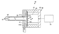
- FIG. 2 is a diagram showing a cut surface obtained by cutting the liquid ejecting apparatus 30 along the liquid ejecting direction. Note that the vertical and horizontal scales of the members and portions shown in FIG. 2 are different from actual ones for convenience of illustration.
- the pulse flow generator 40 changes the volume of the pressure chamber 44 into a cylindrical internal space formed by the first case 41, the second case 42, and the third case 43. Therefore, a piezoelectric element 45 and a diaphragm 46 are provided.
- the cases 41, 42, and 43 are joined and integrated on the surfaces facing each other.
- the diaphragm 46 is a disk-shaped thin metal plate, and an outer peripheral portion thereof is sandwiched and fixed between the first case 41 and the second case 42.
- the piezoelectric element 45 is, for example, a multilayer piezoelectric element, and one end is fixed to the diaphragm 46 between the diaphragm 46 and the third case 43 and the other end is fixed to the third case.
- the pressure chamber 44 is a space surrounded by the diaphragm 46 and a recess 411 formed on the surface of the first case 41 facing the diaphragm 46.
- an inlet channel 413 and an outlet channel 415 that communicate with the pressure chamber 44 are formed in the first case 41.
- the inner diameter of the outlet channel 415 is formed larger than the inner diameter of the inlet channel 413.
- the inlet channel 413 is connected to the connection tube 93 and introduces the liquid supplied from the liquid feeding pump 20 into the pressure chamber 44.
- One end of the injection pipe 50 is connected to the outlet channel 415, and a liquid flowing in the pressure chamber 44 is introduced into the injection pipe 50.
- a nozzle 60 having a liquid ejection opening 61 having an inner diameter that is smaller than the inner diameter of the ejection pipe 50 is inserted into the other end (tip) of the ejection pipe 50.
- the liquid stored in the container 10 is supplied to the connection tube 93 at a predetermined pressure or a predetermined flow rate by the liquid feed pump 20 under the control of the liquid ejection control device 70.
- the pulse flow generator 40 To be supplied to the pulse flow generator 40.
- the piezoelectric element 45 expands and contracts (arrow A in FIG. 2). Since the drive signal applied to the piezoelectric element 45 is repeatedly applied at a predetermined repetition frequency (for example, several tens to several hundreds of Hz), the expansion and contraction of the piezoelectric element 45 are repeated every period. As a result, a pulsation is imparted to the steady flow liquid flowing in the pressure chamber 44, and the pulsed liquid jet is repeatedly ejected from the liquid ejection opening 61.
- FIG. 3A is a diagram showing an example of a drive voltage waveform L11 of a drive signal for one cycle applied to the piezoelectric element 45, and also shows a liquid flow velocity waveform L13 in the liquid ejection opening 61.
- FIG. . Tp is a repetition period (a time corresponding to one period of the driving voltage waveform), and its reciprocal is the repetition frequency.
- FIG.3 (b) is the figure which extracted the main peak part which has the largest flow velocity among the peaks of the flow velocity waveform L13 shown to Fig.3 (a).
- the repetition period Tp is about 1 [ms (milliseconds)] to 100 [ms], and the time required for the drive voltage waveform to rise to the maximum voltage (rise time) Tpr is 10 [ ⁇ s (microseconds)] to It is about 1000 [ ⁇ s].
- the repetition period Tp is set as a time longer than the rise time Tpr. Further, when the reciprocal of the rise time is defined as the rise frequency, the repetition frequency is set as a frequency lower than the rise frequency.
- the piezoelectric element 45 expands when a positive voltage is applied, the piezoelectric element 45 rapidly expands at the rising time Tpr, and the diaphragm 46 is pushed by the piezoelectric element 45 and bends toward the pressure chamber 44 side.
- the diaphragm 46 is bent toward the pressure chamber 44, the volume of the pressure chamber 44 is reduced, and the liquid in the pressure chamber 44 is pushed out from the pressure chamber 44.
- the inner diameter of the outlet channel 415 is larger than the inner diameter of the inlet channel 413, the fluid inertance and fluid resistance of the outlet channel 415 are smaller than the fluid resistance of the inlet channel 413.
- the drive voltage will drop slowly.
- the piezoelectric element 45 contracts over a time longer than the rise time Tpr, and the diaphragm 46 is pulled by the piezoelectric element 45 and bent toward the third case 43 side.
- the diaphragm 46 is bent toward the third case 43, the volume of the pressure chamber 44 is increased, and the liquid is introduced into the pressure chamber 44 from the inlet channel 413.
- the liquid feed pump 20 supplies the liquid to the pulse flow generation unit 40 at a predetermined pressure or a predetermined flow rate, if the piezoelectric element 45 does not expand and contract, the liquid flowing in the pressure chamber 44 (steady flow) is It is introduced into the ejection pipe 50 through the outlet channel 415 and ejected from the liquid ejection opening 61. Since this injection is a constant-speed and low-speed liquid flow, it can be said that it is a steady flow.
- the value that characterizes the pulsed liquid jet is basically the flow velocity waveform L13 at the liquid ejection opening 61 of the jet for one pulse shown together with the drive voltage waveform L11 in FIG.
- the highest peak flow velocity waveform (first wave jet) that occurs immediately after the drive voltage rises.
- An enlarged view of this waveform is shown in FIG.
- the other low peak is caused by the jet jetting incidentally as the wave of pressure fluctuation generated in the pressure chamber 44 when the piezoelectric element 45 extends is reflected back and forth in the jet pipe 50.
- the drive voltage waveform of the piezoelectric element 45 is controlled.
- the driving voltage waveform can be controlled by a surgeon specifying the rising frequency of the driving voltage waveform and the amplitude (voltage amplitude) of the driving voltage waveform as the voltage characteristic value.
- the rising frequency here is one of index values related to the rising of the drive voltage, and is defined as the reciprocal of the rising time Tpr.
- the surgeon specifies the rising frequency with the voltage amplitude fixed, or specifies the voltage amplitude with the rising frequency fixed.
- the voltage amplitude and its rising frequency greatly affect the flow velocity waveform of the main jet.
- the drive voltage while slowly dropping after the drive voltage has risen to the maximum voltage does not significantly affect the flow velocity waveform of the main jet. For example, if the rising frequency is increased or the voltage amplitude is increased, the cutting depth is increased and the cutting volume is increased in proportion to the rising frequency.
- the cutting depth and the cutting volume of the cutting object that are actually achieved may not always change in accordance with the increase or decrease of the voltage characteristic value, and may deteriorate the usability. For example, even if the surgeon doubles the voltage amplitude, the cutting depth and volume will not increase as expected, or even if the voltage amplitude is halved, the cutting depth and volume will not decrease as expected. There was a case where it happened. Therefore, the situation where the cutting depth and the cutting volume which an operator desires cannot be achieved may arise. This is a problem that may lead to prolonged operation time.
- the piezoelectric element 45 can be controlled with a driving voltage waveform that is optimal for achieving the cutting depth and the cutting volume according to the operator's sense of operation. It is.
- the mass flux is a mass [kg / s] per unit time of the liquid passing through the liquid ejection opening 61.
- the momentum flux is the momentum [N] per unit time of the liquid passing through the liquid ejection opening 61.
- the energy flux is energy [W] per unit time of the liquid passing through the liquid ejection opening 61.
- Energy refers to kinetic energy and is hereinafter abbreviated as “energy”.
- FIG. 4 is a diagram showing mass flux Jm (a), momentum flux Jp (b), and energy flux Je (c) obtained from the flow velocity waveform of the main jet shown in FIG. 3 (b). If each of these mass flux Jm, momentum flux Jp, and energy flux Je is integrated within the time (duration) T from the rise to the fall of the flow velocity waveform of the main jet, the liquid jet opening as the main jet The mass, momentum, and energy of the liquid ejected from 61 can be obtained.
- mass flux Jm mass flux Jm
- momentum flux Jp energy flux Je
- mass, momentum, and energy calculated in the above manner can determine the cutting depth and cutting volume by the jet for one pulse. Conceivable. However, both are physical quantities including a steady flow component, and what is important is a value obtained by subtracting the contribution of the steady flow component.
- the maximum mass flux Jm_max [kg / s] obtained by subtracting the steady mass flux Jm_BG [kg / s] from the peak value (maximum value) of the mass flux Jm.
- the outflow mass M is expressed by the following formula (4).
- two parameters of momentum P [Ns] shown by hatching in FIG. 4B are defined by removing the steady flow component from the momentum of the liquid flowing out from the liquid ejection opening 61.
- the momentum P is expressed by the following equation (5).
- two parameters of energy E [J] shown in FIG. 4C are defined by removing the steady flow component from the energy of the liquid flowing out from the liquid ejection opening 61.
- the energy E is expressed by the following formula (6).
- the integration interval in the equations (4) to (6) is the time (duration) T from the rise to the fall of the main jet in each flow velocity waveform.
- the pulse liquid jet is a fluid
- the object to be cut is a flexible elastic body. Therefore, in order to simulate the fracture behavior of an object to be cut by a pulsed liquid jet, an appropriate fracture threshold is set on the flexible elastic body side, and a so-called fluid and structure (here, flexible elastic body) are coupled.
- Analysis fluid-structure interaction analysis (FSI)
- FEM finite element method
- SPH Smoothed Particle Particle
- a finite element method a particle method represented by SPH (Smoothed Particle Particle)
- the method etc. which combined these are mentioned.
- the method to be applied is not particularly limited and will not be described in detail, an optimal method was selected in consideration of the stability of the analysis result, the calculation time, etc., and the simulation was performed.
- the amplitude (maximum value of the flux) is set to 12 [m / s] or more for three types of sine wave, triangular wave, and rectangular wave.
- a total of 27 types were prepared by changing three types within a range of 76 [m / s] and a duration of 63 [ ⁇ s] to 200 [ ⁇ s].
- the flow rate of the steady flow is 1 [m / s].
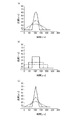
- FIG. 5 is a diagram showing a sine wave (a), a rectangular wave (b), and a triangular wave (c) given as flow velocity waveforms of the main jet in the simulation, each having a duration of 63 [ ⁇ s] indicated by a solid line.
- a pulsed liquid jet was generated by giving the prepared waveform as a flow velocity waveform of the main jet, and the fracture behavior of the flexible elastic body when it was shot into the flexible elastic body was simulated.
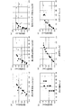
- the vertical axis represents the cutting depth of the object to be cut
- the horizontal axis represents the maximum mass flux Jm_max (a), the outflow mass M (b), the maximum momentum flux Jp_max (c), the momentum P (d), and the maximum.
- Jm_max a
- the outflow mass M b
- the maximum momentum flux Jp_max c
- the momentum P d
- the maximum It is the figure which plotted the result of the simulation made into energy flux Je_max (e) and energy E (f).
- a simulation result when a sine wave having a duration of 63 [ ⁇ s] is given as a flow velocity waveform of the main jet is plotted with “*”
- a simulation result when a sine wave of 125 [ ⁇ s] is given is shown as “
- the "-" plot shows the simulation results when a sine wave of 200 [ ⁇ s] is given.
- a simulation result when a triangular wave having a duration of 63 [ ⁇ s] is given as the flow velocity waveform of the main jet is a “+” plot
- a simulation result when a triangular wave of 125 [ ⁇ s] is given is a “ ⁇ ” plot.
- a simulation result when a triangular wave of 200 [ ⁇ s] is given is shown by a plot of “ ⁇ ”.
- the simulation result when a rectangular wave having a duration of 63 [ ⁇ s] is given as the flow velocity waveform of the main jet is plotted with “ ⁇ ”
- the simulation result when a rectangular wave of 125 [ ⁇ s] is given is black-filled.
- a triangular plot and a simulation result when a rectangular wave of 200 [ ⁇ s] is given are shown by a “ ⁇ ” plot.
- the outflow mass M and The relationship with the cutting depth largely varies depending on the waveform shape given as the flow velocity waveform of the main jet, and the correlation is low.
- the variation due to the shape of the given waveform is small, and the respective plots are distributed almost on the same curve.
- the momentum P has a smaller variation. Therefore, it can be said that the cutting depth is highly correlated with the momentum P and the energy E, and particularly well correlated with the momentum P.
- the simulation is performed for the case where the diameter of the liquid ejection opening is 0.15 [mm] and the standoff distance is 0.5 [mm].
- the standoff distance is 0.15 [mm]
- other liquid ejection opening diameters and other stands are used.
- a simulation was performed even at an off-distance, and it was confirmed that the qualitative tendency that the cutting depth was highly correlated with the momentum P and the energy E did not change significantly.
- the vertical axis represents the cutting volume of the object to be cut
- the horizontal axis represents the maximum mass flux Jm_max (a), the outflow mass M (b), the maximum momentum flux Jp_max (c), the momentum P (d), the maximum It is the figure which plotted the result of the simulation as energy flux Je_max (e) and energy E (f).
- the relationship between the waveform given as the flow velocity waveform of the main jet and the type of plot is the same as in FIG.
- the outflow mass M and The relationship with the cutting volume varies greatly depending on the waveform shape given as the flow velocity waveform of the main jet as well as the cutting depth, and the correlation is low.
- the variation due to the waveform shape given is the same as the cutting depth, and each plot is distributed almost on the same straight line.
- the energy E has a smaller variation than the momentum P. Therefore, it can be said that the cutting volume has a high correlation with the momentum P and the energy E, and particularly has a good correlation with the energy E.
- the simulation is performed for the case where the diameter of the liquid ejection opening is 0.15 [mm] and the standoff distance is 0.5 [mm]. However, other liquid ejection opening diameters and other stands are used. A simulation was also performed at an off-distance, and it was confirmed that the qualitative tendency that the cutting volume was highly correlated with the momentum P and the energy E did not change significantly.
- a typical drive voltage waveform that is actually applied to the piezoelectric element 45 is simulated in advance, and the correspondence between the momentum P and energy E, the rising frequency, and the voltage amplitude. Get a relationship.
- the corresponding rising frequency and voltage amplitude are specified according to the operation of increasing or decreasing the amount of exercise P or energy E by the operator, and the drive of the piezoelectric element 45 is controlled.
- the flow velocity waveform of the main jet was obtained by simulation by giving a driving voltage waveform in which the voltage amplitude was fixed and the rising frequency was changed stepwise.
- the flow velocity waveform of the main jet was obtained by simulation by giving a driving voltage waveform in which the rising frequency was fixed and the voltage amplitude was changed stepwise.
- the simulation can be performed, for example, using a numerical simulation based on an equivalent circuit method based on a model in which the flow path system of the liquid ejecting apparatus is replaced with fluid (flow path) resistance, fluid inertance, fluid compliance, and the like.
- fluid simulation using a finite element method (FEM), a finite volume method (FVM), or the like may be used.
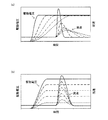
- FIG. 8A is a diagram showing a simulation result of the flow velocity waveform of the main jet when the rising frequency is changed.
- the flow velocity waveform of the main jet when the rising frequency is lowered (longer in terms of the rising time Tpr), the flow velocity waveform of the main jet has a longer duration without changing the rising timing, and its amplitude (flow velocity) The maximum value is also reduced.
- FIG. 8B is a diagram showing a simulation result of the flow velocity waveform of the main jet when the voltage amplitude is changed. As shown in FIG. 8B, when the voltage amplitude is reduced, the waveform amplitude (maximum value of the flow velocity) of the flow velocity waveform of the main jet is reduced while maintaining the duration, unlike the case where the rising frequency is reduced.
- FIG. 9 is a diagram showing a correspondence relationship between the obtained momentum P for each flow velocity waveform of the main jet, the rising frequency, and the voltage amplitude.
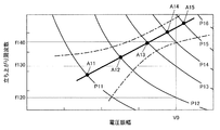
- This FIG. 9 is obtained by plotting the momentum P obtained in a coordinate space with the vertical axis as the rising frequency and the horizontal axis as the voltage amplitude, and drawing a contour line related to the momentum P.
- Each contour line is lower in the lower left of FIG. 9 and increases by a predetermined amount toward the upper right.
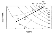
- FIG. 10 is a diagram showing the correspondence between the obtained energy E for each flow velocity waveform of the main jet, the rising frequency, and the voltage amplitude.
- energy E it is obtained by plotting the energy E obtained in a coordinate space with the vertical axis as the rising frequency and the horizontal axis as the voltage amplitude as shown in FIG.
- Each contour line is lower in the lower left of FIG. 10 and increases by a predetermined amount toward the upper right.
- the intervals between the contour lines are not equal, and the momentum P and the energy E do not change linearly in the coordinate axis direction.
- the voltage amplitude is fixed (for example, V0)
- the rising frequency is variable
- the drive voltage waveform of the piezoelectric element 45 is controlled.
- a frequency change between the rising frequencies f120 to f130 is required between the momentum indicating values P12 to P13
- a frequency between the rising frequencies f130 to f140 is required between the momentum indicating values P13 to P14.
- the operation performed by the surgeon during the operation is an increase / decrease operation of the momentum P using the lever switch 813 or an increase / decrease operation of the energy E.
- a reference line is defined in the coordinate space shown in FIG. 9, and the rising frequency and voltage amplitude at each intersection where the reference line intersects each contour line of the momentum P are acquired and tabulated. deep.
- the rising frequency and voltage amplitude at the intersections A11, A12,... With each contour line are associated with the momentum P of the corresponding contour line. Create a data table. Further, the momentum instruction values P11, P12,...
- contour lines are assigned in order to the lever positions of the lever switch 813 as the instruction values of the momentum P (momentum instruction values). According to this, the amount of change of the momentum P when the lever switch 813 is moved by one scale can be made substantially the same.
- a reference line is defined in the coordinate space shown in FIG. 10, and the rising frequency and voltage amplitude at each intersection where the reference line intersects each contour line of the energy E are acquired and tabulated. deep.
- the straight line indicated by a thick line in FIG. 10 is used as the reference line
- the rising frequency and voltage amplitude at the intersections A21, A22,... With each contour line are associated with the energy E of the corresponding contour line.
- the energy instruction values E21, E22,... Of the contour lines are sequentially assigned to the lever positions of the lever switch 813 as the energy E instruction values (energy instruction values). According to this, the amount of change in energy E when the lever switch 813 is moved by one scale can be made substantially the same.
- the reference line need not be a straight line.
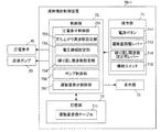
- FIG. 11 is a block diagram illustrating a functional configuration example of the liquid ejection control apparatus according to the first embodiment.
- the liquid ejection control device 70-1 includes an operation unit 71, a display unit 73, a control unit 75, and a storage unit 77.
- the operation unit 71 is realized by various switches such as a button switch, a lever switch, a dial switch, and a pedal switch, a touch panel, a track pad, a mouse, and other input devices, and sends an operation signal corresponding to the operation input to the control unit 75. Output to.
- the operation unit 71 includes a power button 711 realized by the button switch 811 of FIG. 1, a momentum adjusting lever 713 realized by the lever switch 813 of FIG. 1, and a repetition frequency setting realized by the lever switch 814 of FIG. Lever 714 and an injection switch 715 realized by the pedal switch 83 of FIG.
- the momentum adjustment lever 713 is for inputting the momentum instruction value.
- the surgeon operates the momentum adjusting lever 713, that is, the lever switch 813 shown in FIG. 1, selects the lever position marked with “1” to “5”, and increases / decreases the momentum P in five steps.
- Each lever position is assigned an exercise amount instruction value in advance so as to increase by a certain amount in proportion to the value of the corresponding scale.
- the number of lever position stages is not limited to five, and may be set as appropriate, such as three-stage adjustment of “large”, “medium”, and “small”.
- the repetition frequency setting lever 714 is for setting a repetition frequency.
- the surgeon operates the lever switch 814 in FIG. 1 and selects the lever position with the scales “1” to “5”, thereby repeating the repetition frequency ( (For example, several tens to several hundreds Hz) is increased or decreased in five steps.
- Each lever position is assigned a repetition frequency corresponding to the scale value. Note that the number of steps of the lever position is not limited to five, and the number of steps may be set as appropriate.
- the display unit 73 is realized by a display device such as an LCD (Liquid Crystal Display) or an EL display (Electroluminescence display), and displays various screens such as a setting screen based on a display signal input from the control unit 75. indicate.
- a display device such as an LCD (Liquid Crystal Display) or an EL display (Electroluminescence display)
- various screens such as a setting screen based on a display signal input from the control unit 75. indicate.
- the control unit 75 is realized by a microprocessor such as a CPU (Central Processing Unit) or a DSP (Digital Signal Processor), a control device such as an ASIC (Application Specific Integrated Circuit), and an arithmetic unit. Control all parts centrally.
- the control unit 75 includes a piezoelectric element control unit 751, a pump control unit 756, and a momentum display control unit 757.
- each part which comprises the control part 75 is good also as comprising with hardware, such as a dedicated module circuit.
- the piezoelectric element control unit 751 includes a rising frequency setting unit 752 that sets a rising frequency according to the lever position of the momentum adjusting lever 713, a voltage amplitude setting unit 753 that sets a voltage amplitude according to the lever position of the momentum adjusting lever 713, and a repetition frequency setting. And a repetition frequency setting unit 754 that sets a repetition frequency according to the lever position of the lever 714.
- the piezoelectric element control unit 751 generates a drive voltage waveform and applies a drive signal having the generated waveform to the piezoelectric element 45. At this time, the rising frequency set by the rising frequency setting unit 752 and the voltage amplitude setting unit 753 are applied. Generates a drive voltage waveform according to the set voltage amplitude.
- the pump control unit 756 outputs a drive signal to the liquid feed pump 20 to drive the liquid feed pump 20.
- the exercise amount display control unit 757 performs control to display the exercise amount instruction value (that is, the current value of the exercise amount P) assigned to the selected lever position of the exercise amount adjustment lever 713 on the display unit 73.
- the storage unit 77 is realized by various IC (Integrated Circuit) memory such as ROM (Read Only Memory), flash ROM, RAM (Random Access Memory), or a storage medium such as a hard disk.
- IC Integrated Circuit
- ROM Read Only Memory
- RAM Random Access Memory
- a program for operating the liquid ejection system 1 and realizing various functions provided in the liquid ejection system 1, data used during the execution of the program, and the like are stored in advance, or Stored temporarily for each process.
- This momentum conversion table 771 is stored in the storage unit 77.
- This momentum conversion table 771 is a data table in which the correspondence between the momentum P described above with reference to FIG. 9, the rising frequency, and the voltage amplitude is set, and an example is shown in FIG.
- FIG. 12 is a diagram showing a data configuration example of the momentum conversion table 771.
- the momentum instruction value, the rising frequency, and the voltage amplitude assigned to the corresponding lever position are set in association with the lever position (scale).
- the rising frequency setting unit 752 reads the rising frequency at the selected lever position from the momentum conversion table 771 and sets it.
- the voltage amplitude setting unit 753 reads out and sets the voltage amplitude at the selected lever position from the momentum conversion table 771.
- the piezoelectric element 45 has a drive voltage waveform such that the momentum P becomes the momentum instruction value P13 assigned to the lever position “3”. Is controlled.
- the data configuration example of the momentum conversion table 771 in FIG. 12 is an example, and as described above, a desired straight line or curve may be used as a reference line in addition to the straight line or curve shown by the thick line or the alternate long and short dash line in FIG. it can. That is, the rising frequency and voltage amplitude at the intersections of the desired reference line and the contour lines of the momentum instruction values P11, P12,... May be set in the momentum conversion table 771.
- the momentum conversion table 771 that obtains the momentum instruction values P11, P12,... By changing the rising frequency with the voltage amplitude constant may be set. For example, as shown in FIG. 13, the voltage amplitude is constant at V1, and the rising frequencies f111, f121,... At which the rising frequencies become the momentum instruction values P11, P12,. Can do. By changing / setting the rising frequency in accordance with the exercise amount conversion table 771, the exercise amount P can be changed / set to the instructed value.
- the momentum conversion table 771 for obtaining the momentum instruction values P11, P12,... May be set by changing the voltage amplitude while keeping the rising frequency constant. For example, as shown in FIG. 13, the rising frequency is constant at f1, and the voltage amplitudes V111, V121,... At which the voltage amplitude becomes the momentum instruction values P11, P12,. Can do.
- the momentum P can be changed / set to the instructed value.
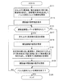
- FIG. 14 is a flowchart showing a flow of processing performed by the control unit 75 when jetting a pulsed liquid jet.
- the pump control unit 756 sends the liquid.
- the pump 20 is driven, and the piezoelectric element control unit 751 drives the piezoelectric element 45 to start jetting a pulsed liquid jet (step S111).
- the rising frequency setting unit 752 acquires the lever position of the currently selected momentum adjusting lever 713, reads the rising frequency from the momentum conversion table 771, and sets the rising frequency.
- the voltage amplitude setting unit 753 reads the acquired voltage amplitude at the lever position from the momentum conversion table 771 and sets the voltage amplitude. Further, the repetition frequency setting unit 754 acquires the lever position of the currently selected repetition frequency setting lever 714 and sets the repetition frequency. Then, the piezoelectric element control unit 751 generates a drive voltage waveform according to the rising frequency, the voltage amplitude, and the repetition frequency, and applies the generated drive voltage waveform drive signal to the piezoelectric element 45.
- the exercise amount display control unit 757 reads out the exercise amount instruction value assigned to the acquired lever position from the exercise amount conversion table 771 and performs control to display it on the display unit 73 (step S113).
- the control unit 75 monitors the operation of the momentum adjusting lever 713 in step S115 until it is determined that the injection of the pulsed liquid jet is terminated by the operation of the injection switch 715 (step S125: NO).
- the momentum adjustment lever 713 is operated (step S115: YES)
- the rising frequency setting unit 752 reads the rising frequency at the selected lever position from the momentum conversion table 771, and updates the setting of the rising frequency.
- the voltage amplitude setting unit 753 reads the voltage amplitude at the selected lever position from the momentum conversion table 771, and updates the voltage amplitude setting (step S119).
- the piezoelectric element control unit 751 generates a drive voltage waveform according to the set repetition frequency, rising frequency, and voltage amplitude, and applies a drive signal of the generated drive voltage waveform to the piezoelectric element 45 (step S121).
- the exercise amount display control unit 757 reads out the exercise amount instruction value assigned to the selected lever position from the exercise amount conversion table 771, and performs control to update the display of the display unit 73 (step S123).
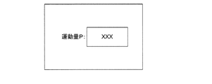
- FIG. 15 is a diagram showing an example of a display screen displayed in step S113 and updated and displayed in step S123. With this display screen, the operator can work while grasping the current value of the momentum P related to the pulsed liquid jet ejected from the liquid ejection opening 61 during the operation.
- the display of the momentum instruction value is not limited to the display of the numerical values shown in FIG. 15 but may be performed by meter display, or the change in the amount of exercise P accompanying the increase / decrease operation from the start of injection of the pulsed liquid jet May be displayed in a graph.
- the exercise amount display control unit 757 may display not only the instruction value of the exercise amount P on the display unit 73 but also the instruction value of the exercise amount P and the repetition frequency. Further, in addition to the instruction value and the repetition frequency of the momentum P, at least one of the current rising frequency (or rising time) and voltage amplitude may be displayed together.
- the drive voltage waveform of the piezoelectric element 45 can be controlled. For example, if the momentum adjustment lever 713 is moved by one scale, the momentum P corresponding to the scale interval changes, so that the cutting depth and the cutting volume can be set according to the user's senses and intentions. Can be improved.
- FIG. 16 is a block diagram illustrating a functional configuration example of the liquid ejection control apparatus according to the second embodiment.
- the liquid ejection control apparatus 70-2 includes an operation unit 71a, a display unit 73, a control unit 75a, and a storage unit 77a.
- the operation unit 71a includes an energy adjustment lever 716a realized by the lever switch 813 of FIG.
- the energy adjustment lever 716a is for inputting an energy instruction value.
- the surgeon operates the energy adjustment lever 716a, that is, the lever switch 813 in FIG. 1, selects the lever position marked with “1” to “5”, and increases or decreases the energy E in five stages.
- An energy instruction value is assigned to each lever position in advance so as to increase by a certain amount in proportion to the value of the corresponding scale.
- the number of lever position stages is not limited to five, and may be set as appropriate, such as three-stage adjustment of “large”, “medium”, and “small”.
- the control unit 75a includes a piezoelectric element control unit 751a, a pump control unit 756, and an energy display control unit 758a.
- the piezoelectric element control unit 751a includes a frequency setting unit 752a that sets a rising frequency according to the lever position of the energy adjustment lever 716a, a voltage amplitude setting unit 753a that sets a voltage amplitude according to the lever position of the energy adjustment lever 716a, and a repetition frequency setting.
- a repetition frequency setting unit 754a that sets a repetition frequency according to the lever position of the lever 714.
- the piezoelectric element control unit 751a generates a drive voltage waveform and applies a drive signal having the generated waveform to the piezoelectric element 45. At this time, the rising frequency set by the frequency setting unit 752a and the voltage amplitude setting unit 753a A drive voltage waveform is generated according to the set voltage amplitude.
- the energy display control unit 758a performs control to display the energy instruction value assigned to the lever position of the currently selected energy adjustment lever 716a on the display unit 73.
- the energy display control unit 758a shown in FIG. 19 may display not only the instruction value of the energy E on the display unit 73 but also the repetition frequency. Furthermore, at least one of the current rising frequency (or rising time) and voltage amplitude may be displayed together.
- the energy conversion table 772a is stored in the storage unit 77a.
- This energy conversion table 772a is a data table in which the correspondence relationship between the energy E, the rising frequency, and the voltage amplitude described above with reference to FIG. 10 is set, and FIG. 17 shows an example.
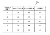
- FIG. 17 is a diagram illustrating a data configuration example of the energy conversion table 772a.
- an energy instruction value assigned to the corresponding lever position, a rising frequency, and a voltage amplitude are set in association with the lever position (scale).
- the frequency setting unit 752a reads and sets the rising frequency of the selected lever position from the energy conversion table 772a.
- the voltage amplitude setting unit 753a reads the voltage amplitude at the selected lever position from the energy conversion table 772a and sets it.
- the piezoelectric element 45 has a drive voltage waveform such that the energy E becomes the energy instruction value E23 assigned to the lever position “3”. Is controlled.
- the data configuration example of the energy conversion table 772a in FIG. 17 is an example, and as described above, a desired straight line or curve is used as a reference line in addition to the straight line or curve shown by the thick line or the alternate long and short dash line in FIG. You can also. That is, the rising frequency and the voltage amplitude at the intersection of the desired reference line and the contour lines of the energy instruction values E21, E22,... May be set in the energy conversion table 772a.
- the energy conversion table 772a which obtains energy instruction
- the voltage amplitude is constant at V2
- the rising frequency is constant at f2
- the second embodiment based on the correspondence relationship between the preset energy E, the rising frequency and the voltage amplitude, according to the optimal rising frequency and voltage amplitude to achieve the cutting depth and cutting volume according to the operation feeling.
- the drive voltage waveform of the piezoelectric element 45 can be controlled. For example, if the energy adjustment lever 716a is moved by one scale, the energy E corresponding to the scale interval changes. Therefore, the cutting depth and the cutting volume can be set according to the user's senses and intentions. Can be improved.
- the lever switch 813 when the momentum P is increased or decreased stepwise by the lever switch 813 (momentum adjustment lever 713), or when the energy E is increased or decreased stepwise by the lever switch 813 (energy adjustment lever 716a).
- the lever switch 813 may be configured such that the momentum instruction value and the energy instruction value can be adjusted steplessly even between the marked lever positions.
- the scale before and after the selected momentum P is referred to with reference to the momentum conversion table 771 shown in FIG.
- the momentum instruction value, the rising frequency, and the voltage amplitude associated with the lever position are read out. Then, the read rising frequency and voltage amplitude are linearly interpolated to specify the rising frequency and voltage amplitude corresponding to the currently selected momentum P.
- the rise frequency and voltage amplitude corresponding to the lever positions (momentum instruction values) on the front and rear scales are read out, and the read rise frequency and voltage amplitude are respectively expressed as polynomials.
- the rising frequency and the voltage amplitude corresponding to the currently selected momentum P may be specified by interpolation or the like.
- the reference line indicated by the thick line or the alternate long and short dash line in FIG. 9 is actually expressed as a curve in the space with the voltage amplitude, the rising frequency, and the momentum as coordinate axes.
- An equation corresponding to this curve may be obtained in advance, and the rising frequency and voltage amplitude corresponding to the momentum P of the selected lever position may be specified from this equation.
- the lever position (energy) of the scale before and after the selected energy E is referred to by referring to the energy conversion table 772a shown in FIG.
- the rising frequency and voltage amplitude corresponding to the indicated value) are read out.
- the read rising frequency and voltage amplitude are respectively linearly interpolated to specify the rising frequency and voltage amplitude corresponding to the currently selected energy E.
- the rising frequency and voltage amplitude corresponding to the lever positions (energy indication values) on the front and rear scales are read, and the read rising frequency and voltage amplitude are respectively expressed as polynomials.
- the rise frequency and voltage amplitude corresponding to the currently selected energy E may be specified by interpolation or the like.
- the reference line indicated by the thick line or the alternate long and short dash line in FIG. 10 is actually expressed as a curve in the space with the voltage amplitude, the rising frequency, and the energy as coordinate axes.
- An equation corresponding to this curve may be obtained in advance, and the rising frequency and voltage amplitude corresponding to the energy E of the selected lever position may be specified from this equation.
- a momentum conversion table 771 and an energy conversion table 772a are prepared for each type of the liquid ejecting apparatus 30, and are stored in the storage units 77 and 77a, and the momentum conversion table 771 and the energy conversion corresponding to the type of the liquid ejecting apparatus 30 are stored.
- the table 772a or the like may be selectively used.
- a pulsed liquid jet such as a difference in inner diameter and length of the liquid injection opening 61 and the nozzle 60, a difference in inner diameter and length of the injection tube 50, a difference in characteristics of the piezoelectric element 45, a difference in volume of the pressure chamber 44, etc. It is preferable to prepare for each type of liquid ejecting apparatus 30 having a different structure related to the ejection of the liquid.
- Cutting materials such as gel materials, rubbers, plastics, etc. depending on the part of the affected area if used for surgical purposes, or depending on the type of food if used for food processing If the application is used, the liquid ejecting apparatus 30 may be exchanged for a different type depending on the type of each material, that is, the shape, density, fracture threshold, elastic modulus, viscosity, etc. of the target material to be cut. is there.
- liquid ejecting control apparatus 70 reads out the information from the connected liquid ejecting apparatus 30, and the momentum conversion table 771 and the energy conversion table 772a. It is more preferable to switch automatically.
- the rising frequency is exemplified as the index value related to the rising.
- the rising time Tpr may be used instead of the rising frequency.
- the momentum adjustment lever 713 and the energy adjustment lever 716a are not limited to being realized by the lever switch 813, and may be realized by a dial switch, a button switch, or the like, for example.
- the display unit 73 may be realized as a touch panel by a software key switch or the like. In this case, the user performs a touch operation on the touch panel, which is the display unit 73, and inputs an instruction value for the amount of exercise or energy.
- the piezoelectric element control units 751 and 751a have been described as generating the drive voltage waveform according to the set repetition frequency, rising frequency, and voltage amplitude (for example, step S121 in FIG. 14).
- a drive voltage waveform for one cycle is generated in advance and stored in the storage units 77 and 77a as waveform data associated with the combination. Keep it. Then, the waveform data corresponding to the set combination of the repetition frequency, the rising frequency, and the voltage amplitude may be read, and a drive signal according to the read waveform data may be applied to the piezoelectric element 45.
- a configuration in which a pulsed liquid jet having a momentum of 2 nNs to 2 mNs or a kinetic energy of 2 nJ to 200 mJ is disclosed, but more preferably, a momentum of 20 nNs to 200 ⁇ Ns Is preferable to eject a pulsed liquid jet of 40 nJ or more and 10 mJ or less.
- a biological tissue and gel material can be cut suitably.
Landscapes
- Engineering & Computer Science (AREA)
- Health & Medical Sciences (AREA)
- Life Sciences & Earth Sciences (AREA)
- Mechanical Engineering (AREA)
- Surgery (AREA)
- General Engineering & Computer Science (AREA)
- Molecular Biology (AREA)
- Medical Informatics (AREA)
- Heart & Thoracic Surgery (AREA)
- Animal Behavior & Ethology (AREA)
- General Health & Medical Sciences (AREA)
- Public Health (AREA)
- Veterinary Medicine (AREA)
- Forests & Forestry (AREA)
- Biomedical Technology (AREA)
- Nuclear Medicine, Radiotherapy & Molecular Imaging (AREA)
- Surgical Instruments (AREA)
- Reciprocating Pumps (AREA)
Abstract
液体噴射制御装置(70-1)において、操作部(71)は、液体噴射装置から噴射されるパルス液体ジェットに係る運動量又は運動エネルギーの指示値を入力するための調整レバー(713)を含む。また、制御部(75)は、運動量又は運動エネルギーがそれぞれの指示値となるように、圧電素子(45)に印加する駆動電圧波形の立ち上がり周波数を設定する周波数設定部(752)と、駆動電圧波形の振幅を設定する振幅設定部(753)とを備える。
Description
本発明は、圧電素子を用いて液体をパルス状に噴射する液体噴射装置を制御する液体噴射制御装置等に関する。
液体をパルス状に噴射して切削対象物を切削する技術が知られている。パルス状の液体の噴射は、ノズルから脈動的に噴射される液体のジェット流であり、本明細書では適宜「パルス液体ジェット(Pulsed Liquid Jet)」と称する。
パルス液体ジェットの用途は様々であるが、例えば、特許文献1には、医療分野における外科手術用として利用する技術が提案されている。この場合には、切削対象物は、生体組織となり、液体は生理食塩水となる。
パルス液体ジェットを生成する機構の1つに、圧電素子を用いた機構が知られている。パルス波状の駆動電圧を圧電素子に加えることで、圧電素子が作動流体(液体)内に瞬間的な圧力を発生させて液体をパルス状に噴射する機構である。そのため、パルス液体ジェットの強さを変更する場合には、圧電素子に印加する駆動電圧を制御することとなる。
そこで、圧電素子に印加する駆動電圧の特性値、例えば、駆動電圧波形の振幅(電圧振幅のことであり、駆動電圧の大きさとも言える)を、操作ダイヤルや操作ボタン等の操作部で指定することで、パルス液体ジェットの強さを可変する仕様が考えられる。
しかしながら、操作部で指定する駆動電圧の特性値を変化させても、切削対象物の切削深さや切削体積を、ユーザーが思うように変化させることができない場合があることが分かった。詳細は後述するが、例えば、ユーザーが電圧振幅を2倍や4倍、或いは1/2、1/4に変えたとしても、必ずしも切削深さや切削体積がその通りに変化するとは限らないことが分かった。パルス液体ジェットを外科手術用途で用いる場合には、術者の操作感覚通りの作用が得られず、問題となり得た。
本発明は上述した課題に鑑みて考案されたものであり、その目的とするところは、パルス液体ジェットの強さを、ユーザーの意図に沿った設定とすることを可能とし、使い勝手を向上させる技術を提案することである。
以上の課題を解決するための第1の発明は、圧電素子を用いて液体をパルス状に噴射する液体噴射装置に電気的に接続され該液体噴射装置を制御することが可能な液体噴射制御装置であって、前記液体噴射装置から噴射されるパルス液体ジェットに係る運動量又は運動エネルギーの指示値を入力するための操作部と、前記指示値となるように、前記圧電素子に印加する駆動電圧波形の振幅及び当該駆動電圧波形の立ち上がりに係る指標値を制御する制御部と、を備えた液体噴射制御装置である。
この場合、他の発明として、圧電素子を用いて液体をパルス状に噴射する液体噴射装置の制御方法であって、前記液体噴射装置から噴射されるパルス液体ジェットに係る運動量又は運動エネルギーの指示値を入力することと、前記指示値となるように、前記圧電素子に印加する駆動電圧波形の振幅及び当該駆動電圧波形の立ち上がりに係る指標値を制御することと、を含む制御方法を構成することとしてもよい。
また、第2の発明は、圧電素子を用いて液体をパルス状に噴射する液体噴射装置に電気的に接続され該液体噴射装置を制御することが可能な液体噴射制御装置であって、前記液体噴射装置から噴射されるパルス液体ジェットに係る運動量又は運動エネルギーの指示値を入力するための操作部と、前記指示値となるように、前記圧電素子に印加する駆動電圧波形の振幅又は当該駆動電圧波形の立ち上がりに係る指標値を制御する制御部と、を備えた液体噴射制御装置である。
この場合、他の発明として、圧電素子を用いて液体をパルス状に噴射する液体噴射装置の制御方法であって、前記液体噴射装置から噴射されるパルス液体ジェットに係る運動量又は運動エネルギーの指示値を入力することと、前記指示値となるように、前記圧電素子に印加する駆動電圧波形の振幅又は当該駆動電圧波形の立ち上がりに係る指標値を制御することと、を含む制御方法を構成することとしてもよい。
この第1の発明および第2の発明等によれば、液体噴射装置から噴射されるパルス液体ジェットに係る運動量又は運動エネルギーの指示値を入力すると、当該指示値となるように圧電素子に印加する駆動電圧波形の振幅及び立ち上がりに係る指標値のうちの少なくとも一方が制御される。後述するように、切削深さや切削体積は、パルス液体ジェットに係る運動量又は運動エネルギーと相関が高い。そのため、パルス液体ジェットに係る運動量又は運動エネルギーを直接指示することで、ユーザーの意図や操作感覚に見合った切削深さや切削体積を実現することができ、使い勝手を向上させることができる。
また、第3の発明は、第1又は第2の発明において、前記パルス液体ジェットに係る運動量又は運動エネルギーの前記指示値を表示させる制御を行う表示制御部、を更に備えた液体噴射制御装置である。
この第3の発明によれば、パルス液体ジェットに係る運動量又は運動エネルギーの指示値を表示させることができる。このため、ユーザーは、希望するパルス液体ジェットの強さや、現在の強さを表す指標を視覚的に確認することができる。よって、使い勝手を更に向上させることができる。
また、第4の発明は、第1~第3の何れかの発明において、前記パルス液体ジェットの運動量が2nNs(ナノニュートン秒)以上2mNs(ミリニュートン秒)以下、又は運動エネルギーが2nJ(ナノジュール)以上200mJ(ミリジュール)以下の前記液体噴射装置を制御する、液体噴射制御装置である。
この第4の発明によれば、パルス液体ジェットの運動量が2nNs以上2mNs以下、又は運動エネルギーが2nJ以上200mJ以下であり、その範囲で液体噴射装置を制御することができる。よって、例えば、生体組織や食品、ゲル材料、ゴムやプラスチックなどの樹脂材料などの柔軟素材を切削するのに好適である。
また、第5の発明は、第1~4の何れかの発明において、前記パルス液体ジェットによって生体組織を切削するための前記液体噴射装置を制御する、液体噴射制御装置である。
この第5の発明によれば、例えば、外科手術用途に好適なパルス液体ジェットの強さを制御することができる。
また、第6の発明は、第1~第5の何れかの発明において、前記立ち上がりに係る指標値は、前記駆動電圧波形の立ち上がりに係る時間、又は周波数によって表される、液体噴射制御装置である。
この第6の発明によれば、立ち上がりに係る指標値を、駆動電圧波形の立ち上がりに係る時間、又は周波数によって表すことができる。
また、第7の発明は、第1~第6の何れかの発明の液体噴射制御装置と、液体噴射装置と、送液ポンプ装置とを具備した液体噴射システムである。
この第7の発明によれば、第1~第6の発明の作用効果を奏する液体噴射システムを実現することができる。
以下、本発明の液体噴射制御装置及び制御方法を実施するための一形態について説明する。なお、以下説明する実施形態によって本発明が限定されるものではなく、本発明を適用可能な形態が以下の実施形態に限定されるものでもない。また、図面の記載において、同一部分には同一の符号を付す。
[全体構成]
図1は、本実施形態における液体噴射システム1の全体構成例を示す図である。この液体噴射システム1は、柔軟素材、例えば生体組織を切削対象物とした外科手術用、食品を切削対象物とした食品加工用、ゲル材料の加工用、又はゴムやプラスチックなど樹脂材料の切削加工の用途で用いられるものであり、運動量が2nNs(ナノニュートン秒)以上2mNs(ミリニュートン秒)以下、又は、運動エネルギーが2nJ(ナノジュール)以上200mJ(ミリジュール)以下のパルス液体ジェットを噴射して切削対象物を切削する。以下では、液体噴射システム1を外科手術用の用途で用い、患部(生体組織)の切開、切除、又は破砕(以下包括して「切削」という)を行う場合を例示する。また、本実施形態における運動量流速および運動量とは、パルス液体ジェットの噴射方向成分のみを考えたスカラー量、すなわち大きさを指すこととして説明する。
図1は、本実施形態における液体噴射システム1の全体構成例を示す図である。この液体噴射システム1は、柔軟素材、例えば生体組織を切削対象物とした外科手術用、食品を切削対象物とした食品加工用、ゲル材料の加工用、又はゴムやプラスチックなど樹脂材料の切削加工の用途で用いられるものであり、運動量が2nNs(ナノニュートン秒)以上2mNs(ミリニュートン秒)以下、又は、運動エネルギーが2nJ(ナノジュール)以上200mJ(ミリジュール)以下のパルス液体ジェットを噴射して切削対象物を切削する。以下では、液体噴射システム1を外科手術用の用途で用い、患部(生体組織)の切開、切除、又は破砕(以下包括して「切削」という)を行う場合を例示する。また、本実施形態における運動量流速および運動量とは、パルス液体ジェットの噴射方向成分のみを考えたスカラー量、すなわち大きさを指すこととして説明する。
図1に示すように、液体噴射システム1は、液体を収容する容器10と、送液ポンプ20と、切削対象物(本実施形態では生体組織)に向けて液体をパルス状に噴射するための液体噴射装置30と、液体噴射制御装置70とを備える。
この液体噴射システム1において、液体噴射制御装置70は、術者が手術の際に操作する操作パネル80を備える。操作パネル80には、電源のON/OFFを切り替えるためのボタンスイッチ811と、運動量又は運動エネルギーの増減操作のために「1」~「5」の目盛りが付された5段階のレバー位置を選択可能なレバースイッチ813と、繰り返し周波数を入力するために「1」~「5」の目盛りが付された5段階のレバー位置を選択可能な繰り返し周波数設定用のレバースイッチ814と、液晶モニター82とが配設されている。また、液体噴射制御装置70は、術者が足で踏んでパルス液体ジェットの噴射開始及び噴射停止を切り替えるためのペダルスイッチ83を備える。
容器10は、水や生理食塩水、薬液等の液体を収容する。送液ポンプ20は、容器10に収容された液体を、接続チューブ91,93を介して常時所定の圧力又は所定の流量で液体噴射装置30のパルス流発生部40に供給する。
液体噴射装置30は、手術に際して術者が手に持って操作する部分(ハンドピース)であり、送液ポンプ20から供給される液体に脈動を付与してパルス流を発生させるパルス流発生部40と、パイプ状の噴射管50とを備え、パルス流発生部40によって発生させたパルス流を、噴射管50を通り最終的にノズル60に設けられた液体噴射開口部61からパルス液体ジェットとして噴射する装置である。
ここでパルス流とは、液体の流速や圧力が時間的に大きく且つ急激に変化する液体の脈動的な流れを意味する。同様に、液体をパルス状に噴射するとは、ノズルを通過する液体の流速が、時間的に大きく変化する、液体の脈動的な噴射を意味する。本実施形態では、定常流に周期的な脈動を付与することで生じるパルス液体ジェットを噴射する場合を例示するが、液体の噴射と非噴射とを繰り返す間欠的、断続的なパルス液体ジェットの噴射にも本発明は同様に適用できる。
図2は、液体噴射装置30を液体の噴射方向に沿って切断した切断面を示す図である。なお、図2に示す部材や部分の縦横の縮尺は、図示の便宜上実際のものとは異なる。図2に示すように、パルス流発生部40は、第1ケース41と、第2ケース42と、第3ケース43とによって形成された円筒状の内部空間に、圧力室44の容積を変化させるための圧電素子45及びダイアフラム46が配設されて構成される。各ケース41,42,43は、互いに対向する面において接合され一体化されている。
ダイアフラム46は、円盤状の金属薄板であり、その外周部分が第1ケース41と第2ケース42との間に挟まれて固定されている。圧電素子45は、例えば積層型圧電素子であり、ダイアフラム46と第3ケース43との間で一端がダイアフラム46に固定され、他端が第3ケースに固定されている。
圧力室44は、ダイアフラム46と、第1ケース41のダイアフラム46に対向する面に形成された凹部411とによって囲まれた空間である。第1ケース41には、圧力室44に各々連通する入口流路413と出口流路415とが形成されている。出口流路415の内径は、入口流路413の内径よりも大きく形成されている。入口流路413は接続チューブ93と接続され、送液ポンプ20から供給される液体を圧力室44に導入する。出口流路415には噴射管50の一端が接続され、圧力室44内を流動する液体を噴射管50に導入する。噴射管50の他端(先端)には、噴射管50の内径よりも縮小された内径の液体噴射開口部61を有するノズル60が挿着されている。
以上のように構成される液体噴射システム1において、容器10に収容された液体は、液体噴射制御装置70の制御のもと送液ポンプ20によって、所定の圧力又は所定の流量で接続チューブ93を介してパルス流発生部40に供給される。一方で、液体噴射制御装置70の制御のもと圧電素子45に駆動信号が印加されると、圧電素子45が伸長・収縮する(図2の矢印A)。圧電素子45に印加される駆動信号は所定の繰り返し周波数(例えば数十~数百Hz)で繰り返し印加されるため、周期毎に圧電素子45の伸長と収縮が繰り返されることとなる。これにより圧力室44内を流動する定常流の液体に脈動が付与され、液体噴射開口部61からパルス液体ジェットが繰り返し噴射される。
図3(a)は、圧電素子45に印加される1周期分の駆動信号の駆動電圧波形L11の一例を示す図であり、液体噴射開口部61における液体の流速波形L13を併せて示している。Tpは繰り返し周期(駆動電圧波形の1周期分の時間)であり、その逆数が前記の繰り返し周波数である。
また、図3(b)は、図3(a)に示す流速波形L13のピークのうち、最大流速を有する主ピーク部分を抜き出した図である。なお、繰り返し周期Tpは1[ms(ミリ秒)]~100[ms]程度とされ、駆動電圧波形が最大電圧まで立ち上がるのに要する時間(立ち上がり時間)Tprは10[μs(マイクロ秒)]~1000[μs]程度とされる。
繰り返し周期Tpは、立ち上がり時間Tprよりも長い時間として設定される。また、立ち上がり時間の逆数を立ち上がり周波数としたとき、前記の繰り返し周波数は、立ち上がり周波数よりも低い周波数として設定される。
また、図3(b)は、図3(a)に示す流速波形L13のピークのうち、最大流速を有する主ピーク部分を抜き出した図である。なお、繰り返し周期Tpは1[ms(ミリ秒)]~100[ms]程度とされ、駆動電圧波形が最大電圧まで立ち上がるのに要する時間(立ち上がり時間)Tprは10[μs(マイクロ秒)]~1000[μs]程度とされる。
繰り返し周期Tpは、立ち上がり時間Tprよりも長い時間として設定される。また、立ち上がり時間の逆数を立ち上がり周波数としたとき、前記の繰り返し周波数は、立ち上がり周波数よりも低い周波数として設定される。
例えば、圧電素子45は、正の電圧が印加されると伸長するものとすると、立ち上がり時間Tprで急激に伸長し、ダイアフラム46が圧電素子45に押されて圧力室44側に撓む。ダイアフラム46が圧力室44側へと撓むと圧力室44の容積が小さくなり、圧力室44内の液体は圧力室44から押し出される。ここで、出口流路415の内径は入口流路413の内径よりも大きいため、出口流路415の流体イナータンスおよび流体抵抗は、入口流路413の流体抵抗よりも小さい。したがって、圧電素子45が急激に伸長することで圧力室44から押し出される液体の大部分は出口流路415を通って噴射管50に導入され、その内径よりも小径の液体噴射開口部61によりパルス状の液滴、すなわちパルス液体ジェットとなって高速噴射される。
最大電圧まで上昇した後は、駆動電圧は緩やかに降下する。その際、圧電素子45は、立ち上がり時間Tprよりも長い時間をかけて収縮し、ダイアフラム46が圧電素子45に引かれて第3ケース43側に撓む。ダイアフラム46が第3ケース43側に撓むと圧力室44の容積が大きくなり、入口流路413から圧力室44内に液体が導入される。
なお、送液ポンプ20は所定圧力又は所定流量で液体をパルス流発生部40に供給しているため、圧電素子45が伸縮動作を行わなければ、圧力室44を流動する液体(定常流)は出口流路415を経て噴射管50に導入され、液体噴射開口部61から噴射される。この噴射は定速かつ低速の液流であるため、定常流と言える。
[原理]
パルス液体ジェットを特徴付ける値として基本となるのは、図3(a)において駆動電圧波形L11と併せて示したパルス1個分のジェットの液体噴射開口部61における流速波形L13である。そのうち、注目すべきなのは、駆動電圧の立ち上がり直後に発生する最も高いピークの流速波形(先頭波のジェット)である。この波形の拡大図を図3(b)に示す。その他の低いピークは、圧電素子45の伸長時に圧力室44内に生じた圧力変動の波が噴射管50内を反射往復することで付随的に噴射されるジェットに起因するものであるが、切削対象物の破壊状態すなわち切削対象物の切削深さや切削体積を決定付けるのは、流速が最も大きい先頭波のジェット(主ジェット)である。
パルス液体ジェットを特徴付ける値として基本となるのは、図3(a)において駆動電圧波形L11と併せて示したパルス1個分のジェットの液体噴射開口部61における流速波形L13である。そのうち、注目すべきなのは、駆動電圧の立ち上がり直後に発生する最も高いピークの流速波形(先頭波のジェット)である。この波形の拡大図を図3(b)に示す。その他の低いピークは、圧電素子45の伸長時に圧力室44内に生じた圧力変動の波が噴射管50内を反射往復することで付随的に噴射されるジェットに起因するものであるが、切削対象物の破壊状態すなわち切削対象物の切削深さや切削体積を決定付けるのは、流速が最も大きい先頭波のジェット(主ジェット)である。
ところで、パルス液体ジェットの強さを変えて切削対象物の切削深さや切削体積を変化させたい場合には、圧電素子45の駆動電圧波形を制御することになる。この駆動電圧波形の制御は、その電圧特性値である駆動電圧波形の立ち上がり周波数や駆動電圧波形の振幅(電圧振幅)を術者が指定することによって行う方法が考えられる。ここでいう立ち上がり周波数は、駆動電圧の立ち上がりに係る指標値の1つであり、立ち上がり時間Tprの逆数と定義する。例えば、電圧振幅を固定にした状態で術者が立ち上がり周波数を指定したり、立ち上がり周波数を固定にした状態で電圧振幅を指定する方法が考えられる。これは、電圧振幅やその立ち上がり周波数(立ち上がり時間Tpr)が主ジェットの流速波形に大きく影響するためである。駆動電圧が最大電圧まで上昇した後の緩やかに降下している間の駆動電圧は、主ジェットの流速波形にさほど影響しない。例えば、立ち上がり周波数を高くし、或いは電圧振幅を大きくすれば、それに比例するように切削深さは深く、切削体積は大きくなると思われた。
しかしながら、実際に達成される切削対象物の切削深さや切削体積は、必ずしも電圧特性値の増減に見合って変化しない場合があり、使い勝手を悪化させる場合があることが判明した。例えば、術者が電圧振幅を2倍にしても切削深さや切削体積が期待通りに増加しなかったり、或いは電圧振幅を1/2にしても切削深さや切削体積が思ったように減少しなかったりする場合が起こり得た。そのため、術者が所望する切削深さや切削体積が達成されない事態が生じ得た。これは手術時間の長期化を招きかねない問題である。
そこで、主ジェットの流速波形に着目し、この主ジェットの流速波形によって定まるいくつかのパラメータについて切削深さ及び切削体積との相関を検討した。切削深さや切削体積との相関が高いパラメータが見つかれば、術者の操作感覚通りの切削深さや切削体積を達成するのに最適な駆動電圧波形で圧電素子45を制御することが可能となるからである。
そのために、先ず、液体噴射開口部61における主ジェットの流速波形v[m/s]に基づいて、液体噴射開口部61を通過する主ジェットの質量流束[kg/s]、運動量流束[N]、及びエネルギー流束[W]について検討した。質量流束は、液体噴射開口部61を通過する液体の単位時間当たりの質量[kg/s]である。運動量流束は、液体噴射開口部61を通過する液体の単位時間当たりの運動量[N]である。エネルギー流束は、液体噴射開口部61を通過する液体の単位時間当たりのエネルギー[W]である。なお、エネルギーとは運動エネルギーのことを指し、以下「エネルギー」と略称する。
液体噴射開口部61では液体が自由空間に解放されるため、圧力を「0」とみなすことができる。また、液体のジェット噴射方向に直交する方向(液体噴射開口部61の径方向)の速度についても「0」とみなすことができる。液体噴射開口部61の径方向において液体の速度分布がないと仮定すると、液体噴射開口部61を通過する質量流束Jm[kg/s]、運動量流束Jp[N]、及びエネルギー流束Je[W]は、次式(1),(2),(3)で求めることができる。S[m2]はノズル断面積を表し、ρ[kg/m3]は作動流体密度を表す。
Jm=S・ρ・v ・・・(1)
Jp=S・ρ・v2 ・・・(2)
Je=1/2・ρ・S・v3 ・・・(3)
Jm=S・ρ・v ・・・(1)
Jp=S・ρ・v2 ・・・(2)
Je=1/2・ρ・S・v3 ・・・(3)
図4は、図3(b)に示した主ジェットの流速波形から求めた質量流束Jm(a)、運動量流束Jp(b)、及びエネルギー流束Je(c)を示す図である。これら質量流束Jm、運動量流束Jp、及びエネルギー流束Jeのそれぞれを主ジェットの流速波形の立ち上がりから立ち下がりまでの時間(継続時間)T内で積分すれば、主ジェットとして液体噴射開口部61から噴射される液体の質量、運動量、及びエネルギーを求めることができる。
上記の要領で算出した質量流束Jm、運動量流束Jp、エネルギー流束Je、質量、運動量、及びエネルギーの各値は、パルス1個分のジェットによる切削深さ及び切削体積を決定付け得ると考えられる。ただし、何れも定常流分を含んだ物理量であり、重要なのは、定常流の寄与分を差し引いた値である。
そこで、図4(a)の質量流束Jmに関し、質量流束Jmのピーク値(最大値)から定常流の質量流束Jm_BG[kg/s]を減算した最大質量流束Jm_max[kg/s]と、主ジェットとして液体噴射開口部61から流出する液体の質量から定常流分を除いた図4(a)中にハッチングを付して示す流出質量M[kg]の2つのパラメータを定義する。流出質量Mは、次式(4)で表される。

図4(b)の運動量流束Jpに関しては、運動量流束Jpのピーク値(最大値)から定常流の運動量流束Jp_BG[N]を減算した最大運動量流束Jp_max[N]と、主ジェットとして液体噴射開口部61から流出する液体の運動量から定常流分を除いた図4(b)中にハッチングを付して示す運動量P[Ns]の2つのパラメータを定義する。運動量Pは、次式(5)で表される。

図4(c)のエネルギー流束Jeに関しては、エネルギー流束Jeのピーク値(最大値)から定常流のエネルギー流束Je_BG[W]を減算した最大エネルギー流束Je_max[W]と、主ジェットとして液体噴射開口部61から流出する液体のエネルギーから定常流分を除いた図4(c)中にハッチングを付して示すエネルギーE[J]の2つのパラメータを定義する。エネルギーEは、次式(6)で表される。

そして、数値シミュレーションを利用して、最大質量流束Jm_max、流出質量M、最大運動量流束Jp_max、運動量P、最大エネルギー流束Je_max、及びエネルギーEの6つのパラメータが、それぞれ切削深さ及び切削体積とどの程度相関するのかを検討した。
ここで、パルス液体ジェットは流体であり、切削対象物は柔軟な弾性体である。したがって、パルス液体ジェットによる切削対象物の破壊挙動のシミュレーションを行うためには、柔軟弾性体側に適切な破壊閾値を設定した上で、いわゆる流体と構造体(ここでは柔軟弾性体)との連成解析(流体・構造連成解析(FSI))を行わなければならない。シミュレーションの計算手法としては、例えば、有限要素法(FEM:Finite Element Method)を用いた手法や、SPH(Smoothed Particle Hydrodynamics)等に代表される粒子法を用いた手法、有限要素法と粒子法とを組み合わせた手法等が挙げられる。適用する手法は特に限定されるものではないため詳述しないが、解析結果の安定性や計算時間等を考慮して最適な手法を選択し、シミュレーションを行った。
シミュレーションに際し、流体密度=1[g/cm3]、液体噴射開口部61の直径=0.15[mm]、スタンドオフ距離(液体噴射開口部61から切削対象物表面までの距離)=0.5[mm]に設定した。また、切削対象物を表面が平坦な柔軟弾性体と仮定し、その物理モデルとして、密度=1[g/cm3]、ヤング率換算で9[kPa]程度(せん断弾性率換算で3[kPa]程度)の弾性率を有するMooney-Rivlin超弾性体を用いた。破壊閾値には、偏差相当ひずみ=0.7を使用した。
主ジェットの流速波形については、様々な主ジェットの流速波形を想定し、正弦波、三角波、及び矩形波の3種類の波形について、振幅(流束の最大値)を12[m/s]~76[m/s]の範囲内、継続時間を63[μs]~200[μs]の範囲内で3種類変更したものを、合計27種類用意した。なお、定常流の流速は1[m/s]としている。
図5は、シミュレーションで主ジェットの流速波形として与えた正弦波(a)、矩形波(b)、及び三角波(c)を示す図であり、それぞれ実線で示す継続時間が63[μs]のものと、一点鎖線で示す継続時間が125[μs]のものと、二点鎖線で示す継続時間が200[μs]のものとを用意した。そして、用意した波形を主ジェットの流速波形として与えてパルス液体ジェットを生成し、上記の柔軟弾性体に撃ち込んだときの柔軟弾性体の破壊挙動についてシミュレーションを行った。
図6は、縦軸を切削対象物の切削深さとし、横軸を最大質量流束Jm_max(a)、流出質量M(b)、最大運動量流束Jp_max(c)、運動量P(d)、最大エネルギー流束Je_max(e)、及びエネルギーE(f)としたシミュレーションの結果をプロットした図である。図6中、主ジェットの流速波形として継続時間が63[μs]の正弦波を与えたときのシミュレーション結果を「*」のプロット、125[μs]の正弦波を与えたときのシミュレーション結果を「◆」のプロット、200[μs]の正弦波を与えたときのシミュレーション結果を「-」のプロットで示している。また、主ジェットの流速波形として継続時間が63[μs]の三角波を与えたときのシミュレーション結果を「+」のプロット、125[μs]の三角波を与えたときのシミュレーション結果を「×」のプロット、200[μs]の三角波を与えたときのシミュレーション結果を「■」のプロットで示している。また、主ジェットの流速波形として継続時間が63[μs]の矩形波を与えたときのシミュレーション結果を「●」のプロット、125[μs]の矩形波を与えたときのシミュレーション結果を黒色塗りつぶしの三角形のプロット、200[μs]の矩形波を与えたときのシミュレーション結果を「-」のプロットで示している。
上段の図6(a),(c),(e)に示すように、最大質量流束Jm_max、最大運動量流束Jp_max、及び最大エネルギー流束Je_maxの3つの各パラメータと切削深さとの関係は、主ジェットの流速波形として与えた波形の形状によって大きくばらついており、双方の相関は低いことがわかった。とりわけ質量流束は、流速に比例する値であることから、切削深さは主ジェットの最大流速のみからは決まらないことを示唆している。
次に、下段の図6(b),(d),(f)に示す流出質量M、運動量P、及びエネルギーEの3つの各パラメータと切削深さとの関係をみてみると、流出質量Mと切削深さとの関係については、主ジェットの流速波形として与えた波形の形状によって大きくばらついており、相関が低い。これに対し、運動量PやエネルギーEとの関係では、与えた波形の形状によるばらつきは小さく、各プロットが概ね同一曲線上に分布している。運動量PとエネルギーEとでは、運動量Pの方がよりばらつきが小さい。したがって、切削深さは運動量PやエネルギーEと相関が高く、特に運動量Pと良く相関するといえる。
なお、ここでは液体噴射開口部の直径を0.15[mm]、スタンドオフ距離を0.5[mm]とした場合についてシミュレーションを行っているが、他の液体噴射開口部直径や他のスタンドオフ距離においてもシミュレーションを行い、切削深さが運動量PやエネルギーEと相関が高い、という定性的な傾向は大きく変わらなかったことを確認した。
図7は、縦軸を切削対象物の切削体積とし、横軸を最大質量流束Jm_max(a)、流出質量M(b)、最大運動量流束Jp_max(c)、運動量P(d)、最大エネルギー流束Je_max(e)、及びエネルギーE(f)としてシミュレーションの結果をプロットした図である。主ジェットの流速波形として与えた波形とプロットの種類との関係は図6と同様である。
上段の図7(a),(c),(e)に示すように、最大質量流束Jm_max、最大運動量流束Jp_max、及び最大エネルギー流束Je_maxの3つの各パラメータと切削体積との関係は、切削深さとの関係ほどではないものの、主ジェットの流速波形として与えた波形の形状によってばらついており、双方の相関は低いと考えられる。
次に、下段の図7(b),(d),(f)に示す流出質量M、運動量P、及びエネルギーEの3つの各パラメータと切削体積との関係をみてみると、流出質量Mと切削体積との関係については、切削深さと同様に主ジェットの流速波形として与えた波形の形状によって大きくばらついており、相関が低い。一方、運動量PやエネルギーEとの関係では、切削深さと同様に与えた波形の形状によるばらつきは小さく、各プロットが概ね同一直線上に分布している。また、運動量Pと比べてエネルギーEの方がよりばらつきが小さい。したがって、切削体積は運動量PやエネルギーEと相関が高く、特にエネルギーEと良く相関するといえる。
なお、ここでは液体噴射開口部の直径を0.15[mm]、スタンドオフ距離を0.5[mm]とした場合についてシミュレーションを行っているが、他の液体噴射開口部直径や他のスタンドオフ距離においてもシミュレーションを行い、切削体積が運動量PやエネルギーEと相関が高い、という定性的な傾向は大きく変わらなかったことを確認した。
以上の検討結果に基づき、本実施形態では、実際に圧電素子45に印加する駆動電圧波形として代表的なものについて事前にシミュレーションを行い、運動量PおよびエネルギーEと、立ち上がり周波数及び電圧振幅との対応関係を取得しておく。そして、手術中は、術者による運動量P又はエネルギーEの増減操作に応じて対応する立ち上がり周波数及び電圧振幅を特定し、圧電素子45の駆動を制御する。
先ず、電圧振幅を固定し、立ち上がり周波数を段階的に変えた駆動電圧波形を与えて主ジェットの流速波形をシミュレーションにより求めた。同様に、立ち上がり周波数を固定し、電圧振幅を段階的に変えた駆動電圧波形を与えて主ジェットの流速波形をシミュレーションにより求めた。シミュレーションは、例えば、液体噴射装置の流路系を、流体(流路)抵抗、流体イナータンス、流体コンプライアンスなどに置き換えたモデルに基づく、等価回路法による数値シミュレーションを利用して行うことができる。又は、有限要素法(FEM)や有限体積法(FVM)などを用いた流体シミュレーションを利用してもよい。
図8(a)は、立ち上がり周波数を変えた場合の主ジェットの流速波形のシミュレーション結果を示す図である。図8(a)に示すように、立ち上がり周波数を低く(立ち上がり時間Tprでいえば長く)すると、主ジェットの流速波形は、立ち上がりのタイミングは変わらずに継続時間が長くなり、その振幅(流速の最大値)も小さくなる。また、図8(b)は、電圧振幅を変えた場合の主ジェットの流速波形のシミュレーション結果を示す図である。図8(b)に示すように、電圧振幅を小さくすると、主ジェットの流速波形は、立ち上がり周波数を小さくした場合と違い継続時間は維持したまま、波形振幅(流速の最大値)が小さくなる。
続いて、得られた主ジェットの流速波形のそれぞれについて運動量PとエネルギーEとを求めた。
図9は、得られた主ジェットの流速波形毎の運動量Pと、立ち上がり周波数及び電圧振幅との対応関係を示す図である。この図9は、縦軸を立ち上がり周波数とし、横軸を電圧振幅とする座標空間に得られた運動量Pをプロットし、運動量Pに関する等高線を描くことにより得られる。各等高線は、図9の左下が低くなっており、右上に向かうほど、所定量ずつ大きくなっている。
また、図10は、得られた主ジェットの流速波形毎のエネルギーEと、立ち上がり周波数及び電圧振幅との対応関係を示す図である。エネルギーEの場合も、図10に示すように縦軸を立ち上がり周波数とし、横軸を電圧振幅とする座標空間に得られたエネルギーEをプロットし、エネルギーEに関する等高線を描くことにより得られる。各等高線は、図10の左下が低くなっており、右上に向かうほど、所定量ずつ大きくなっている。
ここで、注目すべきなのは、運動量P及びエネルギーEのいずれの場合も、等高線の間隔が等間隔ではなく、しかも座標軸方向では運動量PもエネルギーEも線形変化しないことである。例えば、図9に示す運動量Pと立ち上がり周波数及び電圧振幅との対応関係に着目し、電圧振幅を固定(例えばV0)とし立ち上がり周波数を可変として圧電素子45の駆動電圧波形を制御する場合を考える。運動量Pの変化量を一定にしようとする場合、運動量指示値P12~P13間は立ち上がり周波数f120~f130間の周波数変化が必要となり、運動量指示値P13~P14間は立ち上がり周波数f130~f140間の周波数変化が必要となる。しかし、立ち上がり周波数f120~f130間の周波数間隔と、立ち上がり周波数f130~f140間の周波数間隔とは異なる。この現象は運動量Pが大きくなるに従って顕著に表れる。したがって、電圧振幅を固定とし、立ち上がり周波数を一定量ずつ変化させる操作をする場合に、運動量Pが思ったように変化しないため、切削深さや切削体積が術者の意図通り・感覚通りに変化しないといった事態が起こり得るといえる。立ち上がり周波数を固定とし、電圧振幅を一定量ずつ変化させる操作をする場合にも同様のことがいえる。また、エネルギーEについても同様である。
そこで、本実施形態では、手術中に術者が行う操作を、レバースイッチ813を用いた運動量Pの増減操作又はエネルギーEの増減操作とする。そして、運動量Pの増減操作とする場合は、図9に示す座標空間内で基準線を定め、基準線が運動量Pの各等高線と交わる各交点における立ち上がり周波数及び電圧振幅を取得してテーブル化しておく。例えば、図9中に太線で示す直線を基準線とする場合であれば、各等高線との交点A11,A12,・・・における立ち上がり周波数及び電圧振幅を、該当する等高線の運動量Pと対応付けたデータテーブルを作成しておく。また、レバースイッチ813のレバー位置のそれぞれに、運動量Pの指示値(運動量指示値)として各等高線の運動量指示値P11,P12,・・・を順に割り当てておく。これによれば、レバースイッチ813を1目盛り動かした時の運動量Pの変化量を同程度とすることができる。
一方、エネルギーEの増減操作とする場合は、図10に示す座標空間内で基準線を定め、基準線がエネルギーEの各等高線と交わる各交点における立ち上がり周波数及び電圧振幅を取得してテーブル化しておく。例えば、図10中に太線で示す直線を基準線とする場合であれば、各等高線との交点A21,A22,・・・における立ち上がり周波数及び電圧振幅を、該当する等高線のエネルギーEと対応付けたデータテーブルを作成しておく。また、レバースイッチ813のレバー位置のそれぞれに、エネルギーEの指示値(エネルギー指示値)として各等高線のエネルギー指示値E21,E22,・・・を順に割り当てておく。これによれば、レバースイッチ813を1目盛り動かした時のエネルギーEの変化量を同程度とすることができる。
なお、基準線は直線である必要はない。例えば、図9,10中に一点鎖線で示す曲線等を基準線としてもよい。
以下、本実施形態の実施例として、術者がレバースイッチ813により行った運動量Pの増減操作に応じて圧電素子45の駆動電圧波形を制御する場合(実施例1)と、術者がレバースイッチ813により行ったエネルギーEの増減操作に応じて圧電素子45の駆動電圧波形を制御する場合(実施例2)とについて順に説明する。
(実施例1)
先ず、実施例1について説明する。図11は、実施例1における液体噴射制御装置の機能構成例を示すブロック図である。図11に示すように、液体噴射制御装置70-1は、操作部71と、表示部73と、制御部75と、記憶部77とを備える。
先ず、実施例1について説明する。図11は、実施例1における液体噴射制御装置の機能構成例を示すブロック図である。図11に示すように、液体噴射制御装置70-1は、操作部71と、表示部73と、制御部75と、記憶部77とを備える。
操作部71は、ボタンスイッチやレバースイッチ、ダイヤルスイッチ、ペダルスイッチ等の各種スイッチ、タッチパネル、トラックパッド、マウス等の入力装置によって実現されるものであり、操作入力に応じた操作信号を制御部75に出力する。この操作部71は、図1のボタンスイッチ811によって実現される電源ボタン711と、図1のレバースイッチ813によって実現される運動量調整レバー713と、図1のレバースイッチ814によって実現される繰り返し周波数設定用レバー714と、図1のペダルスイッチ83によって実現される噴射スイッチ715とを含む。
運動量調整レバー713は、運動量指示値を入力するためのものである。術者は、運動量調整レバー713すなわち図1のレバースイッチ813を操作し、「1」~「5」の目盛りが付されたレバー位置を選択して運動量Pを5段階で増減操作する。各レバー位置には、対応する目盛りの数値に比例して一定量ずつ大きくなるように予め運動量指示値が割り当てられている。なお、レバー位置の段階数は5段階に限定されるものではなく、「大」「中」「小」の3段階調整とする等、適宜設定してよい。
繰り返し周波数設定用レバー714は、繰り返し周波数を設定するためのものである。術者は、図1のレバースイッチ814を操作し、「1」~「5」の目盛が付されたレバー位置を選択することにより、圧電素子45に繰り返し印加される駆動電圧波形の繰り返し周波数(例えば数十~数百Hz)を5段階で増減操作する。各レバー位置には、目盛の数値に対応した繰り返し周波数が割り当てられている。なお、レバー位置の段階数は5段階に限定されるものではなく、段数は適宜設定してよい。
表示部73は、LCD(Liquid Crystal Display)やELディスプレイ(Electroluminescence display)等の表示装置によって実現されるものであり、制御部75から入力される表示信号をもとに設定画面等の各種画面を表示する。例えば、図1の液晶モニター82がこれに該当する。
制御部75は、CPU(Central Processing Unit)やDSP(Digital Signal Processor)等のマイクロプロセッサー、ASIC(Application Specific Integrated Circuit)等の制御装置及び演算装置によって実現されるものであり、液体噴射システム1の各部を統括的に制御する。この制御部75は、圧電素子制御部751と、ポンプ制御部756と、運動量表示制御部757とを備える。なお、制御部75を構成する各部は、専用のモジュール回路等のハードウェアで構成することとしてもよい。
圧電素子制御部751は、運動量調整レバー713のレバー位置に従って立ち上がり周波数を設定する立ち上がり周波数設定部752と、運動量調整レバー713のレバー位置に従って電圧振幅を設定する電圧振幅設定部753と、繰り返し周波数設定用レバー714のレバー位置によって繰り返し周波数を設定する繰り返し周波数設定部754とを備える。この圧電素子制御部751は、駆動電圧波形を生成し、生成した波形の駆動信号を圧電素子45に印加するが、その際、立ち上がり周波数設定部752が設定した立ち上がり周波数と、電圧振幅設定部753が設定した電圧振幅とに従って駆動電圧波形を生成する。
ポンプ制御部756は、送液ポンプ20に駆動信号を出力して送液ポンプ20を駆動する。運動量表示制御部757は、選択中の運動量調整レバー713のレバー位置に割り当てられた運動量指示値(すなわち、運動量Pの現在値)を表示部73に表示する制御を行う。
記憶部77は、ROM(Read Only Memory)やフラッシュROM、RAM(Random Access Memory)等の各種IC(Integrated Circuit)メモリーやハードディスク等の記憶媒体により実現されるものである。記憶部77には、液体噴射システム1を動作させ、この液体噴射システム1が備える種々の機能を実現するためのプログラムや、このプログラムの実行中に使用されるデータ等が事前に記憶され、或いは処理の都度一時的に記憶される。
また、記憶部77には、運動量変換テーブル771が記憶される。この運動量変換テーブル771は、図9を参照して上記した運動量Pと立ち上がり周波数及び電圧振幅との対応関係を設定したデータテーブルであり、図12に一例を示す。
図12は、運動量変換テーブル771のデータ構成例を示す図である。図12に示すように、運動量変換テーブル771には、レバー位置(目盛り)と対応付けて、対応するレバー位置に割り当てられた運動量指示値と、立ち上がり周波数と、電圧振幅とが設定される。運動量調整レバー713が操作された場合には、立ち上がり周波数設定部752は、選択されたレバー位置の立ち上がり周波数を運動量変換テーブル771から読み出して設定する。また、電圧振幅設定部753は、選択されたレバー位置の電圧振幅を運動量変換テーブル771から読み出して設定する。これにより、例えば、運動量調整レバー713のレバー位置を「3」の目盛りに合わせた場合、運動量Pがレバー位置「3」に割り当てられた運動量指示値P13となるような駆動電圧波形で圧電素子45が制御される。
なお、図12の運動量変換テーブル771のデータ構成例は一例であり、上述した通り図9中の太線や一点鎖線で示す直線あるいは曲線以外にも、所望の直線あるいは曲線を基準線とすることもできる。すなわち、前記所望の基準線と、運動量指示値P11,P12,・・・の各等高線との交点における立ち上がり周波数及び電圧振幅を、運動量変換テーブル771に設定しておくこととしてもよい。
また、電圧振幅を一定とし、立ち上がり周波数を変更することで、運動量指示値P11,P12,・・・を得る運動量変換テーブル771を設定しておくこととしてもよい。例えば、図13に示すように、電圧振幅をV1で一定とし、立ち上がり周波数が運動量指示値P11,P12,・・・となる立ち上がり周波数f111,f121,・・・を運動量変換テーブル771に設定することができる。運動量変換テーブル771に従い、立ち上がり周波数を変更・設定することで、運動量Pを指示された値に変更・設定することもできる。
また、立ち上がり周波数を一定とし、電圧振幅を変更することで、運動量指示値P11,P12,・・・を得る運動量変換テーブル771を設定しておくこととしてもよい。例えば、図13に示すように、立ち上がり周波数をf1で一定とし、電圧振幅が運動量指示値P11,P12,・・・となる電圧振幅V111,V121,・・・を運動量変換テーブル771に設定することができる。運動量変換テーブル771に従い、電圧振幅を変更・設定することで、運動量Pを指示された値に変更・設定することもできる。
なお、図13における運動量Pと、立ち上がり周波数及び電圧振幅との対応関係は図9と同じである。
[処理の流れ]
図14は、パルス液体ジェットの噴射に際して制御部75が行う処理の流れを示すフローチャートである。図14に示すように、電源ボタン711が操作されて液体噴射制御装置70-1の電源が投入され、噴射スイッチ715によってパルス液体ジェットの噴射開始が指示されると、ポンプ制御部756が送液ポンプ20を駆動し、圧電素子制御部751が圧電素子45を駆動してパルス液体ジェットの噴射を開始する(ステップS111)。このとき、立ち上がり周波数設定部752は、選択中の運動量調整レバー713のレバー位置を取得して立ち上がり周波数を運動量変換テーブル771から読み出し、立ち上がり周波数を設定する。また、電圧振幅設定部753は、取得したレバー位置の電圧振幅を運動量変換テーブル771から読み出し、電圧振幅を設定する。更に、繰り返し周波数設定部754は、選択中の繰り返し周波数設定用レバー714のレバー位置を取得して繰り返し周波数を設定する。そして、圧電素子制御部751は、それら立ち上がり周波数、電圧振幅、及び繰り返し周波数に従って駆動電圧波形を生成し、生成した駆動電圧波形の駆動信号を圧電素子45に印加する。
図14は、パルス液体ジェットの噴射に際して制御部75が行う処理の流れを示すフローチャートである。図14に示すように、電源ボタン711が操作されて液体噴射制御装置70-1の電源が投入され、噴射スイッチ715によってパルス液体ジェットの噴射開始が指示されると、ポンプ制御部756が送液ポンプ20を駆動し、圧電素子制御部751が圧電素子45を駆動してパルス液体ジェットの噴射を開始する(ステップS111)。このとき、立ち上がり周波数設定部752は、選択中の運動量調整レバー713のレバー位置を取得して立ち上がり周波数を運動量変換テーブル771から読み出し、立ち上がり周波数を設定する。また、電圧振幅設定部753は、取得したレバー位置の電圧振幅を運動量変換テーブル771から読み出し、電圧振幅を設定する。更に、繰り返し周波数設定部754は、選択中の繰り返し周波数設定用レバー714のレバー位置を取得して繰り返し周波数を設定する。そして、圧電素子制御部751は、それら立ち上がり周波数、電圧振幅、及び繰り返し周波数に従って駆動電圧波形を生成し、生成した駆動電圧波形の駆動信号を圧電素子45に印加する。
また、運動量表示制御部757が、取得したレバー位置に割り当てられた運動量指示値を運動量変換テーブル771から読み出し、表示部73に表示する制御を行う(ステップS113)。
その後は、制御部75は、噴射スイッチ715の操作によってパルス液体ジェットの噴射を終了すると判定するまでの間(ステップS125:NO)、ステップS115において運動量調整レバー713の操作を監視する。そして、運動量調整レバー713が操作された場合には(ステップS115:YES)、立ち上がり周波数設定部752が、選択されたレバー位置の立ち上がり周波数を運動量変換テーブル771から読み出し、立ち上がり周波数の設定を更新するとともに(ステップS117)、電圧振幅設定部753が、選択されたレバー位置の電圧振幅を運動量変換テーブル771から読み出し、電圧振幅の設定を更新する(ステップS119)。その後、圧電素子制御部751は、設定された繰り返し周波数、立ち上がり周波数及び電圧振幅に従って駆動電圧波形を生成し、生成した駆動電圧波形の駆動信号を圧電素子45に印加する(ステップS121)。
また、運動量表示制御部757が、選択されたレバー位置に割り当てられた運動量指示値を運動量変換テーブル771から読み出し、表示部73の表示を更新する制御を行う(ステップS123)。図15は、ステップS113で表示され、ステップS123で更新表示される表示画面例を示す図である。この表示画面により、手術中、術者は、液体噴射開口部61から噴射されるパルス液体ジェットに係る運動量Pの現在値を把握しながら作業することができる。なお、運動量指示値の表示は、図15に示した数値の表示によって行う場合に限らず、メーター表示によって行ってもよいし、又はパルス液体ジェットの噴射開始からの増減操作に伴う運動量Pの変化をグラフ表示することとしてもよい。
また、運動量表示制御部757は、運動量Pの指示値を表示部73に表示させるだけでなく、運動量Pの指示値及び繰り返し周波数を表示させても良い。更に、運動量Pの指示値及び繰り返し周波数に加え、現在の立ち上がり周波数(又は立ち上がり時間)や電圧振幅のうち少なくとも一方を併せて表示させてもよい。
この実施例1によれば、予め設定される運動量Pと立ち上がり周波数及び電圧振幅との対応関係に基づき、操作感覚通りの切削深さ及び切削体積を達成するのに最適な立ち上がり周波数及び電圧振幅に従って圧電素子45の駆動電圧波形を制御することができる。例えば、運動量調整レバー713を1目盛り動かせば、目盛り間隔に相当する分の運動量Pが変化するため、切削深さ及び切削体積をユーザーの感覚・意図に見合った設定とすることができ、使い勝手を向上させることができる。
(実施例2)
次に、実施例2について説明する。実施例1と同様の部分には同一の符号を付す。図16は、実施例2における液体噴射制御装置の機能構成例を示すブロック図である。図16に示すように、液体噴射制御装置70-2は、操作部71aと、表示部73と、制御部75aと、記憶部77aとを備える。
次に、実施例2について説明する。実施例1と同様の部分には同一の符号を付す。図16は、実施例2における液体噴射制御装置の機能構成例を示すブロック図である。図16に示すように、液体噴射制御装置70-2は、操作部71aと、表示部73と、制御部75aと、記憶部77aとを備える。
操作部71aは、図1のレバースイッチ813によって実現されるエネルギー調整レバー716aを含む。このエネルギー調整レバー716aは、エネルギー指示値を入力するためのものである。術者は、エネルギー調整レバー716aすなわち図1のレバースイッチ813を操作し、「1」~「5」の目盛りが付されたレバー位置を選択してエネルギーEを5段階で増減操作する。各レバー位置には、対応する目盛りの数値に比例して一定量ずつ大きくなるように予めエネルギー指示値が割り当てられている。なお、レバー位置の段階数は5段階に限定されるものではなく、「大」「中」「小」の3段階調整とする等、適宜設定してよい。
制御部75aは、圧電素子制御部751aと、ポンプ制御部756と、エネルギー表示制御部758aとを備える。
圧電素子制御部751aは、エネルギー調整レバー716aのレバー位置に従って立ち上がり周波数を設定する周波数設定部752aと、エネルギー調整レバー716aのレバー位置に従って電圧振幅を設定する電圧振幅設定部753aと、繰り返し周波数設定用レバー714のレバー位置に従って繰り返し周波数を設定する繰り返し周波数設定部754aとを備える。この圧電素子制御部751aは、駆動電圧波形を生成し、生成した波形の駆動信号を圧電素子45に印加するが、その際、周波数設定部752aが設定した立ち上がり周波数と、電圧振幅設定部753aが設定した電圧振幅とに従って駆動電圧波形を生成する。
エネルギー表示制御部758aは、選択中のエネルギー調整レバー716aのレバー位置に割り当てられたエネルギー指示値を表示部73に表示する制御を行う。
なお、図19に示されるエネルギー表示制御部758aは、エネルギーEの指示値を表示部73に表示させるだけでなく、繰り返し周波数を表示させても良い。更には、現在の立ち上がり周波数(又は立ち上がり時間)や電圧振幅のうち少なくとも一方を併せて表示させてもよい。
なお、図19に示されるエネルギー表示制御部758aは、エネルギーEの指示値を表示部73に表示させるだけでなく、繰り返し周波数を表示させても良い。更には、現在の立ち上がり周波数(又は立ち上がり時間)や電圧振幅のうち少なくとも一方を併せて表示させてもよい。
記憶部77aには、エネルギー変換テーブル772aが記憶される。このエネルギー変換テーブル772aは、図10を参照して上記したエネルギーEと立ち上がり周波数及び電圧振幅との対応関係を設定したデータテーブルであり、図17に一例を示す。
図17は、エネルギー変換テーブル772aのデータ構成例を示す図である。図17に示すように、エネルギー変換テーブル772aには、レバー位置(目盛り)と対応付けて、対応するレバー位置に割り当てられたエネルギー指示値と、立ち上がり周波数と、電圧振幅とが設定される。エネルギー調整レバー716aが操作された場合には、周波数設定部752aは、選択されたレバー位置の立ち上がり周波数をエネルギー変換テーブル772aから読み出して設定する。また、電圧振幅設定部753aは、選択されたレバー位置の電圧振幅をエネルギー変換テーブル772aから読み出して設定する。これにより、例えば、エネルギー調整レバー716aのレバー位置を「3」の目盛りに合わせた場合、エネルギーEがレバー位置「3」に割り当てられたエネルギー指示値E23となるような駆動電圧波形で圧電素子45が制御される。
なお、図17のエネルギー変換テーブル772aのデータ構成例は一例であり、上述した通り、図10中の太線や一点鎖線で示す直線あるいは曲線以外にも、所望の直線あるいは曲線を基準線とすることもできる。すなわち、前記所望の基準線と、エネルギー指示値E21,E22,・・・の各等高線との交点における立ち上がり周波数及び電圧振幅を、エネルギー変換テーブル772aに設定しておくこととしてもよい。
また、電圧振幅を一定とし、立ち上がり周波数を変更することで、エネルギー指示値E21,E22,・・・を得るエネルギー変換テーブル772aを設定することとしてもよいし、逆に、立ち上がり周波数を一定とし、電圧振幅を変更することで、エネルギー指示値E21,E22,・・・を得るエネルギー変換テーブル772aを設定することとしてもよい。具体的には、例えば、図18に示すように、電圧振幅をV2で一定とし、立ち上がり周波数がエネルギー指示値E21,22,・・・となる立ち上がり周波数f212,f222,・・・をエネルギー変換テーブル772aに設定することもできるし、立ち上がり周波数をf2で一定とし、電圧振幅がエネルギー指示値E21,22,・・・となる電圧振幅V212,V222,・・・をエネルギー変換テーブル772aに設定することもできる。
なお、図18におけるエネルギーEと、立ち上がり周波数及び電圧振幅との対応関係は図10と同じである。
この実施例2によれば、予め設定されるエネルギーEと立ち上がり周波数及び電圧振幅との対応関係に基づき、操作感覚通りの切削深さ及び切削体積を達成するのに最適な立ち上がり周波数及び電圧振幅に従って圧電素子45の駆動電圧波形を制御することができる。例えば、エネルギー調整レバー716aを1目盛り動かせば、目盛り間隔に相当する分のエネルギーEが変化するため、切削深さ及び切削体積をユーザーの感覚・意図に見合った設定とすることができ、使い勝手を向上させることができる。
なお、上記の実施形態では、レバースイッチ813(運動量調整レバー713)によって運動量Pを段階的に増減操作する場合や、レバースイッチ813(エネルギー調整レバー716a)によってエネルギーEを段階的に増減操作する場合を説明した。これに対し、レバースイッチ813は、目盛りの付されたレバー位置間においても運動量指示値やエネルギー指示値を無段階に調整可能なもので構成してもよい。
具体的な処理としては、例えば運動量Pに着目すると、目盛り間のレバー位置が選択された場合には、図12に示した運動量変換テーブル771を参照して、選択された運動量Pの前後の目盛りのレバー位置と対応付けられた運動量指示値、立ち上がり周波数、及び電圧振幅を読み出す。そして、読み出された立ち上がり周波数、及び電圧振幅、それぞれを線形補間して、現在の選択された運動量Pに対応した立ち上がり周波数及び電圧振幅を特定する。
また、選択された運動量Pの前後だけでなく、更に前後の目盛りのレバー位置(運動量指示値)に対応した立ち上がり周波数及び電圧振幅を読み出し、読み出された立ち上がり周波数、及び電圧振幅、それぞれを多項式補間等をして、現在の選択された運動量Pに対応した、立ち上がり周波数、及び電圧振幅を特定してもよい。
或いは、図9の太線や一点鎖線で示した基準線は、実際は、電圧振幅と立ち上がり周波数と運動量とを座標軸とした空間内の曲線として表現される。この曲線に対応する方程式を予め求めておき、この方程式から、選択されたレバー位置の運動量Pに対応する立ち上がり周波数及び電圧振幅を特定してもよい。
また、例えばエネルギーEに着目すると、目盛り間のレバー位置が選択された場合には、図17に示したエネルギー変換テーブル772aを参照して、選択されたエネルギーEの前後の目盛りのレバー位置(エネルギー指示値)に対応した、立ち上がり周波数、及び電圧振幅を読み出す。そして、読み出された立ち上がり周波数、及び電圧振幅、それぞれを線形補間して、現在の選択されたエネルギーEに対応した立ち上がり周波数及び電圧振幅を特定する。
また、選択されたエネルギーEの前後だけでなく、更に前後の目盛りのレバー位置(エネルギー指示値)に対応した立ち上がり周波数及び電圧振幅を読み出し、読み出された立ち上がり周波数、及び電圧振幅、それぞれを多項式補間等をして、現在の選択されたエネルギーEに対応した、立ち上がり周波数、及び電圧振幅、を特定してもよい。
或いは、図10の太線や一点鎖線で示した基準線は、実際は、電圧振幅と立ち上がり周波数とエネルギーとを座標軸とした空間内の曲線として表現される。この曲線に対応する方程式を予め求めておき、この方程式から、選択されたレバー位置のエネルギーEに対応する、立ち上がり周波数および電圧振幅を特定してもよい。
また、液体噴射装置30の種類毎に運動量変換テーブル771やエネルギー変換テーブル772aを用意し、記憶部77,77aに記憶させておき、液体噴射装置30の種類に応じた運動量変換テーブル771やエネルギー変換テーブル772a等を選択的に用いるようにしてもよい。例えば、液体噴射開口部61およびノズル60の内径および長さの違いや、噴射管50の内径および長さの違い、圧電素子45の特性違い、圧力室44の容積の違い等の、パルス液体ジェットの噴射に関わる構造が異なる液体噴射装置30の種類毎に用意しておくと好適である。切削対象物、例えば外科手術用の用途に用いる場合であれば患部の部位により、食品加工用の用途に用いる場合であれば食品の種類により、ゲル材料、ゴムやプラスチックなどの樹脂材料の切削加工用途であればそれぞれの材料の種類によって、すなわち切削加工する対象素材の形状、密度、破壊閾値、弾性率や粘性率などによって、液体噴射装置30を種類違いのものに交換する場合があるからである。
また、液体噴射装置30に当該装置の種類を示す情報を記憶しておき、液体噴射制御装置70が、接続された液体噴射装置30から当該情報を読み出して、運動量変換テーブル771やエネルギー変換テーブル772aを自動的に切り替えることとすると更に好適である。
また、上記の実施形態では、立ち上がりに係る指標値として立ち上がり周波数を例示した。これに対し、立ち上がり周波数に代えて、立ち上がり時間Tprを用いるようにしてもよい。
また、運動量調整レバー713やエネルギー調整レバー716aは、レバースイッチ813によって実現する場合に限らず、例えば、ダイヤルスイッチ、ボタンスイッチなどにより実現してもよい。また、表示部73をタッチパネルとしてソフトウェアによるキースイッチなどにより実現してもよい。この場合、ユーザーは、表示部73であるタッチパネルをタッチ操作して、運動量やエネルギーの指示値を入力操作する。
また、上記の実施形態では、圧電素子制御部751,751aが、設定された繰り返し周波数、立ち上がり周波数及び電圧振幅に従って駆動電圧波形を生成することとして説明した(例えば、図14のステップS121)。これを、繰り返し周波数、立ち上がり周波数及び電圧振幅の取り得る組み合わせ1つ1つについて、1周期分の駆動電圧波形を予め生成し、当該組み合わせと対応付けた波形データとして記憶部77,77aに格納しておく。そして、設定された繰り返し周波数、立ち上がり周波数及び電圧振幅の組み合わせに対応する波形データを読み出し、読み出した波形データに従った駆動信号を圧電素子45に印加することとしてもよい。
また、上記の実施形態では、運動量が2nNs以上2mNs以下、又は運動エネルギーが2nJ以上200mJ以下のパルス液体ジェットを噴射する構成を開示したが、より好ましくは、運動量が20nNs以上200μNs以下、又は運動エネルギーが40nJ以上10mJ以下のパルス液体ジェットを噴射する構成が好ましい。こうすることで、生体組織やゲル材料を好適に切削することができる。
1 液体噴射システム、10 容器、20 送液ポンプ、30 液体噴射装置、40 パルス流発生部、44 圧力室、45 圧電素子、46 ダイアフラム、50 噴射管、60 ノズル、61 液体噴射開口部、70,70-1,70-2 液体噴射制御装置、71,71a 操作部、713 運動量調整レバー、716a エネルギー調整レバー、73 表示部、75,75a 制御部、751,751a 圧電素子制御部、752,752a 周波数設定部、753,753a 電圧振幅設定部、756 ポンプ制御部、757 運動量表示制御部、758a エネルギー表示制御部、77,77a 記憶部、771 運動量変換テーブル、772a エネルギー変換テーブル
Claims (9)
- 圧電素子を用いて液体をパルス状に噴射する液体噴射装置に電気的に接続され該液体噴射装置を制御することが可能な液体噴射制御装置であって、
前記液体噴射装置から噴射されるパルス液体ジェットに係る運動量又は運動エネルギーの指示値を入力するための操作部と、
前記指示値となるように、前記圧電素子に印加する駆動電圧波形の振幅及び当該駆動電圧波形の立ち上がりに係る指標値を制御する制御部と、
を備えた液体噴射制御装置。 - 圧電素子を用いて液体をパルス状に噴射する液体噴射装置に電気的に接続され該液体噴射装置を制御することが可能な液体噴射制御装置であって、
前記液体噴射装置から噴射されるパルス液体ジェットに係る運動量又は運動エネルギーの指示値を入力するための操作部と、
前記指示値となるように、前記圧電素子に印加する駆動電圧波形の振幅又は当該駆動電圧波形の立ち上がりに係る指標値を制御する制御部と、
を備えた液体噴射制御装置。 - 請求項1又は2において、
前記パルス液体ジェットに係る運動量又は運動エネルギーの前記指示値を表示させる制御を行う表示制御部、
を更に備えた液体噴射制御装置。 - 請求項1~3の何れか一項において、
前記パルス液体ジェットの運動量が2nNs(ナノニュートン秒)以上2mNs(ミリニュートン秒)以下、又は運動エネルギーが2nJ(ナノジュール)以上200mJ(ミリジュール)以下の前記液体噴射装置を制御する、
液体噴射制御装置。 - 請求項1~4の何れか一項において、
前記パルス液体ジェットによって生体組織を切削するための前記液体噴射装置を制御する、
液体噴射制御装置。 - 請求項1~5の何れか一項において、
前記立ち上がりに係る指標値は、前記駆動電圧波形の立ち上がりに係る時間、又は周波数によって表される、
液体噴射制御装置。 - 請求項1~6の何れか一項に記載の液体噴射制御装置と、液体噴射装置と、送液ポンプ装置とを具備した液体噴射システム。
- 圧電素子を用いて液体をパルス状に噴射する液体噴射装置の制御方法であって、
前記液体噴射装置から噴射されるパルス液体ジェットに係る運動量又は運動エネルギーの指示値を入力することと、
前記指示値となるように、前記圧電素子に印加する駆動電圧波形の振幅及び当該駆動電圧波形の立ち上がりに係る指標値を制御することと、
を含む制御方法。 - 圧電素子を用いて液体をパルス状に噴射する液体噴射装置の制御方法であって、
前記液体噴射装置から噴射されるパルス液体ジェットに係る運動量又は運動エネルギーの指示値を入力することと、
前記指示値となるように、前記圧電素子に印加する駆動電圧波形の振幅又は当該駆動電圧波形の立ち上がりに係る指標値を制御することと、
を含む制御方法。
Priority Applications (2)
| Application Number | Priority Date | Filing Date | Title |
|---|---|---|---|
| US15/325,480 US20170164967A1 (en) | 2014-07-11 | 2015-07-03 | Liquid Ejection Control Apparatus, Liquid Ejection System, and Control Method |
| CN201580031444.4A CN106460824A (zh) | 2014-07-11 | 2015-07-03 | 液体喷射控制装置、液体喷射系统以及控制方法 |
Applications Claiming Priority (4)
| Application Number | Priority Date | Filing Date | Title |
|---|---|---|---|
| JP2014-143096 | 2014-07-11 | ||
| JP2014143096 | 2014-07-11 | ||
| JP2014231468A JP2016027838A (ja) | 2014-07-11 | 2014-11-14 | 液体噴射制御装置、液体噴射システム及び制御方法 |
| JP2014-231468 | 2014-11-14 |
Publications (1)
| Publication Number | Publication Date |
|---|---|
| WO2016006218A1 true WO2016006218A1 (ja) | 2016-01-14 |
Family
ID=55063870
Family Applications (1)
| Application Number | Title | Priority Date | Filing Date |
|---|---|---|---|
| PCT/JP2015/003374 Ceased WO2016006218A1 (ja) | 2014-07-11 | 2015-07-03 | 液体噴射制御装置、液体噴射システム及び制御方法 |
Country Status (4)
| Country | Link |
|---|---|
| US (1) | US20170164967A1 (ja) |
| JP (1) | JP2016027838A (ja) |
| CN (1) | CN106460824A (ja) |
| WO (1) | WO2016006218A1 (ja) |
Cited By (1)
| Publication number | Priority date | Publication date | Assignee | Title |
|---|---|---|---|---|
| CN106344121A (zh) * | 2016-08-30 | 2017-01-25 | 苏州品诺维新医疗科技有限公司 | 一种水刀及其使用方法 |
Families Citing this family (4)
| Publication number | Priority date | Publication date | Assignee | Title |
|---|---|---|---|---|
| JP2017056111A (ja) | 2015-09-18 | 2017-03-23 | セイコーエプソン株式会社 | 液体噴射制御装置、液体噴射システム及び制御方法 |
| JP2017057991A (ja) | 2015-09-18 | 2017-03-23 | セイコーエプソン株式会社 | 液体噴射制御装置、液体噴射システム及び制御方法 |
| JP2017056112A (ja) | 2015-09-18 | 2017-03-23 | セイコーエプソン株式会社 | 液体噴射制御装置、液体噴射システム及び制御方法 |
| JP2017056113A (ja) * | 2015-09-18 | 2017-03-23 | セイコーエプソン株式会社 | 液体噴射制御装置、液体噴射システム及び制御方法 |
Citations (5)
| Publication number | Priority date | Publication date | Assignee | Title |
|---|---|---|---|---|
| JP2010059939A (ja) * | 2008-09-08 | 2010-03-18 | Seiko Epson Corp | 流体噴射装置、流体噴射装置の制御方法および手術装置 |
| JP2010084678A (ja) * | 2008-10-01 | 2010-04-15 | Seiko Epson Corp | 流体噴射装置、流体噴射方法および手術装置 |
| JP2010239701A (ja) * | 2009-03-30 | 2010-10-21 | Toshiba Corp | 燃料電池システム及び圧電ポンプ装置 |
| JP2012517559A (ja) * | 2009-02-12 | 2012-08-02 | ザ・ボード・オブ・トラスティーズ・オブ・ザ・ユニバーシティ・オブ・イリノイ | 磁気的に駆動されるマイクロポンプ |
| JP2014098393A (ja) * | 2014-01-30 | 2014-05-29 | Seiko Epson Corp | 流体噴射装置、流体噴射装置の駆動装置、流体噴射装置の駆動方法及び手術用器具 |
Family Cites Families (16)
| Publication number | Priority date | Publication date | Assignee | Title |
|---|---|---|---|---|
| JP2006239508A (ja) * | 2005-03-01 | 2006-09-14 | Seiko Epson Corp | 液滴吐出装置 |
| JP5115088B2 (ja) * | 2007-08-10 | 2013-01-09 | セイコーエプソン株式会社 | 手術具 |
| JP2010059792A (ja) * | 2008-09-01 | 2010-03-18 | Seiko Epson Corp | 流体噴射装置、流体噴射ユニット、制御装置、流体噴射装置の制御方法および手術装置 |
| JP5293031B2 (ja) * | 2008-09-16 | 2013-09-18 | セイコーエプソン株式会社 | 流体噴射装置および手術用器具 |
| US9848904B2 (en) * | 2009-03-06 | 2017-12-26 | Procept Biorobotics Corporation | Tissue resection and treatment with shedding pulses |
| JP4952754B2 (ja) * | 2009-08-12 | 2012-06-13 | セイコーエプソン株式会社 | 液体噴射装置および手術用メス、液体噴射装置の制御方法 |
| EP2719344A1 (de) * | 2012-10-11 | 2014-04-16 | Erbe Elektromedizin GmbH | Fluidchirurgisches Instrument mit variablem Strahlbild |
| JP6186798B2 (ja) * | 2013-03-28 | 2017-08-30 | セイコーエプソン株式会社 | 流体噴射装置、及び、医療機器 |
| JP2016120023A (ja) * | 2014-12-24 | 2016-07-07 | セイコーエプソン株式会社 | 液体噴射制御装置、液体噴射システム及び制御方法 |
| JP2016120024A (ja) * | 2014-12-24 | 2016-07-07 | セイコーエプソン株式会社 | 液体噴射制御装置、液体噴射システム及び制御方法 |
| JP2016120067A (ja) * | 2014-12-25 | 2016-07-07 | セイコーエプソン株式会社 | 液体噴射制御装置、液体噴射システム及び制御方法 |
| JP2016120066A (ja) * | 2014-12-25 | 2016-07-07 | セイコーエプソン株式会社 | 液体噴射制御装置、液体噴射システム及び制御方法 |
| JP2016140551A (ja) * | 2015-02-02 | 2016-08-08 | セイコーエプソン株式会社 | 液体噴射制御装置、液体噴射システム及び制御方法 |
| JP2016140552A (ja) * | 2015-02-02 | 2016-08-08 | セイコーエプソン株式会社 | 液体噴射制御装置、液体噴射システム及び制御方法 |
| JP2017057991A (ja) * | 2015-09-18 | 2017-03-23 | セイコーエプソン株式会社 | 液体噴射制御装置、液体噴射システム及び制御方法 |
| JP2017056111A (ja) * | 2015-09-18 | 2017-03-23 | セイコーエプソン株式会社 | 液体噴射制御装置、液体噴射システム及び制御方法 |
-
2014
- 2014-11-14 JP JP2014231468A patent/JP2016027838A/ja active Pending
-
2015
- 2015-07-03 WO PCT/JP2015/003374 patent/WO2016006218A1/ja not_active Ceased
- 2015-07-03 CN CN201580031444.4A patent/CN106460824A/zh active Pending
- 2015-07-03 US US15/325,480 patent/US20170164967A1/en not_active Abandoned
Patent Citations (5)
| Publication number | Priority date | Publication date | Assignee | Title |
|---|---|---|---|---|
| JP2010059939A (ja) * | 2008-09-08 | 2010-03-18 | Seiko Epson Corp | 流体噴射装置、流体噴射装置の制御方法および手術装置 |
| JP2010084678A (ja) * | 2008-10-01 | 2010-04-15 | Seiko Epson Corp | 流体噴射装置、流体噴射方法および手術装置 |
| JP2012517559A (ja) * | 2009-02-12 | 2012-08-02 | ザ・ボード・オブ・トラスティーズ・オブ・ザ・ユニバーシティ・オブ・イリノイ | 磁気的に駆動されるマイクロポンプ |
| JP2010239701A (ja) * | 2009-03-30 | 2010-10-21 | Toshiba Corp | 燃料電池システム及び圧電ポンプ装置 |
| JP2014098393A (ja) * | 2014-01-30 | 2014-05-29 | Seiko Epson Corp | 流体噴射装置、流体噴射装置の駆動装置、流体噴射装置の駆動方法及び手術用器具 |
Cited By (1)
| Publication number | Priority date | Publication date | Assignee | Title |
|---|---|---|---|---|
| CN106344121A (zh) * | 2016-08-30 | 2017-01-25 | 苏州品诺维新医疗科技有限公司 | 一种水刀及其使用方法 |
Also Published As
| Publication number | Publication date |
|---|---|
| US20170164967A1 (en) | 2017-06-15 |
| CN106460824A (zh) | 2017-02-22 |
| JP2016027838A (ja) | 2016-02-25 |
Similar Documents
| Publication | Publication Date | Title |
|---|---|---|
| JP2016120024A (ja) | 液体噴射制御装置、液体噴射システム及び制御方法 | |
| US9457565B2 (en) | Liquid ejection control device, liquid ejection system, and control method | |
| JP2016120067A (ja) | 液体噴射制御装置、液体噴射システム及び制御方法 | |
| US9469106B2 (en) | Liquid ejection control device, liquid ejection system, and control method | |
| WO2016006218A1 (ja) | 液体噴射制御装置、液体噴射システム及び制御方法 | |
| JP2016140552A (ja) | 液体噴射制御装置、液体噴射システム及び制御方法 | |
| WO2016006214A1 (ja) | 液体噴射制御装置、液体噴射システム及び制御方法 | |
| CN105832382A (zh) | 液体喷射控制装置、液体喷射系统及控制方法 | |
| JP2017056111A (ja) | 液体噴射制御装置、液体噴射システム及び制御方法 | |
| WO2017047066A1 (ja) | 液体噴射制御装置、液体噴射システム及び制御方法 | |
| JP2017057991A (ja) | 液体噴射制御装置、液体噴射システム及び制御方法 | |
| JP2017056112A (ja) | 液体噴射制御装置、液体噴射システム及び制御方法 | |
| WO2017122488A1 (ja) | 液体噴射装置、液体噴射方法 |
Legal Events
| Date | Code | Title | Description |
|---|---|---|---|
| 121 | Ep: the epo has been informed by wipo that ep was designated in this application |
Ref document number: 15818326 Country of ref document: EP Kind code of ref document: A1 |
|
| NENP | Non-entry into the national phase |
Ref country code: DE |
|
| WWE | Wipo information: entry into national phase |
Ref document number: 15325480 Country of ref document: US |
|
| 122 | Ep: pct application non-entry in european phase |
Ref document number: 15818326 Country of ref document: EP Kind code of ref document: A1 |