WO2016003033A1 - 액적이 일방향으로 거동이 가능한 초발수 계층 구조체 및 이의 제조방법 - Google Patents
액적이 일방향으로 거동이 가능한 초발수 계층 구조체 및 이의 제조방법 Download PDFInfo
- Publication number
- WO2016003033A1 WO2016003033A1 PCT/KR2014/012008 KR2014012008W WO2016003033A1 WO 2016003033 A1 WO2016003033 A1 WO 2016003033A1 KR 2014012008 W KR2014012008 W KR 2014012008W WO 2016003033 A1 WO2016003033 A1 WO 2016003033A1
- Authority
- WO
- WIPO (PCT)
- Prior art keywords
- repellent
- water
- ratchet
- super water
- substrate
- Prior art date
- Legal status (The legal status is an assumption and is not a legal conclusion. Google has not performed a legal analysis and makes no representation as to the accuracy of the status listed.)
- Ceased
Links
Images


Classifications
-
- C—CHEMISTRY; METALLURGY
- C09—DYES; PAINTS; POLISHES; NATURAL RESINS; ADHESIVES; COMPOSITIONS NOT OTHERWISE PROVIDED FOR; APPLICATIONS OF MATERIALS NOT OTHERWISE PROVIDED FOR
- C09D—COATING COMPOSITIONS, e.g. PAINTS, VARNISHES OR LACQUERS; FILLING PASTES; CHEMICAL PAINT OR INK REMOVERS; INKS; CORRECTING FLUIDS; WOODSTAINS; PASTES OR SOLIDS FOR COLOURING OR PRINTING; USE OF MATERIALS THEREFOR
- C09D5/00—Coating compositions, e.g. paints, varnishes or lacquers, characterised by their physical nature or the effects produced; Filling pastes
- C09D5/16—Antifouling paints; Underwater paints
- C09D5/1681—Antifouling coatings characterised by surface structure, e.g. for roughness effect giving superhydrophobic coatings or Lotus effect
-
- C—CHEMISTRY; METALLURGY
- C09—DYES; PAINTS; POLISHES; NATURAL RESINS; ADHESIVES; COMPOSITIONS NOT OTHERWISE PROVIDED FOR; APPLICATIONS OF MATERIALS NOT OTHERWISE PROVIDED FOR
- C09D—COATING COMPOSITIONS, e.g. PAINTS, VARNISHES OR LACQUERS; FILLING PASTES; CHEMICAL PAINT OR INK REMOVERS; INKS; CORRECTING FLUIDS; WOODSTAINS; PASTES OR SOLIDS FOR COLOURING OR PRINTING; USE OF MATERIALS THEREFOR
- C09D7/00—Features of coating compositions, not provided for in group C09D5/00; Processes for incorporating ingredients in coating compositions
- C09D7/40—Additives
- C09D7/60—Additives non-macromolecular
- C09D7/61—Additives non-macromolecular inorganic
- C09D7/62—Additives non-macromolecular inorganic modified by treatment with other compounds
-
- C—CHEMISTRY; METALLURGY
- C09—DYES; PAINTS; POLISHES; NATURAL RESINS; ADHESIVES; COMPOSITIONS NOT OTHERWISE PROVIDED FOR; APPLICATIONS OF MATERIALS NOT OTHERWISE PROVIDED FOR
- C09K—MATERIALS FOR MISCELLANEOUS APPLICATIONS, NOT PROVIDED FOR ELSEWHERE
- C09K3/00—Materials not provided for elsewhere
- C09K3/18—Materials not provided for elsewhere for application to surfaces to minimize adherence of ice, mist or water thereto; Thawing or antifreeze materials for application to surfaces
-
- C—CHEMISTRY; METALLURGY
- C23—COATING METALLIC MATERIAL; COATING MATERIAL WITH METALLIC MATERIAL; CHEMICAL SURFACE TREATMENT; DIFFUSION TREATMENT OF METALLIC MATERIAL; COATING BY VACUUM EVAPORATION, BY SPUTTERING, BY ION IMPLANTATION OR BY CHEMICAL VAPOUR DEPOSITION, IN GENERAL; INHIBITING CORROSION OF METALLIC MATERIAL OR INCRUSTATION IN GENERAL
- C23C—COATING METALLIC MATERIAL; COATING MATERIAL WITH METALLIC MATERIAL; SURFACE TREATMENT OF METALLIC MATERIAL BY DIFFUSION INTO THE SURFACE, BY CHEMICAL CONVERSION OR SUBSTITUTION; COATING BY VACUUM EVAPORATION, BY SPUTTERING, BY ION IMPLANTATION OR BY CHEMICAL VAPOUR DEPOSITION, IN GENERAL
- C23C16/00—Chemical coating by decomposition of gaseous compounds, without leaving reaction products of surface material in the coating, i.e. chemical vapour deposition [CVD] processes
- C23C16/22—Chemical coating by decomposition of gaseous compounds, without leaving reaction products of surface material in the coating, i.e. chemical vapour deposition [CVD] processes characterised by the deposition of inorganic material, other than metallic material
- C23C16/30—Deposition of compounds, mixtures or solid solutions, e.g. borides, carbides, nitrides
- C23C16/40—Oxides
- C23C16/406—Oxides of iron group metals
-
- C—CHEMISTRY; METALLURGY
- C23—COATING METALLIC MATERIAL; COATING MATERIAL WITH METALLIC MATERIAL; CHEMICAL SURFACE TREATMENT; DIFFUSION TREATMENT OF METALLIC MATERIAL; COATING BY VACUUM EVAPORATION, BY SPUTTERING, BY ION IMPLANTATION OR BY CHEMICAL VAPOUR DEPOSITION, IN GENERAL; INHIBITING CORROSION OF METALLIC MATERIAL OR INCRUSTATION IN GENERAL
- C23C—COATING METALLIC MATERIAL; COATING MATERIAL WITH METALLIC MATERIAL; SURFACE TREATMENT OF METALLIC MATERIAL BY DIFFUSION INTO THE SURFACE, BY CHEMICAL CONVERSION OR SUBSTITUTION; COATING BY VACUUM EVAPORATION, BY SPUTTERING, BY ION IMPLANTATION OR BY CHEMICAL VAPOUR DEPOSITION, IN GENERAL
- C23C16/00—Chemical coating by decomposition of gaseous compounds, without leaving reaction products of surface material in the coating, i.e. chemical vapour deposition [CVD] processes
- C23C16/56—After-treatment
-
- C—CHEMISTRY; METALLURGY
- C23—COATING METALLIC MATERIAL; COATING MATERIAL WITH METALLIC MATERIAL; CHEMICAL SURFACE TREATMENT; DIFFUSION TREATMENT OF METALLIC MATERIAL; COATING BY VACUUM EVAPORATION, BY SPUTTERING, BY ION IMPLANTATION OR BY CHEMICAL VAPOUR DEPOSITION, IN GENERAL; INHIBITING CORROSION OF METALLIC MATERIAL OR INCRUSTATION IN GENERAL
- C23C—COATING METALLIC MATERIAL; COATING MATERIAL WITH METALLIC MATERIAL; SURFACE TREATMENT OF METALLIC MATERIAL BY DIFFUSION INTO THE SURFACE, BY CHEMICAL CONVERSION OR SUBSTITUTION; COATING BY VACUUM EVAPORATION, BY SPUTTERING, BY ION IMPLANTATION OR BY CHEMICAL VAPOUR DEPOSITION, IN GENERAL
- C23C18/00—Chemical coating by decomposition of either liquid compounds or solutions of the coating forming compounds, without leaving reaction products of surface material in the coating; Contact plating
- C23C18/02—Chemical coating by decomposition of either liquid compounds or solutions of the coating forming compounds, without leaving reaction products of surface material in the coating; Contact plating by thermal decomposition
- C23C18/12—Chemical coating by decomposition of either liquid compounds or solutions of the coating forming compounds, without leaving reaction products of surface material in the coating; Contact plating by thermal decomposition characterised by the deposition of inorganic material other than metallic material
- C23C18/1204—Chemical coating by decomposition of either liquid compounds or solutions of the coating forming compounds, without leaving reaction products of surface material in the coating; Contact plating by thermal decomposition characterised by the deposition of inorganic material other than metallic material inorganic material, e.g. non-oxide and non-metallic such as sulfides, nitrides based compounds
- C23C18/1208—Oxides, e.g. ceramics
- C23C18/1216—Metal oxides
-
- C—CHEMISTRY; METALLURGY
- C25—ELECTROLYTIC OR ELECTROPHORETIC PROCESSES; APPARATUS THEREFOR
- C25D—PROCESSES FOR THE ELECTROLYTIC OR ELECTROPHORETIC PRODUCTION OF COATINGS; ELECTROFORMING; APPARATUS THEREFOR
- C25D5/00—Electroplating characterised by the process; Pretreatment or after-treatment of workpieces
- C25D5/48—After-treatment of electroplated surfaces
-
- C—CHEMISTRY; METALLURGY
- C25—ELECTROLYTIC OR ELECTROPHORETIC PROCESSES; APPARATUS THEREFOR
- C25D—PROCESSES FOR THE ELECTROLYTIC OR ELECTROPHORETIC PRODUCTION OF COATINGS; ELECTROFORMING; APPARATUS THEREFOR
- C25D7/00—Electroplating characterised by the article coated
- C25D7/006—Nanoparticles
-
- C—CHEMISTRY; METALLURGY
- C25—ELECTROLYTIC OR ELECTROPHORETIC PROCESSES; APPARATUS THEREFOR
- C25D—PROCESSES FOR THE ELECTROLYTIC OR ELECTROPHORETIC PRODUCTION OF COATINGS; ELECTROFORMING; APPARATUS THEREFOR
- C25D9/00—Electrolytic coating other than with metals
- C25D9/04—Electrolytic coating other than with metals with inorganic materials
- C25D9/08—Electrolytic coating other than with metals with inorganic materials by cathodic processes
- C25D9/12—Electrolytic coating other than with metals with inorganic materials by cathodic processes on light metals
-
- C—CHEMISTRY; METALLURGY
- C08—ORGANIC MACROMOLECULAR COMPOUNDS; THEIR PREPARATION OR CHEMICAL WORKING-UP; COMPOSITIONS BASED THEREON
- C08K—Use of inorganic or non-macromolecular organic substances as compounding ingredients
- C08K13/00—Use of mixtures of ingredients not covered by one single of the preceding main groups, each of these compounds being essential
- C08K13/04—Ingredients characterised by their shape and organic or inorganic ingredients
-
- C—CHEMISTRY; METALLURGY
- C08—ORGANIC MACROMOLECULAR COMPOUNDS; THEIR PREPARATION OR CHEMICAL WORKING-UP; COMPOSITIONS BASED THEREON
- C08K—Use of inorganic or non-macromolecular organic substances as compounding ingredients
- C08K9/00—Use of pretreated ingredients
- C08K9/02—Ingredients treated with inorganic substances
Definitions
- the present invention relates to a super water-repellent layered structure, and to a super water-repellent layered structure in which droplets can be moved in one direction without external force on a surface thereof, and a method of manufacturing the same.
- the water droplets in moving the water droplets in one direction so far, when the nano or micro structure for the one-way behavior of the water droplets is made on the surface of the material, when the surface is tilted, the water droplets roll in one direction, or By applying a force excited by a magnetic field, vibration, etc. from the outside, the water droplets could be rolled down in one direction.
- Korean Patent Laid-Open Publication No. 10-2010-0011213 (2010.02.03.) Discloses a method of manufacturing a material having a superhydrophobic surface and a superhydrophobic material prepared accordingly, but in a state where the surface is almost inclined, without external force There is no disclosure about a structure capable of behaving water droplets in one direction.
- the problem to be solved by the present invention is to provide a super water-repellent layered structure and a method of manufacturing the same that can make water droplets behave in one direction without the force applied from the outside in a state that the surface is almost inclined.
- an aspect of the present invention provides a super water-repellent hierarchical structure in which droplets can be moved in one direction on the surface.
- the super water-repellent layer structure includes a substrate having a ratchet structure formed on its upper surface and a super water-repellent nanowire structure formed on the ratchet structure, wherein water droplets on the substrate can move in one direction without external force. .
- the water droplets on the substrate can be characterized in that the movement in one direction without an external force.
- the ratchet structure is characterized in that the absolute value of W 2 -W 1 is 50 ° or more, the height of the triangle forming the ratchet shape satisfies a condition of 100 ⁇ m to 400 ⁇ m, W 1 is a ratchet shape One of the lower two angles of the triangle, and W 2 is the angle of the other of the lower two angles of the triangle forming a ratchet shape.
- the super water-repellent nanowire structure may include at least one of CuO, Cu 2 O, CeO 2 and Co 3 O 4 , the super water-repellent nanowire structure after the synthesis of the nanowire structure, super water-repellent through vacuum drying Characteristic is implemented.
- the super water-repellent nanowire structure includes at least one of ZnO, TiO 2 , Fe 2 O 3 , Al 2 O 3 and SiO 2 , the super water-repellent nanowire structure is characterized in that the water-repellent coating.
- the water repellent coating is characterized in that the coating using a fluorine-based or silane-based material.
- the method of manufacturing a super water-repellent layer structure includes preparing a substrate having a ratchet structure formed on an upper surface thereof, and forming a super water-repellent nanowire structure on the ratchet structure, wherein the surface of the substrate is 5 ° or less. Even in an inclined state, water droplets on the substrate may be movable in one direction without an external force.
- the ratchet structure is characterized in that the absolute value of W 2 -W 1 is 50 ° or more, the height of the triangle forming the ratchet shape satisfies a condition of 100 ⁇ m to 400 ⁇ m, W 1 is a ratchet shape One of the lower two angles of the triangle, and W 2 is the angle of the other of the lower two angles of the triangle forming a ratchet shape.
- the forming of the super water-repellent nanowire structure on the ratchet structure may include forming the nanowire structure on the ratchet structure by using hydrothermal synthesis, chemical vapor deposition, or electrochemical deposition, and then forming the nanowire structure.
- Water-repellent coating using a fluorine-based material or silane-based material, or vacuum drying is characterized in that to form a super water-repellent nanowire structure.
- a ratchet structure and a super water-repellent nanowire structure can be used to provide a super water-repellent hierarchical structure that allows water droplets to be behave in one direction without an external force.
- the super water-repellent layered structure can be applied to various industries such as water harvesting, condensate drainage such as heat exchangers, and microfluidic industries.
- 1 is a diagram showing a triangle forming a ratchet shape.
- FIG. 2 is a view showing the principle of the force of the droplets in the ratchet structure.
- FIG. 3 is a flowchart of a method of manufacturing a super water-repellent layered structure according to an embodiment of the present invention.
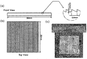
- FIG. 4 is a view of an aluminum substrate having a ratchet structure formed on an upper surface thereof.
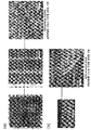
- FIG. 5 is a photograph of a super water-repellent hierarchical structure according to the preparation example.
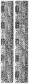
- Figure 6 is a photograph of the movement of the water droplets in the super water-repellent layer structure according to the preparation example.
- first, second, etc. may be used to describe various elements, components, regions, layers, and / or regions, such elements, components, regions, layers, and / or regions It will be understood that it should not be limited by these terms.
- the term "ultra water-repellent" used in the present invention means a water-repellent property having a contact angle of 150 ° or more and a sliding angle of 10 ° or less.
- the above-mentioned 'contact angle' refers to the angle between the liquid surface and the solid surface where the stationary liquid surface is in contact with the solid wall.
- the above-described 'slip angle' refers to the inclination angle at which the liquid starts to flow based on the horizontal bottom surface.
- the super water-repellent layer structure may include a substrate having a ratchet structure formed on an upper surface thereof and a super water-repellent nanowire structure formed on the ratchet structure.
- the water droplets on the substrate is characterized in that the movement in one direction without an external force. Furthermore, even when the surface of the substrate is inclined at 5 ° or less (almost without tilting the surface), water droplets on the substrate can be moved in one direction without external force.
- the substrate may be any material as long as it is a material capable of forming a ratchet structure on the upper surface.
- the ratchet structure at this time is characterized in that the absolute value of W 2 -W 1 is 50 ° or more, the height of the triangle forming the ratchet shape satisfies the condition of 100 ⁇ m to 400 ⁇ m, W 1 is a ratchet shape W 2 is the angle of the other of the two lower angles of the triangle forming a ratchet shape.
- the water droplets have a weak force from the ratchet structure and the substrate surface is hardly tilted, for example, the substrate surface is tilted to 5 ° or less. In a state, it may be difficult to behave in one direction without an external force.
- the super water-repellent nanowire structure is formed on the ratchet structure. Therefore, by forming the super water-repellent nanowire structure on the ratchet structure, the water droplets can be behaved in one direction without the force applied from the outside in the state that the surface is almost inclined. This causes the water droplets to be forced in one direction in the ratchet structure, and together with the formation of a super water-repellent nanowire structure on the ratchet structure, the water droplets are increased as the force to push the water droplets off the surface by the super water-repellent nanowires. It can move in one direction without external force.
- the length of such a super water-repellent nanowire is 2 micrometers or more.
- the diameter of the super water-repellent nanowire end is preferably 200nm or less.
- the super water-repellent nanowire structure may include a material having water repellent properties.
- the material having such a water repellent property may include at least one of CuO, Cu 2 O, CeO 2 and Co 3 O 4 .
- the super water-repellent nanowire structure may be manufactured to exhibit a superwater-repellent property by first synthesizing a nanowire structure including a material having such a water repellent property, and then performing vacuum drying.
- the super water-repellent nanowire structure includes at least one of ZnO, TiO 2 , Fe 2 O 3 , Al 2 O 3 and SiO 2 , it may be water-repellent coating to exhibit super water-repellent properties.
- the water repellent coating may be coated using a fluorine-based or silane-based material.
- 1 is a diagram showing a triangle forming a ratchet shape.
- W 1 is an angle of any one of two lower angles of a triangle forming a ratchet shape
- W 2 is an angle of the other of two lower angles of a triangle forming a ratchet shape.
- the height of the triangle forming the ratchet shape is d
- the length of the lower side of the triangle is l.
- FIG. 2 is a view showing the principle of the force of the droplets in the ratchet structure.
- Equation 1 when the shape of the surface structure is the same as that of FIG. 2, the force applied to the water droplets from the surface structure is represented by Equation 1 below.
- Equation 1 As a result of Equation 1, it can be seen that the force F applied to the water droplets by the surface structure increases as the difference between W 1 and W 2 increases.
- FIG. 3 is a flowchart of a method of manufacturing a super water-repellent layered structure according to an embodiment of the present invention.
- a substrate in which a ratchet structure is formed on an upper surface is prepared (S100).
- the ratchet structure is characterized in that the absolute value of W 2 -W 1 is 50 ° or more, and the height of the triangle forming the ratchet shape satisfies a condition of 100 ⁇ m to 400 ⁇ m.
- W 1 is an angle of any one of two lower angles of a triangle forming a ratchet shape
- W 2 is an angle of the other one of two lower angles of a triangle forming a ratchet shape.
- Such a ratchet structure can be formed through, for example, Computerized Numerical Control (CNC) processing.
- CNC Computerized Numerical Control
- the super water-repellent nanowire structure can be formed through two methods.
- the step of forming a super water-repellent nanowire structure on the ratchet structure after forming the nanowire structure on the ratchet structure by using hydrothermal synthesis, chemical vapor deposition or electrochemical deposition method, the formed nanowire structure is fluorine-based
- the water repellent coating may be performed using a material or a silane-based material to form a super water-repellent nanowire structure.
- an aluminum substrate having a ratchet structure formed on its upper surface may be formed of cerium nitrate hexahydrate (Cerium (III) Nitrate Hexahydrate, Ce (NO 3 ) 3 ⁇ 6H 2 O) and urea (Urea, CO (NH 2 ) 2 ).
- the cerium oxide nanowires were grown on the ratchet structure by hydrothermal synthesis at 95 ° C. for 24 hours by immersion in the mixed cerium precursor mixture, followed by drying in a vacuum atmosphere at 190 ° C. for 1 hour to grow the cerium oxide super water-repellent nanowires. You can.
- the super water-repellent nanowire structure on the ratchet structure having the above-described specific conditions, even when the substrate surface is almost inclined, for example, when the substrate surface is inclined at 5 ° or less, the water droplets on the substrate are free of external force. It can behave in one direction.
- a super water repellent layered structure was prepared according to an embodiment of the present invention.
- an aluminum substrate having a ratchet structure formed on an upper surface thereof was prepared.
- FIG. 4 is a view of an aluminum substrate having a ratchet structure formed on an upper surface thereof.
- an angle W 1 of any one of the two lower angles of the triangle forming the ratchet shape is about 26.56 °
- an angle W 2 of the other two of the lower two angles of the triangle forming the ratchet shape is about 90 °. Therefore, the absolute value of W 2 -W 1 is about 64 °.
- the height d of the triangle forming the ratchet shape is 0.2 mm, and the length l of the lower side is 0.4 mm.
- a ratchet-shaped aluminum was added to a cobalt oxide precursor mixed solution in which cobalt nitrate hexahydrate (Co (NO 3 ) 2 ⁇ 6H 2 O) and urea (Urea, CO (NH 2 ) 2 ) were mixed.
- the substrate was immersed to form a cobalt oxide nanowire structure on the ratchet structure by hydrothermal synthesis at 95 ° C. for 12 hours, followed by drying in a vacuum atmosphere at 190 ° C. for 1 hour to grow the cobalt oxide superhydrophobic nanowire structure on the ratchet structure. I was.
- FIG. 5 is a photograph of a super water-repellent hierarchical structure according to the preparation example.
- FIG. 5 (a) is a top photo of the super water-repellent layer structure according to the manufacturing example and an enlarged picture thereof, referring to this, a top view of the substrate and when zoomed in, the cobalt oxide nanowire structure is grown on the ratchet structure. Can be.
- Figure 5 (b) is a side view of the super water-repellent layer structure and the enlarged picture thereof according to the manufacturing example, it can be seen that the cobalt oxide nanowire structure was grown on the ratchet structure.
- An aluminum substrate having a ratchet structure formed on an upper surface thereof was prepared.
- the angle W 1 of any of the lower two angles of the ratchet-shaped triangle is about 45 ° and the angle W 2 of the other of the lower two angles of the ratchet-shaped triangle is about 90 °. Therefore, the absolute value of W 2 -W 1 is about 45 °.
- the height d of the triangle forming the ratchet shape is 0.2 mm, and the length l of the lower side is 0.2 mm.
- Figure 6 is a photograph of the movement of the water droplets in the super water-repellent layer structure according to the preparation example.
- the super water-repellent nanowire structure is formed on the ratchet structure that satisfies the above-described ratchet shape condition, even if the substrate surface is inclined at 5 ° or less (the substrate surface is hardly inclined), water droplets can be formed without external force. It can be seen that the movement in one direction.
Landscapes
- Chemical & Material Sciences (AREA)
- Engineering & Computer Science (AREA)
- Materials Engineering (AREA)
- Organic Chemistry (AREA)
- Metallurgy (AREA)
- Chemical Kinetics & Catalysis (AREA)
- Inorganic Chemistry (AREA)
- Electrochemistry (AREA)
- General Chemical & Material Sciences (AREA)
- Mechanical Engineering (AREA)
- Wood Science & Technology (AREA)
- Life Sciences & Earth Sciences (AREA)
- Crystallography & Structural Chemistry (AREA)
- Thermal Sciences (AREA)
- Physics & Mathematics (AREA)
- Ceramic Engineering (AREA)
- Nanotechnology (AREA)
- Combustion & Propulsion (AREA)
- Silicon Compounds (AREA)
- Laminated Bodies (AREA)
- Application Of Or Painting With Fluid Materials (AREA)
Abstract
초발수 계층 구조체를 제공한다. 초발수 계층 구조체는 상부 표면에 래칫(ratchet) 구조가 형성된 기판 및 상기 래칫 구조 상에 형성된 초발수 나노선 구조체를 포함하고, 상기 기판 상에서 물방울이 외부 힘 없이 일방향으로 거동이 가능한 것을 특징으로 한다. 따라서, 래칫구조와 초발수 나노선 구조체를 이용하여 표면이 거의 기울어지지 않은 상태에서, 외부에서 가해주는 힘 없이도 물방울을 일 방향으로 거동하게 할 수 있는 초발수 계층 구조체를 제공할 수 있다. 따라서, 이러한 초발수 계층 구조체를 이용하여 물 수확(water harvesting)이나 열교환기 등의 응축수 배수, 미세유체공학(microfluidic) 산업 등 다양한 산업에 적용 가능하다.
Description
본 발명은 초발수 계층 구조체에 관한 것으로, 표면에서 액적이 외부 힘 없이 일방향으로 거동이 가능한 초발수 계층 구조체 및 이의 제조방법에 관한 것이다.
최근 나비의 날개, 거미줄, 선인장의 가시 구조 등의 자연모사로부터 시작된, 물방울을 한 방향으로 움직이게 하는 기술 연구는 물 수확(water harvesting)이나 열교환기 등에서의 응축수 배수 또는 미세유체공학(microfluidic) 산업에서 주목받고 있는 기술이다.
하지만, 지금까지의 한 방향으로 물방울을 움직이게 하는데 있어서, 물질 표면에 물방울의 한 방향 거동을 위한 나노 또는 마이크로 구조체를 만든 경우, 표면을 기울였을 때, 한 방향으로 물방울이 굴러떨어짐 현상을 구현하거나, 자기장, 진동 등에 의해 여기된 힘을 외부에서 가함으로써 물방울을 한 방향으로 굴러 떨어뜨릴 수 있었다.
대한민국 공개특허 제10-2010-0011213(2010.02.03.)에서는 초소수성 표면을 갖는 재료의 제조방법 및 이에 따라 제조된 초소수성 재료에 관하여 개시되었으나, 표면이 거의 기울어지지 않은 상태에서, 외부힘 없이 물방울을 일 방향으로 거동시킬 수 있는 구조에 대하여는 개시된 바 없다.
따라서, 이와 같이, 표면을 기울이지 않고, 외부 힘 없이도 물방울을 한 방향으로 거동 가능할 수 있는 구조에 대한 연구가 필요하다.
본 발명이 해결하고자 하는 과제는, 표면이 거의 기울어지지 않은 상태에서, 외부에서 가해주는 힘 없이도 물방울을 일 방향으로 거동하게 할 수 있는 초발수 계층 구조체 및 이의 제조방법을 제공하는 데에 있다.
상기 과제를 이루기 위하여 본 발명의 일 측면은, 표면에서 액적이 일방향으로 거동이 가능한 초발수 계층 구조체를 제공한다. 이러한 초발수 계층 구조체는 상부 표면에 래칫(ratchet) 구조가 형성된 기판 및 상기 래칫 구조 상에 형성된 초발수 나노선 구조체를 포함하고, 상기 기판 상에서 물방울이 외부 힘 없이 일방향으로 거동이 가능한 것을 특징으로 한다.
또한, 상기 기판 표면을 5° 이하로 기울인 상태에서도, 상기 기판 상에서 물방울이 외부 힘 없이 일방향으로 거동이 가능한 것을 특징으로 한다.
또한, 상기 래칫 구조는 W2 - W1의 절대값이 50° 이상이고, 래칫 형상을 이루는 삼각형의 높이는 100㎛ 내지 400㎛인 조건을 만족하는 것을 특징으로 하고, 상기 W1은 래칫 형상을 이루는 삼각형의 하부 두 개의 각 중 어느 하나의 각이고, 상기 W2는 래칫 형상을 이루는 삼각형의 하부 두 개의 각 중 다른 하나의 각이다.
또한, 상기 초발수 나노선 구조체는 CuO, Cu2O, CeO2 및 Co3O4 중 적어도 하나를 포함할 수 있고, 상기 초발수 나노선 구조체는 나노선 구조체 합성 후, 진공건조를 통해 초발수 특성이 구현된 것을 특징으로 한다.
또한, 상기 초발수 나노선 구조체는 ZnO, TiO2, Fe2O3, Al2O3 및 SiO2 중 적어도 하나를 포함하고, 상기 초발수 나노선 구조체는 발수 코팅된 것을 특징으로 한다. 이때의 발수 코팅은 불소계 또는 실란계 물질을 이용하여 코팅하는 것을 특징으로 한다.
상기 과제를 이루기 위하여 본 발명의 다른 측면은 초발수 계층 구조체 제조방법을 제공한다. 이러한 초발수 계층 구조체 제조방법은 상부 표면에 래칫(ratchet) 구조가 형성된 기판을 준비하는 단계 및 상기 래칫 구조 상에 초발수 나노선 구조체를 형성하는 단계를 포함하고, 상기 기판 표면을 5° 이하로 기울인 상태에서도, 상기 기판 상에서 물방울이 외부 힘 없이 일방향으로 거동이 가능한 것을 특징으로 한다.
또한, 상기 래칫 구조는 W2 - W1의 절대값이 50° 이상이고, 래칫 형상을 이루는 삼각형의 높이는 100㎛ 내지 400㎛인 조건을 만족하는 것을 특징으로 하고, 상기 W1은 래칫 형상을 이루는 삼각형의 하부 두 개의 각 중 어느 하나의 각이고, 상기 W2는 래칫 형상을 이루는 삼각형의 하부 두 개의 각 중 다른 하나의 각이다.
또한, 상기 래칫 구조 상에 초발수 나노선 구조체를 형성하는 단계는, 상기 래칫 구조 상에 수열합성법, 화학기상증착법 또는 전기화학증착법을 이용하여 나노선 구조체를 형성한 후, 상기 형성된 나노선 구조체를 불소계 물질 또는 실란계 물질을 이용하여 발수코팅하거나, 진공건조를 수행하여 초발수 나노선 구조체를 형성하는 것을 특징으로 한다.
본 발명에 따르면, 래칫구조와 초발수 나노선 구조체를 이용하여 표면이 거의 기울어지지 않은 상태에서, 외부에서 가해주는 힘 없이도 물방울을 일 방향으로 거동하게 할 수 있는 초발수 계층 구조체를 제공할 수 있다.
따라서 이러한 초발수 계층 구조체를 이용하여 물 수확(water harvesting)이나 열교환기 등의 응축수 배수, 미세유체공학(microfluidic) 산업 등 다양한 산업에 적용 가능하다.
본 발명의 기술적 효과들은 이상에서 언급한 것들로 제한되지 않으며, 언급되지 않은 또 다른 기술적 효과들은 아래의 기재로부터 당업자에게 명확하게 이해될 수 있을 것이다.
도 1은 래칫 형상을 이루는 삼각형을 나타낸 그림이다.
도 2는 래칫 구조에서 물방울이 받는 힘의 원리를 나타낸 그림이다.
도 3은 본 발명의 일 실시예에 따른 초발수 계층 구조체 제조방법의 흐름도이다.
도 4는 상부 표면에 래칫구조가 형성된 알루미늄 기판의 도면들이다.
도 5는 제조예에 따른 초발수 계층 구조체의 사진들이다.
도 6은 제조예에 따른 초발수 계층 구조체에서의 물방울의 움직임을 측정한 사진들이다.
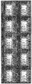
도 7은 비교예에 따른 초발수 계층 구조체에서의 물방울의 움직임을 측정한 사진들이다.
이하, 첨부된 도면을 참고하여 본 발명에 의한 실시예를 상세히 설명하면 다음과 같다.
본 발명이 여러 가지 수정 및 변형을 허용하면서도, 그 특정 실시예들이 도면들로 예시되어 나타내어지며, 이하에서 상세히 설명될 것이다. 그러나 본 발명을 개시된 특별한 형태로 한정하려는 의도는 아니며, 오히려 본 발명은 청구항들에 의해 정의된 본 발명의 사상과 합치되는 모든 수정, 균등 및 대용을 포함한다.
층, 영역 또는 기판과 같은 요소가 다른 구성요소 "상(on)"에 존재하는 것으로 언급될 때, 이것은 직접적으로 다른 요소 상에 존재하거나 또는 그 사이에 중간 요소가 존재할 수도 있다는 것을 이해할 수 있을 것이다.
비록 제1, 제2 등의 용어가 여러 가지 요소들, 성분들, 영역들, 층들 및/또는 지역들을 설명하기 위해 사용될 수 있지만, 이러한 요소들, 성분들, 영역들, 층들 및/또는 지역들은 이러한 용어에 의해 한정되어서는 안 된다는 것을 이해할 것이다.
또한, 본 발명에서 사용하는 용어 ‘초발수’의 의미는 접촉각(contact angle)이 150°이상이며, 미끄럼각(sliding angle)이 10°이하인 발수 특성을 의미한다. 이 때, 전술된 ‘접촉각’은 정지한 액체 표면이 고체 벽에 접촉되는 곳으로 액면과 고체면이 이루는 각을 말한다. 또한, 전술된 ‘미끄럼각’은 수평한 바닥면을 기준으로 액체가 흐르기 시작하는 기울기 각도를 의미한다.
본 발명의 일 실시예에 따른 초발수 계층 구조체를 설명한다.
이러한 초발수 계층 구조체는 상부 표면에 래칫(ratchet) 구조가 형성된 기판 및 상기 래칫 구조 상에 형성된 초발수 나노선 구조체를 포함할 수 있다. 이때, 상기 기판 상에서 물방울이 외부 힘 없이 일방향으로 거동이 가능한 것을 특징으로 한다. 나아가, 상기 기판 표면을 5° 이하로 기울인 상태(거의 표면을 기울이지 않은 상태)에서도, 상기 기판 상에서 물방울이 외부 힘 없이 일방향으로 거동이 가능한 것을 특징으로 한다.
이때의 기판은 상부 표면에 래칫 구조를 형성할 수 있는 물질이면 제한없이 가능할 것이다.
또한, 이때의 래칫 구조는 W2 - W1의 절대값이 50° 이상이고, 래칫 형상을 이루는 삼각형의 높이는 100㎛ 내지 400㎛인 조건을 만족하는 것을 특징으로 하고, 상기 W1은 래칫 형상을 이루는 삼각형의 하부 두 개의 각 중 어느 하나의 각이고, 상기 W2는 래칫 형상을 이루는 삼각형의 하부 두 개의 각 중 다른 하나의 각이다.
만일 래칫 구조에서 W2 - W1의 절대값이 50° 미만인 경우, 물방울이 래칫 구조로부터 받는 힘이 약하여 상기 기판 표면이 거의 기울어지지 않은 상태, 예를 들어, 기판 표면이 5° 이하로 기울어진 상태에서는, 외부 힘 없이 일방향으로 거동하기 곤란할 수 있다.
초발수 나노선 구조체는 래칫 구조 상에 형성된다. 따라서, 래칫 구조 상에 초발수 나노선 구조체를 형성함으로써 표면이 거의 기울어지지 않은 상태에서, 외부에서 가해주는 힘 없이도 물방울을 일 방향으로 거동하게 할 수 있다. 이는 래칫 구조에서 물방울이 일 방향으로 힘을 받게 되는데, 이와 더불어 래칫 구조 상에 초발수 나노선 구조체가 형성됨으로써, 이러한 초발수 나노선에 의해 표면에서 물방울을 밀어내려는 힘이 커짐에 따라, 물방울이 외부 힘 없이도 일방향으로 거동을 할 수 있게 된다.
이러한 초발수 나노선의 길이는 2㎛ 이상인 것이 바람직하다. 또한, 이러한 초발수 나노선 끝단의 직경은 200㎚ 이하인 것이 바람직하다.
이때의 초발수 나노선 구조체는 발수특성을 갖는 물질을 포함할 수 있다. 예를 들어, 이러한 발수특성을 갖는 물질은 CuO, Cu2O, CeO2 및 Co3O4 중 적어도 하나를 포함할 수 있다. 이때의 초발수 나노선 구조체는 먼저 이러한 발수특성을 갖는 물질을 포함하는 나노선 구조체를 합성 후, 진공건조를 수행하여 초발수 특성을 나타내도록 제조될 수 있다.
또한, 초발수 나노선 구조체는 ZnO, TiO2, Fe2O3, Al2O3 및 SiO2 중 적어도 하나를 포함하고, 발수 코팅되어 초발수 특성을 나타낼 수 있다. 이때의 발수 코팅은 불소계 또는 실란계 물질을 이용하여 코팅할 수 있다.
이하, 래칫 구조 및 레칫 구조에 의해 물방울이 받는 힘의 원리에 대하여 도 1 및 도 2를 통하여 설명한다.
도 1은 래칫 형상을 이루는 삼각형을 나타낸 그림이다.
도 1을 참조하면 W1은 래칫 형상을 이루는 삼각형의 하부 두 개의 각 중 어느 하나의 각이고, W2는 래칫 형상을 이루는 삼각형의 하부 두 개의 각 중 다른 하나의 각이다.
또한, 래칫 형상을 이루는 삼각형의 높이는 d이고, 삼각형의 하부 변의 길이는 l이다.
도 2는 래칫 구조에서 물방울이 받는 힘의 원리를 나타낸 그림이다.
도 2를 참조하면, 표면 구조의 형상이 도 2와 같을 때, 표면구조로부터 물방울에 가해지는 힘은 하기 식 1과 같다.
[식 1]

식 1의 결과, 표면 구조에 의해 물방울에 가해지는 힘(F)은 W1과 W2의 차이가 증가할수록 커짐을 알 수 있다.
따라서, W2 - W1의 절대값이 50° 이상이고, 래칫 형상을 이루는 삼각형의 높이는 100㎛ 내지 400㎛인 조건을 만족하는 래칫 구조 상에 초발수 나노 구조체를 형성함으로써, 기판 표면을 거의 기울이지 않은 상태, 예컨대, 기판 표면을 5° 이하로 기울인 상태에서도, 상기 기판 상에서 물방울이 외부 힘 없이 일방향으로 거동할 수 있다.
본 발명의 일 실시예에 따른 초발수 계층 구조체 제조방법을 설명한다.
도 3은 본 발명의 일 실시예에 따른 초발수 계층 구조체 제조방법의 흐름도이다.
도 3을 참조하면, 먼저, 상부 표면에 래칫(ratchet) 구조가 형성된 기판을 준비한다(S100).
이때의 래칫 구조는 W2 - W1의 절대값이 50° 이상이고, 래칫 형상을 이루는 삼각형의 높이는 100㎛ 내지 400㎛인 조건을 만족하는 것을 특징으로 한다. 그리고, 상기 W1은 래칫 형상을 이루는 삼각형의 하부 두 개의 각 중 어느 하나의 각이고, 상기 W2는 래칫 형상을 이루는 삼각형의 하부 두 개의 각 중 다른 하나의 각이다.
이러한 래칫 구조는 예를 들어, CNC(Computerized Numerical Control) 가공 등을 통하여 형성할 수 있다.
그 다음에, 상기 래칫 구조 상에 초발수 나노선 구조체를 형성한다(S200).
초발수 나노선 구조체는 두 가지 방법을 통하여 형성할 수 있다.
첫째, 래칫 구조 상에 초발수 나노선 구조체를 형성하는 단계는, 상기 래칫 구조 상에 수열합성법, 화학기상증착법 또는 전기화학증착법을 이용하여 나노선 구조체를 형성한 후, 상기 형성된 나노선 구조체를 불소계 물질 또는 실란계 물질을 이용하여 발수코팅하여 초발수 나노선 구조체를 형성할 수 있다.
둘째, 상기 방법과 동일한 방법으로 래칫 구조 상에 나노선 구조체를 형성한 후, 진공건조를 수행하여 초발수 나노선 구조체를 형성할 수 있다.
예를 들어, 상부 표면에 래칫 구조가 형성된 알루미늄 기판을 세륨 나이트레이트 헥사하이드레이트(Cerium(Ⅲ) Nitrate Hexahydrate, Ce(NO3)3·6H2O)와 요소(Urea, CO(NH2)2)를 혼합한 세륨전구체 혼합용액에 침지 하여 95℃에서 24시간 동안 수열합성법으로 래칫 구조 상에 산화세륨 나노선을 성장시킨 후, 190℃ 진공분위기에서 1시간 동안 건조하여 산화세륨 초발수 나노선을 성장시킬 수 있다.
따라서, 상술한 특정 조건을 갖는 래칫 구조 상에 초발수 나노선 구조체를 형성함으로써, 기판 표면을 거의 기울이지 않은 상태, 예컨대 상기 기판 표면을 5° 이하로 기울인 상태에서도, 상기 기판 상에서 물방울이 외부 힘 없이 일방향으로 거동할 수 있다.
제조예
본 발명의 일 실시예에 따른 초발수 계층 구조체를 제조하였다.
먼저 상부 표면에 래칫구조가 형성된 알루미늄 기판을 준비하였다.
도 4는 상부 표면에 래칫구조가 형성된 알루미늄 기판의 도면들이다.
도 4를 참조하면 래칫 형상을 이루는 삼각형의 하부 두 개의 각 중 어느 하나의 각(W1)은 약 26.56 ° 이고, 래칫 형상을 이루는 삼각형의 하부 두 개의 각 중 다른 하나의 각(W2)은 약 90°이다. 따라서, W2 - W1의 절대값은 약 64°이다.
그리고, 래칫 형상을 이루는 삼각형의 높이(d)는 0.2㎜이고, 하부변의 길이(l)는 0.4㎜이다.
그 다음에, 코발트 나이트레이트 헥사하이드레이트(Cobalt Nitrate Hexahydrate, Co(NO3)2·6H2O)와 요소(Urea, CO(NH2)2)를 혼합한 산화코발트 전구체 혼합용액에 래칫 형상의 알루미늄 기판을 침지하여 95℃에서 12시간 동안 수열합성법으로 래칫 구조 상에 산화코발트 나노선 구조체를 형성한 후, 190℃ 진공분위기에서 1시간 동안 건조하여 산화코발트 초발수 나노선 구조체를 래칫 구조 상에 성장시켰다.
도 5는 제조예에 따른 초발수 계층 구조체의 사진들이다.
도 5(a)를 참조하면 제조예 따른 초발수 계층 구조체의 상부 사진 및 이의 확대사진이고, 이를 참조하면, 기판의 상면 사진이고 이를 확대하면, 래칫 구조 상에 산화코발트 나노선 구조체가 성장되었음을 알 수 있다.
도 5(b)는 제조예 따른 초발수 계층 구조체의 측면 사진 및 이의 확대 사진이고, 이를 참조하면, 래칫 구조 상에 산화코발트 나노선 구조체가 성장되었음을 역시 알 수 있다.
비교예
상부 표면에 래칫구조가 형성된 알루미늄 기판을 준비하였다.
래칫 형상을 이루는 삼각형의 하부 두 개의 각 중 어느 하나의 각(W1)은 약 45° 이고, 래칫 형상을 이루는 삼각형의 하부 두 개의 각 중 다른 하나의 각(W2)은 약 90°이다. 따라서, W2 - W1의 절대값은 약 45°이다.
그리고, 래칫 형상을 이루는 삼각형의 높이(d)는 0.2㎜이고, 하부변의 길이(l)는 0.2㎜이다.
그 다음에, 이러한 래칫구조를 갖는 알루미늄 기판 상에 상술한 제조예와 동일한 방법으로 산화코발트 초발수 나노선 구조체를 형성하였다.
실험예
제조예 및 비교예에 따른 초발수 계층 구조체 상에 6㎕ 내지 8㎕ 물방울을 떨어뜨려 일방향으로의 거동 특성을 측정하였다. 이때, 기판 표면은 5° 이하로 기울어진 상태(거의 표면을 기울이지 않은 상태)이고, 외부 힘을 주지 않은 상태로 물방울의 거동 특성을 측정하였다.
도 6은 제조예에 따른 초발수 계층 구조체에서의 물방울의 움직임을 측정한 사진들이다.
도 6을 참조하면, 시간이 지남에 따라, 기판 표면이 거의 기울이지 않은 상태에서, 외부 힘 없이도 물방울이 일방향으로 움직이는 것을 알 수 있다.
도 7은 비교예에 따른 초발수 계층 구조체에서의 물방울의 움직임을 측정한 사진들이다.
도 7을 참조하면, 시간이 지나도, 기판 표면을 거의 기울이지 않은 상태이고, 외부의 힘이 없는 상태에서는 물방울이 거의 움직이지 않는 것을 알 수 있다.
따라서, 상술한 래칫 형상 조건을 만족하는 래칫구조 상에 초발수 나노선 구조체가 형성된 경우에, 기판 표면이 5° 이하로 기울어진 상태(기판 표면을 거의 기울이지 않은 상태)에서도, 외부 힘 없이도 물방울이 일방향으로 거동 가능함을 알 수 있다.
한편, 본 명세서와 도면에 개시된 본 발명의 실시 예들은 이해를 돕기 위해 특정 예를 제시한 것에 지나지 않으며, 본 발명의 범위를 한정하고자 하는 것은 아니다. 여기에 개시된 실시 예들 이외에도 본 발명의 기술적 사상에 바탕을 둔 다른 변형 예들이 실시 가능하다는 것은, 본 발명이 속하는 기술 분야에서 통상의 지식을 가진 자에게 자명한 것이다.
Claims (9)
- 상부 표면에 래칫(ratchet) 구조가 형성된 기판; 및상기 래칫 구조 상에 형성된 초발수 나노선 구조체를 포함하고,상기 기판 상에서 물방울이 외부 힘 없이 일방향으로 거동이 가능한 것을 특징으로 하는 초발수 계층 구조체.
- 제1항에 있어서,상기 기판 표면이 5° 이하로 기울어진 상태에서도, 상기 기판 상에서 물방울이 외부 힘 없이 일방향으로 거동이 가능한 것을 특징으로 하는 초발수 계층 구조체.
- 제1항에 있어서,상기 래칫 구조는 W2 - W1의 절대값이 50° 이상이고,래칫 형상을 이루는 삼각형의 높이는 100㎛ 내지 400㎛인 조건을 만족하는 것을 특징으로 하고,상기 W1은 래칫 형상을 이루는 삼각형의 하부 두 개의 각 중 어느 하나의 각이고, 상기 W2는 래칫 형상을 이루는 삼각형의 하부 두 개의 각 중 다른 하나의 각인 초발수 계층 구조체.
- 제1항에 있어서,상기 초발수 나노선 구조체는 CuO, Cu2O, CeO2 및 Co3O4 중 적어도 하나를 포함하고,상기 초발수 나노선 구조체는 나노선 구조체 합성 후, 진공건조를 통해 초발수 특성이 구현된 것을 특징으로 하는 초발수 계층 구조체.
- 제1항에 있어서,상기 초발수 나노선 구조체는 ZnO, TiO2, Fe2O3, Al2O3 및 SiO2 중 적어도 하나를 포함하고,상기 초발수 나노선 구조체는 발수 코팅된 것을 특징으로 하는 초발수 계층 구조체.
- 제5항에 있어서,상기 발수 코팅은 불소계 또는 실란계 물질을 이용하여 코팅하는 것은 특징으로 하는 초발수 계층 구조체.
- 상부 표면에 래칫(ratchet) 구조가 형성된 기판을 준비하는 단계; 및상기 래칫 구조 상에 초발수 나노선 구조체를 형성하는 단계를 포함하고,상기 기판 표면이 5° 이하로 기울어진 상태에서도, 상기 기판 상에서 물방울이 외부 힘 없이 일방향으로 거동이 가능한 것을 특징으로 하는 초발수 계층 구조체 제조방법.
- 제7항에 있어서,상기 래칫 구조는 W2 - W1의 절대값이 50° 이상이고,래칫 형상을 이루는 삼각형의 높이는 100㎛ 내지 400㎛인 조건을 만족하는 것을 특징으로 하고,상기 W1은 래칫 형상을 이루는 삼각형의 하부 두 개의 각 중 어느 하나의 각이고, 상기 W2는 래칫 형상을 이루는 삼각형의 하부 두 개의 각 중 다른 하나의 각인 초발수 계층 구조체 제조방법.
- 제7항에 있어서,상기 래칫 구조 상에 초발수 나노선 구조체를 형성하는 단계는,상기 래칫 구조 상에 수열합성법, 화학기상증착법 또는 전기화학증착법을 이용하여 나노선 구조체를 형성한 후, 상기 형성된 나노선 구조체를 불소계 물질 또는 실란계 물질을 이용하여 발수코팅하거나, 진공건조를 수행하여 초발수 나노선 구조체를 형성하는 것을 특징으로 하는 초발수 계층 구조체 제조방법.
Priority Applications (1)
| Application Number | Priority Date | Filing Date | Title |
|---|---|---|---|
| US15/323,209 US20170233586A1 (en) | 2014-07-01 | 2014-12-08 | Super water-repellent layer structure on which droplets can move in one direction and method for manufacturing same |
Applications Claiming Priority (2)
| Application Number | Priority Date | Filing Date | Title |
|---|---|---|---|
| KR10-2014-0081949 | 2014-07-01 | ||
| KR1020140081949A KR101470287B1 (ko) | 2014-07-01 | 2014-07-01 | 액적이 일방향으로 거동이 가능한 초발수 계층 구조체 및 이의 제조방법 |
Publications (1)
| Publication Number | Publication Date |
|---|---|
| WO2016003033A1 true WO2016003033A1 (ko) | 2016-01-07 |
Family
ID=52678061
Family Applications (1)
| Application Number | Title | Priority Date | Filing Date |
|---|---|---|---|
| PCT/KR2014/012008 Ceased WO2016003033A1 (ko) | 2014-07-01 | 2014-12-08 | 액적이 일방향으로 거동이 가능한 초발수 계층 구조체 및 이의 제조방법 |
Country Status (3)
| Country | Link |
|---|---|
| US (1) | US20170233586A1 (ko) |
| KR (1) | KR101470287B1 (ko) |
| WO (1) | WO2016003033A1 (ko) |
Cited By (1)
| Publication number | Priority date | Publication date | Assignee | Title |
|---|---|---|---|---|
| CN110424037A (zh) * | 2019-08-30 | 2019-11-08 | 北京石墨烯技术研究院有限公司 | 金属超疏水表面处理方法及产品 |
Families Citing this family (8)
| Publication number | Priority date | Publication date | Assignee | Title |
|---|---|---|---|---|
| WO2019150394A1 (en) | 2018-02-02 | 2019-08-08 | INDIAN INSTITUTE OF TECHNOLOGY MADRAS (IIT Madras) | A modified surface for condensation |
| CN109734325A (zh) * | 2019-02-20 | 2019-05-10 | 邹玉 | 一种超疏水防雾玻璃的制备方法 |
| CN110330894B (zh) * | 2019-03-20 | 2021-05-18 | 台州学院 | 一种用于汽车划痕修复的汽车车漆的制备方法 |
| CN110218098B (zh) * | 2019-04-30 | 2021-10-12 | 湖北大学 | 一种用于液体定向运输的图案化超疏液多孔膜的制备方法 |
| CN110791785B (zh) * | 2019-11-06 | 2020-10-16 | 山东科技大学 | 一种具有复合防腐功能的电沉积层-疏液-超滑三重膜及其制备方法和应用 |
| CN110685004B (zh) * | 2019-11-06 | 2020-07-28 | 山东科技大学 | 仿生免修饰超疏水Cu-Zn-CeO2层的制备方法及其应用 |
| CN113152075B (zh) * | 2021-05-25 | 2022-07-12 | 东莞理工学院 | 一种耐磨抗紫外抗静电超疏水织物及其制备方法 |
| CN117604766B (zh) * | 2024-01-24 | 2024-04-12 | 东华大学 | 一种高集水材料及其制备方法 |
Citations (4)
| Publication number | Priority date | Publication date | Assignee | Title |
|---|---|---|---|---|
| JP2005132919A (ja) * | 2003-10-29 | 2005-05-26 | Daikin Ind Ltd | 撥水性および滑水性に優れる表面処理用組成物 |
| JP2011057528A (ja) * | 2009-09-14 | 2011-03-24 | Nihon Univ | 滑水性皮膜及び表面滑水性部材 |
| KR20120047690A (ko) * | 2010-11-04 | 2012-05-14 | 한양대학교 산학협력단 | 나노입자들을 갖는 발수층 및 그 제조방법 |
| KR20130116431A (ko) * | 2012-03-19 | 2013-10-24 | 한국기계연구원 | 초발수 특성을 가진 금속 표면 구조 및 이의 형성 방법 |
-
2014
- 2014-07-01 KR KR1020140081949A patent/KR101470287B1/ko active Active
- 2014-12-08 US US15/323,209 patent/US20170233586A1/en not_active Abandoned
- 2014-12-08 WO PCT/KR2014/012008 patent/WO2016003033A1/ko not_active Ceased
Patent Citations (4)
| Publication number | Priority date | Publication date | Assignee | Title |
|---|---|---|---|---|
| JP2005132919A (ja) * | 2003-10-29 | 2005-05-26 | Daikin Ind Ltd | 撥水性および滑水性に優れる表面処理用組成物 |
| JP2011057528A (ja) * | 2009-09-14 | 2011-03-24 | Nihon Univ | 滑水性皮膜及び表面滑水性部材 |
| KR20120047690A (ko) * | 2010-11-04 | 2012-05-14 | 한양대학교 산학협력단 | 나노입자들을 갖는 발수층 및 그 제조방법 |
| KR20130116431A (ko) * | 2012-03-19 | 2013-10-24 | 한국기계연구원 | 초발수 특성을 가진 금속 표면 구조 및 이의 형성 방법 |
Cited By (2)
| Publication number | Priority date | Publication date | Assignee | Title |
|---|---|---|---|---|
| CN110424037A (zh) * | 2019-08-30 | 2019-11-08 | 北京石墨烯技术研究院有限公司 | 金属超疏水表面处理方法及产品 |
| CN110424037B (zh) * | 2019-08-30 | 2020-09-11 | 北京石墨烯技术研究院有限公司 | 金属超疏水表面处理方法及产品 |
Also Published As
| Publication number | Publication date |
|---|---|
| US20170233586A1 (en) | 2017-08-17 |
| KR101470287B1 (ko) | 2014-12-08 |
Similar Documents
| Publication | Publication Date | Title |
|---|---|---|
| WO2016003033A1 (ko) | 액적이 일방향으로 거동이 가능한 초발수 계층 구조체 및 이의 제조방법 | |
| CN103079989B (zh) | 有孔可渗透薄膜及其制备方法 | |
| US20050112051A1 (en) | Systems and methods for producing single-walled carbon nanotubes (SWNTS) on a substrate | |
| WO2017018674A1 (ko) | 나노 기공, 메조 기공 및 마크로 기공이 3차원적으로 상호 연결된 다공성 산화물 반도체, 그 제조방법 및 이를 가스감응물질로 포함하는 가스센서 | |
| WO2014123376A1 (ko) | 초발수/초발유 구조물 및 그의 제조 방법 | |
| US20100279066A1 (en) | Nanostructured thin film and method for controlling surface properties thereof | |
| WO2018216952A1 (ko) | 그래핀-산화주석 나노 복합체의 제조 방법 및 그래핀-산화주석 나노 복합체 | |
| WO2005094231A2 (en) | Methods for fabrication of positional and compositionally controlled nanostructures on substrate | |
| US10643842B2 (en) | Method for making patterned 2D transition metal dichalcogenides nanomaterials | |
| KR101438184B1 (ko) | 미세입자의 계면 자기조립 현상을 이용한 대면적 필름 및 그 제조방법 | |
| KR20210096039A (ko) | 용액 공정 가능한 탄소 동소체를 포함하는 하드 마스크 조성물, 이 조성물을 이용하여 하드마스크를 제조하는 방법 및 하드마스크 | |
| WO2010082733A2 (ko) | 열전 나노와이어 및 그의 제조방법 | |
| WO2016076563A1 (ko) | 그래핀 나노 패턴 인쇄 방법,그에 사용되는 장치 및 잉크 | |
| Fei et al. | Chemical Solution Deposition of Epitaxial Metal‐Oxide Nanocomposite Thin Films | |
| CN104194018B (zh) | 一种以蜂窝状多孔膜为模版构筑功能性有序多孔膜的方法 | |
| Bao et al. | Large‐Scale Controllable Patterning Growth of Aligned Organic Nanowires through Evaporation‐Induced Self‐Assembly | |
| Haque et al. | Remote epitaxy-based atmospherically stable hybrid graphene template for fast and versatile transfer of complex ferroelectric oxides onto Si | |
| US20160158706A1 (en) | Micro-and/or nano-scale patterned porous membranes, methods of making membranes, and methods of using membranes | |
| KR20090056038A (ko) | 표면 개질형 나노선 센서 및 그 제작 방법 | |
| Bechelany et al. | Rayleigh instability induced SiC/SiO 2 necklace like nanostructures | |
| Yang et al. | Highly ordered Pb (Zr0. 52Ti0. 48) O3 piezoelectric nanorod arrays | |
| WO2010140789A9 (ko) | 나노 디바이스 | |
| KR101029995B1 (ko) | 대전된 물질을 이용한 1 차원 또는 2 차원 전도성 나노선의 고집적 방법 및 그에 의한 전도성 집적 나노선 | |
| KR101535390B1 (ko) | 초발수 폴리머 계층구조체 및 그 제조방법 | |
| WO2019013603A1 (ko) | 고분자 막의 분석 방법 |
Legal Events
| Date | Code | Title | Description |
|---|---|---|---|
| 121 | Ep: the epo has been informed by wipo that ep was designated in this application |
Ref document number: 14896884 Country of ref document: EP Kind code of ref document: A1 |
|
| NENP | Non-entry into the national phase |
Ref country code: DE |
|
| 122 | Ep: pct application non-entry in european phase |
Ref document number: 14896884 Country of ref document: EP Kind code of ref document: A1 |