WO2016002823A1 - Récepteur de collecte de chaleur - Google Patents
Récepteur de collecte de chaleur Download PDFInfo
- Publication number
- WO2016002823A1 WO2016002823A1 PCT/JP2015/068924 JP2015068924W WO2016002823A1 WO 2016002823 A1 WO2016002823 A1 WO 2016002823A1 JP 2015068924 W JP2015068924 W JP 2015068924W WO 2016002823 A1 WO2016002823 A1 WO 2016002823A1
- Authority
- WO
- WIPO (PCT)
- Prior art keywords
- air
- connection hole
- heat collecting
- honeycomb body
- collecting receiver
- Prior art date
Links
Images


Classifications
-
- F—MECHANICAL ENGINEERING; LIGHTING; HEATING; WEAPONS; BLASTING
- F24—HEATING; RANGES; VENTILATING
- F24S—SOLAR HEAT COLLECTORS; SOLAR HEAT SYSTEMS
- F24S10/00—Solar heat collectors using working fluids
- F24S10/80—Solar heat collectors using working fluids comprising porous material or permeable masses directly contacting the working fluids
-
- F—MECHANICAL ENGINEERING; LIGHTING; HEATING; WEAPONS; BLASTING
- F24—HEATING; RANGES; VENTILATING
- F24S—SOLAR HEAT COLLECTORS; SOLAR HEAT SYSTEMS
- F24S20/00—Solar heat collectors specially adapted for particular uses or environments
- F24S20/20—Solar heat collectors for receiving concentrated solar energy, e.g. receivers for solar power plants
-
- F—MECHANICAL ENGINEERING; LIGHTING; HEATING; WEAPONS; BLASTING
- F24—HEATING; RANGES; VENTILATING
- F24S—SOLAR HEAT COLLECTORS; SOLAR HEAT SYSTEMS
- F24S70/00—Details of absorbing elements
- F24S70/10—Details of absorbing elements characterised by the absorbing material
- F24S70/16—Details of absorbing elements characterised by the absorbing material made of ceramic; made of concrete; made of natural stone
-
- Y—GENERAL TAGGING OF NEW TECHNOLOGICAL DEVELOPMENTS; GENERAL TAGGING OF CROSS-SECTIONAL TECHNOLOGIES SPANNING OVER SEVERAL SECTIONS OF THE IPC; TECHNICAL SUBJECTS COVERED BY FORMER USPC CROSS-REFERENCE ART COLLECTIONS [XRACs] AND DIGESTS
- Y02—TECHNOLOGIES OR APPLICATIONS FOR MITIGATION OR ADAPTATION AGAINST CLIMATE CHANGE
- Y02E—REDUCTION OF GREENHOUSE GAS [GHG] EMISSIONS, RELATED TO ENERGY GENERATION, TRANSMISSION OR DISTRIBUTION
- Y02E10/00—Energy generation through renewable energy sources
- Y02E10/40—Solar thermal energy, e.g. solar towers
- Y02E10/44—Heat exchange systems
Definitions
- the present invention relates to a heat collecting receiver that receives sunlight and converts it into heat.
- Solar thermal power generation includes tower-type solar thermal power generation that uses a mirror having a sun tracking function to concentrate sunlight on a heat collecting receiver provided in the tower.
- Tower-type solar power generation is characterized by high temperature and high energy efficiency because light from many mirrors is collected in one place.
- the heat collecting receiver used for the tower type solar thermal power generation has been devised in various ways such as material and structure.
- Patent Document 1 heat exchange is performed on air that has passed through the heat collection receiver and the temperature has risen, and part or all of the air that has fallen in temperature is returned to the front surface of the heat collection receiver using a branch pipe.
- a structure of a heat collecting receiver adapted to be sucked has been proposed.
- the heat collecting receiver described in Patent Document 1 includes a pipe used for returning air whose temperature has been lowered from the branch pipe to the light receiving surface of the heat collecting receiver in the absorber.
- the pipe that returns the low-temperature air to the front surface of the absorber is used for transporting the air in a long section and reaches the surface of the light-receiving portion, so that it is necessary to have both heat resistance and strength at the same time.
- the pipe used for returning air needs to use a material having high strength and heat resistance.
- a dense and thick material is desirable to maintain strength, while a thin and porous material is preferred to mitigate thermal shock.
- a material having high heat resistance is not necessarily a material having high strength, and what kind of air return pipe is provided is important in designing a heat collecting receiver. That is, by providing a pipe that returns air, the heat resistance and strength of the heat collecting receiver are reduced.
- an object of the present invention is to provide a heat collecting receiver that has a function of returning air and that can sufficiently exhibit the heat resistance and strength of a honeycomb body and can be used stably.
- the heat collecting receiver of the present invention for solving the above-described problems includes an absorber having a light-receiving surface that absorbs sunlight, a first connection hole, and a second connection hole while holding the absorber.
- a heat collecting receiver comprising a housing, wherein the absorber includes a plurality of honeycomb bodies separated from each other by a gap opened on the light receiving surface side, and a partition wall through which each honeycomb body passes, One connection hole communicates with the light receiving surface via the honeycomb body, and the second connection hole communicates with the light receiving surface via the gap.
- the heat collecting receiver of the present invention since it comprises an absorber that absorbs sunlight and a housing that holds the absorber, the heat absorbed by the absorber is taken into the housing and is not leaked to the outside. can do.
- the housing is provided with a first connection hole and a second connection hole, and air in opposite directions flows through the first connection hole and the second connection hole. For this reason, the air heated from one connection hole can be sucked and the used air can be returned from the other connection hole.
- the flow path extending from the first connection hole communicates with the light receiving surface via the honeycomb body, and the second connection hole communicates with the light receiving surface via the gap. For this reason, the air which received light and was heated up is attracted
- the partition wall separates the front space on the light receiving surface side and the rear space on the opposite side. Since the separated air is separated by the partition wall, the returned air that is not sufficiently cooled is sufficiently reheated via the light receiving surface of the absorber and then sucked into the generator side.
- the air can be sufficiently warmed, and the thermal efficiency can be increased.
- the absorbent body is composed only of the honeycomb bodies, and air that is not sufficiently cooled to the light receiving surface can be returned using the gaps between the honeycomb bodies.
- a heat collecting receiver can be configured without being restricted by shape, material, etc. Can do.
- the air flow is not limited to one direction, and it is also possible to return air that has not been sufficiently cooled from the honeycomb body and suck the warmed air from the gap. Accordingly, the heat collecting receiver has a function of returning air, and can sufficiently utilize the heat resistance and strength of the honeycomb body and can be stably used.
- the heat collecting receiver of the present invention has the following aspect.
- the second connection hole communicates with the light receiving surface via the side surface of the absorber and the gap.
- the air gap and the second connection hole communicate with each other through the side surface of the honeycomb body, that is, the intermediate portion between the partition wall and the light receiving surface, rather than the partition wall. Since the front space connected to the gap is drawn to the side of the absorber, the entire side surface of the honeycomb body can be used, and air can be efficiently returned to the light receiving surface even if the gap is narrow.
- the honeycomb body is made of ceramic. Since the honeycomb body is made of ceramic, the heat collecting receiver of the present invention has heat resistance and corrosion resistance and high strength. For this reason, it can be used even in a severe environment such as a high temperature environment or a corrosive environment.
- the honeycomb body is made of one or more ceramics selected from alumina, cordierite, silicon carbide, and aluminum titanate. Since the heat collecting receiver of the present invention is made of ceramic such as alumina, cordierite, silicon carbide, aluminum titanate, etc., it is possible to provide a heat collecting receiver having high heat resistance and corrosion resistance and high strength.
- the absorber constituting the heat collecting receiver has a plurality of honeycomb bodies separated from each other by a gap opened on the light receiving surface side, and a partition wall through which each honeycomb body passes.
- the flow path extending from the first connection hole communicates with the light receiving surface via the honeycomb body, and the second connection hole communicates with the light receiving surface via the gap.
- the heat collecting receiver has a function of returning air, and can sufficiently utilize the heat resistance and strength of the honeycomb body and can be stably used.
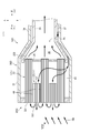
- FIG. 1 is a front view of a part of the receiver array
- B is a cross-sectional view taken along the line BB in (A).
- the heat collecting receiver of the present invention will be described.
- the heat collecting receiver of the present invention includes an absorber having a light receiving surface that absorbs sunlight, and a housing that holds the absorber and includes a first connection hole and a second connection hole.
- the absorber includes a plurality of honeycomb bodies separated from each other by a gap opened on the light receiving surface side, and a partition wall through which each honeycomb body passes, and the first connection hole includes the first connection hole,
- the second connecting hole communicates with the light receiving surface via the gap, and communicates with the light receiving surface via a honeycomb body.
- the heat collecting receiver of the present invention since it comprises an absorber that absorbs sunlight and a housing that holds the absorber, the heat absorbed by the absorber is taken into the housing and is not leaked to the outside. can do.
- the housing is provided with a first connection hole and a second connection hole, and air in opposite directions flows through the first connection hole and the second connection hole. For this reason, the air heated from one connection hole can be sucked and the used air can be returned from the other connection hole.
- the flow path extending from the first connection hole communicates with the light receiving surface via the honeycomb body, and the second connection hole communicates with the light receiving surface via the gap. For this reason, the air which received light and was heated up is attracted
- the partition wall separates the light receiving surface side, that is, the front space of the absorber, and the opposite side, that is, the rear space of the absorber.
- the absorbent body is composed only of the honeycomb bodies, and air that is not sufficiently cooled to the light receiving surface can be returned using the gaps between the honeycomb bodies. For this reason, since it is possible to configure an absorbent body made only of a honeycomb body having a function of returning air without using a special member, a heat collecting receiver can be configured without being restricted by shape, material, etc. Can do.
- the air flow is not limited to one direction, and it is also possible to return air that has not been sufficiently cooled from the honeycomb body and suck the warmed air from the gap. Accordingly, the heat collecting receiver has a function of returning air, and can sufficiently utilize the heat resistance and strength of the honeycomb body and can be stably used.
- the heat collecting receiver of the present invention has the following aspect.
- the second connection hole communicates with the light receiving surface via the side surface of the absorber and the gap.
- the air gap and the second connection hole communicate with each other via the side surface of the honeycomb body, that is, between the partition wall and the light receiving surface, rather than the partition wall. Since the front space connected to the gap is drawn to the side of the absorber, the entire side surface of the honeycomb body can be used, and air can be efficiently returned to the light receiving surface even if the gap is narrow.
- the honeycomb body is made of ceramic. Since the honeycomb body is made of ceramic, the heat collecting receiver of the present invention has heat resistance and corrosion resistance and high strength. For this reason, it can be used even in a severe environment such as a high temperature environment or a corrosive environment.
- the honeycomb body is made of one or more ceramics selected from alumina, cordierite, silicon carbide, and aluminum titanate. Since the heat collecting receiver of the present invention is made of ceramic such as alumina, cordierite, silicon carbide, aluminum titanate, etc., it is possible to provide a heat collecting receiver having high heat resistance and corrosion resistance and high strength.
- the heat collecting receiver 10 of each embodiment described below can be used for the power generation apparatus 1 using sunlight.
- the power generator 1 has a central tower 2 in the center.
- a receiver array 3 in which a plurality of heat collecting receivers 10 to be described later are accommodated is disposed at the highest position of the central tower 2.
- a steam generator 4 below the receiver array 3, a steam generator 4, a heat accumulator 5, and a steam turbine 6 are sequentially arranged.
- a number of heliostats 8 are arranged around the central tower 2.
- the heliostat 8 is set so that the reflection angle and the rotation direction around the vertical direction can be freely controlled.
- the heliostat 8 is automatically controlled so as to reflect the sunlight changing from moment to moment and collect it in the receiver array 3 of the central tower 2.
- a plurality of heat collecting receivers 10 are placed in a box with the sunlight irradiation surface open, and the light receiving surface that receives sunlight irradiation is in front. It is arranged in an aligned state.
- the heat collection receiver 10 high-temperature air heated by sunlight is sucked and the steam turbine 6 is driven, and then returned from the heat collection receiver 10 and returned to the outside.
- the heat collecting receiver 10 ⁇ / b> A of the first embodiment includes an absorber 20 ⁇ / b> A having a light receiving surface that absorbs sunlight SB reflected from the heliostat 8, and a housing that holds the absorber 20 ⁇ / b> A.
- the housing 30 ⁇ / b> A includes a housing portion 31 that houses the absorber 20 ⁇ / b> A, and pipes 33 and 34 that are continuous with the housing portion 31 and communicate with the steam generator 4 and the like.
- the absorbent body 20 ⁇ / b> A is formed by a plurality of honeycomb bodies 21 separated from each other by gaps 44.
- the absorbent body 20A houses a plurality of honeycomb bodies 21 in a housing portion 31 of a housing 30A having a square cross-sectional shape.
- a total of 25 honeycomb bodies 21 of 5 vertical ⁇ 5 horizontal are accommodated.
- the honeycomb body 21 is made of ceramic.
- the honeycomb body 21 is preferably made of, for example, one or more ceramics selected from alumina, cordierite, silicon carbide, and aluminum titanate.
- the gaps 44 between the plurality of honeycomb bodies 21 are open to the front (left side in FIG. 3) of the absorbent body 20A.
- the gap 44 is continuous with the housing part space 45 of the housing part 31 of the housing 30A.
- the accommodating space 45 is continuous with the second connection hole 27 provided between the pipe 33 and the pipe 34 provided outside the pipe 33. Therefore, the second connection hole 27 is opened to the front side of the absorbent body 20 ⁇ / b> C via the accommodating space 45 and the gap 44 on the honeycomb body 21 side of the partition wall 28.
- the outer end surface 211 of the honeycomb body 21 is a light receiving surface.
- An end portion on the inner end face 212 side of the honeycomb body 21 is supported by the partition wall 28, and the inner end face 212 is open to the rear space 26.
- the rear space 26 continues to the pipe 33 through the first connection hole 25. Therefore, the pipe 33 is open to the front of the absorbent body 20 ⁇ / b> C via the rear space 26 and the honeycomb body 21. Thereby, the air of the mutually opposite direction can distribute
- FIG. Note that the end portions on the outer end face 211 side of the honeycomb body 21 may be held at a constant interval and may not be locked to each other.
- the air illuminated by the sunlight SB from the heliostat 8 is sucked from the outer end surface 211 of the honeycomb body 21 and accommodated in the rear space 26 of the absorber 20A from the inner end surface 212.
- the air accommodated in the rear space 26 of the absorber 20A is sent to the steam generator 4 and the like through the first connection hole 25 by the pipe 33 and used for power generation.
- the air used for power generation passes through the pipe 34 and is sent from the second connection hole 27 to the accommodating portion space 45.
- the air sent to the housing space 45 is returned to the front side of the absorbent body 20 ⁇ / b> A from the gap 44 between the honeycomb bodies 21. A part of the returned air is sucked again from the outer end surface 211 of the honeycomb body 21 adjacent to the gap 44.
- the heat collecting receiver 10A of the first embodiment since the absorber 20A that absorbs sunlight and the housing 30A that holds the absorber 20A are included, the heat absorbed by the absorber 20A is taken into the housing 30A. It can be prevented from leaking outside.
- the housing 30A is provided with a first connection hole 25 and a second connection hole 27, and air in opposite directions flows through the first connection hole 25 and the second connection hole 27. ing. For this reason, the air heated from one connection hole can be sucked and the used air can be returned from the other connection hole.
- the absorbent body 20A isolates the plurality of honeycomb bodies 21 separated from each other by the gaps 44, the outer end face 211 as a light receiving surface in each honeycomb body 21, and the inner end face 212 on the opposite side to the outer end face 211. And a partition wall 28.
- the flow path extending from the first connection hole 25 communicates with the outer end surface 211 via the honeycomb body 21, and the second connection hole 27 communicates with the light receiving surface via the gap 44. For this reason, the air that has received light and has been heated is sucked from the outer end face 211, passes through the honeycomb body 21, and is sent from the inner end face 212 to the inside of the partition wall 28.
- the used air is sent from the second connection hole 27 to the gap 44 between the adjacent honeycomb bodies 21 and is returned from the light receiving surface through the gap 44.
- the partition 28 separates the light receiving surface side, that is, the front space of the absorber 20A, that is, the housing space 45, and the opposite side, that is, the rear space 26 of the absorber 20A. Since the separated air is separated by the partition wall 28, the returned air that is not sufficiently cooled is sufficiently reheated via the light receiving surface of the absorber 20A and then sucked to the generator side. For this reason, the air can be sufficiently warmed, and the thermal efficiency can be increased.
- the absorbent body 20A is composed only of the honeycomb bodies 21 and can return air that has not been sufficiently cooled to the light receiving surface using the gaps 44 between the honeycomb bodies 21. For this reason, since it is possible to configure the absorbent body 20A composed only of the honeycomb body 21 having a function of returning air without using a special member, the heat collecting receiver 10A can be configured without being restricted by shape, material, and the like. Can be configured. Note that the air flow is not limited to one direction, and it is also possible to return air that has not been sufficiently cooled from the honeycomb body 21 and suck the warmed air from the gap 44. Accordingly, the heat collecting receiver 10A has a function of returning air, and can sufficiently utilize the heat resistance and strength of the honeycomb body 21 and can be stably used.
- the air gap 44 and the second connection hole 27 communicate with each other via the side surface of the honeycomb body 21, that is, between the partition wall 28 and the light receiving surface, rather than the partition wall 28. Since the accommodating space 45 connected to the gap 44 is pulled out to the side of the absorbent body 20A, the entire side surface of the honeycomb body 21 can be used, and even if the gap 44 is narrow, the air is efficiently returned to the light receiving surface. be able to.
- the honeycomb body 21 is made of ceramic, it has heat resistance and corrosion resistance, and has high strength. For this reason, it can be used even in a severe environment such as a high temperature environment or a corrosive environment.
- the heat collecting receiver 10A of the first embodiment is made of ceramic such as alumina, cordierite, silicon carbide, aluminum titanate, etc., it is possible to provide a heat collecting receiver 10A having heat resistance and corrosion resistance and having high strength.
- the heat collecting receiver of 2nd Embodiment is demonstrated, using a figure.
- symbol is attached
- the pipe 35 is provided inside the housing 30 ⁇ / b> B housing the absorber 20 ⁇ / b> B and inside the pipe 33.
- the pipe 35 sends the used air.
- the tip of the pipe 35 passes through the partition wall 28 and continues to the gap 44 between the honeycomb bodies 21.
- the air illuminated by the sunlight SB from the heliostat 8 is sucked from the outer end surface 211 of the honeycomb body 21 and accommodated in the second rear space 26 from the inner end surface 212.
- the air accommodated in the second rear space 26 is sent to the steam generator 4 or the like by the pipe 33 through the first connection hole 25 and used for power generation.
- the air used for power generation passes through the pipe 35, is sent from the second connection hole 27 to the gap 44 between the honeycomb bodies 21, and is returned forward from the light receiving surface. A part of the returned air is sucked again from the outer end surface 211 of the honeycomb body 21 adjacent to the gap 44.
- the heat collecting receiver of 3rd Embodiment is demonstrated using a figure.
- symbol is attached
- the pipe 32 communicating with the first connection hole 25 is provided in the housing portion 31 of the housing 30 ⁇ / b> C that houses the absorber 20 ⁇ / b> C.
- the air illuminated by the sunlight SB from the heliostat 8 is sucked from the outer end surface 211 of the honeycomb body 21 and accommodated in the rear space 26 from the inner end surface 212.
- the air accommodated in the rear space 26 is sent to the steam generator 4 or the like by the pipe 33 through the second connection hole 27 and used for power generation.
- the air used for power generation passes through the pipe 32, is sent from the first connection hole 25 to the gap 44 between the honeycomb bodies 21, and is returned forward from the light receiving surface. A part of the returned air is sucked again from the outer end surface 211 of the honeycomb body 21 adjacent to the gap 44.
- the heat collecting receiver of 4th Embodiment is demonstrated, using a figure.
- symbol is attached
- the heat collection receiver 10D of the fourth embodiment includes an absorber 20D.
- the absorber 20D is accommodated in the housing 30A used in the first embodiment described above.
- the absorbent body 20D includes a plurality of honeycomb bodies 21 (22, 23) having a square cross-sectional shape.
- the honeycomb body 23 communicates with the second connection holes 27 without penetrating the partition walls 28. Therefore, the honeycomb body 22 communicates with the first connection hole 25, and the honeycomb body 22 communicates with the second connection hole 27.
- the honeycomb body 22 is the majority among the honeycomb bodies 21 (22, 23). Since the gaps 44 between the honeycomb bodies 21 (22, 23) communicate with the second connection holes 27, it is preferable that the honeycomb bodies 22 communicated with the first connection holes 25 be larger than the honeycomb bodies 23.
- the honeycomb body 22 that penetrates the partition walls 28 and the honeycomb body 23 that does not penetrate the partition walls 28 are formed of ceramics made of the same material. As shown in FIG. 7, the first connection hole 25 communicates with the light receiving surface via the honeycomb body 22 penetrating the partition wall 28, and the second connection hole 27 is a honeycomb that does not penetrate the void 44 and the partition wall 28. It communicates with the light receiving surface via the body 23.
- the air illuminated by the sunlight SB from the heliostat 8 is sucked from the outer end surface 221 of the honeycomb body 22 that penetrates the partition walls 28, passes through the partition walls 28, and is absorbed from the inner end surface 222. It is accommodated in the rear space 26 of 20D.
- the air accommodated in the rear space 26 of the absorber 20D is sent to the steam generator 4 and the like through the first connection hole 25 by the pipe 33 and used for power generation.
- the air used for power generation passes through the pipe 34 and is sent from the second connection hole 27 to the accommodating portion space 45.
- the air sent to the accommodating space 45 passes through the side surface of the honeycomb body 22, passes through the honeycomb body 23 that does not pass through the partition walls 28 from the inner end face 232 of the honeycomb body 23 that does not pass through the partition walls 28, and from the outer end face 231. Returned to the outside. At this time, air can be directly returned from the gap 44 between the honeycomb bodies 22 and 23 without penetrating the honeycomb body 23 that does not penetrate the partition walls 28. A part of the returned air is sucked again from the outer end surface 221 of the honeycomb body 22 that penetrates the partition walls 28.
- the heat collecting receiver of the present invention is not limited to the above-described embodiments, and appropriate modifications and improvements can be made.
- This application is based on a Japanese patent application filed on June 30, 2014 (Japanese Patent Application No. 2014-134584), the contents of which are incorporated herein by reference.
- the heat collecting receiver of the present invention can be used for a generator that generates power by receiving sunlight and converting it into heat.
Landscapes
- Engineering & Computer Science (AREA)
- Chemical & Material Sciences (AREA)
- Sustainable Development (AREA)
- Physics & Mathematics (AREA)
- Sustainable Energy (AREA)
- Thermal Sciences (AREA)
- Life Sciences & Earth Sciences (AREA)
- Combustion & Propulsion (AREA)
- Mechanical Engineering (AREA)
- General Engineering & Computer Science (AREA)
- Dispersion Chemistry (AREA)
- Ceramic Engineering (AREA)
- Laminated Bodies (AREA)
Abstract
L'invention concerne un récepteur de collecte de chaleur (10A), comprenant un corps d'absorption (20A), et un logement (30A) servant à maintenir le corps d'absorption (20A). Un premier trou de connexion (25) et un second trou de connexion (27) sont disposés dans le logement (30A). Le premier trou de connexion (25) et le second trou de connexion (27) sont configurés de façon à ce que l'air y circule selon des directions mutuellement inverses. Le corps d'absorption (20A) comprend : plusieurs corps alvéolés (21) séparés les uns des autres par des espaces (44) ; des surfaces de réception de lumière (211) disposées sur chaque corps alvéolé (21) ; et une paroi de séparation (28) servant à séparer des surfaces d'extrémité internes (212) au niveau du côté opposé aux surfaces de réception de lumière (211). Un chemin d'écoulement (33) s'étendant depuis le premier trou de connexion (25) communique avec les surfaces de réception de lumière (211) via les corps alvéolés (21).
Le second trou de connexion (27) communique avec les surfaces de réception de lumière (211) via les espaces (44).
Applications Claiming Priority (2)
| Application Number | Priority Date | Filing Date | Title |
|---|---|---|---|
| JP2014134584A JP2016011810A (ja) | 2014-06-30 | 2014-06-30 | 集熱レシーバ |
| JP2014-134584 | 2014-06-30 |
Publications (1)
| Publication Number | Publication Date |
|---|---|
| WO2016002823A1 true WO2016002823A1 (fr) | 2016-01-07 |
Family
ID=55019353
Family Applications (1)
| Application Number | Title | Priority Date | Filing Date |
|---|---|---|---|
| PCT/JP2015/068924 WO2016002823A1 (fr) | 2014-06-30 | 2015-06-30 | Récepteur de collecte de chaleur |
Country Status (2)
| Country | Link |
|---|---|
| JP (1) | JP2016011810A (fr) |
| WO (1) | WO2016002823A1 (fr) |
Cited By (1)
| Publication number | Priority date | Publication date | Assignee | Title |
|---|---|---|---|---|
| WO2020083972A1 (fr) * | 2018-10-23 | 2020-04-30 | Kraftanlagen München Gmbh | Module absorbeur |
Citations (3)
| Publication number | Priority date | Publication date | Assignee | Title |
|---|---|---|---|---|
| WO2003021160A1 (fr) * | 2001-09-06 | 2003-03-13 | Stobbe Tech Holding A/S | Ensemble recepteur volumetrique hybride et son procede de production |
| WO2004023048A1 (fr) * | 2002-09-06 | 2004-03-18 | Kraftanlagen Munchen Gmbh | Modules d'absorbeurs volumetriques ceramiques ou metalliques combines et simplifies |
| DE102004030433B3 (de) * | 2004-06-24 | 2005-08-11 | Deutsches Zentrum für Luft- und Raumfahrt e.V. | Solarempfänger |
-
2014
- 2014-06-30 JP JP2014134584A patent/JP2016011810A/ja active Pending
-
2015
- 2015-06-30 WO PCT/JP2015/068924 patent/WO2016002823A1/fr active Application Filing
Patent Citations (3)
| Publication number | Priority date | Publication date | Assignee | Title |
|---|---|---|---|---|
| WO2003021160A1 (fr) * | 2001-09-06 | 2003-03-13 | Stobbe Tech Holding A/S | Ensemble recepteur volumetrique hybride et son procede de production |
| WO2004023048A1 (fr) * | 2002-09-06 | 2004-03-18 | Kraftanlagen Munchen Gmbh | Modules d'absorbeurs volumetriques ceramiques ou metalliques combines et simplifies |
| DE102004030433B3 (de) * | 2004-06-24 | 2005-08-11 | Deutsches Zentrum für Luft- und Raumfahrt e.V. | Solarempfänger |
Cited By (1)
| Publication number | Priority date | Publication date | Assignee | Title |
|---|---|---|---|---|
| WO2020083972A1 (fr) * | 2018-10-23 | 2020-04-30 | Kraftanlagen München Gmbh | Module absorbeur |
Also Published As
| Publication number | Publication date |
|---|---|
| JP2016011810A (ja) | 2016-01-21 |
Similar Documents
| Publication | Publication Date | Title |
|---|---|---|
| US20100264656A1 (en) | Orbiting power plant | |
| WO2015193870A2 (fr) | Concentrateur parabolique à deux étages | |
| JP2016532842A (ja) | 太陽エネルギー収集器およびそれを用いたシステム{solar energy collector and system for using same} | |
| WO2013059112A1 (fr) | Système et procédé de production d'énergie hybride solaire/non solaire | |
| WO2016002823A1 (fr) | Récepteur de collecte de chaleur | |
| WO2011157799A1 (fr) | Ensemble capteur solaire pourvu d'au moins une liaison par clinchage, procédé de fabrication de l'ensemble capteur solaire par un mécanisme de clinchage et utilisation de l'ensemble capteur solaire | |
| US20160233829A1 (en) | Solar water-collecting, air-conditioning, light-transmitting and power generating house | |
| CN111287921A (zh) | 用于近海应用的高效太阳能发电机 | |
| AU2016243916B2 (en) | Solar power collection systems and methods thereof | |
| US10895406B1 (en) | Solar concentrator | |
| KR101293420B1 (ko) | 태양열 발전시스템 | |
| WO2016002822A1 (fr) | Récepteur collecteur de chaleur | |
| CN104236127B (zh) | 碟式太阳能热发电系统的热储存系统 | |
| WO2016002824A1 (fr) | Récepteur de collecte de chaleur | |
| WO2018050075A1 (fr) | Collecteur d'énergie solaire | |
| ES2746299T3 (es) | Dispositivo colector de calor solar | |
| CN203323425U (zh) | 碟式太阳能热发电系统的热储存系统 | |
| WO2012055426A1 (fr) | Récepteur solaire pour tour solaire | |
| KR101156939B1 (ko) | 태양열 발전 시스템 | |
| ES2950333T3 (es) | Central solar | |
| KR100779428B1 (ko) | 양면코팅 흡수판 태양열집열기 | |
| KR20200124823A (ko) | 태양광 집광장치 | |
| US9556855B2 (en) | Double flow channel open-type solar heat absorber having porous plate arrangement | |
| KR101104694B1 (ko) | 타워형 태양발전시스템의 작동유체 순환 구조 | |
| CN106556156A (zh) | 一种塔式电站中的光热接收装置及塔式太阳能利用装置 |
Legal Events
| Date | Code | Title | Description |
|---|---|---|---|
| 121 | Ep: the epo has been informed by wipo that ep was designated in this application |
Ref document number: 15815079 Country of ref document: EP Kind code of ref document: A1 |
|
| NENP | Non-entry into the national phase |
Ref country code: DE |
|
| 122 | Ep: pct application non-entry in european phase |
Ref document number: 15815079 Country of ref document: EP Kind code of ref document: A1 |