WO2016002823A1 - 集熱レシーバ - Google Patents
集熱レシーバ Download PDFInfo
- Publication number
- WO2016002823A1 WO2016002823A1 PCT/JP2015/068924 JP2015068924W WO2016002823A1 WO 2016002823 A1 WO2016002823 A1 WO 2016002823A1 JP 2015068924 W JP2015068924 W JP 2015068924W WO 2016002823 A1 WO2016002823 A1 WO 2016002823A1
- Authority
- WO
- WIPO (PCT)
- Prior art keywords
- air
- connection hole
- heat collecting
- honeycomb body
- collecting receiver
- Prior art date
- Legal status (The legal status is an assumption and is not a legal conclusion. Google has not performed a legal analysis and makes no representation as to the accuracy of the status listed.)
- Ceased
Links
Images




Classifications
-
- F—MECHANICAL ENGINEERING; LIGHTING; HEATING; WEAPONS; BLASTING
- F24—HEATING; RANGES; VENTILATING
- F24S—SOLAR HEAT COLLECTORS; SOLAR HEAT SYSTEMS
- F24S10/00—Solar heat collectors using working fluids
- F24S10/80—Solar heat collectors using working fluids comprising porous material or permeable masses directly contacting the working fluids
-
- F—MECHANICAL ENGINEERING; LIGHTING; HEATING; WEAPONS; BLASTING
- F24—HEATING; RANGES; VENTILATING
- F24S—SOLAR HEAT COLLECTORS; SOLAR HEAT SYSTEMS
- F24S20/00—Solar heat collectors specially adapted for particular uses or environments
- F24S20/20—Solar heat collectors for receiving concentrated solar energy, e.g. receivers for solar power plants
-
- F—MECHANICAL ENGINEERING; LIGHTING; HEATING; WEAPONS; BLASTING
- F24—HEATING; RANGES; VENTILATING
- F24S—SOLAR HEAT COLLECTORS; SOLAR HEAT SYSTEMS
- F24S70/00—Details of absorbing elements
- F24S70/10—Details of absorbing elements characterised by the absorbing material
- F24S70/16—Details of absorbing elements characterised by the absorbing material made of ceramic; made of concrete; made of natural stone
-
- Y—GENERAL TAGGING OF NEW TECHNOLOGICAL DEVELOPMENTS; GENERAL TAGGING OF CROSS-SECTIONAL TECHNOLOGIES SPANNING OVER SEVERAL SECTIONS OF THE IPC; TECHNICAL SUBJECTS COVERED BY FORMER USPC CROSS-REFERENCE ART COLLECTIONS [XRACs] AND DIGESTS
- Y02—TECHNOLOGIES OR APPLICATIONS FOR MITIGATION OR ADAPTATION AGAINST CLIMATE CHANGE
- Y02E—REDUCTION OF GREENHOUSE GAS [GHG] EMISSIONS, RELATED TO ENERGY GENERATION, TRANSMISSION OR DISTRIBUTION
- Y02E10/00—Energy generation through renewable energy sources
- Y02E10/40—Solar thermal energy, e.g. solar towers
- Y02E10/44—Heat exchange systems
Definitions
- the present invention relates to a heat collecting receiver that receives sunlight and converts it into heat.
- Solar thermal power generation includes tower-type solar thermal power generation that uses a mirror having a sun tracking function to concentrate sunlight on a heat collecting receiver provided in the tower.
- Tower-type solar power generation is characterized by high temperature and high energy efficiency because light from many mirrors is collected in one place.
- the heat collecting receiver used for the tower type solar thermal power generation has been devised in various ways such as material and structure.
- Patent Document 1 heat exchange is performed on air that has passed through the heat collection receiver and the temperature has risen, and part or all of the air that has fallen in temperature is returned to the front surface of the heat collection receiver using a branch pipe.
- a structure of a heat collecting receiver adapted to be sucked has been proposed.
- the heat collecting receiver described in Patent Document 1 includes a pipe used for returning air whose temperature has been lowered from the branch pipe to the light receiving surface of the heat collecting receiver in the absorber.
- the pipe that returns the low-temperature air to the front surface of the absorber is used for transporting the air in a long section and reaches the surface of the light-receiving portion, so that it is necessary to have both heat resistance and strength at the same time.
- the pipe used for returning air needs to use a material having high strength and heat resistance.
- a dense and thick material is desirable to maintain strength, while a thin and porous material is preferred to mitigate thermal shock.
- a material having high heat resistance is not necessarily a material having high strength, and what kind of air return pipe is provided is important in designing a heat collecting receiver. That is, by providing a pipe that returns air, the heat resistance and strength of the heat collecting receiver are reduced.
- an object of the present invention is to provide a heat collecting receiver that has a function of returning air and that can sufficiently exhibit the heat resistance and strength of a honeycomb body and can be used stably.
- the heat collecting receiver of the present invention for solving the above-described problems includes an absorber having a light-receiving surface that absorbs sunlight, a first connection hole, and a second connection hole while holding the absorber.
- a heat collecting receiver comprising a housing, wherein the absorber includes a plurality of honeycomb bodies separated from each other by a gap opened on the light receiving surface side, and a partition wall through which each honeycomb body passes, One connection hole communicates with the light receiving surface via the honeycomb body, and the second connection hole communicates with the light receiving surface via the gap.
- the heat collecting receiver of the present invention since it comprises an absorber that absorbs sunlight and a housing that holds the absorber, the heat absorbed by the absorber is taken into the housing and is not leaked to the outside. can do.
- the housing is provided with a first connection hole and a second connection hole, and air in opposite directions flows through the first connection hole and the second connection hole. For this reason, the air heated from one connection hole can be sucked and the used air can be returned from the other connection hole.
- the flow path extending from the first connection hole communicates with the light receiving surface via the honeycomb body, and the second connection hole communicates with the light receiving surface via the gap. For this reason, the air which received light and was heated up is attracted
- the partition wall separates the front space on the light receiving surface side and the rear space on the opposite side. Since the separated air is separated by the partition wall, the returned air that is not sufficiently cooled is sufficiently reheated via the light receiving surface of the absorber and then sucked into the generator side.
- the air can be sufficiently warmed, and the thermal efficiency can be increased.
- the absorbent body is composed only of the honeycomb bodies, and air that is not sufficiently cooled to the light receiving surface can be returned using the gaps between the honeycomb bodies.
- a heat collecting receiver can be configured without being restricted by shape, material, etc. Can do.
- the air flow is not limited to one direction, and it is also possible to return air that has not been sufficiently cooled from the honeycomb body and suck the warmed air from the gap. Accordingly, the heat collecting receiver has a function of returning air, and can sufficiently utilize the heat resistance and strength of the honeycomb body and can be stably used.
- the heat collecting receiver of the present invention has the following aspect.
- the second connection hole communicates with the light receiving surface via the side surface of the absorber and the gap.
- the air gap and the second connection hole communicate with each other through the side surface of the honeycomb body, that is, the intermediate portion between the partition wall and the light receiving surface, rather than the partition wall. Since the front space connected to the gap is drawn to the side of the absorber, the entire side surface of the honeycomb body can be used, and air can be efficiently returned to the light receiving surface even if the gap is narrow.
- the honeycomb body is made of ceramic. Since the honeycomb body is made of ceramic, the heat collecting receiver of the present invention has heat resistance and corrosion resistance and high strength. For this reason, it can be used even in a severe environment such as a high temperature environment or a corrosive environment.
- the honeycomb body is made of one or more ceramics selected from alumina, cordierite, silicon carbide, and aluminum titanate. Since the heat collecting receiver of the present invention is made of ceramic such as alumina, cordierite, silicon carbide, aluminum titanate, etc., it is possible to provide a heat collecting receiver having high heat resistance and corrosion resistance and high strength.
- the absorber constituting the heat collecting receiver has a plurality of honeycomb bodies separated from each other by a gap opened on the light receiving surface side, and a partition wall through which each honeycomb body passes.
- the flow path extending from the first connection hole communicates with the light receiving surface via the honeycomb body, and the second connection hole communicates with the light receiving surface via the gap.
- the heat collecting receiver has a function of returning air, and can sufficiently utilize the heat resistance and strength of the honeycomb body and can be stably used.
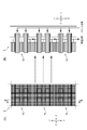
- FIG. 1 is a front view of a part of the receiver array
- B is a cross-sectional view taken along the line BB in (A).
- the heat collecting receiver of the present invention will be described.
- the heat collecting receiver of the present invention includes an absorber having a light receiving surface that absorbs sunlight, and a housing that holds the absorber and includes a first connection hole and a second connection hole.
- the absorber includes a plurality of honeycomb bodies separated from each other by a gap opened on the light receiving surface side, and a partition wall through which each honeycomb body passes, and the first connection hole includes the first connection hole,
- the second connecting hole communicates with the light receiving surface via the gap, and communicates with the light receiving surface via a honeycomb body.
- the heat collecting receiver of the present invention since it comprises an absorber that absorbs sunlight and a housing that holds the absorber, the heat absorbed by the absorber is taken into the housing and is not leaked to the outside. can do.
- the housing is provided with a first connection hole and a second connection hole, and air in opposite directions flows through the first connection hole and the second connection hole. For this reason, the air heated from one connection hole can be sucked and the used air can be returned from the other connection hole.
- the flow path extending from the first connection hole communicates with the light receiving surface via the honeycomb body, and the second connection hole communicates with the light receiving surface via the gap. For this reason, the air which received light and was heated up is attracted
- the partition wall separates the light receiving surface side, that is, the front space of the absorber, and the opposite side, that is, the rear space of the absorber.
- the absorbent body is composed only of the honeycomb bodies, and air that is not sufficiently cooled to the light receiving surface can be returned using the gaps between the honeycomb bodies. For this reason, since it is possible to configure an absorbent body made only of a honeycomb body having a function of returning air without using a special member, a heat collecting receiver can be configured without being restricted by shape, material, etc. Can do.
- the air flow is not limited to one direction, and it is also possible to return air that has not been sufficiently cooled from the honeycomb body and suck the warmed air from the gap. Accordingly, the heat collecting receiver has a function of returning air, and can sufficiently utilize the heat resistance and strength of the honeycomb body and can be stably used.
- the heat collecting receiver of the present invention has the following aspect.
- the second connection hole communicates with the light receiving surface via the side surface of the absorber and the gap.
- the air gap and the second connection hole communicate with each other via the side surface of the honeycomb body, that is, between the partition wall and the light receiving surface, rather than the partition wall. Since the front space connected to the gap is drawn to the side of the absorber, the entire side surface of the honeycomb body can be used, and air can be efficiently returned to the light receiving surface even if the gap is narrow.
- the honeycomb body is made of ceramic. Since the honeycomb body is made of ceramic, the heat collecting receiver of the present invention has heat resistance and corrosion resistance and high strength. For this reason, it can be used even in a severe environment such as a high temperature environment or a corrosive environment.
- the honeycomb body is made of one or more ceramics selected from alumina, cordierite, silicon carbide, and aluminum titanate. Since the heat collecting receiver of the present invention is made of ceramic such as alumina, cordierite, silicon carbide, aluminum titanate, etc., it is possible to provide a heat collecting receiver having high heat resistance and corrosion resistance and high strength.
- the heat collecting receiver 10 of each embodiment described below can be used for the power generation apparatus 1 using sunlight.
- the power generator 1 has a central tower 2 in the center.
- a receiver array 3 in which a plurality of heat collecting receivers 10 to be described later are accommodated is disposed at the highest position of the central tower 2.
- a steam generator 4 below the receiver array 3, a steam generator 4, a heat accumulator 5, and a steam turbine 6 are sequentially arranged.
- a number of heliostats 8 are arranged around the central tower 2.
- the heliostat 8 is set so that the reflection angle and the rotation direction around the vertical direction can be freely controlled.
- the heliostat 8 is automatically controlled so as to reflect the sunlight changing from moment to moment and collect it in the receiver array 3 of the central tower 2.
- a plurality of heat collecting receivers 10 are placed in a box with the sunlight irradiation surface open, and the light receiving surface that receives sunlight irradiation is in front. It is arranged in an aligned state.
- the heat collection receiver 10 high-temperature air heated by sunlight is sucked and the steam turbine 6 is driven, and then returned from the heat collection receiver 10 and returned to the outside.
- the heat collecting receiver 10 ⁇ / b> A of the first embodiment includes an absorber 20 ⁇ / b> A having a light receiving surface that absorbs sunlight SB reflected from the heliostat 8, and a housing that holds the absorber 20 ⁇ / b> A.
- the housing 30 ⁇ / b> A includes a housing portion 31 that houses the absorber 20 ⁇ / b> A, and pipes 33 and 34 that are continuous with the housing portion 31 and communicate with the steam generator 4 and the like.
- the absorbent body 20 ⁇ / b> A is formed by a plurality of honeycomb bodies 21 separated from each other by gaps 44.
- the absorbent body 20A houses a plurality of honeycomb bodies 21 in a housing portion 31 of a housing 30A having a square cross-sectional shape.
- a total of 25 honeycomb bodies 21 of 5 vertical ⁇ 5 horizontal are accommodated.
- the honeycomb body 21 is made of ceramic.
- the honeycomb body 21 is preferably made of, for example, one or more ceramics selected from alumina, cordierite, silicon carbide, and aluminum titanate.
- the gaps 44 between the plurality of honeycomb bodies 21 are open to the front (left side in FIG. 3) of the absorbent body 20A.
- the gap 44 is continuous with the housing part space 45 of the housing part 31 of the housing 30A.
- the accommodating space 45 is continuous with the second connection hole 27 provided between the pipe 33 and the pipe 34 provided outside the pipe 33. Therefore, the second connection hole 27 is opened to the front side of the absorbent body 20 ⁇ / b> C via the accommodating space 45 and the gap 44 on the honeycomb body 21 side of the partition wall 28.
- the outer end surface 211 of the honeycomb body 21 is a light receiving surface.
- An end portion on the inner end face 212 side of the honeycomb body 21 is supported by the partition wall 28, and the inner end face 212 is open to the rear space 26.
- the rear space 26 continues to the pipe 33 through the first connection hole 25. Therefore, the pipe 33 is open to the front of the absorbent body 20 ⁇ / b> C via the rear space 26 and the honeycomb body 21. Thereby, the air of the mutually opposite direction can distribute
- FIG. Note that the end portions on the outer end face 211 side of the honeycomb body 21 may be held at a constant interval and may not be locked to each other.
- the air illuminated by the sunlight SB from the heliostat 8 is sucked from the outer end surface 211 of the honeycomb body 21 and accommodated in the rear space 26 of the absorber 20A from the inner end surface 212.
- the air accommodated in the rear space 26 of the absorber 20A is sent to the steam generator 4 and the like through the first connection hole 25 by the pipe 33 and used for power generation.
- the air used for power generation passes through the pipe 34 and is sent from the second connection hole 27 to the accommodating portion space 45.
- the air sent to the housing space 45 is returned to the front side of the absorbent body 20 ⁇ / b> A from the gap 44 between the honeycomb bodies 21. A part of the returned air is sucked again from the outer end surface 211 of the honeycomb body 21 adjacent to the gap 44.
- the heat collecting receiver 10A of the first embodiment since the absorber 20A that absorbs sunlight and the housing 30A that holds the absorber 20A are included, the heat absorbed by the absorber 20A is taken into the housing 30A. It can be prevented from leaking outside.
- the housing 30A is provided with a first connection hole 25 and a second connection hole 27, and air in opposite directions flows through the first connection hole 25 and the second connection hole 27. ing. For this reason, the air heated from one connection hole can be sucked and the used air can be returned from the other connection hole.
- the absorbent body 20A isolates the plurality of honeycomb bodies 21 separated from each other by the gaps 44, the outer end face 211 as a light receiving surface in each honeycomb body 21, and the inner end face 212 on the opposite side to the outer end face 211. And a partition wall 28.
- the flow path extending from the first connection hole 25 communicates with the outer end surface 211 via the honeycomb body 21, and the second connection hole 27 communicates with the light receiving surface via the gap 44. For this reason, the air that has received light and has been heated is sucked from the outer end face 211, passes through the honeycomb body 21, and is sent from the inner end face 212 to the inside of the partition wall 28.
- the used air is sent from the second connection hole 27 to the gap 44 between the adjacent honeycomb bodies 21 and is returned from the light receiving surface through the gap 44.
- the partition 28 separates the light receiving surface side, that is, the front space of the absorber 20A, that is, the housing space 45, and the opposite side, that is, the rear space 26 of the absorber 20A. Since the separated air is separated by the partition wall 28, the returned air that is not sufficiently cooled is sufficiently reheated via the light receiving surface of the absorber 20A and then sucked to the generator side. For this reason, the air can be sufficiently warmed, and the thermal efficiency can be increased.
- the absorbent body 20A is composed only of the honeycomb bodies 21 and can return air that has not been sufficiently cooled to the light receiving surface using the gaps 44 between the honeycomb bodies 21. For this reason, since it is possible to configure the absorbent body 20A composed only of the honeycomb body 21 having a function of returning air without using a special member, the heat collecting receiver 10A can be configured without being restricted by shape, material, and the like. Can be configured. Note that the air flow is not limited to one direction, and it is also possible to return air that has not been sufficiently cooled from the honeycomb body 21 and suck the warmed air from the gap 44. Accordingly, the heat collecting receiver 10A has a function of returning air, and can sufficiently utilize the heat resistance and strength of the honeycomb body 21 and can be stably used.
- the air gap 44 and the second connection hole 27 communicate with each other via the side surface of the honeycomb body 21, that is, between the partition wall 28 and the light receiving surface, rather than the partition wall 28. Since the accommodating space 45 connected to the gap 44 is pulled out to the side of the absorbent body 20A, the entire side surface of the honeycomb body 21 can be used, and even if the gap 44 is narrow, the air is efficiently returned to the light receiving surface. be able to.
- the honeycomb body 21 is made of ceramic, it has heat resistance and corrosion resistance, and has high strength. For this reason, it can be used even in a severe environment such as a high temperature environment or a corrosive environment.
- the heat collecting receiver 10A of the first embodiment is made of ceramic such as alumina, cordierite, silicon carbide, aluminum titanate, etc., it is possible to provide a heat collecting receiver 10A having heat resistance and corrosion resistance and having high strength.
- the heat collecting receiver of 2nd Embodiment is demonstrated, using a figure.
- symbol is attached
- the pipe 35 is provided inside the housing 30 ⁇ / b> B housing the absorber 20 ⁇ / b> B and inside the pipe 33.
- the pipe 35 sends the used air.
- the tip of the pipe 35 passes through the partition wall 28 and continues to the gap 44 between the honeycomb bodies 21.
- the air illuminated by the sunlight SB from the heliostat 8 is sucked from the outer end surface 211 of the honeycomb body 21 and accommodated in the second rear space 26 from the inner end surface 212.
- the air accommodated in the second rear space 26 is sent to the steam generator 4 or the like by the pipe 33 through the first connection hole 25 and used for power generation.
- the air used for power generation passes through the pipe 35, is sent from the second connection hole 27 to the gap 44 between the honeycomb bodies 21, and is returned forward from the light receiving surface. A part of the returned air is sucked again from the outer end surface 211 of the honeycomb body 21 adjacent to the gap 44.
- the heat collecting receiver of 3rd Embodiment is demonstrated using a figure.
- symbol is attached
- the pipe 32 communicating with the first connection hole 25 is provided in the housing portion 31 of the housing 30 ⁇ / b> C that houses the absorber 20 ⁇ / b> C.
- the air illuminated by the sunlight SB from the heliostat 8 is sucked from the outer end surface 211 of the honeycomb body 21 and accommodated in the rear space 26 from the inner end surface 212.
- the air accommodated in the rear space 26 is sent to the steam generator 4 or the like by the pipe 33 through the second connection hole 27 and used for power generation.
- the air used for power generation passes through the pipe 32, is sent from the first connection hole 25 to the gap 44 between the honeycomb bodies 21, and is returned forward from the light receiving surface. A part of the returned air is sucked again from the outer end surface 211 of the honeycomb body 21 adjacent to the gap 44.
- the heat collecting receiver of 4th Embodiment is demonstrated, using a figure.
- symbol is attached
- the heat collection receiver 10D of the fourth embodiment includes an absorber 20D.
- the absorber 20D is accommodated in the housing 30A used in the first embodiment described above.
- the absorbent body 20D includes a plurality of honeycomb bodies 21 (22, 23) having a square cross-sectional shape.
- the honeycomb body 23 communicates with the second connection holes 27 without penetrating the partition walls 28. Therefore, the honeycomb body 22 communicates with the first connection hole 25, and the honeycomb body 22 communicates with the second connection hole 27.
- the honeycomb body 22 is the majority among the honeycomb bodies 21 (22, 23). Since the gaps 44 between the honeycomb bodies 21 (22, 23) communicate with the second connection holes 27, it is preferable that the honeycomb bodies 22 communicated with the first connection holes 25 be larger than the honeycomb bodies 23.
- the honeycomb body 22 that penetrates the partition walls 28 and the honeycomb body 23 that does not penetrate the partition walls 28 are formed of ceramics made of the same material. As shown in FIG. 7, the first connection hole 25 communicates with the light receiving surface via the honeycomb body 22 penetrating the partition wall 28, and the second connection hole 27 is a honeycomb that does not penetrate the void 44 and the partition wall 28. It communicates with the light receiving surface via the body 23.
- the air illuminated by the sunlight SB from the heliostat 8 is sucked from the outer end surface 221 of the honeycomb body 22 that penetrates the partition walls 28, passes through the partition walls 28, and is absorbed from the inner end surface 222. It is accommodated in the rear space 26 of 20D.
- the air accommodated in the rear space 26 of the absorber 20D is sent to the steam generator 4 and the like through the first connection hole 25 by the pipe 33 and used for power generation.
- the air used for power generation passes through the pipe 34 and is sent from the second connection hole 27 to the accommodating portion space 45.
- the air sent to the accommodating space 45 passes through the side surface of the honeycomb body 22, passes through the honeycomb body 23 that does not pass through the partition walls 28 from the inner end face 232 of the honeycomb body 23 that does not pass through the partition walls 28, and from the outer end face 231. Returned to the outside. At this time, air can be directly returned from the gap 44 between the honeycomb bodies 22 and 23 without penetrating the honeycomb body 23 that does not penetrate the partition walls 28. A part of the returned air is sucked again from the outer end surface 221 of the honeycomb body 22 that penetrates the partition walls 28.
- the heat collecting receiver of the present invention is not limited to the above-described embodiments, and appropriate modifications and improvements can be made.
- This application is based on a Japanese patent application filed on June 30, 2014 (Japanese Patent Application No. 2014-134584), the contents of which are incorporated herein by reference.
- the heat collecting receiver of the present invention can be used for a generator that generates power by receiving sunlight and converting it into heat.
Landscapes
- Engineering & Computer Science (AREA)
- Chemical & Material Sciences (AREA)
- Thermal Sciences (AREA)
- Life Sciences & Earth Sciences (AREA)
- Sustainable Development (AREA)
- Sustainable Energy (AREA)
- Physics & Mathematics (AREA)
- Combustion & Propulsion (AREA)
- Mechanical Engineering (AREA)
- General Engineering & Computer Science (AREA)
- Dispersion Chemistry (AREA)
- Ceramic Engineering (AREA)
- Laminated Bodies (AREA)
Abstract
集熱レシーバ(10A)は、吸収体(20A)と、吸収体(20A)を保持するハウジング(30A)とを有する。ハウジング(30A)には、第1の接続孔(25)および第2の接続孔(27)が設けられており、第1の接続孔(25)および第2の接続孔(27)は、互いに逆方向の空気が流通するようになっている。吸収体(20A)は、互いに空隙(44)により隔てられた複数のハニカム体(21)と、各ハニカム体(21)における受光面(211)と、受光面(211)とは反対側の内側端面(212)とを隔離する隔壁(28)とを有する。第1の接続孔(25)から延びる流路(33)は、ハニカム体(21)を経由して受光面(211)と連通し、第2の接続孔(27)は、空隙(44)を経由して受光面(211)と連通する。
Description
本発明は、太陽光を受けて熱に変換する集熱レシーバに関する。
太陽熱、地熱などを利用した自然エネルギーは、天然資源を枯渇させることがない上に、大気汚染、地球温暖化、廃棄物等の問題がなく、核燃料、化石燃料に替わるエネルギー源として期待されている。中でも太陽光を利用した太陽熱発電は、エネルギーの量が豊富であり、地熱エネルギーのように偏在せず、どこでも得られるのでその利用が期待されている。
太陽熱発電には、太陽の追尾機能を有するミラーを用い太陽光をタワーに備えられた集熱レシーバに集光させるタワー型の太陽熱発電がある。タワー型の太陽熱発電では、多くのミラーからの光を1カ所に集めるので高い温度が得られ、エネルギー効率が高い特徴がある。
太陽熱発電には、太陽の追尾機能を有するミラーを用い太陽光をタワーに備えられた集熱レシーバに集光させるタワー型の太陽熱発電がある。タワー型の太陽熱発電では、多くのミラーからの光を1カ所に集めるので高い温度が得られ、エネルギー効率が高い特徴がある。
タワー型の太陽熱発電に用いられる集熱レシーバは、高い温度を得るために、材質、構造など様々な工夫がされている。
特許文献1には、集熱レシーバを通過して温度上昇した空気を熱交換し、温度の低くなった空気を一部又は全部を、分岐管を用いて集熱レシーバの前面に返送し、再度吸引させるようにした集熱レシーバの構造が提案されている。
特許文献1には、集熱レシーバを通過して温度上昇した空気を熱交換し、温度の低くなった空気を一部又は全部を、分岐管を用いて集熱レシーバの前面に返送し、再度吸引させるようにした集熱レシーバの構造が提案されている。
特許文献1に記載の集熱レシーバは、吸収体の中に分岐管から集熱レシーバの受光部表面まで温度の低くなった空気の返送に用いられるパイプが備えられている。しかしながら、温度の低くなった空気を吸収体(absorber)の前面まで返送するパイプは、長い区間の空気の輸送に用い、受光部表面まで到達するため耐熱性と強度とを同時に備える必要がある。この様な形状の制約から、空気の返送に用いるパイプは、高強度でかつ耐熱性を備えた材質を用いる必要がある。
しかしながら、強度を維持するためには緻密で肉厚の素材が望ましいが、一方熱衝撃を緩和するには薄肉で多孔質の素材が好ましい。さらに、耐熱性の高い素材が必ずしも強度が高い素材ではなく、どのような空気の返送のためのパイプを備えるかが、集熱レシーバを設計する上で重要となる。すなわち、空気を返送するパイプを備えることにより、集熱レシーバの耐熱性、強度を低下させる原因となってしまう。
しかしながら、強度を維持するためには緻密で肉厚の素材が望ましいが、一方熱衝撃を緩和するには薄肉で多孔質の素材が好ましい。さらに、耐熱性の高い素材が必ずしも強度が高い素材ではなく、どのような空気の返送のためのパイプを備えるかが、集熱レシーバを設計する上で重要となる。すなわち、空気を返送するパイプを備えることにより、集熱レシーバの耐熱性、強度を低下させる原因となってしまう。
本発明では、前記課題を鑑み、空気を返送する機能を有するとともに、ハニカム体の持つ耐熱性、強度を充分に発揮でき安定して利用可能な集熱レシーバを提供することを目的とする。
前記課題を解決するための本発明の集熱レシーバは、太陽光を吸収する受光面を有する吸収体と、前記吸収体を保持するとともに、第1の接続孔および第2の接続孔を備えたハウジングと、からなる集熱レシーバであって、前記吸収体は、前記受光面側が開放する空隙により互いに隔てられた複数のハニカム体と、前記各ハニカム体が貫通する隔壁とを有し、前記第1の接続孔は、前記ハニカム体を経由して前記受光面と連通し、前記第2の接続孔は、前記空隙を経由して前記受光面と連通する。
本発明の集熱レシーバによれば、太陽光を吸収する吸収体と、吸収体を保持するハウジングとからなるので、吸収体により吸収された熱を、ハウジング内に取り込んで外部に漏らさないようにすることができる。
ハウジングには、第1の接続孔および第2の接続孔が設けられており、第1の接続孔および第2の接続孔は、互いに逆方向の空気が流通するようになっている。このため、一方の接続孔から昇温された空気を吸引して、他方の接続孔から使用後の空気を返送することができる。
ハウジングには、第1の接続孔および第2の接続孔が設けられており、第1の接続孔および第2の接続孔は、互いに逆方向の空気が流通するようになっている。このため、一方の接続孔から昇温された空気を吸引して、他方の接続孔から使用後の空気を返送することができる。
また、吸収体は、第1の接続孔から延びる流路は、ハニカム体を経由して受光面と連通し、第2の接続孔は、空隙を経由して受光面と連通する。
このため、受光して昇温した空気は外側から吸引され、ハニカム体を通って隔壁より奧に送られる。また、使用後の空気は第2の接続孔から隣接するハニカム体の間の空隙に送られ、空隙を通って返送される。隔壁は、受光面側の前方空間と、反対側の後方空間とを隔てる。隔壁により隔てられるので、充分に冷え切っていない返送された空気は吸収体の受光面を経由して充分に再加熱されてから発電機側へ吸引される。このため空気は充分に暖められることができ、熱効率を高めることができる。
また、吸収体は、ハニカム体のみからなり、ハニカム体間の空隙を利用して受光面に充分に冷え切っていない空気を返送することができる。このため、特別の部材を利用することなく空気を返送する機能を有するハニカム体のみからなる吸収体を構成することができるので、形状、材質などの制約を受けることなく集熱レシーバを構成することができる。
なお、空気の流れは一方向に限定されず、逆にハニカム体から充分に冷え切っていない空気を返送し、空隙から暖められた空気を吸引することも可能である。
これにより、集熱レシーバは、空気を返送する機能を有するとともに、ハニカム体の持つ耐熱性、強度を充分に発揮でき安定して利用することができる。
このため、受光して昇温した空気は外側から吸引され、ハニカム体を通って隔壁より奧に送られる。また、使用後の空気は第2の接続孔から隣接するハニカム体の間の空隙に送られ、空隙を通って返送される。隔壁は、受光面側の前方空間と、反対側の後方空間とを隔てる。隔壁により隔てられるので、充分に冷え切っていない返送された空気は吸収体の受光面を経由して充分に再加熱されてから発電機側へ吸引される。このため空気は充分に暖められることができ、熱効率を高めることができる。
また、吸収体は、ハニカム体のみからなり、ハニカム体間の空隙を利用して受光面に充分に冷え切っていない空気を返送することができる。このため、特別の部材を利用することなく空気を返送する機能を有するハニカム体のみからなる吸収体を構成することができるので、形状、材質などの制約を受けることなく集熱レシーバを構成することができる。
なお、空気の流れは一方向に限定されず、逆にハニカム体から充分に冷え切っていない空気を返送し、空隙から暖められた空気を吸引することも可能である。
これにより、集熱レシーバは、空気を返送する機能を有するとともに、ハニカム体の持つ耐熱性、強度を充分に発揮でき安定して利用することができる。
さらに、本発明の集熱レシーバは、以下の態様であることが望ましい。
(1)前記第2の接続孔は、前記吸収体の側面および、前記空隙を経由して前記受光面と連通する。
本発明の集熱レシーバは、空隙と第2の接続孔とが、隔壁よりもハニカム体の側面すなわち隔壁と受光面との間の中間部を経由して連通している。空隙につながる前方空間が、吸収体の側方に引き出されるので、ハニカム体の側面の全面を利用することができ、空隙が狭くても効率良く受光面へ空気を返送することができる。
(1)前記第2の接続孔は、前記吸収体の側面および、前記空隙を経由して前記受光面と連通する。
本発明の集熱レシーバは、空隙と第2の接続孔とが、隔壁よりもハニカム体の側面すなわち隔壁と受光面との間の中間部を経由して連通している。空隙につながる前方空間が、吸収体の側方に引き出されるので、ハニカム体の側面の全面を利用することができ、空隙が狭くても効率良く受光面へ空気を返送することができる。
(2)前記ハニカム体は、セラミックよりなる。
本発明の集熱レシーバは、ハニカム体がセラミックからなるので、耐熱性、耐蝕性を備え、高強度である。このため、高温環境下あるいは腐食性環境下など過酷な環境下でも使用することができる。
本発明の集熱レシーバは、ハニカム体がセラミックからなるので、耐熱性、耐蝕性を備え、高強度である。このため、高温環境下あるいは腐食性環境下など過酷な環境下でも使用することができる。
(3)前記ハニカム体は、アルミナ、コージェライト、炭化硅素、チタン酸アルミニウムより選択される1または2以上のセラミックよりなる。
本発明の集熱レシーバは、アルミナ、コージェライト、炭化珪素、チタン酸アルミニウム等のセラミックからなるので、耐熱性、耐食性を備え、高強度な集熱レシーバを提供することができる。
本発明の集熱レシーバは、アルミナ、コージェライト、炭化珪素、チタン酸アルミニウム等のセラミックからなるので、耐熱性、耐食性を備え、高強度な集熱レシーバを提供することができる。
本発明によれば、集熱レシーバを構成する吸収体は、受光面側が開放する空隙により互いに隔てられた複数のハニカム体と、前記各ハニカム体が貫通する隔壁とを有する。
そして、第1の接続孔から延びる流路は、ハニカム体を経由して受光面と連通し、第2の接続孔は、前記空隙を経由して前記受光面と連通する。これにより、集熱レシーバは、空気を返送する機能を有するとともに、ハニカム体の持つ耐熱性、強度を充分に発揮でき安定して利用することができる。
そして、第1の接続孔から延びる流路は、ハニカム体を経由して受光面と連通し、第2の接続孔は、前記空隙を経由して前記受光面と連通する。これにより、集熱レシーバは、空気を返送する機能を有するとともに、ハニカム体の持つ耐熱性、強度を充分に発揮でき安定して利用することができる。
本発明の集熱レシーバについて説明する。
本発明の集熱レシーバは、太陽光を吸収する受光面を有する吸収体と、前記吸収体を保持するとともに、第1の接続孔および第2の接続孔を備えたハウジングと、からなる集熱レシーバであって、前記吸収体は、前記受光面側が開放する空隙により互いに隔てられた複数のハニカム体と、前記各ハニカム体が貫通する隔壁とを有し、前記第1の接続孔は、前記ハニカム体を経由して前記受光面と連通し、前記第2の接続孔は、前記空隙を経由して前記受光面と連通する。
本発明の集熱レシーバによれば、太陽光を吸収する吸収体と、吸収体を保持するハウジングとからなるので、吸収体により吸収された熱を、ハウジング内に取り込んで外部に漏らさないようにすることができる。
ハウジングには、第1の接続孔および第2の接続孔が設けられており、第1の接続孔および第2の接続孔は、互いに逆方向の空気が流通するようになっている。このため、一方の接続孔から昇温された空気を吸引して、他方の接続孔から使用後の空気を返送することができる。
ハウジングには、第1の接続孔および第2の接続孔が設けられており、第1の接続孔および第2の接続孔は、互いに逆方向の空気が流通するようになっている。このため、一方の接続孔から昇温された空気を吸引して、他方の接続孔から使用後の空気を返送することができる。
また、吸収体は、第1の接続孔から延びる流路は、ハニカム体を経由して受光面と連通し、第2の接続孔は、空隙を経由して受光面と連通する。
このため、受光して昇温した空気は外側から吸引され、ハニカム体を通って隔壁の内側に送られる。また、使用後の空気は第2の接続孔から隣接するハニカム体の間の空隙に送られ、空隙を通って返送される。隔壁は、受光面側すなわち吸収体の前方空間と、反対側すなわち吸収体の後方空間とを隔てる。隔壁により隔てられるので、充分に冷え切っていない返送された空気は吸収体の受光面を経由して充分に再加熱されてから発電機側へ吸引される。このため空気は充分に暖められることができ、熱効率を高めることができる。
また、吸収体は、ハニカム体のみからなり、ハニカム体間の空隙を利用して受光面に充分に冷え切っていない空気を返送することができる。このため、特別の部材を利用することなく空気を返送する機能を有するハニカム体のみからなる吸収体を構成することができるので、形状、材質などの制約を受けることなく集熱レシーバを構成することができる。
なお、空気の流れは一方向に限定されず、逆にハニカム体から充分に冷え切っていない空気を返送し、空隙から暖められた空気を吸引することも可能である。
これにより、集熱レシーバは、空気を返送する機能を有するとともに、ハニカム体の持つ耐熱性、強度を充分に発揮でき安定して利用することができる。
このため、受光して昇温した空気は外側から吸引され、ハニカム体を通って隔壁の内側に送られる。また、使用後の空気は第2の接続孔から隣接するハニカム体の間の空隙に送られ、空隙を通って返送される。隔壁は、受光面側すなわち吸収体の前方空間と、反対側すなわち吸収体の後方空間とを隔てる。隔壁により隔てられるので、充分に冷え切っていない返送された空気は吸収体の受光面を経由して充分に再加熱されてから発電機側へ吸引される。このため空気は充分に暖められることができ、熱効率を高めることができる。
また、吸収体は、ハニカム体のみからなり、ハニカム体間の空隙を利用して受光面に充分に冷え切っていない空気を返送することができる。このため、特別の部材を利用することなく空気を返送する機能を有するハニカム体のみからなる吸収体を構成することができるので、形状、材質などの制約を受けることなく集熱レシーバを構成することができる。
なお、空気の流れは一方向に限定されず、逆にハニカム体から充分に冷え切っていない空気を返送し、空隙から暖められた空気を吸引することも可能である。
これにより、集熱レシーバは、空気を返送する機能を有するとともに、ハニカム体の持つ耐熱性、強度を充分に発揮でき安定して利用することができる。
さらに、本発明の集熱レシーバは、以下の態様であることが望ましい。
(1)前記第2の接続孔は、前記吸収体の側面および、前記空隙を経由して前記受光面と連通する。
本発明の集熱レシーバは、空隙と第2の接続孔とが、隔壁よりもハニカム体の側面すなわち隔壁と受光面との間を経由して連通している。空隙につながる前方空間が、吸収体の側方に引き出されるので、ハニカム体の側面の全面を利用することができ、空隙が狭くても効率良く受光面へ空気を返送することができる。
(1)前記第2の接続孔は、前記吸収体の側面および、前記空隙を経由して前記受光面と連通する。
本発明の集熱レシーバは、空隙と第2の接続孔とが、隔壁よりもハニカム体の側面すなわち隔壁と受光面との間を経由して連通している。空隙につながる前方空間が、吸収体の側方に引き出されるので、ハニカム体の側面の全面を利用することができ、空隙が狭くても効率良く受光面へ空気を返送することができる。
(2)前記ハニカム体は、セラミックよりなる。
本発明の集熱レシーバは、ハニカム体がセラミックからなるので、耐熱性、耐蝕性を備え、高強度である。このため、高温環境下あるいは腐食性環境下など過酷な環境下でも使用することができる。
本発明の集熱レシーバは、ハニカム体がセラミックからなるので、耐熱性、耐蝕性を備え、高強度である。このため、高温環境下あるいは腐食性環境下など過酷な環境下でも使用することができる。
(3)前記ハニカム体は、アルミナ、コージェライト、炭化硅素、チタン酸アルミニウムより選択される1または2以上のセラミックよりなる。
本発明の集熱レシーバは、アルミナ、コージェライト、炭化珪素、チタン酸アルミニウム等のセラミックからなるので、耐熱性、耐食性を備え、高強度な集熱レシーバを提供することができる。
本発明の集熱レシーバは、アルミナ、コージェライト、炭化珪素、チタン酸アルミニウム等のセラミックからなるので、耐熱性、耐食性を備え、高強度な集熱レシーバを提供することができる。
図1、図2(A)、図2(B)に示すように、以下に説明する各実施形態の集熱レシーバ10は、太陽光を用いた発電装置1に用いることができる。発電装置1は、中央に中央タワー2を有しする。中央タワー2の最も高い位置には、後述する集熱レシーバ10が複数個収容されたレシーバアレイ3が配設されている。レシーバアレイ3の下には、順次、蒸気発生器4、蓄熱器5および蒸気タービン6が配設されている。
また、中央タワー2の周囲には、多数のヘリオスタット8が配置されている。ヘリオスタット8は、反射角度や鉛直方向を軸とした回転方向を自由に制御することが可能なように設定されている。ヘリオスタット8は、時事刻々と変化する太陽光を反射して、中央タワー2のレシーバアレイ3に集めるように自動的に制御されている。
また、中央タワー2の周囲には、多数のヘリオスタット8が配置されている。ヘリオスタット8は、反射角度や鉛直方向を軸とした回転方向を自由に制御することが可能なように設定されている。ヘリオスタット8は、時事刻々と変化する太陽光を反射して、中央タワー2のレシーバアレイ3に集めるように自動的に制御されている。
図2(A)および図2(B)に示すように、レシーバアレイ3では、太陽光照射面が開放された箱に複数の集熱レシーバ10が、太陽光の照射を受ける受光面を正面に向けて整列した状態で配置されている。
集熱レシーバ10では、太陽光により昇温した高温の空気を吸引し、蒸気タービン6を駆動した後、集熱レシーバ10から戻され外部に返送される。
集熱レシーバ10では、太陽光により昇温した高温の空気を吸引し、蒸気タービン6を駆動した後、集熱レシーバ10から戻され外部に返送される。
(第1実施形態)
次に、第1実施形態の集熱レシーバについて、図を用いながら説明する。
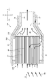
図3および図4に示すように、第1実施形態の集熱レシーバ10Aは、ヘリオスタット8から反射してきた太陽光SBを吸収する受光面を有する吸収体20Aと、吸収体20Aを保持するハウジング30Aを有する。
ハウジング30Aは、吸収体20Aを収容する収容部31と、収容部31に連続して蒸気発生器4等に連通するパイプ33、34を有する。
次に、第1実施形態の集熱レシーバについて、図を用いながら説明する。
図3および図4に示すように、第1実施形態の集熱レシーバ10Aは、ヘリオスタット8から反射してきた太陽光SBを吸収する受光面を有する吸収体20Aと、吸収体20Aを保持するハウジング30Aを有する。
ハウジング30Aは、吸収体20Aを収容する収容部31と、収容部31に連続して蒸気発生器4等に連通するパイプ33、34を有する。
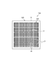
ハウジング30Aの収容部31には、吸収体20Aが、互いに空隙44により隔てた複数のハニカム体21により形成されている。吸収体20Aは、例えば、正方形の断面形状を有するハウジング30Aの収容部31に、複数個のハニカム体21を収容している。ここでは、例えば、縦5個×横5個の合計25個のハニカム体21が収容されている。
ハニカム体21は、セラミックで形成されている。ハニカム体21は、例えば、アルミナ、コージェライト、炭化硅素、チタン酸アルミニウムより選択される1または2以上のセラミックより形成されているのが望ましい。
ハニカム体21は、セラミックで形成されている。ハニカム体21は、例えば、アルミナ、コージェライト、炭化硅素、チタン酸アルミニウムより選択される1または2以上のセラミックより形成されているのが望ましい。
複数のハニカム体21の間の空隙44は、吸収体20Aの前方(図3において左方)に開放している。空隙44は、ハウジング30Aの収容部31の収容部空間45に連続している。収容部空間45は、パイプ33とパイプ33の外側に設けられているパイプ34との間に設けられている第2の接続孔27に連続している。
従って、第2の接続孔27は、隔壁28よりもハニカム体21の側にある収容部空間45および空隙44を介して、吸収体20Cの前方に開放している。
従って、第2の接続孔27は、隔壁28よりもハニカム体21の側にある収容部空間45および空隙44を介して、吸収体20Cの前方に開放している。
ハニカム体21の外側端面211は、受光面となっている。ハニカム体21の内側端面212側端部は、隔壁28で支持されており、内側端面212は後方空間26に開放している。後方空間26は、第1の接続孔25を介してパイプ33に連続している。従って、パイプ33は、後方空間26およびハニカム体21を介して、吸収体20Cの前方に開放している。
これにより、第1の接続孔25および第2の接続孔27は、互いに逆方向の空気が流通することができる。
なお、ハニカム体21の外側端面211側端部は、一定の間隔を保持していればよく、互いに係止されていなくても良い。
これにより、第1の接続孔25および第2の接続孔27は、互いに逆方向の空気が流通することができる。
なお、ハニカム体21の外側端面211側端部は、一定の間隔を保持していればよく、互いに係止されていなくても良い。
次に、集熱レシーバ10Aにおける空気の流れについて説明する。
図3に示すように、ヘリオスタット8からの太陽光SBに照らされた空気は、ハニカム体21の外側端面211から吸引され、内側端面212から吸収体20Aの後方空間26に収容される。吸収体20Aの後方空間26に収容された空気は、第1の接続孔25を介してパイプ33により蒸気発生器4等に送られて、発電に用いられる。
発電に使用された空気は、パイプ34を通り、第2の接続孔27から収容部空間45に送られる。収容部空間45に送られた空気は、ハニカム体21の間の空隙44から吸収体20Aの前方に返送される。なお、返送された空気の一部は、空隙44に隣接するハニカム体21の外側端面211から再度吸引される。
図3に示すように、ヘリオスタット8からの太陽光SBに照らされた空気は、ハニカム体21の外側端面211から吸引され、内側端面212から吸収体20Aの後方空間26に収容される。吸収体20Aの後方空間26に収容された空気は、第1の接続孔25を介してパイプ33により蒸気発生器4等に送られて、発電に用いられる。
発電に使用された空気は、パイプ34を通り、第2の接続孔27から収容部空間45に送られる。収容部空間45に送られた空気は、ハニカム体21の間の空隙44から吸収体20Aの前方に返送される。なお、返送された空気の一部は、空隙44に隣接するハニカム体21の外側端面211から再度吸引される。
次に、第1実施形態の集熱レシーバ10Aの作用、効果について説明する。
本発明の集熱レシーバ10Aによれば、太陽光を吸収する吸収体20Aと、吸収体20Aを保持するハウジング30Aとからなるので、吸収体20Aにより吸収された熱を、ハウジング30A内に取り込んで外部に漏らさないようにすることができる。
ハウジング30Aには、第1の接続孔25および第2の接続孔27が設けられており、第1の接続孔25および第2の接続孔27は、互いに逆方向の空気が流通するようになっている。このため、一方の接続孔から昇温された空気を吸引して、他方の接続孔から使用後の空気を返送することができる。
本発明の集熱レシーバ10Aによれば、太陽光を吸収する吸収体20Aと、吸収体20Aを保持するハウジング30Aとからなるので、吸収体20Aにより吸収された熱を、ハウジング30A内に取り込んで外部に漏らさないようにすることができる。
ハウジング30Aには、第1の接続孔25および第2の接続孔27が設けられており、第1の接続孔25および第2の接続孔27は、互いに逆方向の空気が流通するようになっている。このため、一方の接続孔から昇温された空気を吸引して、他方の接続孔から使用後の空気を返送することができる。
また、吸収体20Aは、互いに空隙44により隔てられた複数のハニカム体21と、各ハニカム体21における受光面としての外側端面211と、外側端面211とは反対側の内側端面212とを隔離する隔壁28とを有する。そして、第1の接続孔25から延びる流路は、ハニカム体21を経由して外側端面211と連通し、第2の接続孔27は、空隙44を経由して受光面と連通する。
このため、受光して昇温した空気は外側端面211から吸引され、ハニカム体21を通って内側端面212から隔壁28の内側に送られる。また、使用後の空気は第2の接続孔27から隣接するハニカム体21の間の空隙44に送られ、空隙44を通って受光面から返送される。隔壁28は、受光面側すなわち吸収体20Aの前方空間、すなわち収容部空間45と、反対側すなわち吸収体20Aの後方空間26とを隔てる。隔壁28により隔てられるので、充分に冷え切っていない返送された空気は吸収体20Aの受光面を経由して充分に再加熱されてから発電機側へ吸引される。このため空気は充分に暖められることができ、熱効率を高めることができる。
また、吸収体20Aは、ハニカム体21のみからなり、ハニカム体21間の空隙44を利用して受光面に充分に冷え切っていない空気を返送することができる。このため、特別の部材を利用することなく空気を返送する機能を有するハニカム体21のみからなる吸収体20Aを構成することができるので、形状、材質などの制約を受けることなく集熱レシーバ10Aを構成することができる。
なお、空気の流れは一方向に限定されず、逆にハニカム体21から充分に冷え切っていない空気を返送し、空隙44から暖められた空気を吸引することも可能である。
これにより、集熱レシーバ10Aは、空気を返送する機能を有するとともに、ハニカム体21の持つ耐熱性、強度を充分に発揮でき安定して利用することができる。
このため、受光して昇温した空気は外側端面211から吸引され、ハニカム体21を通って内側端面212から隔壁28の内側に送られる。また、使用後の空気は第2の接続孔27から隣接するハニカム体21の間の空隙44に送られ、空隙44を通って受光面から返送される。隔壁28は、受光面側すなわち吸収体20Aの前方空間、すなわち収容部空間45と、反対側すなわち吸収体20Aの後方空間26とを隔てる。隔壁28により隔てられるので、充分に冷え切っていない返送された空気は吸収体20Aの受光面を経由して充分に再加熱されてから発電機側へ吸引される。このため空気は充分に暖められることができ、熱効率を高めることができる。
また、吸収体20Aは、ハニカム体21のみからなり、ハニカム体21間の空隙44を利用して受光面に充分に冷え切っていない空気を返送することができる。このため、特別の部材を利用することなく空気を返送する機能を有するハニカム体21のみからなる吸収体20Aを構成することができるので、形状、材質などの制約を受けることなく集熱レシーバ10Aを構成することができる。
なお、空気の流れは一方向に限定されず、逆にハニカム体21から充分に冷え切っていない空気を返送し、空隙44から暖められた空気を吸引することも可能である。
これにより、集熱レシーバ10Aは、空気を返送する機能を有するとともに、ハニカム体21の持つ耐熱性、強度を充分に発揮でき安定して利用することができる。
第1実施形態の集熱レシーバ10Aは、空隙44と第2の接続孔27とが、隔壁28よりもハニカム体21の側面すなわち隔壁28と受光面との間を経由して連通している。空隙44につながる収容部空間45が、吸収体20Aの側方に引き出されるので、ハニカム体21の側面の全面を利用することができ、空隙44が狭くても効率良く受光面へ空気を返送することができる。
第1実施形態の集熱レシーバ10Aは、ハニカム体21がセラミックからなるので、耐熱性、耐蝕性を備え、高強度である。このため、高温環境下あるいは腐食性環境下など過酷な環境下でも使用することができる。
第1実施形態の集熱レシーバ10Aは、アルミナ、コージェライト、炭化珪素、チタン酸アルミニウム等のセラミックからなるので、耐熱性、耐食性を備え、高強度な集熱レシーバ10Aを提供することができる。
(第2実施形態)
次に、第2実施形態の集熱レシーバについて、図を用いながら説明する。
なお、前述した第1実施形態の集熱レシーバ10Aと共通する部位には同じ符号を付して、重複する説明を省略することとする。
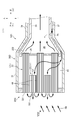
図5に示すように、第2実施形態の集熱レシーバ10Bでは、吸収体20Bを収容するハウジング30Bの内部およびパイプ33の内部に、パイプ35を設けた。パイプ35は、使用後の空気を送る。パイプ35の先端(図5において左端)は、隔壁28を貫通して、ハニカム体21の間の空隙44に連続している。
次に、第2実施形態の集熱レシーバについて、図を用いながら説明する。
なお、前述した第1実施形態の集熱レシーバ10Aと共通する部位には同じ符号を付して、重複する説明を省略することとする。
図5に示すように、第2実施形態の集熱レシーバ10Bでは、吸収体20Bを収容するハウジング30Bの内部およびパイプ33の内部に、パイプ35を設けた。パイプ35は、使用後の空気を送る。パイプ35の先端(図5において左端)は、隔壁28を貫通して、ハニカム体21の間の空隙44に連続している。
次に、集熱レシーバ10Bにおける空気の流れについて説明する。
図5に示すように、ヘリオスタット8からの太陽光SBに照らされた空気は、ハニカム体21の外側端面211から吸引され、内側端面212から第2の後方空間26に収容される。第2の後方空間26に収容された空気は、第1の接続孔25を介してパイプ33により蒸気発生器4等に送られて、発電に用いられる。
発電に使用された空気は、パイプ35を通り、第2の接続孔27からハニカム体21の間の空隙44に送られて、受光面から前方に返送される。なお、返送された空気の一部は、空隙44に隣接するハニカム体21の外側端面211から再度吸引される。
図5に示すように、ヘリオスタット8からの太陽光SBに照らされた空気は、ハニカム体21の外側端面211から吸引され、内側端面212から第2の後方空間26に収容される。第2の後方空間26に収容された空気は、第1の接続孔25を介してパイプ33により蒸気発生器4等に送られて、発電に用いられる。
発電に使用された空気は、パイプ35を通り、第2の接続孔27からハニカム体21の間の空隙44に送られて、受光面から前方に返送される。なお、返送された空気の一部は、空隙44に隣接するハニカム体21の外側端面211から再度吸引される。
このように構成しても、前述した第1実施形態の集熱レシーバ10Aと同様の作用、効果を得ることができる。
(第3実施形態)
次に、第3実施形態の集熱レシーバについて、図を用いながら説明する。
なお、前述した第1実施形態の集熱レシーバ10Aおよび第2実施形態の集熱レシーバ10Bと共通する部位には同じ符号を付して、重複する説明を省略することとする。
図6に示すように、第3実施形態の集熱レシーバ10Cでは、吸収体20Cを収容するハウジング30Cの収容部31に、第1の接続孔25に連通するパイプ32を設けた。
次に、第3実施形態の集熱レシーバについて、図を用いながら説明する。
なお、前述した第1実施形態の集熱レシーバ10Aおよび第2実施形態の集熱レシーバ10Bと共通する部位には同じ符号を付して、重複する説明を省略することとする。
図6に示すように、第3実施形態の集熱レシーバ10Cでは、吸収体20Cを収容するハウジング30Cの収容部31に、第1の接続孔25に連通するパイプ32を設けた。
次に、集熱レシーバ10Aにおける空気の流れについて説明する。
図6に示すように、ヘリオスタット8からの太陽光SBに照らされた空気は、ハニカム体21の外側端面211から吸引され、内側端面212から後方空間26に収容される。後方空間26に収容された空気は、第2の接続孔27を介してパイプ33により蒸気発生器4等に送られて、発電に用いられる。
発電に使用された空気は、パイプ32を通り、第1の接続孔25からハニカム体21の間の空隙44に送られて、受光面から前方に返送される。なお、返送された空気の一部は、空隙44に隣接するハニカム体21の外側端面211から再度吸引される。
図6に示すように、ヘリオスタット8からの太陽光SBに照らされた空気は、ハニカム体21の外側端面211から吸引され、内側端面212から後方空間26に収容される。後方空間26に収容された空気は、第2の接続孔27を介してパイプ33により蒸気発生器4等に送られて、発電に用いられる。
発電に使用された空気は、パイプ32を通り、第1の接続孔25からハニカム体21の間の空隙44に送られて、受光面から前方に返送される。なお、返送された空気の一部は、空隙44に隣接するハニカム体21の外側端面211から再度吸引される。
このように構成しても、前述した第1実施形態の集熱レシーバ10Aと同様の作用、効果を得ることができる。
(第4実施形態)
次に、第4実施形態の集熱レシーバについて、図を用いながら説明する。
なお、前述した第1実施形態の集熱レシーバ10Aないし第3実施形態の集熱レシーバ10Cと共通する部位には同じ符号を付して、重複する説明を省略することとする。
図7に示すように、第4実施形態の集熱レシーバ10Dは、吸収体20Dを有する。吸収体20Dは、前述した第1実施形態で用いられたハウジング30Aに収容されている。吸収体20Dは、正方形の断面形状の複数個のハニカム体21(22、23)よりなる。複数個のハニカム体21(22、23)のうち、ハニカム体23は隔壁28を貫通することなく第2の接続孔27と連通している。従って、ハニカム体22は、第1の接続孔25と連通し、ハニカム体22が第2の接続孔27と連通している。第4実施形態において、ハニカム体21(22、23)のうち、ハニカム体22が過半数であることが好ましい。ハニカム体21(22、23)間の空隙44は第2の接続孔27と連通しているので、第1の接続孔25と連通するハニカム体22をハニカム体23よりも多くすることが好ましい。
次に、第4実施形態の集熱レシーバについて、図を用いながら説明する。
なお、前述した第1実施形態の集熱レシーバ10Aないし第3実施形態の集熱レシーバ10Cと共通する部位には同じ符号を付して、重複する説明を省略することとする。
図7に示すように、第4実施形態の集熱レシーバ10Dは、吸収体20Dを有する。吸収体20Dは、前述した第1実施形態で用いられたハウジング30Aに収容されている。吸収体20Dは、正方形の断面形状の複数個のハニカム体21(22、23)よりなる。複数個のハニカム体21(22、23)のうち、ハニカム体23は隔壁28を貫通することなく第2の接続孔27と連通している。従って、ハニカム体22は、第1の接続孔25と連通し、ハニカム体22が第2の接続孔27と連通している。第4実施形態において、ハニカム体21(22、23)のうち、ハニカム体22が過半数であることが好ましい。ハニカム体21(22、23)間の空隙44は第2の接続孔27と連通しているので、第1の接続孔25と連通するハニカム体22をハニカム体23よりも多くすることが好ましい。
隔壁28を貫通するハニカム体22および隔壁28を貫通しないハニカム体23は、互いに同一の材質であるセラミックで形成されている。
図7に示すように、第1の接続孔25は、隔壁28を貫通するハニカム体22を経由して受光面と連通し、第2の接続孔27は、空隙44および隔壁28を貫通しないハニカム体23を経由して受光面と連通する。
図7に示すように、第1の接続孔25は、隔壁28を貫通するハニカム体22を経由して受光面と連通し、第2の接続孔27は、空隙44および隔壁28を貫通しないハニカム体23を経由して受光面と連通する。
次に、集熱レシーバ10Dにおける空気の流れについて説明する。
図7に示すように、ヘリオスタット8からの太陽光SBに照らされた空気は、隔壁28を貫通するハニカム体22の外側端面221から吸引され、隔壁28を貫通して内側端面222から吸収体20Dの後方空間26に収容される。吸収体20Dの後方空間26に収容された空気は、第1の接続孔25を介してパイプ33により蒸気発生器4等に送られて、発電に用いられる。
発電に使用された空気は、パイプ34を通り、第2の接続孔27から収容部空間45に送られる。収容部空間45に送られた空気は、ハニカム体22の側面を経由したのち、隔壁28を貫通しないハニカム体23の内側端面232から隔壁28を貫通しないハニカム体23を貫通し、外側端面231から外部に返送される。このとき、隔壁28を貫通しないハニカム体23を貫通することなくハニカム体22、23間の空隙44から直接空気を返送するようにすることもできる。なお、返送された空気の一部は、隔壁28を貫通するハニカム体22の外側端面221から再度吸引される。
図7に示すように、ヘリオスタット8からの太陽光SBに照らされた空気は、隔壁28を貫通するハニカム体22の外側端面221から吸引され、隔壁28を貫通して内側端面222から吸収体20Dの後方空間26に収容される。吸収体20Dの後方空間26に収容された空気は、第1の接続孔25を介してパイプ33により蒸気発生器4等に送られて、発電に用いられる。
発電に使用された空気は、パイプ34を通り、第2の接続孔27から収容部空間45に送られる。収容部空間45に送られた空気は、ハニカム体22の側面を経由したのち、隔壁28を貫通しないハニカム体23の内側端面232から隔壁28を貫通しないハニカム体23を貫通し、外側端面231から外部に返送される。このとき、隔壁28を貫通しないハニカム体23を貫通することなくハニカム体22、23間の空隙44から直接空気を返送するようにすることもできる。なお、返送された空気の一部は、隔壁28を貫通するハニカム体22の外側端面221から再度吸引される。
このように構成しても、前述した第1実施形態の集熱レシーバ10Aと同様の作用、効果を得ることができる。
なお、太陽光SBに照らされた空気を隔壁28を貫通しないハニカム体23および空隙44から吸引して、蒸気発生器4等に送り、使用後の空気を隔壁28を貫通するハニカム体22から返送することもできる。
なお、太陽光SBに照らされた空気を隔壁28を貫通しないハニカム体23および空隙44から吸引して、蒸気発生器4等に送り、使用後の空気を隔壁28を貫通するハニカム体22から返送することもできる。
本発明の集熱レシーバは、前述した各実施形態に限定されるものでなく、適宜な変形、改良等が可能である。
本出願は、2014年6月30日出願の日本国特許出願(特願2014-134584)に基づくものであり、それらの内容はここに参照として取り込まれる。
本出願は、2014年6月30日出願の日本国特許出願(特願2014-134584)に基づくものであり、それらの内容はここに参照として取り込まれる。
本発明の集熱レシーバは、太陽光を受けて熱に変換して発電する発電機等に用いることができる。
10A、10B、10C、10D 集熱レシーバ
20A、20B、20C、20D 吸収体
21、22、23 ハニカム体
211 外側端面(受光面)
212 内側端面
25 第1の接続孔
27 第2の接続孔
28 隔壁
30A、30B、30C、30D ハウジング
44 空隙
20A、20B、20C、20D 吸収体
21、22、23 ハニカム体
211 外側端面(受光面)
212 内側端面
25 第1の接続孔
27 第2の接続孔
28 隔壁
30A、30B、30C、30D ハウジング
44 空隙
Claims (4)
- 太陽光を吸収する受光面を有する吸収体と、
前記吸収体を保持するとともに、第1の接続孔および第2の接続孔を備えたハウジングと、からなる集熱レシーバであって、
前記吸収体は、前記受光面側が開放する空隙により互いに隔てられた複数のハニカム体と、前記各ハニカム体が貫通する隔壁とを有し、
前記第1の接続孔は、前記ハニカム体を経由して前記受光面と連通し、前記第2の接続孔は、前記空隙を経由して前記受光面と連通する集熱レシーバ。 - 請求項1に記載の集熱レシーバにおいて、
前記第2の接続孔は、前記吸収体の側面および、前記空隙を経由して前記受光面と連通することを特徴とする請求項1に集熱レシーバ。 - 請求項1または請求項2に記載の集熱レシーバにおいて、
前記ハニカム体は、セラミックよりなる集熱レシーバ。 - 請求項3に記載の集熱レシーバにおいて、
前記ハニカム体は、アルミナ、コージェライト、炭化硅素、チタン酸アルミニウムより選択される1または2以上のセラミックよりなる集熱レシーバ。
Applications Claiming Priority (2)
| Application Number | Priority Date | Filing Date | Title |
|---|---|---|---|
| JP2014134584A JP2016011810A (ja) | 2014-06-30 | 2014-06-30 | 集熱レシーバ |
| JP2014-134584 | 2014-06-30 |
Publications (1)
| Publication Number | Publication Date |
|---|---|
| WO2016002823A1 true WO2016002823A1 (ja) | 2016-01-07 |
Family
ID=55019353
Family Applications (1)
| Application Number | Title | Priority Date | Filing Date |
|---|---|---|---|
| PCT/JP2015/068924 Ceased WO2016002823A1 (ja) | 2014-06-30 | 2015-06-30 | 集熱レシーバ |
Country Status (2)
| Country | Link |
|---|---|
| JP (1) | JP2016011810A (ja) |
| WO (1) | WO2016002823A1 (ja) |
Cited By (1)
| Publication number | Priority date | Publication date | Assignee | Title |
|---|---|---|---|---|
| WO2020083972A1 (de) * | 2018-10-23 | 2020-04-30 | Kraftanlagen München Gmbh | Absorbermodul |
Citations (3)
| Publication number | Priority date | Publication date | Assignee | Title |
|---|---|---|---|---|
| WO2003021160A1 (en) * | 2001-09-06 | 2003-03-13 | Stobbe Tech Holding A/S | Hybrid volumetric receiver assembly and process for producing such assembly |
| WO2004023048A1 (en) * | 2002-09-06 | 2004-03-18 | Kraftanlagen Munchen Gmbh | Combined and simplified ceramic or metallic volumetric absorber modules |
| DE102004030433B3 (de) * | 2004-06-24 | 2005-08-11 | Deutsches Zentrum für Luft- und Raumfahrt e.V. | Solarempfänger |
-
2014
- 2014-06-30 JP JP2014134584A patent/JP2016011810A/ja active Pending
-
2015
- 2015-06-30 WO PCT/JP2015/068924 patent/WO2016002823A1/ja not_active Ceased
Patent Citations (3)
| Publication number | Priority date | Publication date | Assignee | Title |
|---|---|---|---|---|
| WO2003021160A1 (en) * | 2001-09-06 | 2003-03-13 | Stobbe Tech Holding A/S | Hybrid volumetric receiver assembly and process for producing such assembly |
| WO2004023048A1 (en) * | 2002-09-06 | 2004-03-18 | Kraftanlagen Munchen Gmbh | Combined and simplified ceramic or metallic volumetric absorber modules |
| DE102004030433B3 (de) * | 2004-06-24 | 2005-08-11 | Deutsches Zentrum für Luft- und Raumfahrt e.V. | Solarempfänger |
Cited By (1)
| Publication number | Priority date | Publication date | Assignee | Title |
|---|---|---|---|---|
| WO2020083972A1 (de) * | 2018-10-23 | 2020-04-30 | Kraftanlagen München Gmbh | Absorbermodul |
Also Published As
| Publication number | Publication date |
|---|---|
| JP2016011810A (ja) | 2016-01-21 |
Similar Documents
| Publication | Publication Date | Title |
|---|---|---|
| MX2010002514A (es) | Modulo fotovoltaico solar de concentracion de canal doble. | |
| US20100264656A1 (en) | Orbiting power plant | |
| WO2015193870A2 (en) | Dual-stage parabolic concentrator | |
| WO2013059112A1 (en) | Hybrid solar/non-solar energy generation system and method | |
| AU2020203012A1 (en) | Solar power collection systems and methods thereof | |
| JP2016532842A (ja) | 太陽エネルギー収集器およびそれを用いたシステム{solar energy collector and system for using same} | |
| CN105452655A (zh) | 用于近海应用的高效太阳能发电机 | |
| US20160233829A1 (en) | Solar water-collecting, air-conditioning, light-transmitting and power generating house | |
| WO2016002823A1 (ja) | 集熱レシーバ | |
| WO2011157799A1 (en) | Solar collector assembly with at least one clinching connection, method for manufacturing the solar collector assembly by a clinching mechanism and use of the solar collector assembly | |
| KR101293420B1 (ko) | 태양열 발전시스템 | |
| ES2950333T3 (es) | Central solar | |
| CN100429397C (zh) | 簇式储热太阳能光热发电装置 | |
| WO2016002822A1 (ja) | 集熱レシーバ | |
| US10895406B1 (en) | Solar concentrator | |
| WO2016002824A1 (ja) | 集熱レシーバ | |
| US20150179910A1 (en) | System For Converting Thermal Energy Into Electrical Energy | |
| ES2746299T3 (es) | Dispositivo colector de calor solar | |
| CN205066180U (zh) | 一种塔式电站中的光热接收装置及塔式太阳能利用装置 | |
| WO2018050075A1 (zh) | 太阳能集热器 | |
| KR101156939B1 (ko) | 태양열 발전 시스템 | |
| EP3121530A1 (en) | Torque tube of a support structure for supporting a mirror; solar collector assembly with the support structure and use of the solar collector assembly for solar field | |
| KR101104694B1 (ko) | 타워형 태양발전시스템의 작동유체 순환 구조 | |
| JP2016017690A (ja) | 集熱レシーバ | |
| US9556855B2 (en) | Double flow channel open-type solar heat absorber having porous plate arrangement |
Legal Events
| Date | Code | Title | Description |
|---|---|---|---|
| 121 | Ep: the epo has been informed by wipo that ep was designated in this application |
Ref document number: 15815079 Country of ref document: EP Kind code of ref document: A1 |
|
| NENP | Non-entry into the national phase |
Ref country code: DE |
|
| 122 | Ep: pct application non-entry in european phase |
Ref document number: 15815079 Country of ref document: EP Kind code of ref document: A1 |