WO2016002715A1 - カーボンナノチューブの表面処理方法 - Google Patents
カーボンナノチューブの表面処理方法 Download PDFInfo
- Publication number
- WO2016002715A1 WO2016002715A1 PCT/JP2015/068681 JP2015068681W WO2016002715A1 WO 2016002715 A1 WO2016002715 A1 WO 2016002715A1 JP 2015068681 W JP2015068681 W JP 2015068681W WO 2016002715 A1 WO2016002715 A1 WO 2016002715A1
- Authority
- WO
- WIPO (PCT)
- Prior art keywords
- carbon nanotube
- carbon nanotubes
- surface treatment
- heat treatment
- carbon
- Prior art date
- Legal status (The legal status is an assumption and is not a legal conclusion. Google has not performed a legal analysis and makes no representation as to the accuracy of the status listed.)
- Ceased
Links
Images




Classifications
-
- B—PERFORMING OPERATIONS; TRANSPORTING
- B82—NANOTECHNOLOGY
- B82B—NANOSTRUCTURES FORMED BY MANIPULATION OF INDIVIDUAL ATOMS, MOLECULES, OR LIMITED COLLECTIONS OF ATOMS OR MOLECULES AS DISCRETE UNITS; MANUFACTURE OR TREATMENT THEREOF
- B82B1/00—Nanostructures formed by manipulation of individual atoms or molecules, or limited collections of atoms or molecules as discrete units
-
- C—CHEMISTRY; METALLURGY
- C01—INORGANIC CHEMISTRY
- C01B—NON-METALLIC ELEMENTS; COMPOUNDS THEREOF; METALLOIDS OR COMPOUNDS THEREOF NOT COVERED BY SUBCLASS C01C
- C01B32/00—Carbon; Compounds thereof
- C01B32/05—Preparation or purification of carbon not covered by groups C01B32/15, C01B32/20, C01B32/25, C01B32/30
Definitions
- the present invention relates to a surface treatment method for carbon nanotubes, and relates to a surface treatment method for improving the strength of carbon nanotubes and the interfacial strength when a composite material is used.
- carbon nanotubes have characteristics such as high mechanical strength, lightness, good electrical conductivity, good thermal characteristics, and good field electron emission characteristics, scanning probe microscope (SPM) probes and field emission displays (FED), cold cathode, conductive resin, high-strength resin, corrosion-resistant resin, wear-resistant resin, highly lubricating resin, secondary battery and fuel cell electrodes, LSI interlayer wiring materials, biosensors, etc.
- SPM scanning probe microscope
- FED field emission displays
- cold cathode conductive resin
- high-strength resin corrosion-resistant resin
- wear-resistant resin highly lubricating resin
- secondary battery and fuel cell electrodes LSI interlayer wiring materials
- biosensors etc.
- CNTRP ultra-lightweight high-performance carbon nanotube / resin composite
- CNTRP is expected as a next-generation structural material to replace carbon fiber reinforced composite (CFRP) in all structural materials including future transportation systems.
- Patent Document 1 there is known a method of generating a large number of vertically aligned carbon nanotubes using ferrous chloride (or ferric chloride) as a catalyst. It is conceivable to produce a unidirectionally oriented carbon nanotube sheet from such a number of vertically aligned carbon nanotubes. In that case, the diameter, length, crystallinity, density, shape, etc. of the carbon nanotubes affect the spinnability for processing into a unidirectionally oriented carbon nanotube sheet, but the technology to control and improve the spinnability is unknown. In addition, there is no known technique for controlling the surface characteristics of carbon nanotubes in order to increase the interface strength.
- JP 2009-196873 A Japanese Patent Laid-Open No. 2006-21369
- Carbon nanotubes often have surface damage during the production process when synthesized by chemical vapor deposition, and carbon nanotubes produced using a catalyst, such as the method shown in Patent Document 1, Impurities are likely to be present in the surface layer. Such damage and the presence of impurities have the problem that the strength of the carbon nanotube itself cannot be obtained as well as a decrease in the interface strength. For this reason, it is known to perform surface treatment on the produced carbon nanotubes.
- a chemical process method using a strong acid is known as a surface treatment technique for carbon nanotubes.
- a highly acidic liquid is used, it is difficult to accurately control the surface treatment process.
- defects may occur in the surface layer, and the interface strength is increased to improve the strength of the composite material. It was difficult to use.
- Patent Document 2 it is known that the surface layer is cleaned by sputter etching on the surface layer of the carbon nanotube (carbon nanofiber), thereby increasing the interface strength of the carbon nanotube. Can be considered. However, the process is complicated, and equipment such as a power source and a complicated configuration for its control are also required. Moreover, when performing surface treatment of a large number of vertically aligned carbon nanotubes manufactured using iron chloride as a catalyst, as shown in Patent Document 1, a different processing apparatus is separately required and densely generated. It is extremely difficult to perform sputter etching uniformly on the surface layer of all carbon nanotubes. Furthermore, carbon nanotubes obtained by the method shown in Patent Document 1 may use iron chloride as a catalyst and have impurities in the surface layer. The method shown in Patent Document 2 sufficiently removes the impurities. Is difficult.
- the present invention is capable of accurately controlling the surface treatment process of any form of carbon nanotubes with a simple configuration, increasing the strength of the carbon nanotubes, increasing the interfacial strength, and improving the spinnability. It is an object of the present invention to provide a surface treatment method for carbon nanotubes that can be applied.
- the surface treatment method for carbon nanotubes according to the present invention solves the above problems by performing heat treatment for a predetermined time in an atmosphere in which an inert gas and hydrogen gas are mixed.
- a dry treatment using a gas in which an inert gas and a hydrogen gas are mixed by performing a heat treatment for a predetermined time in an atmosphere in which an inert gas and a hydrogen gas are mixed. It is possible to perform surface treatment in a harsh environment, facilitating equipment and handling.
- hydrogen gas is used as an activator, it is possible to treat irregularities and defects in the carbon itself of the carbon nanotubes in the surface layer, and it is possible to remove impurities other than carbon in the surface layer, such as iron chloride. It is also possible to remove impurities present in the surface layer of the carbon nanotubes produced using this catalyst.
- the surface treatment process can be easily and accurately controlled only by turning on and off the supply of hydrogen gas, and the carbon nanotube can be accurately set to desired surface characteristics. Furthermore, even in the case where a large number of carbon nanotubes are densely produced, such as a carbon nanotube array having a large number of vertically aligned carbon nanotubes, a surface treatment is applied evenly to each carbon nanotube because of the use of gas. It is possible to improve the spinnability of carbon nanotubes by post-treatment.
- the surface treatment process is accurately and finely controlled by controlling one or both of the hydrogen gas concentration and the heat treatment time at a predetermined heat treatment temperature of 600 ° C. to 800 ° C. Control becomes possible.
- the heat treatment temperature is lower than 600 ° C., the reaction between the hydrogen gas and the carbon nanotube surface layer is not sufficiently performed, and the surface treatment takes a long time.
- the heat treatment temperature exceeds 800 ° C., the reaction rate between the hydrogen gas and the carbon nanotube surface layer is high, and it becomes difficult to accurately control the surface treatment process by controlling the hydrogen gas concentration or the heat treatment time. There is a risk of damage other than the surface layer.
- the surface treatment process can be controlled more precisely and finely.
- the hydrogen gas concentration is less than 10%, the reaction between the hydrogen gas and the surface layer of the carbon nanotube is not sufficiently performed, and the surface treatment takes a long time and the crystallinity of the surface layer of the carbon nanotube is lowered.
- the hydrogen gas concentration exceeds 30%, the reaction rate between the hydrogen gas and the surface layer of the carbon nanotube is too fast, and it becomes difficult to control the surface treatment process accurately.
- the heat treatment time is 10 minutes to 60 minutes, so that the surface treatment process can be accurately and finely controlled. If the heat treatment time is less than 10 minutes, the surface layer of all the carbon nanotubes may not be uniformly reacted, and the crystallinity of the carbon nanotubes will not be improved. When the heat treatment time exceeds 60 minutes, the crystallinity of the carbon nanotubes decreases, the surface characteristics deteriorate, and the reaction proceeds from the surface layer to the back, so that the characteristics of the carbon nanotubes themselves deteriorate. According to the configuration of the present invention, the spinnability of the carbon nanotube can be improved by controlling the interface strength of the carbon nanotube by controlling one or both of the hydrogen gas concentration and the heat treatment time.
- the strength of the carbon nanotube itself can be improved by removing the surface damage of the carbon nanotube by controlling one or both of the hydrogen gas concentration and the heat treatment time.
- an ultralight, ultrahigh strength array having a simple structure is obtained by using carbon nanotubes having high strength, high interfacial strength, and improved spinnability. , Sheets and composites.
- the carbon nanotube surface treatment method of the present invention is a method in which heat treatment is performed for a predetermined time in an atmosphere in which an inert gas and hydrogen gas are mixed. As long as the treatment process can be accurately controlled and the strength of the carbon nanotubes can be increased, the interfacial strength can be increased, and the spinnability can be improved, any specific embodiment can be used. .
- a surface treatment apparatus 100 that performs surface treatment of carbon nanotubes includes an inert gas supply pipe 112, an active gas supply pipe 113, and an exhaust pipe 114.
- a reaction tube 110 on which CNT can be placed and a heater 111 for heating the inside of the reaction tube 110 are provided.
- argon as an inert gas is supplied from the inert gas supply tube 112 to make the inside of the reaction tube 110 an inert atmosphere.
- argon from the inert gas supply pipe 112 and hydrogen from the active gas supply pipe 113 are respectively supplied at a predetermined flow rate so that hydrogen as an active gas has a predetermined concentration.
- Supply Maintain the set temperature and continue supplying argon and hydrogen while controlling the hydrogen concentration.
- FIG. 2 shows scanning micrographs of cross sections of the carbon nanotube array before and after the surface treatment according to the present invention.
- the surface treatment removes surface damage and impurities from the carbon nanotubes and improves crystallization.
- FIG. 4 shows a scanning micrograph of a cross section of a carbon nanotube array obtained by performing the surface treatment of the present invention with the same heat treatment time and different hydrogen concentrations
- FIG. 5 shows a graph of the relationship between the crystallization ratios of carbon nanotubes with different hydrogen concentrations.
- the carbon nanotube arrays (FIGS. 4c and d) surface-treated with hydrogen concentrations of 10% and 25%, respectively, have improved crystallinity compared to the untreated one (FIG. 4a).
- FIG. 4a shows a scanning micrograph of a cross section of a carbon nanotube array obtained by performing the surface treatment time and different hydrogen concentrations
- FIG. 5 shows a graph of the relationship between the crystallization ratios of carbon nanotubes with different hydrogen concentrations.
- the carbon nanotube arrays (FIGS. 4c and d) surface-treated with hydrogen concentrations of 10% and 25%, respectively, have improved crystallinity compared to the untreated one (FIG. 4a).
- FIG. 4a shows a scanning micrograph
- FIG. 6 shows a scanning micrograph of a cross-section of a carbon nanotube array in which the surface treatment of the present invention was performed at a hydrogen concentration of 10% and different heat treatment times (the carbon nanotubes produced under the same conditions as those shown in FIG. 4 described above).
- Array Compared to the carbon nanotube array without surface treatment (FIG. 6a), the carbon nanotube array (FIG. 6b, c, d, e) surface-treated with a heat treatment time of 10 minutes, 20 minutes, 30 minutes, and 60 minutes, respectively, The crystallinity of the carbon nanotube is also improved. Also, as shown in each enlarged photo, the number of adjacent carbon nanotubes in bundles increased, and the surface characteristics were improved to the level at which van der Waals force works between the surfaces of adjacent carbon nanotubes. I understand.
- the surface properties, straightness, crystallinity, etc. of the carbon nanotube array surface-treated with each heat treatment time are different, and the heat treatment time can be easily and accurately controlled only by turning on and off the supply of hydrogen gas. It was found that carbon nanotubes having desired surface characteristics can be obtained. From these results, it can be seen that by controlling the heat treatment time, the surface characteristics of the carbon nanotubes can be controlled, the interface strength can be controlled, the crystallinity can be controlled, the surface damage can be removed, and the straightness can be controlled.
- FIG. 7 shows a scanning micrograph of a cross section of a carbon nanotube / resin composite material using the carbon nanotubes obtained by subjecting the surface treatment of the present invention to different heat treatment times.
- the carbon nanotubes used in the carbon nanotube / resin composite material in this embodiment are processed into a carbon nanotube sheet by drawing a large number of carbon nanotubes generated as a carbon nanotube array in one direction from the end to form a sheet shape.
- the surface treatment of the carbon nanotubes was performed in the state of a carbon nanotube array.
- the resin used for the carbon nanotube / resin composite material is an epoxy resin.
- FIG. 7a In the cross-section (FIG. 7a) of the carbon nanotube / resin composite material using the carbon nanotubes not subjected to the surface treatment, many hollow portions (white portions) from which the carbon nanotubes are detached can be seen. This indicates that the bonding strength between the carbon nanotube and the epoxy resin is small due to the low interface strength of the carbon nanotube, and the strength as the carbon nanotube / resin composite material is also low.
- the bonding strength between the carbon nanotube and the epoxy resin is increased due to the high interfacial strength of the carbon nanotube, and the strength as the carbon nanotube / resin composite material is also increased.
- the portion (shown by an arrow) whose end portion is greatly expanded in a fan shape is carbon. This shows that the bonding force between the nanotube and the epoxy resin is extremely large.
- the heat treatment can be performed for a predetermined time in an atmosphere in which an inert gas and hydrogen gas are mixed, and the surface characteristics of the carbon nanotube can be changed. It is possible to increase the interfacial strength and improve the spinnability.
- composite materials with arrays, sheets, and other materials can be applied to ultra-light, ultra-high strength composite materials for various applications. It becomes possible.
Landscapes
- Chemical & Material Sciences (AREA)
- Organic Chemistry (AREA)
- Crystallography & Structural Chemistry (AREA)
- Engineering & Computer Science (AREA)
- Nanotechnology (AREA)
- Inorganic Chemistry (AREA)
- Carbon And Carbon Compounds (AREA)
Abstract
簡単な構成で、いかなる形態のカーボンナノチューブであっても、表面処理プロセスを正確に制御可能であり、カーボンナノチューブの強度を高め、界面強度を高め、紡績性を向上することが可能なカーボンナノチューブの表面処理方法を提供すること。 カーボンナノチューブの表面処理方法であって、不活性ガスと水素ガスを混合した雰囲気中で、所定の時間熱処理を行うこと。
Description
本発明はカーボンナノチューブの表面処理方法に係り、カーボンナノチューブの強度や複合材とした際の界面強度を向上する表面処理方法に関する。
カーボンナノチューブは、機械的強度が高い、軽い、電気伝導特性が良い、熱特性が良い、電界電子放出特性が良い等の特性を有することから、走査プローブ顕微鏡(SPM)の探針、電界放出ディスプレイ(FED)、の冷陰極、導電性樹脂、高強度樹脂、耐腐食性樹脂、耐摩耗性樹脂、高度潤滑性樹脂、二次電池や燃料電池の電極、LSIの層間配線材料、バイオセンサーなど、様々な技術への応用が注目されている。
特に、超軽量性高性能カーボンナノチューブ・樹脂複合材(CNTRP)は将来の輸送システムを始めとする構造材料全てにおいて炭素繊維強化複合材(CFRP)に代わる次世代構造用材料として期待されている。
特に、超軽量性高性能カーボンナノチューブ・樹脂複合材(CNTRP)は将来の輸送システムを始めとする構造材料全てにおいて炭素繊維強化複合材(CFRP)に代わる次世代構造用材料として期待されている。
従来のカーボンナノチューブ・樹脂複合材料は粉末状のカーボンナノチューブを樹脂内に分散する方法で作られてきたが、この方法ではカーボンナノチューブの配向性が一様ではなく、炭素繊維強化複合材に匹敵するような力学特性の大幅向上はない。
カーボンナノチューブの優れた特性を生かすためには一方向配向性のカーボンナノチューブシートを製造して複合材を制作する必要がある。
しかしながら、一方向配向カーボンナノチューブシートの製造技術はまだ世界でも低い達成率を示す技術であり、カーボンナノチューブ合成条件とシート状に成形するためのカーボンナノチューブの紡績性との相関関係等はまだ明確化していない。
また、カーボンナノチューブ・樹脂複合材料を製造した際、より高い強度を実現するためには、カーボンナノチューブと樹脂との界面強度を高める必要がある。
この界面強度は、カーボンナノチューブの表面特性等が影響する。
カーボンナノチューブの優れた特性を生かすためには一方向配向性のカーボンナノチューブシートを製造して複合材を制作する必要がある。
しかしながら、一方向配向カーボンナノチューブシートの製造技術はまだ世界でも低い達成率を示す技術であり、カーボンナノチューブ合成条件とシート状に成形するためのカーボンナノチューブの紡績性との相関関係等はまだ明確化していない。
また、カーボンナノチューブ・樹脂複合材料を製造した際、より高い強度を実現するためには、カーボンナノチューブと樹脂との界面強度を高める必要がある。
この界面強度は、カーボンナノチューブの表面特性等が影響する。
特許文献1に示すように、塩化第1鉄(または塩化第2鉄)を触媒として利用して垂直配向した多数のカーボンナノチューブを生成する方法が知られている。
このような垂直配向した多数のカーボンナノチューブから一方向配向カーボンナノチューブシートの製造をすることが考えられる。
その際には、カーボンナノチューブの直径、長さ、結晶性、密度、形態等が一方向配向カーボンナノチューブシートに加工するための紡績性に影響するが、その紡績性を制御し、向上する技術は知られていない。
また、界面強度を高めるために、カーボンナノチューブの表面特性等を制御する技術は知られていない。
このような垂直配向した多数のカーボンナノチューブから一方向配向カーボンナノチューブシートの製造をすることが考えられる。
その際には、カーボンナノチューブの直径、長さ、結晶性、密度、形態等が一方向配向カーボンナノチューブシートに加工するための紡績性に影響するが、その紡績性を制御し、向上する技術は知られていない。
また、界面強度を高めるために、カーボンナノチューブの表面特性等を制御する技術は知られていない。
カーボンナノチューブは、化学気相蒸着法により合成する際に生成過程で表面損傷が存在することが多く、また、特許文献1に示す方法のように、触媒を使用して生成されるカーボンナノチューブでは、表面層に不純物が存在しやすい。
このような損傷や不純物の存在は、界面強度の低下のみならず、カーボンナノチューブ自体の強度が得られないという問題がある。
このため、生成したカーボンナノチューブに対して表面処理を行うことが知られている。
このような損傷や不純物の存在は、界面強度の低下のみならず、カーボンナノチューブ自体の強度が得られないという問題がある。
このため、生成したカーボンナノチューブに対して表面処理を行うことが知られている。
一般的に、カーボンナノチューブの表面処理技術として、強酸を用いた化学プロセス法が知られている。
しかしながら、強酸性の液体を用いることから表面処理プロセスの正確な制御が困難であり、逆に表面層にも欠陥が発生することもあり、複合材の強度向上のために界面強度を高める用途に使用することは困難であった。
しかしながら、強酸性の液体を用いることから表面処理プロセスの正確な制御が困難であり、逆に表面層にも欠陥が発生することもあり、複合材の強度向上のために界面強度を高める用途に使用することは困難であった。
また、特許文献2に示すように、カーボンナノチューブ(カーボンナノファイバー)の表面層にスパッタエッチングすることで表面層を清浄化することが知られており、これにより、カーボンナノチューブの界面強度を高めることが考えられる。
しかしながら、工程は複雑であり、電源等の設備やその制御のための複雑な構成も必要となる。
また、特許文献1に示すような、触媒として塩化鉄を使用して製造した垂直配向した多数のカーボンナノチューブの表面処理を行う場合、異なる処理装置を別途必要とする上、密に生成されている全てのカーボンナノチューブの表面層に均等にスパッタエッチングを行うことは極めて困難である。
さらに、特許文献1に示す方法で得られるカーボンナノチューブは、触媒として塩化鉄を使用し表面層に不純物が存在することがあり、特許文献2に示すような方法では、その不純物を充分に取り除くことが困難である。
しかしながら、工程は複雑であり、電源等の設備やその制御のための複雑な構成も必要となる。
また、特許文献1に示すような、触媒として塩化鉄を使用して製造した垂直配向した多数のカーボンナノチューブの表面処理を行う場合、異なる処理装置を別途必要とする上、密に生成されている全てのカーボンナノチューブの表面層に均等にスパッタエッチングを行うことは極めて困難である。
さらに、特許文献1に示す方法で得られるカーボンナノチューブは、触媒として塩化鉄を使用し表面層に不純物が存在することがあり、特許文献2に示すような方法では、その不純物を充分に取り除くことが困難である。
そこで、本発明は、簡単な構成で、いかなる形態のカーボンナノチューブであっても、表面処理プロセスを正確に制御可能であり、カーボンナノチューブの強度を高め、界面強度を高め、紡績性を向上することが可能なカーボンナノチューブの表面処理方法を提供することを目的とする。
本発明に係るカーボンナノチューブの表面処理方法は、不活性ガスと水素ガスを混合した雰囲気中で、所定の時間熱処理を行うことにより、前記課題を解決するものである。
本発明に係るカーボンナノチューブの表面処理方法によれば、不活性ガスと水素ガスを混合した雰囲気中で、所定の時間熱処理を行うことにより、不活性ガスと水素ガスを混合した気体を使用するドライな環境で表面処理を行うことが可能であり、設備やハンドリングが容易となる。
また、水素ガスを活性剤として使用するため、表面層のカーボンナノチューブの炭素自体の凹凸や欠損を処理可能であるとともに、表面層の炭素以外の不純物を除去することが可能であり、塩化鉄等の触媒を使用して生成したカーボンナノチューブの表面層に存在する不純物を取り除くことも可能となる。
さらに、水素ガスの供給のオンオフのみで表面処理プロセスを容易に正確に制御可能であり、カーボンナノチューブを正確に所望の表面特性とすることができる。
さらに、垂直配向した多数のカーボンナノチューブを有するカーボンナノチューブアレイ等の、多数のカーボンナノチューブが密に生成されている対象であっても、気体を使用するため、個々のカーボンナノチューブに均等に表面処理を行うことが可能であり、後処理でカーボンナノチューブの紡績性を向上することが可能となる。
また、水素ガスを活性剤として使用するため、表面層のカーボンナノチューブの炭素自体の凹凸や欠損を処理可能であるとともに、表面層の炭素以外の不純物を除去することが可能であり、塩化鉄等の触媒を使用して生成したカーボンナノチューブの表面層に存在する不純物を取り除くことも可能となる。
さらに、水素ガスの供給のオンオフのみで表面処理プロセスを容易に正確に制御可能であり、カーボンナノチューブを正確に所望の表面特性とすることができる。
さらに、垂直配向した多数のカーボンナノチューブを有するカーボンナノチューブアレイ等の、多数のカーボンナノチューブが密に生成されている対象であっても、気体を使用するため、個々のカーボンナノチューブに均等に表面処理を行うことが可能であり、後処理でカーボンナノチューブの紡績性を向上することが可能となる。
本請求項2に記載の構成によれば、熱処理温度が600℃乃至800℃の間の所定温度で、水素ガス濃度及び熱処理時間の一方または両方を制御することにより、表面処理プロセスを正確にきめ細かく制御可能となる。
熱処理温度が600℃未満の場合、水素ガスとカーボンナノチューブの表面層との反応が充分に行われず、表面処理に長時間かかる。
また、熱処理温度が800℃を超えると、水素ガスとカーボンナノチューブの表面層との反応速度が早く、水素ガス濃度あるいは熱処理時間の制御による正確な表面処理プロセスの制御が難しくなるとともに、カーボンナノチューブの表面層以外にダメージが加わるおそれがある。
本請求項3に記載の構成によれば、水素ガス濃度が体積で10%乃至30%であることにより、さらに表面処理プロセスを正確にきめ細かく制御可能となる。
水素ガス濃度が10%未満の場合、水素ガスとカーボンナノチューブの表面層との反応が充分に行われず、表面処理に長時間かかるとともに、カーボンナノチューブの表面層の結晶性が低下する。
水素ガス濃度が30%を超えると、水素ガスとカーボンナノチューブの表面層との反応速度が早すぎ、正確な表面処理プロセスの制御が難しくなる。
熱処理温度が600℃未満の場合、水素ガスとカーボンナノチューブの表面層との反応が充分に行われず、表面処理に長時間かかる。
また、熱処理温度が800℃を超えると、水素ガスとカーボンナノチューブの表面層との反応速度が早く、水素ガス濃度あるいは熱処理時間の制御による正確な表面処理プロセスの制御が難しくなるとともに、カーボンナノチューブの表面層以外にダメージが加わるおそれがある。
本請求項3に記載の構成によれば、水素ガス濃度が体積で10%乃至30%であることにより、さらに表面処理プロセスを正確にきめ細かく制御可能となる。
水素ガス濃度が10%未満の場合、水素ガスとカーボンナノチューブの表面層との反応が充分に行われず、表面処理に長時間かかるとともに、カーボンナノチューブの表面層の結晶性が低下する。
水素ガス濃度が30%を超えると、水素ガスとカーボンナノチューブの表面層との反応速度が早すぎ、正確な表面処理プロセスの制御が難しくなる。
本請求項4に記載の構成によれば、熱処理時間が10分乃至60分であることにより、さらに表面処理プロセスを正確にきめ細かく制御可能となる。
熱処理時間が10分未満の場合、全てのカーボンナノチューブの表面層で均一な反応とならない場合があるとともに、カーボンナノチューブの結晶性も向上しない。
熱処理時間が60分を超えると、カーボンナノチューブの結晶性が低下し、表面特性が悪化するとともに、反応が表面層から奥のほうまで進み、カーボンナノチューブ自体の特性が悪化する。
本請求項5に記載の構成によれば、水素ガス濃度及び熱処理時間の一方または両方を制御することで、カーボンナノチューブの界面強度を制御することにより、カーボンナノチューブの紡績性を向上させることができるとともに、カーボンナノチューブ・樹脂複合材料を製造した際、より高い強度を実現することができる。
本請求項6に記載の構成によれば、水素ガス濃度及び熱処理時間の一方または両方を制御することで、カーボンナノチューブの表面損傷を除去することにより、カーボンナノチューブ自体の強度を向上させることができる。
本請求項7乃至請求項9に係る発明によれば、強度が高く、界面強度が高く、紡績性が向上されたカーボンナノチューブを用いることで、簡単な構成で、超軽量、超高強度のアレイ、シート及び複合材料とすることができる。
熱処理時間が10分未満の場合、全てのカーボンナノチューブの表面層で均一な反応とならない場合があるとともに、カーボンナノチューブの結晶性も向上しない。
熱処理時間が60分を超えると、カーボンナノチューブの結晶性が低下し、表面特性が悪化するとともに、反応が表面層から奥のほうまで進み、カーボンナノチューブ自体の特性が悪化する。
本請求項5に記載の構成によれば、水素ガス濃度及び熱処理時間の一方または両方を制御することで、カーボンナノチューブの界面強度を制御することにより、カーボンナノチューブの紡績性を向上させることができるとともに、カーボンナノチューブ・樹脂複合材料を製造した際、より高い強度を実現することができる。
本請求項6に記載の構成によれば、水素ガス濃度及び熱処理時間の一方または両方を制御することで、カーボンナノチューブの表面損傷を除去することにより、カーボンナノチューブ自体の強度を向上させることができる。
本請求項7乃至請求項9に係る発明によれば、強度が高く、界面強度が高く、紡績性が向上されたカーボンナノチューブを用いることで、簡単な構成で、超軽量、超高強度のアレイ、シート及び複合材料とすることができる。
100 ・・・ 表面処理装置
110 ・・・ 反応管
111 ・・・ ヒータ
112 ・・・ 不活性ガス供給管
113 ・・・ 活性ガス供給管
114 ・・・ 排気管
CNT ・・・ カーボンナノチューブ
110 ・・・ 反応管
111 ・・・ ヒータ
112 ・・・ 不活性ガス供給管
113 ・・・ 活性ガス供給管
114 ・・・ 排気管
CNT ・・・ カーボンナノチューブ
本発明のカーボンナノチューブの表面処理方法は、不活性ガスと水素ガスを混合した雰囲気中で、所定の時間熱処理を行うものであり、簡単な構成で、いかなる形態のカーボンナノチューブであっても、表面処理プロセスを正確に制御可能であり、カーボンナノチューブの強度を高め、界面強度を高め、紡績性を向上することが可能なものであれば、その具体的な実施態様はいかなるものであっても良い。
本発明の一実施形態に係るカーボンナノチューブの表面処理方法について説明する。
カーボンナノチューブの表面処理をする表面処理装置100は、図1に概略的に示すように、不活性ガス供給管112、活性ガス供給管113及び排気管114を有し、内部に処理対象のカーボンナノチューブCNTを載置可能な反応管110と、反応管110内を加熱するヒータ111を有している。
まず、反応管110内にカーボンナノチューブCNTをセットした後、不活性ガス供給管112から不活性ガスであるアルゴンを供給して反応管110内を不活性雰囲気にする。
カーボンナノチューブの表面処理をする表面処理装置100は、図1に概略的に示すように、不活性ガス供給管112、活性ガス供給管113及び排気管114を有し、内部に処理対象のカーボンナノチューブCNTを載置可能な反応管110と、反応管110内を加熱するヒータ111を有している。
まず、反応管110内にカーボンナノチューブCNTをセットした後、不活性ガス供給管112から不活性ガスであるアルゴンを供給して反応管110内を不活性雰囲気にする。
ヒータ111で反応管110内を設定温度まで昇温後、活性ガスである水素が所定濃度となるように、不活性ガス供給管112からアルゴン、活性ガス供給管113から水素をそれぞれ所定の流量で供給する。
設定温度を保ち、水素濃度を制御しながらアルゴンと水素の供給を継続し、所定の反応時間後、水素の供給を遮断して反応を終了させ、ヒータ111の作動を止めて、アルゴンを供給しながら室温まで冷却する。
このようにして表面処理する際に、水素濃度や反応時間を制御することで、カーボンナノチューブの形態、表面特性等を様々に制御することが可能となる。
設定温度を保ち、水素濃度を制御しながらアルゴンと水素の供給を継続し、所定の反応時間後、水素の供給を遮断して反応を終了させ、ヒータ111の作動を止めて、アルゴンを供給しながら室温まで冷却する。
このようにして表面処理する際に、水素濃度や反応時間を制御することで、カーボンナノチューブの形態、表面特性等を様々に制御することが可能となる。
次に、図2に示すような、前述の特許文献1で知られた方法により得られた、垂直配向した多数のカーボンナノチューブを生成した基板(以下、「カーボンナノチューブアレイ」という。)に対して、本発明の表面処理方法を適用した結果について説明する。
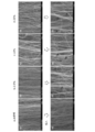
本発明による表面処理前後のカーボンナノチューブアレイの断面の走査顕微鏡写真を図3に示す。
表面処理によって、カーボンナノチューブの表面損傷や不純物が除去されるとともに結晶化が向上する。
本発明による表面処理前後のカーボンナノチューブアレイの断面の走査顕微鏡写真を図3に示す。
表面処理によって、カーボンナノチューブの表面損傷や不純物が除去されるとともに結晶化が向上する。
本発明の表面処理を同一の熱処理時間、異なる水素濃度で実施したカーボンナノチューブアレイの断面の走査顕微鏡写真を図4、水素濃度の異なるカーボンナノチューブの結晶化率の関係のグラフを図5に示す。
水素濃度10%、25%でそれぞれ表面処理したカーボンナノチューブアレイ(図4c、d)では、未処理のもの(図4a)と比較して結晶性も向上している。
また、それぞれの拡大写真の矢印で示す部分のように、隣接するカーボンナノチューブ同士が束状となっている箇所が多く見られることから、隣接するカーボンナノチューブの表面同士でファンデルワールス力が働くレベルまで表面特性が改善された、すなわち、界面強度が向上したことがわかる。
水素濃度10%、25%でそれぞれ表面処理したカーボンナノチューブアレイ(図4c、d)では、未処理のもの(図4a)と比較して結晶性も向上している。
また、それぞれの拡大写真の矢印で示す部分のように、隣接するカーボンナノチューブ同士が束状となっている箇所が多く見られることから、隣接するカーボンナノチューブの表面同士でファンデルワールス力が働くレベルまで表面特性が改善された、すなわち、界面強度が向上したことがわかる。
なお、水素濃度2.5%で表面処理したカーボンナノチューブアレイ(図4b)では、未処理のもの(図4a)と比較して、拡大写真の矢印で示す部分のように、表面特性は改善するものの、結晶性は別途の測定の結果むしろ低下していた。
また、水素濃度30%を超える領域で表面処理したカーボンナノチューブアレイ(図示せず)では、さらなる状態の変化はほとんど見られなかった。
また、水素濃度30%を超える領域で表面処理したカーボンナノチューブアレイ(図示せず)では、さらなる状態の変化はほとんど見られなかった。
これらの結果から、水素ガス濃度を制御することで、カーボンナノチューブの表面特性を制御でき界面強度を制御することができるとともに、結晶性を制御し表面損傷を制御できることがわかる。
また、水素ガス濃度が10%未満の場合、水素ガスとカーボンナノチューブの表面層との反応が充分に行われず、カーボンナノチューブの表面層の結晶性が低下し、むしろ結晶性が悪化することがわかった。
さらに、水素ガス濃度が30%を超えると、水素ガスとカーボンナノチューブの表面層との反応速度が早すぎ、熱処理時間を制御しても正確な表面処理プロセスの制御が難しくなることがわかった。
また、水素ガス濃度が10%未満の場合、水素ガスとカーボンナノチューブの表面層との反応が充分に行われず、カーボンナノチューブの表面層の結晶性が低下し、むしろ結晶性が悪化することがわかった。
さらに、水素ガス濃度が30%を超えると、水素ガスとカーボンナノチューブの表面層との反応速度が早すぎ、熱処理時間を制御しても正確な表面処理プロセスの制御が難しくなることがわかった。
本発明の表面処理を水素濃度10%、異なる熱処理時間で実施したカーボンナノチューブアレイの断面の走査顕微鏡写真を図6に示す(前述の図4に示すものとは、同じ条件で生成されたカーボンナノチューブアレイである。)。
表面処理を施さないカーボンナノチューブアレイ(図6a)と比較して、熱処理時間10分、20分、30分、60分でそれぞれ表面処理したカーボンナノチューブアレイ(図6b、c、d、e)では、カーボンナノチューブの結晶性も向上している。
また、それぞれの拡大写真のように、隣接するカーボンナノチューブ同士が束状となっている箇所が増加し、隣接するカーボンナノチューブの表面同士でファンデルワールス力が働くレベルまで表面特性が改善されたことがわかる。
表面処理を施さないカーボンナノチューブアレイ(図6a)と比較して、熱処理時間10分、20分、30分、60分でそれぞれ表面処理したカーボンナノチューブアレイ(図6b、c、d、e)では、カーボンナノチューブの結晶性も向上している。
また、それぞれの拡大写真のように、隣接するカーボンナノチューブ同士が束状となっている箇所が増加し、隣接するカーボンナノチューブの表面同士でファンデルワールス力が働くレベルまで表面特性が改善されたことがわかる。
また、それぞれの熱処理時間で表面処理したカーボンナノチューブアレイの表面特性、真直性、結晶性等が異なり、水素ガスの供給のオンオフのみで熱処理時間を容易に正確に制御可能であることから、用途に応じた所望の表面特性のカーボンナノチューブを得られることがわかった。
これらの結果から、熱処理時間を制御することで、カーボンナノチューブの表面特性を制御でき界面強度を制御することができるとともに、結晶性を制御し表面損傷を除去し、真直性を制御できることがわかる。
これらの結果から、熱処理時間を制御することで、カーボンナノチューブの表面特性を制御でき界面強度を制御することができるとともに、結晶性を制御し表面損傷を除去し、真直性を制御できることがわかる。
また、熱処理時間が10分未満の場合、全てのカーボンナノチューブの表面層で均一な反応とならない場合があるとともに、カーボンナノチューブの結晶性も向上しないことがわかった。
さらに、熱処理時間が60分を超えると、カーボンナノチューブの結晶性が低下し、表面特性が悪化するとともに、反応が表面層から奥のほうまで進み、カーボンナノチューブ自体の特性が悪化することがわかった。
さらに、熱処理時間が60分を超えると、カーボンナノチューブの結晶性が低下し、表面特性が悪化するとともに、反応が表面層から奥のほうまで進み、カーボンナノチューブ自体の特性が悪化することがわかった。
本発明の表面処理を異なる熱処理時間で実施したカーボンナノチューブそれを使用したカーボンナノチューブ・樹脂複合材料の断面の走査顕微鏡写真を図7に示す。
本実施形態でカーボンナノチューブ・樹脂複合材料に使用したカーボンナノチューブは、カーボンナノチューブアレイとして生成された多数のカーボンナノチューブを、端部から一方向に引いてシート状に成形することでカーボンナノチューブシートに加工されたものであり、カーボンナノチューブの表面処理はカーボンナノチューブアレイの状態で行ったものである。
またカーボンナノチューブ・樹脂複合材料に使用した樹脂はエポキシ樹脂である。
カーボンナノチューブの真直性、表面特性は、カーボンナノチューブシートに加工する際の紡績性に影響するとともに、カーボンナノチューブとエポキシ樹脂との反応性はカーボンナノチューブ・樹脂複合材料とした際界面強度及び、複合材の強度に大きな影響を与える。
本実施形態でカーボンナノチューブ・樹脂複合材料に使用したカーボンナノチューブは、カーボンナノチューブアレイとして生成された多数のカーボンナノチューブを、端部から一方向に引いてシート状に成形することでカーボンナノチューブシートに加工されたものであり、カーボンナノチューブの表面処理はカーボンナノチューブアレイの状態で行ったものである。
またカーボンナノチューブ・樹脂複合材料に使用した樹脂はエポキシ樹脂である。
カーボンナノチューブの真直性、表面特性は、カーボンナノチューブシートに加工する際の紡績性に影響するとともに、カーボンナノチューブとエポキシ樹脂との反応性はカーボンナノチューブ・樹脂複合材料とした際界面強度及び、複合材の強度に大きな影響を与える。
表面処理を施さないカーボンナノチューブを使用したカーボンナノチューブ・樹脂複合材料の断面(図7a)は、カーボンナノチューブが離脱した空洞部分(白い部分)が多く見られる。
これは、カーボンナノチューブの界面強度が低いことによりカーボンナノチューブとエポキシ樹脂の結合力が小さく、カーボンナノチューブ・樹脂複合材料としての強度も低くなることを示している。
熱処理時間10分、30分、60分でそれぞれ表面処理したカーボンナノチューブを使用したカーボンナノチューブ・樹脂複合材料の断面(図7b、c、d)は、カーボンナノチューブが離脱した空洞部分(白い部分)が少なくなっており、カーボンナノチューブの界面強度が高いことによりカーボンナノチューブとエポキシ樹脂の結合力が大きく、カーボンナノチューブ・樹脂複合材料としての強度も高くなることがわかる。
特に、熱処理時間30分で表面処理したカーボンナノチューブを使用したカーボンナノチューブ・樹脂複合材料の断面(図7c)で見られるような、端部が扇状に大きく拡がった部分(矢印で示す)は、カーボンナノチューブとエポキシ樹脂の結合力が極めて大きいことを示している。
これは、カーボンナノチューブの界面強度が低いことによりカーボンナノチューブとエポキシ樹脂の結合力が小さく、カーボンナノチューブ・樹脂複合材料としての強度も低くなることを示している。
熱処理時間10分、30分、60分でそれぞれ表面処理したカーボンナノチューブを使用したカーボンナノチューブ・樹脂複合材料の断面(図7b、c、d)は、カーボンナノチューブが離脱した空洞部分(白い部分)が少なくなっており、カーボンナノチューブの界面強度が高いことによりカーボンナノチューブとエポキシ樹脂の結合力が大きく、カーボンナノチューブ・樹脂複合材料としての強度も高くなることがわかる。
特に、熱処理時間30分で表面処理したカーボンナノチューブを使用したカーボンナノチューブ・樹脂複合材料の断面(図7c)で見られるような、端部が扇状に大きく拡がった部分(矢印で示す)は、カーボンナノチューブとエポキシ樹脂の結合力が極めて大きいことを示している。
以上のように、本発明によれば、不活性ガスと水素ガスを混合した雰囲気中で、所定の時間熱処理を行うこと、カーボンナノチューブの表面特性を変化させることができるため、カーボンナノチューブの強度を高め、界面強度を高め、紡績性を向上することが可能である。
また、この技術で最適に表面処理されたカーボンナノチューブを使用してアレイ、シート及び他の材料との複合材料とすることで、様々な用途の超軽量、超高強度の複合材への応用が可能となる。
また、この技術で最適に表面処理されたカーボンナノチューブを使用してアレイ、シート及び他の材料との複合材料とすることで、様々な用途の超軽量、超高強度の複合材への応用が可能となる。
Claims (9)
- カーボンナノチューブの表面処理方法であって、
不活性ガスと水素ガスを混合した雰囲気中で、所定の時間熱処理を行うことを特徴とするカーボンナノチューブの表面処理方法。 - 前記熱処理温度が、600℃乃至800℃の間の所定温度であり、
前記水素ガス濃度及び熱処理時間の一方または両方を制御することを特徴とする請求項1に記載のカーボンナノチューブの表面処理方法。 - 前記水素ガス濃度が、体積で10%乃至30%であることを特徴とする請求項1または請求項2に記載のカーボンナノチューブの表面処理方法。
- 前記熱処理時間が、10分乃至60分であることを特徴とする請求項1乃至請求項3のいずれかに記載のカーボンナノチューブの表面処理方法。
- 前記水素ガス濃度及び熱処理時間の一方または両方を制御することで、カーボンナノチューブの界面強度を制御することを特徴とする請求項2乃至請求項4のいずれかに記載のカーボンナノチューブの表面処理方法。
- 前記水素ガス濃度及び熱処理時間の一方または両方を制御することで、カーボンナノチューブの表面損傷を除去することを特徴とする請求項2乃至請求項5のいずれかに記載のカーボンナノチューブの表面処理方法。
- 請求項1乃至請求項6のいずれかに記載の製造方法により製造されたカーボンナノチューブアレイ。
- 請求項7に記載のカーボンナノチューブアレイからシート状に成型することを特徴とするカーボンナノチューブシート。
- 請求項8に記載のカーボンナノチューブシートと他の材料とが複合された複合材料。
Applications Claiming Priority (2)
| Application Number | Priority Date | Filing Date | Title |
|---|---|---|---|
| JP2014136147A JP6422149B2 (ja) | 2014-07-01 | 2014-07-01 | カーボンナノチューブの表面処理方法 |
| JP2014-136147 | 2014-07-01 |
Publications (1)
| Publication Number | Publication Date |
|---|---|
| WO2016002715A1 true WO2016002715A1 (ja) | 2016-01-07 |
Family
ID=55019247
Family Applications (1)
| Application Number | Title | Priority Date | Filing Date |
|---|---|---|---|
| PCT/JP2015/068681 Ceased WO2016002715A1 (ja) | 2014-07-01 | 2015-06-29 | カーボンナノチューブの表面処理方法 |
Country Status (2)
| Country | Link |
|---|---|
| JP (1) | JP6422149B2 (ja) |
| WO (1) | WO2016002715A1 (ja) |
Citations (7)
| Publication number | Priority date | Publication date | Assignee | Title |
|---|---|---|---|---|
| JP2001146409A (ja) * | 1999-10-11 | 2001-05-29 | Cheol Jin Lee | 炭素ナノチューブのチップオープン方法及び精製方法 |
| JP2005075725A (ja) * | 2003-09-01 | 2005-03-24 | Samsung Sdi Co Ltd | カーボンナノチューブ構造体及びその製造方法とそれを応用した電界放出素子及び表示装置 |
| WO2005102923A1 (ja) * | 2004-04-23 | 2005-11-03 | Sumitomo Electric Industries, Ltd. | カーボンナノ構造体の製造方法 |
| WO2010092787A1 (ja) * | 2009-02-10 | 2010-08-19 | 日本ゼオン株式会社 | カーボンナノチューブ配向集合体の製造装置 |
| JP2013234116A (ja) * | 2012-05-04 | 2013-11-21 | Qinghua Univ | カーボンナノチューブ構造体及びそれを利用した電界放出表示装置 |
| JP2014101233A (ja) * | 2012-11-16 | 2014-06-05 | Asahi Kasei Chemicals Corp | 表面処理カーボンナノチューブ |
| JP2014101401A (ja) * | 2012-11-16 | 2014-06-05 | Asahi Kasei Chemicals Corp | 多層カーボンナノチューブを含むポリアミド樹脂組成物 |
-
2014
- 2014-07-01 JP JP2014136147A patent/JP6422149B2/ja not_active Expired - Fee Related
-
2015
- 2015-06-29 WO PCT/JP2015/068681 patent/WO2016002715A1/ja not_active Ceased
Patent Citations (7)
| Publication number | Priority date | Publication date | Assignee | Title |
|---|---|---|---|---|
| JP2001146409A (ja) * | 1999-10-11 | 2001-05-29 | Cheol Jin Lee | 炭素ナノチューブのチップオープン方法及び精製方法 |
| JP2005075725A (ja) * | 2003-09-01 | 2005-03-24 | Samsung Sdi Co Ltd | カーボンナノチューブ構造体及びその製造方法とそれを応用した電界放出素子及び表示装置 |
| WO2005102923A1 (ja) * | 2004-04-23 | 2005-11-03 | Sumitomo Electric Industries, Ltd. | カーボンナノ構造体の製造方法 |
| WO2010092787A1 (ja) * | 2009-02-10 | 2010-08-19 | 日本ゼオン株式会社 | カーボンナノチューブ配向集合体の製造装置 |
| JP2013234116A (ja) * | 2012-05-04 | 2013-11-21 | Qinghua Univ | カーボンナノチューブ構造体及びそれを利用した電界放出表示装置 |
| JP2014101233A (ja) * | 2012-11-16 | 2014-06-05 | Asahi Kasei Chemicals Corp | 表面処理カーボンナノチューブ |
| JP2014101401A (ja) * | 2012-11-16 | 2014-06-05 | Asahi Kasei Chemicals Corp | 多層カーボンナノチューブを含むポリアミド樹脂組成物 |
Also Published As
| Publication number | Publication date |
|---|---|
| JP6422149B2 (ja) | 2018-11-14 |
| JP2016013943A (ja) | 2016-01-28 |
Similar Documents
| Publication | Publication Date | Title |
|---|---|---|
| Fan et al. | High efficient preparation of carbon nanotube-grafted carbon fibers with the improved tensile strength | |
| JP6963501B2 (ja) | 炭素系三次元材料端面を電気化学的酸化切断することで製造された酸化グラフェン及びその製造方法 | |
| Bazaka et al. | Oxygen plasmas: a sharp chisel and handy trowel for nanofabrication | |
| Hoyos-Palacio et al. | Catalytic effect of Fe, Ni, Co and Mo on the CNTs production | |
| Lee et al. | Synthesis of carbon nanotube fibers using the direct spinning process based on Design of Experiment (DOE) | |
| CN103145117B (zh) | 一种制备石墨烯的方法 | |
| Kim et al. | Synthesis of CVD-graphene on rapidly heated copper foils | |
| Riyajuddin et al. | Study of field emission properties of pure graphene-CNT heterostructures connected via seamless interface | |
| Kushkina et al. | Evolution of the multi-walled carbon nanotubes structure with increasing fluence of He ion irradiation | |
| JP7066254B2 (ja) | カーボンナノチューブ材料、その製造及び処理方法 | |
| CN104555994A (zh) | 奈米石墨烯空心粒子及其制作方法 | |
| Baddour et al. | Direct and repetitive growth cycles of carbon nanotubes on stainless steel particles by chemical vapor deposition in a fluidized bed | |
| Parveen et al. | Carbon nanotubes as emerging field emitters: Influencing factors and remedies | |
| JP6195109B2 (ja) | グラフェン分散液の製造方法およびグラフェン薄膜の製造方法 | |
| Zhang et al. | Enhanced field emission performance of holey expanded graphite by heat treatment | |
| Li et al. | Plasma functionalization for improving dispersion and interfacial bonding of multi-wall carbon nanotubes in cyanate ester/epoxy nanocomposites | |
| JP2019099989A (ja) | 炭素ナノ構造体の生成方法及び炭素ナノ構造体 | |
| Yin et al. | Postgrowth processing of carbon nanotube arrays-enabling new functionalities and applications | |
| JP6422149B2 (ja) | カーボンナノチューブの表面処理方法 | |
| Yip et al. | Fabrication Routes of Graphene | |
| Cole et al. | In-situ deposition of sparse vertically aligned carbon nanofibres on catalytically activated stainless steel mesh for field emission applications | |
| Zhang et al. | Confined-parallel-space in-situ growth method: a strategy for fabricating high-quality graphene-Cu composite with excellent comprehensive properties: T. Zhang et al. | |
| Xu et al. | Fe complex-based catalyst system for the chirality-selected continuous synthesis of single-walled carbon nanotubes | |
| Zou et al. | Refractory Vertically Aligned Carbon Nanotube–Boron Nitride Nanocomposites for Scalable Electrical Anisotropic Interconnects | |
| Wang et al. | Field emission characteristics of carbon nanotubes post-treated with high-density Ar plasma |
Legal Events
| Date | Code | Title | Description |
|---|---|---|---|
| 121 | Ep: the epo has been informed by wipo that ep was designated in this application |
Ref document number: 15815039 Country of ref document: EP Kind code of ref document: A1 |
|
| NENP | Non-entry into the national phase |
Ref country code: DE |
|
| 122 | Ep: pct application non-entry in european phase |
Ref document number: 15815039 Country of ref document: EP Kind code of ref document: A1 |