WO2016002438A1 - Gas sensor including sensor element, housing, and element cover - Google Patents
Gas sensor including sensor element, housing, and element cover Download PDFInfo
- Publication number
- WO2016002438A1 WO2016002438A1 PCT/JP2015/066382 JP2015066382W WO2016002438A1 WO 2016002438 A1 WO2016002438 A1 WO 2016002438A1 JP 2015066382 W JP2015066382 W JP 2015066382W WO 2016002438 A1 WO2016002438 A1 WO 2016002438A1
- Authority
- WO
- WIPO (PCT)
- Prior art keywords
- cover
- gas sensor
- housing
- sensor
- gas
- Prior art date
Links
Images


Classifications
-
- G—PHYSICS
- G01—MEASURING; TESTING
- G01N—INVESTIGATING OR ANALYSING MATERIALS BY DETERMINING THEIR CHEMICAL OR PHYSICAL PROPERTIES
- G01N27/00—Investigating or analysing materials by the use of electric, electrochemical, or magnetic means
- G01N27/26—Investigating or analysing materials by the use of electric, electrochemical, or magnetic means by investigating electrochemical variables; by using electrolysis or electrophoresis
- G01N27/403—Cells and electrode assemblies
- G01N27/406—Cells and probes with solid electrolytes
- G01N27/407—Cells and probes with solid electrolytes for investigating or analysing gases
- G01N27/4078—Means for sealing the sensor element in a housing
-
- G—PHYSICS
- G01—MEASURING; TESTING
- G01N—INVESTIGATING OR ANALYSING MATERIALS BY DETERMINING THEIR CHEMICAL OR PHYSICAL PROPERTIES
- G01N27/00—Investigating or analysing materials by the use of electric, electrochemical, or magnetic means
- G01N27/26—Investigating or analysing materials by the use of electric, electrochemical, or magnetic means by investigating electrochemical variables; by using electrolysis or electrophoresis
- G01N27/403—Cells and electrode assemblies
- G01N27/406—Cells and probes with solid electrolytes
- G01N27/407—Cells and probes with solid electrolytes for investigating or analysing gases
- G01N27/4077—Means for protecting the electrolyte or the electrodes
-
- G—PHYSICS
- G01—MEASURING; TESTING
- G01N—INVESTIGATING OR ANALYSING MATERIALS BY DETERMINING THEIR CHEMICAL OR PHYSICAL PROPERTIES
- G01N27/00—Investigating or analysing materials by the use of electric, electrochemical, or magnetic means
- G01N27/26—Investigating or analysing materials by the use of electric, electrochemical, or magnetic means by investigating electrochemical variables; by using electrolysis or electrophoresis
- G01N27/403—Cells and electrode assemblies
- G01N27/406—Cells and probes with solid electrolytes
- G01N27/4067—Means for heating or controlling the temperature of the solid electrolyte
-
- G—PHYSICS
- G01—MEASURING; TESTING
- G01N—INVESTIGATING OR ANALYSING MATERIALS BY DETERMINING THEIR CHEMICAL OR PHYSICAL PROPERTIES
- G01N27/00—Investigating or analysing materials by the use of electric, electrochemical, or magnetic means
- G01N27/26—Investigating or analysing materials by the use of electric, electrochemical, or magnetic means by investigating electrochemical variables; by using electrolysis or electrophoresis
- G01N27/403—Cells and electrode assemblies
- G01N27/406—Cells and probes with solid electrolytes
- G01N27/407—Cells and probes with solid electrolytes for investigating or analysing gases
- G01N27/4071—Cells and probes with solid electrolytes for investigating or analysing gases using sensor elements of laminated structure
-
- G—PHYSICS
- G01—MEASURING; TESTING
- G01N—INVESTIGATING OR ANALYSING MATERIALS BY DETERMINING THEIR CHEMICAL OR PHYSICAL PROPERTIES
- G01N27/00—Investigating or analysing materials by the use of electric, electrochemical, or magnetic means
- G01N27/26—Investigating or analysing materials by the use of electric, electrochemical, or magnetic means by investigating electrochemical variables; by using electrolysis or electrophoresis
- G01N27/403—Cells and electrode assemblies
- G01N27/406—Cells and probes with solid electrolytes
- G01N27/407—Cells and probes with solid electrolytes for investigating or analysing gases
- G01N27/4075—Composition or fabrication of the electrodes and coatings thereon, e.g. catalysts
- G01N27/4076—Reference electrodes or reference mixtures
-
- G—PHYSICS
- G01—MEASURING; TESTING
- G01N—INVESTIGATING OR ANALYSING MATERIALS BY DETERMINING THEIR CHEMICAL OR PHYSICAL PROPERTIES
- G01N27/00—Investigating or analysing materials by the use of electric, electrochemical, or magnetic means
- G01N27/26—Investigating or analysing materials by the use of electric, electrochemical, or magnetic means by investigating electrochemical variables; by using electrolysis or electrophoresis
- G01N27/403—Cells and electrode assemblies
- G01N27/406—Cells and probes with solid electrolytes
- G01N27/407—Cells and probes with solid electrolytes for investigating or analysing gases
- G01N27/409—Oxygen concentration cells
Definitions
- the present disclosure relates to a gas sensor that detects a specific gas concentration in a gas to be measured.
- An exhaust system such as an internal combustion engine for a vehicle is provided with a gas sensor that detects a specific gas concentration (for example, oxygen concentration) in a gas to be measured such as exhaust gas.
- a gas sensor includes a sensor element having a solid electrolyte body, a measurement electrode and a reference electrode provided on one surface and the other surface of the solid electrolyte body, a housing through which the sensor element is inserted, and the housing And an element cover disposed on the front end side of the.
- Japanese Patent Application Laid-Open No. 2000-171429 has an inner cover arranged to cover the tip of the sensor element from the outside and an outer cover arranged to cover the inner cover from the outside as the element cover.
- a gas sensor is disclosed.
- the gas sensor is attached to an exhaust pipe or the like of the internal combustion engine at a mounting screw portion formed in the housing. Further, in the gas sensor, a portion on the front end side with respect to the housing is disposed in the flow path of the gas to be measured, and a portion on the proximal end side with respect to the housing is disposed outside the flow path. Therefore, a seal member filled with talc or the like is provided between the sensor element and the housing in order to ensure airtightness.
- the present disclosure has been made in view of the above circumstances, and provides a gas sensor that can improve the detection accuracy by suppressing the influence of air leakage at the seal portion between the sensor element and the housing.
- One embodiment of the present disclosure includes an oxygen ion conductive solid electrolyte body, a sensor element having a measurement electrode and a reference electrode provided on one surface and the other surface of the solid electrolyte body, and the sensor element inside
- a gas sensor comprising: a housing that is inserted into the housing; and an element cover disposed on a distal end side of the housing, wherein the element cover is disposed so as to cover the distal end portion of the sensor element from the outside.
- an outer cover disposed so as to cover the inner cover from the outside, and when the axial distance between the base end of the inner space of the inner cover and the base end of the measurement electrode is L, The axial distance between the proximal end of the inner space of the inner cover and the proximal end of the innermost vent hole provided in the inner cover is 0.2L to 0.65L. That is In the gas sensor for the butterflies.
- the axial distance between the proximal end of the inner space of the inner cover and the proximal end of the inner vent hole closest to the proximal end is 0.2 L to 0.65 L. That is, the position of the inner vent hole is provided at a position that is more distal than the proximal end of the inner space and sufficiently away from the measurement electrode toward the proximal end. Accordingly, when air enters the inner space of the inner cover from between the sensor element and the housing, it is possible to suppress the air from further moving toward the measurement electrode. That is, it is possible to prevent the movement of air to the tip side by the gas to be measured flowing into the inner space from the outside through the inner vent hole. As a result, it is possible to prevent the oxygen concentration in the measurement gas on the surface of the measurement electrode from changing, and to improve the detection accuracy of the gas sensor.
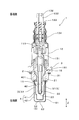
- FIG. 3 is a cross-sectional view of the gas sensor in the first embodiment.
- FIG. 3 is a partial cross-sectional explanatory view around the element cover of the gas sensor in the first embodiment.
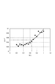
- FIG. The diagram which shows the relationship between M / L and stoichiometric deviation ((DELTA) A / F) in an experiment example.
- the gas sensor is used in an exhaust system such as an internal combustion engine for a vehicle.
- the side where the gas sensor is inserted into the exhaust system or the like is referred to as the distal end side, and the opposite side is referred to as the proximal end side.
- the axial direction refers to the axial direction of the gas sensor unless otherwise specified.
- the gas sensor 1 of the present example includes a sensor element 2, a housing 3 through which the sensor element 2 is inserted, and an element cover 4 disposed on the front end side of the housing 3. .
- the sensor element 2 includes an oxygen ion conductive solid electrolyte body 21, and a measurement electrode 22 and a reference electrode 23 provided on one surface and the other surface of the solid electrolyte body 21, respectively.
- the element cover 4 includes an inner cover 41 disposed so as to cover the tip of the sensor element 2 from the outside, and an outer cover 42 disposed so as to cover the inner cover 41 from the outside.
- the base end 401 of the inner space 40 of the inner cover 41 when the axial distance between the base end 401 of the inner space 40 of the inner cover 41 and the base end of the measurement electrode 22 is L, the base end 401 of the inner space 40 of the inner cover 41;
- the axial distance between the inner vent hole 5 provided in the inner cover 41 and the proximal end of the innermost vent hole 5 (inner side hole 51) is M.
- the axial distance M is 0.2L to 0.65L. That is, the axial distances M and L in the gas sensor 1 satisfy 0.2 ⁇ M / L ⁇ 0.65.
- the base end 401 of the inner space 40 is the front end of the housing 3 on the inner peripheral side of the inner cover 41.
- the inner cover 41 has an inner side hole 51 as an inner vent hole 5 in the inner side wall portion 411 along the axial direction Z.
- the outer cover 42 has an outer side surface hole 61 in the outer side wall portion 421 along the axial direction Z.
- the outer side surface hole 61 is located on the front end side with respect to the inner side surface hole 51.
- the sensor element 2 is a bottomed cylindrical cup type in which the distal end side is closed and the proximal end side is opened. That is, the solid electrolyte body 21 has a bottomed cylindrical cup shape as described above. And the measurement electrode 22 is formed in the outer surface, and the reference electrode 23 is formed in the inner surface.
- the main component of the solid electrolyte body 21 is zirconia.
- the measurement electrode 22 and the reference electrode 23 are both preferably composed of a platinum group element, and in this example, are composed of platinum.
- the reference electrode 23 is formed on substantially the entire inner surface of the solid electrolyte body 21.
- the measurement electrode 22 is provided in a part of the solid electrolyte body 21 near the tip.
- the distal end of the measurement electrode 22 is located on the proximal end side with respect to the distal end of the solid electrolyte body 21.
- the measurement electrode 22 is formed in the whole circumferential direction.
- the gas sensor 1 has an atmosphere-side cover 12 fixed to the base end side of the housing 3.
- the base end side of the sensor element 2 is opened inside the atmosphere side cover 12.
- a terminal member 131 that is electrically connected to the measurement electrode 22 and the reference electrode 23 is disposed at the base end of the sensor element 2.
- a heater 11 for heating the sensor element 2 is disposed inside the sensor element 2.
- a lead wire 132 made of a covered conductor is connected to the terminal member 131 and the terminal portion 111 of the heater 11. The lead wire 132 is drawn out from the base end portion of the atmosphere side cover 12 through the bush 133.
- the atmosphere-side cover 12 has an atmosphere introduction part 134 for introducing the atmosphere (air) as a reference gas from the outside to the inside space. The air is guided to the space inside the atmosphere side cover 12 through the atmosphere introduction part 134 while removing moisture and the like, and further introduced into the sensor element 2 to reach the surface of the reference electrode 23.
- a seal member 151 formed by filling talc is provided in the seal portion 15 between the sensor element 2 and the housing 3.
- the seal part 15 between the sensor element 2 and the housing 3 has airtightness such that the amount of air leakage when air pressure of 1 MPa is applied is 0.005 to 5 ml / min. In other words, this airtightness passes through the seal portion 15 when air is supplied from the atmosphere side space (the space inside the atmosphere side cover 12) to the seal portion 15 at a pressure of 1 MPa.
- the amount per unit time of the air leaking to the measurement gas side (inside space 40 side) can be obtained by measuring with an air leak tester.
- the housing 3 is formed with a mounting screw portion 31 for mounting the gas sensor 1 to an exhaust pipe or the like.
- the element cover 4 is caulked and fixed to the distal end portion of the housing 3 at flange portions 413 and 423 at the proximal end thereof.
- the inner cover 41 and the outer cover 42 are caulked and fixed to the housing 3 in a state where the flange portions 413 and 423 are overlapped with each other.
- the inner cover 41 has an inclined surface portion 414 between the flange portion 413 and the inner side wall portion 411.
- the inner side surface hole 51 is formed in the inner side wall portion 411 on the tip side of the inclined surface portion 414. That is, the inner side surface hole 51 is formed at a position between the inclined surface portion 414 and the measurement electrode 22 in the axial direction Z. As shown in FIG. 3, a plurality of inner side surface holes 51 are formed at equal intervals in the circumferential direction.
- a diameter-reduced portion 415 that is reduced inward is provided on the distal end side of the inner side wall portion 411, and an inner bottom wall portion 412 that is substantially orthogonal to the axial direction is provided on the distal end side of the reduced-diameter portion 415. Yes.
- An inner bottom hole 52 is formed in the inner bottom wall portion 412 as the inner vent hole 5.
- the outer side wall portion 421 of the outer cover 42 is formed to extend from the flange portion 423 toward the distal end side.
- An outer bottom wall 422 is formed so as to be connected to the tip of the outer side wall 421 and to be orthogonal to the axial direction Z.
- the outer side surface hole 61 formed in the outer side wall portion 421 is a plurality of the outer side surface holes 61 at the front end side of the inner side surface hole 51 and at the front end side of the sensor element 2 at equal intervals in the circumferential direction. Individually distributed.
- an outer bottom hole 62 is formed in the outer bottom wall portion 422.
- the inner bottom hole 52, the outer bottom hole 62, the inner side hole 51, and the outer side hole 61 are all circular holes.
- a clearance is formed between the inner side wall portion 411 and the outer side wall portion 421, and a clearance is also formed between the inner bottom wall portion 412 and the outer bottom wall portion 422.
- the inner side wall portion 411 and the outer side wall portion 421 are formed in a substantially cylindrical shape so as to share the central axis and the central axis of the sensor element 2 along the outer peripheral surface of the bottomed cylindrical sensor element 2. Yes.
- the gas sensor 1 of this example is a rear gas sensor installed on the downstream side of the catalyst filter in the exhaust system of the internal combustion engine. Further, the gas sensor 1 of this example applies a predetermined voltage between the measurement electrode 22 and the reference electrode 23, thereby limiting the limit current value depending on the specific gas concentration (oxygen concentration) in the gas to be measured (exhaust gas). Is a limiting current type gas sensor.
- the gas sensor 1 is disposed downstream of the catalytic filter that purifies the exhaust gas in the exhaust system of the automobile engine. And the limiting current value depending on the oxygen concentration in the exhaust gas after passing through the catalyst filter is output. Based on the obtained limit current value, the air-fuel ratio in the air-fuel mixture supplied to the internal combustion engine can be calculated and fed back to the engine control system.
- the axial distance M between the base end 401 of the inner space 40 and the base end of the inner side surface hole 51 is 0.2L to 0.65L. That is, the inner side surface hole 51 is provided at a position farther from the base end 401 of the inner space 40 and sufficiently away from the measurement electrode 22 toward the base end side.
- the air A is further prevented from moving toward the measurement electrode 22. can do. That is, the movement of the air A toward the tip end side can be prevented by the measurement gas G flowing into the inner space 40 from the outside through the inner side surface hole 51.
- the oxygen concentration in the measurement gas G on the surface of the measurement electrode 22 can be prevented from changing, and the detection accuracy of the gas sensor 1 can be improved.
- the outer side hole 61 is located on the tip side of the inner side hole 51. Accordingly, when the gas to be measured G is introduced from the outer side surface hole 61 between the outer cover 42 and the inner cover 41, an air flow is generated from the outer side surface hole 61 toward the inner side surface hole 51. Therefore, even when the measurement gas G flows from the inner side surface hole 51 into the inner space 40, an air flow toward the base end side is easily generated. That is, near the inner side surface hole 51 in the inner space 40, an air flow G1 toward the base end 401 of the inner space 40 also exists. Therefore, even if the air A leaks from the base end 401 to the inner space 40, the air A can be kept to the base end side by the air flow G1.
- the air A can be prevented from moving to the vicinity of the measurement electrode 22.
- the outer side surface hole 61 is positioned on the front end side of the inner side surface hole 51, the influence of air leakage between the sensor element 2 and the housing 3 can be effectively suppressed.
- the gas sensor 1 is a rear gas sensor installed on the downstream side of the catalyst filter in the exhaust system of the internal combustion engine. Therefore, although the level of detection accuracy required for the gas sensor 1 is particularly high, the above configuration can meet the requirement.
- the gas sensor 1 is a limiting current type gas sensor, high detection accuracy (stoichiometric accuracy) can be obtained.
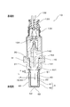
- Example 2 This example is an example of the gas sensor 10 using the laminated sensor element 20 as shown in FIG. That is, the sensor element 20 in the gas sensor 10 of the present example has a plate bar shape, and a tip portion thereof is disposed inside the element cover 4.
- the sensor element 20 is configured by laminating other ceramic layers in the thickness direction of the plate-shaped solid electrolyte body.
- a heater (not shown) is also integrated with the sensor element 20.
- a measuring electrode 22 is provided at the tip of the sensor element 20.
- a reference electrode (not shown) is formed inside the sensor element 20.
- the sensor element 20 is held inside the housing 3 via an insulator 141. That is, the sensor element 20 is inserted and held inside the insulator 141, and the insulator 141 is inserted and held inside the housing 3. A part between the sensor element 20 and the insulator 141 is sealed with a glass sealing portion 142.
- a ring-shaped seal member 152 is provided in a part between the insulator 141 and the housing 3.
- the seal member 152 prevents air leakage between the insulator 141 and the housing 3, that is, between the sensor element 20 and the housing 3.
- the seal portion 15 between the sensor element 20 and the housing 3 is a portion between the insulator 141 and the housing 3, and is hermetically sealed by the seal member 152.
- the gas sensor 10 of this example has substantially the same structure and function as the gas sensor 1 of the first embodiment.
- the same reference numerals as those used in the first embodiment denote the same components as in the first embodiment unless otherwise specified.
- the element cover 4 has an inner cover 41 and an outer cover 42.
- the inner cover 41 has an inner vent hole 5 (an inner side hole 51 and an inner bottom hole 52), and the outer cover 42 has an outer side hole 61 and an outer bottom hole 62.
- the shapes of the inner cover 41 and the outer cover 42 are partially different from those shown in the first embodiment, but in this example, the shapes shown in the first embodiment can also be adopted.
- the axial distance M is 0.2L to 0.65L.
- L is the axial distance between the base end 401 of the inner space 40 of the inner cover 41 and the base end of the measurement electrode 22 as in the first embodiment.
- gas sensor 10 including the stacked sensor element 20 as in the present example it is possible to obtain the same effects as in the first embodiment.
- Example 5 In this example, as shown in FIG. 5, the relationship between the ratio (M / L) of the axial distance M to the axial distance L shown in Example 1 and the detection accuracy of the gas sensor was examined.
- the gas sensor used as the sample has the same basic configuration as the gas sensor 1 of the first embodiment. Then, by changing the position of the inner side surface hole 51 in the axial direction Z in various ways, the axial distance M was changed in various ways to prepare a plurality of types of gas sensors. Moreover, the dimension of each part of the element cover 4 in the gas sensor used for this example, the position of the measurement electrode 22 of the sensor element 2, etc. are as follows.
- the axial distance L from the base end 401 of the inner space 40 to the base end of the measurement electrode 22 was 9.3 mm.
- the axial length of the measurement electrode 22 was 2 mm.
- the axial distance from the base end 401 to the front end of the inner cover 41 was 20 mm.
- the axial distance from the base end 401 to the front end of the outer cover 42 was 22.5 mm.
- the axial distance from the base end 401 to the base end of the outer side surface hole 61 was 18.5 mm.
- the inner side holes 51 are circular with a diameter of 2 mm, and six are formed.
- the outer side hole 61 is a circle having a diameter of 2 mm, and six outer side holes 61 are formed.
- One inner bottom hole 52 is a circle having a diameter of 2 mm, and one inner bottom hole 52 is a circle having a diameter of 2 mm and one is formed. Both the inner cover 41 and the outer cover 42 have a thickness of 0.5 mm. The clearance between the inner side wall part 411 and the outer side wall part 421 was 2 mm. The airtightness of the seal portion 15 is such that the amount of air leakage when an air pressure of 1 MPa is applied is 0.01 ml / min.
Abstract
A gas sensor (1) is provided with: a sensor element (2) having a solid electrolyte body (21), a measurement electrode (22), and a reference electrode (23); a housing (3) having the sensor element (2) inserted therein; and an element cover (4) provided on the distal-end side of the housing (3). The element cover (4) has an inner cover (41) disposed so as to cover a distal-end part of the sensor element (2) from the outside and an outer cover (42) disposed so as to cover the inner cover (41) from the outside. The axial distance (M) from the proximal end (401) of the internal space (40) of the inner cover (41) to the proximal end of the inner ventilation hole (5) furthest to the proximal-end side from among inner ventilation holes (5) provided in the inner cover (41) is 0.2L to 0.65L, where L is the axial distance from the proximal end (401) of the internal space (40) of the inner cover (41) to the proximal end of the measurement electrode (22).
Description
本開示は、被測定ガス中の特定ガス濃度を検出するガスセンサに関する。
The present disclosure relates to a gas sensor that detects a specific gas concentration in a gas to be measured.
車両用の内燃機関等の排気系には、排ガス等の被測定ガス中における特定ガス濃度(例えば、酸素濃度)を検出するガスセンサが配設されている。かかるガスセンサは、固体電解質体と該固体電解質体の一方の面と他方の面とにそれぞれ設けた測定電極及び基準電極とを有するセンサ素子と、該センサ素子を内側に挿通するハウジングと、該ハウジングの先端側に配設された素子カバーとを備えている。例えば、特開2000-171429号公報では素子カバーとして、センサ素子の先端部を外側から覆うように配設されたインナカバーと、該インナカバーを外側から覆うように配設されたアウタカバーとを有するガスセンサを開示している。
An exhaust system such as an internal combustion engine for a vehicle is provided with a gas sensor that detects a specific gas concentration (for example, oxygen concentration) in a gas to be measured such as exhaust gas. Such a gas sensor includes a sensor element having a solid electrolyte body, a measurement electrode and a reference electrode provided on one surface and the other surface of the solid electrolyte body, a housing through which the sensor element is inserted, and the housing And an element cover disposed on the front end side of the. For example, Japanese Patent Application Laid-Open No. 2000-171429 has an inner cover arranged to cover the tip of the sensor element from the outside and an outer cover arranged to cover the inner cover from the outside as the element cover. A gas sensor is disclosed.
ガスセンサは、ハウジングに形成された取り付け用ねじ部において、内燃機関の排気管等に取り付けられる。また、ガスセンサは、ハウジングよりも先端側の部分が被測定ガスの流路に配置され、ハウジングよりも基端側の部分が上記流路の外に配置される。したがって、センサ素子とハウジングとの間には、気密性を確保するために、タルク等を充填したシール部材が設けてある。
The gas sensor is attached to an exhaust pipe or the like of the internal combustion engine at a mounting screw portion formed in the housing. Further, in the gas sensor, a portion on the front end side with respect to the housing is disposed in the flow path of the gas to be measured, and a portion on the proximal end side with respect to the housing is disposed outside the flow path. Therefore, a seal member filled with talc or the like is provided between the sensor element and the housing in order to ensure airtightness.
しかしながら、センサ素子とハウジングとの間のシール部の気密性が低いと、この部分から空気(大気)がハウジングの先端側へ漏れることが考えられる。それにより、空気はインナカバーの内側に侵入する。この空気がインナカバー内においてさらに先端側へ移動すると、センサ素子の測定電極付近において、被測定ガス中の酸素濃度が変化してしまう。その結果、ガスセンサによって検出される特定ガス濃度に誤差が生じてしまうおそれがある。
However, if the hermeticity of the seal portion between the sensor element and the housing is low, air (atmosphere) may leak from this portion to the front end side of the housing. Thereby, air penetrates into the inner cover. When this air further moves to the tip side in the inner cover, the oxygen concentration in the gas to be measured changes in the vicinity of the measurement electrode of the sensor element. As a result, an error may occur in the specific gas concentration detected by the gas sensor.
詳しくは、例えば、理想的な空燃比である混合気の排ガス、すなわちストイキの排ガスをガスセンサによって測定したときに、上記の空気漏れが影響し、ストイキからずれた値が測定されてしまう。したがって、内燃機関のフィードバックシステムにガスセンサを用いたときに、その制御システムを正確に機能させることができなくなるおそれがある。
More specifically, for example, when an exhaust gas of an air-fuel mixture having an ideal air-fuel ratio, that is, a stoichiometric exhaust gas is measured by a gas sensor, the above-described air leakage affects and a value deviated from the stoichiometry is measured. Therefore, when the gas sensor is used in the feedback system of the internal combustion engine, there is a possibility that the control system cannot function correctly.
この点、シール部における気密性を向上させることが求められるが、空気の漏れを完全に防ぐことは困難である。それゆえ、より高精度の特定ガス濃度の検出が求められる場合には、シール部の気密性を高めるだけの対策では充分ではなかった。
In this respect, it is required to improve the airtightness in the seal portion, but it is difficult to completely prevent air leakage. Therefore, when it is required to detect the specific gas concentration with higher accuracy, it is not sufficient to take measures to improve the hermeticity of the seal portion.
本開示は、上記の事情に鑑みてなされたものであり、センサ素子とハウジングとの間のシール部における空気漏れの影響を抑制して、検出精度を向上させることができるガスセンサを提供する。
The present disclosure has been made in view of the above circumstances, and provides a gas sensor that can improve the detection accuracy by suppressing the influence of air leakage at the seal portion between the sensor element and the housing.
本開示の一態様は、酸素イオン伝導性の固体電解質体と該固体電解質体の一方の面と他方の面とにそれぞれ設けた測定電極及び基準電極とを有するセンサ素子と、該センサ素子を内側に挿通するハウジングと、該ハウジングの先端側に配設された素子カバーと、を備えるガスセンサであって、該素子カバーは、上記センサ素子の先端部を外側から覆うように配設されたインナカバーと、該インナカバーを外側から覆うように配設されたアウタカバーとを有し、上記インナカバーの内側空間の基端と上記測定電極の基端との間の軸方向距離をLとしたとき、上記インナカバーの内側空間の基端と、上記インナカバーに設けられたインナ通気孔のうち最も基端側のインナ通気孔の基端との間の軸方向距離は、0.2L~0.65Lであることを特徴とするガスセンサにある。
One embodiment of the present disclosure includes an oxygen ion conductive solid electrolyte body, a sensor element having a measurement electrode and a reference electrode provided on one surface and the other surface of the solid electrolyte body, and the sensor element inside A gas sensor comprising: a housing that is inserted into the housing; and an element cover disposed on a distal end side of the housing, wherein the element cover is disposed so as to cover the distal end portion of the sensor element from the outside. And an outer cover disposed so as to cover the inner cover from the outside, and when the axial distance between the base end of the inner space of the inner cover and the base end of the measurement electrode is L, The axial distance between the proximal end of the inner space of the inner cover and the proximal end of the innermost vent hole provided in the inner cover is 0.2L to 0.65L. That is In the gas sensor for the butterflies.
上記ガスセンサにおいては、インナカバーの内側空間の基端と、最も基端側のインナ通気孔の基端との間の軸方向の距離が、0.2L~0.65Lである。つまり、内側空間の基端よりも先端側であり、かつ、測定電極から基端側に充分に離れた位置に、インナ通気孔の位置を設けている。これにより、センサ素子とハウジングとの間からインナカバーの内側空間に空気が侵入したとき、空気がさらに測定電極へ向かって移動することを抑制することができる。つまり、インナ通気孔を通じて外側から内側空間に流入する被測定ガスによって、先端側への空気の移動を阻止することができる。その結果、測定電極の表面における被測定ガス中の酸素濃度が変化することを防ぎ、ガスセンサの検出精度を向上させることができる。
In the above gas sensor, the axial distance between the proximal end of the inner space of the inner cover and the proximal end of the inner vent hole closest to the proximal end is 0.2 L to 0.65 L. That is, the position of the inner vent hole is provided at a position that is more distal than the proximal end of the inner space and sufficiently away from the measurement electrode toward the proximal end. Accordingly, when air enters the inner space of the inner cover from between the sensor element and the housing, it is possible to suppress the air from further moving toward the measurement electrode. That is, it is possible to prevent the movement of air to the tip side by the gas to be measured flowing into the inner space from the outside through the inner vent hole. As a result, it is possible to prevent the oxygen concentration in the measurement gas on the surface of the measurement electrode from changing, and to improve the detection accuracy of the gas sensor.
以上のごとく、本開示によれば、センサ素子とハウジングとの間のシール部における空気漏れの影響を抑制して、検出精度を向上させることができるガスセンサを提供することができる。
As described above, according to the present disclosure, it is possible to provide a gas sensor that can improve the detection accuracy by suppressing the influence of air leakage at the seal portion between the sensor element and the housing.
添付図面において:
本開示の実施例1における、ガスセンサの素子カバー周辺の断面図。
実施例1における、ガスセンサの断面図。
実施例1における、ガスセンサの素子カバー周辺の一部断面説明図。
実施例2における、ガスセンサの断面図。
実験例における、M/Lとストイキずれ(ΔA/F)との関係を示す線図。
In the attached drawing:
Sectional drawing of the element cover periphery of the gas sensor in Example 1 of this indication. FIG. 3 is a cross-sectional view of the gas sensor in the first embodiment. FIG. 3 is a partial cross-sectional explanatory view around the element cover of the gas sensor in the first embodiment. Sectional drawing of the gas sensor in Example 2. FIG. The diagram which shows the relationship between M / L and stoichiometric deviation ((DELTA) A / F) in an experiment example.
上記ガスセンサは、例えば、車両用の内燃機関等の排気系に配設して用いられる。
なお、本明細書において、ガスセンサを排気系等に挿入する側を先端側、その反対側を基端側という。また、軸方向とは、特に言及しない限り、ガスセンサの軸方向をいうものとする。 The gas sensor is used in an exhaust system such as an internal combustion engine for a vehicle.
In this specification, the side where the gas sensor is inserted into the exhaust system or the like is referred to as the distal end side, and the opposite side is referred to as the proximal end side. The axial direction refers to the axial direction of the gas sensor unless otherwise specified.
(実施例1)
上記ガスセンサの実施例につき、図1~図3を用いて説明する。
本例のガスセンサ1は、図1、図2に示すごとく、センサ素子2と、センサ素子2を内側に挿通するハウジング3と、ハウジング3の先端側に配設された素子カバー4と、を備える。センサ素子2は、酸素イオン伝導性の固体電解質体21と該固体電解質体21の一方の面と他方の面とにそれぞれ設けた測定電極22及び基準電極23とを有する。 (Example 1)
An embodiment of the gas sensor will be described with reference to FIGS.
As shown in FIGS. 1 and 2, thegas sensor 1 of the present example includes a sensor element 2, a housing 3 through which the sensor element 2 is inserted, and an element cover 4 disposed on the front end side of the housing 3. . The sensor element 2 includes an oxygen ion conductive solid electrolyte body 21, and a measurement electrode 22 and a reference electrode 23 provided on one surface and the other surface of the solid electrolyte body 21, respectively.
上記ガスセンサの実施例につき、図1~図3を用いて説明する。
本例のガスセンサ1は、図1、図2に示すごとく、センサ素子2と、センサ素子2を内側に挿通するハウジング3と、ハウジング3の先端側に配設された素子カバー4と、を備える。センサ素子2は、酸素イオン伝導性の固体電解質体21と該固体電解質体21の一方の面と他方の面とにそれぞれ設けた測定電極22及び基準電極23とを有する。 (Example 1)
An embodiment of the gas sensor will be described with reference to FIGS.
As shown in FIGS. 1 and 2, the
素子カバー4は、センサ素子2の先端部を外側から覆うように配設されたインナカバー41と、インナカバー41を外側から覆うように配設されたアウタカバー42とを有する。
The element cover 4 includes an inner cover 41 disposed so as to cover the tip of the sensor element 2 from the outside, and an outer cover 42 disposed so as to cover the inner cover 41 from the outside.
図1に示すごとく、インナカバー41の内側空間40の基端401と測定電極22の基端との間の軸方向距離をLとしたとき、インナカバー41の内側空間40の基端401と、インナカバー41に設けられたインナ通気孔5のうち最も基端側のインナ通気孔5(インナ側面孔51)の基端との間の軸方向距離はMである。軸方向の距離Mは0.2L~0.65Lである。すなわち、ガスセンサ1における上記軸方向距離M及びLは、0.2≦M/L≦0.65を満たしている。なお、内側空間40の基端401は、インナカバー41の内周側におけるハウジング3の先端である。
As shown in FIG. 1, when the axial distance between the base end 401 of the inner space 40 of the inner cover 41 and the base end of the measurement electrode 22 is L, the base end 401 of the inner space 40 of the inner cover 41; The axial distance between the inner vent hole 5 provided in the inner cover 41 and the proximal end of the innermost vent hole 5 (inner side hole 51) is M. The axial distance M is 0.2L to 0.65L. That is, the axial distances M and L in the gas sensor 1 satisfy 0.2 ≦ M / L ≦ 0.65. The base end 401 of the inner space 40 is the front end of the housing 3 on the inner peripheral side of the inner cover 41.
また、インナカバー41は、軸方向Zに沿ったインナ側壁部411にインナ側面孔51をインナ通気孔5として有する。アウタカバー42は、軸方向Zに沿ったアウタ側壁部421にアウタ側面孔61を有する。そして、アウタ側面孔61は、インナ側面孔51よりも先端側に位置している。
The inner cover 41 has an inner side hole 51 as an inner vent hole 5 in the inner side wall portion 411 along the axial direction Z. The outer cover 42 has an outer side surface hole 61 in the outer side wall portion 421 along the axial direction Z. The outer side surface hole 61 is located on the front end side with respect to the inner side surface hole 51.
図2に示すごとく、センサ素子2は、先端側が閉塞されると共に基端側が開放された有底筒状のコップ型である。すなわち、固体電解質体21が、上記のような有底筒状のコップ型の形状を有している。そして、その外側面に測定電極22が形成されており、内側面に基準電極23が形成されている。
As shown in FIG. 2, the sensor element 2 is a bottomed cylindrical cup type in which the distal end side is closed and the proximal end side is opened. That is, the solid electrolyte body 21 has a bottomed cylindrical cup shape as described above. And the measurement electrode 22 is formed in the outer surface, and the reference electrode 23 is formed in the inner surface.
固体電解質体21の主成分はジルコニアである。また、測定電極22及び基準電極23は、何れも白金族元素で構成されることが好ましく、特に本例においては、白金からなる。
The main component of the solid electrolyte body 21 is zirconia. The measurement electrode 22 and the reference electrode 23 are both preferably composed of a platinum group element, and in this example, are composed of platinum.
基準電極23は、固体電解質体21の内側面の略全面に形成されている。一方、測定電極22は、固体電解質体21における先端部付近の一部に設けられている。ただし、本例においては、測定電極22の先端は、固体電解質体21の先端よりも基端側に位置する。また、測定電極22は、周方向の全体に形成されている。
The reference electrode 23 is formed on substantially the entire inner surface of the solid electrolyte body 21. On the other hand, the measurement electrode 22 is provided in a part of the solid electrolyte body 21 near the tip. However, in this example, the distal end of the measurement electrode 22 is located on the proximal end side with respect to the distal end of the solid electrolyte body 21. Moreover, the measurement electrode 22 is formed in the whole circumferential direction.
図2に示すごとく、ガスセンサ1は、ハウジング3の基端側に大気側カバー12を固定してなる。センサ素子2の基端側は、大気側カバー12の内側において開口している。センサ素子2の基端部には、測定電極22及び基準電極23にそれぞれ電気的に接続された端子部材131が配設されている。また、センサ素子2の内側には、センサ素子2を加熱するためのヒータ11が配設されている。端子部材131及びヒータ11の端子部111には、それぞれ被覆導線からなるリード線132が接続されている。リード線132は、大気側カバー12の基端部からブッシュ133を通して外部へ引き出されている。また、大気側カバー12には、外部から内側の空間に大気(空気)を基準ガスとして導入するための大気導入部134を有する。空気は、この大気導入部134を介して、水分等を除去されながら大気側カバー12の内側の空間に導かれ、さらにはセンサ素子2の内側に導入され、基準電極23の表面に達する。
As shown in FIG. 2, the gas sensor 1 has an atmosphere-side cover 12 fixed to the base end side of the housing 3. The base end side of the sensor element 2 is opened inside the atmosphere side cover 12. A terminal member 131 that is electrically connected to the measurement electrode 22 and the reference electrode 23 is disposed at the base end of the sensor element 2. A heater 11 for heating the sensor element 2 is disposed inside the sensor element 2. A lead wire 132 made of a covered conductor is connected to the terminal member 131 and the terminal portion 111 of the heater 11. The lead wire 132 is drawn out from the base end portion of the atmosphere side cover 12 through the bush 133. The atmosphere-side cover 12 has an atmosphere introduction part 134 for introducing the atmosphere (air) as a reference gas from the outside to the inside space. The air is guided to the space inside the atmosphere side cover 12 through the atmosphere introduction part 134 while removing moisture and the like, and further introduced into the sensor element 2 to reach the surface of the reference electrode 23.
また、センサ素子2とハウジング3との間のシール部15には、タルクを充填してなるシール部材151が設けてある。これにより、大気側カバー12の内側の空間に導入された空気が、センサ素子2とハウジング3との間からハウジング3の先端側、すなわち、素子カバー4の内側空間40へ漏れないように、密封している。
Further, a seal member 151 formed by filling talc is provided in the seal portion 15 between the sensor element 2 and the housing 3. Thus, the air introduced into the space inside the atmosphere side cover 12 is sealed so as not to leak from between the sensor element 2 and the housing 3 to the front end side of the housing 3, that is, the inner space 40 of the element cover 4. is doing.
センサ素子2とハウジング3との間のシール部15は、1MPaの空気圧を加えたときの空気の漏れ量が0.005~5ml/分となる程度の気密性を有する。つまり、この気密性は、大気側の空間(大気側カバー12の内側の空間)から、シール部15に対して、1MPaの圧力にて空気を供給したときに、シール部15を通過して被測定ガス側(内側空間40側)へ漏れ出す空気の単位時間あたりの量を、エアリークテスタによって測定することにより得ることができる。また、ハウジング3には、ガスセンサ1を排気管等に取り付けるための取付用ねじ部31が形成されている。
The seal part 15 between the sensor element 2 and the housing 3 has airtightness such that the amount of air leakage when air pressure of 1 MPa is applied is 0.005 to 5 ml / min. In other words, this airtightness passes through the seal portion 15 when air is supplied from the atmosphere side space (the space inside the atmosphere side cover 12) to the seal portion 15 at a pressure of 1 MPa. The amount per unit time of the air leaking to the measurement gas side (inside space 40 side) can be obtained by measuring with an air leak tester. The housing 3 is formed with a mounting screw portion 31 for mounting the gas sensor 1 to an exhaust pipe or the like.
図1に示すごとく、素子カバー4は、その基端のフランジ部413、423において、ハウジング3の先端部にかしめ固定されている。インナカバー41とアウタカバー42とは、それらのフランジ部413、423を互いに重ね合わせるようにした状態で、ハウジング3にかしめ固定されている。
As shown in FIG. 1, the element cover 4 is caulked and fixed to the distal end portion of the housing 3 at flange portions 413 and 423 at the proximal end thereof. The inner cover 41 and the outer cover 42 are caulked and fixed to the housing 3 in a state where the flange portions 413 and 423 are overlapped with each other.
インナカバー41は、フランジ部413とインナ側壁部411との間に傾斜面部414を有する。インナ側面孔51は、傾斜面部414よりも先端側において、インナ側壁部411に形成されている。すなわち、インナ側面孔51は、軸方向Zにおいて、傾斜面部414と測定電極22との間の位置に形成されている。図3に示すごとく、インナ側面孔51は、周方向に等間隔に、複数個形成されている。
The inner cover 41 has an inclined surface portion 414 between the flange portion 413 and the inner side wall portion 411. The inner side surface hole 51 is formed in the inner side wall portion 411 on the tip side of the inclined surface portion 414. That is, the inner side surface hole 51 is formed at a position between the inclined surface portion 414 and the measurement electrode 22 in the axial direction Z. As shown in FIG. 3, a plurality of inner side surface holes 51 are formed at equal intervals in the circumferential direction.
また、インナ側壁部411の先端側には、内側へ縮径した縮径部415が設けられ、該縮径部415の先端側に、軸方向に略直交するインナ底壁部412が設けられている。インナ底壁部412には、インナ通気孔5として、インナ底面孔52が形成されている。
Further, a diameter-reduced portion 415 that is reduced inward is provided on the distal end side of the inner side wall portion 411, and an inner bottom wall portion 412 that is substantially orthogonal to the axial direction is provided on the distal end side of the reduced-diameter portion 415. Yes. An inner bottom hole 52 is formed in the inner bottom wall portion 412 as the inner vent hole 5.
また、図1に示すごとく、アウタカバー42のアウタ側壁部421は、フランジ部423から先端側へ向かって延びるように形成されている。そして、アウタ側壁部421の先端に繋がると共に、軸方向Zに直交するようにアウタ底壁部422が形成されている。そして、アウタ側壁部421に形成されたアウタ側面孔61は、インナ側面孔51よりも先端側であると共に、センサ素子2の先端部よりも先端側となる位置に、周方向に等間隔に複数個配されている。
Further, as shown in FIG. 1, the outer side wall portion 421 of the outer cover 42 is formed to extend from the flange portion 423 toward the distal end side. An outer bottom wall 422 is formed so as to be connected to the tip of the outer side wall 421 and to be orthogonal to the axial direction Z. The outer side surface hole 61 formed in the outer side wall portion 421 is a plurality of the outer side surface holes 61 at the front end side of the inner side surface hole 51 and at the front end side of the sensor element 2 at equal intervals in the circumferential direction. Individually distributed.
また、アウタ底壁部422には、アウタ底面孔62が形成されている。
なお、インナ底面孔52、アウタ底面孔62、インナ側面孔51、アウタ側面孔61は、いずれも円形の孔である。 Further, an outerbottom hole 62 is formed in the outer bottom wall portion 422.
The innerbottom hole 52, the outer bottom hole 62, the inner side hole 51, and the outer side hole 61 are all circular holes.
なお、インナ底面孔52、アウタ底面孔62、インナ側面孔51、アウタ側面孔61は、いずれも円形の孔である。 Further, an outer
The inner
また、図1に示すごとく、インナ側壁部411とアウタ側壁部421との間には、クリアランスが形成されており、インナ底壁部412とアウタ底壁部422との間にも、クリアランスが形成されている。
As shown in FIG. 1, a clearance is formed between the inner side wall portion 411 and the outer side wall portion 421, and a clearance is also formed between the inner bottom wall portion 412 and the outer bottom wall portion 422. Has been.
また、インナ側壁部411及びアウタ側壁部421は、有底円筒状のセンサ素子2の外周面に沿って、センサ素子2の中心軸と中心軸を共有するように、略円筒状に形成されている。
Further, the inner side wall portion 411 and the outer side wall portion 421 are formed in a substantially cylindrical shape so as to share the central axis and the central axis of the sensor element 2 along the outer peripheral surface of the bottomed cylindrical sensor element 2. Yes.
また、本例のガスセンサ1は、内燃機関の排気系における触媒フィルタよりも下流側に設置されるリア用ガスセンサである。また、本例のガスセンサ1は、測定電極22と基準電極23との間に所定の電圧を印加することにより、被測定ガス(排ガス)中の特定ガス濃度(酸素濃度)に依存した限界電流値を出力する限界電流式のガスセンサである。
Further, the gas sensor 1 of this example is a rear gas sensor installed on the downstream side of the catalyst filter in the exhaust system of the internal combustion engine. Further, the gas sensor 1 of this example applies a predetermined voltage between the measurement electrode 22 and the reference electrode 23, thereby limiting the limit current value depending on the specific gas concentration (oxygen concentration) in the gas to be measured (exhaust gas). Is a limiting current type gas sensor.
すなわち、ガスセンサ1は、自動車エンジンの排気系において、排ガスを浄化する触媒フィルタの下流側に配置される。そして、触媒フィルタを通過した後の排ガス中の酸素濃度に依存した限界電流値を出力する。得られた限界電流値に基づいて、内燃機関に供給された混合気における空燃比を算出して、エンジン制御システムにフィードバックするよう構成することができる。
That is, the gas sensor 1 is disposed downstream of the catalytic filter that purifies the exhaust gas in the exhaust system of the automobile engine. And the limiting current value depending on the oxygen concentration in the exhaust gas after passing through the catalyst filter is output. Based on the obtained limit current value, the air-fuel ratio in the air-fuel mixture supplied to the internal combustion engine can be calculated and fed back to the engine control system.
次に、本例の作用効果につき説明する。
センサ素子2においては、内側空間40の基端401とインナ側面孔51の基端との間の軸方向距離Mは、0.2L~0.65Lである。つまり、内側空間40の基端401よりも先端側であり、かつ、測定電極22から基端側に充分に離れた位置に、インナ側面孔51を設けている。これにより、図3に示すごとく、センサ素子2とハウジング3との間からインナカバー41の内側空間40に、空気Aが侵入したとき、空気Aがさらに測定電極22へ向かって移動することを抑制することができる。つまり、インナ側面孔51を通じて外側から内側空間40に流入する被測定ガスGによって、先端側への空気Aの移動を阻止することができる。その結果、測定電極22の表面における被測定ガスG中の酸素濃度が変化することを防ぎ、ガスセンサ1の検出精度を向上させることができる。 Next, the function and effect of this example will be described.
In thesensor element 2, the axial distance M between the base end 401 of the inner space 40 and the base end of the inner side surface hole 51 is 0.2L to 0.65L. That is, the inner side surface hole 51 is provided at a position farther from the base end 401 of the inner space 40 and sufficiently away from the measurement electrode 22 toward the base end side. As a result, as shown in FIG. 3, when air A enters the inner space 40 of the inner cover 41 from between the sensor element 2 and the housing 3, the air A is further prevented from moving toward the measurement electrode 22. can do. That is, the movement of the air A toward the tip end side can be prevented by the measurement gas G flowing into the inner space 40 from the outside through the inner side surface hole 51. As a result, the oxygen concentration in the measurement gas G on the surface of the measurement electrode 22 can be prevented from changing, and the detection accuracy of the gas sensor 1 can be improved.
センサ素子2においては、内側空間40の基端401とインナ側面孔51の基端との間の軸方向距離Mは、0.2L~0.65Lである。つまり、内側空間40の基端401よりも先端側であり、かつ、測定電極22から基端側に充分に離れた位置に、インナ側面孔51を設けている。これにより、図3に示すごとく、センサ素子2とハウジング3との間からインナカバー41の内側空間40に、空気Aが侵入したとき、空気Aがさらに測定電極22へ向かって移動することを抑制することができる。つまり、インナ側面孔51を通じて外側から内側空間40に流入する被測定ガスGによって、先端側への空気Aの移動を阻止することができる。その結果、測定電極22の表面における被測定ガスG中の酸素濃度が変化することを防ぎ、ガスセンサ1の検出精度を向上させることができる。 Next, the function and effect of this example will be described.
In the
また、アウタ側面孔61は、インナ側面孔51よりも先端側に位置している。これにより、アウタ側面孔61からアウタカバー42とインナカバー41との間に被測定ガスGが導入されたとき、アウタ側面孔61からインナ側面孔51へ向かう気流が生じる。それゆえ、インナ側面孔51から内側空間40に被測定ガスGが流入する際にも、基端側へ向かう気流が生じやすい。つまり、内側空間40におけるインナ側面孔51付近には、内側空間40の基端401へ向かう気流G1も存在することとなる。それゆえ、空気Aが基端401から内側空間40に漏れたとしても、その空気Aを上記の気流G1によって基端側へ押しとどめることができる。その結果、空気Aが測定電極22付近まで移動することを阻止することができる。このように、アウタ側面孔61がインナ側面孔51よりも先端側に位置することにより、効果的に、センサ素子2とハウジング3との間の空気漏れの影響を抑制することができる。
Further, the outer side hole 61 is located on the tip side of the inner side hole 51. Accordingly, when the gas to be measured G is introduced from the outer side surface hole 61 between the outer cover 42 and the inner cover 41, an air flow is generated from the outer side surface hole 61 toward the inner side surface hole 51. Therefore, even when the measurement gas G flows from the inner side surface hole 51 into the inner space 40, an air flow toward the base end side is easily generated. That is, near the inner side surface hole 51 in the inner space 40, an air flow G1 toward the base end 401 of the inner space 40 also exists. Therefore, even if the air A leaks from the base end 401 to the inner space 40, the air A can be kept to the base end side by the air flow G1. As a result, the air A can be prevented from moving to the vicinity of the measurement electrode 22. As described above, since the outer side surface hole 61 is positioned on the front end side of the inner side surface hole 51, the influence of air leakage between the sensor element 2 and the housing 3 can be effectively suppressed.
また、ガスセンサ1は、内燃機関の排気系における触媒フィルタよりも下流側に設置されるリア用ガスセンサである。それゆえ、特にガスセンサ1に要求される検出精度のレベルが高くなるが、上記構成とすることで、その要求に応えることができる。
The gas sensor 1 is a rear gas sensor installed on the downstream side of the catalyst filter in the exhaust system of the internal combustion engine. Therefore, although the level of detection accuracy required for the gas sensor 1 is particularly high, the above configuration can meet the requirement.
また、ガスセンサ1は限界電流式のガスセンサであるため、高い検出精度(ストイキ精度)を得ることができる。
Also, since the gas sensor 1 is a limiting current type gas sensor, high detection accuracy (stoichiometric accuracy) can be obtained.
以上の様に、本例によれば、センサ素子とハウジングとの間のシール部における空気漏れの影響を抑制して、検出精度を向上させることができるガスセンサを提供することができる。
As described above, according to this example, it is possible to provide a gas sensor that can improve the detection accuracy by suppressing the influence of air leakage at the seal portion between the sensor element and the housing.
(実施例2)
本例は、図4に示すごとく、積層型のセンサ素子20を用いたガスセンサ10の例である。
すなわち、本例のガスセンサ10におけるセンサ素子20は、板棒形状を有し、その先端部が素子カバー4の内側に配置されている。センサ素子20は、板状の固体電解質体の厚み方向に他のセラミック層を積層して構成されている。また、ヒータ(図示略)もセンサ素子20と一体化されている。そして、センサ素子20の先端部に、測定電極22が設けてある。また、基準電極(図示略)はセンサ素子20の内部に形成されている。 (Example 2)
This example is an example of thegas sensor 10 using the laminated sensor element 20 as shown in FIG.
That is, thesensor element 20 in the gas sensor 10 of the present example has a plate bar shape, and a tip portion thereof is disposed inside the element cover 4. The sensor element 20 is configured by laminating other ceramic layers in the thickness direction of the plate-shaped solid electrolyte body. A heater (not shown) is also integrated with the sensor element 20. A measuring electrode 22 is provided at the tip of the sensor element 20. A reference electrode (not shown) is formed inside the sensor element 20.
本例は、図4に示すごとく、積層型のセンサ素子20を用いたガスセンサ10の例である。
すなわち、本例のガスセンサ10におけるセンサ素子20は、板棒形状を有し、その先端部が素子カバー4の内側に配置されている。センサ素子20は、板状の固体電解質体の厚み方向に他のセラミック層を積層して構成されている。また、ヒータ(図示略)もセンサ素子20と一体化されている。そして、センサ素子20の先端部に、測定電極22が設けてある。また、基準電極(図示略)はセンサ素子20の内部に形成されている。 (Example 2)
This example is an example of the
That is, the
センサ素子20は、絶縁碍子141を介してハウジング3の内側に保持されている。すなわち、絶縁碍子141の内側にセンサ素子20が挿通保持され、ハウジング3の内側に絶縁碍子141が挿通保持されている。また、センサ素子20と絶縁碍子141との間の一部は、ガラス封止部142によって封止されている。
The sensor element 20 is held inside the housing 3 via an insulator 141. That is, the sensor element 20 is inserted and held inside the insulator 141, and the insulator 141 is inserted and held inside the housing 3. A part between the sensor element 20 and the insulator 141 is sealed with a glass sealing portion 142.
また、絶縁碍子141とハウジング3との間の一部には、リング状のシール部材152が設けてある。このシール部材152によって、絶縁碍子141とハウジング3との間、すなわち、センサ素子20とハウジング3との間からの空気漏れを防いでいる。本例においては、センサ素子20とハウジング3との間のシール部15は、絶縁碍子141とハウジング3との間の部分であり、上記シール部材152によって気密が図られている。
Further, a ring-shaped seal member 152 is provided in a part between the insulator 141 and the housing 3. The seal member 152 prevents air leakage between the insulator 141 and the housing 3, that is, between the sensor element 20 and the housing 3. In this example, the seal portion 15 between the sensor element 20 and the housing 3 is a portion between the insulator 141 and the housing 3, and is hermetically sealed by the seal member 152.
その他、本例のガスセンサ10は、実施例1のガスセンサ1と略同様の構造及び機能を有する。なお、本例又は本例に関する図面において用いた符号のうち、実施例1において用いた符号と同一のものは、特に示さない限り、実施例1と同様の構成要素等を表す。
In addition, the gas sensor 10 of this example has substantially the same structure and function as the gas sensor 1 of the first embodiment. Of the reference numerals used in this example or the drawings relating to this example, the same reference numerals as those used in the first embodiment denote the same components as in the first embodiment unless otherwise specified.
本例のガスセンサ10においても、素子カバー4がインナカバー41とアウタカバー42とを有する。インナカバー41はインナ通気孔5(インナ側面孔51及びインナ底面孔52)を有し、アウタカバー42はアウタ側面孔61及びアウタ底面孔62を有する。なお、インナカバー41及びアウタカバー42の形状は、実施例1に示したものとは部分的に異なるが、本例において、実施例1に示したような形状を採用することもできる。
Also in the gas sensor 10 of this example, the element cover 4 has an inner cover 41 and an outer cover 42. The inner cover 41 has an inner vent hole 5 (an inner side hole 51 and an inner bottom hole 52), and the outer cover 42 has an outer side hole 61 and an outer bottom hole 62. The shapes of the inner cover 41 and the outer cover 42 are partially different from those shown in the first embodiment, but in this example, the shapes shown in the first embodiment can also be adopted.
そして、インナカバー41の内側空間40の基端401と、インナカバー41に設けられたインナ通気孔5のうち最も基端側のインナ通気孔5(インナ側面孔51)の基端との間の軸方向距離Mは、0.2L~0.65Lである。ここでLは、実施例1と同様に、インナカバー41の内側空間40の基端401と測定電極22の基端との間の軸方向距離である。
And between the base end 401 of the inner space 40 of the inner cover 41 and the base end of the inner vent hole 5 (inner side hole 51) closest to the base end among the inner vent holes 5 provided in the inner cover 41. The axial distance M is 0.2L to 0.65L. Here, L is the axial distance between the base end 401 of the inner space 40 of the inner cover 41 and the base end of the measurement electrode 22 as in the first embodiment.
本例のような積層型のセンサ素子20を備えたガスセンサ10においても、実施例1と同様の作用効果を得ることができる。
Also in the gas sensor 10 including the stacked sensor element 20 as in the present example, it is possible to obtain the same effects as in the first embodiment.
(実験例)
本例は、図5に示すごとく、実施例1に示した軸方向距離Lに対する軸方向距離Mの割合(M/L)と、ガスセンサの検出精度との関係につき、調べた例である。 (Experimental example)
In this example, as shown in FIG. 5, the relationship between the ratio (M / L) of the axial distance M to the axial distance L shown in Example 1 and the detection accuracy of the gas sensor was examined.
試料として用いたガスセンサは、基本構成を実施例1のガスセンサ1と同じくしたものである。そして、インナ側面孔51の軸方向Zの位置を種々変更することにより、上記軸方向距離Mを種々変更して、複数種類のガスセンサを用意した。また、本例に用いたガスセンサにおける、素子カバー4の各部の寸法や、センサ素子2の測定電極22の位置等は、以下のとおりである。
The gas sensor used as the sample has the same basic configuration as the gas sensor 1 of the first embodiment. Then, by changing the position of the inner side surface hole 51 in the axial direction Z in various ways, the axial distance M was changed in various ways to prepare a plurality of types of gas sensors. Moreover, the dimension of each part of the element cover 4 in the gas sensor used for this example, the position of the measurement electrode 22 of the sensor element 2, etc. are as follows.
内側空間40の基端401から測定電極22の基端までの軸方向距離Lは、9.3mmとした。測定電極22の軸方向長さは、2mmとした。基端401からインナカバー41の先端までの軸方向距離は、20mmとした。基端401からアウタカバー42の先端までの軸方向距離は、22.5mmとした。基端401からアウタ側面孔61の基端までの軸方向距離は、18.5mmとした。インナ側面孔51は、直径2mmの円形であり、6個形成した。アウタ側面孔61は、直径2mmの円形であり、6個形成した。インナ底面孔52は、直径2mmの円形であり、1個形成し、アウタ底面孔62は、直径2mmの円形であり、1個形成した。インナカバー41とアウタカバー42とは、いずれも厚みが0.5mmである。インナ側壁部411とアウタ側壁部421との間のクリアランスは2mmとした。シール部15の気密性は、1MPaの空気圧を加えたときの空気の漏れ量が0.01ml/分となる程度である。
The axial distance L from the base end 401 of the inner space 40 to the base end of the measurement electrode 22 was 9.3 mm. The axial length of the measurement electrode 22 was 2 mm. The axial distance from the base end 401 to the front end of the inner cover 41 was 20 mm. The axial distance from the base end 401 to the front end of the outer cover 42 was 22.5 mm. The axial distance from the base end 401 to the base end of the outer side surface hole 61 was 18.5 mm. The inner side holes 51 are circular with a diameter of 2 mm, and six are formed. The outer side hole 61 is a circle having a diameter of 2 mm, and six outer side holes 61 are formed. One inner bottom hole 52 is a circle having a diameter of 2 mm, and one inner bottom hole 52 is a circle having a diameter of 2 mm and one is formed. Both the inner cover 41 and the outer cover 42 have a thickness of 0.5 mm. The clearance between the inner side wall part 411 and the outer side wall part 421 was 2 mm. The airtightness of the seal portion 15 is such that the amount of air leakage when an air pressure of 1 MPa is applied is 0.01 ml / min.
試験にあたっては、ガスセンサを排気量2.4L、直列4気筒のガソリンエンジン(内燃機関)の排気管に設置した。そして、ストイキ(A/F=14.6)の混合気を燃焼室に供給して、回転数2000回/分にてエンジンを運転した。このとき所定の電圧を印加したガスセンサに流れる限界電流から、空燃比(A/F)を検出した。
In the test, a gas sensor was installed in the exhaust pipe of an inline 4-cylinder gasoline engine (internal combustion engine) with a displacement of 2.4 L. Then, an air-fuel mixture of stoichiometric (A / F = 14.6) was supplied to the combustion chamber, and the engine was operated at a rotational speed of 2000 times / min. At this time, the air-fuel ratio (A / F) was detected from the limit current flowing through the gas sensor to which a predetermined voltage was applied.
そして、検出されるA/F値が、ストイキ(A/F=14.6)からどの程度ずれているか(ストイキずれΔA/F)を評価した。つまり、シール部15からの空気の漏れの影響によって、測定されるA/F値がストイキに対してどの程度高くなるかを評価した。ここで、一般に、ストイキずれは、0.05以下とすることが望まれるため、これを目標値とした。
Then, how much the detected A / F value deviates from stoichiometry (A / F = 14.6) (stoichiism deviation ΔA / F) was evaluated. That is, it was evaluated how high the measured A / F value with respect to the stoichiometry is due to the influence of air leakage from the seal portion 15. Here, since it is generally desired that the stoichiometric deviation is 0.05 or less, this is set as a target value.
評価結果を、図5に示す。同図のグラフにおいて、多数のプロットが実測値であり、曲線Cはこれらの実測値を基にした近似曲線である。同図からわかるように、M/Lが小さくなるほどストイキずれ(ΔA/F)が小さくなる傾向にある。そして、M/Lを0.65以下とすることにより、ΔA/F≦0.05を達成できている。そして、0.2≦M/L≦0.65を満たすものは、すべてΔA/F≦0.05を達成できている。
Evaluation results are shown in FIG. In the graph of the figure, many plots are actually measured values, and a curve C is an approximate curve based on these actually measured values. As can be seen from the figure, the stoichiometric deviation (ΔA / F) tends to decrease as M / L decreases. And by making M / L into 0.65 or less, (DELTA) A / F <= 0.05 has been achieved. And what satisfy | filled 0.2 <= M / L <= 0.65 has achieved (DELTA) A / F <= 0.05.
この結果から、0.2≦M/L≦0.65を満たすことにより、シール部15における空気漏れの影響を抑制して、ガスセンサの検出精度を向上させることができることがわかる。
From this result, it can be seen that satisfying 0.2 ≦ M / L ≦ 0.65 can suppress the influence of air leakage in the seal portion 15 and improve the detection accuracy of the gas sensor.
1、10 ガスセンサ
2、20 センサ素子
3 ハウジング
4 素子カバー
40 内側空間
401 (内側空間の)基端
41 インナカバー
42 アウタカバー
5 インナ通気孔
DESCRIPTION OF SYMBOLS 1, 10 Gas sensor 2, 20 Sensor element 3 Housing 4 Element cover 40 Inner space 401 (inside space) proximal end 41 Inner cover 42 Outer cover 5 Inner ventilation hole
2、20 センサ素子
3 ハウジング
4 素子カバー
40 内側空間
401 (内側空間の)基端
41 インナカバー
42 アウタカバー
5 インナ通気孔
DESCRIPTION OF
Claims (5)
- 酸素イオン伝導性の固体電解質体(21)と該固体電解質体(21)の一方の面と他方の面とにそれぞれ設けた測定電極(22)及び基準電極(23)とを有するセンサ素子(2、20)と、
該センサ素子(2、20)を内側に挿通するハウジング(3)と、
該ハウジング(3)の先端側に配設された素子カバー(4)と、を備えるガスセンサ(1、10)であって、
該素子カバー(4)は、上記センサ素子(2、20)の先端部を外側から覆うように配設されたインナカバー(41)と、該インナカバー(41)を外側から覆うように配設されたアウタカバー(42)とを有し、
上記インナカバー(41)の内側空間(40)の基端(401)と上記測定電極(22)の基端との間の軸方向距離をLとしたとき、上記インナカバー(41)の内側空間(40)の基端(401)と、上記インナカバー(41)に設けられたインナ通気孔(5)のうち最も基端側のインナ通気孔(5)の基端との間の軸方向距離(M)は、0.2L~0.65Lであることを特徴とするガスセンサ(1、10)。 A sensor element (2) having an oxygen ion conductive solid electrolyte body (21) and a measurement electrode (22) and a reference electrode (23) provided on one surface and the other surface of the solid electrolyte body (21), respectively. 20)
A housing (3) for inserting the sensor elements (2, 20) inward;
A gas sensor (1, 10) comprising an element cover (4) disposed on a distal end side of the housing (3),
The element cover (4) is arranged so as to cover the tip of the sensor element (2, 20) from the outside, and to cover the inner cover (41) from the outside. An outer cover (42),
When the axial distance between the base end (401) of the inner space (40) of the inner cover (41) and the base end of the measurement electrode (22) is L, the inner space of the inner cover (41). The axial distance between the base end (401) of (40) and the base end of the inner vent hole (5) closest to the base end among the inner vent holes (5) provided in the inner cover (41). The gas sensor (1, 10), wherein (M) is 0.2L to 0.65L. - 上記インナカバー(41)は、軸方向(Z)に沿ったインナ側壁部(411)にインナ側面孔(51)を上記インナ通気孔(5)として有し、上記アウタカバー(42)は、軸方向(Z)に沿ったアウタ側壁部(421)にアウタ側面孔(61)を有し、該アウタ側面孔(61)は、上記インナ側面孔(51)よりも先端側に位置していることを特徴とする請求項1に記載のガスセンサ(1、10)。 The inner cover (41) has an inner side surface hole (51) as the inner vent hole (5) in the inner side wall portion (411) along the axial direction (Z), and the outer cover (42) is formed in the axial direction. It has an outer side surface hole (61) in the outer side wall part (421) along (Z), and the outer side surface hole (61) is located on the tip side from the inner side surface hole (51). Gas sensor (1, 10) according to claim 1, characterized in that it is characterized in that
- 上記センサ素子(2、20)と上記ハウジング(3)との間のシール部(15)は、1MPaの空気圧を加えたときの空気の漏れ量が0.005~5ml/分となる程度の気密性を有することを特徴とする請求項1又は2に記載のガスセンサ(1、10)。 The seal portion (15) between the sensor elements (2, 20) and the housing (3) is airtight so that the amount of air leakage when air pressure of 1 MPa is applied is 0.005 to 5 ml / min. The gas sensor (1, 10) according to claim 1 or 2, wherein the gas sensor (1, 10) has characteristics.
- 上記測定電極(22)と上記基準電極(23)との間に所定の電圧を印加することにより、被測定ガス中の特定ガス濃度に依存した限界電流値を出力する限界電流式のガスセンサであることを特徴とする請求項1~3のいずれか一項に記載のガスセンサ(1、10)。 A limiting current type gas sensor that outputs a limiting current value depending on a specific gas concentration in a gas to be measured by applying a predetermined voltage between the measuring electrode (22) and the reference electrode (23). The gas sensor (1, 10) according to any one of claims 1 to 3, characterized in that:
- 内燃機関の排気系における触媒フィルタよりも下流側に設置されるリア用ガスセンサであることを特徴とする請求項1~4のいずれか一項に記載のガスセンサ(1、10)。
The gas sensor (1, 10) according to any one of claims 1 to 4, wherein the gas sensor (1, 10) is a rear gas sensor installed downstream of the catalyst filter in the exhaust system of the internal combustion engine.
Priority Applications (3)
| Application Number | Priority Date | Filing Date | Title |
|---|---|---|---|
| US15/322,916 US10330635B2 (en) | 2014-06-30 | 2015-06-05 | Gas sensor including sensor element, housing and element cover |
| CN201580035430.XA CN106662547B (en) | 2014-06-30 | 2015-06-05 | Gas sensor comprising a sensor element, a housing and an element cover |
| DE112015003063.8T DE112015003063B4 (en) | 2014-06-30 | 2015-06-05 | GAS SENSOR WITH SENSOR ELEMENT, HOUSING AND ELEMENT COVER |
Applications Claiming Priority (2)
| Application Number | Priority Date | Filing Date | Title |
|---|---|---|---|
| JP2014133481A JP6269348B2 (en) | 2014-06-30 | 2014-06-30 | Gas sensor |
| JP2014-133481 | 2014-06-30 |
Publications (1)
| Publication Number | Publication Date |
|---|---|
| WO2016002438A1 true WO2016002438A1 (en) | 2016-01-07 |
Family
ID=55018987
Family Applications (1)
| Application Number | Title | Priority Date | Filing Date |
|---|---|---|---|
| PCT/JP2015/066382 WO2016002438A1 (en) | 2014-06-30 | 2015-06-05 | Gas sensor including sensor element, housing, and element cover |
Country Status (5)
| Country | Link |
|---|---|
| US (1) | US10330635B2 (en) |
| JP (1) | JP6269348B2 (en) |
| CN (1) | CN106662547B (en) |
| DE (1) | DE112015003063B4 (en) |
| WO (1) | WO2016002438A1 (en) |
Cited By (1)
| Publication number | Priority date | Publication date | Assignee | Title |
|---|---|---|---|---|
| JP2020056670A (en) * | 2018-10-02 | 2020-04-09 | 株式会社Soken | Gas sensor |
Families Citing this family (5)
| Publication number | Priority date | Publication date | Assignee | Title |
|---|---|---|---|---|
| JP6984356B2 (en) * | 2017-11-29 | 2021-12-17 | 株式会社デンソー | Sensor device |
| JP7151542B2 (en) * | 2019-02-21 | 2022-10-12 | 株式会社デンソー | sensor device |
| JP7186131B2 (en) * | 2019-05-16 | 2022-12-08 | 株式会社Soken | gas sensor |
| CN110261460A (en) * | 2019-07-12 | 2019-09-20 | 莱鼎电子材料科技有限公司 | A kind of limit-current type oxygen sensor |
| JP7261718B2 (en) * | 2019-10-03 | 2023-04-20 | 日本碍子株式会社 | gas sensor |
Citations (5)
| Publication number | Priority date | Publication date | Assignee | Title |
|---|---|---|---|---|
| JPH1010084A (en) * | 1996-06-24 | 1998-01-16 | Nippon Soken Inc | Gas concentration sensor |
| JPH11513120A (en) * | 1996-07-17 | 1999-11-09 | ローベルト ボツシユ ゲゼルシヤフト ミツト ベシユレンクテル ハフツング | Gas sensor |
| JP2006090842A (en) * | 2004-09-24 | 2006-04-06 | Ngk Spark Plug Co Ltd | Gas sensor |
| JP2007033425A (en) * | 2004-11-24 | 2007-02-08 | Denso Corp | Gas sensor |
| JP2012021895A (en) * | 2010-07-15 | 2012-02-02 | Ngk Spark Plug Co Ltd | Gas sensor |
Family Cites Families (9)
| Publication number | Priority date | Publication date | Assignee | Title |
|---|---|---|---|---|
| US3909385A (en) * | 1973-09-04 | 1975-09-30 | Universal Oil Prod Co | Oxygen sensor for automotive use |
| US4950380A (en) * | 1989-08-01 | 1990-08-21 | Kabushiki Kaisha Riken | Limiting current-type oxygen sensor |
| JP3531859B2 (en) * | 1998-09-28 | 2004-05-31 | 株式会社デンソー | Gas sensor |
| US6819351B2 (en) | 2001-05-30 | 2004-11-16 | Nexpress Solutions Llc | Coarse and fine electronic bow correction for a writer |
| JP2005326394A (en) | 2004-04-13 | 2005-11-24 | Denso Corp | Gas sensor |
| JP2007101353A (en) | 2005-10-04 | 2007-04-19 | Denso Corp | Gas sensor |
| JP5276149B2 (en) * | 2010-11-10 | 2013-08-28 | 日本特殊陶業株式会社 | Gas sensor |
| JP5500148B2 (en) | 2011-09-27 | 2014-05-21 | 株式会社デンソー | Gas sensor element, method of manufacturing the same, and gas sensor |
| JP5765394B2 (en) * | 2012-11-20 | 2015-08-19 | 株式会社デンソー | Gas sensor |
-
2014
- 2014-06-30 JP JP2014133481A patent/JP6269348B2/en active Active
-
2015
- 2015-06-05 US US15/322,916 patent/US10330635B2/en active Active
- 2015-06-05 WO PCT/JP2015/066382 patent/WO2016002438A1/en active Application Filing
- 2015-06-05 CN CN201580035430.XA patent/CN106662547B/en active Active
- 2015-06-05 DE DE112015003063.8T patent/DE112015003063B4/en active Active
Patent Citations (5)
| Publication number | Priority date | Publication date | Assignee | Title |
|---|---|---|---|---|
| JPH1010084A (en) * | 1996-06-24 | 1998-01-16 | Nippon Soken Inc | Gas concentration sensor |
| JPH11513120A (en) * | 1996-07-17 | 1999-11-09 | ローベルト ボツシユ ゲゼルシヤフト ミツト ベシユレンクテル ハフツング | Gas sensor |
| JP2006090842A (en) * | 2004-09-24 | 2006-04-06 | Ngk Spark Plug Co Ltd | Gas sensor |
| JP2007033425A (en) * | 2004-11-24 | 2007-02-08 | Denso Corp | Gas sensor |
| JP2012021895A (en) * | 2010-07-15 | 2012-02-02 | Ngk Spark Plug Co Ltd | Gas sensor |
Cited By (2)
| Publication number | Priority date | Publication date | Assignee | Title |
|---|---|---|---|---|
| JP2020056670A (en) * | 2018-10-02 | 2020-04-09 | 株式会社Soken | Gas sensor |
| JP7158232B2 (en) | 2018-10-02 | 2022-10-21 | 株式会社Soken | gas sensor |
Also Published As
| Publication number | Publication date |
|---|---|
| US10330635B2 (en) | 2019-06-25 |
| CN106662547B (en) | 2020-07-28 |
| CN106662547A (en) | 2017-05-10 |
| JP6269348B2 (en) | 2018-01-31 |
| DE112015003063T5 (en) | 2017-03-09 |
| DE112015003063B4 (en) | 2023-12-28 |
| JP2016011882A (en) | 2016-01-21 |
| US20170138896A1 (en) | 2017-05-18 |
Similar Documents
| Publication | Publication Date | Title |
|---|---|---|
| WO2016002438A1 (en) | Gas sensor including sensor element, housing, and element cover | |
| JP4863960B2 (en) | Oxygen sensor inspection method | |
| US20120145543A1 (en) | Multigas sensor | |
| US8449743B2 (en) | Gas sensor | |
| JP2009025076A (en) | Gas sensor | |
| WO2014080859A1 (en) | Gas sensor | |
| JP6233207B2 (en) | Gas sensor | |
| JP2016011882A5 (en) | ||
| US10012611B2 (en) | Gas sensor element and gas sensor | |
| JP6836928B2 (en) | Gas sensor element | |
| WO2022014282A1 (en) | Gas sensor | |
| EP3073258B1 (en) | Gas sensor | |
| JP5977414B2 (en) | Gas sensor element and gas sensor | |
| JP2019078712A (en) | Gas sensor | |
| JP2019078711A (en) | Gas sensor | |
| JP6233206B2 (en) | Gas sensor | |
| JPS6361160A (en) | Oxygen concentration detector | |
| US20230228701A1 (en) | Gas sensor and casing for containing sensor element | |
| US20230314364A1 (en) | Gas sensor and casing for containing sensor element | |
| WO2015190545A1 (en) | Gas sensor that detects gas concentration | |
| JP2009058364A (en) | Gas sensor | |
| JP6499494B2 (en) | Air-fuel ratio sensor and imbalance determination system using the same | |
| US10041903B2 (en) | Gas sensor element and gas sensor | |
| US20070084725A1 (en) | Oxygen sensor | |
| JP5981819B2 (en) | Sensor |
Legal Events
| Date | Code | Title | Description |
|---|---|---|---|
| 121 | Ep: the epo has been informed by wipo that ep was designated in this application |
Ref document number: 15815383 Country of ref document: EP Kind code of ref document: A1 |
|
| WWE | Wipo information: entry into national phase |
Ref document number: 15322916 Country of ref document: US |
|
| WWE | Wipo information: entry into national phase |
Ref document number: 112015003063 Country of ref document: DE |
|
| 122 | Ep: pct application non-entry in european phase |
Ref document number: 15815383 Country of ref document: EP Kind code of ref document: A1 |