WO2016002200A1 - リハビリテーションシステムおよびリハビリテーションシステムの制御方法 - Google Patents
リハビリテーションシステムおよびリハビリテーションシステムの制御方法 Download PDFInfo
- Publication number
- WO2016002200A1 WO2016002200A1 PCT/JP2015/003272 JP2015003272W WO2016002200A1 WO 2016002200 A1 WO2016002200 A1 WO 2016002200A1 JP 2015003272 W JP2015003272 W JP 2015003272W WO 2016002200 A1 WO2016002200 A1 WO 2016002200A1
- Authority
- WO
- WIPO (PCT)
- Prior art keywords
- control
- exercise
- patient
- rehabilitation system
- rehabilitation
- Prior art date
- Legal status (The legal status is an assumption and is not a legal conclusion. Google has not performed a legal analysis and makes no representation as to the accuracy of the status listed.)
- Ceased
Links
Images




Classifications
-
- A—HUMAN NECESSITIES
- A61—MEDICAL OR VETERINARY SCIENCE; HYGIENE
- A61B—DIAGNOSIS; SURGERY; IDENTIFICATION
- A61B5/00—Measuring for diagnostic purposes; Identification of persons
- A61B5/24—Detecting, measuring or recording bioelectric or biomagnetic signals of the body or parts thereof
- A61B5/316—Modalities, i.e. specific diagnostic methods
- A61B5/369—Electroencephalography [EEG]
- A61B5/372—Analysis of electroencephalograms
-
- A—HUMAN NECESSITIES
- A61—MEDICAL OR VETERINARY SCIENCE; HYGIENE
- A61B—DIAGNOSIS; SURGERY; IDENTIFICATION
- A61B5/00—Measuring for diagnostic purposes; Identification of persons
- A61B5/24—Detecting, measuring or recording bioelectric or biomagnetic signals of the body or parts thereof
- A61B5/316—Modalities, i.e. specific diagnostic methods
- A61B5/369—Electroencephalography [EEG]
- A61B5/377—Electroencephalography [EEG] using evoked responses
- A61B5/383—Somatosensory stimuli, e.g. electric stimulation
-
- A—HUMAN NECESSITIES
- A61—MEDICAL OR VETERINARY SCIENCE; HYGIENE
- A61H—PHYSICAL THERAPY APPARATUS, e.g. DEVICES FOR LOCATING OR STIMULATING REFLEX POINTS IN THE BODY; ARTIFICIAL RESPIRATION; MASSAGE; BATHING DEVICES FOR SPECIAL THERAPEUTIC OR HYGIENIC PURPOSES OR SPECIFIC PARTS OF THE BODY
- A61H1/00—Apparatus for passive exercising; Vibrating apparatus; Chiropractic devices, e.g. body impacting devices, external devices for briefly extending or aligning unbroken bones
- A61H1/02—Stretching or bending or torsioning apparatus for exercising
Definitions
- the present invention relates to a rehabilitation system for giving a stimulus to a patient based on an electroencephalogram and a control method thereof.
- the rehabilitation system of Patent Document 1 includes an electroencephalogram measurement device, a body drive device that moves the limbs of a patient, and a control device.
- the control device detects an ERD indicating the expression of the exercise plan by the electroencephalogram measurement device, and drives the body drive device based on the detected ERD.
- the patient needs to appropriately express an exercise plan.
- the patient may not be able to properly express the exercise plan, and training for the expression of the exercise plan must be provided to the patient.
- the electroencephalogram changes frequently, ERD is often misdetected, and the body drive device is erroneously driven each time. For this reason, the malfunction of the body drive device is troublesome for the patient, and there is a possibility that the effect of rehabilitation is reduced.
- a rehabilitation system includes an electroencephalogram measurement device, an information presentation device configured to present information including feedback information to a patient, and an electrical stimulus and a mechanical stimulus attached to the patient.
- a signal related to the exercise plan is extracted from the electroencephalogram measured by the electroencephalogram measuring apparatus and the electric brace configured to give at least one of the patient, and the exercise plan has been correctly expressed based on at least the signal
- a control device configured to change the control of the electric appliance when judged;
- the schematic diagram of the rehabilitation system of embodiment The block diagram of a rehabilitation system.
- the schematic diagram for demonstrating the repetition of a training sequence The schematic diagram of the screen displayed during a rest period. Schematic diagram of the screen displayed during the planning period.
- the flowchart of the control method of an electric equipment The block diagram of the rehabilitation system of a reference example.
- the rehabilitation system 1 includes an electroencephalogram measurement apparatus 10, an information presentation apparatus 20, an electric appliance 30, an operation unit 40, and a control apparatus 50.
- the electroencephalogram measurement apparatus 10 can have a headphone shape suitable for mounting on a patient's head, and includes a plurality of electrodes 11, an electroencephalogram measurement unit 12, and an electroencephalogram transmission unit 13.
- the plurality of electrodes 11 are arranged, for example, by an arch-shaped elastic head mount so that when the patient wears the electroencephalogram measuring apparatus 10 on the head, the electrodes 11 are arranged at positions suitable for the measurement of the electroencephalogram related to the patient's motion plan. Supported.
- the plurality of electrodes 11 are, for example, a left motor area that controls the voluntary movement of the patient's right body, and a position where the voluntary movement of the patient's left body can correspond to the right motor area.
- the electroencephalogram measurement apparatus 10 may have a so-called headset shape including the electrodes 11 corresponding to only one motor area.
- the electroencephalogram measurement unit 12 measures the electroencephalogram by amplifying the potential difference between two of the electrodes 11.
- the electroencephalogram transmission unit 13 transmits an electroencephalogram signal including the electroencephalogram measured by the electroencephalogram measurement unit 12 to the electroencephalogram reception unit 51 of the control device 50.
- the information presentation device 20 may be simply referred to as a presentation device.
- the presentation device 20 includes a speaker 21 as an acoustic output device and an image display unit 22 as a visual output device.
- the speaker 21 presents sound and voice to the patient based on the acoustic signal from the control device 50.
- the image display unit 22 presents visual information to the patient based on a control signal from the control device 50.
- the information presented to the patient includes instruction information regarding an instruction as to what rehabilitation exercise the patient should attempt, and feedback information indicating whether the patient is attempting according to the instruction.
- the electric appliance 30 includes an appliance 31 to be attached to a patient's finger and arm, a motor 32, and a muscle stimulation electrode 33.
- the motor 32 is attached near the elbow of the appliance 31.
- the output shaft of the motor 32 and the back portion of the finger of the appliance 31 are connected by a wire (not shown). As the motor 32 rotates, the finger of the patient wearing the brace 31 is pulled by the wire, a mechanical stimulus is applied to the finger, and the patient's finger is moved in a passive manner.
- the muscle stimulation electrode 33 is configured to give muscle stimulation to the patient's forearm.
- the muscle stimulation electrode 33 gives electrical stimulation to the patient's forearm by current control between the electrodes 33 by the muscle stimulation control unit 59 (see FIG. 2) of the control device 50 controlled based on the timing of ERD detection. This electrical stimulation becomes muscle stimulation of the patient's forearm.
- the passive movement accompanying the muscle stimulation and the control of the motor 32 becomes somatosensory feedback to the patient.
- the operation unit 40 is configured as, for example, a mouse or a touch panel.
- a rehabilitation assistant for example, an occupational therapist, registers various information about the patient in the control device 50 via the operation unit 40 or inputs an instruction to start or stop training for the control device 50.
- the operation unit 40 is configured as a touch panel, it can be integrated with the presentation device 20.
- the control apparatus 50 includes an electroencephalogram reception unit 51, an ERD detection unit 52, a detection rate calculation unit 53, a training timing control unit 54, a feedback control unit 55, an orthosis control unit 56, a presentation control unit 57, a motor control unit 58, and a muscle.
- a stimulus control unit 59 is provided.
- the control device 50 can be a so-called microcomputer including an electronic circuit.
- the control device 50 can include a ROM (Read Only Memory) in which various control programs are stored and a CPU (Central Processing Unit) that can access the ROM.
- ROM Read Only Memory
- CPU Central Processing Unit
- the control device 50 causes the patient to perform a training in which a resting state and an expression of an exercise plan are alternately performed at predetermined time intervals by an operation from the operation unit 40 and a control to the presentation device 20 and the electric appliance 30. .
- ⁇ Rehabilitation training is started by a start instruction from the operation unit 40.
- a start instruction is input from the operation unit 40 to the training timing control unit 54 by the operation of the occupational therapist, and a series of training processes is executed.
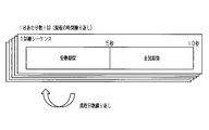
- one rehabilitation exercise (hereinafter referred to as “training sequence”) includes a rest period and an intention period during which an exercise intention is expressed.
- the rest period the patient is required to relax and not recall specific thoughts.
- the planning period the patient is required to express an exercise plan.
- the planning period may be referred to as an exercise planning period.
- the length of the rest period and the planning period is set, for example, to 5 seconds each.
- training progresses by alternately performing rest periods and exercise planning periods. For example, a training time of about 40 minutes is set per day, and the control device 50 repeats the training sequence a plurality of times. In other words, the training sequence is executed until the predetermined training time per day ends. For one patient, this training is performed for 10 days, for example, as a rehabilitation training.
- the training timing control unit 54 shown in FIG. 2 transmits the switching timing between the rest period and the exercise planning period to the presentation control unit 57.
- the presentation control unit 57 presents the timing to the patient via the image display unit 22 and the speaker 21.
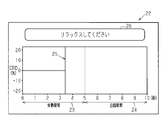
- FIG. 4 shows an example of information displayed on the image display unit 22.
- a rest period frame 23 indicating a rest period and an intention period frame 24 indicating an intention period are displayed side by side on the same time axis.
- the passage of time is displayed by vertical lines 25 that move from left to right with time.
- the request contents for the patient are also displayed in the message box 26.
- the message box 26 displays a message such as “Please relax” during the rest period.
- the message box 26 displays a message such as “Please plan your exercise” during the planning period.
- the image display unit 22 displays a message such as “Please plan your exercise” in the message box 26 when the rest period is switched to the planning period.
- the time when the vertical line 25 reaches the planning period frame 24 indicates the time when the rest period is switched to the planning period.
- the image display unit 22 is configured to visually output a motion recall request that requests the patient to start and / or continue a predetermined motion recall.
- the speaker 21 in the presentation device 20 shown in FIG. 1 may present different notification sounds at the start timing of the rest period and the start timing of the planning period. In this case, the patient can audibly recognize the switching between the rest period and the planning period. As described above, the speaker 21 is configured to acoustically output an exercise intention request that requests the patient to start and / or continue a predetermined exercise recall.
- the electroencephalogram reception unit 51 receives an electroencephalogram from the electroencephalogram transmission unit 13. At the same time, the brain wave training timing from the training timing control unit 54 is received.
- the electroencephalogram measurement apparatus 10 always measures an electroencephalogram and transmits an electroencephalogram signal during the training period.
- the electroencephalogram reception unit 51 can extract the electroencephalogram during the rest period and the electroencephalogram during the planning period from the electroencephalogram signal based on the training timing.
- the ERD detection unit 52 detects an ERD signal that is a signal related to the exercise plan from the brain wave during the rest period and the brain wave during the planning period.
- the ERD is an electroencephalogram that changes due to the expression of the exercise intention, and is uniquely generated when the exercise intention is expressed.
- the ERD signal is not detected during the rest period, and the ERD signal is detected only during the intention period. For example, based on the generation timing of the ERD signal and the training timing, it can be determined whether or not the exercise plan has been correctly expressed.
- the ERD signal is obtained by the time change of the frequency power of the electroencephalogram. In a predetermined time range, if a change in frequency power at a specific frequency, for example, around 10 Hz, is continuously observed for a predetermined time, it is determined that an ERD signal has been detected.
- feedback information for the patient is created by the feedback control unit 55.
- the feedback information is displayed on the screen of the image display unit 22 via the presentation control unit 57 (for example, the band 27 in FIG. 5) or is acoustically output from the speaker 21.
- the detection rate calculation unit 53 calculates the ERD detection rate based on the number of executed training sequences and the number of ERD signal detections.
- the training content of the electric appliance 30 is determined based on the ERD detection rate calculated by the detection rate calculation unit 53. Specifically, when the ERD detection rate obtained by the detection rate calculation unit 53 is lower than the threshold value, the motor control unit 58 and the muscle stimulation control unit 59 are not controlled via the appliance control unit 56, and the ERD is not performed. Only when the detection rate is higher than the threshold value, the control of the motor control unit 58 and the muscle stimulation control unit 59 via the appliance control unit 56 is executed based on the detection result of the ERD detection unit 52.
- the control device 50 starts training control by operating the operation unit 40.
- the training timing control unit 54 sends an instruction to the presentation control unit 57 so that the training sequence of the rest period and the planning period can be repeatedly presented.
- the presentation control unit 57 causes the image display unit 22 to display that training is being performed using a graph or the like.
- the presentation control unit 57 creates presentation information and causes the speaker 21 to present a notification sound.
- the patient recognizes that it has shifted to the planning period from at least one of the notification sound from the speaker 21 and the display content of the image display unit 22, and expresses the exercise plan.
- the calculation result 28 of the ERD attenuation rate is continuously displayed by the graph, and the ERD is detected when the ERD attenuation rate is not less than a certain value.
- the time interval is additionally displayed on the image display unit 22 as visual feedback information such as the band 27, for example. Further, the auditory feedback information that the ERD has been detected is notified.
- the visual feedback information from the image display unit 22 and the auditory feedback information from the speaker 21 may be referred to as feedback not via the electric appliance 30, that is, non-somatosensory feedback.
- the electric brace 30 When ERD is detected, the electric brace 30 provides somatosensory feedback to the patient. Whether or not this somatic sensory feedback is actually given is determined by the determination of the detection rate calculation unit 53 and the appliance control unit 56.
- one training sequence is started in a state where the patient pinches the peg P on the finger on which the electric appliance 30 is mounted. For this reason, when the ERD signal is detected, the finger is extended by the control of the motor 32 of the electric appliance 30 and the peg P falls. At this time, feedback from the muscle is given to the nerve function related to finger extension, and recovery of the nerve function is promoted. Further, as the electric appliance 30 is driven, the muscle stimulation electrode 33 applies electrical stimulation to muscles related to finger extension, for example, the total finger extensor muscles. For this reason, feedback from the muscle is given to the nerve function related to finger extension, and the recovery of the nerve function is promoted.
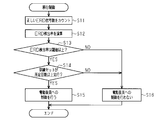
- step S11 the ERD detection unit 52 counts the number of correct exercise plans, that is, the number of correctly detected ERD signals, from the already executed training sequence. Specifically, when the ERD is not detected in the rest period of one training sequence and the ERD signal is detected in the planning period, the number of detections of the correct ERD signal is “1”.
- the ERD detection unit 52 calculates the ERD detection rate using the correct ERD signal counted in step S11 in step S12.
- the detection rate calculation unit 53 calculates the number of detections of the correct ERD signal with respect to the number of sequences executed in the same patient as the ERD detection rate.
- the feedback control unit 55 determines in step S13 whether or not the ERD detection rate is equal to or higher than a threshold value. When it is determined that the ERD detection rate is equal to or greater than the threshold, the feedback control unit 55 determines whether or not the training set has been executed a predetermined number of times or more in step S14. When it is determined that the training set has been executed a predetermined number of times or more, the feedback control unit 55 determines in step S15 that exercise planning has been sufficiently trained, and somatosensory feedback by the electric brace is effective, and motor control is performed. The activation control of the electric appliance 30 is performed via the unit 58 and the muscle stimulation control unit 59, and this process is terminated.
- the activation control of the electric appliance 30 is to turn on the motor 32 at the timing when the ERD signal is detected to extend the finger and simultaneously perform muscle stimulation from the muscle stimulation electrode 33.
- the electric appliance 30 may not be driven.
- step S13 when the feedback control unit 55 determines in step S13 that the ERD detection rate is less than the threshold value and in step S14, it is determined that the training set has not been executed a predetermined number of times or more, in step S16, the exercise attempt is performed. It is determined that there is a possibility that the somatosensory feedback by the electric brace 30 may hinder the exercise training, and this processing is performed without controlling the activation of the electric brace 30. finish.
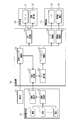
- the rehabilitation system 1 has the following operations and effects. (1) The difference between the rehabilitation system 1 of embodiment and the rehabilitation system of the reference example shown in FIG. 7 is demonstrated.
- the rehabilitation system of the reference example shown in FIG. 7 is different from the rehabilitation system 1 of the embodiment in that the detection rate calculation unit 53 and the appliance control unit 56 are not provided.
- the ERD detection unit 52 detects ERD
- the feedback control unit 55 directly controls the presentation device 20 and the electric appliance 30 as they are.
- all the feedback including somatosensory feedback by the electric appliance 30 is given in all cases where the ERD signal is detected even in the initial stage of training in which the ERD signal is likely to be erroneously determined. For this reason, when the detection of the ERD signal is determined without accompanying the exercise intention, there is a possibility that the exercise training for expressing the exercise intention may be confused.
- the control device 50 of the rehabilitation system 1 of the embodiment extracts an ERD signal related to the exercise plan from the electroencephalogram measured by the electroencephalogram measurement device 10, and determines that the exercise plan has been correctly expressed based on at least the ERD signal. It is sometimes configured to change the control of the electric appliance 30.
- the control device 50 switches feedback to the patient depending on whether the ERD detection rate is lower or higher than a predetermined value. That is, it can be said that the control device 50 provides two-stage feedback to the patient. For this reason, the control device 50 performs the first stage control in which the feedback by only the presentation device 20 is performed but the feedback by the electric appliance 30 is not performed in the initial stage of the training. Second stage control is performed in which feedback is provided by both of the appliances 30.
- this two-stage control corresponds to the rehabilitation training process.
- the expression of motor intentions is mainly targeted for training, and after that, the expression of motor plans can be expressed.
- the association is trained.
- control suitable for these two stages is possible.
- the control device 50 switches from the first stage control to the second stage control based on the ERD detection rate using the number of detections of the ERD signal.
- the training stage of the patient estimated to be able to appropriately express the exercise plan is automatically shifted to the second stage, so that the rehabilitation effect can be enhanced.
- the accuracy of the ERD detection rate is low in the early stages of training, and it is considered that more than a certain amount of training is necessary in order to be able to express exercise plans stably. For this reason, the control device 50 executes the first stage control until the ERD detection rate exceeds the threshold and the number of exercises reaches a predetermined number, the number of exercises reaches the predetermined number, and the exercise The process shifts to the second stage control based on the detection rate of the intentional expression exceeding the threshold. For this reason, it can be estimated more appropriately that the patient can appropriately express the exercise plan.
- the control device 50 shifts to the first stage control when the ERD detection rate falls below a threshold value that is a determination value. For this reason, after shifting to the second stage control, the first stage control is executed again when the patient is unable to successfully express the exercise plan again. For this reason, it is suppressed that the rehabilitation suitable for a patient's condition is performed.
- the rehabilitation system 1 of the present invention is not limited to the above embodiment, and may be modified as follows, for example. Several modifications may be combined as appropriate within the technically possible range.
- the ERD detection rate can also be calculated as in (A) or (B) below.
- (A) When the ERD signal is detected in the planning period of one training sequence, the control device 50 sets the number of times of detection of the correct ERD signal to “1” and stores the memory (not shown) in the ERD detection unit 52. To remember. And the control apparatus 50 calculates the total number of the detection frequency of the correct ERD signal with respect to the number of training sequences performed in the same patient as an ERD detection rate.
- the control device 50 determines the correct ERD signal.
- the number of detections is set to “1” and stored in a memory (not shown) inside the ERD detection unit 52.
- the control apparatus 50 calculates the total number of the detection frequency of the correct ERD signal with respect to twice the number of training sequences performed in the same patient as an ERD detection rate.
- the first training control can be shifted to the second training control.
- the control apparatus 50 can also display an ERD detection rate by the image display part 22, as shown in FIG. In this case, since the patient can grasp his / her ERD detection rate, the improvement of the rehabilitation effect can be expected. In addition, the ERD detection rate can be notified for each training set by the speaker 21.
- the threshold value used in step S13 of the transition control can be set to a different value when the first stage control is being executed and when the second stage control is being executed. For example, in step S13, when executing the first stage control, the control device 50 proceeds to step S16 when the ERD detection rate is less than the threshold value, and when executing the second stage control, the control apparatus 50 exceeds the threshold value. When the value falls below the large determination value, the process proceeds to step S16.
- the presentation device 20 can also indicate that the control device 50 shifts from the first step control to the second step control. In this case, the patient can recognize that the electric brace 30 is driven from the next training set.
- the electric appliance 30 can be driven.
- the driving amount of the electric brace 30, that is, the amount by which the limb is moved is made smaller than the driving amount in the second step control, thereby emphasizing the expression of the exercise plan rather than executing the second step control.
- the first stage only one of the muscle stimulation by the muscle stimulation electrode 33 and the passive movement by the motor 32 is executed.
- the second stage both the muscle stimulation by the muscle stimulation electrode 33 and the passive movement by the motor 32 are performed. It can also be executed.
- EEG reception unit 51, ERD detection unit 52, detection rate calculation unit 53, training timing control unit 54, feedback control unit 55, orthosis control unit 56, presentation control unit 57, motor control unit 58, and muscle stimulation control unit 59 May be hardware, and may be realized in software by the CPU executing a control program stored in the ROM.
- EEG reception unit 51, ERD detection unit 52, detection rate calculation unit 53, training timing control unit 54, feedback control unit 55, orthosis control unit 56, presentation control unit 57, motor control unit 58, and muscle stimulation control unit 59 May be realized by one processor which may be the control device 50, or may be realized by a plurality of processors included in the control device 50.
Landscapes
- Health & Medical Sciences (AREA)
- Life Sciences & Earth Sciences (AREA)
- Animal Behavior & Ethology (AREA)
- Veterinary Medicine (AREA)
- Public Health (AREA)
- General Health & Medical Sciences (AREA)
- Biophysics (AREA)
- Psychology (AREA)
- Biomedical Technology (AREA)
- Heart & Thoracic Surgery (AREA)
- Medical Informatics (AREA)
- Molecular Biology (AREA)
- Surgery (AREA)
- Pathology (AREA)
- Physics & Mathematics (AREA)
- Engineering & Computer Science (AREA)
- Psychiatry (AREA)
- Epidemiology (AREA)
- Pain & Pain Management (AREA)
- Physical Education & Sports Medicine (AREA)
- Rehabilitation Therapy (AREA)
- Rehabilitation Tools (AREA)
- Measurement And Recording Of Electrical Phenomena And Electrical Characteristics Of The Living Body (AREA)
Abstract
リハビリテーションシステムは、脳波測定装置10、提示装置20、電動装具30、および、制御装置50を備えている。脳波測定装置10は、測定結果を制御装置50に供給する。制御装置50は、提示装置20を介して、患者に情報を提示し、電動装具30を介して、電気的刺激および力学的刺激の少なくとも一方を患者に与えるように構成される。制御装置50は、脳波測定装置10によって計測された脳波から運動企図に関連したERD信号を抽出し、少なくともそのERD信号に基づいて運動企図に伴う運動野の活性化が生じたと判定したときに電動装具30の制御を変更する。
Description
本発明は、脳波に基づいて患者に刺激を与えるリハビリテーションシステム、および、その制御方法に関する。
従来、脳卒中等により体肢に麻痺を生じた患者を回復させるために、脳波に基づいて体肢を動作させるリハビリテーションが知られている。このリハビリテーションにおいては、患者が体肢を動作させようとする運動企図の表出を示す脳波の変化、例えば、事象関連脱同期(event-related desynchronization;ERD)に合わせて身体駆動装置が体肢を動作させることにより、リハビリテーションの効果が高まることが知られている(例えば、非特許文献1)。
特許文献1のリハビリテーションシステムは、脳波測定装置、患者の体肢を動作させる身体駆動装置、および、制御装置を備えている。制御装置は、運動企図の表出を示すERDを脳波測定装置によって検出し、検出されたERDに基づいて身体駆動装置を駆動させる。
Shindo K, Kawashima K, Ushiba J, Ota N, Ito M, Ota T, Kimura A, Liu M,"Effects of Neurofeedback training with an electroencephalogram-based brain-computer interface for hand paralysis in patients with chronic stroke: a case series study", Journal of Rehabilitation Medicine 2011, Vol.43, pp951-957
特許文献1に示される脳波に基づくリハビリテーション方法では、患者は運動企図を適切に表出する必要がある。しかしながら、患者がリハビリテーションになれていないリハビリテーションの初期においては、患者が適切に運動企図を表出できないことがあり、運動企図の表出のための訓練を患者に提供しなければならない。運動企図の表出が正しく行えない状況では、脳波が頻繁に変化し、ERDがしばしば誤検出されて、そのたびに身体駆動装置が誤って駆動される。このため、身体駆動装置の誤動作は患者にとって煩わしく、リハビリテーションの効果を低下させるおそれがある。
本発明の目的は、リハビリテーションの効果を高めることができるリハビリテーションシステムおよびリハビリテーションシステムの制御方法を提供することである。
本発明の一側面に従うリハビリテーションシステムは、脳波測定装置と、患者に対してフィードバック情報を含む情報を提示するように構成される情報提示装置と、患者に装着されて、電気的刺激および力学的刺激の少なくとも一方を患者に与えるように構成される電動装具と、前記脳波測定装置によって計測された脳波から運動企図に関連した信号を抽出し、少なくともその信号に基づいて運動企図が正しく表出できたと判断したときに前記電動装具の制御を変更するように構成される制御装置を備える。
本発明の一側面に従うリハビリテーションシステムは、脳波測定装置と、患者に対してフィードバック情報を含む情報を提示するように構成される情報提示装置と、患者に装着されて、電気的刺激および力学的刺激の少なくとも一方を患者に与えるように構成される電動装具と、前記脳波測定装置によって計測された脳波から運動企図に関連した信号を抽出し、少なくともその信号に基づいて運動企図が正しく表出できたと判断したときに前記電動装具の制御を変更するように構成される制御装置を備える。
本発明の一側面によれば、リハビリテーションの効果を高めることができるリハビリテーションシステムを提供することができる。本発明の他の側面及び利点は本発明の技術的思想の例を示す図面と共に以下の記載から明らかとなる。
以下、運動療法によるリハビリテーションの際に、脳波解析に基づいて、随意運動を補助するために用いられるリハビリテーションシステム、および、リハビリテーションシステムの制御方法について説明する。
図1に示されるように、実施形態に従うリハビリテーションシステム1は、脳波測定装置10、情報提示装置20、電動装具30、操作部40、および、制御装置50を備えている。
脳波測定装置10は、患者の頭への装着に適するヘッドホン形状を有することができ、複数の電極11、脳波計測部12、および、脳波送信部13を備えている。
複数の電極11は、患者が脳波測定装置10を頭部に装着したときに、患者の運動企図に関連する脳波の測定に適した位置に配置されるように、例えばアーチ形の弾性ヘッドマウントによって支持される。複数の電極11は、例えば、患者の右半身の随意運動を支配する左運動野、および、患者の左半身の随意運動を右運動野に対応できる位置(脳波電極の指定方法である国際10-20法におけるC4、C3の位置)に配置することが好ましい。電極11の配置を左運動野および右運動野のそれぞれと対応させることにより、同一のリハビリテーションシステム1を左半身の麻痺を有する患者および右半身の麻痺を有する患者の両方に用いることができる。なお、軽量化、簡易装着等の観点から、脳波測定装置10は、片側の運動野のみに対応する電極11を備えるいわゆるヘッドセット形状を有してもよい。
複数の電極11は、患者が脳波測定装置10を頭部に装着したときに、患者の運動企図に関連する脳波の測定に適した位置に配置されるように、例えばアーチ形の弾性ヘッドマウントによって支持される。複数の電極11は、例えば、患者の右半身の随意運動を支配する左運動野、および、患者の左半身の随意運動を右運動野に対応できる位置(脳波電極の指定方法である国際10-20法におけるC4、C3の位置)に配置することが好ましい。電極11の配置を左運動野および右運動野のそれぞれと対応させることにより、同一のリハビリテーションシステム1を左半身の麻痺を有する患者および右半身の麻痺を有する患者の両方に用いることができる。なお、軽量化、簡易装着等の観点から、脳波測定装置10は、片側の運動野のみに対応する電極11を備えるいわゆるヘッドセット形状を有してもよい。
脳波計測部12は、電極11のうちの2つの電極間の電位差を増幅して脳波を計測する。脳波送信部13は、脳波計測部12にて計測された脳波を含む脳波信号を制御装置50の脳波受信部51に送信する。
情報提示装置20は、単に提示装置と呼ぶことがある。提示装置20は、音響的出力装置としてのスピーカー21および視覚的出力装置としての画像表示部22を備えている。スピーカー21は、制御装置50からの音響信号に基づいて、患者に音および音声を提示する。画像表示部22は、制御装置50からの制御信号に基づいて、患者に視覚情報を提示する。患者に提示される情報は、患者がどのようなリハビリテーション運動を企図すれば良いかの指示に関する指示情報と、患者が指示通りに企図できているかのフィードバック情報とを含む。
電動装具30は、患者の指および腕に装着される装具31、モータ32、および、筋刺激電極33を備えている。モータ32は、装具31の肘付近に取り付けられている。モータ32の出力軸と装具31の指の背の部分とは、図示しないワイヤーにより接続されている。モータ32が回転することにより、装具31を装着した患者の指がワイヤーにより引っ張られ、指に力学的な刺激が与えられ、患者の指が他動的に運動させられる。
筋刺激電極33は、患者の前腕部に筋刺激を与えるように構成される。筋刺激電極33は、ERD検出のタイミングに基づいて制御される制御装置50の筋刺激制御部59(図2参照)による電極33間の電流制御によって患者の前腕部に電気的な刺激を与える。この電気的な刺激が患者の前腕部の筋刺激となる。筋刺激およびモータ32の制御にともなう他動的な運動は、患者への体性感覚フィードバックとなる。
操作部40は、例えば、マウスやタッチパネル等として構成される。リハビリテーションの補助者、例えば作業療法士は、操作部40を介して患者に関する各種情報を制御装置50に登録したり、制御装置50に対する訓練の開始や停止の指示を入力したりする。操作部40がタッチパネルとして構成される場合には、提示装置20に一体化することもできる。
図2を参照して、制御装置50について説明する。制御装置50は、脳波受信部51、ERD検出部52、検出率演算部53、訓練タイミング制御部54、フィードバック制御部55、装具制御部56、提示制御部57、モータ制御部58、および、筋刺激制御部59を備えている。制御装置50は、電子回路を含むいわゆるマイクロコンピューターであり得る。制御装置50は、各種制御プログラムが格納されたROM(Read Only Memory)及びROMにアクセス可能なCPU(Central Processing Unit)を含むことができる。
制御装置50は、操作部40からの操作と、提示装置20、電動装具30への制御とによって、安静状態と運動企図の表出とを交互に所定の時間間隔で行う訓練を患者に実行させる。
リハビリテーションの訓練は、操作部40からの開始指示によって開始される。作業療法士の操作により操作部40から開始指示が訓練タイミング制御部54に入力され、一連の訓練のプロセスが実行される。
図3に示すように、リハビリテーションの1回の訓練(以下、「訓練シーケンス」)は安静期間と運動企図の表出を行う企図期間とを含んで構成される。安静期間では、患者はリラックスして特定の思考を想起しないことが求められる。一方、企図期間では、患者は運動企図を表出することが求められる。企図期間は、運動企図期間と呼ぶことがある。安静期間および企図期間の長さは、例えば、各5秒間に設定される。
そして、安静期間と運動企図期間を交互に行うことで訓練が進行する。1日あたり、例えば40分程度の訓練時間が設定され、その中で制御装置50は、上記訓練シーケンスを複数回繰り返す。換言すれば、1日あたり所定の訓練時間が終了するまで訓練シーケンスが実行される。患者1名に対しては、この訓練を例えば10日間にわたって実行することでリハビリテーションの訓練とする。
図2に示される訓練タイミング制御部54は、安静期間と運動企図期間との切り替えタイミングを提示制御部57に伝達する。提示制御部57は、患者に対して画像表示部22およびスピーカー21を介してそのタイミングを提示する。
図4に、画像表示部22に表示される情報の例を示す。画像表示部22には、安静期間を示す安静期間枠23と、企図期間を示す企図期間枠24とが同じ時間軸上に並べられて表示される。時間の経過は、時間とともに左から右に移動する縦線25によって表示される。また、患者に対する要請内容はメッセージボックス26にも表示される。メッセージボックス26は、安静期間には「リラックスしてください」等のメッセージを表示する。また、図5に示すように、メッセージボックス26は、企図期間には「運動を企図してください」等のメッセージを表示する。
画像表示部22は、安静期間から企図期間に切り替わった時点で、「運動を企図してください」等のメッセージをメッセージボックス26に表示する。また、縦線25が企図期間枠24に達した時点は、安静期間から企図期間に切り替わった時点を示す。このように、画像表示部22は、患者に所定の運動想起の開始及び/または継続を要求する運動想起リクエストを視覚的に出力するように構成されている。
また、図1に示す提示装置20内のスピーカー21は、安静期間の開始タイミングと、企図期間の開始タイミングとでは、異なる報知音を提示するようにしてもよい。この場合、患者は、安静期間と企図期間との切り替わりを聴覚的に認識できる。このように、スピーカー21は患者に所定の運動想起の開始及び/または継続を要求する運動企図リクエストを音響的に出力するように構成されている。
次に、図2を参照して、訓練中の運動企図の分析のための脳波解析と患者への解析結果のフィードバックについて説明する。
脳波受信部51は、脳波送信部13からの脳波を受信する。また、同時に訓練タイミング制御部54からの脳波訓練タイミングを受信する。脳波測定装置10は、訓練期間中には常に脳波を計測して脳波信号を送信している。脳波受信部51は、訓練タイミングに基づいて、脳波信号から安静期間の脳波と企図期間の脳波とを抽出することができる。
脳波受信部51は、脳波送信部13からの脳波を受信する。また、同時に訓練タイミング制御部54からの脳波訓練タイミングを受信する。脳波測定装置10は、訓練期間中には常に脳波を計測して脳波信号を送信している。脳波受信部51は、訓練タイミングに基づいて、脳波信号から安静期間の脳波と企図期間の脳波とを抽出することができる。
ERD検出部52は、安静期間の脳波と企図期間の脳波とから、運動企図に関連した信号であるERD信号を検出する。ERDは、運動企図の表出により変化する脳波であり、運動企図を表出しているときに特有に発生するとされる。患者が運動企図を正しく表出できている場合には、安静期間には、ERD信号は検出されず、企図期間にのみERD信号が検出される。例えば、ERD信号の発生タイミングと訓練タイミングとに基づいて、運動企図が正しく表出できたかどうかを判断することができる。
ERD信号は、脳波の周波数パワーの時間変化によって求められる。所定の時間範囲において、特定の周波数、例えば10Hz付近の周波数パワーの変化が、所定の時間継続して見られた場合には、ERD信号が検出されたと判定される。
ERD信号が検出されたと判定された場合には、フィードバック制御部55によって患者に対するフィードバック情報が作成される。フィードバック情報は提示制御部57を経由して、画像表示部22の画面上に表示されたり(例えば図5の帯27)、スピーカー21から音響的に出力されたりする。
検出率演算部53は、実行された訓練シーケンス数とERD信号の検出回数とに基づいてERD検出率を演算する。検出率演算部53により演算されたERD検出率に基づいて電動装具30の訓練内容を決定する。具体的には、検出率演算部53にて求められたERD検出率が閾値より低い場合には、装具制御部56を介したモータ制御部58および筋刺激制御部59の制御が行われず、ERD検出率が閾値より高い場合にのみ、ERD検出部52の検出結果に基づいて、装具制御部56を介したモータ制御部58および筋刺激制御部59の制御が実行される。
以下、図1、図4および図5を参照して、訓練中の動作について説明する。
制御装置50は、操作部40の操作により訓練制御を開始する。訓練タイミング制御部54は、安静期間と企図期間との訓練シーケンスを繰り返し提示できるように、提示制御部57に指示を送る。提示制御部57は、図4および図5に示されるように訓練の実行中である旨をグラフ等により画像表示部22に表示させる。安静期間の開始時と、企図期間の開始時には提示制御部57に提示情報を作成させ、スピーカー21に報知音を提示させる。
制御装置50は、操作部40の操作により訓練制御を開始する。訓練タイミング制御部54は、安静期間と企図期間との訓練シーケンスを繰り返し提示できるように、提示制御部57に指示を送る。提示制御部57は、図4および図5に示されるように訓練の実行中である旨をグラフ等により画像表示部22に表示させる。安静期間の開始時と、企図期間の開始時には提示制御部57に提示情報を作成させ、スピーカー21に報知音を提示させる。
患者は、スピーカー21からの報知音、および、画像表示部22の表示内容の少なくとも一方から企図期間に移行した旨を認識し、運動企図の表出を行う。安静期間および企図期間においては、図5に示されるように、ERDの減衰率の計算結果28がグラフによって連続的に表示され、そのERDの減衰率が一定以上の場合に、ERDが検出されたと判定し、その時間区間は例えば帯27のような視覚フィードバック情報として画像表示部22に追加的に表示される。また、聴覚フィードバック情報として、スピーカー21からERDが検出された旨が報知される。画像表示部22からの視覚フィードバック情報及びスピーカー21からの聴覚フィードバック情報は、電動装具30を介さないフィードバックすなわち非体性感覚フィードバックと呼ぶことがある。
ERDが検出された場合には、電動装具30が体性感覚フィードバックを患者に提供する。この体性感覚フィードバックを実際に与えるかどうかは、検出率演算部53および装具制御部56の判定によって決定される。
図1に示されるように、1訓練シーケンスは、患者が電動装具30の装着された指にペグPをつまんだ状態において開始される。このため、ERD信号が検出されたとき、電動装具30のモータ32の制御により、指が伸展し、ペグPが落ちる。このとき、指の伸展に関わる神経機能に筋肉からフィードバックが付与され、神経機能の回復が促される。また、電動装具30の駆動とともに、筋刺激電極33により、指の伸展に関わる筋肉、例えば、総指伸筋に電気刺激が付与される。このため、指の伸展に関わる神経機能に筋肉からのフィードバックが付与され、神経機能の回復が促される。
図6を参照して、検出率演算部53および装具制御部56の処理手順を中心に説明する。この処理は、適切なフィードバックを与えるために、ERD検出部52の処理が終了した後に、毎回実施される。
ERD検出部52は、ステップS11において、既に実行された訓練シーケンスの中から、正しい運動企図の表出、すなわち、正しくERD信号が検出された数をカウントする。具体的には、1訓練シーケンスのうちの安静期間においてERDが検出されず、かつ、企図期間においてERD信号が検出されたとき、正しいERD信号の検出の回数を「1」とする。
次に、ERD検出部52は、ステップS12においてステップS11においてカウントした正しいERD信号を用いてERD検出率を演算する。検出率演算部53は、同一の患者において実行されたシーケンス数に対する正しいERD信号の検出回数をERD検出率として演算する。
次に、フィードバック制御部55は、ステップS13においてERD検出率が閾値以上か否かを判定する。フィードバック制御部55は、ERD検出率が閾値以上である旨判定したとき、ステップS14において訓練セットが所定回数以上実行されたか否かを判定する。フィードバック制御部55は、訓練セットが所定回数以上実行された旨判定したとき、ステップS15において運動企図の訓練が十分なされており、電動装具による体性感覚フィードバックが有効であると判定し、モータ制御部58および筋刺激制御部59を経由して電動装具30の活性化制御を行い、本処理を終了する。
具体的には電動装具30の活性化制御とは、ERD信号が検出されたタイミングでモータ32をオンして指の伸展をさせ、同時に筋刺激電極33から筋刺激を行うことである。ERD信号が検出されない場合には、電動装具30は駆動しなくてよい。
他方、フィードバック制御部55は、ステップS13においてERD検出率が閾値未満である旨判定したとき、および、ステップS14において訓練セットが所定回数以上実行されていない旨判定したとき、ステップS16において、運動企図の訓練が十分になされておらず、電動装具30による体性感覚フィードバックは運動企図の訓練の妨げになる可能性があると判定し、電動装具30の活性化制御を行わずに、本処理を終了する。
リハビリテーションシステム1は、以下の作用および効果を奏する。
(1)実施形態のリハビリテーションシステム1と図7に示す参考例のリハビリテーションシステムとの違いについて説明する。図7に示す参考例のリハビリテーションシステムは、検出率演算部53および装具制御部56を備えていない点において実施形態のリハビリテーションシステム1とは相違している。参考例のリハビリテーションシステムでは、ERD検出部52にてERDが検出された場合、そのままフィードバック制御部55から、提示装置20および電動装具30に対する制御が自動的に行われている。この場合には、ERD信号が誤って判定されやすい訓練初期の段階においても、ERD信号が検出されたすべての場合に、電動装具30による体性感覚フィードバックを含めたすべてのフィードバックが与えられる。このため、運動企図を伴わずにERD信号の検出が判定された場合に、運動企図の表出の訓練が混乱させられるおそれがある。
(1)実施形態のリハビリテーションシステム1と図7に示す参考例のリハビリテーションシステムとの違いについて説明する。図7に示す参考例のリハビリテーションシステムは、検出率演算部53および装具制御部56を備えていない点において実施形態のリハビリテーションシステム1とは相違している。参考例のリハビリテーションシステムでは、ERD検出部52にてERDが検出された場合、そのままフィードバック制御部55から、提示装置20および電動装具30に対する制御が自動的に行われている。この場合には、ERD信号が誤って判定されやすい訓練初期の段階においても、ERD信号が検出されたすべての場合に、電動装具30による体性感覚フィードバックを含めたすべてのフィードバックが与えられる。このため、運動企図を伴わずにERD信号の検出が判定された場合に、運動企図の表出の訓練が混乱させられるおそれがある。
実施形態のリハビリテーションシステム1の制御装置50は、脳波測定装置10によって計測された脳波から運動企図に関連したERD信号を抽出し、少なくともそのERD信号に基づいて運動企図が正しく表出できたと判定したときに電動装具30の制御を変更するように構成される。
このため、運動企図の表出の訓練と、運動企図の表出と体性感覚の関係性の学習のそれぞれに集中することができる。このため、特にリハビリテーションの初期において、患者がERDの表出を適切に行えるように訓練しやすくなり、リハビリテーションの効果を高めることができる。
(2)制御装置50は、ERD検出率が所定の値より低い場合と高い場合とで、患者へのフィードバックを切り替えている。すなわち、制御装置50は、患者に対しては2段階のフィードバックを与えていると言える。このため、制御装置50は、訓練初期には提示装置20のみによるフィードバックを行うが電動装具30によるフィードバックを行わない第1段階制御を実施し、訓練が進んできた後には、提示装置20、電動装具30の両方によるフィードバックを行う第2段階制御を実施する。
この2段階の制御は、リハビリテーションの訓練過程に対応した制御であると言える。すなわちリハビリテーション初期には、運動企図の表出が主に訓練対象となり、その後運動企図の表出ができるようになってからは、運動企図と、実際の他動的運動に伴う体性感覚フィードバックとの関連付けが訓練される。リハビリテーションシステム1では、この2段階に適した制御が可能になる。
(3)制御装置50は、ERD信号の検出回数を用いたERD検出率に基づいて、第1段階制御から第2段階制御に切り替えている。この場合、運動企図を適切に表出できるようになったと推定される患者の訓練段階が自動的に第2段階に移行されるため、リハビリテーションの効果を高めることができる。
(4)一般的に訓練初期にはERD検出率の精度が低く、安定して運動企図の表出ができるようになるには、一定以上の訓練が必要と考えられる。このため、制御装置50は、ERD検出率が閾値を超えるまで、かつ、訓練の回数が所定の回数に達するまで第1段階制御を実行し、訓練の回数が所定の回数に達し、かつ、運動企図の表出の検出率が閾値を超えたことに基づいて第2段階制御に移行する。このため、患者が運動企図を適切に表出できるようになった旨をより適切に推定できる。
(5)制御装置50は、第2段階制御を実行しているときに、ERD検出率が判定値である閾値を下回ったとき、第1段階制御に移行する。このため、第2段階制御に移行した後に、患者が再び運動企図の表出を上手くおこなえなくなったときに再び第1段階制御が実行される。このため、患者の状態に適しないリハビリテーションが行われることが抑制される。
本発明のリハビリテーションシステム1は、上記実施形態に限定されず、例えば以下のように変形してもよい。技術的に可能な範囲においていくつかの変形例を適宜組み合わせてもよい。
・ERD検出率を、以下の(A)または(B)のように演算することもできる。
(A)制御装置50は、1訓練シーケンスのうちの企図期間においてERD信号が検出されたとき、正しいERD信号の検出の回数を「1」として、ERD検出部52内部のメモリー(図示せず)に記憶する。そして、制御装置50は、同一の患者において実行された訓練シーケンス数に対する正しいERD信号の検出の回数の総数をERD検出率として演算する。
(A)制御装置50は、1訓練シーケンスのうちの企図期間においてERD信号が検出されたとき、正しいERD信号の検出の回数を「1」として、ERD検出部52内部のメモリー(図示せず)に記憶する。そして、制御装置50は、同一の患者において実行された訓練シーケンス数に対する正しいERD信号の検出の回数の総数をERD検出率として演算する。
(B)制御装置50は、1訓練シーケンスのうちの安静期間においてERD信号が検出されなかったとき、および、1訓練シーケンスのうちの企図期間においてERD信号が検出されたとき、それぞれ正しいERD信号の検出の回数を「1」として、ERD検出部52内部のメモリー(図示せず)に記憶する。そして、制御装置50は、同一の患者において実行された訓練シーケンス数の2倍に対する正しいERD信号の検出の回数の総数をERD検出率として演算する。
・正しいERD検出の回数の総数が所定の値を超えたとき、第1訓練制御から第2訓練制御に移行させることもできる。
・制御装置50は、図8に示すようにERD検出率を画像表示部22により表示させることもできる。この場合、患者が自身のERD検出率を把握できるため、リハビリテーションの効果の向上を見込むことができる。また、スピーカー21により訓練セットごとにERD検出率を報知させることもできる。
・制御装置50は、図8に示すようにERD検出率を画像表示部22により表示させることもできる。この場合、患者が自身のERD検出率を把握できるため、リハビリテーションの効果の向上を見込むことができる。また、スピーカー21により訓練セットごとにERD検出率を報知させることもできる。
・移行制御のステップS13において用いられる閾値を、第1段階制御を実行しているときと第2段階制御を実行しているときとで異なる値に設定することもできる。例えば、ステップS13において、制御装置50は、第1段階制御を実行しているとき、ERD検出率が閾値未満のとき、ステップS16に進み、第2段階制御を実行しているとき、閾値よりも大きい判定値を下回ったとき、ステップS16に進むようにする。
・移行制御において、第1段階制御から第2段階制御に移行した後は、第1段階制御に移行しないようにすることもできる。
・制御装置50は、第1段階制御から第2段階制御に移行するとき、第1段階制御から第2段階制御に移行する旨を提示装置20により提示することもできる。この場合、患者は、次の訓練のセットから電動装具30が駆動することを認識できる。
・制御装置50は、第1段階制御から第2段階制御に移行するとき、第1段階制御から第2段階制御に移行する旨を提示装置20により提示することもできる。この場合、患者は、次の訓練のセットから電動装具30が駆動することを認識できる。
・第1段階制御において、電動装具30を駆動するようにすることもできる。この場合、電動装具30の駆動量、すなわち、体肢を動作させる量を第2段階制御における駆動量よりも小さくすることにより、第2段階制御を実行するときよりも運動企図の表出に重点をおいた訓練を行わせることができる。また、第1段階において、筋刺激電極33による筋刺激およびモータ32による他動運動の一方のみを実行させ、第2段階において、筋刺激電極33による筋刺激およびモータ32による他動運動の両方を実行させることもできる。
なお、第1段階制御と第2段階制御とを操作部40により強制的に変更させる構成を追加することもできる。
・電動装具30からモータ32および筋刺激電極33の一方を省略することもできる。
・電動装具30からモータ32および筋刺激電極33の一方を省略することもできる。
・電動装具30は患者の下肢に装着する形状にすることもできる。
・脳波受信部51、ERD検出部52、検出率演算部53、訓練タイミング制御部54、フィードバック制御部55、装具制御部56、提示制御部57、モータ制御部58、および、筋刺激制御部59は、ハードウェアであってもよく、CPUがROMに記憶された制御プログラムを実行することによってソフトウェア的に実現されてもよい。
・脳波受信部51、ERD検出部52、検出率演算部53、訓練タイミング制御部54、フィードバック制御部55、装具制御部56、提示制御部57、モータ制御部58、および、筋刺激制御部59は、ハードウェアであってもよく、CPUがROMに記憶された制御プログラムを実行することによってソフトウェア的に実現されてもよい。
・脳波受信部51、ERD検出部52、検出率演算部53、訓練タイミング制御部54、フィードバック制御部55、装具制御部56、提示制御部57、モータ制御部58、および、筋刺激制御部59は、制御装置50であり得る一つのプロセッサによって実現されてもよく、制御装置50に含まれる複数のプロセッサによって実現されてもよい。
本発明は、例示したものに限定されるものではない。例えば、例示した特徴が本発明にとって必須であると解釈されるべきでなく、本発明の主題は、開示した特定の実施形態の全ての特徴より少ない特徴に存在することがある。
1…リハビリテーションシステム、10…脳波測定装置、20…提示装置、30…電動装具、40…操作部、50…制御装置。
Claims (11)
- 脳波測定装置と、
患者に対してフィードバック情報を含む情報を提示するように構成される情報提示装置と、
患者に装着されて、電気的刺激および力学的刺激の少なくとも一方を患者に与えるように構成される電動装具と、
前記脳波測定装置によって計測された脳波から運動企図に関連した信号を抽出し、少なくともその信号に基づいて運動企図が正しく表出できたと判定したときに前記電動装具の制御を変更するように構成される制御装置と
を備えるリハビリテーションシステム。 - 前記制御装置は、
前記運動企図が正しく表出されたときに前記運動企図が正しく表出されたことを前記情報提示装置により患者に提示し、かつ、前記電動装具を駆動させない第1段階制御と、
前記運動企図が正しく表出されたときに前記電動装具を駆動させる第2段階制御と、を実行するように構成される請求項1に記載のリハビリテーションシステム。 - 前記制御装置は、前記運動企図が正しく表出された回数に基づいて、前記第1段階制御から前記第2段階制御に切り替えるように構成される請求項2に記載のリハビリテーションシステム。
- 前記制御装置は、訓練の回数に対する前記運動企図が正しく表出された回数である前記運動企図の検出率が閾値を超えるまで前記第1段階制御を実行し、前記運動企図の検出率が前記閾値を超えたことに基づいて、前記第2段階制御に移行するように構成される請求項3に記載のリハビリテーションシステム。
- 前記制御装置は、
前記運動企図の検出率が前記閾値を超えるまで、かつ、前記訓練の回数が所定の回数に達するまで前記第1段階制御を実行し、
前記訓練の回数が所定の回数に達し、かつ、前記運動企図の検出率が前記閾値を超えたことに基づいて前記第2段階制御に移行するように構成される請求項4に記載のリハビリテーションシステム。 - 前記制御装置は、前記第2段階制御を実行しているときに、前記運動企図の検出率が判定値を下回ったとき、前記第1段階制御に移行するように構成される請求項4または5に記載のリハビリテーションシステム。
- 前記制御装置は、前記運動企図の検出率を前記情報提示装置により患者に提示させるように構成される請求項4~6のいずれか一項に記載のリハビリテーションシステム。
- 前記制御装置は、前記運動企図の検出率に基づいてリハビリテーションのスケジュールを決定するように構成される請求項4~7のいずれか一項に記載のリハビリテーションシステム。
- 前記制御装置は、前記第1段階制御から前記第2段階制御に移行するとき、前記第1段階制御から前記第2段階制御に移行する旨を前記情報提示装置により患者に提示するように構成される請求項2~8のいずれか一項に記載のリハビリテーションシステム。
- 前記電動装具によって生成される前記電気的刺激および前記力学的刺激の少なくとも一方は、体性感覚フィードバックであり、
前記情報提示装置によって提示される前記フィードバック情報は、非体性感覚フィードバックであり、
前記制御装置は、
患者に所定のリハビリテーション運動の想起を要求する運動想起リクエストを、前記情報提示装置から視覚的及び/または音響的に出力し、
前記運動想起リクエストの出力前の脳波と、前記運動想起リクエストの出力後の脳波とに少なくとも基づいて、前記リハビリテーション運動の想起に対する前記患者の訓練の程度を判定し、
その判定結果に応じて、
前記情報提示装置による前記非体性感覚フィードバックの単独実行、及び
前記電動装具による前記体性感覚フィードバックと前記情報提示装置による前記非体性感覚フィードバックとの同時実行と
を少なくとも含む複数のフィードバックモードのうちの一つを選択的に実行するように構成される、請求項1~9のいずれか一項に記載のリハビリテーションシステム。 - 前記脳波測定装置が脳波を計測し、
前記脳波から抽出される、運動企図に関連した信号に少なくとも基づいて、前記運動企図が正しく表出できたと判定したときに、前記制御装置が前記電動装具の制御を変更すること、
を備える請求項1~10のいずれか一項に記載のリハビリテーションシステムの制御方法。
Applications Claiming Priority (2)
| Application Number | Priority Date | Filing Date | Title |
|---|---|---|---|
| JP2014135354A JP6536869B2 (ja) | 2014-06-30 | 2014-06-30 | リハビリテーションシステムおよびリハビリテーションシステムの制御方法 |
| JP2014-135354 | 2014-06-30 |
Publications (1)
| Publication Number | Publication Date |
|---|---|
| WO2016002200A1 true WO2016002200A1 (ja) | 2016-01-07 |
Family
ID=55018777
Family Applications (1)
| Application Number | Title | Priority Date | Filing Date |
|---|---|---|---|
| PCT/JP2015/003272 Ceased WO2016002200A1 (ja) | 2014-06-30 | 2015-06-30 | リハビリテーションシステムおよびリハビリテーションシステムの制御方法 |
Country Status (2)
| Country | Link |
|---|---|
| JP (1) | JP6536869B2 (ja) |
| WO (1) | WO2016002200A1 (ja) |
Cited By (2)
| Publication number | Priority date | Publication date | Assignee | Title |
|---|---|---|---|---|
| US10937333B2 (en) | 2016-10-19 | 2021-03-02 | Seiko Epson Corporation | Rehabilitation system |
| CN117695129A (zh) * | 2023-12-15 | 2024-03-15 | 中航创世机器人(西安)有限公司 | 手部康复训练设备的智能控制方法 |
Families Citing this family (1)
| Publication number | Priority date | Publication date | Assignee | Title |
|---|---|---|---|---|
| JP6905500B2 (ja) * | 2017-10-20 | 2021-07-21 | パナソニック株式会社 | リハビリテーション支援システム、リハビリテーション支援システムの制御方法、及びプログラム |
Citations (4)
| Publication number | Priority date | Publication date | Assignee | Title |
|---|---|---|---|---|
| JP2006296468A (ja) * | 2005-04-15 | 2006-11-02 | National Institute Of Advanced Industrial & Technology | 体性感覚運動統合評価訓練システム |
| JP2008510560A (ja) * | 2004-08-25 | 2008-04-10 | モトリカ リミテッド | 脳の可塑性による運動訓練 |
| JP2011186667A (ja) * | 2010-03-05 | 2011-09-22 | Osaka Univ | 機器制御装置、機器システム、機器制御方法、機器制御プログラム、および記録媒体 |
| JP2012217721A (ja) * | 2011-04-12 | 2012-11-12 | Keio Gijuku | リハビリテーション用脳波信号処理装置、それを備えるリハビリテーションシステム、及び、それに用いられる電極パッド |
-
2014
- 2014-06-30 JP JP2014135354A patent/JP6536869B2/ja active Active
-
2015
- 2015-06-30 WO PCT/JP2015/003272 patent/WO2016002200A1/ja not_active Ceased
Patent Citations (4)
| Publication number | Priority date | Publication date | Assignee | Title |
|---|---|---|---|---|
| JP2008510560A (ja) * | 2004-08-25 | 2008-04-10 | モトリカ リミテッド | 脳の可塑性による運動訓練 |
| JP2006296468A (ja) * | 2005-04-15 | 2006-11-02 | National Institute Of Advanced Industrial & Technology | 体性感覚運動統合評価訓練システム |
| JP2011186667A (ja) * | 2010-03-05 | 2011-09-22 | Osaka Univ | 機器制御装置、機器システム、機器制御方法、機器制御プログラム、および記録媒体 |
| JP2012217721A (ja) * | 2011-04-12 | 2012-11-12 | Keio Gijuku | リハビリテーション用脳波信号処理装置、それを備えるリハビリテーションシステム、及び、それに用いられる電極パッド |
Cited By (2)
| Publication number | Priority date | Publication date | Assignee | Title |
|---|---|---|---|---|
| US10937333B2 (en) | 2016-10-19 | 2021-03-02 | Seiko Epson Corporation | Rehabilitation system |
| CN117695129A (zh) * | 2023-12-15 | 2024-03-15 | 中航创世机器人(西安)有限公司 | 手部康复训练设备的智能控制方法 |
Also Published As
| Publication number | Publication date |
|---|---|
| JP6536869B2 (ja) | 2019-07-03 |
| JP2016013181A (ja) | 2016-01-28 |
Similar Documents
| Publication | Publication Date | Title |
|---|---|---|
| WO2016002207A1 (ja) | リハビリテーションシステムおよびリハビリテーションシステムの制御方法 | |
| US20220338761A1 (en) | Remote Training and Practicing Apparatus and System for Upper-Limb Rehabilitation | |
| CN103764021B (zh) | 一种用于协同神经-生理学修复和/或功能提升的系统、仪器、装置和方法 | |
| US10762988B2 (en) | Motor training | |
| Elnady et al. | A single-session preliminary evaluation of an affordable BCI-controlled arm exoskeleton and motor-proprioception platform | |
| CN110337265A (zh) | 用于改善外周神经功能的方法和装置 | |
| AU2012259507A1 (en) | Systems, apparatuses, devices, and processes for synergistic neuro-physiological rehabilitation and/or functional development | |
| CN106413532A (zh) | 康复系统和方法 | |
| US20240082533A1 (en) | System for functional rehabilitation and/or pain rehabilitation due to sensorimotor impairment | |
| JP2017516571A (ja) | リハビリテーションシステム及び方法 | |
| Coffey et al. | A novel BCI-controlled pneumatic glove system for home-based neurorehabilitation | |
| JP7846929B2 (ja) | ウェアラブルデバイスを使用した神経学的運動障害の症状を軽減するためのデバイス及び方法 | |
| Ortiz-Catalan et al. | Virtual reality | |
| US11957475B2 (en) | Biometric information processing device, biometric information processing method and program | |
| KR102174257B1 (ko) | 뇌-컴퓨터 인터페이스 제어를 위한 실시간 피드백 시스템 및 방법 | |
| Guggenberger et al. | Brain-machine neurofeedback: robotics or electrical stimulation? | |
| JP6536869B2 (ja) | リハビリテーションシステムおよびリハビリテーションシステムの制御方法 | |
| JPWO2019078325A1 (ja) | 脳波判定システム、脳波判定方法、プログラム、及び非一時的記録媒体 | |
| Tanabe et al. | Illusory Directional Sensation Induced by Asymmetric Vibrations Influences Sense of Agency and Velocity in Wrist Motions | |
| SG10201800971RA (en) | Method and system for motor function rehabilitation and monitoring a patient’s recovery | |
| Imbeault-Nepton et al. | Synchronized walking cadence for TUG in perturbed environments: Using Earcon or Tacton cues? | |
| JP2020048975A (ja) | 脳波訓練システム、脳波解析装置及び脳波訓練方法 | |
| KR20150123029A (ko) | 마사지 기능이 구비된 상지 재활로봇 | |
| US20250160744A1 (en) | Functional tremor retrainment device | |
| Shah | Reaching Performance in Healthy Individuals and Stroke Survivors Improves after Practice with Vibrotactile State Feedback |
Legal Events
| Date | Code | Title | Description |
|---|---|---|---|
| 121 | Ep: the epo has been informed by wipo that ep was designated in this application |
Ref document number: 15814992 Country of ref document: EP Kind code of ref document: A1 |
|
| NENP | Non-entry into the national phase |
Ref country code: DE |
|
| 122 | Ep: pct application non-entry in european phase |
Ref document number: 15814992 Country of ref document: EP Kind code of ref document: A1 |