WO2016002116A1 - Contact point mechanism and electromagnetic contactor using same - Google Patents
Contact point mechanism and electromagnetic contactor using same Download PDFInfo
- Publication number
- WO2016002116A1 WO2016002116A1 PCT/JP2015/002054 JP2015002054W WO2016002116A1 WO 2016002116 A1 WO2016002116 A1 WO 2016002116A1 JP 2015002054 W JP2015002054 W JP 2015002054W WO 2016002116 A1 WO2016002116 A1 WO 2016002116A1
- Authority
- WO
- WIPO (PCT)
- Prior art keywords
- contact
- fixed
- movable
- pair
- arc
- Prior art date
Links
Images


Classifications
-
- H—ELECTRICITY
- H01—ELECTRIC ELEMENTS
- H01H—ELECTRIC SWITCHES; RELAYS; SELECTORS; EMERGENCY PROTECTIVE DEVICES
- H01H50/00—Details of electromagnetic relays
- H01H50/16—Magnetic circuit arrangements
- H01H50/36—Stationary parts of magnetic circuit, e.g. yoke
- H01H50/38—Part of main magnetic circuit shaped to suppress arcing between the contacts of the relay
-
- H—ELECTRICITY
- H01—ELECTRIC ELEMENTS
- H01H—ELECTRIC SWITCHES; RELAYS; SELECTORS; EMERGENCY PROTECTIVE DEVICES
- H01H50/00—Details of electromagnetic relays
- H01H50/54—Contact arrangements
Definitions
- the present invention relates to a contact mechanism for opening and closing a current path and an electromagnetic contactor using the contact mechanism.
- the contact mechanism of Patent Document 1 includes a pair of fixed contacts arranged at a predetermined interval, a movable contact arranged so as to be able to contact with and separate from the pair of fixed contacts, and the pair of contacts. And a contact storage case formed of an insulating material that stores the stationary contact and the movable contact. Then, a pair of arc-extinguishing inner permanent magnets, which are magnetized with the same polarity on the opposing magnetic pole surfaces, are arranged close to the movable contact on the opposed inner peripheral surface along the movable contact in the contact housing case.
- the polarity is the same as that of the arc extinguishing inner permanent magnet and the coercive force is larger than that of the arc extinguishing inner permanent magnet.
- a pair of arc extinguishing outer permanent magnets are arranged.
- this contact mechanism when an arc is generated between the pair of fixed contacts and the movable contact when the movable contact is in contact with the pair of fixed contacts, the arc is generated between the pair of fixed contacts and the movable contact.
- the magnetic fluxes from the north pole to the south pole of each pair of the arc extinguishing inner permanent magnet and the arc extinguishing outer permanent magnet that are opposed to each other generate an arc between the pair of fixed and movable contacts.
- the position is traversed in the longitudinal direction of the movable contact, a Lorentz force is applied to the arc, and the arc is stretched in a direction perpendicular to the longitudinal direction of the movable contact to extinguish the arc.
- the apparatus of patent document 1 is extending the arc only with the magnetic flux generated by a permanent magnet (between the arc extinguishing inner permanent magnet and the arc extinguishing outer permanent magnet). Therefore, when interrupting a large current of several K amperes, the force for stretching the generated arc is insufficient, and the arc extinguishing direction may change to reduce the arc extinguishing performance. Accordingly, the present invention provides a contact mechanism that can generate a force that sufficiently stretches an arc to improve arc extinguishing performance even when a large current of several kiloamperes is interrupted, and an electromagnetic contactor using the contact mechanism The purpose is to provide.
- a contact mechanism includes a pair of fixed contacts having fixed contacts and a pair of movable contacts that can contact and separate from the fixed contacts of the pair of fixed contacts.
- a movable contact provided on both ends in the longitudinal direction, a contact storage case formed of an insulating material storing the pair of fixed contacts and the movable contact, and arc extinguishing fixed to the contact storage case And a permanent magnet.
- the arc current generated between the fixed contact and the movable contact and the magnetic flux of the arc extinguishing permanent magnet generate a Lorentz force in the arc, and the pair of fixed contacts
- the magnetic flux generated by the current flowing through the arc extinguishing permanent magnet matches the magnetic flux of the arc extinguishing permanent magnet.
- the electromagnetic contactor which concerns on 1 aspect of this invention WHEREIN: The said movable contact is connected with the movable iron core of the electromagnet for operation, and the said stationary contact is connected to the external connection terminal.
- the Lorentz force is generated in the arc by the arc current generated between the fixed contact and the movable contact and the magnetic flux of the arc extinguishing permanent magnet.
- the pair of fixed contacts are configured such that the magnetic flux generated by the current flowing through them matches the magnetic flux of the arc extinguishing permanent magnet, a large current is generated between the fixed contact and the movable contact.
- FIG. 7 is a view taken along line VII-VII in FIG. 6.
- FIG. 8 is a view taken along the line VIII-VIII in FIG. 6.
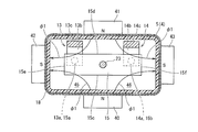
- the electromagnetic contactor 1 according to the first embodiment of the present invention shown in FIG. 1 includes a contact mechanism 2 and an electromagnet unit 20 that drives the contact mechanism 2.
- the contact mechanism 2 is housed in a contact housing case 4.
- the contact housing case 4 is made of a metal rectangular tube 5 and an insulating material such as ceramic or synthetic resin material that closes the upper end of the rectangular tube 5. And an insulating substrate 6 formed.
- the contact mechanism 2 includes a pair of fixed contacts 13 and 14 (hereinafter referred to as a first fixed contact 13 and a second fixed contact) fixed to the insulating substrate 6 via the conductor portions 11 and 12, and these The first and second fixed contacts 13a and 14a provided on the first and second fixed contacts 13 and 14 are provided with a movable contact 15 in which the first and second movable contacts 15a and 15b are opposed to each other.
- the first fixed contact 13 is equipped with a synthetic resin insulating cover 16 that restricts the occurrence of arc
- the second fixed contact 14 is also fitted with a synthetic resin insulating cover 17 that restricts the occurrence of arc.
- the movable contact 15 is supported by a connecting shaft 23 fixed to the movable plunger 22 of the electromagnet unit 20, and a through hole 24 through which the connecting shaft 23 is inserted is formed at the center of the movable contact 15.
- a flange portion 25 that protrudes outward is formed at the central portion of the connecting shaft 23 in the longitudinal direction.
- the contact spring 26 applies a predetermined urging force to the movable contact 15 by fixing the upper end of the contact spring 26 with a C ring 27 fixed to the upper end of the connecting shaft 23.
- an insulating cylinder portion 18 formed in a bottomed rectangular tube shape is disposed on the inner peripheral surface of the rectangular tube body 5 of the contact storage case 4.
- the insulating cylinder portion 18 is formed by molding an insulating synthetic resin, for example, and has an insulating function of blocking the influence of the arc on the metal square cylinder body 5.
- the electromagnet unit 20 has a U-shaped magnetic yoke 28 that is flat when viewed from the side.
- a fixed plunger 29 is disposed at the center of the bottom plate of the magnetic yoke 28, and a spool 30 is disposed outside the fixed plunger 29.
- the spool 30 includes a central cylindrical portion 31 through which the fixed plunger 29 is inserted, a lower flange portion 32 projecting radially outward from the lower end portion of the central cylindrical portion 31, and a slightly lower side than the upper end of the central cylindrical portion 31.
- the upper flange portion 33 projects outward in the radial direction.
- An exciting coil 34 is wound around a storage space formed by the central cylindrical portion 31, the lower flange portion 32, and the upper flange portion 33.
- the upper magnetic yoke 21 fixed to the upper end serving as the open end of the magnetic yoke 28 is formed with a through hole 21 a facing the central cylindrical portion 31 of the spool 30 in the central portion.
- An upper portion of the fixed plunger 29 inserted into the central cylindrical portion 31 of the spool 30 is covered with a cap 35 formed in a bottomed cylindrical shape, and is formed by extending radially outward at an open end of the cap 35.
- the flange portion 35 a is sealed and joined to the lower surface of the upper magnetic yoke 21. As a result, a sealed container is formed in which the cap 35 communicates with the upper magnetic yoke 21 through the through hole 21a.
- a movable plunger 22 having a return spring 36 disposed at the bottom is inserted into the cap 35 so as to be slidable up and down.
- the movable plunger 22 is formed with a peripheral flange portion 22 a that protrudes radially outward at an upper end portion that protrudes upward from the upper magnetic yoke 21.
- an annular driving permanent magnet 37 is fixed on the upper surface of the upper magnetic yoke 21 so as to surround the peripheral flange portion 22 a of the movable plunger 22.
- the driving permanent magnet 37 is magnetized in the vertical direction, that is, in the thickness direction so that, for example, the upper end side is an N pole and the lower end side is an S pole.
- An auxiliary yoke 39 having a through hole 38 having the same outer shape as the driving permanent magnet 37 and an inner diameter smaller than the outer diameter of the peripheral flange portion 22a of the movable plunger 22 is fixed to the upper end surface of the driving permanent magnet 37.
- the peripheral flange portion 22 a of the movable plunger 22 is in contact with the lower surface of the auxiliary yoke 39.
- a gas such as hydrogen gas, nitrogen gas, a mixed gas of hydrogen and nitrogen, air, or SF 6 is sealed in the sealed contact housing case 4.
- the movable contact 15 that constitutes the contact mechanism 2 is a conductive plate that is long in the left-right direction in FIG. 1 and made of copper, aluminum, or the like, and has a connecting shaft 23 connected to the center in the longitudinal direction.
- a first movable contact 15a and a second movable contact 15b are formed on the lower surfaces at both ends in the direction.
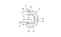
- the first fixed contact 13 and the second fixed contact 14 constituting the contact mechanism 2 are C-shaped conductive plates made of copper, aluminum, or the like, and are movable contacts.
- the elements 15 are spaced apart from each other in the longitudinal direction, and are fixed to the insulating substrate 6 via the conductor portions 11 and 12.
- the first fixed contact 13 is disposed on the first movable contact 15a side of the movable contact 15 in a direction orthogonal to the longitudinal direction, and faces the first movable contact 15a of the movable contact 15 from below.
- the first conductive plate portion 13b provided with the first fixed contact 13a on the upper surface, and the second conductive member bent from the end of the first conductive plate portion 13b away from the movable contact 15 and extending upward.
- a plate portion 13c and a third conductive plate portion 13d that is bent from the upper end of the second conductive plate portion 13c and extends above the movable contact 15 are provided.
- the second fixed contact 14 is disposed perpendicular to the longitudinal direction on the second movable contact 15 b side of the movable contact 15 and parallel to the first fixed contact 13. 2 is opposed to the movable contact 15b from the lower side and is bent from the end of the first conductive plate 14b provided with the second fixed contact 14a on the upper surface and the first conductive plate 14b away from the movable contact 15 And a third conductive plate portion 14d that is bent from the upper end of the second conductive plate portion 14c and extends above the movable contact 15. .
- the movable contact 15 is in a released state, and the movable contacts 15a, 15a located on both ends in the longitudinal direction and the fixed contacts 13a, 14a of the fixed contacts 13, 14 are spaced apart from each other with a predetermined interval. It becomes. Further, the movable contact 15 is set so that the movable contacts 15 a and 15 b are in contact with the fixed contacts 13 a and 14 a of the fixed contacts 13 and 14 with a predetermined contact pressure by the contact spring 26 at the closing position. .
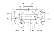
- first to fourth arc extinguishing permanent magnets 40 to 43 are arranged on the outer periphery of the rectangular tube 5.
- the first arc extinguishing permanent magnet 40 is fixed to the outer peripheral surface of the rectangular tube 5 facing the one side surface 15c in the width direction of the movable contact 15, and the second arc extinguishing permanent magnet 41 is
- the movable contact 15 is fixed to the outer peripheral surface of the rectangular tube 5 facing the other side surface 15d in the width direction.
- the first and second arc extinguishing side permanent magnets 41 and 42 are magnetized so that the magnetic pole surfaces in contact with the rectangular tube 5 in the thickness direction are N poles.
- the third arc extinguishing permanent magnet 42 is fixed to the outer peripheral surface of the rectangular tube 5 facing one side surface 15e in the longitudinal direction of the movable contact 15, and the fourth arc extinguishing permanent magnet 43. Is fixed to the outer peripheral surface of the rectangular tube 5 facing the other side surface 15f in the longitudinal direction of the movable contact 15.
- the third and fourth arc extinguishing side permanent magnets 42 and 43 are magnetized so that the magnetic pole surface in contact with the rectangular tube 5 in the thickness direction becomes the S pole.
- the first to fourth arc extinguishing permanent magnets 40 to 44 are fixed to the outer peripheral surface of the rectangular tube body 5 constituting the contact housing case 4.
- the magnetic flux ⁇ 1 flowing through the first fixed contact 13 passes through the vicinity of the opposed portion of the first fixed contact 13a of the first fixed contact 13 and the first movable contact 15a of the movable contact 15, and increases in magnetic flux density toward the left side in the left-right direction. Cross at.
- the magnetic flux ⁇ 1 flowing through the S pole of the fourth arc extinguishing permanent magnet 43 passes near a portion where the second fixed contact 14a of the second fixed contact 14 and the second movable contact 15b of the movable contact 15 are opposed to each other. Crossing with a large magnetic flux density toward the right side in the horizontal direction.
- the pair of fixed contacts 13, 14 arranged in the contact housing case 4 are arranged on both ends in the longitudinal direction of the movable contact 15 and on the other side surface 15 d side in the width direction.
- the arc extinguishing space 45 is disposed on one side 15c side in the width direction of the movable contact 15 opposite to the pair of fixed contacts 13 and 14, and extends in a direction orthogonal to the direction. 46 is formed.
- the insulating case of the present invention corresponds to the insulating covers 16 and 17 and the insulating cylindrical portion 18, and the fixed contact of the present invention corresponds to the first fixed contact 13a and the second fixed contact 14a, and the pair of movable members of the present invention.
- the contact corresponds to the first movable contact 15a and the second movable contact 15b
- the arc extinguishing permanent magnet of the present invention corresponds to the first to fourth arc extinguishing permanent magnets 40 to 43, and the movable iron core of the present invention.
- the electromagnet for operation of the present invention corresponds to the electromagnet unit 20.
- the attractive force generated by the magnetic force of the driving permanent magnet 37 acts on the auxiliary yoke 39, and the peripheral flange portion 22a of the movable plunger 22 is attracted. For this reason, the upper surface of the peripheral flange portion 22 a of the movable plunger 22 is in contact with the lower surface of the auxiliary yoke 39.
- the first movable contact 15 a and the second movable contact 15 b of the movable contact 15 of the contact mechanism 2 connected to the movable plunger 22 via the connecting shaft 23 are the first fixed contact of the first fixed contact 13. 13a is spaced apart from the second fixed contact 14a of the second fixed contact 14 upward by a predetermined distance. For this reason, the current path between the first fixed contact 13 and the second fixed contact 14 is in a cut-off state, and the contact mechanism 2 is in an open state.
- the exciting coil 34 of the electromagnet unit 20 is energized from this released state, an exciting force is generated in the electromagnet unit 20, and the movable plunger 22 is resisted against the urging force of the return spring 36 and the attracting force of the driving permanent magnet 37. Press down.
- the lowering of the movable plunger 22 stops when the lower surface of the peripheral flange portion 22 a hits the upper surface of the upper magnetic yoke 21.
- the movable contact 15 connected to the movable plunger 22 via the connecting shaft 23 is also lowered, and the first movable contact 15a of the movable contact 15 of the contact mechanism 2 is lowered.
- the second movable contact 15 b comes into contact with the first fixed contact 13 a of the first fixed contact 13 and the second fixed contact 14 a of the second fixed contact 14 with the contact pressure of the contact spring 26. For this reason, a large current from the power supply source is brought into a closed state in which it is supplied to the load device through the first fixed contact 13, the movable contact 15 and the second fixed contact 14.
- the first movable contact 15 a and the second movable contact 15 b of the movable contact 15 are connected to the first fixed contact 13 a and the second fixed contact 13 of the first fixed contact 13.
- the contact 14 is in contact with the second fixed contact 14a.
- a first arc 50 is generated between the first movable contact 15a of the movable contact 15 and the first fixed contact 13a of the first fixed contact 13 as shown in FIG.
- a second arc 51 is generated between the second movable contact 15 b of the movable contact 15 and the second fixed contact 14 a of the second fixed contact 14, and the current conduction state is continued by these arcs 50, 51.
- the current direction of the first arc 50 is a direction from the first fixed contact 13a to the first movable contact 15a
- the current direction of the second arc 51 is from the second movable contact 15b to the second fixed contact 14a. It is the direction to go.
- the magnetic flux ⁇ 1 flowing out from the N pole of the magnet 41 and flowing to the S pole of the third arc extinguishing permanent magnet 42 passes near the first arc 50 and is on one side surface 15e in the longitudinal direction of the movable contact 15. Occurs outward.
- a magnetic flux ⁇ 1 flowing through the S pole of the fourth arc extinguishing permanent magnet 43 is generated toward the outside of the other side surface 15f in the longitudinal direction of the movable contact 15 through the vicinity of the second arc 51.
- the first fixed contact 13 is arranged in the order of the conductor portion 11 to the third conductive plate portion 13 d, the second conductive plate portion 13 c, and the first conductive plate portion 13 b.
- Current flows, and a magnetic flux ⁇ 2 due to the current is generated around each third conductive plate portion 13d, second conductive plate portion 13c, and first conductive plate portion 13b.
- a current flows through the second fixed contact 14 in the order of the first conductive plate portion 14b, the second conductive plate portion 14c, and the third conductive plate portion 13d.
- Magnetic flux ⁇ 2 due to current is generated around the portion 14b, the second conductive plate portion 14c, and the third conductive plate portion 13d.
- the first fixed contact 13a of the first fixed contact 13 and the first movable contact 15a of the movable contact 15a of the movable contact 15 As shown in FIG. 7, the first fixed contact 13a side to the first movable contact 15a side One arc 50 flows, and a magnetic flux ⁇ 1 generated by the first arc extinguishing permanent magnet 40, the second arc extinguishing permanent magnet 41, and the third arc extinguishing permanent magnet 42 is one of the longitudinal directions of the movable contact 15.
- the magnetic flux ⁇ 2 is generated by the current that flows toward the outside of the side surface 15e and flows through the first fixed contact 13.
- the second arc 51 flows through the first arc extinguishing permanent magnet 40, the second arc extinguishing permanent magnet 41, and the fourth arc extinguishing permanent magnet 43 so that the magnetic flux ⁇ 1 is generated in the longitudinal direction of the movable contact 15. Is generated toward the outside of the other side surface 15f, and a magnetic flux ⁇ 2 is generated by the current flowing through the second fixed contact 14.
- the direction in which the current of the first arc 50 flows and the direction of the current flowing in the second conductive plate portion 13 c of the first fixed contact 13 are reversed. Due to this, the electromagnetic repulsive force works and the first arc 50 is stretched toward the arc extinguishing space 45. Furthermore, as shown in FIG. 8, the direction of the current flowing through the second arc 51 and the direction of the current flowing through the second conductive plate portion 14c of the second fixed contact 14 are reversed, and the currents in the opposite directions are reversed. Due to this, the electromagnetic repulsive force works, and the second arc 51 is stretched toward the arc extinguishing space 46.
- the first arc 50 can be reliably extinguished.
- a large current of several K amperes flows between the second fixed contact 14a and the second movable contact 15b, the first arc extinguishing permanent magnet 40, the second arc extinguishing permanent magnet 41, and the second The magnetic flux ⁇ 1 generated by the four-arc extinguishing permanent magnet 43, the magnetic flux ⁇ 2 generated by the current flowing through the second fixed contact 14, and the second generated between the second fixed contact 14a and the second movable contact 15b.
- the direction in which the current of the first arc 50 flows and the direction of the current flowing in the second conductive plate portion 13c of the first fixed contact 13 are reversed, and the action of the electromagnetic repulsive force due to the reverse direction of these currents. Since the first arc 50 is further extended toward the arc extinguishing space 45, the arc extinguishing of the first arc 50 can be promoted. Similarly, the direction in which the current of the second arc 51 flows and the direction of the current flowing in the second conductive plate portion 14c of the second stationary contact 14 are reversed, and the action of electromagnetic repulsive force due to the reverse direction of these currents. Since the second arc 51 is further stretched toward the arc extinguishing space 46, the arc extinguishing of the second arc 51 can be promoted.
- the first fixed contact 13 (and the second fixed contact 14) constituting the contact mechanism 2 is formed of a C-shaped conductive plate in a side view.
- the first movable contact 15a (and the second movable contact 15b side) of the movable contact 15 and the first movable contact 15a (and the second movable contact 15b) from the lower side are not limited thereto.
- the first conductive plate portion provided with the first fixed contact (and the second fixed contact) on the upper surface and the first conductive plate portion remote from the movable contact 15 are bent and extended upward. It may be a conductive plate having an L shape in a side view and formed of a second conductive plate portion.
- the first to fourth arc extinguishing permanent magnets 40 to 43 are fixed to the outer peripheral surface of the rectangular cylinder 5 constituting the contact housing case 4, but the present invention is not limited to this. Instead, it forms a magnetic flux that passes near the opposed portion of the first fixed contact 13a of the first fixed contact 13 and the first movable contact 15a of the movable contact 15 toward the left in the left-right direction, and the second Any other shape can be used as long as it forms a magnetic flux that passes near the opposing portion of the second fixed contact 14a of the fixed contact 14 and the second movable contact 15b of the movable contact 15 and moves to the right in the left-right direction.
- the permanent magnet may be arranged.
- the contact mechanism according to the present invention and the electromagnetic contactor using the contact mechanism generate a force that sufficiently stretches the arc even when a large current of several kiloamperes is interrupted, and have the arc extinguishing performance. Useful to improve.
- Electromagnetic contactor 2 ... Contact mechanism, 4 ... Contact storage case, 5 ... Square cylinder body, 6 ... Insulating substrate, 7 ... Flange part, 9,10 ... Through-hole, 11, 12 ... Conductor part, 13th 1 fixed contact, 13a ... 1st fixed contact, 13b ... 1st conductive plate part, 13c ... 2nd conductive plate part, 13d ... 3rd conductive plate part, 14 ... 2nd fixed contact, 14a ... 2nd fixed contact , 14b ... 1st conductive plate part, 14c ... 2nd conductive plate part, 14d ... 3rd conductive plate part, 15 ... movable contact, 15a ...
Abstract
The contact point mechanism comprises: a pair of fixed contact-makers (13, 14), each having a fixed contact point (13a, 14a); a mobile contact-maker (15) provided with a pair of mobile contact points (15a, 15b) at two end sides in the length direction thereof, said pair of mobile contact points being capable of establishing contact with and separating from the fixed contact points (13a, 14a) of the pair of fixed contact-makers; a case (16, 17, 18) formed from an insulating material and housing the pair of fixed contact-makers and the mobile contact-maker; and arc-extinguishing permanent magnets (40 to 43) fixed to the case (16, 17, 18). The currents from the arcs (50, 51) generated between the fixed contact points and the mobile contact points and the magnetic flux from the arc-extinguishing permanent magnets (40 to 43) cause Lorentz forces (F1, F2) to be generated by the arcs (50, 51), while the pair of fixed contact-makers (13, 14) are such that the magnetic fluxes generated by the current flowing therein match the magnetic fluxes of the arc-extinguishing permanent magnets (40 to 43).
Description
本発明は、電流路の開閉を行う接点機構及びこれを使用した電磁接触器に関する。
The present invention relates to a contact mechanism for opening and closing a current path and an electromagnetic contactor using the contact mechanism.
電流遮断時にアークが発生する電磁接触器などに適用する接点機構として、例えば特許文献1に記載されているものが知られている。この特許文献1の接点機構は、所定間隔を設けて配置されている一対の固定接触子と、これら一対の固定接触子に対して接離自在に配置されている可動接触子と、これら一対の固定接触子及び可動接触子を収納している絶縁材で形成した接点収納ケースと、を備えている。そして、接点収納ケース内の可動接触子に沿う対向内周面に、それぞれ互いの対向磁極面を同一極性に着磁した一対のアーク消弧用内側永久磁石を可動接触子に近接させて配置し、接点収納ケースの一対のアーク消弧用内側永久磁石のそれぞれに対向する外周面の位置に、アーク消弧用内側永久磁石と同極性で且つ当該アーク消弧用内側永久磁石より保磁力が大きい一対のアーク消弧用外側永久磁石を配置している。
As a contact mechanism applied to an electromagnetic contactor that generates an arc when a current is interrupted, for example, a contact mechanism described in Patent Document 1 is known. The contact mechanism of Patent Document 1 includes a pair of fixed contacts arranged at a predetermined interval, a movable contact arranged so as to be able to contact with and separate from the pair of fixed contacts, and the pair of contacts. And a contact storage case formed of an insulating material that stores the stationary contact and the movable contact. Then, a pair of arc-extinguishing inner permanent magnets, which are magnetized with the same polarity on the opposing magnetic pole surfaces, are arranged close to the movable contact on the opposed inner peripheral surface along the movable contact in the contact housing case. In the contact housing case, at the position of the outer peripheral surface facing each of the pair of arc extinguishing inner permanent magnets, the polarity is the same as that of the arc extinguishing inner permanent magnet and the coercive force is larger than that of the arc extinguishing inner permanent magnet. A pair of arc extinguishing outer permanent magnets are arranged.
この接点機構によると、一対の固定接触子間に可動接触子が接触している投入状態から釈放状態とする際に、一対の固定接触子と可動接触子との間にアークが発生すると、互いに対向配置されている各対のアーク消弧用内側永久磁石及びアーク消弧用外側永久磁石のN極からS極に向かう磁束が共に一対の固定接触子と可動接触子との間のアークが発生した位置に対して可動接触子の長手方向に横切ることになり、アークに対してローレンツ力を作用し、可動接触子の長手方向と直交する方向にアークを引き伸ばして消弧するようにしている。
According to this contact mechanism, when an arc is generated between the pair of fixed contacts and the movable contact when the movable contact is in contact with the pair of fixed contacts, the arc is generated between the pair of fixed contacts and the movable contact. The magnetic fluxes from the north pole to the south pole of each pair of the arc extinguishing inner permanent magnet and the arc extinguishing outer permanent magnet that are opposed to each other generate an arc between the pair of fixed and movable contacts. The position is traversed in the longitudinal direction of the movable contact, a Lorentz force is applied to the arc, and the arc is stretched in a direction perpendicular to the longitudinal direction of the movable contact to extinguish the arc.
ところで、特許文献1の装置は、永久磁石(アーク消弧用内側永久磁石及びアーク消弧用外側永久磁石の間)で発生する磁束のみでアークを引き伸ばしている。そのため、数Kアンペアの大電流を遮断する場合、発生したアークを引き伸ばす力が不足し、アークの伸長方向が変化して消弧性能が低下するおそれがある。
そこで、本発明は、数Kアンペアの大電流を遮断する場合であっても、十分にアークを引き伸ばす力を発生して消弧性能を向上させることができる接点機構及びこれを使用した電磁接触器を提供することを目的としている。 By the way, the apparatus ofpatent document 1 is extending the arc only with the magnetic flux generated by a permanent magnet (between the arc extinguishing inner permanent magnet and the arc extinguishing outer permanent magnet). Therefore, when interrupting a large current of several K amperes, the force for stretching the generated arc is insufficient, and the arc extinguishing direction may change to reduce the arc extinguishing performance.
Accordingly, the present invention provides a contact mechanism that can generate a force that sufficiently stretches an arc to improve arc extinguishing performance even when a large current of several kiloamperes is interrupted, and an electromagnetic contactor using the contact mechanism The purpose is to provide.
そこで、本発明は、数Kアンペアの大電流を遮断する場合であっても、十分にアークを引き伸ばす力を発生して消弧性能を向上させることができる接点機構及びこれを使用した電磁接触器を提供することを目的としている。 By the way, the apparatus of
Accordingly, the present invention provides a contact mechanism that can generate a force that sufficiently stretches an arc to improve arc extinguishing performance even when a large current of several kiloamperes is interrupted, and an electromagnetic contactor using the contact mechanism The purpose is to provide.
上記目的を達成するために、本発明の一態様に係る接点機構は、固定接点を有する一対の固定接触子と、これら一対の固定接触子の上記固定接点に接離可能な一対の可動接点を長手方向の両端側に設けた可動接触子と、上記一対の固定接触子及び上記可動接触子を収納している絶縁材で形成した接点収納ケースと、この接点収納ケースに固定したアーク消弧用永久磁石と、を備えている。そして、上記固定接点及び上記可動接点の間に発生するアークの電流と、上記アーク消弧用永久磁石の磁束とによって、上記アークにローレンツ力を発生させるとともに、上記一対の固定接触子は、自身を流れる電流によって発生する磁束が上記アーク消弧用永久磁石の磁束に一致するように構成している。
また、本発明の一態様に係る電磁接触器は、上記可動接触子が操作用電磁石の可動鉄心に連結され、上記固定接触子が外部接続端子に接続されている。 In order to achieve the above object, a contact mechanism according to an aspect of the present invention includes a pair of fixed contacts having fixed contacts and a pair of movable contacts that can contact and separate from the fixed contacts of the pair of fixed contacts. A movable contact provided on both ends in the longitudinal direction, a contact storage case formed of an insulating material storing the pair of fixed contacts and the movable contact, and arc extinguishing fixed to the contact storage case And a permanent magnet. The arc current generated between the fixed contact and the movable contact and the magnetic flux of the arc extinguishing permanent magnet generate a Lorentz force in the arc, and the pair of fixed contacts The magnetic flux generated by the current flowing through the arc extinguishing permanent magnet matches the magnetic flux of the arc extinguishing permanent magnet.
Moreover, the electromagnetic contactor which concerns on 1 aspect of this invention WHEREIN: The said movable contact is connected with the movable iron core of the electromagnet for operation, and the said stationary contact is connected to the external connection terminal.
本発明に係る接点機構及びこれを使用した電磁接触器によれば、固定接点及び可動接点の間に発生するアークの電流と、アーク消弧用永久磁石の磁束とによって、アークにローレンツ力を発生させるとともに、一対の固定接触子は、自身を流れる電流によって発生する磁束がアーク消弧用永久磁石の磁束に一致するように構成していることから、固定接点と可動接点との間に大電流が流れても、アーク消弧用永久磁石で発生する磁束と、固定接触子を流れる電流により発生する磁束と、固定接点と可動接点との間に発生したアークの電流の流れとの関係から、アークを引き伸ばす大きなローレンツ力が作用するので、アークの伸長方向を変化させずに消弧を確実に行うことができる。
According to the contact mechanism and the magnetic contactor using the same according to the present invention, the Lorentz force is generated in the arc by the arc current generated between the fixed contact and the movable contact and the magnetic flux of the arc extinguishing permanent magnet. In addition, since the pair of fixed contacts are configured such that the magnetic flux generated by the current flowing through them matches the magnetic flux of the arc extinguishing permanent magnet, a large current is generated between the fixed contact and the movable contact. From the relationship between the magnetic flux generated by the arc extinguishing permanent magnet, the magnetic flux generated by the current flowing through the fixed contact, and the current flow of the arc generated between the fixed contact and the movable contact, Since a large Lorentz force that stretches the arc acts, arc extinction can be reliably performed without changing the arc extension direction.
以下、本発明を実施するための形態(以下、実施形態という。)を、図面を参照しながら詳細に説明する。
図1に示す本発明に係る第1実施形態の電磁接触器1は、接点機構2と、この接点機構2を駆動する電磁石ユニット20とを備えている。
接点機構2は接点収納ケース4に収納されており、接点収納ケース4は、金属製の角筒体5と、この角筒体5の上端を閉塞する例えばセラミックや合成樹脂材などの絶縁材料により形成した絶縁基板6とを備えている。 DESCRIPTION OF EMBODIMENTS Hereinafter, modes for carrying out the present invention (hereinafter referred to as embodiments) will be described in detail with reference to the drawings.
Theelectromagnetic contactor 1 according to the first embodiment of the present invention shown in FIG. 1 includes a contact mechanism 2 and an electromagnet unit 20 that drives the contact mechanism 2.
The contact mechanism 2 is housed in acontact housing case 4. The contact housing case 4 is made of a metal rectangular tube 5 and an insulating material such as ceramic or synthetic resin material that closes the upper end of the rectangular tube 5. And an insulating substrate 6 formed.
図1に示す本発明に係る第1実施形態の電磁接触器1は、接点機構2と、この接点機構2を駆動する電磁石ユニット20とを備えている。
接点機構2は接点収納ケース4に収納されており、接点収納ケース4は、金属製の角筒体5と、この角筒体5の上端を閉塞する例えばセラミックや合成樹脂材などの絶縁材料により形成した絶縁基板6とを備えている。 DESCRIPTION OF EMBODIMENTS Hereinafter, modes for carrying out the present invention (hereinafter referred to as embodiments) will be described in detail with reference to the drawings.
The
The contact mechanism 2 is housed in a
角筒体5は、下部に形成したフランジ部7が電磁石ユニット20の上部磁気ヨーク21にシール接合されて固定されている。絶縁基板6には、貫通孔9,10が所定間隔をあけて形成されている。
接点機構2は、絶縁基板6に導体部11,12を介して固定されている一対の固定接触子13,14(以下、第1固定接触子13、第2固定接触子と称する)と、これら第1及び第2固定接触子13,14に設けた第1及び第2固定接点13a,14aに第1及び第2可動接点15a,15bが対向している可動接触子15とを備えている。 In therectangular tube 5, the flange portion 7 formed in the lower portion is fixed to the upper magnetic yoke 21 of the electromagnet unit 20 by sealing. Through holes 9 and 10 are formed in the insulating substrate 6 at a predetermined interval.
The contact mechanism 2 includes a pair offixed contacts 13 and 14 (hereinafter referred to as a first fixed contact 13 and a second fixed contact) fixed to the insulating substrate 6 via the conductor portions 11 and 12, and these The first and second fixed contacts 13a and 14a provided on the first and second fixed contacts 13 and 14 are provided with a movable contact 15 in which the first and second movable contacts 15a and 15b are opposed to each other.
接点機構2は、絶縁基板6に導体部11,12を介して固定されている一対の固定接触子13,14(以下、第1固定接触子13、第2固定接触子と称する)と、これら第1及び第2固定接触子13,14に設けた第1及び第2固定接点13a,14aに第1及び第2可動接点15a,15bが対向している可動接触子15とを備えている。 In the
The contact mechanism 2 includes a pair of
第1固定接触子13には、アークの発生を規制する合成樹脂性の絶縁カバー16が装着され、第2固定接触子14にも、アークの発生を規制する合成樹脂性の絶縁カバー17が装着されている。これにより、第1固定接触子13の内周面では、第1固定接点13aのみが露出し、第2固定接触子14の内周面では、第2固定接点14aのみが露出している。
可動接触子15は、電磁石ユニット20の可動プランジャ22に固定された連結軸23に支持されており、可動接触子15の中央部に連結軸23を挿通する貫通孔24が形成されている。 The first fixedcontact 13 is equipped with a synthetic resin insulating cover 16 that restricts the occurrence of arc, and the second fixed contact 14 is also fitted with a synthetic resin insulating cover 17 that restricts the occurrence of arc. Has been. Accordingly, only the first fixed contact 13 a is exposed on the inner peripheral surface of the first fixed contact 13, and only the second fixed contact 14 a is exposed on the inner peripheral surface of the second fixed contact 14.
Themovable contact 15 is supported by a connecting shaft 23 fixed to the movable plunger 22 of the electromagnet unit 20, and a through hole 24 through which the connecting shaft 23 is inserted is formed at the center of the movable contact 15.
可動接触子15は、電磁石ユニット20の可動プランジャ22に固定された連結軸23に支持されており、可動接触子15の中央部に連結軸23を挿通する貫通孔24が形成されている。 The first fixed
The
連結軸23の長手方向の中央部には外方に突出するフランジ部25が形成されており、可動接触子15の貫通孔24に連結軸23を上端から挿入することで、可動接触子15の中央下部をフランジ部25に当接し、連結軸23の上部から接触スプリング26を挿入する。そして、連結軸23の上端に固定したCリング27で接触スプリング26の上端を固定することで、接触スプリング26が可動接触子15に対して所定の付勢力を付与している。
また、接点収納ケース4の角筒体5の内周面には、有底角筒状に形成された絶縁筒部18が配設されている。この絶縁筒部18は、絶縁性の例えば合成樹脂を成形することによって形成され、金属製の角筒体5に対するアークの影響を遮断する絶縁機能を有する。 Aflange portion 25 that protrudes outward is formed at the central portion of the connecting shaft 23 in the longitudinal direction. By inserting the connecting shaft 23 into the through hole 24 of the movable contact 15 from the upper end, the movable contact 15 The lower center portion is brought into contact with the flange portion 25 and the contact spring 26 is inserted from the upper portion of the connecting shaft 23. The contact spring 26 applies a predetermined urging force to the movable contact 15 by fixing the upper end of the contact spring 26 with a C ring 27 fixed to the upper end of the connecting shaft 23.
Further, aninsulating cylinder portion 18 formed in a bottomed rectangular tube shape is disposed on the inner peripheral surface of the rectangular tube body 5 of the contact storage case 4. The insulating cylinder portion 18 is formed by molding an insulating synthetic resin, for example, and has an insulating function of blocking the influence of the arc on the metal square cylinder body 5.
また、接点収納ケース4の角筒体5の内周面には、有底角筒状に形成された絶縁筒部18が配設されている。この絶縁筒部18は、絶縁性の例えば合成樹脂を成形することによって形成され、金属製の角筒体5に対するアークの影響を遮断する絶縁機能を有する。 A
Further, an
電磁石ユニット20は、側面から見て扁平なU字形状の磁気ヨーク28を有し、この磁気ヨーク28の底板部の中央部に固定プランジャ29が配置され、この固定プランジャ29の外側にスプール30が配置されている。
スプール30は、固定プランジャ29を挿通する中央円筒部31と、この中央円筒部31の下端部から半径方向外方に突出する下フランジ部32と、中央円筒部31の上端より僅かに下側から半径方向外方に突出する上フランジ部33とで構成されている。そして、中央円筒部31、下フランジ部32及び上フランジ部33で構成される収納空間に励磁コイル34が巻装されている。 Theelectromagnet unit 20 has a U-shaped magnetic yoke 28 that is flat when viewed from the side. A fixed plunger 29 is disposed at the center of the bottom plate of the magnetic yoke 28, and a spool 30 is disposed outside the fixed plunger 29. Has been placed.
Thespool 30 includes a central cylindrical portion 31 through which the fixed plunger 29 is inserted, a lower flange portion 32 projecting radially outward from the lower end portion of the central cylindrical portion 31, and a slightly lower side than the upper end of the central cylindrical portion 31. The upper flange portion 33 projects outward in the radial direction. An exciting coil 34 is wound around a storage space formed by the central cylindrical portion 31, the lower flange portion 32, and the upper flange portion 33.
スプール30は、固定プランジャ29を挿通する中央円筒部31と、この中央円筒部31の下端部から半径方向外方に突出する下フランジ部32と、中央円筒部31の上端より僅かに下側から半径方向外方に突出する上フランジ部33とで構成されている。そして、中央円筒部31、下フランジ部32及び上フランジ部33で構成される収納空間に励磁コイル34が巻装されている。 The
The
磁気ヨーク28の開放端となる上端に固定した上部磁気ヨーク21には、中央部にスプール30の中央円筒部31に対向する貫通孔21aが形成されている。
スプール30の中央円筒部31内に挿入された固定プランジャ29の上部には、有底筒状に形成されたキャップ35で覆われ、このキャップ35の開放端に半径方向外方に延長して形成されたフランジ部35aが上部磁気ヨーク21の下面にシール接合されている。これによって、キャップ35が上部磁気ヨーク21の貫通孔21aを介して連通される密封容器が形成される。 The uppermagnetic yoke 21 fixed to the upper end serving as the open end of the magnetic yoke 28 is formed with a through hole 21 a facing the central cylindrical portion 31 of the spool 30 in the central portion.
An upper portion of thefixed plunger 29 inserted into the central cylindrical portion 31 of the spool 30 is covered with a cap 35 formed in a bottomed cylindrical shape, and is formed by extending radially outward at an open end of the cap 35. The flange portion 35 a is sealed and joined to the lower surface of the upper magnetic yoke 21. As a result, a sealed container is formed in which the cap 35 communicates with the upper magnetic yoke 21 through the through hole 21a.
スプール30の中央円筒部31内に挿入された固定プランジャ29の上部には、有底筒状に形成されたキャップ35で覆われ、このキャップ35の開放端に半径方向外方に延長して形成されたフランジ部35aが上部磁気ヨーク21の下面にシール接合されている。これによって、キャップ35が上部磁気ヨーク21の貫通孔21aを介して連通される密封容器が形成される。 The upper
An upper portion of the
キャップ35の内部に、最下部に復帰スプリング36を配置した可動プランジャ22が上下に摺動可能に挿入される。この可動プランジャ22には、上部磁気ヨーク21から上方に突出する上端部に半径方向外方に突出する周鍔部22aが形成されている。
また、上部磁気ヨーク21の上面に、環状に形成された駆動用永久磁石37が可動プランジャ22の周鍔部22aを囲むように固定されている。この駆動用永久磁石37は上下方向すなわち厚み方向に例えば上端側をN極とし、下端側をS極とするように着磁されている。 Amovable plunger 22 having a return spring 36 disposed at the bottom is inserted into the cap 35 so as to be slidable up and down. The movable plunger 22 is formed with a peripheral flange portion 22 a that protrudes radially outward at an upper end portion that protrudes upward from the upper magnetic yoke 21.
Further, an annular drivingpermanent magnet 37 is fixed on the upper surface of the upper magnetic yoke 21 so as to surround the peripheral flange portion 22 a of the movable plunger 22. The driving permanent magnet 37 is magnetized in the vertical direction, that is, in the thickness direction so that, for example, the upper end side is an N pole and the lower end side is an S pole.
また、上部磁気ヨーク21の上面に、環状に形成された駆動用永久磁石37が可動プランジャ22の周鍔部22aを囲むように固定されている。この駆動用永久磁石37は上下方向すなわち厚み方向に例えば上端側をN極とし、下端側をS極とするように着磁されている。 A
Further, an annular driving
そして、駆動用永久磁石37の上端面に、駆動用永久磁石37と同一外形で可動プランジャ22の周鍔部22aの外径より小さい内径の貫通孔38を有する補助ヨーク39が固定されており、この補助ヨーク39の下面に、可動プランジャ22の周鍔部22aが接触している。
そして、密閉された接点収納ケース4に水素ガス、窒素ガス、水素及び窒素の混合ガス、空気、SF6等のガスが封入されている。
接点機構2を構成する可動接触子15は、銅、アルミニウムなどを材料とした図1の左右方向に長尺な導電板であり、長手方向の中央部に連結軸23が連結されており、長手方向の両端側の下面に、第1可動接点15a及び第2可動接点15bが形成されている。 Anauxiliary yoke 39 having a through hole 38 having the same outer shape as the driving permanent magnet 37 and an inner diameter smaller than the outer diameter of the peripheral flange portion 22a of the movable plunger 22 is fixed to the upper end surface of the driving permanent magnet 37. The peripheral flange portion 22 a of the movable plunger 22 is in contact with the lower surface of the auxiliary yoke 39.
A gas such as hydrogen gas, nitrogen gas, a mixed gas of hydrogen and nitrogen, air, or SF 6 is sealed in the sealedcontact housing case 4.
Themovable contact 15 that constitutes the contact mechanism 2 is a conductive plate that is long in the left-right direction in FIG. 1 and made of copper, aluminum, or the like, and has a connecting shaft 23 connected to the center in the longitudinal direction. A first movable contact 15a and a second movable contact 15b are formed on the lower surfaces at both ends in the direction.
そして、密閉された接点収納ケース4に水素ガス、窒素ガス、水素及び窒素の混合ガス、空気、SF6等のガスが封入されている。
接点機構2を構成する可動接触子15は、銅、アルミニウムなどを材料とした図1の左右方向に長尺な導電板であり、長手方向の中央部に連結軸23が連結されており、長手方向の両端側の下面に、第1可動接点15a及び第2可動接点15bが形成されている。 An
A gas such as hydrogen gas, nitrogen gas, a mixed gas of hydrogen and nitrogen, air, or SF 6 is sealed in the sealed
The
接点機構2を構成する第1固定接触子13及び第2固定接触子14は、図1から図3に示すように、銅、アルミニウムなどからなる側面視C字形状の導電板であり、可動接触子15の長手方向の両端側に離間し、前述した絶縁基板6に導体部11,12を介して固定されている。
第1固定接触子13は、可動接触子15の第1可動接点15a側に、長手方向に対して直交する方向に配置されており、可動接触子15の第1可動接点15aに下側から対向し、第1固定接点13aを上面に設けた第1導電板部13bと、可動接触子15から離れた第1導電板部13bの端部から折り曲げられて上方に延在している第2導電板部13cと、第2導電板部13cの上端から折り曲げられて可動接触子15の上方に延在している第3導電板部13dと、を備えている。 As shown in FIGS. 1 to 3, the first fixedcontact 13 and the second fixed contact 14 constituting the contact mechanism 2 are C-shaped conductive plates made of copper, aluminum, or the like, and are movable contacts. The elements 15 are spaced apart from each other in the longitudinal direction, and are fixed to the insulating substrate 6 via the conductor portions 11 and 12.
The first fixedcontact 13 is disposed on the first movable contact 15a side of the movable contact 15 in a direction orthogonal to the longitudinal direction, and faces the first movable contact 15a of the movable contact 15 from below. The first conductive plate portion 13b provided with the first fixed contact 13a on the upper surface, and the second conductive member bent from the end of the first conductive plate portion 13b away from the movable contact 15 and extending upward. A plate portion 13c and a third conductive plate portion 13d that is bent from the upper end of the second conductive plate portion 13c and extends above the movable contact 15 are provided.
第1固定接触子13は、可動接触子15の第1可動接点15a側に、長手方向に対して直交する方向に配置されており、可動接触子15の第1可動接点15aに下側から対向し、第1固定接点13aを上面に設けた第1導電板部13bと、可動接触子15から離れた第1導電板部13bの端部から折り曲げられて上方に延在している第2導電板部13cと、第2導電板部13cの上端から折り曲げられて可動接触子15の上方に延在している第3導電板部13dと、を備えている。 As shown in FIGS. 1 to 3, the first fixed
The first fixed
また、第2固定接触子14は、可動接触子15の第2可動接点15b側に長手方向に対して直交し、第1固定接触子13に平行に配置されており、可動接触子15の第2可動接点15bに下側から対向し、第2固定接点14aを上面に設けた第1導電板部14bと、可動接触子15から離れた第1導電板部14bの端部から折り曲げられて上方に延在している第2導電板部14cと、第2導電板部14cの上端から折り曲げられて可動接触子15の上方に延在している第3導電板部14dと、を備えている。
そして、可動接触子15は、釈放状態で、長手方向の両端側に位置する可動接点15a,15aと、固定接触子13,14の固定接点13a,14aとが、所定間隔を保って離間した状態となる。
また、可動接触子15は、投入位置で、可動接点15a,15bが、固定接触子13,14の固定接点13a,14aに、接触スプリング26による所定の接触圧で接触するように設定されている。 The second fixedcontact 14 is disposed perpendicular to the longitudinal direction on the second movable contact 15 b side of the movable contact 15 and parallel to the first fixed contact 13. 2 is opposed to the movable contact 15b from the lower side and is bent from the end of the first conductive plate 14b provided with the second fixed contact 14a on the upper surface and the first conductive plate 14b away from the movable contact 15 And a third conductive plate portion 14d that is bent from the upper end of the second conductive plate portion 14c and extends above the movable contact 15. .
Themovable contact 15 is in a released state, and the movable contacts 15a, 15a located on both ends in the longitudinal direction and the fixed contacts 13a, 14a of the fixed contacts 13, 14 are spaced apart from each other with a predetermined interval. It becomes.
Further, themovable contact 15 is set so that the movable contacts 15 a and 15 b are in contact with the fixed contacts 13 a and 14 a of the fixed contacts 13 and 14 with a predetermined contact pressure by the contact spring 26 at the closing position. .
そして、可動接触子15は、釈放状態で、長手方向の両端側に位置する可動接点15a,15aと、固定接触子13,14の固定接点13a,14aとが、所定間隔を保って離間した状態となる。
また、可動接触子15は、投入位置で、可動接点15a,15bが、固定接触子13,14の固定接点13a,14aに、接触スプリング26による所定の接触圧で接触するように設定されている。 The second fixed
The
Further, the
一方、図4に示すように、角筒体5の外周には、第1~第4アーク消弧用永久磁石40~43が配置されている。
第1アーク消弧用永久磁石40は、可動接触子15の幅方向の一方の側面15cに対向している角筒体5の外周面に固定され、第2アーク消弧用永久磁石41は、可動接触子15の幅方向の他方の側面15dに対向している角筒体5の外周面に固定されている。
これら第1及び第2アーク消弧用側永久磁石41,42は、厚み方向の角筒体5に接する磁極面がN極となるように着磁されている。
また、第3アーク消弧用永久磁石42は、可動接触子15の長手方向の一方の側面15eに対向している角筒体5の外周面に固定され、第4アーク消弧用永久磁石43は、可動接触子15の長手方向の他方の側面15fに対向している角筒体5の外周面に固定されている。
これら第3及び第4アーク消弧用側永久磁石42,43は、厚み方向の角筒体5に接する磁極面がS極となるように着磁されている。 On the other hand, as shown in FIG. 4, first to fourth arc extinguishingpermanent magnets 40 to 43 are arranged on the outer periphery of the rectangular tube 5.
The first arc extinguishingpermanent magnet 40 is fixed to the outer peripheral surface of the rectangular tube 5 facing the one side surface 15c in the width direction of the movable contact 15, and the second arc extinguishing permanent magnet 41 is The movable contact 15 is fixed to the outer peripheral surface of the rectangular tube 5 facing the other side surface 15d in the width direction.
The first and second arc extinguishing side permanent magnets 41 and 42 are magnetized so that the magnetic pole surfaces in contact with the rectangular tube 5 in the thickness direction are N poles.
The third arc extinguishingpermanent magnet 42 is fixed to the outer peripheral surface of the rectangular tube 5 facing one side surface 15e in the longitudinal direction of the movable contact 15, and the fourth arc extinguishing permanent magnet 43. Is fixed to the outer peripheral surface of the rectangular tube 5 facing the other side surface 15f in the longitudinal direction of the movable contact 15.
The third and fourth arc extinguishing side permanent magnets 42 and 43 are magnetized so that the magnetic pole surface in contact with the rectangular tube 5 in the thickness direction becomes the S pole.
第1アーク消弧用永久磁石40は、可動接触子15の幅方向の一方の側面15cに対向している角筒体5の外周面に固定され、第2アーク消弧用永久磁石41は、可動接触子15の幅方向の他方の側面15dに対向している角筒体5の外周面に固定されている。
これら第1及び第2アーク消弧用側永久磁石41,42は、厚み方向の角筒体5に接する磁極面がN極となるように着磁されている。
また、第3アーク消弧用永久磁石42は、可動接触子15の長手方向の一方の側面15eに対向している角筒体5の外周面に固定され、第4アーク消弧用永久磁石43は、可動接触子15の長手方向の他方の側面15fに対向している角筒体5の外周面に固定されている。
これら第3及び第4アーク消弧用側永久磁石42,43は、厚み方向の角筒体5に接する磁極面がS極となるように着磁されている。 On the other hand, as shown in FIG. 4, first to fourth arc extinguishing
The first arc extinguishing
The first and second arc extinguishing side
The third arc extinguishing
The third and fourth arc extinguishing side
これにより、接点収納ケース4を構成する角筒体5の外周面に第1~第4アーク消弧用永久磁石40~44が固定されていることから、第1アーク消弧用永久磁石40のN極から出て第3アーク消弧用永久磁石42のS極に流れる磁束φ1と、第2アーク消弧用永久磁石41のN極から出て第3アーク消弧用永久磁石42のS極に流れる磁束φ1とが、第1固定接触子13の第1固定接点13aと可動接触子15の第1可動接点15aとの対向部の近くを通過して左右方向の左側に向って大きな磁束密度で横切る。
また、第1アーク消弧用永久磁石40のN極から出て第4アーク消弧用永久磁石43のS極に流れる磁束φ1と、第2アーク消弧用永久磁石41のN極から出て第4アーク消弧用永久磁石43のS極に流れる磁束φ1が、第2固定接触子14の第2固定接点14aと可動接触子15の第2可動接点15bとの対向部の近くを通過して左右方向の右側に向って大きな磁束密度で横切る。 As a result, the first to fourth arc extinguishingpermanent magnets 40 to 44 are fixed to the outer peripheral surface of the rectangular tube body 5 constituting the contact housing case 4. The magnetic flux φ1 flowing out from the N pole and flowing into the S pole of the third arc extinguishing permanent magnet 42 and the S pole of the third arc extinguishing permanent magnet 42 coming out of the N pole of the second arc extinguishing permanent magnet 41 The magnetic flux φ1 flowing through the first fixed contact 13 passes through the vicinity of the opposed portion of the first fixed contact 13a of the first fixed contact 13 and the first movable contact 15a of the movable contact 15, and increases in magnetic flux density toward the left side in the left-right direction. Cross at.
Further, the magnetic flux φ1 that flows out from the N pole of the first arc extinguishingpermanent magnet 40 and flows into the S pole of the fourth arc extinguishing permanent magnet 43 and the N pole of the second arc extinguishing permanent magnet 41. The magnetic flux φ1 flowing through the S pole of the fourth arc extinguishing permanent magnet 43 passes near a portion where the second fixed contact 14a of the second fixed contact 14 and the second movable contact 15b of the movable contact 15 are opposed to each other. Crossing with a large magnetic flux density toward the right side in the horizontal direction.
また、第1アーク消弧用永久磁石40のN極から出て第4アーク消弧用永久磁石43のS極に流れる磁束φ1と、第2アーク消弧用永久磁石41のN極から出て第4アーク消弧用永久磁石43のS極に流れる磁束φ1が、第2固定接触子14の第2固定接点14aと可動接触子15の第2可動接点15bとの対向部の近くを通過して左右方向の右側に向って大きな磁束密度で横切る。 As a result, the first to fourth arc extinguishing
Further, the magnetic flux φ1 that flows out from the N pole of the first arc extinguishing
また、図4に示すように、接点収納ケース4内に配置された一対の固定接触子13,14は、可動接触子15の長手方向の両端側に、幅方向の他方の側面15d側の長手方向に直交する方向に延在して配置されており、一対の固定接触子13,14に対して逆側の可動接触子15の幅方向の一方の側面15c側に、アーク消弧空間45、46が形成されている。
ここで、本発明の絶縁ケースが絶縁カバー16,17及び絶縁筒部18に対応し、本発明の固定接点が第1固定接点13aと第2固定接点14aに対応し、本発明の一対の可動接点が第1可動接点15a,第2可動接点15bに対応し、本発明のアーク消弧用永久磁石が第1~第4アーク消弧用永久磁石40~43に対応し、本発明の可動鉄心が可動プランジャ22に対応し、本発明の操作用電磁石が電磁石ユニット20に対応している。 Further, as shown in FIG. 4, the pair of fixed contacts 13, 14 arranged in the contact housing case 4 are arranged on both ends in the longitudinal direction of the movable contact 15 and on the other side surface 15 d side in the width direction. The arc extinguishing space 45 is disposed on one side 15c side in the width direction of the movable contact 15 opposite to the pair of fixed contacts 13 and 14, and extends in a direction orthogonal to the direction. 46 is formed.
Here, the insulating case of the present invention corresponds to the insulating covers 16 and 17 and the insulatingcylindrical portion 18, and the fixed contact of the present invention corresponds to the first fixed contact 13a and the second fixed contact 14a, and the pair of movable members of the present invention. The contact corresponds to the first movable contact 15a and the second movable contact 15b, and the arc extinguishing permanent magnet of the present invention corresponds to the first to fourth arc extinguishing permanent magnets 40 to 43, and the movable iron core of the present invention. Corresponds to the movable plunger 22, and the electromagnet for operation of the present invention corresponds to the electromagnet unit 20.
ここで、本発明の絶縁ケースが絶縁カバー16,17及び絶縁筒部18に対応し、本発明の固定接点が第1固定接点13aと第2固定接点14aに対応し、本発明の一対の可動接点が第1可動接点15a,第2可動接点15bに対応し、本発明のアーク消弧用永久磁石が第1~第4アーク消弧用永久磁石40~43に対応し、本発明の可動鉄心が可動プランジャ22に対応し、本発明の操作用電磁石が電磁石ユニット20に対応している。 Further, as shown in FIG. 4, the pair of fixed
Here, the insulating case of the present invention corresponds to the insulating covers 16 and 17 and the insulating
次に、第1実施形態の電磁接触器1の動作を、図5及び図6を参照して説明する。
この第1実施形態の電磁接触器1は、第1固定接触子13に正極(+)端子を接続し、第2固定接触子14に負極(-)端子を接続し、接点機構2の電流の流れ方向を限定した有極性の電磁接触器1である。
今、電磁石ユニット20の励磁コイル34が非通電状態にあって、電磁石ユニット20で可動プランジャ22を下降させる励磁力を発生していない釈放状態にあるものとする。
この釈放状態では、可動プランジャ22が復帰スプリング36によって、上部磁気ヨーク21から離れる上方向に付勢される。これと同時に、駆動用永久磁石37の磁力による吸引力が補助ヨーク39に作用し、可動プランジャ22の周鍔部22aが吸引される。このため、可動プランジャ22の周鍔部22aの上面が補助ヨーク39の下面に接触している。 Next, operation | movement of theelectromagnetic contactor 1 of 1st Embodiment is demonstrated with reference to FIG.5 and FIG.6.
In theelectromagnetic contactor 1 of the first embodiment, a positive (+) terminal is connected to the first fixed contact 13 and a negative (−) terminal is connected to the second fixed contact 14, This is a polar electromagnetic contactor 1 with a limited flow direction.
Now, it is assumed that theexciting coil 34 of the electromagnet unit 20 is in a non-energized state and the electromagnet unit 20 is in a released state in which the exciting force for lowering the movable plunger 22 is not generated.
In this released state, themovable plunger 22 is urged upward by the return spring 36 away from the upper magnetic yoke 21. At the same time, the attractive force generated by the magnetic force of the driving permanent magnet 37 acts on the auxiliary yoke 39, and the peripheral flange portion 22a of the movable plunger 22 is attracted. For this reason, the upper surface of the peripheral flange portion 22 a of the movable plunger 22 is in contact with the lower surface of the auxiliary yoke 39.
この第1実施形態の電磁接触器1は、第1固定接触子13に正極(+)端子を接続し、第2固定接触子14に負極(-)端子を接続し、接点機構2の電流の流れ方向を限定した有極性の電磁接触器1である。
今、電磁石ユニット20の励磁コイル34が非通電状態にあって、電磁石ユニット20で可動プランジャ22を下降させる励磁力を発生していない釈放状態にあるものとする。
この釈放状態では、可動プランジャ22が復帰スプリング36によって、上部磁気ヨーク21から離れる上方向に付勢される。これと同時に、駆動用永久磁石37の磁力による吸引力が補助ヨーク39に作用し、可動プランジャ22の周鍔部22aが吸引される。このため、可動プランジャ22の周鍔部22aの上面が補助ヨーク39の下面に接触している。 Next, operation | movement of the
In the
Now, it is assumed that the
In this released state, the
このため、可動プランジャ22に連結軸23を介して連結されている接点機構2の可動接触子15の第1可動接点15a,第2可動接点15bが、第1固定接触子13の第1固定接点13a、第2固定接触子14の第2固定接点14aに対して上方に所定距離だけ離間している。このため、第1固定接触子13及び第2固定接触子14の間の電流路が遮断状態にあり、接点機構2が開極状態となっている。
この釈放状態から、電磁石ユニット20の励磁コイル34に通電すると、この電磁石ユニット20で励磁力が発生し、可動プランジャ22を復帰スプリング36の付勢力及び駆動用永久磁石37の吸引力に抗して下方に押し下げる。この可動プランジャ22の下降が、周鍔部22aの下面が上部磁気ヨーク21の上面に当たることで停止する。 Therefore, the firstmovable contact 15 a and the second movable contact 15 b of the movable contact 15 of the contact mechanism 2 connected to the movable plunger 22 via the connecting shaft 23 are the first fixed contact of the first fixed contact 13. 13a is spaced apart from the second fixed contact 14a of the second fixed contact 14 upward by a predetermined distance. For this reason, the current path between the first fixed contact 13 and the second fixed contact 14 is in a cut-off state, and the contact mechanism 2 is in an open state.
When theexciting coil 34 of the electromagnet unit 20 is energized from this released state, an exciting force is generated in the electromagnet unit 20, and the movable plunger 22 is resisted against the urging force of the return spring 36 and the attracting force of the driving permanent magnet 37. Press down. The lowering of the movable plunger 22 stops when the lower surface of the peripheral flange portion 22 a hits the upper surface of the upper magnetic yoke 21.
この釈放状態から、電磁石ユニット20の励磁コイル34に通電すると、この電磁石ユニット20で励磁力が発生し、可動プランジャ22を復帰スプリング36の付勢力及び駆動用永久磁石37の吸引力に抗して下方に押し下げる。この可動プランジャ22の下降が、周鍔部22aの下面が上部磁気ヨーク21の上面に当たることで停止する。 Therefore, the first
When the
このように、可動プランジャ22が下降することにより、可動プランジャ22に連結軸23を介して連結されている可動接触子15も下降し、接点機構2の可動接触子15の第1可動接点15a,第2可動接点15bが、第1固定接触子13の第1固定接点13a、第2固定接触子14の第2固定接点14aに対して接触スプリング26の接触圧で接触する。
このため、電力供給源の大電流が、第1固定接触子13、可動接触子15、第2固定接触子14を通じて負荷装置に供給される閉極状態となる。 In this way, when themovable plunger 22 is lowered, the movable contact 15 connected to the movable plunger 22 via the connecting shaft 23 is also lowered, and the first movable contact 15a of the movable contact 15 of the contact mechanism 2 is lowered. The second movable contact 15 b comes into contact with the first fixed contact 13 a of the first fixed contact 13 and the second fixed contact 14 a of the second fixed contact 14 with the contact pressure of the contact spring 26.
For this reason, a large current from the power supply source is brought into a closed state in which it is supplied to the load device through the first fixedcontact 13, the movable contact 15 and the second fixed contact 14.
このため、電力供給源の大電流が、第1固定接触子13、可動接触子15、第2固定接触子14を通じて負荷装置に供給される閉極状態となる。 In this way, when the
For this reason, a large current from the power supply source is brought into a closed state in which it is supplied to the load device through the first fixed
この接点機構2の閉極状態から、負荷装置への電流供給を遮断する場合には、電磁石ユニット20の励磁コイル34への通電を停止する。
励磁コイル34への通電を停止すると、電磁石ユニット20で可動プランジャ22を下方に移動させる励磁力がなくなることにより、可動プランジャ22が復帰スプリング36の付勢力によって上昇し、周鍔部22aが補助ヨーク39に近づくに従って駆動用永久磁石37の吸引力が増加する。
この可動プランジャ22が上昇することにより、連結軸23を介して連結された可動接触子15が上昇する。これに応じて接触スプリング26で接触圧を与えているときは、可動接触子15の第1可動接点15a,第2可動接点15bが第1固定接触子13の第1固定接点13a、第2固定接触子14の第2固定接点14aに接触している。その後、接触スプリング26の接触圧がなくなった時点で、可動接触子15が第1固定接触子13及び第2固定接触子14から上方に離間する開極開始状態となる。 When the current supply to the load device is interrupted from the closed state of the contact mechanism 2, the energization to theexcitation coil 34 of the electromagnet unit 20 is stopped.
When the energization of theexciting coil 34 is stopped, the exciting force for moving the movable plunger 22 downward by the electromagnet unit 20 disappears, so that the movable plunger 22 rises by the urging force of the return spring 36, and the peripheral flange portion 22a becomes the auxiliary yoke. As it approaches 39, the attractive force of the drive permanent magnet 37 increases.
As themovable plunger 22 rises, the movable contact 15 connected via the connecting shaft 23 rises. Accordingly, when contact pressure is applied by the contact spring 26, the first movable contact 15 a and the second movable contact 15 b of the movable contact 15 are connected to the first fixed contact 13 a and the second fixed contact 13 of the first fixed contact 13. The contact 14 is in contact with the second fixed contact 14a. After that, when the contact pressure of the contact spring 26 disappears, the movable contact 15 is in a contact opening start state in which the movable contact 15 is separated upward from the first fixed contact 13 and the second fixed contact 14.
励磁コイル34への通電を停止すると、電磁石ユニット20で可動プランジャ22を下方に移動させる励磁力がなくなることにより、可動プランジャ22が復帰スプリング36の付勢力によって上昇し、周鍔部22aが補助ヨーク39に近づくに従って駆動用永久磁石37の吸引力が増加する。
この可動プランジャ22が上昇することにより、連結軸23を介して連結された可動接触子15が上昇する。これに応じて接触スプリング26で接触圧を与えているときは、可動接触子15の第1可動接点15a,第2可動接点15bが第1固定接触子13の第1固定接点13a、第2固定接触子14の第2固定接点14aに接触している。その後、接触スプリング26の接触圧がなくなった時点で、可動接触子15が第1固定接触子13及び第2固定接触子14から上方に離間する開極開始状態となる。 When the current supply to the load device is interrupted from the closed state of the contact mechanism 2, the energization to the
When the energization of the
As the
このような開極開始状態となると、図5に示すように、可動接触子15の第1可動接点15aと第1固定接触子13の第1固定接点13aとの間に第1アーク50が発生し、可動接触子15の第2可動接点15bと第2固定接触子14の第2固定接点14aとの間に第2アーク51が発生し、これらアーク50,51によって電流の通電状態が継続されることになる。このとき、第1アーク50の電流方向は、第1固定接点13aから第1可動接点15aに向う方向であり、第2アーク51の電流方向は、第2可動接点15bから第2固定接点14aに向う方向である。
When the opening is started, a first arc 50 is generated between the first movable contact 15a of the movable contact 15 and the first fixed contact 13a of the first fixed contact 13 as shown in FIG. Then, a second arc 51 is generated between the second movable contact 15 b of the movable contact 15 and the second fixed contact 14 a of the second fixed contact 14, and the current conduction state is continued by these arcs 50, 51. Will be. At this time, the current direction of the first arc 50 is a direction from the first fixed contact 13a to the first movable contact 15a, and the current direction of the second arc 51 is from the second movable contact 15b to the second fixed contact 14a. It is the direction to go.
ここで、図6に示すように、第1アーク消弧用永久磁石40のN極から出て第3アーク消弧用永久磁石42のS極に流れる磁束φ1と、第2アーク消弧用永久磁石41のN極から出て第3アーク消弧用永久磁石42のS極に流れる磁束φ1とが、第1アーク50の近くを通過して可動接触子15の長手方向の一方の側面15eの外方に向って発生する。
また、第1アーク消弧用永久磁石40のN極から出て第4アーク消弧用永久磁石43のS極に流れる磁束φ1と、第2アーク消弧用永久磁石41のN極から出て第4アーク消弧用永久磁石43のS極に流れる磁束φ1とが、第2アーク51の近くを通過して可動接触子15の長手方向の他方の側面15fの外方に向って発生する。 Here, as shown in FIG. 6, the magnetic flux φ <b> 1 that flows out from the N pole of the first arc extinguishingpermanent magnet 40 and flows to the S pole of the third arc extinguishing permanent magnet 42, and the second arc extinguishing permanent The magnetic flux φ1 flowing out from the N pole of the magnet 41 and flowing to the S pole of the third arc extinguishing permanent magnet 42 passes near the first arc 50 and is on one side surface 15e in the longitudinal direction of the movable contact 15. Occurs outward.
Further, the magnetic flux φ1 that flows out from the N pole of the first arc extinguishingpermanent magnet 40 and flows into the S pole of the fourth arc extinguishing permanent magnet 43 and the N pole of the second arc extinguishing permanent magnet 41. A magnetic flux φ1 flowing through the S pole of the fourth arc extinguishing permanent magnet 43 is generated toward the outside of the other side surface 15f in the longitudinal direction of the movable contact 15 through the vicinity of the second arc 51.
また、第1アーク消弧用永久磁石40のN極から出て第4アーク消弧用永久磁石43のS極に流れる磁束φ1と、第2アーク消弧用永久磁石41のN極から出て第4アーク消弧用永久磁石43のS極に流れる磁束φ1とが、第2アーク51の近くを通過して可動接触子15の長手方向の他方の側面15fの外方に向って発生する。 Here, as shown in FIG. 6, the magnetic flux φ <b> 1 that flows out from the N pole of the first arc extinguishing
Further, the magnetic flux φ1 that flows out from the N pole of the first arc extinguishing
また、開極開始状態では、図7に示すように、第1固定接触子13には、導体部11から第3導電板部13d、第2導電板部13c、第1導電板部13bの順で電流が流れ、各第3導電板部13d、第2導電板部13c、第1導電板部13bの回りに電流による磁束φ2が発生する。
また、図8に示すように、第2固定接触子14には、第1導電板部14b、第2導電板部14c、第3導電板部13dの順で電流が流れ、各第1導電板部14b、第2導電板部14c、第3導電板部13d、の回りに電流による磁束φ2が発生する。 In the opening start state, as shown in FIG. 7, the first fixedcontact 13 is arranged in the order of the conductor portion 11 to the third conductive plate portion 13 d, the second conductive plate portion 13 c, and the first conductive plate portion 13 b. Current flows, and a magnetic flux φ2 due to the current is generated around each third conductive plate portion 13d, second conductive plate portion 13c, and first conductive plate portion 13b.
Further, as shown in FIG. 8, a current flows through the second fixedcontact 14 in the order of the first conductive plate portion 14b, the second conductive plate portion 14c, and the third conductive plate portion 13d. Magnetic flux φ2 due to current is generated around the portion 14b, the second conductive plate portion 14c, and the third conductive plate portion 13d.
また、図8に示すように、第2固定接触子14には、第1導電板部14b、第2導電板部14c、第3導電板部13dの順で電流が流れ、各第1導電板部14b、第2導電板部14c、第3導電板部13d、の回りに電流による磁束φ2が発生する。 In the opening start state, as shown in FIG. 7, the first fixed
Further, as shown in FIG. 8, a current flows through the second fixed
第1固定接触子13の第1固定接点13aと可動接触子15の第1可動接点15aとの間では、図7に示すように、第1固定接点13a側から第1可動接点15a側に第1アーク50が流れ、第1アーク消弧用永久磁石40、第2アーク消弧用永久磁石41及び第3アーク消弧用永久磁石42で発生する磁束φ1が可動接触子15の長手方向の一方の側面15eの外方に向って発生し、第1固定接触子13を流れる電流により磁束φ2が発生する。これにより、第1アーク50の電流の流れと磁束φ1、φ2との関係からフレミング左手の法則により、可動接触子15に直交して第1固定接触子13が配置されていない方向、すなわち、可動接触子15の幅方向の一方の側面15c側のアーク消弧空間45に向う側に大きなローレンツ力F1が発生する(図6及び図7参照)。
このローレンツ力F1によって、第1固定接点13a及び第1可動接点15aの間に発生した第1アーク50が、アーク消弧空間45に向けて引き伸ばされる。 Between the firstfixed contact 13a of the first fixed contact 13 and the first movable contact 15a of the movable contact 15, as shown in FIG. 7, the first fixed contact 13a side to the first movable contact 15a side One arc 50 flows, and a magnetic flux φ1 generated by the first arc extinguishing permanent magnet 40, the second arc extinguishing permanent magnet 41, and the third arc extinguishing permanent magnet 42 is one of the longitudinal directions of the movable contact 15. The magnetic flux φ2 is generated by the current that flows toward the outside of the side surface 15e and flows through the first fixed contact 13. As a result, from the relationship between the current flow of the first arc 50 and the magnetic fluxes φ1 and φ2, the direction in which the first fixed contact 13 is not arranged perpendicular to the movable contact 15 according to the Fleming left-hand rule, that is, the movable A large Lorentz force F1 is generated on the side facing the arc extinguishing space 45 on the side surface 15c side in the width direction of the contact 15 (see FIGS. 6 and 7).
By this Lorentz force F1, thefirst arc 50 generated between the first fixed contact 13a and the first movable contact 15a is stretched toward the arc extinguishing space 45.
このローレンツ力F1によって、第1固定接点13a及び第1可動接点15aの間に発生した第1アーク50が、アーク消弧空間45に向けて引き伸ばされる。 Between the first
By this Lorentz force F1, the
また、第2固定接触子14の第2固定接点14aと可動接触子15の第2可動接点15bとの間では、図8に示すように、第2可動接点15b側から第2固定接点14a側に第2アーク51が流れ、第1アーク消弧用永久磁石40、第2アーク消弧用永久磁石41及び第4アーク消弧用永久磁石43で発生する磁束φ1が可動接触子15の長手方向の他方の側面15fの外方に向って発生し、第2固定接触子14を流れる電流により磁束φ2が発生する。これにより、第2アーク51の電流の流れと磁束φ1、φ2との関係からフレミング左手の法則により、可動接触子15に直交して第2固定接触子14が配置されていない方向、すなわち、可動接触子15の幅方向の一方の側面15c側のアーク消弧空間46に向う側に大きなローレンツ力F2が発生する(図6及び図8参照)。
このローレンツ力F2によって、第2固定接点14a及び第2可動接点15bの間に発生した第2アーク51が、アーク消弧空間46に向けて引き伸ばされる。 Further, between the secondfixed contact 14a of the second fixed contact 14 and the second movable contact 15b of the movable contact 15, as shown in FIG. 8, from the second movable contact 15b side to the second fixed contact 14a side. The second arc 51 flows through the first arc extinguishing permanent magnet 40, the second arc extinguishing permanent magnet 41, and the fourth arc extinguishing permanent magnet 43 so that the magnetic flux φ1 is generated in the longitudinal direction of the movable contact 15. Is generated toward the outside of the other side surface 15f, and a magnetic flux φ2 is generated by the current flowing through the second fixed contact 14. As a result, from the relationship between the current flow of the second arc 51 and the magnetic fluxes φ1 and φ2, the direction in which the second fixed contact 14 is not disposed perpendicular to the movable contact 15 according to the Fleming left-hand rule, that is, the movable A large Lorentz force F2 is generated on the side facing the arc extinguishing space 46 on the side surface 15c side in the width direction of the contact 15 (see FIGS. 6 and 8).
By this Lorentz force F2, thesecond arc 51 generated between the second fixed contact 14a and the second movable contact 15b is stretched toward the arc extinguishing space 46.
このローレンツ力F2によって、第2固定接点14a及び第2可動接点15bの間に発生した第2アーク51が、アーク消弧空間46に向けて引き伸ばされる。 Further, between the second
By this Lorentz force F2, the
また、図7に示すように、第1アーク50の電流が流れる方向と、第1固定接触子13の第2導電板部13cを流れる電流の向きが逆になっており、これら逆向きの電流により電磁反発力が働き、第1アーク50がアーク消弧空間45に向けて引き伸ばされる。
さらに、図8に示すように、第2アーク51の電流が流れる方向と、第2固定接触子14の第2導電板部14cを流れる電流の向きが逆になっており、これら逆向きの電流により電磁反発力が働き、第2アーク51がアーク消弧空間46に向けて引き伸ばされる。 Further, as shown in FIG. 7, the direction in which the current of thefirst arc 50 flows and the direction of the current flowing in the second conductive plate portion 13 c of the first fixed contact 13 are reversed. Due to this, the electromagnetic repulsive force works and the first arc 50 is stretched toward the arc extinguishing space 45.
Furthermore, as shown in FIG. 8, the direction of the current flowing through thesecond arc 51 and the direction of the current flowing through the second conductive plate portion 14c of the second fixed contact 14 are reversed, and the currents in the opposite directions are reversed. Due to this, the electromagnetic repulsive force works, and the second arc 51 is stretched toward the arc extinguishing space 46.
さらに、図8に示すように、第2アーク51の電流が流れる方向と、第2固定接触子14の第2導電板部14cを流れる電流の向きが逆になっており、これら逆向きの電流により電磁反発力が働き、第2アーク51がアーク消弧空間46に向けて引き伸ばされる。 Further, as shown in FIG. 7, the direction in which the current of the
Furthermore, as shown in FIG. 8, the direction of the current flowing through the
したがって、この第1実施形態によると、第1固定接点13aと第1可動接点15aとの間に数Kアンペアの大電流が流れても、第1アーク消弧用永久磁石40、第2アーク消弧用永久磁石41及び第3アーク消弧用永久磁石42により発生する磁束φ1と、第1固定接触子13を流れる電流により発生する磁束φ2と、第1固定接点13aと第1可動接点15aとの間に発生した第1アーク50の電流の流れとの関係から、第1アーク50をアーク消弧空間45に向けて引き伸ばす大きなローレンツ力F1が作用するので、第1アーク50の伸長方向を変化させずに、第1アーク50の消弧を確実に行うことができる。同様に、第2固定接点14aと第2可動接点15bとの間に数Kアンペアの大電流が流れても、第1アーク消弧用永久磁石40、第2アーク消弧用永久磁石41及び第4アーク消弧用永久磁石43により発生する磁束φ1と、第2固定接触子14を流れる電流により発生する磁束φ2と、第2固定接点14aと第2可動接点15bとの間に発生した第2アーク51の電流の流れとの関係から、第2アーク51をアーク消弧空間46に向けて引き伸ばす大きなローレンツ力F2が作用するので、第2アーク51の伸長方向を変化させずに、第2アーク51の消弧を確実に行うことができる。
Therefore, according to the first embodiment, the first arc extinguishing permanent magnet 40, the second arc extinguishing even if a large current of several K amperes flows between the first fixed contact 13a and the first movable contact 15a. A magnetic flux φ1 generated by the arc permanent magnet 41 and the third arc extinguishing permanent magnet 42, a magnetic flux φ2 generated by a current flowing through the first fixed contact 13, a first fixed contact 13a and a first movable contact 15a Since the large Lorentz force F1 that stretches the first arc 50 toward the arc extinguishing space 45 acts on the relationship with the current flow of the first arc 50 generated during this period, the extension direction of the first arc 50 changes. Without this, the first arc 50 can be reliably extinguished. Similarly, even if a large current of several K amperes flows between the second fixed contact 14a and the second movable contact 15b, the first arc extinguishing permanent magnet 40, the second arc extinguishing permanent magnet 41, and the second The magnetic flux φ1 generated by the four-arc extinguishing permanent magnet 43, the magnetic flux φ2 generated by the current flowing through the second fixed contact 14, and the second generated between the second fixed contact 14a and the second movable contact 15b. From the relationship with the current flow of the arc 51, a large Lorentz force F2 that stretches the second arc 51 toward the arc extinguishing space 46 acts, so that the second arc 51 does not change and the second arc 51 does not change. 51 can be reliably extinguished.
また、第1アーク50の電流が流れる方向と、第1固定接触子13の第2導電板部13cを流れる電流の向きが逆になっており、これら電流の逆向きによる電磁反発力の作用で第1アーク50がアーク消弧空間45に向けて、さらに引き伸ばされるので、第1アーク50の消弧を促進することができる。同様に、第2アーク51の電流が流れる方向と、第2固定接触子14の第2導電板部14cを流れる電流の向きが逆になっており、これら電流の逆向きによる電磁反発力の作用で第2アーク51がアーク消弧空間46に向けて、さらに引き伸ばされるので、第2アーク51の消弧を促進することができる。
Further, the direction in which the current of the first arc 50 flows and the direction of the current flowing in the second conductive plate portion 13c of the first fixed contact 13 are reversed, and the action of the electromagnetic repulsive force due to the reverse direction of these currents. Since the first arc 50 is further extended toward the arc extinguishing space 45, the arc extinguishing of the first arc 50 can be promoted. Similarly, the direction in which the current of the second arc 51 flows and the direction of the current flowing in the second conductive plate portion 14c of the second stationary contact 14 are reversed, and the action of electromagnetic repulsive force due to the reverse direction of these currents. Since the second arc 51 is further stretched toward the arc extinguishing space 46, the arc extinguishing of the second arc 51 can be promoted.
なお、上述した第1実施形態は、接点機構2を構成する第1固定接触子13(及び第2固定接触子14)を側面視C字形状の導電板で形成したが、本発明の要旨がこれに限定されるものではなく、例えば、可動接触子15の第1可動接点15a側(及び第2可動接点15b側)に、第1可動接点15a(及び第2可動接点15b)に下側から対向し、第1固定接点(及び第2固定接点)を上面に設けた第1導電板部と、可動接触子15から離れた第1導電板部の端部から折り曲げられて上方に延在している第2導電板部とからなる側面視L字形状の電導板であってもよい。
In the first embodiment described above, the first fixed contact 13 (and the second fixed contact 14) constituting the contact mechanism 2 is formed of a C-shaped conductive plate in a side view. For example, the first movable contact 15a (and the second movable contact 15b side) of the movable contact 15 and the first movable contact 15a (and the second movable contact 15b) from the lower side are not limited thereto. Oppositely, the first conductive plate portion provided with the first fixed contact (and the second fixed contact) on the upper surface and the first conductive plate portion remote from the movable contact 15 are bent and extended upward. It may be a conductive plate having an L shape in a side view and formed of a second conductive plate portion.
また、第1実施形態では、接点収納ケース4を構成する角筒体5の外周面に第1~第4アーク消弧用永久磁石40~43を固定しているが、これに限定されるものではなく、第1固定接触子13の第1固定接点13aと可動接触子15の第1可動接点15aとの対向部の近くを通過して左右方向の左側に向う磁束を形成するとともに、第2固定接触子14の第2固定接点14aと可動接触子15の第2可動接点15bとの対向部の近くを通過して左右方向の右側に向かう磁束を形成するものであれば、他の形状及び配置の永久磁石にしてもよい。
In the first embodiment, the first to fourth arc extinguishing permanent magnets 40 to 43 are fixed to the outer peripheral surface of the rectangular cylinder 5 constituting the contact housing case 4, but the present invention is not limited to this. Instead, it forms a magnetic flux that passes near the opposed portion of the first fixed contact 13a of the first fixed contact 13 and the first movable contact 15a of the movable contact 15 toward the left in the left-right direction, and the second Any other shape can be used as long as it forms a magnetic flux that passes near the opposing portion of the second fixed contact 14a of the fixed contact 14 and the second movable contact 15b of the movable contact 15 and moves to the right in the left-right direction. The permanent magnet may be arranged.
以上のように、本発明に係る接点機構及びこれを使用した電磁接触器は、数Kアンペアの大電流を遮断する場合であっても、十分にアークを引き伸ばす力を発生して消弧性能を向上させるのに有用である。
As described above, the contact mechanism according to the present invention and the electromagnetic contactor using the contact mechanism generate a force that sufficiently stretches the arc even when a large current of several kiloamperes is interrupted, and have the arc extinguishing performance. Useful to improve.
1…電磁接触器、2…接点機構、4…接点収納ケース、5…角筒体、6…絶縁基板、7…フランジ部、9,10…貫通孔、11,12…導体部、13…第1固定接触子、13a…第1固定接点、13b…第1導電板部、13c…第2導電板部、13d…第3導電板部、14…第2固定接触子、14a…第2固定接点、14b…第1導電板部、14c…第2導電板部、14d…第3導電板部、15…可動接触子、15a…第1可動接点、15b…第2可動接点、15c…可動接触子の幅方向の一方の側面、15d…可動接触子の幅方向の他方の側面、15e…可動接触子の長手方向の一方の側面、15f…可動接触子の長手方向の他方の側面、16,17…絶縁カバー,18…絶縁筒部、20…電磁石ユニット、21…上部磁気ヨーク、21a…貫通孔、22…可動プランジャ、23…連結軸、24…貫通孔、25…フランジ部、26…接触スプリング、27…Cリング、28…磁気ヨーク、29…固定プランジャ、30…スプール、31…中央円筒部、32…下フランジ部、33…上フランジ部、34…励磁コイル、35…キャップ、36…復帰スプリング、37…駆動用永久磁石、38…貫通孔、39…補助ヨーク、40…第1アーク消弧用永久磁石、41…第2アーク消弧用永久磁石、42…第3アーク消弧用永久磁石、43…第4アーク消弧用永久磁石、45,46…アーク消弧空間、50…第1アーク、51…第2アーク、F1,F2…ローレンツ力
DESCRIPTION OF SYMBOLS 1 ... Electromagnetic contactor, 2 ... Contact mechanism, 4 ... Contact storage case, 5 ... Square cylinder body, 6 ... Insulating substrate, 7 ... Flange part, 9,10 ... Through-hole, 11, 12 ... Conductor part, 13th 1 fixed contact, 13a ... 1st fixed contact, 13b ... 1st conductive plate part, 13c ... 2nd conductive plate part, 13d ... 3rd conductive plate part, 14 ... 2nd fixed contact, 14a ... 2nd fixed contact , 14b ... 1st conductive plate part, 14c ... 2nd conductive plate part, 14d ... 3rd conductive plate part, 15 ... movable contact, 15a ... 1st movable contact, 15b ... 2nd movable contact, 15c ... movable contact 15d: the other side surface in the longitudinal direction of the movable contact, 15e: one side surface in the longitudinal direction of the movable contact, 15f: the other side surface in the longitudinal direction of the movable contact, 16, 17 ... Insulating cover, 18 ... Insulating cylinder part, 20 ... Electromagnet unit, 21 ... Upper magnetic yoke, 21 DESCRIPTION OF SYMBOLS ... Through-hole, 22 ... Movable plunger, 23 ... Connecting shaft, 24 ... Through-hole, 25 ... Flange part, 26 ... Contact spring, 27 ... C-ring, 28 ... Magnetic yoke, 29 ... Fixed plunger, 30 ... Spool, 31 ... Central cylindrical portion, 32 ... lower flange portion, 33 ... upper flange portion, 34 ... exciting coil, 35 ... cap, 36 ... return spring, 37 ... permanent magnet for driving, 38 ... through hole, 39 ... auxiliary yoke, 40 ... first 1 arc extinguishing permanent magnet, 41... Second arc extinguishing permanent magnet, 42... Third arc extinguishing permanent magnet, 43. 50 ... first arc, 51 ... second arc, F1, F2 ... Lorentz force
Claims (5)
- 固定接点を有する一対の固定接触子と、
これら一対の固定接触子の前記固定接点に接離可能な一対の可動接点を長手方向の両端側に設けた可動接触子と、
前記一対の固定接触子及び前記可動接触子を収納している絶縁材で形成した絶縁ケースと、
この絶縁ケースに固定したアーク消弧用永久磁石と、を備え、
前記固定接点及び前記可動接点の間に発生するアークの電流と、前記アーク消弧用永久磁石の磁束とによって、前記アークにローレンツ力を発生させるとともに、
前記一対の固定接触子は、自身を流れる電流によって発生する磁束が前記アーク消弧用永久磁石の磁束に一致するように構成したことを特徴とする接点機構。 A pair of fixed contacts having fixed contacts;
A movable contact provided with a pair of movable contacts that can be brought into and out of contact with the fixed contact of the pair of fixed contacts on both ends in the longitudinal direction; and
An insulating case formed of an insulating material storing the pair of fixed contacts and the movable contact;
An arc extinguishing permanent magnet fixed to the insulating case,
The arc current generated between the fixed contact and the movable contact and the magnetic flux of the arc extinguishing permanent magnet generate a Lorentz force in the arc,
The pair of fixed contacts are configured so that a magnetic flux generated by a current flowing through the pair of fixed contacts coincides with a magnetic flux of the arc extinguishing permanent magnet. - 前記可動接触子は、可動部に支持された電導板であり、表裏面の一方の面の長手方向の両端側に前記一対の可動接点を有し、
前記一対の固定接触子は、前記可動接触子の長手方向の両端側で前記長手方向に直交して配置され、前記可動接点に接離する前記固定接点を有する第1導電板部と、
前記可動接触子に直交する方向に離れた前記第1導電板部の端部から折り曲げられて前記可動接触子の表裏方向に延在する第2導電板部と、を備えた側面視L字形状の導電板であることを特徴とする請求項1記載の接点機構。 The movable contact is a conductive plate supported by a movable part, and has the pair of movable contacts on both ends in the longitudinal direction of one surface of the front and back surfaces.
The pair of fixed contacts are arranged at both ends in the longitudinal direction of the movable contactor so as to be orthogonal to the longitudinal direction, and have a first conductive plate portion having the fixed contact contacting and moving away from the movable contact;
A side view L-shape comprising: a second conductive plate portion that is bent from an end portion of the first conductive plate portion that is separated in a direction orthogonal to the movable contact member and extends in a front-back direction of the movable contact member. The contact mechanism according to claim 1, wherein the contact mechanism is a conductive plate. - 前記一対の固定接触子は、前記第2導電板部の端部から前記第1導電板部に対して平行に延在する第3導電板部を備えた側面視C字形状の導電板であることを特徴とする請求項2記載の接点機構。 The pair of fixed contacts are C-shaped conductive plates having a third conductive plate portion extending in parallel to the first conductive plate portion from an end portion of the second conductive plate portion. The contact mechanism according to claim 2.
- 前記アーク消弧用永久磁石は、前記可動接触子の長手方向の外方に向って磁束が流れるように配置されていることを特徴とする請求項1乃至3の何れか1項記載の接点機構。 The contact mechanism according to any one of claims 1 to 3, wherein the arc extinguishing permanent magnet is arranged such that a magnetic flux flows outward in a longitudinal direction of the movable contact. .
- 請求項1乃至4の何れか1項に記載の接点機構を備え、
前記可動接触子が操作用電磁石の可動鉄心に連結され、前記固定接触子が外部接続端子に接続されていることを特徴とする電磁接触器。 The contact mechanism according to any one of claims 1 to 4, comprising:
The electromagnetic contactor, wherein the movable contact is coupled to a movable iron core of an operating electromagnet, and the fixed contact is connected to an external connection terminal.
Applications Claiming Priority (2)
| Application Number | Priority Date | Filing Date | Title |
|---|---|---|---|
| JP2014-134332 | 2014-06-30 | ||
| JP2014134332A JP6359896B2 (en) | 2014-06-30 | 2014-06-30 | Contact mechanism and electromagnetic contactor using the same |
Publications (1)
| Publication Number | Publication Date |
|---|---|
| WO2016002116A1 true WO2016002116A1 (en) | 2016-01-07 |
Family
ID=55018700
Family Applications (1)
| Application Number | Title | Priority Date | Filing Date |
|---|---|---|---|
| PCT/JP2015/002054 WO2016002116A1 (en) | 2014-06-30 | 2015-04-13 | Contact point mechanism and electromagnetic contactor using same |
Country Status (2)
| Country | Link |
|---|---|
| JP (1) | JP6359896B2 (en) |
| WO (1) | WO2016002116A1 (en) |
Cited By (5)
| Publication number | Priority date | Publication date | Assignee | Title |
|---|---|---|---|---|
| CN105719911A (en) * | 2016-04-29 | 2016-06-29 | 浙江英洛华新能源科技有限公司 | Stop arc structure of high voltage direct current relay |
| CN106710968A (en) * | 2016-12-20 | 2017-05-24 | 北京双杰电气股份有限公司 | Direct current (DC) contactor |
| CN106783411A (en) * | 2016-12-20 | 2017-05-31 | 北京双杰电气股份有限公司 | A kind of D.C. contactor |
| WO2017185525A1 (en) * | 2016-04-29 | 2017-11-02 | 浙江英洛华新能源科技有限公司 | Opposite arc isolation device of high voltage direct current relay |
| EP4184544A1 (en) * | 2021-11-17 | 2023-05-24 | Xiamen Hongfa Electric Power Controls Co., Ltd. | High-voltage direct current relay capable of improving insulation capability |
Families Citing this family (3)
| Publication number | Priority date | Publication date | Assignee | Title |
|---|---|---|---|---|
| JP6907801B2 (en) * | 2017-08-10 | 2021-07-21 | オムロン株式会社 | Electromagnetic relay |
| JP7135567B2 (en) | 2018-08-10 | 2022-09-13 | オムロン株式会社 | relay |
| JP7056549B2 (en) * | 2018-12-28 | 2022-04-19 | オムロン株式会社 | Electromagnetic relay |
Citations (2)
| Publication number | Priority date | Publication date | Assignee | Title |
|---|---|---|---|---|
| JPS6072626U (en) * | 1983-10-25 | 1985-05-22 | オリンパス光学工業株式会社 | camera mobile holder |
| JP2001118450A (en) * | 1999-10-14 | 2001-04-27 | Matsushita Electric Works Ltd | Contact device |
Family Cites Families (1)
| Publication number | Priority date | Publication date | Assignee | Title |
|---|---|---|---|---|
| JPS60186648U (en) * | 1984-05-18 | 1985-12-11 | 富士電機株式会社 | electromagnetic contactor |
-
2014
- 2014-06-30 JP JP2014134332A patent/JP6359896B2/en active Active
-
2015
- 2015-04-13 WO PCT/JP2015/002054 patent/WO2016002116A1/en active Application Filing
Patent Citations (2)
| Publication number | Priority date | Publication date | Assignee | Title |
|---|---|---|---|---|
| JPS6072626U (en) * | 1983-10-25 | 1985-05-22 | オリンパス光学工業株式会社 | camera mobile holder |
| JP2001118450A (en) * | 1999-10-14 | 2001-04-27 | Matsushita Electric Works Ltd | Contact device |
Cited By (8)
| Publication number | Priority date | Publication date | Assignee | Title |
|---|---|---|---|---|
| CN105719911A (en) * | 2016-04-29 | 2016-06-29 | 浙江英洛华新能源科技有限公司 | Stop arc structure of high voltage direct current relay |
| WO2017185525A1 (en) * | 2016-04-29 | 2017-11-02 | 浙江英洛华新能源科技有限公司 | Opposite arc isolation device of high voltage direct current relay |
| US10453628B2 (en) | 2016-04-29 | 2019-10-22 | Zhejiang Innuovo New Energy Technology Co., Ltd. | Opposite arc isolation device of high voltage direct current relay |
| CN106710968A (en) * | 2016-12-20 | 2017-05-24 | 北京双杰电气股份有限公司 | Direct current (DC) contactor |
| CN106783411A (en) * | 2016-12-20 | 2017-05-31 | 北京双杰电气股份有限公司 | A kind of D.C. contactor |
| CN106710968B (en) * | 2016-12-20 | 2020-08-04 | 北京双杰电气股份有限公司 | Direct current contactor |
| CN106783411B (en) * | 2016-12-20 | 2020-08-04 | 北京双杰电气股份有限公司 | Direct current contactor |
| EP4184544A1 (en) * | 2021-11-17 | 2023-05-24 | Xiamen Hongfa Electric Power Controls Co., Ltd. | High-voltage direct current relay capable of improving insulation capability |
Also Published As
| Publication number | Publication date |
|---|---|
| JP6359896B2 (en) | 2018-07-18 |
| JP2016012504A (en) | 2016-01-21 |
Similar Documents
| Publication | Publication Date | Title |
|---|---|---|
| JP6359896B2 (en) | Contact mechanism and electromagnetic contactor using the same | |
| JP6375745B2 (en) | Contact mechanism and electromagnetic contactor using the same | |
| JP5856426B2 (en) | Contact device and electromagnetic contactor using the same | |
| JP6081787B2 (en) | Contact device and electromagnetic switch using the same | |
| JP5307779B2 (en) | electromagnetic switch | |
| JP5806562B2 (en) | Magnetic contactor | |
| JP5809443B2 (en) | Contact mechanism and electromagnetic contactor using the same | |
| JP6455171B2 (en) | Magnetic contactor | |
| JP5437949B2 (en) | Contact device and electromagnetic contactor using the same | |
| JP5986419B2 (en) | Contact device and electromagnetic switch using the same | |
| JP5918424B2 (en) | Magnetic contactor | |
| WO2012157172A1 (en) | Electromagnetic contactor | |
| JP5990090B2 (en) | electromagnetic switch | |
| JP2012038684A (en) | Contact device and electromagnetic switch using the same | |
| JP2016012505A (en) | Contact mechanism, and electromagnetic contactor employing the same | |
| JP2013098051A (en) | Electromagnetic contactor | |
| WO2020039614A1 (en) | Relay | |
| JP2013246873A (en) | Contact device | |
| JP2015035414A (en) | Contact device and electromagnetic contactor employing the same | |
| JPWO2019103063A1 (en) | Contact modules, contact devices, electromagnetic relay modules, and electrical equipment | |
| JPWO2019103061A1 (en) | Contact devices and electromagnetic relays | |
| JP7077890B2 (en) | Contact mechanism and electromagnetic contactor using this | |
| JP7255440B2 (en) | Contact mechanism and electromagnetic contactor using this | |
| JP7259611B2 (en) | Contact mechanism and electromagnetic contactor using this | |
| JP2021118111A (en) | Electromagnetic contactor |
Legal Events
| Date | Code | Title | Description |
|---|---|---|---|
| 121 | Ep: the epo has been informed by wipo that ep was designated in this application |
Ref document number: 15814938 Country of ref document: EP Kind code of ref document: A1 |
|
| NENP | Non-entry into the national phase |
Ref country code: DE |
|
| 122 | Ep: pct application non-entry in european phase |
Ref document number: 15814938 Country of ref document: EP Kind code of ref document: A1 |