WO2015199179A1 - Non-woven fabric - Google Patents
Non-woven fabric Download PDFInfo
- Publication number
- WO2015199179A1 WO2015199179A1 PCT/JP2015/068353 JP2015068353W WO2015199179A1 WO 2015199179 A1 WO2015199179 A1 WO 2015199179A1 JP 2015068353 W JP2015068353 W JP 2015068353W WO 2015199179 A1 WO2015199179 A1 WO 2015199179A1
- Authority
- WO
- WIPO (PCT)
- Prior art keywords
- nonwoven fabric
- fiber density
- convex
- convex portion
- fiber
- Prior art date
Links
Images


Classifications
-
- D—TEXTILES; PAPER
- D04—BRAIDING; LACE-MAKING; KNITTING; TRIMMINGS; NON-WOVEN FABRICS
- D04H—MAKING TEXTILE FABRICS, e.g. FROM FIBRES OR FILAMENTARY MATERIAL; FABRICS MADE BY SUCH PROCESSES OR APPARATUS, e.g. FELTS, NON-WOVEN FABRICS; COTTON-WOOL; WADDING ; NON-WOVEN FABRICS FROM STAPLE FIBRES, FILAMENTS OR YARNS, BONDED WITH AT LEAST ONE WEB-LIKE MATERIAL DURING THEIR CONSOLIDATION
- D04H1/00—Non-woven fabrics formed wholly or mainly of staple fibres or like relatively short fibres
- D04H1/70—Non-woven fabrics formed wholly or mainly of staple fibres or like relatively short fibres characterised by the method of forming fleeces or layers, e.g. reorientation of fibres
- D04H1/76—Non-woven fabrics formed wholly or mainly of staple fibres or like relatively short fibres characterised by the method of forming fleeces or layers, e.g. reorientation of fibres otherwise than in a plane, e.g. in a tubular way
-
- D—TEXTILES; PAPER
- D04—BRAIDING; LACE-MAKING; KNITTING; TRIMMINGS; NON-WOVEN FABRICS
- D04H—MAKING TEXTILE FABRICS, e.g. FROM FIBRES OR FILAMENTARY MATERIAL; FABRICS MADE BY SUCH PROCESSES OR APPARATUS, e.g. FELTS, NON-WOVEN FABRICS; COTTON-WOOL; WADDING ; NON-WOVEN FABRICS FROM STAPLE FIBRES, FILAMENTS OR YARNS, BONDED WITH AT LEAST ONE WEB-LIKE MATERIAL DURING THEIR CONSOLIDATION
- D04H1/00—Non-woven fabrics formed wholly or mainly of staple fibres or like relatively short fibres
- D04H1/40—Non-woven fabrics formed wholly or mainly of staple fibres or like relatively short fibres from fleeces or layers composed of fibres without existing or potential cohesive properties
- D04H1/44—Non-woven fabrics formed wholly or mainly of staple fibres or like relatively short fibres from fleeces or layers composed of fibres without existing or potential cohesive properties the fleeces or layers being consolidated by mechanical means, e.g. by rolling
- D04H1/46—Non-woven fabrics formed wholly or mainly of staple fibres or like relatively short fibres from fleeces or layers composed of fibres without existing or potential cohesive properties the fleeces or layers being consolidated by mechanical means, e.g. by rolling by needling or like operations to cause entanglement of fibres
- D04H1/492—Non-woven fabrics formed wholly or mainly of staple fibres or like relatively short fibres from fleeces or layers composed of fibres without existing or potential cohesive properties the fleeces or layers being consolidated by mechanical means, e.g. by rolling by needling or like operations to cause entanglement of fibres by fluid jet
- D04H1/495—Non-woven fabrics formed wholly or mainly of staple fibres or like relatively short fibres from fleeces or layers composed of fibres without existing or potential cohesive properties the fleeces or layers being consolidated by mechanical means, e.g. by rolling by needling or like operations to cause entanglement of fibres by fluid jet for formation of patterns, e.g. drilling or rearrangement
-
- D—TEXTILES; PAPER
- D01—NATURAL OR MAN-MADE THREADS OR FIBRES; SPINNING
- D01G—PRELIMINARY TREATMENT OF FIBRES, e.g. FOR SPINNING
- D01G15/00—Carding machines or accessories; Card clothing; Burr-crushing or removing arrangements associated with carding or other preliminary-treatment machines
- D01G15/02—Carding machines
- D01G15/04—Carding machines with worker and stripper or like rollers operating in association with a main cylinder
-
- D—TEXTILES; PAPER
- D04—BRAIDING; LACE-MAKING; KNITTING; TRIMMINGS; NON-WOVEN FABRICS
- D04H—MAKING TEXTILE FABRICS, e.g. FROM FIBRES OR FILAMENTARY MATERIAL; FABRICS MADE BY SUCH PROCESSES OR APPARATUS, e.g. FELTS, NON-WOVEN FABRICS; COTTON-WOOL; WADDING ; NON-WOVEN FABRICS FROM STAPLE FIBRES, FILAMENTS OR YARNS, BONDED WITH AT LEAST ONE WEB-LIKE MATERIAL DURING THEIR CONSOLIDATION
- D04H1/00—Non-woven fabrics formed wholly or mainly of staple fibres or like relatively short fibres
- D04H1/70—Non-woven fabrics formed wholly or mainly of staple fibres or like relatively short fibres characterised by the method of forming fleeces or layers, e.g. reorientation of fibres
Definitions
- the present invention relates to nonwoven fabrics, and in particular to nonwoven fabrics in which the fiber density of the nonwoven fabric is biased.
- Patent Document 1 a first projecting portion that protrudes to the first surface side of a sheet-like non-woven fabric in plan view and a second projecting portion that protrudes to the second surface side opposite to the first surface
- the plurality of first protrusions and the plurality of second protrusions are non-woven fabrics alternately extended in two directions, i.e., the first direction and the second direction in plan view of the non-woven fabric, in the top of the first protrusions
- a non-woven fabric is disclosed in which the fiber density on the first side is lower than the fiber density on the second side.
- the absorbed liquid permeates because the fiber density of the fibers constituting the non-woven fabric is substantially uniform in a plan view of the non-woven fabric.
- Direction can not be controlled. Therefore, for example, when such a non-woven fabric is used for the top sheet of an absorbent article, body fluids excreted on the non-woven fabric, such as urine and menstrual blood, are directional from the position where the body fluid is excreted to its periphery Penetrate as if to spread. As a result, since the body fluid also penetrates to the outside of the absorbent article, the body fluid may reach the outside of the absorbent article, and leakage may occur.
- an object of the present invention is to provide a non-woven fabric that allows absorbed liquid to penetrate in a desired direction.
- a non-woven fabric formed of a base extending in a planar manner and a plurality of projections projecting in the thickness direction from the base, Each said convex part has a convex part, and Each of the convex portions is configured such that the fiber density of the convex portions is biased in a predetermined direction of the planar direction of the nonwoven fabric.
- Nonwoven fabrics can be provided.
- the absorbed liquid can be permeated in the desired direction.
- FIG. 6 is a view for explaining measurement points at which the fiber density of the convex portion of the convex portion of the nonwoven fabric according to Examples 1 to 3 is measured.
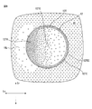
- FIG. 1 is a plan view of a non-woven fabric according to a first embodiment of the present invention
- FIG. 2 is a partial end view taken along line II-II of FIG.
- the non-woven fabric 1 according to the first embodiment extends on the plane of the non-woven fabric 1 defined by the longitudinal direction Lo and the transverse direction Tr, and can be seen in plan view in FIG. And a second surface FS located on the side.
- the non-woven fabric 1 has a base 10 that spreads in a substantially planar shape, and a plurality of protruding from the base 10 in the thickness direction Th to the side of the first surface FF in the first embodiment. It is formed of the convex portion 12.
- Each convex portion 12 includes a convex portion 12T which is separated from the base 10 in the thickness direction Th of the nonwoven fabric 1.
- the convex portion 12T is positioned closer to the top of the convex portion 12 than the middle point of the thickness direction Th between the base 10 and the top of the convex portion 12 most distant from the base 10 in the thickness direction Th. This is a portion of the convex portion 12 that forms a constant surface that faces in the direction in which the convex portion 12 protrudes from the base 10.
- the convex portion 12T is substantially flat.
- the convex surface portion 12T does not have to be a completely flat surface, and may include a constant inclined surface or a curved surface.
- the convex portion 12 has a substantially cylindrical shape with a diameter of about 10 mm in appearance.
- the shape of the convex portion 12 is a shape including a convex portion having a certain area, such as, for example, a truncated cone shape or an elliptical or polygonal columnar shape or a truncated pyramid shape. .
- FIG. 3 is a view for explaining the distribution of fiber density of the convex portion 12T of the convex portion 12 in the nonwoven fabric 1 of FIG.
- FIG. 3 is described paying attention to one convex part 12, and represents the distribution of the fiber density of convex part 12T by the magnitude of the density (number) of "x" mark.
- each convex portion 12T is configured such that the fiber density of the convex portion 12T is biased in the longitudinal direction Lo of the nonwoven fabric 1 in the planar direction of the nonwoven fabric 1. That is, in the convex portion 12T, there is a portion where the fiber density is high on one side in the longitudinal direction Lo and the fiber density is low on the other side in the longitudinal direction Lo on a predetermined line extending in the longitudinal direction Lo.
- each convex portion 12T is formed by a virtual line VL extending in a direction orthogonal to the longitudinal direction Lo of the non-woven fabric 1 in plan view of the non-woven fabric 1.
- VL virtual line extending in a direction orthogonal to the longitudinal direction Lo of the non-woven fabric 1 in plan view of the non-woven fabric 1.
- the “fiber density of the semiconvex portion” refers to the average of the fiber density of the entire semiconvex portions 121T and 122T, but when measuring the fiber density as described later, each semiconvex portion 121T , 122T in a direction perpendicular to the direction in which the fibers are offset, ie in the transverse direction Tr in the case of the first embodiment, in the direction in which the fibers are offset, ie in the case of the first embodiment
- the fiber density is equally divided into three in the longitudinal direction Lo of 1 and the central portions in the transverse direction Tr of these cut surfaces are averaged.
- FIG. 4 is the photograph which image
- the shade of color indicates the high and low of the fiber density.
- darker black in the photo in Fig. 4 indicates that the color of the photographing table is more easily seen through, indicating that the fiber density is lower, and darker white indicates that the color of the photographing table is less transparent, meaning that the fiber density is higher. Do. Also from the photograph shown in FIG.
- the fiber density of the convex portion 12T of the convex portion 12 is biased in the longitudinal direction Lo among the planar directions of the nonwoven fabric 1 in plan view of the nonwoven fabric 1 It can be said that This is because, when the convex portion 12T is observed in FIG. 4, black tends to be dark on one side in the longitudinal direction Lo and white tends to be dark on the other side.
- the number of points FC at which the fibers are cut per 1 mm 2 in the cut surface of the nonwoven fabric 1 is used as an index.
- the magnification is adjusted to about 50 to 100 times and a fixed area (for example, about 2.0 mm 2) Observe the cut surface of) and count the points FC (Fig. 5) where the fibers were cut.
- the cut surface to be observed includes the entire thickness direction Th from the first surface FF to the second surface FS. Then, the number of cutting points is replaced with the number per 1 mm 2 , and the number is used as an index of “fiber density”.
- the fibers used for the non-woven fabric 1 in the first embodiment are fibers with a core-sheath structure, and the material is a high density polyethylene (HDPE) sheath and a polyethylene terephthalate (PET) core.
- HDPE high density polyethylene
- PET polyethylene terephthalate
- Fibers used for non-woven fabrics include natural fibers, regenerated fibers (rayon, acetate, etc.), thermoplastic resin fibers (polyethylene, polypropylene, polybutylene, ethylene-vinyl acetate copolymer, ethylene-ethyl acrylate copolymer, Ethylene-acrylic acid copolymers, polyolefins such as ionomer resins, polyethylene terephthalate, polyesters such as polybutylene terephthalate, polytrimethylene terephthalate, polylactic acid, polyamides such as nylon, etc. or surface-modified products thereof Among these, it is preferable that they are a thermoplastic resin fiber or its surface modification body.
- these fibers include core-sheath fibers, composite fibers such as side-by-side fibers, island / sea fibers, hollow fibers, flat fibers, atypical fibers such as Y-type and C-type fibers, latent fibers It may be a crimped or three-dimensional crimped crimped crimped fiber, a water stream, or a split fiber split by physical load such as heat or embossing.
- These fibers may be hydrophilic fibers or hydrophobic fibers. However, in the case of using a hydrophobic fiber, processing such as separately applying a hydrophilic oil to the fiber is required.
- the convex part 12 is arrange
- the first direction D1 is the same as the transverse direction Tr
- the second direction D2 is a direction inclined 60 ° from the first direction D1.
- the base 10 and the convex part 12 are arrange
- the non-woven fabric 1 when used as a top sheet of an absorbent article such as disposable diapers or a sanitary napkin, the bodily fluid excreted on the non-woven fabric 1 can be absorbed when the first surface FF is used as the surface. It is possible to arrange the base 10 which penetrates into the inside where the absorbent or the like of the article is located, and the convex part 12 which penetrates the body fluid in a desired direction, in a suitable distribution.
- the convex portions 12 adjacent to the first direction D1 and the second direction D2 are intermittently provided to separate the base 10. ing.
- the body fluid excreted on the first surface FF can be made to permeate in the direction in which the fiber density is biased, and transferred from the convex portion 12T of the convex portion 12 to the adjacent base portion 10.
- the liquid can be efficiently permeated from the base 10 into the interior of the absorbent article.
- the convex portions 12T are configured such that the fiber density of the convex portions 12T is biased in the longitudinal direction Lo among the planar directions of the nonwoven fabric 1. Therefore, the liquid absorbed by the fibers forming the convex portion 12 easily penetrates from the low fiber density to the high fiber density by capillary action, and thus tends to move to the high fiber density side in the longitudinal direction Lo. Therefore, by disposing the non-woven fabric so that the side with the higher fiber density is disposed in the direction in which the liquid is to be infiltrated, the absorbed liquid can be infiltrated in the desired direction.
- the liquid can be permeated in the desired direction does not mean that the liquid penetrates only in the desired direction, but the amount of liquid that penetrates in the desired direction is increased. It should be noted that the meaning of
- the fiber density of the convex portion 12T is biased in the longitudinal direction Lo in the nonwoven fabric 1 according to the first embodiment, but may be biased in any direction in the planar direction of the nonwoven fabric 1. That is, the convex portion 12T may be configured so that the fiber density of the convex portion 12T is biased in a predetermined direction in the plane direction of the nonwoven fabric 1. Then, the liquid can be made to penetrate in a desired direction by arranging the side with high fiber density to be in the direction in which the liquid is desired to permeate.
- FIG. 3 demonstrated the fiber distribution of convex part 12T of the one convex part 12, in the nonwoven fabric 1 which concerns on 1st embodiment, convex part 12T of each convex part 12 is the same as that of FIG. It has a fiber distribution.
- the fiber density of the convex portions 12T of all the convex portions 12 need not be uneven, and the nonwoven fabric 1 in which the fiber density of the convex portions 12T of the convex portions 12 is uneven for at least a part of the convex portions 12 It can be said that it is the nonwoven fabric of the range of the invention. This is because there is no change in exerting the effect of the nonwoven fabric 1 of the present invention that the liquid absorbed in the nonwoven fabric 1 can permeate in the desired direction.
- the degree of the deviation of the fiber density of the convex portion 12T may be a degree that allows the liquid absorbed in the non-woven fabric 1 to penetrate in a desired direction.
- the convex portion 12 is linear along the first direction D1 and the second direction D2 inclined 60 ° from the first direction D1. Are located in In another embodiment, the second direction D2 is inclined at an angle other than 60 ° from the first direction D1. In yet another embodiment, the protrusions 12 are disposed linearly along only one direction. In the other embodiment, the convex portion 12 is not disposed along any direction but disposed at an arbitrary position.
- the base 10 and the convex part 12 are arrange
- the distance between the protrusions 12 is not constant.
- the convex portion 12 is linearly disposed in either the first direction D1 or the second direction D2, and in still another embodiment, disposed along any direction. It is not set up and is irregularly placed.
- the nonwoven fabric 1 according to the second embodiment of the present invention will be described with reference to FIG.
- the second embodiment will be mainly described in terms of differences from the first embodiment.
- FIG. 6 is a diagram for explaining the fiber density distribution of the convex portion 12T of the convex portion 12 in the nonwoven fabric 1 according to the second embodiment.
- the edge 12TE of the convex portion 12T has a higher fiber density than the central portion 12TC of the convex portion 12T.
- the rigidity of the edge 12TE becomes high, whereby the shape of the convex portion 12 is maintained even when an external force is applied to the convex portion 12 can do.
- the nonwoven fabric 1 according to the second embodiment is preferable also in appearance (appearance) because the shape of the convex portion 12 of the nonwoven fabric 1 at the time of production can be maintained even after packaging and opening.
- the edge 12TE is a region of the convex portion 12T having a constant width in the direction of the central portion 12TC along the edge 12TEE of the convex portion 12T to the extent that the fiber density can be confirmed.
- the central portion 12TC is a portion farther from the edge 12TEE than the edge 12TE.
- the width of the edge 12TE is about 1 mm with respect to the convex part 12T having a diameter of about 10 mm, that is, about 10% of the diameter (or the length of the convex part 12T).
- the fiber density of the convex surface portion 12T is the longitudinal direction Lo of the nonwoven fabric 1 among the planar directions of the nonwoven fabric 1. It is configured to be biased. That is, in the second embodiment, on a line extending in the predetermined longitudinal direction Lo at the central portion 12TC of the convex portion 12T, the fiber density is high at a position on one side in the longitudinal direction Lo and the other side in the longitudinal direction Lo There is a portion with low fiber density in the portion.
- the nonwoven fabric 1 according to the third embodiment of the present invention will be described with reference to FIG. 7.
- the third embodiment will be mainly described in terms of differences from the first embodiment.
- FIG. 7 is a view for explaining the fiber density distribution of the convex portion 12T of the convex portion 12 and the base portion 10 located around the convex portion 12 in the nonwoven fabric 1 according to the third embodiment.
- the fiber density of the fibers constituting the convex portion 12T of the convex portion 12, which is one end of the convex portion 12T in the longitudinal direction Lo in plan view of the nonwoven fabric 1
- the fiber density is lower than the other portions of the base 10. That is, in the base 10, the fiber density becomes lower as the fiber density of the convex portion 12 approaches the portion 12TH where the fiber density of the convex portion 12 is higher.
- the base 10 there will be a portion where the fiber density is lower than the other portions.
- the low fiber density portion 10L of the base 10 located at the position of the base 10 it is possible to rapidly permeate.
- the body fluid excreted on the non-woven fabric 1 can be rapidly transferred to the inside of the absorbent article provided with an absorbent or the like, which is preferable.
- the nonwoven fabric 1 according to the fourth embodiment of the present invention will be described with reference to FIG.
- the fourth embodiment will be mainly described in terms of differences from the third embodiment.
- FIG. 8 is a view for explaining the fiber density distribution of the convex portion 12T of the convex portion 12 and the base portion 10 located around the convex portion 12 in the nonwoven fabric 1 according to the fourth embodiment.
- the edge 12TE of the convex portion 12T is the center of the convex portion 12T.
- Fiber density is higher than 12 TC. That is, the nonwoven fabric 1 which concerns on 4th embodiment is a nonwoven fabric which has both the effect of the nonwoven fabric 1 which concerns on 2nd and 3rd embodiment.
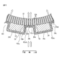
- FIG. 9 is a schematic view showing an outline of a production facility 3 for producing the non-woven fabric 1 according to the embodiment of the present invention
- FIG. 10 is an enlarged view of a portion X in FIG.
- the manufacturing equipment 3 forms a carding machine 20 for opening the fiber F1 and adjusting the fabric weight, a suction drum 22 and an air jet nozzle 26 for forming the fiber F2 so as to be in the shape of the nonwoven fabric 1, and a fiber F3.
- the heat processing machine 28 heat-processes the fiber F3 so that fixed shape may be fixed.
- the fibers F1 to F3 and the non-woven fabric 1 described later are transported in the direction of the arrow MD, and the transport direction MD coincides with the longitudinal direction Lo of the non-woven fabric 1.
- the method of producing the non-woven fabric 1 will be briefly described. First, the fiber F1 is opened by the carding machine 20 and the coating weight is adjusted, and the opened fiber F2 is supplied to the suction drum 22. Subsequently, warm air is blown by the air jet nozzle 26 while suctioning and moving the fiber F2 on the outer peripheral surface of the suction drum 22 provided with the pattern plate 24 so that the shape of the nonwoven fabric 1 according to the above embodiment is obtained. Form the fiber F2. And the non-woven fabric 1 is completed by heat-treating the fiber F3 after shaping in the heat treatment machine 28 and fixing the shape of the fiber F3 shaped in the previous step.
- the method of manufacturing the non-woven fabric 1 will now be described in detail.
- the opened fiber F ⁇ b> 1 is supplied to the carding machine 20.
- the fiber F1 is further opened, and the basis weight (weight) of the fiber F1 is adjusted to a desired value.
- the fiber F2 which has passed through the card machine 20 is supplied to the suction drum 22.
- the inside of the suction drum 22 is hollow, and the inside of the suction drum 22 is under negative pressure by suction of air by suction means such as a blower.
- a large number of suction holes 22t are provided on the outer peripheral surface of the suction drum 22 so that outside air can be sucked.
- the diameter of the suction hole of the suction drum 22 is set small so as not to suction the fiber F2 into the suction drum 22.
- the pattern plate 24 is an apertured plate in which through holes 24 t having a shape complementary to the projections 12 of the nonwoven fabric 1 are provided with the distribution of the projections 12.
- the suction holes of the suction drum 22 exposed in the through holes 24 t of the pattern plate 24 suck the fibers F 2 supplied onto the pattern plate 24.
- the difference in position in the thickness direction Th of the nonwoven fabric 1 between the base 10 and the convex portion 12T of the convex portion 12 in the first surface FF is substantially equal to the thickness of the pattern plate 24.
- the suction drum 22 has an area AS from the point SS where the fiber F2 is delivered from the upstream belt conveyor UB to the point SE where the fiber F2 is delivered to the downstream belt conveyor DB on the outer peripheral surface.
- the fiber F2 is designed to suck at the other area, and is configured not to suck at the other area AN. This is to improve the efficiency of the suction operation by the suction drum 22.
- the fibers F 2 sucked to the outer peripheral surface of the suction drum 22 are blown with warm air by the air jet nozzle 26.
- the air jet nozzle 26 has a mechanism that ejects a predetermined amount of warm air uniformly with a uniform width in the width direction.
- warm air is blown substantially uniformly over the entire width of the laminate formed from the fiber F2.
- the fibers F2 can be shaped so as to have the shape of the nonwoven fabric 1 according to the above-described embodiment by the suction action and the spray action by the suction drum 22 and the air jet nozzle 26.
- the temperature of the hot air blown from the air jet nozzle 26 is higher than the melting point of the fiber F2, but is adjusted so as not to be too high in order to avoid the nonwoven fabric 1 becoming excessively hardened after completion. There is. Also, the wind speed of the warm air is determined so as to shape the fiber F2 into a desired shape. Generally, the temperature and the wind speed of the warm air from the air jet nozzle 26 vary depending on the material and weight of the fiber used, the shape of the non-woven fabric 1 after completion, and the like. Is preferred. For example, the temperature of the warm air blown from the air jet nozzle 26 is preferably 80 ° C. to 400 ° C., and the wind speed thereof is preferably 10 to 200 m / sec.
- the temperature of the warm air blown from the air jet nozzle 26 is 180 ° C., and the wind speed thereof is 38.9 m / sec.
- the wind speed thereof is 38.9 m / sec.
- the surface of the laminate formed of the fibers F2 facing the suction drum 22 and the pattern plate 24 is the first surface FF of the nonwoven fabric 1 and faces the air jet nozzle 26.
- the surface of the laminate is the second surface FS of the nonwoven fabric 1.
- the fiber F2 When the fiber F2 is blown by the air jet nozzle 26, it is blown off and moves around it. As a result, the amount of fibers in the sprayed part will be reduced and thus the fiber density of the sprayed part will be lower.
- the air jet nozzle 26 since the air jet nozzle 26 is stationary, the fiber F2 located in the through hole 24t of the pattern plate 24 is finally blown by the warm air at the portion F2tu located on the upstream side in the transport direction MD. The attachment reduces the fiber density. Thereafter, the fiber F2 moved by the blowing action by the air jet nozzle 26 is fixed at the position after the movement by the suction action of the suction drum 22.
- the convex portion 12T is a direction in which the fiber density of the convex portion 12T is a predetermined direction, in the above-mentioned embodiment, the direction of It is configured to be biased in the longitudinal direction Lo.
- portion F2su of the fibers F2 located on the outer surface 24s located between the through holes 24t of the pattern plate 24 and located upstream of the transport direction MD that is, when the warm air is blown to the portion F2su, the fiber F2 is blown off and moves around. At this time, the fiber F2 also moves in the through hole 24t. Thereafter, warm air is blown to a portion F2tu of the fiber F2 in the through hole 24t on the upstream side in the transport direction of the fiber F2, but once the fiber F2 moves into the through hole 24t, the inside of the through hole 24t Since the fiber F2 does not return from the to the outer surface 24s, the fiber density of the portion F2su is low.
- the fiber density of the portion F2tu on the upstream side in the transport direction of the fiber F2 in the through hole 24t is high.
- the fiber density of the base 10 decreases as the fiber density of the convex portion 12 approaches the portion 12 TH where the fiber density of the convex portion 12 is high.
- the corner portion Co is a position corresponding to the edge portion 12 TE of the convex portion 12 in the nonwoven fabric 1.
- the edge 12TE of the projection 12 is the central portion 12TC of the projection.
- the fiber density is higher than that.
- the shape of the convex portion 12 is determined by the shape of the through hole 24t of the pattern plate 24, the temperature of the warm air blown from the air jet nozzle 26, the wind speed, and the like.
- the fibers F3 shaped by the suction and spraying action are then transferred to the heat treatment machine.
- the fibers F3 are heat treated in the heat treatment machine 28 and the shape shaped in the previous step is fixed.
- the fiber F3 is heat-treated for a long time with warm air at a relatively low temperature and a low temperature relatively to the melting point of the fiber, thereby fixing the shape of the fiber F3 formed in the previous step It is possible to make the nonwoven fabric 1 flexible.
- the temperature of the warm air in the heat treatment machine 28, the wind speed, the time of the heat treatment, etc. vary depending on the material of the fibers used, the coating weight, etc. However, it is preferable to determine the optimum temperature and wind speed by experiments, for example.
- the nonwoven fabric 1 is completed.
- the finished nonwoven fabric 1 is cut into a desired size and used.
- the manufacturing method of the nonwoven fabric 1 according to the fourth embodiment has been described, but by appropriately changing the shape of the pattern plate 24, the temperature of the warm air blown from the air jet nozzle 26, etc.
- the nonwoven fabric 1 according to the first to third aspects can be manufactured.
- the liquid diffusion distance test was performed with the nonwoven fabric in which various conditions were set.
- the liquid diffusion distance test is a test to confirm that the liquid absorbed by the non-woven fabric penetrates in a directional manner.
- Examples 1 to 3 The non-woven fabrics according to Examples 1 to 3 are produced by the above-mentioned production method.
- the temperature and the wind speed of the warm air blown from the air jet nozzle 26 when manufacturing these non-woven fabrics, and the temperature and the wind speed of the heat treatment in the heat treatment machine 28 are shown in Table 1 described later. Further, in these non-woven fabrics, the deviation of the fiber density of the convex part of the convex part was measured by the above-mentioned measuring method of the fiber density around the two measurement points PH and PL shown in FIG.
- One measurement point PH is a middle point between the center point C of the convex portion 12T in plan view of the nonwoven fabric 1 and the edge 12TEE located on the side where the fiber density is high along the longitudinal direction Lo from the center point C.
- the other measurement point PL is a midpoint between the center point C of the convex portion 12T and the edge 12TEE located on the side where the fiber density is low along the longitudinal direction Lo from the center point C.
- the test method of the test performed in the present embodiment will be described.
- a sample of the non-woven fabric according to the example and the comparative example cut to a width of 150 mm and a length of 300 mm was placed on a stainless plate of 250 mm width and 450 mm length, and 20 cc at the center of one convex portion
- the artificial artificial urine was done by dropping it in 2.5 seconds.
- the longitudinal direction of the sample is the direction in which the fiber density of the fibers constituting the convex portion of the convex portion is uneven, and the direction along which the fiber density of the convex portion is high is taken as the DH direction.
- the direction in which the fiber density of the part was low was taken as the DL direction.
- the artificial urine used in the liquid diffusion distance test was prepared by dissolving 200 g of urea, 80 g of sodium chloride, 8 g of magnesium sulfate, 3 g of calcium chloride and about 1 g of pigment (Blue No. 1) in 10 L of ion-exchanged water .
- Table 1 is shown below. Table 1 shows the results of the fabric weight, thickness, preparation conditions, each measurement point PH, the fiber density of the convex portion around PL and the liquid diffusion distance test around each of the nonwoven fabrics of Examples 1 to 3 and Comparative Example. In addition, "thickness" of Table 1 is an average value of the thickness measured 3 times under the pressure of 3 gf / cm2, and in the nonwoven fabric concerning Example 1-3, the thickness of the convex part was measured. .
- the edge 12TE of the convex portion 12T has a higher fiber density than the central portion 12TC of the convex portion 12T
- the third embodiment As the form, the base 10 has a lower fiber density as the fiber density of the convex portion 12 approaches the high portion 12 TH around the convex portion 12.
- the present invention is defined as follows.
- a non-woven fabric formed of a base extending in a planar shape and a plurality of convex portions protruding in the thickness direction from the base, Each said convex part has a convex part, and Each of the convex portions is configured such that the fiber density of the convex portions is biased in a predetermined direction of the planar direction of the nonwoven fabric.
- Non-woven fabric formed of a base extending in a planar shape and a plurality of convex portions protruding in the thickness direction from the base, Each said convex part has a convex part, and Each of the convex portions is configured such that the fiber density of the convex portions is biased in a predetermined direction of the planar direction of the nonwoven fabric.
- an edge portion of the convex portion has a higher fiber density than a central portion of the convex portion.
- the convex portion is disposed along a first direction and a second direction different from the first direction.
- the nonwoven fabric according to any one of (1) to (4).
- the convex portions are provided at equal intervals apart from the base in the first direction and the second direction.
- the predetermined direction coincides with the first direction or the second direction.
- the predetermined direction coincides with the transport direction when manufacturing the non-woven fabric, The nonwoven fabric according to any one of (1) to (7).
- Non-woven fabric 10 Base 12 Convex part 12 T Convex part
Landscapes
- Engineering & Computer Science (AREA)
- Textile Engineering (AREA)
- Mechanical Engineering (AREA)
- Nonwoven Fabrics (AREA)
- Woven Fabrics (AREA)
Abstract
Description
平面状に拡がる基部と、前記基部から厚さ方向に突出する複数の凸部とから形成されている不織布であって、
それぞれの前記凸部は凸面部を有し、
それぞれの前記凸面部は、前記凸面部の繊維密度が前記不織布の平面方向のうち所定の方向に偏るように構成されている、
不織布を提供することができる。 In order to solve the above-mentioned problems, according to the present invention,
A non-woven fabric formed of a base extending in a planar manner and a plurality of projections projecting in the thickness direction from the base,
Each said convex part has a convex part, and
Each of the convex portions is configured such that the fiber density of the convex portions is biased in a predetermined direction of the planar direction of the nonwoven fabric.
Nonwoven fabrics can be provided.
これより、図1~図5を参照しつつ、本発明の第一の実施形態に係る不織布1について説明する。 (First embodiment)
The nonwoven fabric 1 according to the first embodiment of the present invention will be described with reference to FIGS. 1 to 5.
これより、図6を参照しつつ本発明の第二の実施形態に係る不織布1を説明する。第二の実施形態については、第一の実施形態と異なる点について主に説明する。 Second Embodiment
From this, the nonwoven fabric 1 according to the second embodiment of the present invention will be described with reference to FIG. The second embodiment will be mainly described in terms of differences from the first embodiment.
これより、図7を参照しつつ、本発明の第三の実施形態に係る不織布1を説明する。第三の実施形態については、第一の実施形態と異なる点について主に説明する。 Third Embodiment
The nonwoven fabric 1 according to the third embodiment of the present invention will be described with reference to FIG. 7. The third embodiment will be mainly described in terms of differences from the first embodiment.
これより、図8を参照しつつ本発明の第四の実施形態に係る不織布1を説明する。第四の実施形態については、第三の実施形態と異なる点について主に説明する。 Fourth Embodiment
From this, the nonwoven fabric 1 according to the fourth embodiment of the present invention will be described with reference to FIG. The fourth embodiment will be mainly described in terms of differences from the third embodiment.
これより、第四の実施形態に係る不織布1の製造方法を説明する。図9は、本発明の実施形態に係る不織布1を製造するための製造設備3の概要を示す概略図であり、図10は図9のX部拡大図である。製造設備3は、繊維F1を開繊しかつ目付けを調整するカード機20と、不織布1の形状になるように繊維F2を賦形するサクションドラム22及びエアジェットノズル26と、繊維F3に賦形された形状を定着させるように繊維F3を熱処理する熱処理機28を備える。なお、図9において、後述する繊維F1~F3及び不織布1は矢印MDの方向に搬送され、この搬送方向MDは不織布1の長手方向Loと一致する。 (Method of manufacturing non-woven fabric)
From this, the manufacturing method of nonwoven fabric 1 concerning a fourth embodiment is explained. FIG. 9 is a schematic view showing an outline of a production facility 3 for producing the non-woven fabric 1 according to the embodiment of the present invention, and FIG. 10 is an enlarged view of a portion X in FIG. The manufacturing equipment 3 forms a carding
実施例1~3に係る不織布は、上述の製造方法によって製造されたものである。これらの不織布を製造するときのエアジェットノズル26から吹付けられる温風の温度及び風速と、熱処理機28内における熱処理の温度及び風速は、後述する表1に示されている。また、これらの不織布における、凸部の凸面部の繊維密度の偏りは、図11に示される2つの測定点PH、PLの周囲で、上述の繊維密度の測定方法により測定された。一方の測定点PHは、不織布1の平面視における凸面部12Tの中心点Cと、中心点Cから長手方向Loに沿って繊維密度が高い側に位置する端縁12TEEとの中点である。そして、他方の測定点PLは、凸面部12Tの中心点Cと、中心点Cから長手方向Loに沿って繊維密度が低い側に位置する端縁12TEEとの中点である。これらの測定点で測定された繊維密度の差が大きいと、より凸面部の繊維密度が偏っているということができる。後述する表1を参照すると、実施例1よりも実施例2に係る不織布の凸面部の繊維密度が偏っている。そして実施例2よりも実施例3に係る不織布の凸面部の繊維密度が偏っている。 (Examples 1 to 3)
The non-woven fabrics according to Examples 1 to 3 are produced by the above-mentioned production method. The temperature and the wind speed of the warm air blown from the
比較例に係る不織布は、カード機で開繊された繊維が、サクションドラムによって吸引されることなく、かつエアジェットノズルによって温風を吹付けられることなく、熱処理機で繊維密度が均等になるように平面状に形成されたものである。このときの、熱処理機内における熱処理の温度及び風速は、後述する表1に示されている。 (Comparative example)
In the non-woven fabric according to the comparative example, the fibers opened by the carding machine are not sucked by the suction drum and the hot air is not blown by the air jet nozzle, so that the fiber density becomes uniform by the heat treatment machine In a plane. The temperature and the wind speed of the heat treatment in the heat treatment machine at this time are shown in Table 1 described later.

それぞれの前記凸部は凸面部を有し、
それぞれの前記凸面部は、前記凸面部の繊維密度が前記不織布の平面方向のうち所定の方向に偏るように構成されている、
不織布。 (1) A non-woven fabric formed of a base extending in a planar shape and a plurality of convex portions protruding in the thickness direction from the base,
Each said convex part has a convex part, and
Each of the convex portions is configured such that the fiber density of the convex portions is biased in a predetermined direction of the planar direction of the nonwoven fabric.
Non-woven fabric.
(1)に記載の不織布。 (2) In each of the convex portions, an edge portion of the convex portion has a higher fiber density than a central portion of the convex portion.
The nonwoven fabric as described in (1).
(1)又は(2)に記載の不織布。 (3) The fiber density of the base decreases as the fiber density of the convex portion approaches the portion around the convex portion,
The nonwoven fabric as described in (1) or (2).
(1)~(3)のいずれか1つに記載の不織布。 (4) When each of the convex portions is bisected into two semi-convex portions so as to have the same area by an imaginary line extending in a direction orthogonal to the predetermined direction in a plan view of the nonwoven fabric, The fiber density of the semiconvex part is higher than the fiber density of the other semiconvex part,
The nonwoven fabric according to any one of (1) to (3).
(1)~(4)のいずれか1つに記載の不織布。 (5) The convex portion is disposed along a first direction and a second direction different from the first direction.
The nonwoven fabric according to any one of (1) to (4).
(5)に記載の不織布。 (6) The convex portions are provided at equal intervals apart from the base in the first direction and the second direction.
The nonwoven fabric as described in (5).
(5)又は(6)に記載の不織布。 (7) The predetermined direction coincides with the first direction or the second direction.
The nonwoven fabric as described in (5) or (6).
(1)~(7)のいずれか1つに記載の不織布。 (8) The predetermined direction coincides with the transport direction when manufacturing the non-woven fabric,
The nonwoven fabric according to any one of (1) to (7).
10 基部
12 凸部
12T 凸面部 1
Claims (8)
- 平面状に拡がる基部と、前記基部から厚さ方向に突出する複数の凸部とから形成されている不織布であって、
それぞれの前記凸部は凸面部を有し、
それぞれの前記凸面部は、前記凸面部の繊維密度が前記不織布の平面方向のうち所定の方向に偏るように構成されている、
不織布。 A non-woven fabric formed of a base extending in a planar manner and a plurality of projections projecting in the thickness direction from the base,
Each said convex part has a convex part, and
Each of the convex portions is configured such that the fiber density of the convex portions is biased in a predetermined direction of the planar direction of the nonwoven fabric.
Non-woven fabric. - それぞれの前記凸部において、前記凸面部の縁部は、前記凸面部の中央部よりも繊維密度が高い、
請求項1に記載の不織布。 In each of the convex portions, the edge of the convex portion has a higher fiber density than the central portion of the convex portion.
The nonwoven fabric according to claim 1. - 前記基部は、前記凸部の周囲において、凸部の繊維密度が高い部分に近づくにつれて、繊維密度が低くなる、
請求項1又は2に記載の不織布。 The fiber density of the base portion decreases as the fiber density of the convex portion approaches the portion around the convex portion.
The nonwoven fabric according to claim 1 or 2. - それぞれの前記凸面部を、前記不織布の平面視において前記所定の方向に直交する方向に延びる仮想線によって同じ面積になるように2つの半凸面部に二等分したときに、一方の前記半凸面部の繊維密度が、他方の前記半凸面部の繊維密度よりも高い、
請求項1~3のいずれか1項に記載の不織布。 One of the half convex surfaces when each of the convex surface portions is bisected into two semi convex surface portions so as to have the same area by an imaginary line extending in a direction orthogonal to the predetermined direction in a plan view of the nonwoven fabric The fiber density of one section is higher than the fiber density of the other half convex section,
The nonwoven fabric according to any one of claims 1 to 3. - 前記凸部が、第一の方向及び前記第一の方向と異なる第二の方向に沿って配設されている、
請求項1~4のいずれか1項に記載の不織布。 The convex portion is disposed along a first direction and a second direction different from the first direction.
The nonwoven fabric according to any one of claims 1 to 4. - 前記凸部は、前記第一の方向及び前記第二の方向に前記基部を隔てて等間隔に設けられている、
請求項5に記載の不織布。 The protrusions are provided at equal intervals across the base in the first direction and the second direction.
The nonwoven fabric according to claim 5. - 前記所定の方向は、前記第一の方向又は前記第二の方向と一致する、
請求項5又は6に記載の不織布。 The predetermined direction coincides with the first direction or the second direction.
The nonwoven fabric according to claim 5 or 6. - 前記所定の方向は、前記不織布を製造するときの搬送方向と一致する、
請求項1~7のいずれか1項に記載の不織布。 The predetermined direction coincides with the transport direction when manufacturing the non-woven fabric,
The nonwoven fabric according to any one of claims 1 to 7.
Priority Applications (7)
| Application Number | Priority Date | Filing Date | Title |
|---|---|---|---|
| US15/321,780 US20170226672A1 (en) | 2014-06-26 | 2015-06-25 | Non-woven fabric |
| KR1020167035643A KR102294225B1 (en) | 2014-06-26 | 2015-06-25 | Non-woven fabric |
| BR112016029946A BR112016029946A2 (en) | 2014-06-26 | 2015-06-25 | nonwoven |
| CN201580034409.8A CN106661791B (en) | 2014-06-26 | 2015-06-25 | Non-woven fabric |
| EP15811703.6A EP3162939A4 (en) | 2014-06-26 | 2015-06-25 | Non-woven fabric |
| AU2015281112A AU2015281112B2 (en) | 2014-06-26 | 2015-06-25 | Non-woven fabric |
| PH12016502606A PH12016502606A1 (en) | 2014-06-26 | 2016-12-23 | Non-woven fabric |
Applications Claiming Priority (2)
| Application Number | Priority Date | Filing Date | Title |
|---|---|---|---|
| JP2014131732A JP5931131B2 (en) | 2014-06-26 | 2014-06-26 | Non-woven |
| JP2014-131732 | 2014-06-26 |
Publications (1)
| Publication Number | Publication Date |
|---|---|
| WO2015199179A1 true WO2015199179A1 (en) | 2015-12-30 |
Family
ID=54938256
Family Applications (1)
| Application Number | Title | Priority Date | Filing Date |
|---|---|---|---|
| PCT/JP2015/068353 WO2015199179A1 (en) | 2014-06-26 | 2015-06-25 | Non-woven fabric |
Country Status (9)
| Country | Link |
|---|---|
| US (1) | US20170226672A1 (en) |
| EP (1) | EP3162939A4 (en) |
| JP (1) | JP5931131B2 (en) |
| KR (1) | KR102294225B1 (en) |
| CN (1) | CN106661791B (en) |
| AU (1) | AU2015281112B2 (en) |
| BR (1) | BR112016029946A2 (en) |
| PH (1) | PH12016502606A1 (en) |
| WO (1) | WO2015199179A1 (en) |
Families Citing this family (3)
| Publication number | Priority date | Publication date | Assignee | Title |
|---|---|---|---|---|
| GB2582405B (en) * | 2017-08-31 | 2021-03-31 | Kao Corp | Nonwoven fabric |
| JP6623206B2 (en) * | 2017-12-26 | 2019-12-18 | 花王株式会社 | Nonwoven manufacturing method |
| BR112021009321A2 (en) * | 2018-11-30 | 2021-08-17 | Kimberly-Clark Worldwide, Inc. | non-woven material |
Citations (6)
| Publication number | Priority date | Publication date | Assignee | Title |
|---|---|---|---|---|
| US20040106346A1 (en) * | 2002-11-29 | 2004-06-03 | Zafiroglu Dimitri Peter | Textured composite material |
| JP2008161302A (en) * | 2006-12-27 | 2008-07-17 | Kao Corp | Surface sheet for absorptive article and its manufacturing method |
| JP2009061026A (en) * | 2007-09-05 | 2009-03-26 | Kao Corp | Absorbent article |
| JP2009233099A (en) * | 2008-03-27 | 2009-10-15 | Daio Paper Corp | Absorbent article |
| JP2012143543A (en) * | 2010-12-20 | 2012-08-02 | Kao Corp | Absorbent article |
| JP2014083228A (en) * | 2012-10-24 | 2014-05-12 | Kao Corp | Absorbent article |
Family Cites Families (9)
| Publication number | Priority date | Publication date | Assignee | Title |
|---|---|---|---|---|
| MY151019A (en) | 2006-06-23 | 2014-03-31 | Uni Charm Corp | Absorbent article |
| CN101448990B (en) * | 2006-06-23 | 2011-12-07 | 尤妮佳股份有限公司 | Nonwoven fabric |
| JP5154048B2 (en) * | 2006-06-23 | 2013-02-27 | ユニ・チャーム株式会社 | Non-woven |
| DE602006010351D1 (en) * | 2006-06-26 | 2009-12-24 | Marco Maranghi | Multilayer and multicomponent nonwoven material with different fiber density and process for its production |
| CN101790606B (en) * | 2007-08-28 | 2012-09-05 | 花王株式会社 | Shaped sheet and absorbent article utilizing the same |
| JP5421720B2 (en) * | 2009-10-09 | 2014-02-19 | ユニ・チャーム株式会社 | Non-woven |
| RU2642033C1 (en) * | 2010-12-24 | 2018-01-23 | Као Корпорейшн | Non-woven material and absorbing product using it |
| JP5921866B2 (en) | 2010-12-24 | 2016-05-24 | 花王株式会社 | Non-woven |
| JP5717602B2 (en) * | 2011-09-30 | 2015-05-13 | ユニ・チャーム株式会社 | Laminated nonwoven fabric and method for producing the laminated nonwoven fabric |
-
2014
- 2014-06-26 JP JP2014131732A patent/JP5931131B2/en active Active
-
2015
- 2015-06-25 EP EP15811703.6A patent/EP3162939A4/en not_active Withdrawn
- 2015-06-25 US US15/321,780 patent/US20170226672A1/en not_active Abandoned
- 2015-06-25 BR BR112016029946A patent/BR112016029946A2/en not_active IP Right Cessation
- 2015-06-25 CN CN201580034409.8A patent/CN106661791B/en active Active
- 2015-06-25 WO PCT/JP2015/068353 patent/WO2015199179A1/en active Application Filing
- 2015-06-25 KR KR1020167035643A patent/KR102294225B1/en active IP Right Grant
- 2015-06-25 AU AU2015281112A patent/AU2015281112B2/en not_active Ceased
-
2016
- 2016-12-23 PH PH12016502606A patent/PH12016502606A1/en unknown
Patent Citations (6)
| Publication number | Priority date | Publication date | Assignee | Title |
|---|---|---|---|---|
| US20040106346A1 (en) * | 2002-11-29 | 2004-06-03 | Zafiroglu Dimitri Peter | Textured composite material |
| JP2008161302A (en) * | 2006-12-27 | 2008-07-17 | Kao Corp | Surface sheet for absorptive article and its manufacturing method |
| JP2009061026A (en) * | 2007-09-05 | 2009-03-26 | Kao Corp | Absorbent article |
| JP2009233099A (en) * | 2008-03-27 | 2009-10-15 | Daio Paper Corp | Absorbent article |
| JP2012143543A (en) * | 2010-12-20 | 2012-08-02 | Kao Corp | Absorbent article |
| JP2014083228A (en) * | 2012-10-24 | 2014-05-12 | Kao Corp | Absorbent article |
Non-Patent Citations (1)
| Title |
|---|
| See also references of EP3162939A4 * |
Also Published As
| Publication number | Publication date |
|---|---|
| EP3162939A1 (en) | 2017-05-03 |
| PH12016502606A1 (en) | 2017-04-24 |
| KR102294225B1 (en) | 2021-08-27 |
| JP2016008368A (en) | 2016-01-18 |
| AU2015281112A1 (en) | 2017-02-16 |
| CN106661791A (en) | 2017-05-10 |
| JP5931131B2 (en) | 2016-06-08 |
| KR20170021791A (en) | 2017-02-28 |
| BR112016029946A2 (en) | 2017-08-22 |
| EP3162939A4 (en) | 2017-05-17 |
| US20170226672A1 (en) | 2017-08-10 |
| AU2015281112B2 (en) | 2018-05-10 |
| CN106661791B (en) | 2019-12-17 |
Similar Documents
| Publication | Publication Date | Title |
|---|---|---|
| US10966880B2 (en) | Methods and tooling for making three-dimensional substrates for absorbent articles | |
| KR102172310B1 (en) | Nonwoven fabric | |
| KR102082289B1 (en) | Three-dimensional sheet material and absorbent articles including such material | |
| JP5538943B2 (en) | Non-woven sheet and method for producing the same | |
| TWI327181B (en) | ||
| US20100191207A1 (en) | Nonwoven fabric and method for making the same | |
| EP1110521A1 (en) | Method for manufacturing particle deposited body | |
| US10166154B2 (en) | Shaped non-woven fabric for absorbent article, absorbent article including said shaped non-woven fabric, and method for manufacturing said shaped non-woven fabric | |
| IL123499A (en) | Method of forming apertured films, resultant films and applications thereof | |
| JP2009185408A (en) | Nonwoven fabric | |
| WO2015199179A1 (en) | Non-woven fabric | |
| US10285873B2 (en) | Absorbent article demonstrating controlled deformation and longitudinal fluid distribution | |
| AU2015285725A1 (en) | Absorbent body for body fluid-absorbing articles | |
| JP5885783B2 (en) | Non-woven | |
| JP2016060995A (en) | Ridged and grooved nonwoven fabric | |
| US9968496B2 (en) | Absorbent article demonstrating controlled deformation and longitudinal fluid distribution | |
| US9999554B2 (en) | Absorbent article demonstrating controlled deformation and longitudinal fluid distribution | |
| US10307308B2 (en) | Absorbent article demonstrating controlled deformation and longitudinal fluid distribution | |
| US10265224B2 (en) | Absorbent article demonstrating controlled deformation and longitudinal fluid distribution | |
| US20160089278A1 (en) | Absorbent article demonstrating controlled deformation and longitudinal fluid distribution | |
| WO2021172476A1 (en) | Nonwoven fabric, nonwoven fabric product and absorbent article each provided with same, and method for producing said nonwoven fabric product | |
| JPH04300545A (en) | Surface material for sanitary goods and production thereof | |
| AU5506700A (en) | Apertured film having improved fluid distribution properties, method of forming same, and absorbent products incorporating same | |
| MXPA98001711A (en) | Movie with openings that have improved properties of fluid distribution, method to form the same and absorbent products that incorporate the |
Legal Events
| Date | Code | Title | Description |
|---|---|---|---|
| 121 | Ep: the epo has been informed by wipo that ep was designated in this application |
Ref document number: 15811703 Country of ref document: EP Kind code of ref document: A1 |
|
| ENP | Entry into the national phase |
Ref document number: 20167035643 Country of ref document: KR Kind code of ref document: A |
|
| REEP | Request for entry into the european phase |
Ref document number: 2015811703 Country of ref document: EP |
|
| WWE | Wipo information: entry into national phase |
Ref document number: 2015811703 Country of ref document: EP |
|
| WWE | Wipo information: entry into national phase |
Ref document number: 12016502606 Country of ref document: PH |
|
| NENP | Non-entry into the national phase |
Ref country code: DE |
|
| REG | Reference to national code |
Ref country code: BR Ref legal event code: B01A Ref document number: 112016029946 Country of ref document: BR |
|
| ENP | Entry into the national phase |
Ref document number: 2015281112 Country of ref document: AU Date of ref document: 20150625 Kind code of ref document: A |
|
| ENP | Entry into the national phase |
Ref document number: 112016029946 Country of ref document: BR Kind code of ref document: A2 Effective date: 20161220 |