WO2015190246A1 - 送信装置、送信方法、受信装置および受信方法 - Google Patents
送信装置、送信方法、受信装置および受信方法 Download PDFInfo
- Publication number
- WO2015190246A1 WO2015190246A1 PCT/JP2015/064384 JP2015064384W WO2015190246A1 WO 2015190246 A1 WO2015190246 A1 WO 2015190246A1 JP 2015064384 W JP2015064384 W JP 2015064384W WO 2015190246 A1 WO2015190246 A1 WO 2015190246A1
- Authority
- WO
- WIPO (PCT)
- Prior art keywords
- video data
- luminance
- transmission
- information
- level
- Prior art date
Links
Images


Classifications
-
- H—ELECTRICITY
- H04—ELECTRIC COMMUNICATION TECHNIQUE
- H04N—PICTORIAL COMMUNICATION, e.g. TELEVISION
- H04N5/00—Details of television systems
- H04N5/44—Receiver circuitry for the reception of television signals according to analogue transmission standards
- H04N5/57—Control of contrast or brightness
-
- H—ELECTRICITY
- H04—ELECTRIC COMMUNICATION TECHNIQUE
- H04N—PICTORIAL COMMUNICATION, e.g. TELEVISION
- H04N19/00—Methods or arrangements for coding, decoding, compressing or decompressing digital video signals
- H04N19/70—Methods or arrangements for coding, decoding, compressing or decompressing digital video signals characterised by syntax aspects related to video coding, e.g. related to compression standards
-
- H—ELECTRICITY
- H04—ELECTRIC COMMUNICATION TECHNIQUE
- H04N—PICTORIAL COMMUNICATION, e.g. TELEVISION
- H04N19/00—Methods or arrangements for coding, decoding, compressing or decompressing digital video signals
- H04N19/85—Methods or arrangements for coding, decoding, compressing or decompressing digital video signals using pre-processing or post-processing specially adapted for video compression
-
- H—ELECTRICITY
- H04—ELECTRIC COMMUNICATION TECHNIQUE
- H04N—PICTORIAL COMMUNICATION, e.g. TELEVISION
- H04N21/00—Selective content distribution, e.g. interactive television or video on demand [VOD]
- H04N21/40—Client devices specifically adapted for the reception of or interaction with content, e.g. set-top-box [STB]; Operations thereof
- H04N21/41—Structure of client; Structure of client peripherals
- H04N21/426—Internal components of the client ; Characteristics thereof
-
- H—ELECTRICITY
- H04—ELECTRIC COMMUNICATION TECHNIQUE
- H04N—PICTORIAL COMMUNICATION, e.g. TELEVISION
- H04N21/00—Selective content distribution, e.g. interactive television or video on demand [VOD]
- H04N21/40—Client devices specifically adapted for the reception of or interaction with content, e.g. set-top-box [STB]; Operations thereof
- H04N21/43—Processing of content or additional data, e.g. demultiplexing additional data from a digital video stream; Elementary client operations, e.g. monitoring of home network or synchronising decoder's clock; Client middleware
- H04N21/435—Processing of additional data, e.g. decrypting of additional data, reconstructing software from modules extracted from the transport stream
-
- H—ELECTRICITY
- H04—ELECTRIC COMMUNICATION TECHNIQUE
- H04N—PICTORIAL COMMUNICATION, e.g. TELEVISION
- H04N21/00—Selective content distribution, e.g. interactive television or video on demand [VOD]
- H04N21/40—Client devices specifically adapted for the reception of or interaction with content, e.g. set-top-box [STB]; Operations thereof
- H04N21/45—Management operations performed by the client for facilitating the reception of or the interaction with the content or administrating data related to the end-user or to the client device itself, e.g. learning user preferences for recommending movies, resolving scheduling conflicts
- H04N21/454—Content or additional data filtering, e.g. blocking advertisements
- H04N21/4545—Input to filtering algorithms, e.g. filtering a region of the image
- H04N21/45455—Input to filtering algorithms, e.g. filtering a region of the image applied to a region of the image
-
- H—ELECTRICITY
- H04—ELECTRIC COMMUNICATION TECHNIQUE
- H04N—PICTORIAL COMMUNICATION, e.g. TELEVISION
- H04N21/00—Selective content distribution, e.g. interactive television or video on demand [VOD]
- H04N21/40—Client devices specifically adapted for the reception of or interaction with content, e.g. set-top-box [STB]; Operations thereof
- H04N21/47—End-user applications
- H04N21/485—End-user interface for client configuration
- H04N21/4854—End-user interface for client configuration for modifying image parameters, e.g. image brightness, contrast
-
- H—ELECTRICITY
- H04—ELECTRIC COMMUNICATION TECHNIQUE
- H04N—PICTORIAL COMMUNICATION, e.g. TELEVISION
- H04N23/00—Cameras or camera modules comprising electronic image sensors; Control thereof
-
- H—ELECTRICITY
- H04—ELECTRIC COMMUNICATION TECHNIQUE
- H04N—PICTORIAL COMMUNICATION, e.g. TELEVISION
- H04N7/00—Television systems
- H04N7/08—Systems for the simultaneous or sequential transmission of more than one television signal, e.g. additional information signals, the signals occupying wholly or partially the same frequency band, e.g. by time division
Definitions
- the present technology relates to a transmission device, a transmission method, a reception device, and a reception method, and more particularly to a transmission device that transmits transmission video data obtained by applying predetermined photoelectric conversion characteristics to input video data.
- Video services based on HDR reflect the intentions of the production side, provide video services with a wide luminance range, and reproduce them on the receiver side, thereby recognizing the natural human eye. This makes it possible to achieve close display reproduction.
- HDR High Dynamic Range
- Non-Patent Document 1 is generated by encoding transmission video data obtained by applying a gamma curve to input video data having a level of 0 to 100% * N (N is greater than 1). For example, transmitting a video stream is described.
- the peak luminance of the monitor (CE monitor) on the receiver side varies greatly depending on the device characteristics of the display panel, the backlight arrangement, and the design method, and the peak luminance of the CE monitor is brighter than that of the master monitor used during program production. It is too dark or darker than the master monitor. Therefore, it may happen that the brightness atmosphere intended by the production side cannot be correctly reproduced.
- High Efficiency Video Coding (HEVC) text specification draft 10 for FDIS & Last Call
- the purpose of this technology is to make it possible to satisfactorily reproduce the brightness atmosphere intended by the production side on the reception side.
- the concept of this technology is A processing unit for obtaining transmission video data by applying predetermined photoelectric conversion characteristics to input video data;
- the transmission apparatus includes: a transmission unit that transmits the transmission video data together with area information indicating an area allowing luminance conversion.
- transmission video data is obtained by applying predetermined photoelectric conversion characteristics to input video data by the processing unit.
- the input video data is HDR (High Dynamic Range) having a contrast ratio of 0% to 100% * N (N is a number greater than 1) exceeding the brightness of the white peak of a conventional LDR (Low Dynamic Range) image.
- N is a number greater than 1
- This is video data of an image.
- the transmission video data is transmitted together with area information indicating an area allowing luminance conversion by the transmission unit.
- the transmission unit may further include an information insertion unit that transmits a video stream obtained by encoding transmission video data and inserts region information into a layer of the video stream.
- the information insertion unit may insert metadata indicating a region allowing luminance conversion as region information.
- the information insertion unit may insert specification information of a predetermined photoelectric conversion characteristic associated with a region allowing luminance conversion as the region information.
- the area information may include information on a plurality of areas having different allowable levels of luminance conversion.
- transmission video data is transmitted together with area information indicating an area where luminance conversion is allowed. Therefore, it is possible to satisfactorily reproduce the luminance atmosphere intended by the production side on the reception side.
- a receiving unit that receives transmission video data obtained by applying predetermined photoelectric conversion characteristics to input video data together with area information indicating an area allowing luminance conversion;
- a receiving apparatus includes: a processing unit that applies electro-optic conversion characteristics corresponding to the predetermined photoelectric conversion characteristics to the transmission video data, and performs luminance conversion processing based on the region information to obtain output video data.
- the transmission unit receives the transmission video data together with area information indicating an area that allows luminance conversion.
- This transmission video data is obtained by applying predetermined photoelectric conversion characteristics to input video data.
- the input video data is HDR (High Dynamic Range) having a contrast ratio of 0% to 100% * N (N is a number greater than 1) exceeding the brightness of the white peak of a conventional LDR (Low Dynamic Range) image.
- N is a number greater than 1
- the processing unit applies, for example, reverse electro-optic conversion characteristics corresponding to predetermined photoelectric conversion characteristics to the transmission video data, and performs luminance conversion processing based on the region information to obtain output video data. .
- the receiving unit may receive a video stream obtained by encoding transmission video data, and the region information may be inserted in a layer of the video stream.
- the region information may be inserted as the region information.
- designation information of a predetermined photoelectric conversion characteristic associated with an area allowing luminance conversion may be inserted.
- the area information may include information on a plurality of areas having different allowable levels of luminance conversion.
- the transmission video data is received together with the area information indicating the area allowing the luminance conversion, and the output video data is obtained by performing the luminance conversion processing based on the area information. Therefore, it is possible to satisfactorily reproduce the luminance atmosphere intended by the production side.
- OETF photoelectric conversion characteristic
- OETF photoelectric conversion characteristic
- CE monitor the display luminance characteristic of a CE monitor.
- EOTF electro-optical conversion characteristic
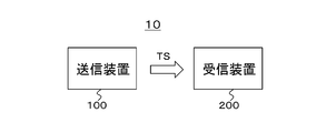
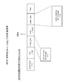
- FIG. 1 shows a configuration example of a transmission / reception system 10 as an embodiment.
- the transmission / reception system 10 includes a transmission device 100 and a reception device 200.
- the transmission apparatus 100 generates an MPEG2 transport stream TS as a container, and transmits the transport stream TS on a broadcast wave or a net packet.
- This transport stream TS has a video stream obtained by encoding transmission video data obtained by applying predetermined photoelectric conversion characteristics to input video data.
- the input video data is HDR (High Dynamic Range) having a contrast ratio of 0% to 100% * N (N is a number greater than 1) exceeding the brightness of the white peak of a conventional LDR (Low Dynamic Range) image.
- N is a number greater than 1
- This is video data of an image.
- a level of 100% is premised on a luminance level corresponding to a white luminance value of 100 cd / m 2.
- the area information indicating the area that allows the luminance conversion is inserted into the layer of the video stream.
- metadata indicating an area where luminance conversion is allowed is inserted into a video stream layer.
- the transmission method 2 is adopted, the above-mentioned predetermined photoelectric conversion characteristic designation information associated with an area allowing luminance conversion is inserted. Details of this area information will be described later.
- the receiving device 200 receives the transport stream TS transmitted from the transmitting device 100 on broadcast waves or net packets.
- the transport stream TS has a video stream including encoded video data.
- area information indicating an area where luminance conversion is allowed is inserted.
- the receiving apparatus 200 applies to the transmission video data, for example, a reverse photoelectric conversion characteristic corresponding to the predetermined photoelectric conversion characteristic on the transmission side described above, and performs luminance conversion processing based on the region information to output video data To get.
- luminance conversion depending on, for example, the peak luminance of the monitor is performed only in the region that allows luminance conversion.
- FIG. 2 shows a configuration example of the transmission device 100.
- the transmission apparatus 100 includes a control unit 101, an HDR camera 102, an HDR photoelectric conversion unit 103, a video encoder 104, a system encoder 105, and a transmission unit 106.
- the control unit 101 includes a CPU (Central Processing Unit), and controls the operation of each unit of the transmission device 100 based on a control program stored in a storage (not shown).
- a CPU Central Processing Unit
- the HDR camera 102 images a subject and outputs HDR (High Dynamic Range) video data.
- This HDR video data has a contrast ratio of 0 to 100% * N (N is a number greater than 1) exceeding the brightness of the white peak of a conventional LDR (Low Dynamic Range) image, for example, 0 to 1000%.
- the level of 100% corresponds to, for example, a white luminance value of 100 cd / m 2.
- “Cd / m2” represents “cd / square meter”.
- the master monitor 103a is a monitor for grading HDR video data obtained by the HDR camera 102.
- the master monitor 103a has a display luminance level corresponding to the HDR video data or suitable for grading the HDR video data.
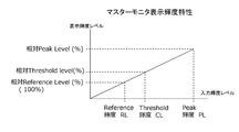
- FIG. 3 shows the display luminance characteristics of the master monitor 103a.
- the horizontal axis indicates the input luminance level
- the vertical axis indicates the display luminance level.
- the display luminance level is a relative reference level (%), for example, 100% corresponding to a white luminance value of 100 cd / m2.
- the display luminance level is a relative peak level (%).
- the threshold luminance CL is newly defined in this embodiment, and indicates the boundary between the region to be matched as the luminance displayed on the monitor (CE monitor) on the receiver side and the region dependent on the CE monitor.
- the monitor input luminance level is the threshold luminance CL
- the display luminance level is a relative threshold level (%).
- the HDR photoelectric conversion unit 103 applies the HDR image photoelectric conversion characteristics (HDR OETF curve) to the HDR video data obtained by the HDR camera 102 to obtain transmission video data V1.
- HDR image photoelectric conversion characteristics HDR OETF curve
- FIG. 4 shows an example of photoelectric conversion characteristics (OETF).
- the horizontal axis indicates the input luminance level
- the vertical axis indicates the transmission code value, similarly to the horizontal axis of the above-described master monitor display luminance characteristic (see FIG. 3).
- the transmission code value is the reference level RP.
- the transmission code value is the peak level MP.
- the transmission code value is the threshold level THP.
- the range of the transmission code value on the vertical axis corresponds to the input pixel data range of the video encoder 104 (Encoder input pixel data range). For example, in the case of 10-bit encoding, the range is “64” to “940”, or “4” to “1019” when the extended area is used.
- the video encoder 104 performs encoding such as MPEG4-AVC, MPEG2 video, or HEVC (high-efficiency-video coding) on the transmission video data V1 to obtain encoded video data. Further, the video encoder 104 generates a video stream (video elementary stream) including the encoded video data by a stream formatter (not shown) provided in the subsequent stage.
- encoding such as MPEG4-AVC, MPEG2 video, or HEVC (high-efficiency-video coding) on the transmission video data V1 to obtain encoded video data. Further, the video encoder 104 generates a video stream (video elementary stream) including the encoded video data by a stream formatter (not shown) provided in the subsequent stage.
- the video encoder 104 inserts area information indicating an area allowing luminance conversion depending on the display side into the layer of the video stream.
- area information indicating an area allowing luminance conversion depending on the display side into the layer of the video stream.
- metadata indicating an area where luminance conversion is allowed is inserted into a video stream layer.
- the transmission method 2 the designation information of the photoelectric conversion characteristics applied in the above-described HDR photoelectric conversion unit 103, which is associated with the area allowing the luminance conversion, is inserted.
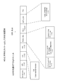
- FIG. 5 shows the top access unit of GOP (Group Of Pictures) when the encoding method is HEVC.
- FIG. 6 shows access units other than the head of the GOP when the encoding method is HEVC.
- a decoding SEI message group “Prefix_SEIs” is arranged before a slice (slices) in which pixel data is encoded, and a display SEI message group “ “Suffix_SEIs” is arranged.
- the level mapping SEI message is arranged as a SEI message group “Suffix_SEIs”.
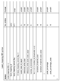
- FIG. 7 shows a structure example (Syntax) of the level mapping SEI message.
- FIG. 8 shows the contents (Semantics) of main information in the structural example.
- “Level_mapping_cancel_flag” is 1-bit flag information. “1” indicates that the message state of the previous level mapping (Level_mapping) is cancelled. “0” indicates that each element is transmitted, so that the previous state is refreshed.
- the 8-bit field of “coded_data_bit_depth” indicates the bit length of the encoded data, and for example, 8 to 14 bits are used.
- a 16-bit field of “reference_white_level” indicates an input luminance value when the master monitor 103a is 100%, that is, a reference luminance RL.
- a 16-bit field of “reference_white_level_code_value” indicates a level code value with a luminance of 100% and a value with bit precision indicated by “coded_data_bit_depth”, that is, a reference level RP.
- the 8-bit field of“ number_of_thresholds ” indicates the number of threshold divisions for display mapping.
- the 16-bit field of “compliant_threshold_level” and the 16-bit field of “compliant_threshold_level_value” exist as many times as the number of threshold divisions. In this embodiment, it is “1”.
- the field of “compliant_threshold_level” indicates a threshold level (percentage) assuming display mapping, and indicates a relative level with respect to 100% luminance, that is, threshold luminance CL.
- the field of “compliant_threshold_level_value” indicates a code value for transmitting a threshold value that assumes display mapping, that is, a threshold level THP. This value is the maximum luminance value that the production side expects to match in the CE monitor display, and a level exceeding this value is an area (range) that can be changed depending on the display capability of the CE monitor. .
- these threshold values are information on a plurality of areas (area division information) with different permissible levels of luminance conversion.
- the 8-bit field of “peak_percentage” indicates a value representing the maximum luminance level as a percentage of 100% on the production side. For example, “peak_percentage” with a peak luminance of 1000 cd / m 2 is 1000%.
- the 16-bit field of “peak_percentage_value” indicates the maximum code value representing “peak_percentage”, that is, the peak level MP when transmitting with the bit precision indicated by “coded_data_bit_depth”. For example, when “peak_percentage” is 1000%, the maximum value “1019” during 10-bit transmission represents 1000%.
- the information of “compliant_threshold_level” and “compliant_threshold_level_value” constitutes area information indicating an area where luminance conversion is allowed.
- the receiving side can detect area information indicating an area allowing luminance conversion from the level, mapping, and SEI message.
- this transmission method 1 an area where luminance conversion is allowed can be designated for each picture, each scene, or each program.
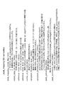
- the transmission method 1 it is assumed that the target OETF (photoelectric conversion characteristic) type is transmitted in the video usability information (VUI) to the NPS unit of SPS (sequence parameter set).
- VUI video usability information
- VUI video usability information
- VUI designates parameters related to display control after decoding, in addition to buffer management timing information, among header information encoded in sequence units as SPS.
- the VUI specifies the screen aspect ratio, color gamut, OETF (photoelectric conversion). (Contains information indicating the control method leading to image display, such as the type of characteristic) and the type of RGB conversion matrix.
- the transfer functions of these two types of OETF are equal and are as follows:
- the receiving side is assumed to convert the above inverse function as EOTF or inverse OETF.
- the OETF applied by the HDR photoelectric conversion unit 103 is any one of OETFs associated with areas that allow luminance conversion in advance.
- the following pieces of information are defined as specifications for each OETF.
- the information of “compliant_threshold_level” and “compliant_threshold_level_value” constitutes area information indicating an area where luminance conversion is allowed.
- the contents of each information are the same as the corresponding information of the above-described level mapping SEI message.
- FIGS. 9A and 9B show an example of an OETF (photoelectric conversion characteristic) in which a region allowing luminance conversion is associated in advance.
- the peak luminance is PL1
- the corresponding transmission code value is MP1.
- a threshold luminance CL1 and a threshold level THP1 are defined as region information indicating a region where luminance conversion is allowed.
- the peak luminance is PL2, and the corresponding transmission code value is MP2.
- a threshold luminance CL2 and a threshold level THP2 are defined as area information indicating areas where luminance conversion is allowed.
- an OETF applied by the HDR photoelectric conversion unit 103 that is, an OETF associated with an area that allows luminance conversion in advance is specified.
- the receiving side can uniquely detect the area information indicating the area where the luminance conversion is allowed from the OETF specified by the VUI.
- EOTF electro-optical conversion characteristics
- OETF photo-electric conversion characteristics
- the display side can be represented by defining region information (information of “compliant_threshold_level” or “compliant_threshold_level_value”) indicating a region where luminance conversion is allowed as OETF specifications.
- the system encoder 105 generates a transport stream TS including the video stream VS generated by the video encoder 104. Then, the transmission unit 106 transmits this transport stream TS to the reception device 200 by placing it on a broadcast wave or a network packet.
- HDR video data obtained by imaging with the HDR camera 102 is supplied to the HDR photoelectric conversion unit 103.
- the HDR video data obtained by the HDR camera 102 is graded using the master monitor 103a.
- HDR video photoelectric conversion characteristics LDR OETF curve
- the transmission video data V1 is supplied to the video encoder 104.
- the transmission video data V1 is encoded by, for example, MPEG4-AVC, MPEG2 video, HEVC, or the like to obtain encoded video data.
- a video stream (video elementary stream) VS including the encoded video data is generated by a stream formatter (not shown) provided in the subsequent stage.
- the video encoder 104 inserts area information indicating an area allowing luminance conversion into the layer of the video stream.
- area information indicating an area allowing luminance conversion into the layer of the video stream.
- metadata indicating an area allowing luminance conversion is inserted into the layer of the video stream.
- the transmission method 2 is adopted, as described above, the designation information of the photoelectric conversion characteristics applied in the above-described HDR photoelectric conversion unit 103, which is associated with the area where the luminance conversion is allowed, is inserted.
- the video stream VS generated by the video encoder 104 is supplied to the system encoder 105.
- This system encoder 105 generates an MPEG2 transport stream TS including a video stream.
- the transport stream TS is transmitted to the receiving apparatus 200 by the transmitting unit 106 on a broadcast wave or a net packet.
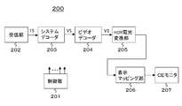
- FIG. 10 shows a configuration example of the receiving device 200.
- the receiving apparatus 200 includes a control unit 201, a receiving unit 202, a system decoder 203, a video decoder 204, an HDR electro-optic conversion unit 205, a display mapping unit 206, and a CE monitor 207.
- the control unit 201 includes a CPU (Central Processing Unit), and controls the operation of each unit of the receiving device 200 based on a control program stored in a storage (not shown).
- CPU Central Processing Unit
- the receiving unit 202 receives the transport stream TS transmitted from the transmitting device 100 on broadcast waves or net packets.
- the system decoder 203 extracts a video stream (elementary stream) VS from the transport stream TS. Further, the system decoder 203 extracts various information inserted in the container (transport stream) layer and sends it to the control unit 201.
- the video decoder 204 performs a decoding process on the video stream VS extracted by the system decoder 203 and outputs transmission video data V1. In addition, the video decoder 204 extracts a parameter set or SEI message inserted in each access unit constituting the video stream VS and sends it to the control unit 201.
- the control unit 201 recognizes the OETF (photoelectric conversion characteristics) applied on the transmission side by specifying the OETF type in the video usability information (VUI) of the SPS, and the HDR electro-optic conversion unit 205 corresponds to the OETF.
- OETF photoelectric conversion characteristics
- VUI video usability information
- EOTF electro-optic conversion characteristic having reverse characteristics
- control unit 201 obtains region information (“compliant_threshold_level” and “compliant_threshold_level_value” information) indicating a region where luminance conversion is permitted from the OETF specified by the VUI. It can be detected uniquely.
- the level mapping SEI message described above is included as one of the SEI messages extracted by the video decoder 204 and sent to the control unit 201.
- the control unit 201 can acquire area information (information of “compliant_threshold_level” and “compliant_threshold_level_value”) indicating an area for which luminance conversion is allowed from the level mapping SEI message.
- the HDR electro-optical conversion unit 205 corresponds to the transmission video data V1 output from the video decoder 204, for example, an EOTF (electro-optical conversion) corresponding to the OETF (photo-electric conversion characteristic) in the HDR photoelectric conversion unit 103 of the transmission device 100 described above. To obtain output video data for displaying HDR images.
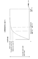
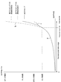
- FIG. 11 shows an example of electro-optic conversion characteristics (EOTF).
- the horizontal axis indicates a transmission code value corresponding to the vertical axis in FIG.
- the vertical axis represents the output luminance level (display luminance level) corresponding to the horizontal axis in FIG.
- a solid line a is an EOTF curve.
- the transmission code value is the peak level MP
- the output luminance level is PL.
- the transmission code value is the threshold level THP
- the output luminance level is CL.
- the output luminance level corresponding to the value of the transmission code value larger than the threshold level THP is the display mapping unit.
- the range is allocated to the range up to the maximum display luminance level DP1 of the CE monitor 207 (high luminance processing).
- an alternate long and two short dashes line b shows an example of luminance conversion processing in that case.
- the output luminance level corresponding to a value whose transmission code value is larger than the threshold level THP is the display mapping unit 206. Is assigned to the range up to the display maximum brightness level DP2 of the CE monitor 207 (low brightness processing).
- an alternate long and short dash line c indicates an example of luminance conversion processing in that case.
- the display mapping unit 206 converts the level exceeding the luminance CL among the output luminance levels of the HDR electro-optic conversion unit 205 according to the maximum luminance display capability of the CE monitor 207 as described above.
- the transmission code value is equal to or less than the threshold level THP, that is, the output luminance level is equal to or less than CL
- the luminance of the reception level is faithfully reproduced without depending on the CE monitor 207. Intent is expressed correctly.
- the CE monitor 207 displays an HDR image based on the output video data from the display mapping unit 206.
- the display mapping processing unit 206 sets the level exceeding the luminance CL to the peak luminance DP.
- the brightness enhancement process assigned by a predetermined algorithm is performed within the above range.
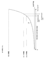
- FIG. 12 shows the display luminance characteristics of the CE monitor 207 in that case.
- This characteristic includes the luminance conversion characteristic of the display mapping unit 206.
- the horizontal axis indicates the input luminance level
- the vertical axis indicates the display luminance level.
- the input luminance level is the threshold luminance CL
- the relative threshold level (%) is obtained.
- the display luminance level is the relative peak level (%) of the CE monitor 207.
- the display mapping processing unit 206 When the maximum luminance display capability DP of the CE monitor 207 is lower than the maximum luminance PL assumed by the master monitor 103a, that is, when DP ⁇ PL, the display mapping processing unit 206 peaks the level exceeding the luminance CL. Luminance reduction processing assigned by a predetermined algorithm is performed in a range up to the luminance DP.
- FIG. 13 shows the display luminance characteristics of the CE monitor 207 in that case.
- This characteristic includes the luminance conversion characteristic of the display mapping unit 206.
- the horizontal axis indicates the input luminance level
- the vertical axis indicates the display luminance level.
- the input luminance level is the threshold luminance CL
- the relative threshold level (%) is obtained.
- the display luminance level is the relative peak level (%) of the CE monitor 207.
- the display mapping processing unit 206 performs luminance conversion at a level exceeding the luminance CL. Output as is without processing. In this case, the display on the CE monitor 207 is displayed with the production-side luminance assigned as it is in the entire area up to the peak level of the master monitor 103a.
- the reception unit 202 receives the transport stream TS transmitted from the transmission device 100 on broadcast waves or net packets.
- This transport stream TS is supplied to the system decoder 203.
- the system decoder 203 extracts a video stream (elementary stream) VS from the transport stream TS.
- the video stream VS extracted by the system decoder 203 is supplied to the video decoder 204.
- the video decoder 204 performs a decoding process on the video stream VS extracted by the system decoder 203 to obtain transmission video data V1. Further, the video decoder 204 extracts a parameter set and SEI message inserted in each access unit constituting the video stream VS and sends the extracted parameter set and SEI message to the control unit 201.
- the control unit 201 acquires area information (information of “compliant_threshold_level” and “compliant_threshold_level_value”) indicating an area that allows luminance conversion from the level mapping SEI message.
- area information information of “compliant_threshold_level” and “compliant_threshold_level_value”
- the control unit 201 uniquely identifies region information (“compliant_threshold_level” and “compliant_threshold_level_value” information) indicating a region where luminance conversion is allowed from the OETF specified by the VUI. Detected.
- Transmission video data V1 obtained by the video decoder 204 is supplied to the HDR electro-optic conversion unit 205.
- an EOTF electro-optic conversion characteristic
- OETF photo-electric conversion characteristic
- Transmission video data V1 obtained by the video decoder 204 is supplied to the HDR electro-optic conversion unit 205.
- an EOTF electro-optic conversion characteristic having a reverse characteristic corresponding to the OETF (photo-electric conversion characteristic) in the HDR photoelectric conversion unit 103 in the transmission device 100
- the output video data for displaying is obtained. This output video data is supplied to the display mapping unit 206.
- the level exceeding the luminance CL among the output luminance levels of the HDR electro-optic conversion unit 205 is converted according to the maximum luminance display capability of the CE monitor 207.
- the output video data of the display mapping unit 206 is supplied to the CE monitor 207.
- An HDR image is displayed on the CE monitor 207.
- the transmission video data V1 obtained by photoelectrically converting the HDR video data includes region information (“compliant_threshold_level” or “compliant_threshold_level_value” indicating a region where luminance conversion is allowed. ”)"). Therefore, on the receiving side, for example, the luminance conversion corresponding to the display luminance capability of the CE monitor 207 is performed only in the area where the luminance conversion is allowed, so that the luminance atmosphere intended by the production side can be reproduced well.
- FIG. 14 shows an example of the relationship between the electro-optic conversion characteristics (EOTF) in the HDR electro-optic converter 205 of the receiving apparatus 200 and a plurality of sets of threshold information. This example shows a case where two pieces of threshold information are sent.
- a solid line a is an EOTF curve.
- the transmission code value is the peak level MP
- the output luminance level is PL.
- the transmission code values are threshold levels THP0 and THP1
- the output luminance levels are CL0 and CL1, respectively.
- the two sets of threshold information (CL0, THP0) and (CL1, THP1) are given by the level mapping SEI message.
- the region where the transmission code value is 0 to THP0 is a region where luminance conversion is not permitted, and is a region where the display luminance level is the same on any type of CE monitor. Therefore, regarding the output luminance level of this area, the display mapping unit 206 does not perform luminance conversion processing.
- the area where the transmission code value is THP 0 to MP is an area where luminance conversion is allowed. Therefore, regarding the output luminance level of this region, the display mapping unit 206 performs luminance conversion processing according to the maximum display capability of the CE monitor 207, for example.
- the THP 0 to THP 1 area and the THP 1 to MP area have different luminance conversion allowable levels. For example, in the THP0 to THP1 areas, luminance conversion can be performed within a range where the texture is stored. In addition, the luminance conversion is possible for the THP1 to MP regions without any limitation.
- a plurality of threshold information can be inserted and transmitted in the level mapping SEI message.
- one threshold information that is basic as the specification of the OETF (photoelectric conversion characteristics) specified by the VUI is sent, and for the other threshold information, for example, a level mapping SEI message is used. And send it.
- the threshold luminance CL is defined and used in addition to the reference luminance RL.
- the reference luminance RL is synonymous with the threshold luminance CL.
- information on the reference luminance RL and the reference level RP is also sent as threshold information.
- the reference luminance RL and the reference level RP are not necessarily limited to the luminance of 100%, and it is possible to define another percentage value as a level that matches on the transmission / reception side.
- FIG. 15 shows a structure example (Syntax) of a level mapping SEI message that is inserted into the “SEIs” portion of the access unit (AU) and transmitted when the transmission method 1 is adopted.
- the contents (Semantics) of the main information in this structural example are the same as the level mapping SEI message shown in FIG.
- the 16-bit field of “reference_white_level” indicates an input luminance value at 100% in the master monitor 103a, that is, a reference luminance RL, and also indicates a luminance value at a threshold level assuming display mapping.
- FIGS. 16A and 16B show an example of OETF (photoelectric conversion characteristics) in which a region that allows luminance conversion is associated in advance when the transmission method 2 is employed.
- the peak luminance is PL1
- the corresponding transmission code value is MP1.
- a reference luminance RL1 and a reference level RP1 are defined as region information indicating a region where luminance conversion is allowed.
- the peak luminance is PL2, and the corresponding transmission code value is MP2.
- a reference luminance RL2 and a reference level RP2 are defined as region information indicating a region where luminance conversion is allowed.
- the HDR light-to-light conversion unit 205 performs light-light conversion processing
- the display mapping unit 206 performs luminance conversion processing according to the maximum luminance display capability of the CE monitor 207. Indicated.
- the electro-optical conversion process and the luminance conversion process can be performed simultaneously only by the HDR electro-optical conversion unit 205.
- the transmission / reception system 10 including the transmission device 100 and the receiver 200 is shown, but the configuration of the transmission / reception system to which the present technology can be applied is not limited thereto.
- the television receiver 200 has a configuration including a set top box 200A and a monitor 200B connected by a digital interface such as (High-Definition Multimedia Interface (HDMI)).
- HDMI High-Definition Multimedia Interface
- the set top box 200A can determine the maximum luminance level of the monitor 200B based on information obtained from the EDID of the monitor 200B via HDMI.
- the level / mapping / SEI message, the EOTF type, and the VUI information are defined in meta information such as “Vender Specific Info ⁇ Frame”. It can be shared with the monitor 200B.
- the container is a transport stream (MPEG-2 TS)
- MPEG-2 TS transport stream
- the transport is not limited to the TS, and the video layer can be realized by the same method even in the case of other packets such as ISOBMFF and MMT. Therefore, the present technology can be similarly applied to a system configured to be distributed to receiving terminals using a network such as the Internet.
- the Internet distribution it is often distributed in a container of MP4 or other formats.
- containers of various formats such as transport stream (MPEG-2 TS) adopted in the digital broadcasting standard and MP4 used in Internet distribution correspond to the container.
- this technique can also take the following structures.
- a processing unit that obtains transmission video data by applying predetermined photoelectric conversion characteristics to input video data;
- a transmission device comprising: a transmission unit configured to transmit the transmission video data together with area information indicating an area allowing luminance conversion.
- the transmission unit transmits a video stream obtained by encoding the transmission video data, The transmission device according to (1), further including an information insertion unit that inserts the region information into a layer of the video stream.
- the information insertion unit The transmission apparatus according to (2), wherein metadata indicating a region that permits the luminance conversion is inserted as the region information.
- the information insertion unit The transmission apparatus according to (2), wherein the specified information of the predetermined photoelectric conversion characteristic associated with the area allowing the luminance conversion is inserted as the area information.
- a receiving unit that receives transmission video data obtained by applying predetermined photoelectric conversion characteristics to input video data together with area information indicating an area allowing luminance conversion; And a processing unit that applies electro-optic conversion characteristics corresponding to the predetermined photoelectric conversion characteristics to the transmission video data, and performs luminance conversion processing based on the region information to obtain output video data.
- the reception unit receives a video stream obtained by encoding the transmission video data, The receiving apparatus according to (7), wherein the region information is inserted in a layer of the video stream.
- the receiving device according to (8), wherein metadata indicating a region allowing the luminance conversion is inserted as the region information.
- the receiving device (10) The receiving device according to (8), wherein the predetermined information of the predetermined photoelectric conversion characteristic associated with the area allowing the luminance conversion is inserted as the area information.
- the reception apparatus according to any one of (7) to (10), wherein the area information includes information on a plurality of areas having different luminance conversion allowable levels.
- a receiving step of receiving transmission video data obtained by applying predetermined photoelectric conversion characteristics to input video data together with area information indicating an area allowing luminance conversion;
- a receiving method comprising: applying an electro-optic conversion characteristic corresponding to the predetermined photoelectric conversion characteristic to the transmission video data, and performing luminance conversion processing based on the region information to obtain output video data.
- the main feature of this technology is that transmission video data obtained by performing photoelectric conversion on HDR video data is transmitted together with area information indicating an area where luminance conversion is allowed, thereby allowing luminance conversion on the receiving side.
- the luminance conversion is performed only in the area to be reproduced, and the luminance atmosphere intended by the production side can be reproduced well (see FIGS. 4 and 7).
Abstract
Description
入力ビデオデータに所定の光電変換特性を適用して伝送ビデオデータを得る処理部と、
上記伝送ビデオデータを、輝度変換を許容する領域を示す領域情報と共に送信する送信部とを備える
送信装置にある。
入力ビデオデータに所定の光電変換特性を適用して得られた伝送ビデオデータを、輝度変換を許容する領域を示す領域情報と共に受信する受信部と、
上記伝送ビデオデータに上記所定の光電変換特性に対応する電光変換特性を適用すると共に、上記領域情報に基づいて輝度変換処理を施して出力ビデオデータを得る処理部とを備える
受信装置にある。
1.実施の形態
2.変形例
[送受信システムの構成例]
図1は、実施の形態としての送受信システム10の構成例を示している。この送受信システム10は、送信装置100および受信装置200により構成されている。
図2は、送信装置100の構成例を示している。この送信装置100は、制御部101と、HDRカメラ102と、HDR光電変換部103と、ビデオエンコーダ104と、システムエンコーダ105と、送信部106を有している。制御部101は、CPU(Central Processing Unit)を備えて構成され、図示しないストレージに格納されている制御プログラムに基づいて、送信装置100の各部の動作を制御する。
輝度変換を許容する領域を示す領域情報の挿入の詳細を説明する。
「伝送方法1を採用する場合」
最初に伝送方法1を採用する場合について説明する。アクセスユニット(AU)の“SEIs”の部分に、新規定義する、レベル・マッピング・SEIメッセージ(Level_mapping SEI message)を挿入する。
次に、伝送方法2を採用する場合について説明する。図5に示すように、GOPの先頭のアクセスユニットのSPS(sequence parameter set)のNALユニットに、ビデオ・ユーザビリティ情報(VUI)が挿入されている。
V = 4.500 * Lc for 0.018 > Lc >= 0
受信側は、上記の逆関数をEOTF、あるいは逆OETFとして変換することが前提となる。
「reference_white_level」
「reference_white_level_code_value」
「compliant_threshold_level」
「compliant_threshold_level_value」
「peak_percentage」
「peak_percentage_value」
図10は、受信装置200の構成例を示している。この受信装置200は、制御部201と、受信部202と、システムデコーダ203と、ビデオデコーダ204と、HDR電光変換部205と、表示マッピング部206と、CEモニタ207を有している。制御部201は、CPU(Central Processing Unit)を備えて構成され、図示しないストレージに格納されている制御プログラムに基づいて、受信装置200の各部の動作を制御する。
なお、上述実施の形態において、伝送方法1が採用される場合は、アクセスユニット(AU)の“SEIs”の部分に、新規定義する、レベル・マッピング・SEIメッセージ(図7参照)が挿入される。上述実施の形態では、このレベル・マッピング・SEIメッセージで、「compliant_threshold_level」および「compliant_threshold_level_value」の情報(閾値情報)を一つだけ送る例を示したが、この閾値情報を複数送ることも考えられる。
(1)入力ビデオデータに所定の光電変換特性を適用して伝送ビデオデータを得る処理部と、
上記伝送ビデオデータを、輝度変換を許容する領域を示す領域情報と共に送信する送信部とを備える
送信装置。
(2)上記送信部は、上記伝送ビデオデータが符号化されて得られたビデオストリームを送信し、
上記ビデオストリームのレイヤに、上記領域情報を挿入する情報挿入部をさらに備える
前記(1)に記載の送信装置。
(3)上記情報挿入部は、
上記領域情報として、上記輝度変換を許容する領域を示すメタデータを挿入する
前記(2)に記載の送信装置。
(4)上記情報挿入部は、
上記領域情報として、上記輝度変換を許容する領域が関連づけられた上記所定の光電変換特性の指定情報を挿入する
前記(2)に記載の送信装置。
(5)上記領域情報は、輝度変換の許容レベルを異にする複数の領域の情報を含む
前記(1)から(4)のいずれかに記載の送信装置。
(6)入力ビデオデータに所定の光電変換特性を適用して伝送ビデオデータを得る処理ステップと、
送信部により、上記伝送ビデオデータを、輝度変換を許容する領域を示す領域情報と共に送信する送信ステップとを有する
送信方法。
(7)入力ビデオデータに所定の光電変換特性を適用して得られた伝送ビデオデータを、輝度変換を許容する領域を示す領域情報と共に受信する受信部と、
上記伝送ビデオデータに上記所定の光電変換特性に対応する電光変換特性を適用すると共に、上記領域情報に基づいて輝度変換処理を施して出力ビデオデータを得る処理部とを備える
受信装置。
(8)上記受信部は、上記伝送ビデオデータが符号化されて得られるビデオストリームを受信し、
上記領域情報は、上記ビデオストリームのレイヤに挿入されている
前記(7)に記載の受信装置。
(9)上記領域情報として、上記輝度変換を許容する領域を示すメタデータが挿入されている
前記(8)に記載の受信装置。
(10)上記領域情報として、上記輝度変換を許容する領域が関連づけられた上記所定の光電変換特性の指定情報が挿入されている
前記(8)に記載の受信装置。
(11)上記領域情報は、輝度変換の許容レベルを異にする複数の領域の情報を含む
前記(7)から(10)のいずれかに記載の受信装置。
(12)受信部により、入力ビデオデータに所定の光電変換特性を適用して得られた伝送ビデオデータを、輝度変換を許容する領域を示す領域情報と共に受信する受信ステップと、
上記伝送ビデオデータに上記所定の光電変換特性に対応する電光変換特性を適用すると共に、上記領域情報に基づいて輝度変換処理を施して出力ビデオデータを得る処理ステップとを有する
受信方法。
100・・・送信装置
101・・・制御部
102・・・HDRカメラ
103・・・HDR光電変換部
103a・・・マスターモニタ
104・・・ビデオエンコーダ
105・・・システムエンコーダ
106・・・送信部
200・・・受信装置
200A・・・セットアップボックス
200B・・・モニタ
201・・・制御部
202・・・受信部
203・・・システムデコーダ
204・・・ビデオデコーダ
205・・・HDR電光変換部
206・・・表示マッピング部
207・・・CEモニタ
Claims (12)
- 入力ビデオデータに所定の光電変換特性を適用して伝送ビデオデータを得る処理部と、
上記伝送ビデオデータを、輝度変換を許容する領域を示す領域情報と共に送信する送信部とを備える
送信装置。 - 上記送信部は、上記伝送ビデオデータが符号化されて得られたビデオストリームを送信し、
上記ビデオストリームのレイヤに、上記領域情報を挿入する情報挿入部をさらに備える
請求項1に記載の送信装置。 - 上記情報挿入部は、
上記領域情報として、上記輝度変換を許容する領域を示すメタデータを挿入する
請求項2に記載の送信装置。 - 上記情報挿入部は、
上記領域情報として、上記輝度変換を許容する領域が関連づけられた上記所定の光電変換特性の指定情報を挿入する
請求項2に記載の送信装置。 - 上記領域情報は、輝度変換の許容レベルを異にする複数の領域の情報を含む
請求項1に記載の送信装置。 - 入力ビデオデータに所定の光電変換特性を適用して伝送ビデオデータを得る処理ステップと、
送信部により、上記伝送ビデオデータを、輝度変換を許容する領域を示す領域情報と共に送信する送信ステップとを有する
送信方法。 - 入力ビデオデータに所定の光電変換特性を適用して得られた伝送ビデオデータを、輝度変換を許容する領域を示す領域情報と共に受信する受信部と、
上記伝送ビデオデータに上記所定の光電変換特性に対応する電光変換特性を適用すると共に、上記領域情報に基づいて輝度変換処理を施して出力ビデオデータを得る処理部とを備える
受信装置。 - 上記受信部は、上記伝送ビデオデータが符号化されて得られるビデオストリームを受信し、
上記領域情報は、上記ビデオストリームのレイヤに挿入されている
請求項7に記載の受信装置。 - 上記領域情報として、上記輝度変換を許容する領域を示すメタデータが挿入されている
請求項8に記載の受信装置。 - 上記領域情報として、上記輝度変換を許容する領域が関連づけられた上記所定の光電変換特性の指定情報が挿入されている
請求項8に記載の受信装置。 - 上記領域情報は、輝度変換の許容レベルを異にする複数の領域の情報を含む
請求項7に記載の受信装置。 - 受信部により、入力ビデオデータに所定の光電変換特性を適用して得られた伝送ビデオデータを、輝度変換を許容する領域を示す領域情報と共に受信する受信ステップと、
上記伝送ビデオデータに上記所定の光電変換特性に対応する電光変換特性を適用すると共に、上記領域情報に基づいて輝度変換処理を施して出力ビデオデータを得る処理ステップとを有する
受信方法。
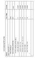
Priority Applications (5)
| Application Number | Priority Date | Filing Date | Title |
|---|---|---|---|
| RU2016147783A RU2696216C2 (ru) | 2014-06-13 | 2015-05-19 | Передающее устройство, способ передачи, приемное устройство и способ приема |
| CN201580030229.2A CN106416261B (zh) | 2014-06-13 | 2015-05-19 | 传输设备、传输方法、接收设备以及接收方法 |
| EP15806088.9A EP3157257A4 (en) | 2014-06-13 | 2015-05-19 | Transmission device, transmission method, reception device, and reception method |
| US15/308,155 US11418753B2 (en) | 2014-06-13 | 2015-05-19 | Transmission device, transmission method, reception device, and reception method |
| JP2016527715A JP6531759B2 (ja) | 2014-06-13 | 2015-05-19 | 送信装置、送信方法、受信装置および受信方法 |
Applications Claiming Priority (2)
| Application Number | Priority Date | Filing Date | Title |
|---|---|---|---|
| JP2014-122910 | 2014-06-13 | ||
| JP2014122910 | 2014-06-13 |
Publications (1)
| Publication Number | Publication Date |
|---|---|
| WO2015190246A1 true WO2015190246A1 (ja) | 2015-12-17 |
Family
ID=54833351
Family Applications (1)
| Application Number | Title | Priority Date | Filing Date |
|---|---|---|---|
| PCT/JP2015/064384 WO2015190246A1 (ja) | 2014-06-13 | 2015-05-19 | 送信装置、送信方法、受信装置および受信方法 |
Country Status (6)
| Country | Link |
|---|---|
| US (1) | US11418753B2 (ja) |
| EP (1) | EP3157257A4 (ja) |
| JP (2) | JP6531759B2 (ja) |
| CN (1) | CN106416261B (ja) |
| RU (1) | RU2696216C2 (ja) |
| WO (1) | WO2015190246A1 (ja) |
Cited By (10)
| Publication number | Priority date | Publication date | Assignee | Title |
|---|---|---|---|---|
| WO2016088344A1 (ja) * | 2014-12-03 | 2016-06-09 | パナソニックIpマネジメント株式会社 | データ生成方法、データ再生方法、データ生成装置及びデータ再生装置 |
| JP2016111692A (ja) * | 2014-12-03 | 2016-06-20 | パナソニックIpマネジメント株式会社 | データ生成方法、データ再生方法、データ生成装置及びデータ再生装置 |
| JP2017121010A (ja) * | 2015-12-28 | 2017-07-06 | ソニー株式会社 | 送信装置、送信方法、受信装置および受信方法 |
| JP2017163536A (ja) * | 2016-03-02 | 2017-09-14 | シャープ株式会社 | 受信装置および放送システム |
| CN107395950A (zh) * | 2016-05-16 | 2017-11-24 | 西安电子科技大学 | 媒体数据处理方法和装置及系统 |
| WO2018062022A1 (ja) * | 2016-09-28 | 2018-04-05 | パナソニックIpマネジメント株式会社 | 調整装置、調整方法およびプログラム |
| JP2018093320A (ja) * | 2016-12-01 | 2018-06-14 | 日本放送協会 | 映像信号変換装置およびそのプログラム、ならびに、映像表示装置 |
| JPWO2018062022A1 (ja) * | 2016-09-28 | 2019-08-29 | パナソニックIpマネジメント株式会社 | 調整装置、調整方法およびプログラム |
| JP2020025333A (ja) * | 2015-09-25 | 2020-02-13 | マクセル株式会社 | 表示装置 |
| JP7367806B2 (ja) | 2020-05-22 | 2023-10-24 | ソニーグループ株式会社 | 送信装置、送信方法、受信装置および受信方法 |
Families Citing this family (2)
| Publication number | Priority date | Publication date | Assignee | Title |
|---|---|---|---|---|
| CN110489073B (zh) * | 2014-06-10 | 2023-09-01 | 松下知识产权经营株式会社 | 变换方法及变换装置 |
| US11244635B2 (en) | 2017-10-12 | 2022-02-08 | Saturn Licensing Llc | Image processing apparatus, image processing method, transmission apparatus, transmission method, and reception apparatus |
Citations (3)
| Publication number | Priority date | Publication date | Assignee | Title |
|---|---|---|---|---|
| WO2013046095A1 (en) * | 2011-09-27 | 2013-04-04 | Koninklijke Philips Electronics N.V. | Apparatus and method for dynamic range transforming of images |
| WO2014002901A1 (ja) * | 2012-06-29 | 2014-01-03 | ソニー株式会社 | 画像処理装置および方法 |
| WO2014178286A1 (ja) * | 2013-04-30 | 2014-11-06 | ソニー株式会社 | 送信装置、送信方法、受信装置および受信方法 |
Family Cites Families (16)
| Publication number | Priority date | Publication date | Assignee | Title |
|---|---|---|---|---|
| JP4372747B2 (ja) * | 2005-01-25 | 2009-11-25 | シャープ株式会社 | 輝度レベル変換装置、輝度レベル変換方法、固体撮像装置、輝度レベル変換プログラム、および記録媒体 |
| KR101511130B1 (ko) * | 2008-07-25 | 2015-04-13 | 삼성디스플레이 주식회사 | 표시영상의 부스팅 방법, 이를 수행하기 위한 콘트롤러유닛 및 이를 갖는 표시장치 |
| JP2011040998A (ja) * | 2009-08-11 | 2011-02-24 | Mitsubishi Electric Corp | 画像表示装置 |
| EP2504829A4 (en) * | 2009-11-27 | 2012-10-31 | Canon Kk | IMAGE DISPLAY DEVICE |
| JP5577415B2 (ja) * | 2010-02-22 | 2014-08-20 | ドルビー ラボラトリーズ ライセンシング コーポレイション | ビットストリームに埋め込まれたメタデータを用いたレンダリング制御を備えるビデオ表示 |
| JP2012014628A (ja) * | 2010-07-05 | 2012-01-19 | Mitsubishi Electric Corp | 画像表示装置 |
| US8624960B2 (en) * | 2010-07-30 | 2014-01-07 | Silicon Image, Inc. | Multi-view display system |
| TWI479898B (zh) * | 2010-08-25 | 2015-04-01 | Dolby Lab Licensing Corp | 擴展影像動態範圍 |
| JP5761946B2 (ja) * | 2010-09-02 | 2015-08-12 | キヤノン株式会社 | 画像処理装置、画像処理方法及び記憶媒体 |
| JP2012199897A (ja) * | 2011-03-04 | 2012-10-18 | Sony Corp | 画像データ送信装置、画像データ送信方法、画像データ受信装置および画像データ受信方法 |
| CN103891294B (zh) * | 2011-04-28 | 2017-09-01 | 皇家飞利浦有限公司 | 用于hdr图像编码和解码的装置与方法 |
| JP6234920B2 (ja) * | 2011-05-10 | 2017-11-22 | コーニンクレッカ フィリップス エヌ ヴェKoninklijke Philips N.V. | ハイダイナミックレンジ画像信号生成及び処理 |
| CN102497490B (zh) * | 2011-12-16 | 2014-08-13 | 上海富瀚微电子有限公司 | 实现图像高动态范围压缩的系统及其方法 |
| KR101998892B1 (ko) * | 2012-03-01 | 2019-07-10 | 소니 주식회사 | 송신 장치, 송신 방법 및 수신 장치 |
| US10110890B2 (en) | 2012-07-02 | 2018-10-23 | Sony Corporation | Video coding system with low delay and method of operation thereof |
| EP2819414A3 (en) * | 2013-06-28 | 2015-02-25 | Samsung Electronics Co., Ltd | Image processing device and image processing method |
-
2015
- 2015-05-19 CN CN201580030229.2A patent/CN106416261B/zh active Active
- 2015-05-19 US US15/308,155 patent/US11418753B2/en active Active
- 2015-05-19 RU RU2016147783A patent/RU2696216C2/ru active
- 2015-05-19 JP JP2016527715A patent/JP6531759B2/ja active Active
- 2015-05-19 EP EP15806088.9A patent/EP3157257A4/en not_active Ceased
- 2015-05-19 WO PCT/JP2015/064384 patent/WO2015190246A1/ja active Application Filing
-
2019
- 2019-05-22 JP JP2019095631A patent/JP6849011B2/ja active Active
Patent Citations (3)
| Publication number | Priority date | Publication date | Assignee | Title |
|---|---|---|---|---|
| WO2013046095A1 (en) * | 2011-09-27 | 2013-04-04 | Koninklijke Philips Electronics N.V. | Apparatus and method for dynamic range transforming of images |
| WO2014002901A1 (ja) * | 2012-06-29 | 2014-01-03 | ソニー株式会社 | 画像処理装置および方法 |
| WO2014178286A1 (ja) * | 2013-04-30 | 2014-11-06 | ソニー株式会社 | 送信装置、送信方法、受信装置および受信方法 |
Non-Patent Citations (4)
| Title |
|---|
| SALLY HATTORI ET AL.: "HLS: SEI message for Knee Function Information", JOINT COLLABORATIVE TEAM ON VIDEO CODING (JCT-VC) OF ITU-T SG 16 WP 3 AND ISO/IEC JTC 1/SC 29/WG 11, JCTVC-P0050-V2, 16TH MEETING, January 2014 (2014-01-01), San Jose, US, pages 1 - 21, XP030115514 * |
| SALLY HATTORI ET AL.: "HLS: SEI message for transfer function information", JOINT COLLABORATIVE TEAM ON VIDEO CODING (JCT- VC) OF ITU-T SG 16 WP 3 AND ISO/IEC JTC 1/SC 29/WG 11, JCTVC-00064, 15TH MEETING, October 2013 (2013-10-01), Geneva, CH, pages 1 - 4, XP030115040 * |
| SALLY HATTORI ET AL.: "Signalling of Luminance Dynamic Range in Tone mapping information SEI", JOINT COLLABORATIVE TEAM ON VIDEO CODING (JCT-VC) OF ITU-T SG 16 WP 3 AND ISO/IEC JTC 1/SC 29/WG 11, JCTVC-J0149, 10TH MEETING, July 2012 (2012-07-01), Stockholm, SE, pages 1 - 7, XP030112511 * |
| See also references of EP3157257A4 * |
Cited By (27)
| Publication number | Priority date | Publication date | Assignee | Title |
|---|---|---|---|---|
| JP2021036714A (ja) * | 2014-12-03 | 2021-03-04 | パナソニックIpマネジメント株式会社 | データ生成方法及び復号装置 |
| JP2020025277A (ja) * | 2014-12-03 | 2020-02-13 | パナソニックIpマネジメント株式会社 | データ符号化方法、データ復号方法、データ符号化装置及びデータ復号装置 |
| JP2020096393A (ja) * | 2014-12-03 | 2020-06-18 | パナソニックIpマネジメント株式会社 | データ生成装置 |
| JP2020096392A (ja) * | 2014-12-03 | 2020-06-18 | パナソニックIpマネジメント株式会社 | データ生成装置 |
| JP2021036713A (ja) * | 2014-12-03 | 2021-03-04 | パナソニックIpマネジメント株式会社 | データ生成方法及び復号装置 |
| WO2016088344A1 (ja) * | 2014-12-03 | 2016-06-09 | パナソニックIpマネジメント株式会社 | データ生成方法、データ再生方法、データ生成装置及びデータ再生装置 |
| JP2020102884A (ja) * | 2014-12-03 | 2020-07-02 | パナソニックIpマネジメント株式会社 | データ生成装置 |
| JP2016111692A (ja) * | 2014-12-03 | 2016-06-20 | パナソニックIpマネジメント株式会社 | データ生成方法、データ再生方法、データ生成装置及びデータ再生装置 |
| JP2021036716A (ja) * | 2014-12-03 | 2021-03-04 | パナソニックIpマネジメント株式会社 | データ生成方法及び復号装置 |
| JP2021036715A (ja) * | 2014-12-03 | 2021-03-04 | パナソニックIpマネジメント株式会社 | データ生成方法及び復号装置 |
| JP2020127208A (ja) * | 2014-12-03 | 2020-08-20 | パナソニックIpマネジメント株式会社 | データ生成装置 |
| JP2020025333A (ja) * | 2015-09-25 | 2020-02-13 | マクセル株式会社 | 表示装置 |
| JP2021121126A (ja) * | 2015-09-25 | 2021-08-19 | マクセル株式会社 | 映像表示装置および映像出力装置 |
| JP7196227B2 (ja) | 2015-09-25 | 2022-12-26 | マクセル株式会社 | 映像表示装置および映像出力装置 |
| CN108293141A (zh) * | 2015-12-28 | 2018-07-17 | 索尼公司 | 用于高动态范围视频数据的发送装置、发送方法、接收装置以及接收方法 |
| CN108293141B (zh) * | 2015-12-28 | 2021-05-25 | 索尼公司 | 用于高动态范围视频数据的发送装置、发送方法、接收装置以及接收方法 |
| US10887670B2 (en) | 2015-12-28 | 2021-01-05 | Sony Corporation | Transmission apparatus, transmission method, reception apparatus, and reception method |
| JP2017121010A (ja) * | 2015-12-28 | 2017-07-06 | ソニー株式会社 | 送信装置、送信方法、受信装置および受信方法 |
| US20190253771A1 (en) | 2015-12-28 | 2019-08-15 | Sony Corporation | Transmission apparatus, transmission method, reception apparatus, and reception method |
| US11368767B2 (en) | 2015-12-28 | 2022-06-21 | Sony Corporation | Transmission apparatus, transmission method, reception apparatus, and reception method |
| JP2017163536A (ja) * | 2016-03-02 | 2017-09-14 | シャープ株式会社 | 受信装置および放送システム |
| US11165944B2 (en) | 2016-05-16 | 2021-11-02 | Xi'an Zhongxing New Software Co., Ltd. | Media data processing method, apparatus and system |
| CN107395950A (zh) * | 2016-05-16 | 2017-11-24 | 西安电子科技大学 | 媒体数据处理方法和装置及系统 |
| JPWO2018062022A1 (ja) * | 2016-09-28 | 2019-08-29 | パナソニックIpマネジメント株式会社 | 調整装置、調整方法およびプログラム |
| WO2018062022A1 (ja) * | 2016-09-28 | 2018-04-05 | パナソニックIpマネジメント株式会社 | 調整装置、調整方法およびプログラム |
| JP2018093320A (ja) * | 2016-12-01 | 2018-06-14 | 日本放送協会 | 映像信号変換装置およびそのプログラム、ならびに、映像表示装置 |
| JP7367806B2 (ja) | 2020-05-22 | 2023-10-24 | ソニーグループ株式会社 | 送信装置、送信方法、受信装置および受信方法 |
Also Published As
| Publication number | Publication date |
|---|---|
| US11418753B2 (en) | 2022-08-16 |
| CN106416261A (zh) | 2017-02-15 |
| CN106416261B (zh) | 2020-06-26 |
| RU2696216C2 (ru) | 2019-07-31 |
| EP3157257A1 (en) | 2017-04-19 |
| EP3157257A4 (en) | 2018-01-17 |
| JP2019193269A (ja) | 2019-10-31 |
| RU2016147783A (ru) | 2018-06-06 |
| JPWO2015190246A1 (ja) | 2017-04-20 |
| RU2016147783A3 (ja) | 2018-12-19 |
| US20170064242A1 (en) | 2017-03-02 |
| JP6531759B2 (ja) | 2019-06-19 |
| JP6849011B2 (ja) | 2021-03-24 |
Similar Documents
| Publication | Publication Date | Title |
|---|---|---|
| JP6849011B2 (ja) | 送信装置、送信方法、受信装置および受信方法 | |
| US11418820B2 (en) | Transmission device, transmission method, reception device, reception method, display device, and display method | |
| EP3192256B1 (en) | Image processing apparatus and image processing method | |
| JP6614156B2 (ja) | 送信装置、送信方法、受信装置および受信方法 | |
| JP2020188495A (ja) | 受信装置、受信方法および表示装置 | |
| JP6686438B2 (ja) | 送信装置、送信方法、受信装置および受信方法 | |
| US11272149B2 (en) | Transmitting apparatus, transmitting method, receiving apparatus, and receiving method | |
| JP7205590B2 (ja) | 送信装置、送信方法、受信装置および受信方法 | |
| JP6652153B2 (ja) | 送信装置、送信方法、受信装置および受信方法 |
Legal Events
| Date | Code | Title | Description |
|---|---|---|---|
| 121 | Ep: the epo has been informed by wipo that ep was designated in this application |
Ref document number: 15806088 Country of ref document: EP Kind code of ref document: A1 |
|
| ENP | Entry into the national phase |
Ref document number: 2016527715 Country of ref document: JP Kind code of ref document: A |
|
| WWE | Wipo information: entry into national phase |
Ref document number: 15308155 Country of ref document: US |
|
| REEP | Request for entry into the european phase |
Ref document number: 2015806088 Country of ref document: EP |
|
| WWE | Wipo information: entry into national phase |
Ref document number: 2015806088 Country of ref document: EP |
|
| ENP | Entry into the national phase |
Ref document number: 2016147783 Country of ref document: RU Kind code of ref document: A |
|
| NENP | Non-entry into the national phase |
Ref country code: DE |