WO2015186398A1 - 合金化溶融亜鉛めっき鋼板のγ相生成量予測方法および製造方法 - Google Patents
合金化溶融亜鉛めっき鋼板のγ相生成量予測方法および製造方法 Download PDFInfo
- Publication number
- WO2015186398A1 WO2015186398A1 PCT/JP2015/056958 JP2015056958W WO2015186398A1 WO 2015186398 A1 WO2015186398 A1 WO 2015186398A1 JP 2015056958 W JP2015056958 W JP 2015056958W WO 2015186398 A1 WO2015186398 A1 WO 2015186398A1
- Authority
- WO
- WIPO (PCT)
- Prior art keywords
- phase
- zone
- soaking
- steel sheet
- temperature
- Prior art date
- Legal status (The legal status is an assumption and is not a legal conclusion. Google has not performed a legal analysis and makes no representation as to the accuracy of the status listed.)
- Ceased
Links
Images




Classifications
-
- C—CHEMISTRY; METALLURGY
- C23—COATING METALLIC MATERIAL; COATING MATERIAL WITH METALLIC MATERIAL; CHEMICAL SURFACE TREATMENT; DIFFUSION TREATMENT OF METALLIC MATERIAL; COATING BY VACUUM EVAPORATION, BY SPUTTERING, BY ION IMPLANTATION OR BY CHEMICAL VAPOUR DEPOSITION, IN GENERAL; INHIBITING CORROSION OF METALLIC MATERIAL OR INCRUSTATION IN GENERAL
- C23C—COATING METALLIC MATERIAL; COATING MATERIAL WITH METALLIC MATERIAL; SURFACE TREATMENT OF METALLIC MATERIAL BY DIFFUSION INTO THE SURFACE, BY CHEMICAL CONVERSION OR SUBSTITUTION; COATING BY VACUUM EVAPORATION, BY SPUTTERING, BY ION IMPLANTATION OR BY CHEMICAL VAPOUR DEPOSITION, IN GENERAL
- C23C2/00—Hot-dipping or immersion processes for applying the coating material in the molten state without affecting the shape; Apparatus therefor
- C23C2/04—Hot-dipping or immersion processes for applying the coating material in the molten state without affecting the shape; Apparatus therefor characterised by the coating material
- C23C2/06—Zinc or cadmium or alloys based thereon
-
- C—CHEMISTRY; METALLURGY
- C23—COATING METALLIC MATERIAL; COATING MATERIAL WITH METALLIC MATERIAL; CHEMICAL SURFACE TREATMENT; DIFFUSION TREATMENT OF METALLIC MATERIAL; COATING BY VACUUM EVAPORATION, BY SPUTTERING, BY ION IMPLANTATION OR BY CHEMICAL VAPOUR DEPOSITION, IN GENERAL; INHIBITING CORROSION OF METALLIC MATERIAL OR INCRUSTATION IN GENERAL
- C23C—COATING METALLIC MATERIAL; COATING MATERIAL WITH METALLIC MATERIAL; SURFACE TREATMENT OF METALLIC MATERIAL BY DIFFUSION INTO THE SURFACE, BY CHEMICAL CONVERSION OR SUBSTITUTION; COATING BY VACUUM EVAPORATION, BY SPUTTERING, BY ION IMPLANTATION OR BY CHEMICAL VAPOUR DEPOSITION, IN GENERAL
- C23C2/00—Hot-dipping or immersion processes for applying the coating material in the molten state without affecting the shape; Apparatus therefor
- C23C2/26—After-treatment
- C23C2/28—Thermal after-treatment, e.g. treatment in oil bath
-
- C—CHEMISTRY; METALLURGY
- C23—COATING METALLIC MATERIAL; COATING MATERIAL WITH METALLIC MATERIAL; CHEMICAL SURFACE TREATMENT; DIFFUSION TREATMENT OF METALLIC MATERIAL; COATING BY VACUUM EVAPORATION, BY SPUTTERING, BY ION IMPLANTATION OR BY CHEMICAL VAPOUR DEPOSITION, IN GENERAL; INHIBITING CORROSION OF METALLIC MATERIAL OR INCRUSTATION IN GENERAL
- C23C—COATING METALLIC MATERIAL; COATING MATERIAL WITH METALLIC MATERIAL; SURFACE TREATMENT OF METALLIC MATERIAL BY DIFFUSION INTO THE SURFACE, BY CHEMICAL CONVERSION OR SUBSTITUTION; COATING BY VACUUM EVAPORATION, BY SPUTTERING, BY ION IMPLANTATION OR BY CHEMICAL VAPOUR DEPOSITION, IN GENERAL
- C23C2/00—Hot-dipping or immersion processes for applying the coating material in the molten state without affecting the shape; Apparatus therefor
- C23C2/26—After-treatment
- C23C2/28—Thermal after-treatment, e.g. treatment in oil bath
- C23C2/29—Cooling or quenching
Definitions
- the present invention predicts the amount of ⁇ (capital gamma) phase produced in a plating layer from a production condition by a prediction formula based on reaction kinetics when producing an alloyed hot dip galvanized steel sheet in a continuous hot dipping line. Regarding the method. Moreover, it is related with the manufacturing method of the galvannealed steel plate which used the prediction method.
- An alloyed hot-dip galvanized steel sheet is composed of an iron-zinc alloy phase such as a ⁇ phase, a ⁇ 1 phase, and a ⁇ phase. (Small galling) and good spot weldability. However, when the alloying progresses excessively, the thickness of the brittle ⁇ phase (Fe 3 Zn 10 ) increases, and the plating layer is formed during the processing of the plated steel sheet (bending, unbending, pressing, especially drawing, forming, etc.). “Powdering phenomenon” occurs in which the powder falls off in powder form, which requires time and labor to clean and care for the press mold. In severe cases, it may cause cracking and flaws during pressing.
- alloying equipment eg, an alloying furnace having a gas burner, induction heating, or a heating means using them in combination
- the plate feed speed are controlled. Control is performed.
- the technique of Patent Document 1 can be cited.
- the ⁇ phase generation amount of the alloyed hot-dip galvanized steel sheet does not require an expensive sensor, and the labor load on the operator is low. It is intended to provide a highly accurate prediction method that is simple and practically useful depending on operation parameters.
- galvanizing bath immersion zone, heating zone in alloying treatment of plating layer, isothermal zone, and cooling zone are alloyed and melted in the above order
- it is predicted by calculating the total average thickness ⁇ TOTAL ( ⁇ m) of the ⁇ (capital gamma) phase generated in the plating layer by passing through all the zones according to the following equation (1).
- V (T 0 ) ⁇ phase thickness growth rate ( ⁇ m / sec 1/2 ) when the hot-dip galvanized steel sheet after the formation of the plating layer is held at a constant temperature T 0 (K), t 0: diffusion in T 0 (K) as the total generation amount of ⁇ phase obtained from the diffusion coefficient at every moment of sheet temperature in each zone transit time and each zone passed through, kept at a constant temperature T 0 (K) Conversion soaking time (sec) to calculate from the coefficient ⁇ t: delay time (sec) due to the delay in the formation of the ⁇ phase at the beginning of the plating bath immersion, It is.
- the converted soaking time t 0 in the equation (1) includes the converted passing time t 1 to t 4 for the ⁇ phase generation amount obtained from the passing time of each zone and the diffusion coefficient at every plate temperature while passing through each zone.
- the total t 1 + t 2 + t 3 + t 4 can be substituted.
- t 1 Conversion passage time (sec) for calculating that the ⁇ phase generation amount during passage through the hot dipping bath immersion zone is held at a constant temperature T 0 (K)
- t 2 Conversion passage time (sec) for calculating the ⁇ phase generation amount during passage through the temperature rising zone in the alloying treatment of the plating layer as being held at a constant temperature T 0 (K)
- t 3 Conversion passage time (sec) for calculating that the ⁇ phase generation amount during passage through the soaking zone in the alloying treatment of the plating layer is held at a constant temperature T 0 (K)
- t 4 Conversion passage time t 4 (sec) for calculating the ⁇ phase generation amount during passage through the cooling zone in the alloying treatment of the plating layer as being held at a constant temperature T 0 (K), It is.
- the equation (1) is as follows.
- ⁇ TOTAL V (T 0 ) ⁇ (t 1 + t 2 + t 3 + t 4 ⁇ t) 1/2
- the “immersion zone” is a hot dipping bath immersion zone
- the “temperature increase zone” is a temperature increase zone in the alloying treatment of the plating layer
- the “soaking zone” is the temperature equalization in the alloying treatment of the plating layer.
- a zone and a “cooling zone” mean a cooling zone in the alloying treatment of the plating layer.
- T 0 in the equation (1) can be a value of a soaking temperature in the soaking zone (a soaking temperature of the steel sheet).
- transit time t 3 of the above may be applied as a soaking time of alloying furnace.
- a plurality of formulas (1) having different V (T 0 ) for each applicable steel type can be prepared, and those formulas (1) can be used properly according to the steel type. It is more preferable to apply the following equation (1) ′ to which a correction term represented by the function g of the plating adhesion amount d (g / m 2 ) is added instead of the equation (1).
- ⁇ TOTAL V (T 0 ) ⁇ (t 0 ⁇ t) 1/2 + g (d) (1) ′
- the upper limit regulation value of the ⁇ phase generation amount formed in the plating layer is set, and the ⁇ phase generation amount predicted by the ⁇ phase generation amount prediction method satisfies the upper limit regulation.
- a method for producing an alloyed hot-dip galvanized steel sheet that controls at least one of speed and soaking temperature in a soaking zone.
- the amount of brittle ⁇ phase formed on the galvannealed steel sheet can be accurately predicted by a simple method. Measurement with basic sensors such as line speed and steel plate temperature (alloying furnace temperature setting) can be predicted without the need for expensive sensor measurement, making it easy to implement in various existing continuous alloying hot dip coating lines It is. Therefore, the present invention is extremely useful for fine quality control of the galvannealed steel sheet.
- FIG. 5 is a graph illustrating the relationship between the theory-result deviation (determined by drawing in FIG. 4) and the soaking temperature due to the delay time until the start of ⁇ phase growth.
- shift amount of a track record value The graph which illustrated the relationship between the calculated value and the actual value when the influence of the steel type and the influence of the plating adhesion amount are corrected using the expressions (10) to (13).
- the present invention provides a prediction formula with correction based on a theoretical formula based on reaction kinetics, thereby predicting the amount of ⁇ phase generated.
- the prediction formula is as follows. When the total average thickness of the ⁇ phase reaches ⁇ TOTAL ( ⁇ m) after passing through the processes of the immersion zone, the temperature rising zone, the soaking zone, and the cooling zone, the constant temperature T 0 ( If the above-mentioned whole process is maintained in K), the following is arranged using the converted soaking time t 0 (sec) of what is the soaking time required to produce the same amount of ⁇ phase. This is shown in equation (1).
- V (T 0 ) is the ⁇ phase thickness growth rate ( ⁇ m / sec 1/2 ) when the hot-dip galvanized steel sheet after the formation of the plating layer is held at a constant temperature T 0 (K).
- t 0 is the total generation amount of ⁇ phase obtained from the diffusion coefficient at every moment of sheet temperature in each zone transit time and each zone passes, at T 0 (K) as was held at constant temperature T 0 (K) It is the conversion soaking time (sec) for calculating from the diffusion coefficient.
- ⁇ t is a delay time (sec) due to a delay in the formation of the ⁇ phase at the initial stage of immersion in the plating bath.
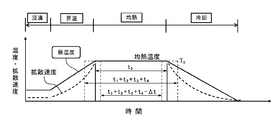
- FIG. 1 schematically illustrates the heat pattern of each zone.
- the plate temperature changes as shown by the solid line in FIG. 1, the actual diffusion amount is a function of exp (1 / T), so the diffusion amount (diffusion rate) per unit time during temperature rise and cooling is It looks like a dashed line.
- the constant holding temperature T 0 (K) in the above formula (1) can be set to any temperature in the temperature range where the diffusion of Fe atoms proceeds in Zn (ie, the formation reaction of ⁇ phase proceeds).
- a method for deriving the formula (1) will be disclosed by taking as an example a case where the soaking temperature in the soaking zone (soaking temperature of the steel plate) is adopted as T 0 .
- an expression giving the diffusion coefficient D of Fe in Zn at each temperature is necessary.
- the data of transition metals having the same atomic radius may be substituted. it can.
- substitutable elements include Cr, Mn, Co, Ni, and Cu in the fourth to sixth groups of the periodic table (Fe is a group 8 element).
- Q Ni 28919 cal / mol
- the diffusion coefficient is expressed as follows.
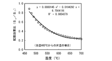
- FIG. 2 shows changes in the diffusion coefficient ratio (vs 460 ° C.) at each temperature based on the diffusion coefficient at 460 ° C. (generally corresponding to the bath temperature) (the coefficient at 460 ° C. is 1) (calculation of Ni). Value instead).
- a typical bath temperature of 460 ° C. in the plating line is used as a reference, but a diffusion coefficient ratio based on a standard bath temperature may be adopted according to the production line.
- Figure 3 represents the temperature change of the ratio of the diffusion amount S a and Hitoshi addicting diffusion amount S T in warm determined from FIG.
- the converted passage time t 1 (sec) of the immersion zone is converted from the curve of FIG. 2 by the ratio of the diffusion coefficient at the soaking temperature (T 0 converted to ° C.) and the diffusion coefficient at 460 ° C.
- T 0 converted to ° C. the ratio of the diffusion coefficient at the soaking temperature
- T 0 converted to ° C. the diffusion coefficient at 460 ° C.
- the following equation (3) is obtained.
- t 1 [immersion time] / (9.9904 ⁇ 10 ⁇ 32 ⁇ [soaking temperature] 11.656 ) (3)
- the unit of time is sec, and the unit of soaking temperature is ° C. (the above T 0 is converted to ° C.).
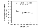
- FIG. 5 illustrates the relationship between the theoretical-actual deviation and the soaking temperature due to the delay time until the start of the ⁇ phase growth.
- the deviation (delay time) ⁇ t can be calculated by representing each plot with an approximate straight line.
- This ⁇ t is expressed as a function of T 0 .
- T 0 is set to the soaking temperature in the soaking zone
- ⁇ t is expressed by the following equation (4).
- ⁇ t ⁇ 0.000069 ⁇ [soaking temperature] +9.4993 (4)
- the unit of ⁇ t is sec, and the unit of soaking temperature is ° C. (the above T 0 is converted to ° C.).
- Prediction formula ⁇ TOTAL V (T 0 ) ⁇ (t 0 ⁇ t) 1/2 (1)
- the value determined by the equation (7) is substituted for V (T 0 ) of the above, the total value of the aforementioned t 1 + t 2 + t 3 + t 4 is substituted for t 0, and the value determined by the equation (4) is substituted for ⁇ t.
- the total average thickness ⁇ TOTAL ( ⁇ m) of the ⁇ phase generated by the heat pattern through which the steel plate passes through each zone can be predicted.
- the prediction formula is the following formula (8).
- ⁇ TOTAL 10822 ⁇ exp ( ⁇ 16771 / (1.987 ⁇ T 0 )) ⁇ (t 0 ⁇ t) 1/2 (8)
- the length of the immersion zone (the immersion distance of the steel plate in the hot dip galvanizing bath) is 7.5 m
- the length of the heating zone is 8.9 m
- the length of the soaking zone is 7 m
- the length of the cooling zone is The present invention will be described by taking a continuous alloyed hot-dip galvanized steel sheet production line of 10 m as an example.
- the “converted soaking time correction” in FIG. 7 means that ⁇ t is introduced into the equation (1) (the same applies to FIGS. 8, 9 and 12 described later).
- the actual measurement value is the average thickness of the ⁇ phase measured by SEM observation of the cross section of the plating layer (the same applies hereinafter).
- the calculated ⁇ layer thickness (predicted value) obtained from the prediction formula (8) of the ⁇ layer thickness derived from laboratory data (low carbon steel, the coating amount is 60 g / m 2 ).
- FIG. 8 exemplifies the relationship between the calculated value (predicted value) and the actual value according to the equation (8) for steel sheets having various coating adhesion amounts including not only low carbon steel but also IF (Interstitial Free) steel. In this case, the variation in the relationship between the predicted value and the actual value according to the equation (8) increases.
- FIG. 9 illustrates the relationship between the calculated value (predicted value) and the actual value obtained by properly using the formulas (8) and (9) according to the steel type.
- FIG. 10 exemplifies the relationship between the plating adhesion amount, the ⁇ phase thickness calculation value (predicted value), and the deviation amount of the actual value when the soaking temperature is less than 590 ° C.
- FIG. 11 illustrates the relationship between the amount of plating adhesion, the calculated value of the ⁇ phase thickness (predicted value), and the amount of deviation between the actual values when the soaking temperature is 590 ° C. or higher.
- Low carbon steel and medium carbon steel were calculated using equation (8), and IF steel was calculated using equation (9). Then, the following formulas (10) and (12) with the correction term added to the formula (8) and the following formulas (11) and (13) with the correction term added to the formula (9) were obtained. These correction terms correspond to the function g in the above equation (1) ′.
- FIG. 12 exemplifies the relationship between the calculated value (predicted value) and the actual value obtained by correcting the influence of the steel type and the plating adhesion amount using the expressions (10) to (13).
- Figure 13 illustrates the relationship between the simple soaking time following applying the t 3 to (8) (14) values calculated by the equation (predicted value) and the actual value before adding the correction .
- ⁇ TOTAL 10822 ⁇ exp (-16671 / (1.987 ⁇ T 0 )) ⁇ t 3 1/2 (14)
- FIG. 8, FIG. 9, and FIG. 12 it can be seen that the prediction accuracy improves as the correction is carefully performed.
- alloyed hot dip galvanized steel sheets were produced under various conditions in the above-mentioned continuous alloying hot dip coating line.
- the data is shown in Table 1 (a), Table 1 (b), Table 2 (a), and Table 2 (b).
- “LS” is the line speed
- “TV” is the product of the plate thickness of the base steel sheet and the line speed.
- the investigation of powdering is performed by first bending 6t (180 °), then bending back (120 °) and observing the bent part, and the amount of powdering, that is, the amount of the powdered plating layer dropped off According to the rating, it was classified into 5 grades with a rating of 1-5. The lower the score, the lower the score. Further, as the alloying progresses, the ⁇ layer grows thicker, so that the amount of powdering tends to increase, and the score tends to decrease.
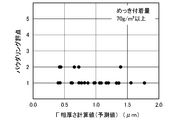
- FIG. 14, FIG. 15 and FIG. 16 show the relationship between the calculated ⁇ layer thickness (predicted value) obtained using the above equations (10) to (13) and the powdering score for medium and low carbon steels. These three figures are arranged according to the amount of plating adhesion. As described above, by classifying according to the plating adhesion amount, a correlation between the calculated ⁇ layer thickness (predicted value) obtained using the equations (10) to (13) and the powdering score can be obtained. The powdering score can be predicted based on such correlation. In the case of medium / low carbon steel, when the coating weight is 70 g / m 2 or more, it is difficult to obtain a high powdering score even if the ⁇ phase thickness is reduced (FIG. 16).
- the amount of powdering that is practically acceptable varies depending on the amount of alloyed hot dip galvanized deposit and the degree of press forming on which the alloyed hot dip galvanized steel sheet is provided. For this reason, even if the above-mentioned powdering scores are the same, the applicability determination (pass / fail determination) is not uniform depending on the application.
- powdering evaluations determined according to a certain standard according to the amount of plating adhesion are illustrated in the table as ⁇ (good) and x (bad).
- the figure numbers in FIG. 13, FIG. 8, FIG. 9, and FIG. 12 described in the column of [ Gamma] TOTAL calculation means that they are data used for the calculation values of the corresponding figures.
Landscapes
- Chemical & Material Sciences (AREA)
- Chemical Kinetics & Catalysis (AREA)
- Engineering & Computer Science (AREA)
- Materials Engineering (AREA)
- Mechanical Engineering (AREA)
- Metallurgy (AREA)
- Organic Chemistry (AREA)
- Physics & Mathematics (AREA)
- Oil, Petroleum & Natural Gas (AREA)
- Thermal Sciences (AREA)
- Coating With Molten Metal (AREA)
Abstract
【課題】合金化溶融亜鉛めっき鋼板のΓ相生成量を簡便且つ精度良く予測する。 【解決手段】溶融亜鉛めっき浴浸漬ゾーン、昇温ゾーン、均熱ゾーン、冷却ゾーンを上記の順に有する溶融めっきラインで合金化溶融亜鉛めっき鋼板を製造する際にめっき層中に形成されるΓ(キャピタルガンマ)相の生成量を予測する方法であって、上記全ゾーンを通過することにより生成するΓ相のトータル平均厚さΓTOTAL(μm)を、下記(1)式によって予測する合金化溶融亜鉛めっき鋼板のΓ相生成量予測方法。 ΓTOTAL=V(T0)×(t0-Δt)1/2 …(1) ここで、V(T0)はΓ相厚さ成長速度(μm/sec1/2)、t0は換算均熱時間(sec)、Δtはめっき浴浸漬初期のΓ相の生成遅れに起因する遅延時間(sec)である。
Description
本発明は、連続溶融めっきラインで合金化溶融亜鉛めっき鋼板を製造するにおいて、めっき層に生成するΓ(キャピタルガンマ)相の生成量を、製造条件から、反応速度論に基づく予測式によって予測する方法に関する。また、その予測方法を用いた合金化溶融亜鉛めっき鋼板の製造方法に関する。
合金化溶融亜鉛めっき鋼板は、めっき層がΓ相、δ1相、ζ相などの鉄-亜鉛系合金相で構成されていることから、亜鉛めっき鋼板の一種でありながら、プレス成形性(めっきの金型かじりが少ない)や、スポット溶接性が良好であるという特長を有する。しかし、合金化が過度に進行すると脆いΓ相(Fe3Zn10)の厚さが増大し、めっき鋼板加工時(曲げ、曲げ戻し、プレス加工、特に絞り加工時、フォーミング加工等)にめっき層が粉状に脱落する「パウダリング現象」が起こり、プレス金型の清掃・手入れの手間を要し、ひどい場合にはプレス時の加工割れや疵の原因にもなる。まためっき層の脱落は耐食性の低下にも繋がることから、合金化溶融亜鉛めっき鋼板の品質管理の上で、このΓ相の成長の度合いを把握、コントロールすることが重要であり、これまで鉄鋼・自動車各社で種々の方法が開発・実施されてきた。その方法として、大きく以下のようなものがある。
[1]X線回折装置等のセンサーを設置することによりめっき層の合金化度をオンラインあるいはオフラインで測定する方法。
[2]鋼板からサンプル板を採取しめっき層の分析により層中のFe含有量を測定する方法。
[3]サンプル板に実際に簡易な加工(曲げ、曲げ戻し等)を施すことによりめっき層の脱落度合いを把握する方法。
これらの方法で合金化度を測定、把握し、その結果に基づいて合金化処理設備(例えばガスバーナー、誘導加熱、またはそれらを併用した加熱手段を有する合金化炉)の制御および通板速度の制御が行われる。一例として特許文献1の技術が挙げられる。
[2]鋼板からサンプル板を採取しめっき層の分析により層中のFe含有量を測定する方法。
[3]サンプル板に実際に簡易な加工(曲げ、曲げ戻し等)を施すことによりめっき層の脱落度合いを把握する方法。
これらの方法で合金化度を測定、把握し、その結果に基づいて合金化処理設備(例えばガスバーナー、誘導加熱、またはそれらを併用した加熱手段を有する合金化炉)の制御および通板速度の制御が行われる。一例として特許文献1の技術が挙げられる。
上記の[1]~[3]の方法は工業的に確立された技術である。しかし、[1]は高価なセンサーが必要で設備費が膨大となり、[2]、[3]はサンプリングによる抜き取り検査であるために全長測定のオンライン測定に比べて安心度は低下し、かつ人手がかかるという問題がある。
本発明は、合金化溶融亜鉛めっき鋼板のΓ相生成量を、高価なセンサーが不要で、作業者の労力負荷が低く、ライン速度や鋼板温度(合金化炉の温度設定)等の基本的な操業パラメータによって簡便かつ実用的に有用な高精度で予測する方法を提供しようというものである。
上記目的を達成するために、本発明では、溶融亜鉛めっき浴浸漬ゾーン、めっき層の合金化処理における昇温ゾーン、同均熱ゾーン、同冷却ゾーンを上記の順に有する溶融めっきラインで合金化溶融亜鉛めっき鋼板を製造するに際し、上記全ゾーンを通過することによりめっき層中に生成するΓ(キャピタルガンマ)相のトータル平均厚さΓTOTAL(μm)を下記(1)式によって計算することにより予測する、合金化溶融亜鉛めっき鋼板のΓ相生成量予測方法が提供される。
ΓTOTAL=V(T0)×(t0-Δt)1/2 …(1)
ここで、
V(T0):めっき層形成後の溶融亜鉛めっき鋼板を一定温度T0(K)で保持したときのΓ相厚さ成長速度(μm/sec1/2)、
t0:各ゾーン通過時間と各ゾーン通過中の刻々の板温での拡散係数から求まるΓ相のトータル生成量を、一定温度T0(K)で保持したとしてT0(K)での拡散係数から算出するための換算均熱時間(sec)、
Δt:めっき浴浸漬初期のΓ相の生成遅れに起因する遅延時間(sec)、
である。
ΓTOTAL=V(T0)×(t0-Δt)1/2 …(1)
ここで、
V(T0):めっき層形成後の溶融亜鉛めっき鋼板を一定温度T0(K)で保持したときのΓ相厚さ成長速度(μm/sec1/2)、
t0:各ゾーン通過時間と各ゾーン通過中の刻々の板温での拡散係数から求まるΓ相のトータル生成量を、一定温度T0(K)で保持したとしてT0(K)での拡散係数から算出するための換算均熱時間(sec)、
Δt:めっき浴浸漬初期のΓ相の生成遅れに起因する遅延時間(sec)、
である。
前記(1)式の換算均熱時間t0には、各ゾーンの通過時間と各ゾーン通過中の刻々の板温での拡散係数から求まるΓ相生成量についての換算通過時間t1~t4の総和t1+t2+t3+t4を代入することができる。
ここで、
t1:溶融めっき浴浸漬ゾーン通過中のΓ相生成量を一定温度T0(K)で保持したとして算出するための換算通過時間(sec)、
t2:めっき層の合金化処理における昇温ゾーン通過中のΓ相生成量を一定温度T0(K)で保持したとして算出するための換算通過時間(sec)、
t3:めっき層の合金化処理における均熱ゾーン通過中のΓ相生成量を一定温度T0(K)で保持したとして算出するための換算通過時間(sec)、
t4:めっき層の合金化処理における冷却ゾーン通過中のΓ相生成量を一定温度T0(K)で保持したとして算出するための換算通過時間t4(sec)、
である。
この場合、(1)式は次のようになる。
ΓTOTAL=V(T0)×(t1+t2+t3+t4-Δt)1/2 …(1)
以下、特に断らない限り、「浸漬ゾーン」は溶融めっき浴浸漬ゾーン、「昇温ゾーン」はめっき層の合金化処理における昇温ゾーン、「均熱ゾーン」はめっき層の合金化処理における均熱ゾーン、「冷却ゾーン」はめっき層の合金化処理における冷却ゾーンをそれぞれ意味する。
ここで、
t1:溶融めっき浴浸漬ゾーン通過中のΓ相生成量を一定温度T0(K)で保持したとして算出するための換算通過時間(sec)、
t2:めっき層の合金化処理における昇温ゾーン通過中のΓ相生成量を一定温度T0(K)で保持したとして算出するための換算通過時間(sec)、
t3:めっき層の合金化処理における均熱ゾーン通過中のΓ相生成量を一定温度T0(K)で保持したとして算出するための換算通過時間(sec)、
t4:めっき層の合金化処理における冷却ゾーン通過中のΓ相生成量を一定温度T0(K)で保持したとして算出するための換算通過時間t4(sec)、
である。
この場合、(1)式は次のようになる。
ΓTOTAL=V(T0)×(t1+t2+t3+t4-Δt)1/2 …(1)
以下、特に断らない限り、「浸漬ゾーン」は溶融めっき浴浸漬ゾーン、「昇温ゾーン」はめっき層の合金化処理における昇温ゾーン、「均熱ゾーン」はめっき層の合金化処理における均熱ゾーン、「冷却ゾーン」はめっき層の合金化処理における冷却ゾーンをそれぞれ意味する。
(1)式のT0は、例えば均熱ゾーンにおける均熱温度(鋼板の均熱保持温度)の値とすることができる。この場合、上記の換算通過時間t3は、合金化炉の均熱時間をそのまま適用すればよい。適用鋼種ごとにV(T0)が異なる複数の(1)式を用意し、鋼種に応じてそれらの(1)式を使い分けることができる。(1)式に代え、めっき付着量d(g/m2)の関数gで表される補正項を付加した下記(1)’式を適用することがより好ましい。
ΓTOTAL=V(T0)×(t0-Δt)1/2 +g(d) …(1)’
ΓTOTAL=V(T0)×(t0-Δt)1/2 +g(d) …(1)’
また本発明では、めっき層中に形成されるΓ相生成量の上限規制値を設定し、上記のΓ相生成量予測方法により予測されるΓ相生成量が前記上限規制を満たすように、ライン速度、均熱ゾーンにおける均熱温度の少なくとも一方を制御する合金化溶融亜鉛めっき鋼板の製造方法が提供される。
本発明によれば、簡便な方法で精度良く合金化溶融亜鉛めっき鋼板に形成される脆いΓ相の生成量を予測することができる。高価なセンサーによる計測も必要とせず、ライン速度や鋼板温度(合金化炉の温度設定)等の基本的な操業パラメータによって予測できるため、既存の種々の連続合金化溶融めっきラインでの実施も容易である。従って本発明は、合金化溶融亜鉛めっき鋼板のきめ細かな品質管理に極めて有用である。
従来、合金化溶融亜鉛めっき鋼板の製造においてΓ相の生成量の予測方法は種々試みられてきたが、高価なセンサーによる測定値をフィードバックしない限り、予測精度を十分に向上させることは難しかった。発明者の検討によれば、予測精度の向上が難しい原因として、以下のことが考えられる。一般的に、合金化溶融亜鉛めっき鋼板の操業で形成される合金相の予測に関しては、合金化処理炉での到達(目標)温度とその時間(均熱時間)で整理することが多いが、実際にはめっき浴に浸漬している間に合金化反応は始まっており、合金化処理設備での昇温過程、冷却過程においても反応は進行する。特に、刻々と変わる昇温・冷却時の原子の拡散量の計算が煩雑であり、これを考慮した数式化ができていなかった。また、溶融亜鉛めっき浴中には微量のAlが添加されることが多く、この影響でめっき層/素地鋼板界面には初期にバリアーができ、亜鉛めっき層中へのFe原子の拡散開始が遅れるため、予測値と現実に差があった。
本発明は、これらの点を考慮し、反応速度論に基づく理論式をベースとして補正を加えた予測式を設け、それによってΓ相の生成量を予測する。その予測式は、浸漬ゾーン、昇温ゾーン、均熱ゾーン、冷却ゾーンの各過程を通過してΓ相のトータル平均厚さがΓTOTAL(μm)になる場合において、仮に、一定温度T0(K)で上記全過程を保持したとすれば、同じ量のΓ相が生じるために必要な均熱時間はどの程度になるか、という換算均熱時間t0(sec)を用いて整理した下記(1)式に示すものである。
ΓTOTAL=V(T0)×(t0-Δt)1/2 …(1)
ここで、V(T0)はめっき層形成後の溶融亜鉛めっき鋼板を一定温度T0(K)で保持したときのΓ相厚さ成長速度(μm/sec1/2)である。t0は、各ゾーン通過時間と各ゾーン通過中の刻々の板温での拡散係数から求まるΓ相のトータル生成量を、一定温度T0(K)で保持したとしてT0(K)での拡散係数から算出するための換算均熱時間(sec)である。Δtは、めっき浴浸漬初期のΓ相の生成遅れに起因する遅延時間(sec)である。
ΓTOTAL=V(T0)×(t0-Δt)1/2 …(1)
ここで、V(T0)はめっき層形成後の溶融亜鉛めっき鋼板を一定温度T0(K)で保持したときのΓ相厚さ成長速度(μm/sec1/2)である。t0は、各ゾーン通過時間と各ゾーン通過中の刻々の板温での拡散係数から求まるΓ相のトータル生成量を、一定温度T0(K)で保持したとしてT0(K)での拡散係数から算出するための換算均熱時間(sec)である。Δtは、めっき浴浸漬初期のΓ相の生成遅れに起因する遅延時間(sec)である。
図1に、各ゾーンのヒートパターンを模式的に例示する。板温度の変化は図1の実線のようになるが、実際の拡散量はexp(1/T)の関数であるため、昇温中、冷却中の単位時間当たりの拡散量(拡散速度)は破線のようになる。
上記(1)式における一定保持温度T0(K)はZn中でFe原子の拡散が進行する(すなわちΓ相の生成反応が進行する)温度域における任意の温度に設定することができる。以下に、均熱ゾーンの均熱温度(鋼板の均熱保持温度)をT0として採用した場合を例に挙げて、(1)式を導く手法を開示する。換算均熱時間t0を求めるためには各温度でのZn中のFeの拡散係数Dを与える式が必要であるが、便宜的に原子半径が同程度の遷移金属のデータによって代用することもできる。代用可能な元素として周期表第4周期第6~11族にあるCr、Mn、Co、Ni、Cuが挙げられる(Feは同8族元素)。今回は、Feと原子半径が近いNiの活性化エネルギー値(QNi=28919cal/mol)による代用を試みる。この場合、拡散係数は以下のように表される。
D=D0・exp(-QNi/(R・T)) …(0)
D:拡散係数(m2/sec)
D0:頻度因子
R:気体定数=1.987(cal/mol/K)
T:絶対温度(K)
QNi:活性化エネルギー=28919(cal/mol)
上記(1)式における一定保持温度T0(K)はZn中でFe原子の拡散が進行する(すなわちΓ相の生成反応が進行する)温度域における任意の温度に設定することができる。以下に、均熱ゾーンの均熱温度(鋼板の均熱保持温度)をT0として採用した場合を例に挙げて、(1)式を導く手法を開示する。換算均熱時間t0を求めるためには各温度でのZn中のFeの拡散係数Dを与える式が必要であるが、便宜的に原子半径が同程度の遷移金属のデータによって代用することもできる。代用可能な元素として周期表第4周期第6~11族にあるCr、Mn、Co、Ni、Cuが挙げられる(Feは同8族元素)。今回は、Feと原子半径が近いNiの活性化エネルギー値(QNi=28919cal/mol)による代用を試みる。この場合、拡散係数は以下のように表される。
D=D0・exp(-QNi/(R・T)) …(0)
D:拡散係数(m2/sec)
D0:頻度因子
R:気体定数=1.987(cal/mol/K)
T:絶対温度(K)
QNi:活性化エネルギー=28919(cal/mol)
まず、昇温ゾーンの換算通過時間t2(sec)と冷却ゾーンの換算通過時間t4(sec)を求める。
図2は、460℃(概ね浴温に相当)での拡散係数をベース(460℃の係数を1)として各温度の拡散係数比(vs460℃)の変化を表したものである(Niの計算値で代用)。ここでは、当該めっきラインでの代表的な浴温460℃を基準としているが、製造ラインに応じて標準的な浴温を基準とした拡散係数比を採用すればよい。
図3は、図2より求めた昇温中の拡散量Saと均熱中の拡散量STとの比の温度変化を表している。図3のプロットの2次曲線近似式より、昇温・冷却中の拡散量の換算通過温時間t2(sec)、t4(sec)は下記(2a)式、(2b)式のようになる。
t2=[昇温ゾーン通過時間]×(0.0000145×[均熱温度]2-0.01943×[均熱温度]+6.7564) …(2a)
t4=[冷却ゾーン通過時間]×(0.0000145×[均熱温度]2-0.01943×[均熱温度]+6.7564) …(2b)
ただし、(2a)式、(2b)式において、時間の単位はsec、均熱温度の単位は℃(上記T0を℃に換算したもの)である。
図2は、460℃(概ね浴温に相当)での拡散係数をベース(460℃の係数を1)として各温度の拡散係数比(vs460℃)の変化を表したものである(Niの計算値で代用)。ここでは、当該めっきラインでの代表的な浴温460℃を基準としているが、製造ラインに応じて標準的な浴温を基準とした拡散係数比を採用すればよい。
図3は、図2より求めた昇温中の拡散量Saと均熱中の拡散量STとの比の温度変化を表している。図3のプロットの2次曲線近似式より、昇温・冷却中の拡散量の換算通過温時間t2(sec)、t4(sec)は下記(2a)式、(2b)式のようになる。
t2=[昇温ゾーン通過時間]×(0.0000145×[均熱温度]2-0.01943×[均熱温度]+6.7564) …(2a)
t4=[冷却ゾーン通過時間]×(0.0000145×[均熱温度]2-0.01943×[均熱温度]+6.7564) …(2b)
ただし、(2a)式、(2b)式において、時間の単位はsec、均熱温度の単位は℃(上記T0を℃に換算したもの)である。
次に、浸漬ゾーンの換算通過時間t1(sec)については、図2の曲線から均熱温度(T0を℃に換算した値)での拡散係数と460℃での拡散係数の比により換算可能であり、具体的には下記(3)式のようになる。
t1=[浸漬時間]/(9.9904×10-32×[均熱温度]11.656) …(3)
ただし、(3)式において、時間の単位はsec、均熱温度の単位は℃(上記T0を℃に換算したもの)である。
t1=[浸漬時間]/(9.9904×10-32×[均熱温度]11.656) …(3)
ただし、(3)式において、時間の単位はsec、均熱温度の単位は℃(上記T0を℃に換算したもの)である。
上記(2a)式、(2b)式、(3)式から、各ゾーンを通しての換算均熱時間t0(sec)=t1+t2+t3+t4が求まる。t3には、ここでは均熱時間をそのまま代入すればよい。
次に、Γ相の成長速度式の導入を試みる。合金化反応は、熱による原子の拡散に起因するものであるから、反応速度論に基づく換算均熱時間の平方根とΓ相厚さの関係は原点を通る直線となるはずである。そこで、実験室の合金化溶融亜鉛めっき試験装置を用いて、鋼板を溶融亜鉛めっき浴に浸漬したのちに引き上げ、続いて、赤外線加熱装置に投入して種々の均熱温度と均熱時間により加熱したサンプルを作製した。このサンプルを調査して、浸漬時間、昇温時間、冷却時間の換算を行い、換算均熱時間の平方根とΓ相厚さの関係を作図した。図4にその結果を示す。しかし、原点を通る直線を作図した場合に、特に短時間側のプロットが理論直線から大きくズレてくる結果となった。
図4の実際のプロットにおいて換算均熱時間の平方根の値が小さい領域ほど、Γ相の成長量が小さい(ズレが大きい)ことがわかる。これはΓ相生成がめっき浴への浸漬直後には起こらないことを意味していると考えられる。すなわち、浴浸漬直後の数秒間は、Fe-Al系化合物およびδ1相、ζ相のみが成長し、これらの相がある程度成長した後にΓ相の成長が始まるため、初期の数秒間(5~7秒)はΓ相成長反応には寄与していないことになる。ちなみに、長時間側ほどプロットが直線に乗るのは、横軸が時間の平方根であり、初期数秒間のズレが作図上小さくなり目立たないためである。
図4の実際のプロットにおいて換算均熱時間の平方根の値が小さい領域ほど、Γ相の成長量が小さい(ズレが大きい)ことがわかる。これはΓ相生成がめっき浴への浸漬直後には起こらないことを意味していると考えられる。すなわち、浴浸漬直後の数秒間は、Fe-Al系化合物およびδ1相、ζ相のみが成長し、これらの相がある程度成長した後にΓ相の成長が始まるため、初期の数秒間(5~7秒)はΓ相成長反応には寄与していないことになる。ちなみに、長時間側ほどプロットが直線に乗るのは、横軸が時間の平方根であり、初期数秒間のズレが作図上小さくなり目立たないためである。
図5に、このΓ相成長開始までの遅れ時間による理論-実績のズレと均熱温度の関係を例示する。このように各プロットを近似直線で表すことにより上記ズレ(遅延時間)Δtを算出することができる。このΔtは上記T0の関数として表される。ここではT0を均熱ゾーンの均熱温度に設定しているので、Δtは下記(4)式のようになる。
Δt=-0.0069×[均熱温度]+9.4993 …(4)
ただし、(4)式において、Δtの単位はsec、均熱温度の単位は℃(上記T0を℃に換算したもの)である。
Δt=-0.0069×[均熱温度]+9.4993 …(4)
ただし、(4)式において、Δtの単位はsec、均熱温度の単位は℃(上記T0を℃に換算したもの)である。
次に、図4の直線からのズレを補正し、各プロットが図4の直線上に乗るものとし、この図4の各直線(均熱温度毎)の傾き(μm/sec1/2)の対数と均熱温度の絶対温度(K)の逆数の関係をグラフ化すると、図6のようになる。図6の直線関係からΓ相成長速度の対数logVと絶対温度の逆数1/Tの関係を求めると下記(5)となる。
logV=-3643×(1/T)+4.0343 …(5)
アレニウスのプロットはV=A・exp(-Q/(R・T))の形になるから、この式の両辺を対数にすると、lnV=ln(A・exp(-Q/(R・T)))=lnA-Q/(R・T)となり、これを自然対数から常用対数に変換(係数2.303)し、1/Tの項を分離すると、
logV=logA-(1/2.303)×(Q/(R・T))
=logA-(Q/(2.303×R))×(1/T) …(6)
となる。ここで、上の(6)式は(5)式と同じ形になるので、
logA=4.0343より、A=104.0343=10822、
Q/(2.303×R)=3643より、Q=16671(cal/mol)、
がそれぞれ求まる。
よって、温度T(K)におけるΓ相厚さ成長速度V(T)(μm/sec1/2)は下記(7)式のようになる。
V(T)=10822×exp(-16671/(R・T)) …(7)
logV=-3643×(1/T)+4.0343 …(5)
アレニウスのプロットはV=A・exp(-Q/(R・T))の形になるから、この式の両辺を対数にすると、lnV=ln(A・exp(-Q/(R・T)))=lnA-Q/(R・T)となり、これを自然対数から常用対数に変換(係数2.303)し、1/Tの項を分離すると、
logV=logA-(1/2.303)×(Q/(R・T))
=logA-(Q/(2.303×R))×(1/T) …(6)
となる。ここで、上の(6)式は(5)式と同じ形になるので、
logA=4.0343より、A=104.0343=10822、
Q/(2.303×R)=3643より、Q=16671(cal/mol)、
がそれぞれ求まる。
よって、温度T(K)におけるΓ相厚さ成長速度V(T)(μm/sec1/2)は下記(7)式のようになる。
V(T)=10822×exp(-16671/(R・T)) …(7)
上記した(1)式で示される予測式
ΓTOTAL=V(T0)×(t0-Δt)1/2 …(1)
のV(T0)に(7)式により定まる値を代入し、t0に前述のt1+t2+t3+t4の合計値を代入し、Δtに(4)式により定まる値を代入することによって、上記各ゾーンを鋼板が通過するヒートパターンで生成するΓ相のトータル平均厚さΓTOTAL(μm)を予測することができる。
ここでの例では、予測式は下記(8)式となる。
ΓTOTAL=10822×exp(-16671/(1.987×T0))×(t0-Δt)1/2 …(8)
ΓTOTAL=V(T0)×(t0-Δt)1/2 …(1)
のV(T0)に(7)式により定まる値を代入し、t0に前述のt1+t2+t3+t4の合計値を代入し、Δtに(4)式により定まる値を代入することによって、上記各ゾーンを鋼板が通過するヒートパターンで生成するΓ相のトータル平均厚さΓTOTAL(μm)を予測することができる。
ここでの例では、予測式は下記(8)式となる。
ΓTOTAL=10822×exp(-16671/(1.987×T0))×(t0-Δt)1/2 …(8)
以下、浸漬ゾーンの長さ(溶融亜鉛めっき浴中における鋼板の浸漬距離)が7.5m、昇温ゾーンの長さが8.9m、均熱ゾーンの長さが7m、冷却ゾーンの長さが10mである連続合金化溶融亜鉛めっき鋼板製造ラインを例に、本発明を説明する。
上記の各式は低炭素鋼を用いて活性化エネルギーQを求めたものである。低炭素鋼および中炭素鋼では、Q=16671(cal/mol)で求めた(8)式で十分な相関がとれる。
図7に、めっき付着量が一定範囲にある低炭素鋼について(8)式による計算値(予測値)と実測値の関係を例示する。図7中の「換算均熱時間補正」とは(1)式中に-Δtを導入していることを意味する(後述図8、9、12において同じ)。なお、実測値は、めっき層の断面をSEM観察することによって測定したΓ相の平均厚さである(以下において同じ)。図7からわかるように、実験室データ(低炭素鋼、めっき付着量は60g/m2)を元に導き出されたΓ層厚の予測式(8)によって求めた計算Γ層厚さ(予測値)は、実際のΓ層厚さと高い相関がある。
図8に、低炭素鋼のみならず、IF(Interstitial Free)鋼を含む種々のめっき付着量の鋼板について(8)式による計算値(予測値)と実績値の関係を例示する。この場合には、(8)式による予測値と実績値の関係におけるバラツキが大きくなる。
上記の各式は低炭素鋼を用いて活性化エネルギーQを求めたものである。低炭素鋼および中炭素鋼では、Q=16671(cal/mol)で求めた(8)式で十分な相関がとれる。
図7に、めっき付着量が一定範囲にある低炭素鋼について(8)式による計算値(予測値)と実測値の関係を例示する。図7中の「換算均熱時間補正」とは(1)式中に-Δtを導入していることを意味する(後述図8、9、12において同じ)。なお、実測値は、めっき層の断面をSEM観察することによって測定したΓ相の平均厚さである(以下において同じ)。図7からわかるように、実験室データ(低炭素鋼、めっき付着量は60g/m2)を元に導き出されたΓ層厚の予測式(8)によって求めた計算Γ層厚さ(予測値)は、実際のΓ層厚さと高い相関がある。
図8に、低炭素鋼のみならず、IF(Interstitial Free)鋼を含む種々のめっき付着量の鋼板について(8)式による計算値(予測値)と実績値の関係を例示する。この場合には、(8)式による予測値と実績値の関係におけるバラツキが大きくなる。
そこで次に、鋼種による補正を試みる。低炭素鋼ベースのTi、Nb添加鋼(IF鋼)の場合、粒界にはC、N、B等の侵入型の固溶原子がほとんど存在しない。亜鉛めっきの合金化処理は600℃以下の比較的低温の熱処理であるため、素地鋼板からのFe原子の供給は粒界拡散に負うところが大きい。従って、粒界に存在するC、NやB等の侵入型原子が少ないIF鋼は、Fe原子の粒界拡散が低炭素鋼や中炭素鋼に比べて容易であり、その結果としてめっき層へのFeの供給速度が大きくなると考えられる。このため、鋼種による補正は活性化エネルギーQを小さくすることによって行うことが妥当である。今回、IF鋼については(8)式の予測値と実測値の比較から逆算して、IF鋼の活性化エネルギーQを低炭素鋼より7%程度小さく見積って(8)式を補正した下記(9)式を適用することで、IF鋼についても良好な相関を得ることができた。
ΓTOTAL=10822×exp(-15500/(1.987×T0))×(t0-Δt)1/2 …(9)
図9に、鋼種に応じて(8)式と(9)式を使い分けることによって得た計算値(予測値)と実績値の関係を例示する。
ΓTOTAL=10822×exp(-15500/(1.987×T0))×(t0-Δt)1/2 …(9)
図9に、鋼種に応じて(8)式と(9)式を使い分けることによって得た計算値(予測値)と実績値の関係を例示する。
次に、めっき付着量による補正を試みる。同じ温度、時間の合金化反応であっても、亜鉛めっき付着量が多い場合は素地鋼板から亜鉛めっき層中へ取り込むことが可能なFe原子の数は増大する(表層までFe原子が到達する時間が遅くなる)ため、素地鋼板との界面近傍に生成するΓ相の厚さは薄くなる。逆に、亜鉛めっき付着量が少ない場合はめっき層の表層部までFe原子が到達してしまうため、早期に素地鋼板との界面近傍のめっき層中におけるFe濃度が増大し、Γ相の生成厚さは厚くなる。データに基づいて種々検討したところ、例えば均熱温度590℃を境に区分すると、めっき付着量の影響が明確になった。
図10に、均熱温度590℃未満の場合のめっき付着量とΓ相厚さ計算値(予測値)と実績値のズレ量の関係を例示する。また図11に、均熱温度590℃以上の場合のめっき付着量とΓ相厚さ計算値(予測値)と実績値のズレ量の関係を例示する。低炭素鋼および中炭素鋼は(8)式、IF鋼は(9)式でそれぞれ計算値を求めた。そして(8)式に補正項を加えた下記(10)式と(12)式、および(9)式に補正項を加えた下記(11)式と(13)式を求めた。これらの補正項は、上記(1)’式の関数gに相当するものである。
図10に、均熱温度590℃未満の場合のめっき付着量とΓ相厚さ計算値(予測値)と実績値のズレ量の関係を例示する。また図11に、均熱温度590℃以上の場合のめっき付着量とΓ相厚さ計算値(予測値)と実績値のズレ量の関係を例示する。低炭素鋼および中炭素鋼は(8)式、IF鋼は(9)式でそれぞれ計算値を求めた。そして(8)式に補正項を加えた下記(10)式と(12)式、および(9)式に補正項を加えた下記(11)式と(13)式を求めた。これらの補正項は、上記(1)’式の関数gに相当するものである。
〔均熱温度590℃未満、低炭素鋼、中炭素鋼に適用する式〕
ΓTOTAL=10822×exp(-16671/(1.987×T0))×(t0-Δt)1/2+(47.4-[めっき付着量])×0.0108 …(10)
〔均熱温度590℃未満、IF鋼に適用する式〕
ΓTOTAL=10822×exp(-15500/(1.987×T0))×(t0-Δt)1/2+(47.4-[めっき付着量])×0.0108 …(11)
〔均熱温度590℃以上、低炭素鋼、中炭素鋼に適用する式〕
ΓTOTAL=10822×exp(-16671/(1.987×T0))×(t0-Δt)1/2+(51.8-[めっき付着量])×0.0277 …(12)
〔均熱温度590℃以上、IF鋼に適用する式〕
ΓTOTAL=10822×exp(-15500/(1.987×T0))×(t0-Δt)1/2+(51.8-[めっき付着量])×0.0277 …(13)
これらの式において、めっき付着量は片面当たりの付着量(g/m2)を意味する。
図12に、(10)式~(13)式を用いて鋼種の影響およびめっき付着量の影響を補正した計算値(予測値)と実績値の関係を例示する。
比較のため、図13に、補正を加える前の単純な均熱時間t3を(8)式に適用した下記(14)式により求めた計算値(予測値)と実績値の関係を例示する。
ΓTOTAL=10822×exp(-16671/(1.987×T0))×t3 1/2 …(14)
補正前の図13に対し、図8、図9、図12と、補正を入念に行うほど予測精度が向上することがわかる。
ΓTOTAL=10822×exp(-16671/(1.987×T0))×(t0-Δt)1/2+(47.4-[めっき付着量])×0.0108 …(10)
〔均熱温度590℃未満、IF鋼に適用する式〕
ΓTOTAL=10822×exp(-15500/(1.987×T0))×(t0-Δt)1/2+(47.4-[めっき付着量])×0.0108 …(11)
〔均熱温度590℃以上、低炭素鋼、中炭素鋼に適用する式〕
ΓTOTAL=10822×exp(-16671/(1.987×T0))×(t0-Δt)1/2+(51.8-[めっき付着量])×0.0277 …(12)
〔均熱温度590℃以上、IF鋼に適用する式〕
ΓTOTAL=10822×exp(-15500/(1.987×T0))×(t0-Δt)1/2+(51.8-[めっき付着量])×0.0277 …(13)
これらの式において、めっき付着量は片面当たりの付着量(g/m2)を意味する。
図12に、(10)式~(13)式を用いて鋼種の影響およびめっき付着量の影響を補正した計算値(予測値)と実績値の関係を例示する。
比較のため、図13に、補正を加える前の単純な均熱時間t3を(8)式に適用した下記(14)式により求めた計算値(予測値)と実績値の関係を例示する。
ΓTOTAL=10822×exp(-16671/(1.987×T0))×t3 1/2 …(14)
補正前の図13に対し、図8、図9、図12と、補正を入念に行うほど予測精度が向上することがわかる。
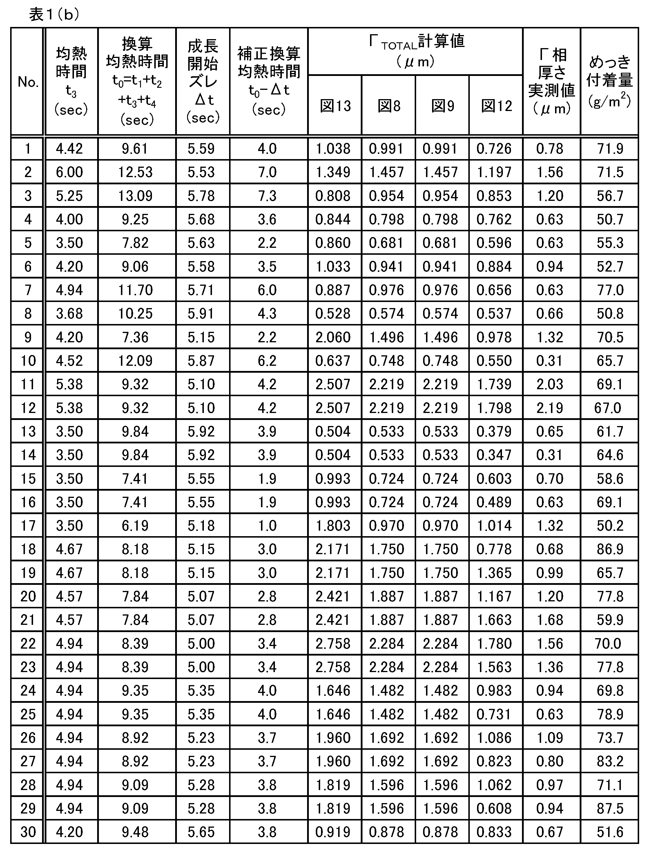
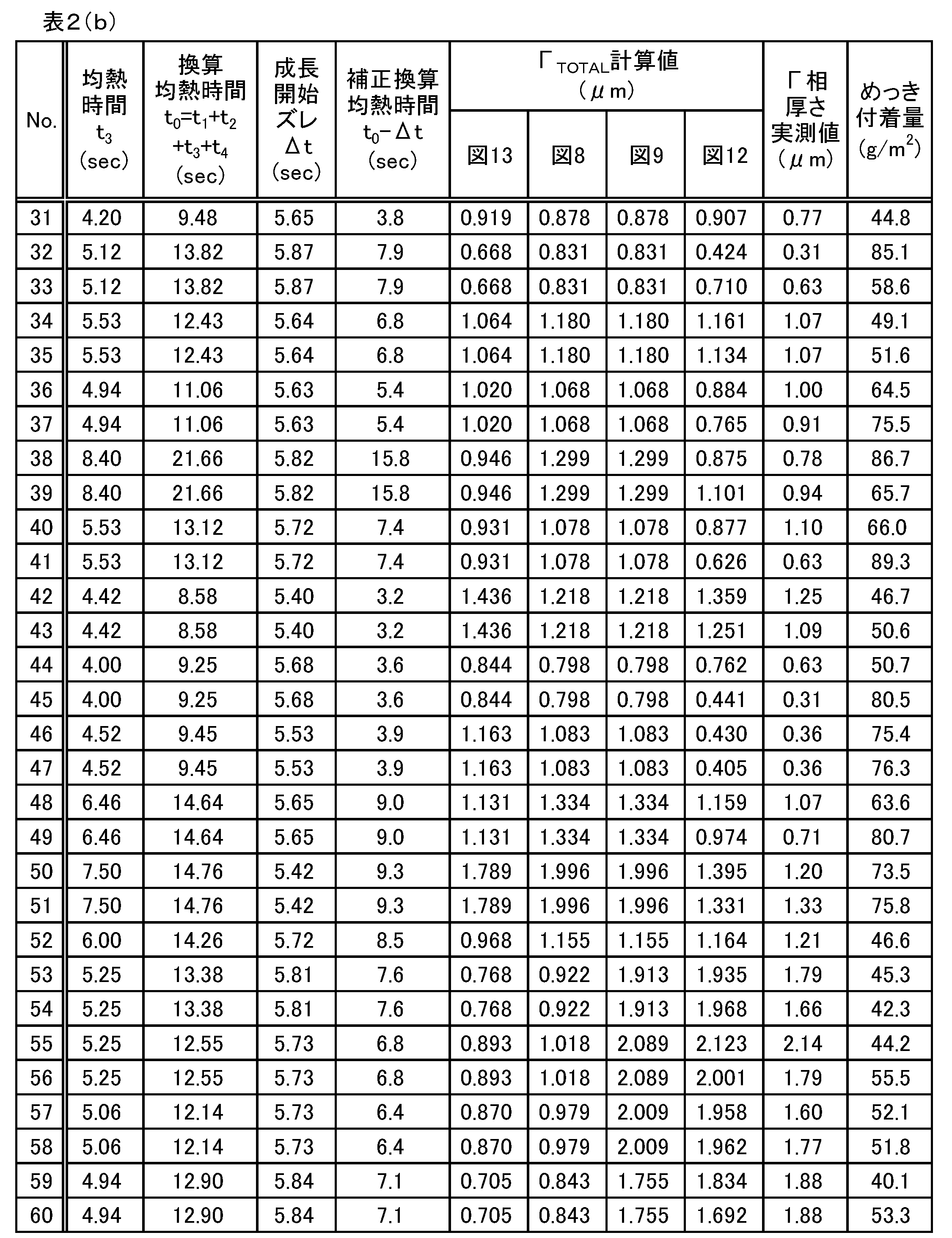
低炭素鋼、中炭素鋼、IF鋼を素地鋼板に用いて、前述の連続合金化溶融めっきラインにて種々の条件で合金化溶融亜鉛めっき鋼板を製造した。そのデータを表1(a)、表1(b)、表2(a)、表2(b)に示す。表中の「LS」はライン速度、「TV」は素地鋼板の板厚とライン速度の積である。
パウダリングの調査は、まず6t曲げ(180°)を行い、続いて曲げ戻し(120°)を行って曲げ加工部を観察し、パウダリング量、すなわち脱落した粉状のめっき層の量の多少に応じて評点1~5の5段階に分類した。脱落した粉状のめっき層の量が多いほど低い評点となる。また、合金化が進行するほどΓ層が厚く成長するためパウダリング量が増大しやすく、評点は低くなる傾向がある。
図14、図15、図16に、中・低炭素鋼について、上記(10)式~(13)式を用いて求めたΓ層厚計算値(予測値)とパウダリング評点の関係を示す。めっき付着量に応じてこれら3つの図に分けて整理した。このように、めっき付着量に応じて分類することにより、(10)式~(13)式を用いて求めたΓ層厚計算値(予測値)とパウダリング評点の相関が得られる。このような相関に基づいてパウダリング評点の予測も可能である。なお、中・低炭素鋼の場合、めっき付着量が70g/m2以上になるとΓ相厚さを低減しても高いパウダリング評点を得ることは難しい(図16)。
実用的に許容されるパウダリング発生量は、合金化溶融亜鉛めっきの付着量や合金化溶融亜鉛めっき鋼板が供されるプレス成形の加工度によって異なってくる。そのため、上述のパウダリング評点が同一でも、用途によって適用可否の判定(合否判定)は一様ではない。参考のため、ここでは、めっき付着量に応じて一定の基準によって判定したパウダリング評価を○(良好)および×(不良)で表中に例示した。
ΓTOTAL計算値の欄に記載の図13、図8、図9、図12の図番は、それぞれ対応する図の計算値に使用したデータであることを意味する。
ΓTOTAL計算値の欄に記載の図13、図8、図9、図12の図番は、それぞれ対応する図の計算値に使用したデータであることを意味する。


Claims (6)
- 溶融亜鉛めっき浴浸漬ゾーン、めっき層の合金化処理における昇温ゾーン、同均熱ゾーン、同冷却ゾーンを上記の順に有する溶融めっきラインで合金化溶融亜鉛めっき鋼板を製造するに際し、上記全ゾーンを通過することによりめっき層中に生成するΓ(キャピタルガンマ)相のトータル平均厚さΓTOTAL(μm)を下記(1)式によって予測する合金化溶融亜鉛めっき鋼板のΓ相生成量予測方法。
ΓTOTAL=V(T0)×(t0-Δt)1/2 …(1)
ここで、
V(T0):めっき層形成後の溶融亜鉛めっき鋼板を一定温度T0(K)で保持したときのΓ相厚さ成長速度(μm/sec1/2)、
t0:各ゾーン通過時間と各ゾーン通過中の刻々の板温での拡散係数から求まるΓ相のトータル生成量を、一定温度T0(K)で保持したとしてT0(K)での拡散係数から算出するための換算均熱時間(sec)、
Δt:めっき浴浸漬初期のΓ相の生成遅れに起因する遅延時間(sec)、
である。 - 前記(1)式の換算均熱時間t0には、各ゾーンの通過時間と各ゾーン通過中の刻々の板温での拡散係数から求まるΓ相生成量についての換算通過時間t1~t4の総和t1+t2+t3+t4が代入される請求項1に記載の合金化溶融亜鉛めっき鋼板のΓ相生成量予測方法。
ここで、
t1:溶融めっき浴浸漬ゾーン通過中のΓ相生成量を一定温度T0(K)で保持したとして算出するための換算通過時間(sec)、
t2:めっき層の合金化処理における昇温ゾーン通過中のΓ相生成量を一定温度T0(K)で保持したとして算出するための換算通過時間(sec)、
t3:めっき層の合金化処理における均熱ゾーン通過中のΓ相生成量を一定温度T0(K)で保持したとして算出するための換算通過時間(sec)、
t4:めっき層の合金化処理における冷却ゾーン通過中のΓ相生成量を一定温度T0(K)で保持したとして算出するための換算通過時間t4(sec)、
である。 - (1)式のT0を均熱ゾーンにおける均熱温度とする請求項1または2に記載の合金化溶融亜鉛めっき鋼板のΓ相生成量予測方法。
- 適用鋼種ごとにV(T0)が異なる複数の(1)式を用意し、鋼種に応じてそれらの(1)式を使い分ける請求項1~3のいずれか1項に記載の合金化溶融亜鉛めっき鋼板のΓ相生成量予測方法。
- (1)式に代え、めっき付着量d(g/m2)の関数gで表される補正項を付加した下記(1)’式を適用する請求項1~4のいずれか1項に記載の合金化溶融亜鉛めっき鋼板のΓ相生成量予測方法。
ΓTOTAL=V(T0)×(t0-Δt)1/2 +g(d) …(1)’ - めっき層中に形成されるΓ相生成量の上限規制値を設定し、請求項1~5のいずれか1項に記載のΓ相生成量予測方法により予測されるΓ相生成量が前記上限規制を満たすように、ライン速度、均熱ゾーンにおける均熱温度の少なくとも一方を制御する合金化溶融亜鉛めっき鋼板の製造方法。
Priority Applications (1)
| Application Number | Priority Date | Filing Date | Title |
|---|---|---|---|
| CN201580029361.1A CN106661709B (zh) | 2014-06-02 | 2015-03-10 | 合金化热浸镀锌钢板的γ相生成量预测方法以及制造方法 |
Applications Claiming Priority (2)
| Application Number | Priority Date | Filing Date | Title |
|---|---|---|---|
| JP2014-114080 | 2014-06-02 | ||
| JP2014114080A JP6362429B2 (ja) | 2014-06-02 | 2014-06-02 | 合金化溶融亜鉛めっき鋼板のγ相生成量予測方法および製造方法 |
Publications (1)
| Publication Number | Publication Date |
|---|---|
| WO2015186398A1 true WO2015186398A1 (ja) | 2015-12-10 |
Family
ID=54766479
Family Applications (1)
| Application Number | Title | Priority Date | Filing Date |
|---|---|---|---|
| PCT/JP2015/056958 Ceased WO2015186398A1 (ja) | 2014-06-02 | 2015-03-10 | 合金化溶融亜鉛めっき鋼板のγ相生成量予測方法および製造方法 |
Country Status (3)
| Country | Link |
|---|---|
| JP (1) | JP6362429B2 (ja) |
| CN (1) | CN106661709B (ja) |
| WO (1) | WO2015186398A1 (ja) |
Families Citing this family (3)
| Publication number | Priority date | Publication date | Assignee | Title |
|---|---|---|---|---|
| CN113767185B (zh) * | 2019-04-19 | 2023-10-10 | 日本制铁株式会社 | 热浸镀锌钢板的制造方法和热浸镀锌浴的操作方法 |
| US20230313355A1 (en) * | 2020-09-03 | 2023-10-05 | Jfe Steel Corporation | Method of predicting hydrogen content in steel of steel strip, method of controlling hydrogen content in steel, manufacturing method, method of forming prediction model of hydrogen content in steel, and device that predicts hydrogen content in steel |
| CN112342483B (zh) * | 2020-10-22 | 2022-11-04 | 马鞍山钢铁股份有限公司 | 一种热镀锌合金化钢板合金化工艺控制方法 |
Citations (2)
| Publication number | Priority date | Publication date | Assignee | Title |
|---|---|---|---|---|
| JPH0741925A (ja) * | 1993-07-29 | 1995-02-10 | Kawasaki Steel Corp | 合金化溶融亜鉛めっき層の相構造の制御方法 |
| JPH1081948A (ja) * | 1996-02-22 | 1998-03-31 | Sumitomo Metal Ind Ltd | 合金化溶融亜鉛めっき鋼板とその製造方法 |
Family Cites Families (3)
| Publication number | Priority date | Publication date | Assignee | Title |
|---|---|---|---|---|
| WO1997031131A1 (en) * | 1996-02-22 | 1997-08-28 | Sumitomo Metal Industries, Ltd. | Galvannealed sheet steel and process for producing the same |
| JP4223238B2 (ja) * | 2002-06-27 | 2009-02-12 | 日新製鋼株式会社 | 鋼帯の加熱温度制御方法 |
| EP2843362A4 (en) * | 2012-04-25 | 2015-12-02 | Nippon Steel & Sumitomo Metal Corp | METHOD AND DEVICE FOR DETERMINING THE FE-ZN ALLOYING PHASE THICKNESS OF A HOTZIN-COATED STEEL PLATE |
-
2014
- 2014-06-02 JP JP2014114080A patent/JP6362429B2/ja not_active Expired - Fee Related
-
2015
- 2015-03-10 CN CN201580029361.1A patent/CN106661709B/zh not_active Expired - Fee Related
- 2015-03-10 WO PCT/JP2015/056958 patent/WO2015186398A1/ja not_active Ceased
Patent Citations (2)
| Publication number | Priority date | Publication date | Assignee | Title |
|---|---|---|---|---|
| JPH0741925A (ja) * | 1993-07-29 | 1995-02-10 | Kawasaki Steel Corp | 合金化溶融亜鉛めっき層の相構造の制御方法 |
| JPH1081948A (ja) * | 1996-02-22 | 1998-03-31 | Sumitomo Metal Ind Ltd | 合金化溶融亜鉛めっき鋼板とその製造方法 |
Also Published As
| Publication number | Publication date |
|---|---|
| CN106661709A (zh) | 2017-05-10 |
| JP6362429B2 (ja) | 2018-07-25 |
| JP2015227492A (ja) | 2015-12-17 |
| CN106661709B (zh) | 2019-04-23 |
Similar Documents
| Publication | Publication Date | Title |
|---|---|---|
| JP7200982B2 (ja) | 材料特性値予測システム及び金属板の製造方法 | |
| JP5015356B2 (ja) | 亜鉛めっき鋼板のホットスタンプ方法 | |
| CN107002206B (zh) | 具有高强度和高度可成形性的钢带材、具有热浸锌基涂层的钢带材 | |
| Gui et al. | Thermo-mechanical behavior of the Al–Si alloy coated hot stamping boron steel | |
| EP4183498A1 (en) | Steel strip and method for producing same | |
| BR122023007818B1 (pt) | Método para a fabricação de uma solda por ponto de resistência | |
| JP6011724B2 (ja) | 合金化溶融亜鉛めっき鋼板及びその製造方法 | |
| JP6362429B2 (ja) | 合金化溶融亜鉛めっき鋼板のγ相生成量予測方法および製造方法 | |
| JP2014088605A (ja) | 溶融亜鉛めっき鋼板 | |
| KR20230174250A (ko) | 강판의 부도금 결함 예측 방법, 강판의 결함 저감 방법, 용융 아연 도금 강판의 제조 방법, 및 강판의 부도금 결함 예측 모델의 생성 방법 | |
| EP4692409A1 (en) | Hot dipping and high-temperature austenitizing technologies-based zinc-aluminum-magnesium coated steel sheet to be stamped, preparation method therefor and use thereof | |
| Wienströer et al. | Zinc/Iron phase transformation studies on galvannealed steel coatings by X-ray diffraction | |
| KR20190087498A (ko) | 열적 처리된 강판을 제조하는 방법 | |
| KR100916121B1 (ko) | 합금화 용융아연도금 강판의 도금층 합금상 분율 측정방법및 합금상 제어 방법 | |
| CA2030914C (en) | Method for estimating the press formability of galvannealed steel sheets by x-ray diffraction | |
| KR20210092848A (ko) | 금속 코팅된 강철 스트립 | |
| JPH09157823A (ja) | 溶融亜鉛めっき鋼板の合金化処理方法およびその合金化 制御装置 | |
| JP4146162B2 (ja) | 溶融亜鉛めっき鋼板の合金化温度予測方法 | |
| JP2807156B2 (ja) | 溶融亜鉛めっき鋼板の合金化度制御方法 | |
| JPH0741925A (ja) | 合金化溶融亜鉛めっき層の相構造の制御方法 | |
| JP2745427B2 (ja) | X線回折法による合金化亜鉛めつき鋼板の絞り成形性評価方法 | |
| JP5899892B2 (ja) | 連続溶融亜鉛めっき設備の信頼性監視装置及び信頼性監視方法 | |
| JP2981290B2 (ja) | 合金化溶融亜鉛めっき鋼板の製造方法 | |
| Woźniak et al. | Optimizing of parameters dipping metallization of Taguchi method | |
| JPS62180050A (ja) | 溶融亜鉛めつき鋼板の合金化度制御方法 |
Legal Events
| Date | Code | Title | Description |
|---|---|---|---|
| 121 | Ep: the epo has been informed by wipo that ep was designated in this application |
Ref document number: 15803768 Country of ref document: EP Kind code of ref document: A1 |
|
| NENP | Non-entry into the national phase |
Ref country code: DE |
|
| 122 | Ep: pct application non-entry in european phase |
Ref document number: 15803768 Country of ref document: EP Kind code of ref document: A1 |