WO2015186349A1 - 薄膜トランジスタ基板の製造方法 - Google Patents
薄膜トランジスタ基板の製造方法 Download PDFInfo
- Publication number
- WO2015186349A1 WO2015186349A1 PCT/JP2015/002777 JP2015002777W WO2015186349A1 WO 2015186349 A1 WO2015186349 A1 WO 2015186349A1 JP 2015002777 W JP2015002777 W JP 2015002777W WO 2015186349 A1 WO2015186349 A1 WO 2015186349A1
- Authority
- WO
- WIPO (PCT)
- Prior art keywords
- film
- silicon oxide
- oxide film
- forming
- wiring
- Prior art date
- Legal status (The legal status is an assumption and is not a legal conclusion. Google has not performed a legal analysis and makes no representation as to the accuracy of the status listed.)
- Ceased
Links
Images











Classifications
-
- H—ELECTRICITY
- H10—SEMICONDUCTOR DEVICES; ELECTRIC SOLID-STATE DEVICES NOT OTHERWISE PROVIDED FOR
- H10D—INORGANIC ELECTRIC SEMICONDUCTOR DEVICES
- H10D99/00—Subject matter not provided for in other groups of this subclass
-
- H—ELECTRICITY
- H10—SEMICONDUCTOR DEVICES; ELECTRIC SOLID-STATE DEVICES NOT OTHERWISE PROVIDED FOR
- H10D—INORGANIC ELECTRIC SEMICONDUCTOR DEVICES
- H10D30/00—Field-effect transistors [FET]
- H10D30/60—Insulated-gate field-effect transistors [IGFET]
- H10D30/67—Thin-film transistors [TFT]
- H10D30/674—Thin-film transistors [TFT] characterised by the active materials
- H10D30/6755—Oxide semiconductors, e.g. zinc oxide, copper aluminium oxide or cadmium stannate
-
- H—ELECTRICITY
- H10—SEMICONDUCTOR DEVICES; ELECTRIC SOLID-STATE DEVICES NOT OTHERWISE PROVIDED FOR
- H10D—INORGANIC ELECTRIC SEMICONDUCTOR DEVICES
- H10D64/00—Electrodes of devices having potential barriers
- H10D64/01—Manufacture or treatment
- H10D64/011—Manufacture or treatment of electrodes ohmically coupled to a semiconductor
-
- H—ELECTRICITY
- H10—SEMICONDUCTOR DEVICES; ELECTRIC SOLID-STATE DEVICES NOT OTHERWISE PROVIDED FOR
- H10D—INORGANIC ELECTRIC SEMICONDUCTOR DEVICES
- H10D64/00—Electrodes of devices having potential barriers
- H10D64/60—Electrodes characterised by their materials
- H10D64/62—Electrodes ohmically coupled to a semiconductor
-
- H—ELECTRICITY
- H10—SEMICONDUCTOR DEVICES; ELECTRIC SOLID-STATE DEVICES NOT OTHERWISE PROVIDED FOR
- H10D—INORGANIC ELECTRIC SEMICONDUCTOR DEVICES
- H10D86/00—Integrated devices formed in or on insulating or conducting substrates, e.g. formed in silicon-on-insulator [SOI] substrates or on stainless steel or glass substrates
- H10D86/40—Integrated devices formed in or on insulating or conducting substrates, e.g. formed in silicon-on-insulator [SOI] substrates or on stainless steel or glass substrates characterised by multiple TFTs
- H10D86/441—Interconnections, e.g. scanning lines
-
- H—ELECTRICITY
- H10—SEMICONDUCTOR DEVICES; ELECTRIC SOLID-STATE DEVICES NOT OTHERWISE PROVIDED FOR
- H10D—INORGANIC ELECTRIC SEMICONDUCTOR DEVICES
- H10D86/00—Integrated devices formed in or on insulating or conducting substrates, e.g. formed in silicon-on-insulator [SOI] substrates or on stainless steel or glass substrates
- H10D86/40—Integrated devices formed in or on insulating or conducting substrates, e.g. formed in silicon-on-insulator [SOI] substrates or on stainless steel or glass substrates characterised by multiple TFTs
- H10D86/451—Integrated devices formed in or on insulating or conducting substrates, e.g. formed in silicon-on-insulator [SOI] substrates or on stainless steel or glass substrates characterised by multiple TFTs characterised by the compositions or shapes of the interlayer dielectrics
-
- H—ELECTRICITY
- H10—SEMICONDUCTOR DEVICES; ELECTRIC SOLID-STATE DEVICES NOT OTHERWISE PROVIDED FOR
- H10D—INORGANIC ELECTRIC SEMICONDUCTOR DEVICES
- H10D86/00—Integrated devices formed in or on insulating or conducting substrates, e.g. formed in silicon-on-insulator [SOI] substrates or on stainless steel or glass substrates
- H10D86/40—Integrated devices formed in or on insulating or conducting substrates, e.g. formed in silicon-on-insulator [SOI] substrates or on stainless steel or glass substrates characterised by multiple TFTs
- H10D86/60—Integrated devices formed in or on insulating or conducting substrates, e.g. formed in silicon-on-insulator [SOI] substrates or on stainless steel or glass substrates characterised by multiple TFTs wherein the TFTs are in active matrices
-
- H—ELECTRICITY
- H10—SEMICONDUCTOR DEVICES; ELECTRIC SOLID-STATE DEVICES NOT OTHERWISE PROVIDED FOR
- H10K—ORGANIC ELECTRIC SOLID-STATE DEVICES
- H10K59/00—Integrated devices, or assemblies of multiple devices, comprising at least one organic light-emitting element covered by group H10K50/00
- H10K59/10—OLED displays
- H10K59/12—Active-matrix OLED [AMOLED] displays
- H10K59/122—Pixel-defining structures or layers, e.g. banks
-
- H—ELECTRICITY
- H10—SEMICONDUCTOR DEVICES; ELECTRIC SOLID-STATE DEVICES NOT OTHERWISE PROVIDED FOR
- H10K—ORGANIC ELECTRIC SOLID-STATE DEVICES
- H10K59/00—Integrated devices, or assemblies of multiple devices, comprising at least one organic light-emitting element covered by group H10K50/00
- H10K59/10—OLED displays
- H10K59/12—Active-matrix OLED [AMOLED] displays
- H10K59/131—Interconnections, e.g. wiring lines or terminals
-
- H—ELECTRICITY
- H10—SEMICONDUCTOR DEVICES; ELECTRIC SOLID-STATE DEVICES NOT OTHERWISE PROVIDED FOR
- H10P—GENERIC PROCESSES OR APPARATUS FOR THE MANUFACTURE OR TREATMENT OF DEVICES COVERED BY CLASS H10
- H10P14/00—Formation of materials, e.g. in the shape of layers or pillars
- H10P14/40—Formation of materials, e.g. in the shape of layers or pillars of conductive or resistive materials
-
- H—ELECTRICITY
- H10—SEMICONDUCTOR DEVICES; ELECTRIC SOLID-STATE DEVICES NOT OTHERWISE PROVIDED FOR
- H10P—GENERIC PROCESSES OR APPARATUS FOR THE MANUFACTURE OR TREATMENT OF DEVICES COVERED BY CLASS H10
- H10P14/00—Formation of materials, e.g. in the shape of layers or pillars
- H10P14/60—Formation of materials, e.g. in the shape of layers or pillars of insulating materials
- H10P14/69—Inorganic materials
- H10P14/692—Inorganic materials composed of oxides, glassy oxides or oxide-based glasses
- H10P14/6921—Inorganic materials composed of oxides, glassy oxides or oxide-based glasses containing silicon
- H10P14/69215—Inorganic materials composed of oxides, glassy oxides or oxide-based glasses containing silicon the material being a silicon oxide, e.g. SiO2
-
- H—ELECTRICITY
- H10—SEMICONDUCTOR DEVICES; ELECTRIC SOLID-STATE DEVICES NOT OTHERWISE PROVIDED FOR
- H10K—ORGANIC ELECTRIC SOLID-STATE DEVICES
- H10K59/00—Integrated devices, or assemblies of multiple devices, comprising at least one organic light-emitting element covered by group H10K50/00
- H10K59/10—OLED displays
- H10K59/12—Active-matrix OLED [AMOLED] displays
- H10K59/1201—Manufacture or treatment
Definitions
- the present disclosure relates to a method for manufacturing a thin film transistor substrate.
- An active matrix type display device such as a liquid crystal display device or an organic EL display device uses a TFT substrate on which a thin film transistor (TFT) is formed as a switching element or a driving element.
- TFT thin film transistor
- Patent Document 1 discloses an oxide semiconductor TFT having a channel layer made of an oxide semiconductor.
- An object of the technology disclosed herein is to provide a TFT substrate manufacturing method capable of obtaining a TFT substrate having desired performance.
- one embodiment of a manufacturing method of a TFT substrate is a manufacturing method of a thin film transistor substrate including a thin film transistor having an oxide semiconductor layer, and a copper film and a cap over the copper film are provided above the substrate.
- the step of forming the insulating layer includes forming a first silicon oxide film at a film formation temperature of 290 ° C. or lower, and forming the first silicon oxide film at a film formation temperature of 290 ° C. or lower.
- a step of forming a second silicon oxide film thereover wherein a total film thickness of the first silicon oxide film and the second silicon oxide film is 460 nm or more.
- a TFT substrate having desired performance can be realized.
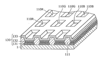
- FIG. 1 is a partially cutaway perspective view of an organic EL display device according to an embodiment.
- FIG. 2 is a perspective view illustrating an example of a pixel bank of the organic EL display device according to the embodiment.
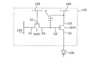
- FIG. 3 is an electric circuit diagram showing a configuration of a pixel circuit in the organic EL display device according to the embodiment.
- FIG. 4 is a schematic diagram showing a layout of one pixel in the TFT substrate according to the embodiment.
- FIG. 5 is a cross-sectional view of the TFT substrate according to the embodiment taken along line A-A ′ of FIG. 4.
- FIG. 6 is a schematic cross-sectional view of a TFT substrate according to the first modification.
- FIG. 7 is a schematic cross-sectional view of a TFT substrate according to the second modification.
- FIG. 1 is a partially cutaway perspective view of an organic EL display device according to an embodiment.
- FIG. 2 is a perspective view illustrating an example of a pixel bank of the organic EL display device according
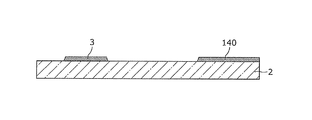
- FIG. 8A is a cross-sectional view of the gate electrode formation step in the TFT substrate manufacturing method according to the embodiment.
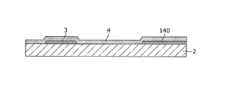
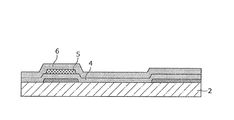
- FIG. 8B is a cross-sectional view of the first insulating layer (gate insulating film) forming step in the manufacturing method of the TFT substrate according to the embodiment.
- FIG. 8C is a cross-sectional view of the oxide semiconductor layer forming step in the manufacturing method of the TFT substrate according to the exemplary embodiment.
- FIG. 8D is a cross-sectional view of the second insulating layer forming step in the manufacturing method of the TFT substrate according to the embodiment.
- FIG. 8E is a cross-sectional view of the insulating layer contact hole forming step in the manufacturing method of the TFT substrate according to the exemplary embodiment.
- FIG. 8F is a cross-sectional view of the metal laminated film forming step in the manufacturing method of the TFT substrate according to the embodiment.
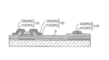
- FIG. 8G is a cross-sectional view of a metal laminated film patterning step (a step of forming a source electrode, a drain electrode, and a source wiring) in the TFT substrate manufacturing method according to the embodiment.
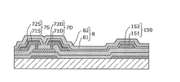
- FIG. 8H is a cross-sectional view of the third insulating layer forming step in the manufacturing method of the TFT substrate according to the embodiment.
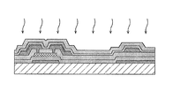
- FIG. 8I is a cross-sectional view of the heat treatment step in the manufacturing method of the TFT substrate according to the embodiment.
- FIG. 9A is a planar SEM (Scanning Electron Microscope) image showing that Cu abnormally grows from the Cu film of the source wiring at the intersection of the gate wiring and the source wiring.
- FIG. 9B is a cross-sectional SEM image taken along line B-B ′ of FIG. 9A.
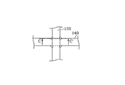
- FIG. 10A is a diagram schematically illustrating a state in which Cu abnormally grows from the Cu film of the source wiring at the intersection of the gate wiring and the source wiring.
- 10B is a cross-sectional view taken along line C-C ′ of FIG. 10A.
- FIG. 11 is a diagram showing experimental results of conditions for film formation and heat treatment of the insulating layer and whether or not Cu abnormal growth occurs.
- FIG. 11 is a diagram showing experimental results of conditions for film formation and heat treatment of the insulating layer and whether or not Cu abnormal growth occurs.
- FIG. 12 is a diagram schematically showing the film configuration of the source wiring and the insulating layer under each condition shown in FIG.
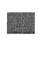
- FIG. 13 is a planar SEM image of the intersection of the gate wiring and the source wiring under the condition where abnormal Cu growth did not occur.
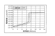
- FIG. 14A is a diagram showing the relationship between electric field strength and current density in a metal-oxide film-metal structure when the second silicon oxide film is formed at a deposition temperature of 230.degree.
- FIG. 14B is a diagram showing the relationship between the electric field strength and the current density in the metal-oxide film-metal structure when the second silicon oxide film is formed at a temperature of 290.degree.
- FIG. 1 is a partially cutaway perspective view of an organic EL display device according to an embodiment.
- FIG. 2 is a perspective view illustrating an example of a pixel bank of the organic EL display device according to the embodiment.
- an organic EL display device 100 includes a TFT substrate (TFT array substrate) 1 on which a plurality of thin film transistors are arranged, an anode 131 that is a lower electrode, and an EL layer 132 that is a light emitting layer made of an organic material. And a laminated structure with an organic EL element (light emitting part) 130 including a cathode 133 which is a transparent upper electrode.
- the organic EL display device 100 in this embodiment is a top emission type, and the anode 131 is a reflective electrode.
- the organic EL display device 100 is not limited to the top emission type, and may be a bottom emission type.
- the TFT substrate 1 has a plurality of pixels 110 arranged in a matrix, and each pixel 110 is provided with a pixel circuit 120.
- the organic EL element 130 is formed corresponding to each of the plurality of pixels 110, and the light emission of each organic EL element 130 is controlled by the pixel circuit 120 provided in each pixel 110.
- the organic EL element 130 is formed on an interlayer insulating film (planarization layer) formed so as to cover a plurality of thin film transistors.
- the organic EL element 130 has a configuration in which an EL layer 132 is disposed between the anode 131 and the cathode 133.
- a hole transport layer is further stacked between the anode 131 and the EL layer 132, and an electron transport layer is further stacked between the EL layer 132 and the cathode 133.
- another organic functional layer may be provided between the anode 131 and the cathode 133.
- Each pixel 110 is driven and controlled by the respective pixel circuit 120.
- Source wiring (signal wiring) 150 and a plurality of power supply wirings (not shown in FIG. 1) arranged in parallel with the source wiring 150 are formed.
- Each pixel 110 is partitioned by, for example, an orthogonal gate wiring 140 and a source wiring 150.
- the gate wiring 140 is connected to the gate electrode of the thin film transistor operating as a switching element included in each pixel circuit 120 for each row.
- the source wiring 150 is connected to the source electrode of the thin film transistor that operates as a switching element included in each pixel circuit 120 for each column.
- the power supply wiring is connected to the drain electrode of the thin film transistor operating as a driving element included in each pixel circuit 120 for each column.
- each pixel 110 of the organic EL display device 100 is configured by sub-pixels 110R, 110G, and 110B of three colors (red, green, and blue), and these sub-pixels 110R, 110G, and 110B. Are formed in a matrix on the display surface.
- the sub-pixels 110R, 110G, and 110B are separated from each other by the bank 111.
- the banks 111 are formed in a lattice shape so that the ridges extending in parallel to the gate wiring 140 and the ridges extending in parallel to the source wiring 150 intersect each other.
- Each of the portions surrounded by the protrusions (that is, the opening of the bank 111) and the sub-pixels 110R, 110G, and 110B have a one-to-one correspondence.
- the bank 111 is a pixel bank, but may be a line bank.
- the anode 131 is formed for each of the sub-pixels 110R, 110G, and 110B on the interlayer insulating film (flattening layer) on the TFT substrate 1 and in the opening of the bank 111.
- the EL layer 132 is formed for each of the sub-pixels 110R, 110G, and 110B on the anode 131 and in the opening of the bank 111.
- the transparent cathode 133 is continuously formed on the plurality of banks 111 so as to cover all the EL layers 132 (all the subpixels 110R, 110G, and 110B).
- the pixel circuit 120 is provided for each of the sub-pixels 110R, 110G, and 110B, and each of the sub-pixels 110R, 110G, and 110B and the corresponding pixel circuit 120 are electrically connected by a contact hole and a relay electrode.
- the sub-pixels 110R, 110G, and 110B have the same configuration except that the emission color of the EL layer 132 is different.
- FIG. 3 is an electric circuit diagram showing a configuration of a pixel circuit in the organic EL display device according to the embodiment.
- the pixel circuit 120 includes a thin film transistor SwTr that operates as a switching element, a thin film transistor DrTr that operates as a driving element, and a capacitor C that stores data to be displayed on the corresponding pixel 110.
- the thin film transistor SwTr is a switching transistor for selecting the pixel 110
- the thin film transistor DrTr is a drive transistor for driving the organic EL element 130.
- the thin film transistor SwTr includes a gate electrode G1 connected to the gate line 140, a source electrode S1 connected to the source line 150, a drain electrode D1 connected to the capacitor C and the gate electrode G2 of the thin film transistor DrTr, and a semiconductor film (FIG. Not shown).
- a predetermined voltage is applied to the connected gate wiring 140 and source wiring 150
- the voltage applied to the source wiring 150 is stored in the capacitor C as a data voltage.
- the thin film transistor DrTr includes a gate electrode G2 connected to the drain electrode D1 of the thin film transistor SwTr and the capacitor C, a drain electrode D2 connected to the power supply wiring 160 and the capacitor C, and a source electrode connected to the anode 131 of the organic EL element 130. It is comprised by S2 and a semiconductor film (not shown).
- the thin film transistor DrTr supplies a current corresponding to the data voltage held by the capacitor C from the power supply wiring 160 to the anode 131 of the organic EL element 130 through the source electrode S2. Thereby, in the organic EL element 130, a drive current flows from the anode 131 to the cathode 133, and the EL layer 132 emits light.
- the organic EL display device 100 having the above configuration employs an active matrix system in which display control is performed for each pixel 110 located at the intersection of the gate wiring 140 and the source wiring 150. Thereby, the corresponding organic EL element 130 selectively emits light by the thin film transistors SwTr and DrTr of each pixel 110 (each sub-pixel 110R, 110G, 110B), and a desired image is displayed.
- FIG. 4 is a schematic diagram showing a layout of one pixel in the TFT substrate according to the embodiment.
- FIG. 5 is a cross-sectional view of the TFT substrate taken along line AA ′ of FIG.
- the TFT substrate 1 in the organic EL display device 100 will be described.
- the pixels 110 are partitioned in a matrix by a plurality of orthogonal gate wirings 140 and a plurality of source wirings 150. As described above, each pixel 110 is provided with the thin film transistor SwTr, the thin film transistor DrTr, and the capacitor C.
- the TFT substrate 1 includes a substrate 2, a gate electrode 3, a gate insulating film 4, an oxide semiconductor layer 5, an insulating layer 6, a source electrode 7S and a drain electrode 7D, and an insulating layer. 8, a gate wiring 140, and a source wiring 150.
- the gate electrode 3, the source electrode 7S and the drain electrode 7D, the gate wiring 140, and the source wiring 150 are made of a metal material, and a layer in which these electrodes and wiring are formed is a metal layer (wiring layer). It is.
- the layer in which the gate electrode 3 and the gate wiring 140 are formed is a first wiring layer (first metal layer), and the layer in which the source electrode 7S and the drain electrode 7D and the source wiring 150 are formed is the first wiring layer.
- Two wiring layers (second metal layer).
- the power wiring 160 is also formed in the second wiring layer.
- Each wiring layer can be formed as a wiring or electrode separated into a predetermined shape by patterning a uniformly formed metal film (conductive film).
- the thin film transistor DrTr is composed of a gate electrode 3, a gate insulating film 4, an oxide semiconductor layer 5, a source electrode 7S, and a drain electrode 7D.
- the gate electrode 3, the source electrode 7S, and the drain electrode 7D correspond to the gate electrode G2, the source electrode S2, and the drain electrode D2 in FIG. 3, respectively.
- the thin film transistor Tr in this embodiment is a bottom-gate TFT, and is an oxide semiconductor TFT using an oxide semiconductor as a channel layer. Note that the thin film transistor SwTr can have the same structure as the thin film transistor DrTr.
- the substrate 2 is, for example, a glass substrate such as a G8 substrate. Further, as the substrate 2, a flexible substrate such as a resin substrate may be used. An undercoat layer may be formed on the surface of the substrate 2.
- the gate electrode 3 and the gate wiring 140 are formed in a predetermined shape above the substrate 2.
- a metal such as titanium (Ti), molybdenum (Mo), tungsten (W), aluminum (Al), gold (Au), copper (Cu), or ITO (Indium)
- a conductive oxide such as Tin Oxide (indium tin oxide) is used.
- an alloy such as molybdenum tungsten (MoW) can be used as the material of the gate electrode 3 and the gate wiring 140.
- the gate insulating film 4 is formed on the substrate 2 so as to cover the gate electrode 3 and the gate wiring 140.
- the gate insulating film 4 is formed between the gate electrode 3 and the oxide semiconductor layer 5 and is formed between the gate wiring 140 and the source wiring 150.
- an oxide thin film such as a silicon oxide film or a hafnium oxide film, a nitride film such as a silicon nitride film or a single layer film of a silicon oxynitride film, or a laminated film thereof is used.
- the oxide semiconductor layer 5 is formed in a predetermined shape above the substrate 2.
- the oxide semiconductor layer 5 is a channel layer (semiconductor layer) of the thin film transistor DrTr and is formed to face the gate electrode 3.
- the oxide semiconductor layer 5 is formed in an island shape on the gate insulating film 4 above the gate electrode 3.
- the oxide semiconductor layer 5 is preferably composed of a transparent amorphous oxide semiconductor (TAOS) such as InGaZnO x (IGZO) containing In—Ga—Zn—O.
- TAOS transparent amorphous oxide semiconductor
- IGZO InGaZnO x
- a thin film transistor using a transparent amorphous oxide semiconductor as a channel layer has high carrier mobility and is suitable for a large-screen and high-definition display device. Further, since the transparent amorphous oxide semiconductor can be formed at a low temperature, it can be easily formed over a flexible substrate.
- the amorphous oxide semiconductor of InGaZnO X can be formed by a vapor phase film forming method such as a sputtering method or a laser vapor deposition method using, for example, a polycrystalline sintered body having an InGaO 3 (ZnO) 4 composition.
- the insulating layer 6 is formed on the gate insulating film 4 so as to cover the oxide semiconductor layer 5. That is, the oxide semiconductor layer 5 is covered with the insulating layer 6, and the insulating layer 6 functions as a protective layer (channel protective layer) that protects the oxide semiconductor layer 5.
- the insulating layer 6 is also formed above the gate wiring 140.
- the insulating layer 6 is, for example, a single layer film of an oxide film such as a silicon oxide film (SiO 2 ) or an aluminum oxide film (Al 2 O 3 ), or a laminated film of these oxide films. A part of the insulating layer 6 is opened so as to penetrate, and the oxide semiconductor layer 5 is connected to the source electrode 7S and the drain electrode 7D through the opening (contact hole).
- an oxide film such as a silicon oxide film (SiO 2 ) or an aluminum oxide film (Al 2 O 3 )
- Al 2 O 3 aluminum oxide film
- the source electrode 7S and the drain electrode 7D are formed on the insulating layer 6 in a predetermined shape. Specifically, the source electrode 7S and the drain electrode 7D are connected to the oxide semiconductor layer 5 through contact holes provided in the insulating layer 6, and have a predetermined interval in the substrate horizontal direction on the insulating layer 6. They are arranged opposite each other.
- the source electrode 7S and the drain electrode 7D both contain copper (Cu) as a main component, and have a laminated structure of a copper film (Cu film) and a copper manganese alloy film (CuMn alloy film).
- the source electrode 7S is a laminated film of a Cu film 71S and a CuMn alloy film 72S formed on the Cu film 71S.
- the drain electrode 7D is a laminated film of a Cu film 71D and a CuMn alloy film 72D formed on the Cu film 71D.
- the source wiring 150 has the same configuration as the source electrode 7S and the drain electrode 7D. That is, the source wiring 150 is a Cu wiring made of a laminated film including the Cu film 151 and the CuMn alloy film (cap film) 152 on the Cu film 151.
- the source electrode 7S, the drain electrode 7D, and the source wiring 150 by using Cu, which is a low-resistance material, as the source electrode 7S, the drain electrode 7D, and the source wiring 150, the resistance of the source electrode 7S and the drain electrode 7D can be reduced, and the source electrode 7S and the drain electrode can be reduced.
- the source wiring 150 in the same layer as the electrode 7D can be a low resistance wiring.
- the film thickness of the Cu films 71S, 71D, and 151 is preferably larger than the film thickness of the CuMn alloy films 72S, 72D, and 152.
- the source electrode 7S, the drain electrode 7D, and the source wiring 150 by covering the Cu film with the cap film, it is possible to suppress the Cu film from being oxidized and the Cu film from being altered. Thereby, it can suppress that resistance of the source electrode 7S, the drain electrode 7D, and the source wiring 150 becomes high by oxidation of Cu.
- CuMn alloy films 72S, 72D, and 152 are used as the uppermost layer (cap film) of the source electrode 7S, the drain electrode 7D, and the source wiring 150.
- the CuMn alloy film means an alloy film of copper and manganese.
- the insulating layer 8 is a passivation layer and is formed on the insulating layer 6 so as to cover the source electrode 7S, the drain electrode 7D, and the source wiring 150.
- the insulating layer 8 is a laminated film of a plurality of silicon oxide films (SiO 2 ).
- the insulating layer 8 has a two-layer structure of a lower first silicon oxide film 81 and an upper second silicon oxide film 82. It is.
- the total film thickness of the first silicon oxide film 81 and the second silicon oxide film 82 is preferably 460 nm or more.
- the insulating layer 8 has a stacked structure of only a silicon oxide film, but has a stacked structure of a silicon oxide film and another oxide film such as an aluminum oxide film (Al 2 O 3 ). Also good.
- the insulating layer 8 may have a three-layer structure of a lower first silicon oxide film 81, an intermediate aluminum oxide film 83, and an upper second silicon oxide film 82, as shown in FIG. Good.
- the oxide semiconductor layer 5 is damaged by hydrogen or oxygen and deteriorates in electrical characteristics.
- the oxide semiconductor layer 5 is formed an aluminum oxide film above the oxide semiconductor layer 5, hydrogen or moisture generated in the upper layer is reduced. Since it can be blocked by the aluminum oxide film, diffusion of hydrogen and moisture into the oxide semiconductor layer 5 can be suppressed. Thereby, the oxide semiconductor layer 5 with stable electrical characteristics is obtained.
- the source electrode 7S, the drain electrode 7D, and the source wiring 150 have a two-layer structure of a Cu film and a CuMn alloy film, but the present invention is not limited to this.
- a three-layer structure of a Mo (molybdenum) film or a CuMn film, a Cu film, and a CuMn alloy film may be used.
- the source electrode 7S may be a laminated film of a base film 73S, a Cu film 71S, and a CuMn alloy film 72S, which is a Mo (molybdenum) film or a CuMn film.
- the drain electrode 7D is a laminated film of a base film 73D that is a Mo film or a CuMn film, a Cu film 71D, and a CuMn alloy film 72D
- the source wiring 150 is a base film 153 that is a Mo film or a CuMn film
- Cu A laminated film of the film 151 and the CuMn alloy film 152 may be used.
- the CuMn film or the Mo film as the lowermost layer of the source electrode 7S, the drain electrode 7D, and the source wiring 150, the Cu atoms in the Cu film are prevented from diffusing into the lower layer (the oxide semiconductor layer 5 or the like). In addition, the adhesion to the oxide semiconductor layer 5 can be improved.
- FIGS. 8A to 8I are cross-sectional views of each step in the method of manufacturing the thin film transistor substrate according to the embodiment.
- a substrate 2 is prepared, and a gate electrode 3 and a gate wiring 140 having a predetermined shape are formed above the substrate 2.
- a metal film is formed on the substrate 2 of a G8 glass substrate by a sputtering method, and the metal film is processed using a photolithography method and a wet etching method, thereby forming the gate electrode 3 and the gate wiring 140 having a predetermined shape. To do.
- a gate insulating film 4 (first insulating layer) is formed above the substrate 2.
- the gate insulating film 4 made of a silicon oxide film is formed on the entire surface of the substrate 2 by plasma CVD or the like so as to cover the gate electrode 3 and the gate wiring 140.
- an oxide semiconductor layer 5 having a predetermined shape is formed above the substrate 2.
- the oxide semiconductor layer 5 is formed over the gate insulating film 4.
- a transparent amorphous oxide semiconductor of InGaZnO X is formed on the gate insulating film 4 by a sputtering method or the like, and the transparent amorphous oxide semiconductor is processed by using a photolithography method and an etching method, so that the upper portion of the gate electrode 3 is formed. Then, an oxide semiconductor layer 5 having a predetermined shape is formed.
- an insulating layer 6 (second insulating layer) is formed on the gate insulating film 4 so as to cover the oxide semiconductor layer 5.
- the insulating layer 6 made of a silicon oxide film is formed on the entire surface of the substrate 2 by plasma CVD.
- contact holes CH1 and CH2 for contacting the oxide semiconductor layer 5 with the source electrode 7S and the drain electrode 7D are formed.
- the contact holes CH1 and CH2 are formed in the insulating layer 6 by using a photolithography method and an etching method so that a part of the oxide semiconductor layer 5 is exposed.
- a metal laminated film of a Cu film and a CuMn alloy film is formed. Specifically, a first metal film M1 made of a Cu film is formed on the insulating layer 6 so as to fill the contact holes CH1 and CH2 of the insulating layer 6, and then on the first metal film M1. A second metal film M2 made of a CuMn alloy film is formed by sputtering.
- the metal laminated film of the first metal film M1 (Cu film) and the second metal film M2 (CuMn alloy film) is processed into a predetermined shape by using a photolithography method and an etching method.
- the metal laminated film of the first metal film M1 and the second metal film M2 is patterned by wet etching containing hydrogen peroxide.
- the etching solution for example, a mixed aqueous solution of hydrogen peroxide and an organic acid can be used.
- a source electrode 7S having a laminated structure of a Cu film 71S and a CuMn alloy film 72S and a drain electrode 7D having a laminated structure of a Cu film 71D and a CuMn alloy film 72D are formed as shown in FIG. Can do.
- the source electrode 7S and the drain electrode 7D thus formed are formed on the insulating layer 6 so as to be connected to the oxide semiconductor layer 5.
- the source wiring 150 is formed as a copper wiring having a laminated structure of the Cu film 151 and the CuMn alloy film 152 by patterning at this time. Further, although not shown, the power supply wiring 160 is also formed at the same time.
- an insulating layer 8 (third insulating layer) is formed on the source wiring 150 which is a Cu wiring. Specifically, the insulating layer 8 is formed on the insulating layer 6 so as to cover the source electrode 7S, the drain electrode 7D, and the source wiring 150.
- the first silicon oxide film 81 (lower layer) is formed at a film formation temperature of 290 ° C. or less, and the second silicon oxide film 81 is formed above the first silicon oxide film 81 at a film formation temperature of 290 ° C. or less.
- the first silicon oxide film 81 is formed so as to cover the source electrode 7S, the drain electrode 7D, and the source wiring 150 by a plasma CVD method with the substrate temperature (deposition temperature) set to 290 ° C. or lower.
- the substrate temperature deposition temperature
- the Cu films 71S and 71D are not partially covered by the CuMn alloy films 72S and 72D.
- the substrate temperature is set to 290 ° C. or lower, and the second silicon oxide film 82 is formed on the first silicon oxide film 81 by plasma CVD.
- the first silicon oxide film 81 and the second silicon oxide film 82 are formed so that the total film thickness of the first silicon oxide film 81 and the second silicon oxide film 82 is 460 nm or more.
- the film formation temperature when forming the first silicon oxide film 81 is 230 ° C. or less. Further, it is more preferable that the film formation temperature when forming the second silicon oxide film 82 is higher than 230 ° C.
- the first silicon oxide film 81 is formed.
- the aluminum oxide film 83 may be formed by sputtering or the like, and then the second silicon oxide film 82 may be formed.
- heat treatment (annealing) is performed at a temperature exceeding 290 ° C.
- This heat treatment step is a treatment performed for stabilizing the characteristics of the oxide semiconductor layer 5, and for example, the heat treatment is performed at a set temperature of 300 ° C.
- oxygen vacancies in the oxide semiconductor layer 5 can be repaired, so that characteristics can be stabilized.
- low-resistance metal wiring is used for TFT substrate wiring (source wiring, gate wiring, power supply wiring) in order to realize high-speed driving.
- the source wiring and the power supply wiring are formed using the same material as the source electrode and the drain electrode in the TFT and in the same layer. For this reason, when selecting the material of the source electrode, the drain electrode, and the wiring of the same layer as these, it is necessary to consider not only the performance as a TFT but also the performance as a wiring. Therefore, it has been studied to use copper (Cu) having a low resistance as a material for the source electrode, the drain electrode, and the source wiring.
- Cu copper
- a silicon oxide film is used as an interlayer insulating film (insulating layer).
- an interlayer insulating film made of a silicon oxide film is formed so as to cover the source electrode, the drain electrode, and the source wiring.
- a technique for forming a cap film (protective layer) such as a CuMn alloy film between the Cu film and the silicon oxide film in the source electrode, the drain electrode, and the source wiring has been studied. That is, it is considered that the source electrode, the drain electrode, and the source wiring have a laminated structure of a Cu film and a cap film.
- abnormal growth of Cu from the Cu film is concentrated on the edge portion of the source wiring at the intersection with the gate wiring, as shown in FIGS. 9A, 9B, 10A, and 10B.
- FIG. 9A and 9B are SEM images showing abnormal growth of Cu from the Cu film 151 of the source wiring 150 at a portion where the gate wiring 140 and the source wiring 150 intersect, and FIG. 9A is a planar SEM image. 9B is a cross-sectional SEM image taken along the line BB ′ of FIG. 9A.
- FIGS. 10A and 10B are diagrams schematically showing a state in which Cu abnormally grows from the Cu film 151 of the source wiring 150 at a portion where the gate wiring 140 and the source wiring 150 intersect, and FIG. 10A is a plan view.
- FIG. 10B is a cross-sectional view taken along the line CC ′ of FIG. 10A.
- the inventors of the present invention diligently investigated the cause of abnormal Cu growth, and found that abnormal Cu growth occurred due to the following reasons.
- the present inventor has found that the cause of abnormal growth of Cu from the Cu film depends on the film formation conditions of the insulating layer 8 formed above the Cu film and the annealing conditions after the film formation of the insulating layer 8. I found it.
- FIG. 11 the inventor of the present application is concerned with whether or not Cu grows abnormally from the Cu film 151 of the source wiring 150 covered with the insulating layer 8 under 10 conditions 1 to 10.
- the experiment was conducted.
- the conditions of the insulating layer 8 (lower layer, intermediate layer, upper layer) indicate the film thickness and the film forming temperature.
- FIG. 12 schematically shows the film configuration of the source wiring 150 and the insulating layer 8 under the conditions shown in FIG.
- FIG. 13 is a planar SEM image of a crossing portion between the gate wiring 140 and the source wiring 150 under the condition where abnormal Cu growth did not occur.
- FIG. 13 is compared with FIG. 10A described above, in FIG. 13, it can be seen that abnormal growth of Cu does not occur at the edge portion of the source wiring at the intersection with the gate wiring.
- first SiO film first silicon oxide film
- second SiO film the deposition temperature of the upper second silicon oxide film (second SiO film) and the annealing temperature should be lower.
- the total thickness of the insulating layer should be greater than a certain value. By keeping the total film thickness of the insulating layer above a certain value, abnormal growth of Cu occurs even when the deposition temperature of the second silicon oxide film (second SiO film) is high or annealing is performed. I understand that I don't.
- AlO film aluminum oxide film
- the film formation temperature of the first silicon oxide film (first SiO film) and the second silicon oxide film (second SiO film) and the total film of the first silicon oxide film and the second silicon oxide film It has been found that abnormal growth of Cu may or may not occur depending on the thickness. If the total film thickness of the insulating layer 8 is smaller than a predetermined film thickness, abnormal growth of Cu occurs when the film forming temperature when forming the upper layer of the insulating layer 8 is high or by subsequent annealing at 300 ° C. I found out that
- the present disclosure has been made on the basis of such knowledge, and the inventor of the present application forms an insulating layer 8 on a Cu wiring (source wiring 150 and the like) by forming the insulating layer 8 under predetermined film forming conditions. It has been found that even when heat treatment is performed after the layer 8 is formed, abnormal growth of Cu from the Cu wiring can be suppressed.
- the film formation temperature of the first silicon oxide film 81 and the second silicon oxide film 82 is set to a certain temperature or less, and the first silicon oxide film 81 and the second silicon oxide film 82 are formed. It was found that the abnormal growth of Cu from the Cu wiring can be suppressed by setting the total film thickness with the silicon oxide film 82 to a certain film thickness or more.
- the upper limit temperature of the deposition temperature of the first silicon oxide film 81 needs to be about 290 ° C. This is because Cu abnormal growth occurs when the film is formed at 360 ° C. under the condition 7 shown in FIG. 11, whereas Cu abnormal growth is suppressed even after annealing when the film is formed at 290 ° C. under the condition 8. Because it is done.
- the upper limit temperature of the second silicon oxide film 82 needs to be about 290 ° C.
- the upper limit temperature of the film formation temperature of the first silicon oxide film 81 and the second silicon oxide film 82 is preferably 290 ° C. or less.
- the first silicon oxide film 81 is formed at a film forming temperature of 290 ° C. or lower, and then A second silicon oxide film 82 is formed above the first silicon oxide film 81 at a deposition temperature of 290 ° C. or less, and the total of the first silicon oxide film 81 and the second silicon oxide film 82
- the film thickness is set to 460 nm or more.
- the film formation temperature of the first silicon oxide film 81 formed immediately above the CuMn alloy film (cap film) is 230 ° C. or lower.
- the deposition temperature of the first silicon oxide film 81 immediately above the CuMn alloy film exceeds 230 ° C.
- the surface of the CuMn alloy film is altered. Specifically, when the deposition temperature of the first silicon oxide film 81 is 230 ° C., the surface of the CuMn alloy film is not altered, but the deposition temperature of the first silicon oxide film 81 is 245 ° C. In this case, the surface of the CuMn alloy film was altered.
- the film formation temperature of the first silicon oxide film 81 be 230 ° C. or lower.
- the upper limit temperature of the first silicon oxide film 81 is preferably set to 230 ° C. or less.
- the film formation temperature of the second silicon oxide film 82 may be a temperature that can ensure a withstand voltage. This point will be described with reference to FIGS. 14A and 14B.
- FIG. 14A is a diagram showing the relationship between the electric field strength and the current density in the metal-oxide film-metal structure when the second silicon oxide film 82 is formed at a deposition temperature of 230.degree.
- FIG. 14B is a diagram showing the relationship between the electric field strength and the current density in the metal-oxide film-metal structure when the second silicon oxide film 82 is formed at a deposition temperature of 290.degree.
- FIG. 14A shows the experimental results of three samples.
- the withstand voltage is insufficient when the second silicon oxide film 82 is formed at a deposition temperature of 230.degree. In this case, a desired thin film transistor cannot be obtained.
- the film formation temperature of the second silicon oxide film 82 is at least 290 ° C.
- the withstand voltage can be secured.
- the lower limit temperature of the second silicon oxide film 82 may be at least a temperature higher than 230 ° C.
- the film formation temperature of the first silicon oxide film 81 is 230 ° C.
- the film formation temperature of the second silicon oxide film 82 is preferably greater than 230 ° C. and 290 ° C. or less.
- the thin film transistor substrate As described above, the thin film transistor substrate, the method for manufacturing the thin film transistor substrate, and the organic EL display device have been described based on the embodiments. However, the present invention is not limited to the above embodiments.
- the thin film transistor is a bottom gate type, but may be a top gate type.
- the thin film transistor is a channel etching stopper type (channel protection type), but may be a channel etching type. That is, in the above embodiment, the insulating layer 6 may not be formed.
- an organic EL display device is described as a display device using a thin film transistor substrate.
- the thin film transistor substrate in the above embodiment is used for other display devices using an active matrix substrate such as a liquid crystal display device. Can also be applied.
- the display device such as the organic EL display device described above can be used as a flat panel display and applied to all electronic devices having a display panel such as a television set, a personal computer, and a mobile phone. can do. In particular, it is suitable for a large-screen and high-definition display device.
- the technology disclosed herein can be widely used in a thin film transistor substrate using an oxide semiconductor, a manufacturing method thereof, a display device such as an organic EL display device using the thin film transistor substrate, and the like.
Landscapes
- Engineering & Computer Science (AREA)
- Microelectronics & Electronic Packaging (AREA)
- Manufacturing & Machinery (AREA)
- Thin Film Transistor (AREA)
- Electroluminescent Light Sources (AREA)
- Electrodes Of Semiconductors (AREA)
Abstract
Description
まず、TFT基板が用いられる表示装置の一例として、有機EL表示装置の構成について説明する。
図1は、実施の形態に係る有機EL表示装置の一部切り欠き斜視図である。図2は、実施の形態に係る有機EL表示装置のピクセルバンクの例を示す斜視図である。
次に、実施の形態に係るTFT基板の構成について、図4及び図5を用いて説明する。図4は、実施の形態に係るTFT基板における一画素のレイアウトを示す模式図である。図5は、図4のA-A’線におけるTFT基板の断面図である。
次に、実施の形態に係るTFT基板1の製造方法について、図8A~図8Iを用いて説明する。図8A~図8Iは、実施の形態に係る薄膜トランジスタ基板の製造方法における各工程の断面図である。
ここで、本開示に至った経緯を含めて、本開示の特徴となる絶縁層8の成膜条件について詳細に説明する。
以上、薄膜トランジスタ基板、薄膜トランジスタ基板の製造方法及び有機EL表示装置について、実施の形態に基づいて説明したが、本発明は、上記実施の形態に限定されるものではない。
2 基板
3、G1、G2 ゲート電極
4 ゲート絶縁膜
5 酸化物半導体層
6、8 絶縁層
7S、S1、S2 ソース電極
7D、D1、D2 ドレイン電極
71S、71D、151 Cu膜
72S、72D、152 CuMn合金膜
73S、73D、153 下地膜
81 第1のシリコン酸化膜
82 第2のシリコン酸化膜
83 酸化アルミニウム膜
100 有機EL表示装置
110 画素
110R、110G、110B サブ画素
111 バンク
120 画素回路
130 有機EL素子
131 陽極
132 EL層
133 陰極
140 ゲート配線
150 ソース配線
160 電源配線
SwTr、DrTr 薄膜トランジスタ
C キャパシタ
CH1、CH2 コンタクトホール
Claims (4)
- 酸化物半導体層を有する薄膜トランジスタを備える薄膜トランジスタ基板の製造方法であって、
基板の上方に、銅膜及び当該銅膜上のキャップ膜を含む積層膜からなる銅配線を形成する工程と、
前記銅配線の上に絶縁層を成膜する工程と、
前記絶縁層を成膜した後に、290℃を越える温度で熱処理をする工程とを含み、
前記絶縁層を成膜する工程は、
290℃以下の成膜温度で第1のシリコン酸化膜を成膜する工程と、
290℃以下の成膜温度で前記第1のシリコン酸化膜の上方に第2のシリコン酸化膜を成膜する工程とを含み、
前記第1のシリコン酸化膜と前記第2のシリコン酸化膜との合計膜厚は、460nm以上である
薄膜トランジスタ基板の製造方法。 - 前記第1のシリコン酸化膜の成膜温度は230℃以下であり、
前記第2のシリコン酸化膜の成膜温度は230℃よりも大きい
請求項1に記載の薄膜トランジスタ基板の製造方法。 - 前記第1のシリコン酸化膜を成膜する工程では、
前記第1のシリコン酸化膜を成膜した結果、前記銅膜の一部が、前記キャップ膜に被覆されることなく、前記第1のシリコン酸化膜の少なくとも一部に接触する
請求項1又は2に記載の薄膜トランジスタ基板の製造方法。 - 前記キャップ層は、CuMn合金膜である
請求項1~3のいずれか1項に記載の薄膜トランジスタ基板の製造方法。
Priority Applications (2)
| Application Number | Priority Date | Filing Date | Title |
|---|---|---|---|
| US15/314,942 US20170207326A1 (en) | 2014-06-03 | 2015-06-02 | Method of manufacturing thin-film transistor substrate |
| JP2016525702A JP6311900B2 (ja) | 2014-06-03 | 2015-06-02 | 薄膜トランジスタ基板の製造方法 |
Applications Claiming Priority (2)
| Application Number | Priority Date | Filing Date | Title |
|---|---|---|---|
| JP2014-115264 | 2014-06-03 | ||
| JP2014115264 | 2014-06-03 |
Publications (1)
| Publication Number | Publication Date |
|---|---|
| WO2015186349A1 true WO2015186349A1 (ja) | 2015-12-10 |
Family
ID=54766432
Family Applications (1)
| Application Number | Title | Priority Date | Filing Date |
|---|---|---|---|
| PCT/JP2015/002777 Ceased WO2015186349A1 (ja) | 2014-06-03 | 2015-06-02 | 薄膜トランジスタ基板の製造方法 |
Country Status (3)
| Country | Link |
|---|---|
| US (1) | US20170207326A1 (ja) |
| JP (1) | JP6311900B2 (ja) |
| WO (1) | WO2015186349A1 (ja) |
Families Citing this family (2)
| Publication number | Priority date | Publication date | Assignee | Title |
|---|---|---|---|---|
| KR102556021B1 (ko) * | 2017-10-13 | 2023-07-17 | 삼성디스플레이 주식회사 | 디스플레이 장치 및 그 제조방법 |
| CN113496869A (zh) * | 2020-04-03 | 2021-10-12 | 重庆超硅半导体有限公司 | 一种外延基底用硅晶片之背面膜层及制造方法 |
Citations (3)
| Publication number | Priority date | Publication date | Assignee | Title |
|---|---|---|---|---|
| JP2011091364A (ja) * | 2009-07-27 | 2011-05-06 | Kobe Steel Ltd | 配線構造およびその製造方法、並びに配線構造を備えた表示装置 |
| JP2012243779A (ja) * | 2011-05-13 | 2012-12-10 | Kobe Steel Ltd | Cu合金膜および表示装置 |
| JP2013033927A (ja) * | 2011-08-02 | 2013-02-14 | Samsung Electronics Co Ltd | 薄膜トランジスタ表示板及びその製造方法 |
Family Cites Families (2)
| Publication number | Priority date | Publication date | Assignee | Title |
|---|---|---|---|---|
| JP2001168098A (ja) * | 1999-12-10 | 2001-06-22 | Seiko Epson Corp | 半導体装置及びパターンデータ作成方法 |
| KR101913207B1 (ko) * | 2011-10-12 | 2018-11-01 | 삼성디스플레이 주식회사 | 박막 트랜지스터, 및 박막 트랜지스터 표시판과 이들을 제조하는 방법 |
-
2015
- 2015-06-02 JP JP2016525702A patent/JP6311900B2/ja active Active
- 2015-06-02 US US15/314,942 patent/US20170207326A1/en not_active Abandoned
- 2015-06-02 WO PCT/JP2015/002777 patent/WO2015186349A1/ja not_active Ceased
Patent Citations (3)
| Publication number | Priority date | Publication date | Assignee | Title |
|---|---|---|---|---|
| JP2011091364A (ja) * | 2009-07-27 | 2011-05-06 | Kobe Steel Ltd | 配線構造およびその製造方法、並びに配線構造を備えた表示装置 |
| JP2012243779A (ja) * | 2011-05-13 | 2012-12-10 | Kobe Steel Ltd | Cu合金膜および表示装置 |
| JP2013033927A (ja) * | 2011-08-02 | 2013-02-14 | Samsung Electronics Co Ltd | 薄膜トランジスタ表示板及びその製造方法 |
Also Published As
| Publication number | Publication date |
|---|---|
| JPWO2015186349A1 (ja) | 2017-04-20 |
| JP6311900B2 (ja) | 2018-04-18 |
| US20170207326A1 (en) | 2017-07-20 |
Similar Documents
| Publication | Publication Date | Title |
|---|---|---|
| US20160204126A1 (en) | Thin-film transistor substrate and method for fabricating the same | |
| USRE48032E1 (en) | Thin-film semiconductor substrate, light-emitting panel, and method of manufacturing the thin-film semiconductor substrate | |
| JP6019507B2 (ja) | 薄膜トランジスタ基板及び薄膜トランジスタ基板の製造方法 | |
| US10276722B2 (en) | Thin film transistor | |
| US10204973B2 (en) | Display device and thin-film transistors substrate | |
| JP5609989B2 (ja) | 表示装置、及び表示装置の製造方法 | |
| US8994020B2 (en) | Thin film transistor with channel protection film of specific resistivity | |
| US10249761B2 (en) | Thin-film transistor substrate | |
| JP2015149467A (ja) | 薄膜トランジスタ基板の製造方法 | |
| US9627515B2 (en) | Method of manufacturing thin-film transistor substrate | |
| US9595601B2 (en) | Method of fabricating thin-film semiconductor substrate | |
| JP6311900B2 (ja) | 薄膜トランジスタ基板の製造方法 | |
| WO2013187046A1 (ja) | 薄膜トランジスタ | |
| JP6500202B2 (ja) | 薄膜トランジスタ及び薄膜トランジスタの製造方法 | |
| WO2013108301A1 (ja) | 薄膜トランジスタ | |
| JP6500203B2 (ja) | 薄膜トランジスタ及び薄膜トランジスタの製造方法 | |
| JP6388282B2 (ja) | 薄膜トランジスタ基板の製造方法 | |
| JP6248265B2 (ja) | 薄膜トランジスタ基板の製造方法 | |
| WO2016067585A1 (ja) | 薄膜半導体装置、有機el表示装置及び薄膜半導体装置の製造方法 | |
| WO2013108300A1 (ja) | 薄膜トランジスタ | |
| JP2012028473A (ja) | 薄膜トランジスタ及びこれを用いた表示装置、並びに、薄膜トランジスタの製造方法 |
Legal Events
| Date | Code | Title | Description |
|---|---|---|---|
| 121 | Ep: the epo has been informed by wipo that ep was designated in this application |
Ref document number: 15803137 Country of ref document: EP Kind code of ref document: A1 |
|
| WWE | Wipo information: entry into national phase |
Ref document number: 15314942 Country of ref document: US |
|
| ENP | Entry into the national phase |
Ref document number: 2016525702 Country of ref document: JP Kind code of ref document: A |
|
| NENP | Non-entry into the national phase |
Ref country code: DE |
|
| 122 | Ep: pct application non-entry in european phase |
Ref document number: 15803137 Country of ref document: EP Kind code of ref document: A1 |