WO2015182608A1 - 振動検出システム、信号処理装置及び信号処理方法 - Google Patents
振動検出システム、信号処理装置及び信号処理方法 Download PDFInfo
- Publication number
- WO2015182608A1 WO2015182608A1 PCT/JP2015/065110 JP2015065110W WO2015182608A1 WO 2015182608 A1 WO2015182608 A1 WO 2015182608A1 JP 2015065110 W JP2015065110 W JP 2015065110W WO 2015182608 A1 WO2015182608 A1 WO 2015182608A1
- Authority
- WO
- WIPO (PCT)
- Prior art keywords
- vibration
- signal
- period
- wave
- receiving device
- Prior art date
- Legal status (The legal status is an assumption and is not a legal conclusion. Google has not performed a legal analysis and makes no representation as to the accuracy of the status listed.)
- Ceased
Links
Images


Classifications
-
- G—PHYSICS
- G01—MEASURING; TESTING
- G01V—GEOPHYSICS; GRAVITATIONAL MEASUREMENTS; DETECTING MASSES OR OBJECTS; TAGS
- G01V1/00—Seismology; Seismic or acoustic prospecting or detecting
- G01V1/003—Seismic data acquisition in general, e.g. survey design
-
- G—PHYSICS
- G01—MEASURING; TESTING
- G01V—GEOPHYSICS; GRAVITATIONAL MEASUREMENTS; DETECTING MASSES OR OBJECTS; TAGS
- G01V1/00—Seismology; Seismic or acoustic prospecting or detecting
- G01V1/001—Acoustic presence detection
-
- G—PHYSICS
- G01—MEASURING; TESTING
- G01V—GEOPHYSICS; GRAVITATIONAL MEASUREMENTS; DETECTING MASSES OR OBJECTS; TAGS
- G01V1/00—Seismology; Seismic or acoustic prospecting or detecting
- G01V1/16—Receiving elements for seismic signals; Arrangements or adaptations of receiving elements
- G01V1/162—Details
- G01V1/164—Circuits therefore
-
- G—PHYSICS
- G01—MEASURING; TESTING
- G01V—GEOPHYSICS; GRAVITATIONAL MEASUREMENTS; DETECTING MASSES OR OBJECTS; TAGS
- G01V1/00—Seismology; Seismic or acoustic prospecting or detecting
- G01V1/28—Processing seismic data, e.g. for interpretation or for event detection
- G01V1/284—Application of the shear wave component and/or several components of the seismic signal
-
- G—PHYSICS
- G01—MEASURING; TESTING
- G01V—GEOPHYSICS; GRAVITATIONAL MEASUREMENTS; DETECTING MASSES OR OBJECTS; TAGS
- G01V1/00—Seismology; Seismic or acoustic prospecting or detecting
- G01V1/28—Processing seismic data, e.g. for interpretation or for event detection
- G01V1/288—Event detection in seismic signals, e.g. microseismics
-
- G—PHYSICS
- G01—MEASURING; TESTING
- G01V—GEOPHYSICS; GRAVITATIONAL MEASUREMENTS; DETECTING MASSES OR OBJECTS; TAGS
- G01V1/00—Seismology; Seismic or acoustic prospecting or detecting
- G01V1/28—Processing seismic data, e.g. for interpretation or for event detection
- G01V1/36—Effecting static or dynamic corrections on records, e.g. correcting spread; Correlating seismic signals; Eliminating effects of unwanted energy
- G01V1/364—Seismic filtering
-
- G—PHYSICS
- G01—MEASURING; TESTING
- G01V—GEOPHYSICS; GRAVITATIONAL MEASUREMENTS; DETECTING MASSES OR OBJECTS; TAGS
- G01V1/00—Seismology; Seismic or acoustic prospecting or detecting
- G01V1/28—Processing seismic data, e.g. for interpretation or for event detection
- G01V1/36—Effecting static or dynamic corrections on records, e.g. correcting spread; Correlating seismic signals; Eliminating effects of unwanted energy
- G01V1/37—Effecting static or dynamic corrections on records, e.g. correcting spread; Correlating seismic signals; Eliminating effects of unwanted energy specially adapted for seismic systems using continuous agitation of the ground, e.g. using pulse compression of frequency swept signals for enhancement of received signals
-
- G—PHYSICS
- G01—MEASURING; TESTING
- G01V—GEOPHYSICS; GRAVITATIONAL MEASUREMENTS; DETECTING MASSES OR OBJECTS; TAGS
- G01V1/00—Seismology; Seismic or acoustic prospecting or detecting
- G01V1/02—Generating seismic energy
- G01V1/143—Generating seismic energy using mechanical driving means, e.g. motor driven shaft
- G01V1/153—Generating seismic energy using mechanical driving means, e.g. motor driven shaft using rotary unbalanced masses
-
- G—PHYSICS
- G01—MEASURING; TESTING
- G01V—GEOPHYSICS; GRAVITATIONAL MEASUREMENTS; DETECTING MASSES OR OBJECTS; TAGS
- G01V2210/00—Details of seismic processing or analysis
- G01V2210/10—Aspects of acoustic signal generation or detection
- G01V2210/12—Signal generation
- G01V2210/123—Passive source, e.g. microseismics
- G01V2210/1232—Earthquakes
-
- G—PHYSICS
- G01—MEASURING; TESTING
- G01V—GEOPHYSICS; GRAVITATIONAL MEASUREMENTS; DETECTING MASSES OR OBJECTS; TAGS
- G01V2210/00—Details of seismic processing or analysis
- G01V2210/20—Trace signal pre-filtering to select, remove or transform specific events or signal components, i.e. trace-in/trace-out
- G01V2210/21—Frequency-domain filtering, e.g. band pass
-
- G—PHYSICS
- G01—MEASURING; TESTING
- G01V—GEOPHYSICS; GRAVITATIONAL MEASUREMENTS; DETECTING MASSES OR OBJECTS; TAGS
- G01V2210/00—Details of seismic processing or analysis
- G01V2210/30—Noise handling
- G01V2210/34—Noise estimation
-
- G—PHYSICS
- G01—MEASURING; TESTING
- G01V—GEOPHYSICS; GRAVITATIONAL MEASUREMENTS; DETECTING MASSES OR OBJECTS; TAGS
- G01V2210/00—Details of seismic processing or analysis
- G01V2210/60—Analysis
- G01V2210/64—Geostructures, e.g. in 3D data cubes
- G01V2210/646—Fractures
Definitions
- the present invention relates to a vibration detection system, a signal processing device, and a signal processing method for detecting an underground vibration by removing an influence of a vibration wave generated from a hypocenter device.
- ACROSS Accelerated Routinely Operated Signal System
- ACROSS can generate a precisely controlled signal (vibration wave) by rotating a cylindrical eccentric weight, and is suitable for underground observation.
- Patent Document 1 discloses a method of observing the inside of a basement by recording the energy of a reflected wave generated by reflecting a signal generated by a hypocenter device at a dike layer.
- Shale gas is collected using a so-called hydraulic crushing method in which a pipe is horizontally inserted into a shale layer containing shale gas and high-pressure water is injected from the pipe to artificially create a fracture.
- the seismic source device used in the active seismic exploration described above is operated in the vicinity of the point where hydraulic fracturing is being performed, the vibration wave generated from this seismic source device will become micro seismic noise associated with hydraulic fracturing. It is not possible to make accurate micro seismic observations. For this reason, the operation of the seismic source device is usually stopped during micro seismic observation, and active seismic exploration is carried out at times other than micro seismic observation.
- the present invention has been made in view of such problems, and an object of the present invention is to provide a vibration detection system, a signal processing apparatus, and a signal processing method capable of removing the influence of vibration waves generated from a seismic source apparatus.
- a seismic source device that generates a vibration wave repeated at a predetermined cycle, a vibration receiving device that receives a response wave based on the vibration wave transmitted through the ground, and the vibration receiving device include A vibration detection system comprising: a signal processing device that processes a vibration signal according to a received response wave.
- the signal processing device has a storage unit that stores the vibration signal received by the receiving device, and a period according to the periodicity of the vibration wave generated by the source device from the stored vibration signal.
- a separation unit that separates the individual periodic signal, a calculation unit that calculates a standard periodic signal from the separated individual periodic signal, and a differential signal that indicates a difference between the vibration signal received by the vibration receiving device and the standard periodic signal.
- the seismic source device may change the frequency of the generated vibration wave within the period.
- the calculation unit may calculate the standard periodic signal by averaging the plurality of individual periodic signals by using the inverse of the variance of noise included in each of the plurality of individual periodic signals as a weight. Good.
- the calculation unit may calculate a median value of a plurality of the individual periodic signals as the standard periodic signal.
- the accumulation unit accumulates the standard periodic signal calculated by the calculation unit in association with an environmental condition, and the generation unit corresponds to an environmental condition when the vibration receiving device receives the vibration signal.
- the difference signal may be generated based on the standard periodic signal.
- the seismic device is a seismic device that generates a vibration wave including a horizontal vibration and a vertical vibration, and generates a first vibration wave having a first polarity vibration signal in a first period, A second vibration wave having a second polarity vibration signal obtained by inverting the first polarity in the horizontal direction or the vertical direction in a second period having the same length as the first period may be generated.
- the seismic source device generates a transition vibration wave in an inversion period between the first period and the second period, and the calculation unit receives the transition received by the vibration receiving apparatus in the inversion period of a plurality of times.
- the median value of the vibration signal based on the vibration wave may be calculated as the standard periodic signal in the inversion period.
- the seismic source device generates a transitional vibration wave in an inversion period between the first period and the second period, and the calculation unit calculates the ground of the ground calculated in the first period or the second period.
- the standard periodic signal may be calculated based on a transfer function and the transition vibration wave.
- a signal processing device for removing a signal based on a vibration wave generated by a hypocenter device from a vibration signal received by a vibration receiving device.
- the signal processing device separates an accumulation unit that accumulates the vibration signal received by the vibration receiving device, and an individual periodic signal having a period according to the periodicity of the vibration wave generated by the source device from the accumulated vibration signal.
- a signal processing method for removing a signal based on a vibration wave generated by a hypocenter device from a vibration signal received by a vibration receiving device.
- the vibration signal received by the vibration receiving device is accumulated, and the individual periodic signal having a period corresponding to the periodicity of the vibration wave generated by the seismic source device is separated from the accumulated vibration signal.
- the influence of the vibration wave generated from the seismic source device can be removed.
- FIG. 1 It is a figure which shows the system configuration
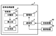
- FIG. 1 is a diagram schematically showing a system configuration of the vibration detection system S.
- the vibration detection system S includes a signal processing device 1, a hypocenter device 50, and a plurality of vibration receiving devices 60.
- the signal processing device 1, the hypocenter device 50, and the vibration receiving device 60 are synchronized by the GPS system 100.
- the hypocenter device 50 artificially generates a controlled steady vibration wave and radiates it toward the basement.
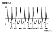
- the outline of the vibration wave generated by the source apparatus 50 is shown in FIG.
- the seismic source device 50 generates a vibration wave that is repeated at a predetermined cycle (for example, 200 seconds).
- the vibration wave generated from the seismic source device 50 has a sweep waveform whose frequency changes within a predetermined period.
- the seismic source device 50 of the present embodiment generates a vibration wave whose frequency changes between 5 Hz and 50 Hz within a period of 200 seconds.
- the plurality of vibration receiving devices 60 are triaxial (XYZ) seismometers installed at different points. Each vibration receiving device 60 receives a vibration signal based on a vibration wave (response wave) generated from the earthquake source device 50 and transmitted through the ground, and measures the underground vibration at the installation point.
- a vibration wave response wave
- the vibration receiving device 60 performs hydraulic fracturing in addition to the vibration signal based on the vibration wave generated by the source device 50.
- the vibration signal based on the micro seismic accompanying the vibration and the vibration signal based on the natural earthquake are also received.
- the vibration signal received by the vibration receiving device 60 is referred to as a measurement vibration signal.
- the measurement vibration signal includes vibration signals based on micro seismic and natural earthquakes in addition to vibration signals based on vibration waves generated from the seismic source device 50.
- the micro seismic and natural vibrations in the measurement vibration signal are included.
- the vibration signal based on the earthquake is hereinafter referred to as a differential signal.
- the signal processing device 1 is communicably connected to each of the plurality of vibration receiving devices 60, and acquires and analyzes the measurement vibration signal received by the vibration receiving device 60. Specifically, the signal processing device 1 removes the influence based on the vibration wave of the hypocenter device 50 from the measured vibration signal, and extracts the difference signal. In addition, the signal processing apparatus 1 is good also as connecting with the epicenter apparatus 50 so that communication is possible, and acquiring various information from the epicenter apparatus 50 as needed. Hereinafter, a specific configuration for the signal processing device 1 to extract the differential signal will be described.
- FIG. 3 is a block diagram showing a functional configuration of the signal processing apparatus 1. As shown in FIG. 3, the signal processing device 1 includes a communication unit 2, a storage unit 3, and a control unit 4.
- the communication unit 2 transmits and receives various types of information to and from the seismic source device 50 and the vibration receiving device 60 via a predetermined wired or wireless communication line.
- the communication unit 2 receives a measurement vibration signal measured by each vibration receiving device 60 from each of the vibration receiving devices 60.
- the measurement vibration signal received from the vibration receiving device 60 is supplied to the control unit 4, and the control unit 4 removes the influence based on the vibration wave of the source device 50 and extracts a difference signal.
- the communication unit 2 receives log information of the operation of the epicenter device 50 from the seismic device 50. By analyzing the log information, the signal processing device 1 can calculate the vibration wave generated from the seismic source device 50. As shown in FIG.
- the seismic source device 50 is precisely controlled during steady operation, so that the generated vibration wave is also controlled in advance.
- the control of the epicenter device 50 is not stable during the inversion period described later, the generated vibration wave is not stable. Even in such a period when the control is not stable, the signal processing apparatus 1 can calculate the vibration wave using the log information.
- the storage unit 3 is composed of, for example, a ROM and a RAM.
- the storage unit 3 stores various programs and various data for causing the signal processing apparatus 1 to function.
- the accumulation unit 3 accumulates various types of information received from the epicenter device 50 and the vibration receiving device 60 via the communication unit 2. Specifically, the accumulation unit 3 accumulates the measurement vibration signal received by the vibration receiving device 60, the log information received from the earthquake source device 50, and the like.
- the transfer function of the ground may vary depending on the environmental conditions such as weather and temperature.
- the vibration wave generated from the source device 50 is received as a different vibration signal in the vibration receiving device 60. May be.
- the transfer function of the frozen ground in the winter differs from the transfer function of the muddy ground in the summer.
- the received vibration signal received by the device 60 is also different.
- the storage unit 3 may store the measurement vibration signal (specifically, a standard periodic signal described later) received by the vibration receiving device 60 in association with the environmental condition.
- the control unit 4 is constituted by a CPU, for example.
- the control unit 4 comprehensively controls functions related to the signal processing device 1 by executing various programs stored in the storage unit 3. Specifically, the control unit 4 extracts, from the measured vibration signal received by the vibration receiving device 60, a differential signal from which the influence based on the vibration wave of the seismic source device 50 is removed.
- the vibration wave generated from the hypocenter device 50 is precisely controlled and has a sweep waveform having periodicity (see FIG. 2). Therefore, in a situation where no other vibration such as a natural earthquake occurs, the vibration receiving device 60 periodically receives a substantially constant measurement vibration signal.
- a substantially constant measurement vibration signal is calculated as a standard periodic signal.
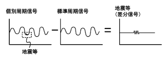
- the vibration receiving device 60 receives a measurement vibration signal based on the vibration wave generated from the source device 50 and the vibration wave accompanying the natural earthquake or the like. Therefore, the control unit 4 subtracts the standard periodic signal from the measured vibration signal received by the vibration receiving device 60, thereby removing the influence of the vibration receiving device 60 and extracting only the difference signal based on the vibration wave accompanying a natural earthquake or the like. To do. More specifically, the measurement vibration signal is separated into individual periodic signals having the same length as the standard periodic signal, and the difference signal is extracted by subtracting the standard periodic signal from the individual periodic signal.
- the control unit 4 will be described.
- a seismic device that artificially generates vibration waves there are a seismic device that generates only one of the vertical and horizontal vibration waves, and a seismic device that generates both vertical and horizontal vibration waves.
- a hypocenter device that generates a vibration wave by applying vertical vibration to the ground is a hypocenter device that generates only a vertical vibration wave, and a vibration wave by rotating an eccentric weight like the above-mentioned ACROSS.
- the seismic source device that generates the seismic source device is a seismic source device that generates both vertical and horizontal vibration waves. The control during steady operation described below can be suitably applied to both of these hypocenter devices.
- control unit 4 includes a separation unit 41, a calculation unit 42, and a generation unit 43.
- the separation unit 41 separates an individual periodic signal having a period corresponding to the periodicity of the vibration wave generated by the seismic source device 50 from the measured vibration signal received by the vibration receiving device 60.
- the calculating unit 42 calculates a standard periodic signal from the separated individual periodic signals. More specifically, a discrete Fourier transform is performed on the individual periodic signal to calculate a standard periodic signal in which the influence of the variation of the individual periodic signal is suppressed.
- a discrete Fourier transform is performed on the individual periodic signal to calculate a standard periodic signal in which the influence of the variation of the individual periodic signal is suppressed.
- FIG. 5A is a diagram illustrating an example of a measurement vibration signal received by one vibration receiving device 60.
- the horizontal axis indicates the number of seconds, and the vertical axis indicates time. Since the horizontal axis is “0 seconds to 3600 seconds”, one line in FIG. 5A shows the reception result of the measurement vibration signal in units of one hour, and the vertical axis is “1 hour to 24 hours”. Overall, the reception result of the measurement vibration signal per day is shown.
- the vibration signal every 400 seconds among the measurement vibration signals received by the vibration receiving device 60 is an individual periodic signal.
- the calculation unit 42 performs a discrete Fourier transform on the individual periodic signal in units of 400 seconds.
- FIG. 5B is a diagram schematically illustrating the result of the discrete Fourier transform.
- the calculation part 42 is good also as calculating the median value of several separate periodic signal as a standard periodic signal.
- the calculation unit 42 calculates a standard periodic signal by taking a median value of a plurality of individual periodic signals having a frequency F at which a vibration wave generated from the seismic source device 50 appears and performing inverse Fourier transform.
- the calculation unit 42 calculates a standard periodic signal for each of the plurality of vibration receiving devices 60. Further, as described above, the measurement result of the vibration wave generated from the seismic source device 50 varies depending on the environmental conditions such as weather and temperature. Therefore, it is preferable that the calculation part 42 calculates a standard periodic signal according to environmental conditions.
- the generation unit 43 subtracts the standard period signal from the measurement vibration signal received by the vibration receiving device 60, and generates a difference signal indicating a difference between the measurement vibration signal and the standard period signal.
- generation part 43 is good also as producing
- the measurement vibration signal does not include a vibration signal based on other vibrations such as micro seismic and natural earthquakes
- the measurement vibration signal and the standard periodic signal in the same period substantially coincide.
- the measurement vibration signal includes a vibration signal based on other vibrations such as micro seismic and natural earthquakes
- even the measurement vibration signal during the same period differs from the standard periodic signal by this vibration signal. Therefore, by observing the differential signal generated by the generation unit 43, a micro seismic or a natural earthquake can be detected in the vibration receiving device 60 even when the seismic source device 50 is operating.
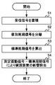
- FIG. 6 is a flowchart showing a flow of processing of the control unit 4 during the steady operation of the epicenter device 50.
- step S1 when the communication unit 2 receives the measurement vibration signal from the vibration receiving device 60, the storage unit 3 stores the received measurement vibration signal. Subsequently, in step S ⁇ b> 2, the separation unit 41 separates the measurement vibration signal into individual periodic signals having a period corresponding to the periodicity of the vibration wave generated by the seismic source device 50.
- step S3 the calculation unit 42 calculates a standard periodic signal from the individual periodic signal. Specifically, the calculation unit 42 calculates the weighted average weighted by the reciprocal of the variance of the frequency component N 2 +0.0025 Hz corresponding to the noise, or the median value of the frequency component N 2 at which the vibration wave generated from the source device 50 appears. Based on the above, a standard periodic signal is calculated. Subsequently, in step S ⁇ b> 4, the generation unit 43 subtracts the standard periodic signal from the measured vibration signal and removes the influence of the epicenter device 50.
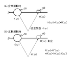
- FIG. 7 is a diagram schematically illustrating such a seismic source device 50
- FIG. 7A shows a perspective view of the seismic source device 50
- FIG. 7B shows a front view of the seismic source device 50.
- the seismic source device 50 generates a vibration wave by precisely controlling and rotating a weight 52 eccentric with respect to the rotation shaft 51 by a servo motor 53.
- the vibration wave in the horizontal direction “X” and the vertical direction “Z” is generated from the seismic source device 50 when the weight 52 is rotated in the forward direction, the weight 52 is moved in the reverse direction.
- the vibration device in the horizontal direction “ ⁇ X” and the vertical direction “Z” is generated from the seismic source device 50. Therefore, the seismic device 50 generates a first vibration wave having a vibration signal having the first polarity in the first period, and inverts the first polarity in the horizontal direction or the vertical direction in the second period having the same length as the first period.
- a second vibration wave having a vibration signal having the second polarity is generated.
- the hypocenter device 50 rotates the weight 52 in the forward direction in the first period to generate vibration waves in the horizontal direction “X” and the vertical direction “Z”, and moves the weight 52 in the reverse direction in the second period. To generate vibration waves in the horizontal direction “ ⁇ X” and the vertical direction “Z”.
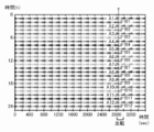
- FIG. 8 an example of the vibration wave generated by the seismic source device 50 is shown in FIG.
- the horizontal axis represents time (seconds), and the vertical axis represents the frequency with a sign of the vibration wave.
- 8A shows the frequency of the vibration wave for one hour when the weight 52 is rotated forward
- FIG. 8B shows the reverse rotation of the weight 52 in the next hour of FIG. 8A.
- the frequency of the vibration wave for 1 hour at the time of making it show is shown.
- the seismic device 50 is in steady operation (forward or reverse rotation) during “0 second to 2800 seconds”, and the seismic device 50 is reversed during “2800 seconds to 3000 seconds”. I have control. Also, during “3000 seconds to 3600 seconds”, the running-in operation (reverse rotation or forward rotation) for the next one hour is performed.
- the vibration wave generated from the hypocenter device 50 during forward rotation and the vibration wave generated from the hypocenter device 50 during reverse rotation are added, the horizontal component of the vibration wave can be removed, and the vibration wave generated from the hypocenter device 50 during forward rotation.
- the vertical component of the vibration wave can be removed.
- the horizontal component of the measurement vibration signal can be removed, and during the forward rotation.
- the transfer function focusing on the vertical or horizontal direction can be calculated. Can be implemented from various viewpoints.
- the vibration wave to be generated can be controlled in a situation where the eccentric weight can be rotated in a certain manner, and the generated vibration wave is reproduced. Sex can be secured.
- the situation in which the eccentric weight can be rotated in a certain manner corresponds to, for example, the steady operation (0 second to 2800 seconds) and the running-in operation (3000 seconds to 3600 seconds) in FIG.
- the eccentric weight needs to be decelerated and stopped, and then accelerated in the reverse direction.
- the vibration wave generated from the seismic source device 50 cannot be precisely controlled, and the reproducibility is lowered.
- the above-described control using the standard periodic signal during steady operation focuses on the periodicity of the vibration wave generated from the seismic source device 50, and is applicable to the reverse operation in which the reproducibility of the vibration wave cannot be ensured reliably. Have difficulty. Therefore, the vibration detection system S of the present invention can detect other vibrations such as natural earthquakes even during the reversal operation of the seismic source device 50 by the following method.
- the vibration wave generated in the inversion period between the first period in which the epicenter device 50 rotates the eccentric weight in the forward direction and the second period in which the eccentric weight rotates in the reverse direction is referred to as a transition vibration wave.
- the calculation unit 42 calculates the median value of the measurement vibration signal based on the transition vibration wave received by the vibration receiving device 60 in a plurality of inversion periods as the standard periodic signal in the inversion period.
- FIG. 9 is a diagram illustrating an example of a measurement vibration signal received by one vibration receiving device 60.
- the calculation unit 42 takes the median value of these plural (12 data) measurement vibration signals and calculates a standard periodic signal in the inversion period. Specifically, the calculation unit 42 calculates the median value of the measured vibration signals A1 to A12 at an arbitrary time T during the inversion period as a standard periodic signal when the normal rotation is reversed to the reverse rotation. Further, the calculation unit 42 calculates the median value of the measurement vibration signals B1 to B12 at an arbitrary time T during the inversion period as a standard periodic signal when the reverse rotation is reversed to the forward rotation.
- the calculation unit 42 subtracts the calculated standard period signal from the measured vibration signal received by the vibration receiving device 60 during the reverse operation, thereby removing the influence of the hypocenter device 50 even during the reverse operation. .
- vibrations of a certain magnitude or more such as natural earthquakes could be detected in all the vibration receiving devices 60.
- the calculation unit 42 calculates the transfer function of the ground from the source device 50 to the vibration receiving device 60 during the steady operation of the source device 50 (during the first period or the second period), and the inversion A standard periodic signal in the inversion period is calculated based on the transition vibration wave during operation and the calculated transfer function.
- the vibration wave generated from the seismic device 50 is not controlled and cannot be grasped in advance.
- the signal processing device 1 is configured to log information about the operation of the seismic device 50 (for example, the position and speed of the eccentric weight). Etc.), the vibration wave actually generated from the hypocenter device 50 can be calculated. Therefore, the calculation unit 42 can acquire the vibration signal f ( ⁇ ) of the vibration wave generated from the seismic source device 50 even during the reversal operation.
- the calculation unit 42 subtracts the standard period signal R ′ ( ⁇ ) calculated in this way from the measured vibration signal R ( ⁇ ) actually received by the vibration receiving device 60 during the reversal operation, thereby enabling precise control. Even during difficult reversal operation, it is possible to remove the influence of the hypocenter device 50 and detect other vibrations such as natural earthquakes.
- the transfer function H ( ⁇ ) changes when viewed strictly. Such changes cannot be ignored due to accumulation of changes when viewed at time intervals such as half a year or one year. However, if a single or a few fractures occur, the level of the vibration wave of the seismic source device 50 It can be ignored enough. Therefore, even if the calculation unit 42 uses the transfer function H ( ⁇ ) calculated during the steady operation in the vicinity of the reverse operation (for example, immediately before 24 hours), the influence of the epicenter device 50 can be removed. Other vibrations such as natural earthquakes can be detected.
- the seismic source device 50 generates a vibration wave that changes between “5 Hz to 50 Hz” during the normal operation in the forward rotation, and “ ⁇ 5 Hz to ⁇ 50 Hz” during the normal operation in the reverse rotation. Generates vibration waves that change between. Therefore, during steady operation, a vibration wave in the range of “ ⁇ 5 Hz to ⁇ 50 Hz” is generated from the seismic source device 50, and the calculation unit 42 transfers the transfer function in the range of “ ⁇ 5 Hz to ⁇ 50 Hz”. H ( ⁇ ) can be calculated.
- the vibration wave of “5 Hz to ⁇ 5 Hz” is sufficiently small, it can be almost ignored except for the vibration receiving device 60 located in the vicinity of the epicenter device 50.
- the vibration wave generated from the epicenter device 50 can be controlled, even if there is a range in which the calculation unit 42 cannot calculate the transfer function H ( ⁇ ), the influence of the epicenter device 50 can be further reduced.
- the range in which the transfer function H ( ⁇ ) cannot be calculated is set to “1 Hz” by setting the vibration wave generated from the seismic source device 50 to “ ⁇ 1 Hz to ⁇ 50 Hz” instead of “ ⁇ 5 Hz to ⁇ 50 Hz”. It can be narrowed to "-1 Hz", and the influence of the hypocenter device 50 can be sufficiently reduced.
- the calculation unit 42 extrapolates the transfer function in the range of “5 Hz to ⁇ 5 Hz” where the transfer function cannot be calculated from the transfer function H ( ⁇ ) in the range of “ ⁇ 5 Hz to ⁇ 50 Hz” calculated during the steady operation. , May be used.
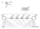
- the active seismic survey using the seismic source device 50 can increase the accuracy by increasing the number of transmission sources and destinations, the active seismic survey may use a plurality of seismic source devices 50. Next, control when using a plurality of seismic source devices 50 will be described.
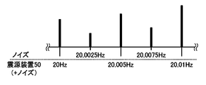
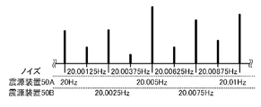
- the hypocenter devices 50A and 50B generate vibration waves having different frequencies.
- the frequency of the vibration wave generated from the seismic device 50A is “N (5 Hz to 50 Hz)”
- the frequency of the vibration wave generated from the seismic device 50B is “N + 0.0025 Hz (5.025 Hz to 50.50). 0025 Hz) ”.
- the separation unit 41 separates the individual periodic signal having a period corresponding to the periodicity of each of the vibration waves generated by the hypocenter devices 50A and 50B from the measured vibration signal received by the vibration receiving device 60.
- the separation unit 41 separates, for example, an individual periodic signal every 800 seconds from the measurement vibration signal.
- produced from the hypocenter apparatus 50A, 50B can be isolate
- the vibration wave spectrum of the seismic device 50A, 50B does not appear at the frequency N + 0.00125, and ground noise, etc.
- the calculation unit 42 calculates the standard periodic signal by weighted average using the inverse of noise variance or the like. Can be calculated.
- FIG. 14 is a diagram illustrating an original waveform (FIG. 14A) of the measurement vibration signal in the vibration receiving device 60G and a signal waveform (FIG. 14B) of the differential signal after the influence removal process.
- the present inventors used a weighted average using the reciprocal of the variance of noise during “0 second to 2800 seconds” during steady operation and “3000 seconds to 3600 seconds” during break-in operation.
- Periodic signals were calculated to eliminate the influence of vibration waves from the hypocenter devices 50A and 50B.
- the present inventors calculate a standard periodic signal from the median value of a plurality (12 data) of measured vibration signals during “2800 seconds to 3000 seconds” during the reverse operation, and influence of vibration waves of the hypocenter devices 50A and 50B. Was removed. Further, the influence removal process is not performed for “3000 seconds to 3600 seconds” at 24:00 for comparison.
- the measurement vibration signal received by the vibration receiving device 60 is separated into individual periodic signals. Since the individual periodic signal is separated for each period according to the periodicity of the vibration wave generated from the seismic source device 50, even if the measurement vibration signal includes other vibration signals such as natural earthquakes, By comparing a plurality of individual periodic signals, a standard periodic signal (standard periodic signal) that does not include other vibration signals can be calculated. Since the influence of other vibration signals such as natural earthquakes is removed from the standard periodic signal calculated in this way and the influence of the vibration signal based on the vibration wave of the seismic source device 50 appears, the measurement periodic signal received by the vibration receiving device 60 is used. By subtracting the standard periodic signal, the influence of the vibration wave of the seismic source device 50 can be removed. Thereby, even when the seismic source device 50 is in operation, the vibration receiving device 60 can detect other vibrations such as a natural earthquake.
- standard periodic signal standard periodic signal
- the seismic source device 50 generates a vibration wave whose frequency changes within a period, so that various geological grounds can be explored.
- the vibration receiving device 60 since there is a significant correlation between the environmental conditions such as weather and temperature and the measurement vibration signal received by the vibration receiving device 60, it is possible to use the standard periodic signal in association with the environmental conditions and store it in rainy weather. However, other vibrations such as natural earthquakes can be detected during operation of the epicenter device 50, which is preferable.
- the first vibration wave having the first polarity vibration signal and the second polarity vibration signal obtained by inverting the first polarity in the horizontal direction or the vertical direction from the source device 50.
- the seismic source device 50 is controlled such that the first period in which the first vibration wave is generated and the second period in which the second vibration wave is generated are repeated.
- the horizontal direction of the vibration wave generated from the seismic source device 50 is obtained by adding and subtracting the measurement vibration signal that is the reception result of the first vibration wave and the measurement vibration signal that is the reception result of the second vibration wave.
- Directional components and vertical components can be removed.
- active seismic exploration can be performed from various viewpoints.
- the generated vibration wave can be precisely controlled during the steady operation of the hypocenter device 50, the generated vibration wave cannot be accurately controlled during the reversal operation in which the polarity is reversed.
- the vibration detection system S is practical by using the median value of the measured vibration signal, which is the reception result of the transition vibration wave during the reverse operation, and the transfer function H ( ⁇ ) calculated during the steady operation. Therefore, the influence of the vibration wave of the seismic source device 50 can be removed with a level of accuracy that can withstand. Therefore, even during the reversal operation of the epicenter device 50, other vibrations such as a natural earthquake can be detected.
- the vibration detection system S even when a plurality of the epicenter devices 50 are provided, the influence of the vibration wave of each seismic source device 50 can be removed, so that active seismic exploration can be performed with high accuracy. it can.
- SYMBOLS 1 Signal processing apparatus, 2 ... Communication part, 3 ... Accumulation part, 4 ... Control part, 41 ... Separation part, 42 ... Calculation part, 43 ... Generation part, 50 ... Earthquake source device, 60 ... Vibration receiving device, S ... Vibration detection system
Landscapes
- Physics & Mathematics (AREA)
- Life Sciences & Earth Sciences (AREA)
- Engineering & Computer Science (AREA)
- Remote Sensing (AREA)
- Environmental & Geological Engineering (AREA)
- Acoustics & Sound (AREA)
- Geology (AREA)
- General Life Sciences & Earth Sciences (AREA)
- General Physics & Mathematics (AREA)
- Geophysics (AREA)
- Business, Economics & Management (AREA)
- Emergency Management (AREA)
- Geophysics And Detection Of Objects (AREA)
Priority Applications (3)
| Application Number | Priority Date | Filing Date | Title |
|---|---|---|---|
| CA2947662A CA2947662C (en) | 2014-05-27 | 2015-05-26 | Vibration detection system, signal processing device, and signal processing method |
| AU2015266532A AU2015266532B2 (en) | 2014-05-27 | 2015-05-26 | Vibration detection system, signal processing device, and signal processing method |
| US15/355,878 US10281601B2 (en) | 2014-05-27 | 2016-11-18 | Vibration detecting system, signal processing apparatus and signal processing method |
Applications Claiming Priority (2)
| Application Number | Priority Date | Filing Date | Title |
|---|---|---|---|
| JP2014108923A JP6347480B2 (ja) | 2014-05-27 | 2014-05-27 | 振動検出システム、信号処理装置及び信号処理方法 |
| JP2014-108923 | 2014-05-27 |
Related Child Applications (1)
| Application Number | Title | Priority Date | Filing Date |
|---|---|---|---|
| US15/355,878 Continuation US10281601B2 (en) | 2014-05-27 | 2016-11-18 | Vibration detecting system, signal processing apparatus and signal processing method |
Publications (1)
| Publication Number | Publication Date |
|---|---|
| WO2015182608A1 true WO2015182608A1 (ja) | 2015-12-03 |
Family
ID=54698933
Family Applications (1)
| Application Number | Title | Priority Date | Filing Date |
|---|---|---|---|
| PCT/JP2015/065110 Ceased WO2015182608A1 (ja) | 2014-05-27 | 2015-05-26 | 振動検出システム、信号処理装置及び信号処理方法 |
Country Status (5)
| Country | Link |
|---|---|
| US (1) | US10281601B2 (enExample) |
| JP (1) | JP6347480B2 (enExample) |
| AU (1) | AU2015266532B2 (enExample) |
| CA (1) | CA2947662C (enExample) |
| WO (1) | WO2015182608A1 (enExample) |
Cited By (2)
| Publication number | Priority date | Publication date | Assignee | Title |
|---|---|---|---|---|
| CN112946728A (zh) * | 2019-12-11 | 2021-06-11 | 中国石油天然气集团有限公司 | 可控震源振动器振动工作保护控制方法及装置 |
| US12032109B2 (en) | 2017-06-08 | 2024-07-09 | Total Sa | Method for acquiring a seismic dataset over a region of interest |
Families Citing this family (6)
| Publication number | Priority date | Publication date | Assignee | Title |
|---|---|---|---|---|
| US10627540B2 (en) * | 2013-12-30 | 2020-04-21 | Pgs Geophysical As | Method for calibrating the far-field acoustic output of a marine vibrator |
| JP6423219B2 (ja) * | 2014-09-24 | 2018-11-14 | 前田建設工業株式会社 | 構造物の安全性診断システム |
| CA3111405A1 (en) * | 2018-09-30 | 2020-04-02 | Conocophillips Company | Machine learning based signal recovery |
| CN111522060A (zh) * | 2020-04-17 | 2020-08-11 | 重庆地质矿产研究院 | 一种页岩气开发区域的地震监测系统 |
| WO2022176717A1 (ja) * | 2021-02-17 | 2022-08-25 | 国立大学法人九州大学 | 地震探査システムおよび地震探査方法 |
| CN113720421B (zh) * | 2021-09-22 | 2023-09-22 | 北京锐达仪表有限公司 | 振动波分层界面测量装置及测量方法 |
Citations (2)
| Publication number | Priority date | Publication date | Assignee | Title |
|---|---|---|---|---|
| WO2011007706A1 (ja) * | 2009-07-17 | 2011-01-20 | エタニ電機株式会社 | インパルス応答測定方法およびインパルス応答測定装置 |
| JP2012108072A (ja) * | 2010-11-19 | 2012-06-07 | Oyo Corp | 鉛直アレイ地震計を利用したq値測定方法 |
Family Cites Families (14)
| Publication number | Priority date | Publication date | Assignee | Title |
|---|---|---|---|---|
| WO2005019865A2 (en) * | 2003-08-11 | 2005-03-03 | Exxonmobil Upstream Research Company | Method for continuous sweeping and separation of multiple seismic vibrators |
| US9519072B2 (en) | 2006-05-11 | 2016-12-13 | Schlumberger Technology Corporation | Method and apparatus for locating gas hydrate |
| US8027223B2 (en) * | 2007-07-16 | 2011-09-27 | Battelle Energy Alliance, Llc | Earth analysis methods, subsurface feature detection methods, earth analysis devices, and articles of manufacture |
| US7639567B2 (en) * | 2007-09-17 | 2009-12-29 | Ion Geophysical Corporation | Generating seismic vibrator signals |
| US7864630B2 (en) * | 2007-11-01 | 2011-01-04 | Conocophillips Company | Method and apparatus for minimizing interference between seismic systems |
| AU2009282411B2 (en) * | 2008-08-11 | 2014-09-18 | Exxonmobil Upstream Research Company | Removal of surface-wave noise in seismic data |
| US8938363B2 (en) * | 2008-08-18 | 2015-01-20 | Westerngeco L.L.C. | Active seismic monitoring of fracturing operations and determining characteristics of a subterranean body using pressure data and seismic data |
| US9213119B2 (en) * | 2008-10-29 | 2015-12-15 | Conocophillips Company | Marine seismic acquisition |
| US9372272B2 (en) * | 2010-12-17 | 2016-06-21 | Seismic Warning Systems, Inc. | Earthquake warning system |
| US9075162B2 (en) * | 2011-11-10 | 2015-07-07 | Pgs Geophysical As | Method and system for separating seismic sources in marine simultaneous shooting acquisition |
| US20140060958A1 (en) * | 2011-12-21 | 2014-03-06 | Conocophillips Company | Heterodyned eccentric vibrator |
| US9405027B2 (en) * | 2012-01-12 | 2016-08-02 | Westerngeco L.L.C. | Attentuating noise acquired in an energy measurement |
| PL2992359T3 (pl) * | 2013-05-01 | 2021-04-19 | Cgg Services Sas | Urządzenie i sposób do pozyskiwania danych sejsmicznych z jednoczesną aktywacją sklastrowanych wibratorów |
| MX367935B (es) * | 2013-11-01 | 2019-09-12 | Cgg Services Sa | Metodo y aparato de des-mezclado hibrido. |
-
2014
- 2014-05-27 JP JP2014108923A patent/JP6347480B2/ja active Active
-
2015
- 2015-05-26 WO PCT/JP2015/065110 patent/WO2015182608A1/ja not_active Ceased
- 2015-05-26 CA CA2947662A patent/CA2947662C/en active Active
- 2015-05-26 AU AU2015266532A patent/AU2015266532B2/en active Active
-
2016
- 2016-11-18 US US15/355,878 patent/US10281601B2/en active Active
Patent Citations (2)
| Publication number | Priority date | Publication date | Assignee | Title |
|---|---|---|---|---|
| WO2011007706A1 (ja) * | 2009-07-17 | 2011-01-20 | エタニ電機株式会社 | インパルス応答測定方法およびインパルス応答測定装置 |
| JP2012108072A (ja) * | 2010-11-19 | 2012-06-07 | Oyo Corp | 鉛直アレイ地震計を利用したq値測定方法 |
Cited By (2)
| Publication number | Priority date | Publication date | Assignee | Title |
|---|---|---|---|---|
| US12032109B2 (en) | 2017-06-08 | 2024-07-09 | Total Sa | Method for acquiring a seismic dataset over a region of interest |
| CN112946728A (zh) * | 2019-12-11 | 2021-06-11 | 中国石油天然气集团有限公司 | 可控震源振动器振动工作保护控制方法及装置 |
Also Published As
| Publication number | Publication date |
|---|---|
| JP6347480B2 (ja) | 2018-06-27 |
| JP2015224916A (ja) | 2015-12-14 |
| AU2015266532A1 (en) | 2016-11-17 |
| CA2947662A1 (en) | 2015-12-03 |
| AU2015266532B2 (en) | 2020-01-30 |
| US20170068004A1 (en) | 2017-03-09 |
| CA2947662C (en) | 2022-11-01 |
| US10281601B2 (en) | 2019-05-07 |
Similar Documents
| Publication | Publication Date | Title |
|---|---|---|
| JP6347480B2 (ja) | 振動検出システム、信号処理装置及び信号処理方法 | |
| Sutherland et al. | Observations of wave dispersion and attenuation in landfast ice | |
| Coviello et al. | Detecting torrential processes from a distance with a seismic monitoring network | |
| Walter et al. | Using glacier seismicity for phase velocity measurements and Green's function retrieval | |
| US10451475B2 (en) | Gauge length optimization in distributed vibration sensing | |
| Kohler et al. | The Community Seismic Network and Quake-Catcher Network: Enabling structural health monitoring through instrumentation by community participants | |
| EP3126878A1 (en) | Downhole surveillance | |
| WO2015025216A2 (en) | Method for monitoring a well or a reservoir containing a fluid, and apparatus for using the same | |
| CN108957544B (zh) | 近地表各向异性参数的测量方法、装置、地震计及介质 | |
| Picozzi et al. | Interferometric analysis of strong ground motion for structural health monitoring: the example of the L’Aquila, Italy, seismic sequence of 2009 | |
| US11940580B2 (en) | Heterogeneous subsurface imaging systems and methods | |
| Peng et al. | Exploring the feasibility of earthquake early warning using records of the 2008 Wenchuan earthquake and its aftershocks | |
| D’hour et al. | Detection of subtle hydromechanical medium changes caused by a small-magnitude earthquake swarm in NE Brazil | |
| Fichtner et al. | Borehole fibre-optic seismology inside the Northeast Greenland Ice Stream | |
| Lotti et al. | Seismic monitoring of a rockslide: The Torgiovannetto quarry (central Apennines, Italy) | |
| Li et al. | Broadband-seismic analysis of a massive landslide in southwestern China: Dynamics and fragmentation implications | |
| Czarny et al. | Spatiotemporal evaluation of Rayleigh surface wave estimated from roadside dark fiber DAS array and traffic noise | |
| RU2570589C1 (ru) | Способ определения эффективных геометрических размеров зоны разлома, заполненной флюидами | |
| JP5517258B2 (ja) | 鉛直アレイ地震計を利用したq値測定方法 | |
| Zhao et al. | Extracting subsurface information based on extremely short period of DAS recordings | |
| Harrington et al. | Analysis of laboratory simulations of volcanic hybrid earthquakes using empirical Green's functions | |
| Johnston et al. | Triggered deformation and seismic activity under Mammoth Mountain in long Valley caldera by the 3 November 2002 M w 7.9 Denali fault earthquake | |
| Liu et al. | Urban Monitoring Using Pre-Existing Telecommunication Fiber-Optic Networks for Distributed Acoustic Sensing: A Review | |
| Li et al. | Near-surface imaging and monitoring enabled by urban distributed acoustic sensing seismic arrays | |
| CN120630303B (zh) | 基于被动源地震数据的地面塌陷监测方法、装置、设备、介质及产品 |
Legal Events
| Date | Code | Title | Description |
|---|---|---|---|
| 121 | Ep: the epo has been informed by wipo that ep was designated in this application |
Ref document number: 15798865 Country of ref document: EP Kind code of ref document: A1 |
|
| ENP | Entry into the national phase |
Ref document number: 2947662 Country of ref document: CA |
|
| ENP | Entry into the national phase |
Ref document number: 2015266532 Country of ref document: AU Date of ref document: 20150526 Kind code of ref document: A |
|
| NENP | Non-entry into the national phase |
Ref country code: DE |
|
| 122 | Ep: pct application non-entry in european phase |
Ref document number: 15798865 Country of ref document: EP Kind code of ref document: A1 |