WO2015182103A1 - 送信装置、受信装置、送信方法および受信方法 - Google Patents
送信装置、受信装置、送信方法および受信方法 Download PDFInfo
- Publication number
- WO2015182103A1 WO2015182103A1 PCT/JP2015/002614 JP2015002614W WO2015182103A1 WO 2015182103 A1 WO2015182103 A1 WO 2015182103A1 JP 2015002614 W JP2015002614 W JP 2015002614W WO 2015182103 A1 WO2015182103 A1 WO 2015182103A1
- Authority
- WO
- WIPO (PCT)
- Prior art keywords
- message
- unit
- network
- identification information
- mac
- Prior art date
Links
Images


Classifications
-
- H—ELECTRICITY
- H04—ELECTRIC COMMUNICATION TECHNIQUE
- H04L—TRANSMISSION OF DIGITAL INFORMATION, e.g. TELEGRAPHIC COMMUNICATION
- H04L9/00—Cryptographic mechanisms or cryptographic arrangements for secret or secure communications; Network security protocols
- H04L9/32—Cryptographic mechanisms or cryptographic arrangements for secret or secure communications; Network security protocols including means for verifying the identity or authority of a user of the system or for message authentication, e.g. authorization, entity authentication, data integrity or data verification, non-repudiation, key authentication or verification of credentials
- H04L9/3236—Cryptographic mechanisms or cryptographic arrangements for secret or secure communications; Network security protocols including means for verifying the identity or authority of a user of the system or for message authentication, e.g. authorization, entity authentication, data integrity or data verification, non-repudiation, key authentication or verification of credentials using cryptographic hash functions
- H04L9/3242—Cryptographic mechanisms or cryptographic arrangements for secret or secure communications; Network security protocols including means for verifying the identity or authority of a user of the system or for message authentication, e.g. authorization, entity authentication, data integrity or data verification, non-repudiation, key authentication or verification of credentials using cryptographic hash functions involving keyed hash functions, e.g. message authentication codes [MACs], CBC-MAC or HMAC
-
- B—PERFORMING OPERATIONS; TRANSPORTING
- B60—VEHICLES IN GENERAL
- B60R—VEHICLES, VEHICLE FITTINGS, OR VEHICLE PARTS, NOT OTHERWISE PROVIDED FOR
- B60R16/00—Electric or fluid circuits specially adapted for vehicles and not otherwise provided for; Arrangement of elements of electric or fluid circuits specially adapted for vehicles and not otherwise provided for
- B60R16/02—Electric or fluid circuits specially adapted for vehicles and not otherwise provided for; Arrangement of elements of electric or fluid circuits specially adapted for vehicles and not otherwise provided for electric constitutive elements
- B60R16/023—Electric or fluid circuits specially adapted for vehicles and not otherwise provided for; Arrangement of elements of electric or fluid circuits specially adapted for vehicles and not otherwise provided for electric constitutive elements for transmission of signals between vehicle parts or subsystems
-
- H—ELECTRICITY
- H04—ELECTRIC COMMUNICATION TECHNIQUE
- H04L—TRANSMISSION OF DIGITAL INFORMATION, e.g. TELEGRAPHIC COMMUNICATION
- H04L12/00—Data switching networks
- H04L12/28—Data switching networks characterised by path configuration, e.g. LAN [Local Area Networks] or WAN [Wide Area Networks]
- H04L12/40—Bus networks
- H04L12/40006—Architecture of a communication node
- H04L12/40026—Details regarding a bus guardian
-
- H—ELECTRICITY
- H04—ELECTRIC COMMUNICATION TECHNIQUE
- H04L—TRANSMISSION OF DIGITAL INFORMATION, e.g. TELEGRAPHIC COMMUNICATION
- H04L63/00—Network architectures or network communication protocols for network security
- H04L63/08—Network architectures or network communication protocols for network security for authentication of entities
- H04L63/0876—Network architectures or network communication protocols for network security for authentication of entities based on the identity of the terminal or configuration, e.g. MAC address, hardware or software configuration or device fingerprint
-
- H—ELECTRICITY
- H04—ELECTRIC COMMUNICATION TECHNIQUE
- H04L—TRANSMISSION OF DIGITAL INFORMATION, e.g. TELEGRAPHIC COMMUNICATION
- H04L63/00—Network architectures or network communication protocols for network security
- H04L63/14—Network architectures or network communication protocols for network security for detecting or protecting against malicious traffic
- H04L63/1408—Network architectures or network communication protocols for network security for detecting or protecting against malicious traffic by monitoring network traffic
- H04L63/1416—Event detection, e.g. attack signature detection
-
- H—ELECTRICITY
- H04—ELECTRIC COMMUNICATION TECHNIQUE
- H04L—TRANSMISSION OF DIGITAL INFORMATION, e.g. TELEGRAPHIC COMMUNICATION
- H04L63/00—Network architectures or network communication protocols for network security
- H04L63/14—Network architectures or network communication protocols for network security for detecting or protecting against malicious traffic
- H04L63/1441—Countermeasures against malicious traffic
- H04L63/1466—Active attacks involving interception, injection, modification, spoofing of data unit addresses, e.g. hijacking, packet injection or TCP sequence number attacks
-
- H—ELECTRICITY
- H04—ELECTRIC COMMUNICATION TECHNIQUE
- H04W—WIRELESS COMMUNICATION NETWORKS
- H04W12/00—Security arrangements; Authentication; Protecting privacy or anonymity
- H04W12/06—Authentication
- H04W12/069—Authentication using certificates or pre-shared keys
-
- H—ELECTRICITY
- H04—ELECTRIC COMMUNICATION TECHNIQUE
- H04L—TRANSMISSION OF DIGITAL INFORMATION, e.g. TELEGRAPHIC COMMUNICATION
- H04L12/00—Data switching networks
- H04L12/28—Data switching networks characterised by path configuration, e.g. LAN [Local Area Networks] or WAN [Wide Area Networks]
- H04L12/40—Bus networks
- H04L2012/40208—Bus networks characterized by the use of a particular bus standard
- H04L2012/40215—Controller Area Network CAN
-
- H—ELECTRICITY
- H04—ELECTRIC COMMUNICATION TECHNIQUE
- H04L—TRANSMISSION OF DIGITAL INFORMATION, e.g. TELEGRAPHIC COMMUNICATION
- H04L12/00—Data switching networks
- H04L12/28—Data switching networks characterised by path configuration, e.g. LAN [Local Area Networks] or WAN [Wide Area Networks]
- H04L12/40—Bus networks
- H04L2012/40267—Bus for use in transportation systems
- H04L2012/40273—Bus for use in transportation systems the transportation system being a vehicle
-
- H—ELECTRICITY
- H04—ELECTRIC COMMUNICATION TECHNIQUE
- H04L—TRANSMISSION OF DIGITAL INFORMATION, e.g. TELEGRAPHIC COMMUNICATION
- H04L2209/00—Additional information or applications relating to cryptographic mechanisms or cryptographic arrangements for secret or secure communication H04L9/00
- H04L2209/84—Vehicles
-
- H—ELECTRICITY
- H04—ELECTRIC COMMUNICATION TECHNIQUE
- H04L—TRANSMISSION OF DIGITAL INFORMATION, e.g. TELEGRAPHIC COMMUNICATION
- H04L67/00—Network arrangements or protocols for supporting network services or applications
- H04L67/01—Protocols
- H04L67/12—Protocols specially adapted for proprietary or special-purpose networking environments, e.g. medical networks, sensor networks, networks in vehicles or remote metering networks
-
- H—ELECTRICITY
- H04—ELECTRIC COMMUNICATION TECHNIQUE
- H04W—WIRELESS COMMUNICATION NETWORKS
- H04W4/00—Services specially adapted for wireless communication networks; Facilities therefor
- H04W4/30—Services specially adapted for particular environments, situations or purposes
- H04W4/40—Services specially adapted for particular environments, situations or purposes for vehicles, e.g. vehicle-to-pedestrians [V2P]
Definitions
- the present invention relates to a transmission device, a reception device, a transmission method, and a reception method in a communication system connected by a bus.
- CAN Controller Area Network
- CAN is a serial communication protocol that employs a bus network. Messages from each node connected to the bus are broadcast to all nodes connected to the bus. The message does not include identification information of the transmission source node and the destination node. Therefore, the receiving node cannot simply determine whether or not the message comes from the correct communication partner.
- a method using a message authentication code (MAC) has been proposed in order to guarantee the integrity of a message or to prevent a replay attack from an unauthorized device connected to the CAN.
- MAC message authentication code
- a method has been proposed in which a MAC for a message is generated each time a normal message is generated and transmitted, and a message including the MAC is transmitted (see, for example, Patent Document 1).
- the present invention provides a technique for improving security in a communication system that transmits broadcast while suppressing an increase in load.
- the transmission device includes a detection unit, a generation unit, and a transmission unit.
- the detecting unit detects whether or not the communication rule of the message broadcast to the network by another transmitting device matches the communication rule of the message held by the transmitting device.
- the generation unit generates an abnormality notification message for notifying that an abnormality has been detected.
- the transmission unit broadcasts the message generated by the generation unit to the network.
- the detection unit detects a match between the communication rule of the message broadcasted to the network by another transmitting device and the communication rule of the message broadcasted by the transmitting device to the network
- the generating unit generates an abnormality notification message.
- the transmission unit broadcasts this abnormality notification message to the network.
- the figure which shows an example of the data frame of the standard format used by CAN The figure which shows an example of a structure of the CAN system which concerns on embodiment of this invention
- the figure which shows the structural example of ECU which concerns on embodiment of this invention Block diagram showing functions required for spoof detection and message transmission of the message processing unit when MAC is transmitted as a separate message in a method that continues control after abnormality detection
- the flowchart which shows the message transmission process after impersonation is detected by the message processing part of FIG.
- Block diagram showing the functions required for message reception of the message processing unit when the main message is received first and the MAC message is received later in a method of continuing control after the abnormality is detected The flowchart which shows the main message reception process by the message processing part of FIG.
- the flowchart which shows the MAC message reception processing by the message processing section of FIG. Block diagram showing functions necessary for message reception of the message processing unit when a MAC message is received first and a main message is received later in a method of continuing control after abnormality detection
- the flowchart which shows the MAC message reception processing by the message processing section of FIG. The flowchart which shows the main message reception process by the message processing part of FIG.
- Block diagram showing functions required for spoof detection and message transmission of the message processing unit when MAC is included in the main message and transmitted in a method that continues control after detecting an abnormality The flowchart which shows the main message transmission process with MAC after the impersonation detection by the message processing part of FIG. Block diagram showing the functions necessary for message reception of the message processing unit when receiving a main message with MAC in a method of continuing control after abnormality detection. The flowchart which shows the main message reception process with MAC by the message processing part of FIG.
- Figure showing format example of fraud notification message The flowchart which shows the impersonation detection process and fraud notification message transmission process by the message processing part of FIG. Block diagram showing the functions necessary for receiving the fraud notification message of the message processing unit in the method of shifting to fail-safe control after detecting an abnormality
- a flowchart showing fraud notification message reception processing by the message processing unit in a method of shifting to fail-safe control after abnormality detection The flowchart which shows the main message reception processing by the message processing section in the system which shifts to fail safe control after abnormality detection
- Timing chart for explaining a second configuration example for detecting impersonation between different CAN systems in the integrated system Timing chart for explaining a third configuration example for detecting impersonation between different CAN systems in the integrated system
- a conventional transmission apparatus generates a MAC every time a normal message is generated and transmitted. In this case, the load on the node increases and the power consumption also increases. Also, since the number of messages increases, the bus occupation rate also increases.
- the embodiment of the present invention is an in-vehicle network in which a plurality of ECUs (Electronic Control Units) mounted in a vehicle are connected as nodes, and a message including a message ID, data, and MAC as an authentication code is included. Regarding what is being broadcast.
- An embodiment of the present invention will be described below by exemplifying a CAN system as such a network.
- the CAN employs a bus network, and a message from each ECU connected to the bus is broadcast to all ECUs connected to the bus.
- the number of ECUs mounted on a single vehicle and the amount of data handled by the ECUs have increased, and the amount of CAN bus traffic has increased.
- the power consumption of the battery is increasing.
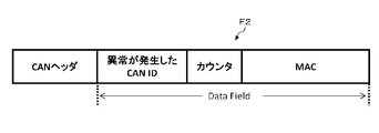
- FIG. 1 is a diagram showing an example of a standard format data frame used in CAN. This data format is described in the following standard document.
- ISO 11898-1 2003 Loader vehicles--Controller area network (CAN)-Part1: Data link layerer and physical signaling
- 1 includes an SOF, an ID field, RTR, IDE, r0, DLC, a data field, a CRC delimiter, an Ack, an Ack delimiter, and an EOF.
- the numbers in each box indicate the number of bits. Also, items whose tops are open are always “0” items, and items whose bottoms are open are always “1”. Items whose top and bottom are not open are items that can take both “0” and “1”.
- the ID field F1 and the data field F2 are mainly focused.
- the ID (hereinafter also referred to as CANID as appropriate) stored in the ID field F1 is identification information indicating the type and priority of the message.
- a data frame in a transmittable state is called a message.
- the message in the CAN is a message related to a specific notification matter of a specific processing target in the vehicle.
- the processing target includes a specific monitoring target and a specific control target.
- a message relating to a specific processing target in the vehicle includes a message including speed information or a message instructing opening / closing of a door.
- a plurality of notification items may be set for the same processing target.
- a plurality of notification items such as a notification item for notifying the engine speed to one meter and a notification item for notifying the engine water temperature can be set.
- CANID is associated with a specific notification item of a specific processing target included in a message to be transmitted.
- the ECU that has received the message determines the content of a specific notification item included in the message based on the CANID.
- the data field F2 can store a maximum of 64 bits of data.
- the CAN data frame does not include a transmission destination ID and a reception destination ID. Therefore, the receiving ECU cannot determine whether the message comes from the correct communication partner. For example, a message including the engine speed is transmitted from the engine ECU.
- a message with the same CANID as the CANID assigned to the message is transmitted from an unauthorized ECU, is the receiving ECU a message from a valid engine ECU or an unauthorized ECU? Cannot be determined. That is, even if an unauthorized ECU impersonates a transmitting ECU and transmits a message containing unauthorized information, the receiving ECU processes the message as a legitimate message and adversely affects subsequent processing (such as control of auxiliary equipment). Will reach. For example, when an unauthorized ECU impersonates an engine ECU and transmits a message including the engine speed, the control of the meter ECU that has received the message is adversely affected.
- the CAN message is authenticated against these threats by using the MAC.
- the MAC is generated by applying a predetermined MAC algorithm to the data to be authenticated and the common key.
- the common key is a secret key shared in advance between ECUs connected to the CAN.
- the MAC generation algorithm includes a method using a hash function (HMAC) and a method using a block encryption algorithm (OMAC / CMAC, CBC-MAC, PMAC).
- HMAC hash function
- OMAC / CMAC, CBC-MAC, PMAC block encryption algorithm
- the receiving ECU calculates the MAC by applying the MAC algorithm used by the transmitting ECU to the authentication target data included in the message and the common key held by itself. If the calculated MAC and the received MAC match, it is determined that the authentication has succeeded, and if they do not match, it is determined that the authentication has failed.
- the common key does not leak, messages from unauthorized ECUs or malicious senders will not be authenticated.
- a replay attack from an unauthorized ECU or the like that has received a valid message and MAC can be dealt with by including a counter value in the data to be authenticated.
- the data length of the MAC generated by the ECU on the transmission side is 64 bits or less. When a MAC exceeding 64 bits is calculated, any 64 bits or less are extracted and used.
- a message that includes information (hereinafter referred to as normal data as appropriate) regarding a specific notification item of a specific processing target and does not include a MAC in a data field is referred to as a main message.
- the main message is a message that is sent for normal processing.
- the normal data corresponds to a control value related to a specific function to be processed.
- a message that does not include normal data in the data field but includes the MAC is called a MAC message.
- a message including both normal data and MAC in the data field is called a main message with MAC.
- the main message, the MAC message, and the main message with MAC are normal messages.
- a fraud notification message In addition to a normal message, there is a message for notifying that a message including a certain CANID is an invalid message.
- this message is referred to as a fraud notification message.
- a message including at least one of the MAC message, the main message with MAC, and the fraud notification message is referred to as an abnormality notification message.
- the abnormality notification message is a message for notifying other ECUs that an abnormality has been detected when an abnormality due to “spoofing” as described above is detected. Details As will be described later, in the following embodiment, when the MAC is received, the receiving ECU can determine the occurrence of an abnormality (injustice due to impersonation), so the MAC message and the main message with MAC are also substantially abnormal notification messages. include.
- the ECU that transmits a message with a certain ID is uniquely determined due to the nature of CAN.
- a method for ensuring security without constantly transmitting MAC using this detection method will be considered.
- FIG. 2 is a diagram showing an example of the configuration of the CAN system 500 according to the embodiment of the present invention.
- a plurality of ECUs 100 (in FIG. 2, ECU1 (100a), ECU2 (100b), ECU3 (100c) and ECU4 (100d)) are connected to the CAN bus 200.
- CSMA / CA Carrier Sense Multiple Access with Collation Avoidance
- the ECU 100 that first started transmission to the CAN bus 200 acquires the transmission right.
- communication arbitration bus arbitration
- a smaller CANID value is given priority.
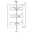
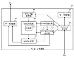
- FIG. 3 is a diagram showing a configuration example of the ECU 100 according to the embodiment of the present invention.
- the ECU 100 includes an application processing unit 10, a message processing unit 30, and a transmission / reception unit 50.
- These configurations can be realized by any processor, memory, and other LSI in terms of hardware, and are realized by programs loaded into the memory in terms of software, but here, functions realized by their cooperation.
- the application processing unit 10 is realized by, for example, a processor, a memory, and an application program loaded in the memory.
- the message processing unit 30 is realized by, for example, a processor, a memory, a message processing program loaded in the memory, and a CAN controller. A configuration in which all functions are mounted on the CAN controller is also possible.
- the transmission / reception unit 50 is realized by a transceiver, for example.
- the application processing unit 10 is connected to a processing target (for example, engine, steering, brake, or other various auxiliary devices) of each ECU 100, and acquires status information or instruction information from these processing targets. Based on the information acquired from the processing target, the application processing unit 10 generates data to be broadcasted by the CAN and passes it to the message processing unit 30. The application processing unit 10 receives data included in the main message or the main message with MAC received from the CAN bus 200 from the message processing unit 30, and processes the processing target according to the data.
- a processing target for example, engine, steering, brake, or other various auxiliary devices
- the message processing unit 30 generates a message when sending a message and analyzes the message when receiving a message. A specific configuration of the message processing unit 30 will be described later.
- the transmission / reception unit 50 broadcasts the message generated by the message processing unit 30 to the CAN bus 200.
- the transmission / reception unit 50 receives a message generated by another ECU 100 and broadcasted to the CAN bus 200 from the CAN bus 200.
- the transmission / reception unit 50 passes the received message to the message processing unit 30.
- the ECU 100 on the regular transmission side detects that a message to be transmitted from the device other than itself is transmitted to another ECU 100
- the ECU 100 on the reception side notifies the ECU 100 on the reception side of the abnormality. .
- a method of continuing control and a method of shifting to fail-safe control for the function to be processed specified by the ID included in the illegal message after detection of the illegal message by the ECU 100 on the regular transmission side can be considered. First, the method of continuing control will be described.
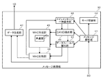
- FIG. 4 is a block diagram illustrating functions necessary for spoofing detection and message transmission of the message processing unit 30 when a MAC is transmitted as a separate message in a method in which control is continued after abnormality detection.
- the message processing unit 30 in FIG. 4 includes a message analysis unit 31, a CANID extraction unit 32, an impersonation detection unit 34, a MAC generation unit 35, a main message generation unit 36, a data field extraction unit 37, and a MAC message generation unit 38.
- FIG. 5 is a flowchart showing impersonation detection processing by the message processing unit 30 of FIG.
- the transmission / reception unit 50 receives a message from the CAN bus 200 and passes it to the message analysis unit 31.
- the CANID extraction unit 32 extracts the CANID from the ID field of the message received by the message analysis unit 31 (S10 in FIG. 5).
- the CANID extraction unit 32 passes the extracted CANID to the impersonation detection unit 34.
- the impersonation detection unit 34 compares the CANID passed from the CANID extraction unit 32 with the CANID that should be included in the message transmitted by the ECU 100 of itself, and detects impersonation (S11).
- impersonation S11
- step S13 If both CANIDs match, it is determined that the received message is a spoofed message.
- the impersonation detection unit 34 When impersonation is detected (Y of S12), the impersonation detection unit 34 notifies the MAC generation unit 35 and the main message generation unit 36 of the occurrence of impersonation (S13).
- impersonation is not detected (N of S12)
- the process of step S13 is skipped.
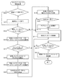
- FIG. 6 is a flowchart showing message transmission processing after impersonation is detected by the message processing unit 30 of FIG.
- the main message generation unit 36 receives a notification of the occurrence of impersonation from the impersonation detection unit 34, the main message generation unit 36 acquires legitimate data regarding the processing target function specified by the spoofed CANID from the application processing unit 10.
- the main message generator 36 stores the acquired data in the data field of the CAN message. Further, the CANID corresponding to the data is stored in the ID field.
- the main message generator 36 determines the values of other items of the CAN message and completes the main message.
- the main message generation unit 36 passes the generated main message to the transmission / reception unit 50, and the transmission / reception unit 50 broadcasts the main message to the CAN bus 200 (S20 in FIG. 6).
- the CANID extraction unit 32 extracts the CANID from the ID field of the transmitted main message (S21).
- the CANID extraction unit 32 passes the extracted CANID to the MAC generation unit 35.
- the data field extraction unit 37 extracts data stored in the data field of the transmitted main message (S22).
- the data field extraction unit 37 passes the extracted data to the MAC generation unit 35.
- the MAC generation unit 35 generates a MAC based on the extracted CANID and data (S23). Specifically, a predetermined MAC algorithm is applied to an authentication target including at least the extracted CANID and data using the held common key 35a. Thereby, the MAC for the authentication target is generated. The MAC generation unit 35 passes the generated MAC to the MAC message generation unit 38.
- the MAC message generator 38 stores the MAC acquired from the MAC generator 35 in the data field of the CAN message. Further, a CANID indicating that the message includes a MAC for the data is stored in the ID field. For example, a value obtained by subtracting a predetermined fixed value from the value of CANID indicating that the message includes the data itself may be used.
- the MAC message generation unit 38 finalizes the values of other items of the CAN message and completes the MAC message.
- the MAC message generation unit 38 passes the generated MAC message to the transmission / reception unit 50, and the transmission / reception unit 50 broadcasts the MAC message to the CAN bus 200 (S24).
- FIG. 6 an example in which a main message including legitimate data of a processing target function specified by a spoofed CANID is transmitted first, and a MAC message including at least the MAC targeting the legitimate data is transmitted later.
- the MAC message may be transmitted first, and the main message may be transmitted later.
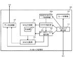
- FIG. 7 is a block diagram showing functions necessary for message reception of the message processing unit 30 when the main message is received first and the MAC message is received later in a manner in which control is continued after abnormality detection.
- functions relating to spoofing detection and message transmission are omitted. 7 includes a message analysis unit 41, a CANID extraction unit 42, a data field extraction unit 43, a mode switching unit 44, a MAC generation unit 45, a MAC comparison unit 46, a data delivery unit 47, and a main message temporary storage unit 48.
- FIG. 8 is a flowchart showing main message reception processing by the message processing unit 30 of FIG.
- the transmission / reception unit 50 receives the main message from the CAN bus 200 and passes it to the message analysis unit 41.
- the message analysis unit 41 determines whether or not the processing target function specified by the CANID included in the main message is in the degeneration mode (S30 in FIG. 8).
- the degeneracy mode in the method of continuing control after detecting an abnormality is a mode in which data related to a specific function of a specific processing target included in the main message is used for processing related to the function on the condition that the MAC has been successfully verified. is there. Therefore, when the verification of the MAC fails, the data regarding the function is discarded without being used. In the normal mode, the data included in the main message is used for processing related to the function without performing MAC verification.
- step S30 if the mode is not the transition to the degenerate mode but the normal mode (N in S30), the data field extraction unit 43 stores the main message received by the message analysis unit 41 in the data field of the main message. The extracted data is extracted and delivered to the data delivery unit 47. The data delivery unit 47 passes the data acquired from the data field extraction unit 43 to the application processing unit 10 (S31). The application processing unit 10 processes the processing target according to the acquired data.
- step S30 when the mode is shifted to the degeneration mode (Y in S30), the message analysis unit 41 does not pass the received main message to the data field extraction unit 43, and the processing is suspended (S32).
- the message analysis unit 41 determines whether the main message is stored in the main message temporary storage unit 48 (S33). If it is held (Y in S33), it is determined whether or not the number of main messages held in the main message temporary holding unit 48 is n or more (S34).
- the message analysis unit 41 discards the oldest main message among the plurality of main messages held in the main message temporary holding unit 48. (S35).
- the message analysis unit 41 stores the received new main message in the main message temporary holding unit 48 (S36). That is, the main message temporary storage unit 48 is managed by a FIFO (FIRST-IN FIRST-OUT).
- the MAC generation process for the data included in the main message stored in the main message temporary storage unit 48 is suspended until an instruction is issued from the message analysis unit 41.
- step S34 when the number of main messages held in the main message temporary holding unit 48 is less than n (N in S34), step S35 is skipped and the message analysis unit 41 receives the received new main message.
- the message is stored in the main message temporary holding unit 48 (S36).
- step S33 when the main message is not held in the main message temporary holding unit 48 (N in S33), the message analysis unit 41 stores the received new main message in the main message temporary holding unit 48 (S36).
- FIG. 9 is a flowchart showing a MAC message reception process by the message processing unit 30 in FIG.
- the transmission / reception unit 50 receives the MAC message from the CAN bus 200 and passes it to the message analysis unit 41.
- the message analysis unit 41 determines whether or not the function to be processed specified by the CANID included in the main message is in the degeneration mode (S40 in FIG. 9).
- the mode switching unit 44 switches from the normal mode to the degeneration mode (S41).
- shifting to the degeneration mode Y in S40
- the degeneration mode is continued. As described above, in the method of continuing the control after the abnormality is detected, the ECU 100 on the receiving side shifts to the degenerate mode at the timing when the MAC is received.
- the message analysis unit 41 determines whether or not the main message is stored in the main message temporary storage unit 48 (S42). If held (Y in S42), the message analysis unit 41 passes the received MAC message to the data field extraction unit 43, and the data field extraction unit 43 extracts the MAC from the data field of the acquired MAC message (S43). ). The data field extraction unit 43 passes the extracted MAC to the MAC comparison unit 46.
- the CANID extraction unit 42 is received by the message analysis unit 41 and stored in the main message temporary storage unit 48.
- CANID is extracted from the ID field of the main message (S45).
- the CANID extraction unit 42 passes the extracted CANID to the MAC generation unit 45.
- the data field extraction unit 43 extracts data stored in the data field of the main message received by the message analysis unit 41 and held in the main message temporary holding unit 48 (S46).
- the data field extraction unit 43 passes the extracted data to the MAC generation unit 45 and the data delivery unit 47.
- the MAC generation unit 45 generates a MAC based on the extracted CANID and data (S47).
- the generation method is the same as the generation method of the MAC generator 35 on the transmission side.
- the MAC generation unit 45 on the reception side holds the same common key 45a as the common key 35a held by the MAC generation unit 35 on the transmission side.
- the MAC generation unit 45 passes the generated MAC to the MAC comparison unit 46.
- the MAC comparison unit 46 compares the MAC generated by the MAC generation unit 45 with the MAC extracted by the data field extraction unit 43 (S48). If both MACs match (Y in S49), the MAC comparison unit 46 determines that the MAC verification is successful, and notifies the data delivery unit 47 that the verification is successful.
- the data field extraction unit 43 extracts data from the data field of the main message that has been successfully verified by the MAC and passes the data to the data transfer unit 47.
- the data delivery unit 47 passes the data passed from the data field extraction unit 43 to the application processing unit 10 (S410).
- the application processing unit 10 processes the processing target according to the acquired data.
- the message analysis unit 41 determines whether or not the main message is stored in the main message temporary storage unit 48 (S412). If held (Y in S412), the message analysis unit 41 discards the message held in the main message temporary holding unit 48 (S413). When the main message is not held in the main message temporary holding unit 48 (N in S412), the process in step S413 is skipped.
- step S49 if the MACs do not match (N in S49), the MAC comparison unit 46 determines that the MAC verification has failed, and notifies the data delivery unit 47 that the verification has failed.
- the data delivery unit 47 does not pass the data passed from the data field extraction unit 43 to the application processing unit 10.
- the message analysis unit 41 discards the received MAC message (S411).
- step S44 when the MAC of the main message held in the main message temporary holding unit 48 has been generated (Y in S44), the processes in steps S45 to S47 are skipped.
- step S42 when the main message is not held in the main message temporary holding unit 48 (N in S42), the message analysis unit 41 discards the received MAC message (S411).
- main message temporary holding unit 48 When a plurality of main messages are held in the main message temporary holding unit 48 when a MAC message is received, MACs are generated in order from the new main message and compared with the MAC included in the received MAC message. . When a main message corresponding to the received MAC message is found, processing corresponding to the data included in the main message is executed. At the same time, the remaining main message held in the main message temporary holding unit 48 is discarded.
- FIG. 10 is a block diagram showing functions necessary for message reception by the message processing unit 30 when a MAC message is received first and a main message is received later in a method in which control is continued after abnormality detection.
- functions relating to spoofing detection and message transmission are omitted.
- the message processing unit 30 in FIG. 10 has a configuration in which the main message temporary holding unit 48 of the message processing unit 30 in FIG. 7 is replaced with a MAC message temporary holding unit 48a.
- FIG. 11 is a flowchart showing a MAC message reception process by the message processing unit 30 in FIG.
- the transmission / reception unit 50 receives the MAC message from the CAN bus 200 and passes it to the message analysis unit 41.
- the message analysis unit 41 determines whether or not the processing target function specified by the CANID included in the MAC message is in the degenerate mode (S50 in FIG. 11).
- the mode switching unit 44 switches from the normal mode to the degeneration mode (S51).
- shifting to the degeneration mode Y in S50
- the degeneration mode is continued.
- the message analysis unit 41 determines whether the number of MAC messages held in the MAC message temporary holding unit 48a is n or more (S52).
- the message analysis unit 41 discards the oldest MAC message among the plurality of MAC messages held in the MAC message temporary holding unit 48a. (S53).
- the message analysis unit 41 stores the received new MAC message in the MAC message temporary holding unit 48a (S54). That is, the MAC message temporary storage unit 48a is managed by a FIFO (FIRST-IN FIRST-OUT).
- step S52 when the number of MAC messages held in the MAC message temporary holding unit 48a is less than n (N in S52), step S53 is skipped, and the message analysis unit 41 receives the received new MAC message. It is stored in the MAC message temporary holding unit 48a (S54).
- the data field extraction unit 43 extracts the MAC stored in the data field of the previously received MAC message and passes it to the MAC comparison unit 46 (S55).
- FIG. 12 is a flowchart showing main message reception processing by the message processing unit 30 in FIG.
- the transmission / reception unit 50 receives the main message from the CAN bus 200 and passes it to the message analysis unit 41.
- the message analysis unit 41 determines whether or not the processing target function specified by the CANID included in the main message is in the degeneration mode (S60 in FIG. 12).
- the CANID extraction unit 42 extracts the CANID from the ID field of the main message received by the message analysis unit 41. (S62). The CANID extraction unit 42 passes the extracted CANID to the MAC generation unit 45. The data field extraction unit 43 extracts the data stored in the data field of the main message received by the message analysis unit 41 (S63). The data field extraction unit 43 passes the extracted data to the MAC generation unit 45 and the data delivery unit 47.
- the MAC generation unit 45 generates a MAC based on the extracted CANID and data (S64).
- the MAC generation unit 45 passes the generated MAC to the MAC comparison unit 46.
- the MAC comparison unit 46 compares the MAC generated by the MAC generation unit 45 with the MAC extracted from the data field of the MAC message by the data field extraction unit 43 (S65). If both MACs match (Y in S66), the MAC comparison unit 46 determines that the MAC verification is successful and notifies the data delivery unit 47 that the verification is successful.
- the data delivery unit 47 receives the notification, the data delivery unit 47 passes the data that has been passed from the data field extraction unit 43 and has been suspended to the application processing unit 10 (S67).
- the application processing unit 10 processes the processing target according to the acquired data.
- step S66 if both MACs do not match (N in S66), the MAC comparison unit 46 determines that the MAC verification has failed and notifies the data delivery unit 47 that the verification has failed. The data delivery unit 47 does not pass the data passed from the data field extraction unit 43 to the application processing unit 10. If the MAC message has not been received in step S61 (N in S61), the message analysis unit 41 discards the received main message (S68). If it is determined in step S60 that the mode is not shifted to the degeneration mode (N in S60), steps S61 to S66 are skipped, and the data extracted from the received main message is passed to the application processing unit 10 (S67). The application processing unit 10 processes the processing target according to the acquired data.
- the MAC messages are compared with the MAC generated from the data included in the main message in order from the new MAC. When the MACs match, processing corresponding to the data included in the main message is executed. At the same time, the remaining MAC messages held in the MAC message temporary holding unit 48a are discarded.
- FIG. 13 is a block diagram illustrating functions necessary for spoofing detection and message transmission of the message processing unit 30 when a MAC is included in a main message and transmitted by a method of continuing control after abnormality detection.
- functions related to reception are omitted.
- the message processing unit 30 in FIG. 13 has a configuration in which the MAC message generation unit 38 is omitted from the message processing unit 30 in FIG. 4.
- FIG. 14 is a flowchart showing main message transmission processing with a MAC after spoofing detection by the message processing unit 30 of FIG.
- the main message generation unit 36 receives the notification of the occurrence of impersonation from the impersonation detection unit 34, the main message generation unit 36 acquires legitimate data regarding the processing target function specified by the spoofed CANID from the application processing unit 10.
- the main message generator 36 stores the acquired data in the data field of the CAN message and generates a main message (S20a).
- the CANID extraction unit 32 extracts the CANID from the ID field of the generated main message (S21a). The CANID extraction unit 32 passes the extracted CANID to the MAC generation unit 35. The data field extraction unit 37 extracts data stored in the data field of the generated main message (S22a). The data field extraction unit 37 passes the extracted data to the MAC generation unit 35.
- the MAC generation unit 35 generates a MAC based on the extracted CANID and data (S23a).
- the MAC generation unit 35 passes the generated MAC to the main message generation unit 36.
- the main message generator 36 additionally stores the MAC acquired from the MAC generator 35 in the data field of the main message.
- the main message generation unit 36 passes the MAC-added main message to which the MAC is added to the transmission / reception unit 50, and the transmission / reception unit 50 broadcasts the MAC-added main message to the CAN bus 200 (S24a).
- FIG. 15 is a block diagram showing functions necessary for message reception of the message processing unit 30 when receiving a main message with MAC by a method of continuing control after detecting an abnormality.
- functions related to spoofing detection and message transmission are omitted.
- the message processing unit 30 in FIG. 15 has a configuration in which the main message temporary storage unit 48 of the message processing unit 30 in FIG. 7 is omitted. Further, the MAC message temporary holding unit 48a of the message processing unit 30 in FIG. 10 is also omitted.
- FIG. 16 is a flowchart showing main message reception processing with MAC by the message processing unit 30 of FIG.
- the transmission / reception unit 50 receives a message from the CAN bus 200 and passes it to the message analysis unit 41.
- the message analysis unit 41 determines whether or not a MAC is included in the message acquired from the transmission / reception unit 50 (S398 in FIG. 16). Whether or not the MAC is included can be determined, for example, by referring to a data length code (DLC), CANID, or a flag indicating whether or not the MAC is included in the data field.
- DLC data length code
- CANID a flag indicating whether or not the MAC is included in the data field.
- the message analysis unit 41 determines whether the function to be processed specified by the CANID included in the received main message with MAC is shifting to the degenerate mode (S40). .
- the mode switching unit 44 switches from the normal mode to the degeneration mode (S41).
- shifting to the degeneration mode Y in S40
- the degeneration mode is continued.
- the CANID extraction unit 42 extracts the CANID from the ID field of the main message with MAC received by the message analysis unit 41 (S45a).
- the CANID extraction unit 42 passes the extracted CANID to the MAC generation unit 45.
- the data field extraction unit 43 extracts the MAC and data from the data field of the main message with MAC received by the message analysis unit 41 (S46a).
- the data field extraction unit 43 passes the extracted MAC to the MAC comparison unit 46 and passes the extracted data to the MAC generation unit 45 and the data delivery unit 47.
- the MAC generation unit 45 generates a MAC based on the extracted CANID and data (S47).
- the MAC comparison unit 46 compares the MAC generated by the MAC generation unit 45 with the MAC extracted by the data field extraction unit 43 (S48). If both MACs match (Y in S49), the MAC comparison unit 46 determines that the MAC verification is successful, and notifies the data delivery unit 47 that the verification is successful.
- the data delivery unit 47 passes the data passed from the data field extraction unit 43 to the application processing unit 10 (S410).
- the application processing unit 10 processes the processing target according to the acquired data.
- step S49 if the MACs do not match (N in S49), the MAC comparison unit 46 determines that the MAC verification has failed, and notifies the data delivery unit 47 that the verification has failed. The data delivery unit 47 does not pass the data passed from the data field extraction unit 43 to the application processing unit 10.
- the message analysis unit 41 determines whether the processing target function specified by the CANID included in the received message is in the degenerate mode. Determine (S399).
- the data field extraction unit 43 extracts the data stored in the data field of the message received by the message analysis unit 41 and passes it to the data transfer unit 47. .
- the data delivery unit 47 passes the data acquired from the data field extraction unit 43 to the application processing unit 10 (S410).
- the application processing unit 10 processes the processing target according to the acquired data.
- step S399 when the mode is shifted to the degeneration mode (Y in S399), the data included in the message received by the message analysis unit 41 is not passed to the application processing unit 10. The received message is discarded or temporarily held in a message temporary holding unit (not shown).
- the method of transmitting the MAC including the main message described above is effective when the amount of normal data to be transmitted is small.
- the method of transmitting the MAC including the main message has an effect of basically reducing the number of messages compared with the method of transmitting the MAC by another message.
- the method of transmitting the MAC in a separate message usually simplifies the processing of the message processing unit 30. Therefore, the method of transmitting the MAC including the main message is not necessarily more advantageous than the method of transmitting the MAC with another message. Therefore, it is preferable to set both of them properly in consideration of the amount of normal data.
- the legitimate transmitting ECU 100 that detects the fraud message transmits the fraud notification message.
- the receiving ECU 100 shifts to a predetermined degeneration mode and performs fail-safe control.
- the degenerate mode in the method of continuing control after detecting an abnormality means a mode in which data related to a specific function included in the main message is used for processing the function on the condition that the MAC has been successfully verified.
- the degeneration mode in the method of shifting to fail-safe control after detecting an abnormality does not trust the data value related to the specific function included in the main message of CANID notified by the fraud notification message, and fails in a prescribed manner. It means a mode for safe control. Fail safe control is control performed in accordance with a default value that is defined in advance in consideration of safety in order to safely process a specific function of a specific processing target.
- control values relating to all processing objects in the vehicle may be set to default values that are defined in advance in consideration of safety so that the vehicle can be safely stopped.
- FIG. 17 is a block diagram showing functions necessary for impersonation detection and fraud notification message transmission of the message processing unit 30 in a method of shifting to fail-safe control after abnormality detection.
- functions related to reception are omitted. 17 includes a message analysis unit 31, a CANID extraction unit 32, an impersonation detection unit 34, a MAC generation unit 35, a fraud notification message generation unit 36a, a data field extraction unit 37, and a counter value storage unit 39.
- FIG. 18 is a diagram showing a format example of the fraud notification message.
- the format of the fraud notification message is the same as the format of the CAN message in FIG.
- the CAN header in FIG. 18 corresponds to SOF to DLC in FIG.
- the data field F2 in FIG. 18 stores a CANID in which an abnormality has occurred, a counter value for preventing a retransmission attack, and a MAC.
- the MAC is a MAC generated for the CANID and the counter value.
- the CANID is a CANID included in an unauthorized message detected by the impersonation detection unit 34.
- the counter value the number of times each CANID message is transmitted in each ECU 100 can be used.
- the counter value storage unit 39 stores the number of transmissions of each CANID message as a counter value. That is, every time a message with a certain CANID is transmitted, the counter value of the CANID is incremented. As the counter value stored in the data field F2, the number of transmissions of the abnormality notification message is used.
- the format of data stored in the data field F2 of the fraud notification message is not limited to the example of FIG.
- a format that does not include a counter value is also possible.
- the counter value storage unit 39 in FIG. 17 is not necessary.
- a random number may be used instead of the counter value.
- the data field F2 of the fraud notification message only needs to include information for specifying the CANID in which an abnormality has occurred, and a format that does not include the CANID itself is also possible.
- FIG. 19 is a flowchart showing spoofing detection processing and fraud notification message transmission processing by the message processing unit 30 of FIG.
- the transmission / reception unit 50 receives a message from the CAN bus 200 and passes it to the message analysis unit 31.
- the CANID extraction unit 32 extracts the CANID from the ID field of the message received by the message analysis unit 31 (S10 in FIG. 19).
- the CANID extraction unit 32 passes the extracted CANID to the impersonation detection unit 34.
- the impersonation detection unit 34 compares the CANID passed from the CANID extraction unit 32 with the CANID that should be included in the message transmitted by the ECU 100 of itself, and detects impersonation (S11). If both CANIDs match, it is determined that the received message is a spoofed message. When impersonation is detected (Y of S12), the impersonation detection unit 34 notifies the fraud notification message generation unit 36a of the occurrence of impersonation (S14).
- the fraud notification message generation unit 36a generates data including the CANID in which impersonation is detected, stores the data in the data field of the fraud notification message (S15), and passes the data to the MAC generation unit 35.
- the data is generated by a combination of a CANID in which spoofing is detected and a counter value indicating the number of times the CANID message is transmitted.
- the MAC generator 35 generates a MAC based on the data generated by the fraud notification message generator 36a (S16).
- the MAC generation unit 35 passes the generated MAC to the fraud notification message generation unit 36a.
- the fraud notification message generator 36a additionally stores the MAC generated by the MAC generator 35 in the data field of the fraud notification message (S17).
- the fraud notification message generation unit 36a passes the generated fraud notification message to the transmission / reception unit 50, and the transmission / reception unit 50 broadcasts the fraud notification message to the CAN bus 200 (S18).
- FIG. 20 is a block diagram showing functions necessary for the message processing unit 30 to receive the fraud notification message in a method of shifting to fail-safe control after detecting an abnormality.
- functions relating to spoofing detection and message transmission are omitted.
- the message processing unit 30 in FIG. 20 has a configuration in which a counter value storage unit 49 is added to the message processing unit 30 in FIG.
- the counter value storage unit 49 stores the number of receptions of each CANID message as a counter value. That is, each time a message with a CANID is received and the MAC verification is successful, the counter value of the CANID is incremented.
- FIG. 21 is a flowchart showing fraud notification message reception processing by the message processing unit 30 in a method of shifting to fail-safe control after abnormality detection.
- the transmission / reception unit 50 receives the fraud notification message from the CAN bus 200 and passes it to the message analysis unit 41.
- the data field extraction unit 43 extracts the data field of the fraud notification message received by the message analysis unit 41 (S70 in FIG. 20).
- the data field extraction unit 43 separates data and MAC included in the extracted data field (S71).
- the data field extraction unit 43 passes the extracted and separated data to the MAC generation unit 45, and passes the extracted and separated MAC to the MAC comparison unit 46.
- the MAC generation unit 45 generates a MAC based on the CANID in which the abnormality included in the separated data has occurred and the counter value of the CANID acquired from the counter value storage unit 49 (S72). The MAC generation unit 45 passes the generated MAC to the MAC comparison unit 46.
- the counter value included in the data field of the received fraud notification message may be used as it is as the counter value.
- the counter value stored in the counter value storage unit 49 is By updating to the value of the received counter value, it is possible to prevent the counter value from being shifted between the transmission-side ECU and the reception-side ECU.
- the received counter value is larger than the counter value of the CANID acquired from the counter value storage unit 49, and is smaller than the counter value of the CANID acquired from the counter value storage unit 49 plus an arbitrary value. For example, only the counter values within the range are to be updated.
- the MAC comparison unit 46 compares the MAC generated by the MAC generation unit 45 with the MAC extracted and separated by the data field extraction unit 43 (S73). If both MACs match (Y in S74), the mode switching unit 44 shifts from the normal mode to the degenerate mode (fail-safe control) (S75). If both MACs do not match (N in S74), the normal mode is maintained.
- FIG. 22 is a flowchart showing main message reception processing by the message processing unit 30 in a method of shifting to fail-safe control after abnormality detection.
- the transmission / reception unit 50 receives the main message from the CAN bus 200 and passes it to the message analysis unit 41.
- the message analysis unit 41 determines whether or not the processing target function specified by the CANID included in the message is in the degenerate mode (S80 in FIG. 22).
- the data included in the received main message is passed to the application processing unit 10, and the application processing unit 10 selects the processing target according to the passed data.
- Process S81
- the message analysis unit 41 discards the received main message (S82).
- the failsafe control is maintained for the processing target function specified by the CANID included in the message.
- a MAC message, a main message with MAC, or a fraud notification message is transmitted.
- security can be improved without generating and transmitting a MAC each time a message including normal data is transmitted. Since constant MAC generation and transmission processing is not required, it is possible to reduce the processing load for MAC generation and MAC verification in each ECU 100. Further, an increase in the occupation ratio of the CAN bus 200 can be suppressed.
- the fraud notification message is generated in the normal CAN message format, it can be implemented without changing the hardware resources such as the CAN controller and without changing the processing contents defined in the standard. Therefore, the introduction cost can be kept low.
- step S70 the processing in the ECU 100 on the receiving side is the same from step S70 to step S73 shown in FIG. 21, and the MAC comparison unit 46 extracts and separates the MAC generated by the MAC generation unit 45 and the data field extraction unit 43. If the MACs of the two match, it is determined that the verification of the MAC has been successful, and the mode shifts to the degenerate mode in the “method of continuing control”.
- the transmission side ECU 100 transmits the main message and the MAC message separately, and transmits the main message with MAC. There is a case.
- the configuration and processing flow of the functions necessary for message transmission by the message processing unit 30 are the same as those shown in FIGS.
- the configuration and processing flow of functions necessary for message transmission by the message processing unit 30 are the same as those shown in FIGS. 13 and 14.
- the receiving side ECU 100 may receive the main message first, receive the MAC message later, receive the MAC message first, receive the main message later, and receive the main message with MAC. is there.
- any ECU 100 receives a plurality of messages each having a different CANID and shifts to a "continue control method" after detecting an abnormality for the plurality of messages, after the shift Furthermore, you may transfer to "the system which transfers to fail safe control".
- the transmission-side ECU 100 periodically transmits the MAC, and the reception-side ECU 100 Is a case where the verification of the MAC fails at the timing when the MAC should be received.
- the sending ECU 100 periodically sends the MAC, and the receiving ECU 100 In FIG. 5, the MAC is not transmitted from the ECU 100 on the transmission side at the timing when the MAC should be received.
- a configuration may be adopted in which a MAC is added to a CANID message to be transmitted for the first time and transmitted. According to this configuration, it is possible to detect an abnormal state caused by falsification or unauthorized removal of the legitimate ECU 100 at the time of starting the system and to ensure safety.
- an event that the ECU 100 itself does not receive the CANID originally transmitted by the ECU 100 on the transmission side is defined as a preset rule, and an event that violates this rule (in this case, the CANID that is originally transmitted) ) Is described as an abnormality (or fraud detected).
- a preset (or prescribed) rule is referred to as a communication rule
- a communication rule there are several other types of the communication rule. For example, the following can be applied.
- the communication rule there is an example in which the ECU 100 on the transmission side holds a cycle in which a message of an arbitrary CANID is transmitted to the CAN bus 200 as a communication rule.
- the cycle in which the message of the CANID is transmitted does not match the cycle set in advance as a communication rule, this can be detected as an invalid message.
- the communication rule there is an example in which the ECU 100 on the transmission side holds the maximum frequency at which a message with an arbitrary CANID is transmitted to the CAN bus 200 as a communication rule.
- the frequency at which the CANID message is transmitted does not match the maximum frequency set in advance as a communication rule, this can be detected as an invalid message.
- the ECU 100 on the transmission side holds the message format of a certain CANID as the communication rule.
- the format includes the data size of the message.
- the data size of the message of the CANID transmitted to the CAN bus 200 does not match the data size set in advance as a communication rule, it can be detected as illegal.
- the communication rule there is an example in which the ECU 100 on the transmission side holds the range of data value included in a certain CANID message, the amount of change, and the like as the communication rule.
- the value of the data included in the CANID message transmitted to the CAN bus 200 in the CANID message does not match the value specified in advance as a communication rule, this is detected as illegal. Is possible.
- the CAN system 500 including the single CAN bus 200 has been described.
- an example of extending a plurality of CAN systems to an integrated system connected via a gateway device will be described.
- the gateway device may become a message sender.
- the gateway apparatus once receives this message and then retransmits (transfers) the message to the other CAN system. In the other CAN system, the gateway apparatus becomes the sender of the message.
- an illegal message transmission is detected by monitoring whether a message having an ID that should be transmitted to another ECU is transmitted. I can't do that. Therefore, in an integrated system in which a plurality of CAN systems are connected via a gateway device, it can be dealt with by using a white list stored in the gateway device. Details will be described below.
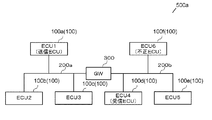
- FIG. 23 is a diagram illustrating a configuration example of an integrated system 500 a in which two CAN systems are connected via the gateway device 300.
- ECU1 100a
- ECU2 100b
- ECU3 100c
- An ECU 4 100d
- an ECU 5 100e
- an ECU 6 100f
- Gateway device 300 is connected between first CAN bus 200a and second CAN bus 200b.
- the gateway device 300 is disposed between the first CAN bus 200a and the second CAN bus 200b in order to prevent an increase in communication traffic, for example.
- the gateway device 300 holds a white list 310.
- the white list includes a message that is permitted in advance to be transferred to a different CAN system via the gateway device 300, and a transfer direction of the message ("from the first CAN bus 200a to the second CAN bus 200b" or "second CAN
- the message transmission direction such as “from the bus 200b to the first CAN bus 200a” and the CANID of the message are associated with each other and stored (stored).
- FIG. 24 shows an example of the white list 310 held by the gateway device 300 of FIG.
- CANIDs of messages permitting transfer from the first CAN bus 200a to the second CAN bus 200b are registered.
- the transfer directions are all from the first CAN bus 200a to the second CAN bus 200b (however, as described above, they may be individually associated with each message).
- the gateway apparatus 300 When the gateway apparatus 300 receives the message of the CANID registered in the white list 310 from the first CAN bus 200a, the gateway apparatus 300 transfers the message to the second CAN bus 200b. Specifically, the gateway device 300 once receives the message of the CANID transmitted to the first CAN bus 200a, and retransmits the message to the second CAN bus 200b. Therefore, on the second CAN bus 200b, the gateway device 300 becomes the sender of the message.
- it is correct to send a message from the ECU 1 (100a) to the ECU 4 (100d) and the ECU 5 (100e) via the gateway device 300.
- the message transmission from the ECU 6 (100f) to the ECU 4 (100d) and the ECU 5 (100e) is a process in the system connected by the second CAN bus 200b which is a single CAN bus
- the ECU 6 (100f ) To the ECU 1 (100a) via the gateway device 300. Therefore, the gateway device 300 detects impersonation of an unauthorized ECU using the white list. The impersonation detection process and the response process after detection will be described in detail below.
- the gateway device 300 after the gateway device 300 detects impersonation, the gateway device 300 responds to an abnormality. That is, the gateway device 300 is an example in which the spoofing detection function and the message transmission function in the message processing unit 30 of the ECU 100 are mounted.
- FIG. 25 is a timing chart for explaining a first configuration example for detecting impersonation between different CAN systems in the integrated system 500a.
- the gateway device 300 receives the spoofing message and detects an abnormality (P11).
- the gateway device 300 executes an abnormality handling process (P12). For example, when a message having the same CAN ID as the CAN ID registered in the white list 310 is received from the second CAN bus 200b, it can be determined that there is an abnormality.
- the gateway device 300 transmits the above-described fraud notification message to the second CAN bus 200b as an abnormality handling process.
- a process for transmitting a main message including legitimate data and a MAC message corresponding to the main message may be considered as an abnormality handling process.
- the gateway device 300 needs to collect valid data regarding each function from the ECU 1 (100a), the ECU 2 (100b), and the ECU 3 (100c). Therefore, the process for sending the above-described fraud notification message is simpler as the abnormality handling process.
- the gateway device 300 since the gateway device 300 detects impersonation and takes an abnormality, the immediate response is high.
- the gateway device 300 transfers a spoof message to the first CAN bus 200a to which the ECU 1 (100a), which is a regular transmission ECU, is connected, and the regular transmission ECU performs an abnormality response.
- the second configuration example can be realized by setting all CANID messages registered in the white list 310 held by the gateway device 300 to be bidirectionally transferred.
- FIG. 26 shows an example of the white list 310 when the second configuration example for detecting impersonation in the integrated system 500a is adopted.
- the CANID message registered in the white list 310 is transferred bi-directionally between the first CAN bus 200a and the second CAN bus 200b. However, normally, since the CANID message is not transmitted from the ECU connected to the second CAN bus 200b, the transfer process from the second CAN bus 200b to the first CAN bus 200a does not occur. Transfer processing from the second CAN bus 200b to the first CAN bus 200a occurs only when an unauthorized impersonation message is transmitted from the ECU connected to the second CAN bus 200b.
- FIG. 27 is a timing chart for explaining a second configuration example for detecting impersonation between different CAN systems in the integrated system 500a.
- the gateway device 300 receives the spoofing message and transfers it to the first CAN bus 200a (P21).
- ECU1 (100a) which is a legitimate transmission ECU detects the abnormality by detecting the impersonation message (P22), and executes the abnormality handling process (P23).
- the ECU 1 (100a) transmits an abnormality handling message such as a message including valid data, and the gateway device 300 receives the abnormality handling message and transfers it to the second CAN bus 200b (P24).
- the second configuration example since only the white list 310 needs to be improved, the addition of functions of the gateway device 300 can be minimized.
- the gateway device 300 detects impersonation and notifies the ECU 1 (100a), which is a normal transmission ECU, so that the normal transmission ECU performs an abnormality response.
- Gateway device 300 is equipped with an impersonation detection function in message processing unit 30 of ECU 100. Further, it is assumed that the gateway device 300 holds the white list 310 of FIG.
- FIG. 28 is a timing chart for explaining a third configuration example for detecting impersonation between different CAN systems in the integrated system 500a.
- the gateway device 300 receives the message and detects an abnormality (P31).
- gateway device 300 transmits an impersonation detection notification to ECU 1 (100a), which is a regular transmission ECU.
- This spoofing detection notification is a message newly generated by the gateway device 300.
- the message is a message that conforms to the format of the CAN message.
- ECU1 (100a) will perform abnormality handling processing, if the said impersonation detection notification is received (P32).
- the ECU 1 (100a) transmits an abnormality response message such as a message including valid data, and the gateway device 300 receives the abnormality response message and transfers it to the second CAN bus 200b (P33).
- the abnormality handling process can be entrusted to a regular transmission ECU without rewriting the white list 310.
- One embodiment of the present invention is a transmission device.
- This apparatus includes a detection unit, a generation unit, and a transmission unit.
- the detection unit detects whether or not the communication rule of a message broadcast to another network by another transmission device matches the communication rule of the message held by the transmission device.
- the generation unit generates an abnormality notification message for notifying that an abnormality has been detected.
- the transmission unit broadcasts the message generated by the generation unit to the network.
- the detection unit detects a match between the communication rule of the message broadcasted to the network by another transmitting device and the communication rule of the message broadcasted by the transmitting device to the network
- the generating unit generates an abnormality notification message. To do. Then, the transmission unit broadcasts this abnormality notification message to the network.
- a fraud notification message is transmitted to notify other devices connected to the network of the occurrence of fraud.
- Security can be improved.
- the unauthorized message detection process and the unauthorized notification message transmission process are lightly loaded processes, and an increase in the load on the transmission apparatus can be suppressed.
- This apparatus includes a detection unit, a generation unit, and a transmission unit.
- the detection unit detects whether or not the identification information included in the message broadcasted to the network by another transmitting apparatus matches the identification information to be included in the message broadcasted to the network by the transmitting apparatus.
- the generation unit generates an abnormality notification message for notifying that an abnormality has been detected.
- the transmission unit broadcasts the message generated by the generation unit to the network.
- the detection unit detects a match between the identification information included in the message broadcast to the network by another transmission device and the identification information to be included in the message broadcast by the transmission device to the network
- the generation unit Generate a notification message. Then, the transmission unit broadcasts this abnormality notification message to the network.
- the “identification information” may be a CANID.
- the “detection unit” may be the impersonation detection unit 34 of FIG.
- the “generation unit” may be the fraud notification message generation unit 36a in FIG. 17, the main message generation unit in FIG. 13, or the MAC message generation unit 38 in FIG.
- the “transmission unit” may be the transmission / reception unit 50 of FIG.
- a fraud notification message is transmitted to notify other devices connected to the network of the occurrence of fraud, and security of other devices. Can be improved. Further, the unauthorized message detection process and the unauthorized notification message transmission process are lightly loaded processes, and an increase in the load on the transmission apparatus can be suppressed.
- the apparatus includes a first generation unit, a second generation unit, and a transmission unit.
- the first generating unit When the identification information included in the message broadcasted to the network by another transmitting device matches the identification information to be included in the message broadcasted by the transmitting device to the network, the first generating unit, A message including legitimate data regarding the notification matter to be processed specified by the identification information is generated.
- the second generation unit generates a message authentication code for at least valid data.
- the transmission unit broadcasts the message generated by the first generation unit and the message authentication code generated by the second generation unit to the network.
- the “identification information” may be a CANID.
- the “first generator” may be the main message generator 36 of FIG.
- the “second generation unit” may be the MAC generation unit 35 of FIG.
- the “transmission unit” may be the transmission / reception unit 50 of FIG.
- a message including identification information to be included in a message transmitted by itself when a message including identification information to be included in a message transmitted by itself is received, a message including legitimate data and a MAC are transmitted to notify other devices connected to the network of the occurrence of fraud.
- the security of other devices can be improved.
- an increase in the load on the transmission device can be suppressed by not generating and transmitting the MAC.
- This apparatus includes a message generation unit and a transmission unit.
- the message generation unit generates a message including identification information associated with a specific notification item to be processed and data related to the notification item.
- the transmission unit broadcasts the message generated by the message generation unit to the network.
- the message generating unit includes the identification information.
- a fraud notification message for notifying that is a fraudulent message is generated in the same format as a normal message. Then, the transmission unit broadcasts this fraud notification message to the network.
- the “identification information” may be a CANID.
- the “message generation unit” may be the fraud notification message generation unit 36a of FIG.
- the “transmission unit” may be the transmission / reception unit 50 of FIG.
- a fraud notification message is transmitted to notify other devices connected to the network of the occurrence of fraud, and security of other devices. Can be improved. Further, the unauthorized message detection process and the unauthorized notification message transmission process are lightly loaded processes, and an increase in the load on the transmission apparatus can be suppressed.
- the transmission device may further include a message authentication code generation unit that generates a message authentication code for at least the identification information.
- the message generation unit may include the message authentication code generated by the message authentication code generation unit in the fraud notification message.
- the “message authentication code generation unit” may be the MAC generation unit 35 of FIG.
- the reliability of the fraud notification message can be improved by including the MAC in the fraud notification message.
- Still another aspect of the present invention is a receiving device.
- This apparatus includes a receiving unit and a processing unit.
- the receiving unit receives, from the network, a message including identification information associated with a specific notification item to be processed and data related to the notification item.
- the processing unit processes the message received by the receiving unit.
- the processing unit uses the message authentication code from the mode in which the data included in the message is validated without verification using the message authentication code. Switch to a valid mode on condition that the verification was successful.
- the “identification information” may be a CANID.
- the “reception unit” may be the transmission / reception unit 50 of FIG.
- the “processing unit” may be the message processing unit 30 of FIG.
- the load on the receiving device is changed by switching from the mode that is enabled without verification using the MAC due to reception of the MAC to the mode that is enabled on the condition that the verification using the MAC is successful.
- the security can be improved while suppressing the increase of.
- Still another aspect of the present invention is also a receiving device.
- This apparatus includes a receiving unit and a processing unit.
- the receiving unit receives, from the network, a message including identification information associated with a specific notification item to be processed and data related to the notification item.
- the processing unit processes the message received by the receiving unit.
- the reception unit receives a fraud notification message generated in the same format as a normal message, a message for notifying that a message including identification information is an invalid message from the network
- the processing unit Switch to the mode that invalidates the data included in the message containing.
- the “identification information” may be a CANID.
- the “reception unit” may be the transmission / reception unit 50 of FIG.
- the “processing unit” may be the message processing unit 30 in FIG.
- the increase in the load on the receiving device is suppressed by switching to the mode in which the data included in the message including the identification information notified by the fraud notification message is invalidated.
- Security can be improved.
- the processing unit When the fraud notification message includes a message authentication code that targets at least the identification information, the processing unit includes the identification information on the condition that the verification using the message authentication code is successful.
- the mode may be switched to a mode in which data to be invalidated.
- the reliability of the mode switching process is improved by switching to the mode in which the data included in the message including the identification information notified by the fraud notification message is invalidated. Can be made.
- Still another aspect of the present invention is also a receiving device.
- This apparatus includes a receiving unit and a processing unit.
- the receiving unit receives, from the network, a message including identification information associated with a specific notification item to be processed and data related to the notification item.
- the processing unit processes the message received by the receiving unit.
- the reception unit receives a fraud notification message generated in the same format as a normal message, a message for notifying that a message including identification information is an invalid message from the network, the processing unit If a message authentication code targeting at least the identification information is included in the fraud notification message received by, the data included in the message including the identification information is obtained on the condition that the verification using the message authentication code is successful.
- the “identification information” may be a CANID.
- the “reception unit” may be the transmission / reception unit 50 of FIG.
- the “processing unit” may be the message processing unit 30 in FIG.
- the MAC verification is successful from the mode in which the data included in the message including the MAC is valid without the MAC verification on the condition that the MAC verification is successful.
- Still another aspect of the present invention is a transmission method.
- This method has a first step, a second step, and a third step.
- the first step when the identification information included in the message broadcasted to the network by another transmitting apparatus matches the identification information to be included in the message broadcasted by the transmitting apparatus to the network, the identification information, A message including legitimate data related to a notification subject to be processed specified by the identification information is generated.
- the second step a message authentication code for at least valid data is generated.
- the third step the message generated in the first step and the message authentication code generated in the second step are broadcast to the network.
- a message including identification information to be included in a message transmitted by itself when a message including identification information to be included in a message transmitted by itself is received, a message including legitimate data and a MAC are transmitted to notify other devices connected to the network of the occurrence of fraud.
- the security of other devices can be improved.
- an increase in the load on the transmission device can be suppressed by not generating and transmitting the MAC.
- Still another aspect of the present invention is also a transmission method.
- This method has a first step and a second step.
- a message including identification information associated with a specific notification item to be processed and data related to the notification item is generated.
- the message generated in the first step is broadcast to the network.
- the identification information included in the message broadcasted to the network by another transmitting apparatus matches the identification information to be included in the message broadcasted by the transmitting apparatus to the network, the message including the identification information
- a fraud notification message for notifying that is a fraudulent message is generated in the same format as a normal message.
- the fraud notification message is broadcast to the network.
- a fraud notification message is transmitted to notify other devices connected to the network of the occurrence of fraud, and security of other devices. Can be improved. Further, the unauthorized message detection process and the unauthorized notification message transmission process are lightly loaded processes, and an increase in the load on the transmission apparatus can be suppressed.
- Still another aspect of the present invention is a receiving method.
- This method has a first step and a second step.
- a message including identification information associated with a specific notification item to be processed and data related to the notification item is received from the network.
- the message received in the first step is processed.
- the second step is a mode in which the data included in the message is validated without verification using the message authentication code. Then, the mode is switched to a mode that is valid on the condition that the verification using the message authentication code is successful.
- the load on the receiving device is changed by switching from the mode that is enabled without verification using the MAC due to reception of the MAC to the mode that is enabled on the condition that the verification using the MAC is successful.
- the security can be improved while suppressing the increase of.
- Still another aspect of the present invention is also a receiving method.
- This method has a first step and a second step.
- a message including identification information associated with a specific notification item to be processed and data related to the notification item is received from the network.
- the message received in the first step is processed.
- it is a message for notifying that the message including the identification information is an illegal message from the network, and when receiving the fraud notification message generated in the same format as the normal message, in the second step, Switch to a mode that invalidates the data contained in the message containing the identification information.
- the increase in the load on the receiving device is suppressed by switching to the mode in which the data included in the message including the identification information notified by the fraud notification message is invalidated.
- Security can be improved.
- the present invention is applicable to CAN.
Abstract
Description
30 メッセージ処理部
31 メッセージ解析部
32 CANID抽出部
34 なりすまし検出部
35 MAC生成部
35a 共通鍵
36 メインメッセージ生成部
36a 不正通知メッセージ生成部
37 データフィールド抽出部
38 MACメッセージ生成部
39 カウンタ値記憶部
41 メッセージ解析部
42 CANID抽出部
43 データフィールド抽出部
44 モード切替部
45 MAC生成部
45a 共通鍵
46 MAC比較部
47 データ受渡部
48 メインメッセージ一時保持部
48a MACメッセージ一時保持部
49 カウンタ値記憶部
50 送受信部
100,100a,100b,100c,100d,100e,100f ECU
200 CANバス
200a 第1CANバス
200b 第2CANバス
300 ゲートウェイ装置
310 ホワイトリスト
500 CANシステム
500a 統合システム
Claims (13)
- 他の送信装置によりネットワークへブロードキャスト送信されたメッセージの通信規則が、本送信装置が保持する当該メッセージの通信規則と一致するか否かを検出する検出部と、
異常を検出したことを通知するための異常通知メッセージを生成する生成部と、
前記生成部が生成したメッセージを前記ネットワークへブロードキャスト送信する送信部と、を備え、
前記検出部が、他の送信装置によりネットワークへブロードキャスト送信されたメッセージの通信規則と本送信装置が前記ネットワークへブロードキャスト送信するメッセージの通信規則との一致を検出した場合、前記生成部が、前記異常通知メッセージを生成し、前記送信部が、前記異常通知メッセージを前記ネットワークへブロードキャスト送信する、
送信装置。 - 他の送信装置によりネットワークへブロードキャスト送信されたメッセージに含まれる識別情報が、本送信装置が前記ネットワークへブロードキャスト送信するメッセージに含めるべき識別情報と一致するか否かを検出する検出部と、
異常を検出したことを通知するための異常通知メッセージを生成する生成部と、
前記生成部が生成したメッセージを前記ネットワークへブロードキャスト送信する送信部と、を備え、
前記検出部が、他の送信装置によりネットワークへブロードキャスト送信されたメッセージに含まれる識別情報と本送信装置が前記ネットワークへブロードキャスト送信するメッセージに含めるべき識別情報との一致を検出した場合、前記生成部が、前記異常通知メッセージを生成し、前記送信部が、前記異常通知メッセージを前記ネットワークへブロードキャスト送信する、
送信装置。 - 他の送信装置によりネットワークへブロードキャスト送信されたメッセージに含まれる識別情報が、本送信装置が前記ネットワークへブロードキャスト送信するメッセージに含めるべき識別情報と一致する場合、当該識別情報と、当該識別情報で特定される処理対象の通知事項に関する正当なデータを含むメッセージを生成する第1生成部と、
前記正当なデータを少なくとも対象としたメッセージ認証コードを生成する第2生成部と、
前記第1生成部において生成したメッセージと、前記第2生成部において生成したメッセージ認証コードとを前記ネットワークへブロードキャスト送信する送信部と、
を備える、
送信装置。 - 特定の処理対象の特定の通知事項に関連づけられた識別情報および当該通知事項に関するデータを含むメッセージを生成するメッセージ生成部と、
前記メッセージ生成部において生成したメッセージをネットワークへブロードキャスト送信する送信部と、を備え、
前記メッセージ生成部は、他の送信装置により前記ネットワークへブロードキャスト送信されたメッセージに含まれる識別情報が、本送信装置が前記ネットワークへブロードキャスト送信するメッセージに含めるべき識別情報と一致する場合、当該識別情報を含むメッセージが不正なメッセージであることを通知するための不正通知メッセージを、通常のメッセージと同じフォーマットで生成し、
前記送信部は、前記不正通知メッセージを前記ネットワークへブロードキャスト送信する、
送信装置。 - 前記識別情報を少なくとも対象としたメッセージ認証コードを生成するメッセージ認証コード生成部を、さらに備え、
前記メッセージ生成部は、前記メッセージ認証コード生成部において生成したメッセージ認証コードを前記不正通知メッセージに含める、
請求項4に記載の送信装置。 - ネットワークから、特定の処理対象の特定の通知事項に関連づけられた識別情報および当該通知事項に関するデータを含むメッセージを受信する受信部と、
前記受信部において受信したメッセージを処理する処理部と、を備え、
前記受信部は、前記ネットワークから前記メッセージを認証するためのメッセージ認証コードを受信し、
前記受信部が前記メッセージ認証コードを受信すると、前記処理部は、メッセージ認証コードを用いた検証なしに前記メッセージに含まれるデータを有効とするモードから、メッセージ認証コードを用いた検証に成功したことを条件として前記メッセージに含まれるデータを有効とするモードへ切り替える、
受信装置。 - ネットワークから、特定の処理対象の特定の通知事項に関連づけられた識別情報および当該通知事項に関するデータを含むメッセージを受信する受信部と、
前記受信部において受信したメッセージを処理する処理部と、を備え、
前記受信部は、通常のメッセージと同じフォーマットであり前記識別情報を含むメッセージが不正なメッセージであることを通知するための不正通知メッセージを前記ネットワークから受信し、
前記処理部は、前記受信部が前記不正通知メッセージを受信すると、前記識別情報を含むメッセージに含まれるデータを無効とするモードに切り替える、
受信装置。 - 前記処理部は、前記不正通知メッセージに、前記識別情報を少なくとも対象としたメッセージ認証コードが含まれている場合、当該メッセージ認証コードを用いた検証に成功したことを条件として、前記識別情報を含むメッセージに含まれるデータを無効とするモードに切り替える、
請求項7に記載の受信装置。 - ネットワークから、特定の処理対象の特定の通知事項に関連づけられた識別情報および当該通知事項に関するデータを含むメッセージを受信する受信部と、
前記受信部において受信したメッセージを処理する処理部と、を備え、
前記受信部は、前記ネットワークから前記識別情報を含むメッセージが不正なメッセージであることを通知するためのメッセージであり、通常のメッセージと同じフォーマットで生成された不正通知メッセージを受信し、
前記処理部は、前記受信部が受信した前記不正通知メッセージに、前記識別情報を少なくとも対象としたメッセージ認証コードが含まれている場合、前記メッセージ認証コードを用いた検証に成功したことを条件として前記識別情報を含むメッセージに含まれるデータをメッセージ認証コードの検証なしに有効とするモードから、メッセージ認証コードを用いた検証に成功したことを条件として前記識別情報を含むメッセージに含まれるデータを有効とするモードへ切り替える、
受信装置。 - 他の送信装置によりネットワークへブロードキャスト送信されたメッセージに含まれる識別情報が、本送信装置が前記ネットワークへブロードキャスト送信するメッセージに含めるべき識別情報と一致する場合、当該識別情報と、当該識別情報で特定される処理対象の通知事項に関する正当なデータを含むメッセージを生成する第1ステップと、
前記正当なデータを少なくとも対象としたメッセージ認証コードを生成する第2ステップと、
前記第1ステップにおいて生成したメッセージと、前記第2ステップにおいて生成したメッセージ認証コードを前記ネットワークへブロードキャスト送信する第3ステップと、を備えた、
送信方法。 - 特定の処理対象の特定の通知事項に関連づけられた識別情報および当該通知事項に関するデータを含むメッセージを生成する第1ステップと、
前記第1ステップにおいて生成したメッセージをネットワークへブロードキャスト送信する第2ステップと、を備え、
前記第1ステップでは、他の送信装置により前記ネットワークへブロードキャスト送信されたメッセージに含まれる識別情報が、本送信装置が前記ネットワークへブロードキャスト送信するメッセージに含めるべき識別情報と一致する場合、当該識別情報を含むメッセージが不正なメッセージであることを通知するための不正通知メッセージを、通常のメッセージと同じフォーマットで生成し、
前記第2ステップでは、前記不正通知メッセージを前記ネットワークへブロードキャスト送信する、
送信方法。 - ネットワークから、特定の処理対象の特定の通知事項に関連づけられた識別情報および当該通知事項に関するデータを含むメッセージを受信する第1ステップと、
前記第1ステップにおいて受信したメッセージを処理する第2ステップと、を備え、
前記第1ステップは、前記ネットワークから前記メッセージに含まれる識別情報を少なくとも対象としたメッセージ認証コードを受信し、
前記第2ステップは、前記メッセージ認証コードが受信されると前記メッセージに含まれるデータを、メッセージ認証コードを用いた検証なしに有効とするモードから、メッセージ認証コードを用いた検証に成功したことを条件として有効とするモードに切り替える、
受信方法。 - ネットワークから、特定の処理対象の特定の通知事項に関連づけられた識別情報および当該通知事項に関するデータを含むメッセージを受信する第1ステップと、
前記第1ステップにおいて受信したメッセージを処理する第2ステップと、を備え、
前記第1ステップは、前記ネットワークから前記識別情報を含むメッセージが不正なメッセージであることを通知するためのメッセージであり、通常のメッセージと同じフォーマットで生成された不正通知メッセージを受信し、
前記第2ステップは、前記不正通知メッセージが受信されると、前記識別情報を含むメッセージに含まれるデータを無効とするモードに切り替える、
受信方法。
Priority Applications (3)
| Application Number | Priority Date | Filing Date | Title |
|---|---|---|---|
| US15/308,171 US10165442B2 (en) | 2014-05-29 | 2015-05-25 | Transmission device, reception device, transmission method, and reception method |
| EP15799886.5A EP3151462B1 (en) | 2014-05-29 | 2015-05-25 | Transmission device, reception device, transmission method, and reception method |
| JP2016523140A JP6569087B2 (ja) | 2014-05-29 | 2015-05-25 | 受信装置および受信方法 |
Applications Claiming Priority (4)
| Application Number | Priority Date | Filing Date | Title |
|---|---|---|---|
| JP2014-110908 | 2014-05-29 | ||
| JP2014110908 | 2014-05-29 | ||
| JP2014251551 | 2014-12-12 | ||
| JP2014-251551 | 2014-12-12 |
Publications (1)
| Publication Number | Publication Date |
|---|---|
| WO2015182103A1 true WO2015182103A1 (ja) | 2015-12-03 |
Family
ID=54698455
Family Applications (1)
| Application Number | Title | Priority Date | Filing Date |
|---|---|---|---|
| PCT/JP2015/002614 WO2015182103A1 (ja) | 2014-05-29 | 2015-05-25 | 送信装置、受信装置、送信方法および受信方法 |
Country Status (4)
| Country | Link |
|---|---|
| US (1) | US10165442B2 (ja) |
| EP (1) | EP3151462B1 (ja) |
| JP (2) | JP6569087B2 (ja) |
| WO (1) | WO2015182103A1 (ja) |
Cited By (8)
| Publication number | Priority date | Publication date | Assignee | Title |
|---|---|---|---|---|
| JP2017200040A (ja) * | 2016-04-27 | 2017-11-02 | 日立オートモティブシステムズ株式会社 | 演算装置、認証システム、認証方法 |
| JP2018064293A (ja) * | 2016-07-05 | 2018-04-19 | パナソニック インテレクチュアル プロパティ コーポレーション オブ アメリカPanasonic Intellectual Property Corporation of America | 不正制御抑止方法、不正制御抑止装置及び車載ネットワークシステム |
| JP2018157397A (ja) * | 2017-03-17 | 2018-10-04 | 本田技研工業株式会社 | 送信装置 |
| JP2018198363A (ja) * | 2017-05-23 | 2018-12-13 | 本田技研工業株式会社 | 通信システム、及び通信制御方法 |
| JP2019041369A (ja) * | 2017-08-25 | 2019-03-14 | パナソニック インテレクチュアル プロパティ コーポレーション オブ アメリカPanasonic Intellectual Property Corporation of America | 通信保護装置、制御方法、および、プログラム |
| JP2019080119A (ja) * | 2017-10-20 | 2019-05-23 | 国立大学法人名古屋大学 | 車載通信装置、車載通信システム及び車載通信方法 |
| US11606334B2 (en) | 2017-08-25 | 2023-03-14 | Panasonic Intellectual Property Corporation Of America | Communication security apparatus, control method, and storage medium storing a program |
| JP7362856B2 (ja) | 2018-05-23 | 2023-10-17 | パナソニック インテレクチュアル プロパティ コーポレーション オブ アメリカ | 電子制御ユニット、方法およびプログラム |
Families Citing this family (13)
| Publication number | Priority date | Publication date | Assignee | Title |
|---|---|---|---|---|
| JP6260064B2 (ja) * | 2016-03-14 | 2018-01-17 | Kddi株式会社 | 通信ネットワークシステム及び車両 |
| EP3443432A4 (en) * | 2016-04-12 | 2020-04-01 | Guardknox Cyber Technologies Ltd. | SPECIALLY PROGRAMMED COMPUTER SYSTEMS WITH ASSOCIATED DEVICES CONFIGURED TO IMPLEMENT SECURE LOCKINGS AND METHODS OF USING THEM |
| JP6455939B2 (ja) * | 2016-09-27 | 2019-01-23 | 株式会社デンソーテン | 通信方法 |
| JP6724829B2 (ja) * | 2017-03-16 | 2020-07-15 | 株式会社デンソー | 制御装置 |
| US10873600B2 (en) * | 2017-04-11 | 2020-12-22 | Panasonic Intellectual Property Management Co., Ltd. | Information processing device, information processing system, information processing method, and information processing program |
| US10917387B2 (en) * | 2017-04-11 | 2021-02-09 | Panasonic Intellectual Property Management Co., Ltd. | Information processing device, information processing system, information processing method, and information processing program |
| US11606344B2 (en) | 2017-05-10 | 2023-03-14 | Osr Enterprises Ag | Security enforcement in a system with a multiplicity of end units |
| WO2018220609A1 (en) | 2017-06-01 | 2018-12-06 | Osr Enterprises Ag | A system and method for fusing information of a captured environment |
| JP6555559B1 (ja) * | 2018-06-15 | 2019-08-07 | パナソニックIpマネジメント株式会社 | 電子制御装置、監視方法、プログラム及びゲートウェイ装置 |
| US11552990B2 (en) * | 2019-03-07 | 2023-01-10 | Proofpoint, Inc. | Message management platform for performing impersonation analysis and detection |
| US11251989B2 (en) * | 2019-03-20 | 2022-02-15 | Nxp B.V. | Secure bridging of controller area network buses |
| GB2583476B (en) * | 2019-04-29 | 2021-05-26 | Canis Automotive Labs Ltd | CAN security invention |
| CN112291125B (zh) * | 2020-10-16 | 2022-03-15 | 江苏徐工工程机械研究院有限公司 | 一种can总线多节点自动识别方法及装置 |
Citations (6)
| Publication number | Priority date | Publication date | Assignee | Title |
|---|---|---|---|---|
| JP2001285962A (ja) * | 2000-03-29 | 2001-10-12 | Toshiba Kyaria Kk | ホームネットワークシステム |
| JP2004229125A (ja) * | 2003-01-24 | 2004-08-12 | Sony Corp | 送信装置及び受信装置 |
| JP2006210995A (ja) * | 2005-01-25 | 2006-08-10 | Murata Mach Ltd | 電子メールサーバ装置 |
| JP2013098719A (ja) * | 2011-10-31 | 2013-05-20 | Toyota Infotechnology Center Co Ltd | 通信システムにおけるメッセージ認証方法および通信システム |
| JP2014011621A (ja) * | 2012-06-29 | 2014-01-20 | Toyota Motor Corp | 通信システム |
| WO2014199687A1 (ja) * | 2013-06-13 | 2014-12-18 | 日立オートモティブシステムズ株式会社 | ネットワーク装置およびネットワークシステム |
Family Cites Families (18)
| Publication number | Priority date | Publication date | Assignee | Title |
|---|---|---|---|---|
| US7631193B1 (en) * | 1994-11-28 | 2009-12-08 | Yt Acquisition Corporation | Tokenless identification system for authorization of electronic transactions and electronic transmissions |
| US6871284B2 (en) * | 2000-01-07 | 2005-03-22 | Securify, Inc. | Credential/condition assertion verification optimization |
| US7234168B2 (en) * | 2001-06-13 | 2007-06-19 | Mcafee, Inc. | Hierarchy-based method and apparatus for detecting attacks on a computer system |
| US20060112271A1 (en) | 2004-11-22 | 2006-05-25 | Murata Kikai Kabushiki Kaisha | Cipher mail server device |
| US20080076425A1 (en) * | 2006-09-22 | 2008-03-27 | Amit Khetawat | Method and apparatus for resource management |
| JP2009105828A (ja) * | 2007-10-25 | 2009-05-14 | Toyota Motor Corp | 車両用通信システム及び車両用通信装置 |
| US8627422B2 (en) * | 2010-11-06 | 2014-01-07 | Qualcomm Incorporated | Authentication in secure user plane location (SUPL) systems |
| US8925083B2 (en) * | 2011-10-25 | 2014-12-30 | GM Global Technology Operations LLC | Cyber security in an automotive network |
| JP5522160B2 (ja) * | 2011-12-21 | 2014-06-18 | トヨタ自動車株式会社 | 車両ネットワーク監視装置 |
| JP5664799B2 (ja) * | 2011-12-22 | 2015-02-04 | トヨタ自動車株式会社 | 通信システム及び通信方法 |
| WO2013128317A1 (en) * | 2012-03-01 | 2013-09-06 | Nds Limited | Anti-replay counter measures |
| WO2013175633A1 (ja) * | 2012-05-25 | 2013-11-28 | トヨタ自動車 株式会社 | 通信装置、通信システム及び通信方法 |
| US8925059B2 (en) * | 2012-06-08 | 2014-12-30 | Lockheed Martin Corporation | Dynamic trust connection |
| US9749856B2 (en) * | 2012-06-20 | 2017-08-29 | Nokia Solutions And Networks Oy | Device to machine communications |
| US9436652B2 (en) * | 2013-06-01 | 2016-09-06 | General Electric Company | Honeyport active network security |
| JP2015002614A (ja) | 2013-06-14 | 2015-01-05 | アイシン・エィ・ダブリュ株式会社 | コイル鋳造装置及びコイル鋳造方法 |
| US9560523B2 (en) * | 2013-08-23 | 2017-01-31 | General Electric Company | Mobile device authentication |
| CN105594156B (zh) * | 2014-05-08 | 2020-01-21 | 松下电器(美国)知识产权公司 | 车载网络系统、电子控制单元及不正常检测方法 |
-
2015
- 2015-05-25 JP JP2016523140A patent/JP6569087B2/ja active Active
- 2015-05-25 EP EP15799886.5A patent/EP3151462B1/en active Active
- 2015-05-25 US US15/308,171 patent/US10165442B2/en active Active
- 2015-05-25 WO PCT/JP2015/002614 patent/WO2015182103A1/ja active Application Filing
-
2019
- 2019-03-29 JP JP2019065338A patent/JP6685023B2/ja active Active
Patent Citations (6)
| Publication number | Priority date | Publication date | Assignee | Title |
|---|---|---|---|---|
| JP2001285962A (ja) * | 2000-03-29 | 2001-10-12 | Toshiba Kyaria Kk | ホームネットワークシステム |
| JP2004229125A (ja) * | 2003-01-24 | 2004-08-12 | Sony Corp | 送信装置及び受信装置 |
| JP2006210995A (ja) * | 2005-01-25 | 2006-08-10 | Murata Mach Ltd | 電子メールサーバ装置 |
| JP2013098719A (ja) * | 2011-10-31 | 2013-05-20 | Toyota Infotechnology Center Co Ltd | 通信システムにおけるメッセージ認証方法および通信システム |
| JP2014011621A (ja) * | 2012-06-29 | 2014-01-20 | Toyota Motor Corp | 通信システム |
| WO2014199687A1 (ja) * | 2013-06-13 | 2014-12-18 | 日立オートモティブシステムズ株式会社 | ネットワーク装置およびネットワークシステム |
Cited By (10)
| Publication number | Priority date | Publication date | Assignee | Title |
|---|---|---|---|---|
| JP2017200040A (ja) * | 2016-04-27 | 2017-11-02 | 日立オートモティブシステムズ株式会社 | 演算装置、認証システム、認証方法 |
| WO2017187924A1 (ja) * | 2016-04-27 | 2017-11-02 | 日立オートモティブシステムズ株式会社 | 演算装置、認証システム、認証方法 |
| JP2018064293A (ja) * | 2016-07-05 | 2018-04-19 | パナソニック インテレクチュアル プロパティ コーポレーション オブ アメリカPanasonic Intellectual Property Corporation of America | 不正制御抑止方法、不正制御抑止装置及び車載ネットワークシステム |
| JP2018157397A (ja) * | 2017-03-17 | 2018-10-04 | 本田技研工業株式会社 | 送信装置 |
| JP2018198363A (ja) * | 2017-05-23 | 2018-12-13 | 本田技研工業株式会社 | 通信システム、及び通信制御方法 |
| JP2019041369A (ja) * | 2017-08-25 | 2019-03-14 | パナソニック インテレクチュアル プロパティ コーポレーション オブ アメリカPanasonic Intellectual Property Corporation of America | 通信保護装置、制御方法、および、プログラム |
| JP7045247B2 (ja) | 2017-08-25 | 2022-03-31 | パナソニック インテレクチュアル プロパティ コーポレーション オブ アメリカ | 通信保護装置、制御方法、および、プログラム |
| US11606334B2 (en) | 2017-08-25 | 2023-03-14 | Panasonic Intellectual Property Corporation Of America | Communication security apparatus, control method, and storage medium storing a program |
| JP2019080119A (ja) * | 2017-10-20 | 2019-05-23 | 国立大学法人名古屋大学 | 車載通信装置、車載通信システム及び車載通信方法 |
| JP7362856B2 (ja) | 2018-05-23 | 2023-10-17 | パナソニック インテレクチュアル プロパティ コーポレーション オブ アメリカ | 電子制御ユニット、方法およびプログラム |
Also Published As
| Publication number | Publication date |
|---|---|
| JP2019097218A (ja) | 2019-06-20 |
| EP3151462A4 (en) | 2017-04-12 |
| JPWO2015182103A1 (ja) | 2017-04-20 |
| JP6685023B2 (ja) | 2020-04-22 |
| US20170078884A1 (en) | 2017-03-16 |
| JP6569087B2 (ja) | 2019-09-04 |
| EP3151462A1 (en) | 2017-04-05 |
| US10165442B2 (en) | 2018-12-25 |
| EP3151462B1 (en) | 2018-10-24 |
Similar Documents
| Publication | Publication Date | Title |
|---|---|---|
| JP6685023B2 (ja) | 電子制御装置、通信方法およびプログラム | |
| US11134100B2 (en) | Network device and network system | |
| JP5880898B2 (ja) | 送信装置 | |
| CN108353015B (zh) | 中继装置 | |
| WO2016080422A1 (ja) | 通信制御装置及び通信システム | |
| US10560286B2 (en) | Gateway device and control method for the same | |
| WO2017057165A1 (ja) | 車載通信システム | |
| JP7182559B2 (ja) | ログ出力方法、ログ出力装置及びプログラム | |
| JP5712995B2 (ja) | 通信システム、通信装置及び通信方法 | |
| JP2017121091A (ja) | Ecu、及び車用ネットワーク装置 | |
| JP2018182767A (ja) | Ecu、ネットワーク装置、及び車用ネットワーク装置 | |
| US11336657B2 (en) | Securing communication within a communication network using multiple security functions | |
| JP6108251B2 (ja) | 受信装置、及び受信方法 | |
| JP6447974B2 (ja) | 送信方法 | |
| JP2019134262A (ja) | 電子制御装置 | |
| CN112839009B (zh) | 处理报文的方法、装置及系统 | |
| JP2020141414A (ja) | Ecu、ネットワーク装置 | |
| JP6615721B2 (ja) | 通信システム、受信装置、受信方法およびプログラム | |
| WO2017065100A1 (ja) | 車載通信システム及び監視装置 |
Legal Events
| Date | Code | Title | Description |
|---|---|---|---|
| 121 | Ep: the epo has been informed by wipo that ep was designated in this application |
Ref document number: 15799886 Country of ref document: EP Kind code of ref document: A1 |
|
| WWE | Wipo information: entry into national phase |
Ref document number: 15308171 Country of ref document: US |
|
| REEP | Request for entry into the european phase |
Ref document number: 2015799886 Country of ref document: EP |
|
| WWE | Wipo information: entry into national phase |
Ref document number: 2015799886 Country of ref document: EP |
|
| ENP | Entry into the national phase |
Ref document number: 2016523140 Country of ref document: JP Kind code of ref document: A |
|
| NENP | Non-entry into the national phase |
Ref country code: DE |