WO2015181895A1 - 回転電機 - Google Patents
回転電機 Download PDFInfo
- Publication number
- WO2015181895A1 WO2015181895A1 PCT/JP2014/064001 JP2014064001W WO2015181895A1 WO 2015181895 A1 WO2015181895 A1 WO 2015181895A1 JP 2014064001 W JP2014064001 W JP 2014064001W WO 2015181895 A1 WO2015181895 A1 WO 2015181895A1
- Authority
- WO
- WIPO (PCT)
- Prior art keywords
- rotor
- rotating electrical
- electrical machine
- permanent magnet
- magnetic pole
- Prior art date
- Legal status (The legal status is an assumption and is not a legal conclusion. Google has not performed a legal analysis and makes no representation as to the accuracy of the status listed.)
- Ceased
Links
Images



Classifications
-
- H—ELECTRICITY
- H02—GENERATION; CONVERSION OR DISTRIBUTION OF ELECTRIC POWER
- H02K—DYNAMO-ELECTRIC MACHINES
- H02K21/00—Synchronous motors having permanent magnets; Synchronous generators having permanent magnets
- H02K21/02—Details
- H02K21/04—Windings on magnets for additional excitation ; Windings and magnets for additional excitation
Definitions
- the disclosed embodiment relates to a rotating electrical machine.
- Patent Document 1 describes a brushed motor including a stator and a rotor.
- the rotor includes a core fixed to the shaft and a plurality of coils provided at equal intervals on the peripheral side of the core.
- the present invention has been made in view of such problems, and an object thereof is to provide a rotating electrical machine capable of achieving both a large torque and a high speed rotation.
- a rotating electrical machine including a stator and a rotor, the rotor including a plurality of teeth portions projecting radially outward from the shaft.
- a rotating electrical machine having an iron core, a rotor winding wound around each of the plurality of tooth portions, and a plurality of permanent magnets disposed between the plurality of tooth portions is applied.
- a rotating electrical machine including a stator and a rotor, the rotor core including a plurality of teeth portions that protrude radially outward from the shaft and separated from each other;
- a rotating electric machine comprising: means for holding the rotor winding wound around the teeth portion on the teeth portion; and means for holding a permanent magnet disposed between the teeth portions on the teeth portion.
- the rotating electrical machine 1 includes a stator 2 and a rotor 3 disposed on the radially inner side of the stator 2.
- the rotating electrical machine 1 is used as a motor or a generator.
- the rotating electrical machine 1 is attached to the substantially cylindrical frame 4, the stator 2 provided on the inner periphery of the frame 4, the rotor 3 provided inside the stator 2, and the rotor 3.
- the shaft 10 is provided so as to close the load side bracket 11 provided to close one side (right side in FIG. 1) of the frame 4 and the other side (left side in FIG. 1) of the frame 4.
- the anti-load side bracket 13 is rotatably supported via a load side bearing 12 and an anti load side bearing 14.
- the load side bracket 11 is provided with a bearing cover 21 outside the load side bearing 12.
- load side refers to the direction in which the shaft 10 protrudes from the rotating electrical machine 1 (right side in FIG. 1)
- anti-load side refers to the direction opposite to the load side, that is, the rotating electrical machine 1.
- the direction in which the encoder 15 is arranged is indicated.
- a permanent magnet 15a constituting an encoder 15 and a slip ring 16 are provided at an end portion on the opposite side of the shaft 10 protruding from the opposite side bracket 13 on the opposite side.
- a cover 18 is attached to the anti-load side bracket 13 to cover the end of the shaft 10 on the anti-load side.
- the cover 18 is provided with a position detector 15b that constitutes the encoder 15 and a brush 17 that is electrically connected to an external power source via an inverter (not shown).
- the position detector 15b detects the rotational position of the shaft 10 by detecting the magnetism of the permanent magnet 15a.
- the brush 17 contacts the slip ring 16 connected to the rotor winding 31 of the rotor 3 and supplies power from the external power source to the rotor winding 31.
- a ring-shaped stationary ring member 19 having an annular groove portion 19 a is disposed at the axially inner side position of the load side bracket 11 and the anti-load side bracket 13.
- the fixed ring member 19 is fixed to the shaft 10 so as to be in contact with the axial end of the rotor core 30 of the rotor 3, and is a portion protruding in the axial direction from the rotor core 30 of the rotor winding 31 in the groove 19 a.
- the coil end portion 31a is housed.
- the stator 2 has a substantially annular stator core 5 fixed to the inner periphery of the frame 4 and a stator winding 6 wound around a plurality of teeth portions of the stator core 5.
- a substantially annular connection board 20 that is electrically connected to an external power source.
- the terminal portion of the stator winding 6 is connected by a connection board 20.
- the whole of the stator core 5, the stator winding 6 and the wiring board 20 is integrally resin-molded (not shown) with press-fitted resin.
- the structure of the rotor 3 is demonstrated using FIG.2 and FIG.3.
- the rotor 3 includes the rotor core 30 fixed to the shaft 10, and a plurality (10 in this example) of the rotor windings provided on the rotor core 30. 31 and a plurality (10 in this example) of permanent magnets 32.
- the numbers of rotor windings 31 and permanent magnets 32 are not limited to this.
- the rotor core 30 includes a plurality of (in this example, 10) teeth portions 35 that protrude radially outward from the shaft 10.
- the number of the teeth parts 35 is not limited to this. More specifically, the rotor core 30 has a hole portion 34 a at the center and a substantially cylindrical inner peripheral portion 34 fixed to the shaft 10 inserted through the hole portion 34 a, and a diameter larger than the inner peripheral portion 34. And the teeth portion 35 projecting outward in the direction.
- the rotor core 30 has an integral structure in which an inner peripheral portion 34 and a plurality of tooth portions 35 are integrated. As shown in FIG. 3, the rotor winding 31 and the permanent magnet 32 are arranged in the order of the rotor winding 31 and the permanent magnet 32 from the radially inner side to the outer side between the plurality of tooth portions 35. ing.
- the teeth part 35 has a magnetic pole part 36 disposed on the outer peripheral part of the rotor core 30 and a connecting part 37 that connects the magnetic pole part 36 and the inner peripheral part 34 in the radial direction.
- the magnetic pole portion 36 has a substantially fan shape when viewed from the axial direction, and is formed thicker in the circumferential direction than the connecting portion 37.
- a substantially rectangular magnet gap 38 is formed between the adjacent magnetic pole portions 36, and the permanent magnet 32 is accommodated in the magnet gap 38 and fixed by adhesion or the like.
- the magnetic pole portion 36 has a flange portion 36a protruding in the circumferential direction on both sides of the outer peripheral portion.
- the collar portion 36 a covers a part of the outer periphery of the permanent magnet 32.
- the brim portions 36a of the adjacent teeth portions 35 face each other in the circumferential direction with a small gap 39 therebetween. That is, the plurality of tooth portions 35 are separated from each other with a small gap 39 therebetween.
- the permanent magnet 32 is magnetized in the circumferential direction and fixed to the two magnetic pole portions 36 on both sides in the circumferential direction.
- a minute gap may be provided between the permanent magnet 32 and the magnetic pole portion 36 and fixed by, for example, an adhesive, or the permanent magnet 32 and the magnetic pole portion 36 may be directly contacted without using an adhesive. It may be fixed.
- the permanent magnet 32 is partially covered on the outer periphery by the flange 36 a and is exposed radially outward through the small gap 39.
- the plurality of permanent magnets 32 accommodated in the plurality of magnet gaps 38 are in a mode in which the same magnetic poles of the S or N poles are opposed to each other between the adjacent permanent magnets 32 in the circumferential direction. Are arranged so as to alternately repeat the S pole and the N pole.
- the connecting portion 37 has a substantially rectangular shape when viewed from the axial direction, and is thinner than the magnetic pole portion 36 in the circumferential direction.
- a substantially fan-shaped winding gap 40 is formed between adjacent connecting portions 37.
- the winding gap 40 is in communication with the magnet gap 38. That is, the rotor core 30 is configured such that no magnetic material exists between the magnet gap 38 and the winding gap 40.
- a rotor winding 31 is wound around the connecting portion 37.
- the rotor winding 31 wound around the connecting portion 37 is accommodated in the winding gap 40 and at least a part of the outer periphery thereof is supported by the magnetic pole portion 36 (with respect to centrifugal force).
- a step portion 35a is formed between the connecting portion 37 and the magnetic pole portion 36 due to the difference in thickness thereof, and the rotor winding 31 wound around the connecting portion 37 is at least a part of the outer periphery. Is covered with a stepped portion 35a.
- FIG. 4 shows an example of the state of the field magnetic flux of the rotor 3 when the rotor winding 31 is not energized.
- a part of the magnetic flux emitted from the N pole of the two permanent magnets 32 adjacent to each other with the magnetic pole portion 36 interposed therebetween leaks from the magnetic pole portion 36 through the connecting portion 37 and passes through the inner peripheral portion 34. q1.
- the field magnetic flux Q directed radially outward from the magnetic pole portion 36 has a medium strength.
- FIG. 5 shows an example of the state of the field flux of the rotor 3 when the rotor winding 31 is energized in the direction of weakening the field flux.
- the magnetic flux q2 generated by the rotor winding 31 causes a leakage flux from the magnetic pole portion 36 to the inner peripheral portion 34 side.
- q1 becomes large.
- the direction of the magnetic flux q2 by the rotor winding 31 at this time is from the radially outer side to the inner side in the N-pole magnetic pole portion 36, and from the radially inner side to the outer side in the S-pole magnetic pole portion 36.
- the leakage flux q1 increases, the field flux Q decreases from the time of no energization shown in FIG. Note that the amount of decrease in the field magnetic flux Q is controlled by the amount of current supplied to the rotor winding 31.
- FIG. 6 shows an example of the state of the field magnetic flux of the rotor 3 when the rotor winding 31 is energized in the direction of increasing the field magnetic flux.
- a current i is applied to the rotor winding 31 in the direction of increasing the field magnetic flux
- the magnetic flux q2 generated by the rotor winding 31 causes a leakage flux from the magnetic pole portion 36 to the inner peripheral portion 34 side.
- q1 decreases or disappears.
- the direction of the magnetic flux q2 by the rotor winding 31 is from the radially inner side to the outer side in the N-pole magnetic pole portion 36, and from the radially outer side to the inner side in the S-pole magnetic pole portion 36.
- the field magnetic flux Q increases from the time of no energization shown in FIG.
- the increase amount of the field magnetic flux Q is controlled by the energization amount of the rotor winding 31.
- the collar portion 36a corresponds to an example of a means for holding the permanent magnet disposed between the teeth portions in the teeth portion, and the rotor winding in which the step portion 35a is wound around the teeth portion is held in the teeth portion. This corresponds to an example of the means to do.
- the rotating electrical machine 1 includes the rotor core 30 including the plurality of tooth portions 35 projecting radially outward from the shaft 10 and the rotor wound around each of the plurality of tooth portions 35. It has the coil
- the field winding Q is increased by energizing the rotor winding 31 in the direction in which the magnetic flux generated by the permanent magnet 32 is increased, and the field is applied by energizing the rotor winding 31 in the direction of weakening the magnetic flux generated by the permanent magnet 32.
- the magnetic flux Q is decreased.
- the plurality of tooth portions 35 are separated from each other.
- produces between the teeth parts 35 can be reduced.
- the rotor windings 31 can be wound around the teeth portions 35 from the outer peripheral side of the rotor core 20 by using the small gaps 39 that are the gaps between the teeth portions 35.
- the rotor core 30 with which each teeth part 35 was united is realizable.
- the rotor winding 31 and the permanent magnet 32 are arranged in the order of the rotor winding 31 and the permanent magnet 32 from the radially inner side to the outer side between the plurality of tooth portions 35. Is done. Thereby, at least a part of the outer periphery of the rotor winding 31 can be supported by the permanent magnet 32 (with respect to centrifugal force). Further, it is possible to adopt a manufacturing method in which the permanent magnet 32 is inserted between the teeth portions 35 after the rotor winding 31 is wound around the teeth portions 35.
- the tooth portion 35 connects the magnetic pole portion 36 disposed on the outer peripheral portion of the rotor core 30 and the magnetic pole portion 36 and the inner peripheral portion 34 fixed to the shaft 10 in the radial direction.
- the permanent magnet 32 is disposed between the magnetic pole portions 36, and the rotor winding 31 is wound around the connecting portion 37.
- the permanent magnet when considering a configuration in which a permanent magnet is disposed in the center portion in the circumferential direction of the magnetic pole portion 36, the permanent magnet is disposed between the connecting portion 37 serving as the iron core of the rotor winding 31 and the stator 2. It will be. In this case, there is a possibility of demagnetizing the permanent magnet when the rotor winding 31 is energized in a direction that weakens the magnetic flux generated by the permanent magnet.
- the permanent magnet 32 can be prevented from being demagnetized between the connecting portion 37 and the stator 2 by the above-described configuration, so that demagnetization of the permanent magnet 32 can be prevented.
- the magnetic pole portion 36 is formed thicker in the circumferential direction than the connecting portion 37 and supports at least a part of the outer periphery of the rotor winding 31 wound around the connecting portion 37. Accordingly, at least a part of the outer periphery of the rotor winding 31 can be supported against the centrifugal force, so that the rotor winding 31 can be firmly held. Accordingly, it is possible to prevent the rotor winding 31 from dropping or deforming.
- the permanent magnet 32 is magnetized in the circumferential direction and is fixed to the two magnetic pole portions 36 on both sides in the circumferential direction by adhesion.
- the rotor core 30 has a so-called open slot structure (a structure in which the winding gap 40 in which the rotor winding 31 is accommodated opens to the outer periphery of the rotor core 30). can do.
- each permanent magnet 32 is fixed to the two magnetic pole portions 36 on both sides in the circumferential direction by bonding, there is no need to separately prepare a fixing member for the permanent magnet 32.
- the magnetic pole portion 36 has a flange portion 36 a that covers a part of the outer periphery of the permanent magnet 32 on both sides in the circumferential direction.
- the collar portion 36a makes it possible to support both sides in the circumferential direction of the outer periphery of the permanent magnet 32 against centrifugal force, so that the permanent magnet 32 can be firmly held. Therefore, the permanent magnet 32 can be prevented from falling off.
- the rotor core 30 has a structure in which the inner peripheral portion 34 and the teeth portion 35 are integrated. Thereby, the intensity
- the rotor core 30 is formed between the plurality of tooth portions 35.
- the magnet gap 38 for accommodating the permanent magnet 32 and the winding for accommodating the rotor winding 31 are formed. It is comprised so that a magnetic body may not exist between the gaps 40 for use. Thereby, the leakage magnetic flux which generate
- the rotating electrical machine 1 includes a groove portion 19 a that is fixed to the shaft 10 so as to be in contact with the axial end portion of the rotor core 30 and that houses the coil end portion 31 a of the rotor winding 31.
- the fixed ring member 19 is provided. With this fixed ring member 19, the axial position of the rotor core 30 can be positioned. Further, since the coil end portion 31a of the rotor winding 31 can be supported against the centrifugal force by the groove portion 19a of the stationary ring member 19, deformation of the coil end portion 31a can be prevented.
- holes for circulating the cooling medium may be formed in places of the stationary ring member 19.
- the method of supplying power to the rotor winding 31 is not limited to the method using the slip ring 16 and the brush 17, and other methods may be used.
- a method of supplying power using a rotary connector or a method of supplying power by rectifying to direct current after supplying alternating current using a transformer may be used.
Landscapes
- Engineering & Computer Science (AREA)
- Power Engineering (AREA)
- Permanent Field Magnets Of Synchronous Machinery (AREA)
- Iron Core Of Rotating Electric Machines (AREA)
Abstract
【課題】回転電機の大トルク化と高速回転化の両立を図ることができるようにする。 【解決手段】固定子2及び回転子3を備えた回転電機1であって、シャフト10と、シャフト10に固定される内周部34、及び、内周部34より径方向外側に向けて突出した複数のティース部35、を備えた回転子鉄心30と、複数のティース部35の各々に巻回された回転子巻線31と、複数のティース部35の相互間に配置された複数の永久磁石32と、を有する。
Description
開示の実施形態は、回転電機に関する。
特許文献1には、ステータとロータとを備えたブラシ付きモータが記載されている。ロータは、シャフトに固定されるコアと、コアの周部側に等間隔で複数設けられるコイルと、を有する。
特許文献1に記載のモータでは、界磁が巻線のみで構成されるのでトルクが小さい。一方、回転子の界磁磁束として巻線ではなく永久磁石を用いて大トルク化した場合には、誘起電圧が大きくなるため高速回転が困難となる。
本発明はこのような問題点に鑑みてなされたものであり、大トルク化と高速回転化の両立を図ることができる回転電機を提供することを目的とする。
上記課題を解決するため、本発明の一の観点によれば、固定子及び回転子を備えた回転電機であって、シャフトより径方向外側に向けて突出した複数のティース部を備えた回転子鉄心と、前記複数のティース部の各々に巻回された回転子巻線と、前記複数のティース部の相互間に配置された複数の永久磁石と、を有する回転電機が適用される。
また、本発明の別の観点によれば、固定子及び回転子を備えた回転電機であって、シャフトより径方向外側に向けて突出し各々が分離した複数のティース部を備えた回転子鉄心と、前記ティース部に巻回された回転子巻線を前記ティース部に保持する手段と、前記ティース部の相互間に配置された永久磁石を前記ティース部に保持する手段と、を有する回転電機が適用される。
本発明によれば、回転電機の大トルク化と高速回転化の両立を図ることができる。
以下、一実施の形態について図面を参照しつつ説明する。なお、以下において、回転電機等の構成の説明の便宜上、上下左右等の方向を使用する場合があるが、回転電機等の各構成の位置関係を限定するものではない。
<回転電機の全体構成>
まず、図1を用いて本実施形態に係る回転電機の全体構成について説明する。図1に示すように、回転電機1は、固定子2と、固定子2の径方向内側に配置された回転子3とを有する。回転電機1は、モータ又は発電機として使用される。
まず、図1を用いて本実施形態に係る回転電機の全体構成について説明する。図1に示すように、回転電機1は、固定子2と、固定子2の径方向内側に配置された回転子3とを有する。回転電機1は、モータ又は発電機として使用される。
回転電機1は、略円筒形のフレーム4と、フレーム4の内周に設けられた上記固定子2と、固定子2の内側に設けられた上記回転子3と、回転子3に取り付けられたシャフト10とを備える。シャフト10は、フレーム4の回転軸方向一方側(図1中右側)を塞ぐように設けられた負荷側ブラケット11と、フレーム4の回転軸方向他方側(図1中左側)を塞ぐように設けられた反負荷側ブラケット13とに、負荷側軸受12と反負荷側軸受14とを介して回転自在に支持されている。負荷側ブラケット11には、負荷側軸受12の外側に軸受カバー21が設けられている。
なお、本明細書において「負荷側」とは回転電機1に対してシャフト10が突出する方向(図1中右側)を指し、「反負荷側」とは負荷側の反対方向、すなわち回転電機1に対しエンコーダ15が配置される方向(図1中左側)を指す。
シャフト10の反負荷側ブラケット13から突出した反負荷側の端部には、エンコーダ15を構成する永久磁石15aと、スリップリング16とが設けられている。反負荷側ブラケット13には、シャフト10の反負荷側の端部を覆うカバー18が取り付けられている。カバー18には、エンコーダ15を構成する位置検出部15bと、図示しないインバータ等を介して外部電源に電気的に接続されたブラシ17とが設けられている。位置検出部15bは、永久磁石15aの磁気を検出することにより、シャフト10の回転位置を検出する。ブラシ17は、回転子3の回転子巻線31に接続された上記スリップリング16に接触して、外部電源からの電力を回転子巻線31に給電する。
負荷側ブラケット11及び反負荷側ブラケット13の軸方向内側位置には、環状の溝部19aを有するリング状の固定環部材19が配置されている。固定環部材19は、回転子3の回転子鉄心30の軸方向端部に接触するようにシャフト10に固定され、溝部19aに回転子巻線31の回転子鉄心30より軸方向に突出した部分であるコイルエンド部31aを収納している。
固定子2は、フレーム4の内周に固定された略円環状の固定子鉄心5と、固定子鉄心5の複数のティース部に巻回された固定子巻線6とを有する。固定子2の反負荷側には、外部電源と電気的に接続された略円環形の結線基板20が設けられている。固定子巻線6の端末部は、結線基板20により結線処理されている。これら固定子鉄心5、固定子巻線6及び結線基板20の全体は、圧入された樹脂により一体的に樹脂モールド(図示省略)されている。
<回転子の構成>
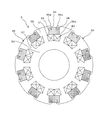
次に、図2及び図3を用いて回転子3の構成について説明する。図2及び図3に示すように、回転子3は、シャフト10に固定された上記回転子鉄心30と、回転子鉄心30に設けられた複数(この例では10個)の上記回転子巻線31及び複数(この例では10個)の永久磁石32とを備えている。なお、回転子巻線31及び永久磁石32の数はこれに限定されるものではない。
次に、図2及び図3を用いて回転子3の構成について説明する。図2及び図3に示すように、回転子3は、シャフト10に固定された上記回転子鉄心30と、回転子鉄心30に設けられた複数(この例では10個)の上記回転子巻線31及び複数(この例では10個)の永久磁石32とを備えている。なお、回転子巻線31及び永久磁石32の数はこれに限定されるものではない。
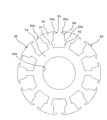
回転子鉄心30は、シャフト10より径方向外側に向けて突出した複数(この例では10個)のティース部35を備える。なお、ティース部35の数はこれに限定されるものではない。より具体的には、回転子鉄心30は、中心に穴部34aを有し当該穴部34aに挿通されたシャフト10に固定される略円筒状の内周部34と、内周部34より径方向外側に向けて突出した上記ティース部35とを備える。回転子鉄心30は、内周部34と複数のティース部35とが一体となった一体構造である。図3に示すように、回転子巻線31及び永久磁石32は、複数のティース部35の相互間において、径方向内側から外側に向けて回転子巻線31、永久磁石32の順で配置されている。
ティース部35は、回転子鉄心30の外周部に配置される磁極部36と、磁極部36と内周部34とを径方向に連結する連結部37とを有する。磁極部36は、この例では軸方向から見て略扇形状を有し、連結部37よりも周方向に太く形成されている。隣り合う磁極部36の相互間には、この例では略矩形状の磁石用空隙38が形成され、永久磁石32はこの磁石用空隙38に収容されて接着等により固定される。磁極部36は、外周部の両側に周方向に突き出したつば部36aを有する。つば部36aは、永久磁石32の外周の一部を覆う。隣り合うティース部35のつば部36a同士は、小間隙39を空けて周方向に対向している。つまり、複数のティース部35は小間隙39の間隔を空けて各々分離されている。
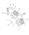
図3に示すように、永久磁石32は周方向に着磁され、周方向両側の2つの磁極部36に固定される。このとき、永久磁石32と磁極部36との間に微小な隙間を設けて例えば接着剤により固定してもよいし、永久磁石32と磁極部36とを直接接触させて接着剤を用いずに固定してもよい。そして、永久磁石32は、外周の一部がつば部36aによって覆われるとともに、小間隙39を介して径方向外方に露出されている。複数の磁石用空隙38に収容された複数の永久磁石32は、周方向に隣り合う永久磁石32同士でS極又はN極の同極の磁極を対向させた態様で、対向する磁極が周方向にS極とN極とを交互に繰り返すように配置されている。
連結部37は、この例では軸方向から見て略長方形状を有し、磁極部36よりも周方向に細く形成されている。隣り合う連結部37相互間には、この例では略扇形状の巻線用空隙40が形成されている。巻線用空隙40は、上記磁石用空隙38と連通されている。すなわち、回転子鉄心30は、磁石用空隙38と巻線用空隙40との間に磁性体が存在しないように構成されている。連結部37には回転子巻線31が巻回される。連結部37に巻回された回転子巻線31は、巻線用空隙40に収容されるとともに、外周の少なくとも一部が磁極部36によって(遠心力に対して)支持されている。言い換えると、連結部37と磁極部36との間にはそれらの太さの相違により段差部35aが形成されており、連結部37に巻回された回転子巻線31は外周の少なくとも一部が段差部35aによって覆われている。
<回転子巻線の通電による界磁磁束の変化>
回転電機1は、回転子3に永久磁石32の他に回転子巻線31を備えるので、回転子巻線31の通電方向及び通電量を変化させることにより界磁磁束を可変させることができる。この詳細について、図4~図6を用いて説明する。
回転電機1は、回転子3に永久磁石32の他に回転子巻線31を備えるので、回転子巻線31の通電方向及び通電量を変化させることにより界磁磁束を可変させることができる。この詳細について、図4~図6を用いて説明する。
図4に、回転子巻線31の無通電時の回転子3の界磁磁束の状態の一例を示す。図4に示すように、磁極部36を挟んで隣り合う2つの永久磁石32のN極から出た磁束のうち一部は、磁極部36から連結部37を経て内周部34を通る漏れ磁束q1となる。その結果、磁極部36から径方向外方へ向かう界磁磁束Qは、中程度の強さとなる。
図5に、界磁磁束を弱める方向に回転子巻線31を通電した際の回転子3の界磁磁束の状態の一例を示す。図5に示すように、回転子巻線31に対し界磁磁束を弱める方向に電流iを流すと、回転子巻線31による磁束q2により、磁極部36から内周部34側への漏れ磁束q1が大きくなる。このときの回転子巻線31による磁束q2の向きは、N極の磁極部36では径方向外側から内側、S極の磁極部36では径方向内側から外側となる。漏れ磁束q1が大きくなった分、界磁磁束Qは図4に示す無通電時より減少する。なお、界磁磁束Qの減少量は回転子巻線31の通電量により制御される。
図6に、界磁磁束を強める方向に回転子巻線31を通電した際の回転子3の界磁磁束の状態の一例を示す。図6に示すように、回転子巻線31に対し界磁磁束を強める方向に電流iを流すと、回転子巻線31による磁束q2により、磁極部36から内周部34側への漏れ磁束q1が減少あるいは消滅する。このときの回転子巻線31による磁束q2の向きは、N極の磁極部36では径方向内側から外側、S極の磁極部36では径方向外側から内側となる。漏れ磁束q1が減少あるいは消滅し、且つ、回転子巻線31による磁束q2が加わった分、界磁磁束Qは図4に示す無通電時より増大する。なお、界磁磁束Qの増大量は回転子巻線31の通電量により制御される。
なお、つば部36aがティース部の相互間に配置された永久磁石をティース部に保持する手段の一例に相当し、段差部35aがティース部に巻回された回転子巻線をティース部に保持する手段の一例に相当する。
<実施形態の効果>
以上説明したように、回転電機1は、シャフト10より径方向外側に向けて突出した複数のティース部35を備えた回転子鉄心30と、複数のティース部35の各々に巻回された回転子巻線31と、複数のティース部35の相互間に配置された複数の永久磁石32と、を有する。そして、回転子巻線31を永久磁石32による磁束を強める方向に通電することで界磁磁束Qを増大させ、回転子巻線31を永久磁石32による磁束を弱める方向に通電することで界磁磁束Qを減少させる。これにより、界磁磁束Qを増大させることで大きなトルクを出すことが可能となり、界磁磁束Qを減少させることで誘起電圧の飽和が抑えられ高速回転化することが可能となる。したがって、大トルク化と高速回転化の両立を図ることができる。
以上説明したように、回転電機1は、シャフト10より径方向外側に向けて突出した複数のティース部35を備えた回転子鉄心30と、複数のティース部35の各々に巻回された回転子巻線31と、複数のティース部35の相互間に配置された複数の永久磁石32と、を有する。そして、回転子巻線31を永久磁石32による磁束を強める方向に通電することで界磁磁束Qを増大させ、回転子巻線31を永久磁石32による磁束を弱める方向に通電することで界磁磁束Qを減少させる。これにより、界磁磁束Qを増大させることで大きなトルクを出すことが可能となり、界磁磁束Qを減少させることで誘起電圧の飽和が抑えられ高速回転化することが可能となる。したがって、大トルク化と高速回転化の両立を図ることができる。
また、本実施形態では特に、複数のティース部35が各々分離されている。これにより、ティース部35相互間で発生する漏れ磁束を低減できる。また、ティース部35相互間の隙間である小間隙39を利用して、回転子巻線31を各ティース部35に対し回転子鉄心20の外周側より巻くことができるので、内周部34と各ティース部35とが一体となった回転子鉄心30を実現できる。
また、本実施形態では特に、回転子巻線31及び永久磁石32は、複数のティース部35の相互間において、径方向内側から外側に向けて回転子巻線31、永久磁石32の順で配置される。これにより、回転子巻線31の外周の少なくとも一部を永久磁石32によって(遠心力に対して)支持することができる。また、回転子巻線31をティース部35に巻回した後に、永久磁石32をティース部35の相互間に挿入する、という製造方法をとることができる。
また、本実施形態では特に、ティース部35は、回転子鉄心30の外周部に配置される磁極部36と、磁極部36とシャフト10に固定される内周部34とを径方向に連結する連結部37と、を有し、永久磁石32は、磁極部36の相互間に配置され、回転子巻線31は、連結部37に巻回される。これにより、次のような効果を奏する。
すなわち、例えば磁極部36の周方向中央部に永久磁石が配置される構成を考えた場合、回転子巻線31の鉄心となる連結部37と固定子2との間に永久磁石が配置されることとなる。この場合、回転子巻線31を永久磁石による磁束を弱める方向に通電した際に永久磁石の減磁を招く可能性がある。これに対し、本実施形態によれば、上記構成により連結部37と固定子2との間に永久磁石32が配置されない構成とすることができるので、永久磁石32の減磁を防止できる。
また、本実施形態では特に、磁極部36は、連結部37よりも周方向に太く形成され、連結部37に巻回された回転子巻線31の外周の少なくとも一部を支持する。これにより、回転子巻線31の外周の少なくとも一部を遠心力に抗して支持することが可能となるので、回転子巻線31を堅固に保持することができる。したがって、回転子巻線31の脱落や変形を防止できる。
また、本実施形態では特に、永久磁石32は、周方向に着磁され、周方向両側の2つの磁極部36に接着により固定される。永久磁石32を周方向に着磁することにより、回転子鉄心30をいわゆるオープンスロット構造(回転子巻線31が収容される巻線用空隙40が回転子鉄心30の外周に開口した構造)とすることができる。また、各永久磁石32が周方向両側の2つの磁極部36に接着により固定されることにより、永久磁石32用の固定部材を別途用意する必要がない。
また、本実施形態では特に、磁極部36は、永久磁石32の外周の一部を覆うつば部36aを周方向両側に有する。このつば部36aにより、永久磁石32の外周の周方向両側部分を遠心力に抗して支持することが可能となるので、永久磁石32を堅固に保持することができる。したがって、永久磁石32の脱落を防止できる。
また、本実施形態では特に、回転子鉄心30は、内周部34とティース部35とが一体となった構造である。これにより、回転子鉄心30の遠心力に対する強度を高めることができる。また、回転子鉄心30の製造工程を簡易化できる。
また、本実施形態では特に、回転子鉄心30は、複数のティース部35の相互間に形成される、永久磁石32が収容される磁石用空隙38と回転子巻線31が収容される巻線用空隙40との間に、磁性体が存在しないように構成される。これにより、ティース部35相互間で発生する漏れ磁束をさらに低減できる。
また、本実施形態では特に、回転電機1は、回転子鉄心30の軸方向端部に接触するようにシャフト10に固定され、回転子巻線31のコイルエンド部31aを収納する溝部19aを備えた固定環部材19を有する。この固定環部材19により、回転子鉄心30の軸方向位置を位置決めできる。また、固定環部材19の溝部19aにより、回転子巻線31のコイルエンド部31aを遠心力に抗して支持することが可能となるので、コイルエンド部31aの変形を防止できる。
<変形例>
なお、開示の実施形態は、上記に限られるものではなく、その趣旨及び技術的思想を逸脱しない範囲内で種々の変形が可能である。
なお、開示の実施形態は、上記に限られるものではなく、その趣旨及び技術的思想を逸脱しない範囲内で種々の変形が可能である。
例えば、回転子巻線31の冷却構造を別途設ける場合には、固定環部材19の所々に冷却媒体を流通させる穴を形成してもよい。
また例えば、回転子巻線31への給電方法は、スリップリング16及びブラシ17を用いるものに限定されるものではなく、他の方法を用いてもよい。例えば、ロータリコネクタを用いて給電する方法でも、トランスにより交流を供給した後に直流に整流して給電する方法でもよい。
また、以上既に述べた以外にも、上記実施形態による手法を適宜組み合わせて利用しても良い。その他、一々例示はしないが、上記実施形態は、その趣旨を逸脱しない範囲内において、種々の変更が加えられて実施されるものである。
1 回転電機
2 固定子
3 回転子
10 シャフト
19 固定環部材
19a 溝部
30 回転子鉄心
31 回転子巻線
31a コイルエンド部
32 永久磁石
34 内周部
35 ティース部
35a 段差部
36 磁極部
36a つば部
37 連結部
38 磁石用空隙
40 巻線用空隙
2 固定子
3 回転子
10 シャフト
19 固定環部材
19a 溝部
30 回転子鉄心
31 回転子巻線
31a コイルエンド部
32 永久磁石
34 内周部
35 ティース部
35a 段差部
36 磁極部
36a つば部
37 連結部
38 磁石用空隙
40 巻線用空隙
Claims (10)
- 固定子及び回転子を備えた回転電機であって、
シャフトより径方向外側に向けて突出した複数のティース部を備えた回転子鉄心と、
前記複数のティース部の各々に巻回された回転子巻線と、
前記複数のティース部の相互間に配置された複数の永久磁石と、
を有することを特徴とする回転電機。 - 前記複数のティース部は、
各々分離されている
ことを特徴とする請求項1に記載の回転電機。 - 前記回転子巻線及び前記永久磁石は、
前記複数のティース部の相互間において、径方向内側から外側に向けて前記回転子巻線、前記永久磁石の順で配置される
ことを特徴とする請求項2に記載の回転電機。 - 前記ティース部は、
前記回転子鉄心の外周部に配置される磁極部と、
前記磁極部と前記シャフトに固定される内周部とを径方向に連結する連結部と、を有し、
前記永久磁石は、
前記磁極部の相互間に配置され、
前記回転子巻線は、
前記連結部に巻回される
ことを特徴とする請求項3に記載の回転電機。 - 前記磁極部は、
前記連結部よりも周方向に太く形成され、前記連結部に巻回された前記回転子巻線の外周の少なくとも一部を支持する
ことを特徴とする請求項4に記載の回転電機。 - 前記永久磁石は、
周方向に着磁され、周方向両側の2つの前記磁極部に固定される
ことを特徴とする請求項4又は5に記載の回転電機。 - 前記磁極部は、
前記永久磁石の外周の一部を覆うつば部を周方向両側に有する
ことを特徴とする請求項6に記載の回転電機。 - 前記回転子鉄心は、
前記内周部と前記ティース部とが一体となった構造である
ことを特徴とする請求項4乃至7のいずれか1項に記載の回転電機。 - 前記回転子鉄心は、
前記複数のティース部の相互間に形成される、前記永久磁石が収容される磁石用空隙と前記回転子巻線が収容される巻線用空隙との間に、磁性体が存在しないように構成される
ことを特徴とする請求項1乃至8のいずれか1項に記載の回転電機。 - 前記回転子鉄心の軸方向端部に接触するように前記シャフトに固定され、前記回転子巻線の前記回転子鉄心より軸方向に突出した部分を収納する溝部を備えた固定環部材をさらに有する
ことを特徴とする請求項1乃至9のいずれか1項に記載の回転電機。
Priority Applications (1)
| Application Number | Priority Date | Filing Date | Title |
|---|---|---|---|
| PCT/JP2014/064001 WO2015181895A1 (ja) | 2014-05-27 | 2014-05-27 | 回転電機 |
Applications Claiming Priority (1)
| Application Number | Priority Date | Filing Date | Title |
|---|---|---|---|
| PCT/JP2014/064001 WO2015181895A1 (ja) | 2014-05-27 | 2014-05-27 | 回転電機 |
Publications (1)
| Publication Number | Publication Date |
|---|---|
| WO2015181895A1 true WO2015181895A1 (ja) | 2015-12-03 |
Family
ID=54698279
Family Applications (1)
| Application Number | Title | Priority Date | Filing Date |
|---|---|---|---|
| PCT/JP2014/064001 Ceased WO2015181895A1 (ja) | 2014-05-27 | 2014-05-27 | 回転電機 |
Country Status (1)
| Country | Link |
|---|---|
| WO (1) | WO2015181895A1 (ja) |
Cited By (3)
| Publication number | Priority date | Publication date | Assignee | Title |
|---|---|---|---|---|
| EP3373426A1 (en) * | 2017-03-06 | 2018-09-12 | Hamilton Sundstrand Corporation | Wound-rotor synchronous machine with permanent magnets |
| PL239128B1 (pl) * | 2020-01-30 | 2021-11-08 | Siec Badawcza Lukasiewicz Instytut Napedow I Masz Elektrycznych Komel | Prądnica synchroniczna ze wzbudzeniem hybrydowym |
| FR3163785A1 (fr) * | 2024-06-25 | 2025-12-26 | Safran Landing Systems | Machine électrique à cales aimantées |
Citations (4)
| Publication number | Priority date | Publication date | Assignee | Title |
|---|---|---|---|---|
| DE4139843C1 (en) * | 1991-12-03 | 1993-06-24 | Albert 7880 Bad Saeckingen De Mutter | Dynamoelectric machine, esp. for car - has salient pole laminated rotor with permanent magnets between poles plus extra slip ring-fed excitation winding |
| EP1209798A1 (en) * | 2000-11-23 | 2002-05-29 | Delphi Technologies, Inc. | Wound salient-pole type rotor for an electric machine |
| JP2008228460A (ja) * | 2007-03-13 | 2008-09-25 | Kanazawa Inst Of Technology | 回転機及び回転機を製造する方法 |
| JP2013009553A (ja) * | 2011-06-27 | 2013-01-10 | Toyota Central R&D Labs Inc | 回転電機のロータ |
-
2014
- 2014-05-27 WO PCT/JP2014/064001 patent/WO2015181895A1/ja not_active Ceased
Patent Citations (4)
| Publication number | Priority date | Publication date | Assignee | Title |
|---|---|---|---|---|
| DE4139843C1 (en) * | 1991-12-03 | 1993-06-24 | Albert 7880 Bad Saeckingen De Mutter | Dynamoelectric machine, esp. for car - has salient pole laminated rotor with permanent magnets between poles plus extra slip ring-fed excitation winding |
| EP1209798A1 (en) * | 2000-11-23 | 2002-05-29 | Delphi Technologies, Inc. | Wound salient-pole type rotor for an electric machine |
| JP2008228460A (ja) * | 2007-03-13 | 2008-09-25 | Kanazawa Inst Of Technology | 回転機及び回転機を製造する方法 |
| JP2013009553A (ja) * | 2011-06-27 | 2013-01-10 | Toyota Central R&D Labs Inc | 回転電機のロータ |
Cited By (4)
| Publication number | Priority date | Publication date | Assignee | Title |
|---|---|---|---|---|
| EP3373426A1 (en) * | 2017-03-06 | 2018-09-12 | Hamilton Sundstrand Corporation | Wound-rotor synchronous machine with permanent magnets |
| PL239128B1 (pl) * | 2020-01-30 | 2021-11-08 | Siec Badawcza Lukasiewicz Instytut Napedow I Masz Elektrycznych Komel | Prądnica synchroniczna ze wzbudzeniem hybrydowym |
| FR3163785A1 (fr) * | 2024-06-25 | 2025-12-26 | Safran Landing Systems | Machine électrique à cales aimantées |
| WO2026003123A1 (fr) * | 2024-06-25 | 2026-01-02 | Safran Landing Systems | Dispositif de freinage a cales aimantees |
Similar Documents
| Publication | Publication Date | Title |
|---|---|---|
| JP5673640B2 (ja) | ハイブリッド励磁式回転電機 | |
| US9124161B2 (en) | Double-stator/double-rotor type motor and direct drive apparatus for washer using same | |
| US8987962B2 (en) | Double-stator/double-rotor type motor and direct drive apparatus for washer using same | |
| JP3205336U (ja) | 単相モータ及びこれを有する電気装置 | |
| CN104953737B (zh) | 一种永磁无刷电机 | |
| JP2016214070A (ja) | 単相モータ及びこれを有する電気装置 | |
| US20230046567A1 (en) | Magnetic geared rotary electric machine | |
| JP6561692B2 (ja) | 回転電機 | |
| KR20140091626A (ko) | 자속 집중형 모터 | |
| WO2007080841A1 (ja) | 電動機及びこれを搭載した機器 | |
| JP2015073355A (ja) | 回転電機の回転子、回転電機、回転電機の着磁装置 | |
| JP2020188612A (ja) | 回転電機 | |
| CN104919686A (zh) | 电机 | |
| WO2015181895A1 (ja) | 回転電機 | |
| JP5869306B2 (ja) | ロータ及びモータ | |
| JP2015119539A (ja) | 車両用ブラシレス交流発電機 | |
| JP2017204961A (ja) | 回転電機 | |
| JP2013005627A (ja) | ロータ及びモータ | |
| JP2010166787A (ja) | 回転電機 | |
| JP2016077130A (ja) | 直流モータ | |
| JP2020137350A (ja) | アキシャルギャップモータ | |
| JP6485046B2 (ja) | 直流モータ | |
| KR20200014040A (ko) | 토크리플 감소를 위한 노치구조의 전동기 | |
| JP2016171660A (ja) | 回転電機のロータ | |
| WO2014188505A1 (ja) | 回転電機 |
Legal Events
| Date | Code | Title | Description |
|---|---|---|---|
| 121 | Ep: the epo has been informed by wipo that ep was designated in this application |
Ref document number: 14892939 Country of ref document: EP Kind code of ref document: A1 |
|
| NENP | Non-entry into the national phase |
Ref country code: DE |
|
| 122 | Ep: pct application non-entry in european phase |
Ref document number: 14892939 Country of ref document: EP Kind code of ref document: A1 |
|
| NENP | Non-entry into the national phase |
Ref country code: JP |