WO2015181881A1 - Diesel engine control device and control method - Google Patents
Diesel engine control device and control method Download PDFInfo
- Publication number
- WO2015181881A1 WO2015181881A1 PCT/JP2014/063949 JP2014063949W WO2015181881A1 WO 2015181881 A1 WO2015181881 A1 WO 2015181881A1 JP 2014063949 W JP2014063949 W JP 2014063949W WO 2015181881 A1 WO2015181881 A1 WO 2015181881A1
- Authority
- WO
- WIPO (PCT)
- Prior art keywords
- injection
- fuel
- diesel engine
- main
- ignition delay
- Prior art date
Links
Images


Classifications
-
- F—MECHANICAL ENGINEERING; LIGHTING; HEATING; WEAPONS; BLASTING
- F02—COMBUSTION ENGINES; HOT-GAS OR COMBUSTION-PRODUCT ENGINE PLANTS
- F02D—CONTROLLING COMBUSTION ENGINES
- F02D41/00—Electrical control of supply of combustible mixture or its constituents
- F02D41/30—Controlling fuel injection
- F02D41/38—Controlling fuel injection of the high pressure type
- F02D41/40—Controlling fuel injection of the high pressure type with means for controlling injection timing or duration
- F02D41/402—Multiple injections
-
- F—MECHANICAL ENGINEERING; LIGHTING; HEATING; WEAPONS; BLASTING
- F02—COMBUSTION ENGINES; HOT-GAS OR COMBUSTION-PRODUCT ENGINE PLANTS
- F02D—CONTROLLING COMBUSTION ENGINES
- F02D41/00—Electrical control of supply of combustible mixture or its constituents
- F02D41/30—Controlling fuel injection
- F02D41/3011—Controlling fuel injection according to or using specific or several modes of combustion
- F02D41/3017—Controlling fuel injection according to or using specific or several modes of combustion characterised by the mode(s) being used
- F02D41/3035—Controlling fuel injection according to or using specific or several modes of combustion characterised by the mode(s) being used a mode being the premixed charge compression-ignition mode
-
- F—MECHANICAL ENGINEERING; LIGHTING; HEATING; WEAPONS; BLASTING
- F02—COMBUSTION ENGINES; HOT-GAS OR COMBUSTION-PRODUCT ENGINE PLANTS
- F02B—INTERNAL-COMBUSTION PISTON ENGINES; COMBUSTION ENGINES IN GENERAL
- F02B17/00—Engines characterised by means for effecting stratification of charge in cylinders
- F02B17/005—Engines characterised by means for effecting stratification of charge in cylinders having direct injection in the combustion chamber
-
- F—MECHANICAL ENGINEERING; LIGHTING; HEATING; WEAPONS; BLASTING
- F02—COMBUSTION ENGINES; HOT-GAS OR COMBUSTION-PRODUCT ENGINE PLANTS
- F02D—CONTROLLING COMBUSTION ENGINES
- F02D35/00—Controlling engines, dependent on conditions exterior or interior to engines, not otherwise provided for
- F02D35/02—Controlling engines, dependent on conditions exterior or interior to engines, not otherwise provided for on interior conditions
- F02D35/028—Controlling engines, dependent on conditions exterior or interior to engines, not otherwise provided for on interior conditions by determining the combustion timing or phasing
-
- F—MECHANICAL ENGINEERING; LIGHTING; HEATING; WEAPONS; BLASTING
- F02—COMBUSTION ENGINES; HOT-GAS OR COMBUSTION-PRODUCT ENGINE PLANTS
- F02D—CONTROLLING COMBUSTION ENGINES
- F02D37/00—Non-electrical conjoint control of two or more functions of engines, not otherwise provided for
- F02D37/02—Non-electrical conjoint control of two or more functions of engines, not otherwise provided for one of the functions being ignition
-
- F—MECHANICAL ENGINEERING; LIGHTING; HEATING; WEAPONS; BLASTING
- F02—COMBUSTION ENGINES; HOT-GAS OR COMBUSTION-PRODUCT ENGINE PLANTS
- F02D—CONTROLLING COMBUSTION ENGINES
- F02D41/00—Electrical control of supply of combustible mixture or its constituents
- F02D41/30—Controlling fuel injection
- F02D41/38—Controlling fuel injection of the high pressure type
- F02D41/40—Controlling fuel injection of the high pressure type with means for controlling injection timing or duration
- F02D41/402—Multiple injections
- F02D41/405—Multiple injections with post injections
-
- F—MECHANICAL ENGINEERING; LIGHTING; HEATING; WEAPONS; BLASTING
- F02—COMBUSTION ENGINES; HOT-GAS OR COMBUSTION-PRODUCT ENGINE PLANTS
- F02D—CONTROLLING COMBUSTION ENGINES
- F02D41/00—Electrical control of supply of combustible mixture or its constituents
- F02D41/30—Controlling fuel injection
- F02D41/38—Controlling fuel injection of the high pressure type
- F02D2041/389—Controlling fuel injection of the high pressure type for injecting directly into the cylinder
-
- F—MECHANICAL ENGINEERING; LIGHTING; HEATING; WEAPONS; BLASTING
- F02—COMBUSTION ENGINES; HOT-GAS OR COMBUSTION-PRODUCT ENGINE PLANTS
- F02D—CONTROLLING COMBUSTION ENGINES
- F02D2200/00—Input parameters for engine control
- F02D2200/02—Input parameters for engine control the parameters being related to the engine
-
- F—MECHANICAL ENGINEERING; LIGHTING; HEATING; WEAPONS; BLASTING
- F02—COMBUSTION ENGINES; HOT-GAS OR COMBUSTION-PRODUCT ENGINE PLANTS
- F02D—CONTROLLING COMBUSTION ENGINES
- F02D2250/00—Engine control related to specific problems or objectives
- F02D2250/38—Control for minimising smoke emissions, e.g. by applying smoke limitations on the fuel injection amount
-
- Y—GENERAL TAGGING OF NEW TECHNOLOGICAL DEVELOPMENTS; GENERAL TAGGING OF CROSS-SECTIONAL TECHNOLOGIES SPANNING OVER SEVERAL SECTIONS OF THE IPC; TECHNICAL SUBJECTS COVERED BY FORMER USPC CROSS-REFERENCE ART COLLECTIONS [XRACs] AND DIGESTS
- Y02—TECHNOLOGIES OR APPLICATIONS FOR MITIGATION OR ADAPTATION AGAINST CLIMATE CHANGE
- Y02T—CLIMATE CHANGE MITIGATION TECHNOLOGIES RELATED TO TRANSPORTATION
- Y02T10/00—Road transport of goods or passengers
- Y02T10/10—Internal combustion engine [ICE] based vehicles
- Y02T10/40—Engine management systems
Definitions
- the present invention relates to a control device and a control method for a direct injection diesel engine that includes a fuel injection nozzle capable of multistage injection and performs after injection immediately after main injection.
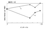
- the cetane number of the fuel is low, as shown in the characteristic b, although there is a tendency for soot to be reduced when the interval is appropriately given, the soot emission is lower than that in the case of not performing after injection.
- the level may be rather high.
- the gas flow in the cavity after ignition increases, and the rising speed of the gas that flows upward from the cavity increases. Therefore, the light spray of after-injection is flowed by the upward flow of gas and taken out to the space below the cylinder head (the space between the cylinder head and the piston crown surface). Since this space is a low-temperature atmosphere field during the expansion stroke, the rate of oxidation of soot due to the fuel of the after-injection and main combustion decreases.
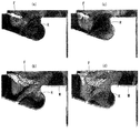
- FIG. 6 shows a state in which the spray by the after injection is affected by the magnitude of the premixed combustion ratio, and shows the gas flow in the combustion chamber with a minute arrow.
- A of the figure shows a state immediately after the after-injection when fuel having a relatively high cetane number is used, and the spray F of the after-injection proceeds toward the inside of the cavity and is ignited at the bottom of the cavity.
- a reverse squish flow R is generated from the inside of the cavity toward the outer peripheral side with combustion.
- B shows a state in which the piston is slightly lowered from the state of (a). Although the spray F collides with the reverse squish flow R, the reverse squish flow is not so strong, so it is taken out upward. (See the area enclosed by an ellipse M).
- (c) and (d) in the figure show the situation at the same crank angle as (a) and (b), respectively, when the cetane number of the fuel is low.
- FIG. 3C when the cetane number is low, the premixed combustion ratio increases with the ignition delay, and thus the reverse squish flow R is strongly generated.
- FIG. 4D the light spray F of the after-injection is taken out upward (see the area surrounded by the ellipse M).
- FIGS. (B) and (d) is the spray dispersed individually.
- JP 2005-233163 A Japanese Patent Laid-Open No. 2000-227061
- the object of the present invention is to avoid soot deterioration due to after-injection when the cetane number of the fuel is low.
- the control device for the diesel engine of the present invention comprises: In a direct injection diesel engine equipped with a fuel injection nozzle capable of multistage injection and performing after injection immediately after main injection, When the premixed combustion ratio in the combustion by the main injection is large, the after injection is prohibited.
- FIG. 1 is an explanatory diagram showing a configuration of a direct injection diesel engine 1 according to the present invention together with its intake and exhaust system.
- a piston 3 is slidably fitted into a cylinder 3 formed in a cylinder block 2.
- the cylinder head 5 fixed to the upper surface of the cylinder block 2 covers the upper end opening of the cylinder 3.
- a reentrant cavity 6 is recessed in the top surface of the piston 4.
- the cavity 6 is formed concentrically with the piston 4 and has a relatively large opening diameter.
- a fuel injection nozzle 7 having multiple injection holes is disposed at the center position of the cylinder 3 corresponding to the center of the cavity 6.
- the fuel injection nozzle 7 is arranged along the central axis of the cylinder 3, that is, vertically.
- the cylinder head 5 is provided with a pair of intake valves 8 and a pair of exhaust valves 9, which open and close the front end openings of the intake port 10 and the exhaust port 11, respectively.
- the intake valve 8 and the exhaust valve 9 are arranged in a vertical posture in which each valve stem is parallel to the central axis of the cylinder 3.
- the cylinder head 5 is provided with a glow plug 12 adjacent to the fuel injection nozzle 7.
- the fuel injection nozzle 7 of each cylinder is connected to a common rail 13 schematically shown.
- a needle (not shown) of the fuel injection nozzle 7 is lifted by a drive signal from the engine control unit 16, the high-pressure fuel pump 14.
- the high-pressure fuel supplied into the common rail 13 is injected.
- the fuel pressure in the common rail 13 is regulated to a predetermined pressure according to the operating conditions by the engine control unit 16 via the pressure regulating valve 15.
- the fuel injection nozzle 7 is a highly responsive one using a piezo element or the like, and has a configuration capable of dividing the total fuel injection amount required according to the load into multiple stages for injection. .
- the diesel engine 1 of this embodiment includes a turbocharger 18, a turbine 19 of the turbocharger 18 is disposed in the passage of the exhaust passage 21, and the compressor 20 is disposed in the passage of the intake passage 22.
- a pre-catalytic converter 23 and a main catalytic converter 24 are arranged in series downstream of the turbine 19 in the exhaust passage 21.
- An air flow meter 25 and an air cleaner 26 are provided on the upstream side of the compressor 20 in the intake passage 22, and an intercooler 27 is disposed between the collector portion 28 on the downstream side of the compressor 20. .
- an exhaust gas recirculation passage 29 that communicates the position of the exhaust passage 21 upstream of the turbine 19 and the intake collector portion 28, and the exhaust gas recirculation rate to a predetermined exhaust gas recirculation rate according to engine operating conditions.
- an exhaust gas recirculation control valve 30 provided for control.
- the engine control unit 16 includes a rotation speed sensor 31 that detects the engine rotation speed Ne, a rail pressure sensor 32 that detects the rail pressure Prail in the common rail 13, and an intake air that detects the intake air temperature Tin. Temperature sensor 33, boost pressure sensor 34 for detecting boost pressure Boost, atmospheric temperature sensor 35 for detecting atmospheric temperature Tatm, atmospheric pressure sensor 36 for detecting atmospheric pressure Patm, water temperature sensor 37 for detecting water temperature Tw, in-cylinder pressure A detection signal from a sensor such as an in-cylinder pressure sensor 38 for detecting Pcyl is input.
- the total injection amount Q to be injected from the fuel injection nozzle 7 is determined according to the load or target torque of the diesel engine 1. Further, the target value of the fuel pressure in the common rail 13, that is, the target rail pressure tPrail is determined based on the total injection amount Q, the rotational speed Ne, the water temperature Tw, the atmospheric pressure Patm, and the atmospheric temperature Tatm. Specifically, a map using the total injection amount Q and the rotational speed Ne as parameters is provided in advance for each water temperature, each atmospheric pressure, and each atmospheric temperature. By searching this map, A target rail pressure tPrail corresponding to the operating condition at that time is determined.
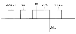
- the fuel injected from the fuel injection nozzle 7 is injected in multiple stages according to the operating conditions. For example, as shown in FIG. 2, in addition to the main injection performed with the top dead center TDC interposed therebetween, the injection is divided into pilot injection, pre-injection, and after-injection. After-injection is mainly for reducing soot generated by combustion by main injection, and after-injection is basically performed in the low-load region and in the medium-high load region except when fully open.
- the injection amount of the main injection and the injection timing of the main injection are expressed in the water temperature Tw, the atmospheric pressure Patm, and the atmospheric temperature Tatm using a map with the total injection amount Q and the rotational speed Ne as parameters.
- a plurality is provided and determined by searching for the corresponding value.
- an interval Int (see FIG. 2) from the end of the main injection to the start of the after injection is also determined based on the total injection amount Q, the rotational speed Ne, the water temperature Tw, the atmospheric pressure Patm, and the atmospheric temperature Tatm.
- the soot generated by the main injection is burned together with the fuel of the after injection, so that the soot can be reduced in the middle and high load range.
- FIG. 3 is a flowchart showing an example of specific processing.
- step 1 it is determined whether or not the operating condition of the diesel engine is in a steady state. If it is not in a steady state, it is difficult to determine whether or not after-injection is appropriate, and therefore the processing after step 2 is not performed.
- after injection itself is also performed at the time of a transition, if it is in a predetermined operating condition range.
- Step 2 If it is steady state, proceed to Step 2 to obtain the ignition delay period of main combustion by main injection.
- the in-cylinder heat generation rate is sequentially obtained based on the detection signal of the in-cylinder pressure sensor 38, and a period until the heat generation rate exceeds a predetermined threshold is detected as an ignition delay period.
- the ignition delay period may be calculated from other parameters without using the in-cylinder pressure sensor 38 that detects the actual combustion state.
- the ignition delay period is calculated from parameters such as the injection amount of the pre-injection, the atmospheric pressure Patm, the boost pressure Boost, the intake air temperature Tin, the rail pressure Prail, the injection timing of the main injection, the rotational speed Ne, and the cetane number of the fuel. Is possible.
- the cetane number of the fuel can be estimated by an appropriate method during operation.
- step 3 it is determined whether or not the ignition delay period is equal to or greater than a predetermined threshold value.
- This threshold value is obtained from a map using the total injection amount Q and the rotational speed Ne as parameters.
- step 4 the process proceeds to step 4 to prohibit after-injection.
- the threshold value As described above, when the cetane number of the fuel is low and the premixed combustion ratio increases with an increase in the ignition delay, the soot is worsened by the after injection. Therefore, when the ignition delay period is equal to or greater than the threshold value, deterioration of soot is avoided by prohibiting after injection.
- step 5 calculates a necessary correction amount for the interval Int from the end of the main injection to the start of after-injection. This can be obtained based on parameters such as the rotational speed Ne, the total injection amount Q, the injection timing of the main injection, the boost pressure Boost, the rail pressure Prail, the atmospheric pressure Patm, and the like.
- step 6 the final interval Int and the after-injection amount are determined.
- FIG. 4 is a flowchart showing another example of specific processing.
- step 11 as in step 1 described above, it is determined whether or not the operating condition of the diesel engine is in a steady state.
- the process proceeds to step 12 to obtain the maximum heat generation rate of main combustion by main injection.
- the in-cylinder heat generation rate is sequentially obtained based on the detection signal of the in-cylinder pressure sensor 38, and the maximum value in the cycle is detected as the maximum heat generation rate.
- the ignition delay period may be calculated from other parameters without using the in-cylinder pressure sensor 38 that detects the actual combustion state. For example, from the parameters such as the pre-injection amount, the atmospheric pressure Patm, the supercharging pressure Boost, the intake air temperature Tin, the rail pressure Prail, the main injection timing, the rotational speed Ne, the fuel cetane number, the main injection amount, etc. It is possible to calculate the delay period.
- step 13 it is determined whether or not the maximum heat generation rate is equal to or greater than a predetermined threshold value.
- This threshold value is obtained from a map using the total injection amount Q and the rotational speed Ne as parameters.
- step 14 If the maximum heat generation rate is greater than or equal to the threshold, the process proceeds to step 14 and after-injection is prohibited.
- the premixed combustion ratio is a rapid combustion is determined based on the maximum heat generation rate. If the premixed combustion ratio is a rapid combustion, the after injection is prohibited. , Avoid soot deterioration.
- step 15 calculates a necessary correction amount for the interval Int from the end of the main injection to the start of after injection. This can be obtained based on parameters such as the rotational speed Ne, the total injection amount Q, the injection timing of the main injection, the boost pressure Boost, the rail pressure Prail, the atmospheric pressure Patm, and the like.
- step 16 the final interval Int and the after-injection amount are determined.
Abstract
Description
多段噴射が可能な燃料噴射ノズルを備え、メイン噴射の直後にアフター噴射を行う直接噴射式ディーゼルエンジンにおいて、
上記メイン噴射による燃焼における予混合燃焼割合が大きいときに、上記アフター噴射を禁止するものである。 The control device for the diesel engine of the present invention comprises:
In a direct injection diesel engine equipped with a fuel injection nozzle capable of multistage injection and performing after injection immediately after main injection,
When the premixed combustion ratio in the combustion by the main injection is large, the after injection is prohibited.
Claims (5)
- 多段噴射が可能な燃料噴射ノズルを備え、メイン噴射の直後にアフター噴射を行う直接噴射式ディーゼルエンジンにおいて、
上記メイン噴射による燃焼における予混合燃焼割合が大きいときに、上記アフター噴射を禁止する、ディーゼルエンジンの制御装置。 In a direct injection diesel engine equipped with a fuel injection nozzle capable of multistage injection and performing after injection immediately after main injection,
A control apparatus for a diesel engine, which prohibits the after injection when the premixed combustion ratio in the combustion by the main injection is large. - 予混合燃焼割合を示すパラメータとしてメイン噴射の着火遅れ期間を検出し、この着火遅れ期間が閾値よりも大きいときに上記アフター噴射を禁止する、請求項1に記載のディーゼルエンジンの制御装置。 The diesel engine control device according to claim 1, wherein an ignition delay period of main injection is detected as a parameter indicating a premixed combustion ratio, and the after injection is prohibited when the ignition delay period is larger than a threshold value.
- 予混合燃焼割合を示すパラメータとしてメイン噴射による燃焼の最大熱発生率を求め、この最大熱発生率が閾値よりも大きいときに上記アフター噴射を禁止する、請求項1に記載のディーゼルエンジンの制御装置。 The diesel engine control device according to claim 1, wherein a maximum heat generation rate of combustion by main injection is obtained as a parameter indicating a premixed combustion ratio, and the after injection is prohibited when the maximum heat generation rate is larger than a threshold value. .
- 燃料のセタン価を用いて上記着火遅れ期間もしくは上記最大熱発生率の算出を行う、請求項2または3に記載のディーゼルエンジンの制御装置。 4. The diesel engine control device according to claim 2, wherein the ignition delay period or the maximum heat generation rate is calculated using a cetane number of fuel.
- 多段噴射が可能な燃料噴射ノズルを備え、メイン噴射の直後にアフター噴射を行う直接噴射式ディーゼルエンジンにおいて、
上記メイン噴射による燃焼における予混合燃焼割合が大きいときに、上記アフター噴射を禁止する、ディーゼルエンジンの制御方法。 In a direct injection diesel engine equipped with a fuel injection nozzle capable of multistage injection and performing after injection immediately after main injection,
A method for controlling a diesel engine, wherein after-injection is prohibited when a premixed combustion ratio in combustion by main injection is large.
Priority Applications (5)
| Application Number | Priority Date | Filing Date | Title |
|---|---|---|---|
| EP14893630.5A EP3150833B1 (en) | 2014-05-27 | 2014-05-27 | Diesel engine control device and control method |
| US15/312,234 US9863361B2 (en) | 2014-05-27 | 2014-05-27 | Diesel engine control device and control method |
| PCT/JP2014/063949 WO2015181881A1 (en) | 2014-05-27 | 2014-05-27 | Diesel engine control device and control method |
| JP2016523002A JP6057022B2 (en) | 2014-05-27 | 2014-05-27 | Diesel engine control device and control method |
| CN201480079236.7A CN106414974B (en) | 2014-05-27 | 2014-05-27 | The control device and control method of diesel engine |
Applications Claiming Priority (1)
| Application Number | Priority Date | Filing Date | Title |
|---|---|---|---|
| PCT/JP2014/063949 WO2015181881A1 (en) | 2014-05-27 | 2014-05-27 | Diesel engine control device and control method |
Publications (1)
| Publication Number | Publication Date |
|---|---|
| WO2015181881A1 true WO2015181881A1 (en) | 2015-12-03 |
Family
ID=54698266
Family Applications (1)
| Application Number | Title | Priority Date | Filing Date |
|---|---|---|---|
| PCT/JP2014/063949 WO2015181881A1 (en) | 2014-05-27 | 2014-05-27 | Diesel engine control device and control method |
Country Status (5)
| Country | Link |
|---|---|
| US (1) | US9863361B2 (en) |
| EP (1) | EP3150833B1 (en) |
| JP (1) | JP6057022B2 (en) |
| CN (1) | CN106414974B (en) |
| WO (1) | WO2015181881A1 (en) |
Families Citing this family (4)
| Publication number | Priority date | Publication date | Assignee | Title |
|---|---|---|---|---|
| CN104712445B (en) * | 2013-12-13 | 2019-09-06 | 周向进 | Single fuel compression ignition with light the method for controlling combustion and internal combustion engine mixed |
| JP6975890B2 (en) * | 2018-04-09 | 2021-12-01 | 株式会社豊田自動織機 | Internal combustion engine control device |
| JP7006497B2 (en) | 2018-05-11 | 2022-02-10 | トヨタ自動車株式会社 | Fuel cell catalyst layer and its manufacturing method |
| CN113123891B (en) * | 2021-06-17 | 2021-08-31 | 潍柴动力股份有限公司 | Control method of combustion system, combustion system and internal combustion engine |
Citations (4)
| Publication number | Priority date | Publication date | Assignee | Title |
|---|---|---|---|---|
| JP2007231790A (en) * | 2006-02-28 | 2007-09-13 | Nissan Motor Co Ltd | Combustion control system of diesel engine |
| JP2009215987A (en) * | 2008-03-11 | 2009-09-24 | Nissan Motor Co Ltd | Control device and fuel property determination device for internal combustion engine |
| JP2010127175A (en) * | 2008-11-27 | 2010-06-10 | Mitsubishi Fuso Truck & Bus Corp | Combustion control device of diesel engine |
| JP2011089445A (en) * | 2009-10-21 | 2011-05-06 | Toyota Motor Corp | Combustion control device of internal combustion engine |
Family Cites Families (12)
| Publication number | Priority date | Publication date | Assignee | Title |
|---|---|---|---|---|
| JP2000227061A (en) | 1999-02-08 | 2000-08-15 | Hino Motors Ltd | Fuel injection device of diesel engine |
| DE10061796A1 (en) * | 2000-12-12 | 2002-07-04 | Man Nutzfahrzeuge Ag | Process for improving the response of turbochargers |
| JP2005048746A (en) * | 2003-07-31 | 2005-02-24 | Nissan Motor Co Ltd | Fuel control device for internal combustion engine |
| US6968830B2 (en) * | 2003-12-30 | 2005-11-29 | General Electric Company | Apparatus and method for suppressing internal combustion ignition engine emissions |
| JP2005233163A (en) | 2004-02-23 | 2005-09-02 | Mitsubishi Motors Corp | Fuel injection control device for diesel engine |
| JP4424242B2 (en) * | 2005-03-30 | 2010-03-03 | トヨタ自動車株式会社 | Mixture state estimation device and emission generation amount estimation device for internal combustion engine |
| US7793638B2 (en) * | 2006-04-20 | 2010-09-14 | Sturman Digital Systems, Llc | Low emission high performance engines, multiple cylinder engines and operating methods |
| US20110067395A1 (en) * | 2009-09-22 | 2011-03-24 | Eaton Corporation | Method of controlling an engine during transient operating conditions |
| EP2587010A1 (en) * | 2010-06-25 | 2013-05-01 | Nissan Motor Co., Ltd | Diesel engine exhaust purification system |
| JP5392293B2 (en) * | 2010-06-29 | 2014-01-22 | マツダ株式会社 | On-vehicle diesel engine and control method of diesel engine |
| JP5482715B2 (en) * | 2010-06-30 | 2014-05-07 | マツダ株式会社 | Diesel engine and control method of diesel engine |
| JP5327267B2 (en) * | 2010-06-30 | 2013-10-30 | マツダ株式会社 | Diesel engine with turbocharger for on-vehicle use and control method for diesel engine |
-
2014
- 2014-05-27 JP JP2016523002A patent/JP6057022B2/en not_active Expired - Fee Related
- 2014-05-27 US US15/312,234 patent/US9863361B2/en active Active
- 2014-05-27 EP EP14893630.5A patent/EP3150833B1/en active Active
- 2014-05-27 WO PCT/JP2014/063949 patent/WO2015181881A1/en active Application Filing
- 2014-05-27 CN CN201480079236.7A patent/CN106414974B/en active Active
Patent Citations (4)
| Publication number | Priority date | Publication date | Assignee | Title |
|---|---|---|---|---|
| JP2007231790A (en) * | 2006-02-28 | 2007-09-13 | Nissan Motor Co Ltd | Combustion control system of diesel engine |
| JP2009215987A (en) * | 2008-03-11 | 2009-09-24 | Nissan Motor Co Ltd | Control device and fuel property determination device for internal combustion engine |
| JP2010127175A (en) * | 2008-11-27 | 2010-06-10 | Mitsubishi Fuso Truck & Bus Corp | Combustion control device of diesel engine |
| JP2011089445A (en) * | 2009-10-21 | 2011-05-06 | Toyota Motor Corp | Combustion control device of internal combustion engine |
Also Published As
| Publication number | Publication date |
|---|---|
| JPWO2015181881A1 (en) | 2017-04-20 |
| EP3150833A4 (en) | 2018-01-31 |
| JP6057022B2 (en) | 2017-01-11 |
| EP3150833B1 (en) | 2019-05-01 |
| US9863361B2 (en) | 2018-01-09 |
| CN106414974A (en) | 2017-02-15 |
| US20170130667A1 (en) | 2017-05-11 |
| EP3150833A1 (en) | 2017-04-05 |
| CN106414974B (en) | 2019-01-11 |
Similar Documents
| Publication | Publication Date | Title |
|---|---|---|
| JP6183552B2 (en) | Diesel engine control device and control method | |
| JP6373777B2 (en) | Combustion control device | |
| JP6467972B2 (en) | Internal combustion engine | |
| EP2511505B1 (en) | Combustion control device | |
| JP6057022B2 (en) | Diesel engine control device and control method | |
| US9957913B2 (en) | Control device for compression-ignited internal combustion engine | |
| US20140366846A1 (en) | Control apparatus for internal combustion engine | |
| JP5233753B2 (en) | Diesel engine control device | |
| JP2017186934A (en) | Combustion control device for diesel engine | |
| JP5158245B1 (en) | Combustion control device | |
| JP7222869B2 (en) | internal combustion engine controller | |
| JP5900626B2 (en) | Diesel engine control device | |
| JP7145044B2 (en) | compression ignition engine | |
| JP2017020399A (en) | Control device for engine | |
| JP6327477B2 (en) | Engine control device | |
| JP5569552B2 (en) | Combustion control device | |
| JP2019183770A (en) | Engine low temperature oxidation reaction detection method and control method, engine low temperature oxidation reaction detection device and control device | |
| JP2008240554A (en) | Fuel injection control device of diesel engine | |
| JP2019138292A (en) | Control device of internal combustion engine |
Legal Events
| Date | Code | Title | Description |
|---|---|---|---|
| 121 | Ep: the epo has been informed by wipo that ep was designated in this application |
Ref document number: 14893630 Country of ref document: EP Kind code of ref document: A1 |
|
| ENP | Entry into the national phase |
Ref document number: 2016523002 Country of ref document: JP Kind code of ref document: A |
|
| WWE | Wipo information: entry into national phase |
Ref document number: 15312234 Country of ref document: US |
|
| NENP | Non-entry into the national phase |
Ref country code: DE |
|
| REEP | Request for entry into the european phase |
Ref document number: 2014893630 Country of ref document: EP |
|
| WWE | Wipo information: entry into national phase |
Ref document number: 2014893630 Country of ref document: EP |