JP5569552B2 - Combustion control device - Google Patents
Combustion control device Download PDFInfo
- Publication number
- JP5569552B2 JP5569552B2 JP2012097836A JP2012097836A JP5569552B2 JP 5569552 B2 JP5569552 B2 JP 5569552B2 JP 2012097836 A JP2012097836 A JP 2012097836A JP 2012097836 A JP2012097836 A JP 2012097836A JP 5569552 B2 JP5569552 B2 JP 5569552B2
- Authority
- JP
- Japan
- Prior art keywords
- fuel injection
- air temperature
- intake air
- temperature
- amount
- Prior art date
- Legal status (The legal status is an assumption and is not a legal conclusion. Google has not performed a legal analysis and makes no representation as to the accuracy of the status listed.)
- Active
Links
- 238000002485 combustion reaction Methods 0.000 title claims description 80
- 239000000446 fuel Substances 0.000 claims description 232
- 238000002347 injection Methods 0.000 claims description 207
- 239000007924 injection Substances 0.000 claims description 207
- 230000006835 compression Effects 0.000 claims description 19
- 238000007906 compression Methods 0.000 claims description 19
- 230000020169 heat generation Effects 0.000 claims description 8
- 230000000979 retarding effect Effects 0.000 claims description 2
- 239000000779 smoke Substances 0.000 description 14
- 238000001514 detection method Methods 0.000 description 10
- 238000000034 method Methods 0.000 description 10
- 230000007423 decrease Effects 0.000 description 7
- 230000003111 delayed effect Effects 0.000 description 6
- 238000010586 diagram Methods 0.000 description 3
- 238000013459 approach Methods 0.000 description 2
- 238000011144 upstream manufacturing Methods 0.000 description 2
- 239000003054 catalyst Substances 0.000 description 1
- 230000006866 deterioration Effects 0.000 description 1
- 238000007599 discharging Methods 0.000 description 1
- 238000004519 manufacturing process Methods 0.000 description 1
- 230000004580 weight loss Effects 0.000 description 1
Images


Classifications
-
- F—MECHANICAL ENGINEERING; LIGHTING; HEATING; WEAPONS; BLASTING
- F02—COMBUSTION ENGINES; HOT-GAS OR COMBUSTION-PRODUCT ENGINE PLANTS
- F02D—CONTROLLING COMBUSTION ENGINES
- F02D41/00—Electrical control of supply of combustible mixture or its constituents
- F02D41/0025—Controlling engines characterised by use of non-liquid fuels, pluralities of fuels, or non-fuel substances added to the combustible mixtures
- F02D41/0047—Controlling exhaust gas recirculation [EGR]
- F02D41/005—Controlling exhaust gas recirculation [EGR] according to engine operating conditions
- F02D41/0057—Specific combustion modes
-
- F—MECHANICAL ENGINEERING; LIGHTING; HEATING; WEAPONS; BLASTING
- F02—COMBUSTION ENGINES; HOT-GAS OR COMBUSTION-PRODUCT ENGINE PLANTS
- F02D—CONTROLLING COMBUSTION ENGINES
- F02D41/00—Electrical control of supply of combustible mixture or its constituents
- F02D41/30—Controlling fuel injection
- F02D41/3011—Controlling fuel injection according to or using specific or several modes of combustion
- F02D41/3017—Controlling fuel injection according to or using specific or several modes of combustion characterised by the mode(s) being used
- F02D41/3035—Controlling fuel injection according to or using specific or several modes of combustion characterised by the mode(s) being used a mode being the premixed charge compression-ignition mode
-
- F—MECHANICAL ENGINEERING; LIGHTING; HEATING; WEAPONS; BLASTING
- F02—COMBUSTION ENGINES; HOT-GAS OR COMBUSTION-PRODUCT ENGINE PLANTS
- F02D—CONTROLLING COMBUSTION ENGINES
- F02D41/00—Electrical control of supply of combustible mixture or its constituents
- F02D41/30—Controlling fuel injection
- F02D41/38—Controlling fuel injection of the high pressure type
- F02D41/40—Controlling fuel injection of the high pressure type with means for controlling injection timing or duration
- F02D41/402—Multiple injections
-
- F—MECHANICAL ENGINEERING; LIGHTING; HEATING; WEAPONS; BLASTING
- F02—COMBUSTION ENGINES; HOT-GAS OR COMBUSTION-PRODUCT ENGINE PLANTS
- F02D—CONTROLLING COMBUSTION ENGINES
- F02D2200/00—Input parameters for engine control
- F02D2200/02—Input parameters for engine control the parameters being related to the engine
- F02D2200/04—Engine intake system parameters
- F02D2200/0414—Air temperature
-
- Y—GENERAL TAGGING OF NEW TECHNOLOGICAL DEVELOPMENTS; GENERAL TAGGING OF CROSS-SECTIONAL TECHNOLOGIES SPANNING OVER SEVERAL SECTIONS OF THE IPC; TECHNICAL SUBJECTS COVERED BY FORMER USPC CROSS-REFERENCE ART COLLECTIONS [XRACs] AND DIGESTS
- Y02—TECHNOLOGIES OR APPLICATIONS FOR MITIGATION OR ADAPTATION AGAINST CLIMATE CHANGE
- Y02T—CLIMATE CHANGE MITIGATION TECHNOLOGIES RELATED TO TRANSPORTATION
- Y02T10/00—Road transport of goods or passengers
- Y02T10/10—Internal combustion engine [ICE] based vehicles
- Y02T10/12—Improving ICE efficiencies
-
- Y—GENERAL TAGGING OF NEW TECHNOLOGICAL DEVELOPMENTS; GENERAL TAGGING OF CROSS-SECTIONAL TECHNOLOGIES SPANNING OVER SEVERAL SECTIONS OF THE IPC; TECHNICAL SUBJECTS COVERED BY FORMER USPC CROSS-REFERENCE ART COLLECTIONS [XRACs] AND DIGESTS
- Y02—TECHNOLOGIES OR APPLICATIONS FOR MITIGATION OR ADAPTATION AGAINST CLIMATE CHANGE
- Y02T—CLIMATE CHANGE MITIGATION TECHNOLOGIES RELATED TO TRANSPORTATION
- Y02T10/00—Road transport of goods or passengers
- Y02T10/10—Internal combustion engine [ICE] based vehicles
- Y02T10/40—Engine management systems
Landscapes
- Engineering & Computer Science (AREA)
- Chemical & Material Sciences (AREA)
- Combustion & Propulsion (AREA)
- Mechanical Engineering (AREA)
- General Engineering & Computer Science (AREA)
- Electrical Control Of Air Or Fuel Supplied To Internal-Combustion Engine (AREA)
- Output Control And Ontrol Of Special Type Engine (AREA)
- Combined Controls Of Internal Combustion Engines (AREA)
Description
本発明は、予混合圧縮着火(PCCI)燃焼を行うエンジンの燃焼制御装置に関するものである。 The present invention relates to a combustion control device for an engine that performs premixed compression ignition (PCCI) combustion.
予混合圧縮着火燃焼を行うエンジンの燃焼制御装置としては、例えば特許文献1に記載されているように、気筒の圧縮行程中期から後期にかけてインジェクタより燃料を複数回に分けて噴射させるものが知られている。
As a combustion control device for an engine that performs premixed compression ignition combustion, for example, as described in
しかしながら、上記従来技術のように、燃料を複数回に分けて噴射させて予混合圧縮着火燃焼を行う場合に、エンジンの燃焼室内に吸入される空気の温度(吸気温度)または外気温度が必要以上に上昇すると、インジェクタより噴射された燃料の着火遅れが短くなる。このため、予混合時間が短くなり、燃料と空気との予混合が不足するため、スモークが発生しやすくなる。 However, when premixed compression ignition combustion is performed by injecting fuel into a plurality of times as in the above prior art, the temperature of the air (intake air temperature) or the outside air temperature taken into the combustion chamber of the engine is more than necessary. When the engine speed rises, the ignition delay of the fuel injected from the injector is shortened. For this reason, the premixing time is shortened and the premixing of fuel and air is insufficient, so that smoke is likely to occur.
本発明の目的は、吸気温度または外気温度が上昇したときに、スモークの発生を抑制することができる燃焼制御装置を提供することである。 The objective of this invention is providing the combustion control apparatus which can suppress generation | occurrence | production of smoke, when intake temperature or outside temperature rises.
本発明は、予混合圧縮着火燃焼を行うエンジンの燃焼制御装置において、エンジンの燃焼室内に燃料を噴射する燃料噴射弁と、予混合圧縮着火燃焼を行うためのメイン燃料噴射を少なくとも2回に分け、熱発生率波形が1回目のメイン燃料噴射及び2回目のメイン燃料噴射に対応して二山形状となるように燃料噴射弁を制御する噴射制御手段と、燃焼室内に対する吸気温度または外気温度を検出する温度検出手段と、エンジンの負荷を検出する負荷検出手段とを備え、噴射制御手段は、負荷検出手段により検出されたエンジンの負荷に基づいて、1回目のメイン燃料噴射及び2回目のメイン燃料噴射を含む少なくとも2回のメイン燃料噴射の燃料噴射量及び燃料噴射時期を決定する決定手段と、温度検出手段により検出された吸気温度または外気温度が所定温度よりも高いときに、吸気温度または外気温度に応じて、決定手段により決定された2回目のメイン燃料噴射の燃料噴射量を減量する噴射量補正手段とを有し、決定手段は、1回目のメイン燃料噴射の燃料噴射量を2回目のメイン燃料噴射よりも多くするように決定することを特徴とするものである。 The present invention relates to an engine combustion control apparatus that performs premixed compression ignition combustion, and at least twice divided a fuel injection valve that injects fuel into the combustion chamber of the engine and a main fuel injection that performs premixed compression ignition combustion. , An injection control means for controlling the fuel injection valve so that the heat generation rate waveform has a two-peak shape corresponding to the first main fuel injection and the second main fuel injection, and the intake air temperature or the outside air temperature for the combustion chamber Temperature detection means for detecting and load detection means for detecting the load of the engine, and the injection control means is configured to perform the first main fuel injection and the second main fuel injection based on the engine load detected by the load detection means. Determining means for determining the fuel injection amount and fuel injection timing of at least two main fuel injections including fuel injection, and the intake air temperature detected by the temperature detecting means or When the outside air temperature is higher than the predetermined temperature, according to the intake air temperature or outside air temperature, it possesses a injection amount correction means for reduction of the fuel injection quantity of the main fuel injection for the second time determined by the determining means, determining means Is characterized in that the fuel injection amount of the first main fuel injection is determined to be larger than that of the second main fuel injection .
このように本発明の燃焼制御装置においては、吸気温度または外気温度が所定温度よりも高いときは、吸気温度または外気温度に応じて2回目のメイン燃料噴射の燃料噴射量を減量することにより、2回目のメイン燃料噴射を実施する時間が短くなるため、燃料噴射終了から燃料着火開始までの予混合時間が長くなり、燃料と空気とが十分に予混合するようになる。これにより、吸気温度または外気温度が必要以上に上昇したときのスモークの発生を抑制することができる。 Thus, in the combustion control device of the present invention, when the intake air temperature or the outside air temperature is higher than the predetermined temperature, the fuel injection amount of the second main fuel injection is reduced according to the intake air temperature or the outside air temperature, Since the time for performing the second main fuel injection is shortened, the premixing time from the end of fuel injection to the start of fuel ignition is lengthened, and the fuel and air are sufficiently premixed. Thereby, it is possible to suppress the occurrence of smoke when the intake air temperature or the outside air temperature rises more than necessary.
好ましくは、噴射量補正手段は、吸気温度または外気温度が所定温度よりも高いときに、吸気温度または外気温度とエンジンの負荷とに応じて、2回目のメイン燃料噴射の燃料噴射量を減量する。この場合には、吸気温度または外気温度とエンジンの負荷と燃料噴射量の減量量との関係に応じた適切な減量量を得ることができる。 Preferably, the injection amount correction means reduces the fuel injection amount of the second main fuel injection according to the intake air temperature or the outside air temperature and the engine load when the intake air temperature or the outside air temperature is higher than a predetermined temperature. . In this case, it is possible to obtain an appropriate amount of reduction corresponding to the relationship between the intake air temperature or outside air temperature, the engine load, and the amount of fuel injection reduction.
また、好ましくは、噴射量補正手段は、2回目のメイン燃料噴射の燃料噴射量を減量した分だけ、決定手段により決定された1回目のメイン燃料噴射の燃料噴射量を増量する。この場合には、1回目及び2回目のメイン燃料噴射の総燃料噴射量が2回目のメイン燃料噴射の燃料噴射量を減量する前と等しくなるため、エンジンの負荷に応じたトルクを出力することができる。 Also, preferably, the injection quantity correction means, by the amount of weight loss of the fuel injection quantity of the second main fuel injection, increasing an amount of fuel injection amount of first main fuel injection determined by the determining means. In this case, since the total fuel injection amount of the first and second main fuel injection becomes equal to the before reduction of fuel injection quantity of the second main fuel injection, to output a torque corresponding to the load of the engine Can do.
さらに、好ましくは、噴射制御手段は、吸気温度または外気温度が所定温度よりも高いときに、吸気温度または外気温度に応じて、決定手段により決定された少なくとも1回目のメイン燃料噴射の燃料噴射時期を遅角する噴射時期補正手段を更に有する。吸気温度または外気温度が必要以上に上昇すると、燃料の着火性が良くなるため着火時期が進角してしまう。そこで、吸気温度または外気温度が所定温度よりも高いときは、吸気温度または外気温度に応じて燃料噴射時期を遅角することにより、燃料の着火時期が遅れるようになる。従って、燃料の着火時期が圧縮上死点よりも更に後の時期となるため、燃焼騒音の増大を抑制することができる。 Further preferably, the injection control means preferably performs fuel injection timing of at least a first main fuel injection determined by the determining means according to the intake air temperature or the outside air temperature when the intake air temperature or the outside air temperature is higher than a predetermined temperature. Further includes an injection timing correction means for retarding. If the intake air temperature or the outside air temperature rises more than necessary, the ignition timing is advanced because the ignitability of the fuel is improved. Therefore, when the intake air temperature or the outside air temperature is higher than a predetermined temperature, the fuel ignition timing is delayed by delaying the fuel injection timing according to the intake air temperature or the outside air temperature. Therefore, since the ignition timing of the fuel is later than the compression top dead center, an increase in combustion noise can be suppressed.
このとき、好ましくは、噴射時期補正手段は、吸気温度または外気温度が所定温度よりも高いときに、吸気温度または外気温度とエンジンの負荷とに応じて、少なくとも1回目のメイン燃料噴射の燃料噴射時期を遅角する。この場合には、吸気温度または外気温度とエンジンの負荷と燃料噴射時期の遅角量との関係に応じた適切な遅角量を得ることができる。 At this time, it is preferable that the injection timing correction unit performs at least the first main fuel injection according to the intake air temperature or the outside air temperature and the engine load when the intake air temperature or the outside air temperature is higher than a predetermined temperature. Delay the time. In this case, it is possible to obtain an appropriate retard amount corresponding to the relationship between the intake air temperature or the outside air temperature, the engine load, and the retard amount of the fuel injection timing.
また、好ましくは、吸気温度または外気温度が所定温度よりも高いときに、燃焼室内の空燃比を大きくするように制御する空燃比制御手段を更に備える。吸気温度または外気温度が必要以上に上昇すると、空気密度が低下するため、空気量が減少する。そこで、吸気温度または外気温度が所定温度よりも高いときは、燃焼室内の空燃比を大きくするように制御することにより、燃焼室内に吸入される空気量が増加するため、スモークの発生を更に抑制することができる。また、未燃分のCOやHCの発生を抑制することもできる。 In addition, it preferably further includes an air-fuel ratio control means for controlling the air-fuel ratio in the combustion chamber to be increased when the intake air temperature or the outside air temperature is higher than a predetermined temperature. When the intake air temperature or the outside air temperature rises more than necessary, the air density decreases, so the amount of air decreases. Therefore, when the intake air temperature or the outside air temperature is higher than the predetermined temperature, the amount of air taken into the combustion chamber increases by controlling the air-fuel ratio in the combustion chamber to be increased, thereby further suppressing the generation of smoke. can do. In addition, generation of unburned CO and HC can be suppressed.
このとき、好ましくは、燃焼室内で燃焼した後の排気ガスの一部を排気再循環ガスとして燃焼室内に還流するための排気再循環通路と、排気再循環通路に設けられ、排気再循環ガスの還流量を調整するバルブ手段とを更に備え、空燃比制御手段は、排気再循環ガスの還流量を減少させるようにバルブ手段を制御する手段である。このように排気再循環ガスの還流量を減少させることにより、簡単に且つ確実に燃焼室内の空燃比を大きくすることができる。 At this time, preferably, an exhaust gas recirculation passage for returning a part of the exhaust gas after combustion in the combustion chamber to the combustion chamber as an exhaust gas recirculation gas and an exhaust gas recirculation passage are provided. And a valve means for adjusting the recirculation amount. The air-fuel ratio control means is a means for controlling the valve means so as to reduce the recirculation amount of the exhaust gas recirculation gas. Thus, by reducing the recirculation amount of the exhaust gas recirculation gas, the air-fuel ratio in the combustion chamber can be easily and reliably increased.
本発明によれば、吸気温度または外気温度が上昇したときに、スモークの発生を抑制することができる。これにより、適切な予混合圧縮着火燃焼を実現することが可能となる。 According to the present invention, it is possible to suppress the occurrence of smoke when the intake air temperature or the outside air temperature rises. As a result, it is possible to realize appropriate premixed compression ignition combustion.
以下、本発明に係わる燃焼制御装置の好適な実施形態について、図面を参照して詳細に説明する。 Hereinafter, a preferred embodiment of a combustion control device according to the present invention will be described in detail with reference to the drawings.
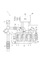
図1は、本発明に係わる燃焼制御装置の一実施形態を備えたディーゼルエンジンを示す概略構成図である。同図において、本実施形態に係わるディーゼルエンジン1は、予混合圧縮着火(PCCI)式の4気筒直列ディーゼルエンジンである。ディーゼルエンジン1はエンジン本体2を備え、このエンジン本体2には4つのシリンダ3が設けられている。
FIG. 1 is a schematic configuration diagram showing a diesel engine equipped with an embodiment of a combustion control device according to the present invention. In the figure, a
各シリンダ3には、燃焼室4内に燃料を噴射するインジェクタ(燃料噴射弁)5がそれぞれ配設されている。インジェクタ5は、噴射ノズル5aから放射状に燃料を噴射する。各インジェクタ5はコモンレール6に接続されており、コモンレール6に貯留された高圧燃料が各インジェクタ5に常時供給されている。
Each
エンジン本体2には、燃焼室4内に空気を吸入するための吸気通路7がインテークマニホールド8を介して接続されている。また、エンジン本体2には、燃焼後の排気ガスを排出するための排気通路9がエキゾーストマニホールド10を介して接続されている。
An
吸気通路7には、上流側から下流側に向けてエアクリーナー11、ターボ過給機12のコンプレッサ13、インタークーラー14及びスロットルバルブ15が設けられている。スロットルバルブ15は、吸気通路7の通路面積を絞り、吸気通路7を通過する空気量を減少させると共に下流側に負圧を発生させる。排気通路9には、上流側から下流側に向けてターボ過給機12のタービン16及び触媒付きDPF17が設けられている。
In the
また、ディーゼルエンジン1は、燃焼後の排気ガスの一部を排気再循環ガス(EGRガス)として燃焼室4内に還流する排気再循環(EGR)ユニット18を備えている。EGRユニット18は、吸気通路7とエキゾーストマニホールド10とを繋ぐように設けられ、EGRガスを還流するためのEGR通路19と、エキゾーストマニホールド10から吸気通路7へのEGRガスの還流量を調整するEGRバルブ(バルブ手段)20と、EGR通路19を通るEGRガスを冷却するEGRクーラ21と、このEGRクーラ21をバイパスするようにEGR通路19に接続されたバイパス通路22と、EGRガスの流路をEGRクーラ21側またはバイパス通路22側に切り替える切替弁23とを有している。
The
上記の各インジェクタ5、スロットルバルブ15、EGRバルブ20及び切替弁23は、電子制御ユニット(ECU)24によって制御される。ECU24には、回転数センサ25、アクセル開度センサ26、吸気温度センサ27が接続されている。
Each
回転数センサ25は、エンジン本体2の回転数(エンジン回転数)を検出するセンサである。回転数センサ25は、例えば図示しないピストンが連結されるクランク軸の回転角度(クランク角)を検出することで、エンジン回転数を検出する。
The
アクセル開度センサ26は、エンジン本体2の負荷(エンジン負荷)の代替値として、アクセルペダルの踏込み角(アクセル開度)を検出するセンサ(負荷検出手段)である。なお、本実施形態のようなコモンレール式燃料噴射装置を備えたディーゼルエンジンでは、燃料噴射量を電子制御しており、エンジン負荷の代替値として燃料噴射量を用いることも可能である。
The
吸気温度センサ27は、燃焼室4内に吸入される空気の温度(燃焼室4内に対する吸気温度)を検出するセンサ(温度検出手段)である。吸気温度センサ27は、例えば吸気通路7におけるEGR通路19との接続部分よりも下流側に取り付けられている。
The intake
ここで、インジェクタ5、EGRユニット18、ECU24及びセンサ25〜27は、本実施形態の燃焼制御装置28を構成している。このような燃焼制御装置28は、吸気行程、圧縮行程、膨張行程及び排気行程という1サイクルにおいて、各インジェクタ5から燃料を2回に分けて噴射する2分割噴射の予混合圧縮着火燃焼を行うように制御する。
Here, the
ECU24は、図2に示すように、インジェクタ制御部29とEGR制御部30とを有している。インジェクタ制御部29は、回転数センサ25、アクセル開度センサ26及び吸気温度センサ27の検出信号を入力し、所定の処理を行い、各インジェクタ5を制御する。EGR制御部30は、アクセル開度センサ26及び吸気温度センサ27の検出信号を入力し、所定の処理を行い、EGRバルブ20を制御する。
As shown in FIG. 2, the
図3は、インジェクタ制御部29により実行される制御処理手順の詳細を示すフローチャートである。同図において、まず回転数センサ25により検出されたエンジン回転数とアクセル開度センサ26により検出されたエンジン負荷とを取得する(手順S101)。そして、エンジン回転数及びエンジン負荷に基づいて、1回目及び2回目の燃料噴射の燃料噴射量及び燃料噴射時期を決定する(手順S102)。このとき、1回目の燃料噴射の燃料噴射量を2回目の燃料噴射の燃料噴射量よりも多くする。
FIG. 3 is a flowchart showing details of a control processing procedure executed by the
続いて、吸気温度センサ27により検出された吸気温度を取得する(手順S103)。そして、吸気温度が基準温度(例えば25℃)よりも高いかどうかを判断する(手順S104)。吸気温度が基準温度よりも高いと判断されたときは、図4に示すような燃料噴射量減量マップを用いて、吸気温度及びエンジン負荷に応じて、手順S102で決定された2回目の燃料噴射の燃料噴射量を減量する(手順S105)。
Subsequently, the intake air temperature detected by the intake
燃料噴射量減量マップは、吸気温度偏差(=吸気温度−基準温度)とエンジン負荷と2回目の燃料噴射の燃料噴射量の減量量との関係を表すマップであり、インジェクタ制御部29のメモリ(図示せず)に予め記憶されている。燃料噴射量減量マップは、吸気温度偏差が所定値A以下のときは、減量量が0であり、吸気温度偏差が所定値Aよりも大きいときは、減量量が吸気温度偏差に従って多くなるように設定されている。また、燃料噴射量減量マップは、エンジン負荷が高くなるほど、減量量が多くなるように設定されている。 The fuel injection amount reduction map is a map showing the relationship between the intake air temperature deviation (= intake air temperature−reference temperature), the engine load, and the reduction amount of the fuel injection amount of the second fuel injection. (Not shown). The fuel injection amount reduction map is such that when the intake air temperature deviation is less than or equal to a predetermined value A, the reduction amount is 0, and when the intake air temperature deviation is greater than the predetermined value A, the reduction amount increases according to the intake air temperature deviation. Is set. Further, the fuel injection amount reduction map is set such that the amount of reduction increases as the engine load increases.
ここで、手順S102で設定される2回目の燃料噴射の燃料噴射量は、図5(a)に示すように、エンジン負荷に従って多くなり、エンジン負荷がある値を超えると一定になる。これに伴って、2回目の燃料噴射の燃料噴射量の減量量は、図5(b)に示すように、エンジン負荷に従って多くなり、エンジン負荷がある値を超えるとほぼ一定になる。このとき、エンジン負荷が低い領域では、圧縮端温度(ピストン圧縮上死点での温度)が低いため、吸気温度が高くなっても、スモーク発生等の影響は少ない。従って、エンジン負荷が所定値Bよりも高くなったときに、2回目の燃料噴射の燃料噴射量の減量を開始する。 Here, as shown in FIG. 5A, the fuel injection amount of the second fuel injection set in step S102 increases according to the engine load, and becomes constant when the engine load exceeds a certain value. Along with this, as shown in FIG. 5B, the amount of decrease in the fuel injection amount of the second fuel injection increases according to the engine load, and becomes substantially constant when the engine load exceeds a certain value. At this time, in the region where the engine load is low, the compression end temperature (temperature at the piston compression top dead center) is low, so that the influence of smoke generation or the like is small even if the intake air temperature increases. Therefore, when the engine load becomes higher than the predetermined value B, the reduction of the fuel injection amount of the second fuel injection is started.
続いて、2回目の燃料噴射の燃料噴射量の減量分だけ1回目の燃料噴射の燃料噴射量を増量する(手順S106)。これにより、1回目及び2回目の燃料噴射の総燃料噴射量が手順S102で設定された総燃料噴射量と同量となるため、エンジン回転数及びエンジン負荷に応じたエンジントルクを出力することができる。 Subsequently, the fuel injection amount of the first fuel injection is increased by an amount corresponding to the reduction of the fuel injection amount of the second fuel injection (step S106). As a result, the total fuel injection amount of the first and second fuel injections is the same as the total fuel injection amount set in step S102, so that engine torque corresponding to the engine speed and engine load can be output. it can.
続いて、予め設定された燃料噴射時期遅角マップ(図示せず)を用いて、吸気温度及びエンジン負荷に応じて、手順S102で決定された1回目及び2回目の燃料噴射の燃料噴射時期を遅角する(手順S107)。 Subsequently, the fuel injection timings of the first and second fuel injections determined in step S102 are determined according to the intake air temperature and the engine load using a preset fuel injection timing delay map (not shown). The angle is retarded (step S107).
燃料噴射時期遅角マップは、吸気温度偏差とエンジン負荷と1回目及び2回目の燃料噴射の燃料噴射時期の遅角量との関係を表すマップである。燃料噴射時期遅角マップは、燃料噴射の燃料噴射時期の遅角量が吸気温度偏差及びエンジン負荷に従って多くなるように設定されている。 The fuel injection timing retard map is a map that represents the relationship between the intake air temperature deviation, the engine load, and the retard amount of the fuel injection timing of the first and second fuel injections. The fuel injection timing retardation map is set so that the amount of retardation of the fuel injection timing of fuel injection increases according to the intake air temperature deviation and the engine load.
ここで、燃料噴射の燃料噴射時期の遅角量は、図6に示すように、エンジン負荷に従って多くなる。このとき、エンジン負荷が低い領域では、2回目の燃料噴射の燃料噴射量を減量していない(図5(b)参照)ため、1回目の燃料噴射の燃料噴射量の増量による燃焼騒音の増大が発生することは無い。従って、エンジン負荷が低い領域では、吸気温度の上昇に伴う燃焼騒音の増大に対してのみ燃料噴射時期を遅角する。 Here, the amount of retardation of the fuel injection timing of the fuel injection increases according to the engine load, as shown in FIG. At this time, in the region where the engine load is low, the fuel injection amount of the second fuel injection is not reduced (see FIG. 5B), and therefore the combustion noise increases due to the increase of the fuel injection amount of the first fuel injection. Will not occur. Therefore, in a region where the engine load is low, the fuel injection timing is retarded only with respect to an increase in combustion noise accompanying an increase in intake air temperature.
手順S107が実行された後、手順S105〜S107で補正された1回目及び2回目の燃料噴射の燃料噴射量及び燃料噴射時期に従って、1回目及び2回目の燃料噴射を順次実施するように各インジェクタ5を制御する(手順S108)。 After step S107 is executed, the injectors are configured to sequentially perform the first and second fuel injections according to the fuel injection amounts and fuel injection timings of the first and second fuel injections corrected in steps S105 to S107. 5 is controlled (step S108).
一方、手順S104で吸気温度が基準温度よりも高くないと判断されたときは、手順S102で決定された1回目及び2回目の燃料噴射の燃料噴射量及び燃料噴射時期に従って、1回目及び2回目の燃料噴射を順次実施するように各インジェクタ5を制御する(手順S108)。
On the other hand, when it is determined in step S104 that the intake air temperature is not higher than the reference temperature, the first and second times according to the fuel injection amount and fuel injection timing of the first and second fuel injections determined in step S102. The
図7は、EGR制御部30により実行される制御処理手順の詳細を示すフローチャートである。同図において、まずアクセル開度センサ26により検出されたエンジン負荷を取得する(手順S111)。そして、エンジン負荷に基づいて、EGRバルブ20の基準となる開度(基準EGRバルブ開度)を決定する(手順S112)。続いて、吸気温度センサ27により検出された吸気温度を取得し(手順S113)、吸気温度が基準温度よりも高いかどうかを判断する(手順S114)。
FIG. 7 is a flowchart showing details of a control processing procedure executed by the
吸気温度が基準温度よりも高いと判断されたときは、燃焼室4内の空燃比(A/F)が大きくなるように基準EGRバルブ開度を補正して、補正EGRバルブ開度を得る(手順S115)。具体的には、EGR率(EGRガスの還流率)が低くなることで燃焼室4内の空燃比が大きくなるように、基準EGRバルブ開度を補正する。このとき、燃焼室4内の空燃比を基準温度時の空燃比と同等とするのが望ましい。続いて、補正EGRバルブ開度となるようにEGRバルブ20を制御する(手順S116)。
When it is determined that the intake air temperature is higher than the reference temperature, the reference EGR valve opening is corrected so as to increase the air-fuel ratio (A / F) in the
一方、手順S114で吸気温度が基準温度よりも高くないと判断されたときは、基準EGRバルブ開度となるようにEGRバルブ20を制御する(手順S116)。
On the other hand, when it is determined in step S114 that the intake air temperature is not higher than the reference temperature, the
以上において、インジェクタ制御部29は、燃料を少なくとも2回に分けて噴射させるように燃料噴射弁5を制御する噴射制御手段を構成する。このとき、インジェクタ制御部29の上記手順S101,S102は、負荷検出手段26により検出されたエンジン1の負荷に基づいて、少なくとも2回の燃料噴射の燃料噴射量及び燃料噴射時期を決定する決定手段として機能する。同手順S103〜106は、温度検出手段27により検出された吸気温度または外気温度が所定温度よりも高いときに、吸気温度または外気温度に応じて、決定手段により決定された2回目の燃料噴射の燃料噴射量を減量する噴射量補正手段として機能する。同手順S103,S104,S107は、吸気温度または外気温度が所定温度よりも高いときに、吸気温度または外気温度に応じて、決定手段により決定された少なくとも1回目の燃料噴射の燃料噴射時期を遅角する噴射時期補正手段を構成する。
In the above, the
また、EGR制御部30は、吸気温度または外気温度が所定温度よりも高いときに、燃焼室4内の空燃比を大きくするように制御する空燃比制御手段を構成する。
Further, the
ところで、吸気温度が基準温度よりも高くなると、2回目の燃料噴射による燃料の着火遅れが短縮されるため、2回目の燃料噴射の終了から当該燃料の着火開始までの予混合時間が短くなり、燃料と空気との予混合の不足によりスモークが発生しやすくなる。また、吸気温度が基準温度よりも高くなると、燃焼室4内に吸入される空気が膨張するため、空気密度が低下し、燃焼室4内に吸入される空気量が減少する。このため、スモークが一層発生しやすくなると共に、未燃分のCOやHCが増加する。さらに、吸気温度が基準温度よりも高くなると、燃料の着火性が高くなるため、燃料の着火時期が進角してピストン圧縮上死点に近くなり、燃焼騒音の増大につながる。
By the way, when the intake air temperature becomes higher than the reference temperature, the delay in fuel ignition due to the second fuel injection is shortened, so the premixing time from the end of the second fuel injection to the start of ignition of the fuel is shortened, Smoke is likely to occur due to insufficient premixing of fuel and air. Further, when the intake air temperature becomes higher than the reference temperature, the air sucked into the
これに対し本実施形態では、吸気温度が基準温度よりも高いときには、吸気温度及びエンジン負荷に応じて2回目の燃料噴射の燃料噴射量を減量するようにしたので、2回目の燃料噴射の実施時間が短くなる。従って、2回目の燃料噴射の終了から当該燃料の着火開始までの予混合時間が長くなり、燃料と空気との予混合が十分に行われる。また、吸気温度が基準温度よりも高いときには、EGR率を低くして燃焼室4内の空燃比を大きくするので、燃焼室4内に吸入される空気量が増加する。以上により、スモークの発生を抑制することができる。また、燃焼室4内に吸入される空気量が増えるため、未燃分のCOやHCを低減することもできる。
In contrast, in the present embodiment, when the intake air temperature is higher than the reference temperature, the fuel injection amount of the second fuel injection is reduced according to the intake air temperature and the engine load. Time is shortened. Therefore, the premixing time from the end of the second fuel injection to the start of ignition of the fuel becomes long, and the fuel and air are sufficiently premixed. Further, when the intake air temperature is higher than the reference temperature, the EGR rate is lowered and the air-fuel ratio in the
さらに、吸気温度が基準温度よりも高いときには、吸気温度及びエンジン負荷に応じて1回目及び2回目の燃料噴射の燃料噴射時期を遅角するので、1回目及び2回目の燃料噴射による燃料の着火時期が遅れるようになる。従って、1回目の燃料噴射による燃料の着火時期を基準温度時とほぼ同じ時期に合わせることができる。これにより、燃焼騒音の増大を防ぐことができる。 Further, when the intake air temperature is higher than the reference temperature, the fuel injection timing of the first and second fuel injections is retarded according to the intake air temperature and the engine load, so that the ignition of fuel by the first and second fuel injections is delayed. The time will be delayed. Therefore, the ignition timing of the fuel by the first fuel injection can be adjusted to substantially the same timing as that at the reference temperature. Thereby, increase of combustion noise can be prevented.
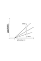
図8は、異なる条件での熱発生率を比較して示したグラフである。図8において、破線Pは、吸気温度が基準温度(ここでは25℃)であるときの熱発生率を示し、1点鎖線Qは、吸気温度が基準温度よりも20℃高いときの熱発生率を示し、実線Rは、吸気温度が基準温度よりも20℃高いときに、2回目の燃料噴射の燃料噴射量を減量し、1回目及び2回目の燃料噴射の燃料噴射時期を遅角し、燃焼室内の空燃比を大きくするという補正を行った場合の熱発生率を示している。 FIG. 8 is a graph showing a comparison of heat generation rates under different conditions. In FIG. 8, the broken line P indicates the heat generation rate when the intake air temperature is the reference temperature (here, 25 ° C.), and the one-dot chain line Q indicates the heat generation rate when the intake air temperature is 20 ° C. higher than the reference temperature. A solid line R indicates that when the intake air temperature is 20 ° C. higher than the reference temperature, the fuel injection amount of the second fuel injection is reduced, and the fuel injection timings of the first and second fuel injections are retarded, It shows the heat generation rate when correction is made to increase the air-fuel ratio in the combustion chamber.
吸気温度が基準温度よりも20℃高いときには、燃料の着火性が向上するため、吸気温度が基準温度であるときに比べて、燃料の着火時期が進角している。しかし、吸気温度が基準温度よりも20℃高いときに上記の補正を行った場合には、1回目及び2回目の燃料噴射の燃料噴射時期が遅角するようになる。このため、その時の1回目の燃料噴射による燃料の着火時期は、吸気温度が基準温度であるときの着火時期にほぼ合うようになる。従って、吸気温度が基準温度よりも20℃高いときに上記の補正を行った場合の熱発生率波形は、吸気温度が基準温度であるときの熱発生率波形に近づくようになる。 When the intake air temperature is 20 ° C. higher than the reference temperature, the ignitability of the fuel is improved. Therefore, the ignition timing of the fuel is advanced compared to when the intake air temperature is the reference temperature. However, when the above correction is performed when the intake air temperature is 20 ° C. higher than the reference temperature, the fuel injection timings of the first and second fuel injections are retarded. For this reason, the ignition timing of the fuel by the first fuel injection at that time almost coincides with the ignition timing when the intake air temperature is the reference temperature. Therefore, the heat generation rate waveform when the above correction is performed when the intake air temperature is 20 ° C. higher than the reference temperature approaches the heat generation rate waveform when the intake air temperature is the reference temperature.
また、吸気温度が基準温度よりも20℃高いときに上記の補正を行った場合には、2回目の燃料噴射の燃料噴射量を減量し、その分だけ1回目の燃料噴射の燃料噴射量を増量する。このため、吸気温度が基準温度よりも20℃高いときに上記の補正を行った場合の熱発生率波形において、2回目の燃料噴射に対応する2つ目の山の高さが僅かに低くなり、1回目の燃料噴射に対応する1つ目の山の高さが僅かに高くなっている。 Further, when the above correction is performed when the intake air temperature is 20 ° C. higher than the reference temperature, the fuel injection amount of the second fuel injection is reduced, and the fuel injection amount of the first fuel injection is reduced by that amount. Increase the amount. For this reason, in the heat release rate waveform when the above correction is performed when the intake air temperature is 20 ° C. higher than the reference temperature, the height of the second peak corresponding to the second fuel injection becomes slightly lower. The height of the first peak corresponding to the first fuel injection is slightly higher.
図9(a)〜(c)は、吸気温度が基準温度であるときと、吸気温度が基準温度よりも20℃高いときと、吸気温度が基準温度よりも20℃高いときに上記の補正を行った場合とで、2回目の燃料噴射による予混合時間、スモーク発生率、燃焼騒音をそれぞれ比較して示したグラフである。 9A to 9C show the above correction when the intake air temperature is the reference temperature, when the intake air temperature is 20 ° C. higher than the reference temperature, and when the intake air temperature is 20 ° C. higher than the reference temperature. It is the graph which compared and showed the case where it performed, and the premix time by the 2nd fuel injection, the smoke generation rate, and the combustion noise, respectively.
図9(a),(b)から分かるように、吸気温度が基準温度よりも20℃高いときには、2回目の燃料噴射による燃料の着火遅れが短縮されるため、吸気温度が基準温度であるときに比べて、予混合時間が短くなり、スモーク発生率が高くなる。しかし、吸気温度が基準温度よりも20℃高いときに上記の補正を行った場合には、2回目の燃料噴射の燃料噴射量が減量されるので、上記の補正を行わない場合に比べて、2回目の燃料噴射による予混合時間が長くなり、スモーク発生率が低くなる。 As can be seen from FIGS. 9 (a) and 9 (b), when the intake air temperature is 20 ° C. higher than the reference temperature, the ignition delay of the fuel due to the second fuel injection is shortened, so the intake air temperature is the reference temperature. As compared with, the premixing time is shortened and the smoke generation rate is increased. However, when the above correction is performed when the intake air temperature is 20 ° C. higher than the reference temperature, the fuel injection amount of the second fuel injection is reduced. Therefore, compared to the case where the above correction is not performed, The premixing time by the second fuel injection becomes longer, and the smoke generation rate becomes lower.
また、図9(c)から分かるように、吸気温度が基準温度よりも20℃高いときには、燃料の着火時期が進角するため、吸気温度が基準温度であるときに比べて燃焼騒音が増大する。しかし、吸気温度が基準温度よりも20℃高いときに上記の補正を行った場合には、1回目及び2回目の燃料噴射の燃料噴射時期が遅角される。このため、その時の1回目の燃料噴射による燃料の着火時期が、吸気温度が基準温度であるときの着火時期にほぼ合うようになるため、上記の補正を行わない場合に比べて燃焼騒音が低減される。 Further, as can be seen from FIG. 9C, when the intake air temperature is 20 ° C. higher than the reference temperature, the ignition timing of the fuel advances, so that the combustion noise increases compared to when the intake air temperature is the reference temperature. . However, when the above correction is performed when the intake air temperature is 20 ° C. higher than the reference temperature, the fuel injection timings of the first and second fuel injections are retarded. For this reason, since the ignition timing of the fuel by the first fuel injection at that time almost matches the ignition timing when the intake air temperature is the reference temperature, the combustion noise is reduced as compared with the case where the above correction is not performed. Is done.
以上のように本実施形態によれば、吸気温度が上昇した場合でも、基準温度時とほぼ同様のPCCI燃焼を実現し、燃焼騒音の増大やエミッションの悪化を抑制することが可能となる。 As described above, according to the present embodiment, even when the intake air temperature rises, PCCI combustion that is substantially the same as that at the reference temperature can be realized, and an increase in combustion noise and a deterioration in emissions can be suppressed.
なお、本発明は、上記実施形態に限定されるものではない。例えば上記実施形態では、吸気温度を検出する吸気温度センサ27を設けたが、吸気温度センサ27の代わりに、外気温度を検出する外気温度センサを設け、外気温度とEGR率とに基づいて吸気温度の上昇量を推定しても良い。この場合、外気温度センサは、例えばエアクリーナー11に設けられる。また、EGR率は、ECU24によって計算される。
The present invention is not limited to the above embodiment. For example, in the above-described embodiment, the intake
また、上記実施形態では、吸気温度が基準温度よりも高いときには、1回目及び2回目の燃料噴射の燃料噴射時期をいずれも遅角するようにしたが、2回目の燃料噴射による燃料の着火時期を、吸気温度が基準温度であるときの着火時期に合わせるためには、2回目の燃料噴射の燃料噴射時期については、特に変更しなくても良いし、或いは逆に進角させても良い。 In the above embodiment, when the intake air temperature is higher than the reference temperature, the fuel injection timings of the first and second fuel injections are both retarded. However, the fuel ignition timing by the second fuel injection is delayed. To match the ignition timing when the intake air temperature is the reference temperature, the fuel injection timing of the second fuel injection need not be changed, or may be advanced.
さらに、上記実施形態では、吸気温度及びエンジン負荷に応じて、2回目の燃料噴射の燃料噴射量の減量量を特定するようにしたが、2回目の燃料噴射の燃料噴射量の減量量を、吸気温度または外気温度のみに応じて特定しても良い。この場合であっても、2回目の燃料噴射の実施時間が短くなり、予混合時間が長くなるため、スモークの発生を抑制することができる。 Furthermore, in the above-described embodiment, the amount of decrease in the fuel injection amount of the second fuel injection is specified according to the intake air temperature and the engine load. You may specify only according to intake temperature or outside temperature. Even in this case, since the time for performing the second fuel injection is shortened and the premixing time is lengthened, the occurrence of smoke can be suppressed.
また、上記実施形態では、吸気温度及びエンジン負荷に応じて、1回目及び2回目の燃料噴射の燃料噴射時期を遅角するようにしたが、吸気温度または外気温度のみに応じて、少なくとも1回目の燃料噴射の燃料噴射時期を遅角するようにしても良い。この場合であっても、1回目の燃料噴射による燃料の着火時期を基準温度時とほぼ同じ時期に合わせることができ、燃焼騒音の増大を防ぐことができる。 In the above embodiment, the fuel injection timings of the first and second fuel injections are delayed according to the intake air temperature and the engine load, but at least the first time according to only the intake air temperature or the outside air temperature. The fuel injection timing of this fuel injection may be retarded. Even in this case, the ignition timing of the fuel by the first fuel injection can be adjusted to substantially the same timing as the reference temperature, and an increase in combustion noise can be prevented.
さらに、上記実施形態では、EGRバルブ20によりEGRガスの流量を調整することで、燃焼室4内の空燃比を制御するようにしたが、空燃比の制御方法としては特にそれには限られず、例えばターボ過給機12の過給圧を調整しても良い。この場合、燃焼室4内の空燃比を大きくするには、ターボ過給機12の過給圧を上げるようにする。
Furthermore, in the above embodiment, the air-fuel ratio in the
また、上記実施形態では、2分割噴射の予混合圧縮着火燃焼を行うものとしたが、燃料を3回以上に分けて噴射する予混合圧縮着火燃焼を行っても良い。この場合でも、吸気温度が基準温度よりも高いときには、2回目の燃料噴射の燃料噴射量を減量する。また、予混合圧縮着火燃焼を行う分割噴射(メイン噴射)の前に少量のプレ噴射を行ったり、分割噴射の後に少量のアフター噴射を行っても良い。 In the above-described embodiment, the premixed compression ignition combustion of the two-split injection is performed. However, the premixed compression ignition combustion in which the fuel is injected in three or more times may be performed. Even in this case, when the intake air temperature is higher than the reference temperature, the fuel injection amount of the second fuel injection is reduced. Further, a small amount of pre-injection may be performed before split injection (main injection) for performing premixed compression ignition combustion, or a small amount of after-injection may be performed after split injection.
1…ディーゼルエンジン、4…燃焼室、5…インジェクタ(燃料噴射弁)、19…EGR通路(排気再循環通路)、20…EGRバルブ(バルブ手段)、24…ECU、26…アクセル開度センサ(負荷検出手段)、27…吸気温度センサ(温度検出手段)、28…燃焼制御装置、29…インジェクタ制御部(噴射制御手段、決定手段、噴射量補正手段、噴射時期補正手段)、30…EGR制御部(空燃比制御手段)。
DESCRIPTION OF
Claims (7)
前記エンジンの燃焼室内に燃料を噴射する燃料噴射弁と、
前記予混合圧縮着火燃焼を行うためのメイン燃料噴射を少なくとも2回に分け、熱発生率波形が1回目のメイン燃料噴射及び2回目のメイン燃料噴射に対応して二山形状となるように前記燃料噴射弁を制御する噴射制御手段と、
前記燃焼室内に対する吸気温度または外気温度を検出する温度検出手段と、
前記エンジンの負荷を検出する負荷検出手段とを備え、
前記噴射制御手段は、前記負荷検出手段により検出された前記エンジンの負荷に基づいて、前記1回目のメイン燃料噴射及び前記2回目のメイン燃料噴射を含む前記少なくとも2回のメイン燃料噴射の燃料噴射量及び燃料噴射時期を決定する決定手段と、前記温度検出手段により検出された前記吸気温度または前記外気温度が所定温度よりも高いときに、前記吸気温度または前記外気温度に応じて、前記決定手段により決定された前記2回目のメイン燃料噴射の燃料噴射量を減量する噴射量補正手段とを有し、
前記決定手段は、前記1回目のメイン燃料噴射の燃料噴射量を前記2回目のメイン燃料噴射よりも多くするように決定することを特徴とする燃焼制御装置。 In an engine combustion control device that performs premixed compression ignition combustion,
A fuel injection valve for injecting fuel into the combustion chamber of the engine;
The main fuel injection for performing the premixed compression ignition combustion is divided into at least two times, and the heat generation rate waveform is formed in a double shape corresponding to the first main fuel injection and the second main fuel injection. Injection control means for controlling the fuel injection valve;
Temperature detecting means for detecting an intake air temperature or an outside air temperature with respect to the combustion chamber;
Load detecting means for detecting the load of the engine,
Said injection control means based on the load of the engine detected by the load detecting means, said first main fuel injection and the said at least two main fuel injection of the fuel injection, including a second main fuel injection Determining means for determining the amount and fuel injection timing; and when the intake air temperature or the outside air temperature detected by the temperature detecting means is higher than a predetermined temperature, the determining means according to the intake air temperature or the outside air temperature It possesses the injection quantity correction means for reduction of the fuel injection amount of the determined said second main fuel injection by,
The determination means determines the fuel injection amount of the first main fuel injection to be larger than that of the second main fuel injection .
前記排気再循環通路に設けられ、前記排気再循環ガスの還流量を調整するバルブ手段とを更に備え、
前記空燃比制御手段は、前記排気再循環ガスの還流量を減少させるように前記バルブ手段を制御する手段であることを特徴とする請求項6記載の燃焼制御装置。 An exhaust gas recirculation passage for returning a part of the exhaust gas after combustion in the combustion chamber as an exhaust gas recirculation gas into the combustion chamber;
Valve means for adjusting a recirculation amount of the exhaust gas recirculation gas provided in the exhaust gas recirculation passage;
7. The combustion control apparatus according to claim 6, wherein the air-fuel ratio control means is means for controlling the valve means so as to reduce the recirculation amount of the exhaust gas recirculation gas.
Priority Applications (2)
| Application Number | Priority Date | Filing Date | Title |
|---|---|---|---|
| JP2012097836A JP5569552B2 (en) | 2012-04-23 | 2012-04-23 | Combustion control device |
| PCT/JP2012/084133 WO2013161132A1 (en) | 2012-04-23 | 2012-12-28 | Combustion control device |
Applications Claiming Priority (1)
| Application Number | Priority Date | Filing Date | Title |
|---|---|---|---|
| JP2012097836A JP5569552B2 (en) | 2012-04-23 | 2012-04-23 | Combustion control device |
Publications (2)
| Publication Number | Publication Date |
|---|---|
| JP2013224633A JP2013224633A (en) | 2013-10-31 |
| JP5569552B2 true JP5569552B2 (en) | 2014-08-13 |
Family
ID=49482490
Family Applications (1)
| Application Number | Title | Priority Date | Filing Date |
|---|---|---|---|
| JP2012097836A Active JP5569552B2 (en) | 2012-04-23 | 2012-04-23 | Combustion control device |
Country Status (2)
| Country | Link |
|---|---|
| JP (1) | JP5569552B2 (en) |
| WO (1) | WO2013161132A1 (en) |
Family Cites Families (5)
| Publication number | Priority date | Publication date | Assignee | Title |
|---|---|---|---|---|
| JP4258396B2 (en) * | 2004-02-10 | 2009-04-30 | トヨタ自動車株式会社 | Premixed compression ignition internal combustion engine |
| EP2392808A4 (en) * | 2009-02-02 | 2015-10-21 | Toyota Motor Co Ltd | CONTROL DEVICE FOR A COMBUSTION ENGINE |
| JP5428473B2 (en) * | 2009-03-31 | 2014-02-26 | マツダ株式会社 | Method and apparatus for controlling an internal combustion engine |
| JP5364636B2 (en) * | 2010-04-05 | 2013-12-11 | 本田技研工業株式会社 | Control device for internal combustion engine |
| JP5551506B2 (en) * | 2010-05-11 | 2014-07-16 | 株式会社豊田中央研究所 | Injection control device for direct injection internal combustion engine |
-
2012
- 2012-04-23 JP JP2012097836A patent/JP5569552B2/en active Active
- 2012-12-28 WO PCT/JP2012/084133 patent/WO2013161132A1/en not_active Ceased
Also Published As
| Publication number | Publication date |
|---|---|
| JP2013224633A (en) | 2013-10-31 |
| WO2013161132A1 (en) | 2013-10-31 |
Similar Documents
| Publication | Publication Date | Title |
|---|---|---|
| JP6373777B2 (en) | Combustion control device | |
| JP6173163B2 (en) | Combustion control device | |
| US20160169148A1 (en) | Direct injection engine controlling device | |
| JP5333505B2 (en) | Combustion control device | |
| JP5056966B2 (en) | Combustion control device | |
| JP5182527B2 (en) | Fuel injection control device for internal combustion engine | |
| JP5083440B1 (en) | Combustion control device | |
| JP5146581B1 (en) | Combustion control device | |
| JP4998632B1 (en) | Combustion control device | |
| JP5158245B1 (en) | Combustion control device | |
| JP6175343B2 (en) | Combustion control device | |
| JP5141807B1 (en) | Combustion control device | |
| JP6173162B2 (en) | Combustion control device | |
| JP2017186934A (en) | Diesel engine combustion control system | |
| JP2017020445A (en) | Control device of internal combustion engine | |
| JP5569552B2 (en) | Combustion control device | |
| JP6190238B2 (en) | Combustion control device | |
| JP2010144527A (en) | Fuel injection control device and fuel injection control method for internal combustion engine | |
| JP6075166B2 (en) | Combustion control device | |
| JP6244160B2 (en) | Combustion control device | |
| JP2008240554A (en) | Fuel injection control device of diesel engine | |
| JP2017141705A (en) | Fuel injection control device of internal combustion engine | |
| JP2017020397A (en) | Engine control device | |
| JP2008240553A (en) | Fuel injection control device of diesel engine | |
| JP2017020411A (en) | Control device of internal combustion engine |
Legal Events
| Date | Code | Title | Description |
|---|---|---|---|
| A131 | Notification of reasons for refusal |
Free format text: JAPANESE INTERMEDIATE CODE: A131 Effective date: 20130910 |
|
| A521 | Written amendment |
Free format text: JAPANESE INTERMEDIATE CODE: A523 Effective date: 20131101 |
|
| TRDD | Decision of grant or rejection written | ||
| A01 | Written decision to grant a patent or to grant a registration (utility model) |
Free format text: JAPANESE INTERMEDIATE CODE: A01 Effective date: 20140527 |
|
| A61 | First payment of annual fees (during grant procedure) |
Free format text: JAPANESE INTERMEDIATE CODE: A61 Effective date: 20140609 |
|
| R151 | Written notification of patent or utility model registration |
Ref document number: 5569552 Country of ref document: JP Free format text: JAPANESE INTERMEDIATE CODE: R151 |