WO2015178376A1 - Direct-current power transmission power conversion device and direct-current power transmission power conversion method - Google Patents
Direct-current power transmission power conversion device and direct-current power transmission power conversion method Download PDFInfo
- Publication number
- WO2015178376A1 WO2015178376A1 PCT/JP2015/064327 JP2015064327W WO2015178376A1 WO 2015178376 A1 WO2015178376 A1 WO 2015178376A1 JP 2015064327 W JP2015064327 W JP 2015064327W WO 2015178376 A1 WO2015178376 A1 WO 2015178376A1
- Authority
- WO
- WIPO (PCT)
- Prior art keywords
- voltage
- current
- control unit
- capacitor
- command
- Prior art date
Links
Images

Classifications
-
- H—ELECTRICITY
- H02—GENERATION; CONVERSION OR DISTRIBUTION OF ELECTRIC POWER
- H02M—APPARATUS FOR CONVERSION BETWEEN AC AND AC, BETWEEN AC AND DC, OR BETWEEN DC AND DC, AND FOR USE WITH MAINS OR SIMILAR POWER SUPPLY SYSTEMS; CONVERSION OF DC OR AC INPUT POWER INTO SURGE OUTPUT POWER; CONTROL OR REGULATION THEREOF
- H02M7/00—Conversion of ac power input into dc power output; Conversion of dc power input into ac power output
- H02M7/42—Conversion of dc power input into ac power output without possibility of reversal
- H02M7/44—Conversion of dc power input into ac power output without possibility of reversal by static converters
- H02M7/48—Conversion of dc power input into ac power output without possibility of reversal by static converters using discharge tubes with control electrode or semiconductor devices with control electrode
- H02M7/483—Converters with outputs that each can have more than two voltages levels
-
- H—ELECTRICITY
- H02—GENERATION; CONVERSION OR DISTRIBUTION OF ELECTRIC POWER
- H02M—APPARATUS FOR CONVERSION BETWEEN AC AND AC, BETWEEN AC AND DC, OR BETWEEN DC AND DC, AND FOR USE WITH MAINS OR SIMILAR POWER SUPPLY SYSTEMS; CONVERSION OF DC OR AC INPUT POWER INTO SURGE OUTPUT POWER; CONTROL OR REGULATION THEREOF
- H02M7/00—Conversion of ac power input into dc power output; Conversion of dc power input into ac power output
- H02M7/02—Conversion of ac power input into dc power output without possibility of reversal
- H02M7/04—Conversion of ac power input into dc power output without possibility of reversal by static converters
- H02M7/12—Conversion of ac power input into dc power output without possibility of reversal by static converters using discharge tubes with control electrode or semiconductor devices with control electrode
- H02M7/21—Conversion of ac power input into dc power output without possibility of reversal by static converters using discharge tubes with control electrode or semiconductor devices with control electrode using devices of a triode or transistor type requiring continuous application of a control signal
- H02M7/217—Conversion of ac power input into dc power output without possibility of reversal by static converters using discharge tubes with control electrode or semiconductor devices with control electrode using devices of a triode or transistor type requiring continuous application of a control signal using semiconductor devices only
- H02M7/2173—Conversion of ac power input into dc power output without possibility of reversal by static converters using discharge tubes with control electrode or semiconductor devices with control electrode using devices of a triode or transistor type requiring continuous application of a control signal using semiconductor devices only in a biphase or polyphase circuit arrangement
-
- H—ELECTRICITY
- H02—GENERATION; CONVERSION OR DISTRIBUTION OF ELECTRIC POWER
- H02M—APPARATUS FOR CONVERSION BETWEEN AC AND AC, BETWEEN AC AND DC, OR BETWEEN DC AND DC, AND FOR USE WITH MAINS OR SIMILAR POWER SUPPLY SYSTEMS; CONVERSION OF DC OR AC INPUT POWER INTO SURGE OUTPUT POWER; CONTROL OR REGULATION THEREOF
- H02M7/00—Conversion of ac power input into dc power output; Conversion of dc power input into ac power output
- H02M7/42—Conversion of dc power input into ac power output without possibility of reversal
- H02M7/44—Conversion of dc power input into ac power output without possibility of reversal by static converters
- H02M7/48—Conversion of dc power input into ac power output without possibility of reversal by static converters using discharge tubes with control electrode or semiconductor devices with control electrode
- H02M7/483—Converters with outputs that each can have more than two voltages levels
- H02M7/4833—Capacitor voltage balancing
-
- H—ELECTRICITY
- H02—GENERATION; CONVERSION OR DISTRIBUTION OF ELECTRIC POWER
- H02M—APPARATUS FOR CONVERSION BETWEEN AC AND AC, BETWEEN AC AND DC, OR BETWEEN DC AND DC, AND FOR USE WITH MAINS OR SIMILAR POWER SUPPLY SYSTEMS; CONVERSION OF DC OR AC INPUT POWER INTO SURGE OUTPUT POWER; CONTROL OR REGULATION THEREOF
- H02M7/00—Conversion of ac power input into dc power output; Conversion of dc power input into ac power output
- H02M7/42—Conversion of dc power input into ac power output without possibility of reversal
- H02M7/44—Conversion of dc power input into ac power output without possibility of reversal by static converters
- H02M7/48—Conversion of dc power input into ac power output without possibility of reversal by static converters using discharge tubes with control electrode or semiconductor devices with control electrode
- H02M7/483—Converters with outputs that each can have more than two voltages levels
- H02M7/4835—Converters with outputs that each can have more than two voltages levels comprising two or more cells, each including a switchable capacitor, the capacitors having a nominal charge voltage which corresponds to a given fraction of the input voltage, and the capacitors being selectively connected in series to determine the instantaneous output voltage
-
- H—ELECTRICITY
- H02—GENERATION; CONVERSION OR DISTRIBUTION OF ELECTRIC POWER
- H02M—APPARATUS FOR CONVERSION BETWEEN AC AND AC, BETWEEN AC AND DC, OR BETWEEN DC AND DC, AND FOR USE WITH MAINS OR SIMILAR POWER SUPPLY SYSTEMS; CONVERSION OF DC OR AC INPUT POWER INTO SURGE OUTPUT POWER; CONTROL OR REGULATION THEREOF
- H02M1/00—Details of apparatus for conversion
- H02M1/0003—Details of control, feedback or regulation circuits
- H02M1/0025—Arrangements for modifying reference values, feedback values or error values in the control loop of a converter
-
- H—ELECTRICITY
- H02—GENERATION; CONVERSION OR DISTRIBUTION OF ELECTRIC POWER
- H02M—APPARATUS FOR CONVERSION BETWEEN AC AND AC, BETWEEN AC AND DC, OR BETWEEN DC AND DC, AND FOR USE WITH MAINS OR SIMILAR POWER SUPPLY SYSTEMS; CONVERSION OF DC OR AC INPUT POWER INTO SURGE OUTPUT POWER; CONTROL OR REGULATION THEREOF
- H02M1/00—Details of apparatus for conversion
- H02M1/32—Means for protecting converters other than automatic disconnection
- H02M1/325—Means for protecting converters other than automatic disconnection with means for allowing continuous operation despite a fault, i.e. fault tolerant converters
Definitions
- the present invention relates to a DC transmission power conversion device using a large-capacity power converter that performs power conversion between a plurality of phases of AC and DC, and a DC transmission power conversion method, particularly when an AC voltage drop occurs. This is related to operation continuation control.
- Large-capacity power converters are often configured by multiplexing a plurality of converters in series or in parallel because the converter output is high voltage or large current. Multiplexing converters not only increases the converter capacity, but also reduces the harmonics contained in the output voltage waveform by combining the output, resulting in a reduction in the harmonic current flowing into the system. be able to.
- multilevel converter in which the outputs of a plurality of converters are cascade-connected, and one of them is a modular multilevel converter.
- Each arm of this modular multilevel converter is configured by cascading a plurality of converter cells.
- the first arm and the second arm of each phase of the conventional modular multilevel converter each include a chopper cell (converter cell) and a reactor.
- the chopper cell is configured by connecting two semiconductor switches in series with each other and connecting a DC capacitor in parallel.
- the same number of chopper cells are cascade-connected via respective output terminals.
- each power converter (hereinafter also referred to as an AC / DC conversion terminal). ) Is configured to perform active power control and DC voltage control, and adjust AC active power. At this time, the minimum value of active power control and DC voltage control is selected, and one DC voltage command is set equal to or smaller than the remaining AC / DC conversion terminals.
- the DC voltage level is controlled by the AC / DC conversion terminal having a small voltage command, and the other AC / DC conversion terminals perform the active power control operation. If an AC system fault occurs at the AC / DC conversion terminal that performs voltage control and the power balance is lost, the DC voltage rises and the DC voltage control output at the remaining AC / DC conversion terminals decreases, switching to DC voltage control. The operation is continued (for example, see Patent Document 2 below).
- JP 2011-182517 A Japanese Patent No. 2635660
- the present invention has been made to solve the above-described problems, and obtains a DC transmission power conversion apparatus and a DC transmission power conversion method capable of continuing operation by allowing the capacitor voltage to be stably controlled. It is an object.
- the direct-current transmission power converter includes a plurality of leg circuits in which a positive arm and a negative arm corresponding to each phase are connected in series, and a connection point thereof is connected to an AC line of each phase,
- Each of the leg circuits includes a power converter that is connected in parallel between positive and negative DC buses and performs power conversion between a plurality of phases of AC and DC, and a control device that controls the power converter,
- Each of the positive arm and the negative arm constituting the leg circuit is formed by connecting at least one of converter cells in series, and the converter cell includes a plurality of semiconductor switching elements connected in series. It is composed of a series body and a DC capacitor connected in parallel to the series body.
- the said control apparatus carries out output control of each said converter cell which comprises the said positive side arm and the said negative side arm,
- a capacitor voltage control unit that generates a current command value (ipref, ip + ref, ip ⁇ ref) for voltage control for the DC capacitor based on the voltage (Vcap) of each DC capacitor; Based on the current command values (ipref, ip + ref, ip ⁇ ref) from the capacitor voltage control unit, the positive arm voltage command (Vp + ) for controlling the current flowing in the positive arm and the negative arm
- a current control unit that generates an AC current control voltage command (Vpc + , Vpc ⁇ ) out of a negative arm voltage command (Vp ⁇ ) for current control flowing through Based on the DC voltage (Vdc) between the DC buses, the DC current (idc) flowing through the DC bus, and command values (Vdcref, idcref) that are preset control target values, the positive arm voltage command (Vp + ) and a DC control
- the DC transmission power conversion method includes a plurality of leg circuits in which a positive arm and a negative arm corresponding to each phase are connected in series, and a connection point thereof is connected to an AC line of each phase.
- Each of the leg circuits includes a power converter that is connected in parallel between positive and negative DC buses and performs power conversion between a plurality of phases of AC and DC, and a control device that controls the power converter.
- Each of the positive side arm and the negative side arm constituting each leg circuit includes at least one converter cell connected in series, and the converter cell includes a plurality of semiconductor switching devices connected in series. In the case where the device is composed of a series body of elements and a DC capacitor connected in parallel to the series body, the following method is adopted.
- a current command value (ipref, ip + ref, ip ⁇ ref) for voltage control for the DC capacitor is generated, Based on the current command values (ipref, ip + ref, ip ⁇ ref), a positive arm voltage command (Vp + ) for current control flowing through the positive arm and a negative for current control flowing through the negative arm.
- the voltage fluctuation of the DC capacitor is detected, and when the fluctuation exceeds a predetermined value, the DC voltage command value is increased or decreased. Therefore, even when an AC system fault occurs, the DC capacitor Excessive inflow and outflow of energy from can be prevented, and thereby, the rapid voltage fluctuation of the DC capacitor can be suppressed and the operation can be continued. As a result, the operation continuation performance is improved.
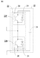
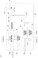
- FIG. 1 is a schematic configuration diagram of a DC transmission power converter according to Embodiment 1 of the present invention.
- the DC transmission power conversion device includes a power converter 1 that is a main circuit and a control device 20 that controls the power converter 1 to be described later.
- the power converter 1 performs power conversion between a plurality of phases of alternating current (here, particularly, three-phase alternating current) and direct current, and the alternating current side is connected to an alternating current power supply 14 that is an alternating current system via an interconnection transformer 13.
- the DC side is connected to the DC power supply 16 via the impedance 15.
- the DC power source 16 in this case, another power conversion device that performs DC output is applied.
- a leg circuit 4 is configured by connecting an AC terminal 7, which is a connection point between the positive arm 5 and the negative arm 6, to an AC line of each phase.
- the leg circuits 4 for three phases are connected in parallel between the positive and negative DC buses 2 and 3.
- the positive side arm 5 and the negative side arm 6 constituting each leg circuit 4 have cell groups 5a and 6a in which a plurality of converter cells 10 are connected in series. Between each cell group 5a, 6a and the AC terminal 7, a positive side reactor 9p and a negative side reactor 9n are respectively inserted in series. In this case, the positive reactor 9p, the negative reactor 9n, and the AC terminal 7 constitute a three-terminal reactor 8.
- the position where the positive side reactor 9p and the negative side reactor 9n are inserted may be any position in each of the arms 5 and 6, and may be plural. Each react value may be different, and in the extreme, it can be inserted only on the positive side or the negative side.
- a transformer is provided for each of the cell groups 5a and 6a. 5a and 6a may be connected in series with each other through the primary winding of each transformer, while the secondary windings of each transformer may be connected to each other and one end thereof may be connected to the AC terminal 7. (See JP-A-2013-115837).
- FIG. 1 A configuration example of each converter cell 10 is shown in FIG. 1
- a converter cell 10 shown in FIG. 2 is a converter cell 10 adopting a half-bridge configuration, and a plurality of (in this case, two) semiconductor switching elements 30 (hereinafter simply referred to as switching) each having a diode 31 connected in antiparallel.
- Each switching element 30 is composed of a self-extinguishing switching element such as an IGBT (Insulated Gate Bipolar Transistor) or a GCT (Gate Commutated Turn-off thyristor), and switches 33P and 33N each having a diode 31 connected in antiparallel. Used.
- a self-extinguishing switching element such as an IGBT (Insulated Gate Bipolar Transistor) or a GCT (Gate Commutated Turn-off thyristor)
- switches 33P and 33N each having a diode 31 connected in antiparallel. Used.
- each converter cell 10 has both terminals of the switching element 30 of the switch 33N as output terminals, and the switching elements 30 of the switches 33N and 33P are turned on and off, so that The voltage across the DC capacitor 34 and the zero voltage are output.
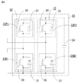
- FIG. 3 shows a configuration example according to another example of each converter cell 10.
- the converter cell 10 shown in FIG. 3 is a converter cell 10 adopting a full-bridge configuration, in which two series bodies 32 are connected in parallel, and are further connected in parallel to the series body 32 so as to smooth a DC voltage. It has.
- Each series body 32 is configured by connecting in series a plurality of (in this case, two) switching elements 30 each having a diode 31 connected in antiparallel.
- the switching element 30 is formed of a self-extinguishing type switching element such as an IGBT or GCT, and switches 33P1, 33P2, 33N1, and 33N2 each including a diode 31 connected in antiparallel are used.
- the converter cell 10 uses the terminal of the switching element 30 serving as an intermediate connection point of each series body 32 as an output terminal, and turns on and off the switching element 30 to thereby output this output terminal. To output a positive voltage, a negative voltage, and a zero voltage across the DC capacitor 34.
- the converter cell 10 includes a series body 32 of a plurality of switching elements 30 and a DC capacitor 34 connected in parallel to the series body 32, and selectively outputs the voltage of the DC capacitor 34 by a switching operation.
- the configuration is not limited to the configuration shown in FIGS. 2 and 3.
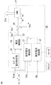
- FIG. 4 is a block diagram showing a configuration example of a control device for a DC transmission power converter according to Embodiment 1 of the present invention.
- the DC current idc flowing through the DC buses 2 and 3 and the capacitor voltage Vcap applied to the DC capacitor 34 of each converter cell 10 are respectively detected by a detector (not shown) and input to the control device 20.
- the DC current idc may be calculated from the currents ip + and ip ⁇ flowing in the positive arm 5 and the negative arm 6 of each phase.
- the alternating current ip of each phase may be calculated from the currents ip + and ip ⁇ flowing through the positive side arm 5 and the negative side arm 6 of each phase.
- the control device 20 adds the outputs of the DC voltage control unit 21, the DC current control unit 22, and the current control unit 25 with adders 23 and 26, thereby controlling the current flowing through the positive arm 5.
- the positive-side arm voltage command value Vp +, the negative-side arm voltage command value Vp for current control flows in the negative-side arm 6 - to produce respectively a.
- the control unit 20 these positive-side arm voltage command Vp + and the negative-side arm voltage command value Vp in the next stage of the PWM control unit 27 - and generates a gate signal 27a on the basis of the respective phase by the gate signal 27a
- the operation of each converter cell 10 of the positive arm 5 and the negative arm 6 is controlled.
- the capacitor voltage control unit 24 controls the capacitor voltage Vcap of the DC capacitor 34 of each converter cell 10 based on the detected capacitor voltage Vcap of each converter cell 10 of each phase.
- the active current command value ipref, the positive arm current command value ip + ref, and the negative arm current command value ip ⁇ ref for voltage control for the DC capacitor 34 are generated for each phase.
- the current control unit 25 detects the current command values (effective current command value ipref, positive arm current command value ip + ref, negative arm current command value ip ⁇ ref) given from the capacitor voltage control unit 24 and each phase. Based on the information of the positive side arm current ip + , the negative side arm current ip ⁇ , and the detected AC current ip of each phase, the AC current for controlling the AC current flowing in the positive side arm 5 and the negative side arm 6 of each phase is controlled. Voltage commands Vpc + and Vpc ⁇ are generated for each phase.
- the voltage commands Vpc + , Vpc ⁇ for controlling the alternating current flowing through the positive arm 5 and the negative arm 6 of each phase are changed to each phase. Generate every.
- the DC voltage control unit 21 controls the DC voltage Vdc between the DC buses 2 and 3 to be detected, the capacitor voltage Vcap of each converter cell 10 in each phase, and the DC voltage supplied from a host controller (not shown). Based on the DC voltage command value Vdcref serving as a target value, a main component of the DC voltage command Vdc * for DC voltage control is generated and output.
- the DC current control unit 22 uses a DC voltage command for DC voltage control based on the detected DC current idc and a DC current command value idcref that is a control target value of a DC current given from a host controller (not shown). A part of Vdc * (DC line impedance component) is generated and output.
- Outputs of the DC voltage control unit 21 and the DC current control unit 22 are added by an adder 23 to generate a DC voltage command Vdc * for DC voltage control.
- the PWM control unit 27 controls the operation of each converter cell 10 by generating a gate signal 27a by pulse width modulation control (PWM control) based on these voltage commands Vp + , Vp ⁇ .
- the voltage output from the cell group 5a of the positive arm 5 and the voltage output from the cell group 6a of the negative arm 6 include the AC voltage component applied to the AC terminal 7 of the interconnection transformer 13, the DC bus 2, 3 includes a DC voltage component output between the three and a voltage component applied to the positive side reactor 9p and the negative side reactor 9n.
- a combined voltage ⁇ Vcap obtained by combining (added value or average value) the capacitor voltages Vcap of all the converter cells 10 constituting the power converter 1 is an effective power flowing from the AC power supply 14 and a DC power flowing to the DC power supply 16. Is converted into a direct current that flows to the DC capacitor 34 in accordance with the switching of each converter cell 10 and is controlled by charging and discharging the DC capacitor 34 of each converter cell 10. Therefore, the composite voltage ⁇ Vcap can be controlled by controlling the effective current flowing through the AC power supply 14.
- the above composite voltage ⁇ Vcap can be controlled by power interchange between the leg circuits 4 of each phase. That is, for example, power can be accommodated by flowing a so-called circulating current between the leg circuits 4 of each phase, so that an imbalance between the phases can be eliminated.
- the capacitor voltage control unit 24 controls the capacitor voltage Vcap of the DC capacitor 34 of each converter cell 10 and the capacitor of each converter cell 10 of each positive arm 5 and each negative arm 6. Based on the detected information of the voltage Vcap, the effective current command value ipref for controlling the effective current flowing in the AC power supply 14, the positive arm current command value ip + ref for controlling the voltage of the positive side arm 5 and the negative side arm 6, and negative Each side arm current command value ip - ref is generated and output.
- the current control unit 25 controls the AC voltage component of the voltage output from the cell groups 5a and 6a and the voltage applied to the reactors 9p and 9n included in the positive and negative arms 5 and 6, respectively. That is, the current control unit 25 performs the current command values (effective current command value ipref, positive arm current command value ip + ref, negative arm current command value ip ⁇ ref) given from the capacitor voltage control unit 24. Feedback control is performed so that the AC current ip of each phase and the positive arm current ip + and negative arm current ip ⁇ detected in each phase coincide with each other, and the AC flowing through the positive arm 5 and the negative arm 6 of each phase. Voltage commands Vpc + and Vpc ⁇ for controlling the current are generated for each phase.
- the DC voltage control unit 21 performs feedback control so that the detected DC voltage Vdc between the DC buses 2 and 3 coincides with the DC voltage command value Vdcref, which is a DC voltage control target value, for DC voltage control.
- the main component of the DC voltage command Vdc * is generated and output.
- the DC current idc flows when a voltage difference between the DC buses 2 and 3 and the voltage of the DC power supply 16 is applied to the impedance 15. Based on this principle, the DC current control unit 22 performs feedback control so that the detected DC current idc coincides with the DC current command value idcref that is the control target value of the DC current, and the DC buses 2 and 3 are connected. A component (a DC line impedance component) of the DC voltage command Vdc * for controlling the DC voltage is generated. Outputs of the DC voltage control unit 21 and the DC current control unit 22 are added by an adder 23 to calculate a DC voltage command Vdc * for DC voltage control.
- the adder 26 at the next stage outputs the voltage commands Vpc + and Vpc for controlling the alternating current of the positive side arm 5 and the negative side arm 6 of each phase output from the current control unit 25, and the adder 23 outputs.
- the PWM control unit 27 generates a gate signal 27a by pulse width modulation control (PWM control) based on each voltage command Vp + , Vp ⁇ .
- the direct-current power supply 16 is connected to another AC / DC conversion terminal (hereinafter referred to as a second AC / DC conversion terminal).
- a second AC / DC conversion terminal the direct-current power supply 16 is connected to another AC / DC conversion terminal (hereinafter referred to as a second AC / DC conversion terminal).
- the DC power supply 16 that is the second AC / DC conversion terminal is configured to include the power converter 1 and the control device 20, in the control device 20 that is the second AC / DC conversion terminal,
- the DC power supply that is the second AC / DC conversion terminal 16 is equivalent to a DC voltage source.
- the control device 20 of the power converter 1 shown in FIG. 4 limits the output of the DC current control unit 22 to be zero, and according to the output of the DC voltage control unit 21, between the DC buses 2 and 3. Therefore, the power converter 1 shown in FIG. 1 operates equivalent to a DC voltage source.
- the DC current control unit 22 of the control device 20 of the DC power supply 16 that is the second AC / DC conversion terminal performs an operation equivalent to the current source
- the control device 20 restricts the output of the DC voltage control unit 21 to zero, and controls the DC voltage Vdc between the DC buses 2 and 3 according to the output of the DC current control unit 22, thereby reducing the impedance.
- An operation equivalent to that of a current source is performed on a DC circuit composed of 15 and a DC power supply 16.
- the plurality of power converters 1 are configured to be DC-connected, there is at least one AC / DC conversion terminal for controlling the DC voltage Vdc, and the rest are AC / DC conversion terminals for controlling the DC current idc. .
- the control device 20 of the power converter 1 limits the output of the DC current control unit 22 to zero and performs control according to the output of the DC voltage control unit 21, that is, the power converter 1 shown in FIG.
- a system fault instantaneous drop
- the AC power is reduced, the balance with the DC power is lost, and differential power is generated.
- the DC capacitor 34 of each converter cell 10 is charged / discharged in accordance with the generation of this differential power.
- the DC voltage control unit 21 synthesizes (adds or averages) the capacitor voltage Vcap of all the converter cells 10 of each phase based on the detected information of the capacitor voltage Vcap of each DC capacitor 34.
- the magnitude of ⁇ Vcap exceeds a preset first predetermined value ⁇ Vmax or falls below a second predetermined value ⁇ Vmin ( ⁇ Vmax)
- the direction of the DC current idc or its DC current command value idcref Accordingly, the DC voltage command value Vdcref is increased or decreased by a preset fixed value ⁇ Vdcref.
- the first predetermined value ⁇ Vmax is set to be equal to or lower than the overvoltage level of the capacitor voltage Vcap at which the converter cell 10 detects a failure.
- the second predetermined value ⁇ Vmin is preferably set to be equal to or higher than the low voltage level of the capacitor voltage Vcap at which the converter cell 10 detects a failure.
- the fixed value ⁇ Vdcref is desirably set according to the magnitude of the resistance component of the impedance 15.
- the DC voltage command value Vdcref is decreased to suppress the amount of direct current idc flowing out of the power converter 1.
- the magnitude of the composite voltage ⁇ Vcap is lower than a preset second predetermined value ⁇ Vmin and the DC current idc flows from the DC power supply 16 to the power converter 1
- the DC voltage command The value Vdcref is increased to suppress the amount of direct current idc flowing into the power converter 1.
- This control reduces the magnitude of the DC power by reducing the magnitude of the DC current idc.
- fluctuations in the capacitor voltage Vcap due to charging / discharging of the DC capacitor 34 of each converter cell 10 due to a decrease in AC power due to a voltage decrease in the AC power supply 14 due to the occurrence of a system fault (instantaneous drop) or the like are suppressed. be able to.
- the magnitude of the DC power is reduced by reducing the magnitude of the DC current idc.
- the effective current command value ipref output from the capacitor voltage control unit 24 remains within the limit, and the AC and DC power can be balanced.
- the DC voltage command value Vdcref is fixed irrespective of the cancellation of the AC system fault. The process of increasing or decreasing by the value ⁇ Vdcref is stopped and returned to the original DC voltage command value Vdcref.
- the DC current control unit 22 of the control device 20 limits the output.
- the output is larger than the DC voltage generated by the magnitude of the resistance component of the impedance 15, but is controlled by the DC voltage command value ⁇ Vdcref. It is desirable to limit to a value smaller than the DC voltage change.
- the capacitor voltage Vcap of each converter cell 10 fluctuates due to the occurrence of a system fault (instantaneous drop) in which the magnitude of the AC voltage Vp decreases in the AC power supply 14.
- the DC voltage command value Vdcref of the DC voltage control unit 21 is controlled in accordance with the fluctuation of the capacitor voltage Vcap, thereby adjusting the magnitude of the DC power and reducing the AC power due to the voltage drop of the AC power supply 14.
- AC power and DC power can be balanced.
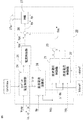
- FIG. FIG. 5 is a block diagram showing a configuration example of a control device for a DC transmission power converter according to Embodiment 2 of the present invention.
- the configuration of the power converter 1 is the same as that of the first embodiment shown in FIG. 1, but the configuration of the control device 20 is different from that of the first embodiment.
- the capacitor voltage control unit 24 controls all the converters of each detected phase in order to control the capacitor voltage Vcap of each converter cell 10 as in the case of the first embodiment. Based on the information of the capacitor voltage Vcap of the cell 10, current command values (effective current command value ipref, positive arm current command value ip + ref, negative arm current command value ip ⁇ ref) are generated and supplied to the current control unit 25. give.
- the effective current command value ipref output from the capacitor voltage control unit 24 adjusts the effective current flowing through the AC power supply 14 in order to feedback control the combined voltage ⁇ Vcap of the capacitor voltage Vcap of all the converter cells 10 of each phase.
- the effective current command value ipref is limited by the current value that the power converter 1 can flow, that is, the current capacity.
- a limit value iprefmax is provided for the active current command value ipref so that the value falls within a predetermined range (limiter function).
- the current control unit 25 receives the current command values (effective current command value ipref, positive arm current command value ip + ref, negative arm current command value ip ⁇ ) given from the capacitor voltage control unit 24. and ref), each detected current ip, ip +, ip - based on the information, each arm voltage command Vp +, Vp - of the voltage of the AC current control to flow to the positive arm 5 and the negative-side arm 6 Commands Vpc + and Vpc ⁇ are generated for each phase.
- the current command values (effective current command value ipref, positive arm current command value ip + ref, negative arm current command value ip ⁇ ) given from the capacitor voltage control unit 24. and ref)
- the direct current calculation unit 28 includes the above-described effective current excess component ⁇ ip given from the capacitor voltage control unit 24, the detected direct current voltage Vdc between the direct current buses 2 and 3, and the alternating current power supply 14 side or power of the interconnection transformer 13 Based on the information of the AC voltage Vp of each phase detected on the converter 1 side, a DC current excess component ⁇ idc as a DC conversion value of the effective current excess component ⁇ ip is obtained, and this DC current excess component ⁇ idc is obtained as a DC current control unit. 22 to output.
- the DC voltage control unit 21 does not receive the detection output of the capacitor voltage Vcap of each converter cell 10 and receives only the information of the DC voltage Vdc between the DC buses 2 and 3. Has been.
- the DC voltage control unit 21 performs feedback control so that the DC voltage Vdc coincides with a DC voltage command value Vdcref that is a DC voltage control target value given from a host controller (not shown).
- the main component of the DC voltage command Vdc * is generated and output.
- the DC current control unit 22 detects the detected DC current idc, the DC current command value idcref that is the control target value of the DC current supplied from a host controller (not shown), and the DC current supplied from the DC current calculation unit 28 described above. Based on the information of the excess current component ⁇ idc, a part of the DC voltage command Vdc * for DC voltage control (impedance component of the DC line) is generated and output.
- the outputs of the DC voltage control unit 21 and the DC current control unit 22 are added by an adder 23 to generate a DC voltage command Vdc * for DC voltage control.
- Vdc * and is summed positive side arm voltage command Vp + and the negative-side arm voltage command Vp - is obtained.
- the PWM control unit 27 controls the operation of each converter cell 10 by generating a gate signal 27a by pulse width modulation control (PWM control) based on these voltage commands Vp + , Vp ⁇ .
- the limit value irefmax is provided for the active current command value ireff output from the capacitor voltage control unit 24 so that it falls within a predetermined range (limiter function). That is, in the feedback control of the composite voltage ⁇ Vcap, the effective current command value ipref is obtained by amplifying the deviation between the composite voltage ⁇ Vcap and a preset command value. If the deviation is large, the effective current command value ipref is obtained. Is limited by the limit value irefmax, so that a deviation occurs before and after the limit.
- the active power excess ⁇ ip in this case may be calculated from the product sum of the instantaneous voltage and current of the three-phase alternating current, or the three-phase alternating current is converted into an orthogonal coordinate system and the voltage and current are similarly converted. You may calculate from the sum of products. At this time, it is desirable to configure a filter that removes the double frequency and the double frequency of the frequency of the AC power supply 14 included in the power P generated at the time of unbalance or transient.
- the DC current calculation unit 28 calculates the active power excess ⁇ P based on the active current excess component ⁇ ip output from the capacitor voltage control unit 24 and the detected magnitude of the AC voltage Vp. Next, the DC current calculation unit 28 divides the active power excess ⁇ P by the DC voltage Vdc to obtain a DC current excess component ⁇ idc as a DC conversion value of the active current excess component ⁇ ip. This calculation is derived from the condition where AC power and DC power are balanced. The direct current excess component ⁇ idc calculated by the direct current calculation unit 28 is given to the direct current control unit 22.
- the value of the DC voltage Vdc before division is limited to a predetermined value or more in consideration of the operating range of the DC voltage Vdc, and the voltage drop of the DC power supply 16 is reduced. It is desirable that excessive ⁇ idc is not calculated by division at the time of a short circuit failure between the DC buses 2 and 3.
- the direct current control unit 22 performs the following based on each information of the direct current excess component ⁇ idc given from the direct current calculation unit 28, the detected direct current idc, and the direct current command value idcref that becomes the control target value of the direct current. Perform the process.
- the DC current control unit 22 performs correction for subtracting the DC current excess component ⁇ idc from the DC current command value idcref that is a control target value of the DC current.
- the power desired to flow into the power converter 1 from the AC power supply 14 is insufficient due to the limitation of the effective current command value ipref, but the DC current command value idcref is decreased by the DC current excess component ⁇ idc. Can be balanced.
- the DC current control unit 22 performs correction by adding the DC current excess component ⁇ idc to the DC current command value idcref that is the control target value of the DC current.
- the power to be discharged from the power converter 1 to the AC power supply 14 is insufficient due to the limitation of the effective current command value ipref, but the DC current command value idcref is increased by the DC current excess component ⁇ idc. Can be balanced.
- the DC current control unit 22 performs feedback control so that the detected DC current idc matches the corrected DC current command value (idcref ⁇ idc) or (idcref + ⁇ idc), and the DC buses 2, 3, A part of the direct-current voltage command Vdc * is generated and output so as to control the direct-current voltage Vdc.
- the DC voltage control unit 21 is feedback-controlled so that the DC voltage Vdc between the DC buses 2 and 3 coincides with the DC voltage command value Vdcref, and a DC voltage command for controlling the DC voltage Vdc between the DC buses 2 and 3.
- a part of Vdc * component (DC line impedance component) is generated and output.
- the adder 23 adds the output of the DC voltage control unit 21 and the output of the DC current control unit 22 to calculate a DC voltage command Vdc * for DC voltage control.
- the adder 26 in the next stage is obtained by the adder 23 with the voltage components Vpc + and Vpc ⁇ for controlling the alternating current of the positive side arm 5 and the negative side arm 6 of each phase output from the current control unit 25.
- DC voltage command Vdc * and adds the DC voltage control, the positive side arm voltage command Vp + and the negative-side arm voltage command Vp - calculating a.
- the PWM control unit 27 generates a gate signal 27a by pulse width modulation control (PWM control) based on each voltage command Vp + , Vp ⁇ .
- PWM control pulse width modulation control
- the direct-current power supply 16 will be another AC / DC conversion terminal.
- the power converter 1 connected to the direct current has at least one AC / DC conversion terminal for controlling the DC voltage Vdc, and the others are AC / DC conversion terminals for controlling the DC current idc. Since details in this case have already been described in the first embodiment, detailed description thereof is omitted here.
- the capacitor voltage control unit 24 when the capacitor voltage control unit 24 performs feedback control of the combined voltage ⁇ Vcap obtained by combining (added value or average value) the capacitor voltages of all the converter cells 10, the effective current Even when the command value ipref is limited by the limiter function, the DC current control unit 22 operates so as to correct the DC current command value idcref serving as the DC current control target value with the DC current excess component ⁇ idc. The balance between the power and the DC output can be maintained, and the feedback control of the composite voltage ⁇ Vcap functions.
- the capacitor voltage Vcap of each converter cell 10 fluctuates due to the occurrence of a system fault (instantaneous drop) in which the magnitude of the AC voltage decreases in the AC power supply 14, the fluctuation in the capacitor voltage Vcap occurs. Accordingly, since the feedback control of the composite voltage ⁇ Vcap functions, the capacitor voltage Vcap of the DC capacitor 34 of each converter cell 10 can be stably maintained, and each AC / DC conversion terminal that mainly controls the DC current can The fluctuation of the capacitor voltage Vcap of the converter cell 10 can be suppressed and the operation can be continued without detecting a failure.
- FIG. FIG. 6 is a block diagram showing a configuration example of a control device for a DC transmission power converter according to Embodiment 3 of the present invention.
- the configuration of the power converter 1 is the same as that of the first embodiment shown in FIG. 1, but the configuration of the control device 20 is slightly different from those of the first and second embodiments. .
- the configurations of the DC voltage control unit 21 and the current control unit 25 are the same as those in the first embodiment, and the capacitor voltage control unit 24, the DC current calculation unit 28, and the adders 23 and 26.
- the configuration of the PWM control unit 27 is the same as that of the second embodiment.
- the DC current control unit 22 is detected in addition to the detected DC current idc and the DC current excess component ⁇ idc calculated by the DC current calculation unit 28 being input.
- the capacitor voltage Vcap of all the converter cells 10 of each phase is input.
- the direct current control unit 22 outputs a partial component (impedance component of the direct current line) of the direct current voltage command Vdc * based on these pieces of information.
- the DC current control unit 22 synthesizes (adds or averages) the capacitor voltages of all the converter cells 10 of each phase based on the detected information on the capacitor voltage Vcap of each DC capacitor 34. Is larger than a first predetermined value ⁇ Vmax set in advance or lower than a second predetermined value ⁇ Vmin ( ⁇ Vmax), the DC current control unit 22 is limited and the output is limited. The zero function is canceled and the feedback control of the DC current control unit 22 is activated.
- the DC current control unit 22 performs the same as in the second embodiment, in the case where the DC current idc has a polarity representing the power flowing out from the power converter 1 to the DC power supply 16, and the DC current idc. Is obtained by subtracting or adding the direct current excess component ⁇ idc to the direct current command value idcref, which is the control target value of the direct current, depending on the case of the polarity representing the power flowing into the power converter 1 from the direct current power supply 16 I do.
- the DC current control unit 22 performs feedback control so that the detected DC current idc matches the corrected DC current command value (idcref ⁇ idc) or (idcref + ⁇ idc). A part of the component of the DC voltage command Vdc * is generated and output so as to control the DC voltage Vdc.
- a DC voltage component Vdc + is to vary slowly - first voltage command Vp + and the second voltage command Vp.
- DC voltage control unit 21, current control unit 25, and PWM control unit 27 are the same as those of the first embodiment, and capacitor voltage control unit 24 and DC current calculation unit Since the operation 28 is the same as that of the second embodiment, detailed description thereof is omitted here.
- the DC voltage control unit 21 is the same as in the first embodiment in accordance with the fluctuation of ⁇ Vcap obtained by combining (added value or average value) the capacitor voltages of all the converter cells 10.
- the DC current control unit 22 converts the DC current command value idcref, which is a control target value of the DC current, to the DC current excess component ⁇ idc. Therefore, even in the AC / DC converter terminal that mainly controls the DC voltage, the AC power and the DC power are balanced and the fluctuation of the capacitor voltage Vcap of each converter cell 10 is suppressed to detect the failure. It is possible to continue operation.
- the present invention is not limited to the configurations of the first to third embodiments described above, and modifications may be made to some of the configurations of the first to third embodiments without departing from the spirit of the present invention.
- a part of the configuration can be omitted, and the configurations of the first to third embodiments can be appropriately combined.
Abstract
Description
そして、上記制御装置は、上記正側アームと上記負側アームを構成する各々の上記変換器セルを出力制御するものであって、
各々の上記直流コンデンサの電圧(Vcap)に基づいて当該直流コンデンサに対する電圧制御用の電流指令値(ipref、ip+ref、ip-ref)を生成するコンデンサ電圧制御部と、
上記コンデンサ電圧制御部からの上記電流指令値(ipref、ip+ref、ip-ref)に基づいて、上記正側アームに流れる電流制御用の正側アーム電圧指令(Vp+)と上記負側アームに流れる電流制御用の負側アーム電圧指令(Vp-)の内の交流電流制御用の電圧指令(Vpc+、Vpc-)を生成する電流制御部と、
上記直流母線の間の直流電圧(Vdc)と上記直流母線に流れる直流電流(idc)、および予め設定された制御目標値となる指令値(Vdcref、idcref)に基づいて、上記正側アーム電圧指令(Vp+)と上記負側アーム電圧指令(Vp-)の内の直流電圧制御用の直流電圧指令(Vdc*)を生成する直流制御部とを有し、
上記直流制御部に与える上記指令値(Vdcrefまたはidcref)を、上記直流コンデンサの電圧変動の検出量に応じて補正する。 The direct-current transmission power converter according to the present invention includes a plurality of leg circuits in which a positive arm and a negative arm corresponding to each phase are connected in series, and a connection point thereof is connected to an AC line of each phase, Each of the leg circuits includes a power converter that is connected in parallel between positive and negative DC buses and performs power conversion between a plurality of phases of AC and DC, and a control device that controls the power converter, Each of the positive arm and the negative arm constituting the leg circuit is formed by connecting at least one of converter cells in series, and the converter cell includes a plurality of semiconductor switching elements connected in series. It is composed of a series body and a DC capacitor connected in parallel to the series body.
And the said control apparatus carries out output control of each said converter cell which comprises the said positive side arm and the said negative side arm,
A capacitor voltage control unit that generates a current command value (ipref, ip + ref, ip − ref) for voltage control for the DC capacitor based on the voltage (Vcap) of each DC capacitor;
Based on the current command values (ipref, ip + ref, ip − ref) from the capacitor voltage control unit, the positive arm voltage command (Vp + ) for controlling the current flowing in the positive arm and the negative arm A current control unit that generates an AC current control voltage command (Vpc + , Vpc − ) out of a negative arm voltage command (Vp − ) for current control flowing through
Based on the DC voltage (Vdc) between the DC buses, the DC current (idc) flowing through the DC bus, and command values (Vdcref, idcref) that are preset control target values, the positive arm voltage command (Vp + ) and a DC control unit that generates a DC voltage command (Vdc * ) for DC voltage control in the negative arm voltage command (Vp − ),
The command value (Vdcref or idcref) given to the DC control unit is corrected according to the detected amount of voltage fluctuation of the DC capacitor.
すなわち、上記制御装置が、上記正側アームと上記負側アームを構成する各々の上記変換器セルを出力制御する際に、
各々の上記直流コンデンサの電圧(Vcap)に基づいて当該直流コンデンサに対する電圧制御用の電流指令値(ipref、ip+ref、ip-ref)を生成し、
上記電流指令値(ipref、ip+ref、ip-ref)に基づいて、上記正側アームに流れる電流制御用の正側アーム電圧指令(Vp+)と上記負側アームに流れる電流制御用の負側アーム電圧指令(Vp-)の内の交流電流制御用の電圧指令(Vpc+、Vpc-)を生成し、
上記直流母線の間の直流電圧(Vdc)と上記直流母線に流れる直流電流(idc)、および予め設定された制御目標値となる指令値(Vdcref、idcref)に基づいて、上記正側アーム電圧指令(Vp+)と上記負側アーム電圧指令(Vp-)の内の直流電圧制御用の直流電圧指令(Vdc*)を生成し、
上記指令値(Vdcrefまたはidcref)を、上記直流コンデンサの電圧変動の検出量に応じて補正する。 The DC transmission power conversion method according to the present invention includes a plurality of leg circuits in which a positive arm and a negative arm corresponding to each phase are connected in series, and a connection point thereof is connected to an AC line of each phase. Each of the leg circuits includes a power converter that is connected in parallel between positive and negative DC buses and performs power conversion between a plurality of phases of AC and DC, and a control device that controls the power converter. Each of the positive side arm and the negative side arm constituting each leg circuit includes at least one converter cell connected in series, and the converter cell includes a plurality of semiconductor switching devices connected in series. In the case where the device is composed of a series body of elements and a DC capacitor connected in parallel to the series body, the following method is adopted.
That is, when the control device performs output control of each of the converter cells constituting the positive arm and the negative arm,
Based on the voltage (Vcap) of each of the DC capacitors, a current command value (ipref, ip + ref, ip − ref) for voltage control for the DC capacitor is generated,
Based on the current command values (ipref, ip + ref, ip − ref), a positive arm voltage command (Vp + ) for current control flowing through the positive arm and a negative for current control flowing through the negative arm. side arm voltage command (Vp -) voltage command of the AC current control of the (Vpc +, Vpc -) generates,
Based on the DC voltage (Vdc) between the DC buses, the DC current (idc) flowing through the DC bus, and command values (Vdcref, idcref) that are preset control target values, the positive arm voltage command (Vp + ) and a DC voltage command (Vdc * ) for DC voltage control within the negative arm voltage command (Vp − ) are generated,
The command value (Vdcref or idcref) is corrected according to the detected amount of voltage fluctuation of the DC capacitor.
図1は、この発明の実施の形態1による直流送電電力変換装置の概略構成図である。
FIG. 1 is a schematic configuration diagram of a DC transmission power converter according to
また、各セル群5a、6aと交流端7との間に正側リアクトル9pと負側リアクトル9nをそれぞれ挿入する代わりに、各セル群5a、6aに対して個別にトランスを設け、各セル群5a、6aを各トランスの一次巻線を介して互いに直列に接続する一方、各トランスの二次巻線を互いに接続してその一端部を交流端7に接続した構成とすることも可能である(特開平2013-115837号公報参照)。 In addition, the position where the
Further, instead of inserting the
各相の正側アーム5と負側アーム6に流れる正側アーム電流ip+と負側アーム電流ip-、各相の交流線に流れる交流電流ip、直流母線2、3間の直流電圧Vdc、直流母線2、3に流れる直流電流idc、および各変換器セル10の直流コンデンサ34に加わるコンデンサ電圧Vcapは、それぞれ図示しない検出器によって検出されて制御装置20に入力される。 FIG. 4 is a block diagram showing a configuration example of a control device for a DC transmission power converter according to
Positive arm current ip + and negative arm current ip − flowing in the
図5は、この発明の実施の形態2による直流送電電力変換装置の制御装置の構成例を示すブロック図である。
FIG. 5 is a block diagram showing a configuration example of a control device for a DC transmission power converter according to
図6は、この発明の実施の形態3による直流送電電力変換装置の制御装置の構成例を示すブロック図である。
FIG. 6 is a block diagram showing a configuration example of a control device for a DC transmission power converter according to
Claims (9)
- 各相に対応した正側アームと負側アームとが直列接続され、その接続点が各相の交流線に接続されてなる複数のレグ回路を備え、各々の上記レグ回路は正負の直流母線の間に並列接続されて複数相の交流と直流との間で電力変換を行う電力変換器と、上記電力変換器を制御する制御装置とを備え、各々の上記レグ回路を構成する上記正側アームと上記負側アームのそれぞれは、変換器セルの少なくとも一つを直列接続してなり、上記変換器セルは、直列接続された複数の半導体スイッチング素子の直列体と、この直列体に並列接続された直流コンデンサとから構成されている直流送電電力変換装置において、
上記制御装置は、上記正側アームと上記負側アームを構成する各々の上記変換器セルを出力制御するものであって、
各々の上記直流コンデンサの電圧(Vcap)に基づいて上記直流コンデンサに対する電圧制御用の電流指令値(ipref、ip+ref、ip-ref)を生成するコンデンサ電圧制御部と、
上記コンデンサ電圧制御部からの上記電流指令値(ipref、ip+ref、ip-ref)に基づいて、上記正側アームに流れる電流制御用の正側アーム電圧指令(Vp+)と上記負側アームに流れる電流制御用の負側アーム電圧指令(Vp-)の内の交流電流制御用の電圧指令(Vpc+、Vpc-)を生成する電流制御部と、
上記直流母線の間の直流電圧(Vdc)と上記直流母線に流れる直流電流(idc)、および予め設定された制御目標値となる指令値(Vdcref、idcref)に基づいて、上記正側アーム電圧指令(Vp+)と上記負側アーム電圧指令(Vp-)の内の直流電圧制御用の直流電圧指令(Vdc*)を生成する直流制御部とを有し、
上記直流制御部に与える上記指令値(Vdcrefまたはidcref)を、上記直流コンデンサの電圧変動の検出量に応じて補正する直流送電電力変換装置。 A positive arm and a negative arm corresponding to each phase are connected in series, and a plurality of leg circuits each having a connection point connected to an AC line of each phase are provided, and each of the leg circuits includes a positive and negative DC bus. A power converter that performs power conversion between a plurality of phases of alternating current and direct current, connected in parallel, and a control device that controls the power converter, and the positive arm that constitutes each of the leg circuits And each of the negative side arms comprises at least one converter cell connected in series, and the converter cell is connected in series to a series body of a plurality of semiconductor switching elements connected in series. In a direct current transmission power conversion device composed of a direct current capacitor,
The control device controls the output of each of the converter cells constituting the positive side arm and the negative side arm,
A capacitor voltage control unit that generates a current command value (ipref, ip + ref, ip − ref) for voltage control on the DC capacitor based on the voltage (Vcap) of each DC capacitor;
Based on the current command values (ipref, ip + ref, ip − ref) from the capacitor voltage control unit, the positive arm voltage command (Vp + ) for controlling the current flowing in the positive arm and the negative arm A current control unit that generates an AC current control voltage command (Vpc + , Vpc − ) out of a negative arm voltage command (Vp − ) for current control flowing through
Based on the DC voltage (Vdc) between the DC buses, the DC current (idc) flowing through the DC bus, and command values (Vdcref, idcref) that are preset control target values, the positive arm voltage command (Vp + ) and a DC control unit that generates a DC voltage command (Vdc * ) for DC voltage control in the negative arm voltage command (Vp − ),
A direct-current transmission power converter that corrects the command value (Vdcref or idcref) given to the direct-current control unit in accordance with a detected amount of voltage fluctuation of the direct-current capacitor. - 上記直流制御部は、上記直流母線の間の電圧(Vdc)、上記直流コンデンサの合成電圧(ΣVcap)、および上記指令値(Vdcref)に基づいて、上記直流電圧指令(Vdc*)の主成分を生成する直流電圧制御部を備えており、
上記直流コンデンサの電圧変動の検出は、上記直流コンデンサの合成電圧(ΣVcap)が予め設定された第1の所定値(ΔVmax)を超えるか、または、上記第1の所定値(ΔVmax)よりも小さく設定された第2の所定値(ΔVmin)よりも小さくなったことにより検出し、
この検出に応じて、上記直流電圧制御部に対して設定された上記指令値(Vdcref)を、上記直流電流(idc)または直流電流制御用の上記指令値(idcref)の極性に応じて、予め設定した固定値(ΔVdcref)分だけ加算または減算することで補正する請求項1に記載の直流送電電力変換装置。 The DC control unit is configured to generate a main component of the DC voltage command (Vdc * ) based on the voltage (Vdc) between the DC buses, the combined voltage (ΣVcap) of the DC capacitor, and the command value (Vdcref). It has a DC voltage controller to generate,
The voltage fluctuation of the DC capacitor is detected by detecting whether the combined voltage (ΣVcap) of the DC capacitor exceeds a preset first predetermined value (ΔVmax) or smaller than the first predetermined value (ΔVmax). Detected by becoming smaller than the set second predetermined value (ΔVmin),
In response to this detection, the command value (Vdcref) set for the DC voltage control unit is preliminarily determined according to the polarity of the DC current (idc) or the command value (idcref) for DC current control. The DC transmission power converter according to claim 1, wherein correction is performed by adding or subtracting only a set fixed value (ΔVdcref). - 上記直流制御部は、上記直流母線に流れる直流電流(idc)、および上記指令値(idcref)に基づいて、上記直流電圧指令(Vdc*)の一部の成分を生成する直流電流制御部を備えており、
上記直流コンデンサの電圧変動の検出は、上記コンデンサ電圧制御部が生成する上記電流指令値(ipref)が上記コンデンサ電圧制御部に対して予め設定された制限値(iprefmax)を超過したことにより検出し、
この検出に応じて、上記直流電流制御部に設定された上記指令値(idcref)を、上記電流指令値の制限値(iprefmax)の超過分(Δip)と、各相の交流電圧(Vp)、および上記直流電圧(Vdc)とから演算して得られる直流電圧超過成分(Δidc)に基づいて補正する請求項1に記載の直流送電電力変換装置。 The DC control unit includes a DC current control unit that generates a component of the DC voltage command (Vdc * ) based on the DC current (idc) flowing through the DC bus and the command value (idcref). And
The voltage fluctuation of the DC capacitor is detected when the current command value (iref) generated by the capacitor voltage control unit exceeds a limit value (irefmax) set in advance for the capacitor voltage control unit. ,
In response to this detection, the command value (idcref) set in the DC current control unit is set to an excess (Δip) of the limit value (iprefmax) of the current command value, an AC voltage (Vp) of each phase, The DC transmission power converter according to claim 1, wherein correction is performed based on a DC voltage excess component (Δidc) obtained by calculation from the DC voltage (Vdc). - 上記直流制御部は、上記直流母線の間の電圧(Vdc)、上記直流コンデンサの合成電圧(ΣVcap)、および上記指令値(Vdcref)に基づいて、上記直流電圧指令(Vdc*)の主成分を生成する直流電圧制御部と、上記直流母線に流れる直流電流(idc)、および上記指令値(idcref)に基づいて、上記直流電圧指令(Vdc*)の一部の成分を生成する直流電流制御部とを備えており、
上記直流コンデンサの電圧変動の検出は、上記直流コンデンサの合成電圧(ΣVcap)が予め設定された第1の所定値(ΔVmax)を超えるか、または、上記第1の所定値(ΔVmax)よりも小さく設定された第2の所定値(ΔVmin)よりも小さくなったことにより検出し、
この検出に応じて、上記直流電圧制御部に対して設定された上記指令値(Vdcref)を、上記直流電流(idc)または直流電流制御用の上記指令値(idcref)の極性に応じて、予め設定した固定値(ΔVdcref)分だけ加算または減算することで補正するとともに、上記直流電流制御部に設定された上記指令値(idcref)を、上記電流指令値の制限値(iprefmax)の超過分(Δip)と、各相の交流電圧(Vp)、および上記直流電圧(Vdc)とから演算して得られる直流電圧超過成分(Δidc)に基づいて補正する請求項1に記載の直流送電電力変換装置。 The DC control unit is configured to generate a main component of the DC voltage command (Vdc * ) based on the voltage (Vdc) between the DC buses, the combined voltage (ΣVcap) of the DC capacitor, and the command value (Vdcref). A direct current voltage control unit that generates, and a direct current control unit that generates a part of the direct current voltage command (Vdc * ) based on the direct current (idc) flowing through the direct current bus and the command value (idcref) And
The voltage fluctuation of the DC capacitor is detected by detecting whether the combined voltage (ΣVcap) of the DC capacitor exceeds a preset first predetermined value (ΔVmax) or smaller than the first predetermined value (ΔVmax). Detected by becoming smaller than the set second predetermined value (ΔVmin),
In response to this detection, the command value (Vdcref) set for the DC voltage control unit is preliminarily determined according to the polarity of the DC current (idc) or the command value (idcref) for DC current control. Correction is made by adding or subtracting the set fixed value (ΔVdcref), and the command value (idcref) set in the DC current control unit is exceeded by an amount exceeding the limit value (iprefmax) of the current command value ( The DC transmission power converter according to claim 1, wherein the correction is based on a DC voltage excess component (Δidc) obtained by calculating from Δip), an AC voltage (Vp) of each phase, and the DC voltage (Vdc). . - 上記直流コンデンサの合成電圧(ΣVcap)が上記第1の所定値(ΔVmax)以下、かつ、上記第2の所定値(ΔVmim)以上を検出した場合には、上記直流電圧制御部における上記指令値(Vdcref)の補正を停止する請求項2または請求項4に記載の直流送電電力変換装置。 When the composite voltage (ΣVcap) of the DC capacitor is detected to be not more than the first predetermined value (ΔVmax) and not less than the second predetermined value (ΔVmim), the command value ( The DC transmission power converter according to claim 2 or 4, wherein the correction of Vdcref) is stopped.
- 上記直流電流(idc)の大きさが予め設定した所定値以下になったことを検出した場合には、上記直流電流制御部における上記指令値(idcref)の補正を停止する請求項3または請求項4に記載の直流送電電力変換装置。 The correction of the command value (idcref) in the DC current control unit is stopped when it is detected that the magnitude of the DC current (idc) is equal to or less than a predetermined value set in advance. 4. The DC transmission power conversion device according to 4.
- 上記直流電圧制御部における上記指令値(Vdcref)の補正を停止する場合、補正された指令値から補正前の指令値への変化を緩やかにした請求項5に記載の直流送電電力変換装置。 6. The DC transmission power converter according to claim 5, wherein when the correction of the command value (Vdcref) in the DC voltage control unit is stopped, the change from the corrected command value to the command value before correction is moderated.
- 上記直流電流制御部における上記指令値(idcref)の補正を停止する場合、上記正側アーム電圧指令(Vp+)と上記負側アーム電圧指令(Vp-)の直流電圧成分(Vdc*)が緩やかに変化するようにした請求項6に記載の直流送電電力変換装置。 When the correction of the command value (idcref) in the DC current control unit is stopped, the DC voltage component (Vdc * ) of the positive arm voltage command (Vp + ) and the negative arm voltage command (Vp − ) is moderate. The direct-current transmission power conversion device according to claim 6, which changes to
- 各相に対応した正側アームと負側アームとが直列接続され、その接続点が各相の交流線に接続されてなる複数のレグ回路を備え、各々の上記レグ回路は正負の直流母線の間に並列接続されて複数相の交流と直流との間で電力変換を行う電力変換器と、この電力変換器を制御する制御装置とを備え、各々の上記レグ回路を構成する上記正側アームと上記負側アームのそれぞれは、変換器セルの少なくとも一つを直列接続してなり、上記変換器セルは、直列接続された複数の半導体スイッチング素子の直列体と、この直列体に並列接続された直流コンデンサとから構成されている場合において、
上記制御装置が、上記正側アームと上記負側アームを構成する各々の上記変換器セルを出力制御する際に、
各々の上記直流コンデンサの電圧(Vcap)に基づいて当該直流コンデンサに対する電圧制御用の電流指令値(ipref、ip+ref、ip-ref)を生成し、
上記電流指令値(ipref、ip+ref、ip-ref)に基づいて、上記正側アームに流れる電流制御用の正側アーム電圧指令(Vp+)と上記負側アームに流れる電流制御用の負側アーム電圧指令(Vp-)の内の交流電流制御用の電圧指令(Vpc+、Vpc-)を生成し、
上記直流母線の間の直流電圧(Vdc)と上記直流母線に流れる直流電流(idc)、および予め設定された制御目標値となる指令値(Vdcref、idcref)に基づいて、上記正側アーム電圧指令(Vp+)と上記負側アーム電圧指令(Vp-)の内の直流電圧制御用の直流電圧指令(Vdc*)を生成し、
上記指令値(Vdcrefまたはidcref)を、上記直流コンデンサの電圧変動の検出量に応じて補正する直流送電電力変換方法。 A positive arm and a negative arm corresponding to each phase are connected in series, and a plurality of leg circuits each having a connection point connected to an AC line of each phase are provided, and each of the leg circuits includes a positive and negative DC bus. A power converter that performs parallel power conversion between a plurality of phases of alternating current and direct current, and a control device that controls the power converter, and that constitutes each of the leg circuits. And each of the negative side arms comprises at least one converter cell connected in series, and the converter cell is connected in series to a series body of a plurality of semiconductor switching elements connected in series. In the case where it is configured with a direct current capacitor,
When the control device performs output control of each of the converter cells constituting the positive arm and the negative arm,
Based on the voltage (Vcap) of each of the DC capacitors, a current command value (ipref, ip + ref, ip − ref) for voltage control for the DC capacitor is generated,
Based on the current command values (ipref, ip + ref, ip − ref), a positive arm voltage command (Vp + ) for current control flowing through the positive arm and a negative for current control flowing through the negative arm. side arm voltage command (Vp -) voltage command of the AC current control of the (Vpc +, Vpc -) generates,
Based on the DC voltage (Vdc) between the DC buses, the DC current (idc) flowing through the DC bus, and command values (Vdcref, idcref) that are preset control target values, the positive arm voltage command (Vp + ) and a DC voltage command (Vdc * ) for DC voltage control within the negative arm voltage command (Vp − ) are generated,
A DC transmission power conversion method for correcting the command value (Vdcref or idcref) in accordance with a detected amount of voltage fluctuation of the DC capacitor.
Priority Applications (3)
| Application Number | Priority Date | Filing Date | Title |
|---|---|---|---|
| EP15795713.5A EP3148067B1 (en) | 2014-05-21 | 2015-05-19 | Direct-current power transmission power conversion device and direct-current power transmission power conversion method |
| US15/305,586 US9755542B2 (en) | 2014-05-21 | 2015-05-19 | Direct-current power transmission power conversion device and direct-current power transmission power conversion method |
| JP2016521106A JP6207730B2 (en) | 2014-05-21 | 2015-05-19 | DC transmission power conversion apparatus and DC transmission power conversion method |
Applications Claiming Priority (2)
| Application Number | Priority Date | Filing Date | Title |
|---|---|---|---|
| JP2014104869 | 2014-05-21 | ||
| JP2014-104869 | 2014-05-21 |
Publications (1)
| Publication Number | Publication Date |
|---|---|
| WO2015178376A1 true WO2015178376A1 (en) | 2015-11-26 |
Family
ID=54554044
Family Applications (1)
| Application Number | Title | Priority Date | Filing Date |
|---|---|---|---|
| PCT/JP2015/064327 WO2015178376A1 (en) | 2014-05-21 | 2015-05-19 | Direct-current power transmission power conversion device and direct-current power transmission power conversion method |
Country Status (4)
| Country | Link |
|---|---|
| US (1) | US9755542B2 (en) |
| EP (1) | EP3148067B1 (en) |
| JP (1) | JP6207730B2 (en) |
| WO (1) | WO2015178376A1 (en) |
Cited By (13)
| Publication number | Priority date | Publication date | Assignee | Title |
|---|---|---|---|---|
| JP2017143616A (en) * | 2016-02-09 | 2017-08-17 | 株式会社東芝 | Control device for power converter |
| JP2017143626A (en) * | 2016-02-09 | 2017-08-17 | 株式会社東芝 | Power conversion device |
| JP2017143627A (en) * | 2016-02-09 | 2017-08-17 | 株式会社東芝 | Control device for power converter |
| JP6253858B1 (en) * | 2016-03-15 | 2017-12-27 | 三菱電機株式会社 | Power converter and power system |
| JP2018007298A (en) * | 2016-06-27 | 2018-01-11 | 東芝三菱電機産業システム株式会社 | Power conversion device and control method therefor |
| JP2018093662A (en) * | 2016-12-06 | 2018-06-14 | 東芝三菱電機産業システム株式会社 | Power conversion device |
| JP2018133950A (en) * | 2017-02-17 | 2018-08-23 | 株式会社東芝 | Power converter |
| WO2018230327A1 (en) * | 2017-06-13 | 2018-12-20 | 三菱電機株式会社 | Power conversion device |
| JP2019520023A (en) * | 2016-07-05 | 2019-07-11 | スーパーグリッド インスティテュート | Converter internal energy control module |
| JP2020527010A (en) * | 2017-07-07 | 2020-08-31 | スーパーグリッド インスティテュート | A converter equipped with a module for managing power in the AC section |
| WO2020240810A1 (en) * | 2019-05-31 | 2020-12-03 | 東芝エネルギーシステムズ株式会社 | Power conversion device |
| JP2021505108A (en) * | 2017-12-07 | 2021-02-15 | エヌアール エレクトリック カンパニー リミテッドNr Electric Co., Ltd | Coordinated control methods and equipment for series voltage source converter valve groups |
| WO2022059211A1 (en) * | 2020-09-18 | 2022-03-24 | 日立三菱水力株式会社 | Modular multilevel power converter and variable speed electric motor/generator device |
Families Citing this family (14)
| Publication number | Priority date | Publication date | Assignee | Title |
|---|---|---|---|---|
| EP3093975B1 (en) * | 2014-01-09 | 2022-09-28 | Mitsubishi Electric Corporation | Power conversion system |
| US9806630B2 (en) * | 2014-08-01 | 2017-10-31 | Mitsubishi Electric Corporation | Power conversion device |
| EP3273586B1 (en) * | 2015-03-17 | 2021-08-25 | Mitsubishi Electric Corporation | Power conversion device |
| EP3352359B1 (en) * | 2015-09-17 | 2020-09-16 | Mitsubishi Electric Corporation | Power conversion device |
| JP6522141B2 (en) * | 2015-09-17 | 2019-05-29 | 三菱電機株式会社 | Power converter |
| JP6522140B2 (en) * | 2015-09-17 | 2019-05-29 | 三菱電機株式会社 | Power converter |
| WO2017101962A1 (en) * | 2015-12-14 | 2017-06-22 | Siemens Aktiengesellschaft | Alternating current power switch and method for switching an alternating current |
| WO2017168518A1 (en) * | 2016-03-28 | 2017-10-05 | 三菱電機株式会社 | Power conversion device |
| WO2018158935A1 (en) * | 2017-03-03 | 2018-09-07 | 三菱電機株式会社 | Power conversion device and communication method |
| CN107612290B (en) * | 2017-09-25 | 2019-12-31 | 南方电网科学研究院有限责任公司 | Optimization control method and system for capacitor voltage sequencing frequency of current converter |
| CN113678360B (en) * | 2019-03-29 | 2024-03-01 | 国立大学法人东北大学 | Power conversion device and power generation system |
| CN110504688B (en) * | 2019-08-12 | 2020-12-29 | 上海交通大学 | Solid-state transformer with alternating current and direct current fault uninterrupted operation capability and control method |
| WO2021181583A1 (en) * | 2020-03-11 | 2021-09-16 | 三菱電機株式会社 | Power conversion device |
| CN113765426A (en) * | 2020-06-01 | 2021-12-07 | 台达电子企业管理(上海)有限公司 | Control method and control system of modular multilevel converter and power transmission system |
Citations (5)
| Publication number | Priority date | Publication date | Assignee | Title |
|---|---|---|---|---|
| JP2011024392A (en) * | 2009-07-21 | 2011-02-03 | Hitachi Ltd | Power conversion equipment |
| JP2011182517A (en) * | 2010-02-26 | 2011-09-15 | Tokyo Institute Of Technology | Power converter |
| JP2012044839A (en) * | 2010-08-23 | 2012-03-01 | Tokyo Institute Of Technology | Power converter |
| JP2013027260A (en) * | 2011-07-26 | 2013-02-04 | Hitachi Ltd | Power conversion apparatus |
| US20140003101A1 (en) * | 2011-03-16 | 2014-01-02 | State Grid Corporation Of China | Valve current control method based on modular multi-level converter |
Family Cites Families (9)
| Publication number | Priority date | Publication date | Assignee | Title |
|---|---|---|---|---|
| JP2635660B2 (en) * | 1988-03-16 | 1997-07-30 | 東京電力株式会社 | Control device for system DC interconnection equipment |
| CA1313219C (en) * | 1988-10-07 | 1993-01-26 | Boon-Teck Ooi | Pulse width modulation high voltage direct current transmission system and converter |
| CN104300771B (en) * | 2006-06-06 | 2018-10-30 | 威廉·亚历山大 | Universal power converter |
| CN101606309B (en) * | 2007-02-16 | 2013-02-27 | 株式会社小松制作所 | Voltage control device and voltage control method |
| MX2010008059A (en) * | 2008-02-13 | 2010-08-18 | Mitsubishi Electric Corp | Power converting device. |
| US8704498B2 (en) * | 2009-06-15 | 2014-04-22 | Alstom Technology Ltd. | Converter |
| JP5827924B2 (en) * | 2012-05-30 | 2015-12-02 | 株式会社日立製作所 | Control device and control method for voltage type power converter |
| JP6038289B2 (en) | 2013-04-02 | 2016-12-07 | 三菱電機株式会社 | Power converter |
| EP3093975B1 (en) | 2014-01-09 | 2022-09-28 | Mitsubishi Electric Corporation | Power conversion system |
-
2015
- 2015-05-19 WO PCT/JP2015/064327 patent/WO2015178376A1/en active Application Filing
- 2015-05-19 EP EP15795713.5A patent/EP3148067B1/en active Active
- 2015-05-19 JP JP2016521106A patent/JP6207730B2/en active Active
- 2015-05-19 US US15/305,586 patent/US9755542B2/en active Active
Patent Citations (5)
| Publication number | Priority date | Publication date | Assignee | Title |
|---|---|---|---|---|
| JP2011024392A (en) * | 2009-07-21 | 2011-02-03 | Hitachi Ltd | Power conversion equipment |
| JP2011182517A (en) * | 2010-02-26 | 2011-09-15 | Tokyo Institute Of Technology | Power converter |
| JP2012044839A (en) * | 2010-08-23 | 2012-03-01 | Tokyo Institute Of Technology | Power converter |
| US20140003101A1 (en) * | 2011-03-16 | 2014-01-02 | State Grid Corporation Of China | Valve current control method based on modular multi-level converter |
| JP2013027260A (en) * | 2011-07-26 | 2013-02-04 | Hitachi Ltd | Power conversion apparatus |
Cited By (21)
| Publication number | Priority date | Publication date | Assignee | Title |
|---|---|---|---|---|
| JP2017143626A (en) * | 2016-02-09 | 2017-08-17 | 株式会社東芝 | Power conversion device |
| JP2017143627A (en) * | 2016-02-09 | 2017-08-17 | 株式会社東芝 | Control device for power converter |
| JP2017143616A (en) * | 2016-02-09 | 2017-08-17 | 株式会社東芝 | Control device for power converter |
| EP3432459A4 (en) * | 2016-03-15 | 2019-04-10 | Mitsubishi Electric Corporation | Power conversion device and power system |
| JP6253858B1 (en) * | 2016-03-15 | 2017-12-27 | 三菱電機株式会社 | Power converter and power system |
| US10931113B2 (en) | 2016-03-15 | 2021-02-23 | Mitsubishi Electric Corporation | Power conversion device and power system performing protection control for suppressing received power |
| JP2018007298A (en) * | 2016-06-27 | 2018-01-11 | 東芝三菱電機産業システム株式会社 | Power conversion device and control method therefor |
| JP7008043B2 (en) | 2016-07-05 | 2022-01-25 | スーパーグリッド インスティテュート | Module for internal energy control of converter |
| JP2019520023A (en) * | 2016-07-05 | 2019-07-11 | スーパーグリッド インスティテュート | Converter internal energy control module |
| JP2018093662A (en) * | 2016-12-06 | 2018-06-14 | 東芝三菱電機産業システム株式会社 | Power conversion device |
| JP2018133950A (en) * | 2017-02-17 | 2018-08-23 | 株式会社東芝 | Power converter |
| JP6448882B1 (en) * | 2017-06-13 | 2019-01-09 | 三菱電機株式会社 | Power converter |
| WO2018230327A1 (en) * | 2017-06-13 | 2018-12-20 | 三菱電機株式会社 | Power conversion device |
| JP2020527010A (en) * | 2017-07-07 | 2020-08-31 | スーパーグリッド インスティテュート | A converter equipped with a module for managing power in the AC section |
| JP7168645B2 (en) | 2017-07-07 | 2022-11-09 | スーパーグリッド インスティテュート | Converter with a module for managing power in the AC part |
| JP2021505108A (en) * | 2017-12-07 | 2021-02-15 | エヌアール エレクトリック カンパニー リミテッドNr Electric Co., Ltd | Coordinated control methods and equipment for series voltage source converter valve groups |
| WO2020240810A1 (en) * | 2019-05-31 | 2020-12-03 | 東芝エネルギーシステムズ株式会社 | Power conversion device |
| JPWO2020240810A1 (en) * | 2019-05-31 | 2021-10-21 | 東芝エネルギーシステムズ株式会社 | Power converter |
| JP7031065B2 (en) | 2019-05-31 | 2022-03-07 | 東芝エネルギーシステムズ株式会社 | Power converter |
| WO2022059211A1 (en) * | 2020-09-18 | 2022-03-24 | 日立三菱水力株式会社 | Modular multilevel power converter and variable speed electric motor/generator device |
| JP7360559B2 (en) | 2020-09-18 | 2023-10-12 | 日立三菱水力株式会社 | Modular multilevel power converters and variable speed generator motors |
Also Published As
| Publication number | Publication date |
|---|---|
| JPWO2015178376A1 (en) | 2017-04-20 |
| JP6207730B2 (en) | 2017-10-04 |
| US9755542B2 (en) | 2017-09-05 |
| EP3148067A1 (en) | 2017-03-29 |
| US20170047860A1 (en) | 2017-02-16 |
| EP3148067A4 (en) | 2018-01-24 |
| EP3148067B1 (en) | 2020-10-07 |
Similar Documents
| Publication | Publication Date | Title |
|---|---|---|
| JP6207730B2 (en) | DC transmission power conversion apparatus and DC transmission power conversion method | |
| JP6227192B2 (en) | Power converter | |
| US10826378B2 (en) | Power conversion apparatus for interconnection with a three-phrase ac power supply | |
| JP5269102B2 (en) | Power converter | |
| JP6509352B2 (en) | Power converter | |
| US10110110B2 (en) | Power conversion device | |
| WO2020136699A1 (en) | Power conversion device | |
| WO2015104922A1 (en) | Power conversion system | |
| JP6087531B2 (en) | Power converter | |
| JP6253858B1 (en) | Power converter and power system | |
| KR102485705B1 (en) | Method for controlling three phase equivalent voltage of multilevel inverter | |
| WO2019215842A1 (en) | Power conversion device | |
| JP2018129963A (en) | Controller of power converter | |
| US10840813B2 (en) | Power conversion system | |
| WO2016163066A1 (en) | Power conversion device | |
| JP5302905B2 (en) | Power converter | |
| WO2020136698A1 (en) | Power conversion device | |
| JP2018023230A (en) | Electric power converter | |
| KR101936564B1 (en) | Apparatus for controlling multilevel inverter | |
| WO2022208759A1 (en) | Power conversion device | |
| JP6941185B2 (en) | Power conversion system |
Legal Events
| Date | Code | Title | Description |
|---|---|---|---|
| 121 | Ep: the epo has been informed by wipo that ep was designated in this application |
Ref document number: 15795713 Country of ref document: EP Kind code of ref document: A1 |
|
| ENP | Entry into the national phase |
Ref document number: 2016521106 Country of ref document: JP Kind code of ref document: A |
|
| WWE | Wipo information: entry into national phase |
Ref document number: 15305586 Country of ref document: US |
|
| REEP | Request for entry into the european phase |
Ref document number: 2015795713 Country of ref document: EP |
|
| WWE | Wipo information: entry into national phase |
Ref document number: 2015795713 Country of ref document: EP |
|
| NENP | Non-entry into the national phase |
Ref country code: DE |