WO2015178228A1 - X線発生用ターゲット、検査システム、制御装置、制御方法及び制御プログラム - Google Patents
X線発生用ターゲット、検査システム、制御装置、制御方法及び制御プログラム Download PDFInfo
- Publication number
- WO2015178228A1 WO2015178228A1 PCT/JP2015/063366 JP2015063366W WO2015178228A1 WO 2015178228 A1 WO2015178228 A1 WO 2015178228A1 JP 2015063366 W JP2015063366 W JP 2015063366W WO 2015178228 A1 WO2015178228 A1 WO 2015178228A1
- Authority
- WO
- WIPO (PCT)
- Prior art keywords
- ray
- target
- nanotarget
- electron beam
- irradiation
- Prior art date
- Legal status (The legal status is an assumption and is not a legal conclusion. Google has not performed a legal analysis and makes no representation as to the accuracy of the status listed.)
- Ceased
Links
Images










Classifications
-
- G—PHYSICS
- G01—MEASURING; TESTING
- G01N—INVESTIGATING OR ANALYSING MATERIALS BY DETERMINING THEIR CHEMICAL OR PHYSICAL PROPERTIES
- G01N23/00—Investigating or analysing materials by the use of wave or particle radiation, e.g. X-rays or neutrons, not covered by groups G01N3/00 – G01N17/00, G01N21/00 or G01N22/00
- G01N23/02—Investigating or analysing materials by the use of wave or particle radiation, e.g. X-rays or neutrons, not covered by groups G01N3/00 – G01N17/00, G01N21/00 or G01N22/00 by transmitting the radiation through the material
- G01N23/04—Investigating or analysing materials by the use of wave or particle radiation, e.g. X-rays or neutrons, not covered by groups G01N3/00 – G01N17/00, G01N21/00 or G01N22/00 by transmitting the radiation through the material and forming images of the material
-
- H—ELECTRICITY
- H01—ELECTRIC ELEMENTS
- H01J—ELECTRIC DISCHARGE TUBES OR DISCHARGE LAMPS
- H01J35/00—X-ray tubes
- H01J35/02—Details
- H01J35/04—Electrodes ; Mutual position thereof; Constructional adaptations therefor
- H01J35/08—Anodes; Anti cathodes
-
- H—ELECTRICITY
- H05—ELECTRIC TECHNIQUES NOT OTHERWISE PROVIDED FOR
- H05G—X-RAY TECHNIQUE
- H05G1/00—X-ray apparatus involving X-ray tubes; Circuits therefor
Definitions
- Various aspects and embodiments of the present invention relate to an X-ray generation target, an inspection system, a control device, a control method, and a control program.
- the X-ray inspection apparatus includes a filament part that emits electrons and an X-ray generation target that is irradiated with electrons emitted from the filament part.
- the X-ray inspection apparatus irradiates X-rays to the outside by causing electrons emitted from the filament portion to collide with an X-ray generation target.
- a nano target for X-ray generation including a substrate and a target portion embedded in the substrate can be considered.
- a nano target for X-ray generation forms a bottomed hole in a substrate by irradiating the substrate with an ion beam using an ion beam (FIB) processing apparatus and performing sputtering.
- the nano-target for X-ray generation is formed by depositing metal in the hole by irradiating the hole in the substrate with an ion beam while flowing the material gas of the target for X-ray generation near the hole in the substrate.
- FIB ion beam
- the disclosed target for X-ray generation includes a substrate, a plurality of first X-ray nanotargets having a first size provided on the substrate, and the first X-ray of the substrate.
- a second X-ray nanotarget provided at a position specified by the nanotarget and having a second size smaller than the first size.
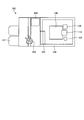
- FIG. 1 is a block diagram illustrating an example of a configuration of an X-ray inspection system including a control device according to the first embodiment.
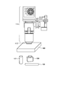
- FIG. 2 is a diagram illustrating an example of the configuration of the X-ray inspection system according to the first embodiment.
- FIG. 3 is a diagram illustrating an example of the configuration of the X-ray inspection system according to the first embodiment.
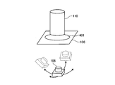
- FIG. 4 is a conceptual diagram showing an example of the configuration of the X-ray tube in the first embodiment.
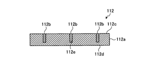
- FIG. 5 is a diagram for explaining a cross-sectional configuration of the X-ray generation target according to the first embodiment.
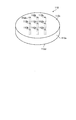
- FIG. 6 is an exploded perspective view of the target for X-ray generation in the first embodiment.
- FIG. 1 is a block diagram illustrating an example of a configuration of an X-ray inspection system including a control device according to the first embodiment.
- FIG. 2 is a diagram illustrating an example of the configuration of the X-ray inspection system according to the first embodiment.
- FIG. 3 is
- FIG. 7 is a diagram illustrating an example of information stored in the target position table according to the first embodiment.
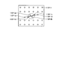
- FIG. 8 is a diagram illustrating a case where the X-ray nano target is included in the electron beam irradiation range and a case where the X-ray nano target is not included in the electron beam irradiation range in the first embodiment.
- FIG. 9 is a diagram illustrating an example of processing performed by the specifying unit according to the first embodiment.
- FIG. 10 is a diagram illustrating an example of processing performed by the specifying unit in the first embodiment.
- FIG. 11 is a diagram illustrating the position of the nano target for X-ray generation specified by the position information in the first embodiment.
- FIG. 12 is a flowchart illustrating an example of a flow of target position table creation processing by the control device according to the first embodiment.
- FIG. 13 is a block diagram illustrating an example of a configuration of an X-ray inspection system including a control device according to the second embodiment.
- FIG. 14 is a diagram illustrating an example of a relationship among an X generation nanotarget having an X-ray nanotarget, a sample stage, and a camera according to the second embodiment.
- FIG. 15 is a diagram illustrating an example of a relationship among an X generation nanotarget having an X-ray nanotarget, a sample stage, and a camera according to the second embodiment.
- FIG. 13 is a block diagram illustrating an example of a configuration of an X-ray inspection system including a control device according to the second embodiment.
- FIG. 14 is a diagram illustrating an example of a relationship among an X generation nanotarget having an X-ray nanotarget, a sample stage, and a camera according to the second embodiment.
- FIG. 16 is a diagram illustrating an example of the case where the X-ray nano target is positioned at the center of the range imaged by the camera according to the second embodiment.
- FIG. 17 is a diagram illustrating an example of the case where the X-ray nano target is located in the periphery of the range imaged by the camera according to the second embodiment.
- FIG. 18 is a diagram illustrating an example of information stored in the difference image table according to the second embodiment.
- FIG. 19 is a diagram illustrating the tilt angle in the second embodiment.
- FIG. 20 is a flowchart illustrating an example of a flow of processing for adjusting the irradiation position of the electron beam in the second embodiment.
- FIG. 21 is a block diagram illustrating an example of a configuration of an X-ray inspection system including a control device according to the third embodiment.
- FIG. 22 is a diagram illustrating an example of an X generation target according to the third embodiment.
- FIG. 23 is a diagram illustrating an example of an X generation target according to the third embodiment.
- FIG. 24 is a diagram illustrating an example of information stored in the target position table according to the third embodiment.
- FIG. 25 is a flowchart illustrating an example of a flow of an X-ray nanotarget switching process in the third embodiment.
- FIG. 26 is a diagram illustrating an example of an embodiment of an X-ray generation target.
- FIG. 27 is a diagram illustrating an example of an embodiment of an X-ray generation target.
- FIG. 22 is a diagram illustrating an example of an X generation target according to the third embodiment.
- FIG. 23 is a diagram illustrating an example of an X generation target according to the third embodiment.
- FIG. 24 is a
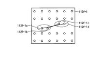
- FIG. 28 is a diagram illustrating an example of identifying the second X-ray nanotarget using the first X-ray nanotarget.
- FIG. 29 is a diagram illustrating an example of identifying a second X-ray nanotarget using the first X-ray nanotarget.
- FIG. 30 is a diagram illustrating an example of identifying a second X-ray nanotarget using the first X-ray nanotarget.
- FIG. 31 is a diagram illustrating an example of the switching order of the X-ray nanotargets.
- the X-ray inspection system is provided on an X-ray inspection apparatus that generates X-rays from an X-ray nanotarget by irradiating an electron beam with an electron beam irradiation unit, and a substrate.
- a target position storage unit that stores position information indicating the position of the X-ray nano target
- an electron beam irradiation unit of the X-ray inspection apparatus irradiates an electron beam to the position stored in the target position storage unit
- a control device having an irradiation control unit to control.
- the X-ray inspection system is, for example, in one embodiment, the substrate is provided with a plurality of X-ray nano targets, and the target position storage unit includes a plurality of the X-ray nano targets. The position information is stored for each.
- the control device controls the electron beam irradiation unit so as to scan the substrate with an electron beam.
- the X-ray inspection system according to the first embodiment includes reflected electrons reflected from the substrate among the electrons included in the electron beam, X-rays generated from the X-ray nano target by irradiation of the electron beam, and electrons.
- An acquisition unit is further provided for acquiring irradiation information that is at least one of target currents generated from the substrate by beam irradiation.
- the X-ray inspection system further includes a specifying unit that specifies position information where the X-ray nano target is located on the substrate based on the irradiation information acquired by the acquiring unit.
- the X-ray inspection system further includes a storage unit that stores the position information specified by the specifying unit in the target position storage unit.
- the specifying unit creates image information of the substrate based on the irradiation information, and the image information
- the position information is obtained. Identify.
- the X-ray inspection system in 1st Embodiment is the electron used when the said target position storage part specified the said positional information for every said X-ray nano target in one Embodiment, for example.
- the beam irradiation conditions are further stored.
- the storage unit stores the position information and the irradiation condition in the target position storage unit.
- the target position storage unit stores XY coordinates on the irradiation surface of the substrate irradiated with the electron beam as the position information. To do.
- the control method reads the position information from the target position storage unit that stores position information indicating the position of the X-ray nano target provided on the substrate, An irradiation control step of controlling the electron beam irradiation unit of the X-ray inspection apparatus to irradiate the electron beam to the position indicated by the position information read by the reading step.
- control program is a reading procedure for reading position information from a target position storage unit that stores position information indicating the position of an X-ray nano target provided on a substrate;
- An irradiation control procedure for controlling the electron beam irradiation unit of the X-ray inspection apparatus to irradiate the electron beam to the position indicated by the position information read by the reading procedure and the computer are executed.
- control device is stored in the target position storage unit that stores position information indicating the position of the X-ray nano target provided on the substrate, and the target position storage unit. And an irradiation control unit that controls the electron beam irradiation unit of the X-ray inspection apparatus to irradiate the electron beam with respect to the position.
- FIG. 1 is a block diagram illustrating an example of a configuration of an X-ray inspection system including a control device according to the first embodiment.
- the X-ray inspection system 10 includes an X-ray inspection apparatus 100 and a control apparatus 200.
- FIGS. 2 and 3 are diagrams showing an example of the configuration of the X-ray inspection system according to the first embodiment.
- X-rays are generated from the X-ray nano target 112b by the electron beam irradiation unit 111 irradiating the X-ray generation target 112 having the X-ray nano target 112b with an electron beam.
- the X-ray inspection apparatus 100 is used for confirming whether a three-dimensional structure is appropriately formed by a three-dimensional high integration technique. To explain with a more detailed example, it is used to inspect the shape of TSV (Through Silicon Via, through silicon via) and the presence or absence of defects.
- TSV Three Silicon Via, through silicon via
- the present invention is not limited to this, and may be used to inspect an arbitrary object.
- the inspection by the X-ray inspection apparatus 100 is a nondestructive inspection.
- a case where the inspection target by the X-ray inspection apparatus 100 is a substrate will be described as an example.
- the present invention is not limited to this, and any sample may be the inspection target.
- the X-ray inspection apparatus 100 includes a load port 101 into which a substrate to be inspected is loaded from the outside, and a wafer robot 102 that places the substrate loaded into the load port 101 on a notch aligner 103.
- the X-ray inspection apparatus 100 includes an X-ray tube 110 that includes an electron beam irradiation unit 111 and an X-ray generation target 112 and irradiates X-rays. Further, the X-ray inspection apparatus 100 includes a sample stage 106 on which a substrate carried from the wafer door 105 into the X-ray inspection chamber is placed. The X-ray inspection apparatus 100 generates reflected electrons reflected on the inner substrate of electrons contained in the electron beam, X-rays generated from the X-ray nano target 112b by the electron beam irradiation, and generated from the substrate by the electron beam irradiation. The detector 107 detects at least one of the target currents.
- the X-ray inspection apparatus 100 includes an X-ray camera 108 that detects X-rays. For example, when the detector 107 detects an X-ray dose, the detector 107 is disposed within the X-ray generation radiation angle generated by the X-ray nano target 112 b below the sample stage 106. A metallic cylindrical cover for excluding extraneous X-rays coming from other than the X-ray nano target 112b may be further installed on the detector 107.
- the extraneous X-rays are, for example, Compton scattering and X-rays derived from cosmic rays.
- the X-ray inspection apparatus 100 further includes a camera stage 109 for moving the X-ray camera 108.
- the X-ray inspection apparatus 100 when the X-ray tube 110 emits X-rays, the X-ray camera 108 detects X-rays that have passed through the substrate placed on the sample stage 106.
- the configuration of the X-ray inspection apparatus 100 shown in FIG. 2 is merely an example, and the present invention is not limited to this.
- the X-ray inspection apparatus 100 includes an optical microscope that acquires an optical image of a substrate placed on the X-ray examination room or the sample stage 106, and IR information on the substrate placed on the X-ray examination room or the sample stage 106.
- FIG. 4 is a conceptual diagram showing an example of the configuration of the X-ray tube in the first embodiment.
- the electron beam irradiation unit 111 of the X-ray tube 110 includes a filament 111a that generates heat and generates an electron beam by supplying power, an anode 111b, a scan coil 111c, a condenser lens 111d, and an aperture 111e.
- the filament 111a is a cathode of a thermionic gun using thermionic emission.
- the anode 111b is one of the electrodes of the electron gun.
- the anode 111b applies a positive high voltage to the cathode and accelerates electrons.
- the scan coil 111c is a coil for scanning the electron beam to a certain position of the nano target.
- the condenser lens 111d is a lens placed between the electron gun and the objective lens.
- the aperture 111e narrows the electron source image narrowed down by the condenser lens 111d to a certain constant.
- the alignment coil 111f is a coil for changing the aperture width of the aperture 111e.
- the objective lens 111g is a lens that adjusts the focal length with respect to the X-ray nano target.
- the objective lens 111g is used for optimizing the X-ray irradiation conditions by changing the current passed through the coil forming the objective lens 111g and performing focusing with the nano target.
- the aperture 111h objective lens stop
- FIG. 5 is a diagram for explaining a cross-sectional configuration of the X-ray generation target in the first embodiment.
- FIG. 6 is an exploded perspective view of the X-ray generation target according to the first embodiment.
- the X-ray generation target 112 includes a substrate 112a and an X-ray nano target 112b.
- the X-ray generation target 112 shown in FIGS. 5 and 6 is an example, and the present invention is not limited to this.
- the substrate 112a is made of, for example, diamond and is formed into a disk shape.
- the substrate 112a has one irradiation surface 112c on the plate surface and a back surface 112d on the opposite side of the plate surface.
- the substrate 112a is not limited to a disc shape, and may be formed in other shapes, for example, a square plate shape.
- the thickness of the substrate 112a is set to about 100 ⁇ m, for example.
- the outer diameter of the substrate 112a is set to about 3 mm, for example.
- a bottomed hole 112e is formed on the substrate 112a from the irradiation surface 112c side.
- the hole 112e has an inner space formed by a bottom surface and a side wall surface.
- the inner space of the hole 112e is formed in a cylindrical body shape, for example.
- the inner space of the hole 112e is not limited to a cylindrical body shape, and may be an arbitrary shape such as a prismatic body shape.
- the inner diameter of the hole 112e is set to about 100 nm, for example.
- the depth of the hole 112e is set to about 1 ⁇ m, for example.
- the hole 112e is formed so that the hole diameter is small and the aspect ratio of the hole is large.
- the X-ray nano target 112b is disposed in the hole 112e formed in the substrate 112a.
- the X-ray nano target 112b is made of metal and has a cylindrical shape corresponding to the inner space of the hole 112e. Examples of the metal constituting the X-ray nano target 112b include copper, tungsten, gold, and platinum.
- the X-ray nano target 112b is formed corresponding to the shape of the inner space of the hole 112e.
- the axial length of the columnar shape is, for example, about 1 ⁇ m.
- the length of the cylindrical shape in the radial direction is, for example, about 100 nm.
- the case where nine X-ray nano targets 112b are provided is shown as an example, but the present invention is not limited to this, and the number of X-ray nano targets 112b may be arbitrary.
- control device 200 includes an input / output unit 201, a storage unit 210, and a control unit 220.
- the control device 200 is connected to the X-ray inspection apparatus 100 and controls the X-ray inspection apparatus 100 as described in detail below.
- the input / output unit 201 is connected to the control unit 220.
- the input / output unit 201 includes, for example, a keyboard, a mouse, a microphone, and the like, receives information and instructions from the user, and inputs the received information and instructions to the control unit 220.
- the input / output unit 201 includes an output device such as a display and a speaker, and outputs information to the user.
- the input / output unit 201 transmits and receives information to and from the control device 200. The details of information and instructions input or output by the input / output unit 201 are not described here, and will be described together with description of each related unit.
- the storage unit 210 is connected to the control unit 220.
- the storage unit 210 stores data used for various processes performed by the control unit 220.
- the storage unit 210 is, for example, a semiconductor memory device such as a RAM (Random Access Memory), a ROM (Read Only Memory), or a flash memory (Flash Memory), or a hard disk or an optical disk.
- the storage unit 210 includes a target position table 211.
- the target position table 211 stores position information indicating the position of the X-ray nano target 112b provided on the substrate 112a. Specifically, the target position table 211 stores position information for each of a plurality of X-ray nano targets 112b. For example, the target position table 211 stores XY coordinates on the irradiation surface 112c of the substrate 112a irradiated with the electron beam as position information. To explain with a more detailed example, the target position table 211 stores XY coordinates starting from a predetermined location on the substrate 112a as position information.
- the target position table 211 further stores the electron beam irradiation conditions used when specifying the position information for each of the plurality of X-ray nano targets 112b.
- the target position table 211 includes an alignment value, a focus value, a tube current / voltage value, an X as an irradiation condition used when the X-ray tube 110 irradiates an electron beam when acquiring position information as described later. Stores the radiation dose value and the cumulative irradiation time.
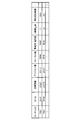
- FIG. 7 is a diagram illustrating an example of information stored in the target position table according to the first embodiment.
- the target position table 211 includes “target ID” which is identification information for uniquely identifying the X-ray generation target 112 and the substrate 112 a of the X-ray generation target 112 identified by the target ID.
- “Nano target ID”, which is identification information for uniquely identifying each of the provided X-ray nano targets 112b, “position information”, and “irradiation conditions” are stored in association with each other.
- “alignment value”, “focus value”, “tube current / voltage value”, “X-ray dose value”, and “irradiation cumulative time” are stored as irradiation conditions. The case of doing is shown as an example.
- the target position table 211 stores, for example, the target ID “T001”, the nano target ID “NT01”, and the position information “2.5 ( ⁇ m), 2.5 ( ⁇ m)” in association with each other. Further, as irradiation conditions, alignment values “2.5 (V), 1.3 (V)”, focus value “10000 (au)”, tube current / voltage value “50 (kV), 60 (kV) ”, the X-ray dose value“ 1.1 (au) ”, and the cumulative irradiation time“ 122.5 (h) ”are stored in association with each other.
- the target position table 211 indicates that the X-ray nano target 112b specified by the nano target ID “NT01” provided for the target ID “T001” has position information “2.5 ( ⁇ m), 2.5 ( ⁇ m)”. Is stored at the position specified by “”. Further, in the target position table 211, the position information “2.5 ( ⁇ m), 2.5 ( ⁇ m)” of the X-ray nano target 112b specified by the nano target ID “NT01” is the alignment value “2.5 ( V), 1.3 (V) ", a focus value" 10000 (au) ", a tube current / voltage value” 50 (kV), 60 (kV) ", and an X-ray dose value" 1.
- the target position table 211 indicates that the position information “2.5 ( ⁇ m), 2.5 ( ⁇ m)” of the X-ray nano target 112b specified by the nano target ID “NT01” is irradiated with an electron beam X It is stored that the cumulative time of irradiation with the line is “122.5 (h)”.
- the coordinate information on the substrate 112a of the X-ray generation target 112 is stored as the position information.
- the present invention is not limited to this.
- any information may be stored as long as the information can uniquely identify the position on the substrate 112a.
- the control unit 220 is connected to the input / output unit 201.
- the control unit 220 includes an internal memory that stores a program that defines various processing procedures and the like, and controls various processes.
- the control unit 220 is, for example, an application specific integrated circuit (ASIC), a field programmable gate array (FPGA), a central processing unit (CPU), or a micro processing unit (MPU).
- ASIC application specific integrated circuit
- FPGA field programmable gate array
- CPU central processing unit
- MPU micro processing unit
- the control unit 220 includes an acquisition unit 221, a specification unit 222, a storage unit 223, and an irradiation control unit 224.
- the acquisition unit 221 controls the electron beam irradiation unit 111 so as to scan the substrate 112a with an electron beam, and the X-ray nano target is irradiated with the reflected electrons reflected on the inner substrate 112a of the electrons contained in the electron beam and the electron beam irradiation.
- Irradiation information which is information about at least one of the X-rays generated from 112b and the target current generated from the substrate 112a by electron beam irradiation, is acquired.
- the acquisition unit 221 acquires irradiation information by controlling the X-ray inspection apparatus 100. For example, the acquisition unit 221 acquires the reflected electrons and target current detected by the detector 107 from the detector 107 of the X-ray inspection apparatus 100. In other words, the acquisition unit 221 acquires irradiation information by acquiring the X-ray dose measured by the detector 107. Here, the acquisition unit 221 acquires the irradiation information associated with the position of the irradiation surface 112c for the entire irradiation surface 112c of the X-ray generation target 112.
- the present invention is not limited to this, and when it is possible to limit the range where the inner X-ray nano target 112b of the irradiation surface 112c is provided, a part of the irradiation surface 112c is selectively irradiated. Information may be acquired.
- the acquisition unit 221 transmits an irradiation condition that the electron beam irradiation unit 111 of the X-ray inspection apparatus 100 irradiates an electron beam to the X-ray inspection apparatus 100, and then the X-ray generation target 112 is sent to the X-ray inspection apparatus 100. After scanning the surface, irradiation information as a scanning result is acquired.
- the specifying unit 222 specifies the position information where the X-ray nano target 112b is located on the substrate 112a based on the irradiation information acquired by the acquiring unit 221. That is, in the substrate 112a, the amount of electrons reflected from the X-ray nano target 112b is larger than the amount of electrons reflected from other portions. Further, X-rays generated by irradiation with an electron beam have a larger X-ray dose generated from the X-ray nano target 112b than an X-ray dose generated in other portions. Further, the target current generated by electron beam irradiation has a smaller target current value as the atomic number increases, and the target current value increases as the atomic number decreases.
- the target current generated from the X-ray nano target 112b It becomes smaller than the target current generated. Based on this, there is a difference in irradiation information between when the X-ray nano target 112b is included in the electron beam irradiation range and when the X-ray nano target 112b is not included in the electron beam irradiation range. Become. Based on this, the specifying unit 222 specifies the position of the X-ray nano target 112b based on the detection result of the irradiation information.
- FIG. 8 is a diagram illustrating a case where an X-ray nano target is included in the electron beam irradiation range and a case where an X-ray nano target is not included in the electron beam irradiation range in the first embodiment.
- the acquisition unit 221 acquires irradiation information when the electron beam is irradiated to the X-ray nano target 112b. become.
- the X-ray nano target 112b is provided at an interval of 40 ⁇ m, and the diameter of the irradiation range of the electron beam is 10 ⁇ m.
- the region 301 is centered on the X-ray nano target 112b.
- the present invention is not limited to this.
- the specifying unit 222 creates image information of the substrate 112a based on the irradiation information. Then, the specifying unit 222 identifies an X-ray nano target range indicating an irradiation position where the X-ray nano target 112b in the region scanned on the substrate 112a is irradiated with an electron beam in the image information. And the specific
- FIG. 9 to 10 are diagrams illustrating an example of processing performed by the specifying unit according to the first embodiment.
- the specifying unit 222 creates image information based on the irradiation information acquired from the detector 107, for example.
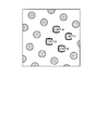
- FIG. 9 is an example of an EB absorption electron image image using the target current created by the specifying unit 222 in the first embodiment.
- the density of each region of image information differs depending on the magnitude of the value obtained as the irradiation information.
- specification part 222 detects the area
- FIG. 10 is a diagram illustrating an example of identification processing of the center coordinates by the specifying unit according to the first embodiment.
- the specifying unit 222 specifies position information by identifying the center coordinates 302 in the region 301.
- the specifying unit 222 detects the plurality of regions 301 and identifies the center coordinates for each detected region.
- the specifying unit 222 specifies position information for each of the plurality of X-ray nano targets 112b.
- the specifying unit 222 identifies the center coordinates after performing image processing for correcting the distortion. Further, the electron density in the electron beam irradiation range is lower in the peripheral part than in the central part. As a result, there is a difference in the value obtained as irradiation information between the case where the X-ray nano target 112b is located at the center of the electron beam and the case where the X-ray nano target 112b is located at the periphery.
- the specifying unit 222 increases the contrast in the region 301 and then determines the irradiation information in the region 301.
- the position information of the X-ray nano target 112b may be detected using the size.
- the storage unit 223 stores the position information specified by the specifying unit 222 in the target position table 211. Specifically, the storage unit 223 stores position information and irradiation conditions in the target position table 211. For example, the storage unit 223 stores the irradiation information transmitted to the X-ray inspection apparatus 100 by the acquisition unit 221 in association with the center coordinates identified by the specifying unit 222 in the target position table 211. In this case, the storage unit 223 associates arbitrary identification information for specifying the X-ray generation target 112 with arbitrary identification information for identifying the detected X-ray nano target 112b, and stores positional information. Store with.
- the storage unit 223 includes a target ID “T001”, a nano target ID “NT01”, and position information “2.5 ( ⁇ m), 2.5 ( ⁇ m)”. Further, the alignment values “2.5 (V), 1.3 (V)”, the focus value “10000 (au)”, the tube current / voltage are stored as the irradiation conditions. The values “50 (kV), 60 (kV)”, the X-ray dose value “1.1 (a.u.)”, and the cumulative irradiation time “122.5 (h)” are stored in association with each other.
- the acquisition unit 221 transmits the irradiation condition to the X-ray inspection apparatus 100 has been described as an example.
- the present invention is not limited to this, and the arbitrary irradiation condition in the X-ray inspection apparatus 100 is described.
- the acquisition unit 221 may acquire the irradiation conditions used by the X-ray inspection apparatus 100. Details of the processing performed by the acquisition unit 221, the specifying unit 222, and the storage unit 223 will be described later with reference to flowcharts, and thus the description thereof is omitted here.
- the irradiation control unit 224 controls the electron beam irradiation unit 111 of the X-ray inspection apparatus 100 to irradiate the electron beam to the position stored in the target position table 211. Specifically, when irradiating X-rays, the irradiation control unit 224 selects one nanotarget ID associated with the identification information of the X-ray generation target 112 set in the X-ray tube, The position information associated with the selected nano target ID is acquired. Then, the electron beam is irradiated from the electron beam irradiation unit 111 of the X-ray tube 110 so that the acquired position information becomes a focus, and X-rays are generated toward the sample stage 106 from the X-ray nano target 112b.
- FIG. 11 is a diagram showing the position of the target for X-ray generation specified by the position information in the first embodiment.
- the image information created by the specifying unit 222 and the position specified by the position information are shown superimposed.
- the position of each X-ray nano target 112b is specified by each of a plurality of pieces of position information. For example, in the example shown in FIG. 11, nano target IDs “NT11” to “NT14” are shown.
- the irradiation control unit 224 controls the electron beam irradiation unit 111 to irradiate the electron beam to the position stored in the target position table 211, so that the X-ray nano target 112b is irradiated with the electron beam, and the X-ray X-rays are generated from the nano target 112b.
- control device 200 may be any information processing device such as a known personal computer, workstation, smartphone, or tablet terminal. Specifically, it may be realized by mounting the functions of the control unit 220 and the storage unit 210 of FIG. The control device 200 may be integrated with the X-ray inspection apparatus 100. Further, a part of the configuration of the control device 200 may be connected as a separate device via an arbitrary network.
- the position information is detected and stored in the target position table 211, and then the position alignment is performed using the stored position information.
- the position information may be stored in the target position table 211 in advance.
- the acquisition unit 221, the specification unit 222, and the storage unit 223 may not be included in the configuration described above.
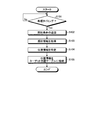
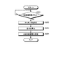
- FIG. 12 is a flowchart illustrating an example of a flow of target position table creation processing by the control device according to the first embodiment.
- the acquisition unit 221 transmits irradiation conditions for the electron beam irradiation unit 111 to irradiate an electron beam to the X-ray inspection apparatus 100 (Step S102). . Thereafter, the acquisition unit 221 acquires irradiation information from the X-ray inspection apparatus 100 (step S103). For example, the acquisition unit 221 acquires the reflected electrons and the target current detected by the detector 107 for the entire irradiation surface 112 c of the X-ray generation target 112.
- specification part 222 specifies position information based on the irradiation information acquired by the acquisition part 221 (step S104). For example, the specifying unit 222 creates image information having different densities based on the magnitude of the value obtained as the irradiation information, based on the irradiation information acquired from the detector 107. And the specific
- the storage unit 223 stores the position information specified by the specifying unit 222 in the target position table 211 (step S105).
- the storage unit 223 stores a target ID “T001”, a nano target ID “NT01”, and positional information “2.5 ( ⁇ m), 2.5 ( ⁇ m)” in association with each other, and further performs irradiation.
- alignment values “2.5 (V), 1.3 (V)”, focus value “10000 (au)”, tube current / voltage values “50 (kV), 60 (kV)” ”, The X-ray dose value“ 1.1 (a.u.) ”, and the cumulative irradiation time“ 122.5 (h) ” are stored in association with each other.
- the acquisition unit 221 has exemplified the case where the irradiation condition is transmitted to the X-ray inspection apparatus 100, but is not limited thereto, and without transmitting the irradiation condition, Irradiation conditions set in advance or determined each time in the X-ray inspection apparatus 100 may be used.
- the control apparatus 200 also acquires the irradiation conditions from the X-ray inspection apparatus 100 at an arbitrary time.
- Position information may be acquired. Further, for example, after identifying the center coordinates of the detected area 301, the specifying unit 222 enlarges and displays an area in an arbitrary range around the center coordinates, and positions based on the difference in irradiation information in the enlarged display area. Information may be specified, or the coordinates of the center may be specified as position information.
- the high resolution is achieved by accelerating electrons with a high voltage (for example, about 50 to 150 keV) and, for example, a fine focus on an X-ray nano target in which a metal is provided on the entire surface of the substrate. You can get it by focusing on.
- X-rays so-called bremsstrahlung X-rays, are generated when electrons lose energy in the target.
- the focal spot size is substantially determined by the size of the irradiated electron beam.
- the electron beam may be converged to a small spot.
- the amount of electrons may be increased.
- the spot size of the electron beam and the amount of current are in a contradictory relationship, and a large current cannot flow through a small spot. If a large current is passed through a small spot, the X-ray nano target may be easily consumed due to heat generation.
- the electron beam is irradiated with a high acceleration voltage (for example, about 50 to 150 keV), and near the X-ray nano target 112b.
- a high acceleration voltage for example, about 50 to 150 keV
- the X-ray focal diameter does not expand, and degradation of resolution can be suppressed.
- a resolution uniquely determined by the size of the X-ray nano target 112b can be obtained.
- the X-ray generation target 112 includes the substrate 112a made of diamond and the X-ray nano target 112b, the X-ray generation target 112 is extremely excellent in heat dissipation. The consumption of the target 112 can be prevented.
- the control device 200 includes the target position table 211 that stores position information indicating the position of the X-ray nano target 112b provided on the substrate 112a, and the position stored in the target position table 211.
- the electron beam irradiation unit 111 of the X-ray inspection apparatus 100 has an irradiation control unit 224 that controls the electron beam irradiation. As a result, the X-ray inspection can be performed by quickly and easily irradiating the electron beam onto the X-ray nano target 112b provided on the substrate 112a.
- the diameter of the X-ray nano target 112b is smaller than the electron beam irradiation range.
- the electron density of the electron beam may be higher in the central part than in the peripheral part in the electron beam irradiation range.
- the positional information of the X-ray nano target 112b is stored, and the X-ray nano target 112b is placed at the center of the irradiation range of the electron beam by irradiating the stored position with the electron beam.
- X-rays can be irradiated, the amount of X-ray generation can be maximized, and X-ray inspection can be performed quickly and easily.
- the substrate 112a is provided with a plurality of X-ray nano targets 112b, and the target position table 211 stores position information for each of the plurality of X-ray nano targets 112b.
- the X-ray inspection can be performed by irradiating the substrate 112a with a plurality of X-ray nano targets 112b quickly and easily, and can be easily switched to another X-ray nano target 112b. It becomes possible.
- 112 a includes a specifying unit 222 that specifies position information where the X-ray nano target 112 b is located, and a storage unit 223 that stores the position information specified by the specifying unit 222 in the target position table 211.
- the specifying unit 222 creates image information of the substrate 112a based on the irradiation information, and an electron beam is applied to the X-ray nano target 112b in the region scanned on the substrate 112a in the image information.
- the position information is specified by identifying the X-ray nano target range indicating the irradiation position irradiated with and identifying the center position of the X-ray nano target range.
- the target position table 211 further stores the electron beam irradiation conditions used when specifying the position information for each of the plurality of X-ray nanotargets 112b. Position information and irradiation conditions are stored in the target position table 211. As a result, when performing the X-ray inspection, it is possible to select and use an appropriate X-ray nano target 112b according to the inspection purpose.
- the X-ray inspection system includes an X-ray inspection apparatus that generates X-rays from an X-ray nano target when an electron beam irradiation unit irradiates an electron beam. Further, the X-ray inspection system in the second embodiment is photographed by the electron beam irradiation unit of the X-ray inspection apparatus irradiating the X-ray nano target with the electron beam and irradiating the X-ray nano target with the X-ray.
- the difference calculation unit calculates the difference between the position information indicating the center in the X-ray image and the position information indicating the position where the X-ray nano target is located in the vertical direction in the X-ray image; And a control device having a position adjusting unit that adjusts the X-ray inspection apparatus in a direction to eliminate the difference.
- the difference calculation unit stores an X-ray image or a simulation image obtained in a situation where there is the difference for each of the plurality of differences.
- the difference is calculated by referring to the unit and matching the photographed X-ray image with the X-ray image or simulation image stored in the storage unit.
- the X-ray inspection system according to the second embodiment further includes a creation unit that creates the simulation image for each difference.
- the difference calculation unit calculates a difference by performing matching with each of the simulation images created by the creation unit.
- the X-ray inspection system includes, for example, in one embodiment, the X-ray inspection apparatus includes an X-ray camera as a detection unit that detects X-rays irradiated from the X-ray nanotarget.
- the position adjusting unit adjusts the X-ray inspection apparatus by controlling to change at least one of the position of the X-ray camera and the tilt angle of the X-ray camera.
- the difference calculation unit uses coordinates in the X-ray image as the position information.
- control method in the second embodiment is that, in one embodiment, the electron beam irradiation unit of the X-ray inspection apparatus irradiates the X-ray nano target with an electron beam and irradiates the X-ray nano target with X-rays.
- a difference calculating step for calculating a difference between position information indicating a center in the photographed X-ray image and position information indicating a position where the X-ray nano target is located in the vertical direction in the X-ray image; and the difference calculating step.
- control program in the second embodiment is such that an electron beam irradiation unit of an X-ray inspection apparatus irradiates an X-ray nano target with an electron beam and irradiates the X-ray nano target with X-rays.
- a position adjustment procedure for adjusting the X-ray inspection apparatus in a direction to eliminate the calculated difference is executed by the computer.
- control device is such that an electron beam irradiation unit of an X-ray inspection apparatus irradiates an X-ray nanotarget with an electron beam and irradiates the X-ray nanotarget with X-rays.
- a difference calculating unit that calculates a difference between position information indicating a center in the photographed X-ray image and position information indicating a position where the X-ray nano target is located in a vertical direction in the X-ray image; and the difference calculating unit
- a position adjustment unit that adjusts the X-ray inspection apparatus in a direction to eliminate the calculated difference.
- FIG. 13 is a block diagram illustrating an example of a configuration of an X-ray inspection system including a control device according to the second embodiment.
- the storage unit 210 further includes a difference image table 212
- the control unit 220 includes a simulation image creation unit 225 and a difference calculation.
- the part 226 and the position adjustment part 227 were further provided was shown as an example, it is not limited to this.
- some or all of the units included in the storage unit 210 and the control unit 220 in the first embodiment may not be included in a range where no contradiction occurs.
- the control device 200 has a difference image table 212 in the storage unit 210.
- the difference image table 212 stores an X-ray image or a simulation image obtained in a situation where there is a difference for each of a plurality of differences.
- the difference is an X-ray image captured by the electron beam irradiation unit 111 of the X-ray inspection apparatus 100 irradiating the X-ray nano target 112b with an electron beam and irradiating the X-ray nano target 112b with X-rays.
- the difference between the position information indicating the center of the X-ray and the position information indicating the position where the X-ray nano target 112b is in the vertical direction in the X-ray image is shown.
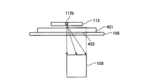
- FIG. 14 and FIG. 15 are diagrams illustrating an example of a relationship among an X generation target having an X-ray nano target, a sample stage, and a camera according to the second embodiment.
- FIG. 14 the case where the X-ray nano target 112b is located at the center of the range imaged by the X-ray camera 108 is shown.
- FIG. 14 The case where the X-ray nano target 112b is located in FIG. That is, in the example illustrated in FIG.
- the X-ray nano target 112 b is positioned on the position corresponding to the center of the range 402 of the X-ray image captured by the X-ray camera 108 and on the vertical line of the substrate 401.
- the X-ray nano target 112 b is positioned on a position corresponding to the periphery of the range 403 of the X-ray image captured by the X-ray camera 108 and on the vertical line of the substrate 401.
- the substrate 401 is described as being provided with a plurality of holes in the vertical direction.
- FIG. 16 is a diagram illustrating an example of the case where the X-ray nano target 112b is positioned at the center of the range captured by the camera according to the second embodiment.
- the X-ray nano target 112 b is positioned on the position corresponding to the center of the range 402 of the X-ray image captured by the X-ray camera 108 and the vertical line of the substrate 401, the center of the X-ray image is displayed.
- the X-rays enter the substrate 401 from the X-ray nano target 112b in the vertical direction.
- the X-rays are incident on the substrate 401 with a deviation from the vertical direction, that is, with an angle.
- the direction in which the hole is provided coincides with the incident direction of the X-ray.
- An image corresponding to a hole in the surface is obtained.
- the direction in which the hole is provided does not match the incident direction of the X-ray, and the angle is perpendicular to the vertical direction, that is, in an oblique direction.
- an image corresponding to the wall surface or bottom of the hole is shown off the hole on the irradiation surface of the substrate 401.
- FIG. 17 is a diagram illustrating an example of the case where the X-ray nano target is located in the periphery of the range imaged by the camera according to the second embodiment.
- FIG. 17 when there is a position corresponding to the X-ray nano target 112b in the peripheral part, an image corresponding to the hole in the irradiation surface of the substrate 401 is obtained for the hole 405 of the substrate 401 in the peripheral part.
- the other holes deviate from the image corresponding to the holes on the irradiation surface of the substrate 401, and an image corresponding to the wall surface and bottom of the holes is displayed.
- FIG. 18 is a diagram illustrating an example of information stored in the difference image table according to the second embodiment.
- the difference image table 212 stores images in association with differences.
- “difference” indicating a difference type and “difference value” indicating a difference value are stored as differences.
- it is blank, but it is assumed that image data is stored in association with the difference.
- the difference image table 212 stores a type “coordinate difference”, a difference “1 ⁇ m, 0 ⁇ m”, and an image in association with each other. That is, the difference image table 212 is an X-ray image obtained when there is a position corresponding to the X-ray nano target 112b at a position shifted by 1 ⁇ m on the x-axis and 0 ⁇ m on the y-axis from the center coordinates of the X-ray image.
- the simulation image is stored in association with the type “coordinate difference” and the difference “1 ⁇ m, 0 ⁇ m”.
- the difference image table 212 stores a type “tilt angle difference”, a difference “1 degree, 0 degree”, and an image in association with each other. That is, the difference image table 212 indicates that the type of “tilt angle difference” is used for an X-ray image or a simulation image obtained when the tilt angle is shifted by 1 degree on the x axis and 0 degree on the y axis with respect to the vertical direction. And the difference “1 degree, 0 degree”.
- an image may be stored in association with a combination of a coordinate difference and a tilt angle difference, and one of the coordinate difference and the tilt angle difference may not be used.
- the difference value any value may be used as long as the difference can be uniquely specified.
- FIG. 19 is a diagram illustrating the tilt angle in the second embodiment.
- the X-ray camera 108 is provided so that the tilt angle can be changed.
- the tilt angle difference indicates, for example, a shift on the basis of the vertical direction, and is indicated as an angle on the X axis and the Y axis that are arbitrarily set.
- the control unit 220 further includes a simulation image creation unit 225, a difference calculation unit 226, and a position adjustment unit 227.
- the simulation image creation unit 225 creates a simulation image for each difference.
- the simulation image may be created by any method. In the following, a case where the control unit 220 includes the simulation image creation unit 225 will be described as an example. However, the present invention is not limited to this, and the simulation image creation unit 225 may not be provided.
- the difference calculation unit 226 is a center in an X-ray image captured by the electron beam irradiation unit of the X-ray inspection apparatus 100 irradiating the X-ray nano target 112b with an electron beam and irradiating the X-ray nano target 112b with X-rays. And the position information indicating the position where the X-ray nano target 112b is present in the vertical direction in the X-ray image is calculated.
- the difference calculation unit 226 stores an X-ray image or a simulation image obtained in a situation where there is a difference for each of a plurality of differences. , The difference is calculated by matching the photographed X-ray image with the X-ray image or simulation image stored in the difference image table 212.
- the difference calculation unit 226 refers to the difference image table 212 to select one image that is closest to the captured X-ray image, and sets the difference associated with the selected image as the difference image table. By obtaining from 212, the difference is calculated.
- the difference calculation unit 226 calculates a value indicating the degree of matching between the captured image and the matched image, and plots the value in association with the difference associated with the matched image. You may do it.
- the difference calculation unit 226 may identify the point having the highest score after plotting each image stored in the difference image table 212 and calculate the difference corresponding to the identified point. . Further, the difference calculation unit 226 may use part or all of the images stored in the difference image table 212.
- the difference image table 212 includes a difference associated with an image read out from the difference image table 212 and an image to be read out next. The accuracy of the difference to be calculated may be adjusted by increasing or decreasing the difference from the associated difference.
- the position adjustment unit 227 adjusts the X-ray inspection apparatus 100 in a direction to eliminate the difference calculated by the difference calculation unit 226. Specifically, the position adjustment unit 227 controls to change at least one of the position of the X-ray camera 108 and the tilt angle of the X-ray camera 108. For example, the position adjustment unit 227 changes the position of the X-ray camera 108 and the camera tilt angle by the same amount as the difference acquired from the difference image table 212 by the difference calculation unit 226.
- the position adjustment unit 227 moves the position of the X-ray camera 108 by “ ⁇ 1 ⁇ m, 0 ⁇ m”. The difference is eliminated by adjusting so as to. Further, for example, when the combination of the type “tilt angle difference” and the difference “1 degree, 0 degree” is calculated by the difference calculation unit 226, the position adjustment unit 227 sets the tilt angle of the X-ray camera 108 to “ The difference is eliminated by adjusting to move “-1 degree, 0 degree”.
- the difference elimination method described above is an example, and the present invention is not limited to this.
- the difference may be eliminated by moving the moving stage together or independently. Since an example of detailed processing by the difference calculation unit 226 and the position adjustment unit 227 described above will be described later, description thereof is omitted here.
- FIG. 20 is a flowchart illustrating an example of a flow of processing for adjusting the irradiation position of the electron beam in the second embodiment.
- the difference X image table 212 is referred to and stored in the acquired X-ray image and the difference image table 212.
- Matching with the X-ray image or simulation image being performed is performed (step S202).
- the difference calculation unit 226 performs matching with the captured X-ray image for each of the images stored in the difference image table 212. Then, the difference calculation unit 226 selects one image that is the most approximate, and acquires the difference associated with the selected image from the difference image table 212, thereby calculating the difference (step S203).
- the position adjustment unit 227 adjusts the X-ray inspection apparatus 100 in a direction to eliminate the difference calculated by the difference calculation unit 226 (step S204). For example, when the combination of the type “coordinate difference” and the difference “1 ⁇ m, 0 ⁇ m” is calculated by the difference calculation unit 226, the position adjustment unit 227 moves the position of the X-ray camera 108 by “ ⁇ 1 ⁇ m, 0 ⁇ m”. The difference is eliminated by adjusting so as to.
- the control device 200 causes the electron beam irradiation unit of the X-ray inspection apparatus 100 to irradiate the X-ray nano target 112b with an electron beam, and the X-ray nano target 112b.
- a difference calculation unit 226 that calculates a difference between position information indicating a center in an X-ray image captured by irradiating X-rays and position information indicating a position where the X-ray nano target 112b is present in the vertical direction in the X-ray image.
- a position adjustment unit 227 that adjusts the X-ray inspection apparatus 100 in a direction to eliminate the difference calculated by the difference calculation unit 226.
- control can be performed so that X-rays are emitted from the center of the X-ray image.
- the difference calculation unit 226 refers to the difference image table 212 that stores an X-ray image or a simulation image obtained in a situation where there is a difference for each of a plurality of differences. Then, the difference is calculated by matching the photographed X-ray image with the X-ray image or simulation image stored in the storage unit. As a result, the difference can be reliably calculated.
- the simulation image creating unit 225 that creates a simulation image for each difference is further provided, and the difference calculating unit 226 is a pre-simulation created by the simulation image creating unit 225.
- the difference is calculated by matching with each image. As a result, the difference can be reliably calculated.
- the X-ray inspection apparatus 100 includes the X-ray camera, and the position adjustment unit 227 calculates the position of the X-ray camera and the tilt angle of the X-ray camera.
- the X-ray inspection apparatus 100 is adjusted by controlling to change at least one of them. As a result, the adjustment can be performed easily and with high accuracy.
- an X-ray generation target 112 includes a substrate 112a, a plurality of first X-ray nanotargets 112f having a first size provided on the substrate 112a, and a first X-ray among the substrates 112a.
- a second X-ray nanotarget 112g provided at a position specified by the line nanotarget 112f and having a second size smaller than the first size is provided.
- the X-ray nano targets 112f-1, 112f-2, 112f-1a to 1d, 112f-2a, and 112f-2b are collectively referred to as an X-ray nano target 112f.
- the target 112 for X-ray generation is specified by a plurality of first X-ray nano targets 112f and a plurality of first X-ray nano targets 112f on the substrate 112a.
- a plurality of X-ray nanotarget groups 112h including the first X-ray nanotarget 112g are provided.
- a plurality of X-ray nanotarget groups are arranged on the substrate 112a. Further, the first X-ray nanotargets 112f are shared by the adjacent X-ray nanotarget groups 112h between the first X-ray nanotargets 112g included in the adjacent X-ray nanotarget groups 112h. Provided in the form.
- a plurality of X-ray nanotarget groups 112h are arranged in a lattice pattern on the substrate 112a.
- the first X-ray nanotarget 112f has a plurality of sizes, and the first X-ray nanotarget 112f having a different size is provided for each arrangement direction of the X-ray nanotarget group 112h.
- the substrate 112a is provided with identification information for identifying the X-ray nano target group 112h.
- the X-ray inspection apparatus 100 that generates X-rays from the X-ray nanotarget by the electron beam irradiation unit 111 irradiating the electron beam, and the control apparatus 200 that controls the X-ray inspection apparatus 100. And have.
- the control device 200 is specified by the substrate 112a, a plurality of first X-ray nanotargets 112f having a first size provided on the substrate 112a, and the first X-ray nanotarget 112f among the substrates 112a.
- the irradiation control unit acquires X-ray images of the same sample before and after switching when the X-ray nano target switching unit switches the X-ray nano target.
- control device 200 compares the X-ray images acquired by the irradiation control unit, and the irradiation condition of the electron beam by the irradiation control unit based on the comparison result by the comparison unit. And an adjusting unit for adjusting.
- the comparison part was image
- the difference between the position information indicating the center in the X-ray image and the position information indicating the position of the X-ray nano target in the vertical direction in the X-ray image is calculated, and the adjustment unit eliminates the difference calculated by the comparison unit
- the X-ray inspection apparatus 100 is adjusted in the direction.
- the control device 200 includes the substrate 112a, a plurality of first X-ray nano targets 112f having a first size provided on the substrate 112a, and the first X-ray of the substrate 112a.
- the irradiation control unit that controls the electron beam irradiation unit 111 of the apparatus to irradiate the electron beam and the X-ray nano target irradiated with the electron beam by the irradiation control unit, the X for the same sample before and after switching
- An X-ray image acquisition unit that acquires a line image.
- the control method includes the substrate 112a, the first X-ray nano target 112f having a first size provided on the substrate 112a, and the first X-ray nano of the substrate 112a.
- the control program includes a substrate 112a, a plurality of first X-ray nano targets 112f having a first size provided on the substrate 112a, and a first X-ray nano of the substrate 112a.
- the computer executes an X-ray image acquisition procedure for acquiring an image.
- FIG. 21 is a block diagram illustrating an example of a configuration of an X-ray inspection system including a control device according to the third embodiment.
- the control unit 220 further includes an irradiation control unit 224 a, a comparison unit 228, and an adjustment unit 229.
- the irradiation control unit 224a is also referred to as an X-ray nano target switching unit or an X-ray image acquisition unit.
- the X-ray generation target 112 in the third embodiment will be further described.
- FIG. 22 is a diagram illustrating an example of an X generation target according to the third embodiment.
- the target 112 for X-ray generation includes a first X-ray nano target 112f having a first size provided on the substrate 112a, and a first of the substrates 112a.
- a second X-ray nano target 112g provided at a position specified by the X-ray nano target 112f and having a second size smaller than the first size.
- the case where the X-ray generation target 112 has two different sizes as the first X-ray nanotarget 112f is shown as an example. That is, the X-ray generation target 112 includes two first X-ray nanotargets 112f-1 and two first X-ray nanotargets 112f- smaller in size than the first X-ray nanotarget 112f-1. 2 is shown as an example. However, the X-ray generation target 112 is not limited to this, and a plurality of X-ray nano targets 112f may be all the same size. Further, in the case where the X-ray nano targets 112f have different sizes, the number for each size may be an arbitrary number.
- the second X-ray nanotarget 112g is provided between the two first X-ray nanotargets 112f-1 or between the two first X-ray nanotargets 112f-2.
- the interval at which the X-ray nanotargets are provided may be any distance, and the number of the second X-ray nanotargets 112g provided may also be arbitrary.
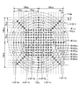
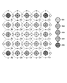
- FIG. 23 is a diagram illustrating an example of an X generation target according to the third embodiment.
- the target 112 for X-ray generation includes a plurality of first X-ray nano targets 112f and second X-rays specified by a plurality of first X-ray nano targets 112f on a substrate 112a.
- a plurality of X-ray nanotarget groups 112h including the nanotarget 112g may be provided.
- the distance between the X-ray nano targets described in FIG. 23 is an example, and is not limited to this, and may be an arbitrary value.
- the substrate 112a may be provided with identification information 112i for identifying the X-ray nanotarget group 112h.
- the identification information 112i may be arbitrary information, for example, an alphabet, a number, an arbitrary symbol, or the like.
- the first X-ray nanotarget 112f is the second X-ray nanotarget 112g included in each of the adjacent X-ray nanotarget groups 112h. Between each, you may provide in the form shared by each adjacent X-ray nano target group 112h.
- the case where a plurality of X-ray nanotarget groups 112h are arranged on the substrate 112a is shown as an example, but the present invention is not limited to this.
- the first X-ray nanotarget 112f has a plurality of sizes, and the first X-ray nanotarget 112f having a different size is arranged for each arrangement direction of the X-ray nanotarget group 112h.
- the present invention is not limited to this.
- sequence state shown in FIG. 23 is an example, Comprising: It is not limited to this, Arbitrary arrangement
- FIG. 24 is a diagram illustrating an example of information stored in the target position table according to the third embodiment.
- the target position table 211 a includes “usage state” indicating the use state of the X-ray nano target 112 and irradiation used when an X-ray image is captured in addition to the various types of information illustrated in FIG. 7.
- An “irradiation condition” indicating a condition and an “image information” indicating an X-ray image photographed using the associated X-ray nano target are stored.
- FIG. 21 an example in which irradiation conditions and image information are stored for “before switching” and “after switching” is shown as an example.
- the target position table 211 a associates the usage state “completed”, the irradiation condition “...”, And the image information “image A” with the target ID “T001”.
- the target position table 211a has been used for the target ID “T001”, and “image” is captured as an image taken with the X-ray nano target with the target ID “T001” using the irradiation condition “... A "is stored.
- the irradiation control unit 224a includes a substrate 112a, a plurality of first X-ray nanotargets 112f having a first size provided on the substrate 112a, and the first of the substrates 112a.
- the electron beam irradiation unit 111 of the X-ray inspection apparatus 100 is controlled to emit an electron beam.
- the irradiation control unit 224a switches the X-ray nano target based on the positional relationship between the first X-ray nano target 112f and / or the second X-ray nano target 112g. For example, when irradiating X-rays, the irradiation controller 224a selects one nanotarget ID associated with the identification information of the X-ray generation target 112 set in the X-ray tube, and selects the selected nano The position information associated with the target ID is acquired.
- the irradiation control unit 224a can identify the first X-ray nano target 112f identified by using an enlargement magnification capable of identifying the first X-ray nano target 112f, and can identify the second X-ray nano target 112g.
- the second X-ray nano target 112g provided at the position specified by the position of the identified first X-ray nano target 112f is moved to the position of the identified first X-ray nano target 112f using a large magnification. Identify based on.
- the irradiation control unit 224a directs the X-rays from the X-ray nano target 112b to the sample stage 106 so that the second X-ray nano target 112g identified at the position corresponding to the target position table 211 is in focus. To generate.
- the irradiation control unit 224a acquires X-ray images of the same sample before and after switching.
- An arbitrary method may be used as the method for acquiring the X-ray image, and the description thereof is omitted.
- the irradiation control unit 224a stores irradiation information and image information regarding the corresponding X-ray nano target in the target position table 211a before and after switching.
- the comparison unit 228 compares the X-ray images acquired by the irradiation control unit 224a. For example, like the difference calculation unit 226, the comparison unit 228 allows the electron beam irradiation unit 111 of the X-ray inspection apparatus 100 to irradiate the X-ray nano target with an electron beam and irradiate the X-ray nano target with X-rays. A difference between position information indicating the center in the captured X-ray image and position information indicating a position where the X-ray nano target is located in the vertical direction in the X-ray image is calculated.
- the adjustment unit 229 adjusts the irradiation condition of the electron beam by the irradiation control unit 224 based on the comparison result by the comparison unit 228. For example, the adjustment unit 229 adjusts the X-ray inspection apparatus 100 in a direction in which the difference calculated by the comparison unit 228 is eliminated, similarly to the position adjustment unit 227.
- FIG. 25 is a flowchart illustrating an example of a flow of an X-ray nanotarget switching process in the third embodiment.
- the irradiation control unit 224a acquires the current X-ray irradiation condition, stores it in the target position table 211a (Step S302), and captures an X-ray image.
- the use state is updated to “completed” (step S304).
- the irradiation control unit 224a uses the current X-ray nano target information as a switching source of the target ID “T001” as the current information.
- the irradiation conditions used are stored, the photographed X-ray image is stored, and the use state is updated to “completed”.
- the irradiation control unit 224a selects the next target ID and switches to the X-ray nano target identified by the target ID (step S305). For example, the irradiation control unit 224a uses the positional information stored in the target position table 211a and the positional relationship between the first X-ray nano target 112f and the second X-ray nano target 112g to switch the X-ray nano after switching. Switch target.
- the irradiation control unit 224a switches based on the position information stored in the target position table 211a, and then, based on the positional relationship between the first X-ray nano target 112f and the second X-ray nano target 112g, By using different absorption current images with different magnifications, it is possible to check whether the focus is on or to adjust the irradiation conditions.
- the irradiation control part 224a acquires the X-ray image about the same sample before and behind switching (step S306). For example, when the switching is completed, the irradiation control unit 224a captures an X-ray image of the same sample as before the switching after the switching. For example, in the control unit 28, the irradiation control unit 224a acquires the current X-ray irradiation condition and stores it in the target position table 211a (step S307), captures an X-ray image, and stores it in the target position table 211a. (Step S308), the use state is updated to “in use” (Step S309).
- the irradiation control unit 224a when switching to the X-ray nano target 112 identified by the target ID “T002”, the irradiation control unit 224a currently uses the information as the X-ray nano target that is the switching destination of the target ID “T002”. Current irradiation conditions are stored, the photographed X-ray image is stored, and the use state is updated to “in use”.
- the comparison unit 228 compares the X-ray images acquired by the irradiation control unit 224a (step S310), and the adjustment unit 229 performs irradiation of the electron beam by the irradiation control unit 224 based on the comparison result by the comparison unit 228.
- the conditions are adjusted (step S311). For example, like the difference calculation unit 226 and the position adjustment unit 227 of the second embodiment, the comparison unit 228 calculates the difference, and the adjustment unit 229 adjusts the position.
- the X-ray generation target 112 includes the substrate 112a, a plurality of first X-ray nanotargets 112f having a first size provided on the substrate 112a, and the substrate 112a. And a second X-ray nano target 112g provided at a position specified by the first X-ray nano target 112f and having a second size smaller than the first size. As a result, it is possible to easily align with the X-ray nano target.
- the X-ray nano target has a lifetime and needs to be replaced every certain time. For example, assuming that the lifetime of the X-ray nano target is 300 hours, when performing a continuous inspection, the X-ray nano target irradiated with the electron beam is replaced every 12 days.
- the second X-ray nano target 112g is provided at a position specified by the first X-ray nano target 112f, so that the first X-ray nano target 112f can be identified. First, the first X-ray nano target 112f is identified, and then the smaller second X-ray nano target 112g is identified based on the position of the identified first X-ray nano target 112f. It becomes possible.
- the second X-ray nanotarget 112g can be identified quickly, and further, the position of the second X-ray nanotarget 112g can be specified with high accuracy.
- the switching process when the switching process is performed manually, for example, it is considered that the electron beam is gradually brought closer to a fine part while viewing the absorption current image, and the skill level is required of the operator.
- the switching process when it is performed manually, not only the time cost and labor cost are incurred, but also there is a possibility that it becomes an obstacle to realizing high reproducibility of the apparatus.
- the switching process can be easily automated, and the switching process is performed. Highly accurate and reliable execution is possible.
- a plurality of X-ray nanotarget groups 112h are provided on the substrate 112a.
- the substrate provided with the X-ray nano target can be used for a long time.
- other X-ray nano target groups 112h may be formed by the same method. And the X-ray nano target can be efficiently formed and identified.
- a plurality of X-ray nanotarget groups are arranged on the substrate 112a, and the first X-ray nanotarget 112f is included in each of the adjacent X-ray nanotarget groups 112h.
- the two X-ray nanotargets 112g are provided so as to be shared by the adjacent X-ray nanotarget groups 112h.
- the second X-ray nanotarget 112g is larger in size than the first X-ray nanotarget 112f, and the second X-ray nanotarget 112g is used when acquiring a high-resolution image.
- the one X-ray nano target 112f is used as a marker for specifying the second X-ray nano target 112g.
- the first X-ray nanotarget 112f is shared by a plurality of different X-ray nanotarget groups 112h, thereby reducing the number of the first X-ray nanotargets 112f while reducing the number of the first X-ray nanotargets 112f.
- the X-ray nano target 112g can be easily specified. Further, since the first X-ray nano target 112f is itself an X-ray nano target, it can also be used to obtain an X-ray image.
- the second X-ray nanotarget 112g when acquiring a high-resolution / high-resolution X-ray image, the second X-ray nanotarget 112g is used, and when acquiring a low-resolution X-ray image, the first X-ray nanotarget 112f is used. Can be used.
- a plurality of X-ray nanotarget groups 112h are arranged on the substrate 112a, and the first X-ray nanotarget 112f has a plurality of sizes, and the X-ray nanotarget group A first X-ray nano target 112f having a different size is provided for each arrangement direction of 112h.
- the substrate 112a it is possible to easily align the substrate 112a while disposing many nano targets.
- the substrate 112a is provided with identification information 112i for identifying the X-ray nanotarget group 112h.
- identification information 112i for identifying the X-ray nanotarget group 112h.
- the X-ray inspection apparatus 100 that generates X-rays from the X-ray nanotarget by the electron beam irradiation unit 111 irradiating the electron beam, and the control for controlling the X-ray inspection apparatus 100.
- the control device 200 is specified by the substrate 112a, the first X-ray nano target 112f having a first size provided on the substrate 112a, and the first X-ray nano target 112f of the substrate 112a. Electron beam irradiation of the X-ray inspection apparatus 100 to an X-ray generation target 112 having a second X-ray nano target 112g having a second size smaller than the first size.
- the unit 111 is controlled to emit an electron beam.
- the control device 200 switches the X-ray nano target based on the positional relationship between the first X-ray nano target 112f and / or the second X-ray nano target 112g. As a result, the X-ray nano target can be automatically switched.
- the control device 200 acquires X-ray images of the same sample before and after switching. As a result, quality before and after switching can be ensured.
- the state of X-rays irradiated from the X-ray nano target may change before and after switching by changing the irradiation position of the electron beam or moving the substrate. There is. Based on this, by capturing X-ray images of the same sample before and after switching, adjustment can be performed so that the same X-ray image can be captured before and after switching.
- control device 200 compares the X-ray images acquired by the X-ray image acquisition unit and adjusts the irradiation condition of the electron beam by the irradiation control unit 224 based on the comparison result. To do. As a result, quality before and after switching can be ensured.
- the comparison unit 228 causes the electron beam irradiation unit 111 of the X-ray inspection apparatus 100 to irradiate the X-ray nano target with an electron beam and irradiate the X-ray nano target with X-rays.
- the difference between the position information indicating the center in the X-ray image photographed in step 1 and the position information indicating the position of the X-ray nano target in the vertical direction in the X-ray image is calculated.
- the adjustment unit 229 adjusts the X-ray inspection apparatus 100 in a direction to eliminate the difference calculated by the difference calculation unit 226.
- the X-ray generation target, the inspection system, the control device, the control method, and the control program according to the first to third embodiments have been described.
- the present invention is not limited thereto, and various In the embodiment, an X-ray generation target, an inspection system, a control device, a control method, and a control program may be realized.
- the embodiments may be appropriately combined as long as the processing contents do not contradict each other, and the embodiments may be executed independently.
- the X-ray generation target 112 having the X-ray nano target 112b has been described as an example.
- the present invention is not limited to this.
- a target may be used.
- the diameter of the target provided on the X-ray generation target 112 may be larger than the diameter of the electron beam, or a metal may be provided on the entire surface of the X-ray generation target 112 and used as the target.
- the X-ray nanotarget is not limited to the embodiment mentioned in the above-described embodiment, and any X-ray nanotarget may be used.
- the X-ray generation target may be provided with an arbitrary number of X-ray nanotargets, and the arrangement of the X-ray nanotargets may be arbitrary.
- FIG. 26 is a diagram illustrating an example of an embodiment of an X-ray generation target.
- the X-ray generation target 112 may be provided with an X-ray nano target only in a partial region of the substrate 112a.
- one or a plurality of X-ray nano targets may be provided only in the region 112j including the center in the substrate 112a.
- the region 112j of the substrate 112a is provided with, for example, the X-ray nanotarget shown in FIGS. 6, 22 and 23, and the region other than the region 112j is provided with the X-ray nanotarget. Absent.
- FIG. 27 is a diagram illustrating an example of an embodiment of an X-ray generation target.
- the X-ray generation target 112 may be an X-ray nano target as shown in FIG.
- the X-ray generation target 112 shown in FIG. 27 includes a first X-ray nanotarget 112f-1, a first X-ray nanotarget 112f-2, a second X-ray nanotarget 112g, Have
- the second X-ray nanotarget 112g is provided at a position identified by the first X-ray nanotarget 112f-1 or the first X-ray nanotarget 112f-2.
- FIG. 27 is a diagram illustrating an example of an embodiment of an X-ray generation target.
- the X-ray generation target 112 may be an X-ray nano target as shown in FIG.
- the X-ray generation target 112 shown in FIG. 27 includes a first X-ray nanotarget 112f-1, a first X-ray nanotarget 112f-2, a second X
- the second X-ray nanotarget 112g includes a straight line connecting the first X-ray nanotarget 112f-1a and the first X-ray nanotarget 112f-1c,
- the first X-ray nano target 112f-1b and the first X-ray nano target 112f-1d are located at the intersection of the straight line connecting the first X-ray nano target 112f-1b and the first X-ray nano target 112f-1d.
- 112f-2b is located on a straight line.
- an example of the distance between each X-ray nano target is described, but this is only an example and the present invention is not limited to this.
- FIG. 28 to FIG. 30 are diagrams showing an example of identifying the second X-ray nanotarget using the first X-ray nanotarget. For example, first, as shown in FIG. 28, by looking at the X-ray generation target 112 shown in FIG. 27 using a low magnification within a range in which the first X-ray nanotarget 112f-1 can be identified, One X-ray nano target 112f-1 is identified. Then, for example, as shown in FIG.
- the control device 200 the first X-ray nano target 112f-1a and the straight line connecting the first X-ray nano target 112f-1c and the first X-ray nano target 112f
- the position of the second X-ray nanotarget 112g is limited. Thereafter, as shown in FIG.
- the control device 200 increases the magnification to a magnification at which the first X-ray nanotarget 112f-2 can be identified, and then the first X-ray nanotarget 112f-2a and b, a straight line connecting the first X-ray nano target 112f-1a and the first X-ray nano target 112f-1c, and the first X-ray nano target 112f-1b and the first X-ray nano target
- the position of the X-ray nano target 112g is further limited, and the position of the second X-ray nano target 112g is specified.
- first X-ray nanotargets 112f-1a to 112d are special.
- any method may be used.
- a pattern of the first X-ray nano target 112f-1 is held in advance, and patterns corresponding to the first X-ray nano targets 112f-1a to d are identified by pattern matching, whereby the first X-ray nano target 112f-1 is identified.
- the line nanotargets 112f-1a-d may be identified.
- the X-ray images acquired before and after switching may be stored in the database in association with the identification information of the X-ray nanotargets before and after switching.
- the control device 200 may keep the X-ray image for later adjustment.
- the X-ray nano target switching process may be executed at an arbitrary timing.
- the total time during which the electron beam is irradiated after the start of use may be measured, and may be exchanged when an arbitrary time is reached or by an instruction from the user.
- the irradiation control unit 224a compares an X-ray nano target that can be irradiated with an irradiation condition with a small electron beam deflection angle with an X-ray nano target that can be irradiated with an irradiation condition with a large electron beam deflection angle. Then, the selection may be preferentially performed, and the selected X-ray nano target may be switched. As a result, measurement can be resumed more quickly than when switching to an X-ray nanotarget that can be irradiated under irradiation conditions with a large deflection angle of the electron beam.
- FIG. 31 is a diagram showing an example of the switching order of the X-ray nano targets.
- the X-ray nanotargets are switched in the order of the X-ray nanotarget group 501 to the X-ray nanotarget group 504 among the plurality of X-ray nanotarget groups. That is, the X-ray nano target is switched so as to spread in the radial direction from the center. In this way, the change angle and the amount of movement of the electron beam before and after switching can be reduced.
- a plurality of X-ray nanotarget groups are provided and the X-ray nanotargets are switched for each X-ray nanotarget group.
- the present invention is not limited to this. is not.
- the electron beam is not applied to the X-ray nano target group 112h but to each X-ray nano target.
- X-ray nanotargets that can be irradiated under irradiation conditions with a small deflection angle may be switched with priority.
- the image quality adjustment of the X-ray image may be performed after the X-ray nano target is switched.
- the X-ray inspection apparatus 100 or the control apparatus 200 may perform image quality adjustment processing for reducing the noise amount of the X-ray image after switching.
- the X-ray inspection apparatus 100 and the control apparatus 200 perform image quality adjustment processing for reducing the amount of noise included in the X-ray image based on the X-ray image obtained after the switching.
- the image quality adjustment process itself for reducing the amount of noise may provide a known method, for example, may be executed by adjusting one or both of the tube current and the tube voltage, You may perform by adjusting arbitrary parameters.
- the X-ray inspection apparatus 100 and the control apparatus 200 store a threshold value for the noise amount of the image in advance, determine whether the noise amount of the X-ray image captured after switching exceeds the threshold value, and determine that it exceeds the threshold value. In such a case, image quality adjustment processing may be performed. Further, the X-ray inspection apparatus 100 and the control apparatus 200 are not limited to the case where the noise amount of the image is used as the threshold value, and arbitrary information may be used. For example, the X-ray inspection apparatus 100 or the control apparatus 200 may hold and use one or a plurality of combinations among the mode value, minimum value, maximum value, and average value in the histogram of the X-ray image as the threshold value. good.
- the image quality adjustment described above may be executed in combination with any of the above-described embodiments, or may be executed alone.
- the X-ray image quality adjustment processing after switching may be executed in conjunction with acquiring X-ray images of the same sample before and after switching.
- the X-ray nano target 112 has individual differences, and there is a possibility that quality variations of X-ray images due to individual differences of the X-ray nano target before and after switching. Based on this, after switching, for example, by adjusting one or both of the tube current and tube voltage, the quality of the image quality is adjusted based on the X-ray image. In addition, X-ray images of the same quality can be taken. Further, for example, the X-ray inspection apparatus 100 or the control apparatus 200 automatically executes image quality adjustment processing, so that manual adjustment can be omitted, inspection quality can be maintained constant, and maintenance costs and running costs are reduced. Can also be realized.
- the target position table 211a further stores “irradiation conditions” and “image information” is shown as an example.
- the present invention is not limited to this.
- a table provided separately from the target position table 211a may store “irradiation conditions” and “image information”.
- the target position table 211a further stores “irradiation conditions” and “image information” is shown as an example.
- image information may be stored without storing “irradiation conditions”.
- each component of each illustrated apparatus is functionally conceptual and does not necessarily need to be physically configured as illustrated. That is, the specific form of distribution / integration of each device is not limited to the one shown in the figure, and all or a part of the distribution / integration may be functionally or physically distributed in arbitrary units according to various loads or usage conditions. Can be integrated and configured.
- some or all of the tables stored in the storage unit of the control device 200 may be stored in a database provided separately from the control device 200.
- the control device 200 reads and writes information by accessing the database via an arbitrary network, for example.
- the difference calculation unit 226 and the comparison unit 228 may be integrated, or the position adjustment unit 227 and the adjustment unit 229 may be integrated.
Landscapes
- Physics & Mathematics (AREA)
- Health & Medical Sciences (AREA)
- Life Sciences & Earth Sciences (AREA)
- Chemical & Material Sciences (AREA)
- Analytical Chemistry (AREA)
- Biochemistry (AREA)
- General Health & Medical Sciences (AREA)
- General Physics & Mathematics (AREA)
- Immunology (AREA)
- Pathology (AREA)
- Analysing Materials By The Use Of Radiation (AREA)
Abstract
X線発生用ターゲット(112)は、実施形態の一例において、基板を備える。また、X線発生用ターゲットは、実施形態の一例において、基板に複数設けられる第1の大きさを有する第1のX線ナノターゲット(112f)を備える。また、X線発生用ターゲットは、実施形態の一例において、基板の内第1のX線ナノターゲット(112f)により特定される位置に設けられ、第1の大きさよりも小さい第2の大きさを有する第2のX線ナノターゲット(112g)とを備える。
Description
本発明の種々の側面及び実施形態は、X線発生用ターゲット、検査システム、制御装置、制御方法及び制御プログラムに関する。
X線検査装置は、X線非破壊検査など様々な分野で用いられている。X線検査装置は、電子を出射するフィラメント部と、フィラメント部から出射された電子が照射されるX線発生用ターゲットとを備える。X線検査装置は、フィラメント部から出射された電子をX線発生用ターゲットに衝突させることで、X線を外部に照射する。
ここで、基板と、基板に埋設されたターゲット部とを備えるX線発生用ナノターゲットが考えられる。例えば、X線発生用ナノターゲットは、イオンビーム(Focused Ion Beam:FIB)加工装置を用いてイオンビームを基板に照射してスパッタすることで、基板に有底状の穴を形成される。そして、X線発生用ナノターゲットは、基板の穴付近にX線発生用ターゲットの材料ガスを流しながら基板の穴にイオンビームを照射することで、穴に金属を堆積させてターゲット部を形成される。
しかしながら、X線発生用ナノターゲットを用いて高分解能非破壊透過像による検査を行うX線検査装置は、未だ実用されていない。
開示するX線発生用ターゲットは、1つの実施形態において、基板と、前記基板に複数設けられる第1の大きさを有する第1のX線ナノターゲットと、前記基板の内前記第1のX線ナノターゲットにより特定される位置に設けられ、前記第1の大きさよりも小さい第2の大きさを有する第2のX線ナノターゲットとを備える。
開示するX線検査システムの1つの態様によれば、検査対象物のX線像を適切に取得することが可能となる。
以下に、開示するX線発生用ターゲット、検査システム、制御装置、制御方法及び制御プログラムの実施形態について、図面に基づいて詳細に説明する。なお、本実施形態により開示する発明が限定されるものではない。各実施形態は、処理内容を矛盾させない範囲で適宜組み合わせることが可能である。
(第1の実施形態)
第1の実施形態におけるX線検査システムは、1つの実施形態において、電子ビーム照射部が電子ビームを照射することでX線ナノターゲットからX線を発生するX線検査装置と、基板に設けられたX線ナノターゲットの位置を示す位置情報を記憶するターゲット位置記憶部と、前記ターゲット位置記憶部に記憶された位置に対してX線検査装置の電子ビーム照射部が電子ビームを照射するように制御する照射制御部とを有する制御装置とを備える。
第1の実施形態におけるX線検査システムは、1つの実施形態において、電子ビーム照射部が電子ビームを照射することでX線ナノターゲットからX線を発生するX線検査装置と、基板に設けられたX線ナノターゲットの位置を示す位置情報を記憶するターゲット位置記憶部と、前記ターゲット位置記憶部に記憶された位置に対してX線検査装置の電子ビーム照射部が電子ビームを照射するように制御する照射制御部とを有する制御装置とを備える。
また、第1の実施形態におけるX線検査システムは、例えば、1つの実施形態において、前記基板には複数のX線ナノターゲットが設けられ、前記ターゲット位置記憶部は、複数ある前記X線ナノターゲット各々について前記位置情報を記憶する。
また、第1の実施形態におけるX線検査システムは、例えば、1つの実施形態において、前記制御装置は、前記基板を電子ビームで走査するように前記電子ビーム照射部を制御する。また、第1の実施形態におけるX線検査システムは、前記電子ビームに含まれる電子の内前記基板において反射した反射電子と、電子ビームの照射により前記X線ナノターゲットから発生したX線と、電子ビームの照射により前記基板から発生したターゲット電流との内、少なくとも1つである照射情報を取得する取得部を更に備える。また、第1の実施形態におけるX線検査システムは、前記取得部により取得された照射情報に基づいて、前記基板において前記X線ナノターゲットが位置する位置情報を特定する特定部を更に備える。また、第1の実施形態におけるX線検査システムは、前記特定部により特定された位置情報を前記ターゲット位置記憶部に格納する格納部を更に備える。
また、第1の実施形態におけるX線検査システムは、例えば、1つの実施形態において、前記特定部は、前記照射情報に基づいて前記基板の画像情報を作成し、該画像情報において、前記基板において走査された領域の内前記X線ナノターゲットに電子ビームが照射された照射位置を示すX線ナノターゲット範囲を識別し、該X線ナノターゲット範囲の中心位置を識別することで、前記位置情報を特定する。
また、第1の実施形態におけるX線検査システムは、例えば、1つの実施形態において、前記ターゲット位置記憶部は、複数ある前記X線ナノターゲットごとに、前記位置情報を特定する際に用いた電子ビームの照射条件を更に記憶する。また、第1の実施形態におけるX線検査システムでは、前記格納部は、前記位置情報と前記照射条件とを前記ターゲット位置記憶部に格納する。
また、第1の実施形態におけるX線検査システムは、例えば、1つの実施形態において、前記ターゲット位置記憶部は、前記電子ビームが照射される前記基板の照射面におけるXY座標を前記位置情報として記憶する。
また、第1の実施形態における制御方法は、1つの実施形態において、基板に設けられたX線ナノターゲットの位置を示す位置情報を記憶するターゲット位置記憶部から位置情報を読み出す読出工程と、前記読出工程によって読み出された位置情報により示される位置に対して、X線検査装置の電子ビーム照射部が電子ビームを照射するように制御する照射制御工程とを含む。
また、第1の実施形態における制御プログラムは、1つの実施形態において、基板に設けられたX線ナノターゲットの位置を示す位置情報を記憶するターゲット位置記憶部から位置情報を読み出す読出手順と、前記読出手順によって読み出された位置情報により示される位置に対して、X線検査装置の電子ビーム照射部が電子ビームを照射するように制御する照射制御手順とコンピュータに実行させる。
また、第1の実施形態における制御装置は、1つの実施形態において、基板に設けられたX線ナノターゲットの位置を示す位置情報を記憶するターゲット位置記憶部と、前記ターゲット位置記憶部に記憶された位置に対してX線検査装置の電子ビーム照射部が電子ビームを照射するように制御する照射制御部とを備える。
(第1の実施形態に係るX線検査システム)
図1は、第1の実施形態に係る制御装置を含むX線検査システムの構成の一例を示すブロック図である。図1に示すように、X線検査システム10は、X線検査装置100と、制御装置200とを有する。
図1は、第1の実施形態に係る制御装置を含むX線検査システムの構成の一例を示すブロック図である。図1に示すように、X線検査システム10は、X線検査装置100と、制御装置200とを有する。
図2及び図3は、第1の実施形態におけるX線検査システムの構成の一例を示す図である。X線検査装置100では、電子ビーム照射部111がX線ナノターゲット112bを有するX線発生用ターゲット112に電子ビームを照射することでX線ナノターゲット112bからX線が発生する。例えば、X線検査装置100は、3次元高集積化技術により適切に3次元構造が形成されたかを確認するために用いられる。より詳細な一例をあげて説明すると、TSV(Through Silicon Via、シリコン貫通ビア)の形状や欠陥の有無を検査する際に用いられる。ただし、これに限定されるものではなく、任意の対象物を検査するのに用いて良い。なお、X線検査装置100による検査は、非破壊検査である。以下では、X線検査装置100による検査対象が基板である場合を例に説明するが、これに限定されるものではなく、任意のサンプルが検査対象であって良い。
図2に示す例では、X線検査装置100は、外部から検査対象となる基板が搬入されるロードポート101と、ロードポート101に搬入された基板をノッチアライナー103に載置するウエハロボット102と、ウエハロボット102によって載置されたウエハの位置合わせを行うノッチアライナー103と、ノッチアライナー103によって位置合わせが終了した基板を鉛隔壁104によって囲まれているX線検査室内に搬入するためのウエハドア105とを有する。
X線検査装置100は、電子ビーム照射部111とX線発生用ターゲット112とを有してX線を照射するX線管110を有する。また、X線検査装置100は、ウエハドア105からX線検査室内へと搬入された基板が載置されるサンプルステージ106を有する。また、X線検査装置100は、電子ビームに含まれる電子の内基板において反射した反射電子と、電子ビームの照射によりX線ナノターゲット112bから発生したX線と、電子ビームの照射により基板から発生したターゲット電流との内少なくとも1つを検出する検出器107を有する。また、X線検査装置100は、X線を検出するX線カメラ108を有する。例えば、検出器107がX線の線量を検出する場合、サンプルステージ106の下部において、X線ナノターゲット112bにより発生するX線の発生放射角度以内に配置する。検出器107に対して、X線ナノターゲット112b以外からやってくる外来のX線を排除するための金属製の筒状のカバーを更に設置しても良い。外来のX線とは、例えば、コンプトン散乱や、宇宙線起因のX線などである。
図3に示すように、X線検査装置100は、X線カメラ108を移動させるためのカメラステージ109を更に備える。X線検査装置100では、X線管110がX線を照射すると、X線カメラ108が、サンプルステージ106に載置される基板を通過したX線を検出する。
なお、図2に示すX線検査装置100の構成は、あくまで一例であり、これに限定されるものではない。例えば、X線検査装置100は、X線検査室内やサンプルステージ106に載置された基板の光学映像を取得する光学顕微鏡と、X線検査室内やサンプルステージ106に載置された基板のIR情報を取得するIR(Infrared Spectroscopy)センサとの内一方又は両方を有しても良い。
図4は、第1の実施形態におけるX線管の構成の一例を示す概念図である。図4に示すように、X線管110の電子ビーム照射部111は、電力供給により発熱して電子ビームを発生するフィラメント111aと、アノード111bと、スキャンコイル111cと、コンデンサレンズ111dと、アパーチャ111eと、アライメントコイル111fと、対物レンズ111gと、アパーチャ111hとを有する。
ここで、フィラメント111aは、熱電子放出を利用した熱電子銃の陰極である。フィラメント111aを熱電子銃の陰極として用いることで、ショットキー電子銃を用いる場合と比較してコストの低下や電流安定化をはかることが可能となる。アノード111bは、電子銃の電極の1つである。アノード111bは、陰極に対してプラスの高電圧を印加させ、電子を加速させる。スキャンコイル111cは、電子線をナノターゲットのある位置へ走査させるためのコイルである。コンデンサレンズ111dは、電子銃と対物レンズの間に置かれたレンズである。アパーチャ111eは、コンデンサレンズ111dで絞られた電子源像をある一定に絞り込む。アライメントコイル111fは、アパーチャ111eの絞り幅を変更するためのコイルである。対物レンズ111gは、X線ナノターゲットに対する焦点距離を調節するレンズである。対物レンズ111gは、対物レンズ111gを形成するコイルに流される電流が変化させられてナノターゲットとのピント合わせが行われることで、X線照射条件の最適化に用いられる。アパーチャ111h(対物レンズ絞り)は、対物レンズ111gに入射する電子線の内、光軸近傍の電子線のみを通過させて、それ以外を遮蔽するための絞りである。
図5は、第1の実施形態におけるX線発生用ターゲットの断面構成を説明するための図である。図6は、第1の実施形態に係るX線発生用ターゲットの分解斜視図である。図5及び図6に示す例では、X線発生用ターゲット112は、基板112aと、X線ナノターゲット112bとを有する。なお、図5及び図6に示すX線発生用ターゲット112は一例であり、これに限定されるものではない。
基板112aは、例えば、ダイヤモンドで形成され、円板形状に形成される。基板112aは、板面の一方の照射面112cと、板面の反対側の裏面112dを有する。基板112aは、円板形状に限られず、他の形状、例えば角板形状に形成されていても良い。基板112aの厚みは、例えば、100μm程度に設定される。基板112aの外径は、例えば、3mm程度に設定される。
このように、穴112eがダイヤモンドに形成されることで、X線発生時に生じる熱を効率良く拡散することが可能となり、大きな電流をかけることが可能となる。
図5及び図6に示す例では、基板112aには、照射面112c側から有底状の穴112eが形成される。穴112eは、底面と側壁面とで形成される内側空間を有する。穴112eの内側空間は、例えば、円柱体形状に形成される。ただし、穴112eの内側空間は円柱体形状に限定されるものではなく、角柱体形状など任意の形状であっても良い。穴112eの内径は、例えば、100nm程度に設定される。穴112eの深さは、例えば、1μm程度に設定される。このように、穴112eは、穴径が小さく形成されるとともに、穴のアスペクト比が大きくなるように形成される。
X線ナノターゲット112bは、基板112aに形成されている穴112e内に配置される。X線ナノターゲット112bは、金属で形成され、穴112eの内側空間に対応した円柱体形状に形成される。X線ナノターゲット112bを構成する金属としては、例えば、銅、タングステン、金、白金等である。
X線ナノターゲット112bは、穴112eの内側空間の形状に対応して形成される。円柱形状の軸方向の長さは、例えば、1μm程度となる。円柱形状の径方向の長さは、例えば、100nm程度となる。なお、図6に示す例では、X線ナノターゲット112bが9つ設けられる場合を例に示したが、これに限定されるものではなく、X線ナノターゲット112bの数は任意であって良い。
図1の説明に戻り、制御装置200について説明する。図1に示すように、制御装置200は、入出力部201と、記憶部210と、制御部220とを有する。制御装置200は、以下に詳細に説明するように、X線検査装置100と接続され、X線検査装置100を制御する。
入出力部201は、制御部220と接続される。入出力部201は、例えば、キーボードやマウス、マイクなどを有し、情報や指示を利用者から受け付け、受け付けた情報や指示を制御部220に入力する。また、入出力部201は、ディスプレイやスピーカ等の出力装置を有し、情報を利用者に出力する。また、入出力部201は、制御装置200と情報を送受信する。なお、入出力部201によって入力されたり出力されたりする情報や指示の詳細については、ここでは説明を省略し、関係する各部について説明する際に併せて説明する。
記憶部210は、制御部220と接続される。記憶部210は、制御部220による各種処理に用いるデータを記憶する。記憶部210は、例えば、RAM(Random Access Memory)やROM(Read Only Memory)、フラッシュメモリ(Flash Memory)などの半導体メモリ素子、又は、ハードディスクや光ディスクなどである。図1に示す例では、記憶部210は、ターゲット位置テーブル211を有する。
ターゲット位置テーブル211は、基板112aに設けられたX線ナノターゲット112bの位置を示す位置情報を記憶する。具体的には、ターゲット位置テーブル211は、複数あるX線ナノターゲット112b各々について、位置情報を記憶する。例えば、ターゲット位置テーブル211は、電子ビームが照射される基板112aの照射面112cにおけるXY座標を位置情報として記憶する。より詳細な一例をあげて説明すると、ターゲット位置テーブル211は、基板112aの所定の箇所を起点とするXY座標を位置情報として記憶する。
また、ターゲット位置テーブル211は、複数あるX線ナノターゲット112bごとに、位置情報を特定する際に用いた電子ビームの照射条件を更に記憶する。例えば、ターゲット位置テーブル211は、後述するように位置情報を取得する際にX線管110が電子ビームを照射する際に用いた照射条件として、アライメント値、フォーカス値、管電流・電圧値、X線線量値、照射累計時間を記憶する。
図7は、第1の実施形態におけるターゲット位置テーブルに記憶された情報の一例を示す図である。図7に示す例では、ターゲット位置テーブル211は、X線発生用ターゲット112を一意に識別する識別情報である「ターゲットID」と、ターゲットIDにより識別されるX線発生用ターゲット112の基板112aに設けられたX線ナノターゲット112b各々を一意に識別する識別情報である「ナノターゲットID」と、「位置情報」と、「照射条件」とを対応付けて記憶する。また、図7に示す例では、照射条件として、「アライメント値」と、「フォーカス値」と、「管電流・電圧値」と、「X線線量値」と、「照射累計時間」とを記憶する場合を例に示した。
この場合、ターゲット位置テーブル211は、例えば、ターゲットID「T001」と、ナノターゲットID「NT01」と、位置情報「2.5(μm)、2.5(μm)」とを対応付けて記憶し、更に、照射条件として、アライメント値「2.5(V)、1.3(V)」と、フォーカス値「10000(a.u.)」と、管電流・電圧値「50(kV)、60(kV)」と、X線線量値「1.1(a.u.)」と、照射累計時間「122.5(h)」とを対応付けて記憶する。
すなわち、ターゲット位置テーブル211は、ターゲットID「T001」に設けられたナノターゲットID「NT01」により特定されるX線ナノターゲット112bが、位置情報「2.5(μm)、2.5(μm)」により特定される位置にあることを記憶する。また、ターゲット位置テーブル211は、ナノターゲットID「NT01」により特定されるX線ナノターゲット112bの位置情報「2.5(μm)、2.5(μm)」が、アライメント値「2.5(V)、1.3(V)」と、フォーカス値「10000(a.u.)」と、管電流・電圧値「50(kV)、60(kV)」と、X線線量値「1.1(a.u.)」とが用いられて電子ビームが照射された際に取得されたことを記憶する。また、ターゲット位置テーブル211は、ナノターゲットID「NT01」により特定されるX線ナノターゲット112bの位置情報「2.5(μm)、2.5(μm)」について、電子ビームが照射されたX線を照射した累計時間が「122.5(h)」であることを記憶する。
なお、上述した例では、位置情報として、X線発生用ターゲット112の基板112aにおける座標情報を記憶する場合を例に示したが、これに限定されるものではない。例えば、基板112aにおける位置を一意に特定できる情報であれば、任意の情報を記憶して良い。
制御部220は、入出力部201と接続される。制御部220は、各種の処理手順などを規定したプログラムを記憶する内部メモリを有し、種々の処理を制御する。制御部220は、例えば、ASIC(Application Specific Integrated Circuit)、FPGA(Field Programmable Gate Array)、CPU(Central Processing Unit)、MPU(Micro Processing Unit)などである。図1に示す例では、制御部220は、取得部221と、特定部222と、格納部223と、照射制御部224とを有する。
取得部221は、基板112aを電子ビームで走査するように電子ビーム照射部111を制御し、電子ビームに含まれる電子の内基板112aにおいて反射した反射電子と、電子ビームの照射によりX線ナノターゲット112bから発生したX線と、電子ビームの照射により基板112aから発生したターゲット電流との内、少なくとも1つについての情報である照射情報を取得する。
具体的には、取得部221は、X線検査装置100を制御することで、照射情報を取得する。例えば、取得部221は、検出器107により検出された反射電子やターゲット電流をX線検査装置100の検出器107から取得する。言い換えると、取得部221は、検出器107により計測されたX線の線量を取得することで、照射情報を取得する。ここで、取得部221は、X線発生用ターゲット112の照射面112cの全面について、照射面112cの位置に紐付けられる照射情報それぞれを取得する。ただし、これに限定されるものではなく、照射面112cの内X線ナノターゲット112bが設けられている範囲を限定することが可能な場合には、照射面112cの内一部について選択的に照射情報を取得するようにしても良い。
例えば、取得部221は、X線検査装置100の電子ビーム照射部111が電子ビームを照射する照射条件をX線検査装置100に送信し、その後、X線検査装置100にX線発生用ターゲット112の表面を走査させた上で、走査結果となる照射情報を取得する。
特定部222は、取得部221により取得された照射情報に基づいて、基板112aにおいてX線ナノターゲット112bが位置する位置情報を特定する。すなわち、基板112aにおいて、X線ナノターゲット112bにおいて反射する電子は、他の部分において反射する電子と比較して量が多い。また、電子ビームの照射により発生するX線は、X線ナノターゲット112bから発生したX線量は、他の部分において発生するX線量と比較して大きい。また、電子ビームの照射により発生するターゲット電流は、原子番号が大きくなるほどターゲット電流値は小さく、原子番号が小さいほどターゲット電流値は大きくなる。この結果、基板112aとしてダイヤモンドを用い、X線ナノターゲット112bとしてダイヤモンド、すなわち、炭素よりも原子量の大きくなるタングステンを用いる場合には、X線ナノターゲット112bから発生したターゲット電流は、他の部分において発生するターゲット電流と比較して小さくなる。このことを踏まえ、電子ビームの照射範囲にX線ナノターゲット112bが含まれる場合と、電子ビームの照射範囲にX線ナノターゲット112bが含まれない場合とでは、照射情報に差が発生することになる。このことを踏まえ、特定部222は、照射情報の検出結果に基づいて、X線ナノターゲット112bの位置を特定する。
図8は、第1の実施形態における電子ビームの照射範囲にX線ナノターゲットが含まれる場合と、電子ビームの照射範囲にX線ナノターゲットが含まれない場合とを示す図である。図8に示すように、X線ナノターゲット112bが電子ビームの照射範囲に含まれる領域301では、取得部221は、電子ビームがX線ナノターゲット112bに照射された場合における照射情報を取得することになる。なお、図8に示す例では、X線ナノターゲット112bが40μmの間隔を置いて設けられ、電子ビームの照射範囲の直径が10μmであり、この結果、領域301は、X線ナノターゲット112bを中心として半径が10μmの領域となる場合を用いて説明したが、これに限定されるものではない。
例えば、特定部222は、照射情報に基づいて基板112aの画像情報を作成する。そして、特定部222は、画像情報において、基板112aにおいて走査された領域の内X線ナノターゲット112bに電子ビームが照射された照射位置を示すX線ナノターゲット範囲を識別する。そして、特定部222は、識別したX線ナノターゲット範囲の中心位置を識別することで、位置情報を特定する。
図9~図10は、第1の実施形態における特定部による処理の一例を示す図である。図9に示すように、特定部222は、例えば、検出器107から取得した照射情報に基づいて画像情報を作成する。図9は、第1の実施形態における特定部222により作成されるターゲット電流を用いたEB吸収電子像画像の一例である。図9に示す例では、画像情報の領域各々は、照射情報として得られた値の大小に応じて濃度が異なっている。そして、特定部222は、EB吸収電子像画像におけるエッジを検出することで、電子ビームの照射範囲にX線ナノターゲット112bが含まれている領域301を検出する。そして、特定部222は、検出した領域301の中心座標を識別する。図10は、第1の実施形態における特定部による中心座標の識別処理の一例を示す図である。図10に示す例では、特定部222は、領域301において、中心座標302を識別することで、位置情報を特定する。ここで、X線ナノターゲット112bが複数ある場合には、特定部222は、複数の領域301を検出し、検出した領域ごとに中心座標を識別する。言い換えると、特定部222は、複数あるX線ナノターゲット112bごとに位置情報を特定する。
また、ここで、特定部222は、検出した領域301の形状が円形ではなく歪んでいる場合には、歪みを直す画像処理を行った上で、中心座標を識別する。また、電子ビームの照射範囲における電子密度は、中心部の密度と比較して周辺部の密度が低い。この結果、電子ビームの中心にX線ナノターゲット112bが位置する場合と、周辺部にX線ナノターゲット112bが位置する場合とでは、照射情報として得られる値に差が生じる。このことを踏まえ、特定部222は、複数の領域301を検出した場合には、領域ごとに中心座標を識別する際には、領域301におけるコントラストを増加させた上で、領域301における照射情報の大小を用いて、X線ナノターゲット112bの位置情報を検出しても良い。
格納部223は、特定部222により特定された位置情報をターゲット位置テーブル211に格納する。具体的には、格納部223は、位置情報と照射条件とをターゲット位置テーブル211に格納する。例えば、格納部223は、取得部221によってX線検査装置100に送信された照射情報と、特定部222により識別された中心座標とを対応付けて、ターゲット位置テーブル211に格納する。また、その際には、格納部223は、X線発生用ターゲット112を特定する任意の識別情報と、検出されたX線ナノターゲット112bを識別する任意の識別情報とを対応付けて、位置情報とともに格納する。
例えば、図7に示す例を用いて説明すると、格納部223は、ターゲットID「T001」と、ナノターゲットID「NT01」と、位置情報「2.5(μm)、2.5(μm)」とを対応付けて記憶し、更に、照射条件として、アライメント値「2.5(V)、1.3(V)」と、フォーカス値「10000(a.u.)」と、管電流・電圧値「50(kV)、60(kV)」と、X線線量値「1.1(a.u.)」と、照射累計時間「122.5(h)」とを対応付けて記憶する。
なお、上述した説明では、取得部221が、照射条件をX線検査装置100に送信する場合を例に説明したが、これに限定されるものではなく、X線検査装置100において任意の照射条件が設定された上で、取得部221が、X線検査装置100により用いられた照射条件を取得しても良い。取得部221と、特定部222と、格納部223による処理の詳細については、フローチャートを用いて後述するため、ここでは説明を省略する。
照射制御部224は、ターゲット位置テーブル211に記憶された位置に対してX線検査装置100の電子ビーム照射部111が電子ビームを照射するように制御する。具体的には、照射制御部224は、X線を照射する場合には、X線管にセットされたX線発生用ターゲット112の識別情報に対応付けられたナノターゲットIDを1つ選択し、選択したナノターゲットIDに紐付けられた位置情報を取得する。そして、取得した位置情報が焦点になるように、X線管110の電子ビーム照射部111から電子ビームを照射してX線ナノターゲット112bからX線をサンプルステージ106に向けて発生させる。
図11は、第1の実施形態における位置情報により特定されるX線発生用ターゲットの位置を示す図である。図11に示す例では、説明の便宜上、特定部222により作成される画像情報と、位置情報により特定される位置とを重ねて示した。図11に示すように、ターゲット位置テーブル211は、複数ある位置情報各々により、X線ナノターゲット112bそれぞれの位置が特定される。例えば、図11に示す例では、ナノターゲットID「NT11」~「NT14」を示した。照射制御部224は、ターゲット位置テーブル211に格納された位置に対して電子ビーム照射部111が電子ビームを照射するように制御することで、X線ナノターゲット112bに電子ビームが照射され、X線ナノターゲット112bからX線が発生することになる。
なお、制御装置200は、既知のパーソナルコンピュータ、ワークステーション、スマートフォン、タブレット端末などの任意の情報処理装置であって良い。具体的には、任意の情報処理端末に対して、図1の制御部220と記憶部210との各機能を搭載することで実現して良い。また、制御装置200は、X線検査装置100と統合されても良い。また、制御装置200の一部の構成を別装置として任意のネットワークを介して接続されるようにしても良い。
なお、上述の例では、位置情報を検出してターゲット位置テーブル211に格納した上で、格納された位置情報を用いて位置合わせを行う場合について示したが、これに限定されるものではない。例えば、位置情報がターゲット位置テーブル211に予め記憶されていても良い。言い換えると、上述した構成の内、取得部221、特定部222及び格納部223を有さなくても良い。
(ターゲット位置テーブル作成処理)
図12は、第1の実施形態に係る制御装置によるターゲット位置テーブル作成処理の流れの一例を示すフローチャートである。
図12は、第1の実施形態に係る制御装置によるターゲット位置テーブル作成処理の流れの一例を示すフローチャートである。
図12に示すように、処理タイミングとなると(ステップS101肯定)、取得部221は、電子ビーム照射部111が電子ビームを照射するための照射条件をX線検査装置100に送信する(ステップS102)。その後、取得部221は、X線検査装置100から照射情報を取得する(ステップS103)。例えば、取得部221は、X線発生用ターゲット112の照射面112cの全面について、検出器107により検出された反射電子やターゲット電流を取得する。
そして、特定部222は、取得部221により取得された照射情報に基づいて位置情報を特定する(ステップS104)。例えば、特定部222は、検出器107から取得した照射情報に基づいて、照射情報として得られた値の大小に応じて濃度が異なる画像情報を作成する。そして、特定部222は、画像情報においてエッジを検出することで、電子ビームの照射範囲にX線ナノターゲット112bが含まれている領域301を検出する。そして、特定部222は、検出した領域301の中心座標を識別することで、位置情報を特定する。
そして、格納部223は、特定部222により特定された位置情報をターゲット位置テーブル211に格納する(ステップS105)。例えば、格納部223は、ターゲットID「T001」と、ナノターゲットID「NT01」と、位置情報「2.5(μm)、2.5(μm)」とを対応付けて記憶し、更に、照射条件として、アライメント値「2.5(V)、1.3(V)」と、フォーカス値「10000(a.u.)」と、管電流・電圧値「50(kV)、60(kV)」と、X線線量値「1.1(a.u.)」と、照射累計時間「122.5(h)」とを対応付けて記憶する。
なお、上記の処理手順は、上記の順番に限定されるものではなく、処理内容を矛盾させない範囲で適宜変更しても良い。例えば、上述の一連の処理では、取得部221が、照射条件をX線検査装置100に送信する場合を例に示したが、これに限定されるものではなく、照射条件を送信することなく、X線検査装置100において予め設定されていたりその都度決定されたりする照射条件が用いられても良い。この場合、制御装置200は、X線検査装置100から照射条件についても、任意の時点において取得する。また、例えば、上述した一連の処理では、検出した領域301の中心座標を識別することで、位置情報を特定する場合を例に示したが、これに限定されるものではなく、任意の手法にて位置情報を取得しても良い。また、例えば、特定部222は、検出した領域301の中心座標を識別した後、中心座標を中心として任意の範囲の領域を拡大表示し、拡大表示した領域において、照射情報の差に基づいて位置情報を特定したり、中心の座標を位置情報として特定したりしても良い。
(第1の実施形態による効果)
上述した実施形態によれば、基板112aに設けられたX線ナノターゲット112bを用いて、検査対象物のX線像を適切に取得することが可能となる。
上述した実施形態によれば、基板112aに設けられたX線ナノターゲット112bを用いて、検査対象物のX線像を適切に取得することが可能となる。
すなわち、従来のX線検査装置において、高い分解能は、電子を高い電圧(例えば、50~150keV程度)で加速し、例えば、基板の全面に金属が設けられたX線ナノターゲット上で微小な焦点へフォーカスすることで、得ることができる。電子がターゲット中でエネルギーを失う際に、X線、いわゆる制動放射X線が発生する。この際、焦点サイズは、照射される電子ビームの大きさでほぼ決まることとなる。
X線の微細な焦点サイズを得るためには、電子ビームを小さなスポットに収束させれば良い。一方、発生するX線の量を増やすためには、電子の量を増やせば良い。しかしながら、空間電荷効果により、電子ビームのスポットサイズと電流量は相反する関係にあり、小さなスポットに大電流を流すことはできない。そして、小さなスポットに大電流を流すと発熱によりX線ナノターゲットが消耗しやすくなるおそれが生じてしまう。
ここで、上述した実施形態では、X線ナノターゲット112bをナノサイズにて形成することで、高い加速電圧(例えば、50~150keV程度)で電子ビームを照射して、X線ナノターゲット112b付近で電子ビームが拡がってしまった場合でも、言い換えると、電子ビームの照射径がX線ナノターゲット112bよりも大きかったとしても、X線焦点径が拡がるようなことはなく、分解能の劣化が抑制可能となる。すなわち、X線ナノターゲット112bのサイズで一意に決まる分解能を得ることが可能となる。この結果、X線ナノターゲット112bを用いたX線検査装置100では、X線量を増やしつつ、ナノオーダー(数十~数百nm)での分解能、解像度を取得可能となる。
また、X線発生用ターゲット112は、ダイヤモンドからなる基板112aと、X線ナノターゲット112bとを備えていることから、放熱性に極めて優れており、上述した状況下においても、X線発生用ナノターゲット112の消耗を防ぐことができる。
また、上述した実施形態によれば、制御装置200は、基板112aに設けられたX線ナノターゲット112bの位置を示す位置情報を記憶するターゲット位置テーブル211と、ターゲット位置テーブル211に記憶された位置に対してX線検査装置100の電子ビーム照射部111が電子ビームを照射するように制御する照射制御部224とを有する。この結果、基板112aに設けられたX線ナノターゲット112bに対して、迅速かつ簡単に電子ビームを照射してX線検査を行うことが可能となる。
例えば、X線ナノターゲット112bの直径は、電子ビームの照射範囲よりも小さい径が用いられる。また、電子ビームにおける電子密度は、電子ビームの照射範囲において、中心部の密度が、周辺部の密度と比較して大きくなることがある。このことを踏まえ、X線ナノターゲット112bの位置情報を記憶しておき、記憶しておいた位置へと電子ビームを照射することで、X線ナノターゲット112bを電子ビームの照射範囲の中心に配置した上でX線を照射でき、X線の発生量を最大化できるとともに、迅速かつ簡単にX線検査を行うことが可能となる。
また、上述した実施形態によれば、基板112aには複数のX線ナノターゲット112bが設けられ、ターゲット位置テーブル211は、複数あるX線ナノターゲット112b各々について位置情報を記憶する。この結果、基板112aに複数のX線ナノターゲット112bに対して迅速かつ簡単に電子ビームを照射してX線検査を行うことが可能であり、更に、他のX線ナノターゲット112bに簡単に切り替えることが可能となる。
また、上述した実施形態によれば、基板112aを電子ビームで走査するように電子ビーム照射部111を制御して照射情報を検出する取得部221と、取得部221による検出結果に基づいて、基板112aにおいてX線ナノターゲット112bが位置する位置情報を特定する特定部222と、特定部222により特定された位置情報をターゲット位置テーブル211に格納する格納部223を有する。この結果、基板112aに設けられたX線ナノターゲット112bの位置情報を確実かつ迅速に取得して格納しておくことが可能となる。
また、上述した実施形態によれば、特定部222は、照射情報に基づいて基板112aの画像情報を作成し、画像情報において、基板112aにおいて走査された領域の内X線ナノターゲット112bに電子ビームが照射された照射位置を示すX線ナノターゲット範囲を識別し、X線ナノターゲット範囲の中心位置を識別することで、位置情報を特定する。この結果、基板112aに設けられたX線ナノターゲット112bの位置情報を簡単かつ迅速に特定可能となる。
また、上述した実施形態によれば、ターゲット位置テーブル211は、複数あるX線ナノターゲット112bごとに、位置情報を特定する際に用いた電子ビームの照射条件を更に記憶し、格納部223は、位置情報と照射条件とをターゲット位置テーブル211に格納する。この結果、X線検査を行う際に、検査目的に応じて適切なX線ナノターゲット112bを選択して用いることが可能となる。
(第2の実施形態)
以下では、X線検査装置100において、サンプルのうち見たい部分がX線画像の中心に位置するように調整する場合について説明する。以下では、説明の便宜上、第1の実施形態と同様の点については説明を省略する。
以下では、X線検査装置100において、サンプルのうち見たい部分がX線画像の中心に位置するように調整する場合について説明する。以下では、説明の便宜上、第1の実施形態と同様の点については説明を省略する。
第2の実施形態におけるX線検査システムは、1つの実施形態において、電子ビーム照射部が電子ビームを照射することでX線ナノターゲットからX線を発生するX線検査装置を備える。また、第2の実施形態におけるX線検査システムは、X線検査装置の電子ビーム照射部がX線ナノターゲットに電子ビームを照射して前記X線ナノターゲットからX線を照射することで撮影されたX線画像における中心を示す位置情報と、前記X線画像において垂直方向に前記X線ナノターゲットがある位置を示す位置情報との差分を算出する差分算出部と、前記差分算出部により算出された差分を解消する方向にX線検査装置を調整する位置調整部とを有する制御装置とを備える。
第2の実施形態におけるX線検査システムは、例えば、1つの実施形態において、前記差分算出部は、複数の前記差分ごとに該差分がある状況において得られるX線画像又はシミュレーション画像を記憶する記憶部を参照し、撮影されたX線画像と前記記憶部に記憶されているX線画像又はシミュレーション画像とのマッチングを行うことで、差分を算出する。
第2の実施形態におけるX線検査システムは、例えば、1つの実施形態において、前記制御装置は、前記シミュレーション画像を差分ごとに作成する作成部を更に備える。また、第2の実施形態におけるX線検査システムでは、前記差分算出部は、前記作成部により作成された前記シミュレーション画像各々とのマッチングを行うことで差分を算出する。
第2の実施形態におけるX線検査システムは、例えば、1つの実施形態において、X線検査装置は、前記X線ナノターゲットから照射されたX線を検出する検出部としてX線カメラを有し、前記位置調整部は、前記X線カメラの位置と、前記X線カメラのあおり角との内少なくとも一方を変更するように制御することで、前記X線検査装置を調整する。
第2の実施形態におけるX線検査システムは、例えば、1つの実施形態において、前記差分算出部は、前記位置情報として、前記X線画像における座標を用いる。
第2の実施形態における制御方法は、1つの実施形態において、X線検査装置の電子ビーム照射部がX線ナノターゲットに電子ビームを照射して前記X線ナノターゲットからX線を照射することで撮影されたX線画像における中心を示す位置情報と、前記X線画像において垂直方向に前記X線ナノターゲットがある位置を示す位置情報との差分を算出する差分算出工程と、前記差分算出工程により算出された差分を解消する方向にX線検査装置を調整する位置調整工程とを含む。
第2の実施形態における制御プログラムは、1つの実施形態において、X線検査装置の電子ビーム照射部がX線ナノターゲットに電子ビームを照射して前記X線ナノターゲットからX線を照射することで撮影されたX線画像における中心を示す位置情報と、前記X線画像において垂直方向に前記X線ナノターゲットがある位置を示す位置情報との差分を算出する差分算出手順と、前記差分算出手順により算出された差分を解消する方向にX線検査装置を調整する位置調整手順とをコンピュータに実行させる。
第2の実施形態における制御装置は、1つの実施形態において、X線検査装置の電子ビーム照射部がX線ナノターゲットに電子ビームを照射して前記X線ナノターゲットからX線を照射することで撮影されたX線画像における中心を示す位置情報と、前記X線画像において垂直方向に前記X線ナノターゲットがある位置を示す位置情報との差分を算出する差分算出部と、前記差分算出部により算出された差分を解消する方向にX線検査装置を調整する位置調整部とを備える。
(第2の実施形態に係るX線検査システム)
図13は、第2の実施形態に係る制御装置を含むX線検査システムの構成の一例を示すブロック図である。なお、図13に示す例では、第1の実施形態において説明した各構成に加えて、記憶部210が差分用画像テーブル212を更に有し、制御部220がシミュレーション画像作成部225と、差分算出部226と、位置調整部227とを更に備える場合を例に示したが、これに限定されるものではない。例えば、第1の実施形態において記憶部210や制御部220が有する各部の内、一部又は全てについて、矛盾を起こさない範囲において有さなくても良い。
図13は、第2の実施形態に係る制御装置を含むX線検査システムの構成の一例を示すブロック図である。なお、図13に示す例では、第1の実施形態において説明した各構成に加えて、記憶部210が差分用画像テーブル212を更に有し、制御部220がシミュレーション画像作成部225と、差分算出部226と、位置調整部227とを更に備える場合を例に示したが、これに限定されるものではない。例えば、第1の実施形態において記憶部210や制御部220が有する各部の内、一部又は全てについて、矛盾を起こさない範囲において有さなくても良い。
制御装置200は、記憶部210に、差分用画像テーブル212を有する。差分用画像テーブル212は、複数の差分ごとに差分がある状況において得られるX線画像又はシミュレーション画像を記憶する。
ここで、差分とは、X線検査装置100の電子ビーム照射部111がX線ナノターゲット112bに電子ビームを照射してX線ナノターゲット112bからX線を照射することで撮影されたX線画像における中心を示す位置情報と、X線画像において垂直方向にX線ナノターゲット112bがある位置を示す位置情報との差分を示す。
図14~図17を用いて、第2の実施形態における差分について説明する。図14及び図15は、第2の実施形態におけるX線ナノターゲットを有するX発生用ターゲットと、サンプルステージと、カメラとの関係の一例を示す図である。図14に示す例では、X線カメラ108により撮影される範囲の中心にX線ナノターゲット112bが位置する場合を示し、図15に示す例では、X線カメラ108により撮影される範囲の周辺部にX線ナノターゲット112bが位置する場合を例に示した。すなわち、図14に示す例では、X線カメラ108により撮影されるX線画像の範囲402の中心に相当する位置と基板401の垂直線上に、X線ナノターゲット112bが位置する。また、図15に示す例では、X線カメラ108により撮影されるX線画像の範囲403の周辺部に相当する位置と基板401の垂直線上に、X線ナノターゲット112bが位置する。なお、基板401には、垂直方向に複数の穴が設けられているものとして説明する。
図16は、第2の実施形態におけるカメラにより撮影される範囲の中心にX線ナノターゲット112bが位置する場合の一例を示す図である。図16に示すように、X線カメラ108により撮影されるX線画像の範囲402の中心に相当する位置と基板401の垂直線上に、X線ナノターゲット112bが位置する場合、X線画像の中心位置においては、X線ナノターゲット112bから基板401へと垂直方向にX線が入射することになる。一方、周辺部では、X線は、垂直方向からずれて、すなわち、角度を持って基板401へと入射することになる。この結果、図16に示すように、X線画像の中心位置に対応する基板401の穴404については、穴が設けられた方向とX線の入射方向とが一致しており、基板401の照射面における穴に相当する画像が得られる。一方、X線画像の周辺部に対応する基板401の穴については、穴が設けられた方向とX線の入射方向とが一致しておらず、垂直方向から角度を持って、いわば斜め方向にX線が入射する結果、穴の壁面や底部に相当する映像が基板401の照射面における穴と外れて映ることになる。
また、図17は、第2の実施形態におけるカメラにより撮影される範囲の周辺部にX線ナノターゲットが位置する場合の一例を示す図である。図17に示すように、周辺部にX線ナノターゲット112bに相当する位置がある場合には、周辺部にある基板401の穴405については、基板401の照射面における穴に相当する画像が得られる一方、他の穴については、基板401の照射面における穴に相当する画像と外れて、穴の壁面や底部に相当する映像が映ることになる。
図18は、第2の実施形態における差分用画像テーブルに記憶される情報の一例を示す図である。図18に示すように、差分用画像テーブル212は、差分に対応付けて画像を記憶する。図18に示す例では、差分として、差分の種類を示す「種類」と、差分の値を示す「差分値」とを記憶する。なお、図18に示す例では、空欄になっているが、差分に対応付けて画像データを記憶しているものとする。
また、図18に示す例では、差分の種類として、画像における中心座標からの差分を示す「座標差分」、又は、垂直方向からのずれ角を示す「あおり角差分」とを記憶する場合を例に示した。例えば、差分用画像テーブル212は、種類「座標差分」と、差分「1μm、0μm」と、画像とを対応付けて記憶する。すなわち、差分用画像テーブル212は、X線画像の中心座標からx軸において1μmずれ、y軸において0μmずれた位置に、X線ナノターゲット112bに対応する位置がある場合において得られるX線画像又はシミュレーション画像について、種類「座標差分」と差分「1μm、0μm」とに対応付けて記憶する。
また、同様に、差分用画像テーブル212は、種類「あおり角差分」と差分「1度、0度」と、画像とを対応付けて記憶する。すなわち、差分用画像テーブル212は、あおり角が、垂直方向を基準としてx軸において1度ずれ、y軸において0度ずれた場合に得られるX線画像又はシミュレーション画像について、種類「あおり角差分」と差分「1度、0度」とに対応付けて記憶する。
なお、図18に示す例は一例であり、これに限定されるものではない。例えば、差分として、座標差分とあおり角差分との組み合わせに対応付けて画像を記憶しても良く、座標差分とあおり角差分との内一方を用いなくても良い。また、差分値としては、差分が一意に特定できる情報であれば任意の値を用いて良い。
図19は、第2の実施形態におけるあおり角について示す図である。図19に示すように、X線カメラ108は、あおり角を変更可能なように設けられる。ここで、あおり角差分とは、例えば、垂直方向を基準とした上でのずれを示し、任意に設定されるX軸及びY軸における角度として示される。
制御部220は、シミュレーション画像作成部225と、差分算出部226と、位置調整部227とを更に備える。
シミュレーション画像作成部225は、シミュレーション画像を差分ごとに作成する。シミュレーション画像は、任意の手法にて作成して良い。なお、以下では、制御部220が、シミュレーション画像作成部225を有する場合を例に説明するが、これに限定されるものではなく、シミュレーション画像作成部225を有さなくても良い。
差分算出部226は、X線検査装置100の電子ビーム照射部がX線ナノターゲット112bに電子ビームを照射してX線ナノターゲット112bからX線を照射することで撮影されたX線画像における中心を示す位置情報と、X線画像において垂直方向にX線ナノターゲット112bがある位置を示す位置情報との差分を算出する。
具体的には、差分算出部226は、X線検査装置100がX線画像を撮影すると、複数の差分ごとに差分がある状況において得られるX線画像又はシミュレーション画像を記憶する差分用画像テーブル212を参照し、撮影されたX線画像と差分用画像テーブル212に記憶されているX線画像又はシミュレーション画像とのマッチングを行うことで、差分を算出する。
例えば、差分算出部226は、差分用画像テーブル212を参照することで、撮影されたX線画像に最も近似する画像を1つ選択し、選択した画像に対応付けられた差分を差分用画像テーブル212から取得することで、差分を算出する。
なお、ここで、差分算出部226は、マッチングするごとに、撮影した画像とマッチングした画像とのマッチング具合を示す値を算出し、マッチングした画像に対応付けられた差分と紐付けてグラフにプロットしても良い。この場合、差分算出部226は、差分用画像テーブル212に記憶された画像各々についてプロットを行った後、最もスコアが高くなる点を識別し、識別した点に対応する差分を算出しても良い。また、差分算出部226は、差分用画像テーブル212に記憶された画像の内一部又は全てを用いても良い。また、差分用画像テーブル212は、差分用画像テーブル212に記憶された画像の内一部を用いる場合、差分用画像テーブル212から読み出して用いる画像に紐付けられた差分と、次に読み出す画像に対応付けられた差分との差を大きくしたり小さくしたりすることで、算出する差分の精度を調整しても良い。
位置調整部227は、差分算出部226により算出された差分を解消する方向にX線検査装置100を調整する。具体的には、位置調整部227は、X線カメラ108の位置と、X線カメラ108のあおり角との内少なくとも一方を変更するように制御する。例えば、位置調整部227は、差分算出部226により差分用画像テーブル212から取得された差分と同じ量、X線カメラ108の位置やカメラのあおり角を変更する。例えば、種類「座標差分」と差分「1μm、0μm」との組み合わせが差分算出部226により算出された場合には、位置調整部227は、X線カメラ108の位置を「-1μm、0μm」移動するように調整することで、差分を解消する。また、例えば、種類「あおり角差分」と差分「1度、0度」との組み合わせが差分算出部226により算出された場合には、位置調整部227は、X線カメラ108のあおり角を「-1度、0度」移動するように調整することで、差分を解消する。
なお、上述した差分の解消方法は一例であり、これに限定されるものではない。例えば、サンプルステージ106を移動することが可能な場合には、移動ステージを併せて、又は、単独にて移動することで差分を解消しても良い。上述した差分算出部226と、位置調整部227とによる詳細な処理の一例については後述するためここでは説明を省略する。
(電子ビームの照射位置を調整する処理の流れ)
図20は、第2の実施形態における電子ビームの照射位置を調整する処理の流れの一例を示すフローチャートである。
図20は、第2の実施形態における電子ビームの照射位置を調整する処理の流れの一例を示すフローチャートである。
図20に示すように、X線検査装置100によってX線画像が撮影されると(ステップS201肯定)、差分用画像テーブル212を参照し、撮影されたX線画像と差分用画像テーブル212に記憶されているX線画像又はシミュレーション画像とのマッチングを行う(ステップS202)。例えば、差分算出部226は、差分用画像テーブル212に記憶された画像各々について、撮影したX線画像とマッチングを行う。そして、差分算出部226は、最も近似する画像を1つ選択し、選択した画像に対応付けられた差分を差分用画像テーブル212から取得することで、差分を算出する(ステップS203)。
そして、位置調整部227は、差分算出部226により算出された差分を解消する方向にX線検査装置100を調整する(ステップS204)。例えば、種類「座標差分」と差分「1μm、0μm」との組み合わせが差分算出部226により算出された場合には、位置調整部227は、X線カメラ108の位置を「-1μm、0μm」移動するように調整することで、差分を解消する。
なお、上記の処理手順は、上記の順番に限定されるものではなく、処理内容を矛盾させない範囲で適宜変更しても良い。
(第2の実施形態の効果)
上述した実施形態によれば、基板112aに設けられたX線ナノターゲット112bを用いて、検査対象物のX線像を適切に取得することが可能となる。
上述した実施形態によれば、基板112aに設けられたX線ナノターゲット112bを用いて、検査対象物のX線像を適切に取得することが可能となる。
また、上述したように、第2の実施形態によれば、制御装置200は、X線検査装置100の電子ビーム照射部がX線ナノターゲット112bに電子ビームを照射してX線ナノターゲット112bからX線を照射することで撮影されたX線画像における中心を示す位置情報と、X線画像において垂直方向にX線ナノターゲット112bがある位置を示す位置情報との差分を算出する差分算出部226と、差分算出部226により算出された差分を解消する方向にX線検査装置100を調整する位置調整部227とを有する。この結果、サンプルのうち見たい部分がX線画像の中心に位置するようにすることが可能となる。
例えば、測定時には測定対象物を中心に合わせて測定するが、これがずれると、X線画像の中心からX線が照射されていないことになり、奥行きが斜め方向に撮像されることになる。これに対して、上述した実施形態によれば、X線画像の中心からX線が照射されるように制御可能となる。
また、上述したように、第2の実施形態によれば、差分算出部226は、複数の差分ごとに差分がある状況において得られるX線画像又はシミュレーション画像を記憶する差分用画像テーブル212を参照し、撮影されたX線画像と記憶部に記憶されているX線画像又はシミュレーション画像とのマッチングを行うことで、差分を算出する。この結果、差分を確実に算出可能となる。
また、上述したように、第2の実施形態によれば、シミュレーション画像を差分ごとに作成するシミュレーション画像作成部225を更に備え、差分算出部226は、シミュレーション画像作成部225により作成された前シミュレーション画像各々とのマッチングを行うことで差分を算出する。この結果、差分を確実に算出可能となる。
また、上述したように、第2の実施形態によれば、X線検査装置100はX線カメラを有し、位置調整部227は、X線カメラの位置と、X線カメラのあおり角との内少なくとも一方を変更するように制御することで、X線検査装置100を調整する。この結果、簡単かつ高精度に調整可能となる。
(第3の実施形態)
第3の実施形態では、X線発生用ターゲット112が、基板112aと、基板112aに複数設けられる第1の大きさを有する第1のX線ナノターゲット112fと、基板112aの内第1のX線ナノターゲット112fにより特定される位置に設けられ、第1の大きさよりも小さい第2の大きさを有する第2のX線ナノターゲット112gとを備える場合について説明する。以下では、説明の便宜上、第2の実施形態と同様の点については説明を省略する。なお、X線ナノターゲット112f-1,112f-2,112f-1a~1d,112f-2a,112f-2bをまとめてX線ナノターゲット112fと称する。
第3の実施形態では、X線発生用ターゲット112が、基板112aと、基板112aに複数設けられる第1の大きさを有する第1のX線ナノターゲット112fと、基板112aの内第1のX線ナノターゲット112fにより特定される位置に設けられ、第1の大きさよりも小さい第2の大きさを有する第2のX線ナノターゲット112gとを備える場合について説明する。以下では、説明の便宜上、第2の実施形態と同様の点については説明を省略する。なお、X線ナノターゲット112f-1,112f-2,112f-1a~1d,112f-2a,112f-2bをまとめてX線ナノターゲット112fと称する。
また、第3の実施形態では、例えば、X線発生用ターゲット112は、基板112aには、複数ある第1のX線ナノターゲット112fと、複数ある第1のX線ナノターゲット112fにより特定される第1のX線ナノターゲット112gとを含むX線ナノターゲット群112hが、複数設けられる。
また、第3の実施形態では、例えば、X線発生用ターゲット112では、複数あるX線ナノターゲット群は、基板112a上に配列される。また、第1のX線ナノターゲット112fは、隣接するX線ナノターゲット群112h各々に含まれる第1のX線ナノターゲット112g各々の間に、隣接するX線ナノターゲット群112h各々に共有される形にて設けられる。
また、第3の実施形態では、例えば、X線発生用ターゲット112では、複数あるX線ナノターゲット群112hは、基板112a上に格子状に配列される。また、第1のX線ナノターゲット112fには、複数のサイズがあり、X線ナノターゲット群112h各々の配列方向ごとに、異なるサイズの第1のX線ナノターゲット112fが設けられる。
また、第3の実施形態では、例えば、X線発生用ターゲット112では、基板112aには、X線ナノターゲット群112hを識別する識別情報が設けられる。
また、第3の実施形態では、電子ビーム照射部111が電子ビームを照射することでX線ナノターゲットからX線を発生するX線検査装置100と、X線検査装置100を制御する制御装置200とを有する。また、制御装置200は、基板112aと、基板112aに複数設けられる第1の大きさを有する第1のX線ナノターゲット112fと、基板112aの内第1のX線ナノターゲット112fにより特定される位置に設けられ、第1の大きさよりも小さい第2の大きさを有する第1のX線ナノターゲット112gとを有するX線発生用ターゲット112に対して、X線検査装置100の電子ビーム照射部111が電子ビームを照射するように制御する照射制御部と、第1のX線ナノターゲット112f及び/又は第1のX線ナノターゲット112gの位置関係に基づいて、X線ナノターゲットを切り替えるX線ナノターゲット切替部とを有する。
また、第3の実施形態では、照射制御部は、X線ナノターゲット切替部によりX線ナノターゲットが切り替えられる際に、切り替え前後において同一のサンプルについてのX線画像を取得する。
また、第3の実施形態では、制御装置200は、照射制御部により取得されたX線画像各々を比較する比較部と、比較部による比較結果に基づいて照射制御部による電子ビームの照射条件を調整する調整部とを更に有する。
また、第3の実施形態では、比較部は、X線検査装置の電子ビーム照射部111がX線ナノターゲットに電子ビームを照射してX線ナノターゲットからX線を照射することで撮影されたX線画像における中心を示す位置情報と、X線画像において垂直方向にX線ナノターゲットがある位置を示す位置情報との差分を算出し、調整部は、比較部により算出された差分を解消する方向にX線検査装置100を調整する。
また、第3の実施形態では、制御装置200は、基板112aと、基板112aに複数設けられる第1の大きさを有する第1のX線ナノターゲット112fと、基板112aの内第1のX線ナノターゲット112fにより特定される位置に設けられ、第1の大きさよりも小さい第2の大きさを有する第1のX線ナノターゲット112gとを有するX線発生用ターゲット112に対して、X線検査装置の電子ビーム照射部111が電子ビームを照射するように制御する照射制御部と、照射制御部により電子ビームが照射されるX線ナノターゲットを切り替える際に、切り替え前後において同一のサンプルについてのX線画像を取得するX線画像取得部とを有する。
また、第3の実施形態では、制御方法は、基板112aと、基板112aに複数設けられる第1の大きさを有する第1のX線ナノターゲット112fと、基板112aの内第1のX線ナノターゲット112fにより特定される位置に設けられ、第1の大きさよりも小さい第2の大きさを有する第1のX線ナノターゲット112gとを有するX線発生用ターゲット112に対して、X線検査装置の電子ビーム照射部111が電子ビームを照射するように制御する照射制御工程と、照射制御工程により電子ビームが照射されるX線ナノターゲットを切り替える際に、切り替え前後において同一のサンプルについてのX線画像を取得するX線画像取得工程とを含む。
また、第3の実施形態では、制御プログラムは、基板112aと、基板112aに複数設けられる第1の大きさを有する第1のX線ナノターゲット112fと、基板112aの内第1のX線ナノターゲット112fにより特定される位置に設けられ、第1の大きさよりも小さい第2の大きさを有する第1のX線ナノターゲット112gとを有するX線発生用ターゲット112に対して、X線検査装置の電子ビーム照射部111が電子ビームを照射するように制御する照射制御手順と、照射制御部により電子ビームが照射されるX線ナノターゲットを切り替える際に、切り替え前後において同一のサンプルについてのX線画像を取得するX線画像取得手順とをコンピュータに実行させる。
図21は、第3の実施形態に係る制御装置を含むX線検査システムの構成の一例を示すブロック図である。なお、図21に示す例では、第2の実施形態において説明した各構成に加えて、制御部220が、照射制御部224aと、比較部228と、調整部229とを更に有する場合を例に示したが、これに限定されるものではない。例えば、第1の実施形態又は第2の実施形態において記憶部210や制御部220が有する各部の内、一部又は全てについて、矛盾を起こさない範囲において有さなくても良い。なお、照射制御部224aは、X線ナノターゲット切替部、X線画像取得部とも称する。
ここで、第3の実施形態に係る制御装置を含むX線検査システムの各部について説明する前に、第3の実施形態におけるX線発生用ターゲット112について更に説明する。
図22は、第3の実施形態におけるX発生用ターゲットの一例を示す図である。図22に示すように、X線発生用ターゲット112は、基板112a上に、基板112aに複数設けられる第1の大きさを有する第1のX線ナノターゲット112fと、基板112aの内第1のX線ナノターゲット112fにより特定される位置に設けられ、第1の大きさよりも小さい第2の大きさを有する第2のX線ナノターゲット112gとを有する。
例えば、図22に示す例では、X線発生用ターゲット112が、第1のX線ナノターゲット112fとして、2つの異なる大きさを有する場合を例に示した。すなわち、X線発生用ターゲット112が、2つの第1のX線ナノターゲット112f-1と、第1のX線ナノターゲット112f-1よりもサイズの小さい2つの第1のX線ナノターゲット112f-2とを有する場合を例に示した。ただし、X線発生用ターゲット112は、これに限定されるものではなく、複数設けられるX線ナノターゲット112fは、全て同一の大きさであっても良い。また、X線ナノターゲット112fは、異なる大きさである場合には、大きさごとの数は任意の数であって良い。
また、図22に示す例では、2つの第1のX線ナノターゲット112f-1の間、又は、2つの第1のX線ナノターゲット112f-2の間に、第2のX線ナノターゲット112gが15μm間隔にて、3つ、設けられる場合を例に示したが、これに限定されるものではない。X線ナノターゲットが設けられる間隔は任意の距離で良く、設けられる第2のX線ナノターゲット112gの数も任意であって良い。
図23は、第3の実施形態におけるX発生用ターゲットの一例を示す図である。図23に示すように、X線発生用ターゲット112は、基板112aに、複数ある第1のX線ナノターゲット112fと、複数ある第1のX線ナノターゲット112fにより特定される第2のX線ナノターゲット112gとを含むX線ナノターゲット群112hが、複数設けられても良い。なお、図23に記載したX線ナノターゲット間の距離は一例であり、これに限定されるものではなく、任意の値であって良い。
また、図22や図23に示すように、基板112aには、X線ナノターゲット群112hを識別する識別情報112iが設けられても良い。ここで、識別情報112iは、任意の情報であって良く、例えば、アルファベットや数字、任意の記号などであって良い。
また、複数あるX線ナノターゲット群が基板112a上に配列される場合に、第1のX線ナノターゲット112fは、隣接するX線ナノターゲット群112h各々に含まれる第2のX線ナノターゲット112g各々の間に、隣接するX線ナノターゲット群112h各々に共有される形にて設けられても良い。
図23に示す例では、複数あるX線ナノターゲット群112hが、基板112a上に配列される場合を例に示したがこれに限定されるものではない。また、図24に示す例では、第1のX線ナノターゲット112fには、複数のサイズがあり、X線ナノターゲット群112h各々の配列方向ごとに、異なるサイズの第1のX線ナノターゲット112fが設けられる場合を例に示したが、これに限定されるものではない。また、図23に示す配列状態は一例であって、これに限定されるものではなく、任意の配列状態であって良い。
図21の説明に戻る。図24は、第3の実施形態におけるターゲット位置テーブルに記憶される情報の一例を示す図である。図24に示す例では、ターゲット位置テーブル211aは、図7に示す各種情報に加えて、X線ナノターゲット112の使用状態を示す「使用状態」と、X線画像を撮影する際に用いられる照射条件を示す「照射条件」と、対応づけられたX線ナノターゲットを用いて撮影されたX線画像を示す「画像情報」とを記憶する。また、図21に示す例では、詳細については後述するように、「切り替え前」「切り替え後」とについて、それぞれ、照射条件と画像情報とを記憶する場合を例に示した。
例えば、図24に示す例では、ターゲット位置テーブル211aは、ターゲットID「T001」に対応づけて、使用状態「済み」と、照射条件「…」と、画像情報「画像A」とを対応付けて記憶する。すなわち、ターゲット位置テーブル211aは、ターゲットID「T001」について、使用済みであり、切り替え前の照射条件「…」を用いて、ターゲットID「T001」のX線ナノターゲットで撮影された画像として「画像A」を記憶する。
なお、図24に示す例では、記載の便宜上、使用状態や画像情報と対応づけて記憶される照射条件の詳細については記載していないが、任意の情報であって良く、例えば、図7に示すターゲット位置テーブル211に記憶される各項目を用いても良い。
第3の実施形態に係る制御装置200では、照射制御部224aが、基板112aと、基板112aに複数設けられる第1の大きさを有する第1のX線ナノターゲット112fと、基板112aの内第1のX線ナノターゲット112fにより特定される位置に設けられ、第1の大きさよりも小さい第2の大きさを有する第2のX線ナノターゲット112gとを有するX線発生用ターゲット112に対して、X線検査装置100の電子ビーム照射部111が電子ビームを照射するように制御する。
また、照射制御部224aは、第1のX線ナノターゲット112f及び/又は第2のX線ナノターゲット112gの位置関係に基づいて、X線ナノターゲットを切り替える。例えば、照射制御部224aは、X線を照射する場合には、X線管にセットされたX線発生用ターゲット112の識別情報に対応付けられたナノターゲットIDを1つ選択し、選択したナノターゲットIDに紐付けられた位置情報を取得する。そして、照射制御部224aは、第1のX線ナノターゲット112fを識別可能な拡大倍率を用いて識別した第1のX線ナノターゲット112fを識別し、第2のX線ナノターゲット112gを識別可能な拡大倍率を用いて、識別した第1のX線ナノターゲット112fの位置により特定される位置に設けられる第2のX線ナノターゲット112gを、識別した第1のX線ナノターゲット112fの位置に基づいて識別する。そして、照射制御部224aは、ターゲット位置テーブル211に対応する位置にあって識別した第2のX線ナノターゲット112gに焦点があうように、X線ナノターゲット112bからX線をサンプルステージ106に向けて発生させる。
また、照射制御部224aは、X線ナノターゲットが切り替えられる際、切り替え前後において同一のサンプルについてのX線画像を取得する。X線画像を取得する手法自体については、任意の手法を用いて良く、説明を省略する。この際、照射制御部224aは、切り替え前後において、対応するX線ナノターゲットに関する照射情報と画像情報とをターゲット位置テーブル211aに格納する。
なお、照射制御部224aによる詳細な処理の一例については、後述するフローチャートを用いて説明する。
比較部228は、照射制御部224aにより取得されたX線画像各々を比較する。例えば、比較部228は、差分算出部226と同様に、X線検査装置100の電子ビーム照射部111がX線ナノターゲットに電子ビームを照射してX線ナノターゲットからX線を照射することで撮影されたX線画像における中心を示す位置情報と、X線画像において垂直方向にX線ナノターゲットがある位置を示す位置情報との差分を算出する。
調整部229は、比較部228による比較結果に基づいて照射制御部224による電子ビームの照射条件を調整する。例えば、調整部229は、位置調整部227と同様に、比較部228により算出された差分を解消する方向にX線検査装置100を調整する。
なお、上述した説明では、比較部228と調整部229とが、それぞれ、差分算出部226と位置調整部227と同様の処理を行う場合を例について説明したが、これに限定されるものではない。
(第3の実施形態による処理の流れ)
図25は、第3の実施形態におけるX線ナノターゲット切り替え処理の流れの一例を示すフローチャートである。制御装置200では、切り替えタイミングとなると(ステップS301肯定)、照射制御部224aは、現在のX線の照射条件を取得してターゲット位置テーブル211aに格納し(ステップS302)、X線画像を撮影してターゲット位置テーブル211aに格納し(ステップS303)、使用状態を「済み」に更新する(ステップS304)。
図25は、第3の実施形態におけるX線ナノターゲット切り替え処理の流れの一例を示すフローチャートである。制御装置200では、切り替えタイミングとなると(ステップS301肯定)、照射制御部224aは、現在のX線の照射条件を取得してターゲット位置テーブル211aに格納し(ステップS302)、X線画像を撮影してターゲット位置テーブル211aに格納し(ステップS303)、使用状態を「済み」に更新する(ステップS304)。
例えば、ターゲットID「T001」により識別されるX線ナノターゲット112の使用が終了した場合には、照射制御部224aは、ターゲットID「T001」の切り替え元となるX線ナノターゲットの情報として、現在用いている照射条件を格納し、撮影したX線画像を格納し、使用状態を「済み」に更新する。
そして、照射制御部224aは、次のターゲットIDを選択し、ターゲットIDにより識別されるX線ナノターゲットに切り替える(ステップS305)。例えば、照射制御部224aは、ターゲット位置テーブル211aに記憶された位置情報や、第1のX線ナノターゲット112fと第2のX線ナノターゲット112gの位置関係に基づいて、切り替え後のX線ナノターゲットを切り替える。
例えば、照射制御部224aは、ターゲット位置テーブル211aに記憶された位置情報に基づいて切り替えた上で、第1のX線ナノターゲット112fと第2のX線ナノターゲット112gの位置関係に基づいて、異なる倍率の吸収電流像を使い分けることで、焦点があっているかを確認したり照射条件を調整したりする。
そして、照射制御部224aは、切り替え前後において同一のサンプルについてのX線画像を取得する(ステップS306)。例えば、照射制御部224aは、切り替えが終了すると、切り替え後において、切り替え前と同一のサンプルについてのX線画像を撮影する。例えば、制御部28は、照射制御部224aは、現在のX線の照射条件を取得してターゲット位置テーブル211aに格納し(ステップS307)、X線画像を撮影してターゲット位置テーブル211aに格納し(ステップS308)、使用状態を「使用中」に更新する(ステップS309)。
例えば、ターゲットID「T002」により識別されるX線ナノターゲット112に切り替えた場合には、照射制御部224aは、ターゲットID「T002」の切り替え先となるX線ナノターゲットの情報として、現在用いている照射条件を格納し、撮影したX線画像を格納し、使用状態を「使用中」に更新する。
そして、比較部228は、照射制御部224aにより取得されたX線画像各々を比較し(ステップS310)、調整部229が、比較部228による比較結果に基づいて照射制御部224による電子ビームの照射条件を調整する(ステップS311)。例えば、第2の実施形態の差分算出部226や位置調整部227と同様に、比較部228が差分を算出して、調整部229が位置を調整する。
なお、上記の処理手順は、上記の順番に限定されるものではなく、処理内容を矛盾させない範囲で適宜変更しても良い。例えば、上記のステップS302~S304、S307~S309について、任意の順番に入れ替えても良い。
(第3の実施形態による効果)
上述したように、第3の実施形態では、X線発生用ターゲット112が、基板112aと、基板112aに複数設けられる第1の大きさを有する第1のX線ナノターゲット112fと、基板112aの内第1のX線ナノターゲット112fにより特定される位置に設けられ、第1の大きさよりも小さい第2の大きさを有する第2のX線ナノターゲット112gとを備える。この結果、X線ナノターゲットに簡単に位置合わせ可能となる。
上述したように、第3の実施形態では、X線発生用ターゲット112が、基板112aと、基板112aに複数設けられる第1の大きさを有する第1のX線ナノターゲット112fと、基板112aの内第1のX線ナノターゲット112fにより特定される位置に設けられ、第1の大きさよりも小さい第2の大きさを有する第2のX線ナノターゲット112gとを備える。この結果、X線ナノターゲットに簡単に位置合わせ可能となる。
すなわち、X線ナノターゲットには寿命があり、一定の時間ごとに交換する必要がある。例えば、X線ナノターゲットの寿命を300時間とすると、連続検査を行う場合には、12日ごとに電子ビームが照射されるX線ナノターゲットを交換することになる。ここで、上述したように、第2のX線ナノターゲット112gが、第1のX線ナノターゲット112fにより特定される位置に設けられることで、第1のX線ナノターゲット112fが識別可能な解像度を用いて、まずは第1のX線ナノターゲット112fを識別し、その上で、より小さい第2のX線ナノターゲット112gを、識別した第1のX線ナノターゲット112fの位置に基づいて識別することが可能となる。この結果、第2のX線ナノターゲットgを識別可能な解像度とする場合、電子ビームの照射範囲が小さくなり、一度に捜査できる範囲が小さくなることが考えられるので、いきなり第2のX線ナノターゲット112gを識別しようとする手法と比較して、迅速に第2のX線ナノターゲット112gを識別可能となり、更には、第2のX線ナノターゲット112gの位置を高精度に特定可能となる。
また、一般的に、切り替え処理を手動で行う場合には、例えば、電子ビームを微細な部位へ吸収電流像を見ながら少しずつ近づけていることになると考えられ、作業者に習熟度が要求される。この結果、手動で行う場合には、時間コストや人件費コストがかかるだけでなく、高度な装置の再現性を実現する上で障害になる可能性がある。ここで、上述した実施形態によれば、第2のX線ナノターゲット112gが第1のX線ナノターゲット112fによって特定されるように設けることで、切り替え処理を簡単に自動化可能となり、切り替え処理を高精度かつ確実に実行可能となる。
また、例えば、第3の実施形態では、基板112aには、X線ナノターゲット群112hが、複数設けられる。この結果、X線ナノターゲットが設けられた基板を長期間使用可能となる。また、X線ナノターゲット群112hが複数設けられることで、1つのX線ナノターゲット群を形成したり、識別したりすると、同様の手法にて他のX線ナノターゲット群112hについても形成したり識別したりすることが可能となり、X線ナノターゲットを効率的に形成したり識別したりすることが可能となる。
また、例えば、第3の実施形態では、複数あるX線ナノターゲット群は、基板112a上に配列され、第1のX線ナノターゲット112fは、隣接するX線ナノターゲット群112h各々に含まれる第2のX線ナノターゲット112g各々の間に、隣接するX線ナノターゲット群112h各々に共有される形にて設けられる。第2のX線ナノターゲット112gは、第1のX線ナノターゲット112fと比較してサイズが大きく、高解像度の画像を取得する場合には、第2のX線ナノターゲット112gが用いられ、第1のX線ナノターゲット112fは、第2のX線ナノターゲット112gを特定するためのマーカとして用いられる。このことを踏まえ、第1のX線ナノターゲット112fについて、複数の異なるX線ナノターゲット群112hに共有される形とすることで、第1のX線ナノターゲット112fの数を抑えつつ、第2のX線ナノターゲット112gを簡単に特定可能となる。また、第1のX線ナノターゲット112fは、それ自身がX線ナノターゲットであるため、X線画像を得るために利用することもできる。つまり、高分解能・高解像度のX線画像を取得する場合には、第2のX線ナノターゲット112gを用い、低解像度のX線画像を取得する場合には、第1のX線ナノターゲット112fを用いることができる。
また、例えば、第3の実施形態では、複数あるX線ナノターゲット群112hは、基板112a上に配列され、第1のX線ナノターゲット112fには、複数のサイズがあり、X線ナノターゲット群112h各々の配列方向ごとに、異なるサイズの第1のX線ナノターゲット112fが設けられる。この結果、基板112aに多くのナノターゲットを配置しつつ、簡単に位置合わせ可能となる。
また、例えば、第3の実施形態では、基板112aには、X線ナノターゲット群112hを識別する識別情報112iが設けられる。この結果、複数あるX線ナノターゲット群112h各々を確実に区別可能となり、X線ナノターゲットの管理が容易となる。
また、例えば、第3の実施形態では、電子ビーム照射部111が電子ビームを照射することでX線ナノターゲットからX線を発生するX線検査装置100と、X線検査装置100を制御する制御装置200とを有する。ここで、制御装置200は、基板112aと、基板112aに複数設けられる第1の大きさを有する第1のX線ナノターゲット112fと、基板112aの内第1のX線ナノターゲット112fにより特定される位置に設けられ、第1の大きさよりも小さい第2の大きさを有する第2のX線ナノターゲット112gとを有するX線発生用ターゲット112に対して、X線検査装置100の電子ビーム照射部111が電子ビームを照射するように制御する。また、制御装置200は、第1のX線ナノターゲット112f及び/又は第2のX線ナノターゲット112gの位置関係に基づいて、X線ナノターゲットを切り替える。この結果、X線ナノターゲットを自動的に切り替え可能となる。
また、例えば、第3の実施形態では、制御装置200は、照射制御部224aによりX線ナノターゲットが切り替えられる際に、切り替え前後において同一のサンプルについてのX線画像を取得する。この結果、切り替え前後における品質を担保可能となる。
すなわち、X線ナノターゲットには個体差があり、電子ビームの照射位置を変更したり、基板を動かしたりすることで、X線ナノターゲットから照射されるX線の状態が切り替え前後において変わる可能性がある。このことを踏まえ、切り替え前後において、同一のサンプルのX線画像を撮影しておくことで、切り替え前後において同一のX線画像が撮影可能となるように調整可能となる。
また、例えば、第3の実施形態では、制御装置200は、X線画像取得部により取得されたX線画像各々を比較し、比較結果に基づいて照射制御部224による電子ビームの照射条件を調整する。この結果、切り替え前後における品質を担保可能となる。
また、例えば、第3の実施形態では、比較部228は、X線検査装置100の電子ビーム照射部111がX線ナノターゲットに電子ビームを照射してX線ナノターゲットからX線を照射することで撮影されたX線画像における中心を示す位置情報と、X線画像において垂直方向にX線ナノターゲットがある位置を示す位置情報との差分を算出する。そして、調整部229は、差分算出部226により算出された差分を解消する方向にX線検査装置100を調整する。
(他の実施形態)
上述したように、第1の実施形態~第3の実施形態に係るX線発生用ターゲット、検査システム、制御装置、制御方法及び制御プログラムについて説明したが、これに限定されるものではなく、種々の実施形態にてX線発生用ターゲット、検査システム、制御装置、制御方法及び制御プログラムを実現して良い。例えば、上述したように、各実施形態は、処理内容を矛盾させない範囲で適宜組み合わせても良く、各実施形態を単独で実行しても良い。
上述したように、第1の実施形態~第3の実施形態に係るX線発生用ターゲット、検査システム、制御装置、制御方法及び制御プログラムについて説明したが、これに限定されるものではなく、種々の実施形態にてX線発生用ターゲット、検査システム、制御装置、制御方法及び制御プログラムを実現して良い。例えば、上述したように、各実施形態は、処理内容を矛盾させない範囲で適宜組み合わせても良く、各実施形態を単独で実行しても良い。
また、上述した実施形態では、X線ナノターゲット112bを有するX線発生用ターゲット112を用いる場合を例に説明したが、これに限定されるものではなく、矛盾させない範囲で、任意のX線発生用ターゲットを用いても良い。例えば、X線発生用ターゲット112に設けられるターゲットの径が電子ビームの径よりも大きくても良く、X線発生用ターゲット112の全面に金属が設けられてターゲットとして用いられても良い。
(X線ナノターゲット)
また、例えば、X線ナノターゲットは、上述した実施形態において言及した実施形態に限定されるものではなく、任意のX線ナノターゲットを用いて良い。例えば、X線発生用ターゲットに任意の数のX線ナノターゲットが設けられて良く、X線ナノターゲットの配置も任意であって良い。
また、例えば、X線ナノターゲットは、上述した実施形態において言及した実施形態に限定されるものではなく、任意のX線ナノターゲットを用いて良い。例えば、X線発生用ターゲットに任意の数のX線ナノターゲットが設けられて良く、X線ナノターゲットの配置も任意であって良い。
図26は、X線発生用ターゲットの実施形態の一例を示す図である。図26に示すように、X線発生用ターゲット112は、基板112aの内、一部の領域にのみ、X線ナノターゲットが設けられても良い。例えば、図26に示す例では、基板112aの内、中心を含む領域112jにのみ、1つ又は複数のX線ナノターゲットが設けられても良い。言い換えると、図26では、基板112aの領域112jに、例えば、図6や図22、図23に示されるX線ナノターゲットが設けられ、領域112j以外の領域については、X線ナノターゲットは設けられない。
図27は、X線発生用ターゲットの実施形態の一例を示す図である。例えば、X線発生用ターゲット112は、図27に示すように、X線ナノターゲットを配置しても良い。具体的には、図27に示すX線発生用ターゲット112は、第1のX線ナノターゲット112f-1と、第1のX線ナノターゲット112f-2と、第2のX線ナノターゲット112gとを有する。ここで、図27に示す例では、第1のX線ナノターゲット112f-1や第1のX線ナノターゲット112f-2によって識別される位置に、第2のX線ナノターゲット112gが設けられる。具体的には,図27に示す例では第2のX線ナノターゲット112gは、第1のX線ナノターゲット112f-1aと第1のX線ナノターゲット112f-1cとを結んだ直線と、第1のX線ナノターゲット112f-1bと第1のX線ナノターゲット112f-1dとを結んだ直線との交点に位置し、第1のX線ナノターゲット112f-2aと第1のX線ナノターゲット112f-2bとを結んだ直線上に位置する。また、図27に示す例では、各X線ナノターゲット間の距離の一例を記載したが、あくまでも一例であり、これに限定されるものではない。
図28~図30は、第1のX線ナノターゲットを用いて第2のX線ナノターゲットを識別する場合の一例について示す図である。例えば、まず、図28に示すように、第1のX線ナノターゲット112f-1が識別可能な範囲内において、低い倍率を用いて図27に示すX線発生用ターゲット112を見ることで、第1のX線ナノターゲット112f-1を識別する。そして、例えば、制御装置200は、図29に示すように、第1のX線ナノターゲット112f-1aと第1のX線ナノターゲット112f-1cとを結んだ直線と、第1のX線ナノターゲット112f-1bと第1のX線ナノターゲット112f-1dとを結んだ直線との交点を識別することで、第2のX線ナノターゲット112gの位置を限定する。その後、制御装置200は、図30に示すように、第1のX線ナノターゲット112f-2を識別可能となる倍率にまで拡大倍率を上げた上で第1のX線ナノターゲット112f-2a及びbを識別し、第1のX線ナノターゲット112f-1aと第1のX線ナノターゲット112f-1cとを結んだ直線と第1のX線ナノターゲット112f-1bと第1のX線ナノターゲット112f-1dとを結んだ直線との交点と、第1のX線ナノターゲット112f-2aと第1のX線ナノターゲット112f-2bとを結んだ直線との交点を識別することで、第2のX線ナノターゲット112gの位置を更に限定し、第2のX線ナノターゲット112gの位置を特定する。
なお、図28~図30に関する上述した説明では、第1のX線ナノターゲット112f-1a~dを如何にして他の第1のX線ナノターゲット112f-1と区別して識別するかについては特段言及していないが、任意の手法を用いて良い。例えば、予め第1のX線ナノターゲット112f-1のパターンを保持しておき、第1のX線ナノターゲット112f-1a~dに相当するパターンをパターンマッチングにより識別することで、第1のX線ナノターゲット112f-1a~dを識別しても良い。
(切り替え処理)
また、例えば、上述した実施形態では、X線ナノターゲット切り替え前後においてX線画像を取得し、位置を調整する場合を例に示したが、これに限定されるものではない。例えば、切り替え前後において取得したX線画像をデータベースに切り替え前後のX線ナノターゲットの識別情報と対応づけて記憶するに留めておいても良い。言い換えると、制御装置200は、後日の調整用として、X線画像を保存するに留めておいても良い。
また、例えば、上述した実施形態では、X線ナノターゲット切り替え前後においてX線画像を取得し、位置を調整する場合を例に示したが、これに限定されるものではない。例えば、切り替え前後において取得したX線画像をデータベースに切り替え前後のX線ナノターゲットの識別情報と対応づけて記憶するに留めておいても良い。言い換えると、制御装置200は、後日の調整用として、X線画像を保存するに留めておいても良い。
また、例えば、X線ナノターゲットの切り替え処理は、任意のタイミングにて実行して良い。例えば、使用開始してから電子ビームが照射されている合計時間を計測しておき、任意の時間に達したことを契機としたり、ユーザによる指示によって交換しても良い。
また、例えば、照射制御部224aは、電子ビームの偏向角度が小さい照射条件により照射可能となるX線ナノターゲットについて、電子ビームの偏向角度が大きい照射条件により照射可能となるX線ナノターゲットと比較して優先して選択し、選択したX線ナノターゲットに切り替えるようにしても良い。この結果、電子ビームの偏向角度が大きい照射条件により照射可能となるX線ナノターゲットに切り替える場合と比較して、迅速に測定を再開可能となる。すなわち、電子ビームの変更角度などの照射条件を変更すると、変更後に電子ビームが安定するまでに時間を要する場合がある。このことを踏まえ、例えば、電子ビームの変更角度が大きく動かさないようにすることで、X線ナノターゲットの切り替え後に安定するまでの時間を押さえることが可能となる。
図31は、X線ナノターゲットの切り替え順序の一例を示す図である。図31に示す例では、例えば、複数あるX線ナノターゲット群の内、X線ナノターゲット群501~X線ナノターゲット群504の順に、X線ナノターゲットを切り替えていく。つまり、中心から半径方向に広がるように、X線ナノターゲットを切り替えていく。このようにすると、切り替え前後における、電子ビームの変更角度および移動量を小さくすることが出来る。
なお、図31に示す例では、X線ナノターゲット群が複数設けられ、複数あるX線ナノターゲット群ごとにX線ナノターゲットを切り替えていく場合を例に示したが、これに限定されるものではない。例えば、X線発生用ターゲット112において、X線ナノターゲットがX線ナノターゲット群112h単位では設けられていない場合には、X線ナノターゲット群112hごとではなく、X線ナノターゲットごとに、電子ビームの偏向角度が小さい照射条件により照射可能となるX線ナノターゲットを優先して切り替えても良い。
(画質調整)
また、例えば、X線ナノターゲット切り替え後に、X線画像の画質調整を行っても良い。例えば、X線検査装置100や制御装置200は、X線ナノターゲットを切り替えた場合に、切り替え後のX線画像のノイズ量を低くするための画質調整処理を行っても良い。
また、例えば、X線ナノターゲット切り替え後に、X線画像の画質調整を行っても良い。例えば、X線検査装置100や制御装置200は、X線ナノターゲットを切り替えた場合に、切り替え後のX線画像のノイズ量を低くするための画質調整処理を行っても良い。
例えば、X線検査装置100や制御装置200は、X線ナノターゲットの切り替え後に、切り替え後に得られるX線画像に基づいて、X線画像に含まれるノイズ量を低くするための画質調整処理を行う。ここで、ノイズ量を低くするための画質調整処理自体は、公知の手法を提供して良く、例えば、管電流と管電圧とのうち一つ又は両方を調整することで実行しても良く、任意のパラメータを調整することで実行して良い。
また、X線検査装置100や制御装置200は、画像のノイズ量についての閾値を予め記憶しておき、切り替え後に撮影されたX線画像のノイズ量が閾値を超えるかを判定し、超えると判定した場合に画質調整処理を行っても良い。また、X線検査装置100や制御装置200は、閾値として、画像のノイズ量を用いる場合に限定されるものではなく、任意の情報を用いて良い。例えば、X線検査装置100や制御装置200は、閾値として、X線画像のヒストグラムにおける最頻値、最小値、最大値、平均値のうち、一つ又は複数の組み合わせを保持して用いても良い。
なお、上述の画質調整は、上述した任意の実施形態と組み合わせて実行しても良く、又は、単独にて実行しても良い。例えば、第3の実施形態にて説明したように、切り替え前後において同一のサンプルについてのX線画像を取得するのと併せて、切り替え後のX線画像の品質調整処理を実行しても良い。
X線ナノターゲット112には、個体差があり、切り替え前後においてX線ナノターゲットの個体差によるX線画像の品質ばらつきが発生する可能性がある。このことを踏まえ、切り替え後に、例えば、管電流と管電圧とのうち一つ又は両方を調整することで、X線画像に基づいて画質の品質調整を行う結果、X線ナノターゲットを切り替えたとしても、同品質のX線画像を撮影可能となる。また、例えば、X線検査装置100や制御装置200が画質調整処理を自動で実行することで、手動による調整を省略でき、検査品質を一定に維持可能となり、メンテナンスコストの削減やランニングコストの低減をも実現可能となる。
(システム構成)
また、本実施形態において説明した各処理の内、自動的に行われるものとして説明した処理の全部又は一部を手動的に行うこともでき、あるいは、手動的に行われるものとして説明した処理の全部又は一部を公知の方法で自動的に行うこともできる。例えば、画像をユーザが手動にて撮影しても良い。この他、上述文書中や図面中で示した処理手順、制御手順、具体的名称、各種のデータやパラメータを含む情報については(例えば、図7、8、12、18、20、22-30など)、特記する場合を除いて任意に変更することができる。
また、本実施形態において説明した各処理の内、自動的に行われるものとして説明した処理の全部又は一部を手動的に行うこともでき、あるいは、手動的に行われるものとして説明した処理の全部又は一部を公知の方法で自動的に行うこともできる。例えば、画像をユーザが手動にて撮影しても良い。この他、上述文書中や図面中で示した処理手順、制御手順、具体的名称、各種のデータやパラメータを含む情報については(例えば、図7、8、12、18、20、22-30など)、特記する場合を除いて任意に変更することができる。
例えば、第3の実施形態では、ターゲット位置テーブル211aが、「照射条件」と「画像情報」とを更に記憶する場合を例に示したが、これに限定されるものではない。例えば、ターゲット位置テーブル211aとは別に設けられたテーブルが、「照射条件」と「画像情報」とを記憶しても良い。
例えば、第3の実施形態では、ターゲット位置テーブル211aが、「照射条件」と「画像情報」とを更に記憶する場合を例に示したが、これに限定されるものではない。また、その際には、「照射条件」については記憶することなく、「画像情報」を記憶するようにしても良い。
また、図示した各装置の各構成要素は機能概念的なものであり、必ずしも物理的に図示の如く構成されていることを要しない。すなわち、各装置の分散・統合の具体的形態は図示のものに限られず、その全部又は一部を、各種の負荷や使用状況などに応じて、任意の単位で機能的又は物理的に分散・統合して構成することができる。
例えば、制御装置200の記憶部に記憶されたテーブルの一部又は全てについて、制御装置200とは別に設けられたデータベースに記憶させても良い。この場合、制御装置200は、例えば、データベースと任意のネットワーク経由にてアクセスすることで情報の読み書きを行う。また、例えば、図21において、差分算出部226と比較部228とを統合しても良く、位置調整部227と調整部229とを統合しても良い。
10 X線検査システム
100 X線検査装置
106 サンプルステージ
107 検出器
108 X線カメラ
109 カメラステージ
110 X線管
110a フィラメント
111 電子ビーム照射部
112 X線発生用ターゲット
112b X線ナノターゲット
112c 照射面
200 制御装置
210 記憶部
211 ターゲット位置テーブル
212 差分用画像テーブル
213 画像テーブル
214 変換関数テーブル
220 制御部
221 取得部
222 特定部
223 格納部
224 照射制御部
224a 照射制御部
225 シミュレーション画像作成部
226 差分算出部
227 位置調整部
228 比較部
229 調整部
100 X線検査装置
106 サンプルステージ
107 検出器
108 X線カメラ
109 カメラステージ
110 X線管
110a フィラメント
111 電子ビーム照射部
112 X線発生用ターゲット
112b X線ナノターゲット
112c 照射面
200 制御装置
210 記憶部
211 ターゲット位置テーブル
212 差分用画像テーブル
213 画像テーブル
214 変換関数テーブル
220 制御部
221 取得部
222 特定部
223 格納部
224 照射制御部
224a 照射制御部
225 シミュレーション画像作成部
226 差分算出部
227 位置調整部
228 比較部
229 調整部
Claims (13)
- 基板と、
前記基板に複数設けられる第1の大きさを有する第1のX線ナノターゲットと、
前記基板の内前記第1のX線ナノターゲットにより特定される位置に設けられ、前記第1の大きさよりも小さい第2の大きさを有する第2のX線ナノターゲットと
を備えたことを特徴とするX線発生用ターゲット。 - 前記基板には、複数ある前記第1のX線ナノターゲットと、複数ある前記第1のX線ナノターゲットにより特定される前記第2のX線ナノターゲットとを含むX線ナノターゲット群が、複数設けられることを特徴とする請求項1に記載のX線発生用ターゲット。
- 複数ある前記X線ナノターゲット群は、前記基板上に配列され、
前記第1のX線ナノターゲットは、隣接する前記X線ナノターゲット群各々に含まれる前記第2のX線ナノターゲット各々の間に、隣接する前記X線ナノターゲット群各々に共有される形にて設けられることを特徴とする請求項2に記載のX線発生用ターゲット。 - 複数ある前記X線ナノターゲット群は、前記基板上に格子状に配列され、
前記第1のX線ナノターゲットには、複数のサイズがあり、前記X線ナノターゲット群各々の配列方向ごとに、異なるサイズの前記第1のX線ナノターゲットが設けられることを特徴とする請求項2又は3に記載のX線発生用ターゲット。 - 前記基板には、前記X線ナノターゲット群を識別する識別情報が設けられることを特徴とする請求項2~4のいずれか1項に記載のX線発生用ターゲット。
- 電子ビーム照射部が電子ビームを照射することでX線ナノターゲットからX線を発生するX線検査装置と、
前記X線検査装置を制御する制御装置とを有し、
前記制御装置は、
基板と、前記基板に複数設けられる第1の大きさを有する第1のX線ナノターゲットと、前記基板の内前記第1のX線ナノターゲットにより特定される位置に設けられ、前記第1の大きさよりも小さい第2の大きさを有する第2のX線ナノターゲットとを有するX線発生用ターゲットに対して、前記X線検査装置の前記電子ビーム照射部が電子ビームを照射するように制御する照射制御部と、
前記第1のX線ナノターゲット及び/又は前記第2のX線ナノターゲットの位置関係に基づいて、X線ナノターゲットを切り替えるX線ナノターゲット切替部と
を備えることを特徴とする検査システム。 - 前記照射制御部は、X線ナノターゲット切替部によりX線ナノターゲットが切り替えられる際に、切り替え前後において同一のサンプルについてのX線画像を取得することを特徴とする請求項6に記載の検査システム。
- 前記制御装置は、
前記照射制御部により取得されたX線画像各々を比較する比較部と、
前記比較部による比較結果に基づいて前記照射制御部による電子ビームの照射条件を調整する調整部と
を更に有することを特徴とする請求項7に記載の検査システム。 - 前記比較部は、X線検査装置の電子ビーム照射部がX線ナノターゲットに電子ビームを照射して前記X線ナノターゲットからX線を照射することで撮影されたX線画像における中心を示す位置情報と、前記X線画像において垂直方向に前記X線ナノターゲットがある位置を示す位置情報との差分を算出し、
前記調整部は、前記比較部により算出された差分を解消する方向にX線検査装置を調整することを特徴とする請求項8に記載の検査システム。 - 前記X線ナノターゲット切替部は、前記照射制御部による電子ビームの偏向角度が小さい照射条件により照射可能となるX線ナノターゲットについて、前記照射制御部による電子ビームの偏向角度が大きい照射条件により照射可能となるX線ナノターゲットと比較して優先して選択し、選択したX線ナノターゲットに切り替えることを特徴とする請求項6~9のいずれか1項に記載の検査システム。
- 基板と、前記基板に複数設けられる第1の大きさを有する第1のX線ナノターゲットと、前記基板の内前記第1のX線ナノターゲットにより特定される位置に設けられ、前記第1の大きさよりも小さい第2の大きさを有する第2のX線ナノターゲットとを有するX線発生用ターゲットに対して、X線検査装置の電子ビーム照射部が電子ビームを照射するように制御する照射制御部と、
前記照射制御部により電子ビームが照射されるX線ナノターゲットを切り替える際に、切り替え前後において同一のサンプルについてのX線画像を取得するX線画像取得部と
を備えたことを特徴とする制御装置。 - 基板と、前記基板に複数設けられる第1の大きさを有する第1のX線ナノターゲットと、前記基板の内前記第1のX線ナノターゲットにより特定される位置に設けられ、前記第1の大きさよりも小さい第2の大きさを有する第2のX線ナノターゲットとを有するX線発生用ターゲットに対して、X線検査装置の電子ビーム照射部が電子ビームを照射するように制御する照射制御工程と、
前記照射制御工程により電子ビームが照射されるX線ナノターゲットを切り替える際に、切り替え前後において同一のサンプルについてのX線画像を取得するX線画像取得工程と
を含んだことを特徴とする制御方法。 - 基板と、前記基板に複数設けられる第1の大きさを有する第1のX線ナノターゲットと、前記基板の内前記第1のX線ナノターゲットにより特定される位置に設けられ、前記第1の大きさよりも小さい第2の大きさを有する第2のX線ナノターゲットとを有するX線発生用ターゲットに対して、X線検査装置の電子ビーム照射部が電子ビームを照射するように制御する照射制御手順と、
前記照射制御部により電子ビームが照射されるX線ナノターゲットを切り替える際に、切り替え前後において同一のサンプルについてのX線画像を取得するX線画像取得手順と
をコンピュータに実行させることを特徴とする制御プログラム。
Applications Claiming Priority (2)
| Application Number | Priority Date | Filing Date | Title |
|---|---|---|---|
| JP2014-106338 | 2014-05-22 | ||
| JP2014106338 | 2014-05-22 |
Publications (1)
| Publication Number | Publication Date |
|---|---|
| WO2015178228A1 true WO2015178228A1 (ja) | 2015-11-26 |
Family
ID=54553901
Family Applications (1)
| Application Number | Title | Priority Date | Filing Date |
|---|---|---|---|
| PCT/JP2015/063366 Ceased WO2015178228A1 (ja) | 2014-05-22 | 2015-05-08 | X線発生用ターゲット、検査システム、制御装置、制御方法及び制御プログラム |
Country Status (2)
| Country | Link |
|---|---|
| TW (1) | TW201603095A (ja) |
| WO (1) | WO2015178228A1 (ja) |
Citations (6)
| Publication number | Priority date | Publication date | Assignee | Title |
|---|---|---|---|---|
| JPH06188092A (ja) * | 1992-12-17 | 1994-07-08 | Hitachi Ltd | X線発生用タ−ゲットとx線源とx線撮像装置 |
| JP2009205992A (ja) * | 2008-02-28 | 2009-09-10 | Canon Inc | マルチx線発生装置及びx線撮影装置 |
| JP2012054045A (ja) * | 2010-08-31 | 2012-03-15 | Hamamatsu Photonics Kk | X線照射装置 |
| JP2012088170A (ja) * | 2010-10-19 | 2012-05-10 | Seiko Precision Inc | X線位置計測装置、x線位置計測装置の位置計測方法、及びx線位置計測装置の位置計測用プログラム |
| JP2014067513A (ja) * | 2012-09-25 | 2014-04-17 | Canon Inc | 放射線発生ターゲット、放射線発生ユニット及び放射線撮影システム |
| JP2015079615A (ja) * | 2013-10-16 | 2015-04-23 | 浜松ホトニクス株式会社 | X線発生装置 |
-
2015
- 2015-05-08 WO PCT/JP2015/063366 patent/WO2015178228A1/ja not_active Ceased
- 2015-05-11 TW TW104114948A patent/TW201603095A/zh unknown
Patent Citations (6)
| Publication number | Priority date | Publication date | Assignee | Title |
|---|---|---|---|---|
| JPH06188092A (ja) * | 1992-12-17 | 1994-07-08 | Hitachi Ltd | X線発生用タ−ゲットとx線源とx線撮像装置 |
| JP2009205992A (ja) * | 2008-02-28 | 2009-09-10 | Canon Inc | マルチx線発生装置及びx線撮影装置 |
| JP2012054045A (ja) * | 2010-08-31 | 2012-03-15 | Hamamatsu Photonics Kk | X線照射装置 |
| JP2012088170A (ja) * | 2010-10-19 | 2012-05-10 | Seiko Precision Inc | X線位置計測装置、x線位置計測装置の位置計測方法、及びx線位置計測装置の位置計測用プログラム |
| JP2014067513A (ja) * | 2012-09-25 | 2014-04-17 | Canon Inc | 放射線発生ターゲット、放射線発生ユニット及び放射線撮影システム |
| JP2015079615A (ja) * | 2013-10-16 | 2015-04-23 | 浜松ホトニクス株式会社 | X線発生装置 |
Also Published As
| Publication number | Publication date |
|---|---|
| TW201603095A (zh) | 2016-01-16 |
Similar Documents
| Publication | Publication Date | Title |
|---|---|---|
| KR102219788B1 (ko) | 자동화 결정 기반 에너지 분산 엑스레이 방법 및 장치 | |
| US9799483B2 (en) | Charged particle beam device and detection method using said device | |
| JP4708854B2 (ja) | 荷電粒子線装置 | |
| JP5603421B2 (ja) | 自動収差補正法を備えた荷電粒子線装置 | |
| JP2019145511A (ja) | 電子ビーム装置 | |
| US9396905B2 (en) | Image evaluation method and charged particle beam device | |
| US8227752B1 (en) | Method of operating a scanning electron microscope | |
| JP7767397B2 (ja) | アレイを設計するための走査電子顕微鏡画像アンカーリング | |
| TW202024581A (zh) | 用於監測束輪廓及功率的方法及設備 | |
| JP5241353B2 (ja) | 走査型電子顕微鏡の調整方法、及び走査電子顕微鏡 | |
| CN113125478A (zh) | 用于晶带轴自动对准的方法和系统 | |
| WO2015125395A1 (ja) | X線検査システム、制御方法、制御プログラム及び制御装置 | |
| US10192716B2 (en) | Multi-beam dark field imaging | |
| US11626267B2 (en) | Back-scatter electrons (BSE) imaging with a SEM in tilted mode using cap bias voltage | |
| JP7323574B2 (ja) | 荷電粒子線装置および画像取得方法 | |
| JP6266467B2 (ja) | 電子顕微鏡、およびモノクロメーターの調整方法 | |
| WO2015178228A1 (ja) | X線発生用ターゲット、検査システム、制御装置、制御方法及び制御プログラム | |
| US10662059B2 (en) | Micro-electro-mechanical-systems processing method, and micro-electro-mechanical-systems processing apparatus | |
| JP7598872B2 (ja) | Z高さの絶対値を利用したツール間の相乗効果 | |
| JP2022155554A (ja) | 三次元電子回折データを取得するための方法およびシステム | |
| US20150270096A1 (en) | Charged particle beam apparatus | |
| US20220223372A1 (en) | Charged Particle Beam System | |
| JP2010016007A (ja) | 荷電粒子線調整方法及び荷電粒子線装置 | |
| JP4231891B2 (ja) | 荷電粒子線の調整方法、及び荷電粒子線装置 | |
| JP2008277863A (ja) | 回路パターンの検査装置 |
Legal Events
| Date | Code | Title | Description |
|---|---|---|---|
| 121 | Ep: the epo has been informed by wipo that ep was designated in this application |
Ref document number: 15795926 Country of ref document: EP Kind code of ref document: A1 |
|
| NENP | Non-entry into the national phase |
Ref country code: DE |
|
| 122 | Ep: pct application non-entry in european phase |
Ref document number: 15795926 Country of ref document: EP Kind code of ref document: A1 |
|
| NENP | Non-entry into the national phase |
Ref country code: JP |