WO2015178213A1 - Data-processing device and data processing method - Google Patents
Data-processing device and data processing method Download PDFInfo
- Publication number
- WO2015178213A1 WO2015178213A1 PCT/JP2015/063251 JP2015063251W WO2015178213A1 WO 2015178213 A1 WO2015178213 A1 WO 2015178213A1 JP 2015063251 W JP2015063251 W JP 2015063251W WO 2015178213 A1 WO2015178213 A1 WO 2015178213A1
- Authority
- WO
- WIPO (PCT)
- Prior art keywords
- ldpc code
- bits
- bit
- check matrix
- parity
- Prior art date
Links
Images


Classifications
-
- H—ELECTRICITY
- H03—ELECTRONIC CIRCUITRY
- H03M—CODING; DECODING; CODE CONVERSION IN GENERAL
- H03M13/00—Coding, decoding or code conversion, for error detection or error correction; Coding theory basic assumptions; Coding bounds; Error probability evaluation methods; Channel models; Simulation or testing of codes
- H03M13/03—Error detection or forward error correction by redundancy in data representation, i.e. code words containing more digits than the source words
- H03M13/05—Error detection or forward error correction by redundancy in data representation, i.e. code words containing more digits than the source words using block codes, i.e. a predetermined number of check bits joined to a predetermined number of information bits
- H03M13/11—Error detection or forward error correction by redundancy in data representation, i.e. code words containing more digits than the source words using block codes, i.e. a predetermined number of check bits joined to a predetermined number of information bits using multiple parity bits
- H03M13/1102—Codes on graphs and decoding on graphs, e.g. low-density parity check [LDPC] codes
- H03M13/1148—Structural properties of the code parity-check or generator matrix
-
- G—PHYSICS
- G06—COMPUTING; CALCULATING OR COUNTING
- G06F—ELECTRIC DIGITAL DATA PROCESSING
- G06F11/00—Error detection; Error correction; Monitoring
- G06F11/07—Responding to the occurrence of a fault, e.g. fault tolerance
- G06F11/08—Error detection or correction by redundancy in data representation, e.g. by using checking codes
- G06F11/10—Adding special bits or symbols to the coded information, e.g. parity check, casting out 9's or 11's
-
- H—ELECTRICITY
- H03—ELECTRONIC CIRCUITRY
- H03M—CODING; DECODING; CODE CONVERSION IN GENERAL
- H03M13/00—Coding, decoding or code conversion, for error detection or error correction; Coding theory basic assumptions; Coding bounds; Error probability evaluation methods; Channel models; Simulation or testing of codes
- H03M13/03—Error detection or forward error correction by redundancy in data representation, i.e. code words containing more digits than the source words
- H03M13/033—Theoretical methods to calculate these checking codes
- H03M13/036—Heuristic code construction methods, i.e. code construction or code search based on using trial-and-error
-
- H—ELECTRICITY
- H03—ELECTRONIC CIRCUITRY
- H03M—CODING; DECODING; CODE CONVERSION IN GENERAL
- H03M13/00—Coding, decoding or code conversion, for error detection or error correction; Coding theory basic assumptions; Coding bounds; Error probability evaluation methods; Channel models; Simulation or testing of codes
- H03M13/03—Error detection or forward error correction by redundancy in data representation, i.e. code words containing more digits than the source words
- H03M13/05—Error detection or forward error correction by redundancy in data representation, i.e. code words containing more digits than the source words using block codes, i.e. a predetermined number of check bits joined to a predetermined number of information bits
- H03M13/11—Error detection or forward error correction by redundancy in data representation, i.e. code words containing more digits than the source words using block codes, i.e. a predetermined number of check bits joined to a predetermined number of information bits using multiple parity bits
- H03M13/1102—Codes on graphs and decoding on graphs, e.g. low-density parity check [LDPC] codes
- H03M13/1105—Decoding
- H03M13/1131—Scheduling of bit node or check node processing
- H03M13/1137—Partly parallel processing, i.e. sub-blocks or sub-groups of nodes being processed in parallel
-
- H—ELECTRICITY
- H03—ELECTRONIC CIRCUITRY
- H03M—CODING; DECODING; CODE CONVERSION IN GENERAL
- H03M13/00—Coding, decoding or code conversion, for error detection or error correction; Coding theory basic assumptions; Coding bounds; Error probability evaluation methods; Channel models; Simulation or testing of codes
- H03M13/03—Error detection or forward error correction by redundancy in data representation, i.e. code words containing more digits than the source words
- H03M13/05—Error detection or forward error correction by redundancy in data representation, i.e. code words containing more digits than the source words using block codes, i.e. a predetermined number of check bits joined to a predetermined number of information bits
- H03M13/11—Error detection or forward error correction by redundancy in data representation, i.e. code words containing more digits than the source words using block codes, i.e. a predetermined number of check bits joined to a predetermined number of information bits using multiple parity bits
- H03M13/1102—Codes on graphs and decoding on graphs, e.g. low-density parity check [LDPC] codes
- H03M13/1148—Structural properties of the code parity-check or generator matrix
- H03M13/116—Quasi-cyclic LDPC [QC-LDPC] codes, i.e. the parity-check matrix being composed of permutation or circulant sub-matrices
- H03M13/1165—QC-LDPC codes as defined for the digital video broadcasting [DVB] specifications, e.g. DVB-Satellite [DVB-S2]
-
- H—ELECTRICITY
- H03—ELECTRONIC CIRCUITRY
- H03M—CODING; DECODING; CODE CONVERSION IN GENERAL
- H03M13/00—Coding, decoding or code conversion, for error detection or error correction; Coding theory basic assumptions; Coding bounds; Error probability evaluation methods; Channel models; Simulation or testing of codes
- H03M13/25—Error detection or forward error correction by signal space coding, i.e. adding redundancy in the signal constellation, e.g. Trellis Coded Modulation [TCM]
- H03M13/255—Error detection or forward error correction by signal space coding, i.e. adding redundancy in the signal constellation, e.g. Trellis Coded Modulation [TCM] with Low Density Parity Check [LDPC] codes
-
- H—ELECTRICITY
- H03—ELECTRONIC CIRCUITRY
- H03M—CODING; DECODING; CODE CONVERSION IN GENERAL
- H03M13/00—Coding, decoding or code conversion, for error detection or error correction; Coding theory basic assumptions; Coding bounds; Error probability evaluation methods; Channel models; Simulation or testing of codes
- H03M13/27—Coding, decoding or code conversion, for error detection or error correction; Coding theory basic assumptions; Coding bounds; Error probability evaluation methods; Channel models; Simulation or testing of codes using interleaving techniques
- H03M13/2703—Coding, decoding or code conversion, for error detection or error correction; Coding theory basic assumptions; Coding bounds; Error probability evaluation methods; Channel models; Simulation or testing of codes using interleaving techniques the interleaver involving at least two directions
- H03M13/271—Row-column interleaver with permutations, e.g. block interleaving with inter-row, inter-column, intra-row or intra-column permutations
-
- H—ELECTRICITY
- H03—ELECTRONIC CIRCUITRY
- H03M—CODING; DECODING; CODE CONVERSION IN GENERAL
- H03M13/00—Coding, decoding or code conversion, for error detection or error correction; Coding theory basic assumptions; Coding bounds; Error probability evaluation methods; Channel models; Simulation or testing of codes
- H03M13/27—Coding, decoding or code conversion, for error detection or error correction; Coding theory basic assumptions; Coding bounds; Error probability evaluation methods; Channel models; Simulation or testing of codes using interleaving techniques
- H03M13/2757—Interleaver with an interleaving rule not provided for in the subgroups H03M13/2703 - H03M13/2753
-
- H—ELECTRICITY
- H03—ELECTRONIC CIRCUITRY
- H03M—CODING; DECODING; CODE CONVERSION IN GENERAL
- H03M13/00—Coding, decoding or code conversion, for error detection or error correction; Coding theory basic assumptions; Coding bounds; Error probability evaluation methods; Channel models; Simulation or testing of codes
- H03M13/27—Coding, decoding or code conversion, for error detection or error correction; Coding theory basic assumptions; Coding bounds; Error probability evaluation methods; Channel models; Simulation or testing of codes using interleaving techniques
- H03M13/2778—Interleaver using block-wise interleaving, e.g. the interleaving matrix is sub-divided into sub-matrices and the permutation is performed in blocks of sub-matrices
-
- H—ELECTRICITY
- H03—ELECTRONIC CIRCUITRY
- H03M—CODING; DECODING; CODE CONVERSION IN GENERAL
- H03M13/00—Coding, decoding or code conversion, for error detection or error correction; Coding theory basic assumptions; Coding bounds; Error probability evaluation methods; Channel models; Simulation or testing of codes
- H03M13/27—Coding, decoding or code conversion, for error detection or error correction; Coding theory basic assumptions; Coding bounds; Error probability evaluation methods; Channel models; Simulation or testing of codes using interleaving techniques
- H03M13/2792—Interleaver wherein interleaving is performed jointly with another technique such as puncturing, multiplexing or routing
-
- H—ELECTRICITY
- H03—ELECTRONIC CIRCUITRY
- H03M—CODING; DECODING; CODE CONVERSION IN GENERAL
- H03M13/00—Coding, decoding or code conversion, for error detection or error correction; Coding theory basic assumptions; Coding bounds; Error probability evaluation methods; Channel models; Simulation or testing of codes
- H03M13/29—Coding, decoding or code conversion, for error detection or error correction; Coding theory basic assumptions; Coding bounds; Error probability evaluation methods; Channel models; Simulation or testing of codes combining two or more codes or code structures, e.g. product codes, generalised product codes, concatenated codes, inner and outer codes
- H03M13/2906—Coding, decoding or code conversion, for error detection or error correction; Coding theory basic assumptions; Coding bounds; Error probability evaluation methods; Channel models; Simulation or testing of codes combining two or more codes or code structures, e.g. product codes, generalised product codes, concatenated codes, inner and outer codes using block codes
-
- H—ELECTRICITY
- H03—ELECTRONIC CIRCUITRY
- H03M—CODING; DECODING; CODE CONVERSION IN GENERAL
- H03M13/00—Coding, decoding or code conversion, for error detection or error correction; Coding theory basic assumptions; Coding bounds; Error probability evaluation methods; Channel models; Simulation or testing of codes
- H03M13/35—Unequal or adaptive error protection, e.g. by providing a different level of protection according to significance of source information or by adapting the coding according to the change of transmission channel characteristics
- H03M13/356—Unequal error protection [UEP]
-
- H—ELECTRICITY
- H03—ELECTRONIC CIRCUITRY
- H03M—CODING; DECODING; CODE CONVERSION IN GENERAL
- H03M13/00—Coding, decoding or code conversion, for error detection or error correction; Coding theory basic assumptions; Coding bounds; Error probability evaluation methods; Channel models; Simulation or testing of codes
- H03M13/61—Aspects and characteristics of methods and arrangements for error correction or error detection, not provided for otherwise
- H03M13/615—Use of computational or mathematical techniques
- H03M13/616—Matrix operations, especially for generator matrices or check matrices, e.g. column or row permutations
-
- H—ELECTRICITY
- H04—ELECTRIC COMMUNICATION TECHNIQUE
- H04L—TRANSMISSION OF DIGITAL INFORMATION, e.g. TELEGRAPHIC COMMUNICATION
- H04L1/00—Arrangements for detecting or preventing errors in the information received
-
- H—ELECTRICITY
- H04—ELECTRIC COMMUNICATION TECHNIQUE
- H04L—TRANSMISSION OF DIGITAL INFORMATION, e.g. TELEGRAPHIC COMMUNICATION
- H04L1/00—Arrangements for detecting or preventing errors in the information received
- H04L1/004—Arrangements for detecting or preventing errors in the information received by using forward error control
- H04L1/0041—Arrangements at the transmitter end
-
- H—ELECTRICITY
- H04—ELECTRIC COMMUNICATION TECHNIQUE
- H04L—TRANSMISSION OF DIGITAL INFORMATION, e.g. TELEGRAPHIC COMMUNICATION
- H04L1/00—Arrangements for detecting or preventing errors in the information received
- H04L1/004—Arrangements for detecting or preventing errors in the information received by using forward error control
- H04L1/0056—Systems characterized by the type of code used
- H04L1/0057—Block codes
- H04L1/0058—Block-coded modulation
-
- H—ELECTRICITY
- H04—ELECTRIC COMMUNICATION TECHNIQUE
- H04L—TRANSMISSION OF DIGITAL INFORMATION, e.g. TELEGRAPHIC COMMUNICATION
- H04L1/00—Arrangements for detecting or preventing errors in the information received
- H04L1/004—Arrangements for detecting or preventing errors in the information received by using forward error control
- H04L1/0056—Systems characterized by the type of code used
- H04L1/0071—Use of interleaving
-
- H—ELECTRICITY
- H03—ELECTRONIC CIRCUITRY
- H03M—CODING; DECODING; CODE CONVERSION IN GENERAL
- H03M13/00—Coding, decoding or code conversion, for error detection or error correction; Coding theory basic assumptions; Coding bounds; Error probability evaluation methods; Channel models; Simulation or testing of codes
- H03M13/03—Error detection or forward error correction by redundancy in data representation, i.e. code words containing more digits than the source words
- H03M13/05—Error detection or forward error correction by redundancy in data representation, i.e. code words containing more digits than the source words using block codes, i.e. a predetermined number of check bits joined to a predetermined number of information bits
- H03M13/13—Linear codes
- H03M13/15—Cyclic codes, i.e. cyclic shifts of codewords produce other codewords, e.g. codes defined by a generator polynomial, Bose-Chaudhuri-Hocquenghem [BCH] codes
- H03M13/151—Cyclic codes, i.e. cyclic shifts of codewords produce other codewords, e.g. codes defined by a generator polynomial, Bose-Chaudhuri-Hocquenghem [BCH] codes using error location or error correction polynomials
- H03M13/152—Bose-Chaudhuri-Hocquenghem [BCH] codes
Definitions
- the present technology relates to a data processing device and a data processing method, and in particular, a data processing device and a data processing method that can ensure good communication quality, for example, in data transmission using an LDPC code. About.
- LDPC Low Density Parity Check
- LDPC codes have been found to have performance close to the Shannon limit as the code length is increased, as is the case with turbo codes and the like.
- the LDPC code has the property that the minimum distance is proportional to the code length, its characteristic is that the block error probability characteristic is good, and furthermore, the so-called error floor phenomenon observed in the decoding characteristic such as turbo code is observed.
- An advantage is that it hardly occurs.
- DVB-S.2 ETSI EN 302 307 V1.2.1 (2009-08)
- the LDPC code is used as a symbol of quadrature modulation (digital modulation) such as QPSK (Quadrature Phase Shift Keying), and the symbol is used as a signal point for quadrature modulation. Mapped and sent.
- quadrature modulation digital modulation
- QPSK Quadrature Phase Shift Keying
- the present technology has been made in view of such a situation, and is intended to ensure good communication quality in data transmission using an LDPC code.
- a first data processing apparatus / method of the present technology includes: an encoding unit / step that performs LDPC encoding based on a parity check matrix of an LDPC code having a code length N of 16200 bits and an encoding rate r of 6/15; A group-wise interleaving unit / step for performing group-wise interleaving for interleaving the LDPC code in 360-bit bit groups, and the LDPC code in 6-bit units among 64 signal points defined by a modulation scheme A mapping unit / step for mapping to any of the above, and in the group-wise interleaving, the bit group 0 to the bit group 0 to 16200 bits of the LDPC code with the i + 1-th bit group from the head of the LDPC code as a bit group i
- the sequence of 44 is represented by bit groups 31, 38, 7, 9, 13, 21, 39, 12, 10, 1, 43, 15, 30, 0, 14, 3, 42, 34, 40, 24, 28, 35.
- the LDPC code includes information bits and parity bits
- the check matrix includes an information matrix portion corresponding to the information bits and a parity matrix portion corresponding to the parity bits
- the information matrix portion is Represented by the parity check matrix initial value table
- the parity check matrix initial value table is a table that represents the position of one element of the information matrix part for every 360 columns, 27 430 519 828 1897 1943 2513 2600 2640 3310 3415 4266 5044 5100 5328 5483 5928 6204 6392 6416 6602 7019 7415 7623 8112 8485 8724 8994 9445 9667 27 174 188 631 1172 1427 1779 2217 2270 2601 2813 3196 3582 3895 3908 3948 4463 4955 5120 5809 5988 6478 6604 7096 7673 7735
- LDPC coding is performed based on a parity check matrix of an LDPC code having a code length N of 16200 bits and a coding rate r of 6/15.
- Group-wise interleaving is performed in which bits are interleaved in bit group units. Further, the LDPC code is mapped to any one of 64 signal points determined by a modulation method in units of 6 bits.
- the bit group 0 to 44 of the 16200-bit LDPC code is represented by bit groups 31, 38, 7, 9, 13, 21, 39, 12, 10, 1, 43, 15, 30, 0, 14, 3, 42, 34, 40, 24, 28, 35, 8, 11, 23, 4, 20, 17, 41, 19, 5, 37, 22, 32, 18, 2, 26, 44, 25, 33, 36, 27, 16, 6, 29 Are interleaved.
- the LDPC code includes information bits and parity bits
- the parity check matrix includes an information matrix portion corresponding to the information bits and a parity matrix portion corresponding to the parity bits
- the information matrix portion is a parity check matrix initial value.
- the parity check matrix initial value table is a table that represents the position of one element of the information matrix part for every 360 columns, 27 430 519 828 1897 1943 2513 2600 2640 3310 3415 4266 5044 5100 5328 5483 5928 6204 6392 6416 6602 7019 7415 7623 8112 8485 8724 8994 9445 9667 27 174 188 631 1172 1427 1779 2217 2270 2601 2813 3196 3582 3895 3908 3948 4463 4955 5120 5809 5988 6478 6604 7096 7673 7735 7795 8925 9613 9670 27 370 617 852 910 1030 1326 1521 1606 2118 2248 2909 3214 3413 3623 3742 3752 4317 4694 5300 5687 6039 6100 6232 6491 6621 6860 7304 8542 8634 990 1753 7635 8540 933 1415 5666 8745 27 6567 8707 9216 23
- a second data processing apparatus / method of the present technology includes an encoding unit that performs LDPC encoding based on a parity check matrix of an LDPC code having a code length N of 16200 bits and an encoding rate r of 6/15, Group-wise interleaving that performs group-wise interleaving for interleaving LDPC codes in 360-bit bit groups, and mapping the LDPC codes to any one of 64 signal points defined by the modulation method in 6-bit units
- the i + 1-th bit group from the head of the LDPC code is defined as bit group i
- the bit groups 0 to 44 of the 16200-bit LDPC code are arranged in bits.
- the LDPC code includes information bits and parity bits
- the check matrix includes an information matrix portion corresponding to the information bits and a parity matrix portion corresponding to the parity bits
- the information matrix portion is , Represented by a parity check matrix initial value table
- the parity check matrix initial value table is a table that represents the position of one element of the information matrix portion every 360 columns, 27 430 519 828 1897 1943 2513 2600 2640 3310 3415 4266 5044 5100 5328 5483 5928 6204 6392 6416 6602 7019 7415 7623 8112 8485 8724 8994 9445 9667 27 174 188 631 1172 1427 1779 2217 2270 2601 2813 3196 3582 3895 3908 3948
- an encoding unit that performs LDPC encoding based on a parity check matrix of an LDPC code having a code length N of 16200 bits and an encoding rate r of 6/15, and the LDPC code
- a group-wise interleaving unit that performs group-wise interleaving for interleaving in units of 360-bit bit groups, and mapping for mapping the LDPC code to any one of 64 signal points defined by a modulation scheme in units of 6 bits
- the i + 1-th bit group from the head of the LDPC code is defined as a bit group i
- the bit group 0 to 44 of the 16200-bit LDPC code is arranged as a bit group 31.
- the LDPC code includes information bits and parity bits
- the check matrix includes an information matrix portion corresponding to the information bits and a parity matrix portion corresponding to the parity bits
- the information matrix portion is , Represented by a parity check matrix initial value table
- the parity check matrix initial value table is a table that represents the position of one element of the information matrix portion every 360 columns, 27 430 519 828 1897 1943 2513 2600 2640 3310 3415 4266 5044 5100 5328 5483 5928 6204 6392 6416 6602 7019 7415 7623 8112 8485 8724 8994 9445 9667 27 174 188 631 1172 1427 1779 2217 2270
- a third data processing device / method of the present technology includes: an encoding unit / step that performs LDPC encoding based on a parity check matrix of an LDPC code having a code length N of 16200 bits and an encoding rate r of 8/15; A group-wise interleaving unit / step for performing group-wise interleaving for interleaving the LDPC code in 360-bit bit groups, and the LDPC code in 6-bit units among 64 signal points defined by a modulation scheme; A mapping unit / step for mapping to any of the above, and in the group-wise interleaving, the bit group 0 to the bit group 0 to 16200 bits of the LDPC code with the i + 1-th bit group from the head of the LDPC code as a bit group i 44 sequences are represented by bit groups 36, 6, 2, 20, 43, 17, 33, 22, 23, 25, 13, 0, 10, 7, 21, 1, 19, 26, 8, 14, 31, 35.
- the LDPC code includes information bits and parity bits
- the check matrix includes an information matrix portion corresponding to the information bits and a parity matrix portion corresponding to the parity bits
- the information matrix portion is , Represented by a parity check matrix initial value table
- the parity check matrix initial value table is a table that represents the position of one element of the information matrix portion every 360 columns, 5 519 825 1871 2098 2478 2659 2820 3200 3294 3650 3804 3949 4426 4460 4503 4568 4590 4949 5219 5662 5738 5905 5911 6160 6404 6637 6708 6737 6814 7263 7412 81 391 1272 1633 2062 2882 3443 3503 3535 3908 4033 4163 4490 4929 5262 5399 5576 5768 5910 6331 6430 6844 6867
- LDPC coding is performed based on a parity check matrix of an LDPC code having a code length N of 16200 bits and a coding rate r of 8/15.
- Group-wise interleaving is performed in which bits are interleaved in bit group units.
- the LDPC code is mapped to any one of 64 signal points determined by a modulation method in units of 6 bits.
- an i + 1-th bit group from the head of the LDPC code is a bit group i
- the bit groups 0 to 44 of the 16200-bit LDPC code are arranged in bit groups 36, 6, 2, 20, 43, 17, 33, 22, 23, 25, 13, 0, 10, 7, 21, 1, 19, 26, 8, 14, 31, 35, 16, 5, 29, 40, 11, 9, 4, 34, 15, 42, 32, 28, 18, 37, 30, 39, 24, 41, 3, 38, 27, 12, 44 Are interleaved.
- the LDPC code includes information bits and parity bits
- the parity check matrix includes an information matrix portion corresponding to the information bits and a parity matrix portion corresponding to the parity bits
- the information matrix portion is a parity check matrix initial value.
- the parity check matrix initial value table is a table that represents the position of one element of the information matrix part for every 360 columns, 5 519 825 1871 2098 2478 2659 2820 3200 3294 3650 3804 3949 4426 4460 4503 4568 4590 4949 5219 5662 5738 5905 5911 6160 6404 6637 6708 6737 6814 7263 7412 81 391 1272 1633 2062 2882 3443 3503 3535 3908 4033 4163 4490 4929 5262 5399 5576 5768 5910 6331 6430 6844 6867 7201 7274 7290 7343 7350 7378 7387 7440 7554 105 975 3421 3480 4120 4444 5957 5971 6119 6617 6761 6810 7067 7353 6 138 485 1444 1512 2615 2990 3109 5604 6435 6513 6632 6704 7507 20 858 1051 2539 3049 5162 5308 6158 6391 66
- a fourth data processing device / method of the present technology includes an encoding unit that performs LDPC encoding based on a parity check matrix of an LDPC code having a code length N of 16200 bits and an encoding rate r of 8/15, Group-wise interleaving that performs group-wise interleaving for interleaving LDPC codes in 360-bit bit groups, and mapping the LDPC codes to any one of 64 signal points defined by the modulation method in 6-bit units
- the i + 1-th bit group from the head of the LDPC code is defined as bit group i
- the bit groups 0 to 44 of the 16200-bit LDPC code are arranged in bits.
- the LDPC code includes information bits and parity bits
- the check matrix includes an information matrix portion corresponding to the information bits and a parity matrix portion corresponding to the parity bits
- the information matrix portion is , Represented by a parity check matrix initial value table
- the parity check matrix initial value table is a table that represents the position of one element of the information matrix portion every 360 columns, 5 519 825 1871 2098 2478 2659 2820 3200 3294 3650 3804 3949 4426 4460 4503 4568 4590 4949 5219 5662 5738 5905 5911 6160 6404 6637 6708 6737 6814 7263 7412 81 391 1272 1633 2062 2882 3443 3503 3535 3908 4033 4163 4490 4929 5262
- a coding unit that performs LDPC coding based on a parity check matrix of an LDPC code having a code length N of 16200 bits and a coding rate r of 8/15, and the LDPC code
- a group-wise interleaving unit that performs group-wise interleaving for interleaving in units of 360-bit bit groups, and mapping for mapping the LDPC code to any one of 64 signal points defined by a modulation scheme in units of 6 bits
- the i + 1-th bit group from the head of the LDPC code is defined as a bit group i
- the bit group 0 to 44 of the 16200-bit LDPC code is arranged as a bit group 36.
- the LDPC code includes information bits and parity bits
- the check matrix includes an information matrix portion corresponding to the information bits and a parity matrix portion corresponding to the parity bits
- the information matrix portion is , Represented by a parity check matrix initial value table
- the parity check matrix initial value table is a table that represents the position of one element of the information matrix portion every 360 columns, 5 519 825 1871 2098 2478 2659 2820 3200 3294 3650 3804 3949 4426 4460 4503 4568 4590 4949 5219 5662 5738 5905 5911 6160 6404 6637 6708 6737 6814 7263 7412 81 391 1272 1633 2062 2882 3443 3503 35
- a fifth data processing device / method of the present technology includes: an encoding unit / step that performs LDPC encoding based on a parity check matrix of an LDPC code having a code length N of 16200 bits and an encoding rate r of 10/15; A group-wise interleaving unit / step for performing group-wise interleaving for interleaving the LDPC code in 360-bit bit groups, and the LDPC code in 6-bit units among 64 signal points defined by a modulation scheme; A mapping unit / step for mapping to any of the above, and in the group-wise interleaving, the bit group 0 to the bit group 0 to 16200 bits of the LDPC code with the i + 1-th bit group from the head of the LDPC code as a bit group i 44 sequences are assigned to bit groups 14, 22, 18, 11, 28, 26, 2, 38, 10, 0, 5, 12, 24, 17, 29, 16, 39, 13, 23, 8, 25, 43 , 34, 33, 27, 15, 7, 1, 9, 35, 40, 32, 30, 20, 36, 31, 21,
- LDPC coding is performed based on a parity check matrix of an LDPC code having a code length N of 16200 bits and a coding rate r of 10/15.
- Group-wise interleaving is performed in which bits are interleaved in bit group units.
- the LDPC code is mapped to any one of 64 signal points determined by a modulation method in units of 6 bits.
- an i + 1-th bit group from the beginning of the LDPC code is defined as a bit group i
- the bit groups 0 to 44 of the 16200-bit LDPC code are arranged in bit groups 14, 22, 18, 11, 28, 26, 2, 38, 10, 0, 5, 12, 24, 17, 29, 16, 39, 13, 23, 8, 25, 43, 34, 33, 27, 15, 7, 1, 9, 35, 40, 32, 30, 20, 36, 31, 21, 41, 44, 3, 42, 6, 19, 37, 4
- the LDPC code includes information bits and parity bits
- the parity check matrix includes an information matrix portion corresponding to the information bits and a parity matrix portion corresponding to the parity bits
- the information matrix portion is a parity check matrix initial value.
- the parity check matrix initial value table is a table that represents the position of one element of the information matrix part for every 360 columns, 352 747 894 1437 1688 1807 1883 2119 2159 3321 3400 3543 3588 3770 3821 4384 4470 4884 5012 5036 5084 5101 5271 5281 5353 505 915 1156 1269 1518 1650 2153 2256 2344 2465 2509 2867 2875 3007 3254 3519 3687 4331 4439 4532 4940 5011 5076 5113 5367 268 346 650 919 1260 4389 4653 4721 4838 5054 5157 5162 5275 5362 220 236 828 1590 1792 3259 3647 4276 4281 4325 4963 4974 5003 5037 381 737 1099 1409 2364 2955 3228 3341 3473 3985 4257 4730 5173 5242 88 771 1640 1737 1803 2408 2575 2974 3167 3464 3780 4501 4901 5047 749 1502 2201 3189 2873 3245 34
- a sixth data processing device / method of the present technology includes an encoding unit that performs LDPC encoding based on a parity check matrix of an LDPC code having a code length N of 16200 bits and an encoding rate r of 10/15, Loop-wise interleaving unit that performs group-wise interleaving for interleaving LDPC codes in 360-bit bit group units, and mapping the LDPC codes to any one of 64 signal points defined by modulation schemes in 6-bit units
- the i + 1-th bit group from the head of the LDPC code is defined as bit group i
- the bit groups 0 to 44 of the 16200-bit LDPC code are arranged in bits.
- the LDPC code includes information bits and parity bits
- the check matrix includes an information matrix portion corresponding to the information bits and a parity matrix portion corresponding to the parity bits
- the information matrix portion is , Represented by a parity check matrix initial value table
- the parity check matrix initial value table is a table that represents the position of one element of the information matrix portion every 360 columns, 352 747 894 1437 1688 1807 1883 2119 2159 3321 3400 3543 3588 3770 3821 4384 4470 4884 5012 5036 5084 5101 5271 5281 5353 505 915 1156 1269 1518 1650 2153 2256 2344 2465 2509 2867 2875 3007 3254 3519 3687 4331 4439 4532 4940 5011 5076 5113 53
- an encoding unit that performs LDPC encoding based on a parity check matrix of an LDPC code having a code length N of 16200 bits and an encoding rate r of 10/15, and the LDPC code
- a loop-wise interleaving unit that performs group-wise interleaving for interleaving in units of 360-bit bit groups, and mapping that maps the LDPC code to any one of 64 signal points defined by a modulation scheme in units of 6 bits
- the i + 1-th bit group from the head of the LDPC code is defined as bit group i
- the bit group 0 to 44 of the 16200-bit LDPC code is arranged as a bit group 14.
- the LDPC code includes information bits and parity bits
- the check matrix includes an information matrix portion corresponding to the information bits and a parity matrix portion corresponding to the parity bits
- the information matrix portion is , Represented by a parity check matrix initial value table
- the parity check matrix initial value table is a table that represents the position of one element of the information matrix portion every 360 columns, 352 747 894 1437 1688 1807 1883 2119 2159 3321 3400 3543 3588 3770 3821 4384 4470 4884 5012 5036 5084 5101 5271 5281 5353 505 915 1156 1269 1518 1650 2153 2256 2344 2465 2509 2867 2875 3007 3254 3519 3687 4331 4439 4532 4940 5011 5076
- the data processing apparatus may be an independent apparatus or an internal block constituting one apparatus.
- FIG. 3 is a block diagram illustrating a configuration example of a transmission device 11.
- FIG. 3 is a block diagram illustrating a configuration example of a bit interleaver 116.
- FIG. 12 is a flowchart illustrating an example of processing performed by a bit interleaver 116 and a mapper 117.
- 3 is a block diagram illustrating a configuration example of an LDPC encoder 115.
- FIG. 5 is a flowchart illustrating an example of processing of an LDPC encoder 115.
- Fig. 38 is a diagram illustrating an example of a parity check matrix initial value table with the code rate 1/4 and the code length 16200. It is a figure explaining the method of calculating
- FIG. It is a figure which shows the example of a check matrix initial value table. It is a figure which shows the example of the Tanner graph of the ensemble of a degree sequence that column weight is 3 and row weight is 6.
- FIG. It is a figure which shows the example of the Tanner graph of a multi-edge type ensemble. It is a figure explaining a check matrix. It is a figure explaining a check matrix. It is a figure explaining a check matrix. It is a figure explaining a check matrix. It is a figure explaining a check matrix. It is a figure explaining a check matrix. It is a figure explaining a check matrix. It is a figure explaining a check matrix. It is a figure explaining a check matrix. It is a figure explaining a check matrix. It is a figure explaining a check matrix. It is a figure explaining a check matrix. It is a figure explaining a check matrix. It is a figure which shows the example of the constellation in case a modulation system is 16QAM.
- the symbol y of 1024QAM a diagram showing the relationship between the complex numbers real part Re (z q) as the coordinates of a signal point z q corresponding 1D NUC symbol y and imaginary part Im (z q), respectively. It is a figure which shows the example of the coordinate of the signal point of 1D
- the symbol y of 4096QAM a diagram showing the relationship between the complex numbers real part Re (z q) as the coordinates of a signal point z q corresponding 1D NUC symbol y and imaginary part Im (z q), respectively. It is a figure which shows the other example of the constellation in case a modulation system is 16QAM.
- FIG. 3 is a block diagram illustrating a configuration example of a block interleaver 25.
- FIG. It is a figure which shows the example of the column number C of parts 1 and 2 and part column length R1 and R2 with respect to the combination of code length N and a modulation system. It is a figure explaining the block interleaving performed with the block interleaver 25.
- FIG. It is a figure explaining the groupwise interleaving performed in the groupwise interleaver 24.
- FIG. It is a figure which shows the 1st example of GW pattern with respect to the LDPC code whose code length N is 64k bit. It is a figure which shows the 2nd example of GW pattern with respect to the LDPC code whose code length N is 64k bit.
- FIG. 10 is a flowchart illustrating an example of processing performed by a demapper 164, a bit deinterleaver 165, and an LDPC decoder 166. It is a figure which shows the example of the check matrix of a LDPC code.
- FIG. 3 is a block diagram illustrating a configuration example of an LDPC decoder 166.
- FIG. 3 is a block diagram illustrating a configuration example of a block deinterleaver 54.
- FIG. It is a block diagram which shows the other structural example of the bit deinterleaver 165.
- FIG. It is a block diagram which shows the 1st structural example of the receiving system which can apply the receiving device.
- FIG. 18 is a block diagram illustrating a configuration example of an embodiment of a computer to which the present technology is applied.
- LDPC code is a linear code and does not necessarily need to be binary, but here it will be described as being binary.
- LDPC code is characterized by the fact that the parity check matrix that defines the LDPC code is sparse.
- a sparse matrix is a matrix in which the number of “1” s in the matrix is very small (a matrix in which most elements are 0).
- FIG. 1 is a diagram illustrating an example of a parity check matrix H of an LDPC code.
- the weight of each column (column weight) (the number of “1”) (weight) is “3”, and the weight of each row (row weight) is “6”. .
- a generator matrix G is generated based on the check matrix H, and the generator matrix G is multiplied by binary information bits to generate a codeword (LDPC code). ) Is generated.
- the generator matrix G is a K ⁇ N matrix
- the encoding device multiplies the generator matrix G by a bit string (vector u) of information bits made up of K bits to generate a code made up of N bits.
- the code word (LDPC code) generated by this encoding device is received on the receiving side via a predetermined communication path.
- LDPC code decoding is an algorithm proposed by Gallager called probabilistic decoding (Probabilistic Decoding), consisting of variable nodes (also called message nodes) and check nodes (check nodes). This can be done by a message passing algorithm based on belief propagation on a so-called Tanner graph.
- the variable node and the check node are also simply referred to as nodes as appropriate.
- FIG. 2 is a flowchart showing a procedure for decoding an LDPC code.
- a real value (reception LLR) expressing the “0” likelihood of the value of the i-th code bit of the LDPC code (1 codeword) received on the receiving side as a log likelihood ratio as appropriate. ) Is also referred to as a received value u 0i . Further, a message output from the check node is u j and a message output from the variable node is v i .
- step S11 the LDPC code is received, the message (check node message) u j is initialized to “0”, and the counter of the iterative process is used.
- the variable k taking the integer of is initialized to “0”, and the process proceeds to step S12.
- step S12 a message (variable node message) v i is obtained by performing the calculation (variable node calculation) shown in Expression (1) based on the received value u 0i obtained by receiving the LDPC code.
- the message u j is obtained by performing the calculation (check node calculation) shown in Expression (2).
- Equation (1) and Equation (2) can be arbitrarily selected to indicate the number of “1” s in the vertical direction (column) and horizontal direction (row) of the parity check matrix H, respectively.
- variable node calculation of Expression (1) the message input from the edge (line connecting the variable node and the check node) to which the message is to be output, respectively.
- the computation range is 1 to d v -1 or 1 to d c -1.
- the check node calculation of equation (2) actually creates a table of function R (v 1 , v 2 ) shown in equation (3) defined by one output for two inputs v 1 and v 2 in advance. In addition, this is performed by using it continuously (recursively) as shown in Equation (4).
- step S12 the variable k is further incremented by “1”, and the process proceeds to step S13.
- step S13 it is determined whether or not the variable k is larger than a predetermined iterative decoding count C. If it is determined in step S13 that the variable k is not greater than C, the process returns to step S12, and thereafter the same processing is repeated.
- step S13 determines whether the variable k is larger than C. If it is determined in step S13 that the variable k is larger than C, the process proceeds to step S14, and a message v i as a decoding result to be finally output is obtained by performing the calculation shown in equation (5). And the LDPC code decoding process ends.
- equation (5) is performed using messages u j from all branches connected to the variable node.
- FIG. 3 is a diagram illustrating an example of a parity check matrix H of a (3, 6) LDPC code (coding rate 1/2, code length 12).
- the column weight is 3 and the row weight is 6, as in FIG.
- FIG. 4 is a diagram showing a Tanner graph of the check matrix H in FIG.
- a plus “+” represents a check node
- Check nodes and variable nodes correspond to the rows and columns of the parity check matrix H, respectively.
- the connection between the check node and the variable node is an edge, and corresponds to “1” of the check matrix element.
- FIG. 5 is a diagram showing variable node calculation performed in the variable node.
- the message v i corresponding to the branch to be calculated is the variable node of the formula (1) using the messages u 1 and u 2 from the remaining branches connected to the variable node and the received value u 0i. It is obtained by calculation. Messages corresponding to other branches are obtained in the same manner.
- FIG. 6 is a diagram showing a check node calculation performed in the check node.
- Equation (6) can be transformed into Equation (7).
- the message u j corresponding to the branch to be calculated is the messages v 1 , v 2 , v 3 , v 4 , v from the remaining branches connected to the check node. It is obtained by the check node calculation of Equation (7) using 5 . Messages corresponding to other branches are obtained in the same manner.
- ⁇ (x) ln ((e x +1) / (e x ⁇ 1))
- ⁇ (x ) ⁇ ⁇ 1 (x)
- the functions ⁇ (x) and ⁇ ⁇ 1 (x) are mounted on hardware, they may be mounted using a LUT (Look Up Table), but both are the same LUT.
- FIG. 7 shows a transmission system to which the present technology is applied (a system is a logical collection of a plurality of devices, regardless of whether or not each component device is in the same housing). It is a figure which shows the structural example of embodiment.
- the transmission system includes a transmission device 11 and a reception device 12.
- the transmission device 11 transmits (broadcasts) (transmits) a television broadcast program, for example. That is, the transmission device 11 encodes target data to be transmitted, such as image data and audio data as a program, into an LDPC code, for example, a satellite line, a terrestrial wave, a cable (wired line), or the like. It transmits via the communication path 13.
- target data to be transmitted such as image data and audio data as a program
- an LDPC code for example, a satellite line, a terrestrial wave, a cable (wired line), or the like. It transmits via the communication path 13.
- the receiving device 12 receives the LDPC code transmitted from the transmitting device 11 via the communication path 13, decodes it into the target data, and outputs it.
- the LDPC code used in the transmission system of FIG. 7 exhibits extremely high capability in an AWGN (Additive White Gaussian Noise) channel.
- AWGN Additional White Gaussian Noise
- a burst error or erasure may occur in the communication path 13.
- D / U Desired to Undesired Ratio
- Desired main path power
- a burst error may occur due to the state of the wiring from the receiving unit (not shown) such as an antenna that receives a signal from the transmitting device 11 to the receiving device 12 on the receiving device 12 side or the instability of the power supply of the receiving device 12. May occur.
- the code bit of the LDPC code (the received value u 0i ) Since the variable node calculation of Expression (1) involving addition is performed, if an error occurs in the sign bit used for the variable node calculation, the accuracy of the required message is lowered.
- the check node performs the check node calculation of Expression (7) using the message obtained by the variable node connected to the check node, so that a plurality of connected variable nodes ( When the number of check nodes in which the error (including erasure) of the code bits of the LDPC code corresponding to) simultaneously increases, the decoding performance deteriorates.
- the check node sends a message with an equal probability of a probability of 0 and a probability of 1 to all the variable nodes. return.
- a check node that returns an equiprobable message does not contribute to one decoding process (one set of variable node calculation and check node calculation), and as a result, requires a large number of repetitions of the decoding process. As a result, the decoding performance deteriorates, and the power consumption of the receiving apparatus 12 that decodes the LDPC code increases.
- FIG. 8 is a block diagram illustrating a configuration example of the transmission device 11 of FIG.
- one or more input streams (Input Streams) as target data are supplied to a Mode Adaptation / Multiplexer 111.
- the mode adaptation / multiplexer 111 performs processing such as mode selection and multiplexing of one or more input streams supplied thereto as necessary, and supplies the resulting data to a padder 112. .
- the padder 112 performs necessary zero padding (Null insertion) on the data from the mode adaptation / multiplexer 111 and supplies the resulting data to the BB scrambler 113.
- the BB scrambler 113 subjects the data from the padder 112 to BB scramble (Base-Band Scrambling), and supplies the resulting data to a BCH encoder (BCH encoder) 114.
- BCH encoder BCH encoder
- the BCH encoder 114 BCH-encodes the data from the BB scrambler 113, and supplies the resulting data to an LDPC encoder 115 as LDPC target data that is an LDPC encoding target.
- the LDPC encoder 115 performs LDPC coding on the LDPC target data from the BCH encoder 114, for example, according to a parity check matrix that is a portion corresponding to the parity bit of the LDPC code, and a parity matrix having a dual (diagonal) structure. To output an LDPC code having LDPC target data as information bits.
- the LDPC encoder 115 sets the LDPC target data to the LDPC (corresponding to the check matrix) defined in a predetermined standard such as DVB-S.2, DVB-T.2, or DVB-C.2. Code, LDPC encoding to be used in ATSC 3.0 (corresponding to the parity check matrix) and the like, and LDPC code obtained as a result is output.
- the LDPC code defined in the DVB-T.2 standard and the LDPC code to be adopted in ATSC 3.0 are IRA (Irregular Repeat Accumulate) codes
- the parity matrix in the parity check matrix of the LDPC code is It has a staircase structure. The parity matrix and the staircase structure will be described later.
- IRA codes for example, “Irregular Repeat-Accumulate Codes,” H. Jin, A. Khandekar, and R. J. McEliece, in Proceedings of 2nd International Symposium on Turbo codes and Related Topics-8 , Sept. 2000.
- the LDPC code output from the LDPC encoder 115 is supplied to a bit interleaver 116.
- the bit interleaver 116 performs bit interleaving described later on the LDPC code from the LDPC encoder 115 and supplies the LDPC code after the bit interleaving to the mapper 117.
- the mapper 117 maps the LDPC code from the bit interleaver 116 to a signal point representing one symbol of orthogonal modulation in units of one or more code bits (symbol unit) of the LDPC code and performs orthogonal modulation (multiple modulation). Value modulation).
- the mapper 117 converts the LDPC code from the bit interleaver 116 into an IQ plane (IQ constellation) defined by an I axis representing an I component in phase with the carrier and a Q axis representing a Q component orthogonal to the carrier.
- the quadrature modulation is performed by mapping to signal points determined by the modulation method for performing the quadrature modulation of the LDPC code.
- the mapper 117 uses the bit interleaver 116. Are mapped to signal points representing symbols out of 2 m signal points in symbol units.
- a modulation method of orthogonal modulation performed by the mapper 117 for example, a modulation method defined in the DVB-T.2 standard, a modulation method to be adopted in ATSC 3.0, other modulation methods, For example, BPSK (Binary Phase Shift Keying), QPSK (Quadrature Phase Shift Keying), 8PSK (Phase-Shift Keying), 16APSK (Amplitude Phase Shift Keying), 32APSK, 16QAM (Quadrature Amplitude Modulation), 16QAM, 64QAM , 256QAM, 1024QAM, 4096QAM, 4PAM (Pulse Amplitude Modulation), etc.
- BPSK Binary Phase Shift Keying
- QPSK Quadadrature Phase Shift Keying
- 8PSK Phase-Shift Keying
- 16APSK Amplitude Phase Shift Keying
- 32APSK 16QAM (Quadrature Amplitude Modulation)
- 16QAM 64QAM
- Data obtained by processing in the mapper 117 (mapping result obtained by mapping symbols to signal points) is supplied to a time interleaver 118.
- the time interleaver 118 performs time interleaving (interleaving in the time direction) on the data from the mapper 117 in units of symbols, and the resulting data is converted into SISO / MISO encoders (SISO / MISO (Single / Input / Single / Output / Multiple). Input Single Output) encoder) 119.
- SISO / MISO encoders SISO / MISO encoders
- the SISO / MISO encoder 119 performs space-time coding on the data from the time interleaver 118 and supplies it to a frequency interleaver 120.
- the frequency interleaver 120 performs frequency interleaving (interleaving in the frequency direction) on a symbol-by-symbol basis for the data from the SISO / MISO encoder 119 and supplies the data to a frame builder / resource allocation unit (Frame Builder & Resource Allocation) 131.
- a frame builder / resource allocation unit Fre Builder & Resource Allocation
- the BCH encoder 121 is supplied with control data (signalling) for transmission control such as BB signaling (Base Band Signaling) (BB Header).
- BB signaling Basic Band Signaling
- the BCH encoder 121 performs BCH encoding on the control data supplied thereto in the same manner as the BCH encoder 114, and supplies the resulting data to the LDPC encoder 122.
- the LDPC encoder 122 performs LDPC encoding on the data from the BCH encoder 121 as LDPC target data in the same manner as the LDPC encoder 115, and supplies the resulting LDPC code to the mapper 123.
- the mapper 123 maps the LDPC code from the LDPC encoder 122 to a signal point that represents one symbol of orthogonal modulation in units of one or more code bits (symbol unit) of the LDPC code. Then, quadrature modulation is performed, and data obtained as a result is supplied to the frequency interleaver 124.
- the frequency interleaver 124 performs frequency interleaving on the data from the mapper 123 in units of symbols and supplies the data to the frame builder / resource allocation unit 131.
- the frame builder / resource allocation unit 131 inserts pilot symbols at necessary positions of the data (symbols) from the frequency interleavers 120 and 124, and from the resulting data (symbols), a predetermined number
- a frame composed of a number of symbols for example, a PL (Physical Layer) frame, a T2 frame, a C2 frame, etc.
- OFDM generation OFDM generation
- the OFDM generation unit 132 generates an OFDM signal corresponding to the frame from the frame from the frame builder / resource allocation unit 131, and transmits the OFDM signal via the communication path 13 (FIG. 7).
- the transmission apparatus 11 is configured without providing some of the blocks illustrated in FIG. 8 such as the time interleaver 118, the SISO / MISO encoder 119, the frequency interleaver 120, and the frequency interleaver 124, for example. Can do.
- FIG. 9 is a block diagram illustrating a configuration example of the bit interleaver 116 of FIG.
- the bit interleaver 116 has a function of interleaving data, and includes a parity interleaver 23, a group-wise interleaver 24, and a block interleaver 25.
- the parity interleaver 23 performs parity interleaving for interleaving the parity bits of the LDPC code from the LDPC encoder 115 to the positions of other parity bits, and supplies the LDPC code after the parity interleaving to the group-wise interleaver 24.
- the groupwise interleaver 24 performs groupwise interleaving on the LDPC code from the parity interleaver 23, and supplies the LDPC code after the groupwise interleaving to the block interleaver 25.
- an LDPC code for one code is partitioned from the beginning into 360-bit units equal to a unit size P described later, and the one-part 360 bits are used as a bit group to generate a parity interleaver 23.
- bit group units are interleaved in bit group units.
- the error rate can be improved compared to when not performing groupwise interleaving, and as a result, good communication quality can be ensured in data transmission.
- the block interleaver 25 performs block interleaving for demultiplexing the LDPC code from the group-wise interleaver 24, so that, for example, an LDPC code for one code is converted into an m-bit symbol that is a unit of mapping. And supplied to the mapper 117 (FIG. 8).
- a column as a storage area for storing a predetermined number of bits in the column (vertical) direction is equal to the number m of symbol bits in the row (horizontal) direction.
- LDPC codes from the group-wise interleaver 24 are written in the column direction and read out in the row direction, for example, so that an LDPC code for one code is converted into an m-bit symbol.
- FIG. 10 is a diagram illustrating an example of a parity check matrix H used for LDPC encoding by the LDPC encoder 115 of FIG.
- LDGM Low-Density Generation Matrix
- the number of information bits and the number of parity bits in the code bits of one LDPC code are referred to as an information length K and a parity length M, respectively, and one (1
- the information length K and the parity length M for an LDPC code having a certain code length N are determined by the coding rate.
- the parity check matrix H is a matrix with M ⁇ N rows ⁇ columns (a matrix with M rows and N columns). Then, the information matrix H A, becomes the matrix of M ⁇ K, the parity matrix H T is a matrix of M ⁇ M.
- Figure 11 is a diagram showing an example of a parity matrix H T of the parity check matrix H used in LDPC encoding by the LDPC encoder 115 of FIG.
- Parity matrix H T of the parity check matrix H used in LDPC encoding by the LDPC encoder 115 is, for example, becomes similar to the parity matrix H T of the parity check matrix H of an LDPC code prescribed in standards such as DVB-T.2 ing.
- DVB-T.2 like parity matrix H T of the parity check matrix H of an LDPC code of which is specified in the Standard, as shown in FIG. 11, first element is, so to speak a matrix of step structure arranged stepwise (lower bidiagonal matrix).
- the row weight of the parity matrix H T is 1 for the first row and 2 for all the remaining rows.
- the column weight is 1 for the last column and 2 for all the remaining columns.
- LDPC codes of the check matrix H the parity matrix H T has a staircase structure can be using the check matrix H, readily produced.
- an LDPC code (one codeword), together represented by a row vector c, and column vector obtained by transposing the row vector is represented as c T. Further, in the row vector c which is an LDPC code, the information bit portion is represented by the row vector A, and the parity bit portion is represented by the row vector T.
- FIG. 12 is a diagram for explaining a parity check matrix H of an LDPC code defined in a standard such as DVB-T.2.
- the column weight is X, and for the subsequent K3 column, the column weight is 3, and then For the M-1 column, the column weight is 2, and for the last column, the column weight is 1.
- KX + K3 + M-1 + 1 is equal to the code length N.
- FIG. 13 is a diagram showing the number of columns KX, K3, and M, and the column weight X for each coding rate r of the LDPC code defined in the DVB-T.2 standard and the like.
- Standards such as DVB-T.2 specify LDPC codes with code length N of 64800 bits and 16200 bits.
- LDPC code having a code length N of 64,800 bits 11 coding rates (nominal rates) 1/4, 1/3, 2/5, 1/2, 3/5, 2/3, 3 / 4, 4/5, 5/6, 8/9, and 9/10 are defined, and for an LDPC code having a code length N of 16200 bits, 10 coding rates 1/4, 1/3, 2/5, 1/2, 3/5, 2/3, 3/4, 4/5, 5/6, and 8/9 are specified.
- the code length N of 64800 bits is also referred to as 64k bits
- the code length N of 16200 bits is also referred to as 16k bits.
- the error rate tends to be lower for code bits corresponding to columns having a larger column weight of the check matrix H.
- the column weight on the head side (left side) tends to be large.
- the LDPC code corresponding to H the first code bit tends to be more resistant to errors (tolerant to errors), and the last code bit tends to be weaker to errors.
- parity interleaving by the parity interleaver 23 in FIG. 9 will be described with reference to FIGS.
- FIG. 14 is a diagram illustrating an example of (part of) a Tanner graph of a parity check matrix of an LDPC code.
- variable nodes corresponding code bits
- all the check nodes are connected to the check node.
- a message having a probability that the value is 0 and the probability that the value is 1 is returned to the variable node. For this reason, if a plurality of variable nodes connected to the same check node simultaneously become erasures or the like, the decoding performance deteriorates.
- an LDPC code output from the LDPC encoder 115 of FIG. 8 for example, similarly to the LDPC code prescribed in standards such as DVB-T.2, an IRA code, the parity matrix H T of the parity check matrix H As shown in FIG. 11, it has a staircase structure.
- FIG. 15 is a diagram illustrating an example of a parity matrix H T having a staircase structure and a Tanner graph corresponding to the parity matrix H T as illustrated in FIG.
- FIG. 15A shows an example of a parity matrix H T having a staircase structure
- FIG. 15B shows a Tanner graph corresponding to the parity matrix H T of A in FIG.
- parity matrix H T has a staircase structure, in each row (except the first row) first element is adjacent. Therefore, in the Tanner graph of the parity matrix H T, the value of the parity matrix H T corresponding to the columns of two adjacent elements are set to 1, the two variable nodes adjacent, connected to the same check node Yes.
- the parity interleaver 23 (FIG. 9) performs parity interleaving for interleaving the parity bits of the LDPC code from the LDPC encoder 115 to the positions of other parity bits in order to prevent the above-described degradation in decoding performance. .
- Figure 16 is a diagram illustrating a parity matrix H T of the parity check matrix H corresponding to the LDPC code after parity interleave to the parity interleaver 23 of FIG. 9 is performed.
- the information matrix H A of the parity check matrix H corresponding to the LDPC code output from the LDPC encoder 115 is the same as the information matrix of the parity check matrix H corresponding to the LDPC code defined in the standard such as DVB-T.2. In addition, it has a cyclic structure.
- a cyclic structure is a structure in which a column matches a cyclic shift of another column.For example, for each P column, the position of 1 in each row of the P column is the first of the P column.
- a structure in which the column is cyclically shifted in the column direction by a predetermined value such as a value proportional to the value q obtained by dividing the parity length M is also included.
- the P row in the cyclic structure is referred to as a unit size as appropriate.
- the unit size P is defined as 360 which is one of the divisors of the parity length M except 1 and M.
- the parity interleaver 23 sets the information length to K, sets x to an integer between 0 and less than P, and sets y to an integer between 0 and less than q.
- the K + qx + y + 1-th code bit is interleaved at the position of the K + Py + x + 1-th code bit.
- the K + qx + y + 1-th code bit and the K + Py + x + 1-th code bit are both the K + 1-th code bit and the subsequent parity bits, and are therefore parity bits. According to interleaving, the position of the parity bit of the LDPC code is moved.
- variable nodes connected to the same check node are separated by unit size P, that is, 360 bits here, so the burst length is less than 360 bits.
- unit size P that is, 360 bits here
- the LDPC code after parity interleaving that interleaves the K + qx + y + 1-th code bit at the position of the K + Py + x + 1-th code bit is K + qx + of the original parity check matrix H.
- the pseudo cyclic structure means a structure in which a part except for a part has a cyclic structure.
- the parity check matrix obtained by performing column replacement equivalent to parity interleaving on the parity check matrix of the LDPC code specified in the DVB-T.2 standard, etc. is 360 rows ⁇
- the 360-column part (shift matrix described later) there is only one element of 1 (it is an element of 0). In that respect, it is not a (perfect) cyclic structure, but a pseudo cyclic structure. ing.
- the conversion parity check matrix for the LDPC code parity check matrix output from the LDPC encoder 115 has, for example, a pseudo cyclic structure, similar to the conversion parity check matrix for the LDPC code parity check matrix stipulated in a standard such as DVB-T.2. ing.
- the conversion check matrix in FIG. 16 replaces rows so that the conversion check matrix is configured with a configuration matrix described later. (Row replacement) is also applied to the matrix.
- FIG. 17 is a flowchart for explaining processing performed by the LDPC encoder 115, the bit interleaver 116, and the mapper 117 of FIG.
- the LDPC encoder 115 waits for the LDPC target data to be supplied from the BCH encoder 114, encodes the LDPC target data into an LDPC code in step S101, and supplies the LDPC code to the bit interleaver 116. The process proceeds to step S102.
- step S102 the bit interleaver 116 performs bit interleaving on the LDPC code from the LDPC encoder 115, supplies a symbol obtained by the bit interleaving to the mapper 117, and the process proceeds to step S103.
- the parity interleaver 23 performs parity interleaving for the LDPC code from the LDPC encoder 115, and converts the LDPC code after the parity interleaving to the group-wise interleave. Supplied to Lever 24.
- the groupwise interleaver 24 performs groupwise interleaving on the LDPC code from the parity interleaver 23 and supplies it to the block interleaver 25.
- the block interleaver 25 performs block interleaving on the LDPC code after group-wise interleaving by the group-wise interleaver 24, and supplies the m-bit symbol obtained as a result to the mapper 117.
- step S103 the mapper 117 maps the symbol from the block interleaver 25 to one of 2 m signal points determined by the orthogonal modulation method performed by the mapper 117, and performs quadrature modulation. Data is supplied to the time interleaver 118.
- the parity interleaver 23 that is a block that performs parity interleaving and the group-wise interleaver 24 that is a block that performs group-wise interleaving are configured separately.
- the parity interleaver 23 and the group-wise interleaver 24 can be configured integrally.
- both parity interleaving and group-wise interleaving can be performed by writing and reading code bits to and from the memory, and an address (write address) for writing code bits is an address for reading code bits. It can be represented by a matrix to be converted into (read address).
- parity interleaving is performed by converting the sign bit using those matrices, and further, A result of group-wise interleaving the LDPC code after parity interleaving can be obtained.
- the block interleaver 25 can also be configured integrally.
- the block interleaving performed by the block interleaver 25 can also be represented by a matrix that converts the write address of the memory storing the LDPC code into the read address.
- FIG. 18 is a block diagram illustrating a configuration example of the LDPC encoder 115 of FIG.
- LDPC encoder 122 of FIG. 8 is similarly configured.
- N LDPC codes 64800 bits and 16200 bits are defined.
- LDPC codes having a code length N of 64,800 bits eleven coding rates 1/4, 1/3, 2/5, 1/2, 3/5, 2/3, 3/4, 4 / 5, 5/6, 8/9, and 9/10 are defined, and for LDPC codes with a code length N of 16200 bits, 10 coding rates 1/4, 1/3, 2/5, 1/2, 3/5, 2/3, 3/4, 4/5, 5/6, and 8/9 are defined (FIGS. 12 and 13).
- the LDPC encoder 115 performs encoding (error correction coding) using an LDPC code having a code length N of 64,800 bits or 16200 bits for each code length N and each code rate. This can be performed according to the prepared check matrix H.
- the LDPC encoder 115 includes an encoding processing unit 601 and a storage unit 602.
- the encoding processing unit 601 includes an encoding rate setting unit 611, an initial value table reading unit 612, a parity check matrix generation unit 613, an information bit reading unit 614, an encoded parity calculation unit 615, and a control unit 616, and an LDPC encoder
- the LDPC encoding of the LDPC target data supplied to 115 is performed, and the resulting LDPC code is supplied to the bit interleaver 116 (FIG. 8).
- the coding rate setting unit 611 sets the code length N and coding rate of the LDPC code in accordance with, for example, an operator's operation.
- the initial value table reading unit 612 reads a parity check matrix initial value table, which will be described later, corresponding to the code length N and the coding rate set by the coding rate setting unit 611 from the storage unit 602.
- the parity check matrix H is generated by arranging one element of the information matrix HA corresponding to the length N-parity length M) in the column direction at a period of every 360 columns (unit size P), and stored in the storage unit 602.
- the information bit reading unit 614 reads (extracts) information bits for the information length K from the LDPC target data supplied to the LDPC encoder 115.
- the encoded parity calculation unit 615 reads the parity check matrix H generated by the parity check matrix generation unit 613 from the storage unit 602, and uses the parity check matrix H to calculate a parity bit for the information bits read by the information bit reading unit 614, A codeword (LDPC code) is generated by calculating based on the formula.
- LDPC code LDPC code
- the control unit 616 controls each block constituting the encoding processing unit 601.
- the storage unit 602 stores, for example, a plurality of parity check matrix initial value tables corresponding to a plurality of coding rates and the like shown in FIGS. 12 and 13 for code lengths N such as 64800 bits and 16200 bits, respectively. Has been.
- the storage unit 602 temporarily stores data necessary for the processing of the encoding processing unit 601.
- FIG. 19 is a flowchart for explaining an example of processing of the LDPC encoder 115 of FIG.
- step S201 the coding rate setting unit 611 determines (sets) a code length N and a coding rate r for performing LDPC coding.
- step S202 the initial value table reading unit 612 reads, from the storage unit 602, a predetermined parity check matrix initial value table corresponding to the code length N and the coding rate r determined by the coding rate setting unit 611. .
- the parity check matrix generation unit 613 uses the parity check matrix initial value table read from the storage unit 602 by the initial value table reading unit 612, and the code length N and the coding rate determined by the coding rate setting unit 611.
- the parity check matrix H of the LDPC code of r is obtained (generated), supplied to the storage unit 602 and stored.
- step S205 the encoded parity calculation unit 615 sequentially calculates the parity bits of the codeword c satisfying Expression (8) using the information bits from the information bit reading unit 614 and the check matrix H.
- c represents a row vector as a code word (LDPC code), and c T represents transposition of the row vector c.
- the information bit portion is represented by the row vector A and the parity bit portion is represented by the row vector T.
- step S206 the control unit 616 determines whether or not to end LDPC encoding. If it is determined in step S206 that the LDPC encoding is not terminated, that is, for example, if there is still LDPC target data to be LDPC encoded, the process returns to step S201 (or step S204). The processing from S201 (or step S204) to S206 is repeated.
- step S206 If it is determined in step S206 that the LDPC encoding is to be ended, that is, for example, if there is no LDPC target data to be LDPC encoded, the LDPC encoder 115 ends the processing.
- a parity check matrix initial value table corresponding to each code length N and each coding rate r is prepared, and the LDPC encoder 115 has a predetermined code length N and a predetermined coding rate r.
- LDPC encoding is performed using a parity check matrix H generated from a parity check matrix initial value table corresponding to the predetermined code length N and the predetermined coding rate r.
- the parity check matrix initial value table includes an information matrix H A corresponding to the code length N of the LDPC code (LDPC code defined by the parity check matrix H) and the information length K of the parity check matrix H (FIG. 10). ) Is a table representing the position of one element for each 360 columns (unit size P), and is created in advance for each check matrix H of each code length N and each coding rate r.
- the parity check matrix initial value table represents at least the position of one element of the information matrix HA for every 360 columns (unit size P).
- parity check matrix H specified by DVB-T.2 etc. in which the parity matrix H T (all of them) has a staircase structure, and the parity matrix H proposed by CRC / ETRI are included in the parity check matrix H.
- a parity check matrix in which a part of T has a staircase structure and the remaining part is a diagonal matrix (unit matrix).
- the parity matrix H T is an expression scheme of the parity check matrix initial value table representative of the parity check matrix having a staircase structure, known as DVB scheme, CRC / ETRI Inc. proposed A representation method of a parity check matrix initial value table representing a parity check matrix to be performed is also referred to as an ETRI method.
- FIG. 20 is a diagram illustrating an example of a DVB check matrix initial value table.
- FIG. 20 shows that the code length N is 16200 bits and the coding rate (coding rate in the notation of DVB-T.2) r is 1/4 as defined in the DVB-T.2 standard.
- the parity check matrix initial value table with respect to the parity check matrix H is shown.
- the parity check matrix generator 613 obtains the parity check matrix H as follows using the DVB parity check matrix initial value table.
- FIG. 21 is a diagram for explaining a method of obtaining a parity check matrix H from a DVB parity check matrix initial value table.
- FIG. 21 shows a parity check matrix initial value table for a parity check matrix H prescribed in the DVB-T.2 standard and having a code length N of 16200 bits and a coding rate r of 2/3.
- the DVB parity check matrix initial value table has 360 columns (unit size P) of the position of the entire element of the information matrix HA corresponding to the information length K corresponding to the code length N and coding rate r of the LDPC code. ) In the i-th row, the row number of the 1 element of the 1 + 360 ⁇ (i ⁇ 1) column of the parity check matrix H (the row number of the first row of the parity check matrix H is 0). Row number) is arranged in the number of column weights of the 1 + 360 ⁇ (i ⁇ 1) th column.
- the parity matrix H T (FIG. 10) corresponding to the parity length M of the DVB parity check matrix H is determined in a staircase structure as shown in FIG. If the information matrix H A (FIG. 10) corresponding to the length K can be obtained, the check matrix H can be obtained.
- the number of rows k + 1 in the DVB parity check matrix initial value table differs depending on the information length K.
- Equation (9) The relationship of Equation (9) is established between the information length K and the number k + 1 of rows in the parity check matrix initial value table.
- 360 in equation (9) is the unit size P described in FIG.
- the column weights of the parity check matrix H obtained from the parity check matrix initial value table of FIG. 21 are 13 from the first column to the 1 + 360 ⁇ (3-1) ⁇ 1 column, and 1 + 360 ⁇ (3-1) It is 3 from the column to the Kth column.
- the first row of the parity check matrix initial value table in FIG. 21 is 0,2084,1613,1548,1286,1460,3196,4297,2481,3369,3451,4620,2622, which is the parity check matrix H
- the row number is 0,2084,1613,1548,1286,1460,3196,4297,2481,3369,3451,4620,2622
- the element of the row is 1 (and other elements) Is 0).
- the second row of the parity check matrix initial value table in FIG. 21 is 1,122,1516,3448,2880,1407,1847,3799,3529,373,971,4358,3108, which is 361 of the parity check matrix H.
- the row number is 1,122,1516,3448,2880,1407,1847,3799,3529,373,971,4358,3108, indicating that the element is 1 ing.
- the parity check matrix initial value table represents the position of one element of the information matrix HA of the parity check matrix H for every 360 columns.
- the numerical value of the i-th row (i-th from the top) and j-th column (j-th from the left) of the parity check matrix initial value table is represented as h i, j and j items in the w-th column of the parity check matrix H. If the row number of the first element is represented as H wj , the row number H of the first element in the w column, which is a column other than the 1 + 360 ⁇ (i ⁇ 1) column of the parity check matrix H wj can be obtained by Expression (10).
- mod (x, y) means the remainder of dividing x by y.
- the parity check matrix generation unit 613 (FIG. 18) specifies the row number of the 1 element in the 1 + 360 ⁇ (i ⁇ 1) column of the parity check matrix H by using the parity check matrix initial value table.
- the parity check matrix generation unit 613 calculates the row number H wj of the first element of the w-th column other than the 1 + 360 ⁇ (i ⁇ 1) -th column of the parity check matrix H by the formula ( 10) to generate a parity check matrix H in which the element of the row number obtained as described above is 1.
- FIG. 22 is a diagram showing the structure of an ETRI check matrix.
- the ETRI check matrix consists of A matrix, B matrix, C matrix, D matrix, and Z matrix.
- the B matrix is a matrix with a staircase structure adjacent to the right of the A matrix, with g rows and g columns.
- the C matrix is a matrix adjacent to the N-K-g rows and K + g columns below the A matrix and the B matrix.
- the D matrix is an N-K-g row N-K-g column unit matrix adjacent to the right of the C matrix.
- the Z matrix is a zero matrix (0 matrix) adjacent to the right of the B matrix with g rows and N-K-g columns.
- ETRI check matrix composed of the A matrix, D matrix, and Z matrix as described above
- a part of the A matrix and the C matrix constitutes an information matrix
- the B matrix and the C matrix constitute a parity matrix.
- the B matrix is a staircase matrix and the D matrix is a unit matrix
- a part of the parity matrix of the ETRI check matrix (part of the B matrix) has a staircase structure, and the rest
- the part (D matrix part) is a diagonal matrix (unit matrix).
- the A matrix and the C matrix have a cyclic structure for every 360 columns (unit size P), similar to the information matrix of the DVB check matrix, and the ETRI check matrix initial value table includes the A matrix and the C matrix. Represents the position of one element of every 360 columns.
- the initial check matrix of the ETRI system that represents the position of one element of the A matrix and the C matrix every 360 columns It can be said that the value table represents at least the position of one element of the information matrix for every 360 columns.
- FIG. 23 is a diagram illustrating an example of an ETRI check matrix initial value table.
- FIG. 23 shows an example of a parity check matrix initial value table for a parity check matrix having a code length N of 50 bits and an encoding rate r of 1/2.
- the ETRI parity check matrix initial value table is a table that represents the position of one element of the A matrix and the C matrix for each unit size P.
- the number of the column weight of the 1 + P ⁇ (i-1) column is the row number of the first element in the column (the row number where the first row number in the parity check matrix is 0). Just lined up.
- the unit size P is assumed to be 5, for example.
- the performance of the LDPC code is changed, when determining the check matrix is adjusted to a predetermined value.
- M 2 takes a value MM 1 obtained by subtracting M 1 from the parity length M.
- the parity check matrix initial value table in FIG. 23 three numerical values are arranged in the first and second rows, and one numerical value is arranged in the third to fifth rows.
- the column weights of the parity check matrix obtained from the parity check matrix initial value table in FIG. 23 are 3 from the first column to the 1 + 5 ⁇ (2-1) ⁇ 1 column, and 1 + 5 ⁇ ( 2-1) It is 1 from the fifth column to the fifth column.
- the first row of the parity check matrix initial value table of FIG. 23 is 2,6,18. This is because the elements of the rows whose row numbers are 2,6,18 in the first column of the parity check matrix. Is 1 (and other elements are 0).
- the A matrix is a matrix of 15 rows and 25 columns (g rows and K columns), and the C matrix is a matrix of 10 rows and 40 columns (NKg rows and K + g columns).
- the row numbers 0 to 14 are rows of the A matrix, and the row numbers 15 to 24 of the parity check matrix are the rows of the C matrix.
- rows # 2, # 6, and # 18 are rows of the A matrix
- rows # 18 is the C matrix row.
- rows # 2, # 10 of rows # 2, # 10, # 19 are rows of the A matrix.
- Line # 19 is a C matrix row.
- row # 22 is a row of the C matrix.
- the 2 + 5 ⁇ (i-1) column is cyclically shifted downward by Q 2 ).
- FIG. 24 is a diagram showing an A matrix generated from the parity check matrix initial value table of FIG.
- FIG. 25 is a diagram showing parity interleaving of the B matrix.
- FIG. 25 shows the A matrix and the B matrix after parity interleaving of the B matrix.
- FIG. 26 is a diagram showing a C matrix generated from the parity check matrix initial value table of FIG.
- the element in row # 15 of the column is 1.
- the parity check matrix generation unit 613 (FIG. 18) generates a C matrix using the parity check matrix initial value table, and places the C matrix below the A matrix and the B matrix (after parity interleaving).
- check matrix generation unit 613 arranges the Z matrix to the right of the B matrix and arranges the D matrix to the right of the C matrix to generate the check matrix shown in FIG.
- FIG. 27 is a diagram showing parity interleaving of the D matrix.
- FIG. 27 shows the parity check matrix after parity interleaving of the D matrix for the parity check matrix in FIG.
- the LDPC encoder 115 (the encoded parity calculation unit 615 (FIG. 18)) performs LDPC encoding (LDPC code generation) using, for example, the parity check matrix of FIG.
- the LDPC code generated using the parity check matrix of FIG. 27 is an LDPC code subjected to parity interleaving. Therefore, the LDPC code generated using the parity check matrix of FIG. It is not necessary to perform parity interleaving in the leaver 23 (FIG. 9).
- FIG. 28 shows parity for returning parity interleaving to the B matrix, a part of the C matrix (part of the C matrix arranged below the B matrix), and the D matrix of the parity check matrix of FIG. It is a figure which shows the test matrix which performed column permutation (column
- the LDPC encoder 115 can perform LDPC encoding (generation of an LDPC code) using the parity check matrix of FIG.
- FIG. 29 is a diagram illustrating a conversion parity check matrix obtained by performing row permutation on the parity check matrix of FIG.
- the conversion parity check matrix is a P ⁇ P unit matrix, a quasi-unit matrix in which one or more of the unit matrices become 0, a shift matrix obtained by cyclically shifting the unit matrix or the quasi-unit matrix, It is a matrix represented by a combination of a sum matrix that is a sum of two or more of a unit matrix, a quasi-unit matrix, or a shift matrix, and a P ⁇ P 0 matrix.
- ATSC3.0 a standard for terrestrial digital television broadcasting
- a new LDPC code (hereinafter also referred to as a new LDPC code) that can be used in ATSC 3.0 and other data transmission will be described.
- the unit size P is 360, which is the same as DVB-T.2 etc. Can do.
- the LDPC encoder 115 (FIGS. 8 and 18) has a code length N of 16k bits or 64k bits and a coding rate r of 5/15, 6, 15, 7/15, 8/15, 9 as follows. LDPC to the new LDPC code using the parity check matrix obtained from the parity check matrix initial value table of the new LDPC code of / 15, 10/15, 11/15, 12/15, or 13/15 Encoding can be performed.
- a check matrix initial value table of the new LDPC code is stored in the storage unit 602 of the LDPC encoder 115 (FIG. 8).
- FIG. 30 shows a parity check matrix of a new LDPC code proposed by the applicant (hereinafter also referred to as a (16k, 8/15) Sony code) having a code length N of 16k bits and a coding rate r of 8/15.
- FIG. 6 is a diagram illustrating an example of a parity check matrix initial value table of DVB scheme for
- FIG. 31 shows a parity check matrix of a new LDPC code proposed by the applicant (hereinafter also referred to as a (16k, 10/15) Sony code) having a code length N of 16k bits and a coding rate r of 10/15.
- FIG. 6 is a diagram illustrating an example of a parity check matrix initial value table of DVB scheme for
- FIG. 32 shows a parity check matrix of a new LDPC code proposed by the applicant (hereinafter also referred to as a (16k, 12/15) Sony code) having a code length N of 16k bits and a coding rate r of 12/15.
- FIG. 6 is a diagram illustrating an example of a parity check matrix initial value table of the DVB method for FIG.
- 33, 34, and 35 show a new LDPC code proposed by the present applicant (hereinafter referred to as (64k, 7/15)) having a code length N of 64k bits and a coding rate r of 7/15. It is a figure which shows the example of the check matrix initial value table of DVB system with respect to the check matrix of Sony code
- FIG. 34 is a diagram following FIG. 33
- FIG. 35 is a diagram following FIG.
- FIG. 36, FIG. 37, and FIG. 38 show the new LDPC code proposed by the present applicant (hereinafter referred to as (64k, 9/15)) with a code length N of 64k bits and a coding rate r of 9/15. It is a figure which shows the example of the check matrix initial value table of DVB system with respect to the check matrix of Sony code
- FIG. 37 is a diagram following FIG. 36
- FIG. 38 is a diagram following FIG.
- FIG. 15 is a diagram illustrating an example of a DVB parity check matrix initial value table for a parity check matrix of 15) (also referred to as Sony code).
- FIG. 40 is a diagram following FIG. 39
- FIG. 41 is a diagram following FIG. 40
- FIG. 42 is a diagram following FIG.
- FIG. 15 is a diagram illustrating an example of a DVB parity check matrix initial value table for a parity check matrix of 15) (also referred to as Sony code).
- FIG. 44 is a diagram following FIG. 43
- FIG. 45 is a diagram following FIG. 44
- FIG. 46 is a diagram following FIG.
- FIG. 6 is a diagram illustrating an example of a DVB parity check matrix initial value table for a parity check matrix of FIG.
- FIG. 48 is a diagram following FIG.
- FIG. 49, FIG. 50, and FIG. 51 show a new LDPC code (hereinafter referred to as (64k, 8/15) Samsung) proposed by Samsung, with a code length N of 64k bits and a coding rate r of 8/15. It is a figure which shows the example of the check matrix initial value table of a DVB system with respect to the check matrix of a code
- FIG. 50 is a diagram following FIG. 49, and FIG. 51 is a diagram following FIG.
- 52, 53, and 54 show a new LDPC code proposed by Samsung (hereinafter referred to as (64k, 12/15) Samsung) with a code length N of 64k bits and a coding rate r of 12/15. It is a figure which shows the example of the check matrix initial value table of a DVB system with respect to the check matrix of a code
- FIG. 53 is a diagram following FIG. 52
- FIG. 54 is a diagram following FIG.
- FIG. 55 shows a parity check matrix of a new LDPC code proposed by LGE (hereinafter also referred to as an LGE code of (16k, 6/15)) having a code length N of 16k bits and a coding rate r of 6/15. It is a figure which shows the example of the check matrix initial value table of a DVB system.
- FIG. 56 shows a parity check matrix of a new LDPC code proposed by LGE (hereinafter also referred to as (16k, 7/15) LGE code) having a code length N of 16k bits and a coding rate r of 7/15. It is a figure which shows the example of the check matrix initial value table of a DVB system.
- FIG. 57 shows a parity check matrix for a new LDPC code proposed by LGE (hereinafter also referred to as (16k, 9/15) LGE code) having a code length N of 16k bits and a coding rate r of 9/15. It is a figure which shows the example of the check matrix initial value table of a DVB system.
- FIG. 58 shows a check matrix for a new LDPC code proposed by LGE (hereinafter also referred to as an LGE code of (16k, 11/15)) with a code length N of 16k bits and a coding rate r of 11/15. It is a figure which shows the example of the check matrix initial value table of a DVB system.
- FIG. 59 shows a parity check matrix of a new LDPC code proposed by LGE (hereinafter also referred to as (16k, 13/15) LGE code) having a code length N of 16k bits and a coding rate r of 13/15. It is a figure which shows the example of the check matrix initial value table of a DVB system.
- 60, 61, and 62 show a new LDPC code proposed by LGE (hereinafter referred to as (64k, 10/15) LGE) having a code length N of 64k bits and a coding rate r of 10/15. It is a figure which shows the example of the check matrix initial value table of a DVB system with respect to the check matrix of a code
- FIG. 61 is a diagram following FIG. 60
- FIG. 62 is a diagram following FIG.
- 63, 64, and 65 show a new LDPC code proposed by NERC (hereinafter referred to as (64k, 9/15) NERC) with a code length N of 64k bits and a coding rate r of 9/15. It is a figure which shows the example of the check matrix initial value table of a DVB system with respect to the check matrix of a code
- FIG. 64 is a diagram following FIG. 63
- FIG. 65 is a diagram following FIG.
- FIG. 66 shows an inspection of a new LDPC code proposed by CRC / ETRI (hereinafter also referred to as (16k, 5/15) ETRI code) with a code length N of 16k bits and a coding rate r of 5/15. It is a figure which shows the example of the parity check matrix initial value table of the ETRI system with respect to a matrix.
- 67 and 68 show a new LDPC code proposed by CRC / ETRI (hereinafter referred to as (64k, 5/15) ETRI code) with a code length N of 64k bits and a coding rate r of 5/15. It is a figure which shows the example of the parity check matrix initial value table of an ETRI system with respect to the parity check matrix.
- FIG. 68 is a diagram following FIG. 67.
- 69 and 70 show a new LDPC code proposed by CRC / ETRI (hereinafter referred to as (64k, 6/15) ETRI code) with a code length N of 64k bits and a coding rate r of 6/15. It is a figure which shows the example of the parity check matrix initial value table of an ETRI system with respect to the parity check matrix.
- FIG. 70 is a diagram following FIG. 69.
- 71 and 72 show a new LDPC code proposed by CRC / ETRI (hereinafter referred to as (64k, 7/15) ETRI code) with a code length N of 64k bits and a coding rate r of 7/15. It is a figure which shows the example of the parity check matrix initial value table of an ETRI system with respect to the parity check matrix.
- FIG. 72 is a diagram following FIG. 71.
- the Sony code is a high-performance LDPC code.
- a high-performance LDPC code is an LDPC code obtained from an appropriate check matrix H.
- An appropriate check matrix H is, for example, when an LDPC code obtained from the check matrix H is transmitted at a low E s / N 0 or E b / N o (signal power to noise power ratio per bit).
- E s / N 0 or E b / N o signal power to noise power ratio per bit.
- BER bit error rate
- FER frame error rate
- An appropriate parity check matrix H can be obtained, for example, by performing a simulation for measuring the BER when LDPC codes obtained from various parity check matrices satisfying a predetermined condition are transmitted at low E s / N o .
- the predetermined conditions that the appropriate check matrix H should satisfy are, for example, that the analysis result obtained by the code performance analysis method called “Density Evolution” is good, There are no loops, etc.
- the predetermined condition to be satisfied by the appropriate parity check matrix H can be determined as appropriate from the viewpoints of improving the decoding performance of the LDPC code, facilitating (simplifying) the decoding process of the LDPC code, and the like.
- FIG. 73 and FIG. 74 are diagrams for explaining density evolution in which an analysis result as a predetermined condition that should be satisfied by an appropriate check matrix H is obtained.
- Density evolution is a code analysis method that calculates the expected value of the error probability for the entire LDPC code (ensemble) with a code length N of ⁇ characterized by a degree sequence described later. It is.
- the noise variance when the noise variance is increased from 0, the expected value of the error probability of a certain ensemble is initially 0, but the noise variance is greater than a certain threshold. Then, it is not 0.
- the expected value of the error probability is not zero, and the threshold of noise variance (hereinafter also referred to as performance threshold) is compared to determine whether the ensemble performance (appropriateness of the check matrix) is good or bad. Can be decided.
- performance threshold the threshold of noise variance
- a high-performance LDPC code can be found among the LDPC codes belonging to the ensemble.
- the above-described degree sequence represents the ratio of variable nodes and check nodes having weights of each value to the code length N of the LDPC code.
- a regular (3,6) LDPC code with a coding rate of 1/2 is a degree in which the weights (column weights) of all variable nodes are 3 and the weights (row weights) of all check nodes are 6. Belongs to an ensemble characterized by a sequence.
- FIG. 73 shows a Tanner graph of such an ensemble.
- Each variable node is connected with three edges equal to the column weight, and therefore there are only 3N branches connected to the N variable nodes.
- each check node is connected with 6 branches equal to the row weight, and therefore there are only 3N branches connected to N / 2 check nodes.
- the interleaver randomly reorders 3N branches connected to N variable nodes, and reorders each of the rearranged branches into 3N branches connected to N / 2 check nodes. Connect to one of them.
- the interleaver through which the branch connected to the variable node and the branch connected to the check node pass is divided into multiple (multi edge), which makes it possible to further characterize the ensemble. Strictly done.
- FIG. 74 shows an example of a multi-edge type ensemble Tanner graph.
- Tanner graph of FIG. 74 there is one branch connected to the first interleaver, only one v1 variable node having zero branches connected to the second interleaver, and one branch connected to the first interleaver.
- the Tanner graph of FIG. 74 there are two branches connected to the first interleaver, only 0 check nodes with 0 branches connected to the second interleaver, and two branches connected to the first interleaver.
- the number of branches connected to the second interleaver is c2 check nodes, the number of branches connected to the first interleaver is 0, and the number of branches connected to the second interleaver is c3. Exists.
- the parity check matrix initial value table of Sony code was obtained by the above simulation.
- FIG. 75 shows a parity check matrix H (hereinafter referred to as “(16k, 8/15), (16k, 10/15), and (16k, 12/15)” obtained from the parity check matrix initial value table of Sony codes (16k, 12/15). , 8/15), (16k, 10/15), and (16k, 12/15) Sony code check matrix H ”).
- the minimum cycle length of the check matrix H of Sony codes (16k, 8/15), (16k, 10/15), and (16k, 12/15) is a value exceeding cycle 4, and therefore , Cycle 4 (a loop of one element with a loop length of 4) does not exist.
- the minimum cycle length (girth) means the minimum value of the length (loop length) of a loop composed of one element in the check matrix H.
- the performance threshold of the (16k, 8/15) Sony code is 0.805765
- the performance threshold of the (16k, 10/15) Sony code is 2.471011
- the performance of the (16k, 12/15) Sony code The threshold values are 4.269922, respectively.
- the column weight is X1, and then For column KX2, the column weight is X2, for the subsequent KY1 column, the column weight is Y1, for the subsequent KY2 column, the column weight is Y2, and for the subsequent M-1 column, the column weight is For the last one column, the column weight is 1, respectively.
- FIG. 76 is a diagram for explaining a parity check matrix H of Sony codes (64k, 7/15), (64k, 9/15), (64k, 11/15), and (64k, 13/15). .
- the performance threshold of the (64k, 7/15) Sony code is -0.093751
- the performance threshold of the (64k, 9/15) Sony code is 1.658523
- the performance of the (64k, 11/15) Sony code is The performance threshold is 3.351930
- the performance threshold of the (64k, 13/15) Sony code is 5.301749.
- the column weight is X1, the subsequent KX2 column is the column weight X2, the subsequent KY1 column is the column weight Y1, the subsequent KY2 column is the column weight Y2, and the subsequent M- The column weight is 2 for one column, and the column weight is 1 for the last column.
- KX1 + KX2 + KY1 + KY2 + M-1 + 1 is (64k, 7/15), (64k, 9/15), (64k, 11/15), and (64k, 13/15).
- Sony code length N 64800 bits.
- the check matrix H of the Sony code of (64k, 7/15), (64k, 9/15), (64k, 11/15), and (64k, 13/15) will be described with reference to FIGS. Similar to the parity check matrix, the column on the head side (left side) tends to have a larger column weight, and therefore, the code bit at the head of the Sony code tends to be more resistant to errors.
- FIG. 77 is a diagram illustrating a parity check matrix H of Samsung codes (64k, 6/15), (64k, 8/15), and (64k, 12/15).
- the column weight is X1, and then For column KX2, the column weight is X2, for the subsequent KY1 column, the column weight is Y1, for the subsequent KY2 column, the column weight is Y2, and for the subsequent M-1 column, the column weight is For the last one column, the column weight is 1, respectively.
- KX1 + KX2 + KY1 + KY2 + M-1 + 1 is (64k, 6/15), (64k, 8/15) and (64k, 12/15)
- Samsung code length N Equal to 64800 bits.
- the number of columns KX1, KX2, KY1, KY2, and M of the check matrix H of the Samsung code of (64k, 6/15), (64k, 8/15), and (64k, 12/15), and the column weight X1, X2, Y1, and Y2 are as shown in FIG.
- FIG. 78 shows the inspection of LGE codes of (16k, 6/15), (16k, 7/15), (16k, 9/15), (16k, 11/15), and (16k, 13/15).
- 3 is a diagram for explaining a matrix H.
- the column weight is X1, for the subsequent KX2 column, the column weight is X2, for the subsequent KY1 column, the column weight is Y1, and for the subsequent KY2 column, the column weight Is Y2, the column weight is 2 for the subsequent M-1 columns, and the column weight is 1 for the last column.
- KX1 + KX2 + KY1 + KY2 + M-1 + 1 is (16k, 6/15), (16k, 7/15), (16k, 9/15), (16k, 11/15)
- the code length N of the LGE code of (16k, 13/15) is equal to 16200 bits.
- FIG. 79 is a diagram for explaining a check matrix H of an LGE code of (64k, 10/15).
- the column weight is X1
- the subsequent KX2 column is the column weight X2
- the subsequent KY1 column is The column weight is Y1
- the column weight is Y2 for the subsequent KY2 column
- the column weight is 2 for the subsequent M-1 column
- the column weight is 1 for the last column. ing.
- the number of columns KX1, KX2, KY1, KY2, and M of the check matrix H of the (64k, 10/15) LGE code and the column weights X1, X2, Y1, and Y2 are as shown in FIG. ing.
- FIG. 80 is a diagram for explaining a parity check matrix H of a (64k, 9/15) NERC code.
- the column weight is X1
- the subsequent KX2 column is the column weight X2
- the subsequent KY1 column is The column weight is Y1
- the column weight is Y2 for the subsequent KY2 column
- the column weight is 2 for the subsequent M-1 column
- the column weight is 1 for the last column. ing.
- the number of columns KX1, KX2, KY1, KY2, and M of the parity check matrix H of the (64k, 9/15) NERC code and the column weights X1, X2, Y1, and Y2 are as shown in FIG. ing.
- FIG. 81 is a diagram for explaining a parity check matrix H of an ETRI code of (16k, 5/15).
- FIG. 82 is a diagram for explaining a parity check matrix H of ETRI codes of (64k, 5/15), (64k, 6/15), and (64k, 7/15).
- Parameters g M 1 , M 2 , Q 1 , and Q 2 for the parity check matrix H of the ETRI codes of (64k, 5/15), (64k, 6/15), and (64k, 7/15) Is as shown in FIG.
- 83 to 104 are diagrams showing examples of constellation types employed in the transmission system of FIG.
- a constellation used in MODCOD can be set for MODCOD which is a combination of a modulation scheme and an LDPC code.
- an LDPC code is encoded by an encoding rate r (regardless of the code length N), and the encoding rate r is 5/15, 6/15, 7/15, 8/15. , 9/15, 10/15, 11/15, 12, 15, and 13/15, the 9 types of LDPC codes (code rate r is 5/15, 6 / 15, 7/15, 8/15, 9/15, 10/15, 11/15, 12, 15, and 13/15 LDPC codes) and each modulation method are used as MODCOD can do.
- one or more constellations used in the modulation system of the MODCOD can be set.
- Constellations include UC (Uniform Constellation) in which signal points are uniformly arranged and NUC (Non Uniform Constellation) in which signal points are not uniformly arranged.
- NUC includes, for example, a constellation called 1D NUC (1-dimensional M 2 -QAM non-uniform constellation), a constellation called 2D NUC (2-dimensional QQAM non-uniform constellation), and the like.
- 1D NUC improves BER over UC
- 2D NUC improves further over 1D NUC
- Constellation with QPSK modulation is UC.
- 2D ⁇ ⁇ ⁇ ⁇ ⁇ NUC can be used as a constellation such as 16QAM, 64QAM, or 256QAM
- 1D NUC can be used as a constellation such as 1024QAM or 4096QAM.
- the modulation scheme is a modulation scheme that maps m-bit symbols to any of 2 m signal points, and the NUC constellation used in the MODCOD with the coding rate of the LDPC code is r, Also described as NUC_2 m _r.
- NUC_16_6 / 15 is used in MODCOD where the modulation method is 16QAM (other modulation method that maps symbols to any of 16 signal points) and LDPC code coding rate r is 6/15 Represents the constellation of NUC.
- the modulation method is 1024QAM or 4096QAM
- a different 1D NUC constellation is used for each coding rate r of the LDPC code.
- 13/15 LDPC codes are classified into 9 types, 1 type of constellation is prepared for QPSK, and 9 types of 2D NUC constellations are provided for 16QAM, 64QAM and 256QAM, respectively. For 1024QAM and 4096QAM, nine types of 1D NUC constellations are prepared.
- 15, 12, 15, and 13/15 are diagrams showing examples of 2D2NUC constellations.
- 15, 12, 15, and 13/15) are diagrams showing examples of 2D2NUC constellations.
- 15, 12, 15, and 13/15) are diagrams showing examples of 2D2NUC constellations.
- 15, 12, 15, and 13/15 are diagrams illustrating examples of 1D NUC constellations.
- 11/15, 12, 15 and 13/15) are diagrams showing examples of 1D NUC constellations.
- the horizontal axis and the vertical axis are the I axis and the Q axis, respectively, and Re ⁇ x l ⁇ and Im ⁇ x l ⁇ are the signal points as the coordinates of the signal point x l , respectively.
- x represents the real part and imaginary part of l .
- / 15, 12, 15, and 13/15 are diagrams showing examples of coordinates of UC signal points used in common.
- “Input cell word y” represents a 2-bit symbol mapped to UC of QPSK
- “Constellation point z q ” represents the coordinates of the signal point z q .
- the index q of the signal point z q represents a discrete time of a symbol (a time interval between one symbol and the next symbol).
- FIG. 85 is a diagram illustrating an example of coordinates of signal points of 2D NUC of FIG. 84 used for / 15, 12, 15, and 13/15).
- NUC_2 m — r represents the coordinates of 2D NUC signal points used when the modulation scheme is 2 m QAM and the coding rate of the LDPC code is r.
- w # k represents the coordinates of signal points in the first quadrant of the constellation.
- the signal point in the second quadrant of the constellation is arranged at a position moved symmetrically with respect to the Q axis in the first quadrant, and the signal point in the third quadrant of the constellation is The quadrant signal points are arranged at positions moved symmetrically with respect to the origin.
- the signal points in the fourth quadrant of the constellation are arranged at positions where the signal points in the first quadrant are moved symmetrically with respect to the I axis.
- the modulation method is 2 m QAM
- m bits are regarded as one symbol, and the one symbol is mapped to a signal point corresponding to the symbol.
- the suffix k of w # k takes an integer value ranging from 0 to b-1, and w # k represents the symbol y ranging from symbol y (0) to y (b-1). This represents the coordinates of the signal point corresponding to (k).
- the coordinates of the signal point corresponding to the symbol y (k + b) in the range of the symbols y (b) to y (2b-1) are represented by -conj (w # k), and the symbols y (2b) to The coordinates of the signal point corresponding to the symbol y (k + 2b) in the range of y (3b-1) are represented by conj (w # k). Further, the coordinates of the signal point corresponding to the symbol y (k + 3b) in the range of the symbols y (3b) to y (4b-1) are represented by -w # k.
- conj (w # k) represents the complex conjugate of w # k.
- the modulation scheme is 16QAM
- the symbols y There are four categories: (0) to y (3), y (4) to y (7), y (8) to y (11), and y (12) to y (15).
- the coding rate r of the LDPC code is 9/15, for example, according to FIG. 90, when the modulation scheme is 16QAM and the coding rate r is 9/15 (NUC_16_9 / 15) Since w0 is 0.4967 + 1.1932i, the coordinate -w0 of the signal point corresponding to the symbol y (12) is-(0.4967 + 1.1932i).
- 86 is a diagram illustrating an example of coordinates of signal points of 1D NUC of FIG. 86 used for / 15, 12, 15, and 13/15).
- a column of NUC_1k_r represents a value taken by u # k representing the coordinates of a 1D NUC signal point used when the modulation scheme is 1024QAM and the coding rate of the LDPC code is r.
- u # k represents a real part Re (z q ) and an imaginary part Im (z q ) of complex numbers as coordinates of a signal point z q of 1D NUC.
- FIG. 95 shows a symbol y of 1024QAM and u # k as a real part Re (z q ) and an imaginary part Im (z q ) of complex numbers representing the coordinates of the signal point z q of the 1D NUC corresponding to the symbol y. It is a figure which shows the relationship.
- the 10-bit symbol y of 1024QAM is changed from the first bit (most significant bit) to y 0, q , y 1, q , y 2, q , y 3, q , y 4, q , y 5, Let q , y 6, q , y 7, q , y 8, q , y 9, q .
- 95A shows an odd-numbered five bits y 0, q , y 2, q , y 4, q , y 6, q , y 8, q of the symbol y and a signal point z q corresponding to the symbol y. This represents the correspondence relationship with u # k representing the real part Re (z q ).
- FIG. 95B shows the even-numbered 5 bits y 1, q , y 3, q , y 5, q , y 7, q , y 9, q of the symbol y and the signal point z q corresponding to the symbol y. Represents the correspondence relationship with u # k representing the imaginary part Im (z q ).
- 1024QAM 10-bit symbol y (y 0, q , y 1, q , y 2, q , y 3, q , y 4, q , y 5, q , y 6, q , y 7, q , y 8, q , y 9, q ) is, for example, (0,0,1,0,0,1,1,0,0), and the odd-numbered 5 bits (y 0, q , y 2, q , y 4, q , y 6, q , y 8, q ) is (0,1,0,1,0) and the even-numbered 5 bits (y 1, q , y 3, q , Y 5, q , y 7, q , y 9, q ) is (0,0,1,1,0).
- the coding rate r of the LDPC code is, for example, 7/15, according to FIG. 94 described above, when the modulation scheme is 1024QAM and the coding rate r of the LDPC code is 7/15.
- u3 is 1.1963 and u11 is 6.9391.
- 12, 15 and 13/15 represent the values taken by u # k representing the coordinates of the 1D ⁇ NUC signal points used respectively.
- u # k represents a real part Re (z q ) and an imaginary part Im (z q ) of complex numbers as coordinates of a signal point z q of 1D NUC.
- FIG. 97 shows a symbol y of 4096QAM and u # k as a real number Re (z q ) and an imaginary part Im (z q ) of complex numbers representing the coordinates of the signal point z q of the 1D NUC corresponding to the symbol y. It is a figure which shows the relationship.
- the method of obtaining the coordinates of the signal point of 1D NUC of 4096QAM is the same as the method of obtaining the coordinates of the signal point of 1D NUC of 1024QAM. Description is omitted.
- FIG. 98 is a diagram illustrating another example of a 2D NUC constellation for each of nine types of coding rate r of an LDPC code when the modulation scheme is 16QAM.
- FIG. 99 is a diagram illustrating another example of a 2D NUC constellation for each of nine types of coding rates r of an LDPC code when the modulation scheme is 64QAM.
- FIG. 100 is a diagram illustrating another example of a 2D NUC constellation for each of nine types of coding rate r of an LDPC code when the modulation scheme is 256QAM.
- the horizontal axis and the vertical axis are respectively the I axis and the Q axis, and Re ⁇ x l ⁇ and Im ⁇ x l ⁇ are respectively , as the coordinates of the signal point x l, representing the real part and imaginary part of the signal point x l.
- the numerical value described after “for CR” represents the coding rate r of the LDPC code.
- FIG. 101 is a diagram illustrating an example of coordinates of signal points of the 2D NUC of FIG. 98 used for nine types of coding rates r of the LDPC code when the modulation scheme is 16QAM.
- FIG. 102 is a diagram illustrating an example of the coordinates of the 2D NUC signal points in FIG. 99 used for nine types of coding rates r of the LDPC code when the modulation scheme is 64QAM.
- 103 and 104 are diagrams showing examples of the coordinates of the 2D NUC signal points in FIG. 100 used for nine types of coding rates r of the LDPC code when the modulation scheme is 256QAM.
- NUC_2 m _r represents the coordinates of 2D NUC signal points used when the modulation scheme is 2 m QAM and the coding rate of the LDPC code is r, as shown in FIGS. The same applies.
- 1D NUC signal points are arranged in a grid on a straight line parallel to the I axis or a straight line parallel to the Q axis. However, the interval between signal points is not constant. Further, when transmitting the signal point (data mapped to), the average power of the signal point on the constellation is normalized. Normalization is expressed as the average square value of absolute values of all the signal points (coordinates) on the constellation as P ave, and the square root of the square average value P ave ⁇ the inverse of P ave 1 / ( ⁇ P ave ) is multiplied by each signal point z q on the constellation.
- FIG. 105 is a block diagram showing a configuration example of the block interleaver 25 of FIG.
- the block interleaver 25 has a storage area called part 1 (part 1) and a storage area called part 2 (part 2).
- Both parts 1 and 2 store 1 bit in the row (horizontal) direction, and a column as a storage area for storing a predetermined number of bits in the column (vertical) direction is a symbol in the row direction.
- a column as a storage area for storing a predetermined number of bits in the column (vertical) direction is a symbol in the row direction.
- the part column length the number of bits that the part 1 column stores in the column direction (hereinafter also referred to as the part column length)
- R1 + R2 the part column length of the part 2 column
- (R1 + R2) ⁇ C is equal to the code length N (64800 bits or 16200 bits in the present embodiment) of the LDPC code to be subjected to block interleaving.
- the part column length R1 is equal to a multiple of 360 bits, which is the unit size P, and the part column length R2 is the sum of the part column length R1 of part 1 and the part column length R2 of part 2 (hereinafter referred to as the column length).
- R1 + R2 is equal to the remainder when dividing unit size P by 360 bits.
- the column length R1 + R2 is equal to the value obtained by dividing the code length N of the LDPC code subject to block interleaving by the number of bits m of the symbol.
- the part column length R2 of part 2 is 90 bits.
- FIG. 106 is a diagram showing the number of columns C of parts 1 and 2 and the part column lengths (number of rows) R1 and R2 for combinations of code length N and modulation scheme.
- FIG. 106 shows part 1 for combinations of LDPC codes having a code length N of 16200 bits and 64800 bits and modulation schemes of QPSK, 16QAM, 64QAM, 256QAM, 1024QAM, and 4096QAM, respectively.
- a column number C of 2 and part column lengths R1 and R2 are shown.
- FIG. 107 is a diagram for explaining block interleaving performed by the block interleaver 25 in FIG.
- the block interleaver 25 performs block interleaving by writing and reading LDPC codes for parts 1 and 2.
- the code bits of the LDPC code of one codeword are written from the top to the bottom (column direction) of the column of part 1, To be done.
- the sign bits from all the C columns in Part 1 are read sequentially toward the bottom row, and when the reading is completed up to the R1 row which is the last row, all the C bits in Part 2 are read.
- the code bits read out in m-bit units from parts 1 and 2 are supplied to the mapper 117 (FIG. 8) as symbols.
- FIG. 108 is a diagram for explaining group-wise interleaving performed by the group-wise interleaver 24 in FIG.
- the LDPC code of one codeword is divided into 360-bit units equal to the unit size P from the beginning of the LDPC code of one codeword, and the LDPC code of one codeword is set to a bit group as a bit group. Interleaving is performed in group units according to a predetermined pattern (hereinafter also referred to as GW pattern).
- GW pattern a predetermined pattern
- bit group i 1-th bit group from the beginning when the LDPC code of one codeword is divided into bit groups.
- the GW pattern is represented by a sequence of numbers representing bit groups.
- N code length 1800 bits
- the GW pattern 4, 2, 0, 3, 1 includes an arrangement of bit groups 0, 1, 2, 3, 4 , 3, and 1 are interleaved (reordered).
- GW pattern can be set at least for each code length N of LDPC code.
- FIG. 109 is a diagram illustrating a first example of a GW pattern for an LDPC code having a code length N of 64k bits.
- bit groups 0 to 179 of the 64 kbit LDPC code are arranged in bit groups 39, 47, 96, 176, 33, 75, 165, 38, 27, 58, 90, 76, 17, 46, 10, 91, 133, 69, 171, 32, 117, 78, 13, 146, 101, 36, 0, 138, 25, 77, 122, 49, 14, 125, 140, 93, 130, 2,104,102,128,4,111,151,84,167,35,127,156,55,82,85,66,114,8,147,115,113,5,31,100,106, 48, 52, 67, 107, 18, 126, 112, 50, 9, 143, 28, 160, 71, 79, 43, 98, 86, 94, 64, 3, 166, 105, 103, 118, 63, 51,139,172,141,175,56,74,95,29,45,129,120,168,92,150,
- FIG. 110 is a diagram illustrating a second example of a GW pattern for an LDPC code having a code length N of 64k bits.
- the arrangement of the bit groups 0 to 179 of the 64 kbit LDPC code is the bit groups 6, 14, 1, 127, 161, 177, 75, 123, 62, 103, 17, 18, 167, 88, 27, 34, 8, 110, 7, 78, 94, 44, 45, 166, 149, 61, 163, 145, 155, 157, 82, 130, 70, 92, 151, 139, 160, 133, 26, 2, 79, 15, 95, 122, 126, 178, 101, 24, 138, 146, 179, 30, 86, 58, 11, 121, 159, 49, 84, 132, 117, 119, 50, 52, 4, 51, 48, 74, 114, 59, 40, 131, 33, 89, 66, 136, 72, 16, 134, 37, 164, 77, 99, 173, 20, 158, 156, 90, 41, 176, 81, 42, 60,
- FIG. 111 is a diagram illustrating a third example of a GW pattern for an LDPC code having a code length N of 64k bits.
- the arrangement of the bit groups 0 to 179 of the 64-kbit LDPC code is the bit groups 103, 116, 158, 0, 27, 73, 140, 30, 148, 36, 153, 154, 10, 174, 122, 178, 6, 106, 162, 59, 142, 112, 7, 74, 11, 51, 49, 72, 31, 65, 156, 95, 171, 105, 173, 168, 1, 155, 125, 82, 86, 161, 57, 165, 54, 26, 121, 25, 157, 93, 22, 34, 33, 39, 19, 46, 150, 141, 12, 9, 79, 118, 24, 17, 85, 117, 67, 58, 129, 160, 89, 61, 146, 77, 130, 102, 101, 137, 94, 69, 14, 133, 60, 149, 136, 16, 108, 41, 90, 28, 144, 13, 175, 114, 2, 18, 63
- FIG. 112 is a diagram illustrating a fourth example of a GW pattern for an LDPC code having a code length N of 64 kbits.
- bit groups 0 to 179 of the 64 kbit LDPC code are arranged in bit groups 139, 106, 125, 81, 88, 104, 3, 66, 60, 65, 2, 95, 155, 24, 151, 5, 51, 53, 29, 75, 52, 85, 8, 22, 98, 93, 168, 15, 86, 126, 173, 100, 130, 176, 20, 10, 87, 92,175,36,143,110,67,146,149,127,133,42,84,64,78,1,48,159,79,138,46,112,164,31,152,57, 144, 69, 27, 136, 122, 170, 132, 171, 129, 115, 107, 134, 89, 157, 113, 119, 135, 45, 148, 83, 114, 71, 128, 161, 140, 26, 13, 59, 38, 35, 96, 28, 0, 80, 174, 137, 49
- FIG. 113 is a diagram showing a fifth example of a GW pattern for an LDPC code having a code length N of 64k bits.
- the arrangement of the bit groups 0 to 179 of the 64 kbit LDPC code is the bit groups 72, 59, 65, 61, 80, 2, 66, 23, 69, 101, 19, 16, 53, 109, 74, 106, 113, 56, 97, 30, 164, 15, 25, 20, 117, 76, 50, 82, 178, 13, 169, 36, 107, 40, 122, 138, 42, 96, 27, 163, 46, 64, 124, 57, 87, 120, 168, 166, 39, 177, 22, 67, 134, 9, 102, 28, 148, 91, 83, 88, 167, 32, 99, 140, 60, 152, 1, 123, 29, 154, 26, 70, 149, 171, 12, 6, 55, 100, 62, 86, 114, 174, 132, 139, 7, 45, 103, 130, 31, 49, 151, 119, 79, 41, 118,
- FIG. 114 is a diagram showing a sixth example of a GW pattern for an LDPC code having a code length N of 64k bits.
- the arrangement of the bit groups 0 to 179 of the 64-kbit LDPC code is the bit groups 8, 27, 7, 70, 75, 84, 50, 131, 146, 99, 96, 141, 155,157,82,57,120,38,137,13,83,23,40,9,56,171,124,172,39,142,20,128,133,2,89,153,103, 112,129,151,162,106,14,62,107,110,73,71,177,154,80,176,24,91,32,173,25,16,17,159,21,92, 6, 67, 81, 37, 15, 136, 100, 64, 102, 163, 168, 18, 78, 76, 45, 140, 123, 118, 58, 122, 11, 19, 86, 98, 119, 111, 26, 138, 125, 74, 97, 63, 10, 152, 161, 175, 87, 52, 60
- FIG. 115 is a diagram illustrating a seventh example of a GW pattern for an LDPC code having a code length N of 64 kbits.
- bit groups 0 to 179 of the 64-kbit LDPC code is represented by bit groups 0, 2, 4, 6, 8, 10, 12, 14, 16, 18, 20, 22, 24, 26, 28, 30, 32, 34, 36, 38, 40, 42, 44, 46, 48, 50, 52, 54, 56, 58, 60, 62, 64, 66, 68, 70, 72, 74, 76, 78, 80, 82, 84, 86, 88, 90, 92, 94, 96, 98, 100, 102, 104, 106, 108, 110, 112, 114, 116, 118, 120, 122, 124, 126, 128, 130, 132, 134, 136, 138, 140, 142, 144, 146, 148, 150, 152, 154, 156, 158, 160, 162, 164, 166, 168, 170, 172, 174, 176, 178, 1, 3, 5, 7, 9, 11, 13, 15, 17,
- FIG. 116 is a diagram illustrating an eighth example of the GW pattern for an LDPC code having a code length N of 64 kbits.
- the arrangement of the bit groups 0 to 179 of the 64 kbit LDPC code is represented by bit groups 11, 5, 8, 18, 1, 25, 32, 31, 19, 21, 50, 102, 65, 85, 45, 86, 98, 104, 64, 78, 72, 53, 103, 79, 93, 41, 82, 108, 112, 116, 120, 124, 128, 132, 136, 140, 144, 148, 152, 156, 160, 164, 168, 172, 176, 4, 12, 15, 3, 10, 20, 26, 34, 23, 33, 68, 63, 69, 92, 44, 90, 75, 56, 100, 47, 106, 42, 39, 97, 99, 89, 52, 109, 113, 117, 121, 125, 129, 133, 137, 141, 145, 149, 153, 157, 161, 165, 169, 173, 177, 6, 16, 14, 7, 13, 36, 28, 29,
- FIG. 117 is a diagram illustrating a ninth example of a GW pattern for an LDPC code having a code length N of 64 kbits.
- bit groups 0 to 179 of the 64-kbit LDPC code is represented by bit groups 9, 18, 15, 13, 35, 26, 28, 99, 40, 68, 85, 58, 63, 104, 50, 52, 94, 69, 108, 114, 120, 126, 132, 138, 144, 150, 156, 162, 168, 174, 8, 16, 17, 24, 37, 23, 22, 103, 64, 43, 47, 56, 92, 59, 70, 42, 106, 60, 109, 115, 121, 127, 133, 139, 145, 151, 157, 163, 169, 175, 4, 1, 10, 19, 30, 31, 89, 86, 77, 81, 51, 79, 83, 48, 45, 62, 67, 65, 110, 116, 122, 128, 134, 140, 146, 152, 158, 164, 170, 176, 6, 2, 0, 25, 20, 34, 98
- FIG. 118 is a diagram illustrating a tenth example of a GW pattern for an LDPC code having a code length N of 64 kbits.
- bit groups 0 to 179 of the 64-kbit LDPC code is represented by bit groups 0, 14, 19, 21, 2, 11, 22, 9, 8, 7, 16, 3, 26, 24, 27, 80, 100, 121, 107, 31, 36, 42, 46, 49, 75, 93, 127, 95, 119, 73, 61, 63, 117, 89, 99, 129, 52, 111, 124, 48, 122, 82, 106, 91, 92, 71, 103, 102, 81, 113, 101, 97, 33, 115, 59, 112, 90, 51, 126, 85, 123, 40, 83,53,69,70,132,134,136,138,140,142,144,146,148,150,152,154,156,158,160,162,164,166,168,170,172, 174, 176, 178, 4, 5, 10, 12, 20, 6, 18, 13, 17, 15, 1, 29, 28, 23, 25, 67, 116,
- FIG. 119 is a diagram illustrating an eleventh example of the GW pattern for an LDPC code having a code length N of 64k bits.
- the arrangement of the bit groups 0 to 179 of the 64 kbit LDPC code is represented by bit groups 21, 11, 12, 9, 0, 6, 24, 25, 85, 103, 118, 122, 71, 101, 41, 93, 55, 73, 100, 40, 106, 119, 45, 80, 128, 68, 129, 61, 124, 36, 126, 117, 114, 132, 136, 140, 144, 148, 152, 156, 160, 164, 168, 172, 176, 20, 18, 10, 13, 16, 8, 26, 27, 54, 111, 52, 44, 87, 113, 115, 58, 116, 49,77,95,86,30,78,81,56,125,53,89,94,50,123,65,83,133,137,141,145,149,153,157,161,165, 169, 173, 177, 2, 17, 1, 4, 7, 15, 29, 82, 32, 102, 76, 121
- FIG. 120 is a diagram illustrating a twelfth example of the GW pattern for an LDPC code having a code length N of 64 kbits.
- the arrangement of the bit groups 0 to 179 of the 64 kbit LDPC code is the bit groups 12, 15, 2, 16, 27, 50, 35, 74, 38, 70, 108, 32, 112, 54, 30, 122, 72, 116, 36, 90, 49, 85, 132, 138, 144, 150, 156, 162, 168, 174, 0, 14, 9, 5, 23, 66, 68, 52, 96, 117, 84, 128, 100, 63, 60, 127, 81, 99, 53, 55, 103, 95, 133, 139, 145, 151, 157, 163, 169, 175, 10, 22, 13, 11, 28, 104, 37, 57, 115, 46, 65, 129, 107, 75, 119, 110, 31, 43, 97, 78, 125, 58, 134, 140, 146, 152, 158, 164, 170, 176, 4, 19, 6, 8, 24, 44, 101, 94, 118
- FIG. 121 is a diagram showing a thirteenth example of a GW pattern for an LDPC code having a code length N of 64k bits.
- bit groups 0 to 179 of 64 kbit LDPC codes is represented by bit groups 0, 2, 4, 6, 8, 10, 12, 14, 16, 18, 20, 22, 24, 26, 28, 30, 32, 34, 36, 38, 40, 42, 44, 46, 48, 50, 52, 54, 56, 58, 60, 62, 64, 66, 68, 70, 72, 74, 76, 78, 80, 82, 84, 86, 88, 90, 92, 94, 96, 98, 100, 102, 104, 106, 108, 110, 112, 114, 116, 118, 120, 122, 124, 126, 128, 130, 132, 134, 136, 138, 140, 142, 144, 146, 148, 150, 152, 154, 156, 158, 160, 162, 164, 166, 168, 170, 172, 174, 176, 178, 1, 3, 5, 7, 9, 11, 13, 15, 17, 19,
- FIG. 122 is a diagram illustrating a fourteenth example of the GW pattern for an LDPC code having a code length N of 64k bits.
- bit groups 0 to 179 of the 64-kbit LDPC code is represented by bit groups 0, 4, 8, 12, 16, 20, 24, 28, 32, 36, 40, 44, 48, 52, 56, 60, 64, 68, 72, 76, 80, 84, 88, 92, 96, 100, 104, 108, 112, 116, 120, 124, 128, 132, 136, 140, 144, 148, 152, 156, 160, 164, 168, 172, 176, 1, 5, 9, 13, 17, 21, 25, 29, 33, 37, 41, 45, 49, 53, 57, 61, 65, 69,73,77,81,85,89,93,97,101,105,109,113,117,121,125,129,133,137,141,145,149,153,157,161,165, 169, 173, 177, 2, 6, 10, 14, 18, 22, 26, 30, 34, 38, 42, 46, 50, 54, 58, 62, 66
- FIG. 123 is a diagram illustrating a fifteenth example of the GW pattern for an LDPC code having a code length N of 64k bits.
- bit groups 0 to 179 of the 64 kbit LDPC code is represented by bit groups 8, 112, 92, 165, 12, 55, 5, 126, 87, 70, 69, 94, 103, 78, 137, 148, 9, 60, 13, 7, 178, 79, 43, 136, 34, 68, 118, 152, 49, 15, 99, 61, 66, 28, 109, 125, 33, 167, 81, 93, 97, 26, 35, 30, 153, 131, 122, 71, 107, 130, 76, 4, 95, 42, 58, 134, 0, 89, 75, 40, 129, 31, 80, 101, 52, 16, 142, 44, 138, 46, 116, 27, 82, 88, 143, 128, 72, 29, 83, 117, 172, 14, 51, 159, 48, 160, 100, 1,102,90,22,3,114,19,108,113,
- FIG. 124 is a diagram showing a sixteenth example of the GW pattern for an LDPC code having a code length N of 64k bits.
- the arrangement of the bit groups 0 to 179 of the 64-kbit LDPC code is the bit groups 103, 138, 168, 82, 116, 45, 178, 28, 160, 2, 129, 148, 150, 23, 54, 106, 24, 78, 49, 87, 145, 179, 26, 112, 119, 12, 18, 174, 21, 48, 134, 137, 102, 147, 152, 72, 68, 3, 22, 169, 30, 64, 108, 142, 131, 13, 113, 115, 121, 37, 133, 136, 101, 59, 73, 161, 38, 164, 43, 167, 42, 144, 41, 85, 91, 58, 128, 154, 172, 57, 75, 17, 157, 19, 4, 86, 15, 25, 35, 9, 105, 123, 14, 34, 56, 111, 60, 90, 74, 149, 146, 62, 163, 31, 16,
- FIG. 125 is a diagram illustrating a seventeenth example of the GW pattern for an LDPC code having a code length N of 64k bits.
- the arrangement of the bit groups 0 to 179 of the 64-kbit LDPC code is the bit groups 104, 120, 47, 136, 116, 109, 22, 20, 117, 61, 52, 108, 86, 99, 76, 90, 37, 58, 36, 138, 95, 130, 177, 93, 56, 33, 24, 82, 0, 67, 83, 46, 79, 70, 154, 18, 75, 43, 49, 63, 162, 16, 167, 80, 125, 1, 123, 107, 9, 45, 53, 15, 38, 23, 57, 141, 4, 178, 165, 113, 21, 105, 11, 124, 126, 77, 146, 29, 131, 27, 176, 40, 74, 91, 140, 64, 73, 44, 129, 157, 172, 51, 10, 128, 119, 163, 103, 28, 85, 156, 78, 6, 8, 173, 160, 106
- FIG. 126 is a diagram illustrating an eighteenth example of the GW pattern for an LDPC code having a code length N of 64 kbits.
- bit groups 0 to 179 of the 64 kbit LDPC code is represented by bit groups 37, 98, 160, 63, 18, 6, 94, 136, 8, 50, 0, 75, 65, 32, 107, 60, 108, 17, 21, 156, 157, 5, 73, 66, 38, 177, 162, 130, 171, 76, 57, 126, 103, 62, 120, 134, 154, 101, 143, 29, 13, 149, 16, 33, 55, 56, 159, 128, 23, 146, 153, 141, 169, 49, 46, 152, 89, 155, 111, 127, 48, 14, 93, 41, 7, 78, 135, 69, 123, 179, 36, 87, 27, 58, 88, 170, 125, 110, 15, 97, 178, 90, 121, 173, 30, 102, 10, 80, 104, 166, 64, 4, 147, 1, 52
- FIG. 127 is a diagram illustrating a nineteenth example of a GW pattern for an LDPC code having a code length N of 64k bits.
- the arrangement of the bit groups 0 to 179 of the 64-kbit LDPC code is the bit groups 58, 70, 23, 32, 26, 63, 55, 48, 35, 41, 53, 20, 38, 51, 61, 65, 44, 29, 7, 2, 113, 68, 96, 104, 106, 89, 27, 0, 119, 21, 4, 49, 46, 100, 13, 36, 57, 98, 102, 9, 42, 39, 33, 62, 22, 95, 101, 15, 91, 25, 93, 132, 69, 87, 47, 59, 67, 124, 17, 11, 31, 43, 40, 37, 85, 50, 97, 140, 45, 92, 56, 30, 34, 60, 107, 24, 52, 94, 64, 5, 71, 90, 66, 103, 88, 86, 84, 19, 169, 159, 147, 126, 28, 130, 14, 162, 144, 166, 108, 153, 115
- 128 is a diagram illustrating a twentieth example of GW pattern for an LDPC code having a code length N of 64k bits.
- the arrangement of the bit groups 0 to 179 of the 64-kbit LDPC code is the bit groups 40, 159, 100, 14, 88, 75, 53, 24, 157, 84, 23, 77, 140,145,32,28,112,39,76,50,93,27,107,25,152,101,127,5,129,71,9,21,96,73,35,106,158, 49,136,30,137,115,139,48,167,85,74,72,7,110,161,41,170,147,82,128,149,33,8,120,47,68, 58, 67, 87, 155, 11, 18, 103, 151, 29, 36, 83, 135, 79, 150, 97, 54, 70, 138, 156, 31, 121, 34, 20, 130, 61, 57, 2, 166, 117, 15, 6, 165, 118, 98, 116, 131, 109, 62, 126,
- FIG. 129 is a diagram illustrating a twenty-first example of a GW pattern for an LDPC code having a code length N of 64 kbits.
- the arrangement of the bit groups 0 to 179 of the 64-kbit LDPC code is the bit groups 143, 57, 67, 26, 134, 112, 136, 103, 13, 94, 16, 116, 169, 95, 98, 6, 174, 173, 102, 15, 114, 39, 127, 78, 18, 123, 121, 4, 89, 115, 24, 108, 74, 63, 175, 82, 48, 20, 104, 92, 27, 3, 33, 106, 62, 148, 154, 25, 129, 69, 178, 156, 87, 83, 100, 122, 70, 93, 50, 140, 43, 125, 166, 41, 128, 85, 157, 49, 86, 66, 79, 130, 133, 171, 21, 165, 126, 51, 153, 38, 142, 109, 10, 65, 23, 91, 90, 73, 61, 42, 47
- FIG. 130 is a diagram illustrating a twenty-second example of a GW pattern for an LDPC code having a code length N of 64 kbits.
- the arrangement of the bit groups 0 to 179 of the 64-kbit LDPC code is the bit groups 116, 47, 155, 89, 109, 137, 103, 60, 114, 14, 148, 100, 28, 132, 129, 105, 154, 7, 167, 140, 160, 30, 57, 32, 81, 3, 86, 45, 69, 147, 125, 52, 20, 22, 156, 168, 17, 5, 93, 53, 61, 149, 56, 62, 112, 48, 11, 21, 166, 73, 158, 104, 79, 128, 135, 126, 63, 26, 44, 97, 13, 151, 123, 41, 118, 35, 131, 8, 90, 58, 134, 6, 78, 130, 82, 106, 99, 178, 102, 29, 108, 120, 107, 139, 23, 85, 36, 172, 174, 138, 95, 145, 1
- FIG. 131 is a diagram illustrating a twenty-third example of a GW pattern for an LDPC code having a code length N of 64 kbits.
- the arrangement of 64 k-bit LDPC code bit groups 0 to 179 is represented by bit groups 62, 17, 10, 25, 174, 13, 159, 14, 108, 0, 42, 57, 78,67,41,132,110,87,77,27,88,56,8,161,7,164,171,44,75,176,145,165,157,34,142,98,103, 52, 11, 82, 141, 116, 15, 158, 139, 120, 36, 61, 20, 112, 144, 53, 128, 24, 96, 122, 114, 104, 150, 50, 51, 80, 109, 33, 5, 95, 59, 16, 134, 105, 111, 21, 40, 146, 18, 133, 60, 23, 160, 106, 32, 79, 55, 6, 1, 154, 117, 19,152,167,166,30,35,100,74,131,99,156,39,76,86,43,178,155,179,
- FIG. 132 is a diagram illustrating a twenty-fourth example of a GW pattern for an LDPC code having a code length N of 64k bits.
- bit groups 0 to 179 of the 64-kbit LDPC code is represented by bit groups 168, 18, 46, 131, 88, 90, 11, 89, 111, 174, 172, 38, 78,153,9,80,53,27,44,79,35,83,171,51,37,99,95,119,117,127,112,166,28,123,33,160,29, 6, 135, 10, 66, 69, 74, 92, 15, 109, 106, 178, 65, 141, 0, 3, 154, 156, 164, 7, 45, 115, 122, 148, 110, 24, 121, 126, 23, 175, 21, 113, 58, 43, 26, 143, 56, 142, 39, 147, 30, 25, 101, 145, 136, 19, 4, 48, 158, 118, 133, 49, 20, 102, 14, 151, 5, 2, 72, 103, 75, 60, 84, 34
- FIG. 133 is a diagram illustrating a twenty-fifth example of a GW pattern for an LDPC code having a code length N of 64k bits.
- bit groups 0 to 179 of the 64 kbit LDPC code is represented by bit groups 18, 150, 165, 42, 81, 48, 63, 45, 93, 152, 25, 16, 174, 29, 47, 83, 8, 60, 30, 66, 11, 113, 44, 148, 4, 155, 59, 33, 134, 99, 32, 176, 109, 72, 36, 111, 106, 73, 170, 126, 64, 88, 20, 17, 172, 154, 120, 121, 139, 77, 98, 43, 105, 133, 19, 41, 78, 15, 7, 145, 94, 136, 131, 163, 65, 31, 96, 79, 119, 143, 10, 95, 9, 146, 14, 118, 162, 37, 97, 49, 22, 51, 127, 6, 71, 132, 87, 21, 39, 38, 54, 115, 159, 161, 84
- FIG. 134 is a diagram illustrating a twenty-sixth example of the GW pattern for an LDPC code having a code length N of 64 kbits.
- bit groups 0 to 179 of the 64-kbit LDPC code is represented by bit groups 18, 8, 166, 117, 4, 111, 142, 148, 176, 91, 120, 144, 99, 124, 20, 25, 31, 78, 36, 72, 2, 98, 93, 74, 174, 52, 152, 62, 88, 75, 23, 97, 147, 15, 71, 1, 127, 138, 81, 83, 68, 94, 112, 119, 121, 89, 163, 85, 86, 28, 17, 64, 14, 44, 158, 159, 150, 32, 128, 70, 90, 29, 30, 63, 100, 65, 129, 140, 177, 46, 84, 92, 10, 33, 58, 7, 96, 151, 171, 40, 76, 6, 3, 37, 104, 57, 135, 103, 141, 107, 116, 160, 41, 153,
- FIG. 135 is a diagram showing a 27th example of the GW pattern for an LDPC code having a code length N of 64k bits.
- bit groups 0 to 179 of the 64-kbit LDPC code is represented by bit groups 77, 50, 109, 128, 153, 12, 48, 17, 147, 55, 173, 172, 135, 121, 99, 162, 52, 40, 129, 168, 103, 87, 134, 105, 179, 10, 131, 151, 3, 26, 100, 15, 123, 88, 18, 91, 54, 160, 49, 1, 76, 80, 74, 31, 47, 58, 161, 9, 16, 34, 41, 21, 177, 11, 63, 6, 39, 165, 169, 125, 114, 57, 37, 67, 93, 96, 73, 106, 83, 166, 24, 51, 142, 65, 43, 64, 53, 72, 156, 81, 4, 155, 33, 163, 56, 150, 70, 167, 107, 112, 144, 149, 36, 32, 35, 59
- FIG. 136 is a diagram illustrating a twenty-eighth example of the GW pattern for an LDPC code having a code length N of 64 kbits.
- FIG. 137 is a diagram illustrating a 29th example of the GW pattern for an LDPC code having a code length N of 64 kbits.
- bit groups 0 to 179 of the 64 kbit LDPC code are arranged in bit groups 49, 2, 57, 47, 31, 35, 24, 39, 59, 0, 45, 41, 55, 53, 51, 37, 33, 43, 56, 38, 48, 32, 50, 23, 34, 54, 1, 36, 44, 52, 40, 58, 122, 46, 42, 30, 3, 75, 73, 65, 145, 71, 79, 67, 69, 83, 85, 147, 63, 81, 77, 61, 5, 26, 62, 64, 74, 70, 82, 149, 76, 4, 78, 84, 80, 86, 66, 68, 72, 6, 60, 154, 103, 95, 101, 143, 9, 89, 141, 128, 97, 137, 133, 7, 13, 99, 91, 93, 87, 11, 136, 90, 88, 94, 10, 8, 14, 96,
- FIG. 138 is a diagram illustrating a thirtieth example of the GW pattern for an LDPC code having a code length N of 64 kbits.
- bit groups 0 to 179 of the 64-kbit LDPC code is represented by bit groups 71, 38, 98, 159, 1, 32, 28, 177, 125, 102, 83, 17, 121, 151, 66, 92, 140, 6, 165, 23, 75, 91, 87, 108, 163, 50, 77, 39, 110, 128, 73, 148, 14, 5, 68, 37, 53, 93, 149, 26, 166, 48, 79, 10, 122, 150, 103, 178, 119, 101, 61, 34, 8, 86, 36, 138, 146, 72, 179, 143, 147, 89, 4, 107, 33, 144, 141, 40, 100, 29, 118, 63, 46, 20, 153, 90, 152, 124, 7, 30, 31, 43, 78, 120, 85, 25, 52, 47, 64, 81, 175, 94, 115, 15,
- FIG. 139 is a diagram illustrating a thirty-first example of a GW pattern for an LDPC code having a code length N of 64 kbits.
- bit groups 0 to 179 of the 64 kbit LDPC code are arranged in bit groups 66, 61, 150, 157, 63, 42, 78, 44, 23, 154, 133, 101, 82, 26, 84, 123, 89, 31, 45, 102, 36, 134, 83, 117, 170, 27, 73, 137, 25, 32, 62, 91, 4, 20, 144, 145, 21, 74, 113, 148, 24, 135, 5, 19, 2, 34, 43, 168, 14, 64, 142, 115, 87, 38, 147, 39, 51, 152, 56, 86, 122, 76, 57,129,172,6,126,10,97,85,164,3,80,90,79,124,138,120,17,103,99,116,46,98,162,151,143, 11,175,160,96,132,81,171,94,65,118,161,125,178,
- FIG. 140 is a diagram illustrating a thirty-second example of a GW pattern for an LDPC code having a code length N of 64 kbits.
- the arrangement of the bit groups 0 to 179 of the 64-kbit LDPC code is the bit groups 75, 83, 11, 24, 86, 104, 156, 76, 37, 173, 127, 61, 43,139,106,69,49,2,128,140,68,14,100,8,36,73,148,65,16,47,177,6,132,45,5,30,13, 22, 29, 27, 101, 150, 23, 90, 41, 93, 89, 92, 135, 4, 71, 87, 44, 124, 26, 64, 1, 129, 157, 130, 107, 18, 91, 118, 3, 82, 144, 113, 121, 54, 84, 97, 122, 120, 7, 154, 56, 134, 57, 161, 33, 116, 28, 96, 72, 172, 12, 115,38,164,32,167,145,17,88,39,151,80,0,136,169,142,74
- FIG. 141 is a diagram showing a thirty-third example of a GW pattern for an LDPC code having a code length N of 64k bits.
- bit groups 0 to 179 of the 64-kbit LDPC code is represented by bit groups 98, 159, 59, 125, 163, 89, 26, 4, 102, 70, 92, 36, 37, 142, 176, 95, 71, 19, 87, 45, 81, 47, 65, 170, 103, 48, 67, 61, 64, 35, 76, 80, 140, 77, 10, 167, 178, 155, 120, 156, 151, 12, 58, 5, 83, 137, 41, 109, 2, 66, 133, 62, 135, 28, 93, 128, 86, 57, 153, 161, 110, 52, 147, 141, 31, 79, 32, 88, 160, 84, 150, 6, 100, 73, 126, 164, 17, 42, 101, 7, 55, 105, 91, 22, 130, 154, 1, 82, 14, 0, 9, 21, 50, 165,
- the first to thirty-third examples of the GW pattern for the LDPC code having the code length N of 64k bits are as follows.
- the LDPC code having the code length N of 64k bits and the arbitrary coding rate r and the arbitrary modulation scheme (constant) It can be applied to any combination with the above.
- the GW pattern to be applied is set for each combination of the code length N of the LDPC code, the coding rate r of the LDPC code, and the modulation scheme (constellation).
- the error rate can be further improved.
- ETRI code 110 is applied to a combination of the ETRI code of (64k, 5/15) and 16QAM of FIG. 90, for example, and a particularly good error rate can be achieved.
- the GW pattern in FIG. 111 can achieve a particularly good error rate, for example, by applying it to the combination of the ETRI code of (64k, 5/15) and 64QAM in FIG.
- the GW pattern in FIG. 113 can achieve a particularly good error rate, for example, by applying it to a combination of the (64k, 7/15) Sony code and the 16QAM in FIG.
- the GW pattern shown in FIG. 114 can achieve a particularly good error rate, for example, by applying it to a combination of the (64k, 7/15) Sony code and the 64QAM shown in FIG.
- the GW pattern in FIG. 118 can achieve a particularly good error rate, for example, by applying it to a combination of the (64k, 11/15) Sony code and the QPSK in FIG.
- the GW pattern in FIG. 119 can achieve a particularly good error rate, for example, by applying it to the combination of the (64k, 11/15) Sony code and the 16QAM in FIG.
- the GW pattern in FIG. 122 can achieve a particularly good error rate, for example, by applying it to a combination of the (64k, 13/15) Sony code and the 16QAM in FIG.
- the GW pattern in FIG. 123 can achieve a particularly good error rate, for example, by applying it to a combination of the (64k, 13/15) Sony code and the 64QAM in FIG.
- 125 is applied to a combination of the ETRI code of (64k, 7/15) and 256QAM of FIGS. 92 and 93, for example, and a particularly good error rate can be achieved.
- the GW pattern in FIG. 127 can achieve a particularly good error rate, for example, by applying it to a combination of the Sony code of (64k, 9/15) and 256QAM in FIGS.
- the GW pattern in FIG. 128 can achieve a particularly good error rate, for example, by applying it to a combination of the (64k, 9/15) NERC code and the 256QAM in FIGS. 92 and 93.
- the GW pattern in FIG. 129 can achieve a particularly good error rate by applying, for example, a (64k, 11/15) Sony code to the 256QAM in FIGS. 92 and 93.
- the GW pattern in FIG. 135 can achieve a particularly good error rate by applying, for example, a combination of the (64k, 9/15) NERC code and the 1024QAM in FIGS. 94 and 95.
- 136 can be applied to a combination of the (64k, 11/15) Sony code and the 1024QAM in FIGS. 94 and 95, for example, to achieve a particularly good error rate.
- the GW pattern in FIG. 137 can achieve a particularly good error rate by applying, for example, the (64k, 13/15) Sony code and the 1024QAM in FIGS. 94 and 95.
- the GW pattern in FIG. 138 can achieve a particularly good error rate, for example, by applying it to a combination of the (64k, 6/15) Samsung code and the 4096QAM in FIGS. 96 and 97.
- the GW pattern in FIG. 139 can achieve a particularly good error rate, for example, by applying it to the combination of the ETRI code of (64k, 7/15) and 4096QAM in FIGS. 96 and 97.
- the GW pattern in FIG. 140 can achieve a particularly good error rate, for example, by applying it to a combination of the (64k, 8/15) Samsung code and the 4096QAM in FIGS. 96 and 97.
- FIG. 142 is a diagram illustrating a first example of a GW pattern for an LDPC code having a code length N of 16k bits.
- bit groups 0 to 44 of the 16 kbit LDPC code is represented by bit groups 21, 41, 15, 29, 0, 23, 16, 12, 38, 43, 2, 3, 4, 20, 31, 27, 5, 33, 28, 30, 36, 8, 40, 13, 6, 9, 18, 24, 7, 39, 10, 17, 37, 1, 19, 22, 25, 26, 14, 32, 34, 11, 35, 42, 44 Are interleaved.
- FIG. 143 is a diagram illustrating a second example of a GW pattern for an LDPC code having a code length N of 16k bits.
- bit groups 0 to 44 of the 16 kbit LDPC code is represented by bit groups 1, 3, 2, 8, 5, 23, 13, 12, 18, 19, 17, 20, 24, 26, 28, 30, 32, 34, 36, 38, 40, 42, 0, 4, 6, 7, 21, 16, 10, 15, 9, 11, 22, 14, 25, 27, 29, 31, 33, 35, 37, 39, 41, 43, 44 Are interleaved.
- FIG. 144 is a diagram showing a third example of the GW pattern for the LDPC code having a code length N of 16k bits.
- bit groups 0 to 44 of the 16 kbit LDPC code is represented by bit groups 1, 4, 5, 6, 24, 21, 18, 7, 17, 12, 8, 20, 23, 29, 28, 30, 32, 34, 36, 38, 40, 42, 0, 2, 3, 14, 22, 13, 10, 25, 9, 27, 19, 16, 15, 26, 11, 31, 33, 35, 37, 39, 41, 43, 44 Are interleaved.
- FIG. 145 is a diagram illustrating a fourth example of a GW pattern for an LDPC code having a code length N of 16k bits.
- bit groups 0 to 44 of the 16 kbit LDPC code is represented by bit groups 3, 0, 4, 7, 18, 9, 19, 27, 32, 10, 12, 24, 8, 35, 30, 17, 22, 20, 36, 38, 40, 42, 2, 5, 1, 6, 14, 15, 23, 16, 11, 21, 26, 13, 29, 33, 31, 28, 25, 34, 37, 39, 41, 43, 44 Are interleaved.
- FIG. 146 is a diagram illustrating a fifth example of a GW pattern for an LDPC code having a code length N of 16k bits.
- bit groups 0 to 44 of the 16 kbit LDPC code are arranged in bit groups 37, 0, 41, 19, 43, 8, 38, 3, 29, 13, 22, 6, 4, 2, 9, 26, 39, 15, 12, 10, 33, 17, 20, 16, 21, 44, 42, 27, 7, 11, 30, 34, 24, 1, 23, 35, 36, 25, 31, 18, 28, 32, 40, 5, 14 Are interleaved.
- FIG. 147 is a diagram showing a sixth example of a GW pattern for an LDPC code having a code length N of 16k bits.
- bit groups 0 to 44 of the 16 kbit LDPC code is represented by bit groups 6, 28, 17, 4, 3, 38, 13, 41, 44, 43, 7, 40, 19, 2, 23, 16, 37, 15, 30, 20, 11, 8, 1, 27, 32, 34, 33, 39, 5, 9, 10, 18, 0, 31, 29, 26, 14, 21, 42, 22, 12, 24, 35, 25, 36 Are interleaved.
- FIG. 148 is a diagram illustrating a seventh example of the GW pattern for the LDPC code having a code length N of 16k bits.
- bit groups 0 to 44 of the 16 kbit LDPC code is represented by bit groups 27, 11, 20, 1, 7, 5, 29, 35, 9, 10, 34, 18, 25, 28, 6, 13, 17, 0, 23, 16, 41, 15, 19, 44, 24, 37, 4, 31, 8, 32, 14, 42, 12, 2, 40, 30, 36, 39, 43, 21, 3, 22, 26, 33, 38 Are interleaved.
- FIG. 149 is a diagram illustrating an eighth example of the GW pattern for the LDPC code having a code length N of 16k bits.
- bit groups 0 to 44 of the 16 kbit LDPC code is represented by bit groups 3, 6, 7, 27, 2, 23, 10, 30, 22, 28, 24, 20, 37, 21, 4, 14, 11, 42, 16, 9, 15, 26, 33, 40, 5, 8, 44, 34, 18, 0, 32, 29, 19, 41, 38, 17, 25, 43, 35, 36, 13, 39, 12, 1, 31 Are interleaved.
- FIG. 150 is a diagram illustrating a ninth example of a GW pattern for an LDPC code having a code length N of 16k bits.
- bit groups 0 to 44 of the 16 kbit LDPC code is represented by bit groups 31, 38, 7, 9, 13, 21, 39, 12, 10, 1, 43, 15, 30, 0, 14, 3, 42, 34, 40, 24, 28, 35, 8, 11, 23, 4, 20, 17, 41, 19, 5, 37, 22, 32, 18, 2, 26, 44, 25, 33, 36, 27, 16, 6, 29 Are interleaved.
- FIG. 151 is a diagram showing a tenth example of a GW pattern for an LDPC code having a code length N of 16k bits.
- bit groups 0 to 44 of the 16 kbit LDPC code is represented by bit groups 36, 6, 2, 20, 43, 17, 33, 22, 23, 25, 13, 0, 10, 7, 21, 1, 19, 26, 8, 14, 31, 35, 16, 5, 29, 40, 11, 9, 4, 34, 15, 42, 32, 28, 18, 37, 30, 39, 24, 41, 3, 38, 27, 12, 44 Are interleaved.
- 152 is a diagram illustrating an eleventh example of the GW pattern for an LDPC code having a code length N of 16k bits.
- the arrangement of the bit groups 0 to 44 of the 16k bit LDPC code is the bit groups 14, 22, 18, 11, 28, 26, 2, 38, 10, 0, 5, 12, 24, 17, 29, 16, 39, 13, 23, 8, 25, 43, 34, 33, 27, 15, 7, 1, 9, 35, 40, 32, 30, 20, 36, 31, 21, 41, 44, 3, 42, 6, 19, 37, 4 Are interleaved.
- FIG. 153 is a diagram illustrating a twelfth example of the GW pattern for an LDPC code having a code length N of 16k bits.
- the arrangement of the bit groups 0 to 44 of the 16 kbit LDPC code is represented by the bit groups 17, 11, 14, 7, 31, 10, 2, 26, 0, 32, 29, 22, 33, 12, 20, 28, 27, 39, 37, 15, 4, 5, 8, 13, 38, 18, 23, 34, 24, 6, 1, 9, 16, 44, 21, 3, 36, 30, 40, 35, 43, 42, 25, 19, 41 Are interleaved.
- FIG. 154 is a diagram illustrating a thirteenth example of the GW pattern for an LDPC code having a code length N of 16k bits.
- bit groups 0 to 44 of the 16 kbit LDPC code are arranged in bit groups 1, 27, 17, 30, 11, 15, 9, 7, 5, 6, 32, 33, 2, 14, 3, 39, 18, 12, 29, 13, 41, 31, 4, 43, 35, 34, 40, 10, 19, 44, 8, 26, 21, 16, 28, 0, 23, 38, 25, 36, 22, 37, 42, 24, 20 Are interleaved.
- FIG. 155 is a diagram illustrating a fourteenth example of the GW pattern for an LDPC code having a code length N of 16k bits.
- bit groups 0 to 44 of the 16 kbit LDPC code is represented by bit groups 41, 2, 12, 6, 33, 1, 13, 11, 26, 10, 39, 43, 36, 23, 42, 7, 44, 20, 8, 38, 18, 22, 24, 40, 4, 28, 29, 19, 14, 5, 9, 0, 30, 25, 35, 37, 27, 32, 31, 34, 21, 3, 15, 17, 16 Are interleaved.
- FIG. 156 is a diagram illustrating a fifteenth example of the GW pattern for an LDPC code having a code length N of 16k bits.
- the arrangement of the bit groups 0 to 44 of the 16k-bit LDPC code is the bit groups 17, 2, 30, 12, 7, 25, 27, 3, 15, 14, 4, 26, 34, 31, 13, 22, 0, 39, 23, 24, 21, 6, 38, 5, 19, 42, 11, 32, 28, 40, 20, 18, 36, 9, 41, 10, 33, 37, 1, 16, 8, 43, 29, 35, 44 Are interleaved.
- FIG. 157 is a diagram illustrating a sixteenth example of GW pattern for an LDPC code having a code length N of 16k bits.
- bit groups 0 to 44 of the 16 kbit LDPC code are arranged in bit groups 28, 21, 10, 15, 8, 22, 26, 2, 14, 1, 27, 3, 39, 20, 34, 25, 12, 6, 7, 40, 30, 29, 38, 16, 43, 33, 4, 35, 9, 32, 5, 36, 0, 41, 37, 18, 17, 13, 24, 42, 31, 23, 19, 11, 44 Are interleaved.
- the first to sixteenth examples of the GW pattern for an LDPC code having a code length N of 16k bits are as follows. It can be applied to any combination with the above.
- the GW pattern to be applied can be set for each combination of the code length N of the LDPC code, the coding rate r of the LDPC code, and the modulation scheme (constellation).
- the error rate can be further improved for each combination.
- the GW pattern in FIG. 143 can achieve a particularly good error rate, for example, by applying it to the combination of the (16k, 8/15) Sony code and the QPSK in FIG.
- the GW pattern in FIG. 145 can achieve a particularly good error rate, for example, by applying it to the combination of the (16k, 12/15) Sony code and the QPSK in FIG.
- the GW pattern in FIG. 146 can achieve a particularly good error rate, for example, by applying it to a combination of an LGE code of (16k, 6/15) and 16QAM in FIG.
- the GW pattern in FIG. 147 can achieve a particularly good error rate, for example, by applying it to the combination of the (16k, 8/15) Sony code and the 16QAM in FIG.
- the GW pattern in FIG. 148 can achieve a particularly good error rate, for example, by applying it to the combination of the (16k, 10/15) Sony code and the 16QAM in FIG.
- the GW pattern in FIG. 149 can achieve a particularly good error rate, for example, by applying it to the combination of the (16k, 12/15) Sony code and the 16QAM in FIG.
- the GW pattern in FIG. 153 can achieve a particularly good error rate, for example, by applying it to a combination of the (16k, 12/15) Sony code and the 64QAM in FIG.
- the GW pattern in FIG. 154 can achieve a particularly good error rate, for example, by applying it to the combination of the LGE code of (16k, 6/15) and the 256QAM in FIGS. 103 and 104.
- the GW pattern in FIG. 155 can achieve a particularly good error rate, for example, by applying it to the combination of the (16k, 8/15) Sony code and the 256QAM in FIGS. 103 and 104.
- the GW pattern in FIG. 156 can achieve a particularly good error rate, for example, by applying it to the combination of the (16k, 10/15) Sony code and the 256QAM in FIG. 103 and FIG.
- the GW pattern in FIG. 157 can achieve a particularly good error rate, for example, by applying it to a combination of the (16k, 12/15) Sony code and the 256QAM in FIGS. 103 and 104.
- FIG. 158 shows a BER / FER curve as a simulation result of a simulation for measuring an error rate when the GW pattern of FIG. 109 is applied to the combination of the ETRI code of (64k, 5/15) and the QPSK of FIG. FIG.
- FIG. 159 shows a BER / FER curve as a simulation result of a simulation for measuring an error rate when the GW pattern of FIG. 110 is applied to the combination of the ETRI code of (64k, 5/15) and 16QAM of FIG. FIG.
- FIG. 160 shows a BER / FER curve as a simulation result of a simulation for measuring an error rate when the GW pattern of FIG. 111 is applied to the combination of the ETRI code of (64k, 5/15) and 64QAM of FIG. FIG.
- FIG. 161 shows a BER / FER curve as a simulation result of a simulation for measuring an error rate when the GW pattern of FIG. 112 is applied to the combination of the Sony code of (64k, 7/15) and the QPSK of FIG. FIG.
- FIG. 162 shows a BER / FER curve as a simulation result of a simulation for measuring an error rate when the GW pattern of FIG. 113 is applied to the combination of the Sony code of (64k, 7/15) and 16QAM of FIG. FIG.
- FIG. 163 shows a BER / FER curve as a simulation result of a simulation for measuring an error rate when the GW pattern of FIG. 114 is applied to a combination of the Sony code of (64k, 7/15) and 64QAM of FIG. FIG.
- FIG. 164 shows a BER / FER curve as a simulation result of a simulation for measuring an error rate when the GW pattern of FIG. 115 is applied to the combination of the Sony code of (64k, 9/15) and the QPSK of FIG. FIG.
- FIG. 165 shows a BER / FER curve as a simulation result of a simulation for measuring an error rate when the GW pattern of FIG. 116 is applied to the combination of the Sony code of (64k, 9/15) and 16QAM of FIG. FIG.
- FIG. 166 shows a BER / FER curve as a simulation result of a simulation for measuring an error rate when the GW pattern of FIG. 117 is applied to the combination of the Sony code of (64k, 9/15) and 64QAM of FIG. FIG.
- FIG. 167 shows a BER / FER curve as a simulation result of a simulation for measuring an error rate when the GW pattern of FIG. 118 is applied to the combination of the Sony code of (64k, 11/15) and the QPSK of FIG. FIG.
- FIG. 168 shows a BER / FER curve as a simulation result of a simulation for measuring an error rate when the GW pattern of FIG. 119 is applied to the combination of the Sony code of (64k, 11/15) and 16QAM of FIG. FIG.
- FIG. 169 shows a BER / FER curve as a simulation result of a simulation for measuring an error rate when the GW pattern of FIG. 120 is applied to a combination of the Sony code of (64k, 11/15) and 64QAM of FIG. FIG.
- FIG. 170 shows a BER / FER curve as a simulation result of a simulation for measuring an error rate when the GW pattern of FIG. 121 is applied to the combination of the Sony code of (64k, 13/15) and the QPSK of FIG. FIG.
- FIG. 171 shows a BER / FER curve as a simulation result of a simulation for measuring an error rate when the GW pattern of FIG. 122 is applied to the combination of the Sony code of (64k, 13/15) and 16QAM of FIG. FIG.
- FIG. 172 shows a BER / FER curve as a simulation result of a simulation for measuring an error rate when the GW pattern of FIG. 123 is applied to a combination of the Sony code of (64k, 13/15) and 64QAM of FIG. FIG.
- FIG. 173 shows a BER as a simulation result of a simulation for measuring an error rate when the GW pattern of FIG. 124 is applied to a combination of the ETRI code of (64k, 5/15) and 256QAM of FIGS. It is a figure which shows a / FER curve.
- FIG. 174 shows a BER as a simulation result of a simulation for measuring an error rate when the GW pattern of FIG. 125 is applied to the combination of the ETRI code of (64k, 7/15) and 256QAM of FIGS. 92 and 93. It is a figure which shows a / FER curve.
- FIG. 175 shows a BER as a simulation result of a simulation for measuring an error rate when the GW pattern of FIG. 126 is applied to a combination of the (64k, 7/15) Sony code and the 256QAM of FIGS. It is a figure which shows a / FER curve.
- FIG. 176 shows a BER as a simulation result of a simulation for measuring an error rate when the GW pattern of FIG. 127 is applied to a combination of the Sony code of (64k, 9/15) and 256QAM of FIGS. It is a figure which shows a / FER curve.
- FIG. 177 shows a BER as a simulation result of a simulation for measuring an error rate when the GW pattern of FIG. 128 is applied to a combination of the (64k, 9/15) NERC code and the 256QAM of FIGS. It is a figure which shows a / FER curve.
- 178 shows a BER as a simulation result of a simulation for measuring an error rate when the GW pattern of FIG. 129 is applied to the combination of the Sony code of (64k, 11/15) and the 256QAM of FIGS. 92 and 93. It is a figure which shows a / FER curve.
- FIG. 179 shows a BER as a simulation result of a simulation for measuring an error rate when the GW pattern of FIG. 130 is applied to the combination of the Sony code of (64k, 13/15) and the 256QAM of FIGS. It is a figure which shows a / FER curve.
- FIG. 181 shows a BER as a simulation result of a simulation for measuring an error rate when the GW pattern of FIG. 132 is applied to a combination of the ETRI code of (64k, 7/15) and 1024QAM of FIGS. It is a figure which shows a / FER curve.
- FIG. 182 shows a BER as a simulation result of a simulation for measuring an error rate when the GW pattern of FIG. 133 is applied to the combination of the Sony code of (64k, 7/15) and 1024QAM of FIGS. It is a figure which shows a / FER curve.
- FIG. 183 shows a BER as a simulation result of a simulation for measuring an error rate when the GW pattern of FIG. 134 is applied to the combination of the Sony code of (64k, 9/15) and the 1024QAM of FIGS. It is a figure which shows a / FER curve.
- FIG. 184 shows a BER as a simulation result of a simulation for measuring an error rate when the GW pattern of FIG. 135 is applied to a combination of the (64k, 9/15) NERC code and the 1024QAM of FIGS. It is a figure which shows a / FER curve.
- FIG. 185 shows a BER as a simulation result of a simulation for measuring an error rate when the GW pattern of FIG. 136 is applied to the combination of the Sony code of (64k, 11/15) and the 1024QAM of FIGS. It is a figure which shows a / FER curve.
- FIG. 186 shows a BER as a simulation result of a simulation for measuring an error rate when the GW pattern of FIG. 137 is applied to the combination of the Sony code of (64k, 13/15) and 1024QAM of FIGS. It is a figure which shows a / FER curve.
- 187 shows a BER as a simulation result of a simulation for measuring an error rate when the GW pattern of FIG. 138 is applied to the combination of the (64k, 6/15) Samsung code and the 4096QAM of FIGS. 96 and 97. It is a figure which shows a / FER curve.
- 188 shows a BER as a simulation result of a simulation for measuring an error rate when the GW pattern of FIG. 139 is applied to the combination of the ETRI code of (64k, 7/15) and 4096QAM of FIGS. 96 and 97. It is a figure which shows a / FER curve.
- 189 shows a BER as a simulation result of a simulation for measuring an error rate when the GW pattern of FIG. 140 is applied to the combination of the (64k, 8/15) Samsung code and the 4096QAM of FIGS. 96 and 97. It is a figure which shows a / FER curve.
- FIG. 190 shows a BER as a simulation result of a simulation for measuring an error rate when the GW pattern of FIG. 141 is applied to a combination of the Sony code of (64k, 9/15) and 4096QAM of FIGS. It is a figure which shows a / FER curve.
- FIG. 191 shows a BER / FER curve as a simulation result of a simulation for measuring an error rate when the GW pattern of FIG. 142 is applied to a combination of the LGE code of (16k, 6/15) and the QPSK of FIG. FIG.
- FIG. 192 shows a BER / FER curve as a simulation result of a simulation for measuring an error rate when the GW pattern of FIG. 143 is applied to the combination of the Sony code of (16k, 8/15) and the QPSK of FIG. FIG.
- FIG. 193 shows a BER / FER curve as a simulation result of a simulation for measuring an error rate when the GW pattern of FIG. 144 is applied to the combination of the Sony code of (16k, 10/15) and the QPSK of FIG. FIG.
- FIG. 194 shows a BER / FER curve as a simulation result of a simulation for measuring an error rate when the GW pattern of FIG. 145 is applied to the combination of the Sony code of (16k, 12/15) and the QPSK of FIG. FIG.
- FIG. 195 shows a BER / FER curve as a simulation result of a simulation for measuring an error rate when the GW pattern of FIG. 146 is applied to a combination of the LGE code of (16k, 6/15) and 16QAM of FIG. FIG.
- FIG. 196 shows a BER / FER curve as a simulation result of a simulation for measuring an error rate when the GW pattern of FIG. 147 is applied to the combination of the Sony code of (16k, 8/15) and 16QAM of FIG. FIG.
- FIG. 197 shows a BER / FER curve as a simulation result of a simulation for measuring an error rate when the GW pattern of FIG. 148 is applied to the combination of the Sony code of (16k, 10/15) and 16QAM of FIG. FIG.
- FIG. 198 shows a BER / FER curve as a simulation result of a simulation for measuring an error rate when the GW pattern of FIG. 149 is applied to the combination of the Sony code of (16k, 12/15) and 16QAM of FIG. FIG.
- FIG. 199 shows a BER / FER curve as a simulation result of a simulation for measuring an error rate when the GW pattern of FIG. 150 is applied to a combination of the LGE code of (16k, 6/15) and 64QAM of FIG. FIG.
- FIG. 200 shows a BER / FER curve as a simulation result of a simulation for measuring an error rate when the GW pattern of FIG. 151 is applied to the combination of the (16k, 8/15) Sony code and the 64QAM of FIG. FIG.
- FIG. 201 shows a BER / FER curve as a simulation result of a simulation for measuring an error rate when the GW pattern of FIG. 152 is applied to a combination of the Sony code of (16k, 10/15) and 64QAM of FIG. FIG.
- FIG. 202 shows a BER / FER curve as a simulation result of a simulation for measuring an error rate when the GW pattern of FIG. 153 is applied to the combination of the Sony code of (16k, 12/15) and 64QAM of FIG. FIG.
- FIG. 203 shows a BER as a simulation result of a simulation for measuring an error rate when the GW pattern of FIG. 154 is applied to the combination of the (16k, 6/15) LGE code and the 256QAM of FIGS. 103 and 104. It is a figure which shows a / FER curve.
- FIG. 204 shows a BER as a simulation result of a simulation for measuring an error rate when the GW pattern of FIG. 155 is applied to the combination of the (16k, 8/15) Sony code and the 256QAM of FIGS. 103 and 104. It is a figure which shows a / FER curve.
- FIG. 205 shows a BER as a simulation result of a simulation for measuring an error rate when the GW pattern of FIG. 156 is applied to the combination of the Sony code of (16k, 10/15) and the 256QAM of FIGS. 103 and 104. It is a figure which shows a / FER curve.
- FIG. 206 shows a BER as a simulation result of a simulation for measuring an error rate when the GW pattern of FIG. 157 is applied to the combination of the (16k, 12/15) Sony code and the 256QAM of FIGS. 103 and 104. It is a figure which shows a / FER curve.
- the communication path 13 (FIG. 7) employs an AWGN channel (upper diagram) and a Rayleigh (fading) channel (lower diagram). The BER / FER curve in each case is shown.
- w bil represents a BER / FER curve when parity interleaving, groupwise interleaving, and blockwise interleaving are performed
- w / o bil represents parity
- 3 shows a BER / FER curve when interleaving, group-wise interleaving, and block-wise interleaving are not performed.
- the GW patterns in FIGS. 109 to 157 include the constellations of QPSK, 16QAM, 64QAM, 256QAM, 1024QAM, and 4096QAM in the signal point arrangement shown in FIGS. 83 to 104 described above, as well as FIGS.
- the signal point arrangement shown in 104 is also applied to constellations that are moved symmetrically with respect to the I-axis or Q-axis, constellations that are moved symmetrically with respect to the origin, and constellations that are rotated by an arbitrary angle around the origin.
- the present invention can be applied, and the same effects as those applied to the constellations of QPSK, 16QAM, 64QAM, 256QAM, 1024QAM, and 4096QAM shown in FIGS. 83 to 104 can be obtained.
- FIG. 83 to FIG. In the signal point arrangement shown, the present invention can also be applied to a constellation in which MSB (Most Significant Bit) and LSB (Least Significant Bit) of a symbol corresponding to (assigned to) a signal point are interchanged.
- MSB Mobile Bit
- LSB Large Significant Bit
- FIG. 207 is a block diagram illustrating a configuration example of the receiving device 12 of FIG.
- An OFDM processor 151 receives an OFDM signal from the transmission device 11 (FIG. 7) and performs signal processing on the OFDM signal. Data obtained by performing signal processing by the OFDM processing unit 151 is supplied to a frame management unit 152.
- the frame management unit 152 performs processing (frame interpretation) of a frame composed of data supplied from the OFDM processing unit 151, and converts the target data signal and the control data signal obtained as a result thereof into a frequency deinterleaver. (Frequency Deinterleaver) 161 and 153, respectively.
- the frequency deinterleaver 153 performs frequency deinterleaving on the data from the frame management unit 152 in units of symbols, and supplies the demapper 154 with the data.
- the demapper 154 demaps the data (constellation data) from the frequency deinterleaver 153 based on the signal point arrangement (constellation) determined by the orthogonal modulation performed on the transmission device 11 side.
- the data (LDPC code (likelihood)) obtained as a result is supplied to an LDPC decoder (LDPC decoder) 155.
- the LDPC decoder 155 performs LDPC decoding of the LDPC code from the demapper 154, and supplies the LDPC target data (in this case, BCH code) obtained as a result to the BCH decoder 156.
- the BCH decoder 156 performs BCH decoding of the LDPC target data from the LDPC decoder 155 and outputs control data (signaling) obtained as a result.
- the frequency deinterleaver 161 performs frequency deinterleaving on the data from the frame management unit 152 in units of symbols and supplies the data to a SISO / MISO decoder 162.
- the SISO / MISO decoder 162 performs space-time decoding of the data from the frequency deinterleaver 161 and supplies it to a time deinterleaver (Time Deinterleaver) 163.
- the time deinterleaver 163 performs time deinterleaving on the data from the SISO / MISO decoder 162 in units of symbols and supplies the demapper 164 with it.
- the demapper 164 demaps the data (data on the constellation) from the time deinterleaver 163 based on the signal point arrangement (constellation) determined by the orthogonal modulation performed on the transmission device 11 side.
- the data obtained as a result is supplied to a bit deinterleaver 165.
- the bit deinterleaver 165 performs bit deinterleaving on the data from the demapper 164 and supplies the LDPC code (the likelihood) that is the data after the bit deinterleaving to the LDPC decoder 166.
- the LDPC decoder 166 performs LDPC decoding of the LDPC code from the bit deinterleaver 165 and supplies the LDPC target data (in this case, BCH code) obtained as a result to the BCH decoder 167.
- the BCH decoder 167 performs BCH decoding of the LDPC target data from the LDPC decoder 155 and supplies data obtained as a result to a BB descrambler BB.
- the BB descrambler 168 performs BB descrambling on the data from the BCH decoder 167 and supplies the data obtained as a result to a null deletion unit (Null Deletion) 169.
- the null deletion unit 169 deletes the null inserted by the padder 112 in FIG. 8 from the data from the BB descrambler 168 and supplies the null to the demultiplexer 170.
- the demultiplexer 170 separates each of one or more streams (target data) multiplexed in the data from the null deletion unit 169, performs necessary processing, and outputs the result as an output stream (Output stream).
- the receiving device 12 can be configured without providing a part of the blocks shown in FIG. That is, for example, when the transmission apparatus 11 (FIG. 8) is configured without the time interleaver 118, the SISO / MISO encoder 119, the frequency interleaver 120, and the frequency interleaver 124, the reception apparatus 12 A time deinterleaver 163, a SISO / MISO decoder 162, and a frequency deinterleaver 161, which are blocks corresponding to the time interleaver 118, SISO / MISO encoder 119, frequency interleaver 120, and frequency interleaver 124, respectively, of the transmission apparatus 11. And it can comprise without providing the frequency deinterleaver 153.
- FIG. 208 is a block diagram showing a configuration example of the bit deinterleaver 165 in FIG.
- the bit deinterleaver 165 is composed of a block deinterleaver 54 and a groupwise deinterleaver 55, and performs symbol bit deinterleaving of symbols as data from the demapper 164 (FIG. 207).
- the block deinterleaver 54 targets the symbol bit of the symbol from the demapper 164 and performs block deinterleave corresponding to the block interleave performed by the block interleaver 25 in FIG.
- Block deinterleaving is performed to return the position of the code bits (likelihood) of the LDPC codes rearranged by interleaving to the original position, and the resulting LDPC code is supplied to the group-wise deinterleaver 55.
- the group-wise deinterleaver 55 targets the LDPC code from the block deinterleaver 54 and performs group-wise deinterleave corresponding to the group-wise interleave performed by the group-wise interleaver 24 in FIG. 9 (reverse processing of the group-wise interleave). That is, for example, by reordering the code bits of the LDPC code whose arrangement has been changed in units of bit groups by the groupwise interleaving described with reference to FIG. 108, groupwise deinterleaving is performed to restore the original order.
- the bit deinterleaver 165 uses the parity corresponding to the parity interleaving.
- Deinterleaving reverse processing of parity interleaving, that is, parity deinterleaving for returning the code bits of the LDPC code whose sequence has been changed by parity interleaving
- block deinterleaving corresponding to block interleaving and groupwise interleaving All of the groupwise deinterleaves corresponding to can be performed.
- bit deinterleaver 165 in FIG. 208 the block deinterleaver 54 that performs block deinterleave corresponding to block interleave, and the groupwise deinterleaver 55 that performs groupwise deinterleave corresponding to groupwise interleave, Although provided, a block that performs parity deinterleaving corresponding to parity interleaving is not provided, and parity deinterleaving is not performed.
- bit deinterleaver 165 groupwise deinterleaver 55
- LDPC decoder 166 an LDPC code subjected to block deinterleaving and groupwise deinterleaving and not subjected to parity deinterleaving. Is supplied.
- the LDPC decoder 166 performs LDPC decoding of the LDPC code from the bit deinterleaver 165 and performs column replacement corresponding to parity interleaving on the DVB parity check matrix H used by the LDPC encoder 115 in FIG. 8 for LDPC encoding. Perform at least a conversion parity check matrix (or a conversion parity check matrix (FIG. 29) obtained by performing row replacement on the ETRI parity check matrix (FIG. 27)), and obtain the resulting data as an LDPC target. Output as data decryption result.
- FIG. 209 is a flowchart for describing processing performed by the demapper 164, the bit deinterleaver 165, and the LDPC decoder 166 of FIG.
- step S111 the demapper 164 demaps and orthogonally demodulates the data from the time deinterleaver 163 (data on the constellation mapped to the signal points), supplies it to the bit deinterleaver 165, and performs the processing.
- the process proceeds to step S112.
- step S112 the bit deinterleaver 165 performs deinterleaving (bit deinterleaving) of data from the demapper 164, and the process proceeds to step S113.
- step S112 in the bit deinterleaver 165, the block deinterleaver 54 performs block deinterleaving on the data (symbol) from the demapper 164, and the code bits of the LDPC code obtained as a result are grouped. Supplied to the wise deinterleaver 55.
- the groupwise deinterleaver 55 performs groupwise deinterleaving on the LDPC code from the block deinterleaver 54 and supplies the resulting LDPC code (its likelihood) to the LDPC decoder 166.
- step S113 the LDPC decoder 166 performs LDPC decoding of the LDPC code from the group-wise deinterleaver 55 using the parity check matrix H used by the LDPC encoder 115 of FIG. 8 for LDPC encoding.
- the conversion check matrix obtained from the matrix H is used, and the data obtained as a result is output to the BCH decoder 167 as the decoding result of the LDPC target data.
- the block deinterleaver 54 that performs block deinterleaving and the groupwise deinterleaver 55 that performs groupwise deinterleaving are configured separately for convenience of explanation.
- the block deinterleaver 54 and the groupwise deinterleaver 55 can be configured integrally.
- the LDPC decoding performed by the LDPC decoder 166 in FIG. 207 will be further described.
- the block deinterleave and the groupwise deinterleave from the groupwise deinterleaver 55 are performed, and the LDPC code of the LDPC code in which the parity deinterleave is not performed. 8 is obtained by performing at least column replacement corresponding to parity interleaving on the DVB parity check matrix H used by the LDPC encoder 115 of FIG. 8 for LDPC encoding. This is performed using a conversion parity check matrix (FIG. 29) obtained by performing row substitution on (FIG. 27).
- a conversion parity check matrix FIG. 29
- FIG. 210 is a diagram illustrating an example of a parity check matrix H of an LDPC code having a code length N of 90 and an encoding rate of 2/3.
- 0 is represented by a period (.).
- the parity matrix has a staircase structure.
- FIG. 211 is a diagram showing a parity check matrix H ′ obtained by subjecting the parity check matrix H of FIG. 210 to row replacement of equation (11) and column replacement of equation (12).
- s, t, x, and y are integers in the range of 0 ⁇ s ⁇ 5, 0 ⁇ t ⁇ 6, 0 ⁇ x ⁇ 5, 0 ⁇ t ⁇ 6, respectively. It is.
- the first, seventh, thirteenth, nineteenth and twenty-fifth rows which are divided by six and the remainder is 1, the first, second, third, fourth, and fifth rows respectively.
- the second, eighth, eighth, ninth, and tenth lines that are divided by the remainder of 2 are replaced with the sixth, seventh, eighth, ninth, and tenth lines, respectively.
- the 61st column, the 61st column (parity matrix) and the 61st column, the 67th column, the 73rd column, the 79th column, and the 85th column whose remainder is 1 are divided by 61, respectively.
- 62, 63, 64, and 65, the 62, 68, 74, 80, and 86 columns, which are divided by 6 and have a remainder of 2 are called 66, 67, 68, 69, and 70 columns, respectively.
- the replacement is performed accordingly.
- a matrix obtained by performing row and column replacement on the parity check matrix H in FIG. 210 is the parity check matrix H ′ in FIG.
- the parity check matrix H ′ in FIG. 211 corresponds to the K + qx + y + 1-th column of the parity check matrix H in FIG. 210 (hereinafter referred to as the original parity check matrix as appropriate) as the K + Py + x + 1-th column.
- This is a conversion check matrix obtained by performing at least column replacement to be replaced by
- the LDPC code of the original parity check matrix H in FIG. 210 is output. That is, if the row vector obtained by performing column substitution of Expression (12) on the row vector c as the LDPC code (one codeword) of the original check matrix H is expressed as c ′, the property of the check matrix , Hc T is a 0 vector, and H'c ' T is naturally a 0 vector.
- the conversion parity check matrix H ′ in FIG. 211 is a parity check matrix of the LDPC code c ′ obtained by performing the column replacement of Expression (12) on the LDPC code c of the original parity check matrix H.
- Equation (12) the column replacement of Equation (12) is performed on the LDPC code c of the original parity check matrix H, and the LDPC code c ′ after the column replacement is decoded using the transform parity check matrix H ′ of FIG. 211 (LDPC decoding). Then, the decoding result similar to the case of decoding the LDPC code of the original parity check matrix H using the parity check matrix H is obtained by performing the inverse permutation of the column permutation of the equation (12) on the decoding result. Can do.
- FIG. 212 is a diagram showing the conversion check matrix H ′ of FIG. 211 with a space in 5 ⁇ 5 matrix units.
- these 5 ⁇ 5 matrices (unit matrix, quasi-unit matrix, shift matrix, sum matrix, 0 matrix) constituting the conversion check matrix H ′ are hereinafter appropriately referred to as constituent matrices.
- FIG. 213 is a block diagram illustrating a configuration example of a decoding device that performs such decoding.
- FIG. 213 performs decoding of the LDPC code using at least the transformed parity check matrix H ′ of FIG. 212 obtained by performing column replacement of equation (12) on the original parity check matrix H of FIG. 2 shows a configuration example of a decoding device.
- Decoding apparatus six FIFO 300 1 to the edge data storage memory 300 consisting of 300 6, FIFO 300 1 to the selector 301 for selecting 300 6, a check node calculation section 302,2 one cyclic shift circuit 303 and 308 in FIG. 213, 18 FIFOs 304 1 to 304 18 the edge data storage memory 304 consisting of, FIFOs 304 1 to 304 18 to select the selector 305, the reception data memory 306 for storing received data, a variable node calculation section 307, a decoded word calculation section 309
- the branch data storage memory 300 is composed of six FIFOs 300 1 to 300 6, which is a number obtained by dividing the number of rows 30 of the conversion check matrix H ′ of FIG. 212 by the number of rows (unit size P) 5 of the constituent matrix. .
- the FIFO300 data corresponding to a position of the first row of the conversion parity check matrix H of FIG. 212 'to the fifth row (messages v i from variable nodes) were packed in each line both in the lateral direction Stored in the form (ignoring 0). That is, if the j-th row and the i-th column are represented as (j, i), the storage area of the first stage of the FIFO 300 1 includes (1, 1) to (5, 5) of the conversion parity check matrix H ′. The data corresponding to the position of 1 in the 5 ⁇ 5 unit matrix is stored.
- the shift check matrix H '(1,21) to (5,25) shift matrix (shift matrix obtained by cyclically shifting three 5 ⁇ 5 unit matrices to the right by 3)
- the data corresponding to the 1 position is stored.
- the third to eighth storage areas store data in association with the conversion parity check matrix H ′.
- 1 in the first row of the 5 ⁇ 5 unit matrix is replaced with 0 in the shift matrix from (1,86) to (5,90) of the conversion check matrix H ′. Data corresponding to one position of the shift matrix that has been shifted by one to the left.
- the storage area of the first stage of the FIFO 300 2 has a sum matrix of (6,1) to (10,5) of the conversion check matrix H ′ (5 ⁇ 5 unit matrix cyclically shifted by one to the right)
- the data corresponding to the position of 1 of the first shift matrix constituting the first shift matrix and the sum matrix which is the sum of the second shift matrix cyclically shifted by two to the right is stored.
- the second storage area stores data corresponding to position 1 of the second shift matrix constituting the sum matrix of (6,1) to (10,5) of the conversion check matrix H ′.
- the constituent matrix is a P ⁇ P unit matrix having a weight of 1, a quasi-unit matrix in which one or more of the elements of the unit matrix are 0, or Data corresponding to the unit matrix, quasi-unit matrix, or 1 position of the shift matrix when the unit matrix or quasi-unit matrix is expressed in the form of a plurality of shift matrices obtained by cyclically shifting the unit matrix or quasi-unit matrix (Messages corresponding to branches belonging to the unit matrix, quasi-unit matrix, or shift matrix) are stored in the same address (the same FIFO among the FIFOs 300 1 to 300 6 ).
- the third to ninth storage areas are also stored in association with the conversion check matrix H ′.
- the FIFOs 300 3 to 300 6 store data in association with the conversion check matrix H ′.
- Edge data storage memory 304, the column number 90 of the conversion parity check matrix H ', and a 18 FIFOs 304 1 to 304 18 divided by 5 is the column number of the component matrices (unit size P).
- FIFO304 The 1, data (messages u j from the check nodes) corresponding to the first position from the first row of the conversion parity check matrix H of FIG. 212 'to the fifth column, packed vertically in each column both Stored in the form (ignoring 0). That is, data corresponding to the position of 1 in the 5 ⁇ 5 unit matrix of (1, 1) to (5, 5) of the conversion parity check matrix H ′ is stored in the first-stage storage area of the FIFO 304 1 . .
- the sum matrix of (6,1) to (10,5) of the conversion check matrix H ′ (the first shift obtained by cyclically shifting one 5 ⁇ 5 unit matrix to the right by one)
- the data corresponding to the position of 1 of the first shift matrix constituting the matrix and the sum matrix that is the sum of the matrix and the second shift matrix cyclically shifted by two to the right is stored.
- the third storage area stores data corresponding to position 1 of the second shift matrix constituting the sum matrix of (6,1) to (10,5) of the conversion check matrix H ′.
- the constituent matrix is a P ⁇ P unit matrix having a weight of 1, a quasi-unit matrix in which one or more of the elements of the unit matrix are 0, or Data corresponding to the unit matrix, quasi-unit matrix, or 1 position of the shift matrix when the unit matrix or quasi-unit matrix is expressed in the form of a plurality of shift matrices obtained by cyclically shifting the unit matrix or quasi-unit matrix (identity matrix, the message corresponding to the branch belonging to quasi unit matrix or shift matrix) are stored in the same address (same FIFO from among the FIFOs 304 1 to 304 18).
- data is also stored in the storage areas of the fourth and fifth stages in association with the conversion parity check matrix H ′.
- the number of stages in the storage area of the FIFO 304 1 is 5, which is the maximum number of 1s (Hamming weights) in the row direction in the first to fifth columns of the conversion parity check matrix H ′.
- the FIFOs 304 2 and 304 3 store data in association with the conversion parity check matrix H ′, and each has a length (number of stages) of 5.
- the FIFOs 304 4 to 304 12 store data in association with the conversion check matrix H ′, and each has a length of 3.
- the FIFOs 304 13 to 304 18 store data in association with the conversion check matrix H ′, and each has a length of 2.
- the branch data storage memory 300 includes six FIFOs 300 1 to 300 6 , and to which row of the conversion check matrix H ′ of FIG. 212 the five messages D 311 supplied from the preceding cyclic shift circuit 308 belong. according to the information (Matrix data) D312, a FIFO to store the data, select from among the FIFO300 1 to 300 6, will be stored in the order together five messages D311 to the selected FIFO. Also, the edge data storage memory 300, when reading data, sequentially reads five messages D300 1 from FIFO 300 1, supplied to the next stage of the selector 301. The branch data storage memory 300 reads the messages in order from the FIFOs 300 2 to 300 6 after reading the messages from the FIFO 300 1 and supplies them to the selector 301.
- the selector 301 selects five messages from the FIFO from which the current data is read out of the FIFOs 300 1 to 300 6 according to the select signal D301, and supplies the selected message to the check node calculation unit 302 as a message D302.
- Check node calculation section 302, 302 1 five check node calculator to consist 302 5, messages D302 (D302 1 to D302 5) supplied through the selector 301 using (messages v i of the expression (7)), A check node operation is performed according to Equation (7), and five messages D303 (D303 1 to D303 5 ) (message u j in Equation (7)) obtained as a result of the check node operation are supplied to the cyclic shift circuit 303.
- the cyclic shift circuit 303 circulates the five messages D303 1 to D303 5 obtained by the check node calculation unit 302 using unit matrices (or quasi-unit matrices) whose corresponding branches are the original in the conversion check matrix H ′.
- a cyclic shift is performed based on the information (Matrix data) D305 indicating whether the data has been click-shifted, and the result is supplied to the branch data storage memory 304 as a message D304.
- the branch data storage memory 304 includes 18 FIFOs 304 1 to 304 18 , and according to information D 305 indicating which row of the conversion check matrix H ′ the five messages D 304 supplied from the preceding cyclic shift circuit 303 belong to.
- the FIFO for storing data is selected from the FIFOs 304 1 to 304 18 , and the five messages D 304 are collectively stored in the selected FIFO in order.
- the edge data storage memory 304 when reading data, sequentially reads five messages D306 1 from FIFOs 304 1, supplied to the next stage of the selector 305.
- Edge data storage memory 304 after completion of the data read from the FIFOs 304 1, from FIFOs 304 2 to 304 18, sequentially reads out a message, to the selector 305.
- the selector 305 selects five messages from the FIFO from which the current data is read out of the FIFOs 304 1 to 304 18 in accordance with the select signal D307, and as the message D308, the variable node calculation unit 307 and the decoded word calculation unit 309.
- the received data rearrangement unit 310 rearranges the LDPC code D313 corresponding to the parity check matrix H of FIG. 210 received through the communication path 13 by performing column replacement of Expression (12), and receives the received data D314 as The data is supplied to the reception data memory 306.
- the reception data memory 306 calculates and stores reception LLRs (log likelihood ratios) from the reception data D314 supplied from the reception data rearrangement unit 310, and collects the reception LLRs by five as reception values D309.
- the variable node calculation unit 307 and the decoded word calculation unit 309 are supplied.
- the variable node calculation unit 307 includes five variable node calculators 307 1 to 307 5 , a message D308 (D308 1 to D308 5 ) (message u j in Expression (1)) supplied through the selector 305, and received data. using five reception values supplied from use memory 306 D309 (formula (reception values u 0i 1)), the variable node operation according to equation (1), to the message D310 (D310 1 not obtained as a result of the calculation D310 5) a message v i (equation (1)) to the cyclic shift circuit 308.
- the cyclic shift circuit 308 cyclically shifts the message D310 1 to D310 5 calculated by the variable node calculation unit 307 by a number of unit matrices (or quasi-unit matrices) whose corresponding branches are the original in the transformation check matrix H ′. A cyclic shift is performed based on the information as to whether or not the data has been obtained, and the result is supplied to the branch data storage memory 300 as a message D311.
- the LDPC code can be decoded once (variable node calculation and check node calculation) by performing the above operation once.
- the decoding apparatus in FIG. 213 obtains and outputs a final decoding result in the decoded word calculation unit 309 and the decoded data rearrangement unit 311 after decoding the LDPC code a predetermined number of times.
- the decoded word calculation unit 309 includes five decoded word calculators 309 1 to 309 5 , and five messages D308 (D308 1 to D308 5 ) (message u j in Expression (5)) output from the selector 305 and Using the five reception values D309 (the reception value u 0i in equation (5)) supplied from the reception data memory 306, the decoding result (decoding) based on equation (5) is used as the final stage of multiple times of decoding. And the decoded data D315 obtained as a result is supplied to the decoded data rearranging unit 311.
- the decoded data rearranging unit 311 rearranges the order of the decoded data D315 supplied from the decoded word calculation unit 309 by performing the column replacement in the formula (12), and obtains the final decoding result. Output as D316.
- one or both of row permutation and column permutation is applied to the parity check matrix (original parity check matrix), and one or more of the P ⁇ P unit matrix and one of its elements is set to 0.
- a quasi-unit matrix, a unit matrix or a shift matrix obtained by cyclically shifting a quasi-unit matrix, a unit matrix, a quasi-unit matrix, a sum matrix that is a sum of shift matrices, or a combination of P ⁇ P 0 matrices By converting to a parity check matrix (conversion parity check matrix) that can be represented by a combination of constituent matrices, decoding of LDPC code, check node operation and variable node operation, P smaller than the number of rows and columns of the parity check matrix It is possible to adopt an architecture that is performed simultaneously.
- the LDPC decoder 166 that configures the receiving device 12 in FIG. 207 performs LDPC decoding by performing P check node operations and P variable node operations simultaneously, for example, as in the decoding device in FIG. 213.
- the parity check matrix of the LDPC code output from the LDPC encoder 115 that constitutes the transmission apparatus 11 of FIG. 8 is, for example, the parity matrix shown in FIG.
- the parity interleaver 23 of the transmission apparatus 11 interleaves the K + qx + y + 1-th code bit at the position of the K + Py + x + 1-th code bit.
- the information length K is set to 60
- the unit size P is set to 5
- the group-wise deinterleaver 55 sends the LDPC code to which the parity deinterleaving has not been performed, that is, the sequence of Expression (12).
- the LDPC code in a state where the replacement is performed is supplied, and the LDPC decoder 166 performs the same processing as that of the decoding device in FIG. 213 except that the column replacement of Expression (12) is not performed.
- FIG. 214 is a diagram illustrating a configuration example of the LDPC decoder 166 of FIG.
- the LDPC decoder 166 is configured in the same manner as the decoding device of FIG. 213 except that the received data rearrangement unit 310 of FIG. 213 is not provided. Except for the above, since the same processing as that of the decoding device of FIG. 213 is performed, the description thereof is omitted.
- the scale can be reduced as compared with the decoding apparatus of FIG.
- the code length N of the LDPC code is 90
- the information length K is 60
- the unit size (number of rows and columns of the constituent matrix) P is 5.
- the divisor q is M / P and each LDPC code.
- the LDPC decoder 166 in FIG. 214 performs P check node operations and P variable node operations simultaneously for such LDPC codes, This is applicable when performing LDPC decoding.
- the parity part of the decoded result is unnecessary, and when only the information bits of the decoded result are output, the LDPC decoder 166 without the decoded data rearranging unit 311 is output. Can be configured.
- FIG. 215 is a block diagram illustrating a configuration example of the block deinterleaver 54 of FIG.
- the block deinterleaver 54 is configured similarly to the block interleaver 25 described in FIG.
- the block deinterleaver 54 has a storage area called part 1 (part 1) and a storage area called part 2 (part 2). Both parts 1 and 2 are 1 in the row direction.
- a column as a storage area that stores bits and stores a predetermined number of bits in the column direction is configured by a number C equal to the number m of symbols in the row direction.
- the block deinterleaver 54 performs block deinterleaving by writing and reading LDPC codes for parts 1 and 2.
- LDPC codes (which are symbols) are written in the order in which the block interleaver 25 in FIG. 105 reads the LDPC codes.
- LDPC codes are read in the order in which the block interleaver 25 in FIG. 105 writes LDPC codes.
- the LDPC code is written in the column direction and read in the row direction for the parts 1 and 2, but the block deinterleaver 54 in FIG. In interleaving, LDPC codes are written in the row direction and read in the column direction for parts 1 and 2.
- FIG. 216 is a block diagram showing another configuration example of the bit deinterleaver 165 in FIG.
- bit deinterleaver 165 in FIG. 216 has the same configuration as that in FIG. 208 except that a parity deinterleaver 1011 is newly provided.
- the bit deinterleaver 165 includes a block deinterleaver 54, a groupwise deinterleaver 55, and a parity deinterleaver 1011.
- the bit deinterleaver 165 performs bit deinterleaving of code bits of the LDPC code from the demapper 164. .
- the block deinterleaver 54 targets the LDPC code from the demapper 164, and performs block deinterleave corresponding to the block interleave performed by the block interleaver 25 of the transmission apparatus 11 (block inverse interleaving process), that is, block interleave.
- Block deinterleaving is performed to return the position of the code bit replaced by the original position to the original position, and the resulting LDPC code is supplied to the groupwise deinterleaver 55.
- the groupwise deinterleaver 55 performs groupwise deinterleaving corresponding to the groupwise interleaving as the rearrangement process performed by the groupwise interleaver 24 of the transmission device 11 on the LDPC code from the block deinterleaver 54.
- the LDPC code obtained as a result of groupwise deinterleaving is supplied from the groupwise deinterleaver 55 to the parity deinterleaver 1011.
- the parity deinterleaver 1011 targets the code bit after groupwise deinterleaving in the groupwise deinterleaver 55, and performs parity deinterleaving corresponding to the parity interleaving performed by the parity interleaver 23 of the transmission device 11 (inverse of parity interleaving). In other words, parity deinterleaving is performed to return the code bits of the LDPC code whose arrangement has been changed by parity interleaving to the original order.
- the LDPC code obtained as a result of parity deinterleaving is supplied from the parity deinterleaver 1011 to the LDPC decoder 166.
- the LDPC decoder 166 includes the LDPC code subjected to block deinterleaving, groupwise deinterleaving, and parity deinterleaving, that is, LDPC coding according to the check matrix H.
- the LDPC code obtained by is supplied.
- the LDPC decoder 166 performs LDPC decoding of the LDPC code from the bit deinterleaver 165 using the parity check matrix H used by the LDPC encoder 115 of the transmission device 11 for LDPC encoding. That is, the LDPC decoder 166 uses the LDPC decoding of the LDPC code from the bit deinterleaver 165, using the (DVB method) check matrix H itself used by the LDPC encoder 115 of the transmission device 11 for LDPC encoding, or A parity check matrix obtained by performing at least column permutation equivalent to parity interleaving on the parity check matrix H (for the ETRI scheme, column permutation is applied to the parity check matrix used for LDPC coding (FIG. 27)). The parity check matrix (FIG. 28) obtained in this way or the parity check matrix (FIG. 27) used for LDPC encoding is used to perform the row permutation (using the transform parity check matrix (FIG. 29)).
- the LDPC code obtained by the LDPC encoding according to the check matrix H is supplied from the bit deinterleaver 165 (its parity deinterleaver 1011) to the LDPC decoder 166, the LDPC The LDPC decoding of the code is column-replaced with the check matrix H itself (for the DVB method) used by the LDPC encoder 115 of the transmission apparatus 11 for LDPC encoding (for the ETRI method, the check matrix used for LDPC encoding (FIG. 27)) When performing using the parity check matrix (FIG.
- the LDPC decoder 166 performs, for example, full serial processing for sequentially calculating messages (check node message, variable node message) one node at a time.
- Decoding device that performs LDPC decoding using the full (serial) decoding method, and message operation for all nodes simultaneously (in parallel) It is possible to configure with a decoding device that performs LDPC decoding using a full parallel decoding scheme.
- LDPC decoder 166 performs LDPC decoding of the LDPC code, and at least performs column replacement corresponding to parity interleaving on (DVB method) parity check matrix H used by LDPC encoder 115 of transmitting apparatus 11 for LDPC encoding.
- DVB method parity interleaving on
- the LDPC decoder Reference numeral 166 denotes an architecture decoding device that simultaneously performs P (or a divisor other than 1 of P) check node operations and variable node operations, and column replacement (parity interleaving) for obtaining a conversion check matrix
- the decoding apparatus having a received data rearrangement unit 310 that rearranges the code bits of the LDPC code by performing the same column replacement as in FIG. 3).
- FIG. 216 for convenience of explanation, a block deinterleaver 54 that performs block deinterleaving, a groupwise deinterleaver 55 that performs groupwise deinterleaving, and a parity deinterleaver 1011 that performs parity deinterleaving are illustrated. However, two or more of the block deinterleaver 54, the groupwise deinterleaver 55, and the parity deinterleaver 1011 are included in the parity interleaver 23, the groupwise interleaver 24, And like the block interleaver 25, it can comprise integrally.
- FIG. 217 is a block diagram illustrating a first configuration example of a receiving system to which the receiving device 12 can be applied.
- the reception system includes an acquisition unit 1101, a transmission path decoding processing unit 1102, and an information source decoding processing unit 1103.
- the acquisition unit 1101 obtains a signal including an LDPC code obtained by LDPC encoding at least LDPC target data such as program image data and audio data, for example, terrestrial digital broadcasting, satellite digital broadcasting, CATV network, the Internet, and the like. Obtained via a transmission path (communication path) (not shown) such as a network of the network, and supplied to the transmission path decoding processing unit 1102.
- a transmission path communication path
- the acquisition unit 1101 when the signal acquired by the acquisition unit 1101 is broadcast from a broadcasting station via a terrestrial wave, a satellite wave, a CATV (Cable Television) network, or the like, the acquisition unit 1101 includes a tuner, It consists of STB (Set Top Box). Further, when the signal acquired by the acquisition unit 1101 is transmitted from a web server by multicast such as IPTV (Internet Protocol) Television, for example, the acquisition unit 1101 may be a NIC (Network Interface Card) or the like. Network I / F (Inter face).
- NIC Network Interface Card
- the transmission path decoding processing unit 1102 corresponds to the receiving device 12.
- the transmission path decoding processing unit 1102 performs a transmission path decoding process including at least processing for correcting an error occurring in the transmission path on the signal acquired by the acquisition unit 1101 via the transmission path, and obtains a signal obtained as a result thereof.
- the information is supplied to the information source decoding processing unit 1103.
- the signal acquired by the acquisition unit 1101 via the transmission path is a signal obtained by performing at least error correction coding for correcting an error occurring in the transmission path.
- the transmission path decoding processing unit 1102 Such a signal is subjected to transmission path decoding processing such as error correction processing, for example.
- examples of error correction coding include LDPC coding and BCH coding.
- at least LDPC encoding is performed as error correction encoding.
- the transmission path decoding process may include demodulation of the modulation signal.
- the information source decoding processing unit 1103 performs an information source decoding process including at least a process of expanding the compressed information into the original information on the signal subjected to the transmission path decoding process.
- the signal acquired by the acquisition unit 1101 via the transmission path may be subjected to compression coding for compressing information in order to reduce the amount of data such as images and sounds as information.
- the information source decoding processing unit 1103 performs information source decoding processing such as processing (decompression processing) for expanding the compressed information to the original information on the signal subjected to the transmission path decoding processing.
- the information source decoding processing unit 1103 performs a process of expanding the compressed information to the original information. I will not.
- examples of the decompression process include MPEG decoding.
- the transmission path decoding process may include descrambling and the like in addition to the decompression process.
- the acquisition unit 1101 for example, compression coding such as MPEG coding is performed on data such as images and sound, and further error correction codes such as LDPC coding are performed.
- the processed signal is acquired via the transmission path and supplied to the transmission path decoding processing unit 1102.
- transmission path decoding processing unit 1102 for example, processing similar to that performed by the reception device 12 is performed on the signal from the acquisition unit 1101 as transmission path decoding processing. This is supplied to the decryption processing unit 1103.
- the information source decoding processing unit 1103 performs information source decoding processing such as MPEG decoding on the signal from the transmission path decoding processing unit 1102 and outputs the resulting image or sound.
- the reception system of FIG. 217 as described above can be applied to, for example, a TV tuner that receives a television broadcast as a digital broadcast.
- the acquisition unit 1101, the transmission path decoding processing unit 1102, and the information source decoding processing unit 1103 are each configured as one independent device (hardware (IC (IntegratedIntegrCircuit) or the like) or software module)). It is possible.
- the set of the unit 1103, the acquisition unit 1101, the transmission path decoding processing unit 1102, and the information source decoding processing unit 1103 can be configured as one independent device.
- FIG. 218 is a block diagram illustrating a second configuration example of the reception system to which the reception device 12 can be applied.
- the reception system of FIG. 218 is common to the case of FIG. 217 in that an acquisition unit 1101, a transmission path decoding processing unit 1102, and an information source decoding processing unit 1103 are provided, and an output unit 1111 is newly provided. This is different from the case of FIG.
- the output unit 1111 is, for example, a display device that displays an image or a speaker that outputs audio, and outputs an image, audio, or the like as a signal output from the information source decoding processing unit 1103. That is, the output unit 1111 displays an image or outputs sound.
- the reception system of FIG. 218 as described above can be applied to, for example, a TV (television receiver) that receives a television broadcast as a digital broadcast, a radio receiver that receives a radio broadcast, or the like.
- a TV television receiver
- a radio receiver that receives a radio broadcast
- the signal output from the transmission path decoding processing unit 1102 is supplied to the output unit 1111.
- FIG. 219 is a block diagram illustrating a third configuration example of the receiving system to which the receiving device 12 can be applied.
- the reception system of FIG. 219 is common to the case of FIG. 217 in that it includes an acquisition unit 1101 and a transmission path decoding processing unit 1102.
- the receiving system of FIG. 219 is different from the case of FIG. 217 in that the information source decoding processing unit 1103 is not provided and the recording unit 1121 is newly provided.
- the recording unit 1121 records a signal (for example, TS packet of MPEG TS) output from the transmission path decoding processing unit 1102 on a recording (storage) medium such as an optical disk, a hard disk (magnetic disk), or a flash memory (memory). )
- a recording (storage) medium such as an optical disk, a hard disk (magnetic disk), or a flash memory (memory).
- the reception system of FIG. 219 as described above can be applied to a recorder or the like for recording a television broadcast.
- the reception system is configured by providing an information source decoding processing unit 1103, and the information source decoding processing unit 1103 performs a signal after the information source decoding processing, that is, an image obtained by decoding, Audio can be recorded by the recording unit 1121.
- FIG. 220 shows a configuration example of an embodiment of a computer in which a program for executing the above-described series of processing is installed.
- the program can be recorded in advance in a hard disk 705 or a ROM 703 as a recording medium built in the computer.
- the program is stored temporarily on a removable recording medium 711 such as a flexible disk, a CD-ROM (Compact Disc Read Only Memory), an MO (Magneto Optical) disc, a DVD (Digital Versatile Disc), a magnetic disc, or a semiconductor memory. It can be stored permanently (recorded).
- a removable recording medium 711 can be provided as so-called package software.
- the program is installed in the computer from the removable recording medium 711 as described above, or transferred from the download site to the computer wirelessly via a digital satellite broadcasting artificial satellite, LAN (Local Area Network),
- the program can be transferred to a computer via a network such as the Internet.
- the computer can receive the program transferred in this way by the communication unit 708 and install it in the built-in hard disk 705.
- the computer has a CPU (Central Processing Unit) 702 built-in.
- An input / output interface 710 is connected to the CPU 702 via a bus 701, and the CPU 702 operates an input unit 707 including a keyboard, a mouse, a microphone, and the like by the user via the input / output interface 710.
- a program stored in a ROM (Read Only Memory) 703 is executed accordingly.
- the CPU 702 may be a program stored in the hard disk 705, a program transferred from a satellite or a network, received by the communication unit 708 and installed in the hard disk 705, or a removable recording medium 711 installed in the drive 709.
- the program read and installed in the hard disk 705 is loaded into a RAM (Random Access Memory) 704 and executed.
- the CPU 702 performs processing according to the above-described flowchart or processing performed by the configuration of the above-described block diagram.
- the CPU 702 outputs the processing result from the output unit 706 configured by an LCD (Liquid Crystal Display), a speaker, or the like, for example, via the input / output interface 710 or from the communication unit 708 as necessary. Transmission and further recording on the hard disk 705 are performed.
- processing steps for describing a program for causing a computer to perform various types of processing do not necessarily have to be processed in time series according to the order described in the flowchart, but in parallel or individually. This includes processing to be executed (for example, parallel processing or processing by an object).
- the program may be processed by one computer, or may be processed in a distributed manner by a plurality of computers. Furthermore, the program may be transferred to a remote computer and executed.
- the above-described new LDPC code (the check matrix initial value table) is used regardless of whether the communication path 13 (FIG. 7) is a satellite line, a terrestrial wave, a cable (wired line), or the like. Is possible. Furthermore, the new LDPC code can be used for data transmission other than digital broadcasting.
- the above GW pattern can be applied to other than the new LDPC code.
- the modulation scheme to which the above GW pattern is applied is not limited to QPSK, 16QAM, 64QAM, 256QAM, 1024QAM, and 4096QAM.
Abstract
Description
31,38,7,9,13,21,39,12,10,1,43,15,30,0,14,3,42,34,40,24,28,35,8,11,23,4,20,17,41,19,5,37,22,32,18,2,26,44,25,33,36,27,16,6,29
の並びにインターリーブし、前記LDPC符号は、情報ビットとパリティビットを含み、前記検査行列は、前記情報ビットに対応する情報行列部及び前記パリティビットに対応するパリティ行列部を含み、前記情報行列部は、検査行列初期値テーブルによって表され、
前記検査行列初期値テーブルは、前記情報行列部の1の要素の位置を360列ごとに表すテーブルであって、
27 430 519 828 1897 1943 2513 2600 2640 3310 3415 4266 5044 5100 5328 5483 5928 6204 6392 6416 6602 7019 7415 7623 8112 8485 8724 8994 9445 9667
27 174 188 631 1172 1427 1779 2217 2270 2601 2813 3196 3582 3895 3908 3948 4463 4955 5120 5809 5988 6478 6604 7096 7673 7735 7795 8925 9613 9670
27 370 617 852 910 1030 1326 1521 1606 2118 2248 2909 3214 3413 3623 3742 3752 4317 4694 5300 5687 6039 6100 6232 6491 6621 6860 7304 8542 8634
990 1753 7635 8540
933 1415 5666 8745
27 6567 8707 9216
2341 8692 9580 9615
260 1092 5839 6080
352 3750 4847 7726
4610 6580 9506 9597
2512 2974 4814 9348
1461 4021 5060 7009
1796 2883 5553 8306
1249 5422 7057
3965 6968 9422
1498 2931 5092
27 1090 6215
26 4232 6354
であるデータ処理装置/方法である。 A first data processing apparatus / method of the present technology includes: an encoding unit / step that performs LDPC encoding based on a parity check matrix of an LDPC code having a code length N of 16200 bits and an encoding rate r of 6/15; A group-wise interleaving unit / step for performing group-wise interleaving for interleaving the LDPC code in 360-bit bit groups, and the LDPC code in 6-bit units among 64 signal points defined by a modulation scheme A mapping unit / step for mapping to any of the above, and in the group-wise interleaving, the
The LDPC code includes information bits and parity bits, the check matrix includes an information matrix portion corresponding to the information bits and a parity matrix portion corresponding to the parity bits, and the information matrix portion is Represented by the parity check matrix initial value table
The parity check matrix initial value table is a table that represents the position of one element of the information matrix part for every 360 columns,
27 430 519 828 1897 1943 2513 2600 2640 3310 3415 4266 5044 5100 5328 5483 5928 6204 6392 6416 6602 7019 7415 7623 8112 8485 8724 8994 9445 9667
27 174 188 631 1172 1427 1779 2217 2270 2601 2813 3196 3582 3895 3908 3948 4463 4955 5120 5809 5988 6478 6604 7096 7673 7735 7795 8925 9613 9670
27 370 617 852 910 1030 1326 1521 1606 2118 2248 2909 3214 3413 3623 3742 3752 4317 4694 5300 5687 6039 6100 6232 6491 6621 6860 7304 8542 8634
990 1753 7635 8540
933 1415 5666 8745
27 6567 8707 9216
2341 8692 9580 9615
260 1092 5839 6080
352 3750 4847 7726
4610 6580 9506 9597
2512 2974 4814 9348
1461 4021 5060 7009
1796 2883 5553 8306
1249 5422 7057
3965 6968 9422
1498 2931 5092
27 1090 6215
26 4232 6354
Is a data processing apparatus / method.
31,38,7,9,13,21,39,12,10,1,43,15,30,0,14,3,42,34,40,24,28,35,8,11,23,4,20,17,41,19,5,37,22,32,18,2,26,44,25,33,36,27,16,6,29
の並びにインターリーブされる。前記LDPC符号は、情報ビットとパリティビットを含み、前記検査行列は、前記情報ビットに対応する情報行列部及び前記パリティビットに対応するパリティ行列部を含み、前記情報行列部は、検査行列初期値テーブルによって表され、前記検査行列初期値テーブルは、前記情報行列部の1の要素の位置を360列ごとに表すテーブルであって、
27 430 519 828 1897 1943 2513 2600 2640 3310 3415 4266 5044 5100 5328 5483 5928 6204 6392 6416 6602 7019 7415 7623 8112 8485 8724 8994 9445 9667
27 174 188 631 1172 1427 1779 2217 2270 2601 2813 3196 3582 3895 3908 3948 4463 4955 5120 5809 5988 6478 6604 7096 7673 7735 7795 8925 9613 9670
27 370 617 852 910 1030 1326 1521 1606 2118 2248 2909 3214 3413 3623 3742 3752 4317 4694 5300 5687 6039 6100 6232 6491 6621 6860 7304 8542 8634
990 1753 7635 8540
933 1415 5666 8745
27 6567 8707 9216
2341 8692 9580 9615
260 1092 5839 6080
352 3750 4847 7726
4610 6580 9506 9597
2512 2974 4814 9348
1461 4021 5060 7009
1796 2883 5553 8306
1249 5422 7057
3965 6968 9422
1498 2931 5092
27 1090 6215
26 4232 6354
になっている。 In the first data processing apparatus / method, LDPC coding is performed based on a parity check matrix of an LDPC code having a code length N of 16200 bits and a coding rate r of 6/15. Group-wise interleaving is performed in which bits are interleaved in bit group units. Further, the LDPC code is mapped to any one of 64 signal points determined by a modulation method in units of 6 bits. In the group-wise interleaving, the
Are interleaved. The LDPC code includes information bits and parity bits, the parity check matrix includes an information matrix portion corresponding to the information bits and a parity matrix portion corresponding to the parity bits, and the information matrix portion is a parity check matrix initial value. The parity check matrix initial value table is a table that represents the position of one element of the information matrix part for every 360 columns,
27 430 519 828 1897 1943 2513 2600 2640 3310 3415 4266 5044 5100 5328 5483 5928 6204 6392 6416 6602 7019 7415 7623 8112 8485 8724 8994 9445 9667
27 174 188 631 1172 1427 1779 2217 2270 2601 2813 3196 3582 3895 3908 3948 4463 4955 5120 5809 5988 6478 6604 7096 7673 7735 7795 8925 9613 9670
27 370 617 852 910 1030 1326 1521 1606 2118 2248 2909 3214 3413 3623 3742 3752 4317 4694 5300 5687 6039 6100 6232 6491 6621 6860 7304 8542 8634
990 1753 7635 8540
933 1415 5666 8745
27 6567 8707 9216
2341 8692 9580 9615
260 1092 5839 6080
352 3750 4847 7726
4610 6580 9506 9597
2512 2974 4814 9348
1461 4021 5060 7009
1796 2883 5553 8306
1249 5422 7057
3965 6968 9422
1498 2931 5092
27 1090 6215
26 4232 6354
It has become.
31,38,7,9,13,21,39,12,10,1,43,15,30,0,14,3,42,34,40,24,28,35,8,11,23,4,20,17,41,19,5,37,22,32,18,2,26,44,25,33,36,27,16,6,29
の並びにインターリーブし、前記LDPC符号は、情報ビットとパリティビットを含み、前記検査行列は、前記情報ビットに対応する情報行列部及び前記パリティビットに対応するパリティ行列部を含み、前記情報行列部は、検査行列初期値テーブルによって表され、前記検査行列初期値テーブルは、前記情報行列部の1の要素の位置を360列ごとに表すテーブルであって、
27 430 519 828 1897 1943 2513 2600 2640 3310 3415 4266 5044 5100 5328 5483 5928 6204 6392 6416 6602 7019 7415 7623 8112 8485 8724 8994 9445 9667
27 174 188 631 1172 1427 1779 2217 2270 2601 2813 3196 3582 3895 3908 3948 4463 4955 5120 5809 5988 6478 6604 7096 7673 7735 7795 8925 9613 9670
27 370 617 852 910 1030 1326 1521 1606 2118 2248 2909 3214 3413 3623 3742 3752 4317 4694 5300 5687 6039 6100 6232 6491 6621 6860 7304 8542 8634
990 1753 7635 8540
933 1415 5666 8745
27 6567 8707 9216
2341 8692 9580 9615
260 1092 5839 6080
352 3750 4847 7726
4610 6580 9506 9597
2512 2974 4814 9348
1461 4021 5060 7009
1796 2883 5553 8306
1249 5422 7057
3965 6968 9422
1498 2931 5092
27 1090 6215
26 4232 6354
である送信装置から送信されてくるデータから得られる、グループワイズインターリーブ後の前記LDPC符号の並びを元の並びに戻すグループワイズデインターリーブ部/ステップを備えるデータ処理装置/方法である。 A second data processing apparatus / method of the present technology includes an encoding unit that performs LDPC encoding based on a parity check matrix of an LDPC code having a code length N of 16200 bits and an encoding rate r of 6/15, Group-wise interleaving that performs group-wise interleaving for interleaving LDPC codes in 360-bit bit groups, and mapping the LDPC codes to any one of 64 signal points defined by the modulation method in 6-bit units In the group-wise interleave, the i + 1-th bit group from the head of the LDPC code is defined as bit group i, and the
The LDPC code includes information bits and parity bits, the check matrix includes an information matrix portion corresponding to the information bits and a parity matrix portion corresponding to the parity bits, and the information matrix portion is , Represented by a parity check matrix initial value table, the parity check matrix initial value table is a table that represents the position of one element of the information matrix portion every 360 columns,
27 430 519 828 1897 1943 2513 2600 2640 3310 3415 4266 5044 5100 5328 5483 5928 6204 6392 6416 6602 7019 7415 7623 8112 8485 8724 8994 9445 9667
27 174 188 631 1172 1427 1779 2217 2270 2601 2813 3196 3582 3895 3908 3948 4463 4955 5120 5809 5988 6478 6604 7096 7673 7735 7795 8925 9613 9670
27 370 617 852 910 1030 1326 1521 1606 2118 2248 2909 3214 3413 3623 3742 3752 4317 4694 5300 5687 6039 6100 6232 6491 6621 6860 7304 8542 8634
990 1753 7635 8540
933 1415 5666 8745
27 6567 8707 9216
2341 8692 9580 9615
260 1092 5839 6080
352 3750 4847 7726
4610 6580 9506 9597
2512 2974 4814 9348
1461 4021 5060 7009
1796 2883 5553 8306
1249 5422 7057
3965 6968 9422
1498 2931 5092
27 1090 6215
26 4232 6354
A data processing apparatus / method comprising a groupwise deinterleaving unit / step for returning the arrangement of the LDPC codes after groupwise interleaving obtained from data transmitted from a transmitting apparatus.
31,38,7,9,13,21,39,12,10,1,43,15,30,0,14,3,42,34,40,24,28,35,8,11,23,4,20,17,41,19,5,37,22,32,18,2,26,44,25,33,36,27,16,6,29
の並びにインターリーブし、前記LDPC符号は、情報ビットとパリティビットを含み、前記検査行列は、前記情報ビットに対応する情報行列部及び前記パリティビットに対応するパリティ行列部を含み、前記情報行列部は、検査行列初期値テーブルによって表され、前記検査行列初期値テーブルは、前記情報行列部の1の要素の位置を360列ごとに表すテーブルであって、
27 430 519 828 1897 1943 2513 2600 2640 3310 3415 4266 5044 5100 5328 5483 5928 6204 6392 6416 6602 7019 7415 7623 8112 8485 8724 8994 9445 9667
27 174 188 631 1172 1427 1779 2217 2270 2601 2813 3196 3582 3895 3908 3948 4463 4955 5120 5809 5988 6478 6604 7096 7673 7735 7795 8925 9613 9670
27 370 617 852 910 1030 1326 1521 1606 2118 2248 2909 3214 3413 3623 3742 3752 4317 4694 5300 5687 6039 6100 6232 6491 6621 6860 7304 8542 8634
990 1753 7635 8540
933 1415 5666 8745
27 6567 8707 9216
2341 8692 9580 9615
260 1092 5839 6080
352 3750 4847 7726
4610 6580 9506 9597
2512 2974 4814 9348
1461 4021 5060 7009
1796 2883 5553 8306
1249 5422 7057
3965 6968 9422
1498 2931 5092
27 1090 6215
26 4232 6354
である送信装置から送信されてくるデータから得られる、グループワイズインターリーブ後の前記LDPC符号の並びが元の並びに戻される。 In the second data processing apparatus / method, an encoding unit that performs LDPC encoding based on a parity check matrix of an LDPC code having a code length N of 16200 bits and an encoding rate r of 6/15, and the LDPC code A group-wise interleaving unit that performs group-wise interleaving for interleaving in units of 360-bit bit groups, and mapping for mapping the LDPC code to any one of 64 signal points defined by a modulation scheme in units of 6 bits In the group-wise interleaving, the i + 1-th bit group from the head of the LDPC code is defined as a bit group i, and the
The LDPC code includes information bits and parity bits, the check matrix includes an information matrix portion corresponding to the information bits and a parity matrix portion corresponding to the parity bits, and the information matrix portion is , Represented by a parity check matrix initial value table, the parity check matrix initial value table is a table that represents the position of one element of the information matrix portion every 360 columns,
27 430 519 828 1897 1943 2513 2600 2640 3310 3415 4266 5044 5100 5328 5483 5928 6204 6392 6416 6602 7019 7415 7623 8112 8485 8724 8994 9445 9667
27 174 188 631 1172 1427 1779 2217 2270 2601 2813 3196 3582 3895 3908 3948 4463 4955 5120 5809 5988 6478 6604 7096 7673 7735 7795 8925 9613 9670
27 370 617 852 910 1030 1326 1521 1606 2118 2248 2909 3214 3413 3623 3742 3752 4317 4694 5300 5687 6039 6100 6232 6491 6621 6860 7304 8542 8634
990 1753 7635 8540
933 1415 5666 8745
27 6567 8707 9216
2341 8692 9580 9615
260 1092 5839 6080
352 3750 4847 7726
4610 6580 9506 9597
2512 2974 4814 9348
1461 4021 5060 7009
1796 2883 5553 8306
1249 5422 7057
3965 6968 9422
1498 2931 5092
27 1090 6215
26 4232 6354
The arrangement of the LDPC codes after group-wise interleaving obtained from data transmitted from the transmitting apparatus is returned to the original order.
36,6,2,20,43,17,33,22,23,25,13,0,10,7,21,1,19,26,8,14,31,35,16,5,29,40,11,9,4,34,15,42,32,28,18,37,30,39,24,41,3,38,27,12,44
の並びにインターリーブし、前記LDPC符号は、情報ビットとパリティビットを含み、前記検査行列は、前記情報ビットに対応する情報行列部及び前記パリティビットに対応するパリティ行列部を含み、前記情報行列部は、検査行列初期値テーブルによって表され、前記検査行列初期値テーブルは、前記情報行列部の1の要素の位置を360列ごとに表すテーブルであって、
5 519 825 1871 2098 2478 2659 2820 3200 3294 3650 3804 3949 4426 4460 4503 4568 4590 4949 5219 5662 5738 5905 5911 6160 6404 6637 6708 6737 6814 7263 7412
81 391 1272 1633 2062 2882 3443 3503 3535 3908 4033 4163 4490 4929 5262 5399 5576 5768 5910 6331 6430 6844 6867 7201 7274 7290 7343 7350 7378 7387 7440 7554
105 975 3421 3480 4120 4444 5957 5971 6119 6617 6761 6810 7067 7353
6 138 485 1444 1512 2615 2990 3109 5604 6435 6513 6632 6704 7507
20 858 1051 2539 3049 5162 5308 6158 6391 6604 6744 7071 7195 7238
1140 5838 6203 6748
6282 6466 6481 6638
2346 2592 5436 7487
2219 3897 5896 7528
2897 6028 7018
1285 1863 5324
3075 6005 6466
5 6020 7551
2121 3751 7507
4027 5488 7542
2 6012 7011
3823 5531 5687
1379 2262 5297
1882 7498 7551
3749 4806 7227
2 2074 6898
17 616 7482
9 6823 7480
5195 5880 7559
であるデータ処理装置/方法である。 A third data processing device / method of the present technology includes: an encoding unit / step that performs LDPC encoding based on a parity check matrix of an LDPC code having a code length N of 16200 bits and an encoding rate r of 8/15; A group-wise interleaving unit / step for performing group-wise interleaving for interleaving the LDPC code in 360-bit bit groups, and the LDPC code in 6-bit units among 64 signal points defined by a modulation scheme A mapping unit / step for mapping to any of the above, and in the group-wise interleaving, the
The LDPC code includes information bits and parity bits, the check matrix includes an information matrix portion corresponding to the information bits and a parity matrix portion corresponding to the parity bits, and the information matrix portion is , Represented by a parity check matrix initial value table, the parity check matrix initial value table is a table that represents the position of one element of the information matrix portion every 360 columns,
5 519 825 1871 2098 2478 2659 2820 3200 3294 3650 3804 3949 4426 4460 4503 4568 4590 4949 5219 5662 5738 5905 5911 6160 6404 6637 6708 6737 6814 7263 7412
81 391 1272 1633 2062 2882 3443 3503 3535 3908 4033 4163 4490 4929 5262 5399 5576 5768 5910 6331 6430 6844 6867 7201 7274 7290 7343 7350 7378 7387 7440 7554
105 975 3421 3480 4120 4444 5957 5971 6119 6617 6761 6810 7067 7353
6 138 485 1444 1512 2615 2990 3109 5604 6435 6513 6632 6704 7507
20 858 1051 2539 3049 5162 5308 6158 6391 6604 6744 7071 7195 7238
1140 5838 6203 6748
6282 6466 6481 6638
2346 2592 5436 7487
2219 3897 5896 7528
2897 6028 7018
1285 1863 5324
3075 6005 6466
5 6020 7551
2121 3751 7507
4027 5488 7542
2 6012 7011
3823 5531 5687
1379 2262 5297
1882 7498 7551
3749 4806 7227
2 2074 6898
17 616 7482
9 6823 7480
5195 5880 7559
Is a data processing apparatus / method.
36,6,2,20,43,17,33,22,23,25,13,0,10,7,21,1,19,26,8,14,31,35,16,5,29,40,11,9,4,34,15,42,32,28,18,37,30,39,24,41,3,38,27,12,44
の並びにインターリーブされる。前記LDPC符号は、情報ビットとパリティビットを含み、前記検査行列は、前記情報ビットに対応する情報行列部及び前記パリティビットに対応するパリティ行列部を含み、前記情報行列部は、検査行列初期値テーブルによって表され、前記検査行列初期値テーブルは、前記情報行列部の1の要素の位置を360列ごとに表すテーブルであって、
5 519 825 1871 2098 2478 2659 2820 3200 3294 3650 3804 3949 4426 4460 4503 4568 4590 4949 5219 5662 5738 5905 5911 6160 6404 6637 6708 6737 6814 7263 7412
81 391 1272 1633 2062 2882 3443 3503 3535 3908 4033 4163 4490 4929 5262 5399 5576 5768 5910 6331 6430 6844 6867 7201 7274 7290 7343 7350 7378 7387 7440 7554
105 975 3421 3480 4120 4444 5957 5971 6119 6617 6761 6810 7067 7353
6 138 485 1444 1512 2615 2990 3109 5604 6435 6513 6632 6704 7507
20 858 1051 2539 3049 5162 5308 6158 6391 6604 6744 7071 7195 7238
1140 5838 6203 6748
6282 6466 6481 6638
2346 2592 5436 7487
2219 3897 5896 7528
2897 6028 7018
1285 1863 5324
3075 6005 6466
5 6020 7551
2121 3751 7507
4027 5488 7542
2 6012 7011
3823 5531 5687
1379 2262 5297
1882 7498 7551
3749 4806 7227
2 2074 6898
17 616 7482
9 6823 7480
5195 5880 7559
になっている。 In the third data processing apparatus / method, LDPC coding is performed based on a parity check matrix of an LDPC code having a code length N of 16200 bits and a coding rate r of 8/15. Group-wise interleaving is performed in which bits are interleaved in bit group units. Further, the LDPC code is mapped to any one of 64 signal points determined by a modulation method in units of 6 bits. In the group-wise interleaving, an i + 1-th bit group from the head of the LDPC code is a bit group i, and the
Are interleaved. The LDPC code includes information bits and parity bits, the parity check matrix includes an information matrix portion corresponding to the information bits and a parity matrix portion corresponding to the parity bits, and the information matrix portion is a parity check matrix initial value. The parity check matrix initial value table is a table that represents the position of one element of the information matrix part for every 360 columns,
5 519 825 1871 2098 2478 2659 2820 3200 3294 3650 3804 3949 4426 4460 4503 4568 4590 4949 5219 5662 5738 5905 5911 6160 6404 6637 6708 6737 6814 7263 7412
81 391 1272 1633 2062 2882 3443 3503 3535 3908 4033 4163 4490 4929 5262 5399 5576 5768 5910 6331 6430 6844 6867 7201 7274 7290 7343 7350 7378 7387 7440 7554
105 975 3421 3480 4120 4444 5957 5971 6119 6617 6761 6810 7067 7353
6 138 485 1444 1512 2615 2990 3109 5604 6435 6513 6632 6704 7507
20 858 1051 2539 3049 5162 5308 6158 6391 6604 6744 7071 7195 7238
1140 5838 6203 6748
6282 6466 6481 6638
2346 2592 5436 7487
2219 3897 5896 7528
2897 6028 7018
1285 1863 5324
3075 6005 6466
5 6020 7551
2121 3751 7507
4027 5488 7542
2 6012 7011
3823 5531 5687
1379 2262 5297
1882 7498 7551
3749 4806 7227
2 2074 6898
17 616 7482
9 6823 7480
5195 5880 7559
It has become.
36,6,2,20,43,17,33,22,23,25,13,0,10,7,21,1,19,26,8,14,31,35,16,5,29,40,11,9,4,34,15,42,32,28,18,37,30,39,24,41,3,38,27,12,44
の並びにインターリーブし、前記LDPC符号は、情報ビットとパリティビットを含み、前記検査行列は、前記情報ビットに対応する情報行列部及び前記パリティビットに対応するパリティ行列部を含み、前記情報行列部は、検査行列初期値テーブルによって表され、前記検査行列初期値テーブルは、前記情報行列部の1の要素の位置を360列ごとに表すテーブルであって、
5 519 825 1871 2098 2478 2659 2820 3200 3294 3650 3804 3949 4426 4460 4503 4568 4590 4949 5219 5662 5738 5905 5911 6160 6404 6637 6708 6737 6814 7263 7412
81 391 1272 1633 2062 2882 3443 3503 3535 3908 4033 4163 4490 4929 5262 5399 5576 5768 5910 6331 6430 6844 6867 7201 7274 7290 7343 7350 7378 7387 7440 7554
105 975 3421 3480 4120 4444 5957 5971 6119 6617 6761 6810 7067 7353
6 138 485 1444 1512 2615 2990 3109 5604 6435 6513 6632 6704 7507
20 858 1051 2539 3049 5162 5308 6158 6391 6604 6744 7071 7195 7238
1140 5838 6203 6748
6282 6466 6481 6638
2346 2592 5436 7487
2219 3897 5896 7528
2897 6028 7018
1285 1863 5324
3075 6005 6466
5 6020 7551
2121 3751 7507
4027 5488 7542
2 6012 7011
3823 5531 5687
1379 2262 5297
1882 7498 7551
3749 4806 7227
2 2074 6898
17 616 7482
9 6823 7480
5195 5880 7559
である送信装置から送信されてくるデータから得られる、グループワイズインターリーブ後の前記LDPC符号の並びを元の並びに戻すグループワイズデインターリーブ部/ステップを備えるデータ処理装置/方法である。 A fourth data processing device / method of the present technology includes an encoding unit that performs LDPC encoding based on a parity check matrix of an LDPC code having a code length N of 16200 bits and an encoding rate r of 8/15, Group-wise interleaving that performs group-wise interleaving for interleaving LDPC codes in 360-bit bit groups, and mapping the LDPC codes to any one of 64 signal points defined by the modulation method in 6-bit units In the group-wise interleave, the i + 1-th bit group from the head of the LDPC code is defined as bit group i, and the
The LDPC code includes information bits and parity bits, the check matrix includes an information matrix portion corresponding to the information bits and a parity matrix portion corresponding to the parity bits, and the information matrix portion is , Represented by a parity check matrix initial value table, the parity check matrix initial value table is a table that represents the position of one element of the information matrix portion every 360 columns,
5 519 825 1871 2098 2478 2659 2820 3200 3294 3650 3804 3949 4426 4460 4503 4568 4590 4949 5219 5662 5738 5905 5911 6160 6404 6637 6708 6737 6814 7263 7412
81 391 1272 1633 2062 2882 3443 3503 3535 3908 4033 4163 4490 4929 5262 5399 5576 5768 5910 6331 6430 6844 6867 7201 7274 7290 7343 7350 7378 7387 7440 7554
105 975 3421 3480 4120 4444 5957 5971 6119 6617 6761 6810 7067 7353
6 138 485 1444 1512 2615 2990 3109 5604 6435 6513 6632 6704 7507
20 858 1051 2539 3049 5162 5308 6158 6391 6604 6744 7071 7195 7238
1140 5838 6203 6748
6282 6466 6481 6638
2346 2592 5436 7487
2219 3897 5896 7528
2897 6028 7018
1285 1863 5324
3075 6005 6466
5 6020 7551
2121 3751 7507
4027 5488 7542
2 6012 7011
3823 5531 5687
1379 2262 5297
1882 7498 7551
3749 4806 7227
2 2074 6898
17 616 7482
9 6823 7480
5195 5880 7559
A data processing apparatus / method comprising a groupwise deinterleaving unit / step for returning the arrangement of the LDPC codes after groupwise interleaving obtained from data transmitted from a transmitting apparatus.
36,6,2,20,43,17,33,22,23,25,13,0,10,7,21,1,19,26,8,14,31,35,16,5,29,40,11,9,4,34,15,42,32,28,18,37,30,39,24,41,3,38,27,12,44
の並びにインターリーブし、前記LDPC符号は、情報ビットとパリティビットを含み、前記検査行列は、前記情報ビットに対応する情報行列部及び前記パリティビットに対応するパリティ行列部を含み、前記情報行列部は、検査行列初期値テーブルによって表され、前記検査行列初期値テーブルは、前記情報行列部の1の要素の位置を360列ごとに表すテーブルであって、
5 519 825 1871 2098 2478 2659 2820 3200 3294 3650 3804 3949 4426 4460 4503 4568 4590 4949 5219 5662 5738 5905 5911 6160 6404 6637 6708 6737 6814 7263 7412
81 391 1272 1633 2062 2882 3443 3503 3535 3908 4033 4163 4490 4929 5262 5399 5576 5768 5910 6331 6430 6844 6867 7201 7274 7290 7343 7350 7378 7387 7440 7554
105 975 3421 3480 4120 4444 5957 5971 6119 6617 6761 6810 7067 7353
6 138 485 1444 1512 2615 2990 3109 5604 6435 6513 6632 6704 7507
20 858 1051 2539 3049 5162 5308 6158 6391 6604 6744 7071 7195 7238
1140 5838 6203 6748
6282 6466 6481 6638
2346 2592 5436 7487
2219 3897 5896 7528
2897 6028 7018
1285 1863 5324
3075 6005 6466
5 6020 7551
2121 3751 7507
4027 5488 7542
2 6012 7011
3823 5531 5687
1379 2262 5297
1882 7498 7551
3749 4806 7227
2 2074 6898
17 616 7482
9 6823 7480
5195 5880 7559
である送信装置から送信されてくるデータから得られる、グループワイズインターリーブ後の前記LDPC符号の並びが元の並びに戻される。 In the fourth data processing apparatus / method, a coding unit that performs LDPC coding based on a parity check matrix of an LDPC code having a code length N of 16200 bits and a coding rate r of 8/15, and the LDPC code A group-wise interleaving unit that performs group-wise interleaving for interleaving in units of 360-bit bit groups, and mapping for mapping the LDPC code to any one of 64 signal points defined by a modulation scheme in units of 6 bits In the group-wise interleaving, the i + 1-th bit group from the head of the LDPC code is defined as a bit group i, and the
The LDPC code includes information bits and parity bits, the check matrix includes an information matrix portion corresponding to the information bits and a parity matrix portion corresponding to the parity bits, and the information matrix portion is , Represented by a parity check matrix initial value table, the parity check matrix initial value table is a table that represents the position of one element of the information matrix portion every 360 columns,
5 519 825 1871 2098 2478 2659 2820 3200 3294 3650 3804 3949 4426 4460 4503 4568 4590 4949 5219 5662 5738 5905 5911 6160 6404 6637 6708 6737 6814 7263 7412
81 391 1272 1633 2062 2882 3443 3503 3535 3908 4033 4163 4490 4929 5262 5399 5576 5768 5910 6331 6430 6844 6867 7201 7274 7290 7343 7350 7378 7387 7440 7554
105 975 3421 3480 4120 4444 5957 5971 6119 6617 6761 6810 7067 7353
6 138 485 1444 1512 2615 2990 3109 5604 6435 6513 6632 6704 7507
20 858 1051 2539 3049 5162 5308 6158 6391 6604 6744 7071 7195 7238
1140 5838 6203 6748
6282 6466 6481 6638
2346 2592 5436 7487
2219 3897 5896 7528
2897 6028 7018
1285 1863 5324
3075 6005 6466
5 6020 7551
2121 3751 7507
4027 5488 7542
2 6012 7011
3823 5531 5687
1379 2262 5297
1882 7498 7551
3749 4806 7227
2 2074 6898
17 616 7482
9 6823 7480
5195 5880 7559
The arrangement of the LDPC codes after group-wise interleaving obtained from data transmitted from the transmitting apparatus is returned to the original order.
14,22,18,11,28,26,2,38,10,0,5,12,24,17,29,16,39,13,23,8,25,43,34,33,27,15,7,1,9,35,40,32,30,20,36,31,21,41,44,3,42,6,19,37,4
の並びにインターリーブし、前記LDPC符号は、情報ビットとパリティビットを含み、前記検査行列は、前記情報ビットに対応する情報行列部及び前記パリティビットに対応するパリティ行列部を含み、前記情報行列部は、検査行列初期値テーブルによって表され、前記検査行列初期値テーブルは、前記情報行列部の1の要素の位置を360列ごとに表すテーブルであって、
352 747 894 1437 1688 1807 1883 2119 2159 3321 3400 3543 3588 3770 3821 4384 4470 4884 5012 5036 5084 5101 5271 5281 5353
505 915 1156 1269 1518 1650 2153 2256 2344 2465 2509 2867 2875 3007 3254 3519 3687 4331 4439 4532 4940 5011 5076 5113 5367
268 346 650 919 1260 4389 4653 4721 4838 5054 5157 5162 5275 5362
220 236 828 1590 1792 3259 3647 4276 4281 4325 4963 4974 5003 5037
381 737 1099 1409 2364 2955 3228 3341 3473 3985 4257 4730 5173 5242
88 771 1640 1737 1803 2408 2575 2974 3167 3464 3780 4501 4901 5047
749 1502 2201 3189
2873 3245 3427
2158 2605 3165
1 3438 3606
10 3019 5221
371 2901 2923
9 3935 4683
1937 3502 3735
507 3128 4994
25 3854 4550
1178 4737 5366
2 223 5304
1146 5175 5197
1816 2313 3649
740 1951 3844
1320 3703 4791
1754 2905 4058
7 917 5277
3048 3954 5396
4804 4824 5105
2812 3895 5226
0 5318 5358
1483 2324 4826
2266 4752 5387
であるデータ処理装置/方法である。 A fifth data processing device / method of the present technology includes: an encoding unit / step that performs LDPC encoding based on a parity check matrix of an LDPC code having a code length N of 16200 bits and an encoding rate r of 10/15; A group-wise interleaving unit / step for performing group-wise interleaving for interleaving the LDPC code in 360-bit bit groups, and the LDPC code in 6-bit units among 64 signal points defined by a modulation scheme A mapping unit / step for mapping to any of the above, and in the group-wise interleaving, the
The LDPC code includes information bits and parity bits, the check matrix includes an information matrix portion corresponding to the information bits and a parity matrix portion corresponding to the parity bits, and the information matrix portion is , Represented by a parity check matrix initial value table, the parity check matrix initial value table is a table that represents the position of one element of the information matrix portion every 360 columns,
352 747 894 1437 1688 1807 1883 2119 2159 3321 3400 3543 3588 3770 3821 4384 4470 4884 5012 5036 5084 5101 5271 5281 5353
505 915 1156 1269 1518 1650 2153 2256 2344 2465 2509 2867 2875 3007 3254 3519 3687 4331 4439 4532 4940 5011 5076 5113 5367
268 346 650 919 1260 4389 4653 4721 4838 5054 5157 5162 5275 5362
220 236 828 1590 1792 3259 3647 4276 4281 4325 4963 4974 5003 5037
381 737 1099 1409 2364 2955 3228 3341 3473 3985 4257 4730 5173 5242
88 771 1640 1737 1803 2408 2575 2974 3167 3464 3780 4501 4901 5047
749 1502 2201 3189
2873 3245 3427
2158 2605 3165
1 3438 3606
10 3019 5221
371 2901 2923
9 3935 4683
1937 3502 3735
507 3128 4994
25 3854 4550
1178 4737 5366
2 223 5304
1146 5175 5197
1816 2313 3649
740 1951 3844
1320 3703 4791
1754 2905 4058
7 917 5277
3048 3954 5396
4804 4824 5105
2812 3895 5226
0 5318 5358
1483 2324 4826
2266 4752 5387
Is a data processing apparatus / method.
14,22,18,11,28,26,2,38,10,0,5,12,24,17,29,16,39,13,23,8,25,43,34,33,27,15,7,1,9,35,40,32,30,20,36,31,21,41,44,3,42,6,19,37,4
の並びにインターリーブされる。前記LDPC符号は、情報ビットとパリティビットを含み、前記検査行列は、前記情報ビットに対応する情報行列部及び前記パリティビットに対応するパリティ行列部を含み、前記情報行列部は、検査行列初期値テーブルによって表され、前記検査行列初期値テーブルは、前記情報行列部の1の要素の位置を360列ごとに表すテーブルであって、
352 747 894 1437 1688 1807 1883 2119 2159 3321 3400 3543 3588 3770 3821 4384 4470 4884 5012 5036 5084 5101 5271 5281 5353
505 915 1156 1269 1518 1650 2153 2256 2344 2465 2509 2867 2875 3007 3254 3519 3687 4331 4439 4532 4940 5011 5076 5113 5367
268 346 650 919 1260 4389 4653 4721 4838 5054 5157 5162 5275 5362
220 236 828 1590 1792 3259 3647 4276 4281 4325 4963 4974 5003 5037
381 737 1099 1409 2364 2955 3228 3341 3473 3985 4257 4730 5173 5242
88 771 1640 1737 1803 2408 2575 2974 3167 3464 3780 4501 4901 5047
749 1502 2201 3189
2873 3245 3427
2158 2605 3165
1 3438 3606
10 3019 5221
371 2901 2923
9 3935 4683
1937 3502 3735
507 3128 4994
25 3854 4550
1178 4737 5366
2 223 5304
1146 5175 5197
1816 2313 3649
740 1951 3844
1320 3703 4791
1754 2905 4058
7 917 5277
3048 3954 5396
4804 4824 5105
2812 3895 5226
0 5318 5358
1483 2324 4826
2266 4752 5387
になっている。 In the fifth data processing apparatus / method, LDPC coding is performed based on a parity check matrix of an LDPC code having a code length N of 16200 bits and a coding rate r of 10/15. Group-wise interleaving is performed in which bits are interleaved in bit group units. Further, the LDPC code is mapped to any one of 64 signal points determined by a modulation method in units of 6 bits. In the group-wise interleaving, an i + 1-th bit group from the beginning of the LDPC code is defined as a bit group i, and the
Are interleaved. The LDPC code includes information bits and parity bits, the parity check matrix includes an information matrix portion corresponding to the information bits and a parity matrix portion corresponding to the parity bits, and the information matrix portion is a parity check matrix initial value. The parity check matrix initial value table is a table that represents the position of one element of the information matrix part for every 360 columns,
352 747 894 1437 1688 1807 1883 2119 2159 3321 3400 3543 3588 3770 3821 4384 4470 4884 5012 5036 5084 5101 5271 5281 5353
505 915 1156 1269 1518 1650 2153 2256 2344 2465 2509 2867 2875 3007 3254 3519 3687 4331 4439 4532 4940 5011 5076 5113 5367
268 346 650 919 1260 4389 4653 4721 4838 5054 5157 5162 5275 5362
220 236 828 1590 1792 3259 3647 4276 4281 4325 4963 4974 5003 5037
381 737 1099 1409 2364 2955 3228 3341 3473 3985 4257 4730 5173 5242
88 771 1640 1737 1803 2408 2575 2974 3167 3464 3780 4501 4901 5047
749 1502 2201 3189
2873 3245 3427
2158 2605 3165
1 3438 3606
10 3019 5221
371 2901 2923
9 3935 4683
1937 3502 3735
507 3128 4994
25 3854 4550
1178 4737 5366
2 223 5304
1146 5175 5197
1816 2313 3649
740 1951 3844
1320 3703 4791
1754 2905 4058
7 917 5277
3048 3954 5396
4804 4824 5105
2812 3895 5226
0 5318 5358
1483 2324 4826
2266 4752 5387
It has become.
14,22,18,11,28,26,2,38,10,0,5,12,24,17,29,16,39,13,23,8,25,43,34,33,27,15,7,1,9,35,40,32,30,20,36,31,21,41,44,3,42,6,19,37,4
の並びにインターリーブし、前記LDPC符号は、情報ビットとパリティビットを含み、前記検査行列は、前記情報ビットに対応する情報行列部及び前記パリティビットに対応するパリティ行列部を含み、前記情報行列部は、検査行列初期値テーブルによって表され、前記検査行列初期値テーブルは、前記情報行列部の1の要素の位置を360列ごとに表すテーブルであって、
352 747 894 1437 1688 1807 1883 2119 2159 3321 3400 3543 3588 3770 3821 4384 4470 4884 5012 5036 5084 5101 5271 5281 5353
505 915 1156 1269 1518 1650 2153 2256 2344 2465 2509 2867 2875 3007 3254 3519 3687 4331 4439 4532 4940 5011 5076 5113 5367
268 346 650 919 1260 4389 4653 4721 4838 5054 5157 5162 5275 5362
220 236 828 1590 1792 3259 3647 4276 4281 4325 4963 4974 5003 5037
381 737 1099 1409 2364 2955 3228 3341 3473 3985 4257 4730 5173 5242
88 771 1640 1737 1803 2408 2575 2974 3167 3464 3780 4501 4901 5047
749 1502 2201 3189
2873 3245 3427
2158 2605 3165
1 3438 3606
10 3019 5221
371 2901 2923
9 3935 4683
1937 3502 3735
507 3128 4994
25 3854 4550
1178 4737 5366
2 223 5304
1146 5175 5197
1816 2313 3649
740 1951 3844
1320 3703 4791
1754 2905 4058
7 917 5277
3048 3954 5396
4804 4824 5105
2812 3895 5226
0 5318 5358
1483 2324 4826
2266 4752 5387
である送信装置から送信されてくるデータから得られる、グループワイズインターリーブ後の前記LDPC符号の並びを元の並びに戻すグループワイズデインターリーブ部/ステップを備えるデータ処理装置/方法である。 A sixth data processing device / method of the present technology includes an encoding unit that performs LDPC encoding based on a parity check matrix of an LDPC code having a code length N of 16200 bits and an encoding rate r of 10/15, Loop-wise interleaving unit that performs group-wise interleaving for interleaving LDPC codes in 360-bit bit group units, and mapping the LDPC codes to any one of 64 signal points defined by modulation schemes in 6-bit units In the group-wise interleave, the i + 1-th bit group from the head of the LDPC code is defined as bit group i, and the
The LDPC code includes information bits and parity bits, the check matrix includes an information matrix portion corresponding to the information bits and a parity matrix portion corresponding to the parity bits, and the information matrix portion is , Represented by a parity check matrix initial value table, the parity check matrix initial value table is a table that represents the position of one element of the information matrix portion every 360 columns,
352 747 894 1437 1688 1807 1883 2119 2159 3321 3400 3543 3588 3770 3821 4384 4470 4884 5012 5036 5084 5101 5271 5281 5353
505 915 1156 1269 1518 1650 2153 2256 2344 2465 2509 2867 2875 3007 3254 3519 3687 4331 4439 4532 4940 5011 5076 5113 5367
268 346 650 919 1260 4389 4653 4721 4838 5054 5157 5162 5275 5362
220 236 828 1590 1792 3259 3647 4276 4281 4325 4963 4974 5003 5037
381 737 1099 1409 2364 2955 3228 3341 3473 3985 4257 4730 5173 5242
88 771 1640 1737 1803 2408 2575 2974 3167 3464 3780 4501 4901 5047
749 1502 2201 3189
2873 3245 3427
2158 2605 3165
1 3438 3606
10 3019 5221
371 2901 2923
9 3935 4683
1937 3502 3735
507 3128 4994
25 3854 4550
1178 4737 5366
2 223 5304
1146 5175 5197
1816 2313 3649
740 1951 3844
1320 3703 4791
1754 2905 4058
7 917 5277
3048 3954 5396
4804 4824 5105
2812 3895 5226
0 5318 5358
1483 2324 4826
2266 4752 5387
A data processing apparatus / method comprising a groupwise deinterleaving unit / step for returning the arrangement of the LDPC codes after groupwise interleaving obtained from data transmitted from a transmitting apparatus.
14,22,18,11,28,26,2,38,10,0,5,12,24,17,29,16,39,13,23,8,25,43,34,33,27,15,7,1,9,35,40,32,30,20,36,31,21,41,44,3,42,6,19,37,4
の並びにインターリーブし、前記LDPC符号は、情報ビットとパリティビットを含み、前記検査行列は、前記情報ビットに対応する情報行列部及び前記パリティビットに対応するパリティ行列部を含み、前記情報行列部は、検査行列初期値テーブルによって表され、前記検査行列初期値テーブルは、前記情報行列部の1の要素の位置を360列ごとに表すテーブルであって、
352 747 894 1437 1688 1807 1883 2119 2159 3321 3400 3543 3588 3770 3821 4384 4470 4884 5012 5036 5084 5101 5271 5281 5353
505 915 1156 1269 1518 1650 2153 2256 2344 2465 2509 2867 2875 3007 3254 3519 3687 4331 4439 4532 4940 5011 5076 5113 5367
268 346 650 919 1260 4389 4653 4721 4838 5054 5157 5162 5275 5362
220 236 828 1590 1792 3259 3647 4276 4281 4325 4963 4974 5003 5037
381 737 1099 1409 2364 2955 3228 3341 3473 3985 4257 4730 5173 5242
88 771 1640 1737 1803 2408 2575 2974 3167 3464 3780 4501 4901 5047
749 1502 2201 3189
2873 3245 3427
2158 2605 3165
1 3438 3606
10 3019 5221
371 2901 2923
9 3935 4683
1937 3502 3735
507 3128 4994
25 3854 4550
1178 4737 5366
2 223 5304
1146 5175 5197
1816 2313 3649
740 1951 3844
1320 3703 4791
1754 2905 4058
7 917 5277
3048 3954 5396
4804 4824 5105
2812 3895 5226
0 5318 5358
1483 2324 4826
2266 4752 5387
である送信装置から送信されてくるデータから得られる、グループワイズインターリーブ後の前記LDPC符号の並びが元の並びに戻される。 In a sixth data processing apparatus / method, an encoding unit that performs LDPC encoding based on a parity check matrix of an LDPC code having a code length N of 16200 bits and an encoding rate r of 10/15, and the LDPC code A loop-wise interleaving unit that performs group-wise interleaving for interleaving in units of 360-bit bit groups, and mapping that maps the LDPC code to any one of 64 signal points defined by a modulation scheme in units of 6 bits In the group-wise interleaving, the i + 1-th bit group from the head of the LDPC code is defined as bit group i, and the
The LDPC code includes information bits and parity bits, the check matrix includes an information matrix portion corresponding to the information bits and a parity matrix portion corresponding to the parity bits, and the information matrix portion is , Represented by a parity check matrix initial value table, the parity check matrix initial value table is a table that represents the position of one element of the information matrix portion every 360 columns,
352 747 894 1437 1688 1807 1883 2119 2159 3321 3400 3543 3588 3770 3821 4384 4470 4884 5012 5036 5084 5101 5271 5281 5353
505 915 1156 1269 1518 1650 2153 2256 2344 2465 2509 2867 2875 3007 3254 3519 3687 4331 4439 4532 4940 5011 5076 5113 5367
268 346 650 919 1260 4389 4653 4721 4838 5054 5157 5162 5275 5362
220 236 828 1590 1792 3259 3647 4276 4281 4325 4963 4974 5003 5037
381 737 1099 1409 2364 2955 3228 3341 3473 3985 4257 4730 5173 5242
88 771 1640 1737 1803 2408 2575 2974 3167 3464 3780 4501 4901 5047
749 1502 2201 3189
2873 3245 3427
2158 2605 3165
1 3438 3606
10 3019 5221
371 2901 2923
9 3935 4683
1937 3502 3735
507 3128 4994
25 3854 4550
1178 4737 5366
2 223 5304
1146 5175 5197
1816 2313 3649
740 1951 3844
1320 3703 4791
1754 2905 4058
7 917 5277
3048 3954 5396
4804 4824 5105
2812 3895 5226
0 5318 5358
1483 2324 4826
2266 4752 5387
The arrangement of the LDPC codes after group-wise interleaving obtained from data transmitted from the transmitting apparatus is returned to the original order.

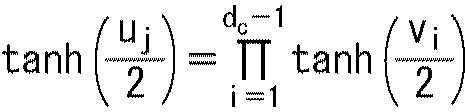

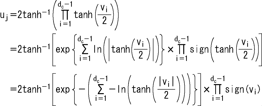
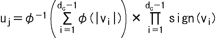
・・・(8) Hc T = 0
... (8)
・・・(9) K = (k + 1) x 360
... (9)
・・・(10) H wj = mod {h i, j + mod ((w-1), P) × q, M)
(10)
39,47,96,176,33,75,165,38,27,58,90,76,17,46,10,91,133,69,171,32,117,78,13,146,101,36,0,138,25,77,122,49,14,125,140,93,130,2,104,102,128,4,111,151,84,167,35,127,156,55,82,85,66,114,8,147,115,113,5,31,100,106,48,52,67,107,18,126,112,50,9,143,28,160,71,79,43,98,86,94,64,3,166,105,103,118,63,51,139,172,141,175,56,74,95,29,45,129,120,168,92,150,7,162,153,137,108,159,157,173,23,89,132,57,37,70,134,40,21,149,80,1,121,59,110,142,152,15,154,145,12,170,54,155,99,22,123,72,177,131,116,44,158,73,11,65,164,119,174,34,83,53,24,42,60,26,161,68,178,41,148,109,87,144,135,20,62,81,169,124,6,19,30,163,61,179,136,97,16,88
の並びにインターリーブされる。 According to the GW pattern of FIG. 109, the bit groups 0 to 179 of the 64 kbit LDPC code are arranged in bit groups 39, 47, 96, 176, 33, 75, 165, 38, 27, 58, 90, 76, 17, 46, 10, 91, 133, 69, 171, 32, 117, 78, 13, 146, 101, 36, 0, 138, 25, 77, 122, 49, 14, 125, 140, 93, 130, 2,104,102,128,4,111,151,84,167,35,127,156,55,82,85,66,114,8,147,115,113,5,31,100,106, 48, 52, 67, 107, 18, 126, 112, 50, 9, 143, 28, 160, 71, 79, 43, 98, 86, 94, 64, 3, 166, 105, 103, 118, 63, 51,139,172,141,175,56,74,95,29,45,129,120,168,92,150,7,162,153,137,108,159,157,173,23,89, 132, 57, 37, 70, 134, 40, 21, 149, 80, 1, 121, 59, 110, 142, 152, 15, 154, 145, 12, 170, 54, 155, 99, 22, 123, 72, 177, 131, 116, 44, 158, 73, 11, 65, 164, 119, 174, 34, 83, 53, 24, 42, 60, 26, 161, 68, 178, 41, 148, 109, 87, 144, 135, 20, 62, 81, 169, 124, 6, 19, 30, 163, 61, 179, 136, 97, 16, 88
Are interleaved.
6,14,1,127,161,177,75,123,62,103,17,18,167,88,27,34,8,110,7,78,94,44,45,166,149,61,163,145,155,157,82,130,70,92,151,139,160,133,26,2,79,15,95,122,126,178,101,24,138,146,179,30,86,58,11,121,159,49,84,132,117,119,50,52,4,51,48,74,114,59,40,131,33,89,66,136,72,16,134,37,164,77,99,173,20,158,156,90,41,176,81,42,60,109,22,150,105,120,12,64,56,68,111,21,148,53,169,97,108,35,140,91,115,152,36,106,154,0,25,54,63,172,80,168,142,118,162,135,73,83,153,141,9,28,55,31,112,107,85,100,175,23,57,47,38,170,137,76,147,93,19,98,124,39,87,174,144,46,10,129,69,71,125,96,116,171,128,65,102,5,43,143,104,13,67,29,3,113,32,165
の並びにインターリーブされる。 According to the GW pattern of FIG. 110, the arrangement of the bit groups 0 to 179 of the 64 kbit LDPC code is the bit groups 6, 14, 1, 127, 161, 177, 75, 123, 62, 103, 17, 18, 167, 88, 27, 34, 8, 110, 7, 78, 94, 44, 45, 166, 149, 61, 163, 145, 155, 157, 82, 130, 70, 92, 151, 139, 160, 133, 26, 2, 79, 15, 95, 122, 126, 178, 101, 24, 138, 146, 179, 30, 86, 58, 11, 121, 159, 49, 84, 132, 117, 119, 50, 52, 4, 51, 48, 74, 114, 59, 40, 131, 33, 89, 66, 136, 72, 16, 134, 37, 164, 77, 99, 173, 20, 158, 156, 90, 41, 176, 81, 42, 60, 109, 22, 150, 105, 120, 12, 64, 56, 68, 111, 21, 148, 53, 169, 97, 108, 35, 140, 91, 115,152,36,106,154,0,25,54,63,172,80,168,142,118,162,135,73,83,153,141,9,28,55,31,112, 107, 85, 100, 175, 23, 57, 47, 38, 170, 137, 76, 147, 93, 19, 98, 124, 39, 87, 174, 144, 46, 10, 129, 69, 71, 125, 96, 116, 171, 128, 65, 102, 5, 43, 143, 104, 13, 67, 29, 3, 113, 32, 165
Are interleaved.
103,116,158,0,27,73,140,30,148,36,153,154,10,174,122,178,6,106,162,59,142,112,7,74,11,51,49,72,31,65,156,95,171,105,173,168,1,155,125,82,86,161,57,165,54,26,121,25,157,93,22,34,33,39,19,46,150,141,12,9,79,118,24,17,85,117,67,58,129,160,89,61,146,77,130,102,101,137,94,69,14,133,60,149,136,16,108,41,90,28,144,13,175,114,2,18,63,68,21,109,53,123,75,81,143,169,42,119,138,104,4,131,145,8,5,76,15,88,177,124,45,97,64,100,37,132,38,44,107,35,43,80,50,91,152,78,166,55,115,170,159,147,167,87,83,29,96,172,48,98,62,139,70,164,84,47,151,134,126,113,179,110,111,128,32,52,66,40,135,176,99,127,163,3,120,71,56,92,23,20
の並びにインターリーブされる。 According to the GW pattern of FIG. 111, the arrangement of the bit groups 0 to 179 of the 64-kbit LDPC code is the bit groups 103, 116, 158, 0, 27, 73, 140, 30, 148, 36, 153, 154, 10, 174, 122, 178, 6, 106, 162, 59, 142, 112, 7, 74, 11, 51, 49, 72, 31, 65, 156, 95, 171, 105, 173, 168, 1, 155, 125, 82, 86, 161, 57, 165, 54, 26, 121, 25, 157, 93, 22, 34, 33, 39, 19, 46, 150, 141, 12, 9, 79, 118, 24, 17, 85, 117, 67, 58, 129, 160, 89, 61, 146, 77, 130, 102, 101, 137, 94, 69, 14, 133, 60, 149, 136, 16, 108, 41, 90, 28, 144, 13, 175, 114, 2, 18, 63, 68, 21, 109, 53, 123, 75, 81, 143, 169, 42, 119, 138, 104, 4, 131, 145, 8, 5, 76, 15, 88, 177, 124, 45, 97, 64, 100, 37, 132, 38, 44, 107, 35, 43, 80, 50, 91, 152, 78, 166, 55,115,170,159,147,167,87,83,29,96,172,48,98,62,139,70,164,84,47,151,134,126,1 13,179,110,111,128,32,52,66,40,135,176,99,127,163,3,120,71,56,92,23,20
Are interleaved.
139,106,125,81,88,104,3,66,60,65,2,95,155,24,151,5,51,53,29,75,52,85,8,22,98,93,168,15,86,126,173,100,130,176,20,10,87,92,175,36,143,110,67,146,149,127,133,42,84,64,78,1,48,159,79,138,46,112,164,31,152,57,144,69,27,136,122,170,132,171,129,115,107,134,89,157,113,119,135,45,148,83,114,71,128,161,140,26,13,59,38,35,96,28,0,80,174,137,49,16,101,74,179,91,44,55,169,131,163,123,145,162,108,178,12,77,167,21,154,82,54,90,177,17,41,39,7,102,156,62,109,14,37,23,153,6,147,50,47,63,18,70,68,124,72,33,158,32,118,99,105,94,25,121,166,120,160,141,165,111,19,150,97,76,73,142,117,4,172,58,11,30,9,103,40,61,43,34,56,116
の並びにインターリーブされる。 According to the GW pattern of FIG. 112, the bit groups 0 to 179 of the 64 kbit LDPC code are arranged in bit groups 139, 106, 125, 81, 88, 104, 3, 66, 60, 65, 2, 95, 155, 24, 151, 5, 51, 53, 29, 75, 52, 85, 8, 22, 98, 93, 168, 15, 86, 126, 173, 100, 130, 176, 20, 10, 87, 92,175,36,143,110,67,146,149,127,133,42,84,64,78,1,48,159,79,138,46,112,164,31,152,57, 144, 69, 27, 136, 122, 170, 132, 171, 129, 115, 107, 134, 89, 157, 113, 119, 135, 45, 148, 83, 114, 71, 128, 161, 140, 26, 13, 59, 38, 35, 96, 28, 0, 80, 174, 137, 49, 16, 101, 74, 179, 91, 44, 55, 169, 131, 163, 123, 145, 162, 108,178,12,77,167,21,154,82,54,90,177,17,41,39,7,102,156,62,109,14,37,23,153,6,147, 50, 47, 63, 18, 70, 68, 124, 72, 33, 158, 32, 118, 99, 105, 94, 25, 121, 166, 120, 160, 141, 165 111, 19, 150, 97, 76, 73, 142, 117, 4, 172, 58, 11, 30, 9, 103, 40, 61, 43, 34, 56, 116
Are interleaved.
72,59,65,61,80,2,66,23,69,101,19,16,53,109,74,106,113,56,97,30,164,15,25,20,117,76,50,82,178,13,169,36,107,40,122,138,42,96,27,163,46,64,124,57,87,120,168,166,39,177,22,67,134,9,102,28,148,91,83,88,167,32,99,140,60,152,1,123,29,154,26,70,149,171,12,6,55,100,62,86,114,174,132,139,7,45,103,130,31,49,151,119,79,41,118,126,3,179,110,111,51,93,145,73,133,54,104,161,37,129,63,38,95,159,89,112,115,136,33,68,17,35,137,173,143,78,77,141,150,58,158,125,156,24,105,98,43,84,92,128,165,153,108,0,121,170,131,144,47,157,11,155,176,48,135,4,116,146,127,52,162,142,8,5,34,85,90,44,172,94,160,175,75,71,18,147,10,21,14,81
の並びにインターリーブされる。 According to the GW pattern of FIG. 113, the arrangement of the bit groups 0 to 179 of the 64 kbit LDPC code is the bit groups 72, 59, 65, 61, 80, 2, 66, 23, 69, 101, 19, 16, 53, 109, 74, 106, 113, 56, 97, 30, 164, 15, 25, 20, 117, 76, 50, 82, 178, 13, 169, 36, 107, 40, 122, 138, 42, 96, 27, 163, 46, 64, 124, 57, 87, 120, 168, 166, 39, 177, 22, 67, 134, 9, 102, 28, 148, 91, 83, 88, 167, 32, 99, 140, 60, 152, 1, 123, 29, 154, 26, 70, 149, 171, 12, 6, 55, 100, 62, 86, 114, 174, 132, 139, 7, 45, 103, 130, 31, 49, 151, 119, 79, 41, 118, 126, 3, 179, 110, 111, 51, 93, 145, 73, 133, 54, 104, 161, 37, 129, 63, 38, 95,159,89,112,115,136,33,68,17,35,137,173,143,78,77,141,150,58,158,125,156,24,105,98,43, 84, 92, 128, 165, 153, 108, 0, 121, 170, 131, 144, 47, 157, 11, 155, 176, 48, 135, 4, 116, 146, 12 7, 52, 162, 142, 8, 5, 34, 85, 90, 44, 172, 94, 160, 175, 75, 71, 18, 147, 10, 21, 14, 81
Are interleaved.
8,27,7,70,75,84,50,131,146,99,96,141,155,157,82,57,120,38,137,13,83,23,40,9,56,171,124,172,39,142,20,128,133,2,89,153,103,112,129,151,162,106,14,62,107,110,73,71,177,154,80,176,24,91,32,173,25,16,17,159,21,92,6,67,81,37,15,136,100,64,102,163,168,18,78,76,45,140,123,118,58,122,11,19,86,98,119,111,26,138,125,74,97,63,10,152,161,175,87,52,60,22,79,104,30,158,54,145,49,34,166,109,179,174,93,41,116,48,3,29,134,167,105,132,114,169,147,144,77,61,170,90,178,0,43,149,130,117,47,44,36,115,88,101,148,69,46,94,143,164,139,126,160,156,33,113,65,121,53,42,66,165,85,127,135,5,55,150,72,35,31,51,4,1,68,12,28,95,59,108
の並びにインターリーブされる。 According to the GW pattern of FIG. 114, the arrangement of the bit groups 0 to 179 of the 64-kbit LDPC code is the bit groups 8, 27, 7, 70, 75, 84, 50, 131, 146, 99, 96, 141, 155,157,82,57,120,38,137,13,83,23,40,9,56,171,124,172,39,142,20,128,133,2,89,153,103, 112,129,151,162,106,14,62,107,110,73,71,177,154,80,176,24,91,32,173,25,16,17,159,21,92, 6, 67, 81, 37, 15, 136, 100, 64, 102, 163, 168, 18, 78, 76, 45, 140, 123, 118, 58, 122, 11, 19, 86, 98, 119, 111, 26, 138, 125, 74, 97, 63, 10, 152, 161, 175, 87, 52, 60, 22, 79, 104, 30, 158, 54, 145, 49, 34, 166, 109, 179, 174, 93, 41, 116, 48, 3, 29, 134, 167, 105, 132, 114, 169, 147, 144, 77, 61, 170, 90, 178, 0, 43, 149, 130, 117, 47, 44, 36, 115, 88, 101, 148, 69, 46, 94, 143, 164, 139, 126, 160, 156, 33, 113, 65, 121 53,42,66,165,85,127,135,5,55,150,72,35,31,51,4,1,68,12,28,95,59,108
Are interleaved.
0,2,4,6,8,10,12,14,16,18,20,22,24,26,28,30,32,34,36,38,40,42,44,46,48,50,52,54,56,58,60,62,64,66,68,70,72,74,76,78,80,82,84,86,88,90,92,94,96,98,100,102,104,106,108,110,112,114,116,118,120,122,124,126,128,130,132,134,136,138,140,142,144,146,148,150,152,154,156,158,160,162,164,166,168,170,172,174,176,178,1,3,5,7,9,11,13,15,17,19,21,23,25,27,29,31,33,35,37,39,41,43,45,47,49,51,53,55,57,59,61,63,65,67,69,71,73,75,77,79,81,83,85,87,89,91,93,95,97,99,101,103,105,107,109,111,113,115,117,119,121,123,125,127,129,131,133,135,137,139,141,143,145,147,149,151,153,155,157,159,161,163,165,167,169,171,173,175,177,179
の並びにインターリーブされる。 According to the GW pattern of FIG. 115, the arrangement of bit groups 0 to 179 of the 64-kbit LDPC code is represented by bit groups 0, 2, 4, 6, 8, 10, 12, 14, 16, 18, 20, 22, 24, 26, 28, 30, 32, 34, 36, 38, 40, 42, 44, 46, 48, 50, 52, 54, 56, 58, 60, 62, 64, 66, 68, 70, 72, 74, 76, 78, 80, 82, 84, 86, 88, 90, 92, 94, 96, 98, 100, 102, 104, 106, 108, 110, 112, 114, 116, 118, 120, 122, 124, 126, 128, 130, 132, 134, 136, 138, 140, 142, 144, 146, 148, 150, 152, 154, 156, 158, 160, 162, 164, 166, 168, 170, 172, 174, 176, 178, 1, 3, 5, 7, 9, 11, 13, 15, 17, 19, 21, 23, 25, 27, 29, 31, 33, 35, 37, 39, 41, 43, 45, 47, 49, 51, 53, 55, 57, 59, 61, 63, 65, 67, 69, 71, 73, 75, 77, 79, 81, 83, 85, 87, 89, 91, 93, 95, 97, 99, 101, 103, 105, 107, 109, 111, 113, 115, 117, 119, 121, 123, 125, 127, 129, 131, 133, 135, 137, 139, 141, 1 43,145,147,149,151,153,155,157,159,161,163,165,167,169,171,173,175,177,179
Are interleaved.
11,5,8,18,1,25,32,31,19,21,50,102,65,85,45,86,98,104,64,78,72,53,103,79,93,41,82,108,112,116,120,124,128,132,136,140,144,148,152,156,160,164,168,172,176,4,12,15,3,10,20,26,34,23,33,68,63,69,92,44,90,75,56,100,47,106,42,39,97,99,89,52,109,113,117,121,125,129,133,137,141,145,149,153,157,161,165,169,173,177,6,16,14,7,13,36,28,29,37,73,70,54,76,91,66,80,88,51,96,81,95,38,57,105,107,59,61,110,114,118,122,126,130,134,138,142,146,150,154,158,162,166,170,174,178,0,9,17,2,27,30,24,22,35,77,74,46,94,62,87,83,101,49,43,84,48,60,67,71,58,40,55,111,115,119,123,127,131,135,139,143,147,151,155,159,163,167,171,175,179
の並びにインターリーブされる。 According to the GW pattern of FIG. 116, the arrangement of the bit groups 0 to 179 of the 64 kbit LDPC code is represented by bit groups 11, 5, 8, 18, 1, 25, 32, 31, 19, 21, 50, 102, 65, 85, 45, 86, 98, 104, 64, 78, 72, 53, 103, 79, 93, 41, 82, 108, 112, 116, 120, 124, 128, 132, 136, 140, 144, 148, 152, 156, 160, 164, 168, 172, 176, 4, 12, 15, 3, 10, 20, 26, 34, 23, 33, 68, 63, 69, 92, 44, 90, 75, 56, 100, 47, 106, 42, 39, 97, 99, 89, 52, 109, 113, 117, 121, 125, 129, 133, 137, 141, 145, 149, 153, 157, 161, 165, 169, 173, 177, 6, 16, 14, 7, 13, 36, 28, 29, 37, 73, 70, 54, 76, 91, 66, 80, 88, 51, 96, 81, 95, 38, 57,105,107,59,61,110,114,118,122,126,130,134,138,142,146,150,154,158,162,166,170,174,178,0,9, 17, 2, 27, 30, 24, 22, 35, 77, 74, 46, 94, 62, 87, 83, 101, 49, 43, 84, 48, 60, 67, 71, 58, 40, 55, 111, 115, 119, 123, 127, 131, 135, 139, 143, 147, 151, 155, 159, 163, 167, 171, 175, 179
Are interleaved.
9,18,15,13,35,26,28,99,40,68,85,58,63,104,50,52,94,69,108,114,120,126,132,138,144,150,156,162,168,174,8,16,17,24,37,23,22,103,64,43,47,56,92,59,70,42,106,60,109,115,121,127,133,139,145,151,157,163,169,175,4,1,10,19,30,31,89,86,77,81,51,79,83,48,45,62,67,65,110,116,122,128,134,140,146,152,158,164,170,176,6,2,0,25,20,34,98,105,82,96,90,107,53,74,73,93,55,102,111,117,123,129,135,141,147,153,159,165,171,177,14,7,3,27,21,33,44,97,38,75,72,41,84,80,100,87,76,57,112,118,124,130,136,142,148,154,160,166,172,178,5,11,12,32,29,36,88,71,78,95,49,54,61,66,46,39,101,91,113,119,125,131,137,143,149,155,161,167,173,179
の並びにインターリーブされる。 According to the GW pattern of FIG. 117, the arrangement of the bit groups 0 to 179 of the 64-kbit LDPC code is represented by bit groups 9, 18, 15, 13, 35, 26, 28, 99, 40, 68, 85, 58, 63, 104, 50, 52, 94, 69, 108, 114, 120, 126, 132, 138, 144, 150, 156, 162, 168, 174, 8, 16, 17, 24, 37, 23, 22, 103, 64, 43, 47, 56, 92, 59, 70, 42, 106, 60, 109, 115, 121, 127, 133, 139, 145, 151, 157, 163, 169, 175, 4, 1, 10, 19, 30, 31, 89, 86, 77, 81, 51, 79, 83, 48, 45, 62, 67, 65, 110, 116, 122, 128, 134, 140, 146, 152, 158, 164, 170, 176, 6, 2, 0, 25, 20, 34, 98, 105, 82, 96, 90, 107, 53, 74, 73, 93, 55, 102, 111, 117, 123, 129, 135, 141, 147, 153, 159, 165, 171, 177, 14, 7, 3, 27, 21, 33, 44, 97, 38, 75, 72, 41, 84, 80, 100, 87, 76, 57,112,118,124,130,136,142,148,154,160,166,172,178,5,11,12,32,29,36,88,71,78,95, 49, 54, 61, 66, 46, 39, 101, 91, 113, 119, 125, 131, 137, 143, 149, 155, 161, 167, 173, 179
Are interleaved.
0,14,19,21,2,11,22,9,8,7,16,3,26,24,27,80,100,121,107,31,36,42,46,49,75,93,127,95,119,73,61,63,117,89,99,129,52,111,124,48,122,82,106,91,92,71,103,102,81,113,101,97,33,115,59,112,90,51,126,85,123,40,83,53,69,70,132,134,136,138,140,142,144,146,148,150,152,154,156,158,160,162,164,166,168,170,172,174,176,178,4,5,10,12,20,6,18,13,17,15,1,29,28,23,25,67,116,66,104,44,50,47,84,76,65,130,56,128,77,39,94,87,120,62,88,74,35,110,131,98,60,37,45,78,125,41,34,118,38,72,108,58,43,109,57,105,68,86,79,96,32,114,64,55,30,54,133,135,137,139,141,143,145,147,149,151,153,155,157,159,161,163,165,167,169,171,173,175,177,179
の並びにインターリーブされる。 According to the GW pattern of FIG. 118, the arrangement of bit groups 0 to 179 of the 64-kbit LDPC code is represented by bit groups 0, 14, 19, 21, 2, 11, 22, 9, 8, 7, 16, 3, 26, 24, 27, 80, 100, 121, 107, 31, 36, 42, 46, 49, 75, 93, 127, 95, 119, 73, 61, 63, 117, 89, 99, 129, 52, 111, 124, 48, 122, 82, 106, 91, 92, 71, 103, 102, 81, 113, 101, 97, 33, 115, 59, 112, 90, 51, 126, 85, 123, 40, 83,53,69,70,132,134,136,138,140,142,144,146,148,150,152,154,156,158,160,162,164,166,168,170,172, 174, 176, 178, 4, 5, 10, 12, 20, 6, 18, 13, 17, 15, 1, 29, 28, 23, 25, 67, 116, 66, 104, 44, 50, 47, 84, 76, 65, 130, 56, 128, 77, 39, 94, 87, 120, 62, 88, 74, 35, 110, 131, 98, 60, 37, 45, 78, 125, 41, 34, 118, 38, 72, 108, 58, 43, 109, 57, 105, 68, 86, 79, 96, 32, 114, 64, 55, 30, 54, 133, 135, 137, 139, 141, 1 43,145,147,149,151,153,155,157,159,161,163,165,167,169,171,173,175,177,179
Are interleaved.
21,11,12,9,0,6,24,25,85,103,118,122,71,101,41,93,55,73,100,40,106,119,45,80,128,68,129,61,124,36,126,117,114,132,136,140,144,148,152,156,160,164,168,172,176,20,18,10,13,16,8,26,27,54,111,52,44,87,113,115,58,116,49,77,95,86,30,78,81,56,125,53,89,94,50,123,65,83,133,137,141,145,149,153,157,161,165,169,173,177,2,17,1,4,7,15,29,82,32,102,76,121,92,130,127,62,107,38,46,43,110,75,104,70,91,69,96,120,42,34,79,35,105,134,138,142,146,150,154,158,162,166,170,174,178,19,5,3,14,22,28,23,109,51,108,131,33,84,88,64,63,59,57,97,98,48,31,99,37,72,39,74,66,60,67,47,112,90,135,139,143,147,151,155,159,163,167,171,175,179
の並びにインターリーブされる。 According to the GW pattern of FIG. 119, the arrangement of the bit groups 0 to 179 of the 64 kbit LDPC code is represented by bit groups 21, 11, 12, 9, 0, 6, 24, 25, 85, 103, 118, 122, 71, 101, 41, 93, 55, 73, 100, 40, 106, 119, 45, 80, 128, 68, 129, 61, 124, 36, 126, 117, 114, 132, 136, 140, 144, 148, 152, 156, 160, 164, 168, 172, 176, 20, 18, 10, 13, 16, 8, 26, 27, 54, 111, 52, 44, 87, 113, 115, 58, 116, 49,77,95,86,30,78,81,56,125,53,89,94,50,123,65,83,133,137,141,145,149,153,157,161,165, 169, 173, 177, 2, 17, 1, 4, 7, 15, 29, 82, 32, 102, 76, 121, 92, 130, 127, 62, 107, 38, 46, 43, 110, 75, 104, 70, 91, 69, 96, 120, 42, 34, 79, 35, 105, 134, 138, 142, 146, 150, 154, 158, 162, 166, 170, 174, 178, 19, 5, 3, 14, 22, 28, 23, 109, 51, 108, 131, 33, 84, 88, 64, 63, 59, 57, 97, 98, 48, 31, 99, 37, 72, 39, 74, 66, 60, 67, 47, 112, 90, 135, 139, 143, 147, 151, 155, 159, 163, 167, 171, 175, 179
Are interleaved.
12,15,2,16,27,50,35,74,38,70,108,32,112,54,30,122,72,116,36,90,49,85,132,138,144,150,156,162,168,174,0,14,9,5,23,66,68,52,96,117,84,128,100,63,60,127,81,99,53,55,103,95,133,139,145,151,157,163,169,175,10,22,13,11,28,104,37,57,115,46,65,129,107,75,119,110,31,43,97,78,125,58,134,140,146,152,158,164,170,176,4,19,6,8,24,44,101,94,118,130,69,71,83,34,86,124,48,106,89,40,102,91,135,141,147,153,159,165,171,177,3,20,7,17,25,87,41,120,47,80,59,62,88,45,56,131,61,126,113,92,51,98,136,142,148,154,160,166,172,178,21,18,1,26,29,39,73,121,105,77,42,114,93,82,111,109,67,79,123,64,76,33,137,143,149,155,161,167,173,179
の並びにインターリーブされる。 According to the GW pattern of FIG. 120, the arrangement of the bit groups 0 to 179 of the 64 kbit LDPC code is the bit groups 12, 15, 2, 16, 27, 50, 35, 74, 38, 70, 108, 32, 112, 54, 30, 122, 72, 116, 36, 90, 49, 85, 132, 138, 144, 150, 156, 162, 168, 174, 0, 14, 9, 5, 23, 66, 68, 52, 96, 117, 84, 128, 100, 63, 60, 127, 81, 99, 53, 55, 103, 95, 133, 139, 145, 151, 157, 163, 169, 175, 10, 22, 13, 11, 28, 104, 37, 57, 115, 46, 65, 129, 107, 75, 119, 110, 31, 43, 97, 78, 125, 58, 134, 140, 146, 152, 158, 164, 170, 176, 4, 19, 6, 8, 24, 44, 101, 94, 118, 130, 69, 71, 83, 34, 86, 124, 48, 106, 89, 40, 102, 91, 135, 141, 147, 153, 159, 165, 171, 177, 3, 20, 7, 17, 25, 87, 41, 120, 47, 80, 59, 62, 88, 45, 56, 131, 61, 126, 113, 92, 51, 98, 136, 142, 148, 154, 160, 166, 172, 178, 21, 18, 1, 26, 29, 39, 73, 121, 105, 77 42,114,93,82,111,109,67,79,123,64,76,33,137,143,149,155,161,167,173,179
Are interleaved.
0,2,4,6,8,10,12,14,16,18,20,22,24,26,28,30,32,34,36,38,40,42,44,46,48,50,52,54,56,58,60,62,64,66,68,70,72,74,76,78,80,82,84,86,88,90,92,94,96,98,100,102,104,106,108,110,112,114,116,118,120,122,124,126,128,130,132,134,136,138,140,142,144,146,148,150,152,154,156,158,160,162,164,166,168,170,172,174,176,178,1,3,5,7,9,11,13,15,17,19,21,23,25,27,29,31,33,35,37,39,41,43,45,47,49,51,53,55,57,59,61,63,65,67,69,71,73,75,77,79,81,83,85,87,89,91,93,95,97,99,101,103,105,107,109,111,113,115,117,119,121,123,125,127,129,131,133,135,137,139,141,143,145,147,149,151,153,155,157,159,161,163,165,167,169,171,173,175,177,179
の並びにインターリーブされる。 According to the GW pattern of FIG. 121, the arrangement of bit groups 0 to 179 of 64 kbit LDPC codes is represented by bit groups 0, 2, 4, 6, 8, 10, 12, 14, 16, 18, 20, 22, 24, 26, 28, 30, 32, 34, 36, 38, 40, 42, 44, 46, 48, 50, 52, 54, 56, 58, 60, 62, 64, 66, 68, 70, 72, 74, 76, 78, 80, 82, 84, 86, 88, 90, 92, 94, 96, 98, 100, 102, 104, 106, 108, 110, 112, 114, 116, 118, 120, 122, 124, 126, 128, 130, 132, 134, 136, 138, 140, 142, 144, 146, 148, 150, 152, 154, 156, 158, 160, 162, 164, 166, 168, 170, 172, 174, 176, 178, 1, 3, 5, 7, 9, 11, 13, 15, 17, 19, 21, 23, 25, 27, 29, 31, 33, 35, 37, 39, 41, 43, 45, 47, 49, 51, 53, 55, 57, 59, 61, 63, 65, 67, 69, 71, 73, 75, 77, 79, 81, 83, 85, 87, 89, 91, 93, 95, 97, 99, 101, 103, 105, 107, 109, 111, 113, 115, 117, 119, 121, 123, 125, 127, 129, 131, 133, 135, 137, 139, 141, 1 43,145,147,149,151,153,155,157,159,161,163,165,167,169,171,173,175,177,179
Are interleaved.
0,4,8,12,16,20,24,28,32,36,40,44,48,52,56,60,64,68,72,76,80,84,88,92,96,100,104,108,112,116,120,124,128,132,136,140,144,148,152,156,160,164,168,172,176,1,5,9,13,17,21,25,29,33,37,41,45,49,53,57,61,65,69,73,77,81,85,89,93,97,101,105,109,113,117,121,125,129,133,137,141,145,149,153,157,161,165,169,173,177,2,6,10,14,18,22,26,30,34,38,42,46,50,54,58,62,66,70,74,78,82,86,90,94,98,102,106,110,114,118,122,126,130,134,138,142,146,150,154,158,162,166,170,174,178,3,7,11,15,19,23,27,31,35,39,43,47,51,55,59,63,67,71,75,79,83,87,91,95,99,103,107,111,115,119,123,127,131,135,139,143,147,151,155,159,163,167,171,175,179
の並びにインターリーブされる。 According to the GW pattern of FIG. 122, the arrangement of the bit groups 0 to 179 of the 64-kbit LDPC code is represented by bit groups 0, 4, 8, 12, 16, 20, 24, 28, 32, 36, 40, 44, 48, 52, 56, 60, 64, 68, 72, 76, 80, 84, 88, 92, 96, 100, 104, 108, 112, 116, 120, 124, 128, 132, 136, 140, 144, 148, 152, 156, 160, 164, 168, 172, 176, 1, 5, 9, 13, 17, 21, 25, 29, 33, 37, 41, 45, 49, 53, 57, 61, 65, 69,73,77,81,85,89,93,97,101,105,109,113,117,121,125,129,133,137,141,145,149,153,157,161,165, 169, 173, 177, 2, 6, 10, 14, 18, 22, 26, 30, 34, 38, 42, 46, 50, 54, 58, 62, 66, 70, 74, 78, 82, 86, 90, 94, 98, 102, 106, 110, 114, 118, 122, 126, 130, 134, 138, 142, 146, 150, 154, 158, 162, 166, 170, 174, 178, 3, 7, 11, 15, 19, 23, 27, 31, 35, 39, 43, 47, 51, 55, 59, 63, 67, 71, 75, 79, 83, 87, 91, 95, 99, 103, 1 07, 111, 115, 119, 123, 127, 131, 135, 139, 143, 147, 151, 155, 159, 163, 167, 171, 175, 179
Are interleaved.
8,112,92,165,12,55,5,126,87,70,69,94,103,78,137,148,9,60,13,7,178,79,43,136,34,68,118,152,49,15,99,61,66,28,109,125,33,167,81,93,97,26,35,30,153,131,122,71,107,130,76,4,95,42,58,134,0,89,75,40,129,31,80,101,52,16,142,44,138,46,116,27,82,88,143,128,72,29,83,117,172,14,51,159,48,160,100,1,102,90,22,3,114,19,108,113,39,73,111,155,106,105,91,150,54,25,135,139,147,36,56,123,6,67,104,96,157,10,62,164,86,74,133,120,174,53,140,156,171,149,127,85,59,124,84,11,21,132,41,145,158,32,17,23,50,169,170,38,18,151,24,166,175,2,47,57,98,20,177,161,154,176,163,37,110,168,141,64,65,173,162,121,45,77,115,179,63,119,146,144
の並びにインターリーブされる。 According to the GW pattern of FIG. 123, the arrangement of the bit groups 0 to 179 of the 64 kbit LDPC code is represented by bit groups 8, 112, 92, 165, 12, 55, 5, 126, 87, 70, 69, 94, 103, 78, 137, 148, 9, 60, 13, 7, 178, 79, 43, 136, 34, 68, 118, 152, 49, 15, 99, 61, 66, 28, 109, 125, 33, 167, 81, 93, 97, 26, 35, 30, 153, 131, 122, 71, 107, 130, 76, 4, 95, 42, 58, 134, 0, 89, 75, 40, 129, 31, 80, 101, 52, 16, 142, 44, 138, 46, 116, 27, 82, 88, 143, 128, 72, 29, 83, 117, 172, 14, 51, 159, 48, 160, 100, 1,102,90,22,3,114,19,108,113,39,73,111,155,106,105,91,150,54,25,135,139,147,36,56,123, 6, 67, 104, 96, 157, 10, 62, 164, 86, 74, 133, 120, 174, 53, 140, 156, 171, 149, 127, 85, 59, 124, 84, 11, 21, 132, 41, 145, 158, 32, 17, 23, 50, 169, 170, 38, 18, 151, 24, 166, 175, 2, 47, 57, 98, 20, 177, 161, 1 54,176,163,37,110,168,141,64,65,173,162,121,45,77,115,179,63,119,146,144
Are interleaved.
103,138,168,82,116,45,178,28,160,2,129,148,150,23,54,106,24,78,49,87,145,179,26,112,119,12,18,174,21,48,134,137,102,147,152,72,68,3,22,169,30,64,108,142,131,13,113,115,121,37,133,136,101,59,73,161,38,164,43,167,42,144,41,85,91,58,128,154,172,57,75,17,157,19,4,86,15,25,35,9,105,123,14,34,56,111,60,90,74,149,146,62,163,31,16,141,88,6,155,130,89,107,135,79,8,10,124,171,114,162,33,66,126,71,44,158,51,84,165,173,120,7,11,170,176,1,156,96,175,153,36,47,110,63,132,29,95,143,98,70,20,122,53,100,93,140,109,139,76,151,52,61,46,125,94,50,67,81,69,65,40,127,77,32,39,27,99,97,159,166,80,117,55,92,118,0,5,83,177,104
の並びにインターリーブされる。 According to the GW pattern of FIG. 124, the arrangement of the bit groups 0 to 179 of the 64-kbit LDPC code is the bit groups 103, 138, 168, 82, 116, 45, 178, 28, 160, 2, 129, 148, 150, 23, 54, 106, 24, 78, 49, 87, 145, 179, 26, 112, 119, 12, 18, 174, 21, 48, 134, 137, 102, 147, 152, 72, 68, 3, 22, 169, 30, 64, 108, 142, 131, 13, 113, 115, 121, 37, 133, 136, 101, 59, 73, 161, 38, 164, 43, 167, 42, 144, 41, 85, 91, 58, 128, 154, 172, 57, 75, 17, 157, 19, 4, 86, 15, 25, 35, 9, 105, 123, 14, 34, 56, 111, 60, 90, 74, 149, 146, 62, 163, 31, 16, 141, 88, 6, 155, 130, 89, 107, 135, 79, 8, 10, 124, 171, 114, 162, 33, 66, 126, 71, 44, 158, 51, 84, 165, 173, 120, 7, 11, 170, 176, 1, 156, 96, 175, 153, 36, 47, 110, 63, 132, 29, 95, 143, 98, 70, 20, 122, 53, 100, 93, 140, 109, 139, 76, 151, 52, 61, 46, 125, 94, 50, 67, 81, 69 , 65, 40, 127, 77, 32, 39, 27, 99, 97, 159, 166, 80, 117, 55, 92, 118, 0, 5, 83, 177, 104
Are interleaved.
104,120,47,136,116,109,22,20,117,61,52,108,86,99,76,90,37,58,36,138,95,130,177,93,56,33,24,82,0,67,83,46,79,70,154,18,75,43,49,63,162,16,167,80,125,1,123,107,9,45,53,15,38,23,57,141,4,178,165,113,21,105,11,124,126,77,146,29,131,27,176,40,74,91,140,64,73,44,129,157,172,51,10,128,119,163,103,28,85,156,78,6,8,173,160,106,31,54,122,25,139,68,150,164,87,135,97,166,42,169,161,137,26,39,133,5,94,69,2,30,171,149,115,96,145,101,92,143,12,88,81,71,19,147,50,152,159,155,151,174,60,32,3,142,72,14,170,112,65,89,175,158,17,114,62,144,13,98,66,59,7,118,48,153,100,134,84,111,132,127,41,168,110,102,34,121,179,148,55,35
の並びにインターリーブされる。 According to the GW pattern of FIG. 125, the arrangement of the bit groups 0 to 179 of the 64-kbit LDPC code is the bit groups 104, 120, 47, 136, 116, 109, 22, 20, 117, 61, 52, 108, 86, 99, 76, 90, 37, 58, 36, 138, 95, 130, 177, 93, 56, 33, 24, 82, 0, 67, 83, 46, 79, 70, 154, 18, 75, 43, 49, 63, 162, 16, 167, 80, 125, 1, 123, 107, 9, 45, 53, 15, 38, 23, 57, 141, 4, 178, 165, 113, 21, 105, 11, 124, 126, 77, 146, 29, 131, 27, 176, 40, 74, 91, 140, 64, 73, 44, 129, 157, 172, 51, 10, 128, 119, 163, 103, 28, 85, 156, 78, 6, 8, 173, 160, 106, 31, 54, 122, 25, 139, 68, 150, 164, 87, 135, 97, 166, 42, 169, 161, 137, 26, 39, 133, 5, 94, 69, 2, 30, 171, 149, 115, 96, 145, 101, 92, 143, 12, 88, 81, 71, 19, 147, 50, 152, 159, 155, 151, 174, 60, 32, 3, 142, 72, 14, 170, 112, 65, 89, 175, 158, 17, 114, 62, 144, 13, 98, 66, 59 7,118,48,153,100,134,84,111,132,127,41,168,110,102,34,121,179,148,55,35
Are interleaved.
37,98,160,63,18,6,94,136,8,50,0,75,65,32,107,60,108,17,21,156,157,5,73,66,38,177,162,130,171,76,57,126,103,62,120,134,154,101,143,29,13,149,16,33,55,56,159,128,23,146,153,141,169,49,46,152,89,155,111,127,48,14,93,41,7,78,135,69,123,179,36,87,27,58,88,170,125,110,15,97,178,90,121,173,30,102,10,80,104,166,64,4,147,1,52,45,148,68,158,31,140,100,85,115,151,70,39,82,122,79,12,91,133,132,22,163,47,19,119,144,35,25,42,83,92,26,72,138,54,124,24,74,118,117,168,71,109,112,106,176,175,44,145,11,9,161,96,77,174,137,34,84,2,164,129,43,150,61,53,20,165,113,142,116,95,3,28,40,81,99,139,114,59,67,172,131,105,167,51,86
の並びにインターリーブされる。 According to the GW pattern of FIG. 126, the arrangement of the bit groups 0 to 179 of the 64 kbit LDPC code is represented by bit groups 37, 98, 160, 63, 18, 6, 94, 136, 8, 50, 0, 75, 65, 32, 107, 60, 108, 17, 21, 156, 157, 5, 73, 66, 38, 177, 162, 130, 171, 76, 57, 126, 103, 62, 120, 134, 154, 101, 143, 29, 13, 149, 16, 33, 55, 56, 159, 128, 23, 146, 153, 141, 169, 49, 46, 152, 89, 155, 111, 127, 48, 14, 93, 41, 7, 78, 135, 69, 123, 179, 36, 87, 27, 58, 88, 170, 125, 110, 15, 97, 178, 90, 121, 173, 30, 102, 10, 80, 104, 166, 64, 4, 147, 1, 52, 45, 148, 68, 158, 31, 140, 100, 85, 115, 151, 70, 39, 82, 122, 79, 12, 91, 133, 132, 22, 163, 47, 19, 119, 144, 35, 25, 42, 83, 92, 26, 72, 138, 54, 124, 24, 74, 118, 117, 168, 71, 109, 112, 106, 176, 175, 44, 145, 11, 9, 161, 96, 77, 174, 137, 34, 84, 2, 164, 129, 43, 150, 61, 53, 2 0,165,113,142,116,95,3,28,40,81,99,139,114,59,67,172,131,105,167,51,86
Are interleaved.
58,70,23,32,26,63,55,48,35,41,53,20,38,51,61,65,44,29,7,2,113,68,96,104,106,89,27,0,119,21,4,49,46,100,13,36,57,98,102,9,42,39,33,62,22,95,101,15,91,25,93,132,69,87,47,59,67,124,17,11,31,43,40,37,85,50,97,140,45,92,56,30,34,60,107,24,52,94,64,5,71,90,66,103,88,86,84,19,169,159,147,126,28,130,14,162,144,166,108,153,115,135,120,122,112,139,151,156,16,172,164,123,99,54,136,81,105,128,116,150,155,76,18,142,170,175,83,146,78,109,73,131,127,82,167,77,110,79,137,152,3,173,148,72,158,117,1,6,12,8,161,74,143,133,168,171,134,163,138,121,141,160,111,10,149,80,75,165,157,174,129,145,114,125,154,118,176,177,178,179
の並びにインターリーブされる。 According to the GW pattern of FIG. 127, the arrangement of the bit groups 0 to 179 of the 64-kbit LDPC code is the bit groups 58, 70, 23, 32, 26, 63, 55, 48, 35, 41, 53, 20, 38, 51, 61, 65, 44, 29, 7, 2, 113, 68, 96, 104, 106, 89, 27, 0, 119, 21, 4, 49, 46, 100, 13, 36, 57, 98, 102, 9, 42, 39, 33, 62, 22, 95, 101, 15, 91, 25, 93, 132, 69, 87, 47, 59, 67, 124, 17, 11, 31, 43, 40, 37, 85, 50, 97, 140, 45, 92, 56, 30, 34, 60, 107, 24, 52, 94, 64, 5, 71, 90, 66, 103, 88, 86, 84, 19, 169, 159, 147, 126, 28, 130, 14, 162, 144, 166, 108, 153, 115, 135, 120, 122, 112, 139, 151, 156, 16, 172, 164, 123, 99, 54, 136, 81, 105, 128, 116, 150, 155, 76, 18, 142, 170, 175, 83, 146, 78, 109, 73, 131, 127, 82, 167, 77, 110, 79,137,152,3,173,148,72,158,117,1,6,12,8,161,74,143,133,168,171,134,163,138,121,141 160,111,10,149,80,75,165,157,174,129,145,114,125,154,118,176,177,178,179
Are interleaved.
40,159,100,14,88,75,53,24,157,84,23,77,140,145,32,28,112,39,76,50,93,27,107,25,152,101,127,5,129,71,9,21,96,73,35,106,158,49,136,30,137,115,139,48,167,85,74,72,7,110,161,41,170,147,82,128,149,33,8,120,47,68,58,67,87,155,11,18,103,151,29,36,83,135,79,150,97,54,70,138,156,31,121,34,20,130,61,57,2,166,117,15,6,165,118,98,116,131,109,62,126,175,22,111,164,16,133,102,55,105,64,177,78,37,162,124,119,19,4,69,132,65,123,160,17,52,38,1,80,90,42,81,104,13,144,51,114,3,43,146,163,59,45,89,122,169,44,94,86,99,66,171,173,0,141,148,176,26,143,178,60,153,142,91,179,12,168,113,95,174,56,134,92,46,108,125,10,172,154,63
の並びにインターリーブされる。 According to the GW pattern of FIG. 128, the arrangement of the bit groups 0 to 179 of the 64-kbit LDPC code is the bit groups 40, 159, 100, 14, 88, 75, 53, 24, 157, 84, 23, 77, 140,145,32,28,112,39,76,50,93,27,107,25,152,101,127,5,129,71,9,21,96,73,35,106,158, 49,136,30,137,115,139,48,167,85,74,72,7,110,161,41,170,147,82,128,149,33,8,120,47,68, 58, 67, 87, 155, 11, 18, 103, 151, 29, 36, 83, 135, 79, 150, 97, 54, 70, 138, 156, 31, 121, 34, 20, 130, 61, 57, 2, 166, 117, 15, 6, 165, 118, 98, 116, 131, 109, 62, 126, 175, 22, 111, 164, 16, 133, 102, 55, 105, 64, 177, 78, 37, 162, 124, 119, 19, 4, 69, 132, 65, 123, 160, 17, 52, 38, 1, 80, 90, 42, 81, 104, 13, 144, 51, 114, 3, 43, 146, 163, 59, 45, 89, 122, 169, 44, 94, 86, 99, 66, 171, 173, 0, 141, 148, 176, 26, 143, 178 60,153,142,91,179,12,168,113,95,174,56,134,92,46,108,125,10,172,154,63
Are interleaved.
143,57,67,26,134,112,136,103,13,94,16,116,169,95,98,6,174,173,102,15,114,39,127,78,18,123,121,4,89,115,24,108,74,63,175,82,48,20,104,92,27,3,33,106,62,148,154,25,129,69,178,156,87,83,100,122,70,93,50,140,43,125,166,41,128,85,157,49,86,66,79,130,133,171,21,165,126,51,153,38,142,109,10,65,23,91,90,73,61,42,47,131,77,9,58,96,101,37,7,159,44,2,170,160,162,0,137,31,45,110,144,88,8,11,40,81,168,135,56,151,107,105,32,120,132,1,84,161,179,72,176,71,145,139,75,141,97,17,149,124,80,60,36,52,164,53,158,113,34,76,5,111,155,138,19,35,167,172,14,147,55,152,59,64,54,117,146,118,119,150,29,163,68,99,46,177,28,22,30,12
の並びにインターリーブされる。 According to the GW pattern of FIG. 129, the arrangement of the bit groups 0 to 179 of the 64-kbit LDPC code is the bit groups 143, 57, 67, 26, 134, 112, 136, 103, 13, 94, 16, 116, 169, 95, 98, 6, 174, 173, 102, 15, 114, 39, 127, 78, 18, 123, 121, 4, 89, 115, 24, 108, 74, 63, 175, 82, 48, 20, 104, 92, 27, 3, 33, 106, 62, 148, 154, 25, 129, 69, 178, 156, 87, 83, 100, 122, 70, 93, 50, 140, 43, 125, 166, 41, 128, 85, 157, 49, 86, 66, 79, 130, 133, 171, 21, 165, 126, 51, 153, 38, 142, 109, 10, 65, 23, 91, 90, 73, 61, 42, 47, 131, 77, 9, 58, 96, 101, 37, 7, 159, 44, 2, 170, 160, 162, 0, 137, 31, 45, 110, 144, 88, 8, 11, 40, 81, 168, 135, 56, 151, 107, 105, 32, 120, 132, 1, 84, 161, 179, 72, 176, 71, 145, 139, 75, 141, 97, 17, 149, 124, 80, 60, 36, 52, 164, 53, 158, 113, 34, 76, 5, 111, 155, 138, 19, 35, 167, 172, 14, 1 47,55,152,59,64,54,117,146,118,119,150,29,163,68,99,46,177,28,22,30,12
Are interleaved.
116,47,155,89,109,137,103,60,114,14,148,100,28,132,129,105,154,7,167,140,160,30,57,32,81,3,86,45,69,147,125,52,20,22,156,168,17,5,93,53,61,149,56,62,112,48,11,21,166,73,158,104,79,128,135,126,63,26,44,97,13,151,123,41,118,35,131,8,90,58,134,6,78,130,82,106,99,178,102,29,108,120,107,139,23,85,36,172,174,138,95,145,170,122,50,19,91,67,101,92,179,27,94,66,171,39,68,9,59,146,15,31,38,49,37,64,77,152,144,72,165,163,24,1,2,111,80,124,43,136,127,153,75,42,113,18,164,133,142,98,96,4,51,150,46,121,76,10,25,176,34,110,115,143,173,169,40,65,157,175,70,33,141,71,119,16,162,177,12,84,87,117,0,88,161,55,54,83,74,159
の並びにインターリーブされる。 According to the GW pattern of FIG. 130, the arrangement of the bit groups 0 to 179 of the 64-kbit LDPC code is the bit groups 116, 47, 155, 89, 109, 137, 103, 60, 114, 14, 148, 100, 28, 132, 129, 105, 154, 7, 167, 140, 160, 30, 57, 32, 81, 3, 86, 45, 69, 147, 125, 52, 20, 22, 156, 168, 17, 5, 93, 53, 61, 149, 56, 62, 112, 48, 11, 21, 166, 73, 158, 104, 79, 128, 135, 126, 63, 26, 44, 97, 13, 151, 123, 41, 118, 35, 131, 8, 90, 58, 134, 6, 78, 130, 82, 106, 99, 178, 102, 29, 108, 120, 107, 139, 23, 85, 36, 172, 174, 138, 95, 145, 170, 122, 50, 19, 91, 67, 101, 92, 179, 27, 94, 66, 171, 39, 68, 9, 59, 146, 15, 31, 38, 49, 37, 64, 77, 152, 144, 72, 165, 163, 24, 1, 2, 111, 80, 124, 43, 136, 127, 153, 75, 42, 113, 18, 164, 133, 142, 98, 96, 4, 51, 150, 46, 121, 76, 10, 25, 176, 34, 110, 115, 143, 173, 169, 40, 65, 157 175,70,33,141,71,119,16,162,177,12,84,87,117,0,88,161,55,54,83,74,159
Are interleaved.
62,17,10,25,174,13,159,14,108,0,42,57,78,67,41,132,110,87,77,27,88,56,8,161,7,164,171,44,75,176,145,165,157,34,142,98,103,52,11,82,141,116,15,158,139,120,36,61,20,112,144,53,128,24,96,122,114,104,150,50,51,80,109,33,5,95,59,16,134,105,111,21,40,146,18,133,60,23,160,106,32,79,55,6,1,154,117,19,152,167,166,30,35,100,74,131,99,156,39,76,86,43,178,155,179,177,136,175,81,64,124,153,84,163,135,115,125,47,45,143,72,48,172,97,85,107,126,91,129,137,83,118,54,2,9,58,169,73,123,4,92,168,162,94,138,119,22,31,63,89,90,69,49,173,28,127,26,29,101,170,93,140,147,149,148,66,65,121,12,71,37,70,102,46,38,68,130,3,113,151
の並びにインターリーブされる。 According to the GW pattern of FIG. 131, the arrangement of 64 k-bit LDPC code bit groups 0 to 179 is represented by bit groups 62, 17, 10, 25, 174, 13, 159, 14, 108, 0, 42, 57, 78,67,41,132,110,87,77,27,88,56,8,161,7,164,171,44,75,176,145,165,157,34,142,98,103, 52, 11, 82, 141, 116, 15, 158, 139, 120, 36, 61, 20, 112, 144, 53, 128, 24, 96, 122, 114, 104, 150, 50, 51, 80, 109, 33, 5, 95, 59, 16, 134, 105, 111, 21, 40, 146, 18, 133, 60, 23, 160, 106, 32, 79, 55, 6, 1, 154, 117, 19,152,167,166,30,35,100,74,131,99,156,39,76,86,43,178,155,179,177,136,175,81,64,124,153, 84,163,135,115,125,47,45,143,72,48,172,97,85,107,126,91,129,137,83,118,54,2,9,58,169, 73, 123, 4, 92, 168, 162, 94, 138, 119, 22, 31, 63, 89, 90, 69, 49, 173, 28, 127, 26, 29, 101, 1 70, 93, 140, 147, 149, 148, 66, 65, 121, 12, 71, 37, 70, 102, 46, 38, 68, 130, 3, 113, 151
Are interleaved.
168,18,46,131,88,90,11,89,111,174,172,38,78,153,9,80,53,27,44,79,35,83,171,51,37,99,95,119,117,127,112,166,28,123,33,160,29,6,135,10,66,69,74,92,15,109,106,178,65,141,0,3,154,156,164,7,45,115,122,148,110,24,121,126,23,175,21,113,58,43,26,143,56,142,39,147,30,25,101,145,136,19,4,48,158,118,133,49,20,102,14,151,5,2,72,103,75,60,84,34,157,169,31,161,81,70,85,159,132,41,152,179,98,144,36,16,87,40,91,1,130,108,139,94,97,8,104,13,150,137,47,73,62,12,50,61,105,100,86,146,165,22,17,57,167,59,96,120,155,77,162,55,68,140,134,82,76,125,32,176,138,173,177,163,107,170,71,129,63,93,42,52,116,149,54,128,124,114,67,64
の並びにインターリーブされる。 According to the GW pattern of FIG. 132, the arrangement of the bit groups 0 to 179 of the 64-kbit LDPC code is represented by bit groups 168, 18, 46, 131, 88, 90, 11, 89, 111, 174, 172, 38, 78,153,9,80,53,27,44,79,35,83,171,51,37,99,95,119,117,127,112,166,28,123,33,160,29, 6, 135, 10, 66, 69, 74, 92, 15, 109, 106, 178, 65, 141, 0, 3, 154, 156, 164, 7, 45, 115, 122, 148, 110, 24, 121, 126, 23, 175, 21, 113, 58, 43, 26, 143, 56, 142, 39, 147, 30, 25, 101, 145, 136, 19, 4, 48, 158, 118, 133, 49, 20, 102, 14, 151, 5, 2, 72, 103, 75, 60, 84, 34, 157, 169, 31, 161, 81, 70, 85, 159, 132, 41, 152, 179, 98, 144, 36, 16, 87, 40, 91, 1, 130, 108, 139, 94, 97, 8, 104, 13, 150, 137, 47, 73, 62, 12, 50, 61, 105, 100, 86, 146, 165, 22, 17, 57, 167, 59, 96, 120, 155, 77, 162, 55, 68, 140, 134, 82, 76, 125, 32, 176 138,173,177,163,107,170,71,129,63,93,42,52,116,149,54,128,124,114,67,64
Are interleaved.
18,150,165,42,81,48,63,45,93,152,25,16,174,29,47,83,8,60,30,66,11,113,44,148,4,155,59,33,134,99,32,176,109,72,36,111,106,73,170,126,64,88,20,17,172,154,120,121,139,77,98,43,105,133,19,41,78,15,7,145,94,136,131,163,65,31,96,79,119,143,10,95,9,146,14,118,162,37,97,49,22,51,127,6,71,132,87,21,39,38,54,115,159,161,84,108,13,102,135,103,156,67,173,76,75,164,52,142,69,130,56,153,74,166,158,124,141,58,116,85,175,169,168,147,35,62,5,123,100,90,122,101,149,112,140,86,68,89,125,27,177,160,0,80,55,151,53,2,70,167,114,129,179,138,1,92,26,50,28,110,61,82,91,117,107,178,34,157,137,128,40,24,57,3,171,46,104,12,144,23
の並びにインターリーブされる。 According to the GW pattern of FIG. 133, the arrangement of the bit groups 0 to 179 of the 64 kbit LDPC code is represented by bit groups 18, 150, 165, 42, 81, 48, 63, 45, 93, 152, 25, 16, 174, 29, 47, 83, 8, 60, 30, 66, 11, 113, 44, 148, 4, 155, 59, 33, 134, 99, 32, 176, 109, 72, 36, 111, 106, 73, 170, 126, 64, 88, 20, 17, 172, 154, 120, 121, 139, 77, 98, 43, 105, 133, 19, 41, 78, 15, 7, 145, 94, 136, 131, 163, 65, 31, 96, 79, 119, 143, 10, 95, 9, 146, 14, 118, 162, 37, 97, 49, 22, 51, 127, 6, 71, 132, 87, 21, 39, 38, 54, 115, 159, 161, 84, 108, 13, 102, 135, 103, 156, 67, 173, 76, 75, 164, 52, 142, 69, 130, 56, 153, 74,166,158,124,141,58,116,85,175,169,168,147,35,62,5,123,100,90,122,101,149,112,140,86,68, 89, 125, 27, 177, 160, 0, 80, 55, 151, 53, 2, 70, 167, 114, 129, 179, 138, 1, 92, 26, 50, 28, 1 10, 61, 82, 91, 117, 107, 178, 34, 157, 137, 128, 40, 24, 57, 3, 171, 46, 104, 12, 144, 23
Are interleaved.
18,8,166,117,4,111,142,148,176,91,120,144,99,124,20,25,31,78,36,72,2,98,93,74,174,52,152,62,88,75,23,97,147,15,71,1,127,138,81,83,68,94,112,119,121,89,163,85,86,28,17,64,14,44,158,159,150,32,128,70,90,29,30,63,100,65,129,140,177,46,84,92,10,33,58,7,96,151,171,40,76,6,3,37,104,57,135,103,141,107,116,160,41,153,175,55,130,118,131,42,27,133,95,179,34,21,87,106,105,108,79,134,113,26,164,114,73,102,77,22,110,161,43,122,123,82,5,48,139,60,49,154,115,146,67,69,137,109,143,24,101,45,16,12,19,178,80,51,47,149,50,172,170,169,61,9,39,136,59,38,54,156,126,125,145,0,13,155,132,162,11,157,66,165,173,56,168,167,53,35
の並びにインターリーブされる。 According to the GW pattern of FIG. 134, the arrangement of the bit groups 0 to 179 of the 64-kbit LDPC code is represented by bit groups 18, 8, 166, 117, 4, 111, 142, 148, 176, 91, 120, 144, 99, 124, 20, 25, 31, 78, 36, 72, 2, 98, 93, 74, 174, 52, 152, 62, 88, 75, 23, 97, 147, 15, 71, 1, 127, 138, 81, 83, 68, 94, 112, 119, 121, 89, 163, 85, 86, 28, 17, 64, 14, 44, 158, 159, 150, 32, 128, 70, 90, 29, 30, 63, 100, 65, 129, 140, 177, 46, 84, 92, 10, 33, 58, 7, 96, 151, 171, 40, 76, 6, 3, 37, 104, 57, 135, 103, 141, 107, 116, 160, 41, 153, 175, 55, 130, 118, 131, 42, 27, 133, 95, 179, 34, 21, 87, 106, 105, 108, 79, 134, 113, 26, 164, 114, 73, 102, 77, 22, 110, 161, 43, 122, 123, 82, 5, 48, 139, 60, 49, 154, 115, 146, 67, 69, 137, 109, 143, 24, 101, 45, 16, 12, 19, 178, 80, 51, 47, 149, 50, 172, 170, 169, 61, 9, 39, 136, 59, 38 54,156,126,125,145,0,13,155,132,162,11,157,66,165,173,56,168,167,53,35
Are interleaved.
77,50,109,128,153,12,48,17,147,55,173,172,135,121,99,162,52,40,129,168,103,87,134,105,179,10,131,151,3,26,100,15,123,88,18,91,54,160,49,1,76,80,74,31,47,58,161,9,16,34,41,21,177,11,63,6,39,165,169,125,114,57,37,67,93,96,73,106,83,166,24,51,142,65,43,64,53,72,156,81,4,155,33,163,56,150,70,167,107,112,144,149,36,32,35,59,101,29,127,138,176,90,141,92,170,102,119,25,75,14,0,68,20,97,110,28,89,118,154,126,2,22,124,85,175,78,46,152,23,86,27,79,130,66,45,113,111,62,61,7,30,133,108,171,143,60,178,5,122,44,38,148,157,84,42,139,145,8,104,115,71,137,132,146,164,98,13,117,174,158,95,116,140,94,136,120,82,69,159,19
の並びにインターリーブされる。 According to the GW pattern of FIG. 135, the arrangement of bit groups 0 to 179 of the 64-kbit LDPC code is represented by bit groups 77, 50, 109, 128, 153, 12, 48, 17, 147, 55, 173, 172, 135, 121, 99, 162, 52, 40, 129, 168, 103, 87, 134, 105, 179, 10, 131, 151, 3, 26, 100, 15, 123, 88, 18, 91, 54, 160, 49, 1, 76, 80, 74, 31, 47, 58, 161, 9, 16, 34, 41, 21, 177, 11, 63, 6, 39, 165, 169, 125, 114, 57, 37, 67, 93, 96, 73, 106, 83, 166, 24, 51, 142, 65, 43, 64, 53, 72, 156, 81, 4, 155, 33, 163, 56, 150, 70, 167, 107, 112, 144, 149, 36, 32, 35, 59, 101, 29, 127, 138, 176, 90, 141, 92, 170, 102, 119, 25, 75, 14, 0, 68, 20, 97, 110, 28, 89, 118, 154, 126, 2, 22, 124, 85, 175, 78, 46, 152, 23, 86, 27, 79, 130, 66, 45, 113, 111, 62, 61, 7, 30, 133, 108, 171, 143, 60, 178, 5, 122, 44, 38, 148, 157, 84, 42, 139, 145, 8, 104, 115 71,137,132,146,164,98,13,117,174,158,95,116,140,94,136,120,82,69,159,19
Are interleaved.
51,47,53,43,55,59,49,33,35,31,24,37,0,2,45,41,39,57,42,44,52,40,23,30,32,34,54,56,46,50,122,48,1,36,38,58,77,3,65,81,67,147,83,69,26,75,85,73,79,145,71,63,5,61,70,78,68,62,66,6,64,149,60,82,80,4,76,84,72,154,86,74,89,128,137,91,141,93,101,7,87,9,103,99,95,11,13,143,97,133,136,12,100,94,14,88,142,96,92,8,152,10,139,102,104,132,90,98,114,112,146,123,110,15,125,150,120,153,29,106,134,27,127,108,130,116,28,107,126,25,131,124,129,151,121,105,111,115,135,148,109,117,158,113,170,119,162,178,155,176,18,20,164,157,160,22,140,16,168,166,172,174,175,179,118,138,156,19,169,167,163,173,161,177,165,144,171,17,21,159
の並びにインターリーブされる。 According to the GW pattern of FIG. 136, the arrangement of the bit groups 0 to 179 of the 64-kbit LDPC code is represented by bit groups 51, 47, 53, 43, 55, 59, 49, 33, 35, 31, 24, 37, 0, 2, 45, 41, 39, 57, 42, 44, 52, 40, 23, 30, 32, 34, 54, 56, 46, 50, 122, 48, 1, 36, 38, 58, 77, 3, 65, 81, 67, 147, 83, 69, 26, 75, 85, 73, 79, 145, 71, 63, 5, 61, 70, 78, 68, 62, 66, 6, 64, 149, 60, 82, 80, 4, 76, 84, 72, 154, 86, 74, 89, 128, 137, 91, 141, 93, 101, 7, 87, 9, 103, 99, 95, 11, 13, 143, 97, 133, 136, 12, 100, 94, 14, 88, 142, 96, 92, 8, 152, 10, 139, 102, 104, 132, 90, 98, 114, 112, 146, 123, 110, 15, 125, 150, 120, 153, 29, 106, 134, 27, 127, 108, 130, 116, 28, 107, 126, 25, 131, 124, 129, 151, 121, 105, 111, 115, 135, 148, 109, 117, 158, 113, 170, 119, 162, 178, 155, 176, 18, 20, 164, 157, 160, 22, 140, 16, 168, 166, 172 174,175,179,118,138,156,19,169,167,163,173,161,177,165,144,171,17,21,159
Are interleaved.
49,2,57,47,31,35,24,39,59,0,45,41,55,53,51,37,33,43,56,38,48,32,50,23,34,54,1,36,44,52,40,58,122,46,42,30,3,75,73,65,145,71,79,67,69,83,85,147,63,81,77,61,5,26,62,64,74,70,82,149,76,4,78,84,80,86,66,68,72,6,60,154,103,95,101,143,9,89,141,128,97,137,133,7,13,99,91,93,87,11,136,90,88,94,10,8,14,96,104,92,132,142,100,98,12,102,152,139,150,106,146,130,27,108,153,112,114,29,110,134,116,15,127,125,123,120,148,151,113,126,124,135,129,109,25,28,158,117,105,115,111,131,107,121,18,170,164,20,140,160,166,162,119,155,168,178,22,174,172,176,16,157,159,171,161,118,17,163,21,165,19,179,177,167,138,173,156,144,169,175
の並びにインターリーブされる。 According to the GW pattern of FIG. 137, the bit groups 0 to 179 of the 64 kbit LDPC code are arranged in bit groups 49, 2, 57, 47, 31, 35, 24, 39, 59, 0, 45, 41, 55, 53, 51, 37, 33, 43, 56, 38, 48, 32, 50, 23, 34, 54, 1, 36, 44, 52, 40, 58, 122, 46, 42, 30, 3, 75, 73, 65, 145, 71, 79, 67, 69, 83, 85, 147, 63, 81, 77, 61, 5, 26, 62, 64, 74, 70, 82, 149, 76, 4, 78, 84, 80, 86, 66, 68, 72, 6, 60, 154, 103, 95, 101, 143, 9, 89, 141, 128, 97, 137, 133, 7, 13, 99, 91, 93, 87, 11, 136, 90, 88, 94, 10, 8, 14, 96, 104, 92, 132, 142, 100, 98, 12, 102, 152, 139, 150, 106, 146, 130, 27,108,153,112,114,29,110,134,116,15,127,125,123,120,148,151,113,126,124,135,129,109,25,28,158, 117, 105, 115, 111, 131, 107, 121, 18, 170, 164, 20, 140, 160, 166, 162, 119, 155, 168, 178, 22, 174, 172, 176, 16 157,159,171,161,118,17,163,21,165,19,179,177,167,138,173,156,144,169,175
Are interleaved.
71,38,98,159,1,32,28,177,125,102,83,17,121,151,66,92,140,6,165,23,75,91,87,108,163,50,77,39,110,128,73,148,14,5,68,37,53,93,149,26,166,48,79,10,122,150,103,178,119,101,61,34,8,86,36,138,146,72,179,143,147,89,4,107,33,144,141,40,100,29,118,63,46,20,153,90,152,124,7,30,31,43,78,120,85,25,52,47,64,81,175,94,115,15,112,99,13,21,42,169,76,19,168,16,27,162,167,164,97,82,44,106,12,109,132,145,161,174,95,0,105,134,173,84,9,65,88,54,67,116,154,80,22,172,60,111,133,56,170,104,131,123,24,49,113,136,55,3,157,156,35,58,45,155,70,59,57,171,176,74,117,18,127,114,11,69,158,129,139,62,135,96,142,41,130,160,2,126,51,137
の並びにインターリーブされる。 According to the GW pattern of FIG. 138, the arrangement of the bit groups 0 to 179 of the 64-kbit LDPC code is represented by bit groups 71, 38, 98, 159, 1, 32, 28, 177, 125, 102, 83, 17, 121, 151, 66, 92, 140, 6, 165, 23, 75, 91, 87, 108, 163, 50, 77, 39, 110, 128, 73, 148, 14, 5, 68, 37, 53, 93, 149, 26, 166, 48, 79, 10, 122, 150, 103, 178, 119, 101, 61, 34, 8, 86, 36, 138, 146, 72, 179, 143, 147, 89, 4, 107, 33, 144, 141, 40, 100, 29, 118, 63, 46, 20, 153, 90, 152, 124, 7, 30, 31, 43, 78, 120, 85, 25, 52, 47, 64, 81, 175, 94, 115, 15, 112, 99, 13, 21, 42, 169, 76, 19, 168, 16, 27, 162, 167, 164, 97, 82, 44, 106, 12, 109, 132, 145, 161, 174, 95, 0, 105, 134, 173, 84, 9, 65, 88, 54, 67, 116, 154, 80, 22, 172, 60, 111, 133, 56, 170, 104, 131, 123, 24, 49, 113, 136, 55, 3, 157, 156, 35, 58, 45, 155, 70, 59, 57, 171, 176, 74 117,18,127,114,11,69,158,129,139,62,135,96,142,41,130,160,2,126,51,137
Are interleaved.
66,61,150,157,63,42,78,44,23,154,133,101,82,26,84,123,89,31,45,102,36,134,83,117,170,27,73,137,25,32,62,91,4,20,144,145,21,74,113,148,24,135,5,19,2,34,43,168,14,64,142,115,87,38,147,39,51,152,56,86,122,76,57,129,172,6,126,10,97,85,164,3,80,90,79,124,138,120,17,103,99,116,46,98,162,151,143,11,175,160,96,132,81,171,94,65,118,161,125,178,95,112,88,174,13,35,1,167,0,128,12,58,29,169,67,28,119,166,60,55,54,130,92,146,177,149,111,9,173,179,176,75,77,114,48,159,8,141,107,139,52,100,136,105,127,47,18,69,109,16,121,59,163,165,108,106,70,22,93,41,33,110,53,140,153,158,50,15,37,72,156,7,131,49,71,68,104,30,40,155
の並びにインターリーブされる。 According to the GW pattern of FIG. 139, the bit groups 0 to 179 of the 64 kbit LDPC code are arranged in bit groups 66, 61, 150, 157, 63, 42, 78, 44, 23, 154, 133, 101, 82, 26, 84, 123, 89, 31, 45, 102, 36, 134, 83, 117, 170, 27, 73, 137, 25, 32, 62, 91, 4, 20, 144, 145, 21, 74, 113, 148, 24, 135, 5, 19, 2, 34, 43, 168, 14, 64, 142, 115, 87, 38, 147, 39, 51, 152, 56, 86, 122, 76, 57,129,172,6,126,10,97,85,164,3,80,90,79,124,138,120,17,103,99,116,46,98,162,151,143, 11,175,160,96,132,81,171,94,65,118,161,125,178,95,112,88,174,13,35,1,167,0,128,12,58, 29,169,67,28,119,166,60,55,54,130,92,146,177,149,111,9,173,179,176,75,77,114,48,159,8, 141, 107, 139, 52, 100, 136, 105, 127, 47, 18, 69, 109, 16, 121, 59, 163, 165, 108, 106, 70, 22, 93 41,33,110,53,140,153,158,50,15,37,72,156,7,131,49,71,68,104,30,40,155
Are interleaved.
75,83,11,24,86,104,156,76,37,173,127,61,43,139,106,69,49,2,128,140,68,14,100,8,36,73,148,65,16,47,177,6,132,45,5,30,13,22,29,27,101,150,23,90,41,93,89,92,135,4,71,87,44,124,26,64,1,129,157,130,107,18,91,118,3,82,144,113,121,54,84,97,122,120,7,154,56,134,57,161,33,116,28,96,72,172,12,115,38,164,32,167,145,17,88,39,151,80,0,136,169,142,74,147,126,166,163,40,110,171,50,160,131,70,175,103,125,77,162,31,85,66,67,52,108,159,133,42,153,21,51,119,123,98,35,48,111,149,25,58,60,158,102,59,117,20,141,143,46,53,155,15,165,152,112,176,105,178,99,174,168,114,179,78,10,19,62,63,170,138,34,109,9,146,95,94,55,137,81,79
の並びにインターリーブされる。 According to the GW pattern of FIG. 140, the arrangement of the bit groups 0 to 179 of the 64-kbit LDPC code is the bit groups 75, 83, 11, 24, 86, 104, 156, 76, 37, 173, 127, 61, 43,139,106,69,49,2,128,140,68,14,100,8,36,73,148,65,16,47,177,6,132,45,5,30,13, 22, 29, 27, 101, 150, 23, 90, 41, 93, 89, 92, 135, 4, 71, 87, 44, 124, 26, 64, 1, 129, 157, 130, 107, 18, 91, 118, 3, 82, 144, 113, 121, 54, 84, 97, 122, 120, 7, 154, 56, 134, 57, 161, 33, 116, 28, 96, 72, 172, 12, 115,38,164,32,167,145,17,88,39,151,80,0,136,169,142,74,147,126,166,163,40,110,171,50,160, 131, 70, 175, 103, 125, 77, 162, 31, 85, 66, 67, 52, 108, 159, 133, 42, 153, 21, 51, 119, 123, 98, 35, 48, 111, 149, 25, 58, 60, 158, 102, 59, 117, 20, 141, 143, 46, 53, 155, 15, 165, 152, 112, 176, 105, 178, 99, 174, 168, 114, 179, 78, 10, 19, 62, 63, 170, 138, 34, 109, 9, 146, 95, 94, 55, 137, 81, 79
Are interleaved.
98,159,59,125,163,89,26,4,102,70,92,36,37,142,176,95,71,19,87,45,81,47,65,170,103,48,67,61,64,35,76,80,140,77,10,167,178,155,120,156,151,12,58,5,83,137,41,109,2,66,133,62,135,28,93,128,86,57,153,161,110,52,147,141,31,79,32,88,160,84,150,6,100,73,126,164,17,42,101,7,55,105,91,22,130,154,1,82,14,0,9,21,50,165,72,138,175,106,108,3,169,30,157,54,18,20,44,34,134,107,56,53,15,162,38,166,24,33,60,85,145,115,43,39,40,124,149,144,132,96,11,146,90,129,119,111,171,8,152,121,173,131,49,27,118,16,148,68,177,94,179,13,114,75,51,117,25,46,136,143,139,113,127,174,74,29,122,158,69,97,78,63,99,112,104,116,172,168,23,123
の並びにインターリーブされる。 According to the GW pattern of FIG. 141, the arrangement of the bit groups 0 to 179 of the 64-kbit LDPC code is represented by bit groups 98, 159, 59, 125, 163, 89, 26, 4, 102, 70, 92, 36, 37, 142, 176, 95, 71, 19, 87, 45, 81, 47, 65, 170, 103, 48, 67, 61, 64, 35, 76, 80, 140, 77, 10, 167, 178, 155, 120, 156, 151, 12, 58, 5, 83, 137, 41, 109, 2, 66, 133, 62, 135, 28, 93, 128, 86, 57, 153, 161, 110, 52, 147, 141, 31, 79, 32, 88, 160, 84, 150, 6, 100, 73, 126, 164, 17, 42, 101, 7, 55, 105, 91, 22, 130, 154, 1, 82, 14, 0, 9, 21, 50, 165, 72, 138, 175, 106, 108, 3, 169, 30, 157, 54, 18, 20, 44, 34, 134, 107, 56, 53, 15,162,38,166,24,33,60,85,145,115,43,39,40,124,149,144,132,96,11,146,90,129,119,111,171, 8, 152, 121, 173, 131, 49, 27, 118, 16, 148, 68, 177, 94, 179, 13, 114, 75, 51, 117, 25, 46, 136, 143 139,113,127,174,74,29,122,158,69,97,78,63,99,112,104,116,172,168,23,123
Are interleaved.
21,41,15,29,0,23,16,12,38,43,2,3,4,20,31,27,5,33,28,30,36,8,40,13,6,9,18,24,7,39,10,17,37,1,19,22,25,26,14,32,34,11,35,42,44
の並びにインターリーブされる。 According to the GW pattern of FIG. 142, the arrangement of the
Are interleaved.
1,3,2,8,5,23,13,12,18,19,17,20,24,26,28,30,32,34,36,38,40,42,0,4,6,7,21,16,10,15,9,11,22,14,25,27,29,31,33,35,37,39,41,43,44
の並びにインターリーブされる。 According to the GW pattern of FIG. 143, the arrangement of the
Are interleaved.
1,4,5,6,24,21,18,7,17,12,8,20,23,29,28,30,32,34,36,38,40,42,0,2,3,14,22,13,10,25,9,27,19,16,15,26,11,31,33,35,37,39,41,43,44
の並びにインターリーブされる。 According to the GW pattern of FIG. 144, the arrangement of the
Are interleaved.
3,0,4,7,18,9,19,27,32,10,12,24,8,35,30,17,22,20,36,38,40,42,2,5,1,6,14,15,23,16,11,21,26,13,29,33,31,28,25,34,37,39,41,43,44
の並びにインターリーブされる。 According to the GW pattern of FIG. 145, the arrangement of the
Are interleaved.
37,0,41,19,43,8,38,3,29,13,22,6,4,2,9,26,39,15,12,10,33,17,20,16,21,44,42,27,7,11,30,34,24,1,23,35,36,25,31,18,28,32,40,5,14
の並びにインターリーブされる。 According to the GW pattern of FIG. 146, the
Are interleaved.
6,28,17,4,3,38,13,41,44,43,7,40,19,2,23,16,37,15,30,20,11,8,1,27,32,34,33,39,5,9,10,18,0,31,29,26,14,21,42,22,12,24,35,25,36
の並びにインターリーブされる。 According to the GW pattern of FIG. 147, the arrangement of the
Are interleaved.
27,11,20,1,7,5,29,35,9,10,34,18,25,28,6,13,17,0,23,16,41,15,19,44,24,37,4,31,8,32,14,42,12,2,40,30,36,39,43,21,3,22,26,33,38
の並びにインターリーブされる。 According to the GW pattern of FIG. 148, the arrangement of
Are interleaved.
3,6,7,27,2,23,10,30,22,28,24,20,37,21,4,14,11,42,16,9,15,26,33,40,5,8,44,34,18,0,32,29,19,41,38,17,25,43,35,36,13,39,12,1,31
の並びにインターリーブされる。 According to the GW pattern of FIG. 149, the arrangement of the
Are interleaved.
31,38,7,9,13,21,39,12,10,1,43,15,30,0,14,3,42,34,40,24,28,35,8,11,23,4,20,17,41,19,5,37,22,32,18,2,26,44,25,33,36,27,16,6,29
の並びにインターリーブされる。 According to the GW pattern of FIG. 150, the arrangement of the
Are interleaved.
36,6,2,20,43,17,33,22,23,25,13,0,10,7,21,1,19,26,8,14,31,35,16,5,29,40,11,9,4,34,15,42,32,28,18,37,30,39,24,41,3,38,27,12,44
の並びにインターリーブされる。 According to the GW pattern of FIG. 151, the arrangement of the
Are interleaved.
14,22,18,11,28,26,2,38,10,0,5,12,24,17,29,16,39,13,23,8,25,43,34,33,27,15,7,1,9,35,40,32,30,20,36,31,21,41,44,3,42,6,19,37,4
の並びにインターリーブされる。 According to the GW pattern of FIG. 152, the arrangement of the
Are interleaved.
17,11,14,7,31,10,2,26,0,32,29,22,33,12,20,28,27,39,37,15,4,5,8,13,38,18,23,34,24,6,1,9,16,44,21,3,36,30,40,35,43,42,25,19,41
の並びにインターリーブされる。 According to the GW pattern of FIG. 153, the arrangement of the
Are interleaved.
1,27,17,30,11,15,9,7,5,6,32,33,2,14,3,39,18,12,29,13,41,31,4,43,35,34,40,10,19,44,8,26,21,16,28,0,23,38,25,36,22,37,42,24,20
の並びにインターリーブされる。 According to the GW pattern of FIG. 154, the
Are interleaved.
41,2,12,6,33,1,13,11,26,10,39,43,36,23,42,7,44,20,8,38,18,22,24,40,4,28,29,19,14,5,9,0,30,25,35,37,27,32,31,34,21,3,15,17,16
の並びにインターリーブされる。 According to the GW pattern of FIG. 155, the arrangement of the
Are interleaved.
17,2,30,12,7,25,27,3,15,14,4,26,34,31,13,22,0,39,23,24,21,6,38,5,19,42,11,32,28,40,20,18,36,9,41,10,33,37,1,16,8,43,29,35,44
の並びにインターリーブされる。 According to the GW pattern of FIG. 156, the arrangement of the
Are interleaved.
28,21,10,15,8,22,26,2,14,1,27,3,39,20,34,25,12,6,7,40,30,29,38,16,43,33,4,35,9,32,5,36,0,41,37,18,17,13,24,42,31,23,19,11,44
の並びにインターリーブされる。 According to the GW pattern in FIG. 157, the
Are interleaved.
・・・(11) Line replacement: 6s + t + 1 line → 5t + s + 1 line (11)
・・・(12) Column replacement: 6x + y + 61st column → 5y + x + 61th column ... (12)
Claims (12)
- 符号長Nが16200ビットであり、符号化率rが6/15のLDPC符号の検査行列に基づき、LDPC符号化を行う符号化部と、
前記LDPC符号を、360ビットのビットグループ単位でインターリーブするグループワイズインターリーブを行うグループワイズインターリーブ部と、
前記LDPC符号を、6ビット単位で、変調方式で定める64個の信号点のうちのいずれかにマッピングするマッピング部と
を備え、
前記グループワイズインターリーブでは、前記LDPC符号の先頭からi+1番目のビットグループを、ビットグループiとして、前記16200ビットのLDPC符号のビットグループ0ないし44の並びを、ビットグループ
31,38,7,9,13,21,39,12,10,1,43,15,30,0,14,3,42,34,40,24,28,35,8,11,23,4,20,17,41,19,5,37,22,32,18,2,26,44,25,33,36,27,16,6,29
の並びにインターリーブし、
前記LDPC符号は、情報ビットとパリティビットを含み、
前記検査行列は、前記情報ビットに対応する情報行列部及び前記パリティビットに対応するパリティ行列部を含み、
前記情報行列部は、検査行列初期値テーブルによって表され、
前記検査行列初期値テーブルは、前記情報行列部の1の要素の位置を360列ごとに表すテーブルであって、
27 430 519 828 1897 1943 2513 2600 2640 3310 3415 4266 5044 5100 5328 5483 5928 6204 6392 6416 6602 7019 7415 7623 8112 8485 8724 8994 9445 9667
27 174 188 631 1172 1427 1779 2217 2270 2601 2813 3196 3582 3895 3908 3948 4463 4955 5120 5809 5988 6478 6604 7096 7673 7735 7795 8925 9613 9670
27 370 617 852 910 1030 1326 1521 1606 2118 2248 2909 3214 3413 3623 3742 3752 4317 4694 5300 5687 6039 6100 6232 6491 6621 6860 7304 8542 8634
990 1753 7635 8540
933 1415 5666 8745
27 6567 8707 9216
2341 8692 9580 9615
260 1092 5839 6080
352 3750 4847 7726
4610 6580 9506 9597
2512 2974 4814 9348
1461 4021 5060 7009
1796 2883 5553 8306
1249 5422 7057
3965 6968 9422
1498 2931 5092
27 1090 6215
26 4232 6354
である
データ処理装置。 An encoding unit that performs LDPC encoding based on a parity check matrix of an LDPC code having a code length N of 16200 bits and an encoding rate r of 6/15,
A groupwise interleaving unit that performs groupwise interleaving to interleave the LDPC code in units of 360-bit bit groups;
A mapping unit that maps the LDPC code to any one of 64 signal points determined by a modulation method in units of 6 bits;
In the group-wise interleaving, the bit group 0 to 44 of the 16200-bit LDPC code is represented as bit group 31, 38, 7, 9, 13, 21, 39, 12, 10, 1, 43, 15, 30, 0, 14, 3, 42, 34, 40, 24, 28, 35, 8, 11, 23, 4, 20, 17, 41, 19, 5, 37, 22, 32, 18, 2, 26, 44, 25, 33, 36, 27, 16, 6, 29
Interleaved,
The LDPC code includes information bits and parity bits,
The parity check matrix includes an information matrix portion corresponding to the information bits and a parity matrix portion corresponding to the parity bits,
The information matrix part is represented by a parity check matrix initial value table,
The parity check matrix initial value table is a table that represents the position of one element of the information matrix part for every 360 columns,
27 430 519 828 1897 1943 2513 2600 2640 3310 3415 4266 5044 5100 5328 5483 5928 6204 6392 6416 6602 7019 7415 7623 8112 8485 8724 8994 9445 9667
27 174 188 631 1172 1427 1779 2217 2270 2601 2813 3196 3582 3895 3908 3948 4463 4955 5120 5809 5988 6478 6604 7096 7673 7735 7795 8925 9613 9670
27 370 617 852 910 1030 1326 1521 1606 2118 2248 2909 3214 3413 3623 3742 3752 4317 4694 5300 5687 6039 6100 6232 6491 6621 6860 7304 8542 8634
990 1753 7635 8540
933 1415 5666 8745
27 6567 8707 9216
2341 8692 9580 9615
260 1092 5839 6080
352 3750 4847 7726
4610 6580 9506 9597
2512 2974 4814 9348
1461 4021 5060 7009
1796 2883 5553 8306
1249 5422 7057
3965 6968 9422
1498 2931 5092
27 1090 6215
26 4232 6354
Is a data processing device. - 符号長Nが16200ビットであり、符号化率rが6/15のLDPC符号の検査行列に基づき、LDPC符号化を行う符号化ステップと、
前記LDPC符号を、360ビットのビットグループ単位でインターリーブするグループワイズインターリーブを行うグループワイズインターリーブステップと、
前記LDPC符号を、6ビット単位で、変調方式で定める64個の信号点のうちのいずれかにマッピングするマッピングステップと
を備え、
前記グループワイズインターリーブでは、前記LDPC符号の先頭からi+1番目のビットグループを、ビットグループiとして、前記16200ビットのLDPC符号のビットグループ0ないし44の並びを、ビットグループ
31,38,7,9,13,21,39,12,10,1,43,15,30,0,14,3,42,34,40,24,28,35,8,11,23,4,20,17,41,19,5,37,22,32,18,2,26,44,25,33,36,27,16,6,29
の並びにインターリーブし、
前記LDPC符号は、情報ビットとパリティビットを含み、
前記検査行列は、前記情報ビットに対応する情報行列部及び前記パリティビットに対応するパリティ行列部を含み、
前記情報行列部は、検査行列初期値テーブルによって表され、
前記検査行列初期値テーブルは、前記情報行列部の1の要素の位置を360列ごとに表すテーブルであって、
27 430 519 828 1897 1943 2513 2600 2640 3310 3415 4266 5044 5100 5328 5483 5928 6204 6392 6416 6602 7019 7415 7623 8112 8485 8724 8994 9445 9667
27 174 188 631 1172 1427 1779 2217 2270 2601 2813 3196 3582 3895 3908 3948 4463 4955 5120 5809 5988 6478 6604 7096 7673 7735 7795 8925 9613 9670
27 370 617 852 910 1030 1326 1521 1606 2118 2248 2909 3214 3413 3623 3742 3752 4317 4694 5300 5687 6039 6100 6232 6491 6621 6860 7304 8542 8634
990 1753 7635 8540
933 1415 5666 8745
27 6567 8707 9216
2341 8692 9580 9615
260 1092 5839 6080
352 3750 4847 7726
4610 6580 9506 9597
2512 2974 4814 9348
1461 4021 5060 7009
1796 2883 5553 8306
1249 5422 7057
3965 6968 9422
1498 2931 5092
27 1090 6215
26 4232 6354
である
データ処理方法。 A coding step of performing LDPC coding based on a parity check matrix of an LDPC code having a code length N of 16200 bits and a coding rate r of 6/15;
A groupwise interleaving step for performing groupwise interleaving for interleaving the LDPC code in units of 360-bit bit groups;
Mapping the LDPC code to any one of 64 signal points determined by a modulation scheme in units of 6 bits, and
In the group-wise interleaving, the bit group 0 to 44 of the 16200-bit LDPC code is represented as bit group 31, 38, 7, 9, 13, 21, 39, 12, 10, 1, 43, 15, 30, 0, 14, 3, 42, 34, 40, 24, 28, 35, 8, 11, 23, 4, 20, 17, 41, 19, 5, 37, 22, 32, 18, 2, 26, 44, 25, 33, 36, 27, 16, 6, 29
Interleaved,
The LDPC code includes information bits and parity bits,
The parity check matrix includes an information matrix portion corresponding to the information bits and a parity matrix portion corresponding to the parity bits,
The information matrix part is represented by a parity check matrix initial value table,
The parity check matrix initial value table is a table that represents the position of one element of the information matrix part for every 360 columns,
27 430 519 828 1897 1943 2513 2600 2640 3310 3415 4266 5044 5100 5328 5483 5928 6204 6392 6416 6602 7019 7415 7623 8112 8485 8724 8994 9445 9667
27 174 188 631 1172 1427 1779 2217 2270 2601 2813 3196 3582 3895 3908 3948 4463 4955 5120 5809 5988 6478 6604 7096 7673 7735 7795 8925 9613 9670
27 370 617 852 910 1030 1326 1521 1606 2118 2248 2909 3214 3413 3623 3742 3752 4317 4694 5300 5687 6039 6100 6232 6491 6621 6860 7304 8542 8634
990 1753 7635 8540
933 1415 5666 8745
27 6567 8707 9216
2341 8692 9580 9615
260 1092 5839 6080
352 3750 4847 7726
4610 6580 9506 9597
2512 2974 4814 9348
1461 4021 5060 7009
1796 2883 5553 8306
1249 5422 7057
3965 6968 9422
1498 2931 5092
27 1090 6215
26 4232 6354
Data processing method. - 符号長Nが16200ビットであり、符号化率rが6/15のLDPC符号の検査行列に基づき、LDPC符号化を行う符号化部と、
前記LDPC符号を、360ビットのビットグループ単位でインターリーブするグループワイズインターリーブを行うグループワイズインターリーブ部と、
前記LDPC符号を、6ビット単位で、変調方式で定める64個の信号点のうちのいずれかにマッピングするマッピング部と
を備え、
前記グループワイズインターリーブでは、前記LDPC符号の先頭からi+1番目のビットグループを、ビットグループiとして、前記16200ビットのLDPC符号のビットグループ0ないし44の並びを、ビットグループ
31,38,7,9,13,21,39,12,10,1,43,15,30,0,14,3,42,34,40,24,28,35,8,11,23,4,20,17,41,19,5,37,22,32,18,2,26,44,25,33,36,27,16,6,29
の並びにインターリーブし、
前記LDPC符号は、情報ビットとパリティビットを含み、
前記検査行列は、前記情報ビットに対応する情報行列部及び前記パリティビットに対応するパリティ行列部を含み、
前記情報行列部は、検査行列初期値テーブルによって表され、
前記検査行列初期値テーブルは、前記情報行列部の1の要素の位置を360列ごとに表すテーブルであって、
27 430 519 828 1897 1943 2513 2600 2640 3310 3415 4266 5044 5100 5328 5483 5928 6204 6392 6416 6602 7019 7415 7623 8112 8485 8724 8994 9445 9667
27 174 188 631 1172 1427 1779 2217 2270 2601 2813 3196 3582 3895 3908 3948 4463 4955 5120 5809 5988 6478 6604 7096 7673 7735 7795 8925 9613 9670
27 370 617 852 910 1030 1326 1521 1606 2118 2248 2909 3214 3413 3623 3742 3752 4317 4694 5300 5687 6039 6100 6232 6491 6621 6860 7304 8542 8634
990 1753 7635 8540
933 1415 5666 8745
27 6567 8707 9216
2341 8692 9580 9615
260 1092 5839 6080
352 3750 4847 7726
4610 6580 9506 9597
2512 2974 4814 9348
1461 4021 5060 7009
1796 2883 5553 8306
1249 5422 7057
3965 6968 9422
1498 2931 5092
27 1090 6215
26 4232 6354
である
送信装置
から送信されてくるデータから得られる、グループワイズインターリーブ後の前記LDPC符号の並びを元の並びに戻すグループワイズデインターリーブ部を備える
データ処理装置。 An encoding unit that performs LDPC encoding based on a parity check matrix of an LDPC code having a code length N of 16200 bits and an encoding rate r of 6/15,
A groupwise interleaving unit that performs groupwise interleaving to interleave the LDPC code in units of 360-bit bit groups;
A mapping unit that maps the LDPC code to any one of 64 signal points determined by a modulation method in units of 6 bits;
In the group-wise interleaving, the bit group 0 to 44 of the 16200-bit LDPC code is represented as bit group 31, 38, 7, 9, 13, 21, 39, 12, 10, 1, 43, 15, 30, 0, 14, 3, 42, 34, 40, 24, 28, 35, 8, 11, 23, 4, 20, 17, 41, 19, 5, 37, 22, 32, 18, 2, 26, 44, 25, 33, 36, 27, 16, 6, 29
Interleaved,
The LDPC code includes information bits and parity bits,
The parity check matrix includes an information matrix portion corresponding to the information bits and a parity matrix portion corresponding to the parity bits,
The information matrix part is represented by a parity check matrix initial value table,
The parity check matrix initial value table is a table that represents the position of one element of the information matrix part for every 360 columns,
27 430 519 828 1897 1943 2513 2600 2640 3310 3415 4266 5044 5100 5328 5483 5928 6204 6392 6416 6602 7019 7415 7623 8112 8485 8724 8994 9445 9667
27 174 188 631 1172 1427 1779 2217 2270 2601 2813 3196 3582 3895 3908 3948 4463 4955 5120 5809 5988 6478 6604 7096 7673 7735 7795 8925 9613 9670
27 370 617 852 910 1030 1326 1521 1606 2118 2248 2909 3214 3413 3623 3742 3752 4317 4694 5300 5687 6039 6100 6232 6491 6621 6860 7304 8542 8634
990 1753 7635 8540
933 1415 5666 8745
27 6567 8707 9216
2341 8692 9580 9615
260 1092 5839 6080
352 3750 4847 7726
4610 6580 9506 9597
2512 2974 4814 9348
1461 4021 5060 7009
1796 2883 5553 8306
1249 5422 7057
3965 6968 9422
1498 2931 5092
27 1090 6215
26 4232 6354
A data processing device comprising: a groupwise deinterleaving unit that returns the original arrangement of the LDPC codes after groupwise interleaving obtained from data transmitted from the transmitting device. - 符号長Nが16200ビットであり、符号化率rが6/15のLDPC符号の検査行列に基づき、LDPC符号化を行う符号化部と、
前記LDPC符号を、360ビットのビットグループ単位でインターリーブするグループワイズインターリーブを行うグループワイズインターリーブ部と、
前記LDPC符号を、6ビット単位で、変調方式で定める64個の信号点のうちのいずれかにマッピングするマッピング部と
を備え、
前記グループワイズインターリーブでは、前記LDPC符号の先頭からi+1番目のビットグループを、ビットグループiとして、前記16200ビットのLDPC符号のビットグループ0ないし44の並びを、ビットグループ
31,38,7,9,13,21,39,12,10,1,43,15,30,0,14,3,42,34,40,24,28,35,8,11,23,4,20,17,41,19,5,37,22,32,18,2,26,44,25,33,36,27,16,6,29
の並びにインターリーブし、
前記LDPC符号は、情報ビットとパリティビットを含み、
前記検査行列は、前記情報ビットに対応する情報行列部及び前記パリティビットに対応するパリティ行列部を含み、
前記情報行列部は、検査行列初期値テーブルによって表され、
前記検査行列初期値テーブルは、前記情報行列部の1の要素の位置を360列ごとに表すテーブルであって、
27 430 519 828 1897 1943 2513 2600 2640 3310 3415 4266 5044 5100 5328 5483 5928 6204 6392 6416 6602 7019 7415 7623 8112 8485 8724 8994 9445 9667
27 174 188 631 1172 1427 1779 2217 2270 2601 2813 3196 3582 3895 3908 3948 4463 4955 5120 5809 5988 6478 6604 7096 7673 7735 7795 8925 9613 9670
27 370 617 852 910 1030 1326 1521 1606 2118 2248 2909 3214 3413 3623 3742 3752 4317 4694 5300 5687 6039 6100 6232 6491 6621 6860 7304 8542 8634
990 1753 7635 8540
933 1415 5666 8745
27 6567 8707 9216
2341 8692 9580 9615
260 1092 5839 6080
352 3750 4847 7726
4610 6580 9506 9597
2512 2974 4814 9348
1461 4021 5060 7009
1796 2883 5553 8306
1249 5422 7057
3965 6968 9422
1498 2931 5092
27 1090 6215
26 4232 6354
である
送信装置
から送信されてくるデータから得られる、グループワイズインターリーブ後の前記LDPC符号の並びを元の並びに戻すグループワイズデインターリーブステップを備える
データ処理方法。 An encoding unit that performs LDPC encoding based on a parity check matrix of an LDPC code having a code length N of 16200 bits and an encoding rate r of 6/15,
A groupwise interleaving unit that performs groupwise interleaving to interleave the LDPC code in units of 360-bit bit groups;
A mapping unit that maps the LDPC code to any one of 64 signal points determined by a modulation method in units of 6 bits;
In the group-wise interleaving, the bit group 0 to 44 of the 16200-bit LDPC code is represented as bit group 31, 38, 7, 9, 13, 21, 39, 12, 10, 1, 43, 15, 30, 0, 14, 3, 42, 34, 40, 24, 28, 35, 8, 11, 23, 4, 20, 17, 41, 19, 5, 37, 22, 32, 18, 2, 26, 44, 25, 33, 36, 27, 16, 6, 29
Interleaved,
The LDPC code includes information bits and parity bits,
The parity check matrix includes an information matrix portion corresponding to the information bits and a parity matrix portion corresponding to the parity bits,
The information matrix part is represented by a parity check matrix initial value table,
The parity check matrix initial value table is a table that represents the position of one element of the information matrix part for every 360 columns,
27 430 519 828 1897 1943 2513 2600 2640 3310 3415 4266 5044 5100 5328 5483 5928 6204 6392 6416 6602 7019 7415 7623 8112 8485 8724 8994 9445 9667
27 174 188 631 1172 1427 1779 2217 2270 2601 2813 3196 3582 3895 3908 3948 4463 4955 5120 5809 5988 6478 6604 7096 7673 7735 7795 8925 9613 9670
27 370 617 852 910 1030 1326 1521 1606 2118 2248 2909 3214 3413 3623 3742 3752 4317 4694 5300 5687 6039 6100 6232 6491 6621 6860 7304 8542 8634
990 1753 7635 8540
933 1415 5666 8745
27 6567 8707 9216
2341 8692 9580 9615
260 1092 5839 6080
352 3750 4847 7726
4610 6580 9506 9597
2512 2974 4814 9348
1461 4021 5060 7009
1796 2883 5553 8306
1249 5422 7057
3965 6968 9422
1498 2931 5092
27 1090 6215
26 4232 6354
A data processing method comprising a group-wise deinterleaving step for returning the arrangement of the LDPC codes after group-wise interleaving obtained from data transmitted from a transmitting apparatus. - 符号長Nが16200ビットであり、符号化率rが8/15のLDPC符号の検査行列に基づき、LDPC符号化を行う符号化部と、
前記LDPC符号を、360ビットのビットグループ単位でインターリーブするグループワイズインターリーブを行うグループワイズインターリーブ部と、
前記LDPC符号を、6ビット単位で、変調方式で定める64個の信号点のうちのいずれかにマッピングするマッピング部と
を備え、
前記グループワイズインターリーブでは、前記LDPC符号の先頭からi+1番目のビットグループを、ビットグループiとして、前記16200ビットのLDPC符号のビットグループ0ないし44の並びを、ビットグループ
36,6,2,20,43,17,33,22,23,25,13,0,10,7,21,1,19,26,8,14,31,35,16,5,29,40,11,9,4,34,15,42,32,28,18,37,30,39,24,41,3,38,27,12,44
の並びにインターリーブし、
前記LDPC符号は、情報ビットとパリティビットを含み、
前記検査行列は、前記情報ビットに対応する情報行列部及び前記パリティビットに対応するパリティ行列部を含み、
前記情報行列部は、検査行列初期値テーブルによって表され、
前記検査行列初期値テーブルは、前記情報行列部の1の要素の位置を360列ごとに表すテーブルであって、
5 519 825 1871 2098 2478 2659 2820 3200 3294 3650 3804 3949 4426 4460 4503 4568 4590 4949 5219 5662 5738 5905 5911 6160 6404 6637 6708 6737 6814 7263 7412
81 391 1272 1633 2062 2882 3443 3503 3535 3908 4033 4163 4490 4929 5262 5399 5576 5768 5910 6331 6430 6844 6867 7201 7274 7290 7343 7350 7378 7387 7440 7554
105 975 3421 3480 4120 4444 5957 5971 6119 6617 6761 6810 7067 7353
6 138 485 1444 1512 2615 2990 3109 5604 6435 6513 6632 6704 7507
20 858 1051 2539 3049 5162 5308 6158 6391 6604 6744 7071 7195 7238
1140 5838 6203 6748
6282 6466 6481 6638
2346 2592 5436 7487
2219 3897 5896 7528
2897 6028 7018
1285 1863 5324
3075 6005 6466
5 6020 7551
2121 3751 7507
4027 5488 7542
2 6012 7011
3823 5531 5687
1379 2262 5297
1882 7498 7551
3749 4806 7227
2 2074 6898
17 616 7482
9 6823 7480
5195 5880 7559
である
データ処理装置。 An encoding unit that performs LDPC encoding based on a parity check matrix of an LDPC code having a code length N of 16200 bits and an encoding rate r of 8/15;
A groupwise interleaving unit that performs groupwise interleaving to interleave the LDPC code in units of 360-bit bit groups;
A mapping unit that maps the LDPC code to any one of 64 signal points determined by a modulation method in units of 6 bits;
In the group-wise interleaving, the bit group i to the bit group 36, 6, 2, and the bit group 0 to 44 of the 16200-bit LDPC code are set as the bit group i, i + 1-th bit group from the head of the LDPC code. 20, 43, 17, 33, 22, 23, 25, 13, 0, 10, 7, 21, 1, 19, 26, 8, 14, 31, 35, 16, 5, 29, 40, 11, 9, 4, 34, 15, 42, 32, 28, 18, 37, 30, 39, 24, 41, 3, 38, 27, 12, 44
Interleaved,
The LDPC code includes information bits and parity bits,
The parity check matrix includes an information matrix portion corresponding to the information bits and a parity matrix portion corresponding to the parity bits,
The information matrix part is represented by a parity check matrix initial value table,
The parity check matrix initial value table is a table that represents the position of one element of the information matrix part for every 360 columns,
5 519 825 1871 2098 2478 2659 2820 3200 3294 3650 3804 3949 4426 4460 4503 4568 4590 4949 5219 5662 5738 5905 5911 6160 6404 6637 6708 6737 6814 7263 7412
81 391 1272 1633 2062 2882 3443 3503 3535 3908 4033 4163 4490 4929 5262 5399 5576 5768 5910 6331 6430 6844 6867 7201 7274 7290 7343 7350 7378 7387 7440 7554
105 975 3421 3480 4120 4444 5957 5971 6119 6617 6761 6810 7067 7353
6 138 485 1444 1512 2615 2990 3109 5604 6435 6513 6632 6704 7507
20 858 1051 2539 3049 5162 5308 6158 6391 6604 6744 7071 7195 7238
1140 5838 6203 6748
6282 6466 6481 6638
2346 2592 5436 7487
2219 3897 5896 7528
2897 6028 7018
1285 1863 5324
3075 6005 6466
5 6020 7551
2121 3751 7507
4027 5488 7542
2 6012 7011
3823 5531 5687
1379 2262 5297
1882 7498 7551
3749 4806 7227
2 2074 6898
17 616 7482
9 6823 7480
5195 5880 7559
Is a data processing device. - 符号長Nが16200ビットであり、符号化率rが8/15のLDPC符号の検査行列に基づき、LDPC符号化を行う符号化ステップと、
前記LDPC符号を、360ビットのビットグループ単位でインターリーブするグループワイズインターリーブを行うグループワイズインターリーブステップと、
前記LDPC符号を、6ビット単位で、変調方式で定める64個の信号点のうちのいずれかにマッピングするマッピングステップと
を備え、
前記グループワイズインターリーブでは、前記LDPC符号の先頭からi+1番目のビットグループを、ビットグループiとして、前記16200ビットのLDPC符号のビットグループ0ないし44の並びを、ビットグループ
36,6,2,20,43,17,33,22,23,25,13,0,10,7,21,1,19,26,8,14,31,35,16,5,29,40,11,9,4,34,15,42,32,28,18,37,30,39,24,41,3,38,27,12,44
の並びにインターリーブし、
前記LDPC符号は、情報ビットとパリティビットを含み、
前記検査行列は、前記情報ビットに対応する情報行列部及び前記パリティビットに対応するパリティ行列部を含み、
前記情報行列部は、検査行列初期値テーブルによって表され、
前記検査行列初期値テーブルは、前記情報行列部の1の要素の位置を360列ごとに表すテーブルであって、
5 519 825 1871 2098 2478 2659 2820 3200 3294 3650 3804 3949 4426 4460 4503 4568 4590 4949 5219 5662 5738 5905 5911 6160 6404 6637 6708 6737 6814 7263 7412
81 391 1272 1633 2062 2882 3443 3503 3535 3908 4033 4163 4490 4929 5262 5399 5576 5768 5910 6331 6430 6844 6867 7201 7274 7290 7343 7350 7378 7387 7440 7554
105 975 3421 3480 4120 4444 5957 5971 6119 6617 6761 6810 7067 7353
6 138 485 1444 1512 2615 2990 3109 5604 6435 6513 6632 6704 7507
20 858 1051 2539 3049 5162 5308 6158 6391 6604 6744 7071 7195 7238
1140 5838 6203 6748
6282 6466 6481 6638
2346 2592 5436 7487
2219 3897 5896 7528
2897 6028 7018
1285 1863 5324
3075 6005 6466
5 6020 7551
2121 3751 7507
4027 5488 7542
2 6012 7011
3823 5531 5687
1379 2262 5297
1882 7498 7551
3749 4806 7227
2 2074 6898
17 616 7482
9 6823 7480
5195 5880 7559
である
データ処理方法。 A coding step for performing LDPC coding based on a parity check matrix of an LDPC code having a code length N of 16200 bits and a coding rate r of 8/15;
A groupwise interleaving step for performing groupwise interleaving for interleaving the LDPC code in units of 360-bit bit groups;
Mapping the LDPC code to any one of 64 signal points determined by a modulation scheme in units of 6 bits, and
In the group-wise interleaving, the bit group i to the bit group 36, 6, 2, and the bit group 0 to 44 of the 16200-bit LDPC code are set as the bit group i, i + 1-th bit group from the head of the LDPC code. 20, 43, 17, 33, 22, 23, 25, 13, 0, 10, 7, 21, 1, 19, 26, 8, 14, 31, 35, 16, 5, 29, 40, 11, 9, 4, 34, 15, 42, 32, 28, 18, 37, 30, 39, 24, 41, 3, 38, 27, 12, 44
Interleaved,
The LDPC code includes information bits and parity bits,
The parity check matrix includes an information matrix portion corresponding to the information bits and a parity matrix portion corresponding to the parity bits,
The information matrix part is represented by a parity check matrix initial value table,
The parity check matrix initial value table is a table that represents the position of one element of the information matrix part for every 360 columns,
5 519 825 1871 2098 2478 2659 2820 3200 3294 3650 3804 3949 4426 4460 4503 4568 4590 4949 5219 5662 5738 5905 5911 6160 6404 6637 6708 6737 6814 7263 7412
81 391 1272 1633 2062 2882 3443 3503 3535 3908 4033 4163 4490 4929 5262 5399 5576 5768 5910 6331 6430 6844 6867 7201 7274 7290 7343 7350 7378 7387 7440 7554
105 975 3421 3480 4120 4444 5957 5971 6119 6617 6761 6810 7067 7353
6 138 485 1444 1512 2615 2990 3109 5604 6435 6513 6632 6704 7507
20 858 1051 2539 3049 5162 5308 6158 6391 6604 6744 7071 7195 7238
1140 5838 6203 6748
6282 6466 6481 6638
2346 2592 5436 7487
2219 3897 5896 7528
2897 6028 7018
1285 1863 5324
3075 6005 6466
5 6020 7551
2121 3751 7507
4027 5488 7542
2 6012 7011
3823 5531 5687
1379 2262 5297
1882 7498 7551
3749 4806 7227
2 2074 6898
17 616 7482
9 6823 7480
5195 5880 7559
Data processing method. - 符号長Nが16200ビットであり、符号化率rが8/15のLDPC符号の検査行列に基づき、LDPC符号化を行う符号化部と、
前記LDPC符号を、360ビットのビットグループ単位でインターリーブするグループワイズインターリーブを行うグループワイズインターリーブ部と、
前記LDPC符号を、6ビット単位で、変調方式で定める64個の信号点のうちのいずれかにマッピングするマッピング部と
を備え、
前記グループワイズインターリーブでは、前記LDPC符号の先頭からi+1番目のビットグループを、ビットグループiとして、前記16200ビットのLDPC符号のビットグループ0ないし44の並びを、ビットグループ
36,6,2,20,43,17,33,22,23,25,13,0,10,7,21,1,19,26,8,14,31,35,16,5,29,40,11,9,4,34,15,42,32,28,18,37,30,39,24,41,3,38,27,12,44
の並びにインターリーブし、
前記LDPC符号は、情報ビットとパリティビットを含み、
前記検査行列は、前記情報ビットに対応する情報行列部及び前記パリティビットに対応するパリティ行列部を含み、
前記情報行列部は、検査行列初期値テーブルによって表され、
前記検査行列初期値テーブルは、前記情報行列部の1の要素の位置を360列ごとに表すテーブルであって、
5 519 825 1871 2098 2478 2659 2820 3200 3294 3650 3804 3949 4426 4460 4503 4568 4590 4949 5219 5662 5738 5905 5911 6160 6404 6637 6708 6737 6814 7263 7412
81 391 1272 1633 2062 2882 3443 3503 3535 3908 4033 4163 4490 4929 5262 5399 5576 5768 5910 6331 6430 6844 6867 7201 7274 7290 7343 7350 7378 7387 7440 7554
105 975 3421 3480 4120 4444 5957 5971 6119 6617 6761 6810 7067 7353
6 138 485 1444 1512 2615 2990 3109 5604 6435 6513 6632 6704 7507
20 858 1051 2539 3049 5162 5308 6158 6391 6604 6744 7071 7195 7238
1140 5838 6203 6748
6282 6466 6481 6638
2346 2592 5436 7487
2219 3897 5896 7528
2897 6028 7018
1285 1863 5324
3075 6005 6466
5 6020 7551
2121 3751 7507
4027 5488 7542
2 6012 7011
3823 5531 5687
1379 2262 5297
1882 7498 7551
3749 4806 7227
2 2074 6898
17 616 7482
9 6823 7480
5195 5880 7559
である
送信装置
から送信されてくるデータから得られる、グループワイズインターリーブ後の前記LDPC符号の並びを元の並びに戻すグループワイズデインターリーブ部を備える
データ処理装置。 An encoding unit that performs LDPC encoding based on a parity check matrix of an LDPC code having a code length N of 16200 bits and an encoding rate r of 8/15;
A groupwise interleaving unit that performs groupwise interleaving to interleave the LDPC code in units of 360-bit bit groups;
A mapping unit that maps the LDPC code to any one of 64 signal points determined by a modulation method in units of 6 bits;
In the group-wise interleaving, the bit group i to the bit group 36, 6, 2, and the bit group 0 to 44 of the 16200-bit LDPC code are set as the bit group i, i + 1-th bit group from the head of the LDPC code. 20, 43, 17, 33, 22, 23, 25, 13, 0, 10, 7, 21, 1, 19, 26, 8, 14, 31, 35, 16, 5, 29, 40, 11, 9, 4, 34, 15, 42, 32, 28, 18, 37, 30, 39, 24, 41, 3, 38, 27, 12, 44
Interleaved,
The LDPC code includes information bits and parity bits,
The parity check matrix includes an information matrix portion corresponding to the information bits and a parity matrix portion corresponding to the parity bits,
The information matrix part is represented by a parity check matrix initial value table,
The parity check matrix initial value table is a table that represents the position of one element of the information matrix part for every 360 columns,
5 519 825 1871 2098 2478 2659 2820 3200 3294 3650 3804 3949 4426 4460 4503 4568 4590 4949 5219 5662 5738 5905 5911 6160 6404 6637 6708 6737 6814 7263 7412
81 391 1272 1633 2062 2882 3443 3503 3535 3908 4033 4163 4490 4929 5262 5399 5576 5768 5910 6331 6430 6844 6867 7201 7274 7290 7343 7350 7378 7387 7440 7554
105 975 3421 3480 4120 4444 5957 5971 6119 6617 6761 6810 7067 7353
6 138 485 1444 1512 2615 2990 3109 5604 6435 6513 6632 6704 7507
20 858 1051 2539 3049 5162 5308 6158 6391 6604 6744 7071 7195 7238
1140 5838 6203 6748
6282 6466 6481 6638
2346 2592 5436 7487
2219 3897 5896 7528
2897 6028 7018
1285 1863 5324
3075 6005 6466
5 6020 7551
2121 3751 7507
4027 5488 7542
2 6012 7011
3823 5531 5687
1379 2262 5297
1882 7498 7551
3749 4806 7227
2 2074 6898
17 616 7482
9 6823 7480
5195 5880 7559
A data processing device comprising: a groupwise deinterleaving unit that returns the original arrangement of the LDPC codes after groupwise interleaving obtained from data transmitted from the transmitting device. - 符号長Nが16200ビットであり、符号化率rが8/15のLDPC符号の検査行列に基づき、LDPC符号化を行う符号化部と、
前記LDPC符号を、360ビットのビットグループ単位でインターリーブするグループワイズインターリーブを行うグループワイズインターリーブ部と、
前記LDPC符号を、6ビット単位で、変調方式で定める64個の信号点のうちのいずれかにマッピングするマッピング部と
を備え、
前記グループワイズインターリーブでは、前記LDPC符号の先頭からi+1番目のビットグループを、ビットグループiとして、前記16200ビットのLDPC符号のビットグループ0ないし44の並びを、ビットグループ
36,6,2,20,43,17,33,22,23,25,13,0,10,7,21,1,19,26,8,14,31,35,16,5,29,40,11,9,4,34,15,42,32,28,18,37,30,39,24,41,3,38,27,12,44
の並びにインターリーブし、
前記LDPC符号は、情報ビットとパリティビットを含み、
前記検査行列は、前記情報ビットに対応する情報行列部及び前記パリティビットに対応するパリティ行列部を含み、
前記情報行列部は、検査行列初期値テーブルによって表され、
前記検査行列初期値テーブルは、前記情報行列部の1の要素の位置を360列ごとに表すテーブルであって、
5 519 825 1871 2098 2478 2659 2820 3200 3294 3650 3804 3949 4426 4460 4503 4568 4590 4949 5219 5662 5738 5905 5911 6160 6404 6637 6708 6737 6814 7263 7412
81 391 1272 1633 2062 2882 3443 3503 3535 3908 4033 4163 4490 4929 5262 5399 5576 5768 5910 6331 6430 6844 6867 7201 7274 7290 7343 7350 7378 7387 7440 7554
105 975 3421 3480 4120 4444 5957 5971 6119 6617 6761 6810 7067 7353
6 138 485 1444 1512 2615 2990 3109 5604 6435 6513 6632 6704 7507
20 858 1051 2539 3049 5162 5308 6158 6391 6604 6744 7071 7195 7238
1140 5838 6203 6748
6282 6466 6481 6638
2346 2592 5436 7487
2219 3897 5896 7528
2897 6028 7018
1285 1863 5324
3075 6005 6466
5 6020 7551
2121 3751 7507
4027 5488 7542
2 6012 7011
3823 5531 5687
1379 2262 5297
1882 7498 7551
3749 4806 7227
2 2074 6898
17 616 7482
9 6823 7480
5195 5880 7559
である
送信装置
から送信されてくるデータから得られる、グループワイズインターリーブ後の前記LDPC符号の並びを元の並びに戻すグループワイズデインターリーブステップを備える
データ処理方法。 An encoding unit that performs LDPC encoding based on a parity check matrix of an LDPC code having a code length N of 16200 bits and an encoding rate r of 8/15;
A groupwise interleaving unit that performs groupwise interleaving to interleave the LDPC code in units of 360-bit bit groups;
A mapping unit that maps the LDPC code to any one of 64 signal points determined by a modulation method in units of 6 bits;
In the group-wise interleaving, the bit group i to the bit group 36, 6, 2, and the bit group 0 to 44 of the 16200-bit LDPC code are set as the bit group i, i + 1-th bit group from the head of the LDPC code. 20, 43, 17, 33, 22, 23, 25, 13, 0, 10, 7, 21, 1, 19, 26, 8, 14, 31, 35, 16, 5, 29, 40, 11, 9, 4, 34, 15, 42, 32, 28, 18, 37, 30, 39, 24, 41, 3, 38, 27, 12, 44
Interleaved,
The LDPC code includes information bits and parity bits,
The parity check matrix includes an information matrix portion corresponding to the information bits and a parity matrix portion corresponding to the parity bits,
The information matrix part is represented by a parity check matrix initial value table,
The parity check matrix initial value table is a table that represents the position of one element of the information matrix part for every 360 columns,
5 519 825 1871 2098 2478 2659 2820 3200 3294 3650 3804 3949 4426 4460 4503 4568 4590 4949 5219 5662 5738 5905 5911 6160 6404 6637 6708 6737 6814 7263 7412
81 391 1272 1633 2062 2882 3443 3503 3535 3908 4033 4163 4490 4929 5262 5399 5576 5768 5910 6331 6430 6844 6867 7201 7274 7290 7343 7350 7378 7387 7440 7554
105 975 3421 3480 4120 4444 5957 5971 6119 6617 6761 6810 7067 7353
6 138 485 1444 1512 2615 2990 3109 5604 6435 6513 6632 6704 7507
20 858 1051 2539 3049 5162 5308 6158 6391 6604 6744 7071 7195 7238
1140 5838 6203 6748
6282 6466 6481 6638
2346 2592 5436 7487
2219 3897 5896 7528
2897 6028 7018
1285 1863 5324
3075 6005 6466
5 6020 7551
2121 3751 7507
4027 5488 7542
2 6012 7011
3823 5531 5687
1379 2262 5297
1882 7498 7551
3749 4806 7227
2 2074 6898
17 616 7482
9 6823 7480
5195 5880 7559
A data processing method comprising a group-wise deinterleaving step for returning the arrangement of the LDPC codes after group-wise interleaving obtained from data transmitted from a transmitting apparatus. - 符号長Nが16200ビットであり、符号化率rが10/15のLDPC符号の検査行列に基づき、LDPC符号化を行う符号化部と、
前記LDPC符号を、360ビットのビットグループ単位でインターリーブするグループワイズインターリーブを行うグループワイズインターリーブ部と、
前記LDPC符号を、6ビット単位で、変調方式で定める64個の信号点のうちのいずれかにマッピングするマッピング部と
を備え、
前記グループワイズインターリーブでは、前記LDPC符号の先頭からi+1番目のビットグループを、ビットグループiとして、前記16200ビットのLDPC符号のビットグループ0ないし44の並びを、ビットグループ
14,22,18,11,28,26,2,38,10,0,5,12,24,17,29,16,39,13,23,8,25,43,34,33,27,15,7,1,9,35,40,32,30,20,36,31,21,41,44,3,42,6,19,37,4
の並びにインターリーブし、
前記LDPC符号は、情報ビットとパリティビットを含み、
前記検査行列は、前記情報ビットに対応する情報行列部及び前記パリティビットに対応するパリティ行列部を含み、
前記情報行列部は、検査行列初期値テーブルによって表され、
前記検査行列初期値テーブルは、前記情報行列部の1の要素の位置を360列ごとに表すテーブルであって、
352 747 894 1437 1688 1807 1883 2119 2159 3321 3400 3543 3588 3770 3821 4384 4470 4884 5012 5036 5084 5101 5271 5281 5353
505 915 1156 1269 1518 1650 2153 2256 2344 2465 2509 2867 2875 3007 3254 3519 3687 4331 4439 4532 4940 5011 5076 5113 5367
268 346 650 919 1260 4389 4653 4721 4838 5054 5157 5162 5275 5362
220 236 828 1590 1792 3259 3647 4276 4281 4325 4963 4974 5003 5037
381 737 1099 1409 2364 2955 3228 3341 3473 3985 4257 4730 5173 5242
88 771 1640 1737 1803 2408 2575 2974 3167 3464 3780 4501 4901 5047
749 1502 2201 3189
2873 3245 3427
2158 2605 3165
1 3438 3606
10 3019 5221
371 2901 2923
9 3935 4683
1937 3502 3735
507 3128 4994
25 3854 4550
1178 4737 5366
2 223 5304
1146 5175 5197
1816 2313 3649
740 1951 3844
1320 3703 4791
1754 2905 4058
7 917 5277
3048 3954 5396
4804 4824 5105
2812 3895 5226
0 5318 5358
1483 2324 4826
2266 4752 5387
である
データ処理装置。 An encoding unit that performs LDPC encoding based on a parity check matrix of an LDPC code having a code length N of 16200 bits and an encoding rate r of 10/15;
A groupwise interleaving unit that performs groupwise interleaving to interleave the LDPC code in units of 360-bit bit groups;
A mapping unit that maps the LDPC code to any one of 64 signal points determined by a modulation method in units of 6 bits;
In the group-wise interleaving, the bit group 0 to 44 of the 16200-bit LDPC code is represented by bit groups 14, 22, 18, 11, 28, 26, 2, 38, 10, 0, 5, 12, 24, 17, 29, 16, 39, 13, 23, 8, 25, 43, 34, 33, 27, 15, 7, 1, 9, 35, 40, 32, 30, 20, 36, 31, 21, 41, 44, 3, 42, 6, 19, 37, 4
Interleaved,
The LDPC code includes information bits and parity bits,
The parity check matrix includes an information matrix portion corresponding to the information bits and a parity matrix portion corresponding to the parity bits,
The information matrix part is represented by a parity check matrix initial value table,
The parity check matrix initial value table is a table that represents the position of one element of the information matrix part for every 360 columns,
352 747 894 1437 1688 1807 1883 2119 2159 3321 3400 3543 3588 3770 3821 4384 4470 4884 5012 5036 5084 5101 5271 5281 5353
505 915 1156 1269 1518 1650 2153 2256 2344 2465 2509 2867 2875 3007 3254 3519 3687 4331 4439 4532 4940 5011 5076 5113 5367
268 346 650 919 1260 4389 4653 4721 4838 5054 5157 5162 5275 5362
220 236 828 1590 1792 3259 3647 4276 4281 4325 4963 4974 5003 5037
381 737 1099 1409 2364 2955 3228 3341 3473 3985 4257 4730 5173 5242
88 771 1640 1737 1803 2408 2575 2974 3167 3464 3780 4501 4901 5047
749 1502 2201 3189
2873 3245 3427
2158 2605 3165
1 3438 3606
10 3019 5221
371 2901 2923
9 3935 4683
1937 3502 3735
507 3128 4994
25 3854 4550
1178 4737 5366
2 223 5304
1146 5175 5197
1816 2313 3649
740 1951 3844
1320 3703 4791
1754 2905 4058
7 917 5277
3048 3954 5396
4804 4824 5105
2812 3895 5226
0 5318 5358
1483 2324 4826
2266 4752 5387
Is a data processing device. - 符号長Nが16200ビットであり、符号化率rが10/15のLDPC符号の検査行列に基づき、LDPC符号化を行う符号化ステップと、
前記LDPC符号を、360ビットのビットグループ単位でインターリーブするグループワイズインターリーブを行うグループワイズインターリーブステップと、
前記LDPC符号を、6ビット単位で、変調方式で定める64個の信号点のうちのいずれかにマッピングするマッピングステップと
を備え、
前記グループワイズインターリーブでは、前記LDPC符号の先頭からi+1番目のビットグループを、ビットグループiとして、前記16200ビットのLDPC符号のビットグループ0ないし44の並びを、ビットグループ
14,22,18,11,28,26,2,38,10,0,5,12,24,17,29,16,39,13,23,8,25,43,34,33,27,15,7,1,9,35,40,32,30,20,36,31,21,41,44,3,42,6,19,37,4
の並びにインターリーブし、
前記LDPC符号は、情報ビットとパリティビットを含み、
前記検査行列は、前記情報ビットに対応する情報行列部及び前記パリティビットに対応するパリティ行列部を含み、
前記情報行列部は、検査行列初期値テーブルによって表され、
前記検査行列初期値テーブルは、前記情報行列部の1の要素の位置を360列ごとに表すテーブルであって、
352 747 894 1437 1688 1807 1883 2119 2159 3321 3400 3543 3588 3770 3821 4384 4470 4884 5012 5036 5084 5101 5271 5281 5353
505 915 1156 1269 1518 1650 2153 2256 2344 2465 2509 2867 2875 3007 3254 3519 3687 4331 4439 4532 4940 5011 5076 5113 5367
268 346 650 919 1260 4389 4653 4721 4838 5054 5157 5162 5275 5362
220 236 828 1590 1792 3259 3647 4276 4281 4325 4963 4974 5003 5037
381 737 1099 1409 2364 2955 3228 3341 3473 3985 4257 4730 5173 5242
88 771 1640 1737 1803 2408 2575 2974 3167 3464 3780 4501 4901 5047
749 1502 2201 3189
2873 3245 3427
2158 2605 3165
1 3438 3606
10 3019 5221
371 2901 2923
9 3935 4683
1937 3502 3735
507 3128 4994
25 3854 4550
1178 4737 5366
2 223 5304
1146 5175 5197
1816 2313 3649
740 1951 3844
1320 3703 4791
1754 2905 4058
7 917 5277
3048 3954 5396
4804 4824 5105
2812 3895 5226
0 5318 5358
1483 2324 4826
2266 4752 5387
である
データ処理方法。 A coding step for performing LDPC coding based on a parity check matrix of an LDPC code having a code length N of 16200 bits and a coding rate r of 10/15;
A groupwise interleaving step for performing groupwise interleaving for interleaving the LDPC code in units of 360-bit bit groups;
Mapping the LDPC code to any one of 64 signal points determined by a modulation scheme in units of 6 bits, and
In the group-wise interleaving, the bit group 0 to 44 of the 16200-bit LDPC code is represented by bit groups 14, 22, 18, 11, 28, 26, 2, 38, 10, 0, 5, 12, 24, 17, 29, 16, 39, 13, 23, 8, 25, 43, 34, 33, 27, 15, 7, 1, 9, 35, 40, 32, 30, 20, 36, 31, 21, 41, 44, 3, 42, 6, 19, 37, 4
Interleaved,
The LDPC code includes information bits and parity bits,
The parity check matrix includes an information matrix portion corresponding to the information bits and a parity matrix portion corresponding to the parity bits,
The information matrix part is represented by a parity check matrix initial value table,
The parity check matrix initial value table is a table that represents the position of one element of the information matrix part for every 360 columns,
352 747 894 1437 1688 1807 1883 2119 2159 3321 3400 3543 3588 3770 3821 4384 4470 4884 5012 5036 5084 5101 5271 5281 5353
505 915 1156 1269 1518 1650 2153 2256 2344 2465 2509 2867 2875 3007 3254 3519 3687 4331 4439 4532 4940 5011 5076 5113 5367
268 346 650 919 1260 4389 4653 4721 4838 5054 5157 5162 5275 5362
220 236 828 1590 1792 3259 3647 4276 4281 4325 4963 4974 5003 5037
381 737 1099 1409 2364 2955 3228 3341 3473 3985 4257 4730 5173 5242
88 771 1640 1737 1803 2408 2575 2974 3167 3464 3780 4501 4901 5047
749 1502 2201 3189
2873 3245 3427
2158 2605 3165
1 3438 3606
10 3019 5221
371 2901 2923
9 3935 4683
1937 3502 3735
507 3128 4994
25 3854 4550
1178 4737 5366
2 223 5304
1146 5175 5197
1816 2313 3649
740 1951 3844
1320 3703 4791
1754 2905 4058
7 917 5277
3048 3954 5396
4804 4824 5105
2812 3895 5226
0 5318 5358
1483 2324 4826
2266 4752 5387
Data processing method. - 符号長Nが16200ビットであり、符号化率rが10/15のLDPC符号の検査行列に基づき、LDPC符号化を行う符号化部と、
前記LDPC符号を、360ビットのビットグループ単位でインターリーブするグループワイズインターリーブを行うグループワイズインターリーブ部と、
前記LDPC符号を、6ビット単位で、変調方式で定める64個の信号点のうちのいずれかにマッピングするマッピング部と
を備え、
前記グループワイズインターリーブでは、前記LDPC符号の先頭からi+1番目のビットグループを、ビットグループiとして、前記16200ビットのLDPC符号のビットグループ0ないし44の並びを、ビットグループ
14,22,18,11,28,26,2,38,10,0,5,12,24,17,29,16,39,13,23,8,25,43,34,33,27,15,7,1,9,35,40,32,30,20,36,31,21,41,44,3,42,6,19,37,4
の並びにインターリーブし、
前記LDPC符号は、情報ビットとパリティビットを含み、
前記検査行列は、前記情報ビットに対応する情報行列部及び前記パリティビットに対応するパリティ行列部を含み、
前記情報行列部は、検査行列初期値テーブルによって表され、
前記検査行列初期値テーブルは、前記情報行列部の1の要素の位置を360列ごとに表すテーブルであって、
352 747 894 1437 1688 1807 1883 2119 2159 3321 3400 3543 3588 3770 3821 4384 4470 4884 5012 5036 5084 5101 5271 5281 5353
505 915 1156 1269 1518 1650 2153 2256 2344 2465 2509 2867 2875 3007 3254 3519 3687 4331 4439 4532 4940 5011 5076 5113 5367
268 346 650 919 1260 4389 4653 4721 4838 5054 5157 5162 5275 5362
220 236 828 1590 1792 3259 3647 4276 4281 4325 4963 4974 5003 5037
381 737 1099 1409 2364 2955 3228 3341 3473 3985 4257 4730 5173 5242
88 771 1640 1737 1803 2408 2575 2974 3167 3464 3780 4501 4901 5047
749 1502 2201 3189
2873 3245 3427
2158 2605 3165
1 3438 3606
10 3019 5221
371 2901 2923
9 3935 4683
1937 3502 3735
507 3128 4994
25 3854 4550
1178 4737 5366
2 223 5304
1146 5175 5197
1816 2313 3649
740 1951 3844
1320 3703 4791
1754 2905 4058
7 917 5277
3048 3954 5396
4804 4824 5105
2812 3895 5226
0 5318 5358
1483 2324 4826
2266 4752 5387
である
送信装置
から送信されてくるデータから得られる、グループワイズインターリーブ後の前記LDPC符号の並びを元の並びに戻すグループワイズデインターリーブ部を備える
データ処理装置。 An encoding unit that performs LDPC encoding based on a parity check matrix of an LDPC code having a code length N of 16200 bits and an encoding rate r of 10/15;
A groupwise interleaving unit that performs groupwise interleaving to interleave the LDPC code in units of 360-bit bit groups;
A mapping unit that maps the LDPC code to any one of 64 signal points determined by a modulation method in units of 6 bits;
In the group-wise interleaving, the bit group 0 to 44 of the 16200-bit LDPC code is represented by bit groups 14, 22, 18, 11, 28, 26, 2, 38, 10, 0, 5, 12, 24, 17, 29, 16, 39, 13, 23, 8, 25, 43, 34, 33, 27, 15, 7, 1, 9, 35, 40, 32, 30, 20, 36, 31, 21, 41, 44, 3, 42, 6, 19, 37, 4
Interleaved,
The LDPC code includes information bits and parity bits,
The parity check matrix includes an information matrix portion corresponding to the information bits and a parity matrix portion corresponding to the parity bits,
The information matrix part is represented by a parity check matrix initial value table,
The parity check matrix initial value table is a table that represents the position of one element of the information matrix part for every 360 columns,
352 747 894 1437 1688 1807 1883 2119 2159 3321 3400 3543 3588 3770 3821 4384 4470 4884 5012 5036 5084 5101 5271 5281 5353
505 915 1156 1269 1518 1650 2153 2256 2344 2465 2509 2867 2875 3007 3254 3519 3687 4331 4439 4532 4940 5011 5076 5113 5367
268 346 650 919 1260 4389 4653 4721 4838 5054 5157 5162 5275 5362
220 236 828 1590 1792 3259 3647 4276 4281 4325 4963 4974 5003 5037
381 737 1099 1409 2364 2955 3228 3341 3473 3985 4257 4730 5173 5242
88 771 1640 1737 1803 2408 2575 2974 3167 3464 3780 4501 4901 5047
749 1502 2201 3189
2873 3245 3427
2158 2605 3165
1 3438 3606
10 3019 5221
371 2901 2923
9 3935 4683
1937 3502 3735
507 3128 4994
25 3854 4550
1178 4737 5366
2 223 5304
1146 5175 5197
1816 2313 3649
740 1951 3844
1320 3703 4791
1754 2905 4058
7 917 5277
3048 3954 5396
4804 4824 5105
2812 3895 5226
0 5318 5358
1483 2324 4826
2266 4752 5387
A data processing device comprising: a groupwise deinterleaving unit that returns the original arrangement of the LDPC codes after groupwise interleaving obtained from data transmitted from the transmitting device. - 符号長Nが16200ビットであり、符号化率rが10/15のLDPC符号の検査行列に基づき、LDPC符号化を行う符号化部と、
前記LDPC符号を、360ビットのビットグループ単位でインターリーブするグループワイズインターリーブを行うグループワイズインターリーブ部と、
前記LDPC符号を、6ビット単位で、変調方式で定める64個の信号点のうちのいずれかにマッピングするマッピング部と
を備え、
前記グループワイズインターリーブでは、前記LDPC符号の先頭からi+1番目のビットグループを、ビットグループiとして、前記16200ビットのLDPC符号のビットグループ0ないし44の並びを、ビットグループ
14,22,18,11,28,26,2,38,10,0,5,12,24,17,29,16,39,13,23,8,25,43,34,33,27,15,7,1,9,35,40,32,30,20,36,31,21,41,44,3,42,6,19,37,4
の並びにインターリーブし、
前記LDPC符号は、情報ビットとパリティビットを含み、
前記検査行列は、前記情報ビットに対応する情報行列部及び前記パリティビットに対応するパリティ行列部を含み、
前記情報行列部は、検査行列初期値テーブルによって表され、
前記検査行列初期値テーブルは、前記情報行列部の1の要素の位置を360列ごとに表すテーブルであって、
352 747 894 1437 1688 1807 1883 2119 2159 3321 3400 3543 3588 3770 3821 4384 4470 4884 5012 5036 5084 5101 5271 5281 5353
505 915 1156 1269 1518 1650 2153 2256 2344 2465 2509 2867 2875 3007 3254 3519 3687 4331 4439 4532 4940 5011 5076 5113 5367
268 346 650 919 1260 4389 4653 4721 4838 5054 5157 5162 5275 5362
220 236 828 1590 1792 3259 3647 4276 4281 4325 4963 4974 5003 5037
381 737 1099 1409 2364 2955 3228 3341 3473 3985 4257 4730 5173 5242
88 771 1640 1737 1803 2408 2575 2974 3167 3464 3780 4501 4901 5047
749 1502 2201 3189
2873 3245 3427
2158 2605 3165
1 3438 3606
10 3019 5221
371 2901 2923
9 3935 4683
1937 3502 3735
507 3128 4994
25 3854 4550
1178 4737 5366
2 223 5304
1146 5175 5197
1816 2313 3649
740 1951 3844
1320 3703 4791
1754 2905 4058
7 917 5277
3048 3954 5396
4804 4824 5105
2812 3895 5226
0 5318 5358
1483 2324 4826
2266 4752 5387
である
送信装置
から送信されてくるデータから得られる、グループワイズインターリーブ後の前記LDPC符号の並びを元の並びに戻すグループワイズデインターリーブステップを備える
データ処理方法。 An encoding unit that performs LDPC encoding based on a parity check matrix of an LDPC code having a code length N of 16200 bits and an encoding rate r of 10/15;
A groupwise interleaving unit that performs groupwise interleaving to interleave the LDPC code in units of 360-bit bit groups;
A mapping unit that maps the LDPC code to any one of 64 signal points determined by a modulation method in units of 6 bits;
In the group-wise interleaving, the bit group 0 to 44 of the 16200-bit LDPC code is represented by bit groups 14, 22, 18, 11, 28, 26, 2, 38, 10, 0, 5, 12, 24, 17, 29, 16, 39, 13, 23, 8, 25, 43, 34, 33, 27, 15, 7, 1, 9, 35, 40, 32, 30, 20, 36, 31, 21, 41, 44, 3, 42, 6, 19, 37, 4
Interleaved,
The LDPC code includes information bits and parity bits,
The parity check matrix includes an information matrix portion corresponding to the information bits and a parity matrix portion corresponding to the parity bits,
The information matrix part is represented by a parity check matrix initial value table,
The parity check matrix initial value table is a table that represents the position of one element of the information matrix part for every 360 columns,
352 747 894 1437 1688 1807 1883 2119 2159 3321 3400 3543 3588 3770 3821 4384 4470 4884 5012 5036 5084 5101 5271 5281 5353
505 915 1156 1269 1518 1650 2153 2256 2344 2465 2509 2867 2875 3007 3254 3519 3687 4331 4439 4532 4940 5011 5076 5113 5367
268 346 650 919 1260 4389 4653 4721 4838 5054 5157 5162 5275 5362
220 236 828 1590 1792 3259 3647 4276 4281 4325 4963 4974 5003 5037
381 737 1099 1409 2364 2955 3228 3341 3473 3985 4257 4730 5173 5242
88 771 1640 1737 1803 2408 2575 2974 3167 3464 3780 4501 4901 5047
749 1502 2201 3189
2873 3245 3427
2158 2605 3165
1 3438 3606
10 3019 5221
371 2901 2923
9 3935 4683
1937 3502 3735
507 3128 4994
25 3854 4550
1178 4737 5366
2 223 5304
1146 5175 5197
1816 2313 3649
740 1951 3844
1320 3703 4791
1754 2905 4058
7 917 5277
3048 3954 5396
4804 4824 5105
2812 3895 5226
0 5318 5358
1483 2324 4826
2266 4752 5387
A data processing method comprising a group-wise deinterleaving step for returning the arrangement of the LDPC codes after group-wise interleaving obtained from data transmitted from a transmitting apparatus.
Priority Applications (12)
| Application Number | Priority Date | Filing Date | Title |
|---|---|---|---|
| JP2016521027A JP6425100B2 (en) | 2014-05-21 | 2015-05-08 | Data processing apparatus and data processing method |
| US15/310,930 US20170093430A1 (en) | 2014-05-21 | 2015-05-08 | Data processing device and data processing method |
| CN201580025036.8A CN106464269B (en) | 2014-05-21 | 2015-05-08 | data processing apparatus and data processing method |
| MX2016014888A MX369906B (en) | 2014-05-21 | 2015-05-08 | Data-processing device and data processing method. |
| CA2948600A CA2948600C (en) | 2014-05-21 | 2015-05-08 | Data processing device and method for decreasing the signal-to-noise power ratio per symbol for a selected bit error rate of a digital television broadcasting signal |
| EP15796840.5A EP3148091B1 (en) | 2014-05-21 | 2015-05-08 | Bit interleaved coded modulation with a group-wise interleaver adapted to a rate 8/15 ldpc code of length 16200 |
| US15/935,439 US10333550B2 (en) | 2014-05-21 | 2018-03-26 | Data processing device and data processing method |
| US16/289,937 US10680649B2 (en) | 2014-05-21 | 2019-03-01 | Data processing device and data processing method |
| US16/290,147 US10686470B2 (en) | 2014-05-21 | 2019-03-01 | Data processing device and data processing method |
| US16/854,501 US11316533B2 (en) | 2014-05-21 | 2020-04-21 | Data processing device and data processing method |
| US16/854,459 US11356118B2 (en) | 2014-05-21 | 2020-04-21 | Data processing device and data processing method |
| US17/661,981 US11658683B2 (en) | 2014-05-21 | 2022-05-04 | Data processing device and data processing method |
Applications Claiming Priority (2)
| Application Number | Priority Date | Filing Date | Title |
|---|---|---|---|
| JP2014104807 | 2014-05-21 | ||
| JP2014-104807 | 2014-05-21 |
Related Child Applications (2)
| Application Number | Title | Priority Date | Filing Date |
|---|---|---|---|
| US15/310,930 A-371-Of-International US20170093430A1 (en) | 2014-05-21 | 2015-05-08 | Data processing device and data processing method |
| US15/935,439 Continuation US10333550B2 (en) | 2014-05-21 | 2018-03-26 | Data processing device and data processing method |
Publications (1)
| Publication Number | Publication Date |
|---|---|
| WO2015178213A1 true WO2015178213A1 (en) | 2015-11-26 |
Family
ID=54553886
Family Applications (1)
| Application Number | Title | Priority Date | Filing Date |
|---|---|---|---|
| PCT/JP2015/063251 WO2015178213A1 (en) | 2014-05-21 | 2015-05-08 | Data-processing device and data processing method |
Country Status (7)
| Country | Link |
|---|---|
| US (7) | US20170093430A1 (en) |
| EP (1) | EP3148091B1 (en) |
| JP (1) | JP6425100B2 (en) |
| CN (1) | CN106464269B (en) |
| CA (1) | CA2948600C (en) |
| MX (1) | MX369906B (en) |
| WO (1) | WO2015178213A1 (en) |
Cited By (2)
| Publication number | Priority date | Publication date | Assignee | Title |
|---|---|---|---|---|
| JP2019036960A (en) * | 2017-08-16 | 2019-03-07 | 日本放送協会 | Transmitter, receiver and chip |
| JP2022050690A (en) * | 2017-02-06 | 2022-03-30 | ソニーグループ株式会社 | Transmission device, transmission method, reception device, and reception method |
Families Citing this family (12)
| Publication number | Priority date | Publication date | Assignee | Title |
|---|---|---|---|---|
| JP6364416B2 (en) * | 2013-09-20 | 2018-07-25 | サターン ライセンシング エルエルシーSaturn Licensing LLC | Data processing apparatus, data processing method, and recording medium |
| WO2015041074A1 (en) * | 2013-09-20 | 2015-03-26 | ソニー株式会社 | Data processing device and data processing method |
| EP3148091B1 (en) | 2014-05-21 | 2021-03-10 | Sony Corporation | Bit interleaved coded modulation with a group-wise interleaver adapted to a rate 8/15 ldpc code of length 16200 |
| JP6425098B2 (en) * | 2014-05-21 | 2018-11-21 | ソニー株式会社 | Data processing apparatus and data processing method |
| EP3148090A4 (en) * | 2014-05-21 | 2018-02-21 | Sony Corporation | Data processing device and data processing method |
| KR102453474B1 (en) | 2015-02-27 | 2022-10-14 | 한국전자통신연구원 | Apparatus of parity interleaving for encoding variable-length signaling information and method using the same |
| WO2016137254A1 (en) | 2015-02-27 | 2016-09-01 | 한국전자통신연구원 | Parity interleaving apparatus for encoding variable-length signaling information and parity interleaving method using same |
| MY182312A (en) * | 2015-06-22 | 2021-01-19 | Ericsson Telefon Ab L M | Blanking pattern indication for resource utilization in cellular radio communication |
| WO2017001014A1 (en) * | 2015-07-01 | 2017-01-05 | Huawei Technologies Co., Ltd. | Apparatus and method for non-orthogonal transmissions |
| JP6852427B2 (en) * | 2017-02-06 | 2021-03-31 | ソニー株式会社 | Transmitter, transmitter, receiver, and receiver |
| JP6891519B2 (en) * | 2017-02-06 | 2021-06-18 | ソニーグループ株式会社 | Transmitter, transmitter, receiver, and receiver |
| WO2019221131A1 (en) * | 2018-05-18 | 2019-11-21 | 日本電気株式会社 | Input/output process allocation control device, input/output process allocation control system, input/output process allocation control method, and recording medium having input/output process allocation control program stored therein |
Citations (3)
| Publication number | Priority date | Publication date | Assignee | Title |
|---|---|---|---|---|
| JP2007006494A (en) * | 2005-06-21 | 2007-01-11 | Samsung Electronics Co Ltd | Device and method for data transmission/reception in communications system using structural low-density parity check code |
| JP2011523318A (en) * | 2008-06-13 | 2011-08-04 | トムソン ライセンシング | Adaptive QAM transmission scheme for improving performance on AWGN channel |
| JP2013005124A (en) * | 2011-06-15 | 2013-01-07 | Sony Corp | Data processor and data-processing method |
Family Cites Families (8)
| Publication number | Priority date | Publication date | Assignee | Title |
|---|---|---|---|---|
| SI2091156T1 (en) * | 2008-02-18 | 2013-12-31 | Samsung Electronics Co., Ltd. | Apparatus and method for channel encoding and decoding in a communication system using low-density parity-check codes |
| JP5648852B2 (en) * | 2011-05-27 | 2015-01-07 | ソニー株式会社 | Data processing apparatus and data processing method |
| EP2560311A1 (en) | 2011-08-17 | 2013-02-20 | Panasonic Corporation | Cyclic-block permutations for spatial multiplexing with quasi-cyclic LDPC codes |
| JP6364416B2 (en) | 2013-09-20 | 2018-07-25 | サターン ライセンシング エルエルシーSaturn Licensing LLC | Data processing apparatus, data processing method, and recording medium |
| WO2015041074A1 (en) | 2013-09-20 | 2015-03-26 | ソニー株式会社 | Data processing device and data processing method |
| EP3148091B1 (en) * | 2014-05-21 | 2021-03-10 | Sony Corporation | Bit interleaved coded modulation with a group-wise interleaver adapted to a rate 8/15 ldpc code of length 16200 |
| CA2918520C (en) | 2014-05-21 | 2023-10-10 | Sony Corporation | Data processing device and data processing method |
| EP3148090A4 (en) * | 2014-05-21 | 2018-02-21 | Sony Corporation | Data processing device and data processing method |
-
2015
- 2015-05-08 EP EP15796840.5A patent/EP3148091B1/en active Active
- 2015-05-08 CA CA2948600A patent/CA2948600C/en active Active
- 2015-05-08 MX MX2016014888A patent/MX369906B/en active IP Right Grant
- 2015-05-08 WO PCT/JP2015/063251 patent/WO2015178213A1/en active Application Filing
- 2015-05-08 CN CN201580025036.8A patent/CN106464269B/en active Active
- 2015-05-08 US US15/310,930 patent/US20170093430A1/en not_active Abandoned
- 2015-05-08 JP JP2016521027A patent/JP6425100B2/en not_active Expired - Fee Related
-
2018
- 2018-03-26 US US15/935,439 patent/US10333550B2/en active Active
-
2019
- 2019-03-01 US US16/290,147 patent/US10686470B2/en active Active
- 2019-03-01 US US16/289,937 patent/US10680649B2/en active Active
-
2020
- 2020-04-21 US US16/854,501 patent/US11316533B2/en active Active
- 2020-04-21 US US16/854,459 patent/US11356118B2/en active Active
-
2022
- 2022-05-04 US US17/661,981 patent/US11658683B2/en active Active
Patent Citations (3)
| Publication number | Priority date | Publication date | Assignee | Title |
|---|---|---|---|---|
| JP2007006494A (en) * | 2005-06-21 | 2007-01-11 | Samsung Electronics Co Ltd | Device and method for data transmission/reception in communications system using structural low-density parity check code |
| JP2011523318A (en) * | 2008-06-13 | 2011-08-04 | トムソン ライセンシング | Adaptive QAM transmission scheme for improving performance on AWGN channel |
| JP2013005124A (en) * | 2011-06-15 | 2013-01-07 | Sony Corp | Data processor and data-processing method |
Non-Patent Citations (2)
| Title |
|---|
| GUARNERI COMMUNICATIONS: "ATSC 3.0 Physical Layer Proposal Rev. 01 ANNEX A", THE PERFORMANCE OF SINGLE CARRIER MULTI-TONE(SCMT) MODULATION, 17 November 2013 (2013-11-17), XP055224951, Retrieved from the Internet <URL:http://www.guarneri-communications.com/wp-content/uploads/2014/04/ATSC-3-PROPOSAL_anex-A.pdf> [retrieved on 20150529] * |
| See also references of EP3148091A4 * |
Cited By (4)
| Publication number | Priority date | Publication date | Assignee | Title |
|---|---|---|---|---|
| JP2022050690A (en) * | 2017-02-06 | 2022-03-30 | ソニーグループ株式会社 | Transmission device, transmission method, reception device, and reception method |
| JP7180802B2 (en) | 2017-02-06 | 2022-11-30 | ソニーグループ株式会社 | Transmitting device, transmitting method, receiving device, and receiving method |
| JP2019036960A (en) * | 2017-08-16 | 2019-03-07 | 日本放送協会 | Transmitter, receiver and chip |
| JP7090506B2 (en) | 2017-08-16 | 2022-06-24 | 日本放送協会 | Transmitter, receiver and chip |
Also Published As
| Publication number | Publication date |
|---|---|
| US20220263521A1 (en) | 2022-08-18 |
| US20190319639A1 (en) | 2019-10-17 |
| CN106464269A (en) | 2017-02-22 |
| US11658683B2 (en) | 2023-05-23 |
| US20170093430A1 (en) | 2017-03-30 |
| EP3148091B1 (en) | 2021-03-10 |
| EP3148091A4 (en) | 2018-05-23 |
| US10680649B2 (en) | 2020-06-09 |
| CA2948600C (en) | 2022-11-29 |
| MX2016014888A (en) | 2017-02-27 |
| US10333550B2 (en) | 2019-06-25 |
| JP6425100B2 (en) | 2018-11-21 |
| CA2948600A1 (en) | 2015-11-26 |
| EP3148091A1 (en) | 2017-03-29 |
| CN106464269B (en) | 2019-12-06 |
| US11316533B2 (en) | 2022-04-26 |
| MX369906B (en) | 2019-11-26 |
| US20200252082A1 (en) | 2020-08-06 |
| JPWO2015178213A1 (en) | 2017-04-20 |
| US11356118B2 (en) | 2022-06-07 |
| US20200321980A1 (en) | 2020-10-08 |
| US20180287638A1 (en) | 2018-10-04 |
| US10686470B2 (en) | 2020-06-16 |
| US20190199374A1 (en) | 2019-06-27 |
Similar Documents
| Publication | Publication Date | Title |
|---|---|---|
| JP6601688B2 (en) | Data processing apparatus and data processing method | |
| JP6428650B2 (en) | Data processing apparatus and data processing method | |
| WO2015125612A1 (en) | Data processing device and data processing method | |
| WO2015125616A1 (en) | Data processing device and data processing method | |
| WO2015133321A1 (en) | Data processing device and data processing method | |
| WO2015178215A1 (en) | Data-processing device and data processing method | |
| WO2015178213A1 (en) | Data-processing device and data processing method | |
| WO2015125614A1 (en) | Data processing device and data processing method | |
| WO2015133322A1 (en) | Device and method for processing data | |
| JP6428649B2 (en) | Data processing apparatus and data processing method | |
| WO2018092616A1 (en) | Transmission device, transmission method, reception device, and reception method | |
| WO2015178212A1 (en) | Data-processing device and data processing method | |
| WO2015125615A1 (en) | Data processing device and data processing method | |
| WO2018143007A1 (en) | Transmission method and reception device | |
| WO2015178211A1 (en) | Data-processing device and data processing method | |
| WO2015141489A1 (en) | Data processing device and data processing method | |
| WO2018143011A1 (en) | Transmission method and reception device | |
| WO2015178210A1 (en) | Data-processing device and data processing method | |
| WO2018143008A1 (en) | Transmission method and reception device | |
| WO2015125613A1 (en) | Data processing device and data processing method | |
| WO2018143009A1 (en) | Transmission method and reception device | |
| WO2015141488A1 (en) | Data processing device and data processing method | |
| WO2018143012A1 (en) | Transmission method and reception device | |
| WO2018143010A1 (en) | Transmission method and reception device |
Legal Events
| Date | Code | Title | Description |
|---|---|---|---|
| 121 | Ep: the epo has been informed by wipo that ep was designated in this application |
Ref document number: 15796840 Country of ref document: EP Kind code of ref document: A1 |
|
| ENP | Entry into the national phase |
Ref document number: 2016521027 Country of ref document: JP Kind code of ref document: A |
|
| ENP | Entry into the national phase |
Ref document number: 2948600 Country of ref document: CA |
|
| REEP | Request for entry into the european phase |
Ref document number: 2015796840 Country of ref document: EP |
|
| WWE | Wipo information: entry into national phase |
Ref document number: 15310930 Country of ref document: US Ref document number: MX/A/2016/014888 Country of ref document: MX Ref document number: 2015796840 Country of ref document: EP |
|
| NENP | Non-entry into the national phase |
Ref country code: DE |