WO2015041074A1 - Data processing device and data processing method - Google Patents
Data processing device and data processing method Download PDFInfo
- Publication number
- WO2015041074A1 WO2015041074A1 PCT/JP2014/073469 JP2014073469W WO2015041074A1 WO 2015041074 A1 WO2015041074 A1 WO 2015041074A1 JP 2014073469 W JP2014073469 W JP 2014073469W WO 2015041074 A1 WO2015041074 A1 WO 2015041074A1
- Authority
- WO
- WIPO (PCT)
- Prior art keywords
- column
- check matrix
- bits
- parity
- parity check
- Prior art date
Links
Images


Classifications
-
- H—ELECTRICITY
- H03—ELECTRONIC CIRCUITRY
- H03M—CODING; DECODING; CODE CONVERSION IN GENERAL
- H03M13/00—Coding, decoding or code conversion, for error detection or error correction; Coding theory basic assumptions; Coding bounds; Error probability evaluation methods; Channel models; Simulation or testing of codes
- H03M13/61—Aspects and characteristics of methods and arrangements for error correction or error detection, not provided for otherwise
- H03M13/615—Use of computational or mathematical techniques
- H03M13/616—Matrix operations, especially for generator matrices or check matrices, e.g. column or row permutations
-
- H—ELECTRICITY
- H03—ELECTRONIC CIRCUITRY
- H03M—CODING; DECODING; CODE CONVERSION IN GENERAL
- H03M13/00—Coding, decoding or code conversion, for error detection or error correction; Coding theory basic assumptions; Coding bounds; Error probability evaluation methods; Channel models; Simulation or testing of codes
- H03M13/03—Error detection or forward error correction by redundancy in data representation, i.e. code words containing more digits than the source words
- H03M13/033—Theoretical methods to calculate these checking codes
- H03M13/036—Heuristic code construction methods, i.e. code construction or code search based on using trial-and-error
-
- H—ELECTRICITY
- H03—ELECTRONIC CIRCUITRY
- H03M—CODING; DECODING; CODE CONVERSION IN GENERAL
- H03M13/00—Coding, decoding or code conversion, for error detection or error correction; Coding theory basic assumptions; Coding bounds; Error probability evaluation methods; Channel models; Simulation or testing of codes
- H03M13/03—Error detection or forward error correction by redundancy in data representation, i.e. code words containing more digits than the source words
- H03M13/05—Error detection or forward error correction by redundancy in data representation, i.e. code words containing more digits than the source words using block codes, i.e. a predetermined number of check bits joined to a predetermined number of information bits
- H03M13/11—Error detection or forward error correction by redundancy in data representation, i.e. code words containing more digits than the source words using block codes, i.e. a predetermined number of check bits joined to a predetermined number of information bits using multiple parity bits
- H03M13/1102—Codes on graphs and decoding on graphs, e.g. low-density parity check [LDPC] codes
- H03M13/1148—Structural properties of the code parity-check or generator matrix
- H03M13/116—Quasi-cyclic LDPC [QC-LDPC] codes, i.e. the parity-check matrix being composed of permutation or circulant sub-matrices
- H03M13/1165—QC-LDPC codes as defined for the digital video broadcasting [DVB] specifications, e.g. DVB-Satellite [DVB-S2]
-
- H—ELECTRICITY
- H03—ELECTRONIC CIRCUITRY
- H03M—CODING; DECODING; CODE CONVERSION IN GENERAL
- H03M13/00—Coding, decoding or code conversion, for error detection or error correction; Coding theory basic assumptions; Coding bounds; Error probability evaluation methods; Channel models; Simulation or testing of codes
- H03M13/25—Error detection or forward error correction by signal space coding, i.e. adding redundancy in the signal constellation, e.g. Trellis Coded Modulation [TCM]
- H03M13/255—Error detection or forward error correction by signal space coding, i.e. adding redundancy in the signal constellation, e.g. Trellis Coded Modulation [TCM] with Low Density Parity Check [LDPC] codes
-
- H—ELECTRICITY
- H03—ELECTRONIC CIRCUITRY
- H03M—CODING; DECODING; CODE CONVERSION IN GENERAL
- H03M13/00—Coding, decoding or code conversion, for error detection or error correction; Coding theory basic assumptions; Coding bounds; Error probability evaluation methods; Channel models; Simulation or testing of codes
- H03M13/27—Coding, decoding or code conversion, for error detection or error correction; Coding theory basic assumptions; Coding bounds; Error probability evaluation methods; Channel models; Simulation or testing of codes using interleaving techniques
- H03M13/2703—Coding, decoding or code conversion, for error detection or error correction; Coding theory basic assumptions; Coding bounds; Error probability evaluation methods; Channel models; Simulation or testing of codes using interleaving techniques the interleaver involving at least two directions
- H03M13/271—Row-column interleaver with permutations, e.g. block interleaving with inter-row, inter-column, intra-row or intra-column permutations
-
- H—ELECTRICITY
- H03—ELECTRONIC CIRCUITRY
- H03M—CODING; DECODING; CODE CONVERSION IN GENERAL
- H03M13/00—Coding, decoding or code conversion, for error detection or error correction; Coding theory basic assumptions; Coding bounds; Error probability evaluation methods; Channel models; Simulation or testing of codes
- H03M13/29—Coding, decoding or code conversion, for error detection or error correction; Coding theory basic assumptions; Coding bounds; Error probability evaluation methods; Channel models; Simulation or testing of codes combining two or more codes or code structures, e.g. product codes, generalised product codes, concatenated codes, inner and outer codes
- H03M13/2906—Coding, decoding or code conversion, for error detection or error correction; Coding theory basic assumptions; Coding bounds; Error probability evaluation methods; Channel models; Simulation or testing of codes combining two or more codes or code structures, e.g. product codes, generalised product codes, concatenated codes, inner and outer codes using block codes
-
- H—ELECTRICITY
- H04—ELECTRIC COMMUNICATION TECHNIQUE
- H04L—TRANSMISSION OF DIGITAL INFORMATION, e.g. TELEGRAPHIC COMMUNICATION
- H04L1/00—Arrangements for detecting or preventing errors in the information received
- H04L1/004—Arrangements for detecting or preventing errors in the information received by using forward error control
- H04L1/0041—Arrangements at the transmitter end
-
- H—ELECTRICITY
- H04—ELECTRIC COMMUNICATION TECHNIQUE
- H04L—TRANSMISSION OF DIGITAL INFORMATION, e.g. TELEGRAPHIC COMMUNICATION
- H04L1/00—Arrangements for detecting or preventing errors in the information received
- H04L1/004—Arrangements for detecting or preventing errors in the information received by using forward error control
- H04L1/0045—Arrangements at the receiver end
-
- H—ELECTRICITY
- H04—ELECTRIC COMMUNICATION TECHNIQUE
- H04L—TRANSMISSION OF DIGITAL INFORMATION, e.g. TELEGRAPHIC COMMUNICATION
- H04L1/00—Arrangements for detecting or preventing errors in the information received
- H04L1/004—Arrangements for detecting or preventing errors in the information received by using forward error control
- H04L1/0056—Systems characterized by the type of code used
- H04L1/0057—Block codes
-
- H—ELECTRICITY
- H04—ELECTRIC COMMUNICATION TECHNIQUE
- H04L—TRANSMISSION OF DIGITAL INFORMATION, e.g. TELEGRAPHIC COMMUNICATION
- H04L1/00—Arrangements for detecting or preventing errors in the information received
- H04L1/004—Arrangements for detecting or preventing errors in the information received by using forward error control
- H04L1/0056—Systems characterized by the type of code used
- H04L1/0071—Use of interleaving
-
- H—ELECTRICITY
- H03—ELECTRONIC CIRCUITRY
- H03M—CODING; DECODING; CODE CONVERSION IN GENERAL
- H03M13/00—Coding, decoding or code conversion, for error detection or error correction; Coding theory basic assumptions; Coding bounds; Error probability evaluation methods; Channel models; Simulation or testing of codes
- H03M13/03—Error detection or forward error correction by redundancy in data representation, i.e. code words containing more digits than the source words
- H03M13/05—Error detection or forward error correction by redundancy in data representation, i.e. code words containing more digits than the source words using block codes, i.e. a predetermined number of check bits joined to a predetermined number of information bits
- H03M13/13—Linear codes
- H03M13/15—Cyclic codes, i.e. cyclic shifts of codewords produce other codewords, e.g. codes defined by a generator polynomial, Bose-Chaudhuri-Hocquenghem [BCH] codes
- H03M13/151—Cyclic codes, i.e. cyclic shifts of codewords produce other codewords, e.g. codes defined by a generator polynomial, Bose-Chaudhuri-Hocquenghem [BCH] codes using error location or error correction polynomials
- H03M13/152—Bose-Chaudhuri-Hocquenghem [BCH] codes
Definitions
- the present technology relates to a data processing device and a data processing method, and more particularly, to a data processing device and a data processing method capable of ensuring good communication quality in data transmission using, for example, an LDPC code.
- LDPC Low Density Parity Check
- code has high error correction capability.
- European DVB Digital Video Broadcasting
- -S.2, DVB-T.2, DVB-C.2, ATSC Advanced
- Committee 3.0 etc.
- adopted as the transmission system containing digital broadcasting for example, refer nonpatent literature 1).
- LDPC codes have been found to have performance close to the Shannon limit as the code length is increased, as is the case with turbo codes and the like.
- the LDPC code has the property that the minimum distance is proportional to the code length, its characteristic is that the block error probability characteristic is good, and furthermore, the so-called error floor phenomenon observed in the decoding characteristic such as turbo code is observed.
- An advantage is that it hardly occurs.
- DVB-S.2 ETSI EN 302 307 V1.2.1 (2009-08)
- the LDPC code is used as a symbol of quadrature modulation (digital modulation) such as QPSK (Quadrature Phase Shift Keying), and the symbol is used as a signal point for quadrature modulation. Mapped and sent.
- quadrature modulation digital modulation
- QPSK Quadrature Phase Shift Keying
- the present technology has been made in view of such a situation, and is intended to ensure good communication quality in data transmission using an LDPC code.
- the first data processing apparatus / data processing method converts an information bit into an LDPC code having a code length of 16200 bits and a code rate of 10/15 based on a parity check matrix of an LDPC (Low Density Parity Check) code.
- the LDPC code includes information bits and parity bits
- the check matrix includes an information matrix portion corresponding to the information bits and a parity matrix portion corresponding to the parity bits.
- the information matrix part is represented by a parity check matrix initial value table
- the parity check matrix initial value table is a table that represents the position of one element of the information matrix part every 360 columns, 352 747 894 1437 1688 1807 1883 2119 2159 3321 3400 3543 3588 3770 3821 4384 4470 4884 5012 5036 5084 5101 5271 5281 5353 505 915 1156 1269 1518 1650 2153 2256 2344 2465 2509 2867 2875 3007 3254 3519 3687 4331 4439 4532 4940 5011 5076 5113 5367 268 346 650 919 1260 4389 4653 4721 4838 5054 5157 5162 5275 5362 220 236 828 1590 1792 3259 3647 4276 4281 4325 4963 4974 5003 5037 381 737 1099 1409 2364 2955 3228 3341 3473 3985 4257 4730 5173 5242 88 771 1640 1737 1803 2408 2575 2974 3167 3464 3780 4501
- the information bits are LDPC with a code length of 16200 bits and a coding rate of 10/15. It is encoded into a code.
- the LDPC code includes information bits and parity bits
- the parity check matrix includes an information matrix portion corresponding to the information bits and a parity matrix portion corresponding to the parity bits, and the information matrix portion is an initial parity check matrix.
- the parity check matrix initial value table is a table that represents the position of one element of the information matrix portion every 360 columns, 352 747 894 1437 1688 1807 1883 2119 2159 3321 3400 3543 3588 3770 3821 4384 4470 4884 5012 5036 5084 5101 5271 5281 5353 505 915 1156 1269 1518 1650 2153 2256 2344 2465 2509 2867 2875 3007 3254 3519 3687 4331 4439 4532 4940 5011 5076 5113 5367 268 346 650 919 1260 4389 4653 4721 4838 5054 5157 5162 5275 5362 220 236 828 1590 1792 3259 3647 4276 4281 4325 4963 4974 5003 5037 381 737 1099 1409 2364 2955 3228 3341 3473 3985 4257 4730 5173 5242 88 771 1640 1737 1803 2408 2575 2974 3167 3464 3780 4501 4901 5047 749 1502 2
- the second data processing apparatus / data processing method of the present technology converts an information bit into an LDPC code having a code length of 16200 bits and a code rate of 10/15 based on a parity check matrix of an LDPC (Low Density Parity Check) code.
- LDPC Low Density Parity Check
- the LDPC code includes an information bit and a parity bit
- the check matrix includes an information matrix portion corresponding to the information bit and a parity matrix portion corresponding to the parity bit
- the information matrix part is represented by a parity check matrix initial value table
- the parity check matrix initial value table is a table that represents the position of one element of the information matrix part for every 360 columns, 352 747 894 1437 1688 1807 1883 2119 2159 3321 3400 3543 3588 3770 3821 4384 4470 4884 5012 5036 5084 5101 5271 5281 5353 505 915 1156 1269 1518 1650 2153 2256 2344 2465 2509 2867 2875 3007 3254 3519 3687 4331 4439 4532 4940 5011 5076 5113 5367 268 346 650 919 1260 4389 4653 4721 4838 5054 5157 5162 5275 5362 220 236 828 1590 1792 3259 3647 4276 4281 4325 4963 4974 5003 5037 381 737
- the information bits are LDPC with a code length of 16200 bits and a coding rate of 10/15.
- the LDPC code includes information bits and parity bits
- the check matrix includes an information matrix portion corresponding to the information bits and a parity matrix portion corresponding to the parity bits.
- the information matrix part is represented by a parity check matrix initial value table
- the parity check matrix initial value table is a table that represents the position of one element of the information matrix part every 360 columns, 352 747 894 1437 1688 1807 1883 2119 2159 3321 3400 3543 3588 3770 3821 4384 4470 4884 5012 5036 5084 5101 5271 5281 5353 505 915 1156 1269 1518 1650 2153 2256 2344 2465 2509 2867 2875 3007 3254 3519 3687 4331 4439 4532 4940 5011 5076 5113 5367 268 346 650 919 1260 4389 4653 4721 4838 5054 5157 5162 5275 5362 220 236 828 1590 1792 3259 3647 4276 4281 4325 4963 4974 5003 5037 381 737 1099 1409 2364 2955 3228 3341 3473 3985 4257 4730 5173 5242 88 771 1640 1737 1803 2408 2575 2974 3167 3464 3780 4501
- the data processing apparatus may be an independent apparatus or an internal block constituting one apparatus.
- FIG. 3 is a block diagram illustrating a configuration example of a transmission device 11.
- FIG. 3 is a block diagram illustrating a configuration example of a bit interleaver 116.
- FIG. It is a figure which shows a check matrix.
- FIG. 6 is a diagram for explaining processing of a demultiplexer 25.
- FIG. 6 is a diagram for explaining processing of a demultiplexer 25. It is a figure which shows the Tanner graph about decoding of an LDPC code. And the parity matrix H T having a staircase structure, a diagram illustrating a Tanner graph corresponding to the parity matrix H T.
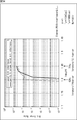
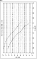
- An error rate obtained by the simulation is a diagram showing the relationship between the Doppler frequency f d of the flutter.
- An error rate obtained by the simulation is a diagram showing the relationship between the Doppler frequency f d of the flutter.
- 3 is a block diagram illustrating a configuration example of an LDPC encoder 115.
- FIG. 5 is a flowchart for explaining processing of an LDPC encoder 115.
- Fig. 38 is a diagram illustrating an example of a parity check matrix initial value table with the code rate 1/4 and the code length 16200. It is a figure explaining the method of calculating
- FIG. It is a figure which shows the example of the check matrix initial value table of 16k code
- symbol of r 10/15. It is a figure which shows the example of the Tanner graph of the ensemble of a degree sequence that column weight is 3 and row weight is 6.
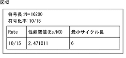
- FIG. It is a figure which shows the example of the Tanner graph of a multi-edge type ensemble. It is a figure which shows the minimum cycle length and performance threshold value of the check matrix of 16k code
- symbol of r 10/15. It is a figure explaining the check matrix of 16k code
- symbol of r 10/15. It is a figure explaining the check matrix of 16k code
- symbol of r 10/15. It is a figure which shows the simulation result of the simulation which measures BER / FER.
- FIG. 3 is a block diagram illustrating a configuration example of a receiving device 12.
- FIG. It is a block diagram which shows the structural example of the bit deinterleaver 165.
- FIG. 12 is a flowchart for describing processing performed by a demapper 164, a bit deinterleaver 165, and an LDPC decoder 166. It is a figure which shows the example of the check matrix of a LDPC code. It is a figure which shows the matrix (conversion test matrix) which performed row substitution and column substitution to the check matrix. It is a figure which shows the conversion test matrix divided
- FIG. 3 is a block diagram illustrating a configuration example of an LDPC decoder 166.
- FIG. It is a figure explaining the process of the multiplexer 54 which comprises the bit deinterleaver 165.
- FIG. It is a figure explaining the process of the column twist deinterleaver.
- It is a block diagram which shows the other structural example of the bit deinterleaver 165.
- FIG. It is a block diagram which shows the 1st structural example of the receiving system which can apply the receiving device.
- It is a block diagram which shows the 2nd structural example of the receiving system which can apply the receiving device.
- FIG. 18 is a block diagram illustrating a configuration example of an embodiment of a computer to which the present technology is applied.
- LDPC code is a linear code and does not necessarily need to be binary, but here it will be described as being binary.
- LDPC code is characterized by the fact that the parity check matrix that defines the LDPC code is sparse.
- a sparse matrix is a matrix in which the number of “1” s in the matrix is very small (a matrix in which most elements are 0).
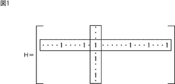
- FIG. 1 is a diagram illustrating an example of a parity check matrix H of an LDPC code.
- the weight of each column (column weight) (the number of “1”) (weight) is “3”, and the weight of each row (row weight) is “6”. .
- a generator matrix G is generated based on the check matrix H, and the generator matrix G is multiplied by binary information bits to generate a codeword (LDPC code). ) Is generated.
- the generator matrix G is a K ⁇ N matrix
- the encoding device multiplies the generator matrix G by a bit string (vector u) of information bits made up of K bits to generate a code made up of N bits.
- Generate the word c ( uG).
- the code word (LDPC code) generated by this encoding device is received on the receiving side via a predetermined communication path.
- LDPC code decoding is an algorithm proposed by Gallager called probabilistic decoding (Probabilistic Decoding), consisting of variable nodes (also called message nodes) and check nodes (check nodes). This can be done by a message passing algorithm based on belief propagation on a so-called Tanner graph.
- the variable node and the check node are also simply referred to as nodes as appropriate.
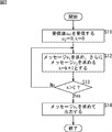
- FIG. 2 is a flowchart showing a procedure for decoding an LDPC code.
- a real value (reception LLR) expressing the “0” likelihood of the value of the i-th code bit of the LDPC code (1 codeword) received on the receiving side as a log likelihood ratio as appropriate. ) Is also referred to as a received value u 0i . Further, a message output from the check node is u j and a message output from the variable node is v i .
- step S11 the LDPC code is received, the message (check node message) u j is initialized to “0”, and the counter of the iterative process is used.
- the variable k taking the integer of is initialized to “0”, and the process proceeds to step S12.
- step S12 a message (variable node message) v i is obtained by performing the calculation (variable node calculation) shown in Expression (1) based on the received value u 0i obtained by receiving the LDPC code.
- the message u j is obtained by performing the calculation (check node calculation) shown in Expression (2).
- Equation (1) and Equation (2) can be arbitrarily selected to indicate the number of “1” s in the vertical direction (column) and horizontal direction (row) of the parity check matrix H, respectively.
- variable node calculation of Expression (1) the message input from the edge (line connecting the variable node and the check node) to which the message is to be output, respectively.
- the computation range is 1 to d v -1 or 1 to d c -1.
- the check node calculation of equation (2) actually creates a table of function R (v 1 , v 2 ) shown in equation (3) defined by one output for two inputs v 1 and v 2 in advance. In addition, this is performed by using it continuously (recursively) as shown in Equation (4).
- step S12 the variable k is further incremented by “1”, and the process proceeds to step S13.
- step S13 it is determined whether or not the variable k is larger than a predetermined iterative decoding count C. If it is determined in step S13 that the variable k is not greater than C, the process returns to step S12, and thereafter the same processing is repeated.
- step S13 determines whether the variable k is larger than C. If it is determined in step S13 that the variable k is larger than C, the process proceeds to step S14, and a message v i as a decoding result to be finally output is obtained by performing the calculation shown in equation (5). And the LDPC code decoding process ends.
- equation (5) is performed using messages u j from all branches connected to the variable node.
- FIG. 3 is a diagram illustrating an example of a parity check matrix H of a (3, 6) LDPC code (coding rate 1/2, code length 12).
- the column weight is 3 and the row weight is 6, as in FIG.
- FIG. 4 is a diagram showing a Tanner graph of the check matrix H in FIG.
- a plus “+” represents a check node
- Check nodes and variable nodes correspond to the rows and columns of the parity check matrix H, respectively.
- the connection between the check node and the variable node is an edge, and corresponds to “1” of the check matrix element.
- the branch represents that the sign bit corresponding to the variable node has a constraint condition corresponding to the check node.
- FIG. 5 is a diagram showing variable node calculation performed in the variable node.
- the message v i corresponding to the branch to be calculated is the variable node of the formula (1) using the messages u 1 and u 2 from the remaining branches connected to the variable node and the received value u 0i. It is obtained by calculation. Messages corresponding to other branches are obtained in the same manner.
- FIG. 6 is a diagram showing a check node calculation performed in the check node.
- sign (x) is 1 when x ⁇ 0, and ⁇ 1 when x ⁇ 0.
- Equation (6) can be transformed into Equation (7).
- the message u j corresponding to the branch to be calculated is the messages v 1 , v 2 , v 3 , v 4 , v from the remaining branches connected to the check node. It is obtained by the check node calculation of Equation (7) using 5 . Messages corresponding to other branches are obtained in the same manner.
- ⁇ (x) and ⁇ ⁇ 1 (x) are mounted on hardware, they may be mounted using a LUT (Look Up Table), but both are the same LUT.
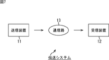
- FIG. 7 shows a transmission system to which the present technology is applied (a system is a logical collection of a plurality of devices, regardless of whether or not each component device is in the same housing). It is a figure which shows the structural example of embodiment.
- the transmission system includes a transmission device 11 and a reception device 12.
- the transmission device 11 transmits (broadcasts) (transmits) a television broadcast program, for example. That is, the transmission device 11 encodes target data to be transmitted, such as image data and audio data as a program, into an LDPC code, for example, a satellite line, a terrestrial wave, a cable (wired line), or the like. It transmits via the communication path 13.
- target data to be transmitted such as image data and audio data as a program
- an LDPC code for example, a satellite line, a terrestrial wave, a cable (wired line), or the like. It transmits via the communication path 13.
- the receiving device 12 receives the LDPC code transmitted from the transmitting device 11 via the communication path 13, decodes it into the target data, and outputs it.
- the LDPC code used in the transmission system of FIG. 7 exhibits extremely high capability in an AWGN (Additive White Gaussian Noise) channel.
- AWGN Additional White Gaussian Noise
- a burst error or erasure may occur in the communication path 13.
- D / U Desiredsito UndesiredirRatio
- Desired main path power
- a burst error may occur due to the state of the wiring from the receiving unit (not shown) such as an antenna that receives a signal from the transmitting device 11 to the receiving device 12 on the receiving device 12 side or the instability of the power supply of the receiving device 12. May occur.
- the code bit (received value u 0i of the LDPC code) at the variable node corresponding to the column of the parity check matrix H and thus the code bit of the LDPC code. Since the variable node operation of the expression (1) with the addition of) is performed, if an error occurs in the sign bit used for the variable node operation, the accuracy of the required message is reduced.
- the check node performs the check node calculation of Expression (7) using the message obtained by the variable node connected to the check node, so that a plurality of connected variable nodes ( When the number of check nodes in which the error (including erasure) of the code bits of the LDPC code corresponding to) simultaneously increases, the decoding performance deteriorates.
- the check node sends a message with an equal probability of a probability of 0 and a probability of 1 to all the variable nodes. return.
- a check node that returns an equiprobable message does not contribute to one decoding process (one set of variable node calculation and check node calculation), and as a result, requires a large number of repetitions of the decoding process. As a result, the decoding performance deteriorates, and the power consumption of the receiving apparatus 12 that decodes the LDPC code increases.
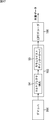
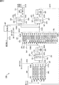
- FIG. 8 is a block diagram illustrating a configuration example of the transmission device 11 of FIG.
- one or more input streams (Input Streams) as target data are supplied to a Mode Adaptation / Multiplexer 111.
- the mode adaptation / multiplexer 111 performs processing such as mode selection and multiplexing of one or more input streams supplied thereto as necessary, and supplies the resulting data to a padder 112. .
- the padder 112 performs necessary zero padding (Null insertion) on the data from the mode adaptation / multiplexer 111 and supplies the resulting data to the BB scrambler 113.
- the BB scrambler 113 subjects the data from the padder 112 to BB scramble (Base-Band Scrambling), and supplies the resulting data to a BCH encoder (BCH encoder) 114.
- BCH encoder BCH encoder
- the BCH encoder 114 BCH-encodes the data from the BB scrambler 113, and supplies the resulting data to an LDPC encoder 115 as LDPC target data that is an LDPC encoding target.
- the LDPC encoder 115 performs LDPC encoding on the LDPC target data from the BCH encoder 114 according to a parity check matrix in which a parity matrix that is a part corresponding to the parity bits of the LDPC code has a staircase structure. Output LDPC code as information bits.
- the LDPC encoder 115 sets the LDPC target data to the LDPC (corresponding to the check matrix) defined in a predetermined standard such as DVB-S.2, DVB-T.2, or DVB-C.2.
- LDPC encoding is performed to encode a code, a predetermined LDPC code (corresponding to the parity check matrix), and the resulting LDPC code is output.
- the LDPC code defined in the DVB-S.2, DVB-T.2, and DVB-C.2 standards is an IRA (Irregular Repeat Accumulate) code, and the parity in the parity check matrix of the LDPC code
- the matrix has a staircase structure. The parity matrix and the staircase structure will be described later.
- IRA codes for example, “Irregular Repeat-Accumulate Codes,” H. Jin, A. Khandekar, and R. J. McEliece, in Proceedings of 2nd International Symposium on Turbo codes and Related Topics-8 , Sept. 2000.
- the LDPC code output from the LDPC encoder 115 is supplied to a bit interleaver 116.
- the bit interleaver 116 performs bit interleaving described later on the LDPC code from the LDPC encoder 115 and supplies the LDPC code after the bit interleaving to the mapper 117.
- the mapper 117 maps the LDPC code from the bit interleaver 116 to a signal point representing one symbol of orthogonal modulation in units of one or more code bits (symbol unit) of the LDPC code and performs orthogonal modulation (multiple modulation). Value modulation).
- the mapper 117 converts the LDPC code from the bit interleaver 116 into an IQ plane (IQ constellation) defined by an I axis representing an I component in phase with the carrier and a Q axis representing a Q component orthogonal to the carrier.
- the quadrature modulation is performed by mapping to signal points determined by the modulation method for performing the quadrature modulation of the LDPC code.
- a modulation method of the orthogonal modulation performed by the mapper 117 for example, a modulation method defined in the DVB-S.2, DVB-T.2, DVB-C.2 standard, etc., and other modulations.
- System ie, BPSK (Binary Phase Shift Keying), QPSK (Quadrature Phase Shift Keying), 8PSK (Phase-Shift Keying), 16APSK (Amplitude Phase Shift-Keying), 32APSK, 16QAM (Quadrature Amplitude Modulation), 64QAM , 256QAM, 1024QAM, 4096QAM, 4PAM (Pulse Amplitude Modulation), etc.
- which modulation method is used for orthogonal modulation is set in advance in accordance with, for example, the operation of the operator of the transmission apparatus 11.
- Data obtained by processing in the mapper 117 (mapping result obtained by mapping symbols to signal points) is supplied to a time interleaver 118.
- the time interleaver 118 performs time interleaving (interleaving in the time direction) on the data from the mapper 117 in units of symbols, and the resulting data is converted into SISO / MISO encoders (SISO / MISO (Single / Input / Single / Output / Multiple). Input Single Output) encoder) 119.
- SISO / MISO encoders SISO / MISO encoders
- the SISO / MISO encoder 119 performs space-time coding on the data from the time interleaver 118 and supplies it to a frequency interleaver 120.
- the frequency interleaver 120 performs frequency interleaving (interleaving in the frequency direction) on a symbol-by-symbol basis for the data from the SISO / MISO encoder 119 and supplies the data to a frame builder / resource allocation unit (Frame Builder & Resource Allocation) 131.
- a frame builder / resource allocation unit Fre Builder & Resource Allocation
- the BCH encoder 121 is supplied with control data (signalling) for transmission control such as BB signaling (Base Band Signaling) (BB Header).
- BB signaling Basic Band Signaling
- the BCH encoder 121 performs BCH encoding on the control data supplied thereto in the same manner as the BCH encoder 114, and supplies the resulting data to the LDPC encoder 122.
- the LDPC encoder 122 performs LDPC encoding on the data from the BCH encoder 121 as LDPC target data in the same manner as the LDPC encoder 115, and supplies the resulting LDPC code to the mapper 123.
- the mapper 123 maps the LDPC code from the LDPC encoder 122 to a signal point that represents one symbol of orthogonal modulation in units of one or more code bits (symbol unit) of the LDPC code. Then, quadrature modulation is performed, and data obtained as a result is supplied to the frequency interleaver 124.
- the frequency interleaver 124 performs frequency interleaving on the data from the mapper 123 in units of symbols and supplies the data to the frame builder / resource allocation unit 131.
- the frame builder / resource allocation unit 131 inserts pilot symbols at necessary positions of the data (symbols) from the frequency interleavers 120 and 124, and from the resulting data (symbols), a predetermined number
- a frame composed of a number of symbols for example, a PL (Physical Layer) frame, a T2 frame, a C2 frame, etc.
- OFDM generation OFDM generation
- the OFDM generation unit 132 generates an OFDM signal corresponding to the frame from the frame from the frame builder / resource allocation unit 131, and transmits the OFDM signal via the communication path 13 (FIG. 7).
- the transmission apparatus 11 is configured without providing some of the blocks illustrated in FIG. 8 such as the time interleaver 118, the SISO / MISO encoder 119, the frequency interleaver 120, and the frequency interleaver 124, for example. Can do.
- FIG. 9 shows a configuration example of the bit interleaver 116 of FIG.
- the bit interleaver 116 has a function of interleaving data, and includes a parity interleaver 23, a column twist interleaver 24, and a demultiplexer (DEMUX) 25. Note that the bit interleaver 116 can be configured without providing one or both of the parity interleaver 23 and the column twist interleaver 24.
- the parity interleaver 23 performs parity interleaving for interleaving the parity bits of the LDPC code from the LDPC encoder 115 to other parity bit positions, and supplies the LDPC code after the parity interleaving to the column twist interleaver 24.
- the column twist interleaver 24 performs column twist interleaving on the LDPC code from the parity interleaver 23 and supplies the LDPC code after the column twist interleaving to the demultiplexer 25.
- the LDPC code is transmitted in the mapper 117 of FIG. 8 by mapping one or more code bits of the LDPC code to a signal point representing one symbol of orthogonal modulation.
- the column twist interleaver 24 uses a parity interleaver 23 so that a plurality of code bits of the LDPC code corresponding to 1 in any one row of the parity check matrix used in the LDPC encoder 115 are not included in one symbol. As rearrangement processing for rearranging the code bits of the LDPC code, for example, column twist interleaving as described later is performed.
- the demultiplexer 25 obtains an LDPC code with enhanced resistance to AWGN or the like by performing a replacement process for replacing the positions of two or more code bits of the LDPC code as a symbol for the LDPC code from the column twist interleaver 24. Then, the demultiplexer 25 supplies two or more code bits of the LDPC code obtained by the replacement process to the mapper 117 (FIG. 8) as a symbol.
- FIG. 10 shows a parity check matrix H used for LDPC encoding by the LDPC encoder 115 of FIG.
- LDGM Low-Density Generation Matrix
- the number of information bits and the number of parity bits in the code bits of one LDPC code are referred to as information length K and parity length M, respectively, and one LDPC.
- the information length K and the parity length M for an LDPC code having a certain code length N are determined by the coding rate.
- the parity check matrix H is an M ⁇ N matrix with rows ⁇ columns. Then, the information matrix H A, becomes the matrix of M ⁇ K, the parity matrix H T is a matrix of M ⁇ M.
- DVB-S.2 shows a parity matrix H T of the parity DVB-T.2, and parity check matrix H of an LDPC code prescribed in DVB-C.2 standards.
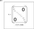
- DVB-T.2 like parity matrix H T of the parity check matrix H of an LDPC code of which is specified in the Standard, as shown in FIG. 11, first element is, so to speak a matrix of step structure arranged stepwise (lower bidiagonal matrix).
- the row weight of the parity matrix H T is 1 for the first row and 2 for all the remaining rows.
- the column weight is 1 for the last column and 2 for all the remaining columns.
- LDPC codes of the check matrix H the parity matrix H T has a staircase structure can be using the check matrix H, readily produced.
- an LDPC code (one codeword), together represented by a row vector c, and column vector obtained by transposing the row vector is represented as c T. Further, in the row vector c which is an LDPC code, the information bit portion is represented by the row vector A, and the parity bit portion is represented by the row vector T.
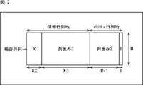
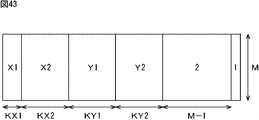
- FIG. 12 is a diagram for explaining a parity check matrix H of an LDPC code defined in a standard such as DVB-T.2.
- the column weight is X, and for the subsequent K3 column, the column weight is 3, and then For the M-1 column, the column weight is 2, and for the last column, the column weight is 1.
- KX + K3 + M-1 + 1 is equal to the code length N.
- FIG. 13 is a diagram showing the number of columns KX, K3, and M, and the column weight X for each coding rate r of the LDPC code defined in the DVB-T.2 standard and the like.
- Standards such as DVB-T.2 specify LDPC codes with code length N of 64800 bits and 16200 bits.
- LDPC code having a code length N of 64,800 bits 11 coding rates (nominal rates) 1/4, 1/3, 2/5, 1/2, 3/5, 2/3, 3 / 4, 4/5, 5/6, 8/9, and 9/10 are defined, and for an LDPC code having a code length N of 16200 bits, 10 coding rates 1/4, 1/3, 2/5, 1/2, 3/5, 2/3, 3/4, 4/5, 5/6, and 8/9 are specified.
- the code length N of 64800 bits is also referred to as 64k bits
- the code length N of 16200 bits is also referred to as 16k bits.
- the error rate tends to be lower for code bits corresponding to columns having a larger column weight of the check matrix H.
- the column weight on the head side (left side) tends to be large.
- the LDPC code corresponding to H the first code bit tends to be more resistant to errors (tolerant to errors), and the last code bit tends to be weaker to errors.
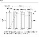
- FIG. 14 shows an example of arrangement of 16 symbols (corresponding signal points) on the IQ plane when 16QAM is performed by the mapper 117 of FIG.
- a in FIG. 14 shows a DVB-T.2 16QAM symbol (corresponding signal point).
- the 16 symbols are arranged so that the I direction ⁇ Q direction is a 4 ⁇ 4 square shape with the origin of the IQ plane as the center.
- bit y i + 1 bit from the most significant bit in the bit string represented by one symbol is represented as bit y i
- the four bits represented by one symbol of 16QAM are bit y 0 in order from the most significant bit. , y 1 , y 2 , y 3 .
- 4 code bits of the LDPC code is (symbolized) into 4-bit y 0 to y 3 symbol (symbol value).
- FIG. 14B shows bit boundaries for each of 4 bits (hereinafter also referred to as symbol bits) y 0 to y 3 represented by a 16QAM symbol.
- the symbol bit y i represented by a symbol is more likely to be erroneous (lower error probability) the more symbols are away from the bit boundary, and more likely to be error (higher error probability) as there are more symbols near the bit boundary.
- strong to errors a bit that is hard to error
- weak to errors a bit that is easy to error
- 4 symbol bits y 0 to y 3 of a 16QAM symbol 4 symbol bits y 0 to y 3 of a 16QAM symbol .
- the most significant symbol bit y 0 and the second symbol bit y 1 are strong bits
- the third symbol bit y 2 and the fourth symbol bit y 3 are weak bits. .
- 15 to 17 show examples of arrangement of 64 symbols (corresponding signal points) on the IQ plane when 64QAM is performed by the mapper 117 of FIG. 8, that is, DVB-T.2 16QAM. Symbols are shown.
- One symbol bit of 64QAM can be expressed as bits y 0 , y 1 , y 2 , y 3 , y 4 , y 5 in order from the most significant bit.
- the 6 code bits of the LDPC code is the symbol bits y 0 no 6-bit to the symbol y 5.
- FIG. 15 shows bit boundaries for the most significant symbol bit y 0 and the second symbol bit y 1 among the symbol bits y 0 to y 5 of the 64QAM symbol, and FIG. th symbol bit y 2, the bit boundaries for the fourth symbol bit y 3, respectively, FIG. 17, the fifth symbol bit y 4, the bit boundaries for the sixth symbol bit y 5, respectively, each Show.
- the symbol bits y 0 of the uppermost bit boundaries for the second symbol bit y 1, respectively, has at one place. Also, as shown in FIG. 16, there are two bit boundaries for each of the third symbol bit y 2 and the fourth symbol bit y 3 , and as shown in FIG. 17, the fifth symbol bit There are four bit boundaries for bit y 4 and sixth symbol bit y 5 .
- the most significant symbol bit y 0 and the second symbol bit y 1 are strong bits, and the third symbol bits y 2 and 4 th symbol bit y 3 has become a strong bit to the next.
- the fifth symbol bit y 4 and the sixth symbol bit y 5 are weak bits.
- FIG. 18 shows an example of arrangement of four symbols (corresponding signal points) on the IQ plane when a satellite channel is employed as the communication path 13 (FIG. 7) and QPSK is performed by the mapper 117 of FIG. That is, for example, it is a diagram illustrating a signal point arrangement of DVB-S.2 QPSK.
- a symbol is mapped to one of four signal points on a circle with a radius ⁇ of 1 centered on the origin on the IQ plane.
- FIG. 19 shows an example of arrangement of 8 symbols on the IQ plane when a satellite channel is used as the communication path 13 (FIG. 7) and 8PSK is performed by the mapper 117 of FIG. 8, that is, for example, DVB- It is a figure which shows 8PSK signal point arrangement
- DVB-S.2 8PSK a symbol is mapped to one of eight signal points on the circumference of a circle with a radius ⁇ of 1 centered on the origin on the IQ plane.
- FIG. 20 shows an example of arrangement of 16 symbols on the IQ plane when 16APSK is performed by the mapper 117 of FIG. 8 using a satellite channel as the communication path 13 (FIG. 7), for example, DVB- It is a figure which shows the signal point arrangement
- Fig. 20A shows DVB-S.2 16APSK constellation.
- a symbol has four signal points on the circumference of a circle with a radius of R 1 centered at the origin on the IQ plane, and a radius of R 2 (> R 1 ).
- the 12 signal points on the circumference of the circle are mapped to any one of 16 signal points in total.
- the ratio ⁇ between the radii R 2 and R 1 differs for each coding rate.
- FIG. 21 shows an example of arrangement of 32 symbols on the IQ plane when a satellite channel is employed as the communication path 13 (FIG. 7) and 32APSK is performed by the mapper 117 of FIG. 8, that is, for example, DVB- It is a figure which shows the signal point arrangement
- 21A shows the constellation of DVB-S.2 32APSK.
- a symbol consists of four signal points on the circumference of a circle with a radius of R 1 centered at the origin on the IQ plane and a circle with a radius of R 2 (> R 1 ). 12 signal points on the circumference and 16 signal points on the circumference of the circle having a radius of R 3 (> R 2 ) are mapped to any one of 32 signal points in total.
- the ratio gamma 1 and radius R 2 and R 1 and the radius R 3 and the ratio gamma 2 and R 1 are different for each code rate.
- the LDPC code output from the LDPC encoder 115 includes a code bit that is resistant to errors and a code bit that is vulnerable to errors.
- the symbol bits of the orthogonal modulation symbol performed by the mapper 117 include a strong bit and a weak bit.
- FIG. 22 is a diagram for explaining the processing of the demultiplexer 25 in FIG.
- a in FIG. 22 shows a functional configuration example of the demultiplexer 25.
- the demultiplexer 25 includes a memory 31 and a replacement unit 32.
- the memory 31 is supplied with the LDPC code from the LDPC encoder 115.
- the memory 31 has a storage capacity for storing mb bits in the row (horizontal) direction and N / (mb) bits in the column (vertical) direction, and the LDPC supplied thereto The sign bit of the code is written in the column direction, read in the row direction, and supplied to the switching unit 32.
- N information length K + parity length M
- m represents the number of code bits of an LDPC code that is one symbol
- b is a predetermined positive integer, which is a multiple used to multiply m by an integer.
- the demultiplexer 25 uses the sign bit of the LDPC code as a symbol in a unit of a predetermined number of bits m (symbolizes), and the multiple b represents the number of symbols that the demultiplexer 25 obtains by so-called symbolization. .
- FIG. 22A shows a configuration example of the demultiplexer 25 in the case where the modulation scheme is 64QAM or the like that maps symbols to any of 64 signal points. Therefore, the sign bit of the LDPC code that becomes one symbol The number of bits m is 6 bits.
- the multiple b is 1. Therefore, the memory 31 has a storage capacity of N / (6 ⁇ 1) ⁇ (6 ⁇ 1) bits in the column direction ⁇ row direction.
- the storage area of the memory 31 extending in the column direction and having a 1-bit row direction is hereinafter referred to as a column as appropriate.
- the code bits of the LDPC code are written from the top to the bottom (column direction) of the columns constituting the memory 31 from the left to the right columns.
- the sign bit When writing of the sign bit is completed to the bottom of the rightmost column, the sign bit is changed in units of 6 bits (mb bits) in the row direction from the first row of all the columns constituting the memory 31. It is read out and supplied to the replacement unit 32.
- the exchanging unit 32 performs an exchanging process of exchanging the positions of the 6-bit code bits from the memory 31, and the 6 bits obtained as a result are replaced with 6 symbol bits y 0 , y 1 , y 2 , y representing one symbol of 64QAM. Output as 3 , y 4 , y 5 .
- mb bits (6 bits in this case) of code bits are read from the memory 31 in the row direction, and the i-th bit from the most significant bit of the mb bits of code bits read from the memory 31 is read out.
- bit b i the 6-bit code bits read out from the memory 31 in the row direction are bits b 0 , It can be expressed as b 1 , b 2 , b 3 , b 4 , b 5 .
- the sign bit in the direction of bit b 0 is a sign bit that is resistant to errors in the relationship of the column weights described in FIGS. 12 and 13, and the sign bit in the direction of bit b 5 is a sign that is vulnerable to errors. It is a bit.
- the 6-bit code bits b 0 to b 5 from the memory 31 are assigned the error-sensitive code bits to the strong bits of the 64QAM 1-symbol symbol bits y 0 to y 5. As shown in the figure, it is possible to perform an exchange process for exchanging the positions of the 6-bit code bits b 0 to b 5 from the memory 31.
- FIG. 22B shows the first replacement method
- FIG. 22C shows the second replacement method
- FIG. 22D shows the third replacement method.
- FIG. 23 shows 64QAM or the like in which the modulation scheme maps a symbol to one of 64 signal points (therefore, the number m of code bits of an LDPC code mapped to one symbol is 6 as in FIG.
- a configuration example of the demultiplexer 25 when the multiple b is 2) and a fourth replacement method are shown.
- FIG. 23A shows the order of writing LDPC codes to the memory 31.
- the code bits of the LDPC code are written from the top to the bottom (column direction) of the columns constituting the memory 31. Is called.
- the exchanging unit 32 performs an exchanging process of exchanging the positions of the 12-bit code bits from the memory 31 by the fourth exchanging method, and the 12 bits obtained as a result represent 2 symbols (b symbols) of 64QAM. 12 bits, that is, 6 symbol bit y 0 representing a symbol of 64QAM, y 1, y 2, y 3, y 4, and y 5, 6 symbol bits y 0 representing the next one symbol, y 1, y 2 , y 3 , y 4 , y 5
- B in FIG. 23 shows a fourth replacement method of the replacement processing by the replacement unit 32 in A of FIG.
- mb code bits are allocated to mb symbol bits of b consecutive symbols.
- bit (symbol bit) y i the (i + 1) -th bit from the most significant bit of the mb bit of b consecutive symbols.
- parity interleaving by the parity interleaver 23 in FIG. 9 will be described with reference to FIGS.
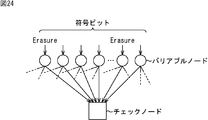
- FIG. 24 shows (part of) a Tanner graph of a parity check matrix of an LDPC code.
- variable nodes corresponding code bits
- all of the check nodes connected to the check node are connected.
- a message having a probability that the value is 0 and the probability that the value is 1 is returned to the variable node. For this reason, if a plurality of variable nodes connected to the same check node simultaneously become erasures or the like, the decoding performance deteriorates.
- LDPC encoder 115 of FIG. 8 outputs, LDPC code prescribed in standards such as DVB-S.2 is IRA code, parity matrix H T of the parity check matrix H, as shown in FIG. 11 It has a staircase structure.
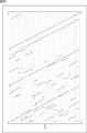
- FIG. 25 shows a parity matrix H T having a staircase structure and a Tanner graph corresponding to the parity matrix H T.
- a in FIG. 25 shows a parity matrix H T having a staircase structure
- B in FIG. 25 shows a Tanner graph corresponding to the parity matrix H T in A in FIG.
- parity matrix H T has a staircase structure, in each row (except the first row) first element is adjacent. Therefore, in the Tanner graph of the parity matrix H T, the value of the parity matrix H T corresponding to the columns of two adjacent elements are set to 1, the two variable nodes adjacent, connected to the same check node Yes.
- the parity interleaver 23 (FIG. 9) performs parity interleaving for interleaving the parity bits of the LDPC code from the LDPC encoder 115 to the positions of other parity bits in order to prevent the above-described degradation in decoding performance. .
- Figure 26 illustrates a parity matrix H T of the parity check matrix H corresponding to the LDPC code after parity interleave to the parity interleaver 23 of FIG. 9 is performed.
- the information matrix H A of the parity check matrix H corresponding to the LDPC code defined in the DVB-S.2 standard and the like output from the LDPC encoder 115 has a cyclic structure.
- a cyclic structure is a structure in which a column matches a cyclic shift of another column.For example, for each P column, the position of 1 in each row of the P column is the first of the P column.
- a structure in which the column is cyclically shifted in the column direction by a value proportional to the value q obtained by dividing the parity length M is also included.
- the P column in the cyclic structure is referred to as the number of columns in the cyclic structure unit as appropriate.
- LDPC codes having a code length N of 64800 bits and 16200 bits as LDPC codes defined in the DVB-S.2 standard.
- N 64800 bits
- 16200 bits 16200 bits
- the number P of columns in the unit of the cyclic structure is defined as 360, which is one of the divisors excluding 1 and M among the divisors of the parity length M.
- the parity interleaver 23 sets the information length to K, sets x to an integer between 0 and less than P, and sets y to an integer between 0 and less than q.
- the K + qx + y + 1-th code bit is interleaved at the position of the K + Py + x + 1-th code bit.
- the K + qx + y + 1-th code bit and the K + Py + x + 1-th code bit are both the K + 1-th code bit and the subsequent parity bits, and are therefore parity bits. According to interleaving, the position of the parity bit of the LDPC code is moved.
- variable nodes connected to the same check node are separated by the number of columns P of the cyclic structure unit, that is, 360 bits here, so the burst length is In the case of less than 360 bits, it is possible to avoid a situation in which a plurality of variable nodes connected to the same check node cause an error at the same time, and as a result, it is possible to improve resistance to burst errors.
- the LDPC code after parity interleaving that interleaves the K + qx + y + 1-th code bit at the position of the K + Py + x + 1-th code bit is K + qx + of the original parity check matrix H.
- the pseudo cyclic structure means a structure in which a part except for a part has a cyclic structure.
- the transform parity check matrix obtained by performing column replacement equivalent to parity interleaving on the parity check matrix of the LDPC code specified in the DVB-S.2 standard, etc. is 360 rows by 360 columns.
- the part the shift matrix described later
- only one element of 1 is present (it is an element of 0), and in this respect, it is not a (complete) cyclic structure but a pseudo cyclic structure.
- the conversion check matrix in FIG. 26 replaces the original check matrix H with column replacement corresponding to parity interleaving, as well as row replacement so that the conversion check matrix is configured with a configuration matrix described later. (Row replacement) is also applied to the matrix.
- LDPC 8 transmits one or more code bits of the LDPC code as one symbol. That is, for example, when 2 bits of code bits are used as one symbol, QPSK is used as a modulation system, for example. When 4 bits of code bits are used as 1 symbol, a modulation system is used. For example, 16APSK or 16QAM is used.
- the information matrix HA has a cyclic structure
- the parity matrix H T Has a staircase structure.
- FIG. 27 shows a conversion check matrix
- a in FIG. 27 shows a conversion parity check matrix of a parity check matrix H of an LDPC code having a code length N of 64,800 bits and a coding rate (r) of 3/4.
- FIG. 27B shows processing performed by the demultiplexer 25 (FIG. 9) for the LDPC code of the conversion check matrix of FIG. 27A, that is, the LDPC code after parity interleaving.
- the modulation method is a method of mapping symbols to any of 16 signal points, such as 16APSK or 16QAM
- the four columns constituting the memory 31 of the demultiplexer 25 are subjected to parity interleaving.
- the sign bit of the LDPC code is written in the column direction.
- the sign bit written in the column direction in the four columns constituting the memory 31 is read out in units of 4 bits in the row direction to become one symbol.
- 4-bit code bits B 0 , B 1 , B 2 , and B 3 that are one symbol are code bits corresponding to 1 in any one row of the conversion check matrix of A in FIG.
- the variable nodes corresponding to the sign bits B 0 , B 1 , B 2 , and B 3 are connected to the same check node.
- the column twist interleaver 24 performs a process after parity interleaving from the parity interleaver 23 so that a plurality of code bits corresponding to 1 in any one row of the conversion check matrix are not included in one symbol. Column twist interleaving is performed to interleave the code bits of the LDPC code.
- FIG. 28 is a diagram for explaining column twist interleaving.
- FIG. 28 shows the memory 31 (FIGS. 22 and 23) of the demultiplexer 25.
- the memory 31 stores N / (mb) bits in the column (vertical) direction and has a storage capacity for storing mb bits in the row (horizontal) direction.
- Consists of The column twist interleaver 24 performs column twist interleaving by controlling the write start position when writing the code bits of the LDPC code in the column direction and reading in the row direction to the memory 31.
- a plurality of code bits, which are read as one symbol, are read out in the row direction by appropriately changing the write start position at which code bit writing is started for each of a plurality of columns.
- the sign bit corresponding to 1 in any one row of the conversion parity check matrix is prevented (a plurality of code bits corresponding to 1 in any one row of the parity check matrix are not included in the same symbol.
- the code bits of the LDPC code are rearranged).
- the column twist interleaver 24 writes the code bits of the LDPC code from the top to the bottom (column direction) of the four columns constituting the memory 31 (instead of the demultiplexer 25 in FIG. 22). Towards the direction column.
- the column twist interleaver 24 starts from the first row of all the columns constituting the memory 31 in the row direction in units of 4 bits (mb bits).
- the code bit is read out and output to the switching unit 32 (FIGS. 22 and 23) of the demultiplexer 25 as an LDPC code after column twist interleaving.
- the address at the top (top) position of each column is 0 and the address at each position in the column direction is expressed as an integer in ascending order
- the starting position of writing is the position where the address is 0, the second column (from the left) is the starting position of writing, the address is the position 2, and the third column is the starting position of writing.
- the address is at position 4, and for the fourth column, the write start position is the position at address 7.
- the writing start position is other than the position where the address is 0
- the writing start position After writing the sign bit to the lowest position, it returns to the beginning (position where the address is 0), and the writing start position. Writing up to the position immediately before is performed. Thereafter, writing to the next (right) column is performed.
- FIG. 29 shows the number of columns of the memory 31 necessary for column twist interleaving and the writing of LDPC codes of 11 coding rates defined in the DVB-T.2 standard and having a code length N of 64800. The address of the starting position is shown for each modulation method.
- the write start position of the first column of the two columns of the memory 31 is the position where the address is 0, and the write start position of the second column is the position where the address is 2.
- the memory 31 is arranged in the row direction according to FIG. It has 4 columns for storing 2 ⁇ 2 bits and stores 64800 / (2 ⁇ 2) bits in the column direction.
- the first column write start position is the address 0 position
- the second column write start position is the address 2 position
- the third column The start position of writing in the column is the position where the address is 4
- the start position of writing in the fourth column is the position where the address is 7.
- the multiple b is 2.
- the memory 31 is arranged in the row direction according to FIG. It has four columns for storing 4 ⁇ 1 bits, and stores 64800 / (4 ⁇ 1) bits in the column direction.
- the first column write start position is the address 0 position
- the second column write start position is the address 2 position
- the write start position of the second column is the position where the address is 4
- the write start position of the fourth column is the position where the address is 7.
- the memory 31 is arranged in the row direction according to FIG. It has 8 columns for storing 4 ⁇ 2 bits and stores 64800 / (4 ⁇ 2) bits in the column direction.
- the first column write start position is the address 0 position
- the second column write start position is the address 0 position
- the start position of the second column is the position where the address is 2
- the start position of the fourth column is the position where the address is 4
- the start position of the fifth column is the position where the address is 4.
- the position and the start position of writing in the sixth column are the position where the address is 5
- the start position of writing in the seventh column is the position where the address is 7, and the starting position of the eighth column is The address is made with 7 positions, respectively.
- the memory 31 is arranged in the row direction according to FIG. It has 6 columns for storing 6 ⁇ 1 bits, and stores 64800 / (6 ⁇ 1) bits in the column direction.
- the first column write start position is the address 0 position
- the second column write start position is the address 2 position
- the first column write position is the address 5 position
- the fourth column write start position is the address 9 position
- the fifth column write start position is the address 10.
- the position and the position at the beginning of writing in the sixth column are the position where the address is 13, respectively.
- the memory 31 is arranged in the row direction according to FIG. It has 12 columns for storing 6 ⁇ 2 bits, and stores 64800 / (6 ⁇ 2) bits in the column direction.
- the first column write start position is the address 0 position
- the second column write start position is the address 0 position
- the start position of the second column is the position where the address is 2
- the start position of the fourth column is the position where the address is 2
- the start position of the fifth column is the position where the address is 3.
- the position and the start position of the 6th column are the position where the address is 4
- the start position of the 7th column is the position where the address is 4
- the start position of the 8th column is
- the position where the address is 5 and the start position of writing in the ninth column are the position where the address is 5,
- the start position of writing in the 10th column is the position where the address is 7 and the start position of writing in the 11th column.
- the position of is the position of address 8 and the 12th color Position of the writing start is set to the position whose address is 9, are respectively.
- the memory 31 is arranged in the row direction according to FIG. It has 8 columns for storing 8 ⁇ 1 bits and stores 64800 / (8 ⁇ 1) bits in the column direction.
- the first column write start position is the address 0 position
- the second column write start position is the address 0 position
- the start position of the second column is the position where the address is 2
- the start position of the fourth column is the position where the address is 4
- the start position of the fifth column is the position where the address is 4.
- the position and the start position of writing in the sixth column are the position where the address is 5
- the start position of writing in the seventh column is the position where the address is 7, and the starting position of the eighth column is The address is made with 7 positions, respectively.
- the memory 31 is arranged in the row direction according to FIG. It has 16 columns for storing 8 ⁇ 2 bits, and stores 64800 / (8 ⁇ 2) bits in the column direction.
- the first column write start position is the address 0 position
- the second column write start position is the address 2 position
- the start position of the second column is the position where the address is 2
- the start position of the fourth column is the position where the address is 2
- the start position of the fifth column is the address where the address is 2.
- the position and the start position of writing the sixth column are the position where the address is 3
- the start position of the seventh column is the position where the address is 7
- the start position of the eighth column is
- the position where the address is 15 and the start position of the 9th column are the position where the address is 16 and the start position where the 10th column is written are the position where the address is 20 and the start position of the 11th column.
- the positions of the address 22 and the 12th The start position of the program is the position where the address is 22, the start position of the 13th column is the position where the address is 27, and the start position of the 14th column is the position where the address is 27.
- the write start position of the 15th column is the position where the address is 28, and the write start position of the 16th column is the position where the address is 32.
- the memory 31 is arranged in the row direction according to FIG. It has 10 columns for storing 10 ⁇ 1 bits, and stores 64800 / (10 ⁇ 1) bits in the column direction.
- the first column write start position is the address 0 position
- the second column write start position is the address 3 position
- the first column write position is the address 6 position
- the fourth column write start position is the address 8 position
- the fifth column start position is the address 11
- the position and the start position of the 6th column are the position of the address 13
- the start position of the 7th column is the position of the address 15
- the start position of the 8th column is The address 17 position, the 9th column write start position, the address 18 position, and the 10th column write start position, the address 20 position, respectively.
- the memory 31 is arranged in the row direction according to FIG. It has 20 columns for storing 10 ⁇ 2 bits and stores 64800 / (10 ⁇ 2) bits in the column direction.
- the first column write start position is the address 0 position
- the second column write start position is the address 1 position
- the start position of the second column is the position where the address is 3
- the start position of the fourth column is the position where the address is 4
- the start position of the fifth column is the position where the address is 5.
- the position and the start position of writing in the sixth column are the position where the address is 6
- the start position of writing in the seventh column is the position where the address is 6
- the starting position of the eighth column is
- the position where the address is 9 and the start position of writing the ninth column are the position where the address is 13, and the start position of writing the tenth column is the position where the address is 14 and the start of writing the eleventh column.
- the position of is the position of address 14 and the 12th
- the start position of the program is the position where the address is 16, the start position of the 13th column is the position where the address is 21, and the start position of the 14th column is the position where the address is 21.
- the 15th column write start position is the address 23
- the 16th column write start position is the address 25 position
- the 17th column write start position is the address
- the 25th position and the 18th column start position are the address 26
- the 19th column start position are the address 28 and the 20th column start position. Is addressed with 30 positions, respectively.
- the memory 31 is arranged in the row direction according to FIG. It has 12 columns for storing 12 ⁇ 1 bits, and stores 64800 / (12 ⁇ 1) bits in the column direction.
- the first column write start position is the address 0 position
- the second column write start position is the address 0 position
- the start position of the second column is the position where the address is 2
- the start position of the fourth column is the position where the address is 2
- the start position of the fifth column is the position where the address is 3.
- the position and the start position of the 6th column are the position where the address is 4
- the start position of the 7th column is the position where the address is 4
- the start position of the 8th column is
- the position where the address is 5 and the start position of writing in the ninth column are the position where the address is 5,
- the start position of writing in the 10th column is the position where the address is 7 and the start position of writing in the 11th column.
- the position of is the position of address 8 and the 12th color Position of the writing start is set to the position whose address is 9, are respectively.
- the memory 31 is arranged in the row direction according to FIG. It has 24 columns for storing 12 ⁇ 2 bits, and stores 64800 / (12 ⁇ 2) bits in the column direction.
- the first column write start position is the address 0 position
- the second column write start position is the address 5 position
- the start position of the second column is the position where the address is 8
- the start position of the fourth column is the position where the address is 8
- the start position of the fifth column is the position where the address is 8.
- the position and the writing start position of the sixth column are the position where the address is 8
- the writing start position of the seventh column is the position of the address 10
- the writing start position of the eighth column is
- the position where the address is 10 and the start position of the 9th column are the position where the address is 10 and the start position where the 10th column is written are the position where the address is 12 and the start position of the 11th column.
- the position of is the position of address 13 and the 12th
- the starting position of the ram writing is the position of address 16, the starting position of the 13th column is the position of address 17, the starting position of the 14th column is the position of address 19
- the 15th column write start position is the address 21 position
- the 16th column write start position is the address 22 position
- the 17th column write start position is the address
- the position of 23 and the start position of writing of the 18th column are the position of address 26
- the start position of writing of the 19th column is the position of address 37 and the start position of writing of the 20th column.
- the position of the address 39 and the start position of the 21st column are the position of the address 40 and the start position of the 22nd column is the position of the address 41 and the position of the 23rd column.
- the address at the beginning of writing is 41 Position and, writing starting the 24th column position is set to the position whose address is 41, are respectively.
- FIG. 30 shows the number of columns of the memory 31 necessary for column twist interleaving and the LDPC code for each of the 10 coding rates with a code length N of 16200 defined in the DVB-T.2 standard. The address of the starting position is shown for each modulation method.
- the memory 31 is arranged in the row direction according to FIG. It has two columns that store 2 ⁇ 1 bits and stores 16200 / (2 ⁇ 1) bits in the column direction.
- the first column write start position is the address 0 position
- the second column write start position is the address 0 position. Is done.
- the memory 31 is arranged in the row direction according to FIG. It has four columns for storing 2 ⁇ 2 bits, and stores 16200 / (2 ⁇ 2) bits in the column direction.
- the first column write start position is the address 0 position
- the second column write start position is the address 2 position
- the write start position of the second column is the position where the address is 3
- the write start position of the fourth column is the position where the address is 3.
- the memory 31 is arranged in the row direction according to FIG. It has four columns for storing 4 ⁇ 1 bits, and stores 16200 / (4 ⁇ 1) bits in the column direction.
- the first column write start position is the address 0 position
- the second column write start position is the address 2 position
- the write start position of the second column is the position where the address is 3
- the write start position of the fourth column is the position where the address is 3.
- the memory 31 is arranged in the row direction according to FIG. It has 8 columns that store 4 ⁇ 2 bits, and stores 16200 / (4 ⁇ 2) bits in the column direction.
- the first column write start position is the address 0 position
- the second column write start position is the address 0 position
- the first column write start position is the address 0
- the fourth column write start position is the address 1 position
- the fifth column write start position is the address 7.
- the position and the start position of writing the sixth column are the position where the address is 20, the start position of the seventh column is the position where the address is 20, and the start position of the eighth column is Addresses are made with 21 positions, respectively.
- the memory 31 is arranged in the row direction according to FIG. It has 6 columns for storing 6 ⁇ 1 bits, and stores 16200 / (6 ⁇ 1) bits in the column direction.
- the first column write start position is the address 0 position
- the second column write start position is the address 0 position
- the start position of the second column is the position where the address is 2
- the start position of the fourth column is the position where the address is 3
- the start position of the fifth column is the position where the address is 7.
- the position and the position at the beginning of writing in the sixth column are set to the position where the address is 7, respectively.
- the memory 31 is arranged in the row direction according to FIG. It has 12 columns for storing 6 ⁇ 2 bits, and stores 16200 / (6 ⁇ 2) bits in the column direction.
- the first column write start position is the address 0 position
- the second column write start position is the address 0 position
- the start position of the second column is the position where the address is 0
- the start position of the fourth column is the position where the address is 2
- the start position of the fifth column is the position where the address is 2.
- the position of the start position of the 6th column is the position where the address is 2
- the start position of the 7th column is the position of the address 3
- the start position of the 8th column is
- the position where the address is 3 and the start position of the 9th column are the position where the address is 3 and the start position of the 10th column is the position where the address is 6 and the start of writing the 11th column.
- the position of is the position of address 7 and the 12th color Position of the writing start is set to the position whose address is 7, are respectively.
- the memory 31 is arranged in the row direction according to FIG. It has 8 columns for storing 8 ⁇ 1 bits, and stores 16200 / (8 ⁇ 1) bits in the column direction.
- the first column write start position is the address 0 position
- the second column write start position is the address 0 position
- the first column write start position is the address 0
- the fourth column write start position is the address 1 position
- the fifth column write start position is the address 7.
- the position and the start position of writing the sixth column are the position where the address is 20, the start position of the seventh column is the position where the address is 20, and the start position of the eighth column is Addresses are made with 21 positions, respectively.
- the memory 31 is arranged in the row direction according to FIG. It has 10 columns for storing 10 ⁇ 1 bits, and stores 16200 / (10 ⁇ 1) bits in the column direction.
- the first column write start position is the address 0 position
- the second column write start position is the address 1 position
- the start position of the second column is the position where the address is 2
- the start position of the fourth column is the position where the address is 2
- the start position of the fifth column is the position where the address is 3.
- the position and the start position of the 6th column are the position where the address is 3
- the start position of the 7th column is the position where the address is 4
- the start position of the 8th column is The address 4 position
- the 9th column write start position are the address 5 position
- the 10th column write start position are the address 7 position.
- the memory 31 is arranged in the row direction according to FIG. It has 20 columns for storing 10 ⁇ 2 bits, and stores 16200 / (10 ⁇ 2) bits in the column direction.
- the first column write start position is the address 0 position
- the second column write start position is the address 0 position
- the start position of the second column is the position where the address is 0
- the start position of the fourth column is the position where the address is 2
- the start position of the fifth column is the position where the address is 2.
- the position and the start position of writing in the sixth column are the position where the address is 2
- the start position of writing in the seventh column is the position of address 2
- the starting position of the eighth column is
- the position where the address is 2 and the start position of writing the ninth column are the position where the address is 5,
- the start position of writing the tenth column is the position where the address is 5 and the start of writing the eleventh column.
- the position of is the position of address 5 and the 12th color
- the writing start position is the position where the address is 5
- the writing start position of the 13th column is the position where the address is 5
- the writing start position of the 14th column is the position where the address is 7
- the write start position of the 15th column is the position where the address is 7
- the write start position of the 16th column is the position of address 7
- the write start position of the 17th column is address 7
- the position of the 18th column and the start position of the 18th column are the position where the address is 8
- the start position of the 19th column is the position of the address 8 and the start position of the 20th column is ,
- the address is 10 positions, respectively.
- the memory 31 is arranged in the row direction according to FIG. It has 12 columns for storing 12 ⁇ 1 bits, and stores 16200 / (12 ⁇ 1) bits in the column direction.
- the first column write start position is the address 0 position
- the second column write start position is the address 0 position
- the start position of the second column is the position where the address is 0
- the start position of the fourth column is the position where the address is 2
- the start position of the fifth column is the position where the address is 2.
- the position of the start position of the 6th column is the position where the address is 2
- the start position of the 7th column is the position of the address 3
- the start position of the 8th column is
- the position where the address is 3 and the start position of the 9th column are the position where the address is 3 and the start position of the 10th column is the position where the address is 6 and the start of writing the 11th column.
- the position of is the position of address 7 and the 12th color Position of the writing start is set to the position whose address is 7, are respectively.
- the memory 31 is arranged in the row direction according to FIG. It has 24 columns for storing 12 ⁇ 2 bits, and stores 16200 / (12 ⁇ 2) bits in the column direction.
- the first column write start position is the address 0 position
- the second column write start position is the address 0 position
- the start position of the second column is the position where the address is 0
- the start position of the fourth column is the position where the address is 0
- the start position of the fifth column is the position where the address is 0.
- the position of the start position of the 6th column is the position where the address is 0
- the start position of the 7th column is the position where the address is 0,
- the start position of the 8th column is
- the position where the address is 1 and the start position of writing the ninth column are the position where the address is 1, and the start position of writing the tenth column is the position where the address is 1 and the start of writing the eleventh column.
- the position of is the position of address 2 and the 12th color
- the write start position is the position where the address is 2
- the write start position of the 13th column is the position where the address is 2
- the write start position of the 14th column is the position where the address is 3
- the write start position of the 15th column is the position where the address is 7
- the write start position of the 16th column is the position of address 9
- the write start position of the 17th column is the address 9
- the 18th column write start position are the address 9 position
- the 19th column write start position are the address 10 position
- the 20th column write start position are
- the first position is the position where the address is 10.
- the writing starting position for the 24th column is set to the position whose address is 11, are respectively.
- FIG. 31 is a flowchart for explaining processing performed by the LDPC encoder 115, the bit interleaver 116, and the mapper 117 of FIG.
- the LDPC encoder 115 waits for the LDPC target data to be supplied from the BCH encoder 114, encodes the LDPC target data into an LDPC code in step S101, and supplies the LDPC code to the bit interleaver 116. The process proceeds to step S102.
- step S102 the bit interleaver 116 performs bit interleaving on the LDPC code from the LDPC encoder 115, and supplies a symbol obtained by symbolizing the LDPC code after the bit interleaving to the mapper 117. Proceed to step S103.
- the parity interleaver 23 performs parity interleaving for the LDPC code from the LDPC encoder 115, and converts the LDPC code after the parity interleaving into the column twist interleave. Supplied to Lever 24.
- the column twist interleaver 24 performs column twist interleaving on the LDPC code from the parity interleaver 23 and supplies it to the demultiplexer 25.
- the demultiplexer 25 replaces the code bits of the LDPC code after the column twist interleaving by the column twist interleaver 24, and performs a replacement process using the replaced code bits as symbol bits (symbol bits) of the symbols.
- the replacement processing by the demultiplexer 25 can be performed according to the first to fourth replacement methods shown in FIGS. 22 and 23, and can also be performed according to other replacement methods.
- the symbol obtained by the replacement process by the demultiplexer 25 is supplied from the demultiplexer 25 to the mapper 117.
- step S103 the mapper 117 maps the symbol from the demultiplexer 25 to a signal point determined by the modulation method of orthogonal modulation performed by the mapper 117 and performs orthogonal modulation, and the resultant data is sent to the time interleaver 118. Supply.
- the parity interleaver 23 that is a block that performs parity interleaving and the column twist interleaver 24 that is a block that performs column twist interleaving are configured separately.
- the parity interleaver 23 and the column twist interleaver 24 can be integrally configured.
- both parity interleaving and column twist interleaving can be performed by writing and reading code bits to and from the memory, and an address (write address) for writing code bits is an address for reading code bits. It can be represented by a matrix to be converted into (read address).
- parity interleaving is performed by converting the sign bit by the matrix, and further, the parity.
- the result of column twist interleaving of the interleaved LDPC code can be obtained.
- the demultiplexer 25 can also be configured integrally.
- the replacement process performed by the demultiplexer 25 can also be represented by a matrix that converts the write address of the memory 31 that stores the LDPC code into a read address.
- parity interleaving, column twist interleaving, and replacement processing are performed according to the matrix. Can be performed collectively.
- parity interleaving and column twist interleaving can be performed, or neither can be performed.
- the communication path 13 (FIG. 7) is a satellite line other than AWGN that does not require much consideration of burst errors, flutter, etc.
- parity interleaving and column twisting Interleaving can be avoided.
- the simulation was performed using a communication path with flutter with a D / U of 0 dB.
- FIG. 32 shows a model of the communication path adopted in the simulation.
- a in FIG. 32 shows a flutter model employed in the simulation.
- 32B shows a model of a communication path with flutter represented by the model of A in FIG.
- H represents the flutter model of FIG. 32B
- N represents ICI (Inter Carrier Interference).
- E [N 2 ] of the power is approximated by AWGN.
- FIG. 33 shows the relationship between the error rate and the Doppler frequency f d when the modulation method is 16QAM, the coding rate (r) is (3/4), and the replacement method is the first replacement method.
- FIG. 34 shows the relationship between the error rate and the Doppler frequency f d when the modulation method is 64QAM, the coding rate (r) is (5/6), and the replacement method is the first replacement method. Show.
- the thick line indicates the relationship between the error rate and the Doppler frequency f d when parity interleaving, column twist interleaving, and replacement processing are all performed
- the thin line indicates the parity. interleave, column twist interleave and of the replacement process, in the case of performing only the replacement process, shows the relationship between the error rate and the Doppler frequency f d.
- the error rate is improved (smaller) when all of parity interleaving, column twist interleaving, and replacement processing are performed than when only replacement processing is performed. I understand that.
- FIG. 35 is a block diagram illustrating a configuration example of the LDPC encoder 115 of FIG.
- LDPC encoder 122 of FIG. 8 is similarly configured.
- N LDPC codes 64800 bits and 16200 bits are defined.
- LDPC codes having a code length N of 64,800 bits eleven coding rates 1/4, 1/3, 2/5, 1/2, 3/5, 2/3, 3/4, 4 / 5, 5/6, 8/9, and 9/10 are defined, and for LDPC codes with a code length N of 16200 bits, 10 coding rates 1/4, 1/3, 2/5, 1/2, 3/5, 2/3, 3/4, 4/5, 5/6, and 8/9 are defined (FIGS. 12 and 13).
- the LDPC encoder 115 performs encoding (error correction coding) using an LDPC code having a code length N of 64,800 bits or 16200 bits for each code length N and each code rate. This can be performed according to the prepared check matrix H.
- the LDPC encoder 115 includes an encoding processing unit 601 and a storage unit 602.
- the encoding processing unit 601 includes an encoding rate setting unit 611, an initial value table reading unit 612, a parity check matrix generation unit 613, an information bit reading unit 614, an encoded parity calculation unit 615, and a control unit 616, and an LDPC encoder
- the LDPC encoding of the LDPC target data supplied to 115 is performed, and the resulting LDPC code is supplied to the bit interleaver 116 (FIG. 8).
- the coding rate setting unit 611 sets the code length N and coding rate of the LDPC code in accordance with, for example, an operator's operation.
- the initial value table reading unit 612 reads a parity check matrix initial value table, which will be described later, corresponding to the code length N and the coding rate set by the coding rate setting unit 611 from the storage unit 602.
- the information bit reading unit 614 reads (extracts) information bits for the information length K from the LDPC target data supplied to the LDPC encoder 115.
- the encoded parity calculation unit 615 reads the parity check matrix H generated by the parity check matrix generation unit 613 from the storage unit 602, and uses the parity check matrix H to calculate a parity bit for the information bits read by the information bit reading unit 614, A codeword (LDPC code) is generated by calculating based on the formula.
- LDPC code LDPC code
- the control unit 616 controls each block constituting the encoding processing unit 601.
- the storage unit 602 stores, for example, a plurality of parity check matrix initial value tables corresponding to a plurality of coding rates and the like shown in FIGS. 12 and 13 for code lengths N such as 64800 bits and 16200 bits, respectively. Has been.
- the storage unit 602 temporarily stores data necessary for the processing of the encoding processing unit 601.
- FIG. 36 is a flowchart for explaining processing of the LDPC encoder 115 of FIG.
- step S201 the coding rate setting unit 611 determines (sets) a code length N and a coding rate r for performing LDPC coding.
- step S202 the initial value table reading unit 612 reads, from the storage unit 602, a predetermined parity check matrix initial value table corresponding to the code length N and the coding rate r determined by the coding rate setting unit 611. .
- the parity check matrix generation unit 613 uses the parity check matrix initial value table read from the storage unit 602 by the initial value table reading unit 612, and the code length N and the coding rate determined by the coding rate setting unit 611.
- the parity check matrix H of the LDPC code of r is obtained (generated), supplied to the storage unit 602 and stored.
- step S205 the encoded parity calculation unit 615 sequentially calculates the parity bits of the codeword c satisfying Expression (8) using the information bits from the information bit reading unit 614 and the check matrix H.
- c represents a row vector as a code word (LDPC code), and c T represents transposition of the row vector c.
- the information bit portion is represented by the row vector A and the parity bit portion is represented by the row vector T.
- step S206 the control unit 616 determines whether or not to end LDPC encoding. If it is determined in step S206 that the LDPC encoding is not terminated, that is, for example, if there is still LDPC target data to be LDPC encoded, the process returns to step S201 (or step S204). The processing from S201 (or step S204) to S206 is repeated.
- step S206 If it is determined in step S206 that the LDPC encoding is to be ended, that is, for example, if there is no LDPC target data to be LDPC encoded, the LDPC encoder 115 ends the processing.
- a parity check matrix initial value table corresponding to each code length N and each coding rate r is prepared, and the LDPC encoder 115 has a predetermined code length N and a predetermined coding rate r.
- LDPC encoding is performed using a parity check matrix H generated from a parity check matrix initial value table corresponding to the predetermined code length N and the predetermined coding rate r.
- the parity check matrix initial value table includes an information matrix H A corresponding to the code length N of the LDPC code (LDPC code defined by the parity check matrix H) and the information length K of the parity check matrix H (FIG. 10). ) Is a table that represents the position of one element for each 360 columns (number of columns P of cyclic structure units), and is created in advance for each check matrix H of each code length N and each coding rate r.
- FIG. 37 is a diagram illustrating an example of a parity check matrix initial value table.
- FIG. 37 shows that the code length N is 16200 bits and the coding rate (coding rate in the notation of DVB-T.2) r is 1/4 as defined in the DVB-T.2 standard.
- the parity check matrix initial value table with respect to the parity check matrix H is shown.
- the parity check matrix generator 613 obtains the parity check matrix H using the parity check matrix initial value table as follows.
- FIG. 38 is a diagram for explaining a method for obtaining the parity check matrix H from the parity check matrix initial value table.
- FIG. 38 shows a parity check matrix initial value table for a parity check matrix H defined in the DVB-T.2 standard and having a code length N of 16200 bits and a coding rate r of 2/3.
- the parity check matrix initial value table indicates the position of one element of the information matrix H A (FIG. 10) corresponding to the information length K corresponding to the code length N of the LDPC code and the coding rate r, as 360 columns.
- This is a table expressed for each (number of columns P of the unit of the cyclic structure), and in the i-th row, the row number of the 1 element of the 1 + 360 ⁇ (i ⁇ 1) -th column of the check matrix H (check matrix H (The row number where the row number of the first row is 0) is arranged by the number of column weights of the 1 + 360 ⁇ (i ⁇ 1) th column.
- parity matrix H T (FIG. 10) corresponding to parity length M of parity check matrix H is determined as shown in FIG. 25, according to parity check matrix initial value table, An information matrix H A (FIG. 10) corresponding to the information length K is obtained.
- the number of rows k + 1 in the parity check matrix initial value table differs depending on the information length K.
- Equation (9) The relationship of Equation (9) is established between the information length K and the number k + 1 of rows in the parity check matrix initial value table.
- 360 in Expression (9) is the number of columns P of the unit of the cyclic structure described in FIG.
- the column weight of the parity check matrix H obtained from the parity check matrix initial value table of FIG. 38 is 13, from the first column to the 1 + 360 ⁇ (3-1) ⁇ 1 column, and 1 + 360 ⁇ (3-1) It is 3 from the column to the Kth column.
- the first row of the parity check matrix initial value table of FIG. 38 is 0,2084,1613,1548,1286,1460,3196,4297,2481,3369,3451,4620,2622, which is the parity check matrix H
- the row number is 0,2084,1613,1548,1286,1460,3196,4297,2481,3369,3451,4620,2622
- the element of the row is 1 (and other elements) Is 0).
- the second row of the parity check matrix initial value table in FIG. 38 is 1,122,1516,3448,2880,1407,1847,3799,3529,373,971,4358,3108, which is 361 of the parity check matrix H.
- the row number is 1,122,1516,3448,2880,1407,1847,3799,3529,373,971,4358,3108, indicating that the element is 1 ing.
- the parity check matrix initial value table represents the position of one element of the information matrix HA of the parity check matrix H for every 360 columns.
- the numerical value of the i-th row (i-th from the top) and j-th column (j-th from the left) of the parity check matrix initial value table is represented as h i, j and j items in the w-th column of the parity check matrix H. If the row number of the first element is represented as H wj , the row number H of the first element in the w column, which is a column other than the 1 + 360 ⁇ (i ⁇ 1) column of the parity check matrix H wj can be obtained by Expression (10).
- mod (x, y) means the remainder of dividing x by y.
- P is the number of columns of the cyclic structure unit described above, and is 360, for example, in the DVB-S.2, DVB-T.2, and DVB-C.2 standards, as described above.
- the parity check matrix generation unit 613 (FIG. 35) specifies the row number of the 1 element in the 1 + 360 ⁇ (i ⁇ 1) column of the parity check matrix H by the parity check matrix initial value table.
- the parity check matrix generation unit 613 calculates the row number H wj of the first element of the w column that is a column other than the 1 + 360 ⁇ (i ⁇ 1) column of the parity check matrix H by the formula ( 10) to generate a parity check matrix H in which the element of the row number obtained as described above is 1.
- an LDPC code with a high coding rate that can ensure good communication quality
- an LDPC code with a coding rate r of 10/15 and a code length N of 16k bits (hereinafter also referred to as a new LDPC code).
- parity matrix H T of the parity check matrix H is a step structure ( Figure 11).
- the information matrix HA of the check matrix H has a cyclic structure, and the number of columns P of the unit of the cyclic structure is 360.
- FIG. 39 is a diagram illustrating an example of a parity check matrix initial value table of a new LDPC code.
- LDPC encoder 115 (FIG. 8, FIG. 35) can perform LDPC encoding to a new LDPC code using parity check matrix H obtained from the parity check matrix initial value table shown in FIG.
- the parity check matrix initial value table shown in FIG. 39 is stored in the storage unit 602 of the LDPC encoder 115 (FIG. 8).
- the new LDPC code obtained by using the parity check matrix H obtained from the parity check matrix initial value table in FIG. 39 is an LDPC code with good performance.
- a high-performance LDPC code is an LDPC code obtained from an appropriate check matrix H.
- the appropriate check matrix H is that when an LDPC code obtained from the check matrix H is transmitted at a low E s / N 0 or E b / N o (signal power to noise power ratio per bit).
- BER (and FER) is a check matrix that satisfies a predetermined condition.
- An appropriate parity check matrix H can be obtained, for example, by performing a simulation for measuring the BER when LDPC codes obtained from various parity check matrices satisfying a predetermined condition are transmitted at low E s / N o .
- the predetermined conditions that the appropriate check matrix H should satisfy are, for example, that the analysis result obtained by the code performance analysis method called “Density Evolution” is good, There are no loops, etc.
- the predetermined condition to be satisfied by the appropriate parity check matrix H can be determined as appropriate from the viewpoints of improving the decoding performance of the LDPC code, facilitating (simplifying) the decoding process of the LDPC code, and the like.
- FIG. 40 and FIG. 41 are diagrams for explaining density evolution in which an analysis result as a predetermined condition that should be satisfied by an appropriate check matrix H is obtained.
- Density evolution is a code analysis method that calculates the expected value of the error probability for the entire LDPC code (ensemble) with a code length N of ⁇ characterized by a degree sequence described later. It is.
- the noise variance when the noise variance is increased from 0, the expected value of the error probability of a certain ensemble is initially 0, but the noise variance is greater than a certain threshold. Then, it is not 0.
- the expected value of the error probability is not zero, and the threshold of noise variance (hereinafter also referred to as performance threshold) is compared to determine whether the ensemble performance (appropriateness of the check matrix) is good or bad. Can be decided.
- performance threshold the threshold of noise variance
- a high-performance LDPC code can be found among the LDPC codes belonging to the ensemble.
- the above-described degree sequence represents the ratio of variable nodes and check nodes having weights of each value to the code length N of the LDPC code.
- a regular (3,6) LDPC code with a coding rate of 1/2 is a degree in which the weights (column weights) of all variable nodes are 3 and the weights (row weights) of all check nodes are 6. Belongs to an ensemble characterized by a sequence.
- FIG. 40 shows a tanner graph of such an ensemble.
- Each variable node is connected with three edges equal to the column weight, and therefore there are only 3N branches connected to the N variable nodes.
- each check node is connected with 6 branches equal to the row weight, and therefore there are only 3N branches connected to N / 2 check nodes.
- the interleaver randomly reorders 3N branches connected to N variable nodes, and reorders each of the rearranged branches into 3N branches connected to N / 2 check nodes. Connect to one of them.
- the interleaver through which the branch connected to the variable node and the branch connected to the check node pass is divided into multiple (multi edge), which makes it possible to further characterize the ensemble. Strictly done.
- FIG. 41 shows an example of a Tanner graph of a multi-edge type ensemble.
- interleavers 41 there are two interleavers, a first interleaver and a second interleaver.
- the Tanner graph of FIG. 41 there are two branches connected to the first interleaver, 0 branches connected to the second interleaver, only c1 check nodes, and two branches connected to the first interleaver.
- the number of branches connected to the second interleaver is c2 check nodes, the number of branches connected to the first interleaver is 0, and the number of branches connected to the second interleaver is c3. Exists.
- the BER starts to decrease (becomes smaller) due to multi-edge type density evolution E b / N 0 (Signal power to noise power ratio per bit) )
- An ensemble whose performance threshold is equal to or less than a predetermined value is found, and among the LDPC codes belonging to the ensemble, an LDPC code that reduces the BER when using one or more orthogonal modulations such as QPSK has good performance. Selected as LDPC code.
- the above-described parity check matrix initial value table of the new LDPC code is a parity check matrix initial value table of an LDPC code having a code length N of 16k bits and a code rate r of 10/15, which is obtained by the above simulation. .
- FIG. 42 is a diagram showing the minimum cycle length and performance threshold value of the parity check matrix H obtained from the parity check matrix initial value table of the new LDPC code of FIG.
- the minimum cycle length (girth) means the minimum value of the loop length (loop length) composed of 1 elements in the check matrix H.
- the minimum cycle length is 6, and there is no cycle 4 (a loop of one element with a loop length of 4).
- the performance threshold of the new LDPC code is 2.471011.
- FIG. 43 is a diagram for explaining the check matrix H (check matrix H of the new LDPC code) in FIG.
- the column weight is X1
- the subsequent KX2 column is the column weight X2
- the subsequent KY1 column is the column weight Y1
- the column weight is Y2
- the column weight is Y2
- the column weight is 2
- the column weight is 1.
- FIG. 44 is a diagram showing the number of columns KX1, KX2, KY1, KY2, and M of FIG. 43 and the column weights X1, X2, Y1, and Y2 for the parity check matrix H of the new LDPC code.
- the column on the head side tends to have a larger column weight.
- the sign bit tends to be more resistant to errors (resistant to errors).
- 45 is a diagram showing a simulation result of BER / FER of the new LDPC code of FIG.
- the horizontal axis represents E s / N 0 and the vertical axis represents BER / FER.
- the solid line represents BER and the dotted line represents FER.
- FIG. 46 is a block diagram illustrating a configuration example of the receiving device 12 of FIG.
- An OFDM processor 151 receives an OFDM signal from the transmission device 11 (FIG. 7) and performs signal processing on the OFDM signal. Data obtained by performing signal processing by the OFDM processing unit 151 is supplied to a frame management unit 152.
- the frame management unit 152 performs processing (frame interpretation) of a frame composed of data supplied from the OFDM processing unit 151, and converts the target data signal and the control data signal obtained as a result thereof into a frequency deinterleaver. (Frequency Deinterleaver) 161 and 153, respectively.
- the frequency deinterleaver 153 performs frequency deinterleaving on the data from the frame management unit 152 in units of symbols, and supplies the demapper 154 with the data.
- the demapper 154 demaps the data (constellation data) from the frequency deinterleaver 153 based on the signal point arrangement (constellation) determined by the orthogonal modulation performed on the transmission device 11 side.
- the data (LDPC code (likelihood)) obtained as a result is supplied to an LDPC decoder (LDPC decoder) 155.
- the LDPC decoder 155 performs LDPC decoding of the LDPC code from the demapper 154, and supplies the LDPC target data (in this case, BCH code) obtained as a result to the BCH decoder 156.
- the BCH decoder 156 performs BCH decoding of the LDPC target data from the LDPC decoder 155 and outputs control data (signaling) obtained as a result.
- the frequency deinterleaver 161 performs frequency deinterleaving on the data from the frame management unit 152 in units of symbols and supplies the data to a SISO / MISO decoder 162.
- the SISO / MISO decoder 162 performs space-time decoding of the data from the frequency deinterleaver 161 and supplies it to a time deinterleaver (Time Deinterleaver) 163.
- the time deinterleaver 163 performs time deinterleaving on the data from the SISO / MISO decoder 162 in units of symbols and supplies the demapper 164 with it.
- the demapper 164 demaps the data (data on the constellation) from the time deinterleaver 163 based on the signal point arrangement (constellation) determined by the orthogonal modulation performed on the transmission device 11 side.
- the data obtained as a result is supplied to a bit deinterleaver 165.
- the bit deinterleaver 165 performs bit deinterleaving on the data from the demapper 164 and supplies the LDPC code (the likelihood) that is the data after the bit deinterleaving to the LDPC decoder 166.
- the LDPC decoder 166 performs LDPC decoding of the LDPC code from the bit deinterleaver 165 and supplies the LDPC target data (in this case, BCH code) obtained as a result to the BCH decoder 167.
- the BCH decoder 167 performs BCH decoding of the LDPC target data from the LDPC decoder 155 and supplies data obtained as a result to a BB descrambler BB.
- the BB descrambler 168 performs BB descrambling on the data from the BCH decoder 167 and supplies the data obtained as a result to a null deletion unit (Null Deletion) 169.
- the null deletion unit 169 deletes the null inserted by the padder 112 in FIG. 8 from the data from the BB descrambler 168 and supplies the null to the demultiplexer 170.
- the demultiplexer 170 separates each of one or more streams (target data) multiplexed in the data from the null deletion unit 169, performs necessary processing, and outputs the result as an output stream (Output stream).
- the receiving device 12 can be configured without providing a part of the blocks shown in FIG. That is, for example, when the transmission apparatus 11 (FIG. 8) is configured without the time interleaver 118, the SISO / MISO encoder 119, the frequency interleaver 120, and the frequency interleaver 124, the reception apparatus 12 A time deinterleaver 163, a SISO / MISO decoder 162, and a frequency deinterleaver 161, which are blocks corresponding to the time interleaver 118, SISO / MISO encoder 119, frequency interleaver 120, and frequency interleaver 124, respectively, of the transmission apparatus 11. And it can comprise without providing the frequency deinterleaver 153.
- FIG. 47 is a block diagram showing a configuration example of the bit deinterleaver 165 of FIG.
- the bit deinterleaver 165 includes a multiplexer (MUX) 54 and a column twist deinterleaver 55, and performs (bit) deinterleaving of symbol bits of a symbol which is data from the demapper 164 (FIG. 46).
- MUX multiplexer
- bit deinterleaver 55 performs (bit) deinterleaving of symbol bits of a symbol which is data from the demapper 164 (FIG. 46).
- the multiplexer 54 replaces the symbol bit of the symbol from the demapper 164 by reverse replacement processing (reverse processing of the replacement processing) corresponding to the replacement processing performed by the demultiplexer 25 of FIG. Then, reverse replacement processing for returning the position of the code bit (its likelihood) of the LDPC code to the original position is performed, and the resulting LDPC code is supplied to the column twist deinterleaver 55.
- reverse replacement processing reverse processing of the replacement processing
- the column twist deinterleaver 55 targets the LDPC code from the multiplexer 54, and corresponds to the column twist deinterleave as the rearrangement process performed by the column twist interleaver 24 in FIG. Processing), that is, column twist deinterleaving, for example, as reverse rearrangement processing for returning the code bits of LDPC codes whose rearrangement has been changed by column twist interleaving as rearrangement processing.
- the column twist deinterleaver 55 writes the code bit of the LDPC code to the memory for deinterleaving configured similarly to the memory 31 shown in FIG. Perform column twist deinterleaving.
- writing of the sign bit is performed in the row direction of the memory for deinterleaving, using the read address when reading the sign bit from the memory 31 as the write address.
- the sign bit is read out in the column direction of the deinterleave memory using the write address at the time of writing the sign bit to the memory 31 as the read address.
- the LDPC code obtained as a result of the column twist deinterleaving is supplied from the column twist deinterleaver 55 to the LDPC decoder 166.
- the bit deinterleaver 165 uses the parity corresponding to the parity interleaving.
- Deinterleaving reverse processing of parity interleaving, that is, parity deinterleaving for returning the code bits of LDPC codes whose order has been changed by parity interleaving
- reverse permutation processing corresponding to permutation processing
- column twist interleaving All column twist deinterleaving can be performed.
- bit deinterleaver 165 of FIG. 47 is provided with a multiplexer 54 that performs a reverse permutation process corresponding to the permutation process, and a column twist deinterleaver 55 that performs a column twist deinterleave corresponding to the column twist interleave.
- a multiplexer 54 that performs a reverse permutation process corresponding to the permutation process
- a column twist deinterleaver 55 that performs a column twist deinterleave corresponding to the column twist interleave.
- no block for performing parity deinterleaving corresponding to parity interleaving is provided, and parity deinterleaving is not performed.
- bit deinterleaver 165 the column twist deinterleaver 55
- LDPC decoder 166 the reverse permutation process and the column twist deinterleave are performed, and the LDPC code not subjected to the parity deinterleave Is supplied.
- the LDPC decoder 166 performs LDPC decoding of the LDPC code from the bit deinterleaver 165, and at least performs column replacement corresponding to parity interleaving on the parity check matrix H used by the LDPC encoder 115 in FIG. 8 for LDPC encoding.
- the conversion check matrix obtained is used, and the resulting data is output as the decoding result of the LDPC target data.
- FIG. 48 is a flowchart for explaining processing performed by the demapper 164, the bit deinterleaver 165, and the LDPC decoder 166 of FIG.
- step S111 the demapper 164 demaps and orthogonally demodulates the data from the time deinterleaver 163 (data on the constellation mapped to the signal points), supplies it to the bit deinterleaver 165, and performs the processing.
- the process proceeds to step S112.
- step S112 the bit deinterleaver 165 performs deinterleaving (bit deinterleaving) of data from the demapper 164, and the process proceeds to step S113.
- step S112 in the bit deinterleaver 165, the multiplexer 54 performs a reverse permutation process on the data (corresponding to the symbol bit of the symbol) from the demapper 164, and obtains the sign bit of the LDPC code obtained as a result.
- the multiplexer 54 performs a reverse permutation process on the data (corresponding to the symbol bit of the symbol) from the demapper 164, and obtains the sign bit of the LDPC code obtained as a result.
- the column twist deinterleaver 55 performs column twist deinterleaving on the LDPC code from the multiplexer 54 and supplies the resulting LDPC code (its likelihood) to the LDPC decoder 166.
- step S113 the LDPC decoder 166 performs LDPC decoding of the LDPC code from the column twist deinterleaver 55 using the parity check matrix H used for LDPC encoding by the LDPC encoder 115 of FIG.
- a conversion check matrix obtained by performing at least column replacement corresponding to parity interleaving is used, and data obtained as a result is output to the BCH decoder 167 as a decoding result of LDPC target data.
- the multiplexer 54 that performs reverse permutation processing and the column twist deinterleaver 55 that performs column twist deinterleaving are configured separately.
- the multiplexer 54 and the column twist deinterleaver 55 can be configured integrally.
- the column twist deinterleaver 55 need not be provided in the bit deinterleaver 165 in FIG.
- Decoding is performed using a transform parity check matrix obtained by performing at least column replacement corresponding to parity interleaving on parity check matrix H for parity check matrix H used by LDPC encoder 115 in FIG.
- 0 is represented by a period (.).
- the parity matrix has a staircase structure.
- FIG. 50 shows a parity check matrix H ′ obtained by subjecting the parity check matrix H of FIG. 49 to row replacement of equation (11) and column replacement of equation (12).
- s, t, x, and y are integers in the range of 0 ⁇ s ⁇ 5, 0 ⁇ t ⁇ 6, 0 ⁇ x ⁇ 5, 0 ⁇ t ⁇ 6, respectively. It is.
- the first, seventh, thirteenth, nineteenth and twenty-fifth rows which are divided by six and the remainder is 1
- the second, eighth, eighth, ninth, and tenth lines that are divided by the remainder of 2 are replaced with the sixth, seventh, eighth, ninth, and tenth lines, respectively.
- the 61st column, the 61st column (parity matrix) and the 61st column, the 67th column, the 73rd column, the 79th column, and the 85th column whose remainder is 1 are divided by 61, respectively.
- 62, 63, 64, and 65, the 62, 68, 74, 80, and 86 columns, which are divided by 6 and have a remainder of 2 are called 66, 67, 68, 69, and 70 columns, respectively.
- the replacement is performed accordingly.
- the matrix obtained by performing row and column replacement on the parity check matrix H in FIG. 49 is the parity check matrix H ′ in FIG.
- the parity check matrix H ′ in FIG. 50 corresponds to the K + qx + y + 1-th column of the parity check matrix H in FIG. 49 (hereinafter referred to as the original parity check matrix as appropriate) as the K + Py + x + 1-th column.
- This is a conversion check matrix obtained by performing at least column replacement to be replaced with this column.
- the conversion parity check matrix H ′ of FIG. 50 is a parity check matrix of the LDPC code c ′ obtained by performing the column substitution of Expression (12) on the LDPC code c of the original parity check matrix H.
- the column replacement of equation (12) is performed on the LDPC code c of the original parity check matrix H, and the LDPC code c ′ after the column replacement is decoded using the transform parity check matrix H ′ of FIG. 50 (LDPC decoding). Then, the decoding result similar to the case of decoding the LDPC code of the original parity check matrix H using the parity check matrix H is obtained by performing the inverse permutation of the column permutation of the equation (12) on the decoding result. Can do.
- FIG. 51 shows the conversion check matrix H ′ of FIG. 50 with an interval in the unit of a 5 ⁇ 5 matrix.
- FIG. 52 is a block diagram showing a configuration example of a decoding device that performs such decoding.
- FIG. 52 performs decoding of an LDPC code using at least the transformed parity check matrix H ′ of FIG. 51 obtained by performing column replacement of equation (12) on the original parity check matrix H of FIG. 2 shows a configuration example of a decoding device.
- FIFO 300 1 to the edge data storage memory 300 consisting of 300 6
- a check node calculation section 302,2 one cyclic shift circuit 303 and 308, 18 FIFOs 304 1 to 304 18 the edge data storage memory 304 consisting of, FIFOs 304 1 to 304 18 to select the selector 305, the reception data memory 306 for storing received data, a variable node calculation section 307, a decoded word calculation section 309
- the storage area of the first stage of the FIFO 300 1 includes (1, 1) to (5, 5) of the conversion parity check matrix H ′. The data corresponding to the position of 1 in the 5 ⁇ 5 unit matrix is stored.
- the shift check matrix H '(1,21) to (5,25) shift matrix (shift matrix obtained by cyclically shifting three 5 ⁇ 5 unit matrices to the right by 3)
- the data corresponding to the 1 position is stored.
- the third to eighth storage areas store data in association with the conversion parity check matrix H ′.
- 1 in the first row of the 5 ⁇ 5 unit matrix is replaced with 0 in the shift matrix from (1,86) to (5,90) of the conversion check matrix H ′. Data corresponding to one position of the shift matrix that has been shifted by one to the left.
- the storage area of the first stage of the FIFO 300 2 has a sum matrix of (6,1) to (10,5) of the conversion check matrix H ′ (5 ⁇ 5 unit matrix cyclically shifted by one to the right)
- the data corresponding to the position of 1 of the first shift matrix constituting the first shift matrix and the sum matrix which is the sum of the second shift matrix cyclically shifted by two to the right is stored.
- the second storage area stores data corresponding to position 1 of the second shift matrix constituting the sum matrix of (6,1) to (10,5) of the conversion check matrix H ′.
- the constituent matrix is a P ⁇ P unit matrix having a weight of 1, a quasi-unit matrix in which one or more of the elements of the unit matrix are 0, or Data corresponding to the unit matrix, quasi-unit matrix, or 1 position of the shift matrix when the unit matrix or quasi-unit matrix is expressed in the form of a plurality of shift matrices obtained by cyclically shifting the unit matrix or quasi-unit matrix (Messages corresponding to branches belonging to the unit matrix, quasi-unit matrix, or shift matrix) are stored in the same address (the same FIFO among the FIFOs 300 1 to 300 6 ).
- the third to ninth storage areas are also stored in association with the conversion check matrix H ′.
- the FIFOs 300 3 to 300 6 store data in association with the conversion check matrix H ′.
- the branch data storage memory 304 is composed of 18 FIFOs 304 1 to 304 18 obtained by dividing the number of columns 90 of the conversion check matrix H ′ by 5 which is the number of columns of the constituent matrix (the number of columns P of the unit of the cyclic structure). Has been.
- the FIFO304 1 the data corresponding to the first position from the first row of the conversion parity check matrix H of FIG. 51 'to the fifth column (messages u j from the check nodes) are packed vertically in each column both Stored in the form (ignoring 0). That is, data corresponding to the position of 1 in the 5 ⁇ 5 unit matrix of (1, 1) to (5, 5) of the conversion parity check matrix H ′ is stored in the first-stage storage area of the FIFO 304 1 . .
- the sum matrix of (6,1) to (10,5) of the conversion check matrix H ′ (the first shift obtained by cyclically shifting one 5 ⁇ 5 unit matrix to the right by one)
- the data corresponding to the position of 1 of the first shift matrix constituting the matrix and the sum matrix that is the sum of the matrix and the second shift matrix cyclically shifted by two to the right is stored.
- the third storage area stores data corresponding to position 1 of the second shift matrix constituting the sum matrix of (6,1) to (10,5) of the conversion check matrix H ′.
- the constituent matrix is a P ⁇ P unit matrix having a weight of 1, a quasi-unit matrix in which one or more of the elements of the unit matrix are 0, or Data corresponding to the unit matrix, quasi-unit matrix, or 1 position of the shift matrix when the unit matrix or quasi-unit matrix is expressed in the form of a plurality of shift matrices obtained by cyclically shifting the unit matrix or quasi-unit matrix (identity matrix, the message corresponding to the branch belonging to quasi unit matrix or shift matrix) are stored in the same address (same FIFO from among the FIFOs 304 1 to 304 18).
- data is also stored in the storage areas of the fourth and fifth stages in association with the conversion parity check matrix H ′.
- the number of stages in the storage area of the FIFO 304 1 is 5, which is the maximum number of 1s (Hamming weights) in the row direction in the first to fifth columns of the conversion parity check matrix H ′.
- the FIFOs 304 2 and 304 3 store data in association with the conversion parity check matrix H ′, and each has a length (number of stages) of 5.
- the FIFOs 304 4 to 304 12 store data in association with the conversion check matrix H ′, and each has a length of 3.
- the FIFOs 304 13 to 304 18 store data in association with the conversion check matrix H ′, and each has a length of 2.
- the branch data storage memory 300 includes six FIFOs 300 1 to 300 6 , and to which row of the conversion check matrix H ′ in FIG. 51 the five messages D311 supplied from the preceding cyclic shift circuit 308 belong. according to the information (Matrix data) D312, a FIFO to store the data, select from among the FIFO300 1 to 300 6, will be stored in the order together five messages D311 to the selected FIFO. Also, the edge data storage memory 300, when reading data, sequentially reads five messages D300 1 from FIFO 300 1, supplied to the next stage of the selector 301. The branch data storage memory 300 reads the messages in order from the FIFOs 300 2 to 300 6 after reading the messages from the FIFO 300 1 and supplies them to the selector 301.
- the selector 301 selects five messages from the FIFO from which the current data is read out of the FIFOs 300 1 to 300 6 according to the select signal D301, and supplies the selected message to the check node calculation unit 302 as a message D302.
- Check node calculation section 302, 302 1 five check node calculator to consist 302 5, messages D302 (D302 1 to D302 5) supplied through the selector 301 using (messages v i of the expression (7)), A check node operation is performed according to Equation (7), and five messages D303 (D303 1 to D303 5 ) (message u j in Equation (7)) obtained as a result of the check node operation are supplied to the cyclic shift circuit 303.
- the cyclic shift circuit 303 circulates the five messages D303 1 to D303 5 obtained by the check node calculation unit 302 using unit matrices (or quasi-unit matrices) whose corresponding branches are the original in the conversion check matrix H ′.
- a cyclic shift is performed based on the information (Matrix data) D305 indicating whether the data has been click-shifted, and the result is supplied to the branch data storage memory 304 as a message D304.
- the branch data storage memory 304 includes 18 FIFOs 304 1 to 304 18 , and is in accordance with information D 305 indicating which row of the conversion check matrix H ′ the five messages D 304 supplied from the preceding cyclic shift circuit 303 belong to.
- the FIFO for storing data is selected from the FIFOs 304 1 to 304 18 , and the five messages D 304 are collectively stored in the selected FIFO in order.
- the edge data storage memory 304 when reading data, sequentially reads five messages D306 1 from FIFOs 304 1, supplied to the next stage of the selector 305.
- Edge data storage memory 304 after completion of the data read from the FIFOs 304 1, from FIFOs 304 2 to 304 18, sequentially reads out a message, to the selector 305.
- the selector 305 selects five messages from the FIFO from which the current data is read out of the FIFOs 304 1 to 304 18 according to the select signal D307, and the variable node calculation unit 307 and the decoded word calculation unit are used as the message D308. 309.
- the received data rearrangement unit 310 rearranges the LDPC code D313 corresponding to the parity check matrix H of FIG. 49 received through the communication path 13 by performing column replacement of Expression (12), and receives the received data D314 as The data is supplied to the reception data memory 306.
- the reception data memory 306 calculates and stores reception LLRs (log likelihood ratios) from the reception data D314 supplied from the reception data rearrangement unit 310, and collects the reception LLRs by five as reception values D309.
- the variable node calculation unit 307 and the decoded word calculation unit 309 are supplied.
- the variable node calculation unit 307 includes five variable node calculators 307 1 to 307 5 , a message D308 (D308 1 to D308 5 ) (message u j in Expression (1)) supplied through the selector 305, and received data. using five reception values supplied from use memory 306 D309 (formula (reception values u 0i 1)), the variable node operation according to equation (1), to the message D310 (D310 1 not obtained as a result of the calculation D310 5 ) (message v i in equation (1)) is supplied to the cyclic shift circuit 308.
- the cyclic shift circuit 308 cyclically shifts the message D310 1 to D310 5 calculated by the variable node calculation unit 307 by a number of unit matrices (or quasi-unit matrices) whose corresponding branches are the original in the transformation check matrix H ′. A cyclic shift is performed based on the information as to whether or not the data has been obtained, and the result is supplied to the branch data storage memory 300 as a message D311.
- the LDPC code can be decoded once (variable node calculation and check node calculation) by performing the above operation once. 52 decodes the LDPC code a predetermined number of times, and then obtains and outputs a final decoding result in the decoded word calculation unit 309 and the decoded data rearrangement unit 311.
- the decoded word calculation unit 309 includes five decoded word calculators 309 1 to 309 5 , and five messages D308 (D308 1 to D308 5 ) (message u j in Expression (5)) output from the selector 305 and Using the five reception values D309 (the reception value u 0i in equation (5)) supplied from the reception data memory 306, the decoding result (decoding) based on equation (5) is used as the final stage of multiple times of decoding. And the decoded data D315 obtained as a result is supplied to the decoded data rearranging unit 311.
- the decoded data rearranging unit 311 rearranges the order of the decoded data D315 supplied from the decoded word calculation unit 309 by performing the column replacement in the formula (12), and obtains the final decoding result. Output as D316.
- one or both of row permutation and column permutation is applied to the parity check matrix (original parity check matrix), and one or more of the P ⁇ P unit matrix and one of its elements is set to 0.
- a quasi-unit matrix, a unit matrix or a shift matrix obtained by cyclically shifting a quasi-unit matrix, a unit matrix, a quasi-unit matrix, a sum matrix that is a sum of shift matrices, or a combination of P ⁇ P 0 matrices By converting to a parity check matrix (conversion parity check matrix) that can be represented by a combination of constituent matrices, decoding of LDPC code, check node operation and variable node operation, P smaller than the number of rows and columns of the parity check matrix It is possible to adopt an architecture that is performed simultaneously.
- the LDPC decoder 166 constituting the receiving device 12 performs LDPC decoding by simultaneously performing P check node operations and P variable node operations, for example, as in the decoding device of FIG.
- the parity check matrix of the LDPC code output from the LDPC encoder 115 constituting the transmission apparatus 11 of FIG. 8 is, for example, the parity matrix shown in FIG.
- the parity interleaver 23 of the transmission apparatus 11 interleaves the K + qx + y + 1-th code bit at the position of the K + Py + x + 1-th code bit.
- the information length K is set to 60
- the column number P of the cyclic structure unit is set to 5
- the column twist deinterleaver 55 sends the LDPC code to which the parity deinterleave has not been performed, that is, the column of the equation (12).
- the LDPC code in a state where the replacement is performed is supplied, and the LDPC decoder 166 performs the same processing as that of the decoding device in FIG. 52 except that the column replacement of Expression (12) is not performed.
- FIG. 53 shows a configuration example of the LDPC decoder 166 of FIG.
- the LDPC decoder 166 is configured in the same manner as the decoding device of FIG. 52 except that the received data rearrangement unit 310 of FIG. 52 is not provided, and column replacement of equation (12) is performed. Except for the above, the same processing as that of the decoding device of FIG.
- the scale can be reduced as compared with the decoding device of FIG.
- the code length N of the LDPC code is 90
- the information length K is 60
- the number of columns of the unit of the cyclic structure (the number of rows and the number of columns of the configuration matrix).
- P is 5
- the LDPC code for the number P is 360 and the divisor q is M / P.
- the LDPC decoder 166 in FIG. 53 performs P check node operations and variable node operations for such LDPC codes. It is applicable when performing LDPC decoding by carrying out simultaneously.
- FIG. 54 is a diagram for explaining processing of the multiplexer 54 constituting the bit deinterleaver 165 of FIG.
- a in FIG. 54 shows a functional configuration example of the multiplexer 54.
- the multiplexer 54 includes a reverse switching unit 1001 and a memory 1002.
- the multiplexer 54 performs reverse replacement processing (reverse processing of the replacement processing) corresponding to the replacement processing performed by the demultiplexer 25 of the transmission device 11 on the symbol bit of the symbol supplied from the demapper 164 in the previous stage, that is, the replacement processing.
- a reverse permutation process is performed to return the position of the code bit (symbol bit) of the LDPC code replaced by the above to the original position, and the resulting LDPC code is supplied to the column twist deinterleaver 55 at the subsequent stage.
- the reverse switching unit 1001 includes the symbol bits y 0 , y 1 ,..., Y mb ⁇ 1 of the b symbols in units of (consecutive) b symbols. Is supplied.
- the reverse permutation unit 1001 replaces the mb symbol bits y 0 to y mb ⁇ 1 with the original mb bit code bits b 0 , b 1 ,. Reverse replacement is performed to return to the order of the sign bits b 0 to b mb ⁇ 1 before the replacement in the replacement unit 32 constituting the multiplexer 25, and the resulting mb bit code bits b 0 to b mb ⁇ 1 is output.
- the memory 1002 stores mb bits in the row (horizontal) direction and N / (mb in the column (vertical) direction, similarly to the memory 31 constituting the demultiplexer 25 on the transmission device 11 side. ) It has a storage capacity for storing bits. That is, the memory 1002 includes mb columns that store N / (mb) bits.
- the code bits of the LDPC code output from the reverse switching unit 1001 are written in the direction in which the code bits are read from the memory 31 of the demultiplexer 25 of the transmission device 11.
- the sign bit written in the memory 1002 is read in the direction in which the sign bit is written.
- the multiplexer 54 of the receiving device 12 as shown in A of FIG. 54, it is possible to write the code bits of the LDPC code output from the reverse switching unit 1001 in the row direction in units of mb bits. It is performed sequentially from the eye to the lower line.
- the multiplexer 54 reads the code bits from the memory 1002 in the column direction and supplies them to the subsequent column twist deinterleaver 55.
- B in FIG. 54 is a diagram illustrating reading of the sign bit from the memory 1002.
- the multiplexer 54 reads the code bits of the LDPC code from the top to the bottom (column direction) of the columns constituting the memory 1002 from the left to the right columns.
- FIG. 55 is a diagram for explaining processing of the column twist deinterleaver 55 configuring the bit deinterleaver 165 of FIG.
- FIG. 55 shows a configuration example of the memory 1002 of the multiplexer 54.
- the memory 1002 stores mb bits in the column (vertical) direction and has a storage capacity for storing N / (mb) bits in the row (horizontal) direction, and includes mb columns.
- the column twist deinterleaver 55 performs column twist deinterleaving by writing the code bit of the LDPC code in the row direction to the memory 1002 and controlling the read start position when reading in the column direction.
- the code bit sequence rearranged by the column twist interleave is appropriately changed by appropriately changing the read start position where the code bit read is started for each of the plurality of columns.
- a reverse rearrangement process for returning the sequence is performed.
- FIG. 55 shows a configuration example of the memory 1002 in the case where the modulation method is 16APSK, 16QAM, etc. and the multiple b is 1, as described in FIG.
- the bit number m of one symbol is 4 bits
- the column twist deinterleaver 55 sequentially writes the code bits of the LDPC code output from the reverse switching unit 1001 in the row direction, instead of the multiplexer 54, from the first row to the lower row of the memory 1002.
- the column twist deinterleaver 55 reads the code bits from the top to the bottom (column direction) from the top of the memory 1002 in the column from the left to the right. Do towards.
- the column twist deinterleaver 55 reads the code bit from the memory 1002 with the write start position where the column twist interleaver 24 on the transmission apparatus 11 side writes the code bit as the code bit read start position. .
- the modulation method is 16APSK or 16QAM
- multiple b Is 1 the column twist deinterleaver 55 sets the read start position for the leftmost column to the position where the address is 0, and (from the left) the read start position for the second column.
- the position is the position where the address is 2
- the read start position is the position of the address 4 for the third column
- the read start position is the position of the address 7 for the fourth column.
- FIG. 56 is a block diagram showing another configuration example of the bit deinterleaver 165 of FIG.
- bit deinterleaver 165 in FIG. 56 has the same configuration as that in FIG. 47 except that a parity deinterleaver 1011 is newly provided.
- the bit deinterleaver 165 includes a multiplexer (MUX) 54, a column twist deinterleaver 55, and a parity deinterleaver 1011.
- the bit deinterleaver 165 performs bit deinterleaving of code bits of the LDPC code from the demapper 164. .
- the multiplexer 54 is replaced by a reverse replacement process (reverse process of the replacement process) corresponding to the replacement process performed by the demultiplexer 25 of the transmission device 11, that is, by the replacement process, for the LDPC code from the demapper 164.
- a reverse permutation process for returning the position of the code bit to the original position is performed, and the resulting LDPC code is supplied to the column twist deinterleaver 55.
- the column twist deinterleaver 55 performs the column twist deinterleave corresponding to the column twist interleave as the rearrangement process performed by the column twist interleaver 24 of the transmission device 11 for the LDPC code from the multiplexer 54.
- the LDPC code obtained as a result of the column twist deinterleave is supplied from the column twist deinterleaver 55 to the parity deinterleaver 1011.
- the parity deinterleaver 1011 targets the code bit after the column twist deinterleave in the column twist deinterleaver 55, and performs parity deinterleave corresponding to the parity interleave performed by the parity interleaver 23 of the transmission device 11 (inverse of parity interleave). In other words, parity deinterleaving is performed to return the code bits of the LDPC code whose arrangement has been changed by parity interleaving to the original order.
- the LDPC code obtained as a result of parity deinterleaving is supplied from the parity deinterleaver 1011 to the LDPC decoder 166.
- the LDPC decoder 166 includes the LDPC code subjected to the reverse permutation process, the column twist deinterleave, and the parity deinterleave, that is, the LDPC encoding according to the check matrix H.
- the LDPC code obtained by is supplied.
- the LDPC decoder 166 performs LDPC decoding of the LDPC code from the bit deinterleaver 165 using the parity check matrix H used by the LDPC encoder 115 of the transmission device 11 for LDPC encoding. That is, the LDPC decoder 166 performs LDPC decoding of the LDPC code from the bit deinterleaver 165 using the parity check matrix H itself used for the LDPC encoding by the LDPC encoder 115 of the transmission device 11 or to the parity check matrix H. On the other hand, the conversion check matrix obtained by performing at least column replacement corresponding to parity interleaving is used.
- the LDPC decoder 166 when the LDPC decoding of the code is performed using the parity check matrix H itself used for the LDPC encoding by the LDPC encoder 115 of the transmission apparatus 11, the LDPC decoder 166, for example, a message (check node message, variable node message) Decoding device that performs LDPC decoding by full serial decoding (full serial decoding) method that sequentially performs operations of one node at a time, and full parallel decoding (full parallel) that performs message operations on all nodes simultaneously (in parallel) A decoding apparatus that performs LDPC decoding by a decoding method can be used.
- LDPC decoder 166 performs LDPC decoding of an LDPC code, and a transform check obtained by performing at least column replacement corresponding to parity interleaving on parity check matrix H used by LDPC encoder 115 of transmitting apparatus 11 for LDPC encoding
- the LDPC decoder 166 is an architecture decoding device that simultaneously performs P (or a divisor other than 1 of P) check node operations and variable node operations.
- the decoding apparatus (FIG. 52) having the received data rearrangement unit 310 that rearranges the code bits of the LDPC code by performing column replacement similar to the column replacement for obtaining the check matrix on the LDPC code. it can.
- a multiplexer 54 that performs reverse permutation processing, a column twist deinterleaver 55 that performs column twist deinterleaving, and a parity deinterleaver 1011 that performs parity deinterleaving are separately illustrated.
- the multiplexer 54, the column twist deinterleaver 55, and the parity deinterleaver 1011 are configured, the parity interleaver 23, the column twist interleaver 24, and the demultiplexer 25 of the transmission device 11 Similarly, it can be configured integrally.
- bit interleaver 116 (FIG. 8) of the transmission device 11 is configured without the parity interleaver 23 and the column twist interleaver 24, the bit deinterleaver 165 in FIG. It is possible to configure without the twist deinterleaver 55 and the parity deinterleaver 1011.
- the LDPC decoder 166 includes a full serial decoding decoding apparatus that performs LDPC decoding using the check matrix H itself, a full parallel decoding decoding apparatus that performs LDPC decoding using the check matrix H itself,
- the transformation check matrix H ′ can be used to configure a decoding apparatus (FIG. 52) having a received data rearrangement unit 310 that performs LDPC decoding by P simultaneous check node computations and variable node computations.
- bit interleaver 116 (FIG. 8) of the transmission apparatus 11, instead of column twist interleaving and replacement processing, other bit interleaving (including a predetermined number of bits of the LDPC code as a block and interleaving in units of blocks) is included. )It can be performed.
- bit deinterleaver 165 (FIG. 47) of the reception device 12 performs column twist deinterleaving or Instead of the reverse permutation process, deinterleaving is performed to restore other bit interleaving performed by the bit interleaver 116 of the transmission device 11.
- FIG. 57 is a block diagram illustrating a first configuration example of a receiving system to which the receiving device 12 can be applied.
- the reception system includes an acquisition unit 1101, a transmission path decoding processing unit 1102, and an information source decoding processing unit 1103.
- the acquisition unit 1101 obtains a signal including an LDPC code obtained by LDPC encoding at least LDPC target data such as program image data and audio data, for example, terrestrial digital broadcasting, satellite digital broadcasting, CATV network, the Internet, and the like. Obtained via a transmission path (communication path) (not shown) such as a network of the network, and supplied to the transmission path decoding processing unit 1102.
- a transmission path communication path
- the acquisition unit 1101 when the signal acquired by the acquisition unit 1101 is broadcast from a broadcasting station via a terrestrial wave, a satellite wave, a CATV (Cable Television) network, or the like, the acquisition unit 1101 includes a tuner, It consists of STB (Set Top Box). Further, when the signal acquired by the acquisition unit 1101 is transmitted from a web server by multicast such as IPTV (Internet Protocol) Television, for example, the acquisition unit 1101 may be a NIC (Network Interface Card) or the like. Network I / F (Inter face).
- NIC Network Interface Card
- the transmission path decoding processing unit 1102 corresponds to the receiving device 12.
- the transmission path decoding processing unit 1102 performs a transmission path decoding process including at least processing for correcting an error occurring in the transmission path on the signal acquired by the acquisition unit 1101 via the transmission path, and obtains a signal obtained as a result thereof.
- the information is supplied to the information source decoding processing unit 1103.
- the signal acquired by the acquisition unit 1101 via the transmission path is a signal obtained by performing at least error correction coding for correcting an error occurring in the transmission path.
- the transmission path decoding processing unit 1102 Such a signal is subjected to transmission path decoding processing such as error correction processing, for example.
- examples of error correction coding include LDPC coding and BCH coding.
- at least LDPC encoding is performed as error correction encoding.
- the transmission path decoding process may include demodulation of the modulation signal.
- the information source decoding processing unit 1103 performs an information source decoding process including at least a process of expanding the compressed information into the original information on the signal subjected to the transmission path decoding process.
- the signal acquired by the acquisition unit 1101 via the transmission path may be subjected to compression coding for compressing information in order to reduce the amount of data such as images and sounds as information.
- the information source decoding processing unit 1103 performs information source decoding processing such as processing (decompression processing) for expanding the compressed information to the original information on the signal subjected to the transmission path decoding processing.
- the information source decoding processing unit 1103 performs a process of expanding the compressed information to the original information. I will not.
- examples of the decompression process include MPEG decoding.
- the transmission path decoding process may include descrambling and the like in addition to the decompression process.
- the acquisition unit 1101 for example, compression coding such as MPEG coding is performed on data such as images and sound, and further error correction codes such as LDPC coding are performed.
- the processed signal is acquired via the transmission path and supplied to the transmission path decoding processing unit 1102.
- the transmission path decoding processing unit 1102 for example, processing similar to that performed by the receiving device 12 is performed on the signal from the acquisition unit 1101 as transmission path decoding processing, and the resulting signal is used as an information source. This is supplied to the decryption processing unit 1103.
- the information source decoding processing unit 1103 performs information source decoding processing such as MPEG decoding on the signal from the transmission path decoding processing unit 1102 and outputs the resulting image or sound.
- the reception system of FIG. 57 as described above can be applied to, for example, a television tuner that receives a television broadcast as a digital broadcast.
- the acquisition unit 1101, the transmission path decoding processing unit 1102, and the information source decoding processing unit 1103 are each configured as one independent device (hardware (IC (IntegratedIntegrCircuit) or the like) or software module)). It is possible.
- the set of the unit 1103, the acquisition unit 1101, the transmission path decoding processing unit 1102, and the information source decoding processing unit 1103 can be configured as one independent device.
- FIG. 58 is a block diagram illustrating a second configuration example of a receiving system to which the receiving device 12 can be applied.
- the reception system in FIG. 58 includes an acquisition unit 1101, a transmission path decoding processing unit 1102, and an information source decoding processing unit 1103, and is common to the case in FIG. 57, in that an output unit 1111 is newly provided. This is different from the case of FIG.
- the output unit 1111 is, for example, a display device that displays an image or a speaker that outputs audio, and outputs an image, audio, or the like as a signal output from the information source decoding processing unit 1103. That is, the output unit 1111 displays an image or outputs sound.
- the reception system of FIG. 58 as described above can be applied to, for example, a TV (television receiver) that receives a television broadcast as a digital broadcast, a radio receiver that receives a radio broadcast, or the like.
- a TV television receiver
- a radio receiver that receives a radio broadcast
- the signal output from the transmission path decoding processing unit 1102 is supplied to the output unit 1111.
- FIG. 59 is a block diagram illustrating a third configuration example of a receiving system to which the receiving device 12 can be applied.
- the reception system of FIG. 59 is common to the case of FIG. 57 in that it includes an acquisition unit 1101 and a transmission path decoding processing unit 1102.
- the receiving system of FIG. 59 is different from the case of FIG. 57 in that the information source decoding processing unit 1103 is not provided and the recording unit 1121 is newly provided.
- the recording unit 1121 records a signal (for example, TS packet of MPEG TS) output from the transmission path decoding processing unit 1102 on a recording (storage) medium such as an optical disk, a hard disk (magnetic disk), or a flash memory (memory). )
- a recording (storage) medium such as an optical disk, a hard disk (magnetic disk), or a flash memory (memory).
- the reception system of FIG. 59 as described above can be applied to a recorder or the like for recording a television broadcast.
- the reception system is configured by providing an information source decoding processing unit 1103, and a signal after the information source decoding processing is performed by the information source decoding processing unit 1103, that is, an image obtained by decoding, Audio can be recorded by the recording unit 1121.
- FIG. 60 shows a configuration example of an embodiment of a computer in which a program for executing the above-described series of processing is installed.
- the program can be recorded in advance in a hard disk 705 or a ROM 703 as a recording medium built in the computer.
- the program is stored temporarily on a removable recording medium 711 such as a flexible disk, a CD-ROM (Compact Disc Read Only Memory), an MO (Magneto Optical) disc, a DVD (Digital Versatile Disc), a magnetic disc, or a semiconductor memory. It can be stored permanently (recorded).
- a removable recording medium 711 can be provided as so-called package software.
- the program is installed in the computer from the removable recording medium 711 as described above, or transferred from the download site to the computer wirelessly via a digital satellite broadcasting artificial satellite, LAN (Local Area Network),
- the program can be transferred to a computer via a network such as the Internet.
- the computer can receive the program transferred in this way by the communication unit 708 and install it in the built-in hard disk 705.
- the computer has a CPU (Central Processing Unit) 702 built-in.
- An input / output interface 710 is connected to the CPU 702 via a bus 701, and the CPU 702 operates an input unit 707 including a keyboard, a mouse, a microphone, and the like by the user via the input / output interface 710.
- a program stored in a ROM (Read Only Memory) 703 is executed accordingly.
- the CPU 702 may be a program stored in the hard disk 705, a program transferred from a satellite or a network, received by the communication unit 708 and installed in the hard disk 705, or a removable recording medium 711 installed in the drive 709.
- the program read and installed in the hard disk 705 is loaded into a RAM (Random Access Memory) 704 and executed.
- the CPU 702 performs processing according to the above-described flowchart or processing performed by the configuration of the above-described block diagram.
- the CPU 702 outputs the processing result from the output unit 706 configured by an LCD (Liquid Crystal Display), a speaker, or the like, for example, via the input / output interface 710 or from the communication unit 708 as necessary. Transmission and further recording on the hard disk 705 are performed.
- processing steps for describing a program for causing a computer to perform various types of processing do not necessarily have to be processed in time series according to the order described in the flowchart, but in parallel or individually. This includes processing to be executed (for example, parallel processing or processing by an object).
- the program may be processed by one computer, or may be processed in a distributed manner by a plurality of computers. Furthermore, the program may be transferred to a remote computer and executed.
- the system means a set of a plurality of components (devices, modules (parts), etc.), and it does not matter whether all the components are in the same housing. Accordingly, a plurality of devices housed in separate housings and connected via a network and a single device housing a plurality of modules in one housing are all systems. .
- the present technology can take a cloud computing configuration in which one function is shared by a plurality of devices via a network and is jointly processed.
- each step described in the above flowchart can be executed by one device or can be shared by a plurality of devices.
- the plurality of processes included in the one step can be executed by being shared by a plurality of apparatuses in addition to being executed by one apparatus.
- the above-described new LDPC code (the check matrix initial value table) can be used regardless of whether the communication path 13 (FIG. 7) is a satellite line, a terrestrial wave, a cable (wired line), or the like. Is possible. Furthermore, the new LDPC code can be used for data transmission other than digital broadcasting.
Abstract
Description
352 747 894 1437 1688 1807 1883 2119 2159 3321 3400 3543 3588 3770 3821 4384 4470 4884 5012 5036 5084 5101 5271 5281 5353
505 915 1156 1269 1518 1650 2153 2256 2344 2465 2509 2867 2875 3007 3254 3519 3687 4331 4439 4532 4940 5011 5076 5113 5367
268 346 650 919 1260 4389 4653 4721 4838 5054 5157 5162 5275 5362
220 236 828 1590 1792 3259 3647 4276 4281 4325 4963 4974 5003 5037
381 737 1099 1409 2364 2955 3228 3341 3473 3985 4257 4730 5173 5242
88 771 1640 1737 1803 2408 2575 2974 3167 3464 3780 4501 4901 5047
749 1502 2201 3189
2873 3245 3427
2158 2605 3165
1 3438 3606
10 3019 5221
371 2901 2923
9 3935 4683
1937 3502 3735
507 3128 4994
25 3854 4550
1178 4737 5366
2 223 5304
1146 5175 5197
1816 2313 3649
740 1951 3844
1320 3703 4791
1754 2905 4058
7 917 5277
3048 3954 5396
4804 4824 5105
2812 3895 5226
0 5318 5358
1483 2324 4826
2266 4752 5387
であるデータ処理装置/データ処理方法である。 The first data processing apparatus / data processing method according to the present technology converts an information bit into an LDPC code having a code length of 16200 bits and a code rate of 10/15 based on a parity check matrix of an LDPC (Low Density Parity Check) code. The LDPC code includes information bits and parity bits, and the check matrix includes an information matrix portion corresponding to the information bits and a parity matrix portion corresponding to the parity bits. The information matrix part is represented by a parity check matrix initial value table, the parity check matrix initial value table is a table that represents the position of one element of the information matrix part every 360 columns,
352 747 894 1437 1688 1807 1883 2119 2159 3321 3400 3543 3588 3770 3821 4384 4470 4884 5012 5036 5084 5101 5271 5281 5353
505 915 1156 1269 1518 1650 2153 2256 2344 2465 2509 2867 2875 3007 3254 3519 3687 4331 4439 4532 4940 5011 5076 5113 5367
268 346 650 919 1260 4389 4653 4721 4838 5054 5157 5162 5275 5362
220 236 828 1590 1792 3259 3647 4276 4281 4325 4963 4974 5003 5037
381 737 1099 1409 2364 2955 3228 3341 3473 3985 4257 4730 5173 5242
88 771 1640 1737 1803 2408 2575 2974 3167 3464 3780 4501 4901 5047
749 1502 2201 3189
2873 3245 3427
2158 2605 3165
1 3438 3606
10 3019 5221
371 2901 2923
9 3935 4683
1937 3502 3735
507 3128 4994
25 3854 4550
1178 4737 5366
2 223 5304
1146 5175 5197
1816 2313 3649
740 1951 3844
1320 3703 4791
1754 2905 4058
7 917 5277
3048 3954 5396
4804 4824 5105
2812 3895 5226
0 5318 5358
1483 2324 4826
2266 4752 5387
Is a data processing apparatus / data processing method.
352 747 894 1437 1688 1807 1883 2119 2159 3321 3400 3543 3588 3770 3821 4384 4470 4884 5012 5036 5084 5101 5271 5281 5353
505 915 1156 1269 1518 1650 2153 2256 2344 2465 2509 2867 2875 3007 3254 3519 3687 4331 4439 4532 4940 5011 5076 5113 5367
268 346 650 919 1260 4389 4653 4721 4838 5054 5157 5162 5275 5362
220 236 828 1590 1792 3259 3647 4276 4281 4325 4963 4974 5003 5037
381 737 1099 1409 2364 2955 3228 3341 3473 3985 4257 4730 5173 5242
88 771 1640 1737 1803 2408 2575 2974 3167 3464 3780 4501 4901 5047
749 1502 2201 3189
2873 3245 3427
2158 2605 3165
1 3438 3606
10 3019 5221
371 2901 2923
9 3935 4683
1937 3502 3735
507 3128 4994
25 3854 4550
1178 4737 5366
2 223 5304
1146 5175 5197
1816 2313 3649
740 1951 3844
1320 3703 4791
1754 2905 4058
7 917 5277
3048 3954 5396
4804 4824 5105
2812 3895 5226
0 5318 5358
1483 2324 4826
2266 4752 5387
になっている。 In the first data processing apparatus / data processing method as described above, based on the parity check matrix of the LDPC (Low Density Parity Check) code, the information bits are LDPC with a code length of 16200 bits and a coding rate of 10/15. It is encoded into a code. The LDPC code includes information bits and parity bits, and the parity check matrix includes an information matrix portion corresponding to the information bits and a parity matrix portion corresponding to the parity bits, and the information matrix portion is an initial parity check matrix. Represented by a value table, the parity check matrix initial value table is a table that represents the position of one element of the information matrix portion every 360 columns,
352 747 894 1437 1688 1807 1883 2119 2159 3321 3400 3543 3588 3770 3821 4384 4470 4884 5012 5036 5084 5101 5271 5281 5353
505 915 1156 1269 1518 1650 2153 2256 2344 2465 2509 2867 2875 3007 3254 3519 3687 4331 4439 4532 4940 5011 5076 5113 5367
268 346 650 919 1260 4389 4653 4721 4838 5054 5157 5162 5275 5362
220 236 828 1590 1792 3259 3647 4276 4281 4325 4963 4974 5003 5037
381 737 1099 1409 2364 2955 3228 3341 3473 3985 4257 4730 5173 5242
88 771 1640 1737 1803 2408 2575 2974 3167 3464 3780 4501 4901 5047
749 1502 2201 3189
2873 3245 3427
2158 2605 3165
1 3438 3606
10 3019 5221
371 2901 2923
9 3935 4683
1937 3502 3735
507 3128 4994
25 3854 4550
1178 4737 5366
2 223 5304
1146 5175 5197
1816 2313 3649
740 1951 3844
1320 3703 4791
1754 2905 4058
7 917 5277
3048 3954 5396
4804 4824 5105
2812 3895 5226
0 5318 5358
1483 2324 4826
2266 4752 5387
It has become.
352 747 894 1437 1688 1807 1883 2119 2159 3321 3400 3543 3588 3770 3821 4384 4470 4884 5012 5036 5084 5101 5271 5281 5353
505 915 1156 1269 1518 1650 2153 2256 2344 2465 2509 2867 2875 3007 3254 3519 3687 4331 4439 4532 4940 5011 5076 5113 5367
268 346 650 919 1260 4389 4653 4721 4838 5054 5157 5162 5275 5362
220 236 828 1590 1792 3259 3647 4276 4281 4325 4963 4974 5003 5037
381 737 1099 1409 2364 2955 3228 3341 3473 3985 4257 4730 5173 5242
88 771 1640 1737 1803 2408 2575 2974 3167 3464 3780 4501 4901 5047
749 1502 2201 3189
2873 3245 3427
2158 2605 3165
1 3438 3606
10 3019 5221
371 2901 2923
9 3935 4683
1937 3502 3735
507 3128 4994
25 3854 4550
1178 4737 5366
2 223 5304
1146 5175 5197
1816 2313 3649
740 1951 3844
1320 3703 4791
1754 2905 4058
7 917 5277
3048 3954 5396
4804 4824 5105
2812 3895 5226
0 5318 5358
1483 2324 4826
2266 4752 5387
である送信装置から送信されてくるデータから得られる前記LDPC符号を復号する復号部/ステップを備えるデータ処理装置/データ処理方法である。 The second data processing apparatus / data processing method of the present technology converts an information bit into an LDPC code having a code length of 16200 bits and a code rate of 10/15 based on a parity check matrix of an LDPC (Low Density Parity Check) code. The LDPC code includes an information bit and a parity bit, and the check matrix includes an information matrix portion corresponding to the information bit and a parity matrix portion corresponding to the parity bit, The information matrix part is represented by a parity check matrix initial value table, and the parity check matrix initial value table is a table that represents the position of one element of the information matrix part for every 360 columns,
352 747 894 1437 1688 1807 1883 2119 2159 3321 3400 3543 3588 3770 3821 4384 4470 4884 5012 5036 5084 5101 5271 5281 5353
505 915 1156 1269 1518 1650 2153 2256 2344 2465 2509 2867 2875 3007 3254 3519 3687 4331 4439 4532 4940 5011 5076 5113 5367
268 346 650 919 1260 4389 4653 4721 4838 5054 5157 5162 5275 5362
220 236 828 1590 1792 3259 3647 4276 4281 4325 4963 4974 5003 5037
381 737 1099 1409 2364 2955 3228 3341 3473 3985 4257 4730 5173 5242
88 771 1640 1737 1803 2408 2575 2974 3167 3464 3780 4501 4901 5047
749 1502 2201 3189
2873 3245 3427
2158 2605 3165
1 3438 3606
10 3019 5221
371 2901 2923
9 3935 4683
1937 3502 3735
507 3128 4994
25 3854 4550
1178 4737 5366
2 223 5304
1146 5175 5197
1816 2313 3649
740 1951 3844
1320 3703 4791
1754 2905 4058
7 917 5277
3048 3954 5396
4804 4824 5105
2812 3895 5226
0 5318 5358
1483 2324 4826
2266 4752 5387
A data processing apparatus / data processing method comprising a decoding unit / step for decoding the LDPC code obtained from data transmitted from a transmitting apparatus.
352 747 894 1437 1688 1807 1883 2119 2159 3321 3400 3543 3588 3770 3821 4384 4470 4884 5012 5036 5084 5101 5271 5281 5353
505 915 1156 1269 1518 1650 2153 2256 2344 2465 2509 2867 2875 3007 3254 3519 3687 4331 4439 4532 4940 5011 5076 5113 5367
268 346 650 919 1260 4389 4653 4721 4838 5054 5157 5162 5275 5362
220 236 828 1590 1792 3259 3647 4276 4281 4325 4963 4974 5003 5037
381 737 1099 1409 2364 2955 3228 3341 3473 3985 4257 4730 5173 5242
88 771 1640 1737 1803 2408 2575 2974 3167 3464 3780 4501 4901 5047
749 1502 2201 3189
2873 3245 3427
2158 2605 3165
1 3438 3606
10 3019 5221
371 2901 2923
9 3935 4683
1937 3502 3735
507 3128 4994
25 3854 4550
1178 4737 5366
2 223 5304
1146 5175 5197
1816 2313 3649
740 1951 3844
1320 3703 4791
1754 2905 4058
7 917 5277
3048 3954 5396
4804 4824 5105
2812 3895 5226
0 5318 5358
1483 2324 4826
2266 4752 5387
である送信装置から送信されてくるデータから得られる前記LDPC符号が復号される。 In the second data processing apparatus / data processing method as described above, based on the parity check matrix of the LDPC (Low Density Parity Check) code, the information bits are LDPC with a code length of 16200 bits and a coding rate of 10/15. The LDPC code includes information bits and parity bits, and the check matrix includes an information matrix portion corresponding to the information bits and a parity matrix portion corresponding to the parity bits. The information matrix part is represented by a parity check matrix initial value table, the parity check matrix initial value table is a table that represents the position of one element of the information matrix part every 360 columns,
352 747 894 1437 1688 1807 1883 2119 2159 3321 3400 3543 3588 3770 3821 4384 4470 4884 5012 5036 5084 5101 5271 5281 5353
505 915 1156 1269 1518 1650 2153 2256 2344 2465 2509 2867 2875 3007 3254 3519 3687 4331 4439 4532 4940 5011 5076 5113 5367
268 346 650 919 1260 4389 4653 4721 4838 5054 5157 5162 5275 5362
220 236 828 1590 1792 3259 3647 4276 4281 4325 4963 4974 5003 5037
381 737 1099 1409 2364 2955 3228 3341 3473 3985 4257 4730 5173 5242
88 771 1640 1737 1803 2408 2575 2974 3167 3464 3780 4501 4901 5047
749 1502 2201 3189
2873 3245 3427
2158 2605 3165
1 3438 3606
10 3019 5221
371 2901 2923
9 3935 4683
1937 3502 3735
507 3128 4994
25 3854 4550
1178 4737 5366
2 223 5304
1146 5175 5197
1816 2313 3649
740 1951 3844
1320 3703 4791
1754 2905 4058
7 917 5277
3048 3954 5396
4804 4824 5105
2812 3895 5226
0 5318 5358
1483 2324 4826
2266 4752 5387
The LDPC code obtained from the data transmitted from the transmitting apparatus is decoded.

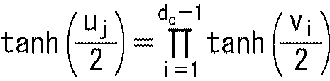


・・・(8) Hc T = 0
... (8)
・・・(9) K = (k + 1) × 360
... (9)
・・・(10) H wj = mod {h i, j + mod ((w-1), P) × q, M)
... (10)
・・・(11) Line replacement: 6s + t + 1 line → 5t + s + 1 line (11)
・・・(12) Column replacement: 6x + y + 61st column → 5y + x + 61th column ... (12)
Claims (13)
- LDPC(Low Density Parity Check)符号の検査行列に基づき、情報ビットを、符号長が16200ビットで符号化率が10/15のLDPC符号に符号化する符号化部を備え、
前記LDPC符号は、情報ビットとパリティビットを含み、
前記検査行列は、前記情報ビットに対応する情報行列部と前記パリティビットに対応するパリティ行列部とを含み、
前記情報行列部は、検査行列初期値テーブルによって表され、
前記検査行列初期値テーブルは、前記情報行列部の1の要素の位置を360列ごとに表すテーブルであって、
352 747 894 1437 1688 1807 1883 2119 2159 3321 3400 3543 3588 3770 3821 4384 4470 4884 5012 5036 5084 5101 5271 5281 5353
505 915 1156 1269 1518 1650 2153 2256 2344 2465 2509 2867 2875 3007 3254 3519 3687 4331 4439 4532 4940 5011 5076 5113 5367
268 346 650 919 1260 4389 4653 4721 4838 5054 5157 5162 5275 5362
220 236 828 1590 1792 3259 3647 4276 4281 4325 4963 4974 5003 5037
381 737 1099 1409 2364 2955 3228 3341 3473 3985 4257 4730 5173 5242
88 771 1640 1737 1803 2408 2575 2974 3167 3464 3780 4501 4901 5047
749 1502 2201 3189
2873 3245 3427
2158 2605 3165
1 3438 3606
10 3019 5221
371 2901 2923
9 3935 4683
1937 3502 3735
507 3128 4994
25 3854 4550
1178 4737 5366
2 223 5304
1146 5175 5197
1816 2313 3649
740 1951 3844
1320 3703 4791
1754 2905 4058
7 917 5277
3048 3954 5396
4804 4824 5105
2812 3895 5226
0 5318 5358
1483 2324 4826
2266 4752 5387
である
データ処理装置。 Based on a parity check matrix of LDPC (Low Density Parity Check) code, it comprises an encoding unit that encodes information bits into an LDPC code with a code length of 16200 bits and a coding rate of 10/15,
The LDPC code includes information bits and parity bits,
The parity check matrix includes an information matrix portion corresponding to the information bits and a parity matrix portion corresponding to the parity bits,
The information matrix part is represented by a parity check matrix initial value table,
The parity check matrix initial value table is a table that represents the position of one element of the information matrix part for every 360 columns,
352 747 894 1437 1688 1807 1883 2119 2159 3321 3400 3543 3588 3770 3821 4384 4470 4884 5012 5036 5084 5101 5271 5281 5353
505 915 1156 1269 1518 1650 2153 2256 2344 2465 2509 2867 2875 3007 3254 3519 3687 4331 4439 4532 4940 5011 5076 5113 5367
268 346 650 919 1260 4389 4653 4721 4838 5054 5157 5162 5275 5362
220 236 828 1590 1792 3259 3647 4276 4281 4325 4963 4974 5003 5037
381 737 1099 1409 2364 2955 3228 3341 3473 3985 4257 4730 5173 5242
88 771 1640 1737 1803 2408 2575 2974 3167 3464 3780 4501 4901 5047
749 1502 2201 3189
2873 3245 3427
2158 2605 3165
1 3438 3606
10 3019 5221
371 2901 2923
9 3935 4683
1937 3502 3735
507 3128 4994
25 3854 4550
1178 4737 5366
2 223 5304
1146 5175 5197
1816 2313 3649
740 1951 3844
1320 3703 4791
1754 2905 4058
7 917 5277
3048 3954 5396
4804 4824 5105
2812 3895 5226
0 5318 5358
1483 2324 4826
2266 4752 5387
Is a data processing device. - 前記検査行列初期テーブルの行をiと表すとともに、前記LDPC符号のパリティ長をMと表すとき、
前記検査行列の2+360×(i-1)列目は、前記検査行列初期値テーブルで1の要素の位置が表される前記検査行列の1+360×(i-1)列目を、q=M/360だけ下方向にサイクリックシフトした列である
請求項1に記載のデータ処理装置。 When the row of the parity check matrix initial table is represented by i and the parity length of the LDPC code is represented by M,
The 2 + 360 × (i-1) column of the parity check matrix is the 1 + 360 × (i-1) column of the parity check matrix in which the position of one element is represented in the parity check matrix initial value table, The data processing apparatus according to claim 1, wherein q is a row that is cyclically shifted downward by M / 360. - 前記検査行列の1+360×(i-1)列については、
前記検査行列初期値テーブルのi行目が、前記検査行列の1+360×(i-1)列目の1の要素の行番号を表し、
前記検査行列の1+360×(i-1)列目以外の列である2+360×(i-1)列目から360×i列目までの各列については、
前記検査行列初期値テーブルのi行目のj列目の数値をhi,jと表すとともに、前記検査行列Hのw列目の、j個目の1の要素の行番号をHw-jと表すとき、
前記検査行列の1+360×(i-1)列目以外の列であるw列目の、1の要素の行番号Hw-jは、式Hw-j=mod{hi,j+mod((w-1),360)×M/360,M)で表される
請求項2に記載のデータ処理装置。 For 1 + 360 × (i-1) columns of the parity check matrix,
The i-th row of the parity check matrix initial value table represents the row number of the 1 element in the 1 + 360 × (i−1) column of the parity check matrix,
For each column from the 2 + 360 × (i-1) column to the 360 × i column other than the 1 + 360 × (i-1) column of the parity check matrix,
The numerical value of the j-th column of the i-th row of the parity check matrix initial value table is represented as h i, j, and the row number of the j-th one element of the w-th column of the parity check matrix H is represented as H wj. When
The row number H wj of the 1 element in the w column, which is a column other than the 1 + 360 × (i−1) column of the parity check matrix, is expressed by the formula H wj = mod {h i, j + mod ((w− The data processing apparatus according to claim 2, represented by 1), 360) × M / 360, M). - 前記LDPC符号の符号ビットのパリティビットのみをインターリーブするパリティインターリーブ部をさらに備える
請求項1に記載のデータ処理装置。 The data processing apparatus according to claim 1, further comprising a parity interleaving unit that interleaves only parity bits of code bits of the LDPC code. - 前記検査行列は、サイクル4が存在しない検査行列である
請求項1に記載のデータ処理装置。 The data processing apparatus according to claim 1, wherein the check matrix is a check matrix in which cycle 4 does not exist. - 前記検査行列は、マルチエッジタイプのデンシティエボリューションによって検出される、BERが落ち始めるEb/N0である性能閾値が所定値以下になるLDPC符号のアンサンブルに属するLDPC符号の検査行列である
請求項1に記載のデータ処理装置。 The parity check matrix is a parity check matrix of an LDPC code belonging to an ensemble of LDPC codes that is detected by multi-edge type density evolution and whose performance threshold value, which is E b / N 0 at which the BER starts to drop, is equal to or less than a predetermined value. The data processing apparatus according to 1. - LDPC(Low Density Parity Check)符号の検査行列に基づき、情報ビットを、符号長が16200ビットで符号化率が10/15のLDPC符号に符号化する符号化ステップを備え、
前記LDPC符号は、情報ビットとパリティビットを含み、
前記検査行列は、前記情報ビットに対応する情報行列部と前記パリティビットに対応するパリティ行列部とを含み、
前記情報行列部は、検査行列初期値テーブルによって表され、
前記検査行列初期値テーブルは、前記情報行列部の1の要素の位置を360列ごとに表すテーブルであって、
352 747 894 1437 1688 1807 1883 2119 2159 3321 3400 3543 3588 3770 3821 4384 4470 4884 5012 5036 5084 5101 5271 5281 5353
505 915 1156 1269 1518 1650 2153 2256 2344 2465 2509 2867 2875 3007 3254 3519 3687 4331 4439 4532 4940 5011 5076 5113 5367
268 346 650 919 1260 4389 4653 4721 4838 5054 5157 5162 5275 5362
220 236 828 1590 1792 3259 3647 4276 4281 4325 4963 4974 5003 5037
381 737 1099 1409 2364 2955 3228 3341 3473 3985 4257 4730 5173 5242
88 771 1640 1737 1803 2408 2575 2974 3167 3464 3780 4501 4901 5047
749 1502 2201 3189
2873 3245 3427
2158 2605 3165
1 3438 3606
10 3019 5221
371 2901 2923
9 3935 4683
1937 3502 3735
507 3128 4994
25 3854 4550
1178 4737 5366
2 223 5304
1146 5175 5197
1816 2313 3649
740 1951 3844
1320 3703 4791
1754 2905 4058
7 917 5277
3048 3954 5396
4804 4824 5105
2812 3895 5226
0 5318 5358
1483 2324 4826
2266 4752 5387
である
データ処理方法。 Based on a check matrix of LDPC (Low Density Parity Check) code, the information bits are provided with an encoding step for encoding an LDPC code with a code length of 16200 bits and an encoding rate of 10/15,
The LDPC code includes information bits and parity bits,
The parity check matrix includes an information matrix portion corresponding to the information bits and a parity matrix portion corresponding to the parity bits,
The information matrix part is represented by a parity check matrix initial value table,
The parity check matrix initial value table is a table that represents the position of one element of the information matrix part for every 360 columns,
352 747 894 1437 1688 1807 1883 2119 2159 3321 3400 3543 3588 3770 3821 4384 4470 4884 5012 5036 5084 5101 5271 5281 5353
505 915 1156 1269 1518 1650 2153 2256 2344 2465 2509 2867 2875 3007 3254 3519 3687 4331 4439 4532 4940 5011 5076 5113 5367
268 346 650 919 1260 4389 4653 4721 4838 5054 5157 5162 5275 5362
220 236 828 1590 1792 3259 3647 4276 4281 4325 4963 4974 5003 5037
381 737 1099 1409 2364 2955 3228 3341 3473 3985 4257 4730 5173 5242
88 771 1640 1737 1803 2408 2575 2974 3167 3464 3780 4501 4901 5047
749 1502 2201 3189
2873 3245 3427
2158 2605 3165
1 3438 3606
10 3019 5221
371 2901 2923
9 3935 4683
1937 3502 3735
507 3128 4994
25 3854 4550
1178 4737 5366
2 223 5304
1146 5175 5197
1816 2313 3649
740 1951 3844
1320 3703 4791
1754 2905 4058
7 917 5277
3048 3954 5396
4804 4824 5105
2812 3895 5226
0 5318 5358
1483 2324 4826
2266 4752 5387
Data processing method. - LDPC(Low Density Parity Check)符号の検査行列に基づき、情報ビットを、符号長が16200ビットで符号化率が10/15のLDPC符号に符号化する符号化部を備え、
前記LDPC符号は、情報ビットとパリティビットを含み、
前記検査行列は、前記情報ビットに対応する情報行列部と前記パリティビットに対応するパリティ行列部とを含み、
前記情報行列部は、検査行列初期値テーブルによって表され、
前記検査行列初期値テーブルは、前記情報行列部の1の要素の位置を360列ごとに表すテーブルであって、
352 747 894 1437 1688 1807 1883 2119 2159 3321 3400 3543 3588 3770 3821 4384 4470 4884 5012 5036 5084 5101 5271 5281 5353
505 915 1156 1269 1518 1650 2153 2256 2344 2465 2509 2867 2875 3007 3254 3519 3687 4331 4439 4532 4940 5011 5076 5113 5367
268 346 650 919 1260 4389 4653 4721 4838 5054 5157 5162 5275 5362
220 236 828 1590 1792 3259 3647 4276 4281 4325 4963 4974 5003 5037
381 737 1099 1409 2364 2955 3228 3341 3473 3985 4257 4730 5173 5242
88 771 1640 1737 1803 2408 2575 2974 3167 3464 3780 4501 4901 5047
749 1502 2201 3189
2873 3245 3427
2158 2605 3165
1 3438 3606
10 3019 5221
371 2901 2923
9 3935 4683
1937 3502 3735
507 3128 4994
25 3854 4550
1178 4737 5366
2 223 5304
1146 5175 5197
1816 2313 3649
740 1951 3844
1320 3703 4791
1754 2905 4058
7 917 5277
3048 3954 5396
4804 4824 5105
2812 3895 5226
0 5318 5358
1483 2324 4826
2266 4752 5387
である
送信装置から送信されてくるデータから得られる前記LDPC符号を復号する復号部を備える
データ処理装置。 Based on a parity check matrix of LDPC (Low Density Parity Check) code, it comprises an encoding unit that encodes information bits into an LDPC code with a code length of 16200 bits and a coding rate of 10/15,
The LDPC code includes information bits and parity bits,
The parity check matrix includes an information matrix portion corresponding to the information bits and a parity matrix portion corresponding to the parity bits,
The information matrix part is represented by a parity check matrix initial value table,
The parity check matrix initial value table is a table that represents the position of one element of the information matrix part for every 360 columns,
352 747 894 1437 1688 1807 1883 2119 2159 3321 3400 3543 3588 3770 3821 4384 4470 4884 5012 5036 5084 5101 5271 5281 5353
505 915 1156 1269 1518 1650 2153 2256 2344 2465 2509 2867 2875 3007 3254 3519 3687 4331 4439 4532 4940 5011 5076 5113 5367
268 346 650 919 1260 4389 4653 4721 4838 5054 5157 5162 5275 5362
220 236 828 1590 1792 3259 3647 4276 4281 4325 4963 4974 5003 5037
381 737 1099 1409 2364 2955 3228 3341 3473 3985 4257 4730 5173 5242
88 771 1640 1737 1803 2408 2575 2974 3167 3464 3780 4501 4901 5047
749 1502 2201 3189
2873 3245 3427
2158 2605 3165
1 3438 3606
10 3019 5221
371 2901 2923
9 3935 4683
1937 3502 3735
507 3128 4994
25 3854 4550
1178 4737 5366
2 223 5304
1146 5175 5197
1816 2313 3649
740 1951 3844
1320 3703 4791
1754 2905 4058
7 917 5277
3048 3954 5396
4804 4824 5105
2812 3895 5226
0 5318 5358
1483 2324 4826
2266 4752 5387
A data processing apparatus comprising: a decoding unit that decodes the LDPC code obtained from data transmitted from a transmission apparatus. - 前記検査行列初期テーブルの行をiと表すとともに、前記LDPC符号のパリティ長をMと表すとき、
前記検査行列の2+360×(i-1)列目は、前記検査行列初期値テーブルで1の要素の位置が表される前記検査行列の1+360×(i-1)列目を、q=M/360だけ下方向にサイクリックシフトした列である
請求項8に記載のデータ処理装置。 When the row of the parity check matrix initial table is represented by i and the parity length of the LDPC code is represented by M,
The 2 + 360 × (i-1) column of the parity check matrix is the 1 + 360 × (i-1) column of the parity check matrix in which the position of one element is represented in the parity check matrix initial value table, The data processing apparatus according to claim 8, wherein q is a row that is cyclically shifted downward by M / 360. - 前記検査行列の1+360×(i-1)列については、
前記検査行列初期値テーブルのi行目が、前記検査行列の1+360×(i-1)列目の1の要素の行番号を表し、
前記検査行列の1+360×(i-1)列目以外の列である2+360×(i-1)列目から360×i列目までの各列については、
前記検査行列初期値テーブルのi行目のj列目の数値をhi,jと表すとともに、前記検査行列Hのw列目の、j個目の1の要素の行番号をHw-jと表すとき、
前記検査行列の1+360×(i-1)列目以外の列であるw列目の、1の要素の行番号Hw-jは、式Hw-j=mod{hi,j+mod((w-1),360)×M/360,M)で表される
請求項9に記載のデータ処理装置。 For 1 + 360 × (i-1) columns of the parity check matrix,
The i-th row of the parity check matrix initial value table represents the row number of the 1 element in the 1 + 360 × (i−1) column of the parity check matrix,
For each column from the 2 + 360 × (i-1) column to the 360 × i column other than the 1 + 360 × (i-1) column of the parity check matrix,
The numerical value of the j-th column of the i-th row of the parity check matrix initial value table is represented as h i, j, and the row number of the j-th one element of the w-th column of the parity check matrix H is represented as H wj. When
The row number H wj of the 1 element in the w column, which is a column other than the 1 + 360 × (i−1) column of the parity check matrix, is expressed by the formula H wj = mod {h i, j + mod ((w− The data processing device according to claim 9, represented by 1), 360) × M / 360, M). - 前記検査行列は、サイクル4が存在しない検査行列である
請求項8に記載のデータ処理装置。 The data processing apparatus according to claim 8, wherein the check matrix is a check matrix in which cycle 4 does not exist. - 前記検査行列は、マルチエッジタイプのデンシティエボリューションによって検出される、BERが落ち始めるEb/N0である性能閾値が所定値以下になるLDPC符号のアンサンブルに属するLDPC符号の検査行列である
請求項8に記載のデータ処理装置。 The parity check matrix is a parity check matrix of an LDPC code belonging to an ensemble of LDPC codes that is detected by multi-edge type density evolution and whose performance threshold value, which is E b / N 0 at which the BER starts to drop, is equal to or less than a predetermined value. 9. A data processing apparatus according to 8. - LDPC(Low Density Parity Check)符号の検査行列に基づき、情報ビットを、符号長が16200ビットで符号化率が10/15のLDPC符号に符号化する符号化部を備え、
前記LDPC符号は、情報ビットとパリティビットを含み、
前記検査行列は、前記情報ビットに対応する情報行列部と前記パリティビットに対応するパリティ行列部とを含み、
前記情報行列部は、検査行列初期値テーブルによって表され、
前記検査行列初期値テーブルは、前記情報行列部の1の要素の位置を360列ごとに表すテーブルであって、
352 747 894 1437 1688 1807 1883 2119 2159 3321 3400 3543 3588 3770 3821 4384 4470 4884 5012 5036 5084 5101 5271 5281 5353
505 915 1156 1269 1518 1650 2153 2256 2344 2465 2509 2867 2875 3007 3254 3519 3687 4331 4439 4532 4940 5011 5076 5113 5367
268 346 650 919 1260 4389 4653 4721 4838 5054 5157 5162 5275 5362
220 236 828 1590 1792 3259 3647 4276 4281 4325 4963 4974 5003 5037
381 737 1099 1409 2364 2955 3228 3341 3473 3985 4257 4730 5173 5242
88 771 1640 1737 1803 2408 2575 2974 3167 3464 3780 4501 4901 5047
749 1502 2201 3189
2873 3245 3427
2158 2605 3165
1 3438 3606
10 3019 5221
371 2901 2923
9 3935 4683
1937 3502 3735
507 3128 4994
25 3854 4550
1178 4737 5366
2 223 5304
1146 5175 5197
1816 2313 3649
740 1951 3844
1320 3703 4791
1754 2905 4058
7 917 5277
3048 3954 5396
4804 4824 5105
2812 3895 5226
0 5318 5358
1483 2324 4826
2266 4752 5387
である
送信装置から送信されてくるデータから得られる前記LDPC符号を復号する復号ステップを備える
データ処理方法。 Based on a parity check matrix of LDPC (Low Density Parity Check) code, it comprises an encoding unit that encodes information bits into an LDPC code with a code length of 16200 bits and a coding rate of 10/15,
The LDPC code includes information bits and parity bits,
The parity check matrix includes an information matrix portion corresponding to the information bits and a parity matrix portion corresponding to the parity bits,
The information matrix part is represented by a parity check matrix initial value table,
The parity check matrix initial value table is a table that represents the position of one element of the information matrix part for every 360 columns,
352 747 894 1437 1688 1807 1883 2119 2159 3321 3400 3543 3588 3770 3821 4384 4470 4884 5012 5036 5084 5101 5271 5281 5353
505 915 1156 1269 1518 1650 2153 2256 2344 2465 2509 2867 2875 3007 3254 3519 3687 4331 4439 4532 4940 5011 5076 5113 5367
268 346 650 919 1260 4389 4653 4721 4838 5054 5157 5162 5275 5362
220 236 828 1590 1792 3259 3647 4276 4281 4325 4963 4974 5003 5037
381 737 1099 1409 2364 2955 3228 3341 3473 3985 4257 4730 5173 5242
88 771 1640 1737 1803 2408 2575 2974 3167 3464 3780 4501 4901 5047
749 1502 2201 3189
2873 3245 3427
2158 2605 3165
1 3438 3606
10 3019 5221
371 2901 2923
9 3935 4683
1937 3502 3735
507 3128 4994
25 3854 4550
1178 4737 5366
2 223 5304
1146 5175 5197
1816 2313 3649
740 1951 3844
1320 3703 4791
1754 2905 4058
7 917 5277
3048 3954 5396
4804 4824 5105
2812 3895 5226
0 5318 5358
1483 2324 4826
2266 4752 5387
A data processing method comprising: a decoding step of decoding the LDPC code obtained from data transmitted from a transmission device.
Priority Applications (10)
| Application Number | Priority Date | Filing Date | Title |
|---|---|---|---|
| CA2923596A CA2923596C (en) | 2013-09-20 | 2014-09-05 | Data processing device and data processing method |
| EP14845759.1A EP3048734B1 (en) | 2013-09-20 | 2014-09-05 | Encoding and decoding of a rate 10/15 ldpc code of length 16200 for dvb |
| CN201480050423.2A CN105531935B (en) | 2013-09-20 | 2014-09-05 | Data processing apparatus and data processing method |
| JP2015537644A JP6364417B2 (en) | 2013-09-20 | 2014-09-05 | Data processing apparatus, data processing method, and recording medium |
| KR1020167003085A KR101752331B1 (en) | 2013-09-20 | 2014-09-05 | Data processing device and data processing method |
| KR1020177017244A KR101929296B1 (en) | 2013-09-20 | 2014-09-05 | Data processing device and data processing method |
| KR1020187035724A KR102113943B1 (en) | 2013-09-20 | 2014-09-05 | Data processing device and data processing method |
| US14/913,870 US10277257B2 (en) | 2013-09-20 | 2014-09-05 | Data processing device and data processing method |
| MX2016003229A MX369485B (en) | 2013-09-20 | 2014-09-05 | Data processing device and data processing method. |
| US16/352,175 US10951241B2 (en) | 2013-09-20 | 2019-03-13 | Data processing device and data processing method |
Applications Claiming Priority (2)
| Application Number | Priority Date | Filing Date | Title |
|---|---|---|---|
| JP2013-196090 | 2013-09-20 | ||
| JP2013196090 | 2013-09-20 |
Related Child Applications (2)
| Application Number | Title | Priority Date | Filing Date |
|---|---|---|---|
| US14/913,870 A-371-Of-International US10277257B2 (en) | 2013-09-20 | 2014-09-05 | Data processing device and data processing method |
| US16/352,175 Continuation US10951241B2 (en) | 2013-09-20 | 2019-03-13 | Data processing device and data processing method |
Publications (1)
| Publication Number | Publication Date |
|---|---|
| WO2015041074A1 true WO2015041074A1 (en) | 2015-03-26 |
Family
ID=52688725
Family Applications (1)
| Application Number | Title | Priority Date | Filing Date |
|---|---|---|---|
| PCT/JP2014/073469 WO2015041074A1 (en) | 2013-09-20 | 2014-09-05 | Data processing device and data processing method |
Country Status (8)
| Country | Link |
|---|---|
| US (2) | US10277257B2 (en) |
| EP (1) | EP3048734B1 (en) |
| JP (1) | JP6364417B2 (en) |
| KR (3) | KR101929296B1 (en) |
| CN (1) | CN105531935B (en) |
| CA (1) | CA2923596C (en) |
| MX (2) | MX369485B (en) |
| WO (1) | WO2015041074A1 (en) |
Cited By (1)
| Publication number | Priority date | Publication date | Assignee | Title |
|---|---|---|---|---|
| WO2018168428A1 (en) * | 2017-03-13 | 2018-09-20 | ソニーセミコンダクタソリューションズ株式会社 | Transmission device and transmission method, reception device and reception method, and program |
Families Citing this family (5)
| Publication number | Priority date | Publication date | Assignee | Title |
|---|---|---|---|---|
| WO2015041074A1 (en) * | 2013-09-20 | 2015-03-26 | ソニー株式会社 | Data processing device and data processing method |
| MX2016000460A (en) * | 2014-05-21 | 2016-08-01 | Sony Corp | Data-processing device and data processing method. |
| CA2948600C (en) | 2014-05-21 | 2022-11-29 | Sony Corporation | Data processing device and method for decreasing the signal-to-noise power ratio per symbol for a selected bit error rate of a digital television broadcasting signal |
| US20160336968A1 (en) * | 2015-05-11 | 2016-11-17 | Comtech Ef Data Corp. | System and method for encoding and decoding using a plurality of constellations within a single fec block |
| KR102389035B1 (en) * | 2017-12-06 | 2022-04-22 | 한국전자통신연구원 | Method for transmitting and receiving compressed data and apparatus using the same |
Citations (4)
| Publication number | Priority date | Publication date | Assignee | Title |
|---|---|---|---|---|
| JP2008263566A (en) * | 2007-03-20 | 2008-10-30 | Nippon Hoso Kyokai <Nhk> | Encoder and decoder, and transmitter and receiver |
| JP4224777B2 (en) | 2003-05-13 | 2009-02-18 | ソニー株式会社 | Decoding method, decoding apparatus, and program |
| JP2013005124A (en) * | 2011-06-15 | 2013-01-07 | Sony Corp | Data processor and data-processing method |
| WO2013024584A1 (en) * | 2011-08-17 | 2013-02-21 | パナソニック株式会社 | Interleaving method and deinterleaving method |
Family Cites Families (21)
| Publication number | Priority date | Publication date | Assignee | Title |
|---|---|---|---|---|
| CN1902828B (en) | 2003-08-08 | 2012-02-29 | 英特尔公司 | Method and apparatus for varying lengths of low density parity check codewords |
| ES2649560T3 (en) * | 2007-11-26 | 2018-01-12 | Saturn Licensing Llc | Method and apparatus for coding and method and apparatus for decoding an LDPC code of 64K and rate 2/3 |
| TWI410055B (en) * | 2007-11-26 | 2013-09-21 | Sony Corp | Data processing device, data processing method and program product for performing data processing method on computer |
| TWI497920B (en) | 2007-11-26 | 2015-08-21 | Sony Corp | Data processing device and data processing method |
| EP2091156B1 (en) | 2008-02-18 | 2013-08-28 | Samsung Electronics Co., Ltd. | Apparatus and method for channel encoding and decoding in a communication system using low-density parity-check codes |
| JP2011176645A (en) | 2010-02-24 | 2011-09-08 | Sony Corp | Data processing apparatus and data processing method |
| JP2011176783A (en) | 2010-02-26 | 2011-09-08 | Sony Corp | Data processing device, and data processing method |
| JP5500379B2 (en) | 2010-09-03 | 2014-05-21 | ソニー株式会社 | Data processing apparatus and data processing method |
| JP5630278B2 (en) * | 2010-12-28 | 2014-11-26 | ソニー株式会社 | Data processing apparatus and data processing method |
| JP2012235269A (en) * | 2011-04-28 | 2012-11-29 | Sony Corp | Data processing device and data processing method |
| KR20150005853A (en) * | 2013-07-05 | 2015-01-15 | 삼성전자주식회사 | transmitter apparatus and signal processing method thereof |
| WO2015041074A1 (en) * | 2013-09-20 | 2015-03-26 | ソニー株式会社 | Data processing device and data processing method |
| CA2924783A1 (en) * | 2013-09-26 | 2015-04-02 | Sony Corporation | Data processing device and data processing method |
| US9735809B2 (en) * | 2013-09-26 | 2017-08-15 | Samsung Electronics Co., Ltd. | Transmitting apparatus and signal processing method thereof |
| US20160233890A1 (en) * | 2013-09-26 | 2016-08-11 | Sony Corporation | Data processing device and data processing method |
| MX2016003576A (en) * | 2013-09-26 | 2016-06-02 | Sony Corp | Data processing device and data processing method. |
| US9577679B2 (en) * | 2013-10-04 | 2017-02-21 | Samsung Electronics Co., Ltd. | Transmitting apparatus and signal processing method thereof |
| US9871621B2 (en) * | 2013-10-30 | 2018-01-16 | Samsung Electronics Co., Ltd. | Transmitting apparatus and signal processing method thereof |
| CA2948600C (en) * | 2014-05-21 | 2022-11-29 | Sony Corporation | Data processing device and method for decreasing the signal-to-noise power ratio per symbol for a selected bit error rate of a digital television broadcasting signal |
| CA2918520C (en) * | 2014-05-21 | 2023-10-10 | Sony Corporation | Data processing device and data processing method |
| MX2016000460A (en) * | 2014-05-21 | 2016-08-01 | Sony Corp | Data-processing device and data processing method. |
-
2014
- 2014-09-05 WO PCT/JP2014/073469 patent/WO2015041074A1/en active Application Filing
- 2014-09-05 MX MX2016003229A patent/MX369485B/en active IP Right Grant
- 2014-09-05 EP EP14845759.1A patent/EP3048734B1/en active Active
- 2014-09-05 KR KR1020177017244A patent/KR101929296B1/en active IP Right Grant
- 2014-09-05 KR KR1020187035724A patent/KR102113943B1/en active IP Right Grant
- 2014-09-05 CN CN201480050423.2A patent/CN105531935B/en active Active
- 2014-09-05 CA CA2923596A patent/CA2923596C/en active Active
- 2014-09-05 KR KR1020167003085A patent/KR101752331B1/en active IP Right Grant
- 2014-09-05 US US14/913,870 patent/US10277257B2/en active Active
- 2014-09-05 JP JP2015537644A patent/JP6364417B2/en active Active
-
2016
- 2016-03-11 MX MX2019013223A patent/MX2019013223A/en unknown
-
2019
- 2019-03-13 US US16/352,175 patent/US10951241B2/en active Active
Patent Citations (4)
| Publication number | Priority date | Publication date | Assignee | Title |
|---|---|---|---|---|
| JP4224777B2 (en) | 2003-05-13 | 2009-02-18 | ソニー株式会社 | Decoding method, decoding apparatus, and program |
| JP2008263566A (en) * | 2007-03-20 | 2008-10-30 | Nippon Hoso Kyokai <Nhk> | Encoder and decoder, and transmitter and receiver |
| JP2013005124A (en) * | 2011-06-15 | 2013-01-07 | Sony Corp | Data processor and data-processing method |
| WO2013024584A1 (en) * | 2011-08-17 | 2013-02-21 | パナソニック株式会社 | Interleaving method and deinterleaving method |
Non-Patent Citations (5)
| Title |
|---|
| "Digital Video Broadcasting(DVB); Next Generation broadcasting system to Handheld, physical layer specification(DVB-NGH", DVB DOCUMENT A160, November 2012 (2012-11-01), pages 65,66,220 - 225,247, 248,261,262, XP055055777 * |
| "Digital Video Broadcasting(DVB); Second generation framing structure, channel coding and modulation systems for Broadcasting", INTERACTIVE SERVICES, NEWS GATHERING AND OTHER BROADBAND SATELLITE APPLICATIONS, PART II: S2- EXTENSIONS(DVB-S2X) - (OPTIONAL), DVB DOCUMENT A83-2, March 2014 (2014-03-01), pages 45 - 83, XP055290304 * |
| DVB-S.2 : ETSI EN 302 307 V1.2.1, August 2009 (2009-08-01) |
| H. JIN; A. KHANDEKAR; R. J. MCELIECE: "Irregular Repeat-Accumulate Codes", PROCEEDINGS OF 2ND INTERNATIONAL SYMPOSIUM ON TURBO CODES AND RELATED TOPICS, September 2000 (2000-09-01), pages 1 - 8, XP002325752 |
| S. Y. CHUNG; G. D. FORNEY; T. J. RICHARDSON; R. URBANKE: "On the Design of Low-Density Parity-Check Codes within 0.0045 dB of the Shannon Limit", IEEE COMMUNICATIONS LEGGERS, vol. 5, no. 2, February 2001 (2001-02-01), XP011083973, DOI: doi:10.1109/4234.905935 |
Cited By (6)
| Publication number | Priority date | Publication date | Assignee | Title |
|---|---|---|---|---|
| WO2018168428A1 (en) * | 2017-03-13 | 2018-09-20 | ソニーセミコンダクタソリューションズ株式会社 | Transmission device and transmission method, reception device and reception method, and program |
| CN110192350A (en) * | 2017-03-13 | 2019-08-30 | 索尼半导体解决方案公司 | Sending device and sending method, receiving device and method of reseptance and program |
| JP2019193306A (en) * | 2017-03-13 | 2019-10-31 | ソニーセミコンダクタソリューションズ株式会社 | Transmitter and transmission method, receiver and reception method, and program |
| US11012091B2 (en) | 2017-03-13 | 2021-05-18 | Sony Corporation | Transmitting apparatus and transmission method, receiving apparatus and reception method, and program |
| JP7077276B2 (en) | 2017-03-13 | 2022-05-30 | ソニーセミコンダクタソリューションズ株式会社 | Transmitter and transmit method, receiver and receive method, and program |
| CN110192350B (en) * | 2017-03-13 | 2023-08-29 | 索尼半导体解决方案公司 | Transmitting apparatus and transmitting method, receiving apparatus and receiving method, and program |
Also Published As
| Publication number | Publication date |
|---|---|
| US10277257B2 (en) | 2019-04-30 |
| US10951241B2 (en) | 2021-03-16 |
| KR20180133948A (en) | 2018-12-17 |
| CN105531935B (en) | 2020-03-31 |
| US20160204806A1 (en) | 2016-07-14 |
| KR102113943B1 (en) | 2020-05-21 |
| MX369485B (en) | 2019-11-11 |
| KR101752331B1 (en) | 2017-06-29 |
| MX2019013223A (en) | 2020-01-15 |
| KR101929296B1 (en) | 2018-12-17 |
| JP6364417B2 (en) | 2018-07-25 |
| CA2923596C (en) | 2021-03-30 |
| CN105531935A (en) | 2016-04-27 |
| EP3048734A4 (en) | 2017-05-10 |
| CA2923596A1 (en) | 2015-03-26 |
| EP3048734B1 (en) | 2019-01-02 |
| JPWO2015041074A1 (en) | 2017-03-02 |
| KR20160060028A (en) | 2016-05-27 |
| MX2016003229A (en) | 2016-06-07 |
| KR20170077269A (en) | 2017-07-05 |
| EP3048734A1 (en) | 2016-07-27 |
| US20190215020A1 (en) | 2019-07-11 |
Similar Documents
| Publication | Publication Date | Title |
|---|---|---|
| JP6517313B2 (en) | Digital broadcast receiving apparatus and digital broadcast receiving method | |
| JP5630278B2 (en) | Data processing apparatus and data processing method | |
| JP5601182B2 (en) | Data processing apparatus and data processing method | |
| JP5664919B2 (en) | Data processing apparatus and data processing method | |
| WO2015178216A1 (en) | Data processing device and data processing method | |
| WO2012165161A1 (en) | Data processing device and data processing method | |
| WO2014123018A1 (en) | Data processing device and data processing method | |
| WO2014123017A1 (en) | Data processing device and data processing method | |
| WO2015178213A1 (en) | Data-processing device and data processing method | |
| WO2014178298A1 (en) | Data processing device and data processing method | |
| JP6364416B2 (en) | Data processing apparatus, data processing method, and recording medium | |
| WO2014123014A1 (en) | Data processing device and data processing method | |
| WO2014123015A1 (en) | Data processing device and data processing method | |
| WO2015178212A1 (en) | Data-processing device and data processing method | |
| JP6364417B2 (en) | Data processing apparatus, data processing method, and recording medium | |
| JP6229900B2 (en) | Data processing apparatus and data processing method | |
| JP6229902B2 (en) | Data processing apparatus and data processing method | |
| JP6229899B2 (en) | Data processing apparatus and data processing method | |
| WO2015178211A1 (en) | Data-processing device and data processing method | |
| WO2015141489A1 (en) | Data processing device and data processing method | |
| WO2014123016A1 (en) | Data processing device and data processing method | |
| WO2015178210A1 (en) | Data-processing device and data processing method | |
| WO2015041072A1 (en) | Data processing device and data processing method | |
| WO2015141488A1 (en) | Data processing device and data processing method | |
| WO2014178299A1 (en) | Data processing device and data processing method |
Legal Events
| Date | Code | Title | Description |
|---|---|---|---|
| WWE | Wipo information: entry into national phase |
Ref document number: 201480050423.2 Country of ref document: CN |
|
| 121 | Ep: the epo has been informed by wipo that ep was designated in this application |
Ref document number: 14845759 Country of ref document: EP Kind code of ref document: A1 |
|
| ENP | Entry into the national phase |
Ref document number: 20167003085 Country of ref document: KR Kind code of ref document: A |
|
| ENP | Entry into the national phase |
Ref document number: 2015537644 Country of ref document: JP Kind code of ref document: A |
|
| WWE | Wipo information: entry into national phase |
Ref document number: 14913870 Country of ref document: US |
|
| ENP | Entry into the national phase |
Ref document number: 2923596 Country of ref document: CA |
|
| REEP | Request for entry into the european phase |
Ref document number: 2014845759 Country of ref document: EP |
|
| WWE | Wipo information: entry into national phase |
Ref document number: MX/A/2016/003229 Country of ref document: MX Ref document number: 2014845759 Country of ref document: EP |
|
| NENP | Non-entry into the national phase |
Ref country code: DE |