WO2015177149A1 - Electrical apparatus for the generation, transmission, distribution and/or usage of electrical energy and method for recovering a substance from an insulation medium of such an apparatus - Google Patents

Electrical apparatus for the generation, transmission, distribution and/or usage of electrical energy and method for recovering a substance from an insulation medium of such an apparatus Download PDF

Info

Publication number
WO2015177149A1
WO2015177149A1 PCT/EP2015/060994 EP2015060994W WO2015177149A1 WO 2015177149 A1 WO2015177149 A1 WO 2015177149A1 EP 2015060994 W EP2015060994 W EP 2015060994W WO 2015177149 A1 WO2015177149 A1 WO 2015177149A1
Authority
WO
WIPO (PCT)
Prior art keywords
organofluorine compound
electrical apparatus
gas mixture
compound
initial gas
Prior art date
Legal status (The legal status is an assumption and is not a legal conclusion. Google has not performed a legal analysis and makes no representation as to the accuracy of the status listed.)
Ceased
Application number
PCT/EP2015/060994
Other languages
French (fr)
Inventor
Carles JOHNSSON
Daniel Boesch
Javier MANTILLA FLOREZ
Oliver Cossalter
Stephan Grob
Current Assignee (The listed assignees may be inaccurate. Google has not performed a legal analysis and makes no representation or warranty as to the accuracy of the list.)
ABB Technology AG
Original Assignee
ABB Technology AG
Priority date (The priority date is an assumption and is not a legal conclusion. Google has not performed a legal analysis and makes no representation as to the accuracy of the date listed.)
Filing date
Publication date
Family has litigation
First worldwide family litigation filed litigation Critical https://patents.darts-ip.com/?family=50842238&utm_source=google_patent&utm_medium=platform_link&utm_campaign=public_patent_search&patent=WO2015177149(A1) "Global patent litigation dataset” by Darts-ip is licensed under a Creative Commons Attribution 4.0 International License.
Application filed by ABB Technology AG filed Critical ABB Technology AG
Priority to MX2016014972A priority Critical patent/MX2016014972A/en
Priority to CA2949581A priority patent/CA2949581A1/en
Priority to EP15723932.8A priority patent/EP3146531B2/en
Priority to CN201580025971.4A priority patent/CN106537705B/en
Priority to AU2015261942A priority patent/AU2015261942A1/en
Publication of WO2015177149A1 publication Critical patent/WO2015177149A1/en
Anticipated expiration legal-status Critical
Priority to US15/356,991 priority patent/US10256008B2/en
Ceased legal-status Critical Current

Links

Classifications

    • HELECTRICITY
    • H01ELECTRIC ELEMENTS
    • H01BCABLES; CONDUCTORS; INSULATORS; SELECTION OF MATERIALS FOR THEIR CONDUCTIVE, INSULATING OR DIELECTRIC PROPERTIES
    • H01B3/00Insulators or insulating bodies characterised by the insulating materials; Selection of materials for their insulating or dielectric properties
    • H01B3/18Insulators or insulating bodies characterised by the insulating materials; Selection of materials for their insulating or dielectric properties mainly consisting of organic substances
    • H01B3/20Insulators or insulating bodies characterised by the insulating materials; Selection of materials for their insulating or dielectric properties mainly consisting of organic substances liquids, e.g. oils
    • H01B3/24Insulators or insulating bodies characterised by the insulating materials; Selection of materials for their insulating or dielectric properties mainly consisting of organic substances liquids, e.g. oils containing halogen in the molecules, e.g. halogenated oils
    • HELECTRICITY
    • H02GENERATION; CONVERSION OR DISTRIBUTION OF ELECTRIC POWER
    • H02BBOARDS, SUBSTATIONS OR SWITCHING ARRANGEMENTS FOR THE SUPPLY OR DISTRIBUTION OF ELECTRIC POWER
    • H02B13/00Arrangement of switchgear in which switches are enclosed in, or structurally associated with, a casing, e.g. cubicle
    • H02B13/02Arrangement of switchgear in which switches are enclosed in, or structurally associated with, a casing, e.g. cubicle with metal casing
    • H02B13/035Gas-insulated switchgear
    • H02B13/055Features relating to the gas
    • BPERFORMING OPERATIONS; TRANSPORTING
    • B01PHYSICAL OR CHEMICAL PROCESSES OR APPARATUS IN GENERAL
    • B01DSEPARATION
    • B01D5/00Condensation of vapours; Recovering volatile solvents by condensation
    • B01D5/0057Condensation of vapours; Recovering volatile solvents by condensation in combination with other processes
    • B01D5/0069Condensation of vapours; Recovering volatile solvents by condensation in combination with other processes with degasification or deaeration
    • BPERFORMING OPERATIONS; TRANSPORTING
    • B01PHYSICAL OR CHEMICAL PROCESSES OR APPARATUS IN GENERAL
    • B01DSEPARATION
    • B01D53/00Separation of gases or vapours; Recovering vapours of volatile solvents from gases; Chemical or biological purification of waste gases, e.g. engine exhaust gases, smoke, fumes, flue gases, aerosols
    • B01D53/002Separation of gases or vapours; Recovering vapours of volatile solvents from gases; Chemical or biological purification of waste gases, e.g. engine exhaust gases, smoke, fumes, flue gases, aerosols by condensation
    • BPERFORMING OPERATIONS; TRANSPORTING
    • B01PHYSICAL OR CHEMICAL PROCESSES OR APPARATUS IN GENERAL
    • B01DSEPARATION
    • B01D7/00Sublimation
    • B01D7/02Crystallisation directly from the vapour phase
    • HELECTRICITY
    • H01ELECTRIC ELEMENTS
    • H01BCABLES; CONDUCTORS; INSULATORS; SELECTION OF MATERIALS FOR THEIR CONDUCTIVE, INSULATING OR DIELECTRIC PROPERTIES
    • H01B3/00Insulators or insulating bodies characterised by the insulating materials; Selection of materials for their insulating or dielectric properties
    • H01B3/18Insulators or insulating bodies characterised by the insulating materials; Selection of materials for their insulating or dielectric properties mainly consisting of organic substances
    • H01B3/56Insulators or insulating bodies characterised by the insulating materials; Selection of materials for their insulating or dielectric properties mainly consisting of organic substances gases
    • HELECTRICITY
    • H01ELECTRIC ELEMENTS
    • H01HELECTRIC SWITCHES; RELAYS; SELECTORS; EMERGENCY PROTECTIVE DEVICES
    • H01H33/00High-tension or heavy-current switches with arc-extinguishing or arc-preventing means
    • H01H33/02Details
    • H01H33/53Cases; Reservoirs, tanks, piping or valves, for arc-extinguishing fluid; Accessories therefor, e.g. safety arrangements, pressure relief devices
    • H01H33/56Gas reservoirs
    • HELECTRICITY
    • H01ELECTRIC ELEMENTS
    • H01HELECTRIC SWITCHES; RELAYS; SELECTORS; EMERGENCY PROTECTIVE DEVICES
    • H01H33/00High-tension or heavy-current switches with arc-extinguishing or arc-preventing means
    • H01H33/60Switches wherein the means for extinguishing or preventing the arc do not include separate means for obtaining or increasing flow of arc-extinguishing fluid
    • H01H33/64Switches wherein the means for extinguishing or preventing the arc do not include separate means for obtaining or increasing flow of arc-extinguishing fluid wherein the break is in gas
    • BPERFORMING OPERATIONS; TRANSPORTING
    • B01PHYSICAL OR CHEMICAL PROCESSES OR APPARATUS IN GENERAL
    • B01DSEPARATION
    • B01D2257/00Components to be removed
    • B01D2257/20Halogens or halogen compounds
    • B01D2257/206Organic halogen compounds
    • B01D2257/2066Fluorine
    • BPERFORMING OPERATIONS; TRANSPORTING
    • B01PHYSICAL OR CHEMICAL PROCESSES OR APPARATUS IN GENERAL
    • B01DSEPARATION
    • B01D2258/00Sources of waste gases
    • B01D2258/02Other waste gases
    • BPERFORMING OPERATIONS; TRANSPORTING
    • B01PHYSICAL OR CHEMICAL PROCESSES OR APPARATUS IN GENERAL
    • B01DSEPARATION
    • B01D7/00Sublimation
    • HELECTRICITY
    • H01ELECTRIC ELEMENTS
    • H01HELECTRIC SWITCHES; RELAYS; SELECTORS; EMERGENCY PROTECTIVE DEVICES
    • H01H33/00High-tension or heavy-current switches with arc-extinguishing or arc-preventing means
    • H01H33/02Details
    • H01H33/53Cases; Reservoirs, tanks, piping or valves, for arc-extinguishing fluid; Accessories therefor, e.g. safety arrangements, pressure relief devices
    • H01H33/56Gas reservoirs
    • H01H2033/566Avoiding the use of SF6

Definitions

  • the present invention relates to an electrical apparatus for the generation, transmission, distribution and/or usage of electrical energy as well as to a method for recovering a substance from an insulation medium of such an apparatus.
  • Dielectric insulation media in liquid or gaseous state are conventionally applied for the insulation of an electrical component in a wide variety of apparatuses, such as for example switchgears, gas-insulated substations (GIS) , gas- insulated lines (GIL), or transformers.
  • GIS gas-insulated substations
  • GIL gas- insulated lines
  • the electrical component is arranged in a gas- tight housing, the interior of which defines an insulating space, said insulation space comprising an insulation gas and separating and electrically insulating the housing from the electrical component.
  • the insulating gas further functions as an arc extinction gas .
  • WO-A- 2010/142346 discloses a dielectric insulation medium comprising a fluoroketone having from 4 to 12 carbon atoms.
  • a dielectric insulation medium of particular relevance is further disclosed in WO 2012/080246, relating to a medium comprising a dielectric insulation gas, which comprises a fluoroketone containing exactly 5 carbon atoms in a mixture with a dielectric insulation gas component different from
  • WO-A-2012/080222 discloses a dielectric insulation medium comprising a hydrofluoro- monoether .
  • Both groups of compounds have been shown to have high insulation capabilities, in particular a high dielectric strength, as well as high arc extinction capabilities. At the same time, they have a very low Global Warming Potential (GWP) and very low toxicity. The combination of these characteristics renders these organofluorine compounds high- ly suitable as a substitute for SF 6 (sulphur hexafluoride ) , which is commonly used as a dielectric insulation medium, but which is known to have a high GWP.
  • SF 6 sulfur hexafluoride
  • organofluorine compounds can be subject to decomposition. Different to SF 6 the decomposed organo- fluorine compounds usually do not recombine .
  • WO 2014/053661 suggests an apparatus for the generation, the distribution and/or the usage of electrical energy comprising a molecular sieve arranged such as to come into contact with the insulation gas, the molecular sieve having an average pore size greater than the molecular size of at least one decomposition product of the organofluorine compound generated during operation of the apparatus.
  • the problem to be solved by the present invention is, thus, to provide an electrical apparatus using an insulation medium comprising an organofluorine compound, said apparatus allowing to minimize the amount of organofluorine compound to be used and at the same time, the present invention shall allow for a safe overall operability, and in particular for a safe evacuation operation.
  • the present invention relates to an electrical apparatus for the generation, transmission, distribution and/or usage of electrical energy
  • the electrical apparatus comprising a housing enclosing an electrical apparatus interior space, at least a portion of the electrical apparatus interior space comprising at least one insulation space, in which an electrical component is arranged and which contains an insulation medium surrounding the electrical component.
  • the insulation medium comprises an organofluorine compound and at least one further component in gaseous phase.
  • the apparatus further comprises a gas flow generating device designed to generate a flow of an initial
  • the separator is or comprises a liquefaction device adapted for or having means for liquefying and/or a solidification device adapted for or having means for solidifying the organofluorine compound.
  • the present invention allows the organofluorine compound to be recycled into the insulation space, which is not only highly advantageous from an economic point of view. Since disposal of the organofluorine compound can be omitted, the present invention also brings an ecological benefit.
  • recovery is according to the invention obtained by liquefaction and/or solidification of the organofluorine compound. Since separation by liquefaction is in most cases simpler to perform than by solidification, use of a liquefaction device is the preferred embodiment.
  • the terms “liquefying” or “liquefaction” as used in the context of the present invention are to be interpreted as a phase transition of the respective sub ⁇ stance, particularly the gaseous organofluorine compound, to the liquid phase.
  • solidifying or “solidification” as used in the context of the present invention are to be interpreted as a phase transition of the
  • phase separation is achieved by the liquefaction and/or solidification, which in most cases allows the substances of the respective phases to be separated from each other mechanically.
  • the separator used according to the present invention generally functions in manner to allow the liquid or solid organofluorine compound obtained to flow or fall down, thus allowing consolidating and collecting the liquid or solid organo- fluorine compound.
  • the separator is thus in any respect different from a filter through which the insulation gas is pumped and which requires that the organofluorine compound remains in gaseous phase .
  • the separator can be or can comprise for example a snow-gun, a cyclone separator, a centrifuge drum or a knitmesh (or wire-mesh) separator.
  • the separator comprises a liquefaction device or solidification device.
  • the separator comprises a liquefaction device for generating droplets, whereas if a snow-gun is used, the separator comprises a solidification device for generating solid crystaline particles.
  • the present invention further allows evacuation of the insulation space by means of a pump without facing the problem of liquefaction in the pressurization zone of the pump.
  • replacement of the insulation medium can be carried out in a very safe manner.
  • initial gas mixture as used in the context of the present invention is to be interpreted broadly and encompasses any possible gas mixture containing the organofluorine compound and at least one further component of the insulation medium.
  • the initial gas mixture is at least essentially identical to the insulation medium .
  • insulation medium relates to the insulation medium to be replaced, i.e. the insulation medium (or its composition) present in the insulation space at the time directly prior to refurbishment.
  • This insulation medium has in comparison to the insulation medium used for filling the insulation space a lower amount of organofluorine compound and a higher amount of decomposition products.
  • the composition of the insulation medium can change over time, specifically due to the mentioned decomposition phenomena. For example, partial decomposition of the organofluorine compound can occur during a switching operation of a switching component.
  • the initial gas mixture comprises apart from the organofluorine compound a background gas and at least one decomposition product.
  • the term "initial gas mixture" can also relate to the insulation medium used for filling the insulation space, i.e. the fresh mixture, provided that it contains apart from the organofluorine compound a further component, typically a background gas.
  • the fresh mixture is typically devoid of any decomposition products.
  • the liquefaction device is specifically adapted for liquefying and/or the solidifica ⁇ tion device is specifically adapted for solidifying the organofluorine compound only.
  • the gas mixture passes in the liquefaction and/or solidification device several cooling and/or pres surization steps, each one for removing at least one further component of the gas mixture. In this manner, e.g. decomposition products with relative high dew points can separately be removed from the gas mixture and, in the following, can be conveyed to separate processing and/or disposal steps.
  • the liquefaction device and/or the solidification device is or comprises a cooler for cooling the initial gas mixture down to a temperature below the dew point of the organofluorine compound.
  • the liquefaction device and/or the solidification device can be or can comprise a compressor for liquefying the organofluorine compound by a pressure increase.
  • the outlet opening opens into a primary gas channel which fluidly connects the insulation space with the substance recovery device.
  • the substance recovery device can be arranged directly adjacent to the
  • the substance recovery device further comprises an organoflourine compound collecting device for collecting the organofluorine compound separated by the separator.
  • the substance recovery device comprises at least one organofluorine compound reservoir tank for storing the organofluorine compound separated by the separator.
  • the organofluorine compound is collected, e.g. by means of a vessel into which the liquid organofluorine compound falls or flows, and is ultimately directed to the organofluorine compound reservoir tank in which the organofluorine compound is held under storage conditions. From there, it can be reintroduced into the insulation space when refilling is necessary .
  • the apparatus further comprises a filter arranged between the outlet opening and the substance recovery device and designed such to remove solid or liquid impurities from the flow of the initial mixture.
  • This filter can be attributed to the primary gas channel, e.g. by arranging it in the primary channel, thus forcing the whole amount of the initial gas mixture to pass the filter.
  • a by-pass channel to the primary channel can be provided with the filter being arranged in the by-pass channel, thus only forcing a part of the initial gas mixture to pass the filter.
  • the apparatus further comprises an organofluorine compound recycling channel leading from the substance recovery device to an organofluorine compound inlet opening arranged in the housing and designed such to reintroduce the organofluorine compound into the insulation space.
  • the organofluorine compound recycling channel leads from the organofluorine compound reservoir tank to the organofluorine compound inlet opening.
  • an organofluorine compound treatment device upstream of the organofluorine compound inlet opening an organofluorine compound treatment device can be arranged, in particular for removing impurities from the organofluorine compound to be reintroduced into the insulation space. This organofluorine compound treatment device can be attributed to the organofluorine compound recycling channel.
  • the gas stream generating device is a pump, more particularly a suction pump arranged downstream of the substance recovery device.
  • the suction pump can further function as a compressor for compressing the at least one remaining component of the initial gas mixture, as discussed in more detail below.
  • the pump is designed such to purge the insulation space, thereby forcing the initial gas mixture out of the insulation space.
  • This pump can be identical to the suction pump mentioned above.
  • both the pump inlet as well as the pump outlet are connected to the insulation space, such that a flow of gas from the insulation space to the pump is generated on the suction
  • At least one secondary gas channel branches off from the separator of the substance recovery device, the secondary gas channel being adapted for guiding the at least one remaining component of the initial gas mixture without the organofluorine compound. It is thereby particularly preferred that the secondary gas channel leads to a secondary reservoir tank for storing the at least one remaining component of the initial gas mixture. Forcing the gas through the secondary gas channel can be achieved by means of a pump, in particular by means of the suction pump described above.
  • the pump further functions as a compressor, thus allowing compressing of the gas until liquefaction of at least some of the remaining components, if desired.
  • the secondary gas channel and optionally the secondary reservoir tank, is fluidly connected to a gas inlet opening arranged in the housing.
  • a gas inlet opening arranged in the housing.
  • This gas inlet opening can either be the primary gas inlet opening mentioned above.
  • a gas component mixing unit is arranged upstream of the primary gas inlet opening for mixing the (recovered) organofluorine compound and the (recovered) remaining compound and, optionally further supplementing the mixture, to obtain the desired gas composition to be introduced into the insulation space.
  • the gas inlet opening can be a separate, secondary inlet opening for reintroducing the at
  • a secondary treatment device is arranged, in particular for purifying the at least one remaining component of the initial gas mixture.
  • the organofluorine compound is selected from the group consisting of: fluoroethers , in particular hydrofluoromonoethers , fluoro- ketones, fluoroolefins, in particular hydrofluoroolefins , and mixtures thereof, since these classes of compounds have been found to have very high insulation capabilities, in particular a high dielectric strength (or breakdown field strength) and at the same time a low GWP and low toxicity.
  • the invention encompasses both embodiments in which the respective insulation medium comprises either one of a fluoroether, in particular a hydrofluoromonoether, a fluoroketone and a fluoroolefin, in particular a hydrofluoroolefin, as well as embodiments in which it comprises a mixture of at least two of these compounds.
  • the insulation space comprises a background gas, in particular selected from the group consisting of: air, an air component, nitrogen, oxygen, carbon dioxide, a nitrogen oxide and mixtures thereof.
  • a background gas in particular selected from the group consisting of: air, an air component, nitrogen, oxygen, carbon dioxide, a nitrogen oxide and mixtures thereof.
  • at least one of the remaining components of the initial gas mixture i.e. the initial gas mixture without the organo- fluorine compound, is preferably selected from the group consisting of: air, an air component, nitrogen, oxygen, carbon dioxide, a nitrogen oxide and mixtures thereof.
  • fluoroether as used in the context of the present invention encompasses both perfluoroethers , i.e. fully fluorinated ethers, and hydrofluoroethers , i.e. ethers that
  • fluoroether further encompasses saturated compounds as well as unsaturated compounds, i.e. compounds including double and/or triple bonds between carbon atoms.
  • the at least partially fluorinated alkyl chains attached to the oxygen atom of the fluoroether can, independently of each other, be linear or branched.
  • fluoroether further encompasses both non-cyclic and cyclic ethers.
  • the two alkyl chains attached to the oxygen atom can optionally form a ring.
  • the term encompasses fluorooxiranes .
  • the organofluorine compound according to the present invention is a perfluorooxirane or a hydrofluoro- oxirane, more specifically a perfluorooxirane or hydro- fluorooxirane comprising from three to fifteen carbon atoms.
  • the respective insulation medium comprises a hydrofluoromonoether containing at least three carbon atoms.
  • these hydro- fluoromonoethers are chemically and thermally stable up to temperatures above 140°C. They are further non-toxic or have a low toxicity level. In addition, they are non-corrosive and non-explosive.
  • hydrofluoromonoether refers to a compound having one and only one ether group, said ether group linking two alkyl groups, which can be, independently from each other, linear or branched, and which can optionally form a ring.
  • the compound is thus in clear contrast to the compounds disclosed in e.g. US-B-7128133, which relates to the use of compounds containing two ether groups, i.e. hydrofluorodiethers , in heat-transfer fluids.
  • hydrofluoromonoether as used herein is further to be understood such that the monoether is partially hydrogenated and partially fluorinated. It is further to be
  • hydrofluoromonoethers containing at least three carbon atoms have been found to have a relatively high dielectric strength.
  • the ratio of the dielectric strength of the hydrofluoromonoethers according to the present invention to the dielectric strength of SF 6 is greater than about 0.4.
  • the GWP of the hydrofluoromonoethers is low.
  • the GWP is less than 1' 000 over 100 years, more specifically less than 700 over 100 years.
  • the hydrofluoromonoethers mentioned herein have a relatively low atmospheric lifetime and in addition are devoid of halogen atoms that play a role in the ozone destruction catalytic cycle, namely CI, Br or I. Their Ozone Depletion Potential (ODP) is zero, which is very favourable from an environ- mental perspective.
  • hydrofluoromonoether containing at least three carbon atoms and thus having a relatively high boiling point of more than -20°C is based on the finding that a higher boiling point of the hydrofluoromonoether generally goes along with a higher dielectric strength.
  • the hydrofluoromonoether contains exactly three or four or five or six carbon atoms, in particular exactly three or four carbon atoms, most preferably exactly three carbon atoms. More particularly, the hydrofluoromonoether is thus at least one compound selected from the group consisting of the compounds defined
  • the ratio of the number of fluorine atoms to the total number of fluorine and hydrogen atoms, here briefly called "F-rate", of the hydrofluoromonoether is at least 5:8. It has been found that compounds falling within this definition are generally non-flammable and thus result in an insulation medium complying with highest safety requirements. Thus, safety requirements of the electrical insulator and the method of its production can readily be fulfilled by using a corresponding hydrofluoromonoether .
  • the ratio of the number of fluorine atoms to the number of carbon atoms ranges from 1.5:1 to 2:1.
  • Such compounds generally have a GWP of less than 1' 000 over 100 years and are thus very environment-friendly. It is particularly preferred that the hydrofluoromonoether has a GWP of less than 700 over 100 years.
  • exactly one of c and f in the general structure (0) is 0.
  • the corresponding grouping of fluorines on one side of the ether linkage, with the other side remaining unsubstituted, is called "segregation". Segregation has been found to reduce the boiling point compared to unsegregated compounds of the same chain length.
  • the hydrofluoromonoether is selected from the group consisting of pentafluoro-ethyl-methyl ether (CH 3 - 0-CF 2 CF 3 ) and 2, 2, 2-trifluoroethyl-trifluoromethyl ether (CF 3 -0-CH 2 CF 3 ) .
  • Pentafluoro-ethyl-methyl ether has a boiling point of +5.25°C and a GWP of 697 over 100 years, the F-rate being 0.625, while 2 , 2 , 2-trifluoroethyl-trifluoromethyl ether has a boiling point of +11°C and a GWP of 487 over 100 years, the F-rate being 0.75. They both have an ODP of 0 and are thus environmentally fully acceptable.
  • pentafluoro-ethyl-methyl ether has been found to be thermally stable at a temperature of 175°C for 30 days and therefore to be fully suitable for the operational conditions given in the apparatus.
  • hydrofluoromonoethers and in particular pentafluoro- ethyl-methyl ether as well as 2, 2, 2-trifluoroethyl- trifluoromethyl ether, have a lethal concentration LC 50 of higher than 10' 000 ppm, rendering them suitable also from a toxicological point of view.
  • hydrofluoromonoethers mentioned have a higher dielectric strength than air.
  • pentafluoro-ethyl-methyl ether at 1 bar has a dielectric strength about 2.4 times higher than that of air at 1 bar.
  • the hydrofluoromonoethers mentioned are normally in the gaseous state at operational conditions.
  • a dielectric insulation medium in which every component is in the gaseous state at operational conditions of the apparatus can be achieved, which is advantageous.
  • the respective insulation medium comprises a fluoroketone containing from four to twelve carbon atoms .
  • fluoroketone as used in this application shall be interpreted broadly and shall encompass both perfluoro- ketones and hydrofluoroketones, and shall further encompass
  • the at least partially fluorinated alkyl chain of the fluoroketones can be linear or branched, or can form a ring, which optionally is substituted by one or more alkyl groups.
  • the fluoroketone is a perfluoroketone .
  • the fluoroketone has a branched alkyl chain, in particular an at least partially fluorinated alkyl chain.
  • the fluoroketone is a fully saturated compound .
  • the insulation medium according to the present invention can comprise a fluoroketone having from 4 to 12 carbon atoms, the at least partially fluorinated alkyl chain of the fluoroketone forming a ring, which is optionally substituted by one or more alkyl groups.
  • the insulation medium comprises a fluoroketone containing exactly five or exactly six carbon atoms or mixtures thereof.
  • fluoroketones containing five or six carbon atoms have the advantage of a relatively low boiling point, allowing to avoid liquefaction under operational conditions. Nevertheless, the boiling point of this fluoroketone is still high enough to allow liquefaction by means of the liquefaction device of the present invention.
  • the fluoroketone is at least one compound selected from the group consisting of the compounds defined by the following structural formulae in which at least one hydrogen atom is substituted with a fluorine atom:
  • Fluoroketones containing five or more carbon atoms are further advantageous, because they are generally non-toxic with outstanding margins for human safety. This is in contrast to fluoroketones having less than four carbon atoms, such as hexafluoroacetone (or hexafluoropropanone ) , which are toxic and very reactive.
  • fluoroketones containing exactly five carbon atoms herein briefly named fluoroketones a)
  • fluoroketones containing exactly six carbon atoms are thermally stable up to 500°C.
  • the dielectric insulation medium according to the present invention in particular comprising a fluoroketone having exactly 5 carbon atoms, can further comprise a background gas, in particular selected from the group consisting of: air, air component, nitrogen, oxygen, carbon dioxide, a nitrogen oxide (including but not limited to N0 2 , NO, N 2 0) , and mixtures thereof .
  • a background gas in particular selected from the group consisting of: air, air component, nitrogen, oxygen, carbon dioxide, a nitrogen oxide (including but not limited to N0 2 , NO, N 2 0) , and mixtures thereof .
  • the fluoroketones in particular fluoroketones a) , having a branched alkyl chain are preferred, because their boiling points are lower than the boiling points of the corresponding compounds (i.e. compounds with same molecular formula) having a straight alkyl chain.
  • the fluoroketone a) is a per- fluoroketone, in particular has the molecular formula C 5 Fi 0 O, i.e. is fully saturated without double or triple bonds between carbon atoms.
  • the fluoroketone a) may preferably be
  • C5-ketone 1,1,1,3,4,4, 4-heptafluoro-3- (trifluoromethyl ) butan-2-one, here briefly called "C5-ketone", with molecular formula CF 3 C (0) CF (CF 3 ) 2 or C5F10O, has been found to be particularly preferred for high and medium voltage insulation appli ⁇ cations, because it has the advantages of high dielectric insulation performance, in particular in mixtures with a dielectric carrier gas, has very low GWP and has a low boiling point. It has an ODP of 0 and is practically non ⁇ toxic .
  • even higher insulation capabilitiesi- ties can be achieved by combining the mixture of different fluoroketone components.
  • a fluoroketone containing exactly five carbon atoms, as described above and here briefly called fluoroketone a) and a fluoroketone containing exactly six carbon atoms or exactly seven carbon atoms, here briefly named fluoroketone c) , can favourably be part of the dielectric insulation at the same time.
  • fluoroketone c a fluoroketone containing exactly six carbon atoms or exactly seven carbon atoms
  • the further fluoroketone c) is at least one compound selected from the group consisting of the compounds defined by the following structural formulae in which at least one hydrogen atom is substituted with a fluorine atom:
  • any fluoroketone having exactly 6 carbon atoms in which the at least partially fluorinated alkyl chain of the fluoroketone forms a ring, which is substituted by one or more alkyl groups (Ilh) ;
  • the present invention encompasses each compound or each combination of compounds selected from the group consisting of the compounds according to structural formulae (la) to (Ii) , (Ha) to (Ilh) , (Ilia) to (IIIo) , and mixtures thereof .
  • the dielectric insulation medium according to the present invention can comprise a fluoroketone having exactly 6 carbon atoms, in which the at least partially fluorinated alkyl chain of the fluoroketone
  • such dielectric insulation medium can comprise a background gas, in particular selected from the group consisting of: air, air component, nitrogen, oxygen, carbon dioxide, a nitrogen oxide (including but not limited to N0 2 , NO, N 2 0) , and mixtures thereof.
  • a background gas in particular selected from the group consisting of: air, air component, nitrogen, oxygen, carbon dioxide, a nitrogen oxide (including but not limited to N0 2 , NO, N 2 0) , and mixtures thereof.
  • an electrical apparatus comprising such a dielectric insulation medium is disclosed.
  • the dielectric insulation medium according to the present invention can comprise a fluoroketone having exactly 7 carbon atoms, in which the at least partially fluorinated alkyl chain of the fluoroketone forms a ring, optionally substituted by one or more alkyl groups .
  • such dielectric insulation medium can comprise a background gas, in particular selected from the group consisting of: air, air component, nitrogen, oxygen, carbon dioxide, a nitrogen oxide (including but not limited to N0 2 , NO, N 2 0) , and mixtures thereof.
  • an electrical apparatus comprising such a dielectric insulation fluid is disclosed.
  • the present invention encompasses any dielectric insulation medium comprising each compound or each combination of compounds selected from the group consisting of the compounds according to structural formulae (la) to (Ii), (Ha) to (Ilg) , (Ilia) to ( ⁇ ) , and mixtures thereof, and with the dielectric insulation medium further comprising a background gas, in particular selected from the group consisting of: air, air component, nitrogen, oxygen, carbon dioxide, a nitrogen oxide (including but not limited to N0 2 , NO, N 2 0) , and mixtures thereof.
  • a background gas in particular selected from the group consisting of: air, air component, nitrogen, oxygen, carbon dioxide, a nitrogen oxide (including but not limited to N0 2 , NO, N 2 0) , and mixtures thereof.
  • an electrical apparatus comprising such a dielectric insulation medium is disclosed.
  • fluoroketone c 19.05.2015
  • fluoroketone c 19.05.2015
  • fluoroketone c) is a perfluoroketone , and/or has a branched alkyl chain, in particular an at least partially fluorinated alkyl chain, and/or the fluoroketone c) contains fully saturated compounds.
  • the fluoroketone c) has the molecular formula C 6 Fi 2 0, i.e. is fully saturated without double or triple bonds between carbon atoms. More preferably, the fluoroketone c) can be selected from the group consisting of 1, 1, 1, 2, 4, 4, 5, 5, 5-nonafluoro-2-
  • the organofluorine compound can also be a fluoroolefin, in particular a hydrofluoroolefin . More particularly, the fluoroolefin or hydrofluorolefin contains exactly three carbon atoms.
  • the hydrofluoroolefin is thus selected from the group consisting of: 1, 1, 1, 2-tetrafluoro- propene (HFO-1234yf) , 1, 2, 3, 3-tetrafluoro-2-propene (HFO- 1234yc), 1, 1, 3, 3-tetrafluoro-2-propene (HFO-1234zc) ,
  • the organofluorine compound can also be a fluoronitrile, in particular a perfluoronitrile .
  • the organofluorine compound can be a fluoronitrile, specifically a perfluoronitrile, containing two carbon atoms, and/or three carbon atoms, and/or four carbon atoms.
  • the fluoronitrile can be a perfluoro- alkylnitrile, specifically perfluoroacetonitrile, perfluoro- propionitrile (C 2 F 5 CN) and/or perfluorobutyronitrile (C 3 F 7 CN) .
  • the fluoronitrile can be perfluoro- isobutyronitrile (according to the formula (CF 3 ) 2 CFCN) and/or perfluoro-2-methoxypropanenitrile (according to formula CF 3 CF (OCF 3 ) CN) .
  • perfluoroisobutyronitrile is particularly preferred due to its low toxicity.
  • the organofluorine compound can be selected from the group consisting of: a fluoroether, an oxirane, a fluoroamine, a fluoroketone, a fluoroolefin, a fluoronitrile, and mixtures and/or decomposition products thereof.
  • fluoroether refers to at least partially fluorinated compounds.
  • fluoroether encompasses both fluoropolyethers (e.g.
  • fluoromonoethers as well as both hydrofluoroethers and perfluoroethers
  • oxirane encompasses both hydrofluorooxiranes and perfluorooxiranes
  • fluoroamine encompasses both hydrofluoroamines and perfluoroamines
  • fluoro- ketone encompasses both hydrofluoroketones and perfluoro- ketones
  • fluoroolefin encompasses both hydro- fluoroolefins and perfluoroolefins
  • fluoro- nitrile encompasses both hydrofluoronitriles and
  • the fluoroether, the oxirane, the fluoroamine, the fluoroketone and the fluoronitrile are fully fluorinated, i.e. perfluorinated .
  • the dielectric insulation medium can further comprise a background gas or carrier gas different from the organofluorine compound (in particular different from the fluoroether, the oxirane, the fluoroamine, the fluoroketone, the fluoroolefin and the fluoronitrile ) and can in embodiments be selected from the group consisting of: air, N 2 , 0 2 , C0 2 , a noble gas, H 2 ; N0 2 , NO, N 2 0; fluorocarbons and in particular perfluorocarbons , such as CF 4 ; CF 3 I, SF 6 ; and mixtures thereof.
  • a background gas or carrier gas different from the organofluorine compound (in particular different from the fluoroether, the oxirane, the fluoroamine, the fluoroketone, the fluoroolefin and the fluoronitrile ) and can in embodiments be selected from the group consisting of: air, N 2 , 0 2 , C0 2
  • the electrical apparatus is selected from the group consisting of: a switchgear, in particular a gas-insulated switchgear (GIS) , or a part and/or component thereof, a busbar, a bushing, a cable, a gas-insulated cable, a cable joint, a gas-insulated line (GIL) , a transformer, a current transformer, a voltage transformer, a surge arrester, an earthing switch, a disconnector, a combined disconnector and earthing switch, a load-break switch, a circuit breaker, any type of gas- insulated switch, a high voltage apparatus, a medium voltage apparatus, a low voltage apparatus, a direct-current apparatus, an air-insulated insulator, a gas-insulated metal-encapsulated insulator, sensors, a capacitor, an inductance, a resistor, a current limiter, a high voltage switch, a gas circuit breaker, a vacuum circuit breaker, a generator circuit breaker, a medium voltage switch, a
  • GIS gas-
  • the present invention further relates to a method for recovering a substance from an insulation medium of an electrical apparatus for the generation, transmission, distribution and/or usage of electrical energy, the insulation medium comprising an organofluorine compound and at least one further component.
  • the method comprises the steps of: a) conveying an initial gas mixture containing the organo- fluorine compound and at least one further component of the insulation medium out of the insulation space into a substance recovery device,
  • the organofluorine compound can be recycled into the insulation space, which is highly advantageous from both an economic as well as an ecological point of view.
  • the method of the present invention further allows evacuation of the insulation space by means of a pump, in particular a suction pump, without facing the problem of liquefaction in the pressurization zone of the pump. This is achieved by simply arranging the pump downstream of the substance recovery device, as discussed above. Thus, replacement of the insulation medium can be carried out in a very safe manner. All features which are described as preferable for the apparatus are also to be considered preferable for the method of the present invention, and vice versa.
  • steps a) to c) are subsequent steps. It is further preferred that in step b) , only the organofluorine compound is liquefied and/or solidified.
  • the initial gas mixture is preferably cooled below the dew point of the organofluorine compound for liquefying and/or solidifying the organofluorine compound according to step b) .
  • the initial gas mixture is preferably purified from liquid and/or solid impurities by a filter before being conveyed to the substance recovery device according to step a) .
  • the method preferably comprises the further step of :
  • step c) or optionally after step d) , the method comprises the further step of :
  • organfluorine compound reservoir tank for being stored therein.
  • step c) or optionally after step d) or e) , the further step of:
  • the initial gas mixture is preferably conveyed by means of a suction pump. Alternatively or additionally, it can further be conveyed by purging the insulation space, thereby forcing the initial gas mixture out of the insulation space.
  • the pump used for purging the insulation space can be identical to the suction pump mentioned above, in which case both the pump inlet as well as the pump outlet are connected to the insulation space, such that a flow of gas from the insulation space to the pump is generated on the suction side and a flow of gas from the pump to the insulation space is generated on the discharge side of the pump.
  • the at least one remaining component of the initial gas mixture is preferably conveyed to a secondary reservoir tank for being stored therein.
  • the at least one remaining component of the initial gas mixture is reintroduced into the insulation space, and, according to a particularly preferred embodiment, is purified before being reintroduced into the insulation space.
  • FIG. 1 showing schematically an electrical apparatus comprising a substance recovery device according to the present invention.
  • Fig. 1 shows the electrical apparatus 10 of the present invention comprising a housing 12 enclosing an electrical apparatus interior space.
  • the electrical apparatus interior space forms or comprises an insulation space 16, in which an electrical component 14 is arranged.
  • the electrical component 14 can for example be connected to respective
  • the electrical component 14 is surrounded by an insulation medium 22 which comprises an organofluorine compound and a background gas and hence separates and electrically insulates the housing 12 from the electrical component 14.
  • the apparatus 10 further comprises a gas flow generating device 24 designed to generate a flow of an initial gas mixture through an outlet opening 26 arranged in the housing 12 out of the insulation space 16.
  • the gas flow generating device 24 is in the form of a suction pump 241.
  • the initial gas mixture contains the organofluorine compound and at least one further component .
  • This further component can in particular be the background gas or a background gas component, but can also be a decomposition product generated from the organofluorine compound.
  • the outlet opening 26 opens out into a primary gas channel 28 which fluidly connects the insulation space 16 with a substance recovery device 30.
  • a filter 32 can be arranged, which is designed such to remove solid or liquid impurities from the flow of the initial mixture prior to entering the substance recovery device 30.
  • the substance recovery device 30 comprises a separator 34 for separating - or, in general throughout this disclosure, comprises a separator 34 having means for separating or being designed to separate - the organofluorine compound from the at least one remaining component of the initial gas mixture.
  • the separator 34 comprises in the embodiment shown a liquefaction device 36 adapted for liquefying the organofluorine compound.
  • the liquefaction device 36 is in the form of a cooler 361 for cooling the initial gas mixture below the dew point of the organofluorine compound. Additionally or alternative ⁇ ly, the liquefaction device can also be or comprise a compressor for liquefying the organofluorine compound by a pressure increase.
  • the apparatus canfurther comprise an organo- fluorine compound collecting device 38.
  • the organofluorine compound collecting device 38 can e.g. be in the form of a funnel 381, as schematically indicated in Fig. 1, and leads in the embodiment shown to an organofluorine compound reservoir tank 40 for storing the organofluorine compound.
  • the organoflourine compound collecting device 38 is arranged below the separator 34 to allow the liquefied organofluorine compound to flow downward or the solidified organofluorine compound to fall downward into the organoflourine compound collecting device 38.
  • an organofluorine compound recycling channel 42 leads to an organofluorine compound inlet opening 44 arranged in the housing 12 and designed such to reintroduce the organofluorine compound into the insulation space 16.
  • a secondary gas channel 46 branches off.
  • the suction pump 241 which is arranged downstream of the substance recovery device 30, the at least one remaining component of the initial gas mixture without the organofluorine compound is guided through the secondary gas channel 46 and is led to a secondary reservoir tank 48 for storing the at least one remaining component of the initial
  • the suction pump 241 also functions as a compressor for compressing the remaining components .
  • the secondary reservoir tank 48 is fluidly connected to a gas inlet opening 50 arranged in the housing 12 for reintroducing the at least one remaining component of the initial gas mixture into the insulation space 16.
  • the gas inlet opening 50 is in the form of a secondary gas inlet 501 opening separate from the organofluorine compound inlet opening 44.

Landscapes

  • Chemical & Material Sciences (AREA)
  • Physics & Mathematics (AREA)
  • Spectroscopy & Molecular Physics (AREA)
  • Oil, Petroleum & Natural Gas (AREA)
  • Chemical Kinetics & Catalysis (AREA)
  • Engineering & Computer Science (AREA)
  • Power Engineering (AREA)
  • Analytical Chemistry (AREA)
  • General Chemical & Material Sciences (AREA)
  • Crystallography & Structural Chemistry (AREA)
  • Organic Insulating Materials (AREA)
  • Separation By Low-Temperature Treatments (AREA)

Abstract

An electrical apparatus (10) for electrical energy handling comprises a housing (12) with at least one insulation space (16), in which an electrical component (14) is arranged and which contains an insulation medium (22) surrounding the electrical component (14). The insulation medium (22) comprises an organofluorine compound and at least one further gaseous component. Apparatus (10) further comprises a gas flow generating device (24) for flowing an initial gas mixture, containing the organofluorine compound and at least one further component of the insulation medium, out of the insulation space (16) through an outlet opening (26) arranged in the housing (12). A substance recovery device (30) downstream of outlet opening (26) comprises a separator (34) for separating the organofluorine compound from the at least one further component of the initial gas mixture, the separator (34) being a liquefaction device (36) for liquefying and/or solidification device for solidifying the organofluorine compound.

Description

Electrical apparatus for the generation, transmission, distribution and/or usage of electrical energy and method for recovering a substance from an insulation medium of such an apparatus The present invention relates to an electrical apparatus for the generation, transmission, distribution and/or usage of electrical energy as well as to a method for recovering a substance from an insulation medium of such an apparatus.
Dielectric insulation media in liquid or gaseous state are conventionally applied for the insulation of an electrical component in a wide variety of apparatuses, such as for example switchgears, gas-insulated substations (GIS) , gas- insulated lines (GIL), or transformers.
In medium or high voltage metal-encapsulated switchgears, for example, the electrical component is arranged in a gas- tight housing, the interior of which defines an insulating space, said insulation space comprising an insulation gas and separating and electrically insulating the housing from the electrical component. For interrupting the current in a high voltage switchgear, the insulating gas further functions as an arc extinction gas .
Recently, the use of organofluorine compounds in an insulating gas has been suggested. Specifically, WO-A- 2010/142346 discloses a dielectric insulation medium comprising a fluoroketone having from 4 to 12 carbon atoms. A dielectric insulation medium of particular relevance is further disclosed in WO 2012/080246, relating to a medium comprising a dielectric insulation gas, which comprises a fluoroketone containing exactly 5 carbon atoms in a mixture with a dielectric insulation gas component different from
19.05.2015 said fluoroketone . Still, further WO-A-2012/080222 discloses a dielectric insulation medium comprising a hydrofluoro- monoether .
Both groups of compounds have been shown to have high insulation capabilities, in particular a high dielectric strength, as well as high arc extinction capabilities. At the same time, they have a very low Global Warming Potential (GWP) and very low toxicity. The combination of these characteristics renders these organofluorine compounds high- ly suitable as a substitute for SF6 (sulphur hexafluoride ) , which is commonly used as a dielectric insulation medium, but which is known to have a high GWP.
Notwithstanding their low GWP and toxicity, it would be highly desirable to keep the amount of organofluorine compound to be used during long term operation of the apparatus to a minimum for both ecological and economic reasons .
However, in particular during e.g. a switching operation, which is accompanied by a high temperature increase in the insulation space, organofluorine compounds can be subject to decomposition. Different to SF6 the decomposed organo- fluorine compounds usually do not recombine .
In order to keep the insulation space essentially free from harmful decomposition products, WO 2014/053661 suggests an apparatus for the generation, the distribution and/or the usage of electrical energy comprising a molecular sieve arranged such as to come into contact with the insulation gas, the molecular sieve having an average pore size greater than the molecular size of at least one decomposition product of the organofluorine compound generated during operation of the apparatus.
19.05.2015 During decommissioning and maintenance activities (e.g. refurbishment after a heavy short circuit event) it may be required to reduce or completely evacuate the pressure of the electrical apparatus to a safe level proper for handling.
When applying conventional evacuation techniques using a pump, problems regarding the removal of the insulation medium are particularly pronounced, since the boiling point of the organofluorine compound comprised in the insulation medium is typically relatively high.
The problem to be solved by the present invention is, thus, to provide an electrical apparatus using an insulation medium comprising an organofluorine compound, said apparatus allowing to minimize the amount of organofluorine compound to be used and at the same time, the present invention shall allow for a safe overall operability, and in particular for a safe evacuation operation.
The problem is solved by the subject matter of the independent claims. Preferred embodiments are defined in the dependent claims and claim combinations .
According to claim 1, the present invention relates to an electrical apparatus for the generation, transmission, distribution and/or usage of electrical energy, the electrical apparatus comprising a housing enclosing an electrical apparatus interior space, at least a portion of the electrical apparatus interior space comprising at least one insulation space, in which an electrical component is arranged and which contains an insulation medium surrounding the electrical component. The insulation medium comprises an organofluorine compound and at least one further component in gaseous phase. The apparatus further comprises a gas flow generating device designed to generate a flow of an initial
19.05.2015 gas mixture through an outlet opening arranged in the housing out of the insulation space, the initial gas mixture containing the organofluorine compound and at least one further component of the insulation medium. Downstream of the outlet opening, a substance recovery device is arranged, the substance recovery device comprising a separator for separating the organofluorine compound from the at least one remaining component of the initial gas mixture . According to the invention, the separator is or comprises a liquefaction device adapted for or having means for liquefying and/or a solidification device adapted for or having means for solidifying the organofluorine compound.
Due to the presence of the substance recovery device, the present invention allows the organofluorine compound to be recycled into the insulation space, which is not only highly advantageous from an economic point of view. Since disposal of the organofluorine compound can be omitted, the present invention also brings an ecologic benefit. As mentioned, recovery is according to the invention obtained by liquefaction and/or solidification of the organofluorine compound. Since separation by liquefaction is in most cases simpler to perform than by solidification, use of a liquefaction device is the preferred embodiment. Specifically, the terms "liquefying" or "liquefaction" as used in the context of the present invention are to be interpreted as a phase transition of the respective sub¬ stance, particularly the gaseous organofluorine compound, to the liquid phase. In analogy, the terms "solidifying" or "solidification" as used in the context of the present invention are to be interpreted as a phase transition of the
19.05.2015 respective substance, particularly the gaseous organo- fluorine compound, to the solid phase.
More specifically, a phase separation is achieved by the liquefaction and/or solidification, which in most cases allows the substances of the respective phases to be separated from each other mechanically.
As will be discussed in more detail below, the separator used according to the present invention generally functions in manner to allow the liquid or solid organofluorine compound obtained to flow or fall down, thus allowing consolidating and collecting the liquid or solid organo- fluorine compound.
The separator is thus in any respect different from a filter through which the insulation gas is pumped and which requires that the organofluorine compound remains in gaseous phase .
For relatively high dew points of organofluorine compounds, a high yield recovery can be achieved in a very simple, fast and economic manner by cooling and/or pressurization of the initial gas mixture. Recovery is particularly straight¬ forward in embodiments in which the difference in the dew point of the organofluorine compound and the further component, particularly the background gas or background gas component, is pronounced. For the actual separation of the liquid or solid phase components from the remaining component (s) of the initial gas mixture, different technologies can be used. For example, the separator can be or can comprise for example a snow-gun, a cyclone separator, a centrifuge drum or a knitmesh (or wire-mesh) separator. Depending on the separator or the separation principle used, the separator comprises a liquefaction device or solidification device.
19.05.2015 If on the one hand a knitmesh separator is used, for example, the separator comprises a liquefaction device for generating droplets, whereas if a snow-gun is used, the separator comprises a solidification device for generating solid crystaline particles.
As will be discussed in more detail below, the present invention further allows evacuation of the insulation space by means of a pump without facing the problem of liquefaction in the pressurization zone of the pump. Thus, replacement of the insulation medium can be carried out in a very safe manner.
The term "initial gas mixture" as used in the context of the present invention is to be interpreted broadly and encompasses any possible gas mixture containing the organofluorine compound and at least one further component of the insulation medium.
According to one specific embodiment, the initial gas mixture is at least essentially identical to the insulation medium . In this regard, the term "insulation medium" relates to the insulation medium to be replaced, i.e. the insulation medium (or its composition) present in the insulation space at the time directly prior to refurbishment. This insulation medium has in comparison to the insulation medium used for filling the insulation space a lower amount of organofluorine compound and a higher amount of decomposition products. It is understood that the composition of the insulation medium can change over time, specifically due to the mentioned decomposition phenomena. For example, partial decomposition of the organofluorine compound can occur during a switching operation of a switching component.
19.05.2015 More specifically, the initial gas mixture comprises apart from the organofluorine compound a background gas and at least one decomposition product.
Alternatively, the term "initial gas mixture" can also relate to the insulation medium used for filling the insulation space, i.e. the fresh mixture, provided that it contains apart from the organofluorine compound a further component, typically a background gas. The fresh mixture is typically devoid of any decomposition products. According to an embodiment, the liquefaction device is specifically adapted for liquefying and/or the solidifica¬ tion device is specifically adapted for solidifying the organofluorine compound only. In further embodiments, the gas mixture passes in the liquefaction and/or solidification device several cooling and/or pres surization steps, each one for removing at least one further component of the gas mixture. In this manner, e.g. decomposition products with relative high dew points can separately be removed from the gas mixture and, in the following, can be conveyed to separate processing and/or disposal steps.
According to further embodiments, the liquefaction device and/or the solidification device is or comprises a cooler for cooling the initial gas mixture down to a temperature below the dew point of the organofluorine compound. Additionally or alternatively, the liquefaction device and/or the solidification device can be or can comprise a compressor for liquefying the organofluorine compound by a pressure increase.
In embodiments, the outlet opening opens into a primary gas channel which fluidly connects the insulation space with the substance recovery device. Alternatively, the substance recovery device can be arranged directly adjacent to the
19.05.2015 housing in a manner that the outlet opening opens directly into the substance recovery device.
It further embodiments, the substance recovery device further comprises an organoflourine compound collecting device for collecting the organofluorine compound separated by the separator. In this regard, it is further possible that the substance recovery device comprises at least one organofluorine compound reservoir tank for storing the organofluorine compound separated by the separator. Thus, the organofluorine compound is collected, e.g. by means of a vessel into which the liquid organofluorine compound falls or flows, and is ultimately directed to the organofluorine compound reservoir tank in which the organofluorine compound is held under storage conditions. From there, it can be reintroduced into the insulation space when refilling is necessary .
In further embodiments, the apparatus further comprises a filter arranged between the outlet opening and the substance recovery device and designed such to remove solid or liquid impurities from the flow of the initial mixture. This filter can be attributed to the primary gas channel, e.g. by arranging it in the primary channel, thus forcing the whole amount of the initial gas mixture to pass the filter. Alternatively, a by-pass channel to the primary channel can be provided with the filter being arranged in the by-pass channel, thus only forcing a part of the initial gas mixture to pass the filter.
By a pre-removal of solid or liquid impurities from the initial gas mixture prior to its entering into the substance recovery device, the risk of clogging of the substance recovery device, and ultimately of a failure of the device, can efficiently be reduced.
19.05.2015 In further embodiments, the apparatus further comprises an organofluorine compound recycling channel leading from the substance recovery device to an organofluorine compound inlet opening arranged in the housing and designed such to reintroduce the organofluorine compound into the insulation space. In this regard, it is particularly preferred that the organofluorine compound recycling channel leads from the organofluorine compound reservoir tank to the organofluorine compound inlet opening. In embodiments, upstream of the organofluorine compound inlet opening an organofluorine compound treatment device can be arranged, in particular for removing impurities from the organofluorine compound to be reintroduced into the insulation space. This organofluorine compound treatment device can be attributed to the organofluorine compound recycling channel. Likewise, it can also be a component of the organofluorine compound reservoir tank or can be arranged upstream of the organofluorine reservoir tank, if such a tank is present. According to a further embodiment, the gas stream generating device is a pump, more particularly a suction pump arranged downstream of the substance recovery device. In embodiments, the suction pump can further function as a compressor for compressing the at least one remaining component of the initial gas mixture, as discussed in more detail below.
According to a further embodiment, the pump is designed such to purge the insulation space, thereby forcing the initial gas mixture out of the insulation space. This pump can be identical to the suction pump mentioned above. In this case, both the pump inlet as well as the pump outlet are connected to the insulation space, such that a flow of gas from the insulation space to the pump is generated on the suction
19.05.2015 side and a flow of gas from the pump to the insulation space is generated on the discharge side of the pump.
In still further embodiments, at least one secondary gas channel branches off from the separator of the substance recovery device, the secondary gas channel being adapted for guiding the at least one remaining component of the initial gas mixture without the organofluorine compound. It is thereby particularly preferred that the secondary gas channel leads to a secondary reservoir tank for storing the at least one remaining component of the initial gas mixture. Forcing the gas through the secondary gas channel can be achieved by means of a pump, in particular by means of the suction pump described above.
In embodiments, the pump further functions as a compressor, thus allowing compressing of the gas until liquefaction of at least some of the remaining components, if desired.
According to one specific embodiment, the secondary gas channel, and optionally the secondary reservoir tank, is fluidly connected to a gas inlet opening arranged in the housing. Thus, not only the organofluorine compound, but also some or all of the remaining components can be recycled to the insulation space, thus further contributing to the efficiency of the apparatus and the gas recovery process.
This gas inlet opening can either be the primary gas inlet opening mentioned above. In this case, a gas component mixing unit is arranged upstream of the primary gas inlet opening for mixing the (recovered) organofluorine compound and the (recovered) remaining compound and, optionally further supplementing the mixture, to obtain the desired gas composition to be introduced into the insulation space.
In alternative embodiments, the gas inlet opening can be a separate, secondary inlet opening for reintroducing the at
19.05.2015 least one remaining component of the initial gas mixture separately into the insulation space. In this regard, it is particularly preferred that upstream of the gas inlet opening a secondary treatment device is arranged, in particular for purifying the at least one remaining component of the initial gas mixture.
According to a further embodiment, the organofluorine compound is selected from the group consisting of: fluoroethers , in particular hydrofluoromonoethers , fluoro- ketones, fluoroolefins, in particular hydrofluoroolefins , and mixtures thereof, since these classes of compounds have been found to have very high insulation capabilities, in particular a high dielectric strength (or breakdown field strength) and at the same time a low GWP and low toxicity. The invention encompasses both embodiments in which the respective insulation medium comprises either one of a fluoroether, in particular a hydrofluoromonoether, a fluoroketone and a fluoroolefin, in particular a hydrofluoroolefin, as well as embodiments in which it comprises a mixture of at least two of these compounds.
It is further preferred that the insulation space comprises a background gas, in particular selected from the group consisting of: air, an air component, nitrogen, oxygen, carbon dioxide, a nitrogen oxide and mixtures thereof. Thus, at least one of the remaining components of the initial gas mixture, i.e. the initial gas mixture without the organo- fluorine compound, is preferably selected from the group consisting of: air, an air component, nitrogen, oxygen, carbon dioxide, a nitrogen oxide and mixtures thereof. The term "fluoroether" as used in the context of the present invention encompasses both perfluoroethers , i.e. fully fluorinated ethers, and hydrofluoroethers , i.e. ethers that
19.05.2015 are only partially fluorinated. The term "fluoroether" further encompasses saturated compounds as well as unsaturated compounds, i.e. compounds including double and/or triple bonds between carbon atoms. The at least partially fluorinated alkyl chains attached to the oxygen atom of the fluoroether can, independently of each other, be linear or branched.
The term "fluoroether" further encompasses both non-cyclic and cyclic ethers. Thus, the two alkyl chains attached to the oxygen atom can optionally form a ring. In particular, the term encompasses fluorooxiranes . In a specific embodiment, the organofluorine compound according to the present invention is a perfluorooxirane or a hydrofluoro- oxirane, more specifically a perfluorooxirane or hydro- fluorooxirane comprising from three to fifteen carbon atoms.
In embodiments, the respective insulation medium comprises a hydrofluoromonoether containing at least three carbon atoms. Apart from their high dielectric strength, these hydro- fluoromonoethers are chemically and thermally stable up to temperatures above 140°C. They are further non-toxic or have a low toxicity level. In addition, they are non-corrosive and non-explosive.
The term "hydrofluoromonoether" as used herein refers to a compound having one and only one ether group, said ether group linking two alkyl groups, which can be, independently from each other, linear or branched, and which can optionally form a ring. The compound is thus in clear contrast to the compounds disclosed in e.g. US-B-7128133, which relates to the use of compounds containing two ether groups, i.e. hydrofluorodiethers , in heat-transfer fluids. The term "hydrofluoromonoether" as used herein is further to be understood such that the monoether is partially hydrogenated and partially fluorinated. It is further to be
19.05.2015 understood such that it may comprise a mixture of differently structured hydrofluoromonoethers . The term "structurally different" shall broadly encompass any difference in sum formula or structural formula of the hydrofluoromonoether .
As mentioned above, hydrofluoromonoethers containing at least three carbon atoms have been found to have a relatively high dielectric strength. Specifically, the ratio of the dielectric strength of the hydrofluoromonoethers according to the present invention to the dielectric strength of SF6 is greater than about 0.4.
As also mentioned, the GWP of the hydrofluoromonoethers is low. Preferably, the GWP is less than 1' 000 over 100 years, more specifically less than 700 over 100 years. The hydrofluoromonoethers mentioned herein have a relatively low atmospheric lifetime and in addition are devoid of halogen atoms that play a role in the ozone destruction catalytic cycle, namely CI, Br or I. Their Ozone Depletion Potential (ODP) is zero, which is very favourable from an environ- mental perspective.
The preference for a hydrofluoromonoether containing at least three carbon atoms and thus having a relatively high boiling point of more than -20°C is based on the finding that a higher boiling point of the hydrofluoromonoether generally goes along with a higher dielectric strength.
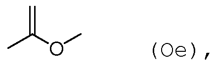
According to other embodiments, the hydrofluoromonoether contains exactly three or four or five or six carbon atoms, in particular exactly three or four carbon atoms, most preferably exactly three carbon atoms. More particularly, the hydrofluoromonoether is thus at least one compound selected from the group consisting of the compounds defined
19.05.2015 by the following structural formulae in which a part of the hydrogen atoms is each substituted by a fluorine atom:
(Oa) ,
Figure imgf000015_0001
(Oc) ,
(Od) ,
Figure imgf000015_0002
(Of) ,
(Og) ,
Figure imgf000015_0003
19.05.2015
Figure imgf000016_0001
By using a hydrofluoromonoether containing three or four carbon atoms, no liquefaction occurs under typical operational conditions of the apparatus. Thus, a dielectric insulation fluid, every component of which is in the gaseous state at operational conditions of the apparatus, can be achieved. Nevertheless, the boiling point of this hydro- fluoromonoether is still high enough to allow liquefaction by means of the liquefaction device of the present invention.
19.05.2015 Considering flammability of the compounds, it is further advantageous that the ratio of the number of fluorine atoms to the total number of fluorine and hydrogen atoms, here briefly called "F-rate", of the hydrofluoromonoether is at least 5:8. It has been found that compounds falling within this definition are generally non-flammable and thus result in an insulation medium complying with highest safety requirements. Thus, safety requirements of the electrical insulator and the method of its production can readily be fulfilled by using a corresponding hydrofluoromonoether .
According to other embodiments, the ratio of the number of fluorine atoms to the number of carbon atoms, here briefly called "F/C-ratio", ranges from 1.5:1 to 2:1. Such compounds generally have a GWP of less than 1' 000 over 100 years and are thus very environment-friendly. It is particularly preferred that the hydrofluoromonoether has a GWP of less than 700 over 100 years.
According to other embodiments of the present invention, the hydrofluoromonoether has the general structure (0) CaHbFc-0-CdHeFf (0) wherein a and d independently are an integer from 1 to 3 with a + d = 3 or 4 or 5 or 6, in particular 3 or 4, b and c independently are an integer from 0 to 11, in particular 0 to 7, with b + c = 2a + 1, and e and f independently are an integer from 0 to 11, in particular 0 to 7, with e + f = 2d + 1, with further at least one of b and e being 1 or greater and at least one of c and f being 1 or greater.
It is thereby a preferred embodiment that in the general structure or formula (0) of the hydrofluoromonoether : a is 1, b and c independently are an integer ranging from 0 to 3 with b + c = 3, d = 2, e and f independently are an integer ranging from 0 to 5 with e + f = 5, with further at least
19.05.2015 one of b and e being 1 or greater and at least one of c and f being 1 or greater.
According to a more particular embodiment, exactly one of c and f in the general structure (0) is 0. The corresponding grouping of fluorines on one side of the ether linkage, with the other side remaining unsubstituted, is called "segregation". Segregation has been found to reduce the boiling point compared to unsegregated compounds of the same chain length. Most preferably, the hydrofluoromonoether is selected from the group consisting of pentafluoro-ethyl-methyl ether (CH3- 0-CF2CF3) and 2, 2, 2-trifluoroethyl-trifluoromethyl ether (CF3-0-CH2CF3) .
Pentafluoro-ethyl-methyl ether has a boiling point of +5.25°C and a GWP of 697 over 100 years, the F-rate being 0.625, while 2 , 2 , 2-trifluoroethyl-trifluoromethyl ether has a boiling point of +11°C and a GWP of 487 over 100 years, the F-rate being 0.75. They both have an ODP of 0 and are thus environmentally fully acceptable. In addition, pentafluoro-ethyl-methyl ether has been found to be thermally stable at a temperature of 175°C for 30 days and therefore to be fully suitable for the operational conditions given in the apparatus. Since thermal stability studies of hydrofluoromonoethers of higher molecular weight have shown that ethers containing fully hydrogenated methyl or ethyl groups have a lower thermal stability compared to those having partially hydrogenated groups, it can be assumed that the thermal stability of 2, 2, 2-trifluoroethyl- trifluoromethyl ether is even higher. Hydrofluoromonoethers in general, and pentafluoro-ethyl- methyl ether as well as 2, 2, 2-trifluoroethyl-trifluoromethyl ether in particular, display a low risk of human toxicity.
19.05.2015 This can be concluded from the available results of mammalian HFC (hydrofluorocarbon ) tests. Also, information available on commercial hydrofluoromonoethers do not give any evidence of carcinogenicity, mutagenicity, reproductive or developmental effects and other chronic effects of the compounds of the present application.
Based on the data available for commercial hydrofluoro ethers of higher molecular weight, it can be concluded that the hydrofluoromonoethers , and in particular pentafluoro- ethyl-methyl ether as well as 2, 2, 2-trifluoroethyl- trifluoromethyl ether, have a lethal concentration LC 50 of higher than 10' 000 ppm, rendering them suitable also from a toxicological point of view.
The hydrofluoromonoethers mentioned have a higher dielectric strength than air. In particular, pentafluoro-ethyl-methyl ether at 1 bar has a dielectric strength about 2.4 times higher than that of air at 1 bar.
Given its boiling point, which is preferably below 55°C, more preferably below 40°C, in particular below 30°C, the hydrofluoromonoethers mentioned, particularly pentafluoro- ethyl-methyl ether and 2, 2, 2-trifluoroethyl-trifluoromethyl ether, respectively, are normally in the gaseous state at operational conditions. Thus, a dielectric insulation medium in which every component is in the gaseous state at operational conditions of the apparatus can be achieved, which is advantageous.
Alternatively or additionally to the hydrofluoromonoethers mentioned above, the respective insulation medium comprises a fluoroketone containing from four to twelve carbon atoms . The term "fluoroketone" as used in this application shall be interpreted broadly and shall encompass both perfluoro- ketones and hydrofluoroketones, and shall further encompass
19.05.2015 both saturated compounds and unsaturated compounds, i.e. compounds including double and/or triple bonds between carbon atoms. The at least partially fluorinated alkyl chain of the fluoroketones can be linear or branched, or can form a ring, which optionally is substituted by one or more alkyl groups. In exemplary embodiments, the fluoroketone is a perfluoroketone . In further exemplary embodiment, the fluoroketone has a branched alkyl chain, in particular an at least partially fluorinated alkyl chain. In still further exemplary embodiments, the fluoroketone is a fully saturated compound .
According to another aspect, the insulation medium according to the present invention can comprise a fluoroketone having from 4 to 12 carbon atoms, the at least partially fluorinated alkyl chain of the fluoroketone forming a ring, which is optionally substituted by one or more alkyl groups.
It is particularly preferred that the insulation medium comprises a fluoroketone containing exactly five or exactly six carbon atoms or mixtures thereof. Compared to fluoroketones having a greater chain length with more than six carbon atoms, fluoroketones containing five or six carbon atoms have the advantage of a relatively low boiling point, allowing to avoid liquefaction under operational conditions. Nevertheless, the boiling point of this fluoroketone is still high enough to allow liquefaction by means of the liquefaction device of the present invention.
According to embodiments, the fluoroketone is at least one compound selected from the group consisting of the compounds defined by the following structural formulae in which at least one hydrogen atom is substituted with a fluorine atom:
19.05.2015
Figure imgf000021_0001
19.05.2015
Figure imgf000022_0001
Fluoroketones containing five or more carbon atoms are further advantageous, because they are generally non-toxic with outstanding margins for human safety. This is in contrast to fluoroketones having less than four carbon atoms, such as hexafluoroacetone (or hexafluoropropanone ) , which are toxic and very reactive. In particular, fluoroketones containing exactly five carbon atoms, herein briefly named fluoroketones a) , and fluoroketones containing exactly six carbon atoms are thermally stable up to 500°C. According to a specific embodiment, the dielectric insulation medium according to the present invention, in particular comprising a fluoroketone having exactly 5 carbon atoms, can further comprise a background gas, in particular selected from the group consisting of: air, air component, nitrogen, oxygen, carbon dioxide, a nitrogen oxide (including but not limited to N02, NO, N20) , and mixtures thereof .
In embodiments of this invention, the fluoroketones, in particular fluoroketones a) , having a branched alkyl chain are preferred, because their boiling points are lower than the boiling points of the corresponding compounds (i.e. compounds with same molecular formula) having a straight alkyl chain.
According to embodiments, the fluoroketone a) is a per- fluoroketone, in particular has the molecular formula C5Fi0O, i.e. is fully saturated without double or triple bonds between carbon atoms. The fluoroketone a) may preferably be
19.05.2015 selected from the group consisting of 1,1,1,3,4,4,4- heptafluoro-3- (trifluoromethyl ) utan-2-one (also named deca- fluoro-2-methylbutan-3-one) , 1,1,1,3,3,4,4, 5, 5, 5-decafluoro- pentan-2-one, 1 , 1 , 1 , 2 , 2 , 4 , 4 , 5, 5, 5-decafluoropentan-3-one and octafluorocylcopentanone, and most preferably is 1,1,1,3,4,4, 4-heptafluoro-3- (trifluoromethyl ) butan-2-one .
1,1,1,3,4,4, 4-heptafluoro-3- (trifluoromethyl ) butan-2-one can be represented by the following structural formula (I) :
Figure imgf000023_0001
1,1,1,3,4,4, 4-heptafluoro-3- (trifluoromethyl ) butan-2-one, here briefly called "C5-ketone", with molecular formula CF3C (0) CF (CF3) 2 or C5F10O, has been found to be particularly preferred for high and medium voltage insulation appli¬ cations, because it has the advantages of high dielectric insulation performance, in particular in mixtures with a dielectric carrier gas, has very low GWP and has a low boiling point. It has an ODP of 0 and is practically non¬ toxic .
According to embodiments, even higher insulation capabili- ties can be achieved by combining the mixture of different fluoroketone components. In embodiments, a fluoroketone containing exactly five carbon atoms, as described above and here briefly called fluoroketone a) , and a fluoroketone containing exactly six carbon atoms or exactly seven carbon atoms, here briefly named fluoroketone c) , can favourably be part of the dielectric insulation at the same time. Thus, an insulation medium can be achieved having more than one
19.05.2015 fluoroketone, each contributing by itself to the dielectric strength of the insulation medium.
In embodiments, the further fluoroketone c) is at least one compound selected from the group consisting of the compounds defined by the following structural formulae in which at least one hydrogen atom is substituted with a fluorine atom:
Figure imgf000024_0001
O (Hf), and
Figure imgf000024_0002
as well as any fluoroketone having exactly 6 carbon atoms, in which the at least partially fluorinated alkyl chain of the fluoroketone forms a ring, which is substituted by one or more alkyl groups (Ilh) ;
19.05.2015 and/or is at least one compound selected from the group consisting of the compounds defined by the following structural formulae in which at least one hydrogen atom is substituted with a fluorine atom:
Figure imgf000025_0001
(Hie) ,
Figure imgf000025_0002
19.05.2015
Figure imgf000026_0001
(HI j) r
Figure imgf000026_0002
(Illk) ,
Figure imgf000026_0003
( Illm) , and
Figure imgf000026_0004
(ΙΙΙη) , in particular dodecafluoro- cycloheptanone, as well as any fluoroketone having exactly 7 carbon atoms, in which the at least partially fluorinated alkyl chain of the fluoroketone forms a ring, which is substituted by one or more alkyl groups (IIIo) .
The present invention encompasses each compound or each combination of compounds selected from the group consisting of the compounds according to structural formulae (la) to (Ii) , (Ha) to (Ilh) , (Ilia) to (IIIo) , and mixtures thereof .
According to another aspect, the dielectric insulation medium according to the present invention can comprise a fluoroketone having exactly 6 carbon atoms, in which the at least partially fluorinated alkyl chain of the fluoroketone
19.05.2015 forms a ring, optionally substituted by one or more alkyl groups . Furthermore, such dielectric insulation medium can comprise a background gas, in particular selected from the group consisting of: air, air component, nitrogen, oxygen, carbon dioxide, a nitrogen oxide (including but not limited to N02, NO, N20) , and mixtures thereof. Furthermore, an electrical apparatus comprising such a dielectric insulation medium is disclosed.
According to still another aspect, the dielectric insulation medium according to the present invention can comprise a fluoroketone having exactly 7 carbon atoms, in which the at least partially fluorinated alkyl chain of the fluoroketone forms a ring, optionally substituted by one or more alkyl groups . Furthermore, such dielectric insulation medium can comprise a background gas, in particular selected from the group consisting of: air, air component, nitrogen, oxygen, carbon dioxide, a nitrogen oxide (including but not limited to N02, NO, N20) , and mixtures thereof. Furthermore, an electrical apparatus comprising such a dielectric insulation fluid is disclosed.
The present invention encompasses any dielectric insulation medium comprising each compound or each combination of compounds selected from the group consisting of the compounds according to structural formulae (la) to (Ii), (Ha) to (Ilg) , (Ilia) to (ΙΙΙη) , and mixtures thereof, and with the dielectric insulation medium further comprising a background gas, in particular selected from the group consisting of: air, air component, nitrogen, oxygen, carbon dioxide, a nitrogen oxide (including but not limited to N02, NO, N20) , and mixtures thereof. Furthermore, an electrical apparatus comprising such a dielectric insulation medium is disclosed.
19.05.2015 Depending on the specific application of the electrical component of the apparatus of the present invention, a fluoroketone containing exactly six carbon atoms (falling under the designation "fluoroketone c)" mentioned above) may be preferred for the respective insulation space compartment; such a fluoroketone is non-toxic, with outstanding margins for human safety.
In embodiments, fluoroketone c) , alike fluoroketone a) , is a perfluoroketone , and/or has a branched alkyl chain, in particular an at least partially fluorinated alkyl chain, and/or the fluoroketone c) contains fully saturated compounds. In particular, the fluoroketone c) has the molecular formula C6Fi20, i.e. is fully saturated without double or triple bonds between carbon atoms. More preferably, the fluoroketone c) can be selected from the group consisting of 1, 1, 1, 2, 4, 4, 5, 5, 5-nonafluoro-2-
(trifluoromethyl) pentan-3-one (also named dodecafluoro-2- methylpentan-3-one) , 1, 1, 1, 3,3,4, 5, 5, 5-nonafluoro-4-
(trifluoromethyl) pentan-2-one (also named dodecafluoro-4- methylpentan-2-one) , 1, 1, 1, 3, 4, 4, 5, 5, 5-nonafluoro-3-
(trifluoromethyl) pentan-2-one (also named dodecafluoro-3- methylpentan-2-one ) , 1,1,1,4,4, 4-hexafluoro-3, 3-bis-
(trifluoromethyl) butan-2-one (also named dodecafluoro-3, 3-
(dimethyl ) butan-2-one ) , dodecafluorohexan-2-one, dodecafluorohexan-3-one and decafluorocyclohexanone (with sum formula C6Fi0O) , and particularly is the mentioned 1,1,1,2,4,4,5,5, 5-nonafluoro-2- (trifluoromethyl ) pentan-3- one .
1,1,1,2,4,4,5,5, 5-Nonafluoro-2- (trifluoromethyl ) pentan-3-one (also named dodecafluoro-2-methylpentan-3-one) can be represented by the following structural formula (II) :
19.05.2015
Figure imgf000029_0001
(ID
1,1,1,2,4,4,5,5, 5-Nonafluoro-4 - (trifluoromethyl ) pentan-3-one (here briefly called "C6-ketone", with molecular formula C2F5C (0) CF (CF3) 2) has been found to be particularly preferred for high voltage insulation applications because of its high insulating properties and its extremely low GWP . Specifically, its pressure-reduced breakdown field strength is around 240 kV/ (cm*bar) , which is much higher than the one of air having a much lower dielectric strength (Ecr = 25 kV/ (cm*bar) . It has an ozone depletion potential of 0 and is non-toxic. Thus, the environmental impact is much lower than when using SF6, and at the same time outstanding margins for human safety are achieved.
As mentioned above, the organofluorine compound can also be a fluoroolefin, in particular a hydrofluoroolefin . More particularly, the fluoroolefin or hydrofluorolefin contains exactly three carbon atoms.
According to an embodiment, the hydrofluoroolefin is thus selected from the group consisting of: 1, 1, 1, 2-tetrafluoro- propene (HFO-1234yf) , 1, 2, 3, 3-tetrafluoro-2-propene (HFO- 1234yc), 1, 1, 3, 3-tetrafluoro-2-propene (HFO-1234zc) ,
1, 1, 1, 3-tetrafluoro-2-propene (HFO-1234ze) , 1 , 1 , 2 , 3-tetra- fluoro-2-propene (HFO-1234ye) , 1 , 1 , 1 , 2 , 3-pentafluoropropene (HFO-1225ye) , 1, 1, 2, 3, 3-pentafluoropropene (HFO-1225yc) , 1, 1, 1, 3, 3-pentafluoropropene (HFO-1225zc) , (Z) 1,1, 1,3- tetrafluoropropene (HFO-1234zeZ ) , (Z) 1, 1, 2, 3-tetrafluoro-2- propene (HFO-1234yeZ) , (E) 1, 1, 1, 3-tetrafluoropropene (HFO- 1234zeE), (E) 1, 1, 2, 3-tetrafluoro-2-propene (HFO-1234yeE ) ,
19.05.2015 (Z) 1, 1, 1, 2, 3-pentafluoropropene (HFO-1225yeZ ) , (E ) 1 , 1 , 1 , 2 , 3- pentafluoropropene (HFO-1225yeE) and combinations thereof.
In embodiments, the organofluorine compound can also be a fluoronitrile, in particular a perfluoronitrile . In particu- lar, the organofluorine compound can be a fluoronitrile, specifically a perfluoronitrile, containing two carbon atoms, and/or three carbon atoms, and/or four carbon atoms.
More particularly, the fluoronitrile can be a perfluoro- alkylnitrile, specifically perfluoroacetonitrile, perfluoro- propionitrile (C2F5CN) and/or perfluorobutyronitrile (C3F7CN) .
Most particularly, the fluoronitrile can be perfluoro- isobutyronitrile (according to the formula (CF3)2CFCN) and/or perfluoro-2-methoxypropanenitrile (according to formula CF3CF (OCF3 ) CN) . Of these, perfluoroisobutyronitrile is particularly preferred due to its low toxicity.
In general embodiments of the electrical apparatus or method for recovering, the organofluorine compound can be selected from the group consisting of: a fluoroether, an oxirane, a fluoroamine, a fluoroketone, a fluoroolefin, a fluoronitrile, and mixtures and/or decomposition products thereof. Herein, the terms "fluoroether", "oxirane", "fluoroamine", "fluoroketone", "fluoroolefin" , and "fluoro- nitrile" refer to at least partially fluorinated compounds. In particular, the term "fluoroether" encompasses both fluoropolyethers (e.g. galden) and fluoromonoethers as well as both hydrofluoroethers and perfluoroethers , the term "oxirane" encompasses both hydrofluorooxiranes and perfluorooxiranes , the term "fluoroamine" encompasses both hydrofluoroamines and perfluoroamines , the term "fluoro- ketone" encompasses both hydrofluoroketones and perfluoro- ketones, the term "fluoroolefin" encompasses both hydro- fluoroolefins and perfluoroolefins , and the term "fluoro- nitrile" encompasses both hydrofluoronitriles and
19.05.2015 perfluoronitriles . It can thereby be preferred that the fluoroether, the oxirane, the fluoroamine, the fluoroketone and the fluoronitrile are fully fluorinated, i.e. perfluorinated . In embodiments, the dielectric insulation medium can further comprise a background gas or carrier gas different from the organofluorine compound (in particular different from the fluoroether, the oxirane, the fluoroamine, the fluoroketone, the fluoroolefin and the fluoronitrile ) and can in embodiments be selected from the group consisting of: air, N2, 02, C02, a noble gas, H2; N02, NO, N20; fluorocarbons and in particular perfluorocarbons , such as CF4; CF3I, SF6; and mixtures thereof.
According to further embodiments, the electrical apparatus is selected from the group consisting of: a switchgear, in particular a gas-insulated switchgear (GIS) , or a part and/or component thereof, a busbar, a bushing, a cable, a gas-insulated cable, a cable joint, a gas-insulated line (GIL) , a transformer, a current transformer, a voltage transformer, a surge arrester, an earthing switch, a disconnector, a combined disconnector and earthing switch, a load-break switch, a circuit breaker, any type of gas- insulated switch, a high voltage apparatus, a medium voltage apparatus, a low voltage apparatus, a direct-current apparatus, an air-insulated insulator, a gas-insulated metal-encapsulated insulator, sensors, a capacitor, an inductance, a resistor, a current limiter, a high voltage switch, a gas circuit breaker, a vacuum circuit breaker, a generator circuit breaker, a medium voltage switch, a ring main unit, a recloser, a sectionalizer, a low voltage switch, a distribution transformer, a power transformer, a tap changer, a transformer bushing, a power semiconductor device, a power converter, a converter station, a convertor building, a computing machine, and components and/or combinations of such devices.
19.05.2015 In addition to the apparatus described above, the present invention further relates to a method for recovering a substance from an insulation medium of an electrical apparatus for the generation, transmission, distribution and/or usage of electrical energy, the insulation medium comprising an organofluorine compound and at least one further component. The method comprises the steps of: a) conveying an initial gas mixture containing the organo- fluorine compound and at least one further component of the insulation medium out of the insulation space into a substance recovery device,
b) liquefying and/or solidifying the organofluorine compound in the substance recovery device, and
c) separating the liquefied and/or solidified organofluorine compound from the at least one remaining component of the initial gas mixture .
As mentioned above in connection with the apparatus of the present invention, the organofluorine compound can be recycled into the insulation space, which is highly advantageous from both an economic as well as an ecologic point of view.
The method of the present invention further allows evacuation of the insulation space by means of a pump, in particular a suction pump, without facing the problem of liquefaction in the pressurization zone of the pump. This is achieved by simply arranging the pump downstream of the substance recovery device, as discussed above. Thus, replacement of the insulation medium can be carried out in a very safe manner. All features which are described as preferable for the apparatus are also to be considered preferable for the method of the present invention, and vice versa.
19.05.2015 According to an embodiment, steps a) to c) are subsequent steps. It is further preferred that in step b) , only the organofluorine compound is liquefied and/or solidified.
As also mentioned in connection with the apparatus of the present invention, the initial gas mixture is preferably cooled below the dew point of the organofluorine compound for liquefying and/or solidifying the organofluorine compound according to step b) .
In further embodiments, the initial gas mixture is preferably purified from liquid and/or solid impurities by a filter before being conveyed to the substance recovery device according to step a) . As mentioned above, the risk of clogging of the substance recovery device, and ultimately of a failure of the device, can be efficiently reduced by this purification step.
In further embodiments, the method preferably comprises the further step of :
d) collecting the condensed organofluorine compound by an organofluorine compound collecting device.
In further embodiments, after step c) or optionally after step d) , the method comprises the further step of :
e) conveying the organfluorine compound to an organofluorine compound reservoir tank for being stored therein.
The method allows, after step c) or optionally after step d) or e) , the further step of:
f) reintroducing the organofluorine compound into the insulation space,
which contributes to the economic and ecologic benefits of the present invention.
19.05.2015 The initial gas mixture is preferably conveyed by means of a suction pump. Alternatively or additionally, it can further be conveyed by purging the insulation space, thereby forcing the initial gas mixture out of the insulation space. The pump used for purging the insulation space can be identical to the suction pump mentioned above, in which case both the pump inlet as well as the pump outlet are connected to the insulation space, such that a flow of gas from the insulation space to the pump is generated on the suction side and a flow of gas from the pump to the insulation space is generated on the discharge side of the pump.
In embodiments also disclosed in connection with the apparatus of the present invention described above, the at least one remaining component of the initial gas mixture is preferably conveyed to a secondary reservoir tank for being stored therein.
In yet further embodiments the at least one remaining component of the initial gas mixture is reintroduced into the insulation space, and, according to a particularly preferred embodiment, is purified before being reintroduced into the insulation space.
The present invention is further illustrated by way of the attached
Fig. 1 showing schematically an electrical apparatus comprising a substance recovery device according to the present invention.
Fig. 1 shows the electrical apparatus 10 of the present invention comprising a housing 12 enclosing an electrical apparatus interior space. The electrical apparatus interior space forms or comprises an insulation space 16, in which an electrical component 14 is arranged. The electrical component 14 can for example be connected to respective
19.05.2015 conductors 18a, 18b which are insulated from the material of the housing 12 by means of respective bushings. The electrical component 14 is surrounded by an insulation medium 22 which comprises an organofluorine compound and a background gas and hence separates and electrically insulates the housing 12 from the electrical component 14.
The apparatus 10 further comprises a gas flow generating device 24 designed to generate a flow of an initial gas mixture through an outlet opening 26 arranged in the housing 12 out of the insulation space 16. In the embodiment shown, the gas flow generating device 24 is in the form of a suction pump 241.
The initial gas mixture contains the organofluorine compound and at least one further component . This further component can in particular be the background gas or a background gas component, but can also be a decomposition product generated from the organofluorine compound.
The outlet opening 26 opens out into a primary gas channel 28 which fluidly connects the insulation space 16 with a substance recovery device 30. Between the outlet opening 26 and the substance recovery device 30, a filter 32 can be arranged, which is designed such to remove solid or liquid impurities from the flow of the initial mixture prior to entering the substance recovery device 30. The substance recovery device 30 comprises a separator 34 for separating - or, in general throughout this disclosure, comprises a separator 34 having means for separating or being designed to separate - the organofluorine compound from the at least one remaining component of the initial gas mixture. For this purpose, the separator 34 comprises in the embodiment shown a liquefaction device 36 adapted for liquefying the organofluorine compound. In the embodiment
19.05.2015 shown, the liquefaction device 36 is in the form of a cooler 361 for cooling the initial gas mixture below the dew point of the organofluorine compound. Additionally or alternative¬ ly, the liquefaction device can also be or comprise a compressor for liquefying the organofluorine compound by a pressure increase.
For collecting the organofluorine compound separated by the separator 34, the apparatus canfurther comprise an organo- fluorine compound collecting device 38. The organofluorine compound collecting device 38 can e.g. be in the form of a funnel 381, as schematically indicated in Fig. 1, and leads in the embodiment shown to an organofluorine compound reservoir tank 40 for storing the organofluorine compound.
In embodiments, the organoflourine compound collecting device 38 is arranged below the separator 34 to allow the liquefied organofluorine compound to flow downward or the solidified organofluorine compound to fall downward into the organoflourine compound collecting device 38.
From the organofluorine compound reservoir tank 40 of the substance recovery device 30, an organofluorine compound recycling channel 42 leads to an organofluorine compound inlet opening 44 arranged in the housing 12 and designed such to reintroduce the organofluorine compound into the insulation space 16. From the separator 34 of the substance recovery device 30, a secondary gas channel 46 branches off. By means of the suction pump 241, which is arranged downstream of the substance recovery device 30, the at least one remaining component of the initial gas mixture without the organofluorine compound is guided through the secondary gas channel 46 and is led to a secondary reservoir tank 48 for storing the at least one remaining component of the initial
19.05.2015 gas mixture. In this regard, the suction pump 241 also functions as a compressor for compressing the remaining components .
The secondary reservoir tank 48 is fluidly connected to a gas inlet opening 50 arranged in the housing 12 for reintroducing the at least one remaining component of the initial gas mixture into the insulation space 16. In the embodiment shown, the gas inlet opening 50 is in the form of a secondary gas inlet 501 opening separate from the organofluorine compound inlet opening 44.
19.05.2015 List of reference numerals
10 electrical apparatus
12 housing
14 electrical component
16 insulation space
18a, 18b conductors
22 insulation medium
24; 241 gas flow generating device
241 pump, suction pump
26 outlet opening
28 primary gas channel
30 substance recovery device
32 filter
34 separator
36; 361 liquefaction device
361 cooler
38; 381 organofluorine compound collecting device
381 funnel
40 organofluorine compound reservoir tank
42 organofluorine compound recycling channel
44 organofluorine compound inlet opening
46 secondary gas channel
48 secondary reservoir tank
50; 501 gas inlet opening for reintroducing the at least one remaining component; secondary gas inlet opening .
19.05.2015

Claims

Electrical apparatus (10) for generation, transmission, distribution and/or usage of electrical energy, the electrical apparatus (10) comprising a housing (12) enclosing an electrical apparatus interior space, at least a portion of said electrical apparatus interior space comprising at least one insulation space (16), in which an electrical component (14) is arranged and which contains an insulation medium (22) surrounding the electrical component (14), the insulation medium (22) comprising an organofluorine compound and at least one further component in gaseous phase,
the electrical apparatus (10) further comprising a gas flow generating device (24) designed to generate a flow of an initial gas mixture through an outlet opening (26) arranged in the housing (12) out of the insulation space (16), the initial gas mixture containing the organofluorine compound and at least one further component of the insulation medium,
wherein downstream of the outlet opening (26) a substance recovery device (30) is arranged, the substance recovery device (30) comprising a separator (34) for separating the organofluorine compound from the at least one remaining component of the initial gas mixture, said separator (34) being or comprising a liquefaction device (36) adapted for liquefying and/or a solidification device adapted for solidifying the organofluorine compound.
Electrical apparatus (10) according to claim 1, wherein the initial gas mixture is at least essentially identical to the insulation medium (22) . 15 Electrical apparatus (10) according to any one of the preceding claims, wherein the liquefaction device (36) is specifically adapted for liquefying the organo- fluorine compound only, and/or the solidification device is specifically adapted for solidifying the organofluorine compound only.
Electrical apparatus (10) according to any one of the preceding claims, wherein the liquefaction device (36) and/or the solidification device is or comprises a cooler (361) for cooling the initial gas mixture down to a temperature below the dew point of the organofluorine compound.
Electrical apparatus (10) according to any one of the preceding claims, wherein the outlet opening (26) opens into a primary gas channel (28), which fluidically connects the insulation space (16) with the substance recovery device (30) .
Electrical apparatus (10) according to any one of the preceding claims, wherein the substance recovery device (30) further comprises an organoflourine compound collecting device (38) for collecting the organo- fluorine compound separated by the separator (34), in particular wherein the organoflourine compound collecting device (38) is arranged below the separator (34) to allow the liquefied organofluorine compound to flow downward or the solidified organofluorine compound to fall downward into the organoflourine compound collecting device (38) .
Electrical apparatus (10) according to any one of the preceding claims, wherein the substance recovery device (30) further comprises at least one organofluorine compound reservoir tank (40) for storing the organo- fluorine compound separated by the separator (34) . 015
8. Electrical apparatus (10) according to any one of the preceding claims, the apparatus (10) further comprising a filter (32) arranged between the outlet opening (26) and the substance recovery device (30) and designed such to remove solid or liquid impurities from the flow of the initial gas mixture.
9. Electrical apparatus (10) according to any one of the preceding claims, the apparatus (10) further comprising an organofluorine compound recycling channel (42) leading from the substance recovery device (30) to an organofluorine compound inlet opening (44) arranged in the housing (12) and designed such to reintroduce the organofluorine compound into the insulation space (16) .
10. Electrical apparatus (10) according to claim 9, wherein upstream of the organofluorine compound inlet opening
(44) an organofluorine compound treatment device is arranged, in particular for removing impurities from the organofluorine compound to be reintroduced into the insulation space (16) . 11. Electrical apparatus (10) according to any one of the preceding claims, wherein the gas stream generating device (24) is or comprises a pump (241) .
12. Electrical apparatus (10) according to any one of the preceding claims, wherein the pump is a suction pump (241) and is arranged downstream of the substance recovery device (30) .
13. Electrical apparatus (10) according to any one of the preceding claims, wherein the pump (241) is designed such to purge the insulation space (16), thereby forcing the initial gas mixture out of the insulation space (16) .
19.05.2015
14. Electrical apparatus (10) according to any one of the preceding claims, wherein from the separator (34) of the substance recovery device (30) at least one secondary gas channel (46) branches off, the secondary gas channel (46) being adapted for guiding the at least one remaining component of the initial gas mixture without the organofluorine compound.
15. Electrical apparatus (10) according to claim 14, wherein the secondary gas channel (46) leads to a secondary reservoir tank (48) for storing the at least one remaining component of the initial gas mixture.
16. Electrical apparatus (10) according to claim 14 or 15, wherein the secondary gas channel (46), and optionally the secondary reservoir tank (48), is fluidly connected to a gas inlet opening (50) arranged in the housing
(12) for reintroducing the at least one remaining component of the initial gas mixture into the insulation space (16) .
17. Electrical apparatus (10) according to claim 16, wherein upstream of the gas inlet opening (50) a secondary treatment device is arranged, in particular for purifying the at least one remaining component of the initial gas mixture.
18. Electrical apparatus (10) according to any one of the preceding claims, wherein the organofluorine compound is selected from the group consisting of fluoroethers, in particular hydrofluoromonoethers , fluoroketones, fluoroolefins, in particular hydrofluoroolefins, and mixtures thereof. 19. Electrical apparatus (10) according to any one of the preceding claims, wherein the insulation medium (22)
19.05.2015 comprises a hydrofluoromonoether containing at least three carbon atoms.
Electrical apparatus (10) according to any one of the preceding claims, wherein the insulation medium (22) comprises a fluoroketone containing from four to twelve carbon atoms, preferably containing exactly five carbon atoms or exactly six carbon atoms, or a mixture thereof .
Electrical apparatus (10) according to any one of the preceding claims, characterized in that the at least one further component is selected from the group consisting of air, an air component, nitrogen, oxygen, carbon dioxide, a nitrogen oxide, and mixtures thereof.
Electrical apparatus (10) according to any oen of the preceding claims, characterized in that the electrical component (14) is a high voltage or medium voltage apparatus, or is a high voltage or medium voltage component .
23. Electrical apparatus (10) according to any one of the preceding claims, characterized in that the apparatus
(10) is selected from the group consisting of: switchgear, in particular a gas-insulated switchgear
(GIS) , or a part and/or component thereof, busbar, bushing, cable, gas-insulated cable, cable joint, gas- insulated line (GIL) , transformer, current transformer, voltage transformer, surge arrester, earthing switch, disconnector, combined disconnector and earthing switch, load-break switch, circuit breaker, any type of gas-insulated switch, high voltage apparatus, medium voltage apparatus, low voltage apparatus, direct- current apparatus, air-insulated insulator, gas-insula¬ ted metal-encapsulated insulator, sensors, capacitor,
19.05.2015 inductance, resistor, current limiter, high voltage switch, gas circuit breaker, vacuum circuit breaker, generator circuit breaker, medium voltage switch, ring main unit, recloser, sectionalizer, low voltage switch, distribution transformer, power transformer, tap changer, transformer bushing, power semiconductor device, power converter, converter station, convertor building, computing machine, and components and/or combinations of such devices.
Electrical apparatus (10) according to any one of the preceding claims, characterized in that the separator (34) is a liquefaction device (36) that provides a phase transition of the organofluorine compound from gaseous phase to liquid phase, and in particular does not provide a phase transition of the at least one remaining component of the initial gas mixture.
Electrical apparatus (10) according to any one of the preceding claims, characterized in that the separator (34) is a solidification device (36) that provides a phase transition of the organofluorine compound from gaseous phase to solid phase, and in particular does not provide a phase transition of the at least one remaining component of the initial gas mixture.
Method for recovering a substance from an insulation medium (22) of an electrical apparatus (10) for the generation, transmission, distribution and/or usage of electrical energy, the insulation medium (22) comprising an organofluorine compound and at least one further component in gaseous phase, said method comprising the method elements of:
a) conveying an initial gas mixture containing the organofluorine compound and at least one further component of the insulation medium (22) out of the insulation space (16) into a substance recovery device (30 ) ,
b) liquefying and/or solidifying the organofluorine compound in the substance recovery device (30), and c) separating the liquefied and/or solidified organo- fluorine compound from the at least one remaining component of the initial gas mixture.
27. Method according to claim 26, wherein the method elements a) to c) are subsequent steps a) to c) .
28. Method according to claim 26 or 27, wherein in method element b) , only the organofluorine compound is liquefied and/or solidified.
29. Method according to any one of the claims 26 to 28, wherein for liquefying and/or solidifying the organofluorine compound according to method element b) , the initial gas mixture is cooled below the dew point of the organofluorine compound.
30. Method according to any one of the claims 26 to 29, wherein the initial gas mixture is purified from liquid and/or solid impurities by a filter (32) before being conveyed to the substance recovery device (30) according to the method element a) .
31. Method according to any one of the claims 26 to 30, wherein after method element c) , the method comprises the further method element of :
d) collecting the condensed organofluorine compound by an organofluorine compound collecting device (38) .
19.05.2015
32. Method according to any of the claims 26 to 31, wherein after step c) or optionally d) , the method comprises the further method element of :
e) conveying the organfluorine compound to an organo- fluorine compound reservoir tank (40) for being stored.
33. Method according to any one of the claims 26 to 32, wherein after method element c) , or optionally after method element d) or e), the method comprises the further method element of :
f) reintroducing the organofluorine compound into the insulation space (16) .
34. Method according to claim 33, wherein before being reintroduced into the insulation space (16), the organofluorine compound is treated, in particular by removing impurities from the organofluorine compound.
35. Method according to any one of the claims 26 to 34, wherein the initial gas mixture is conveyed by means of a suction pump (241) . 36. Method according to any one of the claims 26 to 35, wherein the initial gas mixture is conveyed by purging the insulation space (16), thereby forcing the initial gas mixture out of the insulation space (16) .
37. Method according to any one of the claims 26 to 36, wherein the at least one remaining component of the initial gas mixture is conveyed to a secondary reservoir tank (48) for being stored.
19.05.2015
38. Method according to any one of the claims 26 to 37, wherein the at least one remaining component of the initial gas mixture is reintroduced into the insulation space (16) . 39. Method according to claim 38, wherein before being reintroduced into the insulation space (16) , the at least one remaining component of the initial gas mixture is purified.
19.05.2015
PCT/EP2015/060994 2014-05-20 2015-05-19 Electrical apparatus for the generation, transmission, distribution and/or usage of electrical energy and method for recovering a substance from an insulation medium of such an apparatus Ceased WO2015177149A1 (en)

Priority Applications (6)

Application Number Priority Date Filing Date Title
MX2016014972A MX2016014972A (en) 2014-05-20 2015-05-19 Electrical apparatus for the generation, transmission, distribution and/or usage of electrical energy and method for recovering a substance from an insulation medium of such an apparatus.
CA2949581A CA2949581A1 (en) 2014-05-20 2015-05-19 Electrical apparatus for the generation, transmission, distribution and/or usage of electrical energy and method for recovering a substance from an insulation medium of such an apparatus
EP15723932.8A EP3146531B2 (en) 2014-05-20 2015-05-19 Electrical apparatus for the generation, transmission, distribution and/or usage of electrical energy and method for recovering a substance from an insulation medium of such an apparatus
CN201580025971.4A CN106537705B (en) 2014-05-20 2015-05-19 Electrical equipment for the generation, transmission, distribution and/or use of electrical energy and methods for recovering substances from the insulating medium of such equipment
AU2015261942A AU2015261942A1 (en) 2014-05-20 2015-05-19 Electrical apparatus for the generation, transmission, distribution and/or usage of electrical energy and method for recovering a substance from an insulation medium of such an apparatus
US15/356,991 US10256008B2 (en) 2014-05-20 2016-11-21 Electrical apparatus for the generation, transmission, distribution and/or usage of electrical energy and method for recovering a substance from an insulation medium of such an apparatus

Applications Claiming Priority (2)

Application Number Priority Date Filing Date Title
EPPCT/EP2014/060300 2014-05-20
EP2014060300 2014-05-20

Related Child Applications (1)

Application Number Title Priority Date Filing Date
US15/356,991 Continuation US10256008B2 (en) 2014-05-20 2016-11-21 Electrical apparatus for the generation, transmission, distribution and/or usage of electrical energy and method for recovering a substance from an insulation medium of such an apparatus

Publications (1)

Publication Number Publication Date
WO2015177149A1 true WO2015177149A1 (en) 2015-11-26

Family

ID=50842238

Family Applications (1)

Application Number Title Priority Date Filing Date
PCT/EP2015/060994 Ceased WO2015177149A1 (en) 2014-05-20 2015-05-19 Electrical apparatus for the generation, transmission, distribution and/or usage of electrical energy and method for recovering a substance from an insulation medium of such an apparatus

Country Status (7)

Country Link
US (1) US10256008B2 (en)
EP (1) EP3146531B2 (en)
CN (1) CN106537705B (en)
AU (1) AU2015261942A1 (en)
CA (1) CA2949581A1 (en)
MX (1) MX2016014972A (en)
WO (1) WO2015177149A1 (en)

Cited By (6)

* Cited by examiner, † Cited by third party
Publication number Priority date Publication date Assignee Title
US20150083979A1 (en) * 2012-04-04 2015-03-26 3M Innovative Properties Company Fluorinated Nitriles as Dielectric Gases
WO2017029338A1 (en) 2015-08-19 2017-02-23 Abb Schweiz Ag Method for reclaiming at least one substance from an insulation medium of an electrical apparatus for the generation, transmission, distribution and/or usage of electrical energy
EP3546055A1 (en) * 2018-03-28 2019-10-02 ABB Schweiz AG Method for decomposing a fluoroketone into disposable decomposition products
EP3764382A1 (en) * 2016-06-03 2021-01-13 ABB Schweiz AG Gas-insulated low- or medium-voltage load break switch
US11456132B2 (en) 2018-07-27 2022-09-27 Siemens Energy Global GmbH & Co. KG Electrical switching device
US20230368938A1 (en) * 2022-04-28 2023-11-16 Eaton Intelligent Power Limited Gas mixture including a fluorinated nitrile for gas-insulated switchgear

Families Citing this family (9)

* Cited by examiner, † Cited by third party
Publication number Priority date Publication date Assignee Title
DE102017220570A1 (en) * 2017-11-17 2019-05-23 Siemens Aktiengesellschaft Insulation medium for an electric power transmission device
WO2019106840A1 (en) * 2017-12-01 2019-06-06 株式会社 東芝 Gas circuit breaker
FR3079359B1 (en) * 2018-03-22 2020-10-09 Arkema France USE OF 1-CHLORO-2,3,3,3-TETRAFLUOROPROPENE FOR INSULATING OR EXTINGUISHING ELECTRIC ARCS
US11978600B2 (en) * 2019-06-21 2024-05-07 Hitachi Energy Ltd Dielectric-insulation or arc-extinction fluid
CN111077391A (en) * 2019-12-20 2020-04-28 中国能源建设集团江苏省电力设计院有限公司 A real-time monitoring system for GIL lines
EP3923301B1 (en) * 2020-06-11 2022-09-07 General Electric Technology GmbH Gas-insulated electrical apparatus comprising carbon dioxide, heptafluoroisobutyronitrile and a high content of oxygen
CN111745351B (en) * 2020-06-15 2021-09-17 中国长江电力股份有限公司 500kV welding type GIL equipment tapping overhauling construction method
EP4304759A4 (en) * 2021-03-12 2025-01-15 3M Innovative Properties Company FLUORINATED FLUID CONDITIONING SYSTEM
CN118904008A (en) * 2024-10-08 2024-11-08 北京九章环境工程股份有限公司 Process method for recycling organic solvent at low temperature and low energy consumption

Citations (5)

* Cited by examiner, † Cited by third party
Publication number Priority date Publication date Assignee Title
US7128133B2 (en) 2003-12-16 2006-10-31 3M Innovative Properties Company Hydrofluoroether as a heat-transfer fluid
WO2010142346A1 (en) 2009-06-12 2010-12-16 Abb Technology Ag Dielectric insulation medium
WO2012080246A1 (en) 2010-12-14 2012-06-21 Abb Technology Ag Dielectric insulation medium
WO2012080222A1 (en) 2010-12-14 2012-06-21 Abb Research Ltd Dielectric insulation medium
WO2014053661A1 (en) 2012-10-05 2014-04-10 Abb Technology Ag Apparatus containing a dielectric insulation gas comprising an organofluorine compound

Family Cites Families (27)

* Cited by examiner, † Cited by third party
Publication number Priority date Publication date Assignee Title
FR1265731A (en) 1960-08-23 1961-06-30 Thomson Houston Comp Francaise Improvements to the insulation of high voltage equipment
JP3237514B2 (en) 1996-04-23 2001-12-10 三菱電機株式会社 Sulfur hexafluoride gas recovery and regeneration device and mobile recovery and regeneration device
JPH10230124A (en) 1997-02-21 1998-09-02 Toshiba Corp SF6 gas recovery and purification equipment
JP3356965B2 (en) 1997-06-20 2002-12-16 株式会社日立製作所 SF6 gas recovery / purification processing apparatus and method
JP2000102123A (en) 1998-09-25 2000-04-07 Mitsubishi Electric Corp Condensable gas recovery device
JP2000274938A (en) 1999-03-23 2000-10-06 Toshiba Corp Gas recovery equipment
JP2000288331A (en) 1999-04-02 2000-10-17 Mitsubishi Electric Corp Condensable gas recovery device for recovering condensable gas from mixed gas and condensable gas recovery method using the same
JP2001103626A (en) 1999-09-30 2001-04-13 Toshiba Corp Gas recovery equipment
JP4357046B2 (en) 1999-10-01 2009-11-04 株式会社東芝 Gas recovery device
JP2001143580A (en) 1999-11-10 2001-05-25 Toshiba Corp Gas separation and recovery equipment
JP2001283692A (en) 2000-03-30 2001-10-12 Toshiba Corp SF6 gas separation and recovery device
JP4405039B2 (en) 2000-04-28 2010-01-27 株式会社東芝 Gas recovery device and gas recovery method
JP2001334117A (en) 2000-05-26 2001-12-04 Mitsubishi Electric Corp Mixed gas recovery method and apparatus
US7807074B2 (en) 2006-12-12 2010-10-05 Honeywell International Inc. Gaseous dielectrics with low global warming potentials
DE202009009305U1 (en) 2009-06-17 2009-11-05 Ormazabal Gmbh Switching device for medium, high or very high voltage with a filling medium
FR2965120B1 (en) 2010-09-22 2012-10-12 Areva T & D Sas APPARATUS FOR BREAKING A MEDIUM OR HIGH VOLTAGE ELECTRIC CURRENT AND METHOD FOR MANUFACTURING THE SAME
CA2821158A1 (en) * 2010-12-16 2012-06-21 Abb Technology Ag Dielectric insulation medium
FR2975836B1 (en) 2011-05-24 2014-07-04 Schneider Electric Ind Sas ELECTRICAL GAS-INSULATING APPARATUS HAVING MEANS FOR CONTROLLING GAS PRESSURE
CN103988382B (en) 2011-12-13 2018-02-16 Abb 技术有限公司 Converter building and method of operating or providing a converter building
CN104662617A (en) 2012-04-04 2015-05-27 3M创新有限公司 Fluorinated nitriles as dielectric gases
CN105340143A (en) * 2013-04-22 2016-02-17 Abb技术有限公司 Process for providing a contamination-reducing component to an electrical apparatus
DE202014003243U1 (en) 2014-04-15 2014-05-14 Abb Technology Ag Device for the generation, distribution and / or use of electrical energy or a component of such a connection
FR3023649B1 (en) * 2014-07-08 2016-08-19 Alstom Technology Ltd CIRCUIT BREAKER USING THE DIPHASIC STATE OF A GAS TO IMPROVE CUTTING PROPERTIES
RU2017104212A (en) * 2014-07-10 2018-08-13 Абб Швайц Аг ELECTRICAL DEVICE INCLUDING A GAS INSULATION DEVICE, IN PARTICULAR, A TRANSFORMER OR A GAS INSULATION REACTOR
CN106575586A (en) * 2014-07-25 2017-04-19 Abb瑞士股份有限公司 Supplementary containers for replenishing and/or restoring insulating fluid contained in insulating spaces of electrical equipment
WO2016113292A1 (en) * 2015-01-13 2016-07-21 Abb Technology Ag Apparatus containing a dielectric insulation gas comprising an organofluorine compound
CN107438761A (en) * 2015-01-14 2017-12-05 Abb瑞士股份有限公司 The method of the characteristic of the fluid composition for the fluid being present in for determination in the cabin of electrical equipment

Patent Citations (6)

* Cited by examiner, † Cited by third party
Publication number Priority date Publication date Assignee Title
US7128133B2 (en) 2003-12-16 2006-10-31 3M Innovative Properties Company Hydrofluoroether as a heat-transfer fluid
WO2010142346A1 (en) 2009-06-12 2010-12-16 Abb Technology Ag Dielectric insulation medium
WO2010142353A1 (en) * 2009-06-12 2010-12-16 Abb Technology Ag Encapsulated switchgear
WO2012080246A1 (en) 2010-12-14 2012-06-21 Abb Technology Ag Dielectric insulation medium
WO2012080222A1 (en) 2010-12-14 2012-06-21 Abb Research Ltd Dielectric insulation medium
WO2014053661A1 (en) 2012-10-05 2014-04-10 Abb Technology Ag Apparatus containing a dielectric insulation gas comprising an organofluorine compound

Cited By (10)

* Cited by examiner, † Cited by third party
Publication number Priority date Publication date Assignee Title
US20150083979A1 (en) * 2012-04-04 2015-03-26 3M Innovative Properties Company Fluorinated Nitriles as Dielectric Gases
US10573426B2 (en) 2012-04-04 2020-02-25 3M Innovative Properties Company Fluorinated nitriles as dielectric gases
WO2017029338A1 (en) 2015-08-19 2017-02-23 Abb Schweiz Ag Method for reclaiming at least one substance from an insulation medium of an electrical apparatus for the generation, transmission, distribution and/or usage of electrical energy
EP3614401A1 (en) 2015-08-19 2020-02-26 ABB Schweiz AG Method for reclaiming at least one substance from an insulation medium of an electrical apparatus for the generation, transmission, distribution and/or usage of electrical energy
EP3764382A1 (en) * 2016-06-03 2021-01-13 ABB Schweiz AG Gas-insulated low- or medium-voltage load break switch
US10964498B2 (en) 2016-06-03 2021-03-30 Abb Schweiz Ag Gas-insulated low- or medium-voltage load break switch
EP3546055A1 (en) * 2018-03-28 2019-10-02 ABB Schweiz AG Method for decomposing a fluoroketone into disposable decomposition products
WO2019185727A1 (en) * 2018-03-28 2019-10-03 Abb Schweiz Ag Method for decomposing a fluoroketone into disposable decomposition products
US11456132B2 (en) 2018-07-27 2022-09-27 Siemens Energy Global GmbH & Co. KG Electrical switching device
US20230368938A1 (en) * 2022-04-28 2023-11-16 Eaton Intelligent Power Limited Gas mixture including a fluorinated nitrile for gas-insulated switchgear

Also Published As

Publication number Publication date
AU2015261942A1 (en) 2017-01-12
US10256008B2 (en) 2019-04-09
US20170069407A1 (en) 2017-03-09
EP3146531A1 (en) 2017-03-29
MX2016014972A (en) 2017-05-12
EP3146531B2 (en) 2023-02-01
CA2949581A1 (en) 2015-11-26
CN106537705A (en) 2017-03-22
CN106537705B (en) 2019-05-21
EP3146531B1 (en) 2018-03-21

Similar Documents

Publication Publication Date Title
EP3146531B2 (en) Electrical apparatus for the generation, transmission, distribution and/or usage of electrical energy and method for recovering a substance from an insulation medium of such an apparatus
EP3338285B1 (en) Method for reclaiming at least one substance from an insulation medium of an electrical apparatus for the generation, transmission, distribution and/or usage of electrical energy
KR102242307B1 (en) Water and contamination absorber for c02 insulated electrical apparatus for the generation, transmission, distribution and/or usage of electrical energy
EP2652751B1 (en) Dielectric insulation medium
CN104813415B (en) Apparatus containing a dielectric insulation gas comprising an organofluorine compound
AU2012280257A1 (en) Use of a mixture comprising a hydrofluoroolefin as a medium-voltage arc-extinguishing and/or insulating gas and medium-voltage electrical device comprising same
WO2014122814A1 (en) Arc-extinguishing insulating material molding and gas circuit breaker using same
WO2014187940A1 (en) Electrical apparatus comprising a contamination-reducing component
CN114072881B (en) Dielectric insulation or arc suppression fluid
EP2904617A1 (en) Apparatus containing a dielectric insulation gas comprising an organofluorine compound
Knobloch The comparison of arc-extinguishing capability of sulfur hexafluoride (SF6) with alternative gases in high-voltage circuit-breakers
EP3546055B1 (en) Method and system for decomposing a fluoroketone into disposable decomposition products
EP3069421B1 (en) Water and contamination adsorber for co2 insulated electrical apparatus for the generation, transmission, distribution and/or usage of electrical energy
CN116097374A (en) Method for rebuilding medium-voltage or high-voltage electrical equipment
EP3384505B1 (en) Methods for dielectrically insulating electrical active parts
EP3384508B1 (en) Methods for dielectrically insulating electrical active parts
WO2015086067A1 (en) Vacuum circuit breaker
HK1190496B (en) Dielectric insulation medium

Legal Events

Date Code Title Description
121 Ep: the epo has been informed by wipo that ep was designated in this application

Ref document number: 15723932

Country of ref document: EP

Kind code of ref document: A1

DPE1 Request for preliminary examination filed after expiration of 19th month from priority date (pct application filed from 20040101)
WWE Wipo information: entry into national phase

Ref document number: MX/A/2016/014972

Country of ref document: MX

ENP Entry into the national phase

Ref document number: 2949581

Country of ref document: CA

NENP Non-entry into the national phase

Ref country code: DE

REG Reference to national code

Ref country code: BR

Ref legal event code: B01A

Ref document number: 112016026859

Country of ref document: BR

REEP Request for entry into the european phase

Ref document number: 2015723932

Country of ref document: EP

WWE Wipo information: entry into national phase

Ref document number: 2015723932

Country of ref document: EP

ENP Entry into the national phase

Ref document number: 2015261942

Country of ref document: AU

Date of ref document: 20150519

Kind code of ref document: A

ENP Entry into the national phase

Ref document number: 112016026859

Country of ref document: BR

Kind code of ref document: A2

Effective date: 20161117