WO2015174096A1 - Card shooter device and card storage method - Google Patents
Card shooter device and card storage method Download PDFInfo
- Publication number
- WO2015174096A1 WO2015174096A1 PCT/JP2015/002459 JP2015002459W WO2015174096A1 WO 2015174096 A1 WO2015174096 A1 WO 2015174096A1 JP 2015002459 W JP2015002459 W JP 2015002459W WO 2015174096 A1 WO2015174096 A1 WO 2015174096A1
- Authority
- WO
- WIPO (PCT)
- Prior art keywords
- card
- main body
- packaging box
- shooter device
- cards
- Prior art date
Links
Images


Classifications
-
- A—HUMAN NECESSITIES
- A63—SPORTS; GAMES; AMUSEMENTS
- A63F—CARD, BOARD, OR ROULETTE GAMES; INDOOR GAMES USING SMALL MOVING PLAYING BODIES; VIDEO GAMES; GAMES NOT OTHERWISE PROVIDED FOR
- A63F1/00—Card games
- A63F1/06—Card games appurtenances
- A63F1/10—Card holders
-
- A—HUMAN NECESSITIES
- A63—SPORTS; GAMES; AMUSEMENTS
- A63F—CARD, BOARD, OR ROULETTE GAMES; INDOOR GAMES USING SMALL MOVING PLAYING BODIES; VIDEO GAMES; GAMES NOT OTHERWISE PROVIDED FOR
- A63F1/00—Card games
- A63F1/06—Card games appurtenances
- A63F1/14—Card dealers
Definitions
- the present invention relates to a card shooter device used in a playing game, and in particular, without lifting a playing card (hereinafter referred to as “card”), in particular, a card constituting a predetermined number of decks and a card packaging box containing the card.
- card a playing card
- the present invention relates to a card shooter device that can be stored in a card and a card storing method.
- the dealer stores one or more decks of cards in the card shooter, pulls them out one by one, and puts the cards into the game participants.
- the dealer When storing cards in the card shooter device, dealers generally open the top cover at the top of the card shooter device, and hold one deck or multiple decks of cards at a time by hand to store them widely. Used (see, for example, Patent Document 1).
- -Cards used in various playing games such as poker, baccarat, bridge, or blackjack are used by storing 6 to 10 deck cards in a card shooter device. If it has 8 decks, it is composed of 416 cards and has a bulk of about 125 millimeters (mm).
- the shuffled cards that constitute the predetermined number of decks are taken out of the packaging box or opened in a part of the packaging box and the card is exposed, and then inserted into the card shooter device after inserting the cut card.
- the dealer In order to play a playing game fairly, the dealer must keep only the back side of the card visible to the game participants until it is opened from the packaging box and stored in the card shooter device.
- the top cover of the card shooter must be opened and lifted by hand all at once without breaking the deck structure.
- the card storage portion of the card shooter device has a side portion that is approximately the same size as the side surface of the card so that the cards are not dispersed and the arrangement of the cards is not changed.
- the depth is only a few centimeters. For this reason, there is a problem that when the dealer tries to lift and store the cards constituting the predetermined number of decks at a time, the cards cannot be put in well. For example, there has been a problem that the first eight-deck card is easily caught by the card shooter device, causing the mistake that the cards are accidentally scattered and the deck is destroyed. Cards scattered on the game table cannot be used in the game, which hinders efficient operation of the game.
- An object of the present invention is to make it easier for a dealer to store cards in a card storage unit of a card shooter device prior to a playing game, and to prevent mistakes that the cards are mistakenly scattered and the deck is destroyed.
- the object is to provide a card shooter device and a method of storing a card.
- One aspect of the present invention is a card shooter device, and the card shooter device is provided on a main body including a card storage unit that stores cards constituting a predetermined number of decks, and is disposed above the card storage unit.
- the detachable top cover that covers the card storage unit, the bottom surface that is inclined forward for guiding the card from the card storage unit onto the game table, and the main body so that the cards can be taken out one by one from the card storage unit
- a front cover disposed in front of the main body, wherein the front cover is detachably mounted from the main body in cooperation with an engaging member provided in front of the main body, and the card is mounted when the front cover is mounted.
- Another aspect of the present invention is a card storage method, which uses a packaging box that stores cards constituting a predetermined number of decks, and distributes the cards in the packaging box to a game table.
- the packaging box has a rectangular parallelepiped shape, is provided with a cut line parallel to the longitudinal direction of the rectangular parallelepiped, and the packaging box is divided along the cut line so as to wrap the packaging.
- the card shooter device has a configuration capable of exposing a side surface of the card in the packaging box by removing a left or right side surface of the box, and the card shooter device stores a card constituting a predetermined number of decks.
- a main body having a portion, a bottom surface inclined forward to guide a card from the card storage portion onto the game table, and attached to and detached from the main body in cooperation with an engaging member provided in front of the main body.
- the method includes the steps of: removing a top cover disposed on an upper portion of the card storage portion of the card shooter device; and removing the front cover from the main body of the card shooter device.
- Preparing a packaging box containing cards constituting a predetermined number of decks, separating the packaging box along the cut line of the packaging box, and removing the left or right side surface of the packaging box in the packaging box A side exposure step for exposing the side of the card, a card cutting step for inserting a cut card into the card in the packaging box with the side exposed, and the front cover, together with the packaging box with the side removed.
- a card storage step for storing the card by sliding the card into the card storage section from the front of the removed main body using the bottom surface as a guide. Flop, removing the packing box from the card storage portion, leaving only the card into the card storage portion, storage completion step, it is made of capital.
- the present invention it is easy to store the cards in the card storage unit of the card shooter device prior to the playing game, prevent mistakes that the cards are mistakenly scattered and the deck is destroyed, and further, at the casino. This leads to an improvement in the work efficiency of the game.
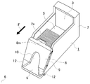
- FIG. 1A is a perspective view of a card shooter device according to Embodiment 1 of the present invention.
- FIG. 1B is a perspective view of the card shooter device with the top cover removed.
- FIG.1 (c) is a principal part expansion perspective view of the state which removed the top
- FIG. 1D is a perspective view of the card shooter device with the top cover and the front cover removed and the end of the top cover covered with the front of the main body of the card shooter device.
- FIG. 2 is an explanatory view of a procedure for opening and taking out the shuffle card from the packaging box and storing it in the card shooter device.
- FIG. 1A is a perspective view of a card shooter device according to Embodiment 1 of the present invention.
- FIG. 1B is a perspective view of the card shooter device with the top cover removed.
- FIG.1 (c) is a principal part expansion perspective view of the state which removed the top
- FIG. 3 is a perspective view of a front cover that is detachable from the card shooter device.
- FIG. 4 is a perspective view of an engaging member for attaching and detaching the front cover from the card shooter device.
- FIG. 5 is a schematic explanatory view showing an engaged state between the engaging member of the card shooter device and the hook receiving portion of the front cover.
- FIG. 6A is a schematic explanatory view showing a structure for locking the locking device for the engaging member of the card shooter device
- FIG. 6B is a locking device for the engaging member of the card shooter device. It is a schematic explanatory drawing which shows the structure which cancels
- FIG. 7A is a horizontal fracture view of the locking device for the engaging member of the card shooter device, and FIG.
- FIG. 7B is a vertical fracture of the locking device for the engagement member of the card shooter device.
- FIG. FIG. 8 is a perspective view of a state in which the side surface of the packaging box is removed and installed on the front portion of the bottom surface of the card shooter device.
- FIG. 9A is a perspective view of the card shooter device provided with an inclined extension body that is inclined from the tip of the bottom surface of the card shooter device and continues to the upper surface of the game table, and FIG. It is a side view.
- FIG. 10 is a plan view of the card.
- FIG. 11 is an enlarged perspective view of a main part in a state where the card reading device at the tip of the card shooter device is exposed.
- FIG. 12 is an enlarged perspective view of a main part in a state where the extension member is locked at the tip of the card shooter device.
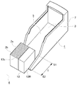
- FIGS. 1A, 1B, and 1C are perspective views of the card shooter device 1 according to Embodiment 1, and show different states.
- the card shooter device 1 includes a main body 7 including a card storage unit 3 that stores cards 2s constituting a predetermined number of decks, and a removable top cover that covers the card storage unit 3 at an upper portion of the card storage unit 3. 4 is arranged.
- the card storage unit 3 has a bottom surface 5 formed on the main body 7 that supports the cards 2 s stored in the card storage unit 3 and guides the cards 2 onto the game table 6 from the front.
- a front cover 8 is disposed in front of the main body 7 of the card shooter device 1 so that the cards can be taken out one by one from the card storage unit 3, and the front cover 8 is provided in front of the card shooter device 1.
- the front cover 8 is mounted in cooperation with the engaging member 9, the card 2s constituting the predetermined number of decks stored in the card storage unit 3 moves in the direction of the forward F arrow.
- an opening 10 through which the cards 2 can be passed one by one is formed on the bottom surface 5.
- the front cover 8 is removed, the cards 2s constituting a predetermined number of decks can be stored in the card storage unit 3.
- FIG. 1 (d) there is a protrusion 11 at the end on the back side of the top cover 4, which can be hooked on the locking member 12 of the card shooter device 1 and bridged.
- a slope that continues to the bottom surface 5 can be formed.
- the packaging box 13 has a rectangular parallelepiped shape, is provided with a cut line 13c parallel to the longitudinal direction of the rectangular parallelepiped, and divides the packaging box 13 along the cut line 13c so that the left or right side surface of the packaging box 13 is left.
- the card shooter device 1 includes a card storage unit 3 for storing cards 2s constituting a predetermined number of decks.
- a main body provided, a bottom surface 5 inclined forward to guide the card 2 from the card storage unit 3 onto the game table 6, and an engagement member 9 provided in front of the main body 7 to cooperate with the main body 7.
- a front cover 8 that is detachably mounted.
- top cover removal step (1) the top cover 4 disposed on the top of the card storage unit 3 of the card shooter device 1 is removed (top cover removal step), and (2) the main body 7 of the card shooter device 1 is removed.
- the front cover 8 is removed (front cover removal step), and (3) a packaging box 13 containing cards 2s constituting a predetermined number of decks is prepared, and the packaging box 13 is cut along the cut line 13c of the packaging box 13.
- the left or right side surface of the packaging box 13 is removed to expose the side surface of the card 2s in the packaging box 13 (card side surface exposure step, indicated by 2 in FIG. 2), (4) A cut card 14 is inserted into the card 2s in the packaging box 13 with the side surface exposed (card cut insertion step, indicated by 3 in FIG.
- the card 2s is slid together with a part of the packaging box 13 from the front of the main body 7 from which the front cover 8 is removed to the card storage unit 3 by using the bottom surface 5 as a guide (card 2s). 2 (indicated by 4 in FIG. 2), (6) The packaging box 13 is removed from the card storage unit 3 and only the card 2s is left in the card storage unit 3 (storage completion step. FIG. 2). , The card 2 s is stored in the card storage unit 3.
- the cut line of the packaging box 13 is not limited to one.
- the packaging box 13 provided with two cut lines can also be used.
- the other side surface is removed, and the card 2s may be accommodated in the card accommodating portion 3 in a state where the card 2s is held by the remaining central band-shaped portion, that is, in a state where both side surfaces of the card 2s are exposed. .
- an extension member 21 that forms a structure that bridges the upper surface of the game table 6 can be disposed at the front end of the card shooter device 1.
- the card 2 s can be slid from the upper surface of the extension member 21 together with a part of the packaging box 13 and stored in the card storage unit 3.
- This figure shows an example in which a structure that bridges the upper surface of the game table 6 is formed at the front end of the card shooter device 1 by using the top cover 4 as the extension member 21 (in FIG. 2, (Indicated by 1 and 4).
- the top cover 4 arranged on the upper part of the card storage unit 3 of the card shooter device 1 is removed, and the card 2 remains in the card storage unit 3 if this is left. Remove. Further, after the card 2s is stored in the card storage unit 3, the front cover 8 that has been removed from the main body is mounted on the card shooter device 1 (indicated by 5 in FIG. 2), and then the storage completion step ( 6) is performed.
- FIG. 4 two L-shaped hooks 15 are provided on the engaging member 9 fixed to the card shooter device 1 with bolts B.
- two L-shaped hook receiving portions 16 opposite to the above are provided on the back side of the front cover 8 where the engaging member 9 is attached.
- FIG. When the front cover 8 is slid from the upper side of the engaging member 9 to the diagonally downward arrow X, the two hooks 15 of the engaging member 9 and the two hook receiving portions 16 of the front cover 8 are engaged with each other.
- the engaging member 9 is provided with a groove 18 on the inner side of which the locking projection 17 is mounted.
- FIG. 7 On the back side of the front cover 8 where the engaging member 9 is mounted, FIG. As shown in FIG. 7, a button 20 having a bar-like button extension 19 is attached to the lower part (lock device).
- the front cover 8 is slid from the upper side of the engaging member 9 to the diagonally downward arrow X, the lower button extension 19 of the button 20 attached to the front cover 8 is inserted into the groove 18 of the engaging member 9. It enters and passes through the gap between the groove 18 and the locking projection 17 in the groove 18.
- the button extension 19 is caught by the locking projection 17 and cannot be returned (L state). Therefore, the button 20 at the top of the button extension 19 is pushed inward from the outside to the arrow Y and slid in the direction opposite to the arrow X, so that the button extension 19 moves inward in conjunction with the groove 18 and the groove. 18 can be returned to the original state (UL state) through a gap with the locking projection 17 in 18.
- the button 20 and the button extension 19 are connected to the front cover by a member having a structure of an elastic spring s. When the button 20 is pushed from the outside to the inside with a finger or the like and then released, the button 20 and the button extension 19 return to the original state.
- the front cover 8 must be slid in the diagonally upward direction (in the opposite direction of the arrow X) while pressing 20 to be removed.
- a magnet and an elastic spring s can also be used.
- the card shooter device 1 When the front cover 8 is mounted, the card shooter device 1 has a length l from the front cover lower side tip position 51 to the front end 52 of the main body on the bottom surface 5 that is more than half of the longitudinal direction of the packaging box 13 that stores the card 2s It is preferable that the length is configured as follows (see FIG. 8). If comprised in this way, the card
- the bottom surface 5 is It may be formed so as to be continuous with the upper surface of the game table 6 (see FIGS. 9A and 9B).
- the card 2s of the packaging box 13 with the side surface exposed is placed so as to straddle the game table 6 and the front end 52 of the main body, and then the card 2s is arranged from the front after the card 2s is aligned. It can be slid into the housing 3.
- the bottom surface 5 is continuous with the top surface of the game table 6 because the slant extension body 23 is within a range that does not hinder the sliding of the card 2 s to the card storage unit 3 between the bottom surface 5 and the game table 6. This includes the case where there is a step between the tip of the game table 6 and the game table 6.
- the tip 52 of the main body may be in contact with the game table 6.
- FIG. 10 shows the card 2 constituting the card 2s.
- a card 2 used in a table game such as a baccarat
- numbers are encoded and printed as a code C with UV ink or the like that is not normally visible.
- the code C is provided point-symmetrically on the upper side and the lower side of the card 2.
- the code C is preferably printed with a paint that is visualized by receiving ultraviolet light, and is printed at a position that does not overlap with the card type notation or index.
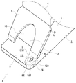
- the reading device 22 that reads the code C representing the number (rank, number, rank) of the card 2 from the card 2 when the card 2 is manually pulled out from the card housing 3 will be described with reference to FIG.
- the reading device 22 is provided on the bottom surface 5 that guides the cards 2 to be manually taken out one by one from the opening 10 in front of the card storage unit 3 onto the game table 6.
- the locking member 12 that also serves as the reading device cover 25 that covers the sensor group of the reading device 22 is removed, the sensor group of the reading device 22 is exposed (the reading device cover 25 is detachable with screws).
- the sensor group includes, for example, an ultraviolet reaction sensor (UV sensor) 120 and two object detection sensors 122 and 123.
- UV sensor ultraviolet reaction sensor
- the reading device 22 is controlled by a control unit (not shown) based on the detection signals of the object detection sensors 122 and 123 to start and end the reading of the UV sensor 120. Moreover, a control part (not shown) determines whether the card
- FIG. As shown in FIG. 10, quadrangular codes C representing the rank (number) and soot (heart, spade, etc.) of cards are arranged in two rows and four matrices on the edge of the card 2.
- the UV sensor 120 detects the code C, it outputs an ON signal.
- the reading device 22 identifies the code based on the relative difference between the two codes C detected by the UV sensor 120, and identifies the number (rank) and type (suit) of the corresponding card 2.
- the control device determines whether the game has been won or lost.
- the reading device cover 25 serves to protect the sensor group of the reading device 22 from being damaged, but the reading device cover 25 may be configured to function as the locking member 12.
- the card shooter device and the card storage method in the card storage portion of the card shooter device facilitates storing the card in the card storage portion of the card shooter device prior to the playing game, and the cards are scattered by mistake. It is possible to prevent a mistake that the deck is destroyed, and it is useful for a playing game such as a casino.
Abstract
Description
2 カード
2s 所定数のデッキを構成するカード
3 カード収納部
4 天面カバー
5 底面
6 ゲームテーブル
7 本体
8 フロントカバー
9 係合部材
10 開口部
11 突起
12 係止部材
13 包装箱
14 カットカード
15 フック
16 フック受け部
17 係止突起
18 溝
19 ボタン延長部
20 ボタン
21 延長部材
22 読取装置
23 傾斜延長体
24 ねじ
25 読取装置カバー
C コード
A マーク DESCRIPTION OF
Claims (15)
- 所定数のデッキを構成するカードを収納するカード収納部を備えた本体と
前記カード収納部の上部に配置され前記カード収納部を覆う着脱可能な天面カバーと、
前記カード収納部からカードをゲームテーブル上にガイドする前方に傾斜した底面と、
前記カード収納部からカードを一枚ずつ取り出すことができるよう前記本体の前方に配置されたフロントカバーと、
を備え、
前記フロントカバーは、前記本体の前方に設けられた係合部材と協働して前記本体から着脱可能に装着され、前記フロントカバー装着時には前記カード収納部に収納された所定数のデッキを構成するカードの前方方向の動きを制限すると共に、カードが一枚ずつ通過可能な開口部を前記底面との間に形成するとともに、前記フロントカバーを外した状態では前記底面をガイドにしてカードを前記本体の前方から前記カード収納部へ滑らせて入れることが可能な前面開口状態を構成する、シュータ装置。 A main body provided with a card storage unit for storing cards constituting a predetermined number of decks, and a removable top cover that is disposed on the card storage unit and covers the card storage unit;
A bottom surface inclined forward to guide the card from the card storage unit onto the game table;
A front cover disposed in front of the main body so that the cards can be taken out one by one from the card storage unit;
With
The front cover is detachably mounted from the main body in cooperation with an engaging member provided in front of the main body, and constitutes a predetermined number of decks stored in the card storage portion when the front cover is mounted. While restricting the movement of the card in the forward direction, an opening through which the cards can pass one by one is formed between the bottom and the card with the bottom as a guide when the front cover is removed. A shooter device that constitutes a front opening state that can be slid into the card storage portion from the front of the card. - 前記本体の先端前方に設けることが可能な延長部材をさらに有し、前記延長部材が、前記ゲームテーブル上面と前記底面との橋渡しをする、請求項1に記載のカードシュータ装置。 The card shooter device according to claim 1, further comprising an extension member that can be provided in front of the front end of the main body, wherein the extension member bridges the upper surface and the bottom surface of the game table.
- 前記延長部材を、前記カード収納部の上部に配置され前記カード収納部を覆う着脱可能な天面カバーにより構成することを特徴とする、請求項2に記載のカードシュータ装置。 3. The card shooter device according to claim 2, wherein the extending member is constituted by a detachable top cover that is disposed on an upper portion of the card storage portion and covers the card storage portion.
- 前記本体の先端に前記延長部材を係止する係止部材を設けた、請求項2または3に記載のカードシュータ装置。 The card shooter device according to claim 2 or 3, wherein a locking member for locking the extension member is provided at a tip of the main body.
- 前記天面カバーを前記本体の先端で係止するために、前記天面カバー下側に前記係止部材に係止される突起を設けた、請求項3または4に記載のカードシュータ装置。 The card shooter device according to claim 3 or 4, wherein a protrusion that is locked to the locking member is provided below the top surface cover in order to lock the top cover at the tip of the main body.
- 前記係止部材を、前記本体の先端に設けられた、前記カード収納部から一枚ずつ取り出されたカードを読み取る読取装置を覆う読取装置カバーにより構成することを特徴とする、請求項5に記載のカードシュータ装置。 The said locking member is comprised by the reader cover provided in the front-end | tip of the said main body which covers the reader which reads the card taken out from the said card | curd accommodating part one by one. Card shooter device.
- 前記底面の先端部から傾斜して前記ゲームテーブルの上面へ連続する傾斜延長体を備える、請求項1に記載のカードシュータ装置。 The card shooter device according to claim 1, further comprising an inclined extension body that inclines from the tip of the bottom surface and continues to the top surface of the game table.
- 前記傾斜延長体は前記本体から取り外すことができる、請求項1または7に記載のカードシュータ装置。 The card shooter device according to claim 1 or 7, wherein the inclined extension body can be detached from the main body.
- 前記フロントカバー装着時における、前記底面上の、前記フロントカバー下辺先端位置から、前記本体の先端までの長さが、前記カードを収納する包装箱の長手方向の半分以上の長さである、請求項1に記載のカードシュータ装置。 The length from the front cover lower edge tip position to the tip of the main body on the bottom surface when the front cover is mounted is more than half the length of the packaging box for storing the card. Item 2. The card shooter device according to Item 1.
- 所定数のデッキを構成するカードを収納する包装箱を用い、前記包装箱内のカードをゲームテーブルに配るためのカードシュータ装置に収納する方法であって、
前記包装箱は、直方体形状を有し、直方体の長手方向に平行にカット線を備え、前記カット線に沿って前記包装箱を分断して前記包装箱の左もしくは右側の側面を外すことにより前記包装箱内で前記カードの側面を露出することが可能な構成を備え、
前記カードシュータ装置は、所定数のデッキを構成するカードを収納するカード収納部を備えた本体と、前記カード収納部からカードをゲームテーブル上にガイドする前方に傾斜した底面と、
前記本体の前方に設けられ係合部材と協働して前記本体に着脱可能に装着されるフロントカバーとを備え、
前記方法は、
カードシュータ装置の前記カード収納部の上部に配置された天面カバーを取り外すステップ、
前記カードシュータ装置の前記本体から前記フロントカバーを取り外すステップ、
所定数のデッキを構成するカードを収納した包装箱を用意し、包装箱の前記カット線に沿って前記包装箱を分断して前記包装箱の左もしくは右側の側面を外して前記包装箱内のカードの側面を露出する側面露出ステップ、
側面を露出した状態の前記包装箱内のカードにカットカードを挿入するカードカットステップ、
前記カードを、前記包装箱の一部と共に、前記フロントカバーが取外された前記本体の前方から前記底面をガイドにしてカードを前記カード収納部へ滑らせて収納するカードの収納ステップ、
前記包装箱を前記カード収納部から取り除き、前記カードだけを前記カード収納部に残す、収納完了ステップ、を含むカードの収納方法。 A method of using a packaging box that stores cards constituting a predetermined number of decks, and storing the cards in the packaging box in a card shooter device for distributing to a game table,
The packaging box has a rectangular parallelepiped shape, includes a cut line parallel to the longitudinal direction of the rectangular parallelepiped, and divides the packaging box along the cut line to remove the left or right side surface of the packaging box. A configuration capable of exposing the side surface of the card in a packaging box,
The card shooter device includes a main body including a card storage unit that stores cards constituting a predetermined number of decks, a bottom surface that is inclined forward to guide a card from the card storage unit onto a game table,
A front cover provided in front of the main body and detachably attached to the main body in cooperation with an engaging member;
The method
Removing a top cover disposed on an upper portion of the card storage portion of the card shooter device;
Removing the front cover from the main body of the card shooter device;
Preparing a packaging box containing cards constituting a predetermined number of decks, dividing the packaging box along the cut line of the packaging box and removing the left or right side surface of the packaging box, Side exposure step to expose the side of the card,
A card cutting step of inserting a cut card into the card in the packaging box with the side surface exposed;
A card storing step for storing the card, together with a part of the packaging box, by sliding the card into the card storing section from the front of the main body from which the front cover is removed with the bottom surface as a guide,
A card storage method including a storage completion step of removing the packaging box from the card storage unit and leaving only the card in the card storage unit. - 前記本体の前方先端に延長部材を設け、延長部材の天面を前記カード収納部の底面と連続して形成させ、
前記側面を露出した状態の前記包装箱のカードを、前記延長部材上に置いた後、または前記延長部材と前記本体の先端にまたがるように置いた後、
前記カード収納部にカードを滑らせて収納する収納ステップをさらに含む、請求項10に記載のカードの収納方法。 An extension member is provided at the front end of the main body, and the top surface of the extension member is formed continuously with the bottom surface of the card storage unit,
After the card of the packaging box with the side surface exposed is placed on the extension member or after being placed across the extension member and the tip of the main body,
The card storing method according to claim 10, further comprising a storing step of sliding and storing the card in the card storing unit. - 前記延長部材として、前記カード収納部の上部に配置され前記カード収納部を覆う着脱可能な天面カバーを用いることを特徴とする、請求項11に記載のカードの収納方法。 12. The card storing method according to claim 11, wherein a detachable top cover that is disposed above the card storing part and covers the card storing part is used as the extension member.
- 前記本体の先端に設けられた延長部材を前記本体の先端で係止するステップをさらに含む請求項11または12に記載のカードの収納方法。 The card storing method according to claim 11 or 12, further comprising a step of locking an extension member provided at a front end of the main body at the front end of the main body.
- 前記係止するステップは、突起と前記突起で係止する係止部材を用いることを特徴とする、請求項13に記載のカードの収納方法。 The card storing method according to claim 13, wherein the locking step uses a protrusion and a locking member locked by the protrusion.
- 前記係止部材として、前記本体の先端に設けられた、前記カード収納部から一枚ずつ取り出されたカードを読み取る読取装置をカバーする読取装置カバー用いることを特徴とする、請求項14に記載のカードの収納方法。 15. The reading device cover according to claim 14, wherein a reading device cover that covers a reading device that is provided at a tip of the main body and that reads out cards one by one from the card storage portion is used as the locking member. How to store cards.
Priority Applications (23)
| Application Number | Priority Date | Filing Date | Title |
|---|---|---|---|
| KR1020207024319A KR20200103860A (en) | 2014-05-15 | 2015-05-15 | Card shooter device and card storage method |
| SG11201609573TA SG11201609573TA (en) | 2014-05-15 | 2015-05-15 | Card shooter device and card storage method |
| EP19180355.0A EP3560565B1 (en) | 2014-05-15 | 2015-05-15 | Card shooter device and card storage method |
| KR1020167031607A KR101897885B1 (en) | 2014-05-15 | 2015-05-15 | Card shooter device and card storage method |
| JP2016519123A JP6363183B2 (en) | 2014-05-15 | 2015-05-15 | Card shooter device and card storing method |
| ES15792414T ES2754244T3 (en) | 2014-05-15 | 2015-05-15 | Letter dispensing device and letter storage procedure |
| CN201580025328.1A CN106457035B (en) | 2014-05-15 | 2015-05-15 | Card shooter device and card storage method |
| CA2949196A CA2949196C (en) | 2014-05-15 | 2015-05-15 | Card shooter device and card storage method |
| AU2015260596A AU2015260596B2 (en) | 2014-05-15 | 2015-05-15 | Card shooter device and card storage method |
| US15/311,186 US10596449B2 (en) | 2014-05-15 | 2015-05-15 | Card shooter device and card storage method |
| NZ726266A NZ726266A (en) | 2014-05-15 | 2015-05-15 | Card shooter device and card storage method |
| KR1020217029393A KR20210118206A (en) | 2014-05-15 | 2015-05-15 | Card shooter device and card storage method |
| EP15792414.3A EP3132834B1 (en) | 2014-05-15 | 2015-05-15 | Card shooter device and card storage method |
| EP20203425.2A EP3791942A1 (en) | 2014-05-15 | 2015-05-15 | Card shooter device and card storage method |
| KR1020187025402A KR102150182B1 (en) | 2014-05-15 | 2015-05-15 | Card shooter device and card storage method |
| ZA2016/07883A ZA201607883B (en) | 2014-05-15 | 2016-11-15 | Card shooter device and card storage method |
| PH12016502279A PH12016502279B1 (en) | 2014-05-15 | 2016-11-15 | Card shooter device and card storage method |
| AU2018200712A AU2018200712B2 (en) | 2014-05-15 | 2018-01-30 | Card shooter device and card storage method |
| PH12018500644A PH12018500644A1 (en) | 2014-05-15 | 2018-03-22 | Card shooter device and card storage method |
| CY20191101000T CY1122228T1 (en) | 2014-05-15 | 2019-09-23 | CARD EJECT DEVICE AND CARD STORAGE METHOD |
| US16/787,773 US10888767B2 (en) | 2014-05-15 | 2020-02-11 | Card shooter device and card storage method |
| AU2020201080A AU2020201080B2 (en) | 2014-05-15 | 2020-02-14 | Card shooter device and card storage method |
| PH12020551296A PH12020551296A1 (en) | 2014-05-15 | 2020-08-20 | Card shooter device and card storage method |
Applications Claiming Priority (2)
| Application Number | Priority Date | Filing Date | Title |
|---|---|---|---|
| JP2014-115255 | 2014-05-15 | ||
| JP2014115255 | 2014-05-15 |
Related Child Applications (2)
| Application Number | Title | Priority Date | Filing Date |
|---|---|---|---|
| US15/311,186 A-371-Of-International US10596449B2 (en) | 2014-05-15 | 2015-05-15 | Card shooter device and card storage method |
| US16/787,773 Continuation US10888767B2 (en) | 2014-05-15 | 2020-02-11 | Card shooter device and card storage method |
Publications (1)
| Publication Number | Publication Date |
|---|---|
| WO2015174096A1 true WO2015174096A1 (en) | 2015-11-19 |
Family
ID=54479644
Family Applications (1)
| Application Number | Title | Priority Date | Filing Date |
|---|---|---|---|
| PCT/JP2015/002459 WO2015174096A1 (en) | 2014-05-15 | 2015-05-15 | Card shooter device and card storage method |
Country Status (15)
| Country | Link |
|---|---|
| US (2) | US10596449B2 (en) |
| EP (3) | EP3560565B1 (en) |
| JP (3) | JP6363183B2 (en) |
| KR (4) | KR101897885B1 (en) |
| CN (3) | CN106457035B (en) |
| AU (3) | AU2015260596B2 (en) |
| CA (2) | CA3058646C (en) |
| CY (1) | CY1122228T1 (en) |
| ES (2) | ES2754244T3 (en) |
| MY (2) | MY179081A (en) |
| NZ (2) | NZ741007A (en) |
| PH (3) | PH12016502279B1 (en) |
| SG (4) | SG11201609573TA (en) |
| WO (1) | WO2015174096A1 (en) |
| ZA (1) | ZA201607883B (en) |
Families Citing this family (1)
| Publication number | Priority date | Publication date | Assignee | Title |
|---|---|---|---|---|
| US10596449B2 (en) | 2014-05-15 | 2020-03-24 | Angel Playing Cards Co., Ltd. | Card shooter device and card storage method |
Citations (6)
| Publication number | Priority date | Publication date | Assignee | Title |
|---|---|---|---|---|
| US5669816A (en) * | 1995-06-29 | 1997-09-23 | Peripheral Dynamics, Inc. | Blackjack scanner apparatus and method |
| JP2003250950A (en) * | 2002-02-28 | 2003-09-09 | Danbonetto Systems Kk | Card housing box for distribution |
| US20050178784A1 (en) * | 2002-03-22 | 2005-08-18 | Wieslaw Waclawek | Card dispenser in particular for business and personal cards |
| US20090121429A1 (en) * | 2007-11-09 | 2009-05-14 | Shuffle Master, Inc. | Card delivery shoe and methods of fabricating the card delivery shoe |
| WO2012167004A2 (en) * | 2011-06-03 | 2012-12-06 | The United States Playing Card Company | Device to secure the mouth of a playing card shoe |
| JP2014031217A (en) * | 2012-08-05 | 2014-02-20 | Angel Playing Cards Co Ltd | Packaging box of shuffle playing card |
Family Cites Families (26)
| Publication number | Priority date | Publication date | Assignee | Title |
|---|---|---|---|---|
| US3706873A (en) * | 1969-07-31 | 1972-12-19 | John H Nodine | Digital data entry device |
| US4969648A (en) * | 1988-10-13 | 1990-11-13 | Peripheral Dynamics, Inc. | Apparatus and method for automatically shuffling cards |
| DE4439502C1 (en) * | 1994-11-08 | 1995-09-14 | Michail Order | Black jack card game practice set=up |
| US7699694B2 (en) * | 1995-10-17 | 2010-04-20 | Shuffle Master, Inc. | System including card game dispensing shoe and method |
| US5762203A (en) * | 1996-11-01 | 1998-06-09 | Goodmark Foods, Inc. | Container for shipping and displaying of product |
| USD432588S (en) * | 1999-08-30 | 2000-10-24 | Shuffle Master, Inc. | Card shuffling apparatus |
| US8262090B2 (en) * | 2001-12-13 | 2012-09-11 | The United States Playing Card Company | Method, apparatus and article for random sequence generation and playing card distribution |
| WO2004112923A1 (en) * | 2003-06-26 | 2004-12-29 | Tangam Gaming Technology Inc. | System, apparatus and method for automatically tracking a table game |
| US7769232B2 (en) * | 2003-07-17 | 2010-08-03 | Shuffle Master, Inc. | Unique sensing system and method for reading playing cards |
| CA2541377C (en) * | 2003-10-08 | 2017-03-21 | Arl, Inc. | Method, apparatus and article for computational sequence generation and playing card distribution |
| US6926149B2 (en) * | 2003-11-18 | 2005-08-09 | Kimberly-Clark Worldwide, Inc. | Compressed package having an opening mechanism and an expansion member |
| GB0403444D0 (en) | 2004-02-17 | 2004-03-24 | Goodwin Air Plasma Ltd | Earth connections for workpieces |
| US7866667B2 (en) * | 2005-11-29 | 2011-01-11 | Jerry Fruchtman | Card dispenser and storage and method for dispensing and storing cards |
| US7510186B2 (en) * | 2006-05-23 | 2009-03-31 | Bally Gaming, Inc. | Systems, methods and articles to facilitate delivery of playing cards |
| JP6091146B2 (en) | 2012-09-25 | 2017-03-08 | エンゼルプレイングカード株式会社 | Card shooter device and table game system |
| WO2009126780A2 (en) * | 2008-04-09 | 2009-10-15 | Walker Digital,Llc | System and method for card shoe security at a table game |
| JP2014003989A (en) * | 2010-10-18 | 2014-01-16 | Angel Playing Cards Co Ltd | Card reader and table game system |
| GB201020471D0 (en) * | 2010-12-03 | 2011-01-19 | Kyrychenko Olexandr I | Apparatus for handling playing cards and method of use |
| US9359106B2 (en) * | 2011-07-18 | 2016-06-07 | Westrock Mwv, Llc | Product dispensing system with multiple dispensing decks |
| US8960674B2 (en) * | 2012-07-27 | 2015-02-24 | Bally Gaming, Inc. | Batch card shuffling apparatuses including multi-card storage compartments, and related methods |
| AU2013203316B2 (en) * | 2012-09-25 | 2015-09-24 | Angel Group Co., Ltd. | Card shoe apparatus and table game system |
| CN104736209B (en) | 2012-10-18 | 2017-07-28 | 天使游戏纸牌股份有限公司 | Dealing out card device protector and table trip system |
| CA2893868A1 (en) * | 2012-12-19 | 2014-06-26 | Sca Hygiene Products Ab | Package comprising a stack of z-folded web material |
| RU2015150970A (en) * | 2013-04-29 | 2017-06-07 | Санофи Са | INHALED PHARMACEUTICAL COMPOSITIONS AND INHALER DEVICES FOR SUCH COMPOSITIONS |
| US10596449B2 (en) | 2014-05-15 | 2020-03-24 | Angel Playing Cards Co., Ltd. | Card shooter device and card storage method |
| US9566501B2 (en) * | 2014-08-01 | 2017-02-14 | Bally Gaming, Inc. | Hand-forming card shuffling apparatuses including multi-card storage compartments, and related methods |
-
2015
- 2015-05-15 US US15/311,186 patent/US10596449B2/en active Active
- 2015-05-15 MY MYPI2016002002A patent/MY179081A/en unknown
- 2015-05-15 SG SG11201609573TA patent/SG11201609573TA/en unknown
- 2015-05-15 EP EP19180355.0A patent/EP3560565B1/en active Active
- 2015-05-15 CN CN201580025328.1A patent/CN106457035B/en active Active
- 2015-05-15 EP EP15792414.3A patent/EP3132834B1/en active Active
- 2015-05-15 KR KR1020167031607A patent/KR101897885B1/en active IP Right Grant
- 2015-05-15 CN CN202010794569.5A patent/CN111821680A/en active Pending
- 2015-05-15 MY MYPI2018000498A patent/MY185011A/en unknown
- 2015-05-15 JP JP2016519123A patent/JP6363183B2/en active Active
- 2015-05-15 NZ NZ741007A patent/NZ741007A/en unknown
- 2015-05-15 SG SG10201802157RA patent/SG10201802157RA/en unknown
- 2015-05-15 CA CA3058646A patent/CA3058646C/en active Active
- 2015-05-15 ES ES15792414T patent/ES2754244T3/en active Active
- 2015-05-15 NZ NZ726266A patent/NZ726266A/en unknown
- 2015-05-15 KR KR1020217029393A patent/KR20210118206A/en not_active Application Discontinuation
- 2015-05-15 EP EP20203425.2A patent/EP3791942A1/en not_active Withdrawn
- 2015-05-15 CN CN202010794908.XA patent/CN111821681A/en active Pending
- 2015-05-15 SG SG10201913941TA patent/SG10201913941TA/en unknown
- 2015-05-15 AU AU2015260596A patent/AU2015260596B2/en active Active
- 2015-05-15 KR KR1020187025402A patent/KR102150182B1/en active IP Right Grant
- 2015-05-15 KR KR1020207024319A patent/KR20200103860A/en active Application Filing
- 2015-05-15 SG SG10201913943XA patent/SG10201913943XA/en unknown
- 2015-05-15 WO PCT/JP2015/002459 patent/WO2015174096A1/en active Application Filing
- 2015-05-15 CA CA2949196A patent/CA2949196C/en active Active
- 2015-05-15 ES ES19180355T patent/ES2859571T3/en active Active
-
2016
- 2016-11-15 PH PH12016502279A patent/PH12016502279B1/en unknown
- 2016-11-15 ZA ZA2016/07883A patent/ZA201607883B/en unknown
-
2018
- 2018-01-30 AU AU2018200712A patent/AU2018200712B2/en active Active
- 2018-03-22 PH PH12018500644A patent/PH12018500644A1/en unknown
- 2018-06-27 JP JP2018121504A patent/JP6694012B2/en active Active
-
2019
- 2019-09-23 CY CY20191101000T patent/CY1122228T1/en unknown
-
2020
- 2020-02-11 US US16/787,773 patent/US10888767B2/en active Active
- 2020-02-14 AU AU2020201080A patent/AU2020201080B2/en active Active
- 2020-04-16 JP JP2020073245A patent/JP2020142089A/en active Pending
- 2020-08-20 PH PH12020551296A patent/PH12020551296A1/en unknown
Patent Citations (6)
| Publication number | Priority date | Publication date | Assignee | Title |
|---|---|---|---|---|
| US5669816A (en) * | 1995-06-29 | 1997-09-23 | Peripheral Dynamics, Inc. | Blackjack scanner apparatus and method |
| JP2003250950A (en) * | 2002-02-28 | 2003-09-09 | Danbonetto Systems Kk | Card housing box for distribution |
| US20050178784A1 (en) * | 2002-03-22 | 2005-08-18 | Wieslaw Waclawek | Card dispenser in particular for business and personal cards |
| US20090121429A1 (en) * | 2007-11-09 | 2009-05-14 | Shuffle Master, Inc. | Card delivery shoe and methods of fabricating the card delivery shoe |
| WO2012167004A2 (en) * | 2011-06-03 | 2012-12-06 | The United States Playing Card Company | Device to secure the mouth of a playing card shoe |
| JP2014031217A (en) * | 2012-08-05 | 2014-02-20 | Angel Playing Cards Co Ltd | Packaging box of shuffle playing card |
Also Published As
Similar Documents
| Publication | Publication Date | Title |
|---|---|---|
| KR102105258B1 (en) | Method of inserting a cut card into a package of randomly shuffled playing cards | |
| KR101914401B1 (en) | Table game system | |
| JP6694012B2 (en) | Card shooter device and card storage method | |
| US20220370887A1 (en) | Disposal box for used playing cards |
Legal Events
| Date | Code | Title | Description |
|---|---|---|---|
| 121 | Ep: the epo has been informed by wipo that ep was designated in this application |
Ref document number: 15792414 Country of ref document: EP Kind code of ref document: A1 |
|
| ENP | Entry into the national phase |
Ref document number: 2016519123 Country of ref document: JP Kind code of ref document: A |
|
| ENP | Entry into the national phase |
Ref document number: 20167031607 Country of ref document: KR Kind code of ref document: A |
|
| REEP | Request for entry into the european phase |
Ref document number: 2015792414 Country of ref document: EP |
|
| WWE | Wipo information: entry into national phase |
Ref document number: 15311186 Country of ref document: US Ref document number: 2015792414 Country of ref document: EP |
|
| ENP | Entry into the national phase |
Ref document number: 2949196 Country of ref document: CA |
|
| NENP | Non-entry into the national phase |
Ref country code: DE |
|
| WWE | Wipo information: entry into national phase |
Ref document number: 12016502279 Country of ref document: PH |
|
| ENP | Entry into the national phase |
Ref document number: 2015260596 Country of ref document: AU Date of ref document: 20150515 Kind code of ref document: A |
|
| WWE | Wipo information: entry into national phase |
Ref document number: 12018500644 Country of ref document: PH |