CN106457035B - Card shooter device and card storage method - Google Patents
Card shooter device and card storage method Download PDFInfo
- Publication number
- CN106457035B CN106457035B CN201580025328.1A CN201580025328A CN106457035B CN 106457035 B CN106457035 B CN 106457035B CN 201580025328 A CN201580025328 A CN 201580025328A CN 106457035 B CN106457035 B CN 106457035B
- Authority
- CN
- China
- Prior art keywords
- card
- cards
- main body
- packing box
- card storage
- Prior art date
- Legal status (The legal status is an assumption and is not a legal conclusion. Google has not performed a legal analysis and makes no representation as to the accuracy of the status listed.)
- Active
Links
Images


Classifications
-
- A—HUMAN NECESSITIES
- A63—SPORTS; GAMES; AMUSEMENTS
- A63F—CARD, BOARD, OR ROULETTE GAMES; INDOOR GAMES USING SMALL MOVING PLAYING BODIES; VIDEO GAMES; GAMES NOT OTHERWISE PROVIDED FOR
- A63F1/00—Card games
- A63F1/06—Card games appurtenances
- A63F1/10—Card holders
-
- A—HUMAN NECESSITIES
- A63—SPORTS; GAMES; AMUSEMENTS
- A63F—CARD, BOARD, OR ROULETTE GAMES; INDOOR GAMES USING SMALL MOVING PLAYING BODIES; VIDEO GAMES; GAMES NOT OTHERWISE PROVIDED FOR
- A63F1/00—Card games
- A63F1/06—Card games appurtenances
- A63F1/14—Card dealers
Abstract
A card shooter device (1) is provided with: a main body (7) provided with a card storage unit (3), wherein the card storage unit (3) stores a predetermined number of cards (2 s); a detachable top cover (4) which is arranged on the upper part of the card accommodating part (3) and covers the card accommodating part (3); a bottom surface (5) which is inclined forward and guides the cards (2) from the card storage part (3) to the game table (6); and a front cover (8) that is disposed in front of the main body (7) so that the cards (2) can be taken out one by one from the card storage unit (3), wherein the front cover (8) is configured as follows: the card storage unit is detachably attached to the main body (7) in cooperation with an engaging member (9) provided in front of the main body (7), and can store a predetermined number of cards (2s) in the card storage unit (3) when the front cover (8) is removed.
Description
Technical Field
The present invention relates to a card shoe device used in a play game (playing game), and more particularly to a card shoe device and a card storage method capable of storing a playing card (hereinafter referred to as "card"), in particular, a predetermined number of decks of cards and a card packing box in which cards are stored, at a time without being lifted.
Background
In various entertainment games such as poker, baccarat, bridge, blackjack (Black Jack), and the like, a dealer (dealer) receives one or more decks of cards in a card dealing device, and draws out the cards one by one therefrom to deal them to game participants. When cards are stored in a card shooter, the following methods are widely used: in general, a dealer opens a top cover of an upper part of a card shoe device, and collectively picks up one or a plurality of decks of cards at a time to store the cards (see, for example, patent document 1).
Cards used in various entertainment games such as poker, baccarat, bridge, blackjack, and the like are used by storing 6 to 10 decks of cards in a card shooter. In the case of 8 decks, the deck is comprised of 416 cards, with a height of about 125 millimeters (mm). The shuffled cards forming the predetermined number of decks are cut while the cards are removed from the packing box or a part of the packing box is unsealed to expose the cards, and then the cut cards are stored in the card shooter. In order to play a game neatly, a dealer must keep a state in which only the back surface of a card is visible to a player until the card is unpacked from a packing box and stored in a card shoe device, and when the dealer stores the card in the card shoe device, the dealer must open a cover on the top surface of the card shoe device, and must also collectively hold the card by hand at one time without disturbing the structure of a whole deck of cards. On the other hand, the interval between the side portions of the card storage unit of the card shooter device is formed to be approximately the same size as the side of the cards so that the cards are not scattered therein and the arrangement order is not changed, and when 8 decks of cards are stored, there is a margin of about several centimeters in the depth direction. Therefore, when a dealer tries to take up and store a predetermined number of cards in a deck at a time, there is a problem that cards cannot be smoothly loaded. For example, there are problems as follows: the first deck of 8 decks of cards is hooked to the card shooter, and thus a mistake of carelessly scattering the cards and disturbing the entire deck of cards is likely to occur. Cards scattered on the game table cannot be used in the game, and therefore, the cards become a factor that hinders efficient progress of the game.
Documents of the prior art
Patent document
Patent document 1: international publication No. 2014/024239
Disclosure of Invention
The present invention has been accomplished in view of the above circumstances. The invention aims to provide a card dealing device and a method for containing cards, wherein the card dealing device comprises: the dealer can easily house cards in the card housing part of the card dealer before playing a game, and can prevent errors that the dealer carelessly scatters the cards to disorder the whole deck of cards.
One aspect of the present invention is a card shooter device including: a main body provided with a card storage unit that stores a predetermined number of cards; a detachable top cover disposed above the card storage unit and covering the card storage unit; a bottom surface inclined forward, which guides the cards to the game table from the card containing part; and a front cover arranged in front of the main body so as to be able to take out cards one by one from the card storage unit, the front cover having: the front cover is attached to the main body so as to be detachable from the main body in cooperation with an engaging member provided at the front of the main body, and is configured to restrict movement of a predetermined number of cards constituting a predetermined deck in the front direction when the front cover is attached, and is configured to form an opening portion between the front cover and the bottom surface through which the cards can pass one by one, and to form a front surface opening state in which the cards can be guided by the bottom surface so as to slide into the card storage portion from the front of the main body in a state where the front cover is detached.
Another aspect of the present invention is a card storage method for storing cards in a package box, the package box storing a predetermined number of cards, in a card dealing device for dealing the cards to a game table, the package box including: the card shooter device has a rectangular parallelepiped shape, includes a cutting line parallel to a longitudinal direction of the rectangular parallelepiped, and is configured to expose a side surface of the card in the packing box by detaching a left side surface or a right side surface of the packing box by cutting the packing box along the cutting line, and includes: a main body provided with a card storage unit that stores a predetermined number of cards; a bottom surface inclined forward, which guides the cards to the game table from the card containing part; and a front cover which is provided in front of the main body and is mounted to be detachable from the main body in cooperation with an engaging member, the method including: a step of removing a top cover disposed at an upper portion of the card storage section of the card shooter; detaching the front cover from the main body of the card shooter; a side surface exposure step of preparing a packing box containing a predetermined number of cards, and detaching a left side surface or a right side surface of the packing box by cutting the packing box along the cutting line of the packing box to expose the side surface of the cards in the packing box; a cut card insertion step of inserting a cut card into the card in the package box with the side surface exposed; a card storage step of guiding the card and the package box with the side surfaces removed from the front cover from the front of the main body at the bottom surface and storing the card in a sliding manner in the card storage portion; and a storage completion step of removing the packing box from the card storage unit and retaining only the cards in the card storage unit.
Effects of the invention
According to the present invention, it is easy to store cards in the card storage section of the card shooter before a game is played, and it is possible to prevent a mistake of carelessly scattering cards to shuffle a deck of cards, and to improve the work efficiency of the game in a casino.
As described below, other embodiments of the present invention exist. Accordingly, the disclosure of the present invention is intended to provide a part of the invention, and not to limit the scope of the invention described herein and claimed herein.
Drawings
Fig. 1(a) is a perspective view of a card shooter device according to embodiment 1 of the present invention.
Fig. 1(b) is a perspective view of the card shooter device in a state where the top cover is removed.
Fig. 1(c) is an enlarged perspective view of a main part of the card shooter device in a state where the top cover and the front cover are removed.
Fig. 1(d) is a perspective view of the card shooter device in a state where the top cover and the front cover are removed and an end of the top cover is locked to a front portion of a main body of the card shooter device.
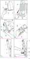
Fig. 2 is an explanatory diagram of a procedure for opening the packing box, taking out the shuffled playing cards, and storing the shuffled playing cards in the card shooter.
Fig. 3 is a perspective view of a front cover that can be attached to and detached from the card shoe apparatus.
Fig. 4 is a perspective view of an engaging member for attaching and detaching the front cover to and from the card shoe device.
Fig. 5 is a schematic explanatory diagram showing an engagement state of the engaging member of the card shoe device with the hook receiving portion of the front cover.
Fig. 6 (a) is a schematic explanatory view showing a structure in which a lock device of an engagement member of the card shoe device is in a locked state, and fig. 6 (b) is a schematic explanatory view showing a structure in which the lock device of the engagement member of the card shoe device is released.
Fig. 7 (a) is a horizontal cross-sectional view of the lock device of the engaging member of the card shoe device, and fig. 7 (b) is a vertical cross-sectional view of the lock device of the engaging member of the card shoe device.
Fig. 8 is a perspective view of the packing box removed from its side surface and installed in front of the bottom surface of the card shooter.
Fig. 9 (a) is a perspective view of a state where an inclined extension body that is inclined from the front end portion of the bottom surface of the card shoe device and continues to the upper surface of the game table is provided, and fig. 9 (b) is a partial side view of the state.
Figure 10 is a top view of a playing card.
Fig. 11 is a main part enlarged perspective view showing a state where the card reading device at the front end of the card shoe device is exposed.
Fig. 12 is a main-part enlarged perspective view showing a state where the extension member is locked to the front end of the card shoe device.
Detailed Description
The present invention will be described in detail below. The following detailed description and accompanying drawings do not limit the invention.
A method of storing the cards 2 in the packing box 13 in the card shooter 1 for dealing the cards to the game table 6 by using the packing box 13 for storing the cards 2s constituting a predetermined number of decks will be described with reference to fig. 2. The packing box 13 has the following structure: the card shooter device 1 has a rectangular parallelepiped shape, includes a cut line 13c parallel to a longitudinal direction of the rectangular parallelepiped, and is configured to expose a side surface of the card 2s in the packing box 13 by detaching a left side surface or a right side surface of the packing box 13 by cutting the packing box 13 along the cut line 13c, and includes: a main body provided with a card storage unit 3, the card storage unit 3 storing a predetermined number of cards 2 s; a bottom surface 5 inclined forward for guiding the card 2 from the card storage 3 to a game table 6; and a front cover 8 which is provided in front of the main body 7 and is detachably attached to the main body 7 in cooperation with an engaging member 9.
The method comprises the following steps: (1) removing a top cover 4 disposed on an upper portion of the card storage section 3 of the card shooter device 1 (top cover removing step); (2) removing the front cover 8 from the main body 7 of the card shoe apparatus 1 (front cover removing step); (3) preparing a packing box 13 in which a predetermined number of cards 2s are contained, and detaching a left side surface or a right side surface of the packing box 13 by cutting the packing box 13 along the cutting line 13c of the packing box 13 to expose the side surface of the card 2s in the packing box 13 (card side surface exposing step, indicated by 2 in fig. 2); (4) inserting a cut card 14 into the card 2s in the packing box 13 in a state of being exposed to the side surface (a cut card insertion step, indicated by 3 in fig. 2); (5) the card 2s and a part of the packing box 13 are guided through the bottom surface 5 from the front side of the main body 7 from which the front cover 8 is removed, and the card 2s is slid together with a part of the packing box 13 into the card storage section 3 and stored in the card storage section 3 (a card 2s storage step, indicated by 4 in fig. 2); (6) the packing box 13 is removed from the card storage unit 3, and only the card 2s is retained in the card storage unit 3 (a storage completion step, indicated by 6 in fig. 2), whereby the card 2s is stored in the card storage unit 3.
The cut line of the package 13 is not limited to one. For example, a package 13 having two cutting lines can be used. First, either the left or right side of the packing box 13 having the two cutting lines is removed, and the cut cards 14 are loaded (step (4)). Next, the other side surface may be removed, and the card 2s may be stored in the card storage unit 3 in a state where the card 2s is held by the remaining belt-shaped portion of the central portion, that is, in a state where both side surfaces of the card 2s are exposed.
As shown in fig. 1(d), an extension member 21 may be disposed at the front end of the front of the card shooter 1, and the extension member 21 may be bridged (overlapped) with the upper surface of the game table 6. The card 2s can be stored in the card storage unit 3 by sliding from the upper surface of the extension member 21 together with a part of the packing box 13. In the drawing, the following examples are shown as the extension member 21: a top cover 4 is provided at the front end of the front side of the card shooter 1 so as to bridge the upper surface of the game table 6 (indicated by reference numerals 1 and 4 in fig. 2).
As described above, in the embodiment of the present invention, the top cover 4 disposed above the card storage unit 3 of the card shooter device 1 is first removed, and the cards 2 are taken out when the cards 2 remain in the card storage unit 3. Further, after the cards 2s are stored in the card storage unit 3, the front cover 8 detached from the main body is attached to the card shooter 1 (indicated by 5 in fig. 2), and then the storage completion step (6) is performed.
Next, a detailed structure of the engaging member 9 for attaching and detaching the front cover 8 to and from the card shoe apparatus 1 will be described with reference to fig. 3 to 7 (b). As shown in fig. 4, two L-shaped hooks 15 are provided in the engaging member 9 fixed to the card shoe device 1 by bolts B. On the back side of the front cover 8 to which the engaging member 9 is attached, two L-shaped hook receiving portions 16 are provided in opposite directions, and as shown in fig. 5, when the front cover 8 is slid from above the engaging member 9 along an obliquely downward arrow X with the marks a of the two members aligned, the two hooks 15 of the engaging member 9 are engaged with the two hook receiving portions 16 of the front cover 8.
As shown in fig. 4, a groove 18 to which the locking projection 17 is attached is provided on the inner side of the engaging member 9, and a push button 20 (locking device) having a rod-like push button extension 19 is attached to the lower portion of the back side of the front cover 8 to which the engaging member 9 is attached, as shown in fig. 5 to 7. When the front cover 8 is slid from above the engaging member 9 so as to overlap the engaging member 9 along the obliquely downward arrow X, the button extension 19 attached to the lower portion of the button 20 of the front cover 8 enters the groove 18 of the engaging member 9, and advances through the gap between the groove 18 and the locking projection 17 in the groove 18. However, when the button extension portion 19 is engaged with the engaging projection 17 to return in the opposite direction after passing through the gap, the structure (L state) is made to be unable to return. Here, the push button 20 located above the push button extension 19 is pushed in from the outside to the inside along the arrow Y and is slid in the direction opposite to the arrow X, whereby the push button extension 19 can be moved inward in a linked manner, and the state can be restored (UL state) by passing through the gap between the groove 18 and the locking projection 17 in the groove 18. Here, the following structure is formed: the push button 20 and the push button extension 19 are connected to the front cover via a member having a structure of an elastic spring s, and when the push button 20 is pushed inward from the outside by a finger or the like and then released, the push button 20 is restored, and therefore, the front cover 8 must be detached by sliding obliquely upward (in the direction opposite to the arrow X) while pushing the push button 20. In addition to the engagement structure and the locking structure formed between the front cover 8 and the engaging member 9, a hook-shaped member, a magnet, and an elastic spring s can be used to enable the front cover 8 and the card shoe apparatus 1 to be attached and detached.
The card shooter device 1 is preferably configured to: when the front cover 8 is attached, the length l from the front cover lower edge front end position 51 to the front end 52 of the main body on the bottom surface 5 is equal to or more than half the length in the longitudinal direction of the packing box 13 in which the cards 2s are stored (see fig. 8). With this configuration, the cards 2s of the packing box 13 with the side surfaces exposed can be stably placed on the bottom surface 5 corresponding to the front end 52 of the main body from the front cover lower edge front end position 51 when the front cover 8 is attached, that is, the cards 2s can be prevented from being inclined toward the game table 6, and therefore, workability in aligning the arrangement of the cards 2s is improved.
Further, the inclined extension body 23 having a tip end contacting the game table 6 may be separately provided at the tip end 52 of the main body, and the bottom surface 5 may be formed to be continuous with the upper surface of the game table 6 by contacting the tip end of the inclined extension body 23 with the game table 6 (see fig. 9 a and 9 b). With this configuration, after the cards 2s of the packing box 13 with the side surfaces exposed are placed so as to straddle the game table 6 and the front end 52 of the main body, the arrangement of the cards 2s can be aligned and then slid into the card accommodation portion 3 from the front of the main body 7. Here, the continuation of the bottom surface 5 with the upper surface of the game table 6 also includes the following cases: in a range where there is no obstacle when the card 2s is slid toward the card storage section 3 between the bottom surface 5 and the game table 6, there is a step between the tip of the inclined extension body 23 and the game table 6. Here, instead of using the inclined extension 23, the front end 52 of the main body may be brought into contact with the game table 6. With this configuration, the restriction on the place where the cards 2s are placed is relaxed, and therefore, the workability in aligning the cards 2s is improved.
Fig. 10 shows cards 2 constituting a card 2 s. In the card 2 used in a table game such as baccarat, a number is coded and printed as a code C using UV ink or the like which is not normally visible to the naked eye. The code C is arranged point-symmetrically on the upper and lower sides of the card 2. The code C is preferably printed with paint that is visible by exposure to ultraviolet light and is printed at a position that does not overlap the indicia or index of the card type.
Next, the details of the reading device 22 that reads the code C indicating the number (digit, number, rank) of the card 2 from the card 2 when the card 2 is manually drawn from the card housing unit 3 will be described with reference to fig. 11. The reading device 22 is provided on the bottom surface 5 that guides the cards 2 manually taken out one by one from the opening 10 in front of the card storage 3 onto the game table 6. When the locking member 12 serving also as the reader cover 25 is removed, the sensor group of the reader 22 is exposed (the reader cover 25 can be removed by a screw), and the reader cover 25 covers the sensor group of the reader 22. The sensor group includes, for example, an ultraviolet-ray reaction sensor (UV sensor) 120 and two object detection sensors 122 and 123.
The start and end of reading by the UV sensor 120 of the reading device 22 are controlled by a control unit (not shown) based on detection signals of the object detection sensors 122 and 123. The control unit (not shown) determines whether the card 2 has normally passed through the bottom surface 5 based on the detection signals of the object detection sensors 122 and 123. As shown in fig. 10, a code C indicating the rank (number) and suit (e.g., a red peach or a black peach) of the card is arranged in 2 rows and 4 columns at the edge of the card 2. The UV sensor 120 outputs an on signal after detecting the code C. In the reading device 22, the relative relationship of the two signals input from the UV sensor 120 is determined. Thus, the reading device 22 identifies the code from the relative difference between the two codes C detected by the UV sensor 120, and identifies the number (rank) and the type (suit) of the corresponding card 2.
In this way, the win or loss of the game is determined by a control device (not shown) based on the number (rank) of the cards 2 read from the cards 2.
The reader cover 25 functions to protect the sensor group of the reader 22 from damage, and the reader cover 25 may be configured to function as the locking member 12.
While there have been described what are at present considered to be the preferred embodiments of the invention, it will be understood that various modifications can be made thereto, and it is intended that the appended claims cover all such modifications as fall within the true spirit and scope of the invention.
Industrial applicability
The card shooter device and the method for storing cards in the card storage unit of the card shooter device according to the present invention are useful for a game of entertainment in a casino or the like, because it is easy to store cards in the card storage unit of the card shooter device before the game of entertainment, and it is possible to prevent a mistake of carelessly scattering cards to shuffle a whole deck of cards.
Description of the reference numerals
Card dealing device
2 playing card
2s constituting a predetermined number of decks of cards
3 card storage part
4 top cover
5 bottom surface
6 Game table
7 main body
8 front cover
9 engaging member
10 opening part
11 protrusion
12 locking part
13 packing box
14 cutting board (cut card)
15 hook
16 hook receiving portion
17 locking projection
18 groove
19 button extension
20 push button
21 extension part
22 reading device
23 inclined extension body
24 screw
25 reading device cover
C code
Symbol A
Claims (11)
1. A card dealing device, in which,
the disclosed device is provided with:
a main body provided with a card storage unit that stores a predetermined number of cards;
a detachable top cover disposed above the card storage unit and covering the card storage unit;
a bottom surface inclined forward, which guides the cards from the card containing part to the game table; and
a front cover arranged in front of the main body so that cards can be taken out one by one from the card storage unit,
the front cover is attached to the main body so as to be detachable from the main body in cooperation with an engaging member provided in front of the main body, and restricts movement of a predetermined number of cards contained in the card containing section in a forward direction when the front cover is attached, and an opening section through which the cards can pass one by one is formed between the front cover and the bottom surface, and a front surface opening state in which the cards can be guided on the bottom surface so as to slide in from front of the main body to the card containing section in a state where the front cover is detached is configured,
further comprising an extension member positionable forward of the front end of the body, the extension member bridging the gaming table upper surface with the bottom surface,
the extension member is constituted by a detachable top cover,
a locking member for locking the extension member is provided at the front end of the body,
in order to lock the top cover to the front end of the main body, a protrusion to be locked with the locking member is provided on the lower side of the top cover.
2. The card-handing apparatus of claim 1, wherein,
the locking member is configured by a reading device cover covering a reading device which is provided at a front end of the main body and reads cards taken out one by one from the card storage section.
3. The card-handing apparatus of claim 1, wherein,
the game table is provided with an inclined extension body which is inclined from the front end part of the bottom surface and is continuous to the upper surface of the game table.
4. The card-handing apparatus of claim 3, wherein,
the inclined extension body is detachable from the main body.
5. The card-handing apparatus of claim 1, wherein,
the length from a lower front end position of the front cover on the bottom surface to a front end of the main body when the front cover is attached is equal to or more than half of a length of a packing box in a longitudinal direction of the packing box for storing the cards.
6. A card storage method for storing cards in a packing box in a card dealing device for dealing the cards to a game table, the packing box storing a predetermined number of cards, wherein,
the packing box has the following structure: a rectangular parallelepiped shape having a cutting line parallel to the longitudinal direction of the rectangular parallelepiped, wherein the side surface of the card can be exposed in the package by detaching the left or right side surface of the package by breaking the package along the cutting line,
the card shooter device is provided with: a main body provided with a card storage unit that stores a predetermined number of cards; a bottom surface inclined forward, which guides the cards from the card containing part to the game table; and a front cover which is arranged in front of the main body and is installed to be matched with the clamping component and can be detached relative to the main body,
the method comprises the following steps:
removing a top cover disposed at an upper portion of the card storage unit of the card shooter device;
a step of detaching the front cover from the main body of the card shoe;
a side surface exposure step of preparing a packing box containing a predetermined number of cards, and detaching a left side surface or a right side surface of the packing box by cutting the packing box along the cutting line of the packing box to expose the side surface of the cards in the packing box;
a cut card insertion step of inserting a cut card into a card in the packing box in a state where a side surface is exposed;
a card storage step of guiding the card and a part of the packing box from the front side of the main body after the front cover is removed at the bottom surface and storing the card in a sliding manner in the card storage part; and
and a storage completion step of removing the packing box from the card storage unit and retaining only the cards in the card storage unit.
7. The card housing method according to claim 6,
an extension member is provided at a front end of the main body such that a top surface of the extension member is formed continuously with a bottom surface of the card storage section,
further, the method includes a storage step of storing the cards in the packing box with the side surfaces exposed by sliding the cards into the card storage portion after placing the cards on the extension member or after placing the cards across the extension member and the front end of the main body.
8. The card housing method according to claim 7,
as the extension member, a detachable top cover is used, and the top cover is disposed above the card storage section and covers the card storage section.
9. The card housing method according to claim 7 or 8,
further comprising a locking step of locking an extension member provided at the front end of the main body to the front end of the main body.
10. The card housing method according to claim 9,
in the locking step, a protrusion and a locking member locked to the protrusion are used.
11. The card housing method according to claim 10,
as the locking member, a reading device cover that covers a reading device that is provided at the front end of the main body and reads cards taken out one by one from the card storage unit is used.
Priority Applications (2)
| Application Number | Priority Date | Filing Date | Title |
|---|---|---|---|
| CN202010794908.XA CN111821681A (en) | 2014-05-15 | 2015-05-15 | Card shooter device and card storage method |
| CN202010794569.5A CN111821680A (en) | 2014-05-15 | 2015-05-15 | Card shooter device and card storage method |
Applications Claiming Priority (3)
| Application Number | Priority Date | Filing Date | Title |
|---|---|---|---|
| JP2014-115255 | 2014-05-15 | ||
| JP2014115255 | 2014-05-15 | ||
| PCT/JP2015/002459 WO2015174096A1 (en) | 2014-05-15 | 2015-05-15 | Card shooter device and card storage method |
Related Child Applications (2)
| Application Number | Title | Priority Date | Filing Date |
|---|---|---|---|
| CN202010794569.5A Division CN111821680A (en) | 2014-05-15 | 2015-05-15 | Card shooter device and card storage method |
| CN202010794908.XA Division CN111821681A (en) | 2014-05-15 | 2015-05-15 | Card shooter device and card storage method |
Publications (2)
| Publication Number | Publication Date |
|---|---|
| CN106457035A CN106457035A (en) | 2017-02-22 |
| CN106457035B true CN106457035B (en) | 2020-09-08 |
Family
ID=54479644
Family Applications (3)
| Application Number | Title | Priority Date | Filing Date |
|---|---|---|---|
| CN201580025328.1A Active CN106457035B (en) | 2014-05-15 | 2015-05-15 | Card shooter device and card storage method |
| CN202010794569.5A Pending CN111821680A (en) | 2014-05-15 | 2015-05-15 | Card shooter device and card storage method |
| CN202010794908.XA Pending CN111821681A (en) | 2014-05-15 | 2015-05-15 | Card shooter device and card storage method |
Family Applications After (2)
| Application Number | Title | Priority Date | Filing Date |
|---|---|---|---|
| CN202010794569.5A Pending CN111821680A (en) | 2014-05-15 | 2015-05-15 | Card shooter device and card storage method |
| CN202010794908.XA Pending CN111821681A (en) | 2014-05-15 | 2015-05-15 | Card shooter device and card storage method |
Country Status (15)
| Country | Link |
|---|---|
| US (2) | US10596449B2 (en) |
| EP (3) | EP3560565B1 (en) |
| JP (3) | JP6363183B2 (en) |
| KR (4) | KR101897885B1 (en) |
| CN (3) | CN106457035B (en) |
| AU (3) | AU2015260596B2 (en) |
| CA (2) | CA3058646C (en) |
| CY (1) | CY1122228T1 (en) |
| ES (2) | ES2754244T3 (en) |
| MY (2) | MY179081A (en) |
| NZ (2) | NZ741007A (en) |
| PH (3) | PH12016502279B1 (en) |
| SG (4) | SG11201609573TA (en) |
| WO (1) | WO2015174096A1 (en) |
| ZA (1) | ZA201607883B (en) |
Families Citing this family (1)
| Publication number | Priority date | Publication date | Assignee | Title |
|---|---|---|---|---|
| US10596449B2 (en) | 2014-05-15 | 2020-03-24 | Angel Playing Cards Co., Ltd. | Card shooter device and card storage method |
Citations (1)
| Publication number | Priority date | Publication date | Assignee | Title |
|---|---|---|---|---|
| CN103052428A (en) * | 2010-10-18 | 2013-04-17 | 天使游戏纸牌股份有限公司 | Card reader device and tabletop game system |
Family Cites Families (31)
| Publication number | Priority date | Publication date | Assignee | Title |
|---|---|---|---|---|
| US3706873A (en) * | 1969-07-31 | 1972-12-19 | John H Nodine | Digital data entry device |
| US4969648A (en) * | 1988-10-13 | 1990-11-13 | Peripheral Dynamics, Inc. | Apparatus and method for automatically shuffling cards |
| DE4439502C1 (en) * | 1994-11-08 | 1995-09-14 | Michail Order | Black jack card game practice set=up |
| US5669816A (en) * | 1995-06-29 | 1997-09-23 | Peripheral Dynamics, Inc. | Blackjack scanner apparatus and method |
| US7699694B2 (en) * | 1995-10-17 | 2010-04-20 | Shuffle Master, Inc. | System including card game dispensing shoe and method |
| US5762203A (en) * | 1996-11-01 | 1998-06-09 | Goodmark Foods, Inc. | Container for shipping and displaying of product |
| USD432588S (en) * | 1999-08-30 | 2000-10-24 | Shuffle Master, Inc. | Card shuffling apparatus |
| US8262090B2 (en) * | 2001-12-13 | 2012-09-11 | The United States Playing Card Company | Method, apparatus and article for random sequence generation and playing card distribution |
| JP2003250950A (en) * | 2002-02-28 | 2003-09-09 | Danbonetto Systems Kk | Card housing box for distribution |
| PL352958A1 (en) * | 2002-03-22 | 2003-10-06 | Wiesław Wacławek | Appliance for issuing cards, particularly business cards |
| WO2004112923A1 (en) * | 2003-06-26 | 2004-12-29 | Tangam Gaming Technology Inc. | System, apparatus and method for automatically tracking a table game |
| US7769232B2 (en) * | 2003-07-17 | 2010-08-03 | Shuffle Master, Inc. | Unique sensing system and method for reading playing cards |
| CA2541377C (en) * | 2003-10-08 | 2017-03-21 | Arl, Inc. | Method, apparatus and article for computational sequence generation and playing card distribution |
| US6926149B2 (en) * | 2003-11-18 | 2005-08-09 | Kimberly-Clark Worldwide, Inc. | Compressed package having an opening mechanism and an expansion member |
| GB0403444D0 (en) | 2004-02-17 | 2004-03-24 | Goodwin Air Plasma Ltd | Earth connections for workpieces |
| US7866667B2 (en) * | 2005-11-29 | 2011-01-11 | Jerry Fruchtman | Card dispenser and storage and method for dispensing and storing cards |
| US20090121429A1 (en) * | 2007-11-09 | 2009-05-14 | Shuffle Master, Inc. | Card delivery shoe and methods of fabricating the card delivery shoe |
| US7510186B2 (en) * | 2006-05-23 | 2009-03-31 | Bally Gaming, Inc. | Systems, methods and articles to facilitate delivery of playing cards |
| JP6091146B2 (en) | 2012-09-25 | 2017-03-08 | エンゼルプレイングカード株式会社 | Card shooter device and table game system |
| WO2009126780A2 (en) * | 2008-04-09 | 2009-10-15 | Walker Digital,Llc | System and method for card shoe security at a table game |
| GB201020471D0 (en) * | 2010-12-03 | 2011-01-19 | Kyrychenko Olexandr I | Apparatus for handling playing cards and method of use |
| CN103619426B (en) * | 2011-06-03 | 2016-10-12 | 美国扑克牌公司 | The equipment of the mahjong pieces outlet of stationary game card type dealing box |
| US9359106B2 (en) * | 2011-07-18 | 2016-06-07 | Westrock Mwv, Llc | Product dispensing system with multiple dispensing decks |
| US8960674B2 (en) * | 2012-07-27 | 2015-02-24 | Bally Gaming, Inc. | Batch card shuffling apparatuses including multi-card storage compartments, and related methods |
| JP6157074B2 (en) | 2012-08-05 | 2017-07-05 | エンゼルプレイングカード株式会社 | Shuffle playing card packaging box |
| AU2013203316B2 (en) * | 2012-09-25 | 2015-09-24 | Angel Group Co., Ltd. | Card shoe apparatus and table game system |
| CN104736209B (en) | 2012-10-18 | 2017-07-28 | 天使游戏纸牌股份有限公司 | Dealing out card device protector and table trip system |
| CA2893868A1 (en) * | 2012-12-19 | 2014-06-26 | Sca Hygiene Products Ab | Package comprising a stack of z-folded web material |
| RU2015150970A (en) * | 2013-04-29 | 2017-06-07 | Санофи Са | INHALED PHARMACEUTICAL COMPOSITIONS AND INHALER DEVICES FOR SUCH COMPOSITIONS |
| US10596449B2 (en) | 2014-05-15 | 2020-03-24 | Angel Playing Cards Co., Ltd. | Card shooter device and card storage method |
| US9566501B2 (en) * | 2014-08-01 | 2017-02-14 | Bally Gaming, Inc. | Hand-forming card shuffling apparatuses including multi-card storage compartments, and related methods |
-
2015
- 2015-05-15 US US15/311,186 patent/US10596449B2/en active Active
- 2015-05-15 MY MYPI2016002002A patent/MY179081A/en unknown
- 2015-05-15 SG SG11201609573TA patent/SG11201609573TA/en unknown
- 2015-05-15 EP EP19180355.0A patent/EP3560565B1/en active Active
- 2015-05-15 CN CN201580025328.1A patent/CN106457035B/en active Active
- 2015-05-15 EP EP15792414.3A patent/EP3132834B1/en active Active
- 2015-05-15 KR KR1020167031607A patent/KR101897885B1/en active IP Right Grant
- 2015-05-15 CN CN202010794569.5A patent/CN111821680A/en active Pending
- 2015-05-15 MY MYPI2018000498A patent/MY185011A/en unknown
- 2015-05-15 JP JP2016519123A patent/JP6363183B2/en active Active
- 2015-05-15 NZ NZ741007A patent/NZ741007A/en unknown
- 2015-05-15 SG SG10201802157RA patent/SG10201802157RA/en unknown
- 2015-05-15 CA CA3058646A patent/CA3058646C/en active Active
- 2015-05-15 ES ES15792414T patent/ES2754244T3/en active Active
- 2015-05-15 NZ NZ726266A patent/NZ726266A/en unknown
- 2015-05-15 KR KR1020217029393A patent/KR20210118206A/en not_active Application Discontinuation
- 2015-05-15 EP EP20203425.2A patent/EP3791942A1/en not_active Withdrawn
- 2015-05-15 CN CN202010794908.XA patent/CN111821681A/en active Pending
- 2015-05-15 SG SG10201913941TA patent/SG10201913941TA/en unknown
- 2015-05-15 AU AU2015260596A patent/AU2015260596B2/en active Active
- 2015-05-15 KR KR1020187025402A patent/KR102150182B1/en active IP Right Grant
- 2015-05-15 KR KR1020207024319A patent/KR20200103860A/en active Application Filing
- 2015-05-15 SG SG10201913943XA patent/SG10201913943XA/en unknown
- 2015-05-15 WO PCT/JP2015/002459 patent/WO2015174096A1/en active Application Filing
- 2015-05-15 CA CA2949196A patent/CA2949196C/en active Active
- 2015-05-15 ES ES19180355T patent/ES2859571T3/en active Active
-
2016
- 2016-11-15 PH PH12016502279A patent/PH12016502279B1/en unknown
- 2016-11-15 ZA ZA2016/07883A patent/ZA201607883B/en unknown
-
2018
- 2018-01-30 AU AU2018200712A patent/AU2018200712B2/en active Active
- 2018-03-22 PH PH12018500644A patent/PH12018500644A1/en unknown
- 2018-06-27 JP JP2018121504A patent/JP6694012B2/en active Active
-
2019
- 2019-09-23 CY CY20191101000T patent/CY1122228T1/en unknown
-
2020
- 2020-02-11 US US16/787,773 patent/US10888767B2/en active Active
- 2020-02-14 AU AU2020201080A patent/AU2020201080B2/en active Active
- 2020-04-16 JP JP2020073245A patent/JP2020142089A/en active Pending
- 2020-08-20 PH PH12020551296A patent/PH12020551296A1/en unknown
Patent Citations (1)
| Publication number | Priority date | Publication date | Assignee | Title |
|---|---|---|---|---|
| CN103052428A (en) * | 2010-10-18 | 2013-04-17 | 天使游戏纸牌股份有限公司 | Card reader device and tabletop game system |
Also Published As
Similar Documents
| Publication | Publication Date | Title |
|---|---|---|
| KR101914401B1 (en) | Table game system | |
| KR101929152B1 (en) | Table game system | |
| CN106457035B (en) | Card shooter device and card storage method |
Legal Events
| Date | Code | Title | Description |
|---|---|---|---|
| C06 | Publication | ||
| PB01 | Publication | ||
| C10 | Entry into substantive examination | ||
| SE01 | Entry into force of request for substantive examination | ||
| REG | Reference to a national code |
Ref country code: HK Ref legal event code: DE Ref document number: 1232486 Country of ref document: HK |
|
| GR01 | Patent grant | ||
| GR01 | Patent grant | ||
| CP01 | Change in the name or title of a patent holder | ||
| CP01 | Change in the name or title of a patent holder |
Address after: Shiga Patentee after: Angel Group Co.,Ltd. Address before: Shiga Patentee before: ANGEL PLAYING CARDS Co.,Ltd. |