WO2015172744A1 - Grass cutting machine and pay-off method for grass cutting machine - Google Patents
Grass cutting machine and pay-off method for grass cutting machine Download PDFInfo
- Publication number
- WO2015172744A1 WO2015172744A1 PCT/CN2015/079128 CN2015079128W WO2015172744A1 WO 2015172744 A1 WO2015172744 A1 WO 2015172744A1 CN 2015079128 W CN2015079128 W CN 2015079128W WO 2015172744 A1 WO2015172744 A1 WO 2015172744A1
- Authority
- WO
- WIPO (PCT)
- Prior art keywords
- reel
- extension rod
- slider
- receiving seat
- switch
- Prior art date
Links
Images


Classifications
-
- A—HUMAN NECESSITIES
- A01—AGRICULTURE; FORESTRY; ANIMAL HUSBANDRY; HUNTING; TRAPPING; FISHING
- A01D—HARVESTING; MOWING
- A01D34/00—Mowers; Mowing apparatus of harvesters
- A01D34/01—Mowers; Mowing apparatus of harvesters characterised by features relating to the type of cutting apparatus
- A01D34/412—Mowers; Mowing apparatus of harvesters characterised by features relating to the type of cutting apparatus having rotating cutters
- A01D34/416—Flexible line cutters
Definitions
- the invention relates to a garden tool, in particular to a grass cutter.
- Green vegetation is an essential environmental element for our human beings, and the awareness of greening is becoming more and more popular. Whether it is a golf course, a football field, a manor, a villa's courtyard, or an ordinary residential community, green turf is everywhere, bringing vitality and vitality to people's lives. But if you leave people's care, these turf will become ups and downs and chaos.
- the lawnmower generally drives the grass by rotating the grass, usually including an extension rod extending longitudinally, a grass head provided at one end of the extension rod, a handle disposed on the extension rod and spaced apart from the grass head. And driving the grass for rotating the grass head, the grass head comprises a receiving seat, a cover matched with the receiving seat, a wire disc disposed between the receiving seat and the cover, and the grassing wire is wound on the wire tray and protrudes from the receiving seat. When working, the grass head is driven to rotate to drive the grass line to rotate synchronously to fight grass.
- the lawnmower usually has two states of use, one of which is a conventional grassing state. At this time, the plane formed by the rotation of the grass line is parallel to the ground plane, and is used for quickly handling the large lawn; Another use state is the trimming state. At this time, the plane formed by the rotation of the grass line is perpendicular to the ground plane, and is used to take care of the lawn at the edge of the road.
- a wire-removing mechanism is required on the lawn mower to adjust the length of the grass-line extending from the receptacle at an appropriate time.
- the switch-off mechanism will automatically release the line every time it is turned on and off, no additional operation is required, but it is because of each time. Both the power on and off will be put on the line, and the loss of the grass line is more serious.
- the other is a tapping and paying mechanism.
- the tapping and paying mechanism has a triggering member protruding from the cover. When the cover is used, the cover is struck on the ground to trigger the triggering of the triggering device.
- the main disadvantage is that the trimming operation is performed on the lawnmower. At that time, it is necessary to reverse the lawn mower so that the lid can strike the ground to release the line, not only to interrupt the trimming and grassing work but also to be cumbersome to operate.
- an operating member independent of the main switch is disposed in the grip portion, and the movement of the operating member is transmitted to the reel through the transmission connecting member, so that the speed difference between the reel and the receiving seat is released.
- this manual pay-off mechanism requires a transmission member that extends substantially through the longitudinally extending extension rod to be able to handle the hand. The movement of the moving member is transmitted to the reel. Therefore, the telescopic type or the disassembled type is provided with respect to the extended extension rod, and the installation structure of the transmission member is complicated, and the reliability is not guaranteed.
- Another type of pay-off mechanism includes an operating member for operation by an operator, a wire rope controlled by the operating member and movably disposed on the extension rod, and a driving device for driving the reel to release the grass line by the wire rope.
- the operator can realize the manual threading of the reel by operating the operating member, but in order to satisfy the operation comfort, the extension rod is usually made long, which greatly increases the packaging volume of the lawnmower, which is not only inconvenient to transport, but also improved. The cost of transportation.
- the problem to be solved by the present invention is to provide a lawn mower that reduces the loss of grass lines and is easy to operate.
- a lawnmower comprising a longitudinally extending extension rod, a casing disposed at one end of the extension rod, and being disposed on the extension rod and the casing a handle disposed at a distance, a grass head connected to the casing, a main motor that drives the grass head to rotate about an axis, and a main switch that controls the main motor, the grass head includes a receiving seat, and a cover that is mated by the receiving seat, a wire reel disposed between the receiving seat and the cover, the wire reel having a first state that is relatively stationary with the receiving seat, wherein the grass mower further includes a pay-off mechanism, the pay-off mechanism comprising a pay-off electronic switch independent of the main switch, and a control device, the pay-off electronic switch operatively electrically controlling the control device to enable the reel to be capable of receiving A second state of difference in rotational speed is generated between the seats.
- the operating speed of the main motor during operation is constant.
- control device comprises an electric drive independent of the main motor, the pay-off mechanism comprising a transmission driven by an electric drive, the electric drive driving the reel in the first state and the Movement between the two states.
- the electric drive includes a secondary motor that is independent of the main motor.
- the transmission device includes a motion conversion mechanism disposed between the secondary motor and the reel, and the motion conversion mechanism converts the rotational motion of the secondary motor into a rotational motion of the reel relative to the housing to generate a speed difference.
- the motion conversion mechanism includes a transmission member fixedly coupled to an output shaft of the secondary motor, a pivoting member driven by the transmission member, and an intermediate member driven by the pivoting member, the intermediate member driving the reel to move relative to the receiving seat .
- the transmission member is disposed to be fixedly coupled to the eccentric cam of the output shaft, and the pivoting member is disposed as a lever centered on the pivot axis, wherein the pivot shaft fixedly connects the first end of the lever to the casing, the lever The second end abuts the peripheral surface of the eccentric cam.
- the transmission member is disposed to be fixedly coupled to the end surface cam of the output shaft, and the pivoting member is disposed as a lever centered on the pivot axis, wherein the pivot shaft fixedly connects the first end of the lever In the casing, the second end of the lever abuts against the cam surface of the end cam.
- an elastic member is disposed between the pivoting member and the casing.
- the transmission further includes a speed reduction mechanism disposed between the secondary motor and the transmission member.
- the speed reduction mechanism is provided as a planetary gear mechanism.
- the control device also includes a stop device that controls the secondary motor to stop rotating.
- the stopping device includes a sensing unit, and a control unit that receives the signal of the sensing unit and stops the control of the secondary motor.
- the sensing element comprises a Hall sensor disposed on the casing, and a magnetic member disposed on the transmission, the Hall sensor being disposed adjacent to the magnetic member.
- the motor shaft of the secondary motor is disposed perpendicular to the motor shaft of the main motor.
- the motor shaft of the secondary motor is arranged parallel to the motor shaft of the main motor.
- the electric drive comprises an electromagnet.
- the electromagnet has an output for linear motion, and the transmission includes a third drive train disposed between the output end and the spool.
- the third drive train includes a rotating member pivotally coupled to the casing, and a sliding member driven by the rotating member, the sliding member driving the reel to move relative to the receiving seat.
- the rotating member is disposed as a lever centered on the pivoting shaft, wherein the pivoting shaft is disposed at a middle portion of the lever, the first end of the lever is coupled to the output end, and the second end of the lever abuts the sliding member.
- the payoff electronic switch controls energization and de-energization of the electromagnet.
- control device includes a control circuit electrically coupled to the main motor for controlling the main motor to switch between a normal operating speed and a payout speed.
- the control circuit is a PWM modulation circuit.
- the payoff speed is less than the working speed.
- control circuit is a brake switch circuit.
- the payout speed is greater than the working speed.
- the reel when the main switch is activated, the reel is in a first state, and when the pay-off electronic switch is activated, the reel is in a second state.
- a slider is disposed between the receiving seat and the wire reel, and the slider is fixedly coupled to the receiving seat in a radial direction, and the wire releasing mechanism further comprises an activity.
- a stopping device of the receiving seat the stopping device has a first position and a second position, and when the stopping device is in the first position, The stopping device limits radial movement of the slider relative to the receiving seat, and the slider is radially movable relative to the receiving seat when the stopping device is in the second position.
- the stopping device comprises a stopping member pivoted on the receiving seat. In the first position, the stopping member stops the sliding block, and in the second position, the stopping member and the stopping member The slider is disengaged.
- the stopper is pivoted from the first position to the second position relative to the receiving seat by the inertial force.
- the stop is pivoted from the second position to the first position.
- the stopping means comprises a resetting means provided between the stop and the receiving seat, the resetting means causing the stop to return from the second position to the first position.
- the pivot axis of the stop overlaps the axis of rotation of the receptacle.
- the stopper when the main switch is activated, the stopper is in a first position that restricts radial movement of the slider relative to the receiving seat.
- the reel is provided with a circumferentially extending toothed groove
- the toothed groove includes a first toothed edge and a second toothed edge which are oppositely disposed, the first toothed edge and the first The number of teeth on the second toothed edge is the same and circumferentially staggered
- the tooth includes a radially extending radial face
- the slider is provided with protruding teeth that are radially movable within the toothed groove.
- the tooth comprises a circumferentially obliquely extending circumferential surface
- the wire reel is in the second state when the protruding tooth abuts the circumferential surface.
- a biasing member is disposed between the receiving seat and the slider, and the biasing member urges the slider to keep the protruding teeth abutting the radial surface.
- the reel moves circumferentially along the axis.
- the spool moves axially along the axis.
- the main switch is electrically connected to the control device.
- the pay-off electronic switch is disposed adjacent to the grip or grip of the handle.
- the handle includes a main handle and an auxiliary handle disposed at a certain distance.
- the main switch is disposed on the main handle, and the pay-off electronic switch is disposed on the auxiliary handle.
- the pay-off electronic switch is a single-pole double-throw switch, and the single-pole double-throw switch is selectively in a first closed position and a second closed position, and the main switch is activated to rotate the reel and the receiving seat synchronously.
- the single-pole double-throw switch is in the first closed position; the single-pole double-throw switch is activated, and the single-pole double-throw switch is switched from the first closed position to the second closed position, so that a speed difference is generated between the coil and the receiving seat;
- the throwing switch returns the single-pole double-throw switch from the second closed position to the first closed position, so that a speed difference is generated between the reel and the receiving seat, and after the preset time, the reel and the receiving seat resume synchronous rotation.
- the invention is also realized by a pay-off method of a grass-carrying machine, and the pay-off method comprises the following steps: starting the pay-off electronic switch to generate a speed difference between the wire reel and the receiving seat.
- the operating step further comprises releasing the payoff electronic switch.
- the main switch is activated to cause the main motor to drive the receiving seat to rotate synchronously with the reel.
- Another method for releasing the line includes the following steps: starting the main switch to rotate the reel and the receiving seat synchronously; starting the electronic switch to make a speed difference between the reel and the receiving seat, after a preset time, the reel Resynchronous rotation with the housing.
- a lawnmower comprising a longitudinally extending extension rod, a casing disposed at one end of the extension rod, and being disposed on the extension rod and a handle disposed at a distance from the casing, a grass head connected to the casing, a main motor that drives the grass head to rotate about an axis, and a main switch that controls the main motor, the grass head includes a receiving a seat, a cover that is coupled to the receiving seat, and a wire disc disposed between the receiving seat and the cover, the wire reel having a first state that is relatively stationary with the receiving seat, wherein the grass is
- the machine further includes a pay-off mechanism including a pay-off electronic switch independent of the main switch, and a control device, the pay-off electronic switch operatively electrically controlling the control device to enable the reel In a second state in which a rotational speed difference is generated between the housing and the housing, the running speed of the main motor during operation is constant.
- the operating speed of the main motor during operation is constant.
- control device comprises an electric drive independent of the main motor, the pay-off mechanism comprising a transmission driven by an electric drive, the electric drive driving the reel in the first state and the Movement between the two states.
- the electric drive includes a secondary motor that is independent of the main motor.
- the transmission device includes a motion conversion mechanism disposed between the secondary motor and the reel, and the motion conversion mechanism converts the rotational motion of the secondary motor into a rotational motion of the reel relative to the housing to generate a speed difference.
- the motion conversion mechanism includes a transmission member fixedly coupled to an output shaft of the secondary motor, a pivoting member driven by the transmission member, and an intermediate member driven by the pivoting member, the intermediate member driving the reel to move relative to the receiving seat .
- the transmission member is disposed to be fixedly coupled to the eccentric cam of the output shaft, and the pivoting member is configured to A lever having a pivot axis as a center of rotation, wherein the pivot shaft fixedly connects the first end of the lever to the casing, and the second end of the lever abuts against a peripheral surface of the eccentric cam.
- the transmission member is disposed to be fixedly coupled to the end surface cam of the output shaft, and the pivoting member is disposed as a lever centered on the pivot axis, wherein the pivot shaft fixedly connects the first end of the lever In the casing, the second end of the lever abuts against the cam surface of the end cam.
- an elastic member is disposed between the pivoting member and the casing.
- the transmission further includes a speed reduction mechanism disposed between the secondary motor and the transmission member.
- the speed reduction mechanism is provided as a planetary gear mechanism.
- the control device also includes a stop device that controls the secondary motor to stop rotating.
- the stopping device includes a sensing unit, and a control unit that receives the signal of the sensing unit and stops the control of the secondary motor.
- the sensing element comprises a Hall sensor disposed on the casing, and a magnetic member disposed on the transmission, the Hall sensor being disposed adjacent to the magnetic member.
- the motor shaft of the secondary motor is disposed perpendicular to the motor shaft of the main motor.
- the motor shaft of the secondary motor is arranged parallel to the motor shaft of the main motor.
- the electric drive comprises an electromagnet.
- the electromagnet has an output for linear motion, and the transmission includes a third drive train disposed between the output end and the spool.
- the third drive train includes a rotating member pivotally coupled to the casing, and a sliding member driven by the rotating member, the sliding member driving the reel to move relative to the receiving seat.
- the rotating member is disposed as a lever centered on the pivoting shaft, wherein the pivoting shaft is disposed at a middle portion of the lever, the first end of the lever is coupled to the output end, and the second end of the lever abuts the sliding member.
- the payoff electronic switch controls energization and de-energization of the electromagnet.
- a lawnmower comprising a longitudinally extending extension rod, a casing disposed at one end of the extension rod, and being disposed on the extension rod and a handle disposed at a distance from the casing, a grass head connected to the casing, a main motor that drives the grass head to rotate about an axis, and a main switch that controls the main motor;
- the grass head includes a receiving body a seat, a cover coupled to the receiving seat, a reel disposed between the receiving seat and the cover, the reel having a first state relatively stationary with the receiving seat;
- the lawnmower Also included is a payout mechanism including a control switch and a control device, the control switch operatively electrically controlling the control device to cause the spool to be in a rotational speed difference between the receptacle and the receptacle Two states.
- control device includes a control circuit electrically coupled to the main motor for controlling the main motor to transition between a normal operating speed and a payout speed.
- control circuit is a PWM modulation circuit.
- the payoff speed is less than the operating speed.
- control circuit is a brake switch circuit.
- control switch is the main switch or a payoff electronic switch that is independent of the main switch.
- a method for paying off a lawnmower includes the following steps: starting a control switch to generate a speed difference between the wire reel and the receiving seat.
- the operating step further includes releasing the control switch.
- the main motor drives the housing to rotate synchronously with the reel.
- a method for paying a grass-carrying machine includes the following steps: starting the main switch to rotate the wire disc and the receiving seat synchronously; and starting the control switch, A speed difference is generated between the reel and the accommodating seat. After the preset time, the reel and the accommodating seat resume synchronous rotation.
- a method for paying off a lawnmower the control switch is a pay-off electronic switch independent of the main switch, and the pay-off electronic switch is a single knife
- the double throw switch, the single pole double throw switch is selectively in a first closed position and a second closed position
- the payoff method comprises the following steps: starting the main switch to rotate the reel and the receiving seat synchronously, and the single pole double throw The switch is in the first closed position; the discharge electronic switch is activated, and the single-pole double-throw switch is switched from the first closed position to the second closed position, so that a speed difference is generated between the wire reel and the receiving seat; the discharge electronic switch is released, and the single-knife is released
- the double throw switch returns from the second closed position to the first closed position, and the reel and the receiving seat resume to rotate synchronously.
- a method for paying a lawnmower the control switch is a main switch, the main switch is a single pole double throw switch, and the single pole double throw switch is selectable a first closed position and a second closed position
- the pay-off method comprising the steps of: activating the main switch to rotate the reel synchronously with the receiving seat, wherein the main switch is in the first closed position; and the single-pole double-throw switch is from the first Closed position conversion value second closed position, causing a speed difference between the reel and the receiving seat; restarting the main switch, returning the single-pole double-throw switch from the second closed position to the first closed position, and the reel and the receiving seat are restored Rotate.
- the lawn mower of the present invention comprises a pay-off mechanism, and the pay-off mechanism is controlled by a pay-off electronic switch independent of the main switch, thereby avoiding waste of paying off each time the switch is turned off, thereby reducing grassing The loss of the wire; and the pay-off electronic switch is disposed in the vicinity of the grip portion or the grip portion of the handle, and the operator can control the pay-off electronic switch while holding the handle to release the line without interrupting the lawnmower. Work and easy to operate.
- the first technical problem to be solved by the present invention is to provide a lawn mower that not only reduces the loss of the grass line but also has a small package volume.
- the first technical solution of the present invention is:
- a lawn mower comprising an extension rod assembly, a grass head disposed at one end of the extension rod assembly, a handle disposed on the extension rod assembly and spaced apart from the grass head, and driving the hit A motor that rotates around the axis of rotation controls the switch of the motor.
- the grass head includes a wire reel for setting a grassing line
- the grass mower further includes a manual pay-off mechanism
- the manual pay-off mechanism includes an operation member independent of the switch, and is controlled by the operation member a transmission member, a driving device driven by the transmission member to drive the reel to release the grassing line
- the extension rod assembly comprising a longitudinally extending first extension rod and a movable connection to the first extension rod a second extension rod, the handle is disposed on the first extension rod, the grass head is disposed on the second extension rod, and the first and second extension rods are each provided with an inner cavity, the transmission The pieces are disposed substantially in the inner cavity of the first and second extension rods.
- the lawn mower of the present invention comprises a manual pay-off mechanism, and the manual pay-off mechanism is controlled by an operation member independent of the switch setting, thereby avoiding waste of paying off each time the switch machine is off, thereby reducing grass clipping.
- the loss of the wire; and the extension rod assembly is configured as a first and a second extension rod that are movably coupled to each other to cause relative movement between the first and second extension rods when transporting or storing the lawnmower, thereby greatly reducing the amount of movement The packaging volume of the grass machine.
- the first and second extension rods have a first position that is mated with each other and a second position that is disengaged from each other.
- a threaded connection is adopted between the first and second extension rods.
- the first extension rod is provided with an electrode piece
- the second extension rod is provided with an electric wire
- the electrode piece is electrically connected to the electric wire when the first extension rod is mated with the second extension rod.
- the transmission member includes a first transmission portion coupled to the operating member and a second transmission portion movably disposed relative to the first transmission portion, the second transmission portion being coupled to the driving device.
- the first transmission portion and the second transmission portion are coupled to each other, and when the first extension rod and the second extension rod are disengaged from each other, The first transmission The portion and the second transmission portion are disengaged from each other.
- the manual pay-off mechanism further includes a mating device disposed between the first transmission portion and the second transmission portion, the mating device including the first extension rod and the a connector connected to the first transmission portion, a sliding member disposed in the second extension rod and connected to the second transmission portion, the sliding member being engageable or disengageable from the adapter member.
- the mating device further includes an actuating device disposed on the first extension rod for engaging the mating member with the sliding member, thereby connecting the first transmission portion and the second transmission portion Together, the operating member is operated to drive the second transmission portion to move toward the operating member through the first transmission portion to drive the driving device to drive the reel to release the grassing line.
- an actuating device disposed on the first extension rod for engaging the mating member with the sliding member, thereby connecting the first transmission portion and the second transmission portion
- the operating member is operated to drive the second transmission portion to move toward the operating member through the first transmission portion to drive the driving device to drive the reel to release the grassing line.
- the actuating device comprises an annular seat fixedly disposed in the first extension rod, the annular seat body comprising a first portion and a second portion having an inner diameter smaller than the first portion, the mating
- the member is operatively movable from a first position to a second position in a direction of extending the first extension rod toward the operating member, the adapter being disengaged from the slider when in the first position
- the second portion urges the mating member to mate with the slider.
- the mating device further includes a first elastic member disposed between the adapter and the first extension rod for causing the adapter to be disengaged from the slider.
- the mating device further includes a slider movably disposed on the annular seat body, the first transmission portion is coupled to the slider, and the adapter member is pivotally disposed on the slider Block, the first elastic member is disposed between the adapter and the slider.
- the mating device further comprises a tensioning device disposed between the slider and the annular seat for urging the slider to move away from the operating member.
- the tensioning device comprises a second elastic member disposed between the annular seat and the slider.
- the actuating device comprises an actuating member movably disposed on the first extending rod and abutting the mating member, and a pushing member disposed on the second extending rod, the first extending rod The pusher urges the actuating member to move when mated with the second extension rod, the actuating member causing the mating member to mate with the slider.
- the actuating member is coupled to the first extension rod and the first extension rod and the second extension rod are mated to each other.
- the actuating member is movably coupled to the first extension rod.
- the moving direction of the actuating member is perpendicular to the extending direction of the first extension rod.
- the mating device further comprises a gap between the adapter and the first extension rod for A retaining device that urges the adapter to disengage from the slider.
- the retaining device comprises an elastic unit.
- the elastic unit is a torsion spring.
- the mating device further comprises a tensioning device disposed between the adapter and the first extension rod for causing the adapter to move away from the operating member.
- the tensioning device comprises a resilient element.
- the elastic element is provided as a compression spring, and the compression spring is arranged along a longitudinal extension direction of the first extension rod.
- the adapter is pivotable relative to the first extension rod.
- the first extension rod is telescopic with respect to the second extension rod.
- the manual pay-off mechanism further includes a pulley assembly disposed in the extension rod assembly, and the transmission member is disposed on the pulley assembly.
- the pulley assembly includes a fixed pulley fixed to the first extension rod and a movable pulley connected to the operation member and operatively movable along an extending direction of the first extension rod, the movable pulley Closer to the operating member than the fixed pulley, the transmission member is sleeved on the outer edge of the fixed pulley and the movable pulley, the transmission member includes a fixed end fixedly coupled to the second extension rod and connected to the The movable end of the driving device, and the fixed end is located between the fixed pulley and the movable pulley.
- the diameter of the fixed pulley is smaller than the diameter of the movable pulley.
- one of the tangents of the outer edge between the fixed pulley and the movable pulley is parallel to the extending direction of the first extension rod.
- the manual pay-off mechanism further includes a reset device disposed between the movable pulley and the first extension rod for resetting the movable pulley.
- the resetting device comprises a second compression spring.
- the transmission member is a flexible transmission shaft.
- a second technical problem to be solved by the present invention is to provide a simple and convenient method of using a lawnmower.
- the second technical solution of the present invention is:
- a method of using a lawnmower comprising: a longitudinally extending first extension rod and a second extension rod movably coupled to the first extension rod, a handle disposed on the first extension rod, a grass head disposed at an end of the second extension rod away from the first extension rod, a motor driving the grass head to rotate about the rotation axis, and a switch for controlling the motor, the grass head including a grass for setting Line reel, said hit
- the grass machine further includes a manual pay-off mechanism, the manual pay-off mechanism comprising an operating member independent of the switch, a transmission member controlled by the operating member and disposed in the inner cavity of the first and second extension rods,
- the driving member drives the driving device for driving the wire reel to release the grassing line
- the using method comprises the steps of: fitting the first extension rod and the second extension rod to operate the operation member,
- the transmission member drives the driving device to drive the wire reel to release the grassing line.
- the lawnmower of the present invention can operate the operating member by fitting the first extension rod and the second extension rod, so that the transmission member drives the driving device to drive the reel to release the grassing line. Therefore, the operation is very simple and convenient.
- the transmission member includes a first transmission portion and a second transmission portion movably coupled to the first transmission portion, the method of use further comprising the steps of: arranging the first extension rod and the second extension rod After that, the operating member is operated to pull the first transmission portion to connect the first transmission portion and the second transmission portion together.
- the transmission member includes a first transmission portion and a second transmission portion movably coupled to the first transmission portion, the method of use further comprising the steps of: arranging the first extension rod and the second extension rod After that, the first transmission portion and the second transmission portion are coupled together.
- the first extension rod is provided with an electrode piece
- the second extension rod is provided with an electric wire
- the electrode piece is electrically connected to the electric wire when the first extension rod is mated with the second extension rod.
- FIG. 1 is a schematic cross-sectional view of a whole machine of a lawnmower according to a first embodiment of the present invention.
- Figure 2 is an enlarged cross-sectional view of the head of the lawnmower shown in Figure 1, in which the lever is in the rest position.
- Figure 3 is an enlarged cross-sectional view of the head of the lawnmower shown in Figure 1, at which time the lever drives the spool to move.
- Fig. 4 is a perspective exploded view showing the thread take-up mechanism of the head of the lawnmower shown in Fig. 1.
- FIG. 9 are schematic diagrams showing the state change process of the slider and the reel in the process of controlling the pay-off of the pay-off mechanism shown in FIG.
- Figure 10 is an enlarged schematic view showing the relative position of the Hall element in the head of the lawnmower and the magnetic member on the transmission member along the line A-A of Figure 2, in which case the Hall element is adjacent to the magnetic member.
- Figure 11 is an enlarged schematic view showing the relative position of the Hall element in the head of the lawnmower and the magnetic member on the transmission member along the line B-B of Figure 3, in which case the Hall element is offset from the magnetic member by 180 degrees.
- FIG. 12 is a schematic flow chart of the take-up mechanism of FIG. 1 controlling the wire take-up line.
- Figure 13 is an enlarged cross-sectional view showing the head of the lawnmower according to the second embodiment of the present invention.
- Figure 14 is an enlarged cross-sectional view showing the head of the lawnmower of the third embodiment of the present invention.
- Figure 15 is a view showing the mating relationship between the lever and the slider shown in section C-C of Figure 14;
- FIG. 16 to FIG. 20 are schematic diagrams showing a state change process of the reel and the receiving seat and the cover during the process of controlling the pay-off of the pay-off mechanism shown in FIG. 14;
- 21 to 23 are views showing the operation of the control circuit of the lawnmower according to the fourth and fifth embodiments of the present invention.
- Fig. 24 is a view showing the change of the rotational speed of the main motor of the lawnmower according to the fourth embodiment of the present invention.
- Figure 25 is a view showing the change of the rotational speed of the main motor of the lawnmower according to the fifth embodiment of the present invention.
- Figure 26 is a flow chart showing the operation of the lawnliner's take-up control in the fourth and fifth embodiments of the present invention.
- 27 to 29 are views showing the operation of the control circuit of the lawnmower according to the sixth embodiment of the present invention.
- Fig. 30 is a view showing the change of the rotational speed of the main motor of the lawnmower according to the sixth embodiment of the present invention.
- Figure 31 is an enlarged cross-sectional view showing the head of a lawnmower according to a seventh embodiment of the present invention.
- Fig. 32 is a perspective exploded view showing the thread take-up mechanism of the head of the lawnmower shown in Fig. 31;
- FIG. 35 are schematic diagrams showing the state change process of the slider and the stopper device during the process of controlling the payout of the pay-off mechanism shown in FIG.
- Figure 36 is a perspective exploded view showing the thread take-up mechanism in the head of the lawnmower according to the eighth embodiment of the present invention.
- 37 to 39 are schematic views showing the state change process of the slider and the stopper device during the process of controlling the pay-off of the lawn-lifting mechanism of the lawnmower shown in FIG.
- 40 to 41 are schematic views showing the operation of a control circuit of a lawn mower according to a ninth embodiment of the present invention.
- Figure 42 is a view showing the change of the rotational speed of the main motor of the lawnmower according to the ninth embodiment of the present invention.
- Figure 43 is a perspective view of the lawnmower of the tenth embodiment of the present invention with the one side of the grass head removed;
- Figure 44 is a cross-sectional view showing the whole machine of the lawnmower according to the tenth embodiment of the present invention.
- Figure 45 is an enlarged schematic view showing the joint of the first and second extension rods of the lawnmower shown in Figure 44, wherein the first extension rod and the second extension rod are disengaged, and the first transmission portion and the second transmission portion are disengaged;
- Figure 46 is an enlarged schematic view showing the joint of the first and second extension rods of the lawnmower shown in Figure 44. At this time, the first extension rod cooperates with the second extension rod, and the first transmission portion is in a non-pull free state, first The transmission portion is disconnected from the second transmission portion;
- Figure 47 is an enlarged schematic view showing the joint of the first and second extension rods of the lawnmower shown in Figure 44, in which the first extension rod cooperates with the second extension rod, the first transmission portion is in the pulled state, and the second transmission portion No motion is generated, and the first transmission portion is mated with the second transmission portion;
- Figure 48 is an enlarged schematic view showing the connection of the first and second extension rods of the lawnmower shown in Figure 44.
- the first extension rod cooperates with the second extension rod, the first transmission portion is coupled with the second transmission portion, the first transmission portion is in the pulled state, and the second transmission portion is moved relative to the second extension rod by a certain distance to perform the payout ;
- Figure 49 is an enlarged cross-sectional view showing the joint of the first and second extension rods of the lawnmower according to the eleventh embodiment of the present invention, in which the first extension rod and the second extension rod are disengaged, the first transmission portion and the second transmission portion Disengage
- Figure 50 is an enlarged cross-sectional view showing the joint of the first and second extension rods of the lawnmower according to the eleventh embodiment of the present invention. At this time, the first extension rod cooperates with the second extension rod portion, and the actuator is not pushed. a transmission portion is disconnected from the second transmission portion;
- Figure 51 is an enlarged cross-sectional view showing the joint of the first and second extension rods of the lawnmower according to the eleventh embodiment of the present invention, in which the first extension rod and the second extension rod are completely mated, and the actuator is pushed, a transmission portion is coupled to the second transmission portion, and the first transmission portion is in a non-pull free state;
- Figure 52 is an enlarged cross-sectional view showing the joint of the first and second extension rods of the lawnmower according to the eleventh embodiment of the present invention, in which the first extension rod and the second extension rod are completely mated, the first transmission portion and the second portion The transmission portion is mated, the first transmission portion is in a pulled state, and the second transmission portion is moved a certain distance relative to the second extension rod to perform a payout;
- Figure 53 is an enlarged cross-sectional view showing the junction of the first and second extension rods of the lawnmower according to the twelfth embodiment of the present invention, wherein the second extension rod is in an extended position with respect to the first extension rod, and the movable pulley is in a free state;
- Figure 54 is an enlarged cross-sectional view showing the junction of the first and second extension rods of the lawnmower according to the twelfth embodiment of the present invention, wherein the second extension rod is in a retracted position with respect to the first extension rod, and the movable pulley is in a free state;
- Figure 55 is an enlarged cross-sectional view showing the junction of the first and second extension rods of the lawnmower according to the twelfth embodiment of the present invention, wherein the second extension rod is in a retracted position relative to the first extension rod, and the movable pulley is in a pulled state.
- the transmission member is driven to move a certain distance relative to the second extension rod to perform the payout.
- connection end 1060, first adapter 1114, connection end
- FIG. 1 to 12 show a lawnmower 100 according to a first embodiment of the present invention.
- the lawn mower 100 of the present embodiment includes an extension rod 20 extending longitudinally and a head disposed at one end of the extension rod 20 .
- the head includes a casing 25 , a main motor 26 disposed in the casing 25 , And a grass head 22 driven by the main motor 26 to rotate about an axis; the grass cutter 100 further includes a handle disposed on the extension rod 20 and spaced apart from the casing 25, and a main switch 27 for controlling the main motor.
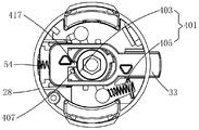
- the grass head 22 includes a receiving seat 28, a cover 30 that is coupled to the receiving seat 28, and a reel 32 that is disposed in the inner cavity formed by the receiving seat 28 and the cover 30.
- the spool 32 has a first state that is relatively stationary with the receptacle 28. When the main switch 27 controls the rotation of the main motor 26, the reel 32 rotates in synchronization with the housing 28 in the first state.
- the grass line 34 When the grass cutter 100 is in operation, the grass line 34 is wound on the wire tray 32 and protrudes from the container holder 28. When the grass head 22 is driven to rotate by the main motor 26, the grass line 34 extends out of the receiving seat 28 and the cover 30. The free end 34a of the lumen is rotated to form a cutting face. The user lifts the lawnmower 100 through the handle to grass the cutting surface formed by the grassing line 34 along its rotation. The lawnmower 100 can be switched between a grassing state in which the free end 34a of the grass line 34 is horizontally rotated and a trimming state in the vertical rotation to meet different cutting use requirements.
- axial direction is an extending direction along the rotation axis of the grass head 22
- circumferential direction is a direction around the rotation axis of the grass head 22.
- the main motor 26 driving the grass head 22 is disposed coaxially with the grass head 22.
- the output shaft of the main motor 26 directly drives the grass head 22, that is, the rotating shaft 36 of the grass head 22 is
- the motor shaft of the main motor 26 is an output shaft, and the structure is simple and compact. It will be appreciated by those skilled in the art that the main motor 26 can be disposed anywhere else of the extension rod 20 and that the grass head 22 can be rotated by a particular transmission mechanism.
- the end of the extension rod 20 away from the grass head 22 is provided with a power source, specifically a DC power source, and the DC power source is a battery pack 38, preferably a lithium battery pack.
- the DC power source and the grass head 22 are disposed at both ends of the extension rod 20, and the handle is disposed on the extension rod 20 at a position relatively close to the electric drive, so that the center of gravity of the entire lawnmower 100 is reasonable, and the operator lifts the handle through the handle.
- the grass machine 100 works, it can be more labor-saving.
- the lawnmower 100 further includes a pay-off mechanism, the pay-off mechanism includes a pay-off electronic switch 40 independent of the main switch 27, and a control device, and the pay-off electronic switch operatively electrically controls the control device to make the line
- the disk is in a second state in which a difference in rotational speed can be generated between the disk and the housing.
- the rotation speed of the main motor is constant during operation;
- the control device includes an electric drive, and the pay-off mechanism includes a transmission driven by the electric drive, and the electric drive drives the reel in the first state and the second state through the transmission.
- the electric drive is a secondary motor 56 disposed within the casing 25, and the secondary motor 56 is controlled to be activated by the payout electronic switch 40.
- the payout electronic switch 40 activates the secondary motor 56 to drive the reel 32 to move to a second state in which the rotational speed difference is generated from the receptacle 28.
- the payout electronic switch 40 is disposed adjacent to the grip or grip of the handle.
- the secondary motor 56 is perpendicular to the main motor 26, that is, the motor shaft 56a of the secondary motor 56 is disposed perpendicular to the motor shaft 36 of the main motor 26, and the present embodiment vertically includes vertical relationships or the same in the same plane. The vertical relationship of the face.
- the reel 32 rotates synchronously with the receiving seat 28, and the grassing line 34 wound on the bobbin 32 rotates in synchronization with the receiving seat 28, and the grassing line 34 extends out of the receiving seat 28. Part of the rotation can be used to trim the lawn.
- the reel 32 is disengaged from the receiving seat 28, and the centrifugal force of the rotation of the grassing line 34 causes the reel 32 to move relative to the receiving base 28, thereby generating a difference in rotational speed, and the centrifugal force of the grass 34 can pull the direction.
- a portion of the outer scooping is used to achieve the payout, i.e., the longer free end 34a of the mowing line 34 extends out of the receptacle 28, giving the lawnmower 100 a greater grassing radius.
- the grip of the handle refers to the portion of the handle that the operator holds by hand.
- the pay-off electronic switch is disposed adjacent to the grip portion of the handle, and the pay-off electronic switch can be disposed on the handle or in other positions of the lawnmower.
- the handle includes a main handle 23 and an auxiliary handle 24 disposed at a distance, the main switch 27 is disposed on the main handle 23, and the pay-off electronic switch 40 is disposed on the auxiliary handle 24.
- the main switch 27 and the payout electronic switch 40 are respectively disposed on the main handle 23 and the auxiliary handle 24, and the operations of the main switch 27 and the payout electronic switch 40 do not interfere with each other.
- the operator wants to perform the pay-off operation of the reel 32 when the mower 100 is controlled by the auxiliary handle 24, it is only necessary to control the pay-off electronic switch 40 on the auxiliary handle 24 without changing the grass.
- the working state of the machine 100 does not interrupt the grassing work of the lawnmower 100, and the operation is convenient. This advantage is more obvious when the lawnmower is in the trimming state.
- the pay-off electronic switch 40 is disposed at other positions of the lawnmower, such as at a position close to the main handle or the auxiliary handle on the extension rod 20, or at a distance from the main switch on the main handle, as long as the operation is performed.
- the handle can be lifted by the handle to lift the grass and control the electronic switch. Any technical solutions similar to the present embodiment should be covered within the scope of the present invention.
- the pay-off mechanism is controlled by the pay-off electronic switch independent of the main switch, the waste of the pay-off is avoided every time the switch is turned on and off, thereby reducing the loss of the grass line; and the pay-off electronic switch is adjacent to the grip of the handle Set or set on the grip of the handle, the operator can trigger the pay-off electronic switch while holding the handle to trigger the main switch, without interrupting the work of the lawnmower and facilitating the laying operation. Therefore, regardless of whether the main motor 26 is operated or not, the secondary motor 56 is driven to drive the reel 32 by controlling the payout electronic switch 40, so that the reel 32 and the holder 28 are relatively moved to generate a difference in rotational speed, and the payout can be realized.
- the secondary motor 56 is provided with an output shaft 58 that includes a first drive train disposed between the output shaft 58 and the spool 32.
- the first drive train is a motion conversion mechanism that converts the rotational motion of the secondary motor 56 into a rotational motion that produces a speed difference between the spool and the receptacle.
- the first drive train includes a transmission member that is fixedly coupled to the output shaft 58, a pivot member that is driven by the transmission member, and an intermediate member 74 that is driven by the pivot member.
- the transmission member is disposed to be fixedly coupled to the eccentric cam 60 of the output shaft 58.
- the pivoting member is disposed as a lever 42 having a pivot axis 50 as a center of rotation, wherein the pivot shaft 50 fixes the first end 44 of the lever 42 Connected to the casing 25, the second end 46 of the lever abuts the cam peripheral surface of the eccentric cam 60.
- the elastic member 52 is disposed between the portion of the lever 42 adjacent to the second end 46 and the casing 25.
- the elastic member 52 in this embodiment is a tension spring, and the tension spring can be replaced by other elastic members of similar functions. The action of the resilient member 52 causes the second end 46 of the lever to always abut the cam peripheral surface of the eccentric cam 60.
- the output shaft 58 drives the eccentric cam 60 to rotate together. Due to the configuration of the cam peripheral surface of the eccentric cam 60 itself, it drives the second end 46 of the lever 42 against the pivoting shaft 50 against the force of the elastic member 52. motion.
- the lawnmower 100 is provided with a restricting member 78 that moves in the direction to the extreme position when the lever 42 moves in a direction away from the receiving seat 28 to abut against the restricting member 78. Only when the pay-off electronic switch 40 is activated to rotate the secondary motor 56, the lever 42 overcomes the force of the elastic member 52 to drive the reel 32 to move and release the line, thereby reducing the waste of the grass line.
- the lever 42 can directly or indirectly drive the spool 32 to move circumferentially. Movement of the lever 42 drives the circumferential movement of the spool 32 about its axis of rotation to move between the first state and the second state.
- the secondary motor 56 has a motor shaft 56a.
- the transmission further includes a second driveline disposed between the motor shaft 56a and the output shaft 58.
- the second drive train is provided as a speed reduction mechanism, and the speed reduction mechanism in this embodiment employs a planetary gear mechanism 66.
- those skilled in the art can envisage replacing with other reduction transmission mechanisms, such as other gear transmission methods, pulley transmissions and the like.
- the lever 42 indirectly drives the reel 32 to move circumferentially.
- a slider 33 that is fixed to the receiving seat 28 in a circumferential direction and is radially movable is provided.
- the receiving seat 28 is provided with a radially extending strip hole 35.
- the slider 33 is disposed in the strip hole 35 and is circumferentially fixed to the receiving seat 28 to be radially movable.
- the slider 33 is moved radially so that the circumferential movement of the reel 32 and the housing 28 produce a difference in rotational speed.
- the reel 32 is provided with a circumferentially extending toothed groove 37.
- the toothed groove 37 includes a first toothed edge 39 and a second toothed edge 41, and a first toothed edge 39 and a second toothed edge 41.
- each tooth on the first toothed edge 39 includes a radially extending radial face 45 and a circumferentially obliquely extending circumferential face 47 on the second toothed edge 41
- Each of the teeth includes a radially extending radial surface 45 and a circumferentially obliquely extending circumferential surface 47;
- the slider 33 is provided with protruding teeth 49 that are radially movable within the toothed groove 37, the protruding teeth 49 and the radial direction
- the slider 33 drives the reel 32 to rotate in synchronization with the accommodating seat 28;
- the protruding teeth 49 abut against the circumferential surface 47, the slider 33 drives the reel 32 to move relative to the accommodating seat 28, thereby generating a speed difference.
- a biasing member 54 is disposed between the receiving seat 28 and the slider 33.
- the biasing member 54 biases the slider 33 to keep the slider 33 in the synchronous rotation of the driving reel 32 and the receiving seat 28. Therefore, only when the sliding force of the slider 33 is driven against the urging force of the biasing member 54, the circumferential movement of the reel 32 and the accommodating seat 28 generate a difference in rotational speed.
- the biasing member 54 of this embodiment is a coil spring, and those skilled in the art will appreciate that other biasing members, such as tension springs, can achieve the same effect.
- An intermediate member 74 that is fixed to the receiving seat 28 in the circumferential direction and axially movable is provided between the lever 42 and the slider 33.
- the middle arm 48 of the lever is provided with an opening
- the intermediate member 74 is also provided with a central hole 74a through which the lever 42 is opened, and the intermediate member 74 is commonly mounted on the rotating shaft 36 through the central hole 74a; the lever 42 utilizes the middle arm of the lever 48 abuts the intermediate member 74 to enable the intermediate member 74 to be driven.
- the receiving seat 28 is provided with an axially extending through hole 75, and the intermediate member 74 is partially passed through the through hole 75 so as to be fixed to the receiving seat 28 in the circumferential direction and axially movable.
- the lever 42 drives the intermediate member 74 to move axially to drive the slider 33 to move radially.
- the intermediate member 74 is provided with a first inclined surface 53 disposed obliquely with respect to the axial direction
- the slider 33 is provided with a second inclined surface 55 extending obliquely with respect to the axial direction, when the intermediate member 74 is axially moved toward the wire reel 32.
- the first inclined surface 53 abuts against the second inclined surface 55 to cause the slider 33 to move radially, thereby driving the coil 32 to move circumferentially by the engagement of the protruding teeth 49 and the toothed grooves 37.
- only one inclined surface disposed obliquely in the axial direction may be disposed between the intermediate member 74 and the slider 33. Any technical solution similar to the present embodiment should be covered within the scope of the present invention.
- the second end 46 of the lever 42 is provided with a rolling friction member 57, in particular a rolling bearing, which causes the friction between the lever 42 and the intermediate member 74 to be rolling friction, thereby greatly The wear of the lever 42 and the intermediate member 74 is reduced to increase the life of the lawnmower 100.
- rolling friction members 57 such as balls, rollers, end bearings, and the like may also be used.
- the grass cutter 100 is further provided with an elastic member 61 for biasing the intermediate member 74 to abut against the lever 42. Only when the force of the elastic member 61 is overcome can the intermediate member 74 be axially oriented toward the line.
- the disk 32 moves and radially drives the drive slider 33 and ultimately drives the spool 32 to move circumferentially.
- the lever 42 drives the reel 32 to move between three positions, in the first position, the reel 32 is in the first state; in the second position, the reel 32 is in the second state; At the three positions, the reel 32 is again in the first state.
- the protruding teeth 49 on the slider 33 abut against the radial surface 45 of the first toothed edge 39, and the slider 33 can drive the wire reel 32 to synchronize with the receiving seat 28. Rotate.
- the protruding teeth 49 on the slider 33 do not abut against the radial faces 45 of any of the teeth on either of the toothed sides, and the second position has two cases: one case The protruding tooth 49 abuts against the circumferential surface 47 of the second toothed edge 41, and the linear movement of the slider 33 drives the reel 32 to rotate relative to the receiving seat 28; in another case, the protruding tooth 49 does not have a circumferential surface. 47 abut, the reel 32 rotates to drive The grass line 34 rotates, and the centrifugal force generated by the free end 34a of the grass line also drives the reel 32 to rotate relative to the holder 28.
- the protruding teeth 49 on the slider 33 abut against the radial faces 45 on the second toothed edges 41, and the slider 33 can drive the wire reels 32 to rotate synchronously with the receiving seats 28.
- the direction in which the biasing member 54 urges the spool 32 is opposite to the direction in which the lever 42 biases the spool 32.
- the biasing direction of the biasing member 54 to the slider 33 is opposite to the biasing direction of the lever 42 to the slider 33. More specifically, the biasing direction of the biasing member 54 to the slider 33 is opposite to the intermediate member 74.
- the direction of application of the block 33 is reversed.
- the biasing member 54 drives the reel 32 to move from the third position to the fourth and fifth positions. In the fourth position, the reel 32 is in the second state, and in the fifth position, the reel 32 is in the first state.
- the protruding teeth 49 on the slider 33 do not abut against the radial faces 45 of any of the teeth on either of the toothed sides, and the fourth position has two cases: In one case, the protruding teeth 49 abut against the circumferential surface 47 of the first toothed edge 39, the slider 33 drives the reel 32 to rotate relative to the receiving seat 28, and in the other case, the protruding tooth 49 does not have a circumferential surface. When the 47 is abutted, the rotation of the reel 32 drives the grass to rotate, and the centrifugal force generated by the free end 34a of the grass also drives the reel 32 to rotate relative to the holder 28.
- the slider 33 is provided with a weight 51.
- the counterweight 51 rotates with the slider 33 to the centrifugal force generated by the slider 33 and the biasing member 54 biases the slider 33.
- the direction of the centrifugal force generated by the weight of the counterweight with the slider is opposite to the direction of the biasing force of the biasing member to the slider. Therefore, when the lawnmower 100 of the present embodiment is turned on and off, the slider 33 cannot drive the reel 32 to rotate and pay the line. Only when the payout electronic switch 40 is activated, the secondary motor 56 can be driven, and the slider 33 can be driven.
- the reel 32 is rotated to release the line, thereby reducing the loss of the grass line.
- a separate weight is not provided on the slider 33, and an eccentric mass distribution may be provided on the slider. In this case, a weight is provided in a portion where the weight of the slider is heavy.
- the direction of the centrifugal force generated by the rotation of the weight 51 is the same as the direction of the biasing force of the biasing member 54 to the slider 33, it is conceivable by those skilled in the art that the biasing member may not be provided, and only the centrifugal force generated by the rotation of the weight 51 is generated.
- the wire reel 32 is moved from the third position to the fourth and fifth positions.
- the protruding teeth 49 are two, and the two protruding teeth 49 are disposed at a certain distance in the extending direction of the slider 33, which is the diameter of the center circle of the toothed groove 37, so that the first protruding teeth 49 When the first toothed edge 39 is engaged with the tooth, the second protruding tooth 49 can be radially other of the toothed groove 37 The end engages with the second toothed edge 41 to make the force of the wire reel 232 more uniform. It will be appreciated by those skilled in the art that only one protruding tooth may be provided.
- the control device includes a stop device that controls the secondary motor to stop rotating.
- the stopping device includes a sensing unit, and a control unit that receives the signal of the sensing unit and controls the shutdown of the secondary motor.
- the control unit is electrically connected to the main switch 27.
- the sensing element includes a Hall inductor 68 disposed in the casing 25, and a magnetic member 72 disposed on the transmission, the Hall sensor 68 and the magnetic member. 72 is next to the setting.
- the Hall sensor 68 is fixedly disposed in the casing 25, the magnetic member 72 is disposed on the eccentric cam 60 on the end surface of the Hall inductor 68, and the magnetic member 72 is a magnet;
- Other magnetically replaceable materials that interact with Hall sensor 68 are employed.
- the secondary motor 56 rotationally drives the eccentric cam 60 to rotate about the secondary motor output shaft 58, and the magnetic member 72 disposed on the eccentric cam 60 has a first state that is opposite to the Hall sensor 68, and The second state in which the Hall sensors 68 are staggered from each other.
- the sensing unit When the magnetic member 72 has the first state with the Hall sensor 68, the sensing unit generates an inductive signal; when the magnetic member 72 has the second state with the Hall sensor 68, the inductive signal disappears.
- the control unit is configured as a PCB board, and once the PCB board receives the sensing signal generated by the sensing unit, the secondary motor 56 is stopped.
- the main switch 27 is activated to rotate the reel 32 and the receiving base 28 synchronously, and the PCB board is powered; the pay-off electronic switch 40 is activated, and the secondary motor 56 rotates and drives the reel 32 to move and the receiving seat 28 generates a rotational speed difference when the secondary motor
- the 56-drive eccentric cam 60 is rotated to 0.5 revolutions, that is, the time period from the time when the secondary motor 56 rotates, the time delay eccentric cam 60 rotates for 0.5 weeks, and the PCB board starts detecting the sensing signal.
- control unit does not receive the sensing signal, that is, the magnetic member 72 and the Hall sensor 68 are still in the second state that are mutually offset, the control unit does not perform the stop control of the secondary motor 56, and the secondary motor 56 continues to rotate.
- the control unit automatically performs control that the secondary motor 56 stops rotating.
- the lawn mower 100 activates the pay-off electronic switch 40 independent of the main switch 27 regardless of whether it is in an active state or a non-operating state, and the reel 32 can be brought into line. Therefore, in the embodiment, in the operation process of the pay-off mechanism of the grass-carrying machine 100, the electronic switch 40 can be activated to generate a speed difference between the wire reel 32 and the receiving base 28; the electronic switch 40 is manually released. The disc 32 and the receiving seat 28 are restored to be relatively stationary, thereby achieving the reeling of the reel 32.
- Figure 13 shows a lawnmower 200 according to a second embodiment of the present invention.
- the lawn mower 200 has a similar structure to that of the first embodiment 100, and the differences will be described below in detail, and the same structures are denoted by the same reference numerals and will not be described again.
- the main motor 26 and the secondary motor 56 are disposed in parallel with each other in the casing 25, that is, the motor shaft 36 of the main motor row 26 is disposed in parallel with the motor shaft 56a of the secondary motor 56.
- the position of the primary motor 26 and the secondary motor 56 is not limited to the manner enumerated, and those skilled in the art can consider the relative tilt setting.
- the second drive train between the motor shaft 56a of the secondary motor 56 and the output shaft 58 is a speed reduction mechanism that includes a planetary gear mechanism 66.
- a second drive train disposed between the spool 32 and the secondary motor output shaft 58 includes a transmission member coupled to the output shaft 58, a pivot member driven by the transmission member, and an intermediate member 74 driven by the pivot member.
- the transmission member is disposed to be fixedly coupled to the end surface cam 60' of the output shaft 58
- the pivoting member is disposed as a lever 42 having a pivoting shaft 50 as a center of rotation, wherein the pivot shaft 50 has the first end 44 of the lever 42 Fixedly coupled to the housing 25, the second end 46 of the lever abuts the cam surface of the end cam 60'.
- An elastic member 52 disposed between the portion of the lever 42 adjacent to the second end 46 and the casing 25 is provided.
- the action of the resilient member 52 causes the second end 46 of the lever to always abut the cam surface of the end cam 60'.
- the output shaft 58 drives the end face cam 60' to rotate together. Due to the configuration of the cam surface of the end face cam 60' itself, it overcomes the force of the elastic member 52 to drive the second end 46 of the lever 42 about the pivot axis. 50 sports.
- the lawnmower 100 is provided with a restricting member 78 that moves in the direction to the extreme position when the lever 42 moves in a direction away from the receiving seat 28 to abut against the restricting member 78. Only when the pay-off electronic switch 40 is activated to rotate the secondary motor 56, the lever 42 overcomes the force of the elastic member 52 to drive the reel 32 to move and release the line, thereby reducing the waste of the grass line.
- the lever 42 is also an indirect drive spool 32 for circumferential movement.
- the movement and construction of the drive spool 32 and the payout control and operation of the take-up mechanism to the spool 32 are incorporated in the first embodiment.
- the lawn mower 300 has a similar structure to the first embodiment 100, and the differences will be described below in detail, and the same structures are denoted by the same reference numerals and will not be described again.
- the electric actuator is an electromagnet 70 disposed in the casing 25, and the electromagnet 70 is controlled to be activated by the payout electronic switch 40.
- the electromagnet 70 has an output end 70a extending parallel to the motor shaft 36 of the main motor.
- the electromagnet 70 is energized to cause the output shaft 70a to move axially as indicated by the arrow M in FIG.
- the electromagnet 70 Powering down causes output shaft 70a to produce an axial movement that is opposite to the direction indicated by arrow M.
- a third drive train is disposed between the output end 70a and the reel 32.
- the drive spool 32 is moved between the first state and the second state when the electromagnet 70 is energized.
- the reel 32 rotates in synchronization with the accommodating seat 28; in the second state, a difference in rotational speed is generated between the reel 32 and the accommodating seat 28.
- the reel 32 moves axially along the axis of rotation of the grass head 22 to switch between the first state and the second state.
- the third drive train includes a rotating member pivotally coupled to the casing 25, and a slider 174 driven by the rotating member, the sliding member 174 driving the spool 32 to move relative to the receiving seat 28 in the axial direction.
- the rotating member is disposed as a lever 142 having a pivoting shaft 150 as a center of rotation, wherein the pivoting shaft 150 is located at an intermediate portion of the lever 142, and the first end 144 of the lever 142 is mated with the slider, and the second end 146 of the lever
- the lever 142 is in a bent strip shape, and the pivot shaft 50 is perpendicular to the rotating shaft 36 of the grass head 22, and the structural layout is reasonable.
- the receiving seat 28 is provided with an axially extending through hole 175.
- the sliding member 174 partially passes through the through hole 175 and abuts against the reel 32, so that the axial movement of the sliding member 174 can drive the reel 32 to move axially.
- the sliding member 174 is located between the lever 142 and the grass head 22, so that when the wire is released, the cover 30 is not required to strike the ground, and the lawn mower does not need to be interrupted when the lawn mower is in the trimming working state. The work is easy to operate.
- the slider 174 is fixed to the receiving seat 28 in a circumferential direction but axially movable.
- the structure of the lever 142 indirectly driving the reel 32 through the sliding member 174 is simpler, and it is not necessary to provide other mating structures on the reel 32.
- the receiving seat 28 of the grass head 22 of the present embodiment can be adapted to many separately sold reel attachments on the market, especially the reel 32 for tapping the pay line, so that the consumer can replace the reel 32.
- the slider 174 is rotated by the receiving seat 28 in synchronization with the receiving seat 28. If the lever 142 directly abuts against the slider 174 and drives the slider 174 to move axially, the lever 142 The friction between the slider 174 and the slider 174 causes a very large amount of wear, which greatly reduces the life of the lawnmower 300.
- a rotary friction member is disposed between the lever 142 and the slider 174.
- the sliding member 174 is provided with a supporting surface
- the rotating friction member is a bearing 176
- the bearing 176 is supported on the supporting surface
- the lever 142 abuts on the end surface of the bearing 176 to drive the bearing 176 to move in the axial direction to drive the sliding member 174.
- the bearing 176 is an end bearing that can have the lever 142 and the slider 174
- the sliding friction in direct contact becomes a rolling friction between the two, thereby greatly reducing the friction and thus the wear.
- the bearing 176 is sleeved on the sliding member 174 and loosely engaged with the sliding member 174.
- the bearing 176 can follow the sliding member 174 or not rotate with the sliding member 174 according to the degree of loose fitting, and the bearing 176
- the friction between the lever 142 and the bearing 176 is smaller when not rotating, and the life of the lawnmower 300 can be further improved.
- a rolling member such as a ball, a roller or the like may be provided at the second end 146 where the lever 142 abuts the end surface of the bearing 176, and the friction between the lever 142 and the end surface of the bearing 176 may be reduced. , thereby further increasing the service life of the lawnmower 300.
- the second end 146 of the lever 142 has a fork shape, and the two ends of the fork are symmetrically disposed with respect to the bearing 176, and the force applied by the lever 142 to the bearing 176 is more uniform and reasonable.
- the second end 146 of the lever 142 has other shapes, such as a simple strip shape; or the second end 146 of the lever 142 may not be provided with a rolling member. Any technical solutions similar to the present embodiment should be covered within the scope of the present invention.
- the lever 142 drives the reel 32 to disengage from the receiving seat 28 against the biasing force of the biasing member 154 under the action of the payout electronic switch 40.
- the payout electronic switch 40 is released, the electromagnet 70 is de-energized, and the output end 70a generates an axial movement opposite to the direction indicated by the arrow M, and the reel 32 is returned to the receiving seat 28 by the biasing member 154.
- the sliding member 174 is moved in a direction away from the receiving seat 28.
- the slider 174 is prevented from being disengaged from the receptacle 28, and the trimmer 300 is further provided with a stopper 178 which can abut against the end of the slider 174 away from the receptacle 28.
- the limiting member 178 is matched with the rotating shaft 36 of the grass head 22 and has a first limiting surface 80 perpendicular to the rotating shaft 36. The first limiting surface 80 can restrict the sliding member 174 from moving away from each other. The range of motion of the holder 28 is adjusted to ensure the connection of the slider 174 to the holder 28.
- the limiting member 178 is further provided with a second limiting surface 82 that can abut the end surface of the bearing 176 away from the receiving seat 28, and the second limiting surface 82 can restrain the bearing 176 from being away from the bearing when the bearing 176 abuts against the bearing 176.
- the range of motion of the seat 28 direction since the end of the sliding member 174 away from the receiving seat 28 is farther away from the receiving seat 28 than the end of the bearing 176 away from the receiving seat 28, the second limiting surface 82 is perpendicular to the rotating shaft 36 of the grass head 22, and The first limiting surface 80 is adjacent to the receiving seat 28. Therefore, in the embodiment, one of the limiting members 178 simultaneously limits the range of motion of the sliding member 174 and the bearing 176, and has a simple structure and a reasonable layout.
- the wire tray 32 is provided with at least one protrusion 184 on the end surface of the receiving seat 28, and the line At least one protrusion 190 is disposed on the end surface of the disk 32 adjacent to the cover 30.
- the at least one protrusion 184 and the at least one protrusion 190 are disposed opposite to each other in the axial direction of the disk 32, and the receiving seat 28 is provided with at least a circumferential distribution.
- the cover 30 is provided with at least one stop portion 192 distributed circumferentially, and the stop portion 192 and the stop portion 186 are staggered in the circumferential direction, and when the wire reel 32 is in the first state, the at least A protrusion 184 is engaged with one of the at least two stops 186, or the at least one protrusion 190 is engaged with the at least one stop 192.
- the protrusion 184 is engaged with the stopper portion 186, the reel 32 rotates in synchronization with the holder 28 in the first state.
- the protrusion 190 is engaged with the stopper portion 192, the reel 32 rotates in synchronization with the cover 30, and the cover 30 is always rotated synchronously with the holder 28, whereby the reel 32 and the holder 28 are also rotated in the first state.
- a projection engages with a stop. Accordingly, regardless of the change in the number of projections and stops, in the third position, a projection is engaged with a stopper.
- the projections 190 on the spool 32 will be associated with the cover 30.
- the upper stop portion 192 between the two stopping portions 186 abuts, so as to prevent the reel 32 from being disconnected from the receiving seat 28 and the cover 30 for a long time, thereby achieving a controllable length of the paying line and ensuring the grass-grawing machine 300 Reliable work.
- the reel 32 is held in the first state and the first position by the biasing member 154. At this time, the reel 32 is engaged with the receiving seat 28 and rotates synchronously with the receiving seat 28, and is wound around the disc. The grass line on the 32 extends the lawn outside the receptacle 28.
- the operator can drive the wire tray 32 through the pay-off mechanism. Specifically, the operator activates the payout electronic switch 40, the electromagnet 70 is energized, and the output end 70a moves axially to drive the lever 142 to rotate.
- the first end 144 of the lever 142 pivots about the pivot shaft 150 away from the receiving seat 28, The pivoting of one end 144 pivots the second end 146 of the driving lever 142 toward the receiving seat 28, and the movement of the second end 146 toward the receiving seat 28 presses the bearing 176, the sliding member 174, and the reel 32 to make the line
- the disc 32 gradually reaches the second position as shown in Fig.
- the stopper portion 192 has not yet abutted, a speed difference is generated between the reel 32 and the receiving seat 28, and the reel 32 is in the second state, and the centrifugal force of the grassing line 34 wound on the reel 32 pulls it from the reel 32.
- a portion, i.e., the longer free end of the grass line 34 extends beyond the receptacle 28, allowing the grass cutter 300 to have a larger grassing radius.
- the reel 32 After reaching the second position as shown in FIG. 17, the reel 32 continues to move away from the edge by the lever 142. Moving away from the accommodating seat 28 until the reel 32 reaches the third position as shown in FIG. 18, at this time, the reel 32 is again in the first state, and the projection 190 on the reel 32 and the stopper on the cover 30 When the 192 abuts, since the cover 30 is engaged with the accommodating seat 28, the reel 32 rotates again in synchronization with the accommodating seat 28, and the tying line wound on the reel 32 again hits the grass at a normal rotational speed.
- the retaining portion 186 on the receiving base 28 has not yet abutted, and the reel 32 is again in the second state.
- the rotational speed difference between the reel 32 and the cover 30 and the receiving seat 28 is again generated, and the grassing line wound on the reel 32 is wound. 34 and then pull out a section and put the line.
- the reel 32 continues to move toward the receiving seat 28, gradually reaching the fifth position as shown in FIG. 20, and the reel 32 is again in the first state. At this time, the protrusion 184 and the next stopping portion 186 abut, the line The disk 32 is engaged with the holder 28 and rotated synchronously to pluck the grass at a normal rotational speed.
- the pay-off electronic switch 40 is activated to cause a speed difference between the electromagnet 70 driving the reel 32 and the receiving seat 28; the pay-off electronic switch 40 is manually released, and the reel 32 and the receiving seat 28 are restored to be relatively stationary, thereby realizing the reel 32. Release the line.
- only one component of the payoff switch 40 controls the energization and disconnection of the electromagnet, which simplifies the structure, is convenient to operate, and further reduces the cost.
- Another optional wire-drawing operation of the pay-off mechanism starts the main switch 27 before starting the pay-off electronic switch 40, so that the reel 32 rotates synchronously with the receiving seat 28; the pay-off electronic switch 40 is activated to drive the electromagnet 70 The movement of the reel 32 and the receiving seat 28 generate a difference in rotational speed; the payout electronic switch 40 is released, and the reel 32 and the receiving base 28 resume synchronous rotation; thereby achieving the payout of the reel 32.
- the structure of the grassing head adopts a structure similar to that of the first embodiment, except that the lawnmower eliminates the electric drive and the transmission of the driving coil relative to the housing.
- the slider weight is disposed near one end of the biasing member, so that when the speed of the grass head is reduced in the direction of rotation, the slider cooperates with the biasing member to drive the coil to generate a speed difference with respect to the receiving seat.
- the reel rotates in a radial direction when it is in a second state in which the housing seat is in a speed difference.
- the control device of the fourth embodiment includes a control electrically connected to the main motor 26.
- the control circuit is used to control the main motor 26 to switch between a normal operating speed and a payout speed.
- the control circuit preferably employs a PWM modulation circuit E1.
- the power source P supplies power to the main switch K1, and the main switch K1 is electrically connected to the main motor M.
- the PWM modulation circuit E1 includes a payoff electronic switch K2.
- the PWM modulation circuit is a well-known motor control technology in the industry and will not be described here.
- the main switch K1 is closed, the main motor M is started to rotate, and the rotating shaft of the main motor M drives the reel 32 to rotate synchronously with the receiving base 28.
- the payout electronic switch K2 is closed, and the rotation speed of the main motor M is controlled by the PWM modulation circuit E1, and the main motor M rotates at a speed V. A change occurs, and a speed difference rotation occurs between the reel 32 and the housing 28 under the action of the centrifugal force of the slider.
- the operating speed V of the main motor M includes the operating rotational speed V0 and the payout rotational speed V1.
- the payout speed V1 is smaller than the operating speed V0.
- the course of the change of the operating speed V of the main motor M with time T is illustrated.
- the working speed V0 of the main motor M of the lawnmower is between 5,000 and 10,000 rpm, and the preferred operating speed V0 is 8,500 rpm.
- the pay-off rotational speed V1 of the present embodiment is smaller than the working rotational speed V0, and thus the pay-off rotational speed V1 is set between 0 and 3500 rpm, and preferably the take-up rotational speed V1 is 3000 rpm.
- the time period t1 On the time axis T, wherein during the time period t1, the running speed of the main motor M is reduced from the working speed V0 to the pay-off speed V1, the time period t1 is less than 1 second; the pay-off speed V1 is maintained for the t2 time period, the t2 time The segment is within 0.2 to 2 seconds; during the t3 period, the operating speed of the main motor M is restored from the payout speed V1 to the operating speed V0, which is also less than 1 second.
- the structure of the grassing head adopts a structure similar to that of the first embodiment, except that the lawnmower eliminates the electric drive for driving the cable tray relative to the housing seat and the transmission thereof.
- the slider weight is disposed at an end away from the biasing member, so that when the grass head increases in the rotational direction thereof, the slider cooperates with the biasing member to drive the coil to generate a speed difference with respect to the receiving seat.
- the reel rotates in a radial direction when it is in a second state in which the housing seat is in a speed difference.
- the control device of the fifth embodiment includes a control circuit electrically coupled to the main motor 26 for controlling the change in the rotational speed of the main motor 26 during operation.
- the control circuit uses a PWM modulation circuit.
- the difference from the fourth embodiment is that the payout speed V1 is greater than the operating speed V0.
- the running speed V of the main motor M is between 5,000 and 10,000 rpm, and preferably the operating speed V0 is 8,500 rpm.
- the pay-off rotational speed V1 of the present embodiment is greater than the working rotational speed V0, and thus the pay-off rotational speed V1 is set between 11,000 and 15,000 rpm, and preferably the take-up rotational speed V1 is 12000 rpm.
- the main switch K1 is activated to rotate the reel 32 and the receiving base 28 at the working speed V0; the pay-off electronic switch K2 is activated, and the main motor M is increased or decelerated to V1, so that the speed difference between the reel 32 and the receiving seat 28 is generated.
- the main motor M is maintained at the increasing speed or the decreasing speed V1 for a preset period of time, and the main motor M speed is restored to the working speed V0, and the reel is finished.
- the preset holding period of the fourth and fifth embodiments is 0.2 to 2 seconds.
- the control device includes a control circuit electrically coupled to the main motor 26 for controlling a change in the rotational speed of the main motor 26 during operation.
- the payout speed V1 is smaller than the operating speed V0.
- the control circuit preferably employs a brake switch circuit E2.
- the brake switch circuit E2 includes a pay-off electronic switch K3, and the pay-off electronic switch K3 is a single-pole double-throw switch.
- the single-pole double-throw switch has an NC end and a NO end, and the NC end and a NO end are selectively in a closed position.
- the NC end of the payout electronic switch is in the closed position, the main switch K1 is closed, and the main motor M is operated at full speed.
- the NO end of the payout electronic switch is released, the NC end of the payout electronic switch is in the closed position, and the main motor M resumes full speed operation.
- the variation of the operating speed V of the main motor M with time T is illustrated.
- the working speed V0 of the main motor M of the lawnmower is between 5,000 and 10,000 rpm, and the preferred operating speed V0 is 8,500 rpm.
- the take-up speed V1 is 0 rpm, that is, the take-up speed V1 of the main motor M is reduced to zero.
- the t1 period is less than 1 second; the zero speed is maintained for the t2 period, the t2 period is not fixed because The operator needs to release the neutral switch of the pay-off electronic switch and close it.
- the output end of the electronic switch NC; during the t3 time period, the operating speed of the main motor M after the NC end of the payout electronic switch is closed returns from zero to the working speed V0, and the time period t3 is also less than 1 second.
- the operation of the pay-off mechanism of the sixth embodiment will be described below.
- the main switch K1 is activated to rotate the reel 32 and the receiving base 28 synchronously; the NO end of the payoff electronic switch is closed, the main motor M is decelerated to zero, a speed difference is generated between the reel 32 and the receiving seat 28; and the payoff electronic switch is released.
- the NC end of the electronic switch is closed, the main motor speed is restored, and the reel and the receiving seat resume synchronous rotation.
- the wire-drawing operation disclosed in the fourth to sixth embodiment of the lawnmower of the present invention is different from the previous embodiment in that the wire is discharged during normal operation, that is, the cutting-off electronic switch is selected while the cutting operation is not interrupted. It can be placed, easy to operate, simple and reliable.
- 31 to 35 show a lawnmower 400 according to a seventh embodiment of the present invention.
- the lawnmower 400 has a similar structure to the lawnmower 100 of the first embodiment, and the differences will be specifically described below. For convenience of description, the same structures are denoted by the same reference numerals.
- the housing 28 is provided with a cover 30, and the inner cavity formed by the receiving seat 28 and the cover 30 is provided with a reel 32.
- a slider 33 is disposed between the accommodating seat 28 and the reel 32.
- the slider 33 and the accommodating seat 28 are circumferentially fixed and radially movable, and the manner in which the slider 33 and the reel 32 are coupled to each other is first.
- the embodiments are the same and will not be described in detail.
- the reel 32 when the main switch (not shown) controls the rotation of the main motor 26, the reel 32 is in the first state, and at this time, the reel 32 is stationary with respect to the receiving base 28, that is, synchronously rotating with the receiving seat 28, at this time The grass machine 400 cannot be placed.
- the pay-off electronic switch controls the relative movement of the reel 32 and the receiving seat 28 to cause a relative speed difference between the reel 32 and the receiving base 28.
- the lawnmower 400 is controlled by the pay-off electronic switch independent of the main switch, and the main switch is operated when the switch is turned on and off, so that the pay-off electronic switch can be operated according to actual needs. It avoids the waste of paying off the line every time, which further reduces the loss of the grass line.
- the pay-off mechanism further includes a stopping device 401 disposed on the receiving seat 28, the stopping device 401 has a first position and a second position, wherein the slider between the first position and the second position, the slider 33 is moved radially relative to the receptacle 28 to move the spool 32 relative to the receptacle 28. Thereby, a relative speed difference is generated between the reel 32 and the receptacle 28. In turn, the line is released.
- a stopping device 401 disposed on the receiving seat 28, the stopping device 401 has a first position and a second position, wherein the slider between the first position and the second position, the slider 33 is moved radially relative to the receptacle 28 to move the spool 32 relative to the receptacle 28. Thereby, a relative speed difference is generated between the reel 32 and the receptacle 28. In turn, the line is released.
- the stopping device 401 when the stopping device 401 is in the first position, the stopping device 401 restricts the radial movement of the slider 33 relative to the receiving seat 28, so that the reel 32 and the receiving base 28 remain relatively stationary, and the payout cannot be performed.
- the stop device 401 When the stop device 401 is in the second position, the slider 33 is radially movable relative to the receptacle 28. The radial movement of the slider 33 relative to the receiving seat 28 can push the wire reel 32 relative to the receiving seat 28 At a certain angle, a relative speed difference is generated between the reel 32 and the receiving base 28, and the payout is performed.
- the stop device 401 includes a stop member 403 pivotally disposed on the receiving seat 28.
- the stop member 403 stops the slider 33 to limit the radial direction of the slider 33 relative to the receiving seat 28. The movement is made such that the reel 32 is stationary with respect to the holder 28, and the payout cannot be performed.
- the stopper 403 is pivoted to the second position, the slider 33 is radially movable relative to the receiving seat 28, so that the wire reel 32 can be rotated by a certain angle with respect to the receiving seat 28 to realize the payout.
- the pivot axis of the stop 403 overlaps the axis of rotation of the receptacle 28.
- the structure of the pay-off mechanism can be made compact, and the size of the lawnmower 400 is small.
- the pivot axis of the stopper 403 and the axis of rotation of the receiving seat 28 may also be disposed so as not to overlap, and preferably, may be disposed in parallel with each other.
- a biasing member 54 is provided between the housing seat 28 and the slider 33, and the biasing member 54 biases the slider 33 to keep the protruding teeth (not shown) in a radial direction (not shown). )Abut.
- the stop device 401 further includes a reset device 405 disposed between the stop member 403 and the receptacle 28, the reset device 405 causing the stop member 403 to return from the second position to the first position.
- the reset device 405 is provided as a compression spring 405.
- the reset device 405 can also be provided as a tension spring, a torsion spring or the like.
- the stopper 403 has a stopper projection 407 and a mounting portion 409
- the slider 33 has a first end portion 411 which can extend out of the outer peripheral portion of the housing seat 28 and the first portion
- the end portion 411 is opposite to the second end portion 413
- the second end portion 413 is located inside the outer peripheral portion of the receiving seat 28.
- the biasing member 54 is disposed between the receiving seat 28 and the second end portion 413.
- the slider 33 further has a hollow portion 415 and an abutting portion 417 between the first end portion 411 and the second end portion 413, and the abutting portion 417 is from the second end portion 413 toward the center of rotation of the receiving seat 28. extend.
- one end of the compression spring 405 is disposed on the mounting portion 409, and the other end of the compression spring 405 abuts against the receiving seat 28, and the direction of the force of the pressing spring 405 against the stopper 407 is opposite to the rotation direction of the receiving seat.
- the stopper 403 When the stopper 403 is in the first position under the urging force of the compression spring 405, the stopper projection 407 abuts against the abutting portion 417 of the slider 33.
- the stopper 403 When the stopper 403 is pivoted from the first position to the second position, the stopper protrusion 407 is disengaged from the abutting portion 417 of the slider 33 against the urging force of the compression spring 405, so that the slider 33 is at the biasing member 54.
- the slider 33 Under the action of the radial movement relative to the receiving seat 28, the slider 33 is moved in a direction extending out of the receiving seat 28, thereby pushing the wire reel 32 (see FIG. 32) to rotate at a certain angle with respect to the receiving seat 28 to realize the payout.
- the stopper 403 is at the compression spring 405.
- the force is in a first position that restricts the radial movement of the slider 33 relative to the receptacle 28.
- the abutting portion 417 of the slider 33 is kept in contact with the stopper projection 407 of the stopper 403 by the urging force of the biasing member 54.
- the main switch is activated, and at this time, the stopper 403 is still in the first position restricting the radial movement of the slider 33 with respect to the housing 28 by the action of the compression spring 405.
- the slider 33 rotates with the holder 28, a centrifugal force is generated to the slider 33, and the centrifugal force direction is opposite to the biasing direction of the slider by the biasing member 54 at this time. Therefore, the slider 33 overcomes the urging force of the biasing member 54 under the action of the centrifugal force, away from the rotation axis of the accommodating seat 28, and has a certain gap with the stopper 403.
- the stopper 403 restricts the radial movement of the slider 33 with respect to the housing seat 28 in a direction extending beyond the outer peripheral portion of the housing seat 28.
- the reel 32 (see Fig. 32) is kept relatively stationary with the holder 28, and the lawn mower 400 cannot perform the payout. Thereby avoiding the loss of the grass line.
- the rotation speed of the accommodating seat 28 is rapidly lowered, so that the accommodating seat 28 has a certain acceleration, and the acceleration direction is opposite to the rotation direction of the accommodating seat 28. Due to the inertia of the stopper 403, the stopper 403 has a tendency to maintain the original motion state, that is, the stopper 403 has a certain inertial force and rotates in the opposite direction of the acceleration under the action of the inertial force. .
- the inertial force of the stopper 403 is greater than the force of the compression spring 405, so that the stopper 403 overcomes the force of the compression spring 405 under the action of the inertial force, and
- the receptacle 28 is pivoted from the first position to the second position.
- the stopper protrusion 407 of the stopper 403 is disengaged from the abutting portion 417 of the slider 33, and since the stopper of the stopper 403 is not provided, at the same time, since the rotation speed of the holder 28 is greatly lowered, the slider 33 is greatly lowered.
- the centrifugal force is smaller than the urging force of the biasing member 54.
- the slider 33 moves radially against the receiving seat 28 against the centrifugal force by the biasing member 54, and moves the slider 33 in the direction of extending out of the receiving seat 28.
- the wire reel 32 (see FIG. 32) is rotated by a certain angle with respect to the receiving seat 28 to realize the payout.
- the line electronic switch can be selected to start the line release according to the need, thereby avoiding the waste of the grass line.
- the centrifugal force of the slider 33 is greater than the biasing force of the biasing member 54 due to the rapid increase in the rotational speed of the receptacle 28.
- the slider 33 overcomes the urging force of the biasing member 54 under the action of the centrifugal force, and moves radially relative to the accommodating seat 28 in the direction of retracting the outer peripheral portion of the accommodating seat 28, thereby pushing the reel 32 to rotate relative to the accommodating seat 28.
- a speed difference is generated between the reel 32 and the receiving base 28 to realize the payout.
- the radial movement of the slider 33 pushes the movement of the reel relative to the receiving seat 28 to be the same as that of the first embodiment, and details are not described in detail.
- the rotation speed of the receiving seat 28 is rapidly increased to make the receiving seat There is a certain acceleration, and the direction of the acceleration is the rotation direction of the housing 28, and the direction of the inertial force of the slider 33 is opposite to the direction of the above acceleration. Therefore, at this time, the stopper 403 is pivoted from the second position to the first position by its inertia and the resetting means 405, at which time the abutting portion 417 of the slider 33 is retained with the stopper projection of the stopper 403. 407 is adjunctive. Thereby, the radial movement of the slider 33 with respect to the housing 28 is restricted, at which time the lawnmower 400 is in a normal working state.
- the payout can also be performed when the payout electronic switch is released, thereby improving the payout efficiency.
- the centrifugal force of the slider 33 disappears, and the slider 33 is radially outward from the biasing member 54 under the action of the biasing member 54. After moving a certain distance, it is stopped by the stopper 403. At the same time, when the shutdown is performed, since the inertial force of the stopper 403 is insufficient to overcome the urging force of the compression spring 405, the stopper 403 is held in the first position by the compression spring 405, and the slider 33 is responsive thereto. The abutment portion 417 remains in contact with the stop projection 407 of the stopper 403.
- the lawnmower has a similar structure to the lawnmower 400 of the seventh embodiment, and the difference is the stopping device in the pay-off mechanism, which will be described in detail below.
- the same structure is denoted by the same reference numeral. .
- the housing 28 is provided with a cover 30, and the inner cavity formed by the housing 28 and the cover 30 is provided with a reel 32.
- a slider 33 is disposed between the housing 28 and the reel 32.
- the slider 33 and the holder 28 are circumferentially fixed and radially movable, and a biasing member 54 is disposed between the slider 33 and the housing 28.
- the reel 32 when the main switch (not shown) controls the rotation of the main motor 26, the reel 32 is in the first state, and at this time, the reel 32 is stationary with respect to the housing 28, that is, with the housing. 28 synchronous rotation, at this time the grass machine 400 can not put the line.
- the pay-off electronic switch In the second state, the pay-off electronic switch (not shown) controls the relative movement of the reel 32 and the receiving seat 28 to cause a relative speed difference between the reel 32 and the receiving base 28. Thereby achieving the release line.
- the stop device 420 includes a stop member 422 pivotally disposed on the receiving seat 28.
- the stop member 422 stops the slider 33 to limit the radial direction of the slider 33 relative to the receiving seat 28. The movement is made such that the reel 32 is stationary with respect to the holder 28, and the payout cannot be performed.
- the stopper 422 is pivoted to the second position, the slider 33 is radially movable relative to the receiving seat 28, so that the reel 32 can be pushed relative to the receiving
- the receptacle 28 is rotated at a certain angle to achieve the payout.
- the pivot axis of the stopper 422 and the axis of rotation of the receiving seat 28 are parallel to each other.
- the stopper 422 has a stopper projection 424
- the slider 33 has an abutting portion 426.
- the stopper 422 When the stopper 422 is in the first position, the stopper protrusion 424 of the stopper 422 abuts against the abutting portion 426 of the slider 33, and the stopper 422 stops the slider 33 to restrict the slider 33 relative to the receiving seat. The radial movement of 28.
- the stopper projection 424 of the stopper 422 is disengaged from the abutting portion 426 of the slider 33, and the slider 33 is radially movable relative to the housing 28.
- the main switch is activated, and the stopper 403 is rotated in synchronization with the housing 28.
- centrifugal force is generated to the slider 33, and the centrifugal force direction is opposite to the biasing direction of the slider by the biasing member 54 at this time. Therefore, the slider 33 overcomes the urging force of the biasing member 54 under the action of the centrifugal force, and is away from the rotation axis of the accommodating seat 28, and the abutting portion 426 of the slider 33 and the stopper projection 424 of the stopper 422 have a certain relationship. gap.
- the reel 32 (see Fig. 32) remains relatively stationary with the holder 28, and the lawn mower 400 cannot perform the payout. Thereby avoiding the loss of the grass line.
- the center of gravity 428 of the stop 422 When the stop 422 is in the first position, the center of gravity 428 of the stop 422, the center of rotation 430 is substantially in line with the center of rotation 432 of the receptacle.
- the stopper 422 has a tendency to maintain the original motion state, that is, the stopper 422 has a certain inertial force, and in the opposite direction of the acceleration under the action of the inertial force.
- Rotating, and the angle at which the stop member 422 is rotated relative to the receptacle 28 is sufficient to disengage the stop projection 424 from the abutment portion 426 of the slider 33 such that the stop member 422 pivots from the first position to the second position.
- the stopper 422 is pivoted relative to the receiving seat 28 from the first position to the second position.
- the stopper protrusion 422 of the stopper 403 is disengaged from the abutting portion 426 of the slider 33, and since the stopper of the stopper 403 is not provided, at the same time, since the rotation speed of the holder 28 is greatly lowered, the slider 33 is greatly reduced.
- the centrifugal force is less than the force of the biasing member 54. Therefore, the slider 33 is moved radially relative to the housing 28 against the centrifugal force by the biasing member 54, and the slider 33 is moved in a direction extending out of the housing 28, thereby pushing the spool 32 (see FIG. 32) relative to each other.
- the receiving seat 28 is rotated at a certain angle to realize the payout. In this way, the line electronic switch can be selected to start the line release according to the need, thereby avoiding the waste of the grass line.
- the centrifugal force of the slider 33 is greater than the biasing force of the biasing member 54 due to the rapid increase in the rotational speed of the receptacle 28.
- the slider 33 overcomes the urging force of the biasing member 54 under the action of the centrifugal force, and moves radially relative to the accommodating seat 28 in the direction of retracting the outer peripheral portion of the accommodating seat 28, thereby pushing the reel 32 to rotate relative to the accommodating seat 28.
- a speed difference is generated between the reel 32 and the receiving base 28 to realize the payout.
- the radial movement of the slider 33 pushes the movement of the reel relative to the receiving seat 28 to be the same as that of the first embodiment, and details are not described in detail.
- the stopper 422 is rotated relative to the receiving seat 28 due to the centrifugal force, and finally the center of gravity 428 of the stopper 422 is kept at the furthest distance from the center of rotation 432 of the receiving seat 28, at this time.
- the center of gravity of the stopper 422 has its center of rotation 430 and the center of rotation 432 of the receiving seat 28, thereby pivoting the stopper 422 from the second position to the first position, at which time the abutting portion 426 of the slider 33 remains
- the stop projections 424 of the blocking member 422 abut. Thereby, the radial movement of the slider 33 with respect to the housing 28 is restricted, at which time the lawnmower 400 is in a normal working state.
- the pay-off electronic switch can be selected to start the pay-off according to the need, thereby avoiding the waste of the grass-line.
- the payout can also be performed when the payout electronic switch is released, thereby improving the payout efficiency.
- the centrifugal force of the slider 33 disappears, and the slider 33 is radially outward in the direction away from the biasing member 54 by the biasing force of the biasing member 54. After moving a certain distance, it is stopped by the stopper 422. At the same time, when the shutdown is performed, the angle of rotation of the stopper 422 is small, which is insufficient to disengage the stopper protrusion 424 from the abutting portion 426. Therefore, the abutting portion 426 of the slider 33 is still at this time. It abuts against the stop projection 424 of the stopper 422.
- the structure of the grass head is the same as that of the fourth embodiment, and details are not described herein.
- the control switch is a main switch
- the control device includes a control circuit electrically connected to the main motor 26, and the main switch controls the control circuit to change the rotational speed of the main motor 26 during operation.
- the payout speed V1 is smaller than the operating speed V0.
- the control circuit preferably employs a brake switch circuit E3.
- the power source P supplies power to the main switch K1, and the main switch K1 is electrically connected to the main motor M.
- the Lord The switch K1 is a single pole double throw switch, and the single pole double throw switch has an NC end and a NO end, and the NC end and a NO end are selectively in a closed position.
- the NO end of the payout electronic switch is released, the NC end of the payout electronic switch is in the closed position, and the main motor M resumes full speed operation.
- the variation of the operating speed V of the main motor M with time T is illustrated.
- the working speed V0 of the main motor M of the lawnmower is between 5,000 and 10,000 rpm, and the preferred operating speed V0 is 8,500 rpm.
- the take-up speed V1 is 0 rpm, that is, the take-up speed V1 of the main motor M is reduced to zero.
- the t1 period is less than 1 second; the zero speed is maintained for the t2 period, the t2 period is not fixed because The operator needs to release the main switch NO end and then close the main switch NC end; in the t3 time period, after the main switch NC end is closed, the running speed of the main motor M is restored from zero to the working speed V0, and the t3 time period is also less than 1 second.
- the ninth embodiment and the four-to-sixth embodiment of the pay-off operation are similar, and all of them are placed in the normal work, that is, the cutting control can be performed without interrupting the cutting work, and the operation is convenient.
- the structure is simple and reliable.
- the lawnmower 1200 of the tenth embodiment includes an extension rod assembly 1015, a grass head 1022 disposed at one end of the extension rod assembly 1015, and is disposed on the extension rod assembly 1015 and the grass head 1022.
- a handle disposed at a distance
- a motor 1026 that drives the grass head 1022 to rotate about the axis of rotation
- a switch 1027 that controls the motor 1026.
- the grass head 1022 includes a wire reel 1032 for setting the grass line 1034, and in this embodiment,
- the grass head 1022 further includes a receiving seat 1028 and a receiving seat 1028.
- the mating cover 1030 and the reel 1032 are disposed between the receiving seat 1028 and the cover 1030, and the grassing line 1034 is wound around the bobbin 1032 and protrudes from the receiving seat 1028.
- the grass head 1022 is driven to rotate by the motor 1026 to drive the grass line 1034 to rotate to form a cutting surface.
- the user lifts the lawnmower 1200 through the handle to make the grassing line 1034 cut grass along the cutting surface formed by the rotation.
- axial direction is an extending direction along the rotation axis of the grass head 1022
- circumferential direction is a direction around the rotation axis of the grass head 1022.
- the motor 1026 driving the grass head 1022 is disposed coaxially with the grass head 1022.
- the output shaft of the motor 1026 directly drives the grass head 1022, that is, the rotating shaft 1036 of the grass head 1022 is the motor 1026.
- the output shaft is simple and compact. It will be appreciated by those skilled in the art that the motor 1026 can also be disposed anywhere else of the extension rod assembly 1015 and can be rotated by a particular transmission mechanism to drive the grass head 1022.
- the end of the extension rod assembly 1015 away from the grass head 1022 is provided with a power source, specifically a battery pack 1038, preferably a lithium battery pack.
- a power source specifically a battery pack 1038, preferably a lithium battery pack.
- the power source and the grass head 1022 are respectively disposed at two ends of the extension rod assembly 1015, and the handle is located at a position of the middle portion of the extension rod assembly 1015 relatively close to the power source, so that the center of gravity of the entire lawn mower 1200 is reasonable, and the operator passes When the handle lifts the grass 1200, it can be more labor-saving.
- the lawnmower 1200 further includes a manual pay-off mechanism including an operating member 1040 disposed independently of the switch 1027, a transmission member 1041 controlled by the operating member 1040, and driven by the transmission member 1041.
- the drive unit 1042 that drives the grass line 1034 is released by the drive reel 1032.
- the operating member 1040 is disposed adjacent to the grip portion of the handle.
- the grip of the handle refers to the portion of the handle that the operator holds by hand.
- the operating member is disposed adjacent to the grip portion of the handle, and the operator can control the operating member 1040 while holding the handle to release the line without interrupting the work of the lawnmower 1200, and the operation is convenient.
- the operating member can also be placed at other locations of the lawnmower 1200.
- the transmission member 1041 is a flexible transmission shaft 1041.
- the transmission member 1041 is a steel wire.
- the flexible drive shaft 1041 is substantially received within the extension rod assembly 1015 to protect the flexible drive shaft 1041, thereby extending the life of the flexible drive shaft 1041.
- the fact that the flexible transmission shaft 1041 is substantially received in the extension rod assembly 1015 means that most of the flexible transmission shaft 1041 is housed in the extension rod assembly 1015. At least some of the drive shafts are housed in the casing near the grass head.
- a portion of the flexible drive shaft coupled to the operating member may be exposed outside of the extension rod assembly.
- the portion of the flexible transmission shaft may also be received in the auxiliary handle and the extension rod assembly.
- other transmission members such as other wires, plastic strips or braided wires, may also be used. Any technical solutions similar to the present embodiment should be covered within the scope of the present invention.
- the handle includes a main handle 1023 and an auxiliary handle 1024 disposed at a distance
- the switch 1027 is disposed on the main handle 1023
- the operating member 1040 is also disposed on the main handle 1023.
- the operator can control the grass hopper 1200 to perform grassing work and paying off by operating the switch 1027 and the operating member 1040 on the main handle 1023.
- the switch 1027 and the operating member 1040 can also be disposed on the main handle 1023 and the auxiliary handle 1024, respectively, such that the operations of the switch 1027 and the operating member 1040 do not interfere with each other.
- the operating member 1040 is disposed at other positions of the lawnmower 1200, such as at a position near the main handle or the auxiliary handle on the extension rod assembly 1015, or at a distance from the switch on the main handle, as long as the operator It is also possible to control the operating member while lifting the lawn mower 1200 by the handle to make it grass. Any technical solutions similar to the present embodiment should be covered within the scope of the present invention.
- the drive unit 1042 includes a lever 1043 that is coupled to the transmission member 1041 and controlled by the operating member 1040.
- the lever 1043 drives the spool 1032 to move axially along the axis of rotation of the grass head 1022 between the first state and the second state.
- the reel 1032 rotates in synchronization with the accommodating seat 1028; in the second state, a difference in rotational speed is generated between the reel 1032 and the accommodating seat 1028.
- the reel 1032 rotates synchronously with the receiving base 1028, and the grassing line 1034 wound on the bobbin 1032 rotates synchronously with the receiving seat 1028, and the portion of the grassing line 1034 extending beyond the receiving seat 1028 can be used for grassing. Trim the lawn.
- the reel 1032 In the second state, the reel 1032 is disengaged from the receiving seat 1028, and the centrifugal force rotating by the grassing line 1034 drives the reel 1032 to move relative to the receiving seat 1028, thereby generating a rotational speed difference, and the centrifugal force of the grassing line 1034 can pull the direction.
- a portion of the outer shovel is used to achieve the payout, that is, the longer free end of the grassing line 1034 extends out of the receptacle 1028, so that the grass hopper 1200 has a larger grassing radius.
- the extension rod assembly 1015 includes a first extension rod 1046 extending longitudinally and a second extension rod 1048 movably coupled to the first extension rod 1046.
- the handle is disposed on the first extension rod 1046, and the grass head 1022 is disposed at the
- the two extension rods 1048, the first extension rod 1046 and the second extension rod 1048 are each provided with a lumen, and the transmission member 1041 is disposed substantially in the inner cavity of the first extension rod 1046 and the second extension rod 1048.
- an active connection is made between the first extension rod 1046 and the second extension rod 1048.
- the second extension rod 1048 can be moved relative to the first extension rod 1046 to reduce grass clipping.
- the size of the machine greatly reduces the packaging and storage volume of the lawnmower 1200, reducing packaging, transportation costs and saving storage space.
- the first extension rod 1046 and the second extension rod 1048 have a first position that mates with each other and a second position that is disengaged from each other.
- the first extension rod 1046 and the second extension rod 1048 are mated with each other.
- the operating member 1040 is operated, and the transmission member 1041 drives the driving device 1042 to drive the reel to release the grassing line.
- the operator is improved in operating height, and the operation man-machine is greatly improved.
- the first extension rod 1046 and the second extension rod 1048 are disengaged from each other, so that the first extension rod 1046 and the second extension rod 1048 can be overlapped, thereby greatly reducing the grass.
- the packaging and storage volume of the machine which reduces packaging, transportation costs and saves storage space.
- first extension rod 1046 and the second extension rod 1048 are screwed together, and the arrangement is simple, and the cost is low.
- An external thread 1050 is disposed on the first extension rod 1046, and an internal thread 1052 engageable with the external thread 1050 is disposed on the second extension rod 1048.
- the internal thread 1052 is mated with the external thread 1050 to connect the first extension rod 1046 and the second extension rod 1048 together; the internal thread 1052 is disengaged from the external thread 1050 to cause the first extension rod 1046 and the second extension rod 1048 Disengage from each other.
- the internal thread 1052 can also be disposed on the first extension rod 1046, and the external thread 1050 that can be mated with the internal thread 1052 is disposed on the second extension rod 1048.
- the first extension rod 1046 is provided with an electrode sheet 1047
- the second extension rod 1048 is provided with an electric wire 1049.
- the electrode sheet 1047 is electrically connected to the electric wire 1049.
- a first sleeve 1054 is fixedly disposed on the first extension rod 1046, and an external thread 1050 is disposed on the first sleeve 1054.
- a second sleeve 1056 is rotatably disposed on the second extension rod 1048, and the internal thread 1052 is disposed inside the second sleeve 1056.
- the transmission member 1041 includes a first transmission portion 1057 and a second transmission portion 1058 movably disposed relative to the first transmission portion 1057.
- first transmission portion 1057 and the second transmission portion 1058 are coupled to each other.
- first extension rod 1046 and the second extension rod 1048 are disengaged from each other, the first transmission portion 1057 and the second transmission portion 1058 are disengaged from each other.
- the lawn mower can perform grass-grazing work and can operate the operation member 1040 to pass
- the transmission member drives the driving device 1042 to drive the reel 1032 to release the grassing line (see Fig. 44).
- the first extension rod 1046 and the second extension rod 1048 are disengaged from each other, when the first transmission portion 1057 and the second transmission portion 1058 are disengaged from each other, it is convenient to store and transport the lawn mower.
- the manual pay-off mechanism further includes a mating device disposed between the first transmission portion 1057 and the second transmission portion 1058.
- the mating device includes a first fit disposed in the first extension rod 1046 and connected to the first transmission portion 1057.
- the first sliding member 1062 is disposed in the second extension rod 1048 and connected to the second transmission portion 1058. The first sliding member 1062 can be mated or disengaged from the first adapter member 1060.
- the first transmission portion 1057 is mated with the operating member 1040 (see FIG. 44), and the other end is mated with the first adapter member 1060.
- the second transmission portion 1058 has one end mated with the driving device 1042 (see FIG. 44) and the other end mated with the first sliding member 1062.
- the first adapter member 1060 is pivotable relative to the first extension rod 1046 to pivot between a position that is mated or disengaged from the first slider member 1062.
- the first adapter 1060 can also be disposed to move relative to the first extension rod 1046 as long as it can be engaged or disengaged from the first slider 1062.
- the first sliding member 1062 is movably disposed in the second extending rod 1048.
- One end of the second transmission portion 1058 is fixedly coupled to the first sliding member 1062, and the other end of the second transmission portion 1058 is coupled to the driving device 1042.
- the first adapter 1060 includes a first end 1064 that mates with the first transmission portion 1057 of the transmission member and a second end 1066 opposite the first end 1064.
- the second end 1066 has a first raised portion 1068, the first sliding portion
- the member 1062 has a first stop portion 1070 that is operatively stopped or disengaged by the first stop portion 1070 to mate or disengage the first transmission portion 1057 from the second transmission portion 1058. .
- the mating device further includes a first actuating device disposed on the first extension rod 1046 for engaging the first adapter member 1060 with the first slider member 1062.
- the first actuating device includes a first annular seat body 1072 fixedly disposed in the first extension rod 1046.
- the first annular seat body 1072 includes a first portion 1074 and a second portion 1076 having an inner diameter smaller than the first portion 1074.
- the operation member 1040 needs to be operated to pull the first transmission portion 1057 to connect the first transmission portion 1057 and the second transmission portion 1058 together. As shown in FIG. 46 and FIG. 47, specifically, the operating member 1040 (see FIG.
- the electrode sheet 1047 is disposed on the first annular seat body 1072, so that the grass cutter is compact in structure.
- the mating device further includes a first retaining device disposed between the first adapter member 1060 and the first extension rod 1046, the first retaining device for urging the first adapter member 1060 to disengage from the first slider member 1062. In this way, repeated fitting or disengaging between the first transmission portion 1057 and the second transmission portion 1058 can be realized, thereby further facilitating the user to store the grass cutter.
- the first retaining device comprises an elastic unit.
- the elastic unit includes a first elastic member 1080, and preferably, the first elastic member is provided as a torsion spring 1080.
- the elastic unit can also be provided as a compression spring, a tension spring or the like.
- a first slider 1082 is disposed between the first adapter 1060 and the first extension rod 1046.
- the first slider 1082 is movable relative to the first extension rod 1046, and the first elastic member is disposed on the first mating
- the piece 1060 is between the first slider 1082.
- the first transmission portion 1057 is connected to the first slider 1082.
- the first connecting member 1060 includes a first mating portion 1086 and a second mating portion 1088.
- the first slider 1082 is provided with a first stud 1084.
- the first mating portion 1086 and the second mating portion 1088 are pivotally disposed on the first stud 1084.
- the torsion spring 1080 is also disposed on the first stud 1084, and one end of the torsion spring 1080 is mated with the first end.
- the portion 1086 abuts and the other end of the torsion spring 1080 abuts the second mating portion 1088.
- the torsion spring 1080 separates the first mating portion 1086 and the second mating portion 1088 by a large angle, thereby keeping the first mating member 1060 and the first slider 1062 disengaged.
- the inner diameter of the second portion 1076 is smaller than the inner diameter of the first portion 1074, thereby causing the first mating portion 1086 and the second mating portion 1088 to overcome.
- the elastic force of the torsion spring 1080 is pivoted toward the extending axis of the first extension rod 1046.
- the first adapter member 1060 is mated with the first sliding member 1062, thereby the first transmission portion 1057 and the second transmission portion 1058. connected.
- the first adapter 1060 may be configured to include only one mating portion. At this time, one end of the torsion spring 1080 abuts the mating portion, and the other end of the torsion spring 1080 abuts the first slider 1082 or the first extension rod 1046. by.
- the first adapter 1060 can also be provided as an elastic member.
- the first adapter 1060 is deformed toward the first extension.
- the extension axis of the rod 1046 pivots, and finally, the first adapter 1060 mates with the first slider 1062 to connect the first transmission portion 1057 with the second transmission portion 1058.
- the first adapter member 1060 is restored to be deformed to be disengaged from the first slider 1062.
- first adapters 1060 can be operatively coupled or disengaged from the first sliders 1062. Any technical solutions similar to the present embodiment should be covered within the scope of the present invention.
- the mating device further includes a first tensioning device disposed between the first adapter member 1060 and the first extension rod 1046 for moving the first slider 1082 away from the operating member 1040 (see FIG. 44). Thereby the transmission member is effectively controlled to the drive unit 1042.
- the first tensioning device includes a resilient member and the resilient member includes a second resilient member 1090.
- the second elastic member 1090 is disposed as a compression spring 1090, and the compression spring 1090 is disposed along the longitudinal extension direction of the first extension rod 1046.
- the second elastic member 1090 can also be provided as an elastic member such as a torsion spring, a tension spring or a rubber member.
- the first annular seat body 1072 includes a cavity 1092 and a limiting portion 1094.
- the compression spring is disposed in the inner cavity 1092, and one end of the compression spring 1090 abuts against the limiting portion 1094, and the compression spring 1090 One end abuts against the first slider 1082.
- the compression spring 1090 pushes the first slider 1082 to move away from the operating member 1040 (see FIG. 44), thereby tensioning the first transmission portion 1057.
- the first transmission portion 1057 can be pulled to drive the first slider 1082 to move toward the operating member 1040 against the urging force of the compression spring 1090, because the first adapter member 1060 and the first sliding member The 1062 is mated with each other to drive the second transmission portion 1058 to move relative to the second extension rod 1048, thereby driving the driving device 1042 to drive the reel 1032 to pay.
- first extension rod 1096 and the second extension rod 1098 also have a first position that is mated with each other and a second position that is disengaged from each other.
- the first extension rod 1096 and the second extension rod 1098 are also the same. Threaded connection.
- the difference is the mating device between the first transmission portion 1100 and the second transmission portion 1102. The following is a detailed description of the above differences. Detailed introduction.
- the first extension rod 1096 and the second extension rod 1098 are still threadedly connected, such that the first extension rod 1096 and the second extension rod 1098 have a first position that cooperates with each other and a second position that is disengaged from each other.
- the first transmission portion 1100 and the second transmission portion 1102 cooperate with each other; the first extension rod 1096 and the first When the extension rod 1098 is disengaged, the first transmission portion 1100 and the second transmission portion 1102 are disengaged from each other.
- the second adapter 1104 is still configured to be pivotable relative to the first extension rod 1096 to pivot between a position that is mated or disengaged from the second slider 1106.
- the second adapter 1104 can also be disposed to move relative to the first extension rod 1096 as long as it can be engaged or disengaged from the second slider 1106.
- a second slider 1105 is movably disposed between the second adapter 1104 and the first extension rod 1096.
- One end of the first transmission portion 1100 is coupled to the operating member 1040 (see FIG. 44), and the other end of the first transmission portion 1100 It is connected to the second slider 1105.
- the second adapter 1104 is pivotally disposed on the second slider 1105.
- the mating device also includes a second actuating device disposed on the first extension rod 1096 for engaging the second mating member 1104 with the second slider 1106.
- the second actuating device includes an actuating member 1108 disposed on the first extension rod 1096 and abutting the second mating member 1104, and a pushing member 1112 disposed on the second extension rod 1098, the first extension
- the pushing member 1112 pushes the movement of the actuator 1108, and the actuation member 1108 further causes the second fitting member 1104 to be mated with the second sliding member 1106, thereby the first transmission portion 1100.
- the drive unit 1042 drives the reel 1032 to release the grass line 1034 (see Fig. 44).
- the actuating member 1108 is movably coupled to the first extension rod 1096.
- the direction of movement of the actuator 1108 is perpendicular to the direction of extension of the first extension rod 1096.
- the pushing member 1112 is coupled to the first extension rod 1096, thereby coupling the first extension rod 1096 and the second extension rod 1098 to each other, so that the lawn mower performs grassing.
- the pusher 108 is used not only for the mating of the first extension rod 1096 and the second extension rod 1098.
- the second adapter 1104 is matched with the second sliding member 1106, so that the grass cutter is compact and low in cost, and When the first extension rod 1096 and the second extension rod 1098 are mated to each other, the second adapter member 1104 and the second slider member 1106 can be mated with each other, so that the operation is very convenient and fast.
- the first extension rod 1096 is fixedly provided with a third sleeve 1110, and the third sleeve 1110 is provided with an external thread 1111.
- One end of the actuating member 1108 abuts against the second mating member 1104, and the other end of the actuating member 1108 extends through the third sleeve 1110.
- the pushing member 1112 is rotatably disposed on the second extending rod 1098.
- the pushing member 1112 includes a connecting end 1114 connected to the second extending rod 1098, an open end 1116 opposite to the connecting end 1114, and a connecting connecting end 1114 and an open end 1116.
- the intermediate portion 1118, the open end 1116 and the intermediate portion 1118 are each spaced apart from the second extension rod 1098, and the intermediate portion 1118 is provided with internal threads 1120.
- the third sleeve 1110 can be inserted between the pusher 1112 and the second extension rod 1098 while the pusher 1112 is rotated to mate the first extension rod 1096 and the second extension rod 1098 together.
- the pushing member 1112 will push the actuator 1108 to move in a direction perpendicular to the extending direction of the first extending rod 1096, because one end of the actuating member 1108 is mated with the second one.
- the member 1104 abuts, thereby causing the second adapter 1104 to pivot relative to the second slider 1105, ultimately causing the second projection on the second adapter 1104 and the second stop on the second slider 1106.
- the first transmission portion 1100 is coupled to the second transmission portion 1102. As shown in FIGS.
- the first transmission portion 1100 can be pulled to move the second slider 1105 in a direction close to the operating member 1040 by a certain distance H2 by operating the operating member 1040, because the second adapter 1104 is
- the second sliding members 1106 are coupled to each other to drive the second transmission portion 1102 to move relative to the second extension rod 1098, thereby driving the driving device 1042 to drive the reel 1032 to pay.
- the open end 1116 of the pushing member 1112 is provided with a slanting opening 1124.
- the inner diameter of the end surface of the slanting opening 1124 is larger than the inner diameter of the intermediate portion 1118, so that the actuating member 1108 is easily accessed during the mating of the third sleeve 1110 and the pushing member 1112.
- the pusher 1112 is pushed by the pusher 1112 to move the actuator 1108 in a direction perpendicular to the direction in which the first extension bar 1096 extends. And moving in a direction close to the axis of extension of the first extension rod 1096.
- the mating device further includes a second retaining device disposed between the second adapter 1104 and the first extension rod 1096, the second retaining device for urging the second adapter 1104 and the second slider 1106 to disengage.
- the second holding device is disposed between the second slider 1105 and the second adapter 1104, the second holding device includes an elastic unit, and the elastic unit includes an elastic member 1126.
- the elastic member 1126 is provided as a torsion spring 126.
- the elastic member 1126 can also be provided as a tension spring, a compression spring, a rubber member or the like.
- the second slider 1105 is provided with a second protrusion 1127.
- the torsion spring 126 is sleeved on the second protrusion 1127, and one end of the torsion spring 126 abuts against the second slider 1105, and the other end of the torsion spring 126 abuts.
- the torsion spring 126 causes the second adapter 1104 to pivot to urge the actuator 1108 to move away from the axis of extension of the first extension rod 1096, ultimately
- the second adapter 1104 has no urging force of the actuating member 1108, and the second adapter 1104 is disengaged from the second slider 1106, so that the first transmission portion 1100 and the second transmission portion 1102 are disengaged.
- An extension rod 1096 and the second extension rod 1098 are also disengaged. In this way, the packaging and storage volume of the lawnmower is greatly reduced, which facilitates storage and transportation.
- the mating device also includes a second tensioning device for moving the second slider 1105 to move the second adapter 1104 away from the operating member 1040 (see FIG. 44), the second tensioning device
- the second adapter 1104 is disposed between the first extension rod 1096 and the first extension rod 1096.
- a second annular seat body 1128 is fixedly disposed in the first extension rod 1096, and the tensioning device is disposed between the second annular seat body 1128 and the second slider 1105.
- the second tensioning device comprises an elastic element comprising an elastic member 1129.
- the elastic member 1129 is provided as a compression spring 129 which is arranged along the longitudinal extension of the first extension rod 1096.
- the elastic member 1129 may also be provided as a tension spring, a torsion spring, a rubber member or the like.
- the function and specific installation manner of the tensioning device are similar to those of the first embodiment, and will not be described in detail herein.
- first extension rod 1130 is retractable relative to the second extension rod 1132, and the transmission member 1133 is also movably disposed in the inner cavity of the first extension rod 1130 and the second extension rod 1132.
- first extension rod 1130 and the second extension rod 1132 can also adopt other structural forms other than the telescopic connection structure, such as detachable.
- a telescopic adjustment mechanism (not shown) is disposed between the first extension rod 1130 and the second extension rod 1132, and the telescopic adjustment mechanism is for adjusting a relative telescopic position between the first extension rod 1130 and the second extension rod 1132.
- a position locking mechanism (not shown) may be disposed between the first extension rod 1130 and the second extension rod 1132. When the first extension rod 1130 and the second extension rod 1132 are adjusted to the appropriate relative positions, the position is The locking mechanism locks it.
- the position locking mechanism also has many different implementation manners, which will not be described in detail herein.
- the manual take-up mechanism also includes a pulley assembly disposed within the extension rod assembly 1015 (see FIG. 43), the transmission member 1133 is disposed on the pulley assembly, and the pulley assembly is controlled by the operating member 1040 (see FIG. 44). Pulling the operating member 1040 causes the pulley assembly to drive the transmission member 1133 to move, thereby driving the driving device 1042 to drive the reel for discharging.
- the pulley assembly includes a fixed pulley 1134 fixed to the first extension rod 1130 and The movable pulley 1136 connected to the operating member 1040 can move the movable pulley 1136 in the direction of extending the first extending rod toward the operating member 1040.
- the movable pulley 1136 is closer to the operating member 1040 than the fixed pulley 1134.
- the transmission member 1133 The sleeve 1133 is disposed on the outer edge of the fixed pulley 1134 and the movable pulley 1136.
- the transmission member 1133 includes a fixed end 1140 fixedly coupled to the second extension rod 1132 and a movable end 1142 coupled to the driving device 1042 (see FIG.
- the pulley assembly may be provided with a plurality of fixed pulleys and the like in addition to only one fixed pulley and one movable pulley. As long as the first extension rod 1130 moves relative to the second extension rod 1132, it can always be tightened.
- the transmission member 1133 is sufficient.
- the second extension rod 1132 is retracted with respect to the first extension rod 1130 as an example. As shown in FIG. 53, the movable pulley 1136 is in a free state, and the second extension rod 1132 is in an extended position relative to the first extension rod 1130. If the distance of the axial center of the movable pulley 1136 to the longitudinal extension of the first extension rod 1130 is X, the distance from the fixed end 1140 to the axial center of the fixed pulley 1134 along the longitudinal extension direction of the first extension rod 1130 Y, as shown in FIG.
- the second extension rod 1132 is in a retracted position relative to the first extension rod 1130, and the second extension rod 1132 has a fixed end 1140 with respect to the fixed pulley 1134 fixedly disposed on the first extension rod 1130.
- the distance from the fixed end 1140 to the fixed pulley 1134 in the longitudinal extension direction of the first extension rod 1130 is Y+K, that is, the fixed end 1140 is elongated along the first extension rod 1130 with respect to the axis of the fixed pulley 1134.
- the moving distance in the extending direction is K
- the second extending rod 1132 is also retracted by a distance K from the first extending rod 1130, so that the transmission member 1133 is always in a tension state.
- the second extension rod 1132 when transporting and storing the lawnmower, the second extension rod 1132 is retracted relative to the first extension rod 1130, and the transmission member 1133 is always in a tensioned state for convenient storage and transportation. Regardless of the second extension rod 1132 in any retracted or extended position relative to the first extension rod 1130, the transmission member 1133 is in a tensioned state, which is more convenient to operate, and the operator does not need to confirm the use or storage of the lawnmower, the second extension rod 1132 is relative to where the first extension rod 1130 should be moved.
- the process of extending the second extension rod 1132 relative to the first extension rod 1130 is opposite to the above-described process, i.e., from the retracted position of FIG. 54 to the process of FIG. 53, during which the transmission member 1133 is still in tension. Therefore, when the movable pulley 1136 is pulled, the transmission member 1133 can drive the driving device 1042 to drive the reel 1032 to release the grassing line 1034 (see FIG. 44), thereby achieving manual winding.
- the movable pulley 1136 is coupled to the operating member 1040 (see FIG. 44), and the movable pulley 1136 is movable along the longitudinal extension of the first extension rod 1130.
- the movable pulley 1136 can be along the first The longitudinal extension of the extension rod 1130 and the movement away from the fixed pulley 1134, while driving the movable end 1142 of the transmission member 1133 to move toward the first extension rod 1130, and the movable end 1142 of the transmission member 1133 is also along the first The extension rod 1130 moves in the longitudinal extension direction.
- the movable pulley 1136 moves the distance L away from the fixed pulley 1134
- the movable end 1142 of the transmission member 1133 can be moved by a distance 2L in the direction of approaching the first extension rod 1130.
- the transmission member 1133 can drive the driving device 1042 to drive the reel 1032 to release the grassing line 1034 (see FIG. 43), thereby implementing manual unwinding.
- the diameter of the fixed pulley 1134 is smaller than the diameter of the movable pulley 1136. In this way, the space occupied by the manual pay-off mechanism can be greatly reduced, and the grass-cutting machine is compact.
- One of the tangents 1146 of the outer edge between the fixed pulley 1134 and the movable pulley 1136 is parallel to the extending direction of the first extension rod 1130.
- the manual pay-off mechanism further includes a resetting device 1148 disposed between the movable pulley 1136 and the first extension rod 1130.
- a resetting device 1148 disposed between the movable pulley 1136 and the first extension rod 1130.
- the first extension rod 1130 is movably provided with a movable pulley bracket 1150.
- the movable pulley 1136 is disposed on the movable pulley bracket 1150, and the first extension rod 1130 is fixed with a limiting portion 1152.
- the reset device 1148 returns the movable pulley 1136 to the initial position.
- one end of the movable pulley bracket 1150 is coupled to the limiting portion 1152, and the other end of the movable pulley bracket 1150 is coupled to the reset device 1148.
- the movable pulley bracket 1150 is connected to the operating member 1040.
- the movable pulley bracket 1150 When the operating member 1040 is operated, the movable pulley bracket 1150 can be moved to move away from the limiting portion 1152 by the movable pulley bracket 1150, thereby pulling the transmission member 1133 to drive the driving device 1042 to drive the coil 1032. Release the grass line 1034 (see Figure 44).
- the movable pulley bracket 1150 is connected to the operating member 1040 through the control member 1154.
- the control member 1154 is provided as a flexible member. Of course, it can also be set to other forms such as non-flexible parts. As long as the force can be transmitted to the movable pulley bracket 1150, the movable pulley bracket 1150 can be moved along the longitudinal extension direction of the first extension rod 1130.
- the reset device 1148 includes an elastic member 1156.
- the elastic member 1156 is provided as a compression spring 156 which is arranged along the longitudinal extension direction of the first extension rod 1130.
- the elastic member 1156 can also be provided as a tension spring, a torsion spring or a rubber member or the like.
- One end of the compression spring 156 abuts against the first extension rod 1130, and the other end of the compression spring 156 abuts against the movable pulley bracket 1150.
- a mounting seat 1158 is fixed in the first extension rod 1130, and the mounting seat 1158 has a cavity 1160 and an abutting portion 1162.
- the movable pulley bracket 1150 is movably disposed in the cavity 1160.
- the limiting portion 1152 is disposed on the mounting seat 1158.
- One end of the compression spring 156 abuts against the abutting portion 1162, and the movable pulley bracket 1150 is located between the compression spring 156 and the limiting portion 1152. between.
- the first extension rod 1096 and the second extension rod 1098 are always in the mating state, whether in the extended position or the retracted position, and the transmission member 1133 is always in tension and indirectly coupled with the operating member 1040.
- the driving device 1042 see FIG. 44
- the second extension rod 1098 can be in the extended position relative to the first extension rod 1096, at which time the operating member 1040 can be operated to make the transmission member
- the movable end 1142 moves relative to the second extension rod 1098 in a direction close to the operating member 1040, thereby driving the driving device 1042 to drive the reel 1032 to release the grassing line 1034 (see FIG.
- the lawn mower can not only reduce the loss of the grass line, but also the packaging volume is small.
Landscapes
- Life Sciences & Earth Sciences (AREA)
- Environmental Sciences (AREA)
- Harvester Elements (AREA)
Abstract
A grass cutting machine comprises an extension rod (20), a housing (25), a grass cutting head (22), handles (23, 24), a main motor (26), and a main switch (27). The grass cutting head (22) comprises an accommodating seat (28), a cover (30), and a wire coil (32). The wire coil (32) has a first state that is static relative to the accommodating seat (28). The grass cutting machine further comprises a pay-off mechanism. The pay-off mechanism comprises a pay-off electronic switch (40) independent of the main switch (27), and a control device. The pay-off electronic switch (40) electrically controls in an operable manner the control device to make the wire coil (32) in a second state with a rotation speed difference relative to the accommodating seat (28). An operator can carry out pay-off operation whenever required without interrupting the work of the grass cutting machine, and the pay-off operation is simple and convenient.
Description
本发明涉及一种园林工具,尤其涉及一种打草机。The invention relates to a garden tool, in particular to a grass cutter.
绿色植被是我们人类必不可少的一种环境要素,绿化的意识越来越深入人心。无论是高尔夫球场、足球场、庄园、别墅的院落,还是普通的居民小区,绿色草皮无处不在,给人们的生活带来了生机与活力。但如果离开了人们的打理,这些草皮会变得高低起伏、杂乱无章。Green vegetation is an essential environmental element for our human beings, and the awareness of greening is becoming more and more popular. Whether it is a golf course, a football field, a manor, a villa's courtyard, or an ordinary residential community, green turf is everywhere, bringing vitality and vitality to people's lives. But if you leave people's care, these turf will become ups and downs and chaos.
打草机作为打理草皮的一种园林工具,正受到越来越多用户的青睐。打草机一般通过驱动打草线旋转使之打草,通常包括纵长延伸的延伸杆、设于延伸杆一端的打草头、设于延伸杆上并与打草头间隔一定距离设置的手柄、驱动打草头旋转的马达,打草头包括收容座、与收容座配接的盖子、设置在收容座与盖子之间线盘,打草线缠绕在线盘上并从收容座上伸出。工作时,打草头被驱动旋转带动打草线同步旋转从而打草。As a gardening tool for turf, the lawn mower is being favored by more and more users. The lawnmower generally drives the grass by rotating the grass, usually including an extension rod extending longitudinally, a grass head provided at one end of the extension rod, a handle disposed on the extension rod and spaced apart from the grass head. And driving the grass for rotating the grass head, the grass head comprises a receiving seat, a cover matched with the receiving seat, a wire disc disposed between the receiving seat and the cover, and the grassing wire is wound on the wire tray and protrudes from the receiving seat. When working, the grass head is driven to rotate to drive the grass line to rotate synchronously to fight grass.
打草机通常具有两种使用状态,一种使用状态是常规的打草状态,此时,使打草线旋转形成的平面与地平面平行,用于快速的对大块的草坪进行打理;另一种使用状态是修边状态,此时,使打草线旋转形成的平面与地平面垂直,用于对道路边缘的草坪进行打理。The lawnmower usually has two states of use, one of which is a conventional grassing state. At this time, the plane formed by the rotation of the grass line is parallel to the ground plane, and is used for quickly handling the large lawn; Another use state is the trimming state. At this time, the plane formed by the rotation of the grass line is perpendicular to the ground plane, and is used to take care of the lawn at the edge of the road.
由于打草线旋转而打草,因此,打草线末端非常容易磨损,磨损后的打草线达不到所需的打草半径,打草效率大大降低。为此,打草机上需设置放线机构,以在合适的时机调整打草线伸出收容座的长度。Because the grass line rotates and grass is hit, the end of the grass line is very easy to wear, and the worn grass line does not reach the required grassing radius, and the grassing efficiency is greatly reduced. To this end, a wire-removing mechanism is required on the lawn mower to adjust the length of the grass-line extending from the receptacle at an appropriate time.
通常的放线机构有两种,一种是开关机自动放线机构,顾名思义,开关机放线机构在每次开机和关机时均会自动放线,无需额外的操作,但正是由于每次开机和关机都会放线,打草线损耗比较严重。另一种是敲击放线机构,敲击放线机构具有突出于盖子的触发件,使用时盖子在地上敲击而使触发件触发放线,其主要缺点是在打草机进行修边操作时,需要反转打草机使盖子能敲击地面从而放线,不仅要中断修边打草工作而且操作烦琐。There are two kinds of normal pay-off mechanisms, one is the automatic pay-off mechanism of the switch machine. As the name suggests, the switch-off mechanism will automatically release the line every time it is turned on and off, no additional operation is required, but it is because of each time. Both the power on and off will be put on the line, and the loss of the grass line is more serious. The other is a tapping and paying mechanism. The tapping and paying mechanism has a triggering member protruding from the cover. When the cover is used, the cover is struck on the ground to trigger the triggering of the triggering device. The main disadvantage is that the trimming operation is performed on the lawnmower. At that time, it is necessary to reverse the lawn mower so that the lid can strike the ground to release the line, not only to interrupt the trimming and grassing work but also to be cumbersome to operate.
另一种放线机构中,在握持部设置有独立于主开关的操作件,通过传动连接件将操作件的运动传递至线盘,使线盘相对收容座产生速度差进行放线。但是这种手动放线机构需要设置基本贯穿纵长延伸的延伸杆的传动件,才能将手
动操作件的运动传递至线盘。因此,相对于延伸的延伸杆设置成伸缩型或者拆卸型,传动件的设置结构复杂,可靠性得不到保证。In another pay-off mechanism, an operating member independent of the main switch is disposed in the grip portion, and the movement of the operating member is transmitted to the reel through the transmission connecting member, so that the speed difference between the reel and the receiving seat is released. However, this manual pay-off mechanism requires a transmission member that extends substantially through the longitudinally extending extension rod to be able to handle the hand.
The movement of the moving member is transmitted to the reel. Therefore, the telescopic type or the disassembled type is provided with respect to the extended extension rod, and the installation structure of the transmission member is complicated, and the reliability is not guaranteed.
另一种放线机构中,包括供操作者操作的操作件,由操作件控制并活动设置于延伸杆上的钢丝绳,由钢丝绳带动以驱动线盘释放打草线的驱动装置。操作者通过操作操作件就可实现线盘的手动放线,但为了满足操作舒适性,延伸杆通常都做得很长,如此大大提高了打草机的包装体积,不但不方便运输,而且提高了运输成本。Another type of pay-off mechanism includes an operating member for operation by an operator, a wire rope controlled by the operating member and movably disposed on the extension rod, and a driving device for driving the reel to release the grass line by the wire rope. The operator can realize the manual threading of the reel by operating the operating member, but in order to satisfy the operation comfort, the extension rod is usually made long, which greatly increases the packaging volume of the lawnmower, which is not only inconvenient to transport, but also improved. The cost of transportation.
发明内容Summary of the invention
为克服现有技术的缺陷,本发明所要解决的问题是提供一种减少打草线损耗且操作方便的打草机。In order to overcome the deficiencies of the prior art, the problem to be solved by the present invention is to provide a lawn mower that reduces the loss of grass lines and is easy to operate.
为解决上述问题,本发明的技术方案是:一种打草机,包括纵长延伸的延伸杆、设于所述延伸杆一端的机壳、设于所述延伸杆上并与所述机壳间隔一定距离设置的手柄、连接于所述机壳的打草头,驱动所述打草头围绕轴线旋转的主马达、控制所述主马达的主开关,所述打草头包括收容座、与收容座配接的盖子、设置在所述收容座与所述盖子之间线盘,所述线盘具有和所述收容座相对静止的第一状态,其特征在于:所述打草机还包括放线机构,所述放线机构包括独立于所述主开关的放线电子开关以及控制装置,所述放线电子开关可操作地电性控制所述控制装置使线盘处于能与所述收容座之间产生旋转速度差的第二状态。In order to solve the above problems, the technical solution of the present invention is: a lawnmower comprising a longitudinally extending extension rod, a casing disposed at one end of the extension rod, and being disposed on the extension rod and the casing a handle disposed at a distance, a grass head connected to the casing, a main motor that drives the grass head to rotate about an axis, and a main switch that controls the main motor, the grass head includes a receiving seat, and a cover that is mated by the receiving seat, a wire reel disposed between the receiving seat and the cover, the wire reel having a first state that is relatively stationary with the receiving seat, wherein the grass mower further includes a pay-off mechanism, the pay-off mechanism comprising a pay-off electronic switch independent of the main switch, and a control device, the pay-off electronic switch operatively electrically controlling the control device to enable the reel to be capable of receiving A second state of difference in rotational speed is generated between the seats.
优选地,所述主马达在工作过程中的运行速度不变。Preferably, the operating speed of the main motor during operation is constant.
优选地,所述控制装置包括独立于主马达的电驱动器,所述放线机构包括由电驱动器驱动的传动装置,所述电驱动器通过所述传动装置驱动所述线盘在第一状态和第二状态之间运动。Preferably, the control device comprises an electric drive independent of the main motor, the pay-off mechanism comprising a transmission driven by an electric drive, the electric drive driving the reel in the first state and the Movement between the two states.
所述电驱动器包括独立于主马达的次马达。所述传动装置包括设置于次马达与线盘之间的运动转换机构,所述运动转换机构将次马达的旋转运动转换成线盘相对收容座能产生速度差的旋转运动。所述运动转换机构包括固定配接于次马达的输出轴的传动件,由传动件驱动的枢转件,以及由枢转件驱动的中间件,所述中间件驱动线盘相对收容座产生运动。The electric drive includes a secondary motor that is independent of the main motor. The transmission device includes a motion conversion mechanism disposed between the secondary motor and the reel, and the motion conversion mechanism converts the rotational motion of the secondary motor into a rotational motion of the reel relative to the housing to generate a speed difference. The motion conversion mechanism includes a transmission member fixedly coupled to an output shaft of the secondary motor, a pivoting member driven by the transmission member, and an intermediate member driven by the pivoting member, the intermediate member driving the reel to move relative to the receiving seat .
优选地,所述传动件设置成固定配接于输出轴的偏心凸轮,枢转件设置成以枢转轴为旋转中心的杠杆,其中枢转轴将杠杆的第一端固定连接于机壳,杠杆的第二端与偏心凸轮的外围面相抵接。
Preferably, the transmission member is disposed to be fixedly coupled to the eccentric cam of the output shaft, and the pivoting member is disposed as a lever centered on the pivot axis, wherein the pivot shaft fixedly connects the first end of the lever to the casing, the lever The second end abuts the peripheral surface of the eccentric cam.
另一种可选择地方案中,所述传动件设置成固定配接于输出轴的端面凸轮,枢转件设置成以枢转轴为旋转中心的杠杆,其中枢转轴将杠杆的第一端固定连接于机壳,杠杆的第二端与端面凸轮的凸轮面相抵接。In another alternative, the transmission member is disposed to be fixedly coupled to the end surface cam of the output shaft, and the pivoting member is disposed as a lever centered on the pivot axis, wherein the pivot shaft fixedly connects the first end of the lever In the casing, the second end of the lever abuts against the cam surface of the end cam.
进一步地,所述枢转件与机壳之间设置的弹性件。Further, an elastic member is disposed between the pivoting member and the casing.
优选地,所述传动装置进一步包括设置在次马达与传动件之间的减速机构。所述减速机构设置成行星轮机构。Preferably, the transmission further includes a speed reduction mechanism disposed between the secondary motor and the transmission member. The speed reduction mechanism is provided as a planetary gear mechanism.
所述控制装置还包括控制次马达停止旋转的止动装置。所述止动装置包括感应单元,以及接收感应单元的信号并对次马达进行停止控制的控制单元。The control device also includes a stop device that controls the secondary motor to stop rotating. The stopping device includes a sensing unit, and a control unit that receives the signal of the sensing unit and stops the control of the secondary motor.
优选地,所述感应元件包括设置于机壳的霍尔感应器,以及设置于传动装置的磁性件,所述霍尔感应器与磁性件紧邻设置。Preferably, the sensing element comprises a Hall sensor disposed on the casing, and a magnetic member disposed on the transmission, the Hall sensor being disposed adjacent to the magnetic member.
一种方案,所述次马达的马达轴相对主马达的马达轴垂直设置。In one arrangement, the motor shaft of the secondary motor is disposed perpendicular to the motor shaft of the main motor.
另一种可选择地方案,所述次马达的马达轴相对主马达的马达轴平行设置。Alternatively, the motor shaft of the secondary motor is arranged parallel to the motor shaft of the main motor.
优选地,所述电驱动器包括电磁铁。所述电磁铁具有作线性运动的输出端,所述传动装置包括设置于输出端与线盘之间的第三传动系。Preferably, the electric drive comprises an electromagnet. The electromagnet has an output for linear motion, and the transmission includes a third drive train disposed between the output end and the spool.
优选地,所述第三传动系包括枢轴连接于机壳的转动件,由转动件驱动的滑动件,所述滑动件驱动线盘相对收容座产生运动。所述转动件设置成以枢转轴为旋转中心的杠杆,其中枢转轴设置于杠杆的中部,杠杆的第一端与输出端连接,杠杆的第二端与滑动件相抵接。Preferably, the third drive train includes a rotating member pivotally coupled to the casing, and a sliding member driven by the rotating member, the sliding member driving the reel to move relative to the receiving seat. The rotating member is disposed as a lever centered on the pivoting shaft, wherein the pivoting shaft is disposed at a middle portion of the lever, the first end of the lever is coupled to the output end, and the second end of the lever abuts the sliding member.
优选地,所述放线电子开关控制电磁铁的通电及断电。Preferably, the payoff electronic switch controls energization and de-energization of the electromagnet.
另一种方案,所述控制装置包括与主马达电性连接的控制电路,所述控制电路用于控制主马达在正常的工作速度与放线速度之间转换。所述控制电路为PWM调制电路。Alternatively, the control device includes a control circuit electrically coupled to the main motor for controlling the main motor to switch between a normal operating speed and a payout speed. The control circuit is a PWM modulation circuit.
优选地,所述放线速度小于工作速度。Preferably, the payoff speed is less than the working speed.
优选地,所述控制电路为刹车开关电路。Preferably, the control circuit is a brake switch circuit.
另一种方案,所述放线速度大于工作速度。Alternatively, the payout speed is greater than the working speed.
优选地,所述主开关启动时,所述线盘处于第一状态,所述放线电子开关启动时,所述线盘处于第二状态。Preferably, when the main switch is activated, the reel is in a first state, and when the pay-off electronic switch is activated, the reel is in a second state.
优选地,所述收容座与所述线盘之间设置有滑块,所述滑块与所述收容座周向固定而径向可动的配接,所述放线机构还包括活动设于所述收容座的止挡装置,所述止挡装置具有第一位置和第二位置,所述止挡装置处于第一位置时,
所述止挡装置限制所述滑块相对于所述收容座的径向移动,所述止挡装置处于第二位置时,所述滑块相对于所述收容座可径向移动。Preferably, a slider is disposed between the receiving seat and the wire reel, and the slider is fixedly coupled to the receiving seat in a radial direction, and the wire releasing mechanism further comprises an activity. a stopping device of the receiving seat, the stopping device has a first position and a second position, and when the stopping device is in the first position,
The stopping device limits radial movement of the slider relative to the receiving seat, and the slider is radially movable relative to the receiving seat when the stopping device is in the second position.
优选地,所述止挡装置包括枢转设于所述收容座的止挡件,第一位置时,止挡件止挡所述滑块,第二位置时,所述止挡件与所述滑块脱开。Preferably, the stopping device comprises a stopping member pivoted on the receiving seat. In the first position, the stopping member stops the sliding block, and in the second position, the stopping member and the stopping member The slider is disengaged.
优选地,启动所述放线电子开关时,所述止挡件在惯性力的作用下,相对于所述收容座从第一位置枢转至第二位置。Preferably, when the pay-off electronic switch is activated, the stopper is pivoted from the first position to the second position relative to the receiving seat by the inertial force.
优选地,释放所述放线电子开关时,所述止挡件从第二位置枢转至第一位置。Preferably, when the payout electronic switch is released, the stop is pivoted from the second position to the first position.
优选地,所述止挡装置包括设于所述止挡件和收容座之间的复位装置,所述复位装置促使所述止挡件从第二位置恢复至第一位置。Preferably, the stopping means comprises a resetting means provided between the stop and the receiving seat, the resetting means causing the stop to return from the second position to the first position.
优选地,所述止挡件的枢转轴线与所述收容座旋转的轴线重叠。Preferably, the pivot axis of the stop overlaps the axis of rotation of the receptacle.
优选地,启动所述主开关时,所述止挡件处于限制所述滑块相对于所述收容座径向移动的第一位置。Preferably, when the main switch is activated, the stopper is in a first position that restricts radial movement of the slider relative to the receiving seat.
优选地,所述线盘上设有周向延伸的齿形槽,所述齿形槽包括相对设置的第一齿形边和第二齿形边,所述第一齿形边和所述第二齿形边上的齿的数目相同且周向错开设置,所述齿包括径向延伸的径向面,所述滑块上设置有可在所述齿形槽内径向移动的突出齿,所述突出齿与所述径向面抵接时,所述线盘位于所述第一状态;所述突出齿不与所述径向面抵接时,所述线盘位于所述第二状态。Preferably, the reel is provided with a circumferentially extending toothed groove, and the toothed groove includes a first toothed edge and a second toothed edge which are oppositely disposed, the first toothed edge and the first The number of teeth on the second toothed edge is the same and circumferentially staggered, the tooth includes a radially extending radial face, and the slider is provided with protruding teeth that are radially movable within the toothed groove. When the protruding tooth abuts against the radial surface, the reel is in the first state; when the protruding tooth does not abut the radial surface, the reel is in the second state.
优选地,所述齿包括周向倾斜延伸的周向面,所述突出齿与所述周向面抵接时,所述线盘位于所述第二状态。Preferably, the tooth comprises a circumferentially obliquely extending circumferential surface, and the wire reel is in the second state when the protruding tooth abuts the circumferential surface.
优选地,所述收容座与所述滑块之间设置有偏压件,所述偏压件对所述滑块施力使所述突出齿保持与所述径向面抵接。Preferably, a biasing member is disposed between the receiving seat and the slider, and the biasing member urges the slider to keep the protruding teeth abutting the radial surface.
优选地,所述线盘沿所述轴线的周向运动。Preferably, the reel moves circumferentially along the axis.
另一种方案,所述线盘沿所述轴线的轴向运动。Alternatively, the spool moves axially along the axis.
优选地,所述主开关与控制装置电性连接。Preferably, the main switch is electrically connected to the control device.
优选地,所述放线电子开关设置在手柄的握持部或握持部的邻近位置上。手柄包括间隔一定距离设置的主手柄和辅助手柄,主开关设置在主手柄上,放线电子开关设置在辅助手柄上。Preferably, the pay-off electronic switch is disposed adjacent to the grip or grip of the handle. The handle includes a main handle and an auxiliary handle disposed at a certain distance. The main switch is disposed on the main handle, and the pay-off electronic switch is disposed on the auxiliary handle.
优选地,所述放线电子开关为单刀双掷开关,单刀双掷开关可选择地处于第一闭合位置和第二闭合位置,启动所述主开关,使线盘与收容座同步旋转,
此时单刀双掷开关处于第一闭合位置;启动单刀双掷开关,将单刀双掷开关从第一闭合位置转换至第二闭合位置,使线盘与收容座之间产生速度差;释放单刀双掷开关,将单刀双掷开关从第二闭合位置恢复至第一闭合位置,使线盘与收容座之间产生速度差,预设时间后,线盘与收容座恢复同步旋转。Preferably, the pay-off electronic switch is a single-pole double-throw switch, and the single-pole double-throw switch is selectively in a first closed position and a second closed position, and the main switch is activated to rotate the reel and the receiving seat synchronously.
At this time, the single-pole double-throw switch is in the first closed position; the single-pole double-throw switch is activated, and the single-pole double-throw switch is switched from the first closed position to the second closed position, so that a speed difference is generated between the coil and the receiving seat; The throwing switch returns the single-pole double-throw switch from the second closed position to the first closed position, so that a speed difference is generated between the reel and the receiving seat, and after the preset time, the reel and the receiving seat resume synchronous rotation.
本发明还通过一种打草机的放线方法实现,放线方法包括以下操作步骤:启动放线电子开关,使线盘与收容座之间产生速度差。The invention is also realized by a pay-off method of a grass-carrying machine, and the pay-off method comprises the following steps: starting the pay-off electronic switch to generate a speed difference between the wire reel and the receiving seat.
优选地,操作步骤进一步包括释放所述放线电子开关。Preferably, the operating step further comprises releasing the payoff electronic switch.
优选地,启动放线电子开关前,先启动主开关使主马达驱动收容座与线盘同步旋转。Preferably, before starting the pay-off electronic switch, the main switch is activated to cause the main motor to drive the receiving seat to rotate synchronously with the reel.
另一种放线方法,包括以下操作步骤:启动主开关,使线盘与收容座同步旋转;启动放线电子开关,使线盘与收容座之间产生速度差,预设时间后,线盘与收容座恢复同步旋转。Another method for releasing the line includes the following steps: starting the main switch to rotate the reel and the receiving seat synchronously; starting the electronic switch to make a speed difference between the reel and the receiving seat, after a preset time, the reel Resynchronous rotation with the housing.
为解决上述问题,本发明的另一种技术方案是:一种打草机,包括纵长延伸的延伸杆、设于所述延伸杆一端的机壳、设于所述延伸杆上并与所述机壳间隔一定距离设置的手柄、连接于所述机壳的打草头,驱动所述打草头围绕轴线旋转的主马达、控制所述主马达的主开关,所述打草头包括收容座、与收容座配接的盖子、设置在所述收容座与所述盖子之间线盘,所述线盘具有和所述收容座相对静止的第一状态,其特征在于:所述打草机还包括放线机构,所述放线机构包括独立于所述主开关的放线电子开关、以及控制装置,所述放线电子开关可操作地电性控制所述控制装置使线盘处于能与所述收容座之间产生旋转速度差的第二状态,所述主马达在工作过程中的运行速度不变。In order to solve the above problems, another technical solution of the present invention is: a lawnmower comprising a longitudinally extending extension rod, a casing disposed at one end of the extension rod, and being disposed on the extension rod and a handle disposed at a distance from the casing, a grass head connected to the casing, a main motor that drives the grass head to rotate about an axis, and a main switch that controls the main motor, the grass head includes a receiving a seat, a cover that is coupled to the receiving seat, and a wire disc disposed between the receiving seat and the cover, the wire reel having a first state that is relatively stationary with the receiving seat, wherein the grass is The machine further includes a pay-off mechanism including a pay-off electronic switch independent of the main switch, and a control device, the pay-off electronic switch operatively electrically controlling the control device to enable the reel In a second state in which a rotational speed difference is generated between the housing and the housing, the running speed of the main motor during operation is constant.
优选地,所述主马达在工作过程中的运行速度不变。Preferably, the operating speed of the main motor during operation is constant.
优选地,所述控制装置包括独立于主马达的电驱动器,所述放线机构包括由电驱动器驱动的传动装置,所述电驱动器通过所述传动装置驱动所述线盘在第一状态和第二状态之间运动。Preferably, the control device comprises an electric drive independent of the main motor, the pay-off mechanism comprising a transmission driven by an electric drive, the electric drive driving the reel in the first state and the Movement between the two states.
所述电驱动器包括独立于主马达的次马达。所述传动装置包括设置于次马达与线盘之间的运动转换机构,所述运动转换机构将次马达的旋转运动转换成线盘相对收容座能产生速度差的旋转运动。所述运动转换机构包括固定配接于次马达的输出轴的传动件,由传动件驱动的枢转件,以及由枢转件驱动的中间件,所述中间件驱动线盘相对收容座产生运动。The electric drive includes a secondary motor that is independent of the main motor. The transmission device includes a motion conversion mechanism disposed between the secondary motor and the reel, and the motion conversion mechanism converts the rotational motion of the secondary motor into a rotational motion of the reel relative to the housing to generate a speed difference. The motion conversion mechanism includes a transmission member fixedly coupled to an output shaft of the secondary motor, a pivoting member driven by the transmission member, and an intermediate member driven by the pivoting member, the intermediate member driving the reel to move relative to the receiving seat .
优选地,所述传动件设置成固定配接于输出轴的偏心凸轮,枢转件设置成
以枢转轴为旋转中心的杠杆,其中枢转轴将杠杆的第一端固定连接于机壳,杠杆的第二端与偏心凸轮的外围面相抵接。Preferably, the transmission member is disposed to be fixedly coupled to the eccentric cam of the output shaft, and the pivoting member is configured to
A lever having a pivot axis as a center of rotation, wherein the pivot shaft fixedly connects the first end of the lever to the casing, and the second end of the lever abuts against a peripheral surface of the eccentric cam.
另一种可选择地方案中,所述传动件设置成固定配接于输出轴的端面凸轮,枢转件设置成以枢转轴为旋转中心的杠杆,其中枢转轴将杠杆的第一端固定连接于机壳,杠杆的第二端与端面凸轮的凸轮面相抵接。In another alternative, the transmission member is disposed to be fixedly coupled to the end surface cam of the output shaft, and the pivoting member is disposed as a lever centered on the pivot axis, wherein the pivot shaft fixedly connects the first end of the lever In the casing, the second end of the lever abuts against the cam surface of the end cam.
进一步地,所述枢转件与机壳之间设置的弹性件。Further, an elastic member is disposed between the pivoting member and the casing.
优选地,所述传动装置进一步包括设置在次马达与传动件之间的减速机构。所述减速机构设置成行星轮机构。Preferably, the transmission further includes a speed reduction mechanism disposed between the secondary motor and the transmission member. The speed reduction mechanism is provided as a planetary gear mechanism.
所述控制装置还包括控制次马达停止旋转的止动装置。所述止动装置包括感应单元,以及接收感应单元的信号并对次马达进行停止控制的控制单元。The control device also includes a stop device that controls the secondary motor to stop rotating. The stopping device includes a sensing unit, and a control unit that receives the signal of the sensing unit and stops the control of the secondary motor.
优选地,所述感应元件包括设置于机壳的霍尔感应器,以及设置于传动装置的磁性件,所述霍尔感应器与磁性件紧邻设置。Preferably, the sensing element comprises a Hall sensor disposed on the casing, and a magnetic member disposed on the transmission, the Hall sensor being disposed adjacent to the magnetic member.
一种方案,所述次马达的马达轴相对主马达的马达轴垂直设置。In one arrangement, the motor shaft of the secondary motor is disposed perpendicular to the motor shaft of the main motor.
另一种可选择地方案,所述次马达的马达轴相对主马达的马达轴平行设置。Alternatively, the motor shaft of the secondary motor is arranged parallel to the motor shaft of the main motor.
优选地,所述电驱动器包括电磁铁。所述电磁铁具有作线性运动的输出端,所述传动装置包括设置于输出端与线盘之间的第三传动系。Preferably, the electric drive comprises an electromagnet. The electromagnet has an output for linear motion, and the transmission includes a third drive train disposed between the output end and the spool.
优选地,所述第三传动系包括枢轴连接于机壳的转动件,由转动件驱动的滑动件,所述滑动件驱动线盘相对收容座产生运动。所述转动件设置成以枢转轴为旋转中心的杠杆,其中枢转轴设置于杠杆的中部,杠杆的第一端与输出端连接,杠杆的第二端与滑动件相抵接。Preferably, the third drive train includes a rotating member pivotally coupled to the casing, and a sliding member driven by the rotating member, the sliding member driving the reel to move relative to the receiving seat. The rotating member is disposed as a lever centered on the pivoting shaft, wherein the pivoting shaft is disposed at a middle portion of the lever, the first end of the lever is coupled to the output end, and the second end of the lever abuts the sliding member.
优选地,所述放线电子开关控制电磁铁的通电及断电。Preferably, the payoff electronic switch controls energization and de-energization of the electromagnet.
为解决上述问题,本发明的另一种技术方案是:一种打草机,包括纵长延伸的延伸杆、设于所述延伸杆一端的机壳、设于所述延伸杆上并与所述机壳间隔一定距离设置的手柄、连接于所述机壳的打草头,驱动所述打草头围绕轴线旋转的主马达、控制所述主马达的主开关;所述打草头包括收容座、与所述收容座配接的盖子、设置在所述收容座与所述盖子之间的线盘,所述线盘具有与所述收容座相对静止的第一状态;所述打草机还包括放线机构,所述放线机构包括控制开关及控制装置,所述控制开关可操作地电性控制所述控制装置使线盘处于能与所述收容座之间产生旋转速度差的第二状态。
In order to solve the above problems, another technical solution of the present invention is: a lawnmower comprising a longitudinally extending extension rod, a casing disposed at one end of the extension rod, and being disposed on the extension rod and a handle disposed at a distance from the casing, a grass head connected to the casing, a main motor that drives the grass head to rotate about an axis, and a main switch that controls the main motor; the grass head includes a receiving body a seat, a cover coupled to the receiving seat, a reel disposed between the receiving seat and the cover, the reel having a first state relatively stationary with the receiving seat; the lawnmower Also included is a payout mechanism including a control switch and a control device, the control switch operatively electrically controlling the control device to cause the spool to be in a rotational speed difference between the receptacle and the receptacle Two states.
在其中一实施例中,所述控制装置包括与主马达电性连接的控制电路,所述控制电路用于控制主马达在正常的工作速度与放线速度之间转换。In one embodiment, the control device includes a control circuit electrically coupled to the main motor for controlling the main motor to transition between a normal operating speed and a payout speed.
在其中一实施例中,所述控制电路为PWM调制电路。In one embodiment, the control circuit is a PWM modulation circuit.
在其中一实施例中,所述放线速度小于工作速度。In one embodiment, the payoff speed is less than the operating speed.
在其中一实施例中,所述控制电路为刹车开关电路。In one embodiment, the control circuit is a brake switch circuit.
在其中一实施例中,所述控制开关为所述主开关或独立于所述主开关的放线电子开关。In one embodiment, the control switch is the main switch or a payoff electronic switch that is independent of the main switch.
为解决上述问题,本发明的另一种技术方案是:一种打草机的放线方法,放线方法包括以下操作步骤:启动控制开关,使线盘与收容座之间产生速度差。In order to solve the above problems, another technical solution of the present invention is: a method for paying off a lawnmower, and the method for paying off includes the following steps: starting a control switch to generate a speed difference between the wire reel and the receiving seat.
在其中一实施例中,操作步骤进一步包括释放所述控制开关。In one embodiment, the operating step further includes releasing the control switch.
在其中一实施例中,启动控制开关前,先使主马达驱动收容座与线盘同步旋转。In one embodiment, before the control switch is activated, the main motor drives the housing to rotate synchronously with the reel.
为解决上述问题,本发明的另一种技术方案是:一种打草机的放线方法,放线方法包括以下操作步骤:启动主开关,使线盘与收容座同步旋转;启动控制开关,使线盘与收容座之间产生速度差,预设时间后,线盘与收容座恢复同步旋转。In order to solve the above problems, another technical solution of the present invention is: a method for paying a grass-carrying machine, the method for releasing the wire includes the following steps: starting the main switch to rotate the wire disc and the receiving seat synchronously; and starting the control switch, A speed difference is generated between the reel and the accommodating seat. After the preset time, the reel and the accommodating seat resume synchronous rotation.
为解决上述问题,本发明的另一种技术方案是:一种打草机的放线方法,所述控制开关为独立于所述主开关的放线电子开关,所述放线电子开关为单刀双掷开关,单刀双掷开关可选择地处于第一闭合位置和第二闭合位置,所述放线方法包括以下操作步骤:启动主开关,使线盘与收容座同步旋转,此时单刀双掷开关处于第一闭合位置;启动放线电子开关,将单刀双掷开关从第一闭合位置转换至第二闭合位置,使线盘与收容座之间产生速度差;释放放线电子开关,将单刀双掷开关从第二闭合位置恢复至第一闭合位置,线盘与收容座恢复同步旋转。In order to solve the above problem, another technical solution of the present invention is: a method for paying off a lawnmower, the control switch is a pay-off electronic switch independent of the main switch, and the pay-off electronic switch is a single knife The double throw switch, the single pole double throw switch is selectively in a first closed position and a second closed position, and the payoff method comprises the following steps: starting the main switch to rotate the reel and the receiving seat synchronously, and the single pole double throw The switch is in the first closed position; the discharge electronic switch is activated, and the single-pole double-throw switch is switched from the first closed position to the second closed position, so that a speed difference is generated between the wire reel and the receiving seat; the discharge electronic switch is released, and the single-knife is released The double throw switch returns from the second closed position to the first closed position, and the reel and the receiving seat resume to rotate synchronously.
为解决上述问题,本发明的另一种技术方案是:一种打草机放线方法,所述控制开关为主开关,所述主开关为单刀双掷开关,单刀双掷开关可选择的处于第一闭合位置和第二闭合位置,所述放线方法包括以下步骤,启动主开关,使线盘与收容座同步旋转,此时主开关处于第一闭合位置;将单刀双掷开关从第一闭合位置转换值第二闭合位置,使线盘与收容座之间产生速度差;重新启动主开关,将单刀双掷开关从第二闭合位置恢复至第一闭合位置,线盘与收容座恢复同步旋转。
In order to solve the above problem, another technical solution of the present invention is: a method for paying a lawnmower, the control switch is a main switch, the main switch is a single pole double throw switch, and the single pole double throw switch is selectable a first closed position and a second closed position, the pay-off method comprising the steps of: activating the main switch to rotate the reel synchronously with the receiving seat, wherein the main switch is in the first closed position; and the single-pole double-throw switch is from the first Closed position conversion value second closed position, causing a speed difference between the reel and the receiving seat; restarting the main switch, returning the single-pole double-throw switch from the second closed position to the first closed position, and the reel and the receiving seat are restored Rotate.
与现有技术相比,本发明的打草机包括放线机构,该放线机构通过独立于主开关的放线电子开关控制,避免了每次开关机都放线的浪费,从而减少打草线的损耗;而且放线电子开关设置在手柄的握持部或握持部的邻近位置上,操作者可以在握住手柄的同时控制放线电子开关而放线,无需打断打草机的工作,操作方便。Compared with the prior art, the lawn mower of the present invention comprises a pay-off mechanism, and the pay-off mechanism is controlled by a pay-off electronic switch independent of the main switch, thereby avoiding waste of paying off each time the switch is turned off, thereby reducing grassing The loss of the wire; and the pay-off electronic switch is disposed in the vicinity of the grip portion or the grip portion of the handle, and the operator can control the pay-off electronic switch while holding the handle to release the line without interrupting the lawnmower. Work and easy to operate.
为克服现有技术的缺陷,本发明所要解决的第一个技术问题是提供一种不但减少打草线损耗且包装体积较小的打草机。In order to overcome the deficiencies of the prior art, the first technical problem to be solved by the present invention is to provide a lawn mower that not only reduces the loss of the grass line but also has a small package volume.
为解决上述技术问题,本发明的第一个技术方案是:In order to solve the above technical problem, the first technical solution of the present invention is:
一种打草机,包括延伸杆组件、设于所述延伸杆组件一端的打草头、设于所述延伸杆组件上并与所述打草头间隔一定距离设置的手柄、驱动所述打草头围绕旋转轴线旋转的马达,控制所述马达的开关。所述打草头包括用于设置打草线的线盘,所述打草机还包括手动放线机构,所述手动放线机构包括独立于所述开关的操作件、由所述操作件控制的传动件、由所述传动件带动以驱动所述线盘释放所述打草线的驱动装置,所述延伸杆组件包括纵长延伸的第一延伸杆和活动连接于所述第一延伸杆的第二延伸杆,所述手柄设于所述第一延伸杆,所述打草头设于所述第二延伸杆,所述第一和第二延伸杆均设有内腔,所述传动件基本设置于所述所述第一和第二延伸杆的内腔。A lawn mower comprising an extension rod assembly, a grass head disposed at one end of the extension rod assembly, a handle disposed on the extension rod assembly and spaced apart from the grass head, and driving the hit A motor that rotates around the axis of rotation controls the switch of the motor. The grass head includes a wire reel for setting a grassing line, the grass mower further includes a manual pay-off mechanism, and the manual pay-off mechanism includes an operation member independent of the switch, and is controlled by the operation member a transmission member, a driving device driven by the transmission member to drive the reel to release the grassing line, the extension rod assembly comprising a longitudinally extending first extension rod and a movable connection to the first extension rod a second extension rod, the handle is disposed on the first extension rod, the grass head is disposed on the second extension rod, and the first and second extension rods are each provided with an inner cavity, the transmission The pieces are disposed substantially in the inner cavity of the first and second extension rods.
与现有技术相比,本发明的打草机包括手动放线机构,该手动放线机构通过独立于开关设置的操作件控制,避免了每次开关机都放线的浪费,从而减少打草线的损耗;而且延伸杆组件设置为相互活动连接的第一和第二延伸杆,当运输或存放打草机时,使第一和第二延伸杆之间产生相对移动,从而大大减小打草机的包装体积。Compared with the prior art, the lawn mower of the present invention comprises a manual pay-off mechanism, and the manual pay-off mechanism is controlled by an operation member independent of the switch setting, thereby avoiding waste of paying off each time the switch machine is off, thereby reducing grass clipping. The loss of the wire; and the extension rod assembly is configured as a first and a second extension rod that are movably coupled to each other to cause relative movement between the first and second extension rods when transporting or storing the lawnmower, thereby greatly reducing the amount of movement The packaging volume of the grass machine.
优选的,所述第一和第二延伸杆具有相互配接的第一位置及相互脱开的第二位置。Preferably, the first and second extension rods have a first position that is mated with each other and a second position that is disengaged from each other.
优选的,所述第一和第二延伸杆之间采用螺纹连接。Preferably, a threaded connection is adopted between the first and second extension rods.
优选的,所述第一延伸杆设有电极片,所述第二延伸杆设有电线,所述第一延伸杆与第二延伸杆配接时,所述电极片与所述电线电连接。Preferably, the first extension rod is provided with an electrode piece, and the second extension rod is provided with an electric wire, and the electrode piece is electrically connected to the electric wire when the first extension rod is mated with the second extension rod.
优选的,所述传动件包括与所述操作件连接的第一传动部和相对于所述第一传动部活动设置的第二传动部,所述第二传动部与所述驱动装置相连接。Preferably, the transmission member includes a first transmission portion coupled to the operating member and a second transmission portion movably disposed relative to the first transmission portion, the second transmission portion being coupled to the driving device.
优选的,所述第一延伸杆和第二延伸杆相互配接时,所述第一传动部和第二传动部相互配接,所述第一延伸杆和第二延伸杆相互脱开时,所述第一传动
部和第二传动部相互脱开。Preferably, when the first extension rod and the second extension rod are mated with each other, the first transmission portion and the second transmission portion are coupled to each other, and when the first extension rod and the second extension rod are disengaged from each other, The first transmission
The portion and the second transmission portion are disengaged from each other.
优选的,所述手动放线机构还包括设于所述第一传动部和第二传动部之间的配接装置,所述配接装置包括设于所述第一延伸杆内并与所述第一传动部连接的配接件,设于所述第二延伸杆内并与所述第二传动部连接的滑动件,所述滑动件可与所述配接件配接或脱开。Preferably, the manual pay-off mechanism further includes a mating device disposed between the first transmission portion and the second transmission portion, the mating device including the first extension rod and the a connector connected to the first transmission portion, a sliding member disposed in the second extension rod and connected to the second transmission portion, the sliding member being engageable or disengageable from the adapter member.
优选的,所述配接装置还包括设于所述第一延伸杆用于促使所述配接件与滑动件配接的致动装置,从而使所述第一传动部与第二传动部连接在一起,操作所述操作件,通过所述第一传动部,带动所述第二传动部向靠近所述操作件的方向移动,以带动所述驱动装置驱动所述线盘释放打草线。Preferably, the mating device further includes an actuating device disposed on the first extension rod for engaging the mating member with the sliding member, thereby connecting the first transmission portion and the second transmission portion Together, the operating member is operated to drive the second transmission portion to move toward the operating member through the first transmission portion to drive the driving device to drive the reel to release the grassing line.
优选的,所述致动装置包括固定设于所述第一延伸杆内的环状座体,所述环状座体包括第一部分和内径小于所述第一部分的第二部分,所述配接件可被操作地沿所述第一延伸杆的延伸方向向靠近所述操作件的方向从第一位置移动至第二位置,第一位置时,所述配接件与所述滑动件脱开,第二位置时,所述第二部分促使所述配接件与所述滑动件配接。Preferably, the actuating device comprises an annular seat fixedly disposed in the first extension rod, the annular seat body comprising a first portion and a second portion having an inner diameter smaller than the first portion, the mating The member is operatively movable from a first position to a second position in a direction of extending the first extension rod toward the operating member, the adapter being disengaged from the slider when in the first position The second portion urges the mating member to mate with the slider.
优选的,所述配接装置还包括设于所述配接件与所述第一延伸杆之间用于促使所述配接件与滑动件脱开的第一弹性件。Preferably, the mating device further includes a first elastic member disposed between the adapter and the first extension rod for causing the adapter to be disengaged from the slider.
优选的,所述配接装置还包括可移动地设于所述环状座体的滑块,所述第一传动部连接于所述滑块,所述配接件枢转设置于所述滑块,所述第一弹性件设于所述配接件与所述滑块之间。Preferably, the mating device further includes a slider movably disposed on the annular seat body, the first transmission portion is coupled to the slider, and the adapter member is pivotally disposed on the slider Block, the first elastic member is disposed between the adapter and the slider.
优选的,所述配接装置还包括设于所述滑块与所述环状座体之间用于促使所述滑块向远离所述操作件的方向移动的张紧装置。Preferably, the mating device further comprises a tensioning device disposed between the slider and the annular seat for urging the slider to move away from the operating member.
优选的,所述张紧装置包括设于所述环状座体和滑块之间的第二弹性件。Preferably, the tensioning device comprises a second elastic member disposed between the annular seat and the slider.
优选的,所述致动装置包括活动设于所述第一延伸杆且与所述配接件相抵接的致动件和设于所述第二延伸杆的推动件,所述第一延伸杆与第二延伸杆配接时,所述推动件推动所述致动件运动,所述致动件促使所述配接件与所述滑动件配接。Preferably, the actuating device comprises an actuating member movably disposed on the first extending rod and abutting the mating member, and a pushing member disposed on the second extending rod, the first extending rod The pusher urges the actuating member to move when mated with the second extension rod, the actuating member causing the mating member to mate with the slider.
优选的,所述致动件与所述第一延伸杆连接,并使第一延伸杆与第二延伸杆相互配接。Preferably, the actuating member is coupled to the first extension rod and the first extension rod and the second extension rod are mated to each other.
优选的,所述致动件移动配接于所述第一延伸杆。Preferably, the actuating member is movably coupled to the first extension rod.
优选的,所述致动件的移动方向垂直于所述第一延伸杆的延伸方向。Preferably, the moving direction of the actuating member is perpendicular to the extending direction of the first extension rod.
优选的,所述配接装置还包括设于所述配接件与所述第一延伸杆之间用于
促使所述配接件与滑动件脱开的保持装置。Preferably, the mating device further comprises a gap between the adapter and the first extension rod for
A retaining device that urges the adapter to disengage from the slider.
优选的,所述保持装置包括弹性单元。Preferably, the retaining device comprises an elastic unit.
优选的,所述弹性单元为扭簧。Preferably, the elastic unit is a torsion spring.
优选的,所述配接装置还包括设于所述配接件与所述第一延伸杆之间用于促使所述配接件向远离所述操作件的方向移动的张紧装置。Preferably, the mating device further comprises a tensioning device disposed between the adapter and the first extension rod for causing the adapter to move away from the operating member.
优选的,所述张紧装置包括弹性元件。Preferably, the tensioning device comprises a resilient element.
优选的,所述弹性元件设置为压簧,所述压簧沿所述第一延伸杆的纵长延伸方向布置。Preferably, the elastic element is provided as a compression spring, and the compression spring is arranged along a longitudinal extension direction of the first extension rod.
优选的,所述配接件相对于所述第一延伸杆可枢转。Preferably, the adapter is pivotable relative to the first extension rod.
优选的,所述第一延伸杆相对于第二延伸杆可伸缩。Preferably, the first extension rod is telescopic with respect to the second extension rod.
优选的,所述手动放线机构还包括设于所述延伸杆组件内的滑轮组件,所述传动件设置于所述滑轮组件。Preferably, the manual pay-off mechanism further includes a pulley assembly disposed in the extension rod assembly, and the transmission member is disposed on the pulley assembly.
优选的,所述滑轮组件包括固定设于所述第一延伸杆的定滑轮以及与所述操作件相连接且可被操作地沿所述第一延伸杆的延伸方向移动的动滑轮,所述动滑轮比定滑轮更靠近所述操作件,所述传动件套设于所述定滑轮和所述动滑轮外缘,所述传动件包括固定连接于所述第二延伸杆的固定端和连接于所述驱动装置的活动端,且所述固定端位于所述定滑轮和动滑轮之间。Preferably, the pulley assembly includes a fixed pulley fixed to the first extension rod and a movable pulley connected to the operation member and operatively movable along an extending direction of the first extension rod, the movable pulley Closer to the operating member than the fixed pulley, the transmission member is sleeved on the outer edge of the fixed pulley and the movable pulley, the transmission member includes a fixed end fixedly coupled to the second extension rod and connected to the The movable end of the driving device, and the fixed end is located between the fixed pulley and the movable pulley.
优选的,所述定滑轮的直径小于所述动滑轮的直径。Preferably, the diameter of the fixed pulley is smaller than the diameter of the movable pulley.
优选的,所述定滑轮与动滑轮之间的外缘切线之一平行于所述第一延伸杆的延伸方向。Preferably, one of the tangents of the outer edge between the fixed pulley and the movable pulley is parallel to the extending direction of the first extension rod.
优选的,所述手动放线机构还包括设于所述动滑轮与所述第一延伸杆之间用于使所述动滑轮复位的复位装置。Preferably, the manual pay-off mechanism further includes a reset device disposed between the movable pulley and the first extension rod for resetting the movable pulley.
优选的,所述复位装置包括第二压簧。Preferably, the resetting device comprises a second compression spring.
优选的,所述传动件为柔性传动轴。Preferably, the transmission member is a flexible transmission shaft.
本发明所要解决的第二个技术问题是提供一种简单方便的打草机使用方法。A second technical problem to be solved by the present invention is to provide a simple and convenient method of using a lawnmower.
为解决上述技术问题,本发明的第二个技术方案是:In order to solve the above technical problem, the second technical solution of the present invention is:
一种打草机的使用方法,所述打草机包括纵长延伸的第一延伸杆和活动连接于所述第一延伸杆的第二延伸杆、设于所述第一延伸杆的手柄、设于所述第二延伸杆远离第一延伸杆一端的打草头、驱动所述打草头围绕旋转轴线旋转的马达、控制所述马达的开关,所述打草头包括用于设置打草线的线盘,所述打
草机还包括手动放线机构,所述手动放线机构包括独立于所述开关的操作件、由所述操作件控制且设于所述第一和第二延伸杆内腔的传动件、由所述传动件带动以驱动所述线盘释放所述打草线的驱动装置,所述使用方法包括如下步骤:将所述第一延伸杆和第二延伸杆配接,操作所述操作件,所述传动件带动所述驱动装置驱动所述线盘释放所述打草线。A method of using a lawnmower, comprising: a longitudinally extending first extension rod and a second extension rod movably coupled to the first extension rod, a handle disposed on the first extension rod, a grass head disposed at an end of the second extension rod away from the first extension rod, a motor driving the grass head to rotate about the rotation axis, and a switch for controlling the motor, the grass head including a grass for setting Line reel, said hit
The grass machine further includes a manual pay-off mechanism, the manual pay-off mechanism comprising an operating member independent of the switch, a transmission member controlled by the operating member and disposed in the inner cavity of the first and second extension rods, The driving member drives the driving device for driving the wire reel to release the grassing line, and the using method comprises the steps of: fitting the first extension rod and the second extension rod to operate the operation member, The transmission member drives the driving device to drive the wire reel to release the grassing line.
与现有技术相比,本发明的打草机,将第一延伸杆和第二延伸杆配接,就可操作操作件,使传动件带动驱动装置驱动线盘释放打草线。因此操作非常简单、方便。Compared with the prior art, the lawnmower of the present invention can operate the operating member by fitting the first extension rod and the second extension rod, so that the transmission member drives the driving device to drive the reel to release the grassing line. Therefore, the operation is very simple and convenient.
优选的,所述传动件包括第一传动部和与所述第一传动部活动连接的第二传动部,所述使用方法进一步包括如下步骤:将所述第一延伸杆和第二延伸杆配接后,再操作所述操作件以拉动所述第一传动部,使所述第一传动部和第二传动部连接在一起。Preferably, the transmission member includes a first transmission portion and a second transmission portion movably coupled to the first transmission portion, the method of use further comprising the steps of: arranging the first extension rod and the second extension rod After that, the operating member is operated to pull the first transmission portion to connect the first transmission portion and the second transmission portion together.
优选的,所述传动件包括第一传动部和与所述第一传动部活动连接的第二传动部,所述使用方法进一步包括如下步骤:将所述第一延伸杆和第二延伸杆配接后,所述第一传动部和第二传动部连接在一起。Preferably, the transmission member includes a first transmission portion and a second transmission portion movably coupled to the first transmission portion, the method of use further comprising the steps of: arranging the first extension rod and the second extension rod After that, the first transmission portion and the second transmission portion are coupled together.
优选的,所述第一延伸杆设有电极片,所述第二延伸杆设有电线,所述第一延伸杆与第二延伸杆配接时,所述电极片与所述电线电连接。Preferably, the first extension rod is provided with an electrode piece, and the second extension rod is provided with an electric wire, and the electrode piece is electrically connected to the electric wire when the first extension rod is mated with the second extension rod.
下面结合附图和实施方式对本发明作进一步说明。The invention will now be further described with reference to the drawings and embodiments.
图1是本发明第一实施方式提供的打草机的整机剖面示意图。1 is a schematic cross-sectional view of a whole machine of a lawnmower according to a first embodiment of the present invention.
图2是图1所示的打草机机头处的放大剖视图,此时,杠杆位于休止位置。Figure 2 is an enlarged cross-sectional view of the head of the lawnmower shown in Figure 1, in which the lever is in the rest position.
图3是图1所示的打草机机头处的放大剖视图,此时,杠杆驱动线盘运动。Figure 3 is an enlarged cross-sectional view of the head of the lawnmower shown in Figure 1, at which time the lever drives the spool to move.
图4是图1所示的打草机机头内放线机构的立体分解示意图。Fig. 4 is a perspective exploded view showing the thread take-up mechanism of the head of the lawnmower shown in Fig. 1.
图5至图9是图1中所示的打草机在放线机构控制放线过程中,滑块与线盘的状态变化过程的示意图。5 to FIG. 9 are schematic diagrams showing the state change process of the slider and the reel in the process of controlling the pay-off of the pay-off mechanism shown in FIG.
图10是图2中沿剖线A-A位置的打草机机头内的霍尔元件与传动件上的磁性件相对位置的放大示意图,此时,霍尔元件与磁性件相靠近。Figure 10 is an enlarged schematic view showing the relative position of the Hall element in the head of the lawnmower and the magnetic member on the transmission member along the line A-A of Figure 2, in which case the Hall element is adjacent to the magnetic member.
图11是图3中沿剖线B-B位置的打草机机头内的霍尔元件与传动件上的磁性件相对位置的放大示意图,此时,霍尔元件与磁性件错开180度。Figure 11 is an enlarged schematic view showing the relative position of the Hall element in the head of the lawnmower and the magnetic member on the transmission member along the line B-B of Figure 3, in which case the Hall element is offset from the magnetic member by 180 degrees.
图12是图1中放线机构控制线盘放线的流程示意图。FIG. 12 is a schematic flow chart of the take-up mechanism of FIG. 1 controlling the wire take-up line.
图13是本发明第二实施方式的打草机机头处的放大剖面示意图。
Figure 13 is an enlarged cross-sectional view showing the head of the lawnmower according to the second embodiment of the present invention.
图14是本发明第三实施例打草机机头处的放大剖面示意图。Figure 14 is an enlarged cross-sectional view showing the head of the lawnmower of the third embodiment of the present invention.
图15是图14中沿剖线C-C所示的杠杆与滑动件的配接关系示意图。Figure 15 is a view showing the mating relationship between the lever and the slider shown in section C-C of Figure 14;
图16至图20是图14中所示的打草机在放线机构控制放线过程中,线盘与收容座及盖子的状态变化过程的示意图;16 to FIG. 20 are schematic diagrams showing a state change process of the reel and the receiving seat and the cover during the process of controlling the pay-off of the pay-off mechanism shown in FIG. 14;
图21至23图是本发明第四、第五实施例打草机的控制电路工作示意图。21 to 23 are views showing the operation of the control circuit of the lawnmower according to the fourth and fifth embodiments of the present invention.
图24是本发明第四实施例打草机的主马达旋转速度变化示意图。Fig. 24 is a view showing the change of the rotational speed of the main motor of the lawnmower according to the fourth embodiment of the present invention.
图25是是本发明第五实施例打草机的主马达旋转速度变化示意图。Figure 25 is a view showing the change of the rotational speed of the main motor of the lawnmower according to the fifth embodiment of the present invention.
图26是是本发明第四、第五实施例打草机放线控制操作流程图。Figure 26 is a flow chart showing the operation of the lawnliner's take-up control in the fourth and fifth embodiments of the present invention.
图27至图29是本发明第六实施例打草机的控制电路工作示意图。27 to 29 are views showing the operation of the control circuit of the lawnmower according to the sixth embodiment of the present invention.
图30是本发明第六实施例打草机的主马达旋转速度变化示意图。Fig. 30 is a view showing the change of the rotational speed of the main motor of the lawnmower according to the sixth embodiment of the present invention.
图31是本发明第七实施例打草机机头处的放大剖面示意图。Figure 31 is an enlarged cross-sectional view showing the head of a lawnmower according to a seventh embodiment of the present invention.
图32是图31所示的打草机机头内放线机构的立体分解示意图。Fig. 32 is a perspective exploded view showing the thread take-up mechanism of the head of the lawnmower shown in Fig. 31;
图33至图35是图31中所示的打草机在放线机构控制放线过程中,滑块与止挡装置的状态变化过程的示意图。33 to FIG. 35 are schematic diagrams showing the state change process of the slider and the stopper device during the process of controlling the payout of the pay-off mechanism shown in FIG.
图36是本发明第八实施例打草机机头内放线机构的立体分解示意图。Figure 36 is a perspective exploded view showing the thread take-up mechanism in the head of the lawnmower according to the eighth embodiment of the present invention.
图37至图39是图36中所示的打草机放线机构控制放线过程中,滑块与止挡装置的状态变化过程的示意图。37 to 39 are schematic views showing the state change process of the slider and the stopper device during the process of controlling the pay-off of the lawn-lifting mechanism of the lawnmower shown in FIG.
图40至图41是本发明第九实施例打草机的控制电路工作示意图;40 to 41 are schematic views showing the operation of a control circuit of a lawn mower according to a ninth embodiment of the present invention;
图42是本发明第九实施例打草机的主马达旋转速度变化示意图。Figure 42 is a view showing the change of the rotational speed of the main motor of the lawnmower according to the ninth embodiment of the present invention.
图43是本发明第十实施方式提供的打草机去掉打草头处一侧机壳的立体图;Figure 43 is a perspective view of the lawnmower of the tenth embodiment of the present invention with the one side of the grass head removed;
图44是本发明第十实施方式提供的打草机的整机剖面示意图;Figure 44 is a cross-sectional view showing the whole machine of the lawnmower according to the tenth embodiment of the present invention;
图45是图44所示的打草机第一、第二延伸杆连接处的放大示意图,此时第一延伸杆与第二延伸杆脱开,第一传动部与第二传动部脱开;Figure 45 is an enlarged schematic view showing the joint of the first and second extension rods of the lawnmower shown in Figure 44, wherein the first extension rod and the second extension rod are disengaged, and the first transmission portion and the second transmission portion are disengaged;
图46是图44所示的打草机第一、第二延伸杆连接处的放大示意图,此时第一延伸杆与第二延伸杆配合,第一传动部处于非拉动的自由状态,第一传动部与第二传动部脱开;Figure 46 is an enlarged schematic view showing the joint of the first and second extension rods of the lawnmower shown in Figure 44. At this time, the first extension rod cooperates with the second extension rod, and the first transmission portion is in a non-pull free state, first The transmission portion is disconnected from the second transmission portion;
图47是图44所示的打草机第一、第二延伸杆连接处的放大示意图,此时第一延伸杆与第二延伸杆配合,第一传动部处于被拉动状态,第二传动部未产生运动,第一传动部与第二传动部配接;Figure 47 is an enlarged schematic view showing the joint of the first and second extension rods of the lawnmower shown in Figure 44, in which the first extension rod cooperates with the second extension rod, the first transmission portion is in the pulled state, and the second transmission portion No motion is generated, and the first transmission portion is mated with the second transmission portion;
图48是图44所示的打草机第一、第二延伸杆连接处的放大示意图,此时
第一延伸杆与第二延伸杆配合,第一传动部与第二传动部配接,第一传动部处于被拉动状态并使第二传动部相对于第二延伸杆移动一定距离以进行放线;Figure 48 is an enlarged schematic view showing the connection of the first and second extension rods of the lawnmower shown in Figure 44.
The first extension rod cooperates with the second extension rod, the first transmission portion is coupled with the second transmission portion, the first transmission portion is in the pulled state, and the second transmission portion is moved relative to the second extension rod by a certain distance to perform the payout ;
图49是本发明第十一实施方式提供的打草机第一、第二延伸杆连接处的放大剖视图,此时第一延伸杆与第二延伸杆脱开,第一传动部与第二传动部脱开;Figure 49 is an enlarged cross-sectional view showing the joint of the first and second extension rods of the lawnmower according to the eleventh embodiment of the present invention, in which the first extension rod and the second extension rod are disengaged, the first transmission portion and the second transmission portion Disengage
图50是本发明第十一实施方式提供的打草机第一、第二延伸杆连接处的放大剖视图,此时第一延伸杆与第二延伸杆部分配合,致动件未被推动,第一传动部与第二传动部脱开;Figure 50 is an enlarged cross-sectional view showing the joint of the first and second extension rods of the lawnmower according to the eleventh embodiment of the present invention. At this time, the first extension rod cooperates with the second extension rod portion, and the actuator is not pushed. a transmission portion is disconnected from the second transmission portion;
图51是本发明第十一实施方式提供的打草机第一、第二延伸杆连接处的放大剖视图,此时第一延伸杆与第二延伸杆完全配接,致动件被推动,第一传动部与第二传动部配接,第一传动部处于非拉动的自由状态,;Figure 51 is an enlarged cross-sectional view showing the joint of the first and second extension rods of the lawnmower according to the eleventh embodiment of the present invention, in which the first extension rod and the second extension rod are completely mated, and the actuator is pushed, a transmission portion is coupled to the second transmission portion, and the first transmission portion is in a non-pull free state;
图52是本发明第十一实施方式提供的打草机第一、第二延伸杆连接处的放大剖视图,此时第一延伸杆与第二延伸杆完全配接,第一传动部与第二传动部配接,第一传动部处于被拉动状态并使第二传动部相对于第二延伸杆移动一定距离以进行放线;Figure 52 is an enlarged cross-sectional view showing the joint of the first and second extension rods of the lawnmower according to the eleventh embodiment of the present invention, in which the first extension rod and the second extension rod are completely mated, the first transmission portion and the second portion The transmission portion is mated, the first transmission portion is in a pulled state, and the second transmission portion is moved a certain distance relative to the second extension rod to perform a payout;
图53是本发明第十二实施方式提供的打草机第一、第二延伸杆连接处的放大剖视图,此时第二延伸杆相对于第一延伸杆处于伸展位置,动滑轮处于自由状态;Figure 53 is an enlarged cross-sectional view showing the junction of the first and second extension rods of the lawnmower according to the twelfth embodiment of the present invention, wherein the second extension rod is in an extended position with respect to the first extension rod, and the movable pulley is in a free state;
图54是本发明第十二实施方式提供的打草机第一、第二延伸杆连接处的放大剖视图,此时第二延伸杆相对于第一延伸杆处于缩进位置,动滑轮处于自由状态;Figure 54 is an enlarged cross-sectional view showing the junction of the first and second extension rods of the lawnmower according to the twelfth embodiment of the present invention, wherein the second extension rod is in a retracted position with respect to the first extension rod, and the movable pulley is in a free state;
图55是本发明第十二实施方式提供的打草机第一、第二延伸杆连接处的放大剖视图,此时第二延伸杆相对于第一延伸杆处于缩进位置,动滑轮处于被拉动状态,传动件被带动相对于第二延伸杆移动一定距离以进行放线。Figure 55 is an enlarged cross-sectional view showing the junction of the first and second extension rods of the lawnmower according to the twelfth embodiment of the present invention, wherein the second extension rod is in a retracted position relative to the first extension rod, and the movable pulley is in a pulled state. The transmission member is driven to move a certain distance relative to the second extension rod to perform the payout.
其中,among them,
100 打草机 26 主马达 34 打草线100 lawn mower 26 main motor 34 grass line
20 延伸杆 27 主开关 34a 自由末端20 extension rod 27 main switch 34a free end
22 打草头 28 收容座 35 条形孔22 grass head 28 housing seat 35 strip hole
23 主手柄 30 盖子 36 旋转轴23 main handle 30 cover 36 rotating shaft
24 辅助手柄 32 线盘 37 齿形槽24 auxiliary handle 32 reel 37 toothed groove
25 机壳 33 滑块 38 电池包
25 Case 33 Slider 38 Battery pack
39 第一齿形边 60 偏心凸轮 150 枢转轴39 First toothed edge 60 Eccentric cam 150 Pivot shaft
40 放线电子开关 60’ 端面凸轮 154 偏压件40 pay-off electronic switch 60' end cam 154 biasing member
41 第二齿形边 61 弹性元件 174 滑动件41 second toothed edge 61 elastic element 174 slide
42 杠杆 63 第一齿 176 轴承42 lever 63 first tooth 176 bearing
44 杠杆第一端 65 第二齿 178 限位件44 Lever first end 65 Second tooth 178 Limiter
45 径向面 66 行星轮机构 180 第一限位面45 radial face 66 planetary gear mechanism 180 first limit surface
46 杠杆第二端 67 第三齿 182 第二限位面46 lever second end 67 third tooth 182 second limit surface
47 周向面 68 霍尔感应器 184 凸起47 circumferential faces 68 Hall sensors 184 bumps
48 杠杆中臂 69 第四齿 186 止挡部48 lever middle arm 69 fourth tooth 186 stop
49 突出齿 70 电磁铁 190 突起49 protruding teeth 70 electromagnet 190 protrusion
50 枢转轴 70a 输出端 192 止动部50 pivot shaft 70a output 192 stop
52 弹性件 72 磁性件 200 打草机52 elastic parts 72 magnetic parts 200 lawn mower
53 第一斜面 74 中间件 300 打草机53 first slope 74 middleware 300 lawnmower
54 偏压件 74a 中心孔 400 打草机54 biasing member 74a center hole 400 lawnmower
55 第二斜面 75 贯通孔 401 止挡装置55 second slope 75 through hole 401 stop device
56 次马达 78 限制件 403 止挡件56 times motor 78 limiter 403 stop
56a 马达轴 142 杠杆 405 复位装置 56a Motor shaft 142 Lever 405 Reset device
57 滚动摩擦件 144 杠杆第一端57 rolling friction parts 144 first end of the lever
58 输出轴 146 杠杆第二端58 output shaft 146 second end of lever
1015,延伸杆组件 1064,第一端 1116,敞开端1015, extension rod assembly 1064, first end 1116, open end
1022,打草头 1066,第二端 1118,中间部1022, grass head 1066, second end 1118, middle part
1023,主手柄 1068,第一凸起部 1120,内螺纹1023, main handle 1068, first raised portion 1120, internal thread
1024,辅助手柄 1070,第一止挡部 1124,斜口1024, auxiliary handle 1070, first stop 1124, oblique
1026,马达 1072,第一环状座体 1126,弹性件1026, motor 1072, first annular seat 1126, elastic member
1027,开关 1074,第一部分 1127,第二凸柱1027, switch 1074, first part 1127, second stud
1028,收容座 1076,第二部分 1128,第二环状座体1028, receiving seat 1076, second part 1128, second annular seat
1030,盖子 1080,第一弹性件 1129,弹性件1030, cover 1080, first elastic member 1129, elastic member
1032,线盘 1082,第一滑块 1130,第一延伸杆1032, reel 1082, first slider 1130, first extension rod
1034,打草线 1084,凸柱 1132,第二延伸杆1034, grass line 1084, stud 1132, second extension rod
1036,旋转轴 1086,第一配接部 1133,传动件1036, rotating shaft 1086, first mating part 1133, transmission parts
1038,电池包 1088,第二配接部 1134,定滑轮
1038, battery pack 1088, second mating part 1134, fixed pulley
1040,操作件 1090,第二弹性件 1136,动滑轮1040, operating member 1090, second elastic member 1136, movable pulley
1041,传动件 1092,内腔 1140,固定端1041, transmission member 1092, inner cavity 1140, fixed end
1042,驱动装置 1094,限位部 1142,活动端1042, drive unit 1094, limit unit 1142, active end
1043,杠杆 1096,第一延伸杆 1146,外缘切线1043, lever 1096, first extension rod 1146, outer edge tangent
1046,第一延伸杆 1098,第二延伸杆 1148、复位装置1046, first extension rod 1098, second extension rod 1148, resetting device
1047,电极片 1100,第一传动部 150,动滑轮支架1047, electrode sheet 1100, first transmission portion 150, movable pulley bracket
1048,第二延伸杆 1102,第二传动部 152,限位部1048, second extension rod 1102, second transmission portion 152, limiting portion
1049,电线 1104,第二配接件 154,控制件1049, wire 1104, second adapter 154, control
1050,外螺纹 1105,第二滑块 156,弹性件1050, external thread 1105, second slider 156, elastic member
1052,内螺纹 1106,第二滑动件 158,安装座1052, internal thread 1106, second slide 158, mount
1054,第一套筒 1108,致动件 160,空腔1054, first sleeve 1108, actuating member 160, cavity
1056,第二套筒 1110,第三套管 162,抵靠部1056, second sleeve 1110, third sleeve 162, abutting portion
1057,第一传动部 1111,外螺纹 200,打草机1057, first transmission portion 1111, external thread 200, lawn mower
1058,第二传动部 1112,推动件1058, the second transmission portion 1112, the pushing member
1060,第一配接件 1114,连接端1060, first adapter 1114, connection end
1062,第一滑动件1062, the first sliding member
图1至图12示出了本发明第一实施例提供的打草机100。1 to 12 show a lawnmower 100 according to a first embodiment of the present invention.
请参见图1,本实施例的打草机100包括纵长延伸的延伸杆20、设于延伸杆20一端的机头,机头包括机壳25、设置于机壳25内的主马达26、以及由主马达26驱动围绕一轴线旋转的打草头22;打草机100还包括设于延伸杆20上并与机壳25间隔一定距离设置的手柄、控制主马达的主开关27。打草头22包括收容座28、与收容座28配接的盖子30、设置在收容座28与盖子30形成的内腔的线盘32。线盘32具有和收容座28相对静止的第一状态。当主开关27控制所述主马达26旋转时,线盘32在第一状态与收容座28同步旋转。Referring to FIG. 1 , the lawn mower 100 of the present embodiment includes an extension rod 20 extending longitudinally and a head disposed at one end of the extension rod 20 . The head includes a casing 25 , a main motor 26 disposed in the casing 25 , And a grass head 22 driven by the main motor 26 to rotate about an axis; the grass cutter 100 further includes a handle disposed on the extension rod 20 and spaced apart from the casing 25, and a main switch 27 for controlling the main motor. The grass head 22 includes a receiving seat 28, a cover 30 that is coupled to the receiving seat 28, and a reel 32 that is disposed in the inner cavity formed by the receiving seat 28 and the cover 30. The spool 32 has a first state that is relatively stationary with the receptacle 28. When the main switch 27 controls the rotation of the main motor 26, the reel 32 rotates in synchronization with the housing 28 in the first state.
打草机100工作时,将打草线34缠绕在线盘32上并从收容座28上伸出,打草头22被主马达26驱动旋转时,打草线34伸出收容座28与盖子30的内腔的自由末端34a旋转形成切割面。用户通过手柄将打草机100提起使打草线34沿其旋转形成的切割面打草。打草机100可在打草线34自由末端34a水平旋转的打草状态与竖直旋转的修边状态间转换,以满足不同的切割使用需求。When the grass cutter 100 is in operation, the grass line 34 is wound on the wire tray 32 and protrudes from the container holder 28. When the grass head 22 is driven to rotate by the main motor 26, the grass line 34 extends out of the receiving seat 28 and the cover 30. The free end 34a of the lumen is rotated to form a cutting face. The user lifts the lawnmower 100 through the handle to grass the cutting surface formed by the grassing line 34 along its rotation. The lawnmower 100 can be switched between a grassing state in which the free end 34a of the grass line 34 is horizontally rotated and a trimming state in the vertical rotation to meet different cutting use requirements.
为描述方便,本说明书的“轴向”、“周向”以及其它与方位相关的描述均
以打草头22的旋转轴线为参考。如“轴向”是沿打草头22的旋转轴线的延伸方向;“周向”是绕打草头22的旋转轴线的方向。For the convenience of description, the "axial", "circumferential" and other orientation-related descriptions of this specification are
Reference is made to the axis of rotation of the grass head 22. For example, "axial direction" is an extending direction along the rotation axis of the grass head 22; "circumferential direction" is a direction around the rotation axis of the grass head 22.
本实施例中,驱动打草头22的主马达26与打草头22同轴设置,更优的,主马达26的输出轴直接驱动打草头22,即打草头22的旋转轴36为主马达26的马达轴即输出轴,结构简单紧凑。本领域技术人员可以想到,亦可将主马达26设置在延伸杆20的其它任意地方并通过特定的传动机构驱动打草头22旋转亦可。In this embodiment, the main motor 26 driving the grass head 22 is disposed coaxially with the grass head 22. Preferably, the output shaft of the main motor 26 directly drives the grass head 22, that is, the rotating shaft 36 of the grass head 22 is The motor shaft of the main motor 26 is an output shaft, and the structure is simple and compact. It will be appreciated by those skilled in the art that the main motor 26 can be disposed anywhere else of the extension rod 20 and that the grass head 22 can be rotated by a particular transmission mechanism.
本实施例中,延伸杆20远离打草头22的一端设置有电源,具体为直流电源,直流电源采用的是电池包38,优选为锂电池包。由此,直流电源和打草头22分设于延伸杆20的两端,而手柄设置在延伸杆20上相对靠近电驱动器的位置,从而整个打草机100重心布局合理,操作者通过手柄提起打草机100工作时可以较为省力。In this embodiment, the end of the extension rod 20 away from the grass head 22 is provided with a power source, specifically a DC power source, and the DC power source is a battery pack 38, preferably a lithium battery pack. Thus, the DC power source and the grass head 22 are disposed at both ends of the extension rod 20, and the handle is disposed on the extension rod 20 at a position relatively close to the electric drive, so that the center of gravity of the entire lawnmower 100 is reasonable, and the operator lifts the handle through the handle. When the grass machine 100 works, it can be more labor-saving.
打草机100还包括放线机构,放线机构包括独立于主开关27的放线电子开关40,以及控制装置,以及控制装置,放线电子开关可操作地电性控制所述控制装置使线盘处于能与所述收容座之间产生旋转速度差的第二状态。本实施例中,主马达在工作中的旋转速不变;控制装置包括电驱动器,放线机构包括由电驱动器驱动的传动装置,电驱动器通过传动装置驱动线盘在第一状态和第二状态之间运动。具体地,电驱动器为设置于机壳25内的次马达56,次马达56由放线电子开关40控制启动。当主开关40控制主马达26旋转时,放线电子开关40启动次马达56驱动线盘32运动至与收容座28产生旋转速度差的第二状态。放线电子开关40设置在手柄的握持部或握持部的邻近位置上。本实施例中,次马达56与主马达26相垂直,也就是说,次马达56的马达轴56a相对主马达26的马达轴36垂直设置,本实施例垂直包括同一平面内的垂直关系或者异面的垂直关系。The lawnmower 100 further includes a pay-off mechanism, the pay-off mechanism includes a pay-off electronic switch 40 independent of the main switch 27, and a control device, and the pay-off electronic switch operatively electrically controls the control device to make the line The disk is in a second state in which a difference in rotational speed can be generated between the disk and the housing. In this embodiment, the rotation speed of the main motor is constant during operation; the control device includes an electric drive, and the pay-off mechanism includes a transmission driven by the electric drive, and the electric drive drives the reel in the first state and the second state through the transmission. Exercise between. Specifically, the electric drive is a secondary motor 56 disposed within the casing 25, and the secondary motor 56 is controlled to be activated by the payout electronic switch 40. When the main switch 40 controls the main motor 26 to rotate, the payout electronic switch 40 activates the secondary motor 56 to drive the reel 32 to move to a second state in which the rotational speed difference is generated from the receptacle 28. The payout electronic switch 40 is disposed adjacent to the grip or grip of the handle. In this embodiment, the secondary motor 56 is perpendicular to the main motor 26, that is, the motor shaft 56a of the secondary motor 56 is disposed perpendicular to the motor shaft 36 of the main motor 26, and the present embodiment vertically includes vertical relationships or the same in the same plane. The vertical relationship of the face.
参照图2、图3所示,在第一状态,线盘32与收容座28同步旋转,缠绕在线盘32上的打草线34与收容座28同步旋转,打草线34伸出收容座28的部分旋转可打草,即可对草坪进行修剪。在第二状态,线盘32与收容座28脱离,打草线34旋转的离心力带动线盘32与收容座28产生相对运动,从而产生旋转速度差,进而打草线34的离心力可拉动其向外甩出一部分实现放线,即更长的打草线34自由末端34a伸出收容座28外,使打草机100具有更大的打草半径。
Referring to FIGS. 2 and 3, in the first state, the reel 32 rotates synchronously with the receiving seat 28, and the grassing line 34 wound on the bobbin 32 rotates in synchronization with the receiving seat 28, and the grassing line 34 extends out of the receiving seat 28. Part of the rotation can be used to trim the lawn. In the second state, the reel 32 is disengaged from the receiving seat 28, and the centrifugal force of the rotation of the grassing line 34 causes the reel 32 to move relative to the receiving base 28, thereby generating a difference in rotational speed, and the centrifugal force of the grass 34 can pull the direction. A portion of the outer scooping is used to achieve the payout, i.e., the longer free end 34a of the mowing line 34 extends out of the receptacle 28, giving the lawnmower 100 a greater grassing radius.
手柄的握持部是指手柄上操作者用手握持的部分。放线电子开关邻近手柄的握持部设置,放线电子开关可以设置在手柄上,也可以设置在打草机的其它位置上。请参见图1,本实施例中,手柄包括间隔一定距离设置的主手柄23和辅助手柄24,主开关27设置在主手柄23上,放线电子开关40设置在辅助手柄24上。如此设置,操作者能够通过主手柄23和辅助手柄24更可靠的提起并控制打草机工作。The grip of the handle refers to the portion of the handle that the operator holds by hand. The pay-off electronic switch is disposed adjacent to the grip portion of the handle, and the pay-off electronic switch can be disposed on the handle or in other positions of the lawnmower. Referring to FIG. 1, in the embodiment, the handle includes a main handle 23 and an auxiliary handle 24 disposed at a distance, the main switch 27 is disposed on the main handle 23, and the pay-off electronic switch 40 is disposed on the auxiliary handle 24. With this arrangement, the operator can more easily lift and control the work of the lawn mower through the main handle 23 and the auxiliary handle 24.
本实施例中,主开关27和放线电子开关40分别设置在主手柄23和辅助手柄24上,主开关27和放线电子开关40的操作互不干涉。操作者在通过辅助手柄24控制打草机100工作时,想要对线盘32进行放线操作时,只需在辅助手柄24上顺势控制放线电子开关40即可,而不需改变打草机100的工作状态,也不会打断打草机100的打草工作,操作方便,这种优势在打草机处于修边状态时更明显。In the present embodiment, the main switch 27 and the payout electronic switch 40 are respectively disposed on the main handle 23 and the auxiliary handle 24, and the operations of the main switch 27 and the payout electronic switch 40 do not interfere with each other. When the operator wants to perform the pay-off operation of the reel 32 when the mower 100 is controlled by the auxiliary handle 24, it is only necessary to control the pay-off electronic switch 40 on the auxiliary handle 24 without changing the grass. The working state of the machine 100 does not interrupt the grassing work of the lawnmower 100, and the operation is convenient. This advantage is more obvious when the lawnmower is in the trimming state.
当然,放线电子开关40设置在打草机的其它位置,如设置在延伸杆20上靠近主手柄或辅助手柄的位置处、或者设置在主手柄上与主开关间隔一定距离亦可,只要操作者能够通过手柄提起打草机使之打草的同时还能够控制放线电子开关即可。凡采用与本实施例类似的技术方案均应涵盖在本发明的保护范围内。Of course, the pay-off electronic switch 40 is disposed at other positions of the lawnmower, such as at a position close to the main handle or the auxiliary handle on the extension rod 20, or at a distance from the main switch on the main handle, as long as the operation is performed. The handle can be lifted by the handle to lift the grass and control the electronic switch. Any technical solutions similar to the present embodiment should be covered within the scope of the present invention.
由于该放线机构通过独立于主开关的放线电子开关控制,避免了每次开、关机都放线的浪费,从而减少打草线的损耗;而且放线电子开关邻近于手柄的握持部设置或者设置在手柄的握持部上,操作者可以在握住手柄触发主开关的同时触发放线电子开关,无需打断打草机的工作且放线操作方便。因此,无论主马达26工作与否,通过控制放线电子开关40使次马达56驱动线盘32,使线盘32与收容座28产生相对运动从而产生旋转速度差,均可实现放线。Since the pay-off mechanism is controlled by the pay-off electronic switch independent of the main switch, the waste of the pay-off is avoided every time the switch is turned on and off, thereby reducing the loss of the grass line; and the pay-off electronic switch is adjacent to the grip of the handle Set or set on the grip of the handle, the operator can trigger the pay-off electronic switch while holding the handle to trigger the main switch, without interrupting the work of the lawnmower and facilitating the laying operation. Therefore, regardless of whether the main motor 26 is operated or not, the secondary motor 56 is driven to drive the reel 32 by controlling the payout electronic switch 40, so that the reel 32 and the holder 28 are relatively moved to generate a difference in rotational speed, and the payout can be realized.
进一步参照图2、图3,次马达56设置有输出轴58,传动装置包括设置于输出轴58与线盘32之间的第一传动系。该第一传动系是运动转换机构,将次马达56的旋转运动转换成线盘相对收容座能产生速度差的旋转运动。第一传动系包括固定配接于输出轴58上的传动件,由传动件驱动的枢转件,以及由枢转件驱动的中间件74。With further reference to Figures 2 and 3, the secondary motor 56 is provided with an output shaft 58 that includes a first drive train disposed between the output shaft 58 and the spool 32. The first drive train is a motion conversion mechanism that converts the rotational motion of the secondary motor 56 into a rotational motion that produces a speed difference between the spool and the receptacle. The first drive train includes a transmission member that is fixedly coupled to the output shaft 58, a pivot member that is driven by the transmission member, and an intermediate member 74 that is driven by the pivot member.
本实施例中,传动件设置成固定配接于输出轴58的偏心凸轮60,枢转件设置成以枢转轴50为旋转中心的杠杆42,其中枢转轴50将杠杆42的第一端44固定连接于机壳25,杠杆的第二端46与偏心凸轮60的凸轮外围面相抵接。
杠杆42上靠近第二端46的部位与机壳25之间设置的弹性件52,本实施例中的弹性件52采用的是拉簧,拉簧也可以用其它类似功能的弹性元件替换。弹性件52的作用使杠杆第二端46始终与偏心凸轮60的凸轮外围面相抵接。当次马达56旋转时,输出轴58带动偏心凸轮60一起旋转,由于偏心凸轮60本身的凸轮外围面的构造,使得其在克服弹性件52作用力驱动杠杆42的第二端46绕枢转轴50运动。另外,打草机100设置有限制件78,当杠杆42沿远离收容座28的方向运动至与限制件78抵接时,杠杆42沿该方向运动到极限位置。只有启动放线电子开关40使次马达56旋转,杠杆42克服该弹性件52的作用力才能驱动线盘32运动而放线,从而减少打草线的浪费。In the present embodiment, the transmission member is disposed to be fixedly coupled to the eccentric cam 60 of the output shaft 58. The pivoting member is disposed as a lever 42 having a pivot axis 50 as a center of rotation, wherein the pivot shaft 50 fixes the first end 44 of the lever 42 Connected to the casing 25, the second end 46 of the lever abuts the cam peripheral surface of the eccentric cam 60.
The elastic member 52 is disposed between the portion of the lever 42 adjacent to the second end 46 and the casing 25. The elastic member 52 in this embodiment is a tension spring, and the tension spring can be replaced by other elastic members of similar functions. The action of the resilient member 52 causes the second end 46 of the lever to always abut the cam peripheral surface of the eccentric cam 60. When the secondary motor 56 rotates, the output shaft 58 drives the eccentric cam 60 to rotate together. Due to the configuration of the cam peripheral surface of the eccentric cam 60 itself, it drives the second end 46 of the lever 42 against the pivoting shaft 50 against the force of the elastic member 52. motion. In addition, the lawnmower 100 is provided with a restricting member 78 that moves in the direction to the extreme position when the lever 42 moves in a direction away from the receiving seat 28 to abut against the restricting member 78. Only when the pay-off electronic switch 40 is activated to rotate the secondary motor 56, the lever 42 overcomes the force of the elastic member 52 to drive the reel 32 to move and release the line, thereby reducing the waste of the grass line.
杠杆42可以直接或间接的驱动线盘32周向运动。杠杆42的运动驱动线盘32绕其旋转轴线的周向运动从而在所述第一状态和所述第二状态之间运动。The lever 42 can directly or indirectly drive the spool 32 to move circumferentially. Movement of the lever 42 drives the circumferential movement of the spool 32 about its axis of rotation to move between the first state and the second state.
次马达56具有马达轴56a,优先地,传动装置还包括设置在马达轴56a与输出轴58之间的第二传动系。第二传动系设置成减速机构,本实施例中的减速机构采用是的行星轮机构66。当然,本领域技术人员可以设想利用其它减速传动机构,例如其它齿轮传动方式、带轮传动等方式进行替换。The secondary motor 56 has a motor shaft 56a. Preferentially, the transmission further includes a second driveline disposed between the motor shaft 56a and the output shaft 58. The second drive train is provided as a speed reduction mechanism, and the speed reduction mechanism in this embodiment employs a planetary gear mechanism 66. Of course, those skilled in the art can envisage replacing with other reduction transmission mechanisms, such as other gear transmission methods, pulley transmissions and the like.
进一步参照图4、图5所示,本实施例中,杠杆42间接的驱动线盘32周向运动。优选的,杠杆42与线盘32之间设置有与收容座28周向固定而径向可动的配接的滑块33。具体的,收容座28上设有径向延伸的条形孔35,滑块33穿设在条形孔35中与收容座28周向固定而径向可动的配接。Referring further to Figures 4 and 5, in the present embodiment, the lever 42 indirectly drives the reel 32 to move circumferentially. Preferably, between the lever 42 and the reel 32, a slider 33 that is fixed to the receiving seat 28 in a circumferential direction and is radially movable is provided. Specifically, the receiving seat 28 is provided with a radially extending strip hole 35. The slider 33 is disposed in the strip hole 35 and is circumferentially fixed to the receiving seat 28 to be radially movable.
滑块33径向移动,从而线盘32可周向运动与收容座28产生旋转速度差。线盘32上设有周向延伸的齿形槽37,齿形槽37包括相对设置的第一齿形边39和第二齿形边41,第一齿形边39和第二齿形边41上的齿的数目相同且周向错开设置,第一齿形边39上的每个齿包括径向延伸的径向面45和周向倾斜延伸的周向面47,第二齿形边41上的每个齿包括径向延伸的径向面45和周向倾斜延伸的周向面47;滑块33上设置有可在齿形槽37内径向移动的突出齿49,突出齿49与径向面45抵接时,滑块33带动线盘32与收容座28同步旋转;突出齿49与周向面47抵接时,滑块33驱动线盘32相对收容座28运动,从而产生速度差。The slider 33 is moved radially so that the circumferential movement of the reel 32 and the housing 28 produce a difference in rotational speed. The reel 32 is provided with a circumferentially extending toothed groove 37. The toothed groove 37 includes a first toothed edge 39 and a second toothed edge 41, and a first toothed edge 39 and a second toothed edge 41. The number of teeth on the same is circumferentially staggered, and each tooth on the first toothed edge 39 includes a radially extending radial face 45 and a circumferentially obliquely extending circumferential face 47 on the second toothed edge 41 Each of the teeth includes a radially extending radial surface 45 and a circumferentially obliquely extending circumferential surface 47; the slider 33 is provided with protruding teeth 49 that are radially movable within the toothed groove 37, the protruding teeth 49 and the radial direction When the surface 45 abuts, the slider 33 drives the reel 32 to rotate in synchronization with the accommodating seat 28; when the protruding teeth 49 abut against the circumferential surface 47, the slider 33 drives the reel 32 to move relative to the accommodating seat 28, thereby generating a speed difference.
收容座28与滑块33之间设置有偏压件54,偏压件54对滑块33施力使滑块33保持带动线盘32与收容座28同步旋转。由此,只有克服偏压件54的作用力驱动滑块33滑动才能带动线盘32周向运动与收容座28产生旋转速度差。
本实施例的偏压件54为螺旋弹簧,本领域技术人员可以想到,其它偏压件,如拉簧等亦可达到同样的效果。A biasing member 54 is disposed between the receiving seat 28 and the slider 33. The biasing member 54 biases the slider 33 to keep the slider 33 in the synchronous rotation of the driving reel 32 and the receiving seat 28. Therefore, only when the sliding force of the slider 33 is driven against the urging force of the biasing member 54, the circumferential movement of the reel 32 and the accommodating seat 28 generate a difference in rotational speed.
The biasing member 54 of this embodiment is a coil spring, and those skilled in the art will appreciate that other biasing members, such as tension springs, can achieve the same effect.
杠杆42与滑块33之间设置有与收容座28周向固定而轴向可动的配接的中间件74。具体的,杠杆中臂48设置开孔,中间件74也设置有中心孔74a,杠杆42通过其开孔,中间件74通过中心孔74a共同安装于旋转轴36上;杠杆42利用其杠杆中臂48与中间件74抵接从而能驱动中间件74。收容座28上设置有轴向延伸的贯通孔75,中间件74部分穿过贯通孔75从而与收容座28周向固定而轴向可动的配接。An intermediate member 74 that is fixed to the receiving seat 28 in the circumferential direction and axially movable is provided between the lever 42 and the slider 33. Specifically, the middle arm 48 of the lever is provided with an opening, the intermediate member 74 is also provided with a central hole 74a through which the lever 42 is opened, and the intermediate member 74 is commonly mounted on the rotating shaft 36 through the central hole 74a; the lever 42 utilizes the middle arm of the lever 48 abuts the intermediate member 74 to enable the intermediate member 74 to be driven. The receiving seat 28 is provided with an axially extending through hole 75, and the intermediate member 74 is partially passed through the through hole 75 so as to be fixed to the receiving seat 28 in the circumferential direction and axially movable.
杠杆42驱动中间件74轴向运动从而驱动滑块33径向运动。具体的,中间件74上设有相对轴向方向倾斜设置的第一斜面53,滑块33上设有相对轴向方向倾斜延伸的第二斜面55,当中间件74轴向朝向线盘32运动时,第一斜面53抵接第二斜面55使滑块33产生径向运动,从而通过突出齿49和齿形槽37的配合驱动线盘32周向运动。本领域技术人员可以想到,中间件74和滑块33之间仅设置一个轴向方向倾斜设置的斜面亦可,凡采用与本实施例类似的技术方案均应涵盖在本发明的保护范围内。The lever 42 drives the intermediate member 74 to move axially to drive the slider 33 to move radially. Specifically, the intermediate member 74 is provided with a first inclined surface 53 disposed obliquely with respect to the axial direction, and the slider 33 is provided with a second inclined surface 55 extending obliquely with respect to the axial direction, when the intermediate member 74 is axially moved toward the wire reel 32. At this time, the first inclined surface 53 abuts against the second inclined surface 55 to cause the slider 33 to move radially, thereby driving the coil 32 to move circumferentially by the engagement of the protruding teeth 49 and the toothed grooves 37. It is to be understood by those skilled in the art that only one inclined surface disposed obliquely in the axial direction may be disposed between the intermediate member 74 and the slider 33. Any technical solution similar to the present embodiment should be covered within the scope of the present invention.
为减小杠杆42和中间件74之间的摩擦,杠杆42第二端46上设有滚动摩擦件57,具体为滚动轴承,滚动轴承使杠杆42和中间件74之间的摩擦为滚动摩擦,从而大大减小杠杆42和中间件74的磨损,提高打草机100的寿命。当然,其它形式的滚动摩擦件57,如滚珠、滚柱、端面轴承等亦可。In order to reduce the friction between the lever 42 and the intermediate member 74, the second end 46 of the lever 42 is provided with a rolling friction member 57, in particular a rolling bearing, which causes the friction between the lever 42 and the intermediate member 74 to be rolling friction, thereby greatly The wear of the lever 42 and the intermediate member 74 is reduced to increase the life of the lawnmower 100. Of course, other types of rolling friction members 57 such as balls, rollers, end bearings, and the like may also be used.
本实施例中,打草机100上还设置有对中间件74施力使其保持与杠杆42抵接的弹性元件61,只有克服该弹性元件61的作用力才能使中间件74轴向朝向线盘32运动并对驱动滑块33径向运动,并最终驱动线盘32周向运动。In this embodiment, the grass cutter 100 is further provided with an elastic member 61 for biasing the intermediate member 74 to abut against the lever 42. Only when the force of the elastic member 61 is overcome can the intermediate member 74 be axially oriented toward the line. The disk 32 moves and radially drives the drive slider 33 and ultimately drives the spool 32 to move circumferentially.
由此,本实施例中,杠杆42驱动线盘32在三个位置之间运动,在第一位置,线盘32处于第一状态;在第二位置,线盘32处于第二状态;在第三位置,线盘32再次处于第一状态。Thus, in the present embodiment, the lever 42 drives the reel 32 to move between three positions, in the first position, the reel 32 is in the first state; in the second position, the reel 32 is in the second state; At the three positions, the reel 32 is again in the first state.
具体的,如图5所示,在第一位置,滑块33上的突出齿49与第一齿形边39的径向面45抵接,滑块33可带动线盘32与收容座28同步旋转。Specifically, as shown in FIG. 5, in the first position, the protruding teeth 49 on the slider 33 abut against the radial surface 45 of the first toothed edge 39, and the slider 33 can drive the wire reel 32 to synchronize with the receiving seat 28. Rotate.
如图6所示,在第二位置,滑块33上的突出齿49不与任一齿形边上的任一齿的径向面45抵接,第二位置有两种情况:一种情况是突出齿49与第二齿形边41上的周向面47抵接,滑块33线性运动驱动线盘32相对收容座28转动;另一种情况是,突出齿49也没有与周向面47抵接,线盘32旋转带动打
草线34旋转,打草线自由末端34a产生的离心力同样会带动线盘32相对收容座28旋转。As shown in Fig. 6, in the second position, the protruding teeth 49 on the slider 33 do not abut against the radial faces 45 of any of the teeth on either of the toothed sides, and the second position has two cases: one case The protruding tooth 49 abuts against the circumferential surface 47 of the second toothed edge 41, and the linear movement of the slider 33 drives the reel 32 to rotate relative to the receiving seat 28; in another case, the protruding tooth 49 does not have a circumferential surface. 47 abut, the reel 32 rotates to drive
The grass line 34 rotates, and the centrifugal force generated by the free end 34a of the grass line also drives the reel 32 to rotate relative to the holder 28.
如图7所示,在第三位置,滑块33上的突出齿49与第二齿形边41上的径向面45抵接,滑块33可带动线盘32与收容座28同步旋转。偏压件54对线盘32施力的方向与杠杆42对线盘32的施力方向相反。具体的,偏压件54对滑块33的施力方向与杠杆42对滑块33的施力方向相反,更具体的,偏压件54对滑块33的施力方向与中间件74对滑块33的施力方向相反。As shown in FIG. 7, in the third position, the protruding teeth 49 on the slider 33 abut against the radial faces 45 on the second toothed edges 41, and the slider 33 can drive the wire reels 32 to rotate synchronously with the receiving seats 28. The direction in which the biasing member 54 urges the spool 32 is opposite to the direction in which the lever 42 biases the spool 32. Specifically, the biasing direction of the biasing member 54 to the slider 33 is opposite to the biasing direction of the lever 42 to the slider 33. More specifically, the biasing direction of the biasing member 54 to the slider 33 is opposite to the intermediate member 74. The direction of application of the block 33 is reversed.
偏压件54驱动线盘32从第三位置运动至第四、第五位置,在第四位置,线盘32处于第二状态,在第五位置,线盘32处于第一状态。The biasing member 54 drives the reel 32 to move from the third position to the fourth and fifth positions. In the fourth position, the reel 32 is in the second state, and in the fifth position, the reel 32 is in the first state.
具体的,如图8所示,在第四位置,滑块33上的突出齿49不与任一齿形边上的任一齿的径向面45抵接,第四位置有两种情况:一种情况是突出齿49与第一齿形边39的周向面47抵接,滑块33驱动线盘32相对收容座28转动,另一种情况是,突出齿49也没有与周向面47抵接,线盘32旋转带动打草线旋转,打草线自由末端34a产生的离心力同样会带动线盘32相对收容座28旋转。Specifically, as shown in FIG. 8, in the fourth position, the protruding teeth 49 on the slider 33 do not abut against the radial faces 45 of any of the teeth on either of the toothed sides, and the fourth position has two cases: In one case, the protruding teeth 49 abut against the circumferential surface 47 of the first toothed edge 39, the slider 33 drives the reel 32 to rotate relative to the receiving seat 28, and in the other case, the protruding tooth 49 does not have a circumferential surface. When the 47 is abutted, the rotation of the reel 32 drives the grass to rotate, and the centrifugal force generated by the free end 34a of the grass also drives the reel 32 to rotate relative to the holder 28.
如图9所示,在第五位置,滑块33上的突出齿49与第一齿形边39的径向面45抵接,滑块33带动线盘32与收容座28同步旋转。As shown in FIG. 9, in the fifth position, the protruding teeth 49 on the slider 33 abut against the radial faces 45 of the first toothed edges 39, and the slider 33 drives the reels 32 to rotate in synchronization with the receiving seats 28.
请返回图4,滑块33上设置有配重块51,本实施例中,配重块51随滑块33旋转对滑块33产生的离心力方向与偏压件54对滑块33的施力方向相同。而在常规的开关机放线机构中,配重块随滑块旋转对滑块产生的离心力方向与偏压件对滑块的施力方向相反。由此,本实施例的打草机100在开关机时滑块33无法驱动线盘32旋转而放线,仅可在放线电子开关40启动时,次马达56驱动下,滑块33才能驱动线盘32旋转而放线,从而减小打草线的损耗。当然,在滑块33上不设置单独的配重块,而在滑块上设置偏心的质量分布亦可,此时,相当于在滑块质量较重的部分设置了配重块。Referring back to FIG. 4, the slider 33 is provided with a weight 51. In this embodiment, the counterweight 51 rotates with the slider 33 to the centrifugal force generated by the slider 33 and the biasing member 54 biases the slider 33. The same direction. In the conventional switch-on and take-off mechanism, the direction of the centrifugal force generated by the weight of the counterweight with the slider is opposite to the direction of the biasing force of the biasing member to the slider. Therefore, when the lawnmower 100 of the present embodiment is turned on and off, the slider 33 cannot drive the reel 32 to rotate and pay the line. Only when the payout electronic switch 40 is activated, the secondary motor 56 can be driven, and the slider 33 can be driven. The reel 32 is rotated to release the line, thereby reducing the loss of the grass line. Of course, a separate weight is not provided on the slider 33, and an eccentric mass distribution may be provided on the slider. In this case, a weight is provided in a portion where the weight of the slider is heavy.
由于配重块51旋转产生的离心力方向与偏压件54件对滑块33的施力方向相同,本领域技术人员可以想到,亦可不设置偏压件,仅由配重块51旋转产生的离心力带动线盘32从第三位置运动至第四、第五位置。Since the direction of the centrifugal force generated by the rotation of the weight 51 is the same as the direction of the biasing force of the biasing member 54 to the slider 33, it is conceivable by those skilled in the art that the biasing member may not be provided, and only the centrifugal force generated by the rotation of the weight 51 is generated. The wire reel 32 is moved from the third position to the fourth and fifth positions.
本实施例中,突出齿49为两个,两个突出齿49在滑块33的延伸方向上间隔一定距离设置,该距离为齿形槽37的中心圆的直径,从而第一个突出齿49在第一齿形边39与齿啮合时,第二个突出齿49可齿形槽37的径向的另一
端与第二齿形边41啮合,可以使线盘232的受力更均匀。本领域技术人员可以想到,仅设置一个突出齿亦可。In the present embodiment, the protruding teeth 49 are two, and the two protruding teeth 49 are disposed at a certain distance in the extending direction of the slider 33, which is the diameter of the center circle of the toothed groove 37, so that the first protruding teeth 49 When the first toothed edge 39 is engaged with the tooth, the second protruding tooth 49 can be radially other of the toothed groove 37
The end engages with the second toothed edge 41 to make the force of the wire reel 232 more uniform. It will be appreciated by those skilled in the art that only one protruding tooth may be provided.
控制装置包括控制次马达停止旋转的止动装置。止动装置包括感应单元,以及接收感应单元的信号并对次马达停机控制的控制单元。本实施例中,控制单元与主开关27电性连接。The control device includes a stop device that controls the secondary motor to stop rotating. The stopping device includes a sensing unit, and a control unit that receives the signal of the sensing unit and controls the shutdown of the secondary motor. In this embodiment, the control unit is electrically connected to the main switch 27.
参照图2、图3、图10、图11所示,感应元件包括设置于机壳25的霍尔感应器68,以及设置于传动装置的磁性件72,所述霍尔感应器68与磁性件72紧邻设置。本实施例中,霍尔感应器68固定设置于机壳25内,磁性件72设置于偏心凸轮60上靠近霍尔感应器68的端面上,磁性件72采用的是磁铁;当然磁性件也可以采用其它具有磁性的能与霍尔感应器68产生作用的材料替换。Referring to FIGS. 2, 3, 10, and 11, the sensing element includes a Hall inductor 68 disposed in the casing 25, and a magnetic member 72 disposed on the transmission, the Hall sensor 68 and the magnetic member. 72 is next to the setting. In this embodiment, the Hall sensor 68 is fixedly disposed in the casing 25, the magnetic member 72 is disposed on the eccentric cam 60 on the end surface of the Hall inductor 68, and the magnetic member 72 is a magnet; Other magnetically replaceable materials that interact with Hall sensor 68 are employed.
当放线电子开关40启动,次马达56旋转驱动偏心凸轮60绕次马达输出轴58旋转,设置于偏心凸轮60的磁性件72具有与霍尔感应器68相互正对的第一状态,以及与霍尔感应器68相互错开的第二状态。当磁性件72具有与霍尔感应器68处于第一状态时,感应单元产生感应信号;当磁性件72具有与霍尔感应器68处于第二状态,感应信号消失。本实施例中,控制单元设置成PCB板,一旦PCB板接收到感应单元产生的感应信号即对次马达56进行停止控制。When the payout electronic switch 40 is activated, the secondary motor 56 rotationally drives the eccentric cam 60 to rotate about the secondary motor output shaft 58, and the magnetic member 72 disposed on the eccentric cam 60 has a first state that is opposite to the Hall sensor 68, and The second state in which the Hall sensors 68 are staggered from each other. When the magnetic member 72 has the first state with the Hall sensor 68, the sensing unit generates an inductive signal; when the magnetic member 72 has the second state with the Hall sensor 68, the inductive signal disappears. In this embodiment, the control unit is configured as a PCB board, and once the PCB board receives the sensing signal generated by the sensing unit, the secondary motor 56 is stopped.
参照图12所示,下面描述本实施例的打草机100工作过程中的放线机构的操作过程。启动主开关27,使线盘32与收容座28同步旋转,PCB板上电;启动放线电子开关40,次马达56旋转驱动线盘32运动与收容座28产生旋转速度差,当由次马达56驱动的偏心凸轮60旋转至0.5周,也就是说,自次马达56旋转时起,延时偏心凸轮60旋转0.5周的时间,PCB板即开始检测感应信号。如控制单元没有接收到感应信号,即磁性件72与霍尔感应器68仍处于相互错开的第二状态,控制单元不执行对次马达56的停止控制,次马达56继续保持旋转。一旦PCB板接收到感应信号,即磁性件72具有与霍尔感应器68处于相互正对的第一状态时,控制单元自动地执行次马达56停止旋转的控制。Referring to Fig. 12, the operation of the pay-off mechanism during the operation of the lawnmower 100 of the present embodiment will be described below. The main switch 27 is activated to rotate the reel 32 and the receiving base 28 synchronously, and the PCB board is powered; the pay-off electronic switch 40 is activated, and the secondary motor 56 rotates and drives the reel 32 to move and the receiving seat 28 generates a rotational speed difference when the secondary motor The 56-drive eccentric cam 60 is rotated to 0.5 revolutions, that is, the time period from the time when the secondary motor 56 rotates, the time delay eccentric cam 60 rotates for 0.5 weeks, and the PCB board starts detecting the sensing signal. If the control unit does not receive the sensing signal, that is, the magnetic member 72 and the Hall sensor 68 are still in the second state that are mutually offset, the control unit does not perform the stop control of the secondary motor 56, and the secondary motor 56 continues to rotate. Once the PCB board receives the sensing signal, i.e., the magnetic member 72 has a first state that is opposite to the Hall sensor 68, the control unit automatically performs control that the secondary motor 56 stops rotating.
如前所述,无论主开关27是否启动,打草机100无论处于工作状态或非工作状态,启动独立于主开关27的放线电子开关40,均可实现线盘32放线。因此,本实施例中,打草机100放线机构的操作过程,可选择启动放线电子开关40,使线盘32与收容座28之间产生速度差;手动释放放线电子开关40,线盘32与收容座28恢复至相对静止,从而实现线盘32放线。
As described above, regardless of whether the main switch 27 is activated or not, the lawn mower 100 activates the pay-off electronic switch 40 independent of the main switch 27 regardless of whether it is in an active state or a non-operating state, and the reel 32 can be brought into line. Therefore, in the embodiment, in the operation process of the pay-off mechanism of the grass-carrying machine 100, the electronic switch 40 can be activated to generate a speed difference between the wire reel 32 and the receiving base 28; the electronic switch 40 is manually released. The disc 32 and the receiving seat 28 are restored to be relatively stationary, thereby achieving the reeling of the reel 32.
图13示出了本发明第二实施例提供的打草机200。Figure 13 shows a lawnmower 200 according to a second embodiment of the present invention.
打草机200与第一实施例100具有类似的结构,不同之处下面将作具体描述,为表述方便,相同的结构采用相同的编号表示并不作赘述。The lawn mower 200 has a similar structure to that of the first embodiment 100, and the differences will be described below in detail, and the same structures are denoted by the same reference numerals and will not be described again.
本实施例中,主马达26与次马达56相对平行地设置于机壳25内,也就是说,主马达行26的马达轴36与次马达56的马达轴56a平行设置。当然,主马达26与次马达56的位置并不限于所列举的方式,本领域技术人员可以考虑相对倾斜设置。In the present embodiment, the main motor 26 and the secondary motor 56 are disposed in parallel with each other in the casing 25, that is, the motor shaft 36 of the main motor row 26 is disposed in parallel with the motor shaft 56a of the secondary motor 56. Of course, the position of the primary motor 26 and the secondary motor 56 is not limited to the manner enumerated, and those skilled in the art can consider the relative tilt setting.
次马达56的马达轴56a与输出轴58之间的第二传动系为减速机构,减速机构包括行星轮机构66。设置于线盘32与次马达输出轴58之间的第二传动系,包括连接于输出轴58的传动件,由传动件驱动的枢转件,以及由枢转件驱动的中间件74。本实施例中,传动件设置成固定配接于输出轴58的端面凸轮60’,枢转件设置成以枢转轴50为旋转中心的杠杆42,其中枢转轴50将杠杆42的第一端44固定连接于机壳25,杠杆的第二端46与端面凸轮60’的凸轮面相抵接。杠杆42上靠近第二端46的部位与机壳25之间设置的弹性件52。弹性件52的作用使杠杆第二端46始终与端面凸轮60’的凸轮面相抵接。当次马达56旋转时,输出轴58带动端面凸轮60’一起旋转,由于端面凸轮60’本身的凸轮面的构造,使得其在克服弹性件52作用力驱动杠杆42的第二端46绕枢转轴50运动。另外,打草机100设置有限制件78,当杠杆42沿远离收容座28的方向运动至与限制件78抵接时,杠杆42沿该方向运动到极限位置。只有启动放线电子开关40使次马达56旋转,杠杆42克服该弹性件52的作用力才能驱动线盘32运动而放线,从而减少打草线的浪费。The second drive train between the motor shaft 56a of the secondary motor 56 and the output shaft 58 is a speed reduction mechanism that includes a planetary gear mechanism 66. A second drive train disposed between the spool 32 and the secondary motor output shaft 58 includes a transmission member coupled to the output shaft 58, a pivot member driven by the transmission member, and an intermediate member 74 driven by the pivot member. In this embodiment, the transmission member is disposed to be fixedly coupled to the end surface cam 60' of the output shaft 58, and the pivoting member is disposed as a lever 42 having a pivoting shaft 50 as a center of rotation, wherein the pivot shaft 50 has the first end 44 of the lever 42 Fixedly coupled to the housing 25, the second end 46 of the lever abuts the cam surface of the end cam 60'. An elastic member 52 disposed between the portion of the lever 42 adjacent to the second end 46 and the casing 25 is provided. The action of the resilient member 52 causes the second end 46 of the lever to always abut the cam surface of the end cam 60'. When the secondary motor 56 rotates, the output shaft 58 drives the end face cam 60' to rotate together. Due to the configuration of the cam surface of the end face cam 60' itself, it overcomes the force of the elastic member 52 to drive the second end 46 of the lever 42 about the pivot axis. 50 sports. In addition, the lawnmower 100 is provided with a restricting member 78 that moves in the direction to the extreme position when the lever 42 moves in a direction away from the receiving seat 28 to abut against the restricting member 78. Only when the pay-off electronic switch 40 is activated to rotate the secondary motor 56, the lever 42 overcomes the force of the elastic member 52 to drive the reel 32 to move and release the line, thereby reducing the waste of the grass line.
本实施例中,杠杆42也是间接的驱动线盘32周向运动。具体驱动线盘32的运动及构造,以及对放线机构对线盘32的放线控制及操作请一并参加第一实施例。In this embodiment, the lever 42 is also an indirect drive spool 32 for circumferential movement. The movement and construction of the drive spool 32 and the payout control and operation of the take-up mechanism to the spool 32 are incorporated in the first embodiment.
图14至图21示出了本发明第三实施例的打草机300。14 to 21 show a lawnmower 300 according to a third embodiment of the present invention.
打草机300与第一实施例100具有类似的结构,不同之处下面将作具体描述,为表述方便,相同的结构采用相同的编号表示并不作赘述。The lawn mower 300 has a similar structure to the first embodiment 100, and the differences will be described below in detail, and the same structures are denoted by the same reference numerals and will not be described again.
参照图14所示,本实施例中,电驱动器为设置于机壳25内的电磁铁70,电磁铁70由放线电子开关40控制启动。电磁铁70具有与主马达的马达轴36平行延伸的输出端70a,当放线电子开关40闭合,电磁铁70通电使输出轴70a产生如图14箭头M所示方向的轴向运动。当放线电子开关40断合,电磁铁70
断电使输出轴70a产生与箭头M所示方向相反的轴向运动。Referring to Fig. 14, in the present embodiment, the electric actuator is an electromagnet 70 disposed in the casing 25, and the electromagnet 70 is controlled to be activated by the payout electronic switch 40. The electromagnet 70 has an output end 70a extending parallel to the motor shaft 36 of the main motor. When the payout electronic switch 40 is closed, the electromagnet 70 is energized to cause the output shaft 70a to move axially as indicated by the arrow M in FIG. When the payout electronic switch 40 is broken, the electromagnet 70
Powering down causes output shaft 70a to produce an axial movement that is opposite to the direction indicated by arrow M.
输出端70a与线盘32之间设置有第三传动系。通过第三传动系,电磁铁70通电时驱动线盘32在第一状态和第二状态之间运动。在第一状态,线盘32与收容座28同步旋转;在第二状态,线盘32与收容座28之间产生旋转速度差。A third drive train is disposed between the output end 70a and the reel 32. Through the third drive train, the drive spool 32 is moved between the first state and the second state when the electromagnet 70 is energized. In the first state, the reel 32 rotates in synchronization with the accommodating seat 28; in the second state, a difference in rotational speed is generated between the reel 32 and the accommodating seat 28.
本实施例中,线盘32沿打草头22的旋转轴线的轴向运动从而在所述第一状态和所述第二状态之间切换。In the present embodiment, the reel 32 moves axially along the axis of rotation of the grass head 22 to switch between the first state and the second state.
第三传动系包括枢轴连接于机壳25的转动件,由转动件驱动的滑动件174,滑动件174驱动线盘32沿轴向方向相对收容座28运动。本实施例中,转动件设置成以枢转轴150为旋转中心的杠杆142,其中枢转轴150位于杠杆142的中间部位,杠杆142的第一端144与滑动件配接,杠杆的第二端146与电磁铁输出端70a活动连接,本实施例中,杠杆142呈弯折条状,枢转轴50与打草头22的旋转轴36垂直,结构布局合理。The third drive train includes a rotating member pivotally coupled to the casing 25, and a slider 174 driven by the rotating member, the sliding member 174 driving the spool 32 to move relative to the receiving seat 28 in the axial direction. In this embodiment, the rotating member is disposed as a lever 142 having a pivoting shaft 150 as a center of rotation, wherein the pivoting shaft 150 is located at an intermediate portion of the lever 142, and the first end 144 of the lever 142 is mated with the slider, and the second end 146 of the lever The lever 142 is in a bent strip shape, and the pivot shaft 50 is perpendicular to the rotating shaft 36 of the grass head 22, and the structural layout is reasonable.
具体的,收容座28上设置轴向延伸的贯通孔175,滑动件174部分穿过贯通孔175并与线盘32抵接,从而滑动件174轴向运动可带动线盘32轴向运动。本实施例中,滑动件174位于杠杆142和打草头22之间,因此,放线时,不需要盖子30敲击地面,在打草机处于修边工作状态时,不需要中断打草机的工作,操作方便。滑动件174与收容座28周向固定但轴向可动的配接。Specifically, the receiving seat 28 is provided with an axially extending through hole 175. The sliding member 174 partially passes through the through hole 175 and abuts against the reel 32, so that the axial movement of the sliding member 174 can drive the reel 32 to move axially. In this embodiment, the sliding member 174 is located between the lever 142 and the grass head 22, so that when the wire is released, the cover 30 is not required to strike the ground, and the lawn mower does not need to be interrupted when the lawn mower is in the trimming working state. The work is easy to operate. The slider 174 is fixed to the receiving seat 28 in a circumferential direction but axially movable.
相比直接驱动收容在收容座28和盖子30之间的线盘32而言,杠杆142通过滑动件174间接驱动线盘32的结构更简单,而且无需在线盘32上设置其它的配合结构,因此,本实施例的打草头22的收容座28可以适配市场上很多单独出售的线盘附件,尤其是适配敲击放线的线盘32,方便消费者更换线盘32。Compared with directly driving the reel 32 housed between the receiving seat 28 and the cover 30, the structure of the lever 142 indirectly driving the reel 32 through the sliding member 174 is simpler, and it is not necessary to provide other mating structures on the reel 32. The receiving seat 28 of the grass head 22 of the present embodiment can be adapted to many separately sold reel attachments on the market, especially the reel 32 for tapping the pay line, so that the consumer can replace the reel 32.
参照图15所示,打草机300工作过程中,滑动件174被收容座28带动与收容座28同步旋转,如果杠杆142直接与滑动件174抵接并驱动滑动件174轴向运动,杠杆142和滑动件174之间的摩擦导致的磨损非常大,会大大降低打草机300的寿命。为减少杠杆142和滑动件174之间的磨损,本实施例中,杠杆142和滑动件174之间设置有转动摩擦件。具体的,滑动件174上设有支承面,转动摩擦件为轴承176,轴承176支撑在支承面上,杠杆142抵接在轴承176的端面上驱动轴承176沿轴向方向运动从而带动滑动件174沿轴向方向运动。优选的,轴承176为端面轴承,该端面轴承可以将杠杆142和滑动件174
直接接触的滑动摩擦变为两者之间的滚动摩擦,从而大大减小摩擦力进而减小磨损。Referring to FIG. 15, during operation of the lawnmower 300, the slider 174 is rotated by the receiving seat 28 in synchronization with the receiving seat 28. If the lever 142 directly abuts against the slider 174 and drives the slider 174 to move axially, the lever 142 The friction between the slider 174 and the slider 174 causes a very large amount of wear, which greatly reduces the life of the lawnmower 300. In order to reduce the wear between the lever 142 and the slider 174, in this embodiment, a rotary friction member is disposed between the lever 142 and the slider 174. Specifically, the sliding member 174 is provided with a supporting surface, the rotating friction member is a bearing 176, the bearing 176 is supported on the supporting surface, and the lever 142 abuts on the end surface of the bearing 176 to drive the bearing 176 to move in the axial direction to drive the sliding member 174. Move in the axial direction. Preferably, the bearing 176 is an end bearing that can have the lever 142 and the slider 174
The sliding friction in direct contact becomes a rolling friction between the two, thereby greatly reducing the friction and thus the wear.
本实施例中,轴承176套设在滑动件174上并与滑动件174松配,由此,根据松配的程度,轴承176可以跟传滑动件174,也可以不随滑动件174旋转,轴承176不旋转时杠杆142与轴承176之间的摩擦更小,可以进一步提高打草机300的寿命。In this embodiment, the bearing 176 is sleeved on the sliding member 174 and loosely engaged with the sliding member 174. Thus, the bearing 176 can follow the sliding member 174 or not rotate with the sliding member 174 according to the degree of loose fitting, and the bearing 176 The friction between the lever 142 and the bearing 176 is smaller when not rotating, and the life of the lawnmower 300 can be further improved.
为进一步减小摩擦,本领域技术人员可以想到,可以在杠杆142与轴承176端面抵接的第二端146设置滚动件,如滚珠、滚柱等,可以减小杠杆142与轴承176端面的摩擦,从而进一步提高打草机300的使用寿命。To further reduce the friction, those skilled in the art will appreciate that a rolling member such as a ball, a roller or the like may be provided at the second end 146 where the lever 142 abuts the end surface of the bearing 176, and the friction between the lever 142 and the end surface of the bearing 176 may be reduced. , thereby further increasing the service life of the lawnmower 300.
本实施例优选的,杠杆142的第二端146呈拔叉状,拔叉的两头相对轴承176对称设置,杠杆142对轴承176的施力更均匀合理。Preferably, the second end 146 of the lever 142 has a fork shape, and the two ends of the fork are symmetrically disposed with respect to the bearing 176, and the force applied by the lever 142 to the bearing 176 is more uniform and reasonable.
本领域技术人员可以想到,杠杆142的第二端146为其它形状,如简单的条状;或者杠杆142的第二端146不设置滚动件亦可。凡采用与本实施例类似的技术方案均应涵盖在本发明的保护范围内。It will be appreciated by those skilled in the art that the second end 146 of the lever 142 has other shapes, such as a simple strip shape; or the second end 146 of the lever 142 may not be provided with a rolling member. Any technical solutions similar to the present embodiment should be covered within the scope of the present invention.
杠杆142在放线电子开关40作用下驱动线盘32克服偏压件154的作用力与收容座28脱离。当放线电子开关40释放时,电磁铁70断电,输出端70a产生与箭头M所示方向相反的轴向运动,同时线盘32在偏压件154作用下回复至与收容座28卡接,线盘32回复过程中,会带动滑动件174沿远离收容座28的方向运动。为限制滑动件174的运动范围防止滑动件174与收容座28脱离,打草机300上还设置有可与滑动件174远离收容座28的一端抵接的限位件178。本实施例中,限位件178与打草头22的旋转轴36紧配并具有垂直于旋转轴36的第一限位面80,该第一限位面80可限制滑动件174的朝远离收容座28的方向的运动范围,从而保证滑动件174与收容座28的连接。优选的,限位件178上还设置有可与轴承176远离收容座28的端面抵接第二限位面82,该第二限位面82与轴承176抵接时可限制轴承176沿远离收容座28的方向的运动范围。本实施例中,由于滑动件174远离收容座28的一端相对轴承176远离收容座28的一端更加远离收容座28,因此,第二限位面82垂直于打草头22的旋转轴36,并相对第一限位面80靠近收容座28。由此,本实施例中,一个限位件178同时限制滑动件174和轴承176的运动范围,结构简单且布局合理。The lever 142 drives the reel 32 to disengage from the receiving seat 28 against the biasing force of the biasing member 154 under the action of the payout electronic switch 40. When the payout electronic switch 40 is released, the electromagnet 70 is de-energized, and the output end 70a generates an axial movement opposite to the direction indicated by the arrow M, and the reel 32 is returned to the receiving seat 28 by the biasing member 154. During the recovery process of the reel 32, the sliding member 174 is moved in a direction away from the receiving seat 28. In order to limit the range of motion of the slider 174, the slider 174 is prevented from being disengaged from the receptacle 28, and the trimmer 300 is further provided with a stopper 178 which can abut against the end of the slider 174 away from the receptacle 28. In this embodiment, the limiting member 178 is matched with the rotating shaft 36 of the grass head 22 and has a first limiting surface 80 perpendicular to the rotating shaft 36. The first limiting surface 80 can restrict the sliding member 174 from moving away from each other. The range of motion of the holder 28 is adjusted to ensure the connection of the slider 174 to the holder 28. Preferably, the limiting member 178 is further provided with a second limiting surface 82 that can abut the end surface of the bearing 176 away from the receiving seat 28, and the second limiting surface 82 can restrain the bearing 176 from being away from the bearing when the bearing 176 abuts against the bearing 176. The range of motion of the seat 28 direction. In this embodiment, since the end of the sliding member 174 away from the receiving seat 28 is farther away from the receiving seat 28 than the end of the bearing 176 away from the receiving seat 28, the second limiting surface 82 is perpendicular to the rotating shaft 36 of the grass head 22, and The first limiting surface 80 is adjacent to the receiving seat 28. Therefore, in the embodiment, one of the limiting members 178 simultaneously limits the range of motion of the sliding member 174 and the bearing 176, and has a simple structure and a reasonable layout.
图16所示,线盘32靠近收容座28的端面上设置有至少一个凸起184,线
盘32靠近盖子30的端面上设置有至少一个突起190,所述至少一个凸起184和所述至少一个突起190在线盘32的轴向上相对设置,收容座28上设有周向分布的至少两个止挡部186,盖子30上设有周向分布的至少一个止动部192,止动部192与止挡部186在周向上错开设置,线盘32位于第一状态时,所述至少一个凸起184与所述至少两个止挡部186中的一个卡接,或者,所述至少一个突起190与所述至少一个止动部192卡接。凸起184与止挡部186卡接时,线盘32与收容座28同步旋转处于第一状态。突起190与止动部192卡接,线盘32与盖子30同步旋转,而盖子30始终于收容座28同步旋转,由此,线盘32与收容座28亦同步旋转处于第一状态。不管凸起和止挡部的数目如何变化,在第一位置时,一个凸起与一个止挡部卡接。相应的,不管突起和止动部的数目如何变化,在第三位置,一个突起与一个止动部卡接。As shown in FIG. 16, the wire tray 32 is provided with at least one protrusion 184 on the end surface of the receiving seat 28, and the line
At least one protrusion 190 is disposed on the end surface of the disk 32 adjacent to the cover 30. The at least one protrusion 184 and the at least one protrusion 190 are disposed opposite to each other in the axial direction of the disk 32, and the receiving seat 28 is provided with at least a circumferential distribution. Two stops 186, the cover 30 is provided with at least one stop portion 192 distributed circumferentially, and the stop portion 192 and the stop portion 186 are staggered in the circumferential direction, and when the wire reel 32 is in the first state, the at least A protrusion 184 is engaged with one of the at least two stops 186, or the at least one protrusion 190 is engaged with the at least one stop 192. When the protrusion 184 is engaged with the stopper portion 186, the reel 32 rotates in synchronization with the holder 28 in the first state. The protrusion 190 is engaged with the stopper portion 192, the reel 32 rotates in synchronization with the cover 30, and the cover 30 is always rotated synchronously with the holder 28, whereby the reel 32 and the holder 28 are also rotated in the first state. Regardless of the change in the number of projections and stops, in the first position, a projection engages with a stop. Accordingly, regardless of the change in the number of projections and stops, in the third position, a projection is engaged with a stopper.
由此,在线盘32轴向运动过程中,线盘32上的凸起184与收容座28上相邻的两个止挡部186接触的过程中,线盘32上的突起190会与盖子30上的位于两个止挡部186之间的止动部192抵接,从而避免线盘32长时间与收容座28和盖子30均脱离连接,实现可控长度的放线,保证打草机300可靠的工作。Thus, during the axial movement of the wire disc 32, during the contact of the projections 184 on the spool 32 with the adjacent two stops 186 on the receptacle 28, the projections 190 on the spool 32 will be associated with the cover 30. The upper stop portion 192 between the two stopping portions 186 abuts, so as to prevent the reel 32 from being disconnected from the receiving seat 28 and the cover 30 for a long time, thereby achieving a controllable length of the paying line and ensuring the grass-grawing machine 300 Reliable work.
打草机300正常工作中,线盘32在偏压件154作用下保持在第一状态和第一位置,此时线盘32与收容座28卡接而与收容座28同步旋转,缠绕在线盘32上的打草线伸出收容座28外修剪草坪。During normal operation of the lawnmower 300, the reel 32 is held in the first state and the first position by the biasing member 154. At this time, the reel 32 is engaged with the receiving seat 28 and rotates synchronously with the receiving seat 28, and is wound around the disc. The grass line on the 32 extends the lawn outside the receptacle 28.
当打草线34磨损到一定程度而达不到想要的打草半径时,操作者可通过放线机构驱动线盘32放线。具体的,操作者启动放线电子开关40,电磁铁70通电,输出端70a轴向运动驱动杠杆142转动,杠杆142的第一端144绕枢转轴150朝远离收容座28的方向枢转,第一端144枢转将带动杠杆142第二端146朝靠近收容座28的方向枢转,第二端146朝靠近收容座28的方向运动会下压轴承176、滑动件174、线盘32,使线盘32逐渐达到如图17所示的第二位置,此时,线盘32上的凸起184与收容座28上的止挡部186脱离,而且线盘32上的突起190与盖子30上的止动部192尚未抵接,线盘32与收容座28之间产生速度差,线盘32位于第二状态,线盘32上缠绕的打草线34的离心力会拉动其从线盘32上甩出一部分,即更长的打草线34自由端伸出收容座28外,使打草机300具有更大的打草半径。When the grass line 34 is worn to a certain extent and the desired grassing radius is not reached, the operator can drive the wire tray 32 through the pay-off mechanism. Specifically, the operator activates the payout electronic switch 40, the electromagnet 70 is energized, and the output end 70a moves axially to drive the lever 142 to rotate. The first end 144 of the lever 142 pivots about the pivot shaft 150 away from the receiving seat 28, The pivoting of one end 144 pivots the second end 146 of the driving lever 142 toward the receiving seat 28, and the movement of the second end 146 toward the receiving seat 28 presses the bearing 176, the sliding member 174, and the reel 32 to make the line The disc 32 gradually reaches the second position as shown in Fig. 17, at which time the projection 184 on the reel 32 is disengaged from the stop 186 on the receptacle 28, and the projection 190 on the reel 32 and the cover 30 The stopper portion 192 has not yet abutted, a speed difference is generated between the reel 32 and the receiving seat 28, and the reel 32 is in the second state, and the centrifugal force of the grassing line 34 wound on the reel 32 pulls it from the reel 32. A portion, i.e., the longer free end of the grass line 34 extends beyond the receptacle 28, allowing the grass cutter 300 to have a larger grassing radius.
在达到如图17所示的第二位置后,线盘32在杠杆142作用下继续远离沿
远离收容座28的方向运动,直至线盘32达到如图18所示的第三位置,此时,线盘32再次处于第一状态,线盘32上的突起190与盖子30上的止动部192抵接,由于盖子30与收容座28卡接,线盘32再次与收容座28同步旋转,缠绕在线盘32上的打草线再次以正常的旋转速度打草。After reaching the second position as shown in FIG. 17, the reel 32 continues to move away from the edge by the lever 142.
Moving away from the accommodating seat 28 until the reel 32 reaches the third position as shown in FIG. 18, at this time, the reel 32 is again in the first state, and the projection 190 on the reel 32 and the stopper on the cover 30 When the 192 abuts, since the cover 30 is engaged with the accommodating seat 28, the reel 32 rotates again in synchronization with the accommodating seat 28, and the tying line wound on the reel 32 again hits the grass at a normal rotational speed.
达到如图18所示的第三位置时,杠杆142下压到极限位置,偏压件154也被压缩到极限,偏压件154具有促使线盘32朝靠近收容座28的方向运动的趋势,此时,如果释放放线电子开关40,电磁铁输出端70a的反向运动使杠杆142不再通过轴承176、滑动件174下压线盘32,线盘32在偏压件154的作用与盖子30脱离并朝向收容座28运动,达到图19所示的第四位置,此时,线盘32上的突起190与盖子30上的止动部192脱离,而且,线盘32上的凸起184与收容座28上的止挡部186尚未抵接,线盘32再次处于第二状态,线盘32与盖子30和收容座28之间再次产生旋转速度差,缠绕在线盘32上的打草线34再甩出一段而放线。When the third position shown in FIG. 18 is reached, the lever 142 is depressed to the extreme position, the biasing member 154 is also compressed to the limit, and the biasing member 154 has a tendency to urge the spool 32 to move toward the receiving seat 28. At this time, if the payout electronic switch 40 is released, the reverse movement of the electromagnet output end 70a causes the lever 142 to no longer pass the bearing 176, the slider 174 lowers the reel 32, and the reel 32 acts on the biasing member 154 and the cover. 30 is disengaged and moved toward the receiving seat 28 to the fourth position shown in Fig. 19, at which time the projection 190 on the reel 32 is disengaged from the stop portion 192 on the cover 30, and the projection 184 on the reel 32. The retaining portion 186 on the receiving base 28 has not yet abutted, and the reel 32 is again in the second state. The rotational speed difference between the reel 32 and the cover 30 and the receiving seat 28 is again generated, and the grassing line wound on the reel 32 is wound. 34 and then pull out a section and put the line.
线盘32继续朝向收容座28的方向运动,逐渐达到如图20所示的第五位置,线盘32再次处于第一状态,此时,凸起184和下一个止挡部186抵接,线盘32与收容座28卡接而再次同步旋转从而以正常的旋转速度打草。The reel 32 continues to move toward the receiving seat 28, gradually reaching the fifth position as shown in FIG. 20, and the reel 32 is again in the first state. At this time, the protrusion 184 and the next stopping portion 186 abut, the line The disk 32 is engaged with the holder 28 and rotated synchronously to pluck the grass at a normal rotational speed.
下面描述本实施例的打草机300的放线机构的操作过程。启动放线电子开关40,使电磁铁70驱动线盘32与收容座28之间产生速度差;手动释放放线电子开关40,线盘32与收容座28恢复至相对静止,从而实现线盘32放线。本实施例仅通过放线开关40一个元件控制电磁铁的通电与断开,简化了结构,操作方便,进一步降低了成本。The operation of the pay-off mechanism of the lawnmower 300 of the present embodiment will be described below. The pay-off electronic switch 40 is activated to cause a speed difference between the electromagnet 70 driving the reel 32 and the receiving seat 28; the pay-off electronic switch 40 is manually released, and the reel 32 and the receiving seat 28 are restored to be relatively stationary, thereby realizing the reel 32. Release the line. In this embodiment, only one component of the payoff switch 40 controls the energization and disconnection of the electromagnet, which simplifies the structure, is convenient to operate, and further reduces the cost.
另一种可选择地放线机构的放线操作,启动放线电子开关40前先启动主开关27,使线盘32与收容座28同步旋转;启动放线电子开关40,使电磁铁70驱动线盘32运动与收容座28产生旋转速度差;释放放线电子开关40,线盘32与收容座28恢复同步旋转;从而实现线盘32的放线。Another optional wire-drawing operation of the pay-off mechanism starts the main switch 27 before starting the pay-off electronic switch 40, so that the reel 32 rotates synchronously with the receiving seat 28; the pay-off electronic switch 40 is activated to drive the electromagnet 70 The movement of the reel 32 and the receiving seat 28 generate a difference in rotational speed; the payout electronic switch 40 is released, and the reel 32 and the receiving base 28 resume synchronous rotation; thereby achieving the payout of the reel 32.
本发明打草机的第四实施例中,打草头的结构采用同第一实施例类似结构,不同之处在于,打草机省去了驱动线盘相对收容座运动的电驱动器及其传动装置。滑块配重设置于靠近偏压件的一端,使得打草头旋转方向上速度降低时,滑块配合偏压件驱动线盘相对收容座产生速度差。线盘处于与收容座产生速度差的第二状态时沿径向旋转。In the fourth embodiment of the lawnmower of the present invention, the structure of the grassing head adopts a structure similar to that of the first embodiment, except that the lawnmower eliminates the electric drive and the transmission of the driving coil relative to the housing. Device. The slider weight is disposed near one end of the biasing member, so that when the speed of the grass head is reduced in the direction of rotation, the slider cooperates with the biasing member to drive the coil to generate a speed difference with respect to the receiving seat. The reel rotates in a radial direction when it is in a second state in which the housing seat is in a speed difference.
参照图21至图23,第四实施例的控制装置包括与主马达26电性连接的控
制电路,控制电路用于控制主马达26在正常的工作速度与放线速度之间转换。控制电路优选采用PWM调制电路E1。Referring to FIGS. 21 to 23, the control device of the fourth embodiment includes a control electrically connected to the main motor 26.
The control circuit is used to control the main motor 26 to switch between a normal operating speed and a payout speed. The control circuit preferably employs a PWM modulation circuit E1.
参照图21,电源P给主开关K1供电,主开关K1与主马达M电性连接。PWM调制电路E1包括放线电子开关K2。PWM调制电路是业界熟知的马达控制技术,此处不作赘述。Referring to Fig. 21, the power source P supplies power to the main switch K1, and the main switch K1 is electrically connected to the main motor M. The PWM modulation circuit E1 includes a payoff electronic switch K2. The PWM modulation circuit is a well-known motor control technology in the industry and will not be described here.
参照图22,打草机正常切割工作状态下,闭合主开关K1,启动主马达M旋转,主马达M的转动轴带动线盘32与收容座28同步旋转。Referring to Fig. 22, in the normal cutting operation state of the lawnmower, the main switch K1 is closed, the main motor M is started to rotate, and the rotating shaft of the main motor M drives the reel 32 to rotate synchronously with the receiving base 28.
参照图23,当打草机在切割过程中因磨损而需要放线时,闭合放线电子开关K2,此时主马达M的旋转速度受PWM调制电路E1的控制,而使主马达M转速V产生变化,在滑块离心力的作用下,线盘32与收容座28之间产生速度差旋转。Referring to FIG. 23, when the lawn mower needs to pay off due to wear during the cutting process, the payout electronic switch K2 is closed, and the rotation speed of the main motor M is controlled by the PWM modulation circuit E1, and the main motor M rotates at a speed V. A change occurs, and a speed difference rotation occurs between the reel 32 and the housing 28 under the action of the centrifugal force of the slider.
主马达M的运转速度V包括工作转速V0以及放线转速V1。本实施方式中,放线转速V1小于工作转速V0。The operating speed V of the main motor M includes the operating rotational speed V0 and the payout rotational speed V1. In the present embodiment, the payout speed V1 is smaller than the operating speed V0.
参照图24,示意了主马达M的运转速度V随时间T的变化过程。正常工作状况下,打草机的主马达M的工作转速V0在5000至10000转/分之间,优选采用的工作转速V0为8500转/分。本实施例的放线转速V1小于工作转速V0,因而放线转速V1设置在0至3500之间转/分之间,优选采用的放线转速V1为3000转/分。在时间轴T上,其中在t1时间段内,主马达M的运转速度由工作转速V0降为放线转速V1,该t1时间段小于1秒;放线转速V1维持t2时间段,该t2时间段在0.2至2秒内;在t3时间段内,主马达M的运转速度由放线转速V1恢复至工作转速V0,该t3时间段同样小于1秒。Referring to Fig. 24, the course of the change of the operating speed V of the main motor M with time T is illustrated. Under normal working conditions, the working speed V0 of the main motor M of the lawnmower is between 5,000 and 10,000 rpm, and the preferred operating speed V0 is 8,500 rpm. The pay-off rotational speed V1 of the present embodiment is smaller than the working rotational speed V0, and thus the pay-off rotational speed V1 is set between 0 and 3500 rpm, and preferably the take-up rotational speed V1 is 3000 rpm. On the time axis T, wherein during the time period t1, the running speed of the main motor M is reduced from the working speed V0 to the pay-off speed V1, the time period t1 is less than 1 second; the pay-off speed V1 is maintained for the t2 time period, the t2 time The segment is within 0.2 to 2 seconds; during the t3 period, the operating speed of the main motor M is restored from the payout speed V1 to the operating speed V0, which is also less than 1 second.
本发明打草机的第五实施例中,打草头的结构采用同第一实施例类似结构,不同之处在于,打草机省去了驱动线盘相对收容座运动的电驱动器及其传动装置。滑块配重设置于远离偏压件的一端,使得打草头于其旋转方向上增速时,滑块配合偏压件驱动线盘相对收容座产生速度差。线盘处于与收容座产生速度差的第二状态时沿径向旋转。In the fifth embodiment of the lawnmower of the present invention, the structure of the grassing head adopts a structure similar to that of the first embodiment, except that the lawnmower eliminates the electric drive for driving the cable tray relative to the housing seat and the transmission thereof. Device. The slider weight is disposed at an end away from the biasing member, so that when the grass head increases in the rotational direction thereof, the slider cooperates with the biasing member to drive the coil to generate a speed difference with respect to the receiving seat. The reel rotates in a radial direction when it is in a second state in which the housing seat is in a speed difference.
参照图21至图23,以及图25,第五实施例的控制装置包括与主马达26电性连接的控制电路,该控制电路用于控制主马达26运转时的转速变化。控制电路采用PWM调制电路。与第四实施例不同的是放线转速V1大于工作转速V0。主马达M的运转速度V随时间T的变化过程中,其中在t1时间段内,主马达M的运转速度由工作转速V0升为放线转速V1,该t1时间段小于1秒;放
线转速V1维持t2时间段,该t2时间段在0.2至2秒内;在t3时间段内,主马达M的运转速度由放线转速V1恢复至工作转速V0,该t3时间段同样小于1秒。同第四实施例,主马达M的工作转速V0在5000至10000转/分之间,优选采用的工作转速V0为8500转/分。本实施例的放线转速V1大于工作转速V0,因而放线转速V1设置在11000至15000之间转/分之间,优选采用的放线转速V1为12000转/分。Referring to Figures 21 to 23, and Figure 25, the control device of the fifth embodiment includes a control circuit electrically coupled to the main motor 26 for controlling the change in the rotational speed of the main motor 26 during operation. The control circuit uses a PWM modulation circuit. The difference from the fourth embodiment is that the payout speed V1 is greater than the operating speed V0. During the change of the running speed V of the main motor M with the time T, wherein during the time period t1, the running speed of the main motor M is increased from the working speed V0 to the pay-off speed V1, and the t1 period is less than 1 second;
The line speed V1 is maintained for a period of t2, and the period t2 is within 0.2 to 2 seconds; during the period of time t3, the running speed of the main motor M is restored from the pay-off speed V1 to the working speed V0, and the period t3 is also less than 1 second. . As with the fourth embodiment, the operating speed V0 of the main motor M is between 5,000 and 10,000 rpm, and preferably the operating speed V0 is 8,500 rpm. The pay-off rotational speed V1 of the present embodiment is greater than the working rotational speed V0, and thus the pay-off rotational speed V1 is set between 11,000 and 15,000 rpm, and preferably the take-up rotational speed V1 is 12000 rpm.
参照图26,下面描述本实施例四、五的放线机构的操作过程。启动主开关K1,使线盘32与收容座28以工作速度V0同步旋转;启动放线电子开关K2,主马达M增速或者降速至V1,使线盘32相对收容座28产生速度差,主马达M以增速或降速V1保持于预设时间段后主马达M转速恢复至工作速度V0,线盘完成放线。本实施例四、五的预设的保持时间段为0.2至2秒。Referring to Fig. 26, the operation of the pay-off mechanism of the fourth and fifth embodiments of the present embodiment will be described below. The main switch K1 is activated to rotate the reel 32 and the receiving base 28 at the working speed V0; the pay-off electronic switch K2 is activated, and the main motor M is increased or decelerated to V1, so that the speed difference between the reel 32 and the receiving seat 28 is generated. The main motor M is maintained at the increasing speed or the decreasing speed V1 for a preset period of time, and the main motor M speed is restored to the working speed V0, and the reel is finished. The preset holding period of the fourth and fifth embodiments is 0.2 to 2 seconds.
参照图27至图30,本发明打草机的第六实施例中,打草头结构同第四实施例,此处不作赘述。控制装置包括与主马达26电性连接的控制电路,该控制电路用于控制主马达26运转时的转速变化。本实施方式中,放线转速V1小于工作转速V0。控制电路优选采用刹车开关电路E2。Referring to FIG. 27 to FIG. 30, in the sixth embodiment of the lawnmower of the present invention, the structure of the grass head is the same as that of the fourth embodiment, and details are not described herein. The control device includes a control circuit electrically coupled to the main motor 26 for controlling a change in the rotational speed of the main motor 26 during operation. In the present embodiment, the payout speed V1 is smaller than the operating speed V0. The control circuit preferably employs a brake switch circuit E2.
参照图27,电源P给主开关K1供电,主开关K1与主马达M电性连接。刹车开关电路E2包括放线电子开关K3,放线电子开关K3为单刀双掷开关,单刀双掷开关具有一个NC端和一个NO端,NC端和一个NO端可选择地处于闭合位置。Referring to Fig. 27, the power source P supplies power to the main switch K1, and the main switch K1 is electrically connected to the main motor M. The brake switch circuit E2 includes a pay-off electronic switch K3, and the pay-off electronic switch K3 is a single-pole double-throw switch. The single-pole double-throw switch has an NC end and a NO end, and the NC end and a NO end are selectively in a closed position.
参照图28,打草机正常工作中,放线电子开关NC端处于闭合位置,主开关K1一闭合,主马达M全速运行。Referring to Fig. 28, in the normal operation of the lawnmower, the NC end of the payout electronic switch is in the closed position, the main switch K1 is closed, and the main motor M is operated at full speed.
参照图29,放线时,放线电子开关NC端打开,NO端处于闭合位置,主马达M短路,主马达M转速降至零。Referring to Fig. 29, when the line is released, the NC end of the payout electronic switch is opened, the NO end is in the closed position, the main motor M is short-circuited, and the main motor M speed is reduced to zero.
再参照图28,释放放线电子开关NO端,放线电子开关NC端处于闭合位置,主马达M恢复全速运行。Referring again to FIG. 28, the NO end of the payout electronic switch is released, the NC end of the payout electronic switch is in the closed position, and the main motor M resumes full speed operation.
参照图30所示,示意了主马达M的运转速度V随时间T的变化过程。正常工作状况下,打草机的主马达M的工作转速V0在5000至10000转/分之间,优选采用的工作转速V0为8500转/分。放线转速V1为0转/分,也就是说,主马达M的放线速度V1降至为零。在时间轴T上,其中在t1时间段内,主马达M的运转速度由工作转速V0降为零,该t1时间段小于1秒;零转速维持t2时间段,该t2时间段不固定,因为需要操作者释放放线电子开关NO端后闭合
放线电子开关NC端;在t3时间段内,放线电子开关NC端闭合后主马达M的运转速度由零恢复至工作转速V0,该t3时间段同样小于1秒。Referring to Fig. 30, the variation of the operating speed V of the main motor M with time T is illustrated. Under normal working conditions, the working speed V0 of the main motor M of the lawnmower is between 5,000 and 10,000 rpm, and the preferred operating speed V0 is 8,500 rpm. The take-up speed V1 is 0 rpm, that is, the take-up speed V1 of the main motor M is reduced to zero. On the time axis T, wherein during the time period t1, the operating speed of the main motor M is reduced to zero by the operating speed V0, the t1 period is less than 1 second; the zero speed is maintained for the t2 period, the t2 period is not fixed because The operator needs to release the neutral switch of the pay-off electronic switch and close it.
The output end of the electronic switch NC; during the t3 time period, the operating speed of the main motor M after the NC end of the payout electronic switch is closed returns from zero to the working speed V0, and the time period t3 is also less than 1 second.
下面描述本实施例六的放线机构的操作过程。启动主开关K1,使线盘32与收容座28同步旋转;闭合放线电子开关NO端,主马达M降速至零,线盘32与收容座28之间产生速度差;释放放线电子开关NO端,闭合放线电子开关NC端,主马达转速恢复,线盘与收容座恢复同步旋转。The operation of the pay-off mechanism of the sixth embodiment will be described below. The main switch K1 is activated to rotate the reel 32 and the receiving base 28 synchronously; the NO end of the payoff electronic switch is closed, the main motor M is decelerated to zero, a speed difference is generated between the reel 32 and the receiving seat 28; and the payoff electronic switch is released. At the NO end, the NC end of the electronic switch is closed, the main motor speed is restored, and the reel and the receiving seat resume synchronous rotation.
本发明打草机实施四至六揭示的放线操作不同于前面的实施例,都是在正常工作中进行放线,也就是说,在不打断切割工作的同时,选择启动放线电子开关即可进行放线,操作方便,结构简单,可靠。The wire-drawing operation disclosed in the fourth to sixth embodiment of the lawnmower of the present invention is different from the previous embodiment in that the wire is discharged during normal operation, that is, the cutting-off electronic switch is selected while the cutting operation is not interrupted. It can be placed, easy to operate, simple and reliable.
图31至35示出了本发明第七实施例提供的打草机400。31 to 35 show a lawnmower 400 according to a seventh embodiment of the present invention.
打草机400与第一实施例的打草机100具有类似的结构,不同之处下面将作具体描述,为表述方便,相同的结构采用相同的编号表示。The lawnmower 400 has a similar structure to the lawnmower 100 of the first embodiment, and the differences will be specifically described below. For convenience of description, the same structures are denoted by the same reference numerals.
如图31和图32所示,与第一实施例相同,收容座28上配接有盖子30、收容座28与盖子30形成的内腔中设有线盘32。收容座28与线盘32之间设置有滑块33,滑块33与收容座28周向固定而径向可动的配接,另外,滑块33与线盘32的配接方式与第一实施例相同,不再详细赘述。As shown in FIG. 31 and FIG. 32, in the same manner as the first embodiment, the housing 28 is provided with a cover 30, and the inner cavity formed by the receiving seat 28 and the cover 30 is provided with a reel 32. A slider 33 is disposed between the accommodating seat 28 and the reel 32. The slider 33 and the accommodating seat 28 are circumferentially fixed and radially movable, and the manner in which the slider 33 and the reel 32 are coupled to each other is first. The embodiments are the same and will not be described in detail.
本实施例中,当主开关(未图示)控制主马达26旋转时,线盘32处于第一状态,此时线盘32相对于收容座28静止,即与收容座28同步旋转,此时打草机400无法放线。而第二状态时,放线电子开关(未图示)控制线盘32与收容座28相对运动以使线盘32与收容座28之间产生相对速度差。从而实现放线。因此,该打草机400通过独立于主开关的放线电子开关控制线盘32放线,且操作主开关进行开关机时不放线,从而可根据实际需要操作放线电子开关进行放线,避免了每次开关机都放线的浪费,进一步减少了打草线的损耗In this embodiment, when the main switch (not shown) controls the rotation of the main motor 26, the reel 32 is in the first state, and at this time, the reel 32 is stationary with respect to the receiving base 28, that is, synchronously rotating with the receiving seat 28, at this time The grass machine 400 cannot be placed. In the second state, the pay-off electronic switch (not shown) controls the relative movement of the reel 32 and the receiving seat 28 to cause a relative speed difference between the reel 32 and the receiving base 28. Thereby achieving the release line. Therefore, the lawnmower 400 is controlled by the pay-off electronic switch independent of the main switch, and the main switch is operated when the switch is turned on and off, so that the pay-off electronic switch can be operated according to actual needs. It avoids the waste of paying off the line every time, which further reduces the loss of the grass line.
具体的,放线机构还包括活动设于收容座28的止挡装置401,止挡装置401具有第一位置和第二位置,其中第一位置和第二位置之间的转换过程中,滑块33相对于收容座28径向移动,以使线盘32与收容座28相对运动。从而线盘32与收容座28之间产生相对速度差。进而实现放线。Specifically, the pay-off mechanism further includes a stopping device 401 disposed on the receiving seat 28, the stopping device 401 has a first position and a second position, wherein the slider between the first position and the second position, the slider 33 is moved radially relative to the receptacle 28 to move the spool 32 relative to the receptacle 28. Thereby, a relative speed difference is generated between the reel 32 and the receptacle 28. In turn, the line is released.
进一步的,止挡装置401处于第一位置时,止挡装置401限制滑块33相对于收容座28的径向移动,从而使线盘32与收容座28保持相对静止,无法进行放线。当止挡装置401处于第二位置时,滑块33相对于收容座28可径向移动。滑块33相对于收容座28的径向移动可推动线盘32相对于收容座28转
动一定角度,线盘32与收容座28之间产生相对速度差,进行放线。Further, when the stopping device 401 is in the first position, the stopping device 401 restricts the radial movement of the slider 33 relative to the receiving seat 28, so that the reel 32 and the receiving base 28 remain relatively stationary, and the payout cannot be performed. When the stop device 401 is in the second position, the slider 33 is radially movable relative to the receptacle 28. The radial movement of the slider 33 relative to the receiving seat 28 can push the wire reel 32 relative to the receiving seat 28
At a certain angle, a relative speed difference is generated between the reel 32 and the receiving base 28, and the payout is performed.
止挡装置401包括枢转设于收容座28的止挡件403,止挡件403处于第一位置时,止挡件403止挡滑块33以限制滑块33相对于收容座28的径向移动,从而使线盘32相对于收容座28静止,无法进行放线。止挡件403枢转至第二位置时,滑块33相对于收容座28可径向移动,从而可推动线盘32相对于收容座28转动一定角度,实现放线。The stop device 401 includes a stop member 403 pivotally disposed on the receiving seat 28. When the stop member 403 is in the first position, the stop member 403 stops the slider 33 to limit the radial direction of the slider 33 relative to the receiving seat 28. The movement is made such that the reel 32 is stationary with respect to the holder 28, and the payout cannot be performed. When the stopper 403 is pivoted to the second position, the slider 33 is radially movable relative to the receiving seat 28, so that the wire reel 32 can be rotated by a certain angle with respect to the receiving seat 28 to realize the payout.
优选的,止挡件403的枢转轴线与收容座28旋转的轴线重叠。如此,可以使得放线机构的结构紧凑,打草机400的体积较小。当然,止挡件403的枢转轴线与收容座28旋转的轴线也可以设置成不重叠,较优的,可以设置成相互平行。Preferably, the pivot axis of the stop 403 overlaps the axis of rotation of the receptacle 28. In this way, the structure of the pay-off mechanism can be made compact, and the size of the lawnmower 400 is small. Of course, the pivot axis of the stopper 403 and the axis of rotation of the receiving seat 28 may also be disposed so as not to overlap, and preferably, may be disposed in parallel with each other.
与第一实施例相同,收容座28与滑块33之间设置有偏压件54,偏压件54对滑块33施力使突出齿(未图示)保持与径向面(未图示)抵接。As in the first embodiment, a biasing member 54 is provided between the housing seat 28 and the slider 33, and the biasing member 54 biases the slider 33 to keep the protruding teeth (not shown) in a radial direction (not shown). )Abut.
止挡装置401还包括设于止挡件403和收容座28之间的复位装置405,复位装置405促使止挡件403从第二位置恢复至第一位置。本实施例中,复位装置405设置为压簧405。当然,复位装置405也可以设置为拉簧,扭簧等其它弹性装置。The stop device 401 further includes a reset device 405 disposed between the stop member 403 and the receptacle 28, the reset device 405 causing the stop member 403 to return from the second position to the first position. In this embodiment, the reset device 405 is provided as a compression spring 405. Of course, the reset device 405 can also be provided as a tension spring, a torsion spring or the like.
如图32和图33所示,具体的,止挡件403具有止挡凸起407和安装部409,滑块33具有可延伸出收容座28的外周部的第一端部411和与第一端部411相对设置的第二端部413,且第二端部413位于收容座28的外周部以内。偏压件54设于收容座28和第二端部413之间。滑块33还具有中空部415和抵靠部417,中空部415位于第一端部411和第二端部413之间,且抵靠部417从第二端部413向收容座28的旋转中心延伸。As shown in FIGS. 32 and 33, specifically, the stopper 403 has a stopper projection 407 and a mounting portion 409, and the slider 33 has a first end portion 411 which can extend out of the outer peripheral portion of the housing seat 28 and the first portion The end portion 411 is opposite to the second end portion 413, and the second end portion 413 is located inside the outer peripheral portion of the receiving seat 28. The biasing member 54 is disposed between the receiving seat 28 and the second end portion 413. The slider 33 further has a hollow portion 415 and an abutting portion 417 between the first end portion 411 and the second end portion 413, and the abutting portion 417 is from the second end portion 413 toward the center of rotation of the receiving seat 28. extend.
另外,压簧405的一端穿设于安装部409上,且压簧405的另一端抵靠于收容座28,压簧405对止挡件407的作用力方向与收容座的旋转方向相反。In addition, one end of the compression spring 405 is disposed on the mounting portion 409, and the other end of the compression spring 405 abuts against the receiving seat 28, and the direction of the force of the pressing spring 405 against the stopper 407 is opposite to the rotation direction of the receiving seat.
当止挡件403在压簧405的作用力下处于第一位置时,止挡凸起407与滑块33的抵靠部417相抵接。当止挡件403从第一位置枢转至第二位置时,止挡凸起407克服压簧405的作用力与滑块33的抵靠部417相脱离,从而滑块33在偏压件54的作用下相对于收容座28径向移动,使滑块33向延伸出收容座28的方向移动,从而推动线盘32(参见图32)相对于收容座28转动一定角度,实现放线。When the stopper 403 is in the first position under the urging force of the compression spring 405, the stopper projection 407 abuts against the abutting portion 417 of the slider 33. When the stopper 403 is pivoted from the first position to the second position, the stopper protrusion 407 is disengaged from the abutting portion 417 of the slider 33 against the urging force of the compression spring 405, so that the slider 33 is at the biasing member 54. Under the action of the radial movement relative to the receiving seat 28, the slider 33 is moved in a direction extending out of the receiving seat 28, thereby pushing the wire reel 32 (see FIG. 32) to rotate at a certain angle with respect to the receiving seat 28 to realize the payout.
如图33所示,打草机400处于非工作状态时,止挡件403在压簧405的
作用力下处于限制滑块33相对于收容座28径向移动的第一位置。且此时在偏压件54的作用力的作用下,滑块33的抵靠部417保持与止挡件403的止挡凸起407相抵接。As shown in FIG. 33, when the grass cutter 400 is in the non-working state, the stopper 403 is at the compression spring 405.
The force is in a first position that restricts the radial movement of the slider 33 relative to the receptacle 28. At this time, the abutting portion 417 of the slider 33 is kept in contact with the stopper projection 407 of the stopper 403 by the urging force of the biasing member 54.
如图34所示,启动主开关,此时止挡件403在压簧405的作用下仍处于限制滑块33相对于收容座28径向移动的第一位置。滑块33随收容座28旋转时,会对滑块33产生离心力,且此时离心力方向与偏压件54对滑块的施力方向相反。因此,滑块33在离心力的作用下克服偏压件54的作用力,远离收容座28的旋转轴线,与止挡件403之间具有一定间隙。但止挡件403限制滑块33相对于收容座28向延伸出收容座28的外周部的的方向的径向移动。使线盘32(参见图32)与收容座28保持相对静止,打草机400无法进行放线。从而避免了打草线的损耗。As shown in FIG. 34, the main switch is activated, and at this time, the stopper 403 is still in the first position restricting the radial movement of the slider 33 with respect to the housing 28 by the action of the compression spring 405. When the slider 33 rotates with the holder 28, a centrifugal force is generated to the slider 33, and the centrifugal force direction is opposite to the biasing direction of the slider by the biasing member 54 at this time. Therefore, the slider 33 overcomes the urging force of the biasing member 54 under the action of the centrifugal force, away from the rotation axis of the accommodating seat 28, and has a certain gap with the stopper 403. However, the stopper 403 restricts the radial movement of the slider 33 with respect to the housing seat 28 in a direction extending beyond the outer peripheral portion of the housing seat 28. The reel 32 (see Fig. 32) is kept relatively stationary with the holder 28, and the lawn mower 400 cannot perform the payout. Thereby avoiding the loss of the grass line.
如图35所示,启动放线电子开关(未图示)时,由于收容座28的转速快速降低,使收容座28有一定的加速度,且加速度方向与收容座28的转动方向相反,此时由于止挡件403具有的惯性会使止挡件403有保持原有运动状态的倾向,也就是说止挡件403具有一定的惯性力,且在惯性力的作用下会朝加速度相反的方向转动。具体的说,收容座28的转速快速降低的同时,止挡件403的惯性力大于压簧405的作用力,从而使得止挡件403在惯性力的作用下克服压簧405的作用力,相对于收容座28从第一位置枢转至第二位置。此时,止挡件403的止挡凸起407与滑块33的抵靠部417相脱离,由于没有了止挡件403的止挡,同时,由于收容座28的转速大大降低,滑块33的离心力小于偏压件54的作用力,因此,滑块33在偏压件54的作用下克服离心力相对于收容座28径向移动,且使滑块33向延伸出收容座28的方向移动,从而推动线盘32(参见图32)相对于收容座28转动一定角度,实现放线。如此,可根据需要选择启动放线电子开关来进行放线,避免了打草线的浪费。As shown in FIG. 35, when the pay-off electronic switch (not shown) is activated, the rotation speed of the accommodating seat 28 is rapidly lowered, so that the accommodating seat 28 has a certain acceleration, and the acceleration direction is opposite to the rotation direction of the accommodating seat 28. Due to the inertia of the stopper 403, the stopper 403 has a tendency to maintain the original motion state, that is, the stopper 403 has a certain inertial force and rotates in the opposite direction of the acceleration under the action of the inertial force. . Specifically, while the rotation speed of the receiving seat 28 is rapidly decreased, the inertial force of the stopper 403 is greater than the force of the compression spring 405, so that the stopper 403 overcomes the force of the compression spring 405 under the action of the inertial force, and The receptacle 28 is pivoted from the first position to the second position. At this time, the stopper protrusion 407 of the stopper 403 is disengaged from the abutting portion 417 of the slider 33, and since the stopper of the stopper 403 is not provided, at the same time, since the rotation speed of the holder 28 is greatly lowered, the slider 33 is greatly lowered. The centrifugal force is smaller than the urging force of the biasing member 54. Therefore, the slider 33 moves radially against the receiving seat 28 against the centrifugal force by the biasing member 54, and moves the slider 33 in the direction of extending out of the receiving seat 28. Thereby, the wire reel 32 (see FIG. 32) is rotated by a certain angle with respect to the receiving seat 28 to realize the payout. In this way, the line electronic switch can be selected to start the line release according to the need, thereby avoiding the waste of the grass line.
再参见图34,释放放线电子开关时,由于收容座28的转速快速增加,滑块33的离心力大于偏压件54的作用力。此时滑块33在离心力的作用下克服偏压件54的作用力,相对于收容座28向缩进收容座28的外周部的方向径向移动,从而推动线盘32相对于收容座28转动一定角度,使线盘32与收容座28之间产生速度差,实现放线。其中,滑块33的径向移动如何推动线盘相对于收容座28移动与第一实施例相同,不再详细赘述。Referring again to Fig. 34, when the payout electronic switch is released, the centrifugal force of the slider 33 is greater than the biasing force of the biasing member 54 due to the rapid increase in the rotational speed of the receptacle 28. At this time, the slider 33 overcomes the urging force of the biasing member 54 under the action of the centrifugal force, and moves radially relative to the accommodating seat 28 in the direction of retracting the outer peripheral portion of the accommodating seat 28, thereby pushing the reel 32 to rotate relative to the accommodating seat 28. At a certain angle, a speed difference is generated between the reel 32 and the receiving base 28 to realize the payout. Wherein, the radial movement of the slider 33 pushes the movement of the reel relative to the receiving seat 28 to be the same as that of the first embodiment, and details are not described in detail.
另外,释放放线电子开关时,由于收容座28的转速快速增加,使收容座
28有一定的加速度,此时加速度的方向为收容座28的转动方向,而滑块33的惯性力的方向与上述加速度的方向相反。因此,此时止挡件403在其惯性和复位装置405的作用下从第二位置枢转至第一位置,此时滑块33的抵靠部417保持与止挡件403的止挡凸起407相抵接。从而限制滑块33相对于收容座28的径向移动,此时打草机400处于正常工作状态。In addition, when the payout electronic switch is released, the rotation speed of the receiving seat 28 is rapidly increased to make the receiving seat
There is a certain acceleration, and the direction of the acceleration is the rotation direction of the housing 28, and the direction of the inertial force of the slider 33 is opposite to the direction of the above acceleration. Therefore, at this time, the stopper 403 is pivoted from the second position to the first position by its inertia and the resetting means 405, at which time the abutting portion 417 of the slider 33 is retained with the stopper projection of the stopper 403. 407 is adjunctive. Thereby, the radial movement of the slider 33 with respect to the housing 28 is restricted, at which time the lawnmower 400 is in a normal working state.
综上,可根据需要选择启动放线电子开关来进行放线,避免了打草线的浪费。另外,释放放线电子开关时也可进行放线,从而提高了放线效率。In summary, you can choose to activate the pay-off electronic switch to make the line as needed, avoiding the waste of the grass line. In addition, the payout can also be performed when the payout electronic switch is released, thereby improving the payout efficiency.
再参见图33,当操作主开关对打草机400进行关机时,滑块33的离心力消失,滑块33在偏压件54的作用力的作用下,向远离偏压件54的方向径向移动一定距离后被止挡件403止挡。同时,当进行关机时,由于止挡件403的惯性力不足以克服压簧405的作用力,因此止挡件403在压簧405的作用下保持于第一位置,此时滑块33的抵靠部417保持与止挡件403的止挡凸起407相抵接。从而限制滑块33相对于收容座28的径向移动,此时打草机400无法进行放线。因此在操作主开关对打草机400进行关机时,无法进行放线,避免了打草线的损耗。Referring again to FIG. 33, when the main switch is operated to shut down the lawnmower 400, the centrifugal force of the slider 33 disappears, and the slider 33 is radially outward from the biasing member 54 under the action of the biasing member 54. After moving a certain distance, it is stopped by the stopper 403. At the same time, when the shutdown is performed, since the inertial force of the stopper 403 is insufficient to overcome the urging force of the compression spring 405, the stopper 403 is held in the first position by the compression spring 405, and the slider 33 is responsive thereto. The abutment portion 417 remains in contact with the stop projection 407 of the stopper 403. Thereby, the radial movement of the slider 33 with respect to the housing 28 is restricted, and at this time, the lawnmower 400 cannot perform the payout. Therefore, when the main switch is operated to shut down the lawnmower 400, the payout cannot be performed, and the loss of the grass line is avoided.
图36至38示出了本发明第八实施例提供的打草机。36 to 38 show a lawnmower according to an eighth embodiment of the present invention.
该打草机与第七实施例的打草机400具有类似的结构,不同之处为放线机构中的止挡装置,下面将作具体描述,为表述方便,相同的结构采用相同的编号表示。The lawnmower has a similar structure to the lawnmower 400 of the seventh embodiment, and the difference is the stopping device in the pay-off mechanism, which will be described in detail below. For the convenience of description, the same structure is denoted by the same reference numeral. .
如图36所示,收容座28上配接有盖子30、收容座28与盖子30形成的内腔中设有线盘32。收容座28与线盘32之间设置有滑块33,滑块33与收容座28周向固定而径向可动的配接,滑块33与收容座28之间设有偏压件54。As shown in FIG. 36, the housing 28 is provided with a cover 30, and the inner cavity formed by the housing 28 and the cover 30 is provided with a reel 32. A slider 33 is disposed between the housing 28 and the reel 32. The slider 33 and the holder 28 are circumferentially fixed and radially movable, and a biasing member 54 is disposed between the slider 33 and the housing 28.
与第七实施例相同,本实施例中,当主开关(未图示)控制主马达26旋转时,线盘32处于第一状态,此时线盘32相对于收容座28静止,即与收容座28同步旋转,此时打草机400无法放线。而第二状态时,放线电子开关(未图示)控制线盘32与收容座28相对运动以使线盘32与收容座28之间产生相对速度差。从而实现放线。As in the seventh embodiment, in the present embodiment, when the main switch (not shown) controls the rotation of the main motor 26, the reel 32 is in the first state, and at this time, the reel 32 is stationary with respect to the housing 28, that is, with the housing. 28 synchronous rotation, at this time the grass machine 400 can not put the line. In the second state, the pay-off electronic switch (not shown) controls the relative movement of the reel 32 and the receiving seat 28 to cause a relative speed difference between the reel 32 and the receiving base 28. Thereby achieving the release line.
止挡装置420包括枢转设于收容座28的止挡件422,止挡件422处于第一位置时,止挡件422止挡滑块33以限制滑块33相对于收容座28的径向移动,从而使线盘32相对于收容座28静止,无法进行放线。止挡件422枢转至第二位置时,滑块33相对于收容座28可径向移动,从而可推动线盘32相对于收
容座28转动一定角度,实现放线。The stop device 420 includes a stop member 422 pivotally disposed on the receiving seat 28. When the stop member 422 is in the first position, the stop member 422 stops the slider 33 to limit the radial direction of the slider 33 relative to the receiving seat 28. The movement is made such that the reel 32 is stationary with respect to the holder 28, and the payout cannot be performed. When the stopper 422 is pivoted to the second position, the slider 33 is radially movable relative to the receiving seat 28, so that the reel 32 can be pushed relative to the receiving
The receptacle 28 is rotated at a certain angle to achieve the payout.
本实施例中,止挡件422的枢转轴线与收容座28旋转的轴线相互平行。In this embodiment, the pivot axis of the stopper 422 and the axis of rotation of the receiving seat 28 are parallel to each other.
如图36至图38所示,具体的,止挡件422具有止挡凸起424,滑块33具有抵靠部426。止挡件422处于第一位置时,止挡件422的止挡凸起424与滑块33的抵靠部426相抵靠,止挡件422止挡滑块33以限制滑块33相对于收容座28的径向移动。当止挡件422处于第二位置时,止挡件422的止挡凸起424与滑块33的抵靠部426相脱开,滑块33相对于收容座28可径向移动。As shown in FIGS. 36 to 38, specifically, the stopper 422 has a stopper projection 424, and the slider 33 has an abutting portion 426. When the stopper 422 is in the first position, the stopper protrusion 424 of the stopper 422 abuts against the abutting portion 426 of the slider 33, and the stopper 422 stops the slider 33 to restrict the slider 33 relative to the receiving seat. The radial movement of 28. When the stopper 422 is in the second position, the stopper projection 424 of the stopper 422 is disengaged from the abutting portion 426 of the slider 33, and the slider 33 is radially movable relative to the housing 28.
如图37所示,打草机400处于非工作状态时,在偏压件54的作用力的作用下,滑块33的抵靠部426保持与止挡件422的止挡凸起424相抵接。As shown in FIG. 37, when the lawnmower 400 is in the non-operating state, the abutting portion 426 of the slider 33 remains in contact with the stopper projection 424 of the stopper 422 under the action of the biasing force of the biasing member 54. .
如图38所示,启动主开关,止挡件403与收容座28保持同步转动。另外滑块33随收容座28旋转时,会对滑块33产生离心力,且此时离心力方向与偏压件54对滑块的施力方向相反。因此,滑块33在离心力的作用下克服偏压件54的作用力,远离收容座28的旋转轴线,滑块33的抵靠部426与止挡件422的止挡凸起424之间具有一定间隙。此时线盘32(参见图32)与收容座28保持相对静止,打草机400无法进行放线。从而避免了打草线的损耗。As shown in FIG. 38, the main switch is activated, and the stopper 403 is rotated in synchronization with the housing 28. Further, when the slider 33 rotates with the holder 28, centrifugal force is generated to the slider 33, and the centrifugal force direction is opposite to the biasing direction of the slider by the biasing member 54 at this time. Therefore, the slider 33 overcomes the urging force of the biasing member 54 under the action of the centrifugal force, and is away from the rotation axis of the accommodating seat 28, and the abutting portion 426 of the slider 33 and the stopper projection 424 of the stopper 422 have a certain relationship. gap. At this time, the reel 32 (see Fig. 32) remains relatively stationary with the holder 28, and the lawn mower 400 cannot perform the payout. Thereby avoiding the loss of the grass line.
当止挡件422处于第一位置时,止挡件422的重心428,旋转中心430与收容座的旋转中心432大致处于同一直线上。When the stop 422 is in the first position, the center of gravity 428 of the stop 422, the center of rotation 430 is substantially in line with the center of rotation 432 of the receptacle.
如图39所示,启动放线电子开关(未图示)时,由于收容座28的转速快速降低,使收容座28的加速度达到一定值,且加速度方向与收容座28的转动方向相反,此时由于止挡件422具有的惯性会使止挡件422有保持原有运动状态的倾向,也就是说止挡件422具有一定的惯性力,且在惯性力的作用下会朝加速度相反的方向转动,且止挡件422相对于收容座28转动的角度足以使止挡凸起424与滑块33的抵靠部426脱开,从而止挡件422从第一位置枢转至第二位置。具体的说,收容座28的转速快速降低的同时,止挡件422相对于收容座28从第一位置枢转至第二位置。此时,止挡件403的止挡凸起422与滑块33的抵靠部426相脱离,由于没有了止挡件403的止挡,同时,由于收容座28的转速大大降低,滑块33的离心力小于偏压件54的作用力。因此,滑块33在偏压件54的作用下克服离心力相对于收容座28径向移动,且使滑块33向延伸出收容座28的方向移动,从而推动线盘32(参见图32)相对于收容座28转动一定角度,实现放线。如此,可根据需要选择启动放线电子开关来进行放线,避免了打草线的浪费。
As shown in FIG. 39, when the pay-off electronic switch (not shown) is activated, since the rotational speed of the accommodating seat 28 is rapidly lowered, the acceleration of the accommodating seat 28 reaches a certain value, and the acceleration direction is opposite to the rotational direction of the accommodating seat 28, Due to the inertia of the stopper 422, the stopper 422 has a tendency to maintain the original motion state, that is, the stopper 422 has a certain inertial force, and in the opposite direction of the acceleration under the action of the inertial force. Rotating, and the angle at which the stop member 422 is rotated relative to the receptacle 28 is sufficient to disengage the stop projection 424 from the abutment portion 426 of the slider 33 such that the stop member 422 pivots from the first position to the second position. Specifically, while the rotational speed of the receiving seat 28 is rapidly lowered, the stopper 422 is pivoted relative to the receiving seat 28 from the first position to the second position. At this time, the stopper protrusion 422 of the stopper 403 is disengaged from the abutting portion 426 of the slider 33, and since the stopper of the stopper 403 is not provided, at the same time, since the rotation speed of the holder 28 is greatly lowered, the slider 33 is greatly reduced. The centrifugal force is less than the force of the biasing member 54. Therefore, the slider 33 is moved radially relative to the housing 28 against the centrifugal force by the biasing member 54, and the slider 33 is moved in a direction extending out of the housing 28, thereby pushing the spool 32 (see FIG. 32) relative to each other. The receiving seat 28 is rotated at a certain angle to realize the payout. In this way, the line electronic switch can be selected to start the line release according to the need, thereby avoiding the waste of the grass line.
再参见图38,释放放线电子开关时,由于收容座28的转速快速增加,滑块33的离心力大于偏压件54的作用力。此时滑块33在离心力的作用下克服偏压件54的作用力,相对于收容座28向缩进收容座28的外周部的方向径向移动,从而推动线盘32相对于收容座28转动一定角度,使线盘32与收容座28之间产生速度差,实现放线。其中,滑块33的径向移动如何推动线盘相对于收容座28移动与第一实施例相同,不再详细赘述。Referring again to Fig. 38, when the payout electronic switch is released, the centrifugal force of the slider 33 is greater than the biasing force of the biasing member 54 due to the rapid increase in the rotational speed of the receptacle 28. At this time, the slider 33 overcomes the urging force of the biasing member 54 under the action of the centrifugal force, and moves radially relative to the accommodating seat 28 in the direction of retracting the outer peripheral portion of the accommodating seat 28, thereby pushing the reel 32 to rotate relative to the accommodating seat 28. At a certain angle, a speed difference is generated between the reel 32 and the receiving base 28 to realize the payout. Wherein, the radial movement of the slider 33 pushes the movement of the reel relative to the receiving seat 28 to be the same as that of the first embodiment, and details are not described in detail.
另外,释放放线电子开关时,由于离心力的作用,止挡件422会相对于收容座28转动,最终使止挡件422的重心428与收容座28的旋转中心432保持最远距离,此时止挡件422的重心,其旋转中心430与收容座28的旋转中心432,从而使止挡件422从第二位置枢转至第一位置,此时滑块33的抵靠部426保持与止挡件422的止挡凸起424相抵接。从而限制滑块33相对于收容座28的径向移动,此时打草机400处于正常工作状态。In addition, when the payout electronic switch is released, the stopper 422 is rotated relative to the receiving seat 28 due to the centrifugal force, and finally the center of gravity 428 of the stopper 422 is kept at the furthest distance from the center of rotation 432 of the receiving seat 28, at this time. The center of gravity of the stopper 422 has its center of rotation 430 and the center of rotation 432 of the receiving seat 28, thereby pivoting the stopper 422 from the second position to the first position, at which time the abutting portion 426 of the slider 33 remains The stop projections 424 of the blocking member 422 abut. Thereby, the radial movement of the slider 33 with respect to the housing 28 is restricted, at which time the lawnmower 400 is in a normal working state.
综上,本实施例中,可根据需要选择启动放线电子开关来进行放线,避免了打草线的浪费。另外,释放放线电子开关时也可进行放线,从而提高了放线效率。In summary, in this embodiment, the pay-off electronic switch can be selected to start the pay-off according to the need, thereby avoiding the waste of the grass-line. In addition, the payout can also be performed when the payout electronic switch is released, thereby improving the payout efficiency.
再参见图37,当操作主开关对打草机400进行关机时,滑块33的离心力消失,滑块33在偏压件54的作用力的作用下,向远离偏压件54的方向径向移动一定距离后被止挡件422止挡。同时,当进行关机时,由于止挡件422的惯性力使其转动的角度很小,不足以使止挡凸起424与抵靠部426脱离,因此此时滑块33的抵靠部426仍然与止挡件422的止挡凸起424相抵接。从而限制滑块33相对于收容座28的径向移动,此时打草机400无法进行放线。因此在操作主开关对打草机400进行关机时,也无法进行放线,避免了打草线的损耗。Referring again to FIG. 37, when the main switch is operated to shut down the lawnmower 400, the centrifugal force of the slider 33 disappears, and the slider 33 is radially outward in the direction away from the biasing member 54 by the biasing force of the biasing member 54. After moving a certain distance, it is stopped by the stopper 422. At the same time, when the shutdown is performed, the angle of rotation of the stopper 422 is small, which is insufficient to disengage the stopper protrusion 424 from the abutting portion 426. Therefore, the abutting portion 426 of the slider 33 is still at this time. It abuts against the stop projection 424 of the stopper 422. Thereby, the radial movement of the slider 33 with respect to the housing 28 is restricted, and at this time, the lawnmower 400 cannot perform the payout. Therefore, when the main switch is operated to shut down the lawnmower 400, the payout can not be performed, and the loss of the grass line is avoided.
参照图40至图42,本发明打草机的第九实例中,打草头结构同第四实施例,此处不作赘述。不同之处在于,控制开关为主开关,控制装置包括与主马达26电性连接的控制电路,主开关控制该控制电路,使主马达26运转时的转速变化。本实施方式中,放线转速V1小于工作转速V0。控制电路优选采用刹车开关电路E3。Referring to FIG. 40 to FIG. 42 , in the ninth example of the lawnmower of the present invention, the structure of the grass head is the same as that of the fourth embodiment, and details are not described herein. The difference is that the control switch is a main switch, and the control device includes a control circuit electrically connected to the main motor 26, and the main switch controls the control circuit to change the rotational speed of the main motor 26 during operation. In the present embodiment, the payout speed V1 is smaller than the operating speed V0. The control circuit preferably employs a brake switch circuit E3.
参照图40,电源P给主开关K1供电,主开关K1与主马达M电性连接。主
开关K1为单刀双掷开关,单刀双掷开关具有一个NC端和一个NO端,NC端和一个NO端可选择地处于闭合位置。Referring to FIG. 40, the power source P supplies power to the main switch K1, and the main switch K1 is electrically connected to the main motor M. the Lord
The switch K1 is a single pole double throw switch, and the single pole double throw switch has an NC end and a NO end, and the NC end and a NO end are selectively in a closed position.
参照图40,打草机正常工作中,主开关NC端处于闭合位置,主马达M全速运行。Referring to Fig. 40, in the normal operation of the lawnmower, the NC end of the main switch is in the closed position, and the main motor M is operated at full speed.
参照图41,放线时,主开关NC端打开,NO端处于闭合位置,主马达M短路,主马达M转速降至零。Referring to Fig. 41, when the line is released, the NC terminal of the main switch is opened, the NO end is in the closed position, the main motor M is short-circuited, and the main motor M speed is reduced to zero.
再参照图40,释放放线电子开关NO端,放线电子开关NC端处于闭合位置,主马达M恢复全速运行。Referring again to FIG. 40, the NO end of the payout electronic switch is released, the NC end of the payout electronic switch is in the closed position, and the main motor M resumes full speed operation.
参照图42所示,示意了主马达M的运转速度V随时间T的变化过程。正常工作状况下,打草机的主马达M的工作转速V0在5000至10000转/分之间,优选采用的工作转速V0为8500转/分。放线转速V1为0转/分,也就是说,主马达M的放线速度V1降至为零。在时间轴T上,其中在t1时间段内,主马达M的运转速度由工作转速V0降为零,该t1时间段小于1秒;零转速维持t2时间段,该t2时间段不固定,因为需要操作者释放主开关NO端后闭合主开关NC端;在t3时间段内,主开关NC端闭合后主马达M的运转速度由零恢复至工作转速V0,该t3时间段同样小于1秒。Referring to Fig. 42, the variation of the operating speed V of the main motor M with time T is illustrated. Under normal working conditions, the working speed V0 of the main motor M of the lawnmower is between 5,000 and 10,000 rpm, and the preferred operating speed V0 is 8,500 rpm. The take-up speed V1 is 0 rpm, that is, the take-up speed V1 of the main motor M is reduced to zero. On the time axis T, wherein during the time period t1, the operating speed of the main motor M is reduced to zero by the operating speed V0, the t1 period is less than 1 second; the zero speed is maintained for the t2 period, the t2 period is not fixed because The operator needs to release the main switch NO end and then close the main switch NC end; in the t3 time period, after the main switch NC end is closed, the running speed of the main motor M is restored from zero to the working speed V0, and the t3 time period is also less than 1 second.
下面描述本实施例九的放线机构的操作过程。闭合主开关K1的NC端,使线盘32与收容座28同步旋转,闭合主开关K1的NO端,主马达M降速至零,线盘32与收容座28之间产生速度差;释放主开关NO端,闭合主开关NC端,主马达转速恢复,线盘与收容座恢复同步旋转。The operation of the pay-off mechanism of the ninth embodiment will be described below. Closing the NC end of the main switch K1, rotating the reel 32 and the receiving base 28 synchronously, closing the NO end of the main switch K1, the main motor M is decelerated to zero, and a speed difference is generated between the reel 32 and the receiving seat 28; When the NO end of the switch is closed, the NC end of the main switch is closed, the rotation speed of the main motor is resumed, and the reel and the receiving seat resume synchronous rotation.
本实施例九和实施四至六揭示的放线操作类似,都是在正常工作中进行放线,也就是说,在不打断切割工作的同时,选择启动控制开关即可进行放线,操作方便,结构简单,可靠。The ninth embodiment and the four-to-sixth embodiment of the pay-off operation are similar, and all of them are placed in the normal work, that is, the cutting control can be performed without interrupting the cutting work, and the operation is convenient. The structure is simple and reliable.
如图43和图44所示,第十实施例的打草机1200包括延伸杆组件1015、设于延伸杆组件1015一端的打草头1022、设于延伸杆组件1015上并与打草头1022间隔一定距离设置的手柄、驱动打草头1022围绕旋转轴线旋转的马达1026,控制马达1026的开关1027.打草头1022包括用于设置打草线1034的线盘1032,另外本实施例中,打草头1022还包括收容座1028、与收容座1028
配接的盖子1030、线盘1032设置在收容座1028与盖子1030之间,将打草线1034缠绕在线盘1032上并从收容座1028上伸出。As shown in FIG. 43 and FIG. 44, the lawnmower 1200 of the tenth embodiment includes an extension rod assembly 1015, a grass head 1022 disposed at one end of the extension rod assembly 1015, and is disposed on the extension rod assembly 1015 and the grass head 1022. a handle disposed at a distance, a motor 1026 that drives the grass head 1022 to rotate about the axis of rotation, and a switch 1027 that controls the motor 1026. The grass head 1022 includes a wire reel 1032 for setting the grass line 1034, and in this embodiment, The grass head 1022 further includes a receiving seat 1028 and a receiving seat 1028.
The mating cover 1030 and the reel 1032 are disposed between the receiving seat 1028 and the cover 1030, and the grassing line 1034 is wound around the bobbin 1032 and protrudes from the receiving seat 1028.
打草机1200工作时,打草头1022被马达1026驱动旋转,带动打草线1034旋转形成切割面。用户通过手柄将打草机1200提起使打草线1034沿其旋转形成的切割面打草。When the lawnmower 1200 is in operation, the grass head 1022 is driven to rotate by the motor 1026 to drive the grass line 1034 to rotate to form a cutting surface. The user lifts the lawnmower 1200 through the handle to make the grassing line 1034 cut grass along the cutting surface formed by the rotation.
为描述方便,本实施例的“轴向”、“周向”以及其它与方位相关的描述均以打草头1022的旋转轴线为参考。如“轴向”是沿打草头1022的旋转轴线的延伸方向;“周向”是绕打草头1022的旋转轴线的方向。For convenience of description, the "axial", "circumferential", and other orientation-related descriptions of the present embodiment are all referenced to the axis of rotation of the grass head 1022. For example, "axial direction" is an extending direction along the rotation axis of the grass head 1022; "circumferential direction" is a direction around the rotation axis of the grass head 1022.
本实施例中,驱动打草头1022的马达1026与打草头1022同轴设置,更优的,马达1026的输出轴直接驱动打草头1022,即打草头1022的旋转轴1036为马达1026的输出轴,结构简单紧凑。本领域技术人员可以想到,亦可将马达1026设置在延伸杆组件1015的其它任意地方并通过特定的传动机构驱动打草头1022旋转亦可。In this embodiment, the motor 1026 driving the grass head 1022 is disposed coaxially with the grass head 1022. Preferably, the output shaft of the motor 1026 directly drives the grass head 1022, that is, the rotating shaft 1036 of the grass head 1022 is the motor 1026. The output shaft is simple and compact. It will be appreciated by those skilled in the art that the motor 1026 can also be disposed anywhere else of the extension rod assembly 1015 and can be rotated by a particular transmission mechanism to drive the grass head 1022.
本实施例中,延伸杆组件1015远离打草头1022的一端设置有动力源,具体为电池包1038,优选为锂电池包。由此,动力源和打草头1022分别设于延伸杆组件1015的两端,而手柄位于延伸杆组件1015的中段相对靠近动力源的位置,从而整个打草机1200重心布局合理,操作者通过手柄提起打草机1200工作时可以较为省力。In this embodiment, the end of the extension rod assembly 1015 away from the grass head 1022 is provided with a power source, specifically a battery pack 1038, preferably a lithium battery pack. Thus, the power source and the grass head 1022 are respectively disposed at two ends of the extension rod assembly 1015, and the handle is located at a position of the middle portion of the extension rod assembly 1015 relatively close to the power source, so that the center of gravity of the entire lawn mower 1200 is reasonable, and the operator passes When the handle lifts the grass 1200, it can be more labor-saving.
如图43和图44所示,打草机1200还包括手动放线机构,手动放线机构包括独立于开关1027设置的操作件1040、由操作件1040控制的传动件1041、由传动件1041带动以驱动线盘1032释放打草线1034的驱动装置1042。As shown in FIG. 43 and FIG. 44, the lawnmower 1200 further includes a manual pay-off mechanism including an operating member 1040 disposed independently of the switch 1027, a transmission member 1041 controlled by the operating member 1040, and driven by the transmission member 1041. The drive unit 1042 that drives the grass line 1034 is released by the drive reel 1032.
本实施例中,操作件1040邻近于手柄的握持部设置。手柄的握持部是指手柄上操作者用手握持的部分。操作件邻近手柄的握持部设置,操作者可以在握住手柄的同时控制操作件1040而放线,无需打断打草机1200的工作,操作方便。当然操作件也可以设置在打草机1200的其它位置上。In this embodiment, the operating member 1040 is disposed adjacent to the grip portion of the handle. The grip of the handle refers to the portion of the handle that the operator holds by hand. The operating member is disposed adjacent to the grip portion of the handle, and the operator can control the operating member 1040 while holding the handle to release the line without interrupting the work of the lawnmower 1200, and the operation is convenient. Of course, the operating member can also be placed at other locations of the lawnmower 1200.
由于该手动放线机构通过独立于开关1027的操作件1040控制,避免了每次开机都放线的浪费,从而减少打草线的损耗。Since the manual pay-off mechanism is controlled by the operating member 1040 that is independent of the switch 1027, waste of pay-off is avoided every time the power is turned on, thereby reducing the loss of the grass line.
优选的,传动件1041为柔性传动轴1041,具体的,传动件1041为钢丝。优选的,柔性传动轴1041基本收容于延伸杆组件1015内,可以保护柔性传动轴1041,从而延长柔性传动轴1041的寿命。柔性传动轴1041基本收容于延伸杆组件1015内是指柔性传动轴1041的大部分收容于延伸杆组件1015内,柔
性传动轴至少还有部分会收容于打草头附近的机壳内中。另外,与操作件连接的部分柔性传动轴可能露在延伸杆组件外,当然,这部分柔性传动轴也可以收容于辅助手柄及延伸杆组件中。本领域技术人员可以想到,其它传动件,如其它金属丝、塑料带或编织线亦可。凡采用与本实施例类似的技术方案均应涵盖在本发明的保护范围内。Preferably, the transmission member 1041 is a flexible transmission shaft 1041. Specifically, the transmission member 1041 is a steel wire. Preferably, the flexible drive shaft 1041 is substantially received within the extension rod assembly 1015 to protect the flexible drive shaft 1041, thereby extending the life of the flexible drive shaft 1041. The fact that the flexible transmission shaft 1041 is substantially received in the extension rod assembly 1015 means that most of the flexible transmission shaft 1041 is housed in the extension rod assembly 1015.
At least some of the drive shafts are housed in the casing near the grass head. In addition, a portion of the flexible drive shaft coupled to the operating member may be exposed outside of the extension rod assembly. Of course, the portion of the flexible transmission shaft may also be received in the auxiliary handle and the extension rod assembly. Those skilled in the art will appreciate that other transmission members, such as other wires, plastic strips or braided wires, may also be used. Any technical solutions similar to the present embodiment should be covered within the scope of the present invention.
本实施例中,手柄包括间隔一定距离设置的主手柄1023和辅助手柄1024,开关1027设置在主手柄1023上,操作件1040同样设置在主手柄1023上。如此设置,操作者只需通过操作主手柄1023上的开关1027和操作件1040就可控制打草机1200进行打草工作和放线。当然,开关1027和操作件1040也可分别设置在主手柄1023和辅助手柄1024上,这样开关1027和操作件1040的操作互不干涉。操作者在通过辅助手柄1024控制打草机1200工作时,想要对线盘1032进行放线操作时,只需在辅助手柄1024上顺势控制操作件1040即可,而不需改变打草机1200的工作状态,也不会打断打草机1200的打草工作,操作方便,这种优势在打草机1200处于修边状态时更明显。当然,操作件1040设置在打草机1200的其它位置,如设置在延伸杆组件1015上靠近主手柄或辅助手柄的位置处、或者设置在主手柄上与开关间隔一定距离亦可,只要操作者能够通过手柄提起打草机1200使之打草的同时还能够控制操作件即可。凡采用与本实施例类似的技术方案均应涵盖在本发明的保护范围内。In this embodiment, the handle includes a main handle 1023 and an auxiliary handle 1024 disposed at a distance, the switch 1027 is disposed on the main handle 1023, and the operating member 1040 is also disposed on the main handle 1023. With this arrangement, the operator can control the grass hopper 1200 to perform grassing work and paying off by operating the switch 1027 and the operating member 1040 on the main handle 1023. Of course, the switch 1027 and the operating member 1040 can also be disposed on the main handle 1023 and the auxiliary handle 1024, respectively, such that the operations of the switch 1027 and the operating member 1040 do not interfere with each other. When the operator controls the lawnmower 1200 through the auxiliary handle 1024 to operate the wire reel 1032, it is only necessary to control the operating member 1040 on the auxiliary handle 1024 without changing the grass 1200. The working state will not interrupt the grass-cutting work of the lawnmower 1200, and the operation is convenient. This advantage is more obvious when the lawnmower 1200 is in the trimming state. Of course, the operating member 1040 is disposed at other positions of the lawnmower 1200, such as at a position near the main handle or the auxiliary handle on the extension rod assembly 1015, or at a distance from the switch on the main handle, as long as the operator It is also possible to control the operating member while lifting the lawn mower 1200 by the handle to make it grass. Any technical solutions similar to the present embodiment should be covered within the scope of the present invention.
驱动装置1042包括与传动件1041相连接通过操作件1040控制的杠杆1043。杠杆1043驱动线盘1032在第一状态和第二状态之间沿打草头1022的旋转轴线的轴向运动。在第一状态,线盘1032与收容座1028同步旋转;在第二状态,线盘1032与收容座1028之间产生旋转速度差。The drive unit 1042 includes a lever 1043 that is coupled to the transmission member 1041 and controlled by the operating member 1040. The lever 1043 drives the spool 1032 to move axially along the axis of rotation of the grass head 1022 between the first state and the second state. In the first state, the reel 1032 rotates in synchronization with the accommodating seat 1028; in the second state, a difference in rotational speed is generated between the reel 1032 and the accommodating seat 1028.
在第一状态,线盘1032与收容座1028同步旋转,缠绕在线盘1032上的打草线1034与收容座1028同步旋转,打草线1034伸出收容座1028的部分旋转可打草,即可对草坪进行修剪。In the first state, the reel 1032 rotates synchronously with the receiving base 1028, and the grassing line 1034 wound on the bobbin 1032 rotates synchronously with the receiving seat 1028, and the portion of the grassing line 1034 extending beyond the receiving seat 1028 can be used for grassing. Trim the lawn.
在第二状态,线盘1032与收容座1028脱离,打草线1034旋转的离心力带动线盘1032与收容座1028产生相对运动,从而产生旋转速度差,进而打草线1034的离心力可拉动其向外甩出一部分实现放线,即更长的打草线1034自由端伸出收容座1028外,使打草机1200具有更大的打草半径。In the second state, the reel 1032 is disengaged from the receiving seat 1028, and the centrifugal force rotating by the grassing line 1034 drives the reel 1032 to move relative to the receiving seat 1028, thereby generating a rotational speed difference, and the centrifugal force of the grassing line 1034 can pull the direction. A portion of the outer shovel is used to achieve the payout, that is, the longer free end of the grassing line 1034 extends out of the receptacle 1028, so that the grass hopper 1200 has a larger grassing radius.
延伸杆组件1015包括纵长延伸的第一延伸杆1046和活动连接于第一延伸杆1046的第二延伸杆1048,手柄设于第一延伸杆1046,打草头1022设于第
二延伸杆1048,第一延伸杆1046和第二延伸杆1048均设有内腔,传动件1041基本设置于第一延伸杆1046和第二延伸杆1048的内腔。如此,第一延伸杆1046和第二延伸杆1048之间采用活动连接,在运输和存放打草机1200时,可使第二延伸杆1048相对于第一延伸杆1046运动,以减小打草机的体积,从而大大降低打草机1200的包装和存放体积,降低包装、运输成本及节省存放空间。The extension rod assembly 1015 includes a first extension rod 1046 extending longitudinally and a second extension rod 1048 movably coupled to the first extension rod 1046. The handle is disposed on the first extension rod 1046, and the grass head 1022 is disposed at the
The two extension rods 1048, the first extension rod 1046 and the second extension rod 1048 are each provided with a lumen, and the transmission member 1041 is disposed substantially in the inner cavity of the first extension rod 1046 and the second extension rod 1048. As such, an active connection is made between the first extension rod 1046 and the second extension rod 1048. When transporting and storing the lawnmower 1200, the second extension rod 1048 can be moved relative to the first extension rod 1046 to reduce grass clipping. The size of the machine greatly reduces the packaging and storage volume of the lawnmower 1200, reducing packaging, transportation costs and saving storage space.
进一步参考图45至图48,优选的,第一延伸杆1046和第二延伸杆1048具有相互配接的第一位置及相互脱开的第二位置。如此,当使用打草机时,第一延伸杆1046和第二延伸杆1048相互配接,此时操作操作件1040,传动件1041带动驱动装置1042驱动线盘释放打草线。从而为操作者提高了操作高度,大大改善了操作人机。而当要运输和存放打草机时,使第一延伸杆1046和第二延伸杆1048相互脱开,这样,可使第一延伸杆1046和第二延伸杆1048重叠放置,从而大大降低打草机的包装和存放体积,进而降低包装、运输成本及节省存放空间。With further reference to FIGS. 45-48, preferably, the first extension rod 1046 and the second extension rod 1048 have a first position that mates with each other and a second position that is disengaged from each other. Thus, when the lawnmower is used, the first extension rod 1046 and the second extension rod 1048 are mated with each other. At this time, the operating member 1040 is operated, and the transmission member 1041 drives the driving device 1042 to drive the reel to release the grassing line. Thereby, the operator is improved in operating height, and the operation man-machine is greatly improved. When the grass cutter is to be transported and stored, the first extension rod 1046 and the second extension rod 1048 are disengaged from each other, so that the first extension rod 1046 and the second extension rod 1048 can be overlapped, thereby greatly reducing the grass. The packaging and storage volume of the machine, which reduces packaging, transportation costs and saves storage space.
进一步的,第一延伸杆1046和第二延伸杆1048之间采用螺纹连接,如此设置,结构简单,成本较低。第一延伸杆1046上设置外螺纹1050,第二延伸杆1048上设置可与外螺纹1050配接的内螺纹1052。内螺纹1052与外螺纹1050配接以使第一延伸杆1046和第二延伸杆1048连接在一起;内螺纹1052与外螺纹1050脱开配接以使第一延伸杆1046和第二延伸杆1048相互脱开。相应地,内螺纹1052也可设置于第一延伸杆1046上,可与内螺纹1052配接的外螺纹1050设置于第二延伸杆1048上。Further, the first extension rod 1046 and the second extension rod 1048 are screwed together, and the arrangement is simple, and the cost is low. An external thread 1050 is disposed on the first extension rod 1046, and an internal thread 1052 engageable with the external thread 1050 is disposed on the second extension rod 1048. The internal thread 1052 is mated with the external thread 1050 to connect the first extension rod 1046 and the second extension rod 1048 together; the internal thread 1052 is disengaged from the external thread 1050 to cause the first extension rod 1046 and the second extension rod 1048 Disengage from each other. Correspondingly, the internal thread 1052 can also be disposed on the first extension rod 1046, and the external thread 1050 that can be mated with the internal thread 1052 is disposed on the second extension rod 1048.
第一延伸杆1046设有电极片1047,第二延伸杆1048设有电线1049,第一延伸杆1046与第二延伸杆1048配接时,电极片1047与电线1049电连接。从而实现电池包1038与马达1026之间的电连接,进行打草工作。The first extension rod 1046 is provided with an electrode sheet 1047, and the second extension rod 1048 is provided with an electric wire 1049. When the first extension rod 1046 is mated with the second extension rod 1048, the electrode sheet 1047 is electrically connected to the electric wire 1049. Thereby, the electrical connection between the battery pack 1038 and the motor 1026 is realized, and the grassing work is performed.
为方便制造和安装,第一延伸杆1046上固定设置第一套筒1054,外螺纹1050设置于第一套筒1054上。第二延伸杆1048上可转动地设置第二套筒1056,内螺纹1052设置于第二套筒1056内侧。如此,只需转动第二套管使其相对于第二延伸杆1048旋转,同时使内螺纹1052与外螺纹1050配接就可实现第一延伸杆1046和第二延伸杆1048连接在一起。并不会使第二延伸杆1048相对于第一延伸杆1046转动,从而使得安装方便,省力。For ease of manufacture and installation, a first sleeve 1054 is fixedly disposed on the first extension rod 1046, and an external thread 1050 is disposed on the first sleeve 1054. A second sleeve 1056 is rotatably disposed on the second extension rod 1048, and the internal thread 1052 is disposed inside the second sleeve 1056. Thus, the first extension rod 1046 and the second extension rod 1048 can be joined together by simply rotating the second sleeve to rotate relative to the second extension rod 1048 while mating the internal thread 1052 with the external thread 1050. The second extension rod 1048 is not rotated relative to the first extension rod 1046, thereby facilitating installation and labor saving.
传动件1041包括第一传动部1057和相对于第一传动部1057活动设置的第二传动部1058,第一延伸杆1046和第二延伸杆1048相互配接时,第一传动
部1057和第二传动部1058相互配接,第一延伸杆1046和第二延伸杆1048相互脱开时,第一传动部1057和第二传动部1058相互脱开。如此,第一延伸杆1046和第二延伸杆1048配接,第一传动部1057和第二传动部1058相互配接时,打草机可进行打草工作,并能操作操作件1040,以通过传动件带动驱动装置1042驱动线盘1032释放打草线(参见图44)。而第一延伸杆1046和第二延伸杆1048相互脱开,第一传动部1057和第二传动部1058相互脱开时,便于存放和运输打草机。The transmission member 1041 includes a first transmission portion 1057 and a second transmission portion 1058 movably disposed relative to the first transmission portion 1057. When the first extension rod 1046 and the second extension rod 1048 are mated with each other, the first transmission portion
The portion 1057 and the second transmission portion 1058 are coupled to each other. When the first extension rod 1046 and the second extension rod 1048 are disengaged from each other, the first transmission portion 1057 and the second transmission portion 1058 are disengaged from each other. In this way, when the first extension rod 1046 and the second extension rod 1048 are mated, when the first transmission portion 1057 and the second transmission portion 1058 are mated with each other, the lawn mower can perform grass-grazing work and can operate the operation member 1040 to pass The transmission member drives the driving device 1042 to drive the reel 1032 to release the grassing line (see Fig. 44). When the first extension rod 1046 and the second extension rod 1048 are disengaged from each other, when the first transmission portion 1057 and the second transmission portion 1058 are disengaged from each other, it is convenient to store and transport the lawn mower.
手动放线机构还包括设于第一传动部1057和第二传动部1058之间的配接装置,配接装置包括设于第一延伸杆1046内并与第一传动部1057连接的第一配接件1060,设于第二延伸杆1048内并与第二传动部1058连接的第一滑动件1062,第一滑动件1062可与第一配接件1060配接或脱开。The manual pay-off mechanism further includes a mating device disposed between the first transmission portion 1057 and the second transmission portion 1058. The mating device includes a first fit disposed in the first extension rod 1046 and connected to the first transmission portion 1057. The first sliding member 1062 is disposed in the second extension rod 1048 and connected to the second transmission portion 1058. The first sliding member 1062 can be mated or disengaged from the first adapter member 1060.
第一传动部1057一端与操作件1040(参见图44)相配接,另一端与第一配接件1060相配接。第二传动部1058一端与驱动装置1042(参见图44)相配接,另一端与第一滑动件1062相配接。One end of the first transmission portion 1057 is mated with the operating member 1040 (see FIG. 44), and the other end is mated with the first adapter member 1060. The second transmission portion 1058 has one end mated with the driving device 1042 (see FIG. 44) and the other end mated with the first sliding member 1062.
本实施例中,第一配接件1060相对于第一延伸杆1046可枢转,从而在与第一滑动件1062配接或脱开的位置之间枢转。当然,第一配接件1060也可以设置成相对于第一延伸杆1046移动,只要能实现与第一滑动件1062配接或脱开即可。In the present embodiment, the first adapter member 1060 is pivotable relative to the first extension rod 1046 to pivot between a position that is mated or disengaged from the first slider member 1062. Of course, the first adapter 1060 can also be disposed to move relative to the first extension rod 1046 as long as it can be engaged or disengaged from the first slider 1062.
第一滑动件1062可移动地设于第二延伸杆1048内,第二传动部1058的一端与第一滑动件1062固定连接,第二传动部1058的另一端与驱动装置1042相配接。The first sliding member 1062 is movably disposed in the second extending rod 1048. One end of the second transmission portion 1058 is fixedly coupled to the first sliding member 1062, and the other end of the second transmission portion 1058 is coupled to the driving device 1042.
第一配接件1060包括与传动件的第一传动部1057配接的第一端1064和第一端1064相对的第二端1066,第二端1066具有第一凸起部1068,第一滑动件1062具有第一止挡部1070,第一凸起部1068可操作地被第一止挡部1070止挡或脱开,从而使第一传动部1057与第二传动部1058配接或脱开。The first adapter 1060 includes a first end 1064 that mates with the first transmission portion 1057 of the transmission member and a second end 1066 opposite the first end 1064. The second end 1066 has a first raised portion 1068, the first sliding portion The member 1062 has a first stop portion 1070 that is operatively stopped or disengaged by the first stop portion 1070 to mate or disengage the first transmission portion 1057 from the second transmission portion 1058. .
配接装置还包括设于第一延伸杆1046用于促使第一配接件1060与第一滑动件1062配接的第一致动装置。第一致动装置包括固定设于第一延伸杆1046内的第一环状座体1072,第一环状座体1072包括第一部分1074和内径小于第一部分1074的第二部分1076,当第一配接件1060从第一部分1074向第二部分1076运动时,第二部分1076促使第一配接件1060与第一滑动件1062配接。从而将第一传动部1057和第二传动部1058连接在一起。
The mating device further includes a first actuating device disposed on the first extension rod 1046 for engaging the first adapter member 1060 with the first slider member 1062. The first actuating device includes a first annular seat body 1072 fixedly disposed in the first extension rod 1046. The first annular seat body 1072 includes a first portion 1074 and a second portion 1076 having an inner diameter smaller than the first portion 1074. When the adapter 1060 is moved from the first portion 1074 to the second portion 1076, the second portion 1076 causes the first adapter 1060 to mate with the first slider 1062. Thereby the first transmission portion 1057 and the second transmission portion 1058 are coupled together.
本实施例中,第一延伸杆1046和第二延伸杆1048配接后,需要操作操作件1040,以拉动第一传动部1057,使第一传动部1057与第二传动部1058连接在一起。如图46和图47,具体的,拉动操作件1040(参见图44)以使第一传动部1057带动第一配接件1060从第一部分1074向第二部分1076移动的过程中,因第二部分1076的内径小于第一部分1074的内径,从而促使第一配接件1060向靠近第一延伸杆1046的延伸轴线枢转,最终,第一配接件1060的第一凸起部1068与第一滑动件1062的第一止挡部1070相配接,从而将第一传动部1057与第二传动部1058连接在一起。如图48所示,此时,继续拉动第一传动部1057,就可第二传动部1058相对于第二延伸杆1048移动一定距离H1,从而第二传动部1058带动驱动装置1042以驱动线盘1032释放打草线(参见图44)。In this embodiment, after the first extension rod 1046 and the second extension rod 1048 are mated, the operation member 1040 needs to be operated to pull the first transmission portion 1057 to connect the first transmission portion 1057 and the second transmission portion 1058 together. As shown in FIG. 46 and FIG. 47, specifically, the operating member 1040 (see FIG. 44) is pulled to cause the first transmission portion 1057 to drive the first adapter member 1060 from the first portion 1074 to the second portion 1076, due to the second The inner diameter of the portion 1076 is smaller than the inner diameter of the first portion 1074, thereby causing the first adapter 1060 to pivot toward the extended axis adjacent the first extension rod 1046, and finally, the first projection 1068 of the first adapter 1060 and the first The first stop 1070 of the slider 1062 mates to connect the first transmission portion 1057 with the second transmission portion 1058. As shown in FIG. 48, at this time, the first transmission portion 1057 is continuously pulled, and the second transmission portion 1058 is moved by a certain distance H1 with respect to the second extension rod 1048, so that the second transmission portion 1058 drives the driving device 1042 to drive the reel. 1032 releases the grass line (see Figure 44).
进一步的,电极片1047设置于第一环状座体1072,如此,使得打草机结构紧凑。Further, the electrode sheet 1047 is disposed on the first annular seat body 1072, so that the grass cutter is compact in structure.
配接装置还包括设于第一配接件1060与第一延伸杆1046之间的第一保持装置,第一保持装置用于促使第一配接件1060与第一滑动件1062脱开。如此,可使得第一传动部1057和第二传动部1058之间可实现反复的配接或脱开,从而进一步方便了使用者存放打草机。The mating device further includes a first retaining device disposed between the first adapter member 1060 and the first extension rod 1046, the first retaining device for urging the first adapter member 1060 to disengage from the first slider member 1062. In this way, repeated fitting or disengaging between the first transmission portion 1057 and the second transmission portion 1058 can be realized, thereby further facilitating the user to store the grass cutter.
第一保持装置包括弹性单元。弹性单元包括第一弹性件1080,优选的,第一弹性件设置为扭簧1080。当然,弹性单元也可以设置为压簧、拉簧等其它弹性件。The first retaining device comprises an elastic unit. The elastic unit includes a first elastic member 1080, and preferably, the first elastic member is provided as a torsion spring 1080. Of course, the elastic unit can also be provided as a compression spring, a tension spring or the like.
进一步的,第一配接件1060与第一延伸杆1046之间设有第一滑块1082,第一滑块1082相对于第一延伸杆1046可移动,第一弹性件设于第一配接件1060与第一滑块1082之间。且第一传动部1057连接于第一滑块1082。Further, a first slider 1082 is disposed between the first adapter 1060 and the first extension rod 1046. The first slider 1082 is movable relative to the first extension rod 1046, and the first elastic member is disposed on the first mating The piece 1060 is between the first slider 1082. And the first transmission portion 1057 is connected to the first slider 1082.
如图46所示,本实施例中,第一配接件1060包括第一配接部1086和第二配接部1088,第一滑块1082上设有第一凸柱1084。第一配接部1086和第二配接部1088均枢转设于第一凸柱1084上,扭簧1080也穿设于第一凸柱1084上,且扭簧1080的一端与第一配接部1086相抵靠,扭簧1080的另一端与第二配接部1088相抵靠。第一传动部1057处于自由状态时,扭簧1080使第一配接部1086和第二配接部1088分开较大角度,从而使第一配接件1060与第一滑动件1062保持脱开。当拉动第一传动部1057,因第二部分1076的内径小于第一部分1074的内径,从而促使第一配接部1086和第二配接部1088克服
扭簧1080的弹力,均向靠近第一延伸杆1046的延伸轴线枢转,最终,第一配接件1060与第一滑动件1062相配接,从而将第一传动部1057与第二传动部1058连接在一起。As shown in FIG. 46, in the embodiment, the first connecting member 1060 includes a first mating portion 1086 and a second mating portion 1088. The first slider 1082 is provided with a first stud 1084. The first mating portion 1086 and the second mating portion 1088 are pivotally disposed on the first stud 1084. The torsion spring 1080 is also disposed on the first stud 1084, and one end of the torsion spring 1080 is mated with the first end. The portion 1086 abuts and the other end of the torsion spring 1080 abuts the second mating portion 1088. When the first transmission portion 1057 is in the free state, the torsion spring 1080 separates the first mating portion 1086 and the second mating portion 1088 by a large angle, thereby keeping the first mating member 1060 and the first slider 1062 disengaged. When the first transmission portion 1057 is pulled, the inner diameter of the second portion 1076 is smaller than the inner diameter of the first portion 1074, thereby causing the first mating portion 1086 and the second mating portion 1088 to overcome.
The elastic force of the torsion spring 1080 is pivoted toward the extending axis of the first extension rod 1046. Finally, the first adapter member 1060 is mated with the first sliding member 1062, thereby the first transmission portion 1057 and the second transmission portion 1058. connected.
另外,第一配接件1060也可以设置成仅包括一个配接部,此时扭簧1080的一端与上述配接部抵靠,其另一端与第一滑块1082或第一延伸杆1046抵靠。In addition, the first adapter 1060 may be configured to include only one mating portion. At this time, one end of the torsion spring 1080 abuts the mating portion, and the other end of the torsion spring 1080 abuts the first slider 1082 or the first extension rod 1046. by.
当然,第一配接件1060也可以设置成弹性件,当拉动第一传动部1057,因第二部分1076的内径小于第一部分1074的内径,第一配接件1060产生变形向靠近第一延伸杆1046的延伸轴线枢转,最终,第一配接件1060与第一滑动件1062相配接,从而将第一传动部1057与第二传动部1058连接在一起。当释放第一传动部1057使其处于自由状态时,第一配接件1060恢复形变,从而与第一滑动件1062脱开。本领域技术人员可以想到,其它类型第一配接件1060,只要可操作地能与第一滑动件1062配接或脱开。凡采用与本实施例类似的技术方案均应涵盖在本发明的保护范围内。Of course, the first adapter 1060 can also be provided as an elastic member. When the first transmission portion 1057 is pulled, since the inner diameter of the second portion 1076 is smaller than the inner diameter of the first portion 1074, the first adapter 1060 is deformed toward the first extension. The extension axis of the rod 1046 pivots, and finally, the first adapter 1060 mates with the first slider 1062 to connect the first transmission portion 1057 with the second transmission portion 1058. When the first transmission portion 1057 is released to be in a free state, the first adapter member 1060 is restored to be deformed to be disengaged from the first slider 1062. Those skilled in the art will appreciate that other types of first adapters 1060 can be operatively coupled or disengaged from the first sliders 1062. Any technical solutions similar to the present embodiment should be covered within the scope of the present invention.
配接装置还包括设于第一配接件1060与第一延伸杆1046之间用于使第一滑块1082向远离操作件1040(参见图44)的方向移动的第一张紧装置。从而使得传动件对驱动装置1042进行有效控制。The mating device further includes a first tensioning device disposed between the first adapter member 1060 and the first extension rod 1046 for moving the first slider 1082 away from the operating member 1040 (see FIG. 44). Thereby the transmission member is effectively controlled to the drive unit 1042.
第一张紧装置包括弹性元件,弹性元件包括第二弹性件1090。优选的,第二弹性件1090设置为压簧1090,压簧1090沿第一延伸杆1046的纵长延伸方向布置。当然,第二弹性件1090也可以设置为扭簧、拉簧或橡胶件等弹性件。The first tensioning device includes a resilient member and the resilient member includes a second resilient member 1090. Preferably, the second elastic member 1090 is disposed as a compression spring 1090, and the compression spring 1090 is disposed along the longitudinal extension direction of the first extension rod 1046. Of course, the second elastic member 1090 can also be provided as an elastic member such as a torsion spring, a tension spring or a rubber member.
本实施例中,第一环状座体1072包括内腔1092和限位部1094,压簧设置于内腔1092中,且压簧1090的一端抵靠于限位部1094,压簧1090的另一端抵靠于第一滑块1082。当第一传动部1057处于自由状态时,压簧1090推动第一滑块1082向远离操作件1040(参见图44)的方向移动,从而张紧第一传动部1057。而当操作操作件1040时,可拉动第一传动部1057以带动第一滑块1082克服压簧1090的作用力向靠近操作件1040的方向移动,因第一配接件1060与第一滑动件1062相互配接,从而带动第二传动部1058相对于第二延伸杆1048移动,进而带动驱动装置1042驱动线盘1032放线。In this embodiment, the first annular seat body 1072 includes a cavity 1092 and a limiting portion 1094. The compression spring is disposed in the inner cavity 1092, and one end of the compression spring 1090 abuts against the limiting portion 1094, and the compression spring 1090 One end abuts against the first slider 1082. When the first transmission portion 1057 is in the free state, the compression spring 1090 pushes the first slider 1082 to move away from the operating member 1040 (see FIG. 44), thereby tensioning the first transmission portion 1057. When the operating member 1040 is operated, the first transmission portion 1057 can be pulled to drive the first slider 1082 to move toward the operating member 1040 against the urging force of the compression spring 1090, because the first adapter member 1060 and the first sliding member The 1062 is mated with each other to drive the second transmission portion 1058 to move relative to the second extension rod 1048, thereby driving the driving device 1042 to drive the reel 1032 to pay.
如图49至10所示,本发明的第二实施例。本实施例中,第一延伸杆1096与第二延伸杆1098之间同样具有相互配接的第一位置和相互脱开的第二位置,第一延伸杆1096与第二延伸杆1098之间同样采用螺纹连接。所不同的是,第一传动部1100与第二传动部1102之间的配接装置。下面针对上述不同进行详
细介绍。As shown in Figures 49 to 10, a second embodiment of the present invention. In this embodiment, the first extension rod 1096 and the second extension rod 1098 also have a first position that is mated with each other and a second position that is disengaged from each other. The first extension rod 1096 and the second extension rod 1098 are also the same. Threaded connection. The difference is the mating device between the first transmission portion 1100 and the second transmission portion 1102. The following is a detailed description of the above differences.
Detailed introduction.
第一延伸杆1096与第二延伸杆1098之间仍采用螺纹连接,如此,第一延伸杆1096和第二延伸杆1098之间具有相互配合的第一位置和相互脱开的第二位置。The first extension rod 1096 and the second extension rod 1098 are still threadedly connected, such that the first extension rod 1096 and the second extension rod 1098 have a first position that cooperates with each other and a second position that is disengaged from each other.
为方便打草机的使用、运输和存放,相应的,第一延伸杆1096和第二延伸杆1098配合时,第一传动部1100和第二传动部1102相互配合;第一延伸杆1096和第二延伸杆1098脱开时,第一传动部1100和第二传动部1102相互脱开。In order to facilitate the use, transportation and storage of the lawnmower, correspondingly, when the first extension rod 1096 and the second extension rod 1098 are mated, the first transmission portion 1100 and the second transmission portion 1102 cooperate with each other; the first extension rod 1096 and the first When the extension rod 1098 is disengaged, the first transmission portion 1100 and the second transmission portion 1102 are disengaged from each other.
第二配接件1104仍设置成相对于第一延伸杆1096可枢转,从而在与第二滑动件1106配接或脱开的位置之间枢转。当然,第二配接件1104也可以设置成相对于第一延伸杆1096移动,只要能实现与第二滑动件1106配接或脱开即可。The second adapter 1104 is still configured to be pivotable relative to the first extension rod 1096 to pivot between a position that is mated or disengaged from the second slider 1106. Of course, the second adapter 1104 can also be disposed to move relative to the first extension rod 1096 as long as it can be engaged or disengaged from the second slider 1106.
第二配接件1104和第一延伸杆1096之间可移动地设有第二滑块1105,第一传动部1100一端与操作件1040(参见图44)相连接,第一传动部1100另一端与第二滑块1105相连。第二配接件1104枢转设于第二滑块1105上。A second slider 1105 is movably disposed between the second adapter 1104 and the first extension rod 1096. One end of the first transmission portion 1100 is coupled to the operating member 1040 (see FIG. 44), and the other end of the first transmission portion 1100 It is connected to the second slider 1105. The second adapter 1104 is pivotally disposed on the second slider 1105.
配接装置同样包括设于第一延伸杆1096用于促使第二配接件1104与第二滑动件1106配接的第二致动装置。The mating device also includes a second actuating device disposed on the first extension rod 1096 for engaging the second mating member 1104 with the second slider 1106.
本实施例中,第二致动装置包括活动设于第一延伸杆1096且与第二配接件1104相抵接的致动件1108和设于第二延伸杆1098的推动件1112,第一延伸杆1096与第二延伸杆1098配接时,推动件1112推动致动件1108运动,致动件1108进一步促使第二配接件1104与第二滑动件1106配接,进而将第一传动部1100与第二传动部1102连接在一起,拉动操作件1040(参见图44),就带动第一传动部1100和第二传动部1102相对于第一延伸杆1096和第二延伸杆1098移动,从而带动驱动装置1042驱动线盘1032释放打草线1034(参见图44)。In this embodiment, the second actuating device includes an actuating member 1108 disposed on the first extension rod 1096 and abutting the second mating member 1104, and a pushing member 1112 disposed on the second extension rod 1098, the first extension When the rod 1096 is mated with the second extension rod 1098, the pushing member 1112 pushes the movement of the actuator 1108, and the actuation member 1108 further causes the second fitting member 1104 to be mated with the second sliding member 1106, thereby the first transmission portion 1100. Connecting with the second transmission portion 1102, pulling the operating member 1040 (see FIG. 44), the first transmission portion 1100 and the second transmission portion 1102 are moved relative to the first extension rod 1096 and the second extension rod 1098, thereby driving The drive unit 1042 drives the reel 1032 to release the grass line 1034 (see Fig. 44).
优选的,致动件1108移动配接于第一延伸杆1096。致动件1108的移动方向垂直于第一延伸杆1096的延伸方向。Preferably, the actuating member 1108 is movably coupled to the first extension rod 1096. The direction of movement of the actuator 1108 is perpendicular to the direction of extension of the first extension rod 1096.
优选的,推动件1112与第一延伸杆1096连接,进而使第一延伸杆1096和第二延伸杆1098相互配接,从而打草机进行打草。如此设置,推动件108不但用于第一延伸杆1096和第二延伸杆1098的配接。同时用于使第二配接件1104与第二滑动件1106配接,从而使得该打草机结构紧凑,成本较低,而且
使第一延伸杆1096和第二延伸杆1098相互配接的同时,就能实现第二配接件1104与第二滑动件1106相互配接,因此操作非常方便、快速。Preferably, the pushing member 1112 is coupled to the first extension rod 1096, thereby coupling the first extension rod 1096 and the second extension rod 1098 to each other, so that the lawn mower performs grassing. As such, the pusher 108 is used not only for the mating of the first extension rod 1096 and the second extension rod 1098. At the same time, the second adapter 1104 is matched with the second sliding member 1106, so that the grass cutter is compact and low in cost, and
When the first extension rod 1096 and the second extension rod 1098 are mated to each other, the second adapter member 1104 and the second slider member 1106 can be mated with each other, so that the operation is very convenient and fast.
具体的,第一延伸杆1096固定设有第三套管1110,第三套管1110上设有外螺纹1111。致动件1108一端与第二配接件1104相抵靠,致动件1108另一端延伸穿出第三套管1110。推动件1112可转动地设于第二延伸杆1098,推动件1112包括与第二延伸杆1098相连接的连接端1114、与连接端1114相对的敞开端1116及连接连接端1114和敞开端1116的中间部1118,敞开端1116和中间部1118均与第二延伸杆1098间隔一定距离,中间部1118设有内螺纹1120。这样,可将第三套管1110插入推动件1112和第二延伸杆1098之间,同时旋转推动件1112,从而将第一延伸杆1096和第二延伸杆1098配接在一起。Specifically, the first extension rod 1096 is fixedly provided with a third sleeve 1110, and the third sleeve 1110 is provided with an external thread 1111. One end of the actuating member 1108 abuts against the second mating member 1104, and the other end of the actuating member 1108 extends through the third sleeve 1110. The pushing member 1112 is rotatably disposed on the second extending rod 1098. The pushing member 1112 includes a connecting end 1114 connected to the second extending rod 1098, an open end 1116 opposite to the connecting end 1114, and a connecting connecting end 1114 and an open end 1116. The intermediate portion 1118, the open end 1116 and the intermediate portion 1118 are each spaced apart from the second extension rod 1098, and the intermediate portion 1118 is provided with internal threads 1120. Thus, the third sleeve 1110 can be inserted between the pusher 1112 and the second extension rod 1098 while the pusher 1112 is rotated to mate the first extension rod 1096 and the second extension rod 1098 together.
另外,当第三套管1110插入推动件1112的过程中,推动件1112会推动致动件1108向与第一延伸杆1096延伸方向垂直的方向移动,因致动件1108一端与第二配接件1104相抵靠,从而促使第二配接件1104相对于第二滑块1105枢转,最终使得第二配接件1104上的第二凸起部与第二滑动件1106上的第二止挡部配接,将第一传动部1100与第二传动部1102连接在一起。如图52和11所示,此时可通过操作操作件1040,拉动第一传动部1100以带动第二滑块1105向靠近操作件1040的方向移动一定距离H2,因第二配接件1104与第二滑动件1106相互配接,从而带动第二传动部1102相对于第二延伸杆1098移动,进而带动驱动装置1042驱动线盘1032放线。In addition, when the third sleeve 1110 is inserted into the pushing member 1112, the pushing member 1112 will push the actuator 1108 to move in a direction perpendicular to the extending direction of the first extending rod 1096, because one end of the actuating member 1108 is mated with the second one. The member 1104 abuts, thereby causing the second adapter 1104 to pivot relative to the second slider 1105, ultimately causing the second projection on the second adapter 1104 and the second stop on the second slider 1106. The first transmission portion 1100 is coupled to the second transmission portion 1102. As shown in FIGS. 52 and 11, the first transmission portion 1100 can be pulled to move the second slider 1105 in a direction close to the operating member 1040 by a certain distance H2 by operating the operating member 1040, because the second adapter 1104 is The second sliding members 1106 are coupled to each other to drive the second transmission portion 1102 to move relative to the second extension rod 1098, thereby driving the driving device 1042 to drive the reel 1032 to pay.
推动件1112的敞开端1116设有斜口1124,斜口1124的端面内径大于中间部1118的内径,如此使得当第三套管1110与推动件1112的配接过程中,致动件1108容易进入推动件1112并被推动件1112推动,从而使致动件1108沿与第一延伸杆1096延伸方向垂直的方向移动。且向靠近第一延伸杆1096延伸轴线的方向移动。The open end 1116 of the pushing member 1112 is provided with a slanting opening 1124. The inner diameter of the end surface of the slanting opening 1124 is larger than the inner diameter of the intermediate portion 1118, so that the actuating member 1108 is easily accessed during the mating of the third sleeve 1110 and the pushing member 1112. The pusher 1112 is pushed by the pusher 1112 to move the actuator 1108 in a direction perpendicular to the direction in which the first extension bar 1096 extends. And moving in a direction close to the axis of extension of the first extension rod 1096.
配接装置进一步包括设于第二配接件1104与第一延伸杆1096之间的第二保持装置,第二保持装置用于促使第二配接件1104与第二滑动件1106脱开。第二保持装置设于第二滑块1105与第二配接件1104之间,第二保持装置包括弹性单元,弹性单元包括弹性件1126。优选的,弹性件1126设置为扭簧126。当然,弹性件1126也可以设置为拉簧、压簧、橡胶件等其它类似弹性件。The mating device further includes a second retaining device disposed between the second adapter 1104 and the first extension rod 1096, the second retaining device for urging the second adapter 1104 and the second slider 1106 to disengage. The second holding device is disposed between the second slider 1105 and the second adapter 1104, the second holding device includes an elastic unit, and the elastic unit includes an elastic member 1126. Preferably, the elastic member 1126 is provided as a torsion spring 126. Of course, the elastic member 1126 can also be provided as a tension spring, a compression spring, a rubber member or the like.
第二滑块1105上设有第二凸柱1127,扭簧126套设于第二凸柱1127上,且扭簧126的一端抵靠于第二滑块1105,扭簧126的另一端抵靠于第二配接件
1104。如此,当旋开推动件1112和第三套管1110时,扭簧126促使第二配接件1104枢转,以推动致动件1108向远离第一延伸杆1096延伸轴线的方向移动,最终第二配接件1104不再有致动件1108的推动力,第二配接件1104与第二滑动件1106脱开配合,进而第一传动部1100与第二传动部1102脱开,此时,第一延伸杆1096与第二延伸杆1098也脱开配合。如此,大大减小了打草机的包装和存放体积,方便了存放和运输。The second slider 1105 is provided with a second protrusion 1127. The torsion spring 126 is sleeved on the second protrusion 1127, and one end of the torsion spring 126 abuts against the second slider 1105, and the other end of the torsion spring 126 abuts. For the second adapter
1104. As such, when the pusher 1112 and the third sleeve 1110 are unscrewed, the torsion spring 126 causes the second adapter 1104 to pivot to urge the actuator 1108 to move away from the axis of extension of the first extension rod 1096, ultimately The second adapter 1104 has no urging force of the actuating member 1108, and the second adapter 1104 is disengaged from the second slider 1106, so that the first transmission portion 1100 and the second transmission portion 1102 are disengaged. An extension rod 1096 and the second extension rod 1098 are also disengaged. In this way, the packaging and storage volume of the lawnmower is greatly reduced, which facilitates storage and transportation.
本实施例中,配接装置同样包括用于使第二滑块1105带动第二配接件1104向远离操作件1040(参见图44)的方向移动的第二张紧装置,第二张紧装置设于第二配接件1104与第一延伸杆1096之间。进一步的,第一延伸杆1096内固定设有第二环状座体1128,张紧装置设于第二环状座体1128与第二滑块1105之间。In this embodiment, the mating device also includes a second tensioning device for moving the second slider 1105 to move the second adapter 1104 away from the operating member 1040 (see FIG. 44), the second tensioning device The second adapter 1104 is disposed between the first extension rod 1096 and the first extension rod 1096. Further, a second annular seat body 1128 is fixedly disposed in the first extension rod 1096, and the tensioning device is disposed between the second annular seat body 1128 and the second slider 1105.
第二张紧装置包括弹性元件,弹性元件包括弹性件1129,优选的,弹性件1129设置为压簧129,压簧129沿第一延伸杆1096的纵长延伸方向布置。当然,上述弹性件1129也可设置为拉簧、扭簧、橡胶件等类似弹性件。另外,张紧装置的作用和具体安装方式与第一实施例相类似,在此不再详细赘述。The second tensioning device comprises an elastic element comprising an elastic member 1129. Preferably, the elastic member 1129 is provided as a compression spring 129 which is arranged along the longitudinal extension of the first extension rod 1096. Of course, the elastic member 1129 may also be provided as a tension spring, a torsion spring, a rubber member or the like. In addition, the function and specific installation manner of the tensioning device are similar to those of the first embodiment, and will not be described in detail herein.
如图53至13所示,本发明的第三实施例。本实施例中,第一延伸杆1130相对于第二延伸杆1132可伸缩,传动件1133同样活动设置于第一延伸杆1130和第二延伸杆1132的内腔。当然,第一延伸杆1130与第二延伸杆1132也可采用伸缩连接结构之外的其它结构形式,如可脱开等。As shown in Figures 53 to 13, a third embodiment of the present invention. In this embodiment, the first extension rod 1130 is retractable relative to the second extension rod 1132, and the transmission member 1133 is also movably disposed in the inner cavity of the first extension rod 1130 and the second extension rod 1132. Of course, the first extension rod 1130 and the second extension rod 1132 can also adopt other structural forms other than the telescopic connection structure, such as detachable.
第一延伸杆1130和第二延伸杆1132之间设置伸缩调节机构(未图示),伸缩调节机构用于调节第一延伸杆1130和第二延伸杆1132之间的相对伸缩位置。如本领域技术人员所知,伸缩调节机构有很多不同的实现方式,在此不再做详细赘述。再者,第一延伸杆1130和第二延伸杆1132之间还可设置位置锁定机构(未图示),当将第一延伸杆1130和第二延伸杆1132调节到合适的相对位置后,位置锁定机构对其进行锁定。同样,位置锁定机构也有很多不同的实现方式,在此不再详细赘述。A telescopic adjustment mechanism (not shown) is disposed between the first extension rod 1130 and the second extension rod 1132, and the telescopic adjustment mechanism is for adjusting a relative telescopic position between the first extension rod 1130 and the second extension rod 1132. As known to those skilled in the art, there are many different implementations of the telescopic adjustment mechanism, and details are not described herein again. Furthermore, a position locking mechanism (not shown) may be disposed between the first extension rod 1130 and the second extension rod 1132. When the first extension rod 1130 and the second extension rod 1132 are adjusted to the appropriate relative positions, the position is The locking mechanism locks it. Similarly, the position locking mechanism also has many different implementation manners, which will not be described in detail herein.
手动放线机构还包括设于延伸杆组件1015(参见图43)内的滑轮组件,传动件1133设置于滑轮组件,且滑轮组件由操作件1040(参见图44)控制。拉动操作件1040,可使滑轮组件带动传动件1133移动,从而带动驱动装置1042驱动线盘进行放线。The manual take-up mechanism also includes a pulley assembly disposed within the extension rod assembly 1015 (see FIG. 43), the transmission member 1133 is disposed on the pulley assembly, and the pulley assembly is controlled by the operating member 1040 (see FIG. 44). Pulling the operating member 1040 causes the pulley assembly to drive the transmission member 1133 to move, thereby driving the driving device 1042 to drive the reel for discharging.
本实施例中,滑轮组件包括固定设于第一延伸杆1130的定滑轮1134以及
与操作件1040相连接的动滑轮1136,操作操作件1040可使得动滑轮1136沿第一延伸杆的延伸方向向靠近操作件1040的方向移动,动滑轮1136比定滑轮1134更靠近操作件1040,传动件1133套设于定滑轮1134和动滑轮1136外缘,传动件1133包括固定连接于第二延伸杆1132的固定端1140和连接于驱动装置1042(参见图44)的活动端1142,且固定端1140位于定滑轮1134和动滑轮1136之间。当然,滑轮组件除了仅设置一个定滑轮和一个动滑轮之外,也可以设置多个定滑轮等其它的滑轮组件形式,只要第一延伸杆1130相对于第二延伸杆1132活动时,能始终收紧传动件1133即可。In this embodiment, the pulley assembly includes a fixed pulley 1134 fixed to the first extension rod 1130 and
The movable pulley 1136 connected to the operating member 1040 can move the movable pulley 1136 in the direction of extending the first extending rod toward the operating member 1040. The movable pulley 1136 is closer to the operating member 1040 than the fixed pulley 1134. The transmission member 1133 The sleeve 1133 is disposed on the outer edge of the fixed pulley 1134 and the movable pulley 1136. The transmission member 1133 includes a fixed end 1140 fixedly coupled to the second extension rod 1132 and a movable end 1142 coupled to the driving device 1042 (see FIG. 44), and the fixed end 1140 is located Between the pulley 1134 and the movable pulley 1136. Of course, the pulley assembly may be provided with a plurality of fixed pulleys and the like in addition to only one fixed pulley and one movable pulley. As long as the first extension rod 1130 moves relative to the second extension rod 1132, it can always be tightened. The transmission member 1133 is sufficient.
动滑轮1136处于自由状态时,伸缩第一延伸杆1130和第二延伸杆1132,动滑轮1136和定滑轮1134之间的距离均保持恒定。When the movable pulley 1136 is in the free state, the first extension rod 1130 and the second extension rod 1132 are telescoped, and the distance between the movable pulley 1136 and the fixed pulley 1134 is kept constant.
以第二延伸杆1132相对于第一延伸杆1130缩进为例进行详细介绍,如图53所示,动滑轮1136处于自由状态,且第二延伸杆1132相对于第一延伸杆1130处于伸展位置时,假如动滑轮1136轴心至定滑轮1134轴心沿第一延伸杆1130纵长延伸方向上的距离为X,固定端1140至定滑轮1134轴心沿第一延伸杆1130纵长延伸方向上的距离为Y,如图54所示,第二延伸杆1132相对于第一延伸杆1130处于缩进位置,第二延伸杆1132带着固定端1140相对于固定设于第一延伸杆1130的定滑轮1134移动,固定端1140至定滑轮1134轴心沿第一延伸杆1130纵长延伸方向上的距离为Y+K,也就是说固定端1140相对于定滑轮1134轴心沿第一延伸杆1130纵长延伸方向上的移动距离为K,此时第二延伸杆1132相对于第一延伸杆1130缩进距离也未K,从而使传动件1133始终处于张紧状态。因此,当运输和存放打草机时,第二延伸杆1132相对于第一延伸杆1130缩进,传动件1133始终处于张紧状态,方便存放和运输。无论第二延伸杆1132相对于第一延伸杆1130处于任何缩进或伸展位置,传动件1133均处于张紧状态,操作更加方便,操作者不用确认使用或存放打草机时,第二延伸杆1132相对于第一延伸杆1130应该移动到什么位置。The second extension rod 1132 is retracted with respect to the first extension rod 1130 as an example. As shown in FIG. 53, the movable pulley 1136 is in a free state, and the second extension rod 1132 is in an extended position relative to the first extension rod 1130. If the distance of the axial center of the movable pulley 1136 to the longitudinal extension of the first extension rod 1130 is X, the distance from the fixed end 1140 to the axial center of the fixed pulley 1134 along the longitudinal extension direction of the first extension rod 1130 Y, as shown in FIG. 54, the second extension rod 1132 is in a retracted position relative to the first extension rod 1130, and the second extension rod 1132 has a fixed end 1140 with respect to the fixed pulley 1134 fixedly disposed on the first extension rod 1130. Moving, the distance from the fixed end 1140 to the fixed pulley 1134 in the longitudinal extension direction of the first extension rod 1130 is Y+K, that is, the fixed end 1140 is elongated along the first extension rod 1130 with respect to the axis of the fixed pulley 1134. The moving distance in the extending direction is K, and the second extending rod 1132 is also retracted by a distance K from the first extending rod 1130, so that the transmission member 1133 is always in a tension state. Therefore, when transporting and storing the lawnmower, the second extension rod 1132 is retracted relative to the first extension rod 1130, and the transmission member 1133 is always in a tensioned state for convenient storage and transportation. Regardless of the second extension rod 1132 in any retracted or extended position relative to the first extension rod 1130, the transmission member 1133 is in a tensioned state, which is more convenient to operate, and the operator does not need to confirm the use or storage of the lawnmower, the second extension rod 1132 is relative to where the first extension rod 1130 should be moved.
第二延伸杆1132相对于第一延伸杆1130伸展的过程与上述过程相反,即从如图54的缩进位置伸展到图53的过程,该过程中,传动件1133仍然始终处于张紧状态,因此,当拉动动滑轮1136,就能使得传动件1133带动驱动装置1042驱动线盘1032释放打草线1034(参见图44),从而实现手动放线。The process of extending the second extension rod 1132 relative to the first extension rod 1130 is opposite to the above-described process, i.e., from the retracted position of FIG. 54 to the process of FIG. 53, during which the transmission member 1133 is still in tension. Therefore, when the movable pulley 1136 is pulled, the transmission member 1133 can drive the driving device 1042 to drive the reel 1032 to release the grassing line 1034 (see FIG. 44), thereby achieving manual winding.
动滑轮1136连接于操作件1040(参见图44),且动滑轮1136沿第一延伸杆1130的纵长延伸方向可移动。当操作操作件1040,动滑轮1136就可沿第一
延伸杆1130的纵长延伸方向并向远离定滑轮1134的方向移动,同时带动传动件1133的活动端1142向靠近第一延伸杆1130的方向移动,且传动件1133的活动端1142同样沿第一延伸杆1130的纵长延伸方向移动。具体的,动滑轮1136若向远离定滑轮1134的方向移动距离L,就可带动传动件1133的活动端1142向靠近第一延伸杆1130的方向移动距离2L。如此,因活动端1142连接于驱动装置1042(参见图43),传动件1133就能带动驱动装置1042驱动线盘1032释放打草线1034(参见图43),从而实现手动放线。The movable pulley 1136 is coupled to the operating member 1040 (see FIG. 44), and the movable pulley 1136 is movable along the longitudinal extension of the first extension rod 1130. When the operating member 1040 is operated, the movable pulley 1136 can be along the first
The longitudinal extension of the extension rod 1130 and the movement away from the fixed pulley 1134, while driving the movable end 1142 of the transmission member 1133 to move toward the first extension rod 1130, and the movable end 1142 of the transmission member 1133 is also along the first The extension rod 1130 moves in the longitudinal extension direction. Specifically, if the movable pulley 1136 moves the distance L away from the fixed pulley 1134, the movable end 1142 of the transmission member 1133 can be moved by a distance 2L in the direction of approaching the first extension rod 1130. Thus, because the movable end 1142 is coupled to the driving device 1042 (see FIG. 43), the transmission member 1133 can drive the driving device 1042 to drive the reel 1032 to release the grassing line 1034 (see FIG. 43), thereby implementing manual unwinding.
优选的,定滑轮1134的直径小于动滑轮1136的直径。如此,可大大减小手动放线机构占用空间,使得打草机结构紧凑。Preferably, the diameter of the fixed pulley 1134 is smaller than the diameter of the movable pulley 1136. In this way, the space occupied by the manual pay-off mechanism can be greatly reduced, and the grass-cutting machine is compact.
定滑轮1134与动滑轮1136之间的外缘切线之一1146平行于第一延伸杆1130的延伸方向。如此,无论第二延伸杆1132相对于第一延伸杆1130伸缩时,或拉动动滑轮1136对打草机进行手动放线时,传动件1133的传输都更加顺畅、省力。One of the tangents 1146 of the outer edge between the fixed pulley 1134 and the movable pulley 1136 is parallel to the extending direction of the first extension rod 1130. Thus, when the second extension rod 1132 is expanded and contracted with respect to the first extension rod 1130, or when the movable pulley 1136 is pulled to manually lift the lawn mower, the transmission of the transmission member 1133 is smoother and less laborious.
如图54所示,手动放线机构还包括设于动滑轮1136与第一延伸杆1130之间的复位装置1148,当不操作动滑轮1136时,动滑轮1136与定滑轮1134之间的距离始终保持为X,此时定义动滑轮1136相对于定滑轮1134所处的位置为初始位置。进一步参照图55,当操作动滑轮1136使其沿第一延伸杆1130的纵长延伸方向,并向远离定滑轮1134的方向移动距离L,此时动滑轮1136与定滑轮1134之间的距离为X+L此时动滑轮1136处于放线位置,然后释放动滑轮1136,动滑轮1136在复位装置1148的作用下复位到如图54所示的初始位置。如此,可对打草机的线盘1032进行反复释放打草线1034(参见图44)。As shown in FIG. 54, the manual pay-off mechanism further includes a resetting device 1148 disposed between the movable pulley 1136 and the first extension rod 1130. When the movable pulley 1136 is not operated, the distance between the movable pulley 1136 and the fixed pulley 1134 is always maintained at X. At this time, the position where the movable pulley 1136 is located with respect to the fixed pulley 1134 is defined as the initial position. With further reference to FIG. 55, when the movable pulley 1136 is operated to extend in the longitudinal direction of the first extension rod 1130 and to move away from the fixed pulley 1134 by a distance L, the distance between the movable pulley 1136 and the fixed pulley 1134 is X+. L At this time, the movable pulley 1136 is in the pay-off position, and then the movable pulley 1136 is released, and the movable pulley 1136 is reset by the reset device 1148 to the initial position as shown in FIG. Thus, the cord 1032 of the lawnmower can be repeatedly released to the grass line 1034 (see Fig. 44).
进一步的,第一延伸杆1130可移动地设有动滑轮支架1150,动滑轮1136设于动滑轮支架1150上,第一延伸杆1130固设有限位部1152。当动滑轮1136处于自由状态时,复位装置1148使动滑轮1136回复到初始位置。此时动滑轮支架1150一端与限位部1152配接,动滑轮支架1150另一端与复位装置1148配接。且动滑轮支架1150与操作件1040相连接,如此操作操作件1040,就可通过动滑轮支架1150带动动滑轮1136向远离限位部1152的方向移动,从而拉动传动件1133以使驱动装置1042驱动线盘1032释放打草线1034(参见图44)。Further, the first extension rod 1130 is movably provided with a movable pulley bracket 1150. The movable pulley 1136 is disposed on the movable pulley bracket 1150, and the first extension rod 1130 is fixed with a limiting portion 1152. When the movable pulley 1136 is in the free state, the reset device 1148 returns the movable pulley 1136 to the initial position. At this time, one end of the movable pulley bracket 1150 is coupled to the limiting portion 1152, and the other end of the movable pulley bracket 1150 is coupled to the reset device 1148. The movable pulley bracket 1150 is connected to the operating member 1040. When the operating member 1040 is operated, the movable pulley bracket 1150 can be moved to move away from the limiting portion 1152 by the movable pulley bracket 1150, thereby pulling the transmission member 1133 to drive the driving device 1042 to drive the coil 1032. Release the grass line 1034 (see Figure 44).
本实施例中,动滑轮支架1150通过控制件1154与操作件1040相连接。优选的,控制件1154设为柔性件。当然,也可以设置为非柔性件等其它形式,
只要能传递力到动滑轮支架1150,使动滑轮支架1150能沿第一延伸杆1130的纵长延伸方向移动即可。In this embodiment, the movable pulley bracket 1150 is connected to the operating member 1040 through the control member 1154. Preferably, the control member 1154 is provided as a flexible member. Of course, it can also be set to other forms such as non-flexible parts.
As long as the force can be transmitted to the movable pulley bracket 1150, the movable pulley bracket 1150 can be moved along the longitudinal extension direction of the first extension rod 1130.
复位装置1148包括弹性件1156。优选的,弹性件1156设置为压簧156,压簧156沿第一延伸杆1130的纵长延伸方向布置。当然,弹性件1156也可以设置为拉簧、扭簧或橡胶件等其它类似弹性件。The reset device 1148 includes an elastic member 1156. Preferably, the elastic member 1156 is provided as a compression spring 156 which is arranged along the longitudinal extension direction of the first extension rod 1130. Of course, the elastic member 1156 can also be provided as a tension spring, a torsion spring or a rubber member or the like.
压簧156的一端抵靠于第一延伸杆1130,压簧156的另一端抵靠于动滑轮支架1150。进一步的,第一延伸杆1130内固设有安装座1158,安装座1158具有空腔1160和抵靠部1162。动滑轮支架1150可移动地设于空腔1160中,限位部1152设于安装座1158,压簧156的一端抵靠于抵靠部1162,且动滑轮支架1150位于压簧156和限位部1152之间。One end of the compression spring 156 abuts against the first extension rod 1130, and the other end of the compression spring 156 abuts against the movable pulley bracket 1150. Further, a mounting seat 1158 is fixed in the first extension rod 1130, and the mounting seat 1158 has a cavity 1160 and an abutting portion 1162. The movable pulley bracket 1150 is movably disposed in the cavity 1160. The limiting portion 1152 is disposed on the mounting seat 1158. One end of the compression spring 156 abuts against the abutting portion 1162, and the movable pulley bracket 1150 is located between the compression spring 156 and the limiting portion 1152. between.
本实施例中,第一延伸杆1096与第二延伸杆1098无论在伸展位置还是缩进位置,始终处于配接状态,且传动件1133始终处于张紧状态,并间接地与操作件1040配接,且与驱动装置1042(参见图44),因此当使用打草机时,可使第二延伸杆1098相对于第一延伸杆1096处于伸展位置,此时可操作操作件1040以使传动件的活动端1142相对于第二延伸杆1098向靠近操作件1040的方向移动,从而带动驱动装置1042驱动线盘1032释放打草线1034(参见图44);而当第二延伸杆1098相对于第一延伸杆1096处于缩进位置时,大大减少了打草机的存放空间和包装体积。因此,该打草机不但能减少打草线损耗,而且包装体积较小。In this embodiment, the first extension rod 1096 and the second extension rod 1098 are always in the mating state, whether in the extended position or the retracted position, and the transmission member 1133 is always in tension and indirectly coupled with the operating member 1040. And with the driving device 1042 (see FIG. 44), so when the lawnmower is used, the second extension rod 1098 can be in the extended position relative to the first extension rod 1096, at which time the operating member 1040 can be operated to make the transmission member The movable end 1142 moves relative to the second extension rod 1098 in a direction close to the operating member 1040, thereby driving the driving device 1042 to drive the reel 1032 to release the grassing line 1034 (see FIG. 44); and when the second extension rod 1098 is opposite to the first When the extension rod 1096 is in the retracted position, the storage space and packaging volume of the lawn mower are greatly reduced. Therefore, the lawn mower can not only reduce the loss of the grass line, but also the packaging volume is small.
本领域技术人员可以想到的是,本发明还可以有其他的实现方式,但只要其采用的技术精髓与本发明相同或相近似,或者任何基于本发明做出的变化和替换都在本发明的保护范围之内。
It will be appreciated by those skilled in the art that the present invention may have other implementations, but as long as the technical essence employed is the same or similar to the present invention, or any changes and substitutions made based on the present invention are in the present invention. Within the scope of protection.
Claims (19)
- 一种打草机,包括纵长延伸的延伸杆、设于所述延伸杆一端的机壳、设于所述延伸杆上并与所述机壳间隔一定距离设置的手柄、连接于所述机壳的打草头,驱动所述打草头围绕轴线旋转的主马达、控制所述主马达的主开关,所述打草头包括收容座、与收容座配接的盖子、设置在所述收容座与所述盖子之间的线盘,所述线盘具有和所述收容座相对静止的第一状态,其特征在于:所述打草机还包括放线机构,所述放线机构包括独立于所述主开关的放线电子开关以及控制装置,所述放线电子开关可操作地电性控制所述控制装置使线盘处于能与所述收容座之间产生旋转速度差的第二状态。A lawn mower comprising a longitudinally extending extension rod, a casing disposed at one end of the extension rod, a handle disposed on the extension rod and spaced apart from the casing, and coupled to the machine a grass head of the shell, driving a main motor that rotates around the axis of the grass head, and a main switch that controls the main motor, the grass head includes a receiving seat, a cover that is mated with the receiving seat, and is disposed in the receiving a reel between the seat and the cover, the reel having a first state of being relatively stationary with the receiving seat, wherein the lawnmower further comprises a pay-off mechanism, and the pay-off mechanism comprises an independent a pay-off electronic switch and a control device of the main switch, the pay-off electronic switch operatively electrically controlling the control device to cause the reel to be in a second state capable of generating a rotational speed difference between the housing and the receiving seat .
- 如权利要求1所述的打草机,其特征在于:所述控制装置包括与主马达电性连接的控制电路,所述控制电路用于控制主马达在正常的工作速度与放线速度之间转换。A lawnmower according to claim 1 wherein said control means includes a control circuit electrically coupled to the main motor, said control circuit for controlling the main motor between a normal operating speed and a line speed Conversion.
- 如权利要求2所述的打草机,其特征在于:所述控制电路为PWM调制电路。A lawnmower according to claim 2, wherein said control circuit is a PWM modulation circuit.
- 如权利要求2所述的打草机,其特征在于:所述放线速度小于工作速度。A lawnmower according to claim 2, wherein said pay-off speed is less than the working speed.
- 如权利要求2所述的打草机,其特征在于:所述控制电路为刹车开关电路。A lawnmower according to claim 2, wherein said control circuit is a brake switch circuit.
- 如权利要求2所述的打草机,其特征在于:所述放线速度大于工作速度。A lawnmower according to claim 2, wherein said pay-off speed is greater than the working speed.
- 如权利要求1所述的打草机,其特征在于:所述主开关启动时,所述线盘处于第一状态,所述放线电子开关启动时,所述线盘处于第二状态。The lawnmower according to claim 1, wherein said reel is in a first state when said main switch is activated, and said reel is in a second state when said pay-off electronic switch is activated.
- 如权利要求7所述的打草机,其特征在于:所述收容座与所述线盘之间设置有滑块,所述滑块与所述收容座周向固定而径向可动的配接,所述放线机构还包括活动设于所述收容座的止挡装置,所述止挡装置具有第一位置和第二位置,所述止挡装置处于第一位置时,所述止挡装置限制所述滑块相对于所述收容座的径向移动,所述止挡装置处于第二位置时,所述滑块相对于所述收容座可径向移动。The lawnmower according to claim 7, wherein a slider is disposed between the receiving seat and the wire reel, and the slider and the receiving seat are circumferentially fixed and radially movable. The take-up mechanism further includes a stop device disposed on the receiving seat, the stop device having a first position and a second position, wherein the stop device is in the first position, the stop The device limits radial movement of the slider relative to the receiving seat, and the slider is radially movable relative to the receiving seat when the stopping device is in the second position.
- 如权利要求8所述的打草机,其特征在于:所述止挡装置包括枢转设于所述收容座的止挡件,第一位置时,止挡件止挡所述滑块,第二位置时,所述止挡件与所述滑块脱开。 The lawnmower according to claim 8, wherein the stopping device comprises a stopper pivoted to the receiving seat, and in the first position, the stopping member stops the slider, In the two positions, the stop is disengaged from the slider.
- 如权利要求9所述的打草机,其特征在于:启动所述放线电子开关时,所述止挡件在惯性力的作用下,相对于所述收容座从第一位置枢转至第二位置。The lawnmower according to claim 9, wherein when the payout electronic switch is activated, the stopper pivots from the first position to the first position relative to the receiving seat under the action of inertial force Two locations.
- 如权利要求10所述的打草机,其特征在于:释放所述放线电子开关时,所述止挡件从第二位置枢转至第一位置。The lawnmower of claim 10 wherein said stop member pivots from a second position to a first position when said payoff electronic switch is released.
- 如权利要求9所述的打草机,其特征在于:所述止挡装置包括设于所述止挡件和收容座之间的复位装置,所述复位装置促使所述止挡件从第二位置恢复至第一位置。A lawnmower according to claim 9, wherein said stopping means comprises a resetting means provided between said stopper and said receiving seat, said resetting means for causing said stopper to be second The position is restored to the first position.
- 如权利要求9所述的打草机,其特征在于:所述止挡件的枢转轴线与所述收容座旋转的轴线重叠。A lawnmower according to claim 9, wherein the pivot axis of the stop overlaps the axis of rotation of the receptacle.
- 如权利要求9所述的打草机,其特征在于:启动所述主开关时,所述止挡件处于限制所述滑块相对于所述收容座径向移动的第一位置。The lawnmower of claim 9 wherein said stop member is in a first position that limits radial movement of said slider relative to said receiving seat when said main switch is activated.
- 如权利要求1所述的打草机,其特征在于:所述放线电子开关为单刀双掷开关,单刀双掷开关可选择地处于第一闭合位置和第二闭合位置,启动所述主开关,使线盘与收容座同步旋转,此时单刀双掷开关处于第一闭合位置;启动单刀双掷开关,将单刀双掷开关从第一闭合位置转换至第二闭合位置,使线盘与收容座之间产生速度差;释放单刀双掷开关,将单刀双掷开关从第二闭合位置恢复至第一闭合位置,使线盘与收容座之间产生速度差,预设时间后,线盘与收容座恢复同步旋转。A lawnmower according to claim 1, wherein said pay-off electronic switch is a single-pole double-throw switch, and the single-pole double-throw switch is selectively in a first closed position and a second closed position to activate said main switch , the reel rotates synchronously with the receiving seat, and the single-pole double-throw switch is in the first closed position; the single-pole double-throw switch is activated to switch the single-pole double-throw switch from the first closed position to the second closed position, so that the reel and the receiving A speed difference is generated between the seats; the single-pole double-throw switch is released, and the single-pole double-throw switch is restored from the second closed position to the first closed position, so that a speed difference is generated between the reel and the receiving seat, and after a preset time, the reel is The housing seat resumes synchronous rotation.
- 一种打草机的放线方法,打草机如权利要求1所述,放线方法包括以下操作步骤:启动放线电子开关,使线盘与收容座之间产生速度差。A method for paying a lawnmower, the lawnmower according to claim 1, the method for releasing the wire comprises the following steps: activating the payoff electronic switch to generate a speed difference between the wire reel and the receiving seat.
- 如权利要求16所述的打草机的放线方法,操作步骤进一步包括释放所述放线电子开关。The method of paying for a lawnmower according to claim 16, the operating step further comprising releasing the payoff electronic switch.
- 如权利要求16或者17所述的打草机的放线方法,其特征在于,启动放线电子开关前,先启动主开关使主马达驱动收容座与线盘同步旋转。The method of claim 16 or 17, wherein before the actuating electronic switch is activated, the main switch is activated to cause the main motor to drive the housing to rotate synchronously with the reel.
- 一种打草机的放线方法,打草机如权利要求1所述,放线方法包括以下操作步骤:启动主开关,使线盘与收容座同步旋转;启动放线电子开关,使线盘与收容座之间产生速度差,预设时间后,线盘与收容座恢复同步旋转。 A method for paying for a lawnmower, the lawnmower according to claim 1, the method for releasing the wire comprises the following steps: starting the main switch to rotate the wire reel and the receiving seat synchronously; and starting the electric switch to make the wire reel A speed difference is generated between the reel and the accommodating seat. After the preset time, the reel and the accommodating seat resume synchronous rotation.
Priority Applications (4)
| Application Number | Priority Date | Filing Date | Title |
|---|---|---|---|
| EP15793059.5A EP3143860B1 (en) | 2014-05-16 | 2015-05-16 | Grass cutting machine and pay-off method for grass cutting machine |
| US15/154,644 US10314228B2 (en) | 2014-05-16 | 2016-05-13 | Grass trimmer and cord delivering method of grass trimmer |
| US15/236,972 US9872429B2 (en) | 2014-05-16 | 2016-08-15 | Grass trimmer and cord delivering method of grass trimmer |
| US16/408,991 US10939613B2 (en) | 2014-05-16 | 2019-05-10 | Grass trimmer and cord delivering method of grass trimmer |
Applications Claiming Priority (10)
| Application Number | Priority Date | Filing Date | Title |
|---|---|---|---|
| CN201410208957.5 | 2014-05-16 | ||
| CN201410208957.5A CN105075493B (en) | 2014-05-16 | 2014-05-16 | Grass-mowing machine |
| CN201410240439.1 | 2014-05-30 | ||
| CN201410240439 | 2014-05-30 | ||
| CN201510000624.8 | 2015-01-04 | ||
| CN201510000621.4 | 2015-01-04 | ||
| CN201510000621.4A CN105815028B (en) | 2014-05-30 | 2015-01-04 | The line-putting method of grass-mowing machine and grass-mowing machine |
| CN201510000624.8A CN105815029B (en) | 2014-05-30 | 2015-01-04 | Grass trimmer |
| CN201510059049.9A CN105850342B (en) | 2014-05-30 | 2015-02-04 | The line-putting method of grass-mowing machine and grass-mowing machine |
| CN201510059049.9 | 2015-02-04 |
Related Child Applications (1)
| Application Number | Title | Priority Date | Filing Date |
|---|---|---|---|
| US15/154,644 Continuation US10314228B2 (en) | 2014-05-16 | 2016-05-13 | Grass trimmer and cord delivering method of grass trimmer |
Publications (1)
| Publication Number | Publication Date |
|---|---|
| WO2015172744A1 true WO2015172744A1 (en) | 2015-11-19 |
Family
ID=54479351
Family Applications (1)
| Application Number | Title | Priority Date | Filing Date |
|---|---|---|---|
| PCT/CN2015/079128 WO2015172744A1 (en) | 2014-05-16 | 2015-05-16 | Grass cutting machine and pay-off method for grass cutting machine |
Country Status (1)
| Country | Link |
|---|---|
| WO (1) | WO2015172744A1 (en) |
Cited By (4)
| Publication number | Priority date | Publication date | Assignee | Title |
|---|---|---|---|---|
| CN109258068A (en) * | 2018-10-19 | 2019-01-25 | 苏州杰森电器有限公司 | The grass-mowing machine telescoping tube folded can be prevented when a kind of work |
| US10314228B2 (en) | 2014-05-16 | 2019-06-11 | Positec Power Tools (Suzhou) Co., Ltd. | Grass trimmer and cord delivering method of grass trimmer |
| CN111149505A (en) * | 2018-11-08 | 2020-05-15 | 南京德朔实业有限公司 | Grass trimmer |
| EP4245114A1 (en) * | 2022-03-18 | 2023-09-20 | Techtronic Cordless GP | Power tool and accessory mount device |
Citations (7)
| Publication number | Priority date | Publication date | Assignee | Title |
|---|---|---|---|---|
| FR2357162A1 (en) * | 1976-03-18 | 1978-02-03 | Francescon Sas Maison | Portable powered machine for cutting grass and bushes - has high speed, lightweight two-stroke engine mounted on end of tube containing shaft connected to cutting head |
| DE3005968A1 (en) * | 1980-02-16 | 1981-08-20 | Gardena Kress + Kastner Gmbh, 7900 Ulm | Rotary-wire grass cutter assembly - has wire spool in cassette fixable to cutting head and spring-loaded coupling bush for limited pay-out of wire |
| JP2002291315A (en) * | 2001-04-02 | 2002-10-08 | Diatop Kk | Bush and grass clearing head for bush cutter |
| WO2011005156A1 (en) * | 2009-07-09 | 2011-01-13 | Husqvarna Ab | Electrical two-way rotary trimmer |
| CN201797740U (en) * | 2010-08-27 | 2011-04-20 | 浙江亚特电器有限公司 | Grass mowing head structure of percussion type outgoing-wire grass mowing machine |
| CN103210739A (en) * | 2012-01-20 | 2013-07-24 | 苏州宝时得电动工具有限公司 | Power cutting tool |
| CN204069756U (en) * | 2014-05-08 | 2015-01-07 | 苏州宝时得电动工具有限公司 | Mower |
-
2015
- 2015-05-16 WO PCT/CN2015/079128 patent/WO2015172744A1/en active Application Filing
Patent Citations (7)
| Publication number | Priority date | Publication date | Assignee | Title |
|---|---|---|---|---|
| FR2357162A1 (en) * | 1976-03-18 | 1978-02-03 | Francescon Sas Maison | Portable powered machine for cutting grass and bushes - has high speed, lightweight two-stroke engine mounted on end of tube containing shaft connected to cutting head |
| DE3005968A1 (en) * | 1980-02-16 | 1981-08-20 | Gardena Kress + Kastner Gmbh, 7900 Ulm | Rotary-wire grass cutter assembly - has wire spool in cassette fixable to cutting head and spring-loaded coupling bush for limited pay-out of wire |
| JP2002291315A (en) * | 2001-04-02 | 2002-10-08 | Diatop Kk | Bush and grass clearing head for bush cutter |
| WO2011005156A1 (en) * | 2009-07-09 | 2011-01-13 | Husqvarna Ab | Electrical two-way rotary trimmer |
| CN201797740U (en) * | 2010-08-27 | 2011-04-20 | 浙江亚特电器有限公司 | Grass mowing head structure of percussion type outgoing-wire grass mowing machine |
| CN103210739A (en) * | 2012-01-20 | 2013-07-24 | 苏州宝时得电动工具有限公司 | Power cutting tool |
| CN204069756U (en) * | 2014-05-08 | 2015-01-07 | 苏州宝时得电动工具有限公司 | Mower |
Non-Patent Citations (1)
| Title |
|---|
| See also references of EP3143860A4 * |
Cited By (6)
| Publication number | Priority date | Publication date | Assignee | Title |
|---|---|---|---|---|
| US10314228B2 (en) | 2014-05-16 | 2019-06-11 | Positec Power Tools (Suzhou) Co., Ltd. | Grass trimmer and cord delivering method of grass trimmer |
| US10939613B2 (en) | 2014-05-16 | 2021-03-09 | Positec Power Tools (Suzhou) Co., Ltd. | Grass trimmer and cord delivering method of grass trimmer |
| CN109258068A (en) * | 2018-10-19 | 2019-01-25 | 苏州杰森电器有限公司 | The grass-mowing machine telescoping tube folded can be prevented when a kind of work |
| CN109258068B (en) * | 2018-10-19 | 2023-11-21 | 苏州杰森电器有限公司 | Telescopic pipe of grass mower capable of preventing folding during working |
| CN111149505A (en) * | 2018-11-08 | 2020-05-15 | 南京德朔实业有限公司 | Grass trimmer |
| EP4245114A1 (en) * | 2022-03-18 | 2023-09-20 | Techtronic Cordless GP | Power tool and accessory mount device |
Similar Documents
| Publication | Publication Date | Title |
|---|---|---|
| US10939613B2 (en) | Grass trimmer and cord delivering method of grass trimmer | |
| CN111010977B (en) | Grass trimmer and line releasing method thereof | |
| CN106993429B (en) | Grass trimmer | |
| WO2015172744A1 (en) | Grass cutting machine and pay-off method for grass cutting machine | |
| CN204069756U (en) | Mower | |
| JP4995563B2 (en) | Rotary cutter for brush cutter | |
| US20170231153A1 (en) | Trimmer head having line cartridge | |
| CN109691290B (en) | Grass trimmer | |
| CN110809989B (en) | Grass mowing head | |
| EP3143860B1 (en) | Grass cutting machine and pay-off method for grass cutting machine | |
| WO2017124865A1 (en) | Lawn mower and operating method and control method therefor | |
| CN112088644B (en) | Grass trimmer and grass trimming head thereof | |
| WO2024065442A1 (en) | Automatic pay-off grass-trimming device | |
| CN219330065U (en) | Grass mowing head capable of automatically winding and unwinding wires and gardening tool | |
| CN105075493B (en) | Grass-mowing machine | |
| CN219165146U (en) | Grass mowing head capable of automatically winding and unwinding wires and gardening tool | |
| CN112093594A (en) | Anti-dislocation cable winding and unwinding device with cutting function | |
| JP2011177154A (en) | Fishing reel | |
| CN105981530B (en) | Mower and clutch thereof | |
| CN111096137B (en) | Grass trimmer | |
| EP4353066A1 (en) | String trimmer head | |
| CN111837590A (en) | Grass mowing head and grass mowing machine | |
| CN210868769U (en) | Take-up structure of pay-off box of grass trimmer | |
| CN117918110A (en) | Grass mowing head and grass mowing machine | |
| CN111096140A (en) | Grass trimmer |
Legal Events
| Date | Code | Title | Description |
|---|---|---|---|
| 121 | Ep: the epo has been informed by wipo that ep was designated in this application |
Ref document number: 15793059 Country of ref document: EP Kind code of ref document: A1 |
|
| REEP | Request for entry into the european phase |
Ref document number: 2015793059 Country of ref document: EP |
|
| WWE | Wipo information: entry into national phase |
Ref document number: 2015793059 Country of ref document: EP |
|
| NENP | Non-entry into the national phase |
Ref country code: DE |