WO2015170361A1 - ケーブルロボットのキャリブレーション方法 - Google Patents
ケーブルロボットのキャリブレーション方法 Download PDFInfo
- Publication number
- WO2015170361A1 WO2015170361A1 PCT/JP2014/002420 JP2014002420W WO2015170361A1 WO 2015170361 A1 WO2015170361 A1 WO 2015170361A1 JP 2014002420 W JP2014002420 W JP 2014002420W WO 2015170361 A1 WO2015170361 A1 WO 2015170361A1
- Authority
- WO
- WIPO (PCT)
- Prior art keywords
- pulley
- cable
- movable platform
- pulleys
- cables
- Prior art date
- Legal status (The legal status is an assumption and is not a legal conclusion. Google has not performed a legal analysis and makes no representation as to the accuracy of the status listed.)
- Ceased
Links
Images


Classifications
-
- B—PERFORMING OPERATIONS; TRANSPORTING
- B25—HAND TOOLS; PORTABLE POWER-DRIVEN TOOLS; MANIPULATORS
- B25J—MANIPULATORS; CHAMBERS PROVIDED WITH MANIPULATION DEVICES
- B25J11/00—Manipulators not otherwise provided for
-
- B—PERFORMING OPERATIONS; TRANSPORTING
- B25—HAND TOOLS; PORTABLE POWER-DRIVEN TOOLS; MANIPULATORS
- B25J—MANIPULATORS; CHAMBERS PROVIDED WITH MANIPULATION DEVICES
- B25J9/00—Program-controlled manipulators
- B25J9/003—Program-controlled manipulators having parallel kinematics
- B25J9/0078—Program-controlled manipulators having parallel kinematics actuated by cables
-
- B—PERFORMING OPERATIONS; TRANSPORTING
- B25—HAND TOOLS; PORTABLE POWER-DRIVEN TOOLS; MANIPULATORS
- B25J—MANIPULATORS; CHAMBERS PROVIDED WITH MANIPULATION DEVICES
- B25J9/00—Program-controlled manipulators
- B25J9/16—Program controls
- B25J9/1615—Program controls characterised by special kind of manipulator, e.g. planar, scara, gantry, cantilever, space, closed chain, passive/active joints and tendon driven manipulators
-
- B—PERFORMING OPERATIONS; TRANSPORTING
- B25—HAND TOOLS; PORTABLE POWER-DRIVEN TOOLS; MANIPULATORS
- B25J—MANIPULATORS; CHAMBERS PROVIDED WITH MANIPULATION DEVICES
- B25J9/00—Program-controlled manipulators
- B25J9/16—Program controls
- B25J9/1679—Program controls characterised by the tasks executed
- B25J9/1692—Calibration of manipulator
-
- G—PHYSICS
- G05—CONTROLLING; REGULATING
- G05B—CONTROL OR REGULATING SYSTEMS IN GENERAL; FUNCTIONAL ELEMENTS OF SUCH SYSTEMS; MONITORING OR TESTING ARRANGEMENTS FOR SUCH SYSTEMS OR ELEMENTS
- G05B2219/00—Program-control systems
- G05B2219/30—Nc systems
- G05B2219/49—Nc machine tool, till multiple
- G05B2219/49253—Position in space by controlling length of two, more cables, wires
Definitions
- the present invention relates to a cable robot calibration method including a plurality of cables and a movable platform to which one end sides of the plurality of cables are connected and movable in a three-dimensional direction.
- a cable robot including a plurality of cables and a movable platform in which one end sides of the plurality of cables are connected and movable in a three-dimensional direction is known (for example, see Patent Document 1).
- one end side of four cables is connected to the upper end side of the movable platform, and one end side of eight cables is connected to the lower end side of the movable platform.
- the other end side of the 12 cables is wound around a reel, and the reel is connected to a motor.
- the reel and the motor are arranged on the lower end side of the cable robot.
- the cable connected to the upper end side of the movable platform is hung on a pulley attached to the upper end side of the frame of the cable robot.
- the cable connected to the lower end side of the movable platform is hung on a pulley attached to the lower end side of the frame.
- an object of the present invention is to propose a cable robot calibration method that enables the cable robot to be calibrated using functions originally provided in the cable robot.
- a cable robot calibration method includes a plurality of cables of seven or more, a movable platform to which one end sides of the plurality of cables are connected and movable in a three-dimensional direction, and a plurality of cables A plurality of reels around which the other end of each cable is wound, a plurality of motors that rotate each of the plurality of reels, a plurality of encoders that detect the amount of rotation of each of the plurality of motors, and a horizontal rotation One or more pulleys that rotate as the axial direction of the plurality of pulleys, each of which has a plurality of cables, and a plurality of pulleys that rotate with the vertical direction as the axis of rotation.
- a plurality of pulley holding members to be held in the plurality, a plurality of rotation center axes serving as respective rotation centers of the plurality of pulley holding members, and a plurality of rotations A method for calibrating a cable robot including a frame to which a mandrel is attached, wherein among the pulleys of the pulley unit, the pulley that the cable drawn from the reel first contacts is the first pulley, and the pulley of the pulley unit has Among these, if the pulley that the cable drawn from the movable platform first contacts is the second pulley, the position of each of the plurality of first pulleys with respect to a predetermined origin and the plurality of cables when the movable platform is at a predetermined reference position A parameter estimation step for estimating the length from each second pulley to the movable platform, and a position of each of the plurality of first pulleys estimated in the parameter estimation step as an estimated pulley position.
- Each of multiple cables When the length from 2 pulleys to the movable platform is the estimated cable length, after the parameter estimation step, the plurality of motors are driven to move the movable platform to a plurality of different positions, and each of the plurality of positions has a movable platform.
- a cable length measurement step for calculating a length from each second pulley to the movable platform of each of the plurality of cables based on a detection result and an estimated cable length of each of the plurality of encoders; and a cable length measurement step If the measured cable length is the length from the second pulley of each of the cables calculated in step 4 to the movable platform, each position when the movable platform is moved in the cable length measurement step based on the measured cable length.
- Mobile platform in The position with respect to the origin and the inclination with respect to the predetermined reference coordinate system are specified, and the positions of the plurality of first pulleys with respect to the origin and the plurality of cables when the movable platform is at the reference position based on the actually measured cable length.
- the cable robot calibration method of the present invention includes the above-described parameter estimation step, cable length measurement step, parameter identification step, and termination determination step.
- the estimated pulley position is estimated based on the specific pulley position
- the estimated cable length is estimated based on the specific cable length. Therefore, according to the cable robot calibration method of the present invention, the cable robot can be calibrated by using the function originally provided in the cable robot.
- the cable robot when N is an integer of 7 or more, the cable robot includes N cables, and in the cable length measurement step, the movable platform is moved to a plurality of different positions at least 4N locations, and the measured cable length is determined. Is preferably calculated. With this configuration, it is possible to specify various parameters with high accuracy in the parameter specifying step.
- the parameter specifying step specifies a position relative to the origin of the movable platform and an inclination relative to the reference coordinate system at each position when the movable platform is moved in the cable length measuring step based on the actually measured cable length.
- a parameter specifying step, and a second parameter specifying step for specifying the specific pulley position and the specific cable length based on the measured cable length and the position and inclination of the movable platform specified in the first parameter specifying step. preferable.
- the parameter specifying step includes an abnormal value excluding step of excluding abnormal values from the position and inclination of the movable platform specified in the first parameter specifying step
- the second parameter specifying step includes an abnormal value excluding step. It is preferable that the specific pulley position and the specific cable length are specified based on the position and inclination of the movable platform excluding the position and inclination of the movable platform excluded in step 1 and the actually measured cable length. If comprised in this way, it will become possible to pinpoint a specific pulley position and a specific cable length with a sufficient precision in a 2nd parameter specific step.
- the cable robot calibration method minimizes the difference between the specific pulley positions of the plurality of pulleys and the estimated pulley positions of the plurality of pulleys between the parameter specifying step and the end determining step.
- the pulley position correction step for correcting the specific pulley position so that the specific cable length is the estimated cable length in the parameter estimation step after the end determination step, and the specific pulley position corrected in the pulley position correction step Is an estimated pulley position. If comprised in this way, it will become possible to raise the precision of the calibration of a cable robot.
- a plurality of motors are controlled by proportional differential control, and after the start of the calibration of the cable robot, the cable length after the predetermined number of times is controlled.
- the height measuring step it is preferable to control a plurality of motors by robust control.
- the cable robot can be calibrated by using the function originally provided in the cable robot.
- FIG. 4 is a plan view showing a movable platform, a pulley and the like from the FF direction of FIG. It is an enlarged view of the G section of FIG. It is a flowchart which shows the flow of the calibration method concerning embodiment of this invention.
- FIG. 1 is a front view of a cable robot 1 that is calibrated by a calibration method according to an embodiment of the present invention.
- FIG. 2 is a plan view of the cable robot 1 shown in FIG.
- FIG. 3 is a front view for explaining the configurations of the E part and the movable platform 3 in FIG. 1.
- FIG. 4 is a plan view showing the movable platform 3 and the pulleys 10, 11 and the like from the FF direction of FIG.
- the cable robot 1 of this embodiment is a robot for moving a video camera used for sports broadcasting or the like in the air.
- This cable robot 1 includes a frame 2, a movable platform 3 on which a video camera (not shown) is mounted, eight cables 4 connected at one end to the movable platform 3, and the other end of the eight cables 4.
- the movable platform 3 is supported by eight cables 4 and is movable in a three-dimensional direction.
- the frame 2 is formed so that its outer shape is a substantially rectangular parallelepiped shape.
- the frame 2 includes four support columns 6 arranged at four corners. A space formed by the four struts 6 is a moving space in which the movable platform 3 moves.
- the movable platform 3 is formed in a substantially rectangular parallelepiped shape.
- One end side of four of the eight cables 4 is connected to the upper end side of the movable platform 3, and one end side of the remaining four cables 4 is connected to the lower end side of the movable platform 3. Yes.
- one end side of four of the eight cables 4 is connected to the vicinity of four corners on the upper end side of the movable platform 3, and one end side of the remaining four cables 4 is connected to the movable platform 3. It is connected in the vicinity of the four corners on the lower end side.
- the movable platform 3 includes a connecting member 8 to which one end side of the cable 4 is connected at the tip side.
- the connecting member 8 is rotatable with respect to the main body of the movable platform 3 so that the cable 4 is not twisted.
- the cable supply winding mechanism 5 is attached to the lower end side of the frame 2.
- the cable supply winding mechanism 5 includes a reel around which the other end of the cable 4 is wound, a motor that rotates the reel, a power transmission mechanism that transmits the power of the motor to the reel, and an encoder that detects the amount of rotation of the motor.
- the power transmission mechanism includes a ball screw spline arranged concentrically with the reel. The ball screw spline and the motor are connected via a pulley and a belt.
- the ball screw spline rotates, and the reel moves linearly in the axial direction while rotating.
- the reel moves in the axial direction while rotating so that the feeding position of the cable 4 from the reel and the winding position of the cable 4 to the reel do not move from a certain position.
- Each of the four cables 4 connected to the upper end side of the movable platform 3 is hung on pulleys 10 and 11 arranged on the upper end side of each of the four columns 6. That is, each of the four cables 4 drawn from the upper end side of the movable platform 3 is hung on the pulleys 10 and 11 disposed on the upper end sides of the four columns 6 and then the lower end side of the frame 2. Is wound around the reel of the cable supply winding mechanism 5. On the other hand, each of the four cables 4 connected to the lower end side of the movable platform 3 is hung on pulleys 12 to 14 arranged at substantially center positions of the four columns 6.
- each of the four cables 4 drawn from the lower end side of the movable platform 3 is hung on the pulleys 12 to 14 arranged at substantially the center positions of the four columns 6 and then the lower end of the frame 2. Is wound around the reel of the cable supply winding mechanism 5.
- the movable platform 3 of the present embodiment can move to both the area above the pulleys 12 to 14 and the area below the pulleys 12 to 14 (see FIG. 1).
- the eight cables 4 are used when the movable platform 3 is in the region above the pulleys 12 to 14 and when the movable platform 3 is in the region below the pulleys 12 to 14. All pull the movable platform 3. Further, when the movable platform 3 is in the region above the pulleys 12 to 14, the four cables 4 connected to the upper end side of the movable platform 3 support the weight of the movable platform 3, and than the pulleys 12 to 14. When the movable platform 3 is in the lower region, the eight cables 4 support the weight of the movable platform 3.
- the pulleys 10 and 11 are held by a pulley holding member 15 so as to be able to rotate with the horizontal direction as the axial direction of rotation.
- the pulley 10 and the pulley 11 are disposed so as to be adjacent to each other in a direction orthogonal to the axial direction of the rotation and the vertical direction.
- the pitch circle diameter of the pulley 10 and the pitch circle diameter of the pulley 11 are equal.
- the rotation center of the pulley 10 and the rotation center of the pulley 11 are arranged at the same height.
- the pulley holding member 15 is formed with a rotation center shaft 15a protruding downward.
- the frame 2 includes a support member 16 fixed to the upper end side of the support column 6, and the rotation center shaft 15 a is rotatably attached to the support member 16. That is, the pulley holding member 15 is rotatable about the rotation center axis 15a and with the vertical direction as the axis direction of rotation.
- the pulley 10 is arranged such that the cable 4 drawn from the reel of the cable supply winding mechanism 5 first contacts the pulley 10 and the cable 4 drawn from the movable platform 3 first contacts the pulley 11.
- the pulley 11 is disposed outside and the pulley 11 is disposed inside.
- the pulley 10 of this embodiment is a first pulley, and the pulley 11 is a second pulley.
- the pulley 10 and the pulley 11 constitute a pulley section.
- the pulleys 12 to 14 are held by a pulley holding member 17 so as to be able to rotate with the horizontal direction as the axis direction of rotation.
- the pulley 12 and the pulley 13 are disposed so as to be adjacent to each other in a direction perpendicular to the axial direction of the rotation and the vertical direction.
- the pulley 13 and the pulley 14 are arrange
- the pitch circle diameter of the pulley 12, the pitch circle diameter of the pulley 13, and the pitch circle diameter of the pulley 14 are equal.
- the rotation center of the pulley 12 and the rotation center of the pulley 13 are arranged at the same height, and the rotation center of the pulley 13 and the rotation center of the pulley 14 are arranged at the same position in the adjacent direction of the pulley 12 and the pulley 13. Has been.
- the pulley holding member 17 is formed with a rotation center shaft 17a protruding downward.
- the frame 2 includes a support member 18 that is fixed at a substantially central position of the support column 6, and a rotation center shaft 17 a is rotatably attached to the support member 18. That is, the pulley holding member 17 is rotatable about the rotation center axis 17a and with the vertical direction as the axis direction of rotation.
- the shaft center of the rotation center shaft 15a and the shaft center of the rotation center shaft 17a of the pulley holding member 15 rotatably attached to the support members 16 and 18 fixed to the same column 6 Match.
- the cable 4 drawn from the reel of the cable supply winding mechanism 5 first contacts the pulley 12, and the cable 4 drawn from the movable platform 3 when in the region above the pulleys 12 to 14 is
- the pulley 12 is arranged on the outside so that the cable 4 drawn out from the movable platform 3 first contacts the pulley 13 when first contacting the pulley 13 and in the region below the pulleys 12-14.
- the pulleys 13 and 14 are disposed inside.
- the pulley 12 of this embodiment is a first pulley, and the pulleys 13 and 14 are second pulleys.
- the pulleys 12 to 14 constitute a pulley section.
- the movable platform 3 is moved to an arbitrary position in the frame 2 by controlling the drive of the motor based on the detection result of the encoder constituting the cable supply winding mechanism 5. To do.
- FIG. 5 is an enlarged view of a portion G in FIG.
- FIG. 6 is a flowchart showing a flow of the calibration method according to the embodiment of the present invention.
- a predetermined origin for specifying the position of the movable platform 3 or the like in the cable robot 1 is defined as “Ob” (see FIGS. 3 and 4).
- the representative point of the movable platform 3 is “Oe” (see FIGS. 3 and 4).
- the representative point Oe is, for example, the center of mass of the movable platform 3.
- the following relational expression is established.
- “r” is a three-dimensional vector representing the position (relative position) of the representative point Oe with respect to the origin Ob.
- “r” is the position of the movable platform 3 with respect to the origin Ob.
- “R” is the inclination of the movable platform 3 with respect to the reference coordinate system (xb-yb-zb coordinate system) (specifically, the inclination of the coordinate system of the movable platform 3 with respect to the reference coordinate system (xe-ye-ze coordinate system)).
- Representing a 3 ⁇ 3 rotation matrix That is, “R” is a 3 ⁇ 3 rotation matrix representing the attitude of the movable platform 3.
- “bi” is a three-dimensional vector representing the position of the contact portion between each of the eight pulleys 10 and 12 and each of the eight cables 4 with respect to the origin Ob.
- the contact portions of each of the eight pulleys 10 and 12 and each of the eight cables 4 coincide with the axes of the rotation center shafts 15a and 17a. ing.
- “lp” is a distance in the horizontal direction between the contact portion between the pulleys 10 and 12 and the cable 4 and the center of the pulleys 11, 13, and 14 (see FIG. 3).
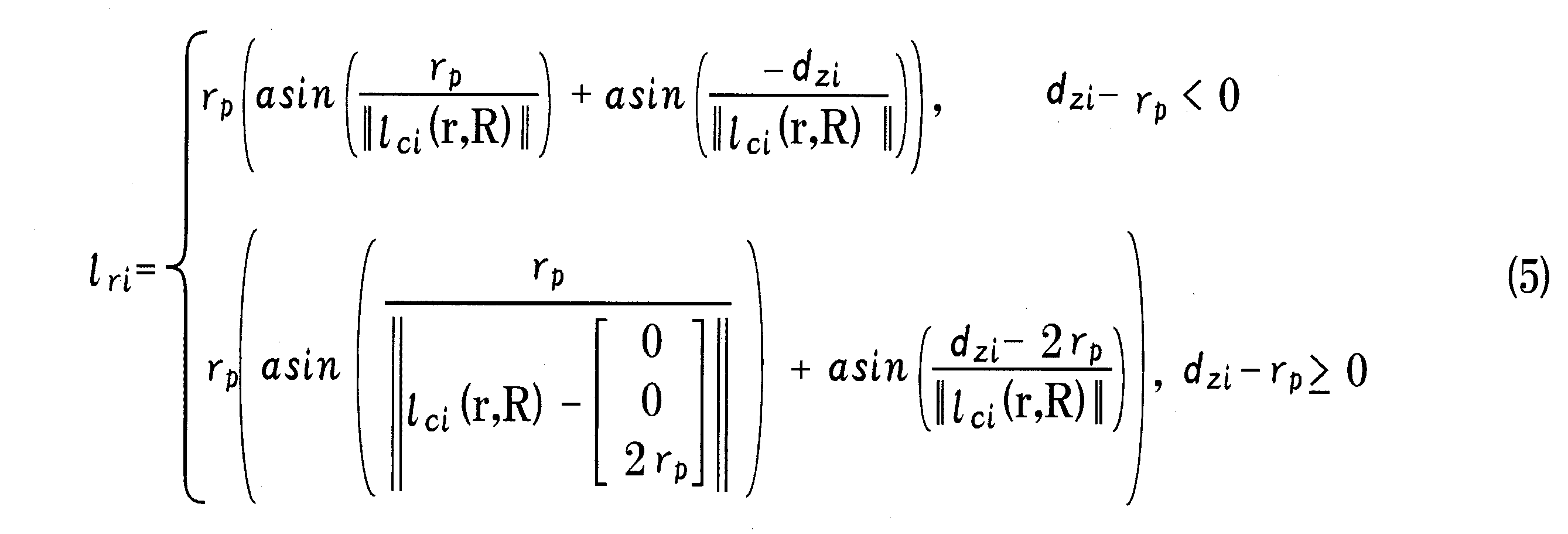
- “lri” shown in Expression (4) is the length of each of the four cables 4 connected to the upper end side of the movable platform 3 in contact with the pulley 11.
- “lri” represented by the above formula (5) is the four cables 4 connected to the lower end side of the movable platform 3 when the movable platform 3 is in the region above the pulleys 12 to 14.
- the length of each of the portions in contact with the pulley 13 and “lri” shown by the following equation (5) is when the movable platform 3 is in the region below the pulleys 12 to 14.
- the cable 4 does not extend.
- the axial directions of the rotation center axes 15a and 17a are not inclined with respect to the vertical direction (vertical direction).
- the cable robot 1 is calibrated as follows. That is, as shown in FIG. 6, in the calibration of the cable robot 1, first, the positions of the eight pulleys 10 and 12 with respect to the origin Ob (specifically, each of the eight pulleys 10 and 12 and 8 From the pulleys 11, 13, 14 to the movable platform 3 of each of the eight cables 4 when the movable platform 3 is at a predetermined reference position. Is estimated (step S1).
- step S1 for example, the movable platform 3 is fixed at a predetermined position of the frame 2, and this fixed position is set as a reference position of the movable platform 3. Moreover, in step S1 of this form, from the design dimension, each of the eight pulleys 10 and 12 with respect to the origin Ob, and each of the eight cables 4 when the movable platform 3 is at the reference position, The length from the pulleys 11, 13, and 14 to the movable platform 3 is estimated. Note that the lengths from the pulleys 11, 13, and 14 to the movable platform 3 of each of the eight cables 4 when the movable platform 3 is at the reference position may be measured using a measure or the like.
- step S1 the positions of the eight pulleys 10 and 12 with respect to the origin Ob are estimated as a three-dimensional vector, and the positions of the eight pulleys 10 and 12 are expressed by 3 rows and 8 columns of Equation (7). It is shown as a matrix. Further, the length from the pulleys 11, 13, 14 of the eight cables 4 to the movable platform 3 when the movable platform 3 is at the reference position is represented by a matrix of 1 row and 8 columns in Expression (8).
- k1 to k8 are values corresponding to li in equation (6). That is, k1 to k8 are the lengths of the eight cables 4 from the point tp to the movable platform 3, and the lengths of the portions of the eight cables 4 that are in contact with the pulleys 11, 13, and 14, respectively. It is a value corresponding to the sum of In the following description, the position of each of the eight pulleys 10 and 12 estimated in step S1 with respect to the origin Ob is defined as the estimated pulley position, and each of the pulleys 11, 13, and 8 of the eight cables 4 estimated in step S1. The length from 14 to the movable platform 3 is the estimated cable length.
- step S2 the motor of the cable supply winding mechanism 5 is driven to move the movable platform 3 to a plurality of different positions, and the pulleys 11 of each of the eight cables 4 when the movable platform 3 is at each of the plurality of positions. , 13, 14 to the movable platform 3 is obtained (step S2).
- step S2 the movable platform 3 is located at each of a plurality of positions based on the detection result of each of the encoders of the cable supply winding mechanism 5 and the estimated cable length (k1 to k8) estimated in step S1. The length from the pulleys 11, 13, 14 to the movable platform 3 of each of the eight cables 4 is calculated.
- the length li from the pulleys 11, 13, 14 to the movable platform 3 of each of the eight cables 4 when the movable platform 3 is present at each of a plurality of positions. Is calculated.
- ⁇ li is the amount of change in the length of the cable 4 calculated from the rotation amount of the motor (that is, the rotation amount of the reel) detected by the encoder and the outer diameter of the reel.
- the movable platform 3 is moved to 45 different positions, and the lengths li of the eight cables 4 at the 45 positions are calculated.
- the length li calculated in step S2 is assumed to be the actually measured cable length li.
- step S3 the position r and the slope R at which the value of the expression (10) is minimized are specified at each of the 45 locations using, for example, the Nelder-Mead simplex method.
- Expression (10) “Ljreal” is an actually measured cable length li of eight cables 4 at each of 45 positions, and is a matrix of 1 row ⁇ 8 columns. “Zj” is the minimum height of the representative point Oe when the movable platform 3 is moved to 45 positions, and “kg” is a constant obtained experimentally.
- step S2 if there is a case where the cable 4 is slack when there is the movable platform 3 at each of the 45 positions, there is an abnormality in the 45 positions r and inclinations R specified in step S3. Contains the value. Therefore, after that, abnormal values are excluded from the 45 positions r and slopes R specified in step S3 (step S4).
- step S5 based on the actually measured cable length li, the positions bi of the eight pulleys 10 and 12 with respect to the origin Ob, and the pulleys 11 and 13 of the plurality of cables 4 when the movable platform 3 is at the reference position. , 14 to the movable platform 3 are identified (step S5). Specifically, in step S5, based on the position r and inclination R specified in step S3 and the measured cable length li, the position bi with respect to the origin Ob of each of the eight pulleys 10 and 12, and the reference position The lengths ki from the pulleys 11, 13, and 14 to the movable platform 3 of each of the eight cables 4 when the movable platform 3 is present are specified.
- step S5 among the remaining positions r and slope R obtained by removing the position r and slope R excluded in step S4 from the 45 positions r and slope R specified in step S3.
- the length ki is a value corresponding to li in Equation (6).
- step S5 for example, the position bi and the length ki at which the value of Expression (11) is minimized are specified by using the Broden-Fletcher-Goldfarb-Shanno (BFGS) quasi-Newton method.
- BFGS Broden-Fletcher-Goldfarb-Shanno
- the position bi specified in step S5 is set as a specific pulley position bi
- the length ki specified in step S5 is set as a specific cable length ki.
- step S6 the difference between the specific pulley position bi of each of the eight pulleys 10 and 12 specified in step S5 and the estimated pulley position of each of the eight pulleys 10 and 12 estimated in step S1 is minimized.
- the specific pulley position bi is corrected (step S6).
- “b” is defined as shown in Expression (12)
- “A” is defined as shown in Expression (13)
- Ra and ra that minimize Expression (14) are first calculated in Step S6. .
- step S6 based on the calculated Ra and ra, the specific pulley positions bi of the eight pulleys 10 and 12 specified in step S5 are translated and rotated for correction.
- step S7 for example, when the difference between the specific cable length ki specified in the previous step S5 and the specific cable length ki specified in the current step S5 is within a predetermined range, and / or When the difference between the corrected specific pulley position bi obtained in step S6 and the corrected specific pulley position bi obtained in step S6 is within a predetermined range, it is determined that the calibration is to be ended. If this condition is not satisfied, it returns to step S1 and determines that the calibration is continued. In this case, the steps S1 to S6 are executed at least twice.
- step S7 for example, the remaining position r and inclination R obtained by removing the position r and inclination R excluded in step S4 from the 45 positions r and inclination R specified in step S3, and the actual cable length Based on the length li, the pulley position bi and the specific cable length ki are specified in the same manner as in step S5. Further, the pulley position bi specified in step S7 and the specific pulley position bi specified in step S5 (that is, specified based on the 35 positions r and the inclination R and the measured cable length li).
- step S1 after step S7 the estimated pulley position is estimated based on the specific pulley position bi, and the estimated cable length is estimated based on the specific cable length ki.
- the corrected specific pulley position bi obtained in step S6 is set as the estimated pulley position
- the specific cable length ki specified in step S5 is set as the estimated cable length.
- step S2 after the calibration of the cable robot 1 is started, in step S2 up to a predetermined number of times, the movable platform 3 is controlled by controlling each of the eight motors of the cable supply winding mechanism 5 by proportional differential control. move.
- step S2 after the calibration of the cable robot 1 is started, in step S2 after the predetermined number of times, the movable platform 3 is controlled by controlling each of the motors of the eight cable supply winding mechanisms 5 by robust control such as sliding mode control. move.
- step S1 of this form is a parameter estimation step
- step S2 is a cable length measurement step
- step S3 is a first parameter specifying step
- step S4 is an abnormal value exclusion step
- Step S5 is a second parameter specifying step
- step S6 is a pulley position correction step
- step S7 is an end determination step.
- the parameter specifying step is configured by steps S3 to S5.
- steps S1 to S7 are executed in the calibration method of the present embodiment.
- the estimated pulley position is estimated based on the specific pulley position bi
- the estimated cable length is estimated based on the specific cable length ki. Therefore, according to the calibration method of the present embodiment, the cable robot 1 can be calibrated using the function originally provided in the cable robot 1.
- step S3 after specifying the position r with respect to the origin Ob of the movable platform 3 at 45 locations and the inclination R of the movable platform 3 with respect to the reference coordinate system, in step S5, the position r specified in step S3. And the specific pulley position bi of each of the eight pulleys 10 and 12 and the specific cable length ki of each of the eight cables 4 are specified using the inclination R. Therefore, in this embodiment, for example, steps S3 and S4 are omitted, and in step S5, using the formula (11), the position r of the movable platform 3 with respect to the origin Ob at 45 locations, and the movable platform 3 with respect to the reference coordinate system.
- step S5 This makes it possible to reduce the burden of computation processing.
- step S4 abnormal values are excluded from the 45 positions r and slopes R specified in step S3. Further, in the present embodiment, in step S5, the remaining positions r and slopes R except for the position r and slope R excluded in step S4 from among the 45 positions r and slopes R specified in step S3.
- step S6 the specific pulley positions bi of the eight pulleys 10 and 12 specified in step S5, the estimated pulley positions of the eight pulleys 10 and 12 estimated in step S1, and The specific pulley position bi is corrected so that the difference between the two is minimized.
- step S1 after step S7 the corrected specific pulley position bi obtained in step S6 is set as the estimated pulley position. Therefore, in this embodiment, it is possible to increase the calibration accuracy of the cable robot 1.
- step S5 there are 24 parameters for the position bi specified in step S5, and there are 8 parameters for the length ki specified in step S5. That is, although the number of parameters specified in step S5 is 32, in this embodiment, in step S2, the movable platform 3 is moved to 45 different positions, and the measured cable lengths at 45 different positions are obtained.
- 32 parameters are specified based on 35 positions r and slopes R. That is, in this embodiment, 32 parameters are specified based on the position r and the slope R that are equal to or greater than the number of parameters. Therefore, in this embodiment, it is possible to specify 32 parameters with high accuracy in step S5.
- step S2 after the calibration of the cable robot 1 is started, in step S2 up to a predetermined number of times, the movable platform 3 is moved by controlling each of the motors of the eight cable supply winding mechanisms 5 by proportional differential control, After the calibration of the cable robot 1 is started, in step S2 after the predetermined number of times, the movable platform 3 is moved by controlling each of the motors of the eight cable supply winding mechanisms 5 by robust control. Therefore, in this embodiment, even when the accuracy of the estimated pulley position and the estimated cable length estimated in step S1 up to the predetermined number of times after the start of the calibration of the cable robot 1 is low, the movable platform 3 is moved in step S2. It is possible to prevent the cable 4 from being disconnected.
- the estimation is performed at the step S1 up to a predetermined number of times after the calibration of the cable robot 1 is started. If the accuracy of the estimated pulley position and the estimated cable length is low, the cable 4 may be disconnected in step S2.
- step S3 In the form described above, after specifying the position r with respect to the origin Ob of the movable platform 3 at 45 locations and the inclination R of the movable platform 3 with respect to the reference coordinate system in step S3, the position specified in step S3 in step S5.
- the specific pulley position bi of each of the eight pulleys 10 and 12 and the specific cable length ki of each of the eight cables 4 are specified using r and the inclination R.
- steps S3 and S4 may be omitted.
- step S5 using the expression (11) (that is, based on the actually measured cable length li (ie, Ljreal)), the position r with respect to the origin Ob of the movable platform 3 at the 35 locations, and the reference
- the inclination R of the movable platform 3 with respect to the coordinate system, the specific pulley positions bi of the eight pulleys 10 and 12, and the specific cable lengths ki of the eight cables 4 may be specified by a single calculation. .
- step S4 abnormal values are excluded from the 45 positions r and inclinations R specified in step S3. However, the supply and winding of the cable 4 are performed so that the cable 4 does not become slack. If taking is performed, step S4 may be omitted.
- the specific pulley position bi is corrected in step S6. However, if the correction amount of the specific pulley position bi in step S6 is small, step S6 may be omitted.
- step S2 the movable platform 3 is moved to 45 different positions and the measured cable length li at 45 different positions is calculated.
- the movable platform 3 is moved. May be 46 or more, or 44 or less.
- the number of parameters specified in step S5 is 32, in step S2 so that 32 parameters can be specified based on at least 32 positions r and slopes R in step S5. It is preferable that the number of positions for moving the movable platform 3 is set.
- step S5 32 parameters can be specified based on at least 16 positions r and inclinations R. Further, according to the study by the present inventor, when 32 parameters are specified based on at least 35 positions r and inclinations R in step S5 as in the above-described form, 32 parameters are accurately determined. It becomes possible to specify. Therefore, considering that there are the position r and the inclination R that are excluded in step S4, the movable platform 3 is moved to 45 different positions in step S2 as in the above-described form, and the 45 different positions are moved. It is preferable to calculate the actual measured cable length li.
- the number of cables 4 included in the cable robot 1 is eight, but the number of cables 4 included in the cable robot 1 may be seven, or may be nine or more. .
- the range of “i” in formulas (1) to (6) and the like changes according to the number of cables 4 provided in the cable robot 1.
- the cable 4 does not extend in the calibration.
- the calibration can be performed on the assumption that the cable 4 extends.
- the equations (1) to (6) may be changed in consideration of the elongation of the cable 4.
- each of the four cables 4 connected to the upper end side of the movable platform 3 is hung on two pulleys 10 and 11 that are adjacent to each other in a direction orthogonal to the axial direction of the rotation and the vertical direction. ing.
- each of the four cables 4 connected to the upper end side of the movable platform 3 is hung on three or more adjacent pulleys in a direction perpendicular to the axial direction and the vertical direction of the rotation.
- the pulley portion is constituted by three or more pulleys.
- each of the four cables 4 connected to the upper end side of the movable platform 3 may be hung on one pulley 10.
- the pulley 10 is a first pulley and a second pulley.
- the pulley 10 is constituted by the pulley 10.
- each of the four cables 4 connected to the lower end side of the movable platform 3 has two pulleys 12 and 13 adjacent in the direction perpendicular to the axial direction and the vertical direction of the rotation. Is suspended on pulleys 12 to 14 including
- each of the four cables 4 connected to the lower end side of the movable platform 3 includes a plurality of pulleys including three or more pulleys adjacent in the direction perpendicular to the axial direction and the vertical direction of the rotation. It may be hung on a pulley. In this case, a pulley part is comprised by the some pulley with which each of the four cables 4 is hung.
- Each of the four cables 4 connected to the lower end side of the movable platform 3 may be hung on one pulley 12.
- the pulley 12 is a first pulley and a second pulley.
- the pulley portion is constituted by the pulley 12.
- step S2 after the calibration of the cable robot 1 is started, the motors of the eight cable supply winding mechanisms 5 are controlled by proportional differential control in step S2 up to a predetermined number of times.
- step S2 up to a predetermined number of times after the start of calibration of one, each of the eight motors of the cable supply winding mechanism 5 may be controlled by speed control.
- the video camera is mounted on the movable platform 3, but an object other than the video camera may be mounted on the movable platform 3. That is, the cable robot 1 having the above-described form is a robot for moving the video camera in the air, but the cable robot 1 may be a robot used for other purposes.
Landscapes
- Engineering & Computer Science (AREA)
- Robotics (AREA)
- Mechanical Engineering (AREA)
- Health & Medical Sciences (AREA)
- General Health & Medical Sciences (AREA)
- Orthopedic Medicine & Surgery (AREA)
- Manipulator (AREA)
Abstract
【課題】ケーブルロボットが元々備えている機能を利用してキャリブレーションを行うことが可能となるケーブルロボットのキャリブレーション方法を提案する。 【解決手段】このキャリブレーション方法では、異なる複数の位置に可動プラットフォームがあるときの第2プーリから可動プラットフォームまでのケーブルの長さを、推定されたケーブル長さとエンコーダでの検出結果に基づいて算出し、算出されたケーブル長さに基づいて、複数の各位置での可動プラットフォームの、原点に対する位置および基準座標系に対する傾きと、原点に対する第1プーリの位置と、基準位置に可動プラットフォームがあるときの第2プーリから可動プラットフォームまでのケーブルの長さとを特定するとともに、ステップS7を経た後のステップS1において、特定されたプーリ位置に基づいてプーリ位置を推定し、特定されたケーブル長さに基づいてケーブル長さを推定する。
Description
本発明は、複数のケーブルと、複数のケーブルの一端側が連結されるとともに3次元方向へ移動可能な可動プラットフォームとを備えるケーブルロボットのキャリブレーション方法に関する。
従来、複数のケーブルと、複数のケーブルの一端側が連結されるとともに3次元方向へ移動可能な可動プラットフォームとを備えるケーブルロボットが知られている(たとえば、特許文献1参照)。特許文献1に記載のケーブルロボットでは、たとえば、可動プラットフォームの上端側に4本のケーブルの一端側が連結され、可動プラットフォームの下端側に8本のケーブルの一端側が連結されている。12本のケーブルの他端側は、リールに巻回されており、リールは、モータに連結されている。リールおよびモータは、ケーブルロボットの下端側に配置されている。可動プラットフォームの上端側に連結されるケーブルは、ケーブルロボットのフレームの上端側に取り付けられるプーリに掛けられている。また、可動プラットフォームの下端側に連結されるケーブルは、フレームの下端側に取り付けられるプーリに掛けられている。
特許文献1に記載のケーブルロボットでは、可動プラットフォームが移動したときの可動プラットフォームの位置と姿勢とを保つために、キャリブレーションを行う必要がある。本願発明者の検討によると、このキャリブレーションは、たとえば、モーションキャプチャ等のセンサを用いて行うことが可能である。しかしながら、モーションキャプチャ等のセンサを用いてキャリブレーションを行う場合には、ケーブルロボットを実際に使用する際に不要なセンサを準備しなければならない。
そこで、本発明の課題は、ケーブルロボットが元々備えている機能を利用してケーブルロボットのキャリブレーションを行うことが可能となるケーブルロボットのキャリブレーション方法を提案することにある。
上記の課題を解決するため、本発明のケーブルロボットのキャリブレーション方法は、7本以上の複数のケーブルと、複数のケーブルの一端側が連結されるとともに3次元方向へ移動可能な可動プラットフォームと、複数のケーブルのそれぞれの他端側が巻回される複数のリールと、複数のリールのそれぞれを回転させる複数のモータと、複数のモータのそれぞれの回転量を検出する複数のエンコーダと、水平方向を回転の軸方向として回転する1個以上のプーリを有し複数のケーブルのそれぞれが掛けられる複数のプーリ部と、上下方向を回動の軸方向として回動するとともに複数のプーリ部のそれぞれを回転可能に保持する複数のプーリ保持部材と、複数のプーリ保持部材のそれぞれの回動中心となる複数の回動中心軸と、複数の回動中心軸が取り付けられるフレームとを備えるケーブルロボットのキャリブレーション方法であって、プーリ部が有するプーリのうち、リールから引き出されるケーブルが最初に接触するプーリを第1プーリとし、プーリ部が有するプーリのうち、可動プラットフォームから引き出されるケーブルが最初に接触するプーリを第2プーリとすると、所定の原点に対する複数の第1プーリのそれぞれの位置と、所定の基準位置に可動プラットフォームがあるときの複数のケーブルのそれぞれの第2プーリから可動プラットフォームまでの長さとを推定するパラメータ推定ステップと、パラメータ推定ステップで推定された複数の第1プーリのそれぞれの位置を推定プーリ位置とし、パラメータ推定ステップで推定された複数のケーブルのそれぞれの第2プーリから可動プラットフォームまでの長さを推定ケーブル長さとすると、パラメータ推定ステップ後、複数のモータを駆動して可動プラットフォームを異なる複数の位置に動かすとともに、複数の位置のそれぞれに可動プラットフォームがあるときの複数のケーブルのそれぞれの第2プーリから可動プラットフォームまでの長さを、複数のエンコーダのそれぞれでの検出結果と推定ケーブル長さとに基づいて算出するケーブル長さ測定ステップと、ケーブル長さ測定ステップで算出された複数のケーブルのそれぞれの第2プーリから可動プラットフォームまでの長さを実測ケーブル長さとすると、実測ケーブル長さに基づいて、ケーブル長さ測定ステップで可動プラットフォームを動かしたときの各位置における可動プラットフォームの原点に対する位置および所定の基準座標系に対する傾きを特定するとともに、実測ケーブル長さに基づいて、複数の第1プーリのそれぞれの原点に対する位置と、基準位置に可動プラットフォームがあるときの複数のケーブルのそれぞれの第2プーリから可動プラットフォームまでの長さを特定するパラメータ特定ステップと、パラメータ特定ステップでの特定結果に基づいて、パラメータ推定ステップに戻るのかそれともケーブルロボットのキャリブレーションを終了させるのかを判定する終了判定ステップとを備え、パラメータ特定ステップで特定された複数の第1プーリのそれぞれの原点に対する位置を特定プーリ位置とし、パラメータ特定ステップで特定された複数のケーブルのそれぞれの第2プーリから可動プラットフォームまでの長さを特定ケーブル長さとすると、終了判定ステップを経た後のパラメータ推定ステップでは、特定プーリ位置に基づいて推定プーリ位置を推定し、特定ケーブル長さに基づいて推定ケーブル長さを推定することを特徴とする。
本発明のケーブルロボットのキャリブレーション方法は、上述のパラメータ推定ステップと、ケーブル長さ測定ステップと、パラメータ特定ステップと、終了判定ステップとを備えている。また、本発明では、終了判定ステップを経た後のパラメータ推定ステップにおいて、特定プーリ位置に基づいて推定プーリ位置を推定し、特定ケーブル長さに基づいて推定ケーブル長さを推定している。そのため、本発明のケーブルロボットのキャリブレーション方法によれば、ケーブルロボットが元々備えている機能を利用してケーブルロボットのキャリブレーションを行うことが可能になる。
本発明において、Nを7以上の整数とすると、ケーブルロボットは、N本のケーブルを備え、ケーブル長さ測定ステップでは、少なくとも4N箇所の異なる複数の位置に可動プラットフォームを動かして、実測ケーブル長さを算出することが好ましい。このように構成すると、パラメータ特定ステップにおいて、各種のパラメータを精度良く特定することが可能になる。
本発明において、パラメータ特定ステップは、実測ケーブル長さに基づいて、ケーブル長さ測定ステップで可動プラットフォームを動かしたときの各位置における可動プラットフォームの原点に対する位置および基準座標系に対する傾きを特定する第1パラメータ特定ステップと、実測ケーブル長さと第1パラメータ特定ステップで特定された可動プラットフォームの位置および傾きとに基づいて、特定プーリ位置と特定ケーブル長さとを特定する第2パラメータ特定ステップとを備えることが好ましい。このように構成すると、パラメータ特定ステップで特定される各パラメータを一度の演算で特定する場合と比較して、パラメータ特定ステップで特定される各パラメータを特定する際の演算処理の負担を軽減することが可能になる。
本発明において、パラメータ特定ステップは、第1パラメータ特定ステップで特定された可動プラットフォームの位置および傾きの中から異常値を除外する異常値除外ステップを備え、第2パラメータ特定ステップでは、異常値除外ステップで除外された可動プラットフォームの位置および傾きを除く可動プラットフォームの位置および傾きと実測ケーブル長さとに基づいて、特定プーリ位置と特定ケーブル長さとを特定することが好ましい。このように構成すると、第2パラメータ特定ステップにおいて、特定プーリ位置と特定ケーブル長さとを精度良く特定することが可能になる。
本発明において、ケーブルロボットのキャリブレーション方法は、パラメータ特定ステップと終了判定ステップとの間に、複数のプーリのそれぞれの特定プーリ位置と、複数のプーリのそれぞれの推定プーリ位置との差が最小になるように、特定プーリ位置を補正するプーリ位置補正ステップを備え、終了判定ステップを経た後のパラメータ推定ステップでは、特定ケーブル長さを推定ケーブル長さとし、プーリ位置補正ステップで補正された特定プーリ位置を推定プーリ位置とすることが好ましい。このように構成すると、ケーブルロボットのキャリブレーションの精度を高めることが可能になる。
本発明において、ケーブルロボットのキャリブレーションの開始後、所定回数までのケーブル長さ測定ステップでは、比例微分制御によって複数のモータを制御し、ケーブルロボットのキャリブレーションの開始後、所定回数以降のケーブル長さ測定ステップでは、ロバスト制御によって複数のモータを制御することが好ましい。このように構成すると、ケーブルロボットのキャリブレーションの開始後の所定回数までのパラメータ推定ステップで推定される推定プーリ位置や推定ケーブル長さの精度が低くても、ケーブル長さ測定ステップにおいて可動プラットフォームを動かしたときのケーブルの断線を防止することが可能になる。これに対して、ケーブルロボットのキャリブレーションの開始後の最初のケーブル長さ測定ステップからロバスト制御によって複数のモータを制御すると、ケーブルロボットのキャリブレーションの開始後の所定回数までのパラメータ推定ステップで推定される推定プーリ位置や推定ケーブル長さの精度が低かった場合に、ケーブル長さ測定ステップにおいてケーブルが断線するおそれがある。
以上のように、本発明のケーブルロボットのキャリブレーション方法によれば、ケーブルロボットが元々備えている機能を利用してケーブルロボットのキャリブレーションを行うことが可能になる。
以下、図面を参照しながら、本発明の実施の形態を説明する。
(ケーブルロボットの構成)
図1は、本発明の実施の形態にかかるキャリブレーション方法でキャリブレーションされるケーブルロボット1の正面図である。図2は、図1に示すケーブルロボット1の平面図である。図3は、図1のE部および可動プラットフォーム3の構成を説明するための正面図である。図4は、図3のF-F方向から可動プラットフォーム3およびプーリ10、11等を示す平面図である。
図1は、本発明の実施の形態にかかるキャリブレーション方法でキャリブレーションされるケーブルロボット1の正面図である。図2は、図1に示すケーブルロボット1の平面図である。図3は、図1のE部および可動プラットフォーム3の構成を説明するための正面図である。図4は、図3のF-F方向から可動プラットフォーム3およびプーリ10、11等を示す平面図である。
本形態のケーブルロボット1は、スポーツ中継等に使用されるビデオカメラを空中で移動させるためのロボットである。このケーブルロボット1は、フレーム2と、ビデオカメラ(図示省略)が搭載される可動プラットフォーム3と、可動プラットフォーム3に一端側が連結される8本のケーブル4と、8本のケーブル4の他端側のそれぞれが連結される8個のケーブル供給巻取機構5とを備えている。可動プラットフォーム3は、8本のケーブル4に支持されており、3次元方向へ移動可能となっている。フレーム2は、その外形が略直方体状となるように形成されている。このフレーム2は、四隅に配置される4本の支柱6を備えている。4本の支柱6によって形成される空間は、可動プラットフォーム3が移動する移動空間となっている。
可動プラットフォーム3は、略直方体状に形成されている。8本のケーブル4のうちの4本のケーブル4の一端側は、可動プラットフォーム3の上端側に連結され、残りの4本のケーブル4の一端側は、可動プラットフォーム3の下端側に連結されている。たとえば、8本のケーブル4のうちの4本のケーブル4の一端側は、可動プラットフォーム3の上端側の四隅の近傍に連結され、残りの4本のケーブル4の一端側は、可動プラットフォーム3の下端側の四隅の近傍に連結されている。可動プラットフォーム3は、その先端側にケーブル4の一端側が連結される連結部材8を備えている。連結部材8は、ケーブル4に捩れが生じないように、可動プラットフォーム3の本体部に対して回動可能となっている。
ケーブル供給巻取機構5は、フレーム2の下端側に取り付けられている。このケーブル供給巻取機構5は、ケーブル4の他端側が巻回されるリールと、リールを回転させるモータと、モータの動力をリールに伝達する動力伝達機構と、モータの回転量を検出するエンコーダとを備えている。動力伝達機構は、リールと同心状に配置されるボールネジスプラインを備えている。このボールネジスプラインとモータとは、プーリおよびベルトを介して連結されている。ケーブル供給巻取機構5では、モータが駆動すると、ボールネジスプラインが回転して、リールが回転しながら軸方向へ直線的に移動する。本形態では、リールからのケーブル4の繰出位置およびリールへのケーブル4の巻取位置が一定の位置から動かないように、リールが回転しながら軸方向へ移動する。
可動プラットフォーム3の上端側に連結される4本のケーブル4のそれぞれは、4本の支柱6のそれぞれの上端側に配置されるプーリ10、11に掛けられている。すなわち、可動プラットフォーム3の上端側から引き出された4本のケーブル4のそれぞれは、4本の支柱6のそれぞれの上端側に配置されるプーリ10、11に掛けられた後、フレーム2の下端側に引き回されて、ケーブル供給巻取機構5のリールに巻回されている。一方、可動プラットフォーム3の下端側に連結される4本のケーブル4のそれぞれは、4本の支柱6のそれぞれの略中心位置に配置されるプーリ12~14に掛けられている。すなわち、可動プラットフォーム3の下端側から引き出された4本のケーブル4のそれぞれは、4本の支柱6のそれぞれの略中心位置に配置されるプーリ12~14に掛けられた後、フレーム2の下端側に引き回されて、ケーブル供給巻取機構5のリールに巻回されている。
本形態の可動プラットフォーム3は、プーリ12~14よりも上側の領域とプーリ12~14よりも下側の領域との両方の領域に移動可能となっている(図1参照)。プーリ12~14よりも上側の領域内に可動プラットフォーム3があるとき、および、プーリ12~14よりも下側の領域内に可動プラットフォーム3があるときのいずれの場合においても、8本のケーブル4の全てが可動プラットフォーム3を引っ張っている。また、プーリ12~14よりも上側の領域内に可動プラットフォーム3があるときには、可動プラットフォーム3の上端側に連結される4本のケーブル4が可動プラットフォーム3の自重を支え、プーリ12~14よりも下側の領域内に可動プラットフォーム3があるときには、8本のケーブル4が可動プラットフォーム3の自重を支えている。
プーリ10、11は、水平方向を回転の軸方向とする回転が可能となるように、プーリ保持部材15に保持されている。プーリ10とプーリ11とは、その回転の軸方向と上下方向とに直交する方向で隣接するように配置されている。プーリ10のピッチ円径とプーリ11のピッチ円径とは等しくなっている。また、プーリ10の回転中心とプーリ11の回転中心とは同じ高さに配置されている。プーリ保持部材15には、下方向に突出する回動中心軸15aが形成されている。フレーム2は、支柱6の上端側に固定される支持部材16を備えており、回動中心軸15aは、支持部材16に回動可能に取り付けられている。すなわち、プーリ保持部材15は、回動中心軸15aを中心にして、かつ、上下方向を回動の軸方向として回動可能となっている。
本形態では、ケーブル供給巻取機構5のリールから引き出されるケーブル4が最初にプーリ10に接触し、かつ、可動プラットフォーム3から引き出されるケーブル4が最初にプーリ11に接触するように、プーリ10が外側に配置され、プーリ11が内側に配置されている。本形態のプーリ10は、第1プーリであり、プーリ11は、第2プーリである。また、本形態では、プーリ10とプーリ11とによってプーリ部が構成されている。
プーリ12~14は、水平方向を回転の軸方向とする回転が可能となるように、プーリ保持部材17に保持されている。プーリ12とプーリ13とは、その回転の軸方向と上下方向とに直交する方向で隣接するように配置されている。また、プーリ13とプーリ14とは、上下方向で重なるように配置されている。プーリ12のピッチ円径とプーリ13のピッチ円径とプーリ14のピッチ円径とは等しくなっている。また、プーリ12の回転中心とプーリ13の回転中心とは同じ高さに配置され、プーリ13の回転中心とプーリ14の回転中心とは、プーリ12とプーリ13との隣接方向において同じ位置に配置されている。
プーリ保持部材17には、下方向に突出する回動中心軸17aが形成されている。フレーム2は、支柱6の略中心位置に固定される支持部材18を備えており、回動中心軸17aは、支持部材18に回動可能に取り付けられている。すなわち、プーリ保持部材17は、回動中心軸17aを中心にして、かつ、上下方向を回動の軸方向として回動可能となっている。上下方向から見たときに、同じ支柱6に固定される支持部材16、18に回動可能に取り付けられるプーリ保持部材15の回動中心軸15aの軸心と回動中心軸17aの軸心とが一致している。
本形態では、ケーブル供給巻取機構5のリールから引き出されるケーブル4が最初にプーリ12に接触するとともに、プーリ12~14よりも上側の領域内にあるときの可動プラットフォーム3から引き出されるケーブル4が最初にプーリ13に接触し、かつ、プーリ12~14よりも下側の領域内にあるときの可動プラットフォーム3から引き出されるケーブル4が最初にプーリ14に接触するように、プーリ12が外側に配置され、プーリ13、14が内側に配置されている。本形態のプーリ12は、第1プーリであり、プーリ13、14は、第2プーリである。また、本形態では、プーリ12~14によってプーリ部が構成されている。
以上のように構成されたケーブルロボット1では、ケーブル供給巻取機構5を構成するエンコーダでの検出結果に基づいてモータを駆動制御することで、可動プラットフォーム3がフレーム2内の任意の位置へ移動する。
(ケーブルロボットのキャリブレーション方法)
図5は、図3のG部の拡大図である。図6は、本発明の実施の形態にかかるキャリブレーション方法のフローを示すフローチャートである。
図5は、図3のG部の拡大図である。図6は、本発明の実施の形態にかかるキャリブレーション方法のフローを示すフローチャートである。
まず、ケーブルロボット1のキャリブレーションを行うための前提を説明する。ケーブルロボット1において可動プラットフォーム3等の位置を特定するための所定の原点を「Ob」とする(図3、図4参照)。また、可動プラットフォーム3の代表点を「Oe」とする(図3、図4参照)。代表点Oeは、たとえば、可動プラットフォーム3の質量中心である。ケーブルロボット1では、以下の関係式が成立する。





式(1)において、「r」は、原点Obに対する代表点Oeの位置(相対位置)を表わす3次元ベクトルである。本形態では、「r」は、可動プラットフォーム3の、原点Obに対する位置となっている。「R」は、基準座標系(xb-yb-zb座標系)に対する可動プラットフォーム3の傾き(具体的には、基準座標系に対する可動プラットフォーム3の座標系(xe-ye-ze座標系)の傾き)を表わす3行3列の回転行列である。すなわち、「R」は、可動プラットフォーム3の姿勢を表わす3行3列の回転行列である。「Pi」は、8個の連結部材8のそれぞれと8本のケーブル4のそれぞれとの連結点の、代表点Oeに対する(相対位置)を表す3次元ベクトルであり、i=1~8である。「bi」は、原点Obに対する8個のプーリ10、12のそれぞれの位置(相対位置)を表す3次元ベクトルであり、i=1~8である。具体的には、「bi」は、8個のプーリ10、12のそれぞれと8本のケーブル4のそれぞれとの接触部分の原点Obに対する位置を表す3次元ベクトルである。なお、本形態では、上下方向から見たときに、8個のプーリ10、12のそれぞれと8本のケーブル4のそれぞれとの接触部分は、回動中心軸15a、17aの軸心と一致している。
また、式(1)において、「lp」は、プーリ10、12とケーブル4との接触部分と、プーリ11、13、14の中心との水平方向における距離である(図3参照)。「lci(r、R)」は、8個の連結部材8のそれぞれと8本のケーブル4のそれぞれとの連結点とプーリ11、13、14の中心との距離を、位置rと傾きRとから求める関数であり、i=1~8である。また、「lci(r、R)」は、3次元のベクトルである。αi(r、R)は、回動中心軸15a、17aを中心に回動するプーリ11、13、14のそれぞれの基準座標系に対する角度αi(図4参照)を、位置rと傾きRとから求める関数であり、i=1~8である。
式(2)、(3)において、「rp」は、プーリ11、13、14のピッチ円半径である(図5参照)。また、可動プラットフォーム3から引き出されるケーブル4がプーリ11、13、14に接触し始める点をtpとすると(図5参照)、「lfi」は、8個の連結部材8のそれぞれと8本のケーブル4のそれぞれとの連結点と8個の点tpのそれぞれとの距離であり、i=1~8である。すなわち、「lfi」は、8本のケーブル4のそれぞれの、点tpから可動プラットフォーム3までの長さである。なお、式(2)で示す「lfi」は、可動プラットフォーム3の上端側に連結される4本のケーブル4のそれぞれの、点tpから可動プラットフォーム3までの長さであり、式(3)で示す「lfi」は、可動プラットフォーム3の下端側に連結される4本のケーブル4のそれぞれの、点tpから可動プラットフォーム3までの長さである。
式(4)、(5)において、「dzi」は、8個の連結部材8のそれぞれと8本のケーブル4のそれぞれとの連結点とプーリ11、13、14の中心のそれぞれとの上下方向における距離であり(図3参照)、i=1~8である。「lri」は、図5に示すように、8本のケーブル4のそれぞれの、プーリ11、13、14に接触している部分の長さであり、i=1~8である。なお、式(4)で示す「lri」は、可動プラットフォーム3の上端側に連結される4本のケーブル4のそれぞれの、プーリ11に接触している部分の長さである。また、式(5)の上式で示す「lri」は、プーリ12~14よりも上側の領域内に可動プラットフォーム3があるときの、可動プラットフォーム3の下端側に連結される4本のケーブル4のそれぞれの、プーリ13に接触している部分の長さであり、式(5)の下式で示す「lri」は、プーリ12~14よりも下側の領域内に可動プラットフォーム3があるときの、可動プラットフォーム3の下端側に連結される4本のケーブル4のそれぞれの、プーリ14に接触している部分の長さである。
本形態では、式(6)に示す「li」が、8本のケーブル4のそれぞれの、プーリ11、13、14から可動プラットフォーム3までの長さであり、i=1~8である。なお、本形態のケーブルロボット1のキャリブレーションでは、ケーブル4は伸びないと仮定している。また、本形態のケーブルロボット1のキャリブレーションでは、回動中心軸15a、17aの軸方向は、鉛直方向(上下方向)に対して傾いていないと仮定している。
以上の前提のもと、本形態では、以下のようにケーブルロボット1のキャリブレーションが行われる。すなわち、図6に示すように、ケーブルロボット1のキャリブレーションでは、まず、原点Obに対する8個のプーリ10、12のそれぞれの位置(具体的には、8個のプーリ10、12のそれぞれと8本のケーブル4のそれぞれとの接触部分の原点Obに対する位置)と、所定の基準位置に可動プラットフォーム3があるときの8本のケーブル4のそれぞれの、プーリ11、13、14から可動プラットフォーム3までの長さとを推定する(ステップS1)。
ステップS1では、たとえば、フレーム2の所定箇所に可動プラットフォーム3を固定し、この固定された位置を可動プラットフォーム3の基準位置とする。また、本形態のステップS1では、設計上の寸法から、原点Obに対する8個のプーリ10、12のそれぞれの位置と、基準位置に可動プラットフォーム3があるときの8本のケーブル4のそれぞれの、プーリ11、13、14から可動プラットフォーム3までの長さとを推定する。なお、基準位置に可動プラットフォーム3があるときの8本のケーブル4のそれぞれの、プーリ11、13、14から可動プラットフォーム3までの長さを、メジャー等を用いて実測しても良い。
また、ステップS1では、原点Obに対する8個のプーリ10、12のそれぞれの位置は、3次元ベクトルとして推定され、8個のプーリ10、12の位置は、式(7)の3行8列の行列で示される。また、基準位置に可動プラットフォーム3があるときの8本のケーブル4のプーリ11、13、14から可動プラットフォーム3までの長さは、式(8)の1行8列の行列で示される。


式(8)において、k1~k8は、式(6)のliに相当する値である。すなわち、k1~k8は、8本のケーブル4のそれぞれの、点tpから可動プラットフォーム3までの長さと、8本のケーブル4のそれぞれの、プーリ11、13、14に接触している部分の長さとの和に相当する値である。以下の説明では、ステップS1で推定された8個のプーリ10、12のそれぞれの原点Obに対する位置を推定プーリ位置とし、ステップS1で推定された8本のケーブル4のそれぞれのプーリ11、13、14から可動プラットフォーム3までの長さを推定ケーブル長さとする。
その後、ケーブル供給巻取機構5のモータを駆動して可動プラットフォーム3を異なる複数の位置に動かすとともに、複数の位置のそれぞれに可動プラットフォーム3があるときの8本のケーブル4のそれぞれの、プーリ11、13、14から可動プラットフォーム3までの長さを求める(ステップS2)。ステップS2では、ケーブル供給巻取機構5のエンコーダのそれぞれでの検出結果とステップS1で推定された推定ケーブル長さ(k1~k8)とに基づいて、複数の位置のそれぞれに可動プラットフォーム3があるときの8本のケーブル4のそれぞれの、プーリ11、13、14から可動プラットフォーム3までの長さを算出する。
具体的には、式(9)を用いて、複数の位置のそれぞれに可動プラットフォーム3があるときの8本のケーブル4のそれぞれの、プーリ11、13、14から可動プラットフォーム3までの長さliを算出する。
式(9)において、δliは、エンコーダで検出されたモータの回転量(すなわち、リールの回転量)とリールの外径とから算出されるケーブル4の長さの変化量である。また、本形態のステップS2では、可動プラットフォーム3を異なる45箇所に動かして、45箇所のそれぞれにおける8本のケーブル4のそれぞれの長さliを算出する。以下の説明では、ステップS2で算出された長さliを実測ケーブル長さliとする。なお、ステップS2では、可動プラットフォーム3の可動領域の全体を使って、異なる45箇所に可動プラットフォーム3を動かすことが好ましい。
式(9)において、δliは、エンコーダで検出されたモータの回転量(すなわち、リールの回転量)とリールの外径とから算出されるケーブル4の長さの変化量である。また、本形態のステップS2では、可動プラットフォーム3を異なる45箇所に動かして、45箇所のそれぞれにおける8本のケーブル4のそれぞれの長さliを算出する。以下の説明では、ステップS2で算出された長さliを実測ケーブル長さliとする。なお、ステップS2では、可動プラットフォーム3の可動領域の全体を使って、異なる45箇所に可動プラットフォーム3を動かすことが好ましい。
その後、実測ケーブル長さliに基づいて、ステップS2で可動プラットフォーム3を動かしたときの各位置における可動プラットフォーム3の原点Obに対する位置rと、基準座標系(xb-yb-zb座標系)に対する可動プラットフォーム3の傾きRとを特定する(ステップS3)。ステップS3では、45箇所のそれぞれにおいて、たとえば、Nelder-Meadシンプレックス法を用いて、式(10)の値が最小となる位置rおよび傾きRを特定する。
 式(10)において「Ljreal」は、45箇所の各位置における8本のケーブル4の実測ケーブル長さliであり、1行8列の行列である。また、「zj」は、可動プラットフォーム3を45箇所に動かしたときの代表点Oeの最小高さであり、「kg」は、実験的に求められた定数である。
ここで、ステップS2において、45箇所の各位置に可動プラットフォーム3があるときにケーブル4が弛んでいる場合があると、ステップS3で特定される45個の位置rと傾きRとの中に異常値が含まれる。そのため、その後、ステップS3で特定された45個の位置rおよび傾きRの中から異常値を除外する(ステップS4)。
その後、実測ケーブル長さliに基づいて、8個のプーリ10、12のそれぞれの原点Obに対する位置biと、基準位置に可動プラットフォーム3があるときの複数のケーブル4のそれぞれの、プーリ11、13、14から可動プラットフォーム3までの長さkiとを特定する(ステップS5)。具体的には、ステップS5では、ステップS3で特定された位置rおよび傾きRと実測ケーブル長さliとに基づいて、8個のプーリ10、12のそれぞれの原点Obに対する位置biと、基準位置に可動プラットフォーム3があるときの8本のケーブル4のそれぞれの、プーリ11、13、14から可動プラットフォーム3までの長さkiとを特定する。より具体的には、ステップS5では、ステップS3で特定された45個の位置rおよび傾きRの中からステップS4で除外された位置rおよび傾きRを除いた残りの位置rおよび傾きRの中の35個の位置rおよび傾きRと実測ケーブル長さliとに基づいて、8個のプーリ10、12のそれぞれの原点Obに対する位置biと、基準位置に可動プラットフォーム3があるときの複数のケーブル4のそれぞれの、プーリ11、13、14から可動プラットフォーム3までの長さkiとを特定する。なお、長さkiは、式(6)のliに相当する値である。
ステップS5では、たとえば、Broyden-Fletcher-Goldfarb-Shanno(BFGS)準ニュートン法を用いて、式(11)の値が最小となる位置biと長さkiとを特定する。
 式(11)において、j=1~35である。以下の説明では、ステップS5で特定された位置biを特定プーリ位置biとし、ステップS5で特定された長さkiを特定ケーブル長さkiとする。
その後、ステップS5で特定された8個のプーリ10、12のそれぞれの特定プーリ位置biと、ステップS1で推定された8個のプーリ10、12のそれぞれの推定プーリ位置との差が最小になるように、特定プーリ位置biを補正する(ステップS6)。式(12)で示すように「b」を定義し、式(13)で示すように「A」を定義すると、ステップS6では、まず、式(14)が最小となるRaおよびraを算出する。



式(12)において、「b1~b8」は、3次元ベクトルであり、「b」は、実際には、3行8列の行列である。式(13)、(14)において、「A」は、3行8列の行列である。また、「Ra」は、3行3列の回転行列であり、「ra」は、3次元ベクトルである。また、ステップS6では、算出されたRaとraとに基づいて、ステップS5で特定された8個のプーリ10、12のそれぞれの特定プーリ位置biを平行移動するとともに回転させて補正する。
その後、ステップS1に戻ってキャリブレーションを継続するのか、それとも、キャリブレーションを終了させるのかを判定する(ステップS7)。ステップS7では、たとえば、前回のステップS5で特定された特定ケーブル長さkiと今回のステップS5で特定された特定ケーブル長さkiの差が所定の範囲内であるとき、および/または、前回のステップS6で求められた補正後の特定プーリ位置biと今回のステップS6で求められた補正後の特定プーリ位置biとの差が所定の範囲内であるときに、キャリブレーションを終了させると判定し、この条件を満たさないときには、ステップS1に戻ってキャリブレーションを継続すると判定する。この場合には、ステップS1~S6の各ステップが少なくとも2回実行される。
あるいは、ステップS7では、たとえば、ステップS3で特定された45個の位置rおよび傾きRの中からステップS4で除外された位置rおよび傾きRを除いた残りの位置rおよび傾きRと実測ケーブル長さliとに基づいて、ステップS5と同様にしてプーリ位置biおよび特定ケーブル長さkiを特定する。また、ステップS7で特定されたプーリ位置biと、ステップS5で特定された(すなわち、35個の位置rおよび傾きRと実測ケーブル長さliとに基づいて特定された)特定プーリ位置biとの差が所定の範囲内にある場合、および/または、ステップS7で特定された特定ケーブル長さkiと、ステップS5で特定された特定ケーブル長さkiとの差が所定の範囲内にある場合に、キャリブレーションを終了させると判定し、この条件を満たさないときには、ステップS1に戻ってキャリブレーションを継続すると判定する。
ステップS7を経た後のステップS1では、特定プーリ位置biに基づいて推定プーリ位置を推定し、特定ケーブル長さkiに基づいて推定ケーブル長さを推定する。具体的には、ステップS7を経た後のステップS1では、ステップS6で求められた補正後の特定プーリ位置biを推定プーリ位置とし、ステップS5で特定された特定ケーブル長さkiを推定ケーブル長さとする。
また、本形態では、ケーブルロボット1のキャリブレーションの開始後、所定回数までのステップS2では、比例微分制御によって、8個のケーブル供給巻取機構5のモータのそれぞれを制御して可動プラットフォーム3を動かす。一方、ケーブルロボット1のキャリブレーションの開始後、所定回数以降のステップS2では、スライディングモード制御等のロバスト制御によって、8個のケーブル供給巻取機構5のモータのそれぞれを制御して可動プラットフォーム3を動かす。
なお、本形態のステップS1は、パラメータ推定ステップであり、ステップS2は、ケーブル長さ測定ステップであり、ステップS3は、第1パラメータ特定ステップであり、ステップS4は、異常値除外ステップであり、ステップS5は、第2パラメータ特定ステップであり、ステップS6は、プーリ位置補正ステップであり、ステップS7は、終了判定ステップである。また、本形態では、ステップS3~S5によってパラメータ特定ステップが構成されている。
(本形態の主な効果)
以上説明したように、本形態のキャリブレーション方法では、ステップS1~S7が実行されている。また、本形態では、ステップS7を経た後のステップS1において、特定プーリ位置biに基づいて推定プーリ位置を推定し、特定ケーブル長さkiに基づいて推定ケーブル長さを推定している。そのため、本形態のキャリブレーション方法によれば、ケーブルロボット1が元々備えている機能を利用してケーブルロボット1のキャリブレーションを行うことが可能になる。
以上説明したように、本形態のキャリブレーション方法では、ステップS1~S7が実行されている。また、本形態では、ステップS7を経た後のステップS1において、特定プーリ位置biに基づいて推定プーリ位置を推定し、特定ケーブル長さkiに基づいて推定ケーブル長さを推定している。そのため、本形態のキャリブレーション方法によれば、ケーブルロボット1が元々備えている機能を利用してケーブルロボット1のキャリブレーションを行うことが可能になる。
本形態では、ステップS3において、45箇所における可動プラットフォーム3の原点Obに対する位置rと、基準座標系に対する可動プラットフォーム3の傾きRとを特定した後に、ステップS5において、ステップS3で特定された位置rおよび傾きRを用いて、8個のプーリ10、12のそれぞれの特定プーリ位置biと、8本のケーブル4のそれぞれの特定ケーブル長さkiとを特定している。そのため、本形態では、たとえば、ステップS3、S4を省略するとともに、ステップS5において式(11)を利用して、45箇所における可動プラットフォーム3の原点Obに対する位置rと、基準座標系に対する可動プラットフォーム3の傾きRと、8個のプーリ10、12のそれぞれの特定プーリ位置biと、8本のケーブル4のそれぞれの特定ケーブル長さkiとを一度の演算で特定する場合と比較して、ステップS5での演算処理の負担を軽減することが可能になる。
本形態では、ステップS4において、ステップS3で特定された45個の位置rおよび傾きRの中から異常値を除外している。また、本形態では、ステップS5において、ステップS3で特定された45個の位置rおよび傾きRの中からステップS4で除外された位置rおよび傾きRを除いた残りの位置rおよび傾きRの中の35個の位置rおよび傾きRと実測ケーブル長さliとに基づいて、8個のプーリ10、12のそれぞれの特定プーリ位置biと、基準位置に可動プラットフォーム3があるときの複数のケーブル4のそれぞれの特定ケーブル長さkiとを特定している。そのため、本形態では、ステップS5において、特定プーリ位置biと特定ケーブル長さliとを精度良く特定することが可能になる。
本形態では、ステップS6において、ステップS5で特定された8個のプーリ10、12のそれぞれの特定プーリ位置biと、ステップS1で推定された8個のプーリ10、12のそれぞれの推定プーリ位置との差が最小になるように、特定プーリ位置biを補正している。また、ステップS7を経た後のステップS1では、ステップS6で求められた補正後の特定プーリ位置biを推定プーリ位置としている。そのため、本形態では、ケーブルロボット1のキャリブレーションの精度を高めることが可能になる。
本形態では、ステップS5で特定される位置biのパラメータは24個であり、また、ステップS5で特定される長さkiのパラメータは8個である。すなわち、ステップS5で特定されるパラメータの数は32個であるが、本形態では、ステップS2において、45箇所の異なる位置に可動プラットフォーム3を動かして、45箇所の異なる位置での実測ケーブル長さliを算出するとともに、ステップS5において、35個の位置rおよび傾きRに基づいて、32個のパラメータを特定している。すなわち、本形態では、パラメータの数以上の位置rおよび傾きRに基づいて、32個のパラメータを特定している。そのため、本形態では、ステップS5において、32個のパラメータを精度良く特定することが可能になる。
本形態では、ケーブルロボット1のキャリブレーションの開始後、所定回数までのステップS2では、比例微分制御によって、8個のケーブル供給巻取機構5のモータのそれぞれを制御して可動プラットフォーム3を動かし、ケーブルロボット1のキャリブレーションの開始後、所定回数以降のステップS2では、ロバスト制御によって、8個のケーブル供給巻取機構5のモータのそれぞれを制御して可動プラットフォーム3を動かしている。そのため、本形態では、ケーブルロボット1のキャリブレーションの開始後の所定回数までのステップS1で推定される推定プーリ位置や推定ケーブル長さの精度が低くても、ステップS2で可動プラットフォーム3を動かす際のケーブル4の断線を防止することが可能になる。これに対して、ケーブルロボット1のキャリブレーションの開始後の最初のステップS2からロバスト制御によって8個のモータを制御すると、ケーブルロボット1のキャリブレーションの開始後の所定回数までのステップS1で推定される推定プーリ位置や推定ケーブル長さの精度が低かった場合に、ステップS2においてケーブル4が断線するおそれがある。
(他の実施の形態)
上述した形態では、ステップS3において、45箇所における可動プラットフォーム3の原点Obに対する位置rと、基準座標系に対する可動プラットフォーム3の傾きRとを特定した後に、ステップS5において、ステップS3で特定された位置rおよび傾きRを用いて、8個のプーリ10、12のそれぞれの特定プーリ位置biと、8本のケーブル4のそれぞれの特定ケーブル長さkiとを特定している。この他にもたとえば、ステップS3、S4を省略しても良い。この場合には、ステップS5において、式(11)を利用して(すなわち、実測ケーブル長さli(すなわち、Ljreal)に基づいて)、35箇所における可動プラットフォーム3の原点Obに対する位置rと、基準座標系に対する可動プラットフォーム3の傾きRと、8個のプーリ10、12のそれぞれの特定プーリ位置biと、8本のケーブル4のそれぞれの特定ケーブル長さkiとを一度の演算で特定すれば良い。
上述した形態では、ステップS3において、45箇所における可動プラットフォーム3の原点Obに対する位置rと、基準座標系に対する可動プラットフォーム3の傾きRとを特定した後に、ステップS5において、ステップS3で特定された位置rおよび傾きRを用いて、8個のプーリ10、12のそれぞれの特定プーリ位置biと、8本のケーブル4のそれぞれの特定ケーブル長さkiとを特定している。この他にもたとえば、ステップS3、S4を省略しても良い。この場合には、ステップS5において、式(11)を利用して(すなわち、実測ケーブル長さli(すなわち、Ljreal)に基づいて)、35箇所における可動プラットフォーム3の原点Obに対する位置rと、基準座標系に対する可動プラットフォーム3の傾きRと、8個のプーリ10、12のそれぞれの特定プーリ位置biと、8本のケーブル4のそれぞれの特定ケーブル長さkiとを一度の演算で特定すれば良い。
上述した形態では、ステップS4において、ステップS3で特定された45個の位置rおよび傾きRの中から異常値を除外しているが、ケーブル4に弛みが生じないようにケーブル4の供給や巻取が行われるのであれば、ステップS4を省略しても良い。また、上述した形態では、ステップS6において、特定プーリ位置biを補正しているが、ステップS6での特定プーリ位置biの補正量がわずかである場合には、ステップS6を省略しても良い。
上述した形態では、ステップS2において、45箇所の異なる位置に可動プラットフォーム3を動かして、45箇所の異なる位置での実測ケーブル長さliを算出しているが、ステップS2において可動プラットフォーム3を動かす位置は、46箇所以上であっても良いし、44箇所以下であっても良い。ただし、ステップS5で特定されるパラメータの数が32個であるため、ステップS5において、少なくとも32個の位置rおよび傾きRに基づいて32個のパラメータを特定することができるように、ステップS2において可動プラットフォーム3を動かす位置の数が設定されることが好ましい。
なお、ステップS5では、最低16個の位置rおよび傾きRに基づいて32個のパラメータを特定することが可能である。また、本願発明者の検討によると、上述した形態のように、ステップS5において、最低でも35個の位置rおよび傾きRに基づいて、32個のパラメータを特定すると、32個のパラメータを精度良く特定することが可能になる。そのため、ステップS4で除外される位置rおよび傾きRがあることを考慮すると、上述した形態のように、ステップS2において、45箇所の異なる位置に可動プラットフォーム3を動かして、45箇所の異なる位置での実測ケーブル長さliを算出することが好ましい。
上述した形態では、ケーブルロボット1が備えるケーブル4の本数は、8本であるが、ケーブルロボット1が備えるケーブル4の本数は、7本であっても良いし、9本以上であっても良い。この場合には、ケーブルロボット1が備えるケーブル4の本数に応じて、式(1)~(6)等の「i」の範囲が変わる。また、上述した形態では、キャリブレーションにおいて、ケーブル4は伸びないと仮定しているが、ケーブル4が伸びるとの前提でキャリブレーションを行うことも可能である。この場合には、ケーブル4の伸びを考慮して式(1)~(6)等を変えれば良い。
上述した形態では、可動プラットフォーム3の上端側に連結される4本のケーブル4のそれぞれは、その回転の軸方向と上下方向とに直交する方向で隣接する2個のプーリ10、11に掛けられている。この他にもたとえば、可動プラットフォーム3の上端側に連結される4本のケーブル4のそれぞれは、その回転の軸方向と上下方向とに直交する方向で隣接する3個以上のプーリに掛けられても良い。この場合には、3個以上のプーリによってプーリ部が構成される。また、可動プラットフォーム3の上端側に連結される4本のケーブル4のそれぞれは、1個のプーリ10に掛けられても良い。この場合には、プーリ10は、第1プーリであるとともに第2プーリである。また、この場合には、プーリ10によってプーリ部が構成される。
同様に、上述した形態では、可動プラットフォーム3の下端側に連結される4本のケーブル4のそれぞれは、その回転の軸方向と上下方向とに直交する方向で隣接する2個のプーリ12、13を含むプーリ12~14に掛けられている。この他にもたとえば、可動プラットフォーム3の下端側に連結される4本のケーブル4のそれぞれは、その回転の軸方向と上下方向とに直交する方向で隣接する3個以上のプーリを含む複数のプーリに掛けられても良い。この場合には、4本のケーブル4のそれぞれが掛けられる複数のプーリによってプーリ部が構成される。また、可動プラットフォーム3の下端側に連結される4本のケーブル4のそれぞれは、1個のプーリ12に掛けられても良い。この場合には、プーリ12は、第1プーリであるとともに第2プーリである。また、この場合には、プーリ12によってプーリ部が構成される。
上述した形態では、ケーブルロボット1のキャリブレーションの開始後、所定回数までのステップS2において、比例微分制御によって、8個のケーブル供給巻取機構5のモータのそれぞれを制御しているが、ケーブルロボット1のキャリブレーションの開始後、所定回数までのステップS2において、速度制御によって、8個のケーブル供給巻取機構5のモータのそれぞれを制御しても良い。
上述した形態では、可動プラットフォーム3にビデオカメラが搭載されているが、可動プラットフォーム3にビデオカメラ以外の物体が搭載されても良い。すなわち、上述した形態のケーブルロボット1は、ビデオカメラを空中で移動させるためのロボットであるが、ケーブルロボット1は、その他の用途で使用されるロボットであっても良い。
1 ケーブルロボット
2 フレーム
3 可動プラットフォーム
4 ケーブル
10、12 プーリ(第1プーリ、プーリ部の一部)
11、13、14 プーリ(第2プーリ、プーリ部の一部)
15、17 プーリ保持部材
15a、17a 回動中心軸
Ob 原点
R 可動プラットフォームの基準座標系に対する傾き
r 可動プラットフォームの原点に対する位置
S1 パラメータ推定ステップ
S2 ケーブル長さ測定ステップ
S3 第1パラメータ特定ステップ(パラメータ特定ステップの一部)
S4 異常値除外ステップ(パラメータ特定ステップの一部)
S5 第2パラメータ特定ステップ(パラメータ特定ステップの一部)
S6 プーリ位置補正ステップ
S7 終了判定ステップ
Claims (6)
- 7本以上の複数のケーブルと、複数の前記ケーブルの一端側が連結されるとともに3次元方向へ移動可能な可動プラットフォームと、複数の前記ケーブルのそれぞれの他端側が巻回される複数のリールと、複数の前記リールのそれぞれを回転させる複数のモータと、複数の前記モータのそれぞれの回転量を検出する複数のエンコーダと、水平方向を回転の軸方向として回転する1個以上のプーリを有し複数の前記ケーブルのそれぞれが掛けられる複数のプーリ部と、上下方向を回動の軸方向として回動するとともに複数の前記プーリ部のそれぞれを回転可能に保持する複数のプーリ保持部材と、複数の前記プーリ保持部材のそれぞれの回動中心となる複数の回動中心軸と、複数の前記回動中心軸が取り付けられるフレームとを備えるケーブルロボットのキャリブレーション方法であって、
前記プーリ部が有する前記プーリのうち、前記リールから引き出される前記ケーブルが最初に接触する前記プーリを第1プーリとし、前記プーリ部が有する前記プーリのうち、前記可動プラットフォームから引き出される前記ケーブルが最初に接触する前記プーリを第2プーリとすると、
所定の原点に対する複数の前記第1プーリのそれぞれの位置と、所定の基準位置に前記可動プラットフォームがあるときの複数の前記ケーブルのそれぞれの前記第2プーリから前記可動プラットフォームまでの長さとを推定するパラメータ推定ステップと、
前記パラメータ推定ステップで推定された複数の前記第1プーリのそれぞれの位置を推定プーリ位置とし、前記パラメータ推定ステップで推定された複数の前記ケーブルのそれぞれの前記第2プーリから前記可動プラットフォームまでの長さを推定ケーブル長さとすると、前記パラメータ推定ステップ後、複数の前記モータを駆動して前記可動プラットフォームを異なる複数の位置に動かすとともに、複数の位置のそれぞれに前記可動プラットフォームがあるときの複数の前記ケーブルのそれぞれの前記第2プーリから前記可動プラットフォームまでの長さを、複数の前記エンコーダのそれぞれでの検出結果と前記推定ケーブル長さとに基づいて算出するケーブル長さ測定ステップと、
前記ケーブル長さ測定ステップで算出された複数の前記ケーブルのそれぞれの前記第2プーリから前記可動プラットフォームまでの長さを実測ケーブル長さとすると、前記実測ケーブル長さに基づいて、前記ケーブル長さ測定ステップで前記可動プラットフォームを動かしたときの各位置における前記可動プラットフォームの前記原点に対する位置および所定の基準座標系に対する傾きを特定するとともに、前記実測ケーブル長さに基づいて、複数の前記第1プーリのそれぞれの前記原点に対する位置と、前記基準位置に前記可動プラットフォームがあるときの複数の前記ケーブルのそれぞれの前記第2プーリから前記可動プラットフォームまでの長さを特定するパラメータ特定ステップと、
前記パラメータ特定ステップでの特定結果に基づいて、前記パラメータ推定ステップに戻るのかそれとも前記ケーブルロボットのキャリブレーションを終了させるのかを判定する終了判定ステップとを備え、
前記パラメータ特定ステップで特定された複数の前記第1プーリのそれぞれの前記原点に対する位置を特定プーリ位置とし、前記パラメータ特定ステップで特定された複数の前記ケーブルのそれぞれの前記第2プーリから前記可動プラットフォームまでの長さを特定ケーブル長さとすると、前記終了判定ステップを経た後の前記パラメータ推定ステップでは、前記特定プーリ位置に基づいて前記推定プーリ位置を推定し、前記特定ケーブル長さに基づいて前記推定ケーブル長さを推定することを特徴とするケーブルロボットのキャリブレーション方法。 - Nを7以上の整数とすると、前記ケーブルロボットは、N本の前記ケーブルを備え、
前記ケーブル長さ測定ステップでは、少なくとも4N箇所の異なる複数の位置に前記可動プラットフォームを動かして、前記実測ケーブル長さを算出することを特徴とする請求項1記載のケーブルロボットのキャリブレーション方法。 - 前記パラメータ特定ステップは、前記実測ケーブル長さに基づいて、前記ケーブル長さ測定ステップで前記可動プラットフォームを動かしたときの各位置における前記可動プラットフォームの前記原点に対する位置および前記基準座標系に対する傾きを特定する第1パラメータ特定ステップと、前記実測ケーブル長さと前記第1パラメータ特定ステップで特定された前記可動プラットフォームの位置および傾きとに基づいて、前記特定プーリ位置と前記特定ケーブル長さとを特定する第2パラメータ特定ステップとを備えることを特徴とする請求項1または2記載のケーブルロボットのキャリブレーション方法。
- 前記パラメータ特定ステップは、前記第1パラメータ特定ステップで特定された前記可動プラットフォームの位置および傾きの中から異常値を除外する異常値除外ステップを備え、
前記第2パラメータ特定ステップでは、前記異常値除外ステップで除外された前記可動プラットフォームの位置および傾きを除く前記可動プラットフォームの位置および傾きと前記実測ケーブル長さとに基づいて、前記特定プーリ位置と前記特定ケーブル長さとを特定することを特徴とする請求項3記載のケーブルロボットのキャリブレーション方法。 - 前記パラメータ特定ステップと前記終了判定ステップとの間に、複数の前記プーリのそれぞれの前記特定プーリ位置と、複数の前記プーリのそれぞれの前記推定プーリ位置との差が最小になるように、前記特定プーリ位置を補正するプーリ位置補正ステップを備え、
前記終了判定ステップを経た後の前記パラメータ推定ステップでは、前記特定ケーブル長さを前記推定ケーブル長さとし、前記プーリ位置補正ステップで補正された前記特定プーリ位置を前記推定プーリ位置とすることを特徴とする請求項1から3のいずれかに記載のケーブルロボットのキャリブレーション方法。 - 前記ケーブルロボットのキャリブレーションの開始後、所定回数までの前記ケーブル長さ測定ステップでは、比例微分制御によって複数の前記モータを制御し、
前記ケーブルロボットのキャリブレーションの開始後、所定回数以降の前記ケーブル長さ測定ステップでは、ロバスト制御によって複数の前記モータを制御することを特徴とする請求項1から5のいずれかに記載のケーブルロボットのキャリブレーション方法。
Priority Applications (1)
| Application Number | Priority Date | Filing Date | Title |
|---|---|---|---|
| PCT/JP2014/002420 WO2015170361A1 (ja) | 2014-05-07 | 2014-05-07 | ケーブルロボットのキャリブレーション方法 |
Applications Claiming Priority (1)
| Application Number | Priority Date | Filing Date | Title |
|---|---|---|---|
| PCT/JP2014/002420 WO2015170361A1 (ja) | 2014-05-07 | 2014-05-07 | ケーブルロボットのキャリブレーション方法 |
Publications (1)
| Publication Number | Publication Date |
|---|---|
| WO2015170361A1 true WO2015170361A1 (ja) | 2015-11-12 |
Family
ID=54392233
Family Applications (1)
| Application Number | Title | Priority Date | Filing Date |
|---|---|---|---|
| PCT/JP2014/002420 Ceased WO2015170361A1 (ja) | 2014-05-07 | 2014-05-07 | ケーブルロボットのキャリブレーション方法 |
Country Status (1)
| Country | Link |
|---|---|
| WO (1) | WO2015170361A1 (ja) |
Cited By (9)
| Publication number | Priority date | Publication date | Assignee | Title |
|---|---|---|---|---|
| CN105690403A (zh) * | 2016-04-18 | 2016-06-22 | 李伟民 | 一种钢索机器人 |
| CN107422739A (zh) * | 2017-06-19 | 2017-12-01 | 西北工业大学 | 一种空间机器人基座姿态的鲁棒控制方法 |
| CN109360245A (zh) * | 2018-10-26 | 2019-02-19 | 魔视智能科技(上海)有限公司 | 无人驾驶车辆多相机系统的外参数标定方法 |
| CN113146576A (zh) * | 2021-02-04 | 2021-07-23 | 合肥工业大学 | 一种取药系统、基于其的机器人及控制方法 |
| IT202000004765A1 (it) * | 2020-03-06 | 2021-09-06 | Marchesini Group Spa | Robot azionato a cavi |
| WO2021196381A1 (zh) * | 2020-03-31 | 2021-10-07 | 合肥工业大学 | 一种柔索驱动混联喷涂机器人机构及其操作方法 |
| WO2023144111A1 (de) * | 2022-01-26 | 2023-08-03 | Strauß, Jörn | Erntefahrzeug sowie verfahren zum betreiben und kalibrieren eines erntefahrzeugs |
| EP3946824A4 (en) * | 2019-04-05 | 2023-09-20 | Jeanologia Teknoloji A.S. | 3D POSITION AND ORIENTATION CALCULATION AND ROBOTIC APPLICATION STRUCTURE USING INERTIAL MEASUREMENT UNIT (IMU) AND STRING ENCODER POSITION SENSORS |
| WO2025237580A1 (de) * | 2024-05-13 | 2025-11-20 | Bausch + Ströbel SE + Co. KG | Robotisches handhabungssystem |
Citations (5)
| Publication number | Priority date | Publication date | Assignee | Title |
|---|---|---|---|---|
| JPH09500337A (ja) * | 1994-02-28 | 1997-01-14 | マックドーネル ダグラス コーポレイション | 腱吊プラットホームロボット |
| JPH1177577A (ja) * | 1997-09-02 | 1999-03-23 | Toshiba Mach Co Ltd | ワイヤ駆動式マニピュレータ |
| JP2005165851A (ja) * | 2003-12-04 | 2005-06-23 | Gifu Prefecture | ワイヤ駆動力覚提示装置、及びワイヤ駆動三次元入力装置 |
| JP2013089844A (ja) * | 2011-10-20 | 2013-05-13 | Panasonic Corp | 追尾型太陽電池装置 |
| US20130164107A1 (en) * | 2010-06-08 | 2013-06-27 | Beckhoff Automation Gmbh | Robot module and robot |
-
2014
- 2014-05-07 WO PCT/JP2014/002420 patent/WO2015170361A1/ja not_active Ceased
Patent Citations (5)
| Publication number | Priority date | Publication date | Assignee | Title |
|---|---|---|---|---|
| JPH09500337A (ja) * | 1994-02-28 | 1997-01-14 | マックドーネル ダグラス コーポレイション | 腱吊プラットホームロボット |
| JPH1177577A (ja) * | 1997-09-02 | 1999-03-23 | Toshiba Mach Co Ltd | ワイヤ駆動式マニピュレータ |
| JP2005165851A (ja) * | 2003-12-04 | 2005-06-23 | Gifu Prefecture | ワイヤ駆動力覚提示装置、及びワイヤ駆動三次元入力装置 |
| US20130164107A1 (en) * | 2010-06-08 | 2013-06-27 | Beckhoff Automation Gmbh | Robot module and robot |
| JP2013089844A (ja) * | 2011-10-20 | 2013-05-13 | Panasonic Corp | 追尾型太陽電池装置 |
Non-Patent Citations (3)
| Title |
|---|
| HITOSHI KINO ET AL.: "A Motion Control Scheme in Task Oriented Coordinates and its Robustness for Parallal Wire Driven Systems", JOURNAL OF THE ROBOTICS SOCIETY OF JAPAN, vol. 18, no. 3, 2000, pages 411 - 418, XP055236086 * |
| SADAO KAWAMURA ET AL.: "A Motion Control Scheme in Wire Length Coordinates for Parallel Wire Drive Systems", JOURNAL OF THE ROBOTICS SOCIETY OF JAPAN, vol. 16, no. 4, 15 May 1998 (1998-05-15), pages 546 - 552, XP055236044 * |
| TOMOAKI ARAKI ET AL.: "Hybrid Parallel Wire Kudo Robot no Kaihatsu", THE ROBOTICS AND MECHATRONICS CONFERENCE 2013 KOEN RONBUNSHU, 21 May 2013 (2013-05-21) * |
Cited By (13)
| Publication number | Priority date | Publication date | Assignee | Title |
|---|---|---|---|---|
| CN105690403A (zh) * | 2016-04-18 | 2016-06-22 | 李伟民 | 一种钢索机器人 |
| CN107422739A (zh) * | 2017-06-19 | 2017-12-01 | 西北工业大学 | 一种空间机器人基座姿态的鲁棒控制方法 |
| CN109360245A (zh) * | 2018-10-26 | 2019-02-19 | 魔视智能科技(上海)有限公司 | 无人驾驶车辆多相机系统的外参数标定方法 |
| CN109360245B (zh) * | 2018-10-26 | 2021-07-06 | 魔视智能科技(上海)有限公司 | 无人驾驶车辆多相机系统的外参数标定方法 |
| EP3946824A4 (en) * | 2019-04-05 | 2023-09-20 | Jeanologia Teknoloji A.S. | 3D POSITION AND ORIENTATION CALCULATION AND ROBOTIC APPLICATION STRUCTURE USING INERTIAL MEASUREMENT UNIT (IMU) AND STRING ENCODER POSITION SENSORS |
| WO2021176413A1 (en) * | 2020-03-06 | 2021-09-10 | Marchesini Group S.P.A. | A cable-driven robot |
| IT202000004765A1 (it) * | 2020-03-06 | 2021-09-06 | Marchesini Group Spa | Robot azionato a cavi |
| US12251833B2 (en) | 2020-03-06 | 2025-03-18 | Marchesini Group S.P.A. | Cable-driven robot |
| WO2021196381A1 (zh) * | 2020-03-31 | 2021-10-07 | 合肥工业大学 | 一种柔索驱动混联喷涂机器人机构及其操作方法 |
| US11325243B2 (en) | 2020-03-31 | 2022-05-10 | Hefei University Of Technology | Flexible-rope-driven hybrid spray painting robot mechanism and operating method thereof |
| CN113146576A (zh) * | 2021-02-04 | 2021-07-23 | 合肥工业大学 | 一种取药系统、基于其的机器人及控制方法 |
| WO2023144111A1 (de) * | 2022-01-26 | 2023-08-03 | Strauß, Jörn | Erntefahrzeug sowie verfahren zum betreiben und kalibrieren eines erntefahrzeugs |
| WO2025237580A1 (de) * | 2024-05-13 | 2025-11-20 | Bausch + Ströbel SE + Co. KG | Robotisches handhabungssystem |
Similar Documents
| Publication | Publication Date | Title |
|---|---|---|
| EP2620094B1 (en) | Apparatus for displaying shape of insertion portion | |
| US10201900B2 (en) | Control device, robot, and robot system | |
| US8892242B2 (en) | Robot system | |
| US20190193947A1 (en) | Article transfer apparatus, robot system, and article transfer method | |
| US9517560B2 (en) | Robot system and calibration method of the robot system | |
| EP2786094B1 (en) | Profile measuring apparatus | |
| US8306660B2 (en) | Device and a method for restoring positional information of robot | |
| JP4960038B2 (ja) | パラレルメカニズム機械の制御方法及び制御装置 | |
| CN109813336A (zh) | 惯性测量单元标定方法 | |
| US9631915B2 (en) | Arm type three-dimensional measuring machine and inclination correction method of base part for supporting arm type three-dimensional measuring machine | |
| JP2015203567A (ja) | 計測システム | |
| KR20140063419A (ko) | 기판 반송 로봇 및 기판 반송 방법 | |
| JP2010284728A (ja) | 搬送ロボット及び自動教示方法 | |
| JP2010087358A (ja) | 搬送システム及びズレ検出用治具 | |
| CN112720457B (zh) | 机器人标定方法、装置、电子设备及存储介质 | |
| US8941732B2 (en) | Three-dimensional measuring method | |
| JP5488549B2 (ja) | ロボット制御システムおよびロボット制御方法 | |
| CN106584509B (zh) | 并联机器人的原点标定方法 | |
| CN109813278B (zh) | 测距模型修正方法、测距方法、装置以及自动驾驶系统 | |
| JP2016052699A (ja) | ロボット制御システムおよびロボット制御方法 | |
| TWI746777B (zh) | 工件搬送控制系統、及運動導引裝置 | |
| JP5803173B2 (ja) | ロボット制御装置およびキャリブレーション方法 | |
| JP5835740B2 (ja) | コイルのテーピング装置 | |
| US20250093381A1 (en) | Automatic calibration method, device, and system for angle sensor | |
| CN115452028B (zh) | 传感器标定方法、系统、作业机械及电子设备 |
Legal Events
| Date | Code | Title | Description |
|---|---|---|---|
| 121 | Ep: the epo has been informed by wipo that ep was designated in this application |
Ref document number: 14891255 Country of ref document: EP Kind code of ref document: A1 |
|
| NENP | Non-entry into the national phase |
Ref country code: DE |
|
| 122 | Ep: pct application non-entry in european phase |
Ref document number: 14891255 Country of ref document: EP Kind code of ref document: A1 |
|
| NENP | Non-entry into the national phase |
Ref country code: JP |