WO2015166648A1 - 血管内視鏡システム - Google Patents
血管内視鏡システム Download PDFInfo
- Publication number
- WO2015166648A1 WO2015166648A1 PCT/JP2015/002180 JP2015002180W WO2015166648A1 WO 2015166648 A1 WO2015166648 A1 WO 2015166648A1 JP 2015002180 W JP2015002180 W JP 2015002180W WO 2015166648 A1 WO2015166648 A1 WO 2015166648A1
- Authority
- WO
- WIPO (PCT)
- Prior art keywords
- repeater
- blood vessel
- image transmission
- image
- catheter
- Prior art date
- Legal status (The legal status is an assumption and is not a legal conclusion. Google has not performed a legal analysis and makes no representation as to the accuracy of the status listed.)
- Ceased
Links
Images





Classifications
-
- A—HUMAN NECESSITIES
- A61—MEDICAL OR VETERINARY SCIENCE; HYGIENE
- A61B—DIAGNOSIS; SURGERY; IDENTIFICATION
- A61B1/00—Instruments for performing medical examinations of the interior of cavities or tubes of the body by visual or photographical inspection, e.g. endoscopes; Illuminating arrangements therefor
-
- A—HUMAN NECESSITIES
- A61—MEDICAL OR VETERINARY SCIENCE; HYGIENE
- A61B—DIAGNOSIS; SURGERY; IDENTIFICATION
- A61B1/00—Instruments for performing medical examinations of the interior of cavities or tubes of the body by visual or photographical inspection, e.g. endoscopes; Illuminating arrangements therefor
- A61B1/04—Instruments for performing medical examinations of the interior of cavities or tubes of the body by visual or photographical inspection, e.g. endoscopes; Illuminating arrangements therefor combined with photographic or television appliances
-
- A—HUMAN NECESSITIES
- A61—MEDICAL OR VETERINARY SCIENCE; HYGIENE
- A61B—DIAGNOSIS; SURGERY; IDENTIFICATION
- A61B1/00—Instruments for performing medical examinations of the interior of cavities or tubes of the body by visual or photographical inspection, e.g. endoscopes; Illuminating arrangements therefor
- A61B1/06—Instruments for performing medical examinations of the interior of cavities or tubes of the body by visual or photographical inspection, e.g. endoscopes; Illuminating arrangements therefor with illuminating arrangements
Definitions
- the present invention relates to a vascular endoscope system for observing or measuring a property, a length, a stenosis degree, and the like of a lesion in a blood vessel such as a coronary artery.
- This vascular endoscope system includes an illumination fiber 30 that irradiates light from the distal end to an observation site in the blood vessel, and an image transmission fiber 31 that includes an objective lens for obtaining an intravascular image of the observation site at the distal end.
- a monitor 34 for displaying an image.
- a guide catheter is first inserted along a guide wire introduced from the thigh of the patient P to the observation site of the coronary artery surrounding the heart, and then a Y-shaped connector is inserted into the guide catheter. After the outer cylinder is inserted through 35, the vascular endoscopic catheter 32 is inserted into the outer cylinder through the Y-shaped connector 36 to the observation site.
- the vascular endoscope catheter 32 is arranged in advance at a position where the distal end portion is slightly retracted from the distal end opening of the outer cylinder. These tips are fixed and arranged at positions passing through the lesioned part in the blood vessel, and blood removal liquid is supplied from the syringe 37 connected to the Y-shaped connector 36, and blood in the blood vessel on the distal end side of the outer cylinder. The outer cylinder and the vascular endoscope catheter 32 are gradually moved in the direction of being pulled out from the blood vessel toward the lesioned part.
- the imaging / light source controller in which the total length L of the vascular endoscope catheter 32 is arranged in the vicinity of the operation bed B with the insertion portion length of 1600 to 1800 mm into the patient P. It is as long as about 3500 mm including the length dimension up to 33, and the outer diameter of the insertion portion is as thin as about 0.75 mm.
- a quartz glass image guide hereinafter abbreviated as IG
- the quartz glass IG has a structure in which a large number of pixel fibers serving as a core are embedded in quartz glass constituting the cladding, and the adjacent pixel fibers share the cladding.
- a phenomenon occurs in which the surface wave of the pixel fiber is mixed between the two pixel fibers.
- multi-component glass IG is used as an image transmission fiber in an endoscope having a relatively short overall length used in a digestive organ region or the like.
- This multi-component glass IG is obtained by stacking and bundling a large number of independent core fibers by being covered with a clad, and it is known that a three-dimensional image can be obtained than quartz glass IG. Yes.
- the multi-component glass IG has a lower transmittance than the quartz glass IG, when the image transmission fiber 31 having a total length of 3500 mm is manufactured thereby, the blue component diffuses to the outside during the optical transmission process, and the yellow color is generated.
- the image has a characteristic that gives a strong taste. For this reason, for example, the judgment of easy-to-break plaque has been evaluated by the yellowishness, so that it cannot be adopted.
- the present invention has been made in view of the above circumstances, and a vascular endoscope system that enables observation or measurement of the nature, length, degree of stenosis, and the like of a lesion in a blood vessel with a clearer image than before. It is a problem to provide.
- a blood vessel endoscope system includes an illumination fiber for irradiating light from a distal end portion to an observation site in the blood vessel and an intravascular portion of the observation site in the distal end portion.
- a repeater provided movably in the direction in which the mirror catheter is pulled out, an imaging / light source controller connected to the repeater via a cable, and a monitor connected to the imaging / light source controller to display an intravascular image.
- the image transmission fiber is made of a multi-component glass fiber.
- the invention according to claim 2 is the invention according to claim 1, wherein the image transmission fiber has a length dimension of 2000 mm or less, and the invention according to claim 3
- the invention according to claim 1 or 2 is characterized in that a light source of the illumination fiber is provided in the repeater.
- the invention according to claim 4 is the invention according to any one of claims 1 to 3, wherein the vascular endoscope catheter is inserted into an outer tube via a Y-shaped connector, and the Y-shaped connector includes A blood removal fluid injection device for injecting blood removal fluid into the observation site is connected between the outer tube and the blood vessel endoscope catheter, and the repeater is set in a direction in which the blood vessel endoscope catheter is pulled out.
- a constant-speed moving device that moves at a high speed and a control device that controls the amount of movement of the repeater and the amount of blood removal fluid injected by the constant-speed moving device are provided.
- the imaging / light source controller comprises the observation site from a digital recorder that records the intravascular image, and a moving speed and a moving time of the repeater. And a calculating means for calculating the length of each.
- the light from the objective lens is transmitted to the image transmission fiber between the objective lens and the image transmission fiber.
- Two or more spherical or aspherical convex lenses to be incident are arranged.
- the invention according to claim 7 is the invention according to any one of claims 1 to 6, characterized in that a pressure sensor is provided on the outer periphery of the distal end portion of the vascular endoscope catheter. .
- the invention according to claim 8 is the invention according to claim 7, wherein the control device injects the blood removal fluid by the blood removal fluid injection device in accordance with the magnitude of the pressure detected by the pressure sensor. It is characterized by controlling the amount.
- the blue component diffuses to the outside during the optical transmission process, resulting in a strong yellowish image. It has been found that the phenomenon does not occur to the extent that it becomes a practical problem, and that the above phenomenon hardly appears if it is 2000 mm or less.
- a relay device in which at least an imaging element unit is provided between the vascular endoscope catheter and the imaging / light source controller is connected to the vascular endoscope catheter. Since the proximal end of the image transmission fiber is connected to the repeater and the repeater and the imaging / light source controller are connected by a cable, the repeater can be operated, for example, by surgery. By arranging on the bed, the length dimension of the image transmission fiber can be easily set to 2500 mm or less, preferably 2000 mm or less as described in the second aspect. As a result, a clearer image than before can be obtained by using a multicomponent glass fiber as the image transmission fiber.
- the repeater is provided with at least an image sensor section for connecting the image transmission fiber.
- an illumination fiber light source may be provided, and both the image transmission fiber and the illumination fiber may be connected to a repeater.
- the operator removes the outer tube in the guide catheter from the vascular endoscope.
- the assistant manually injects the blood removal solution from the syringe (flash operation), and two people are watching the monitor so that images can be obtained continuously. And coordinated and performed the above operations.
- the vascular endoscope catheter is pulled out at a constant speed by the constant speed moving device, and the controller is adapted to cope with the movement amount of the repeater by the constant speed moving device.
- the amount of blood removal fluid injected by the blood removal fluid injection device can be controlled.
- the length of the observation region is determined from the moving speed and moving time of the repeater. Therefore, it is possible to stably and quantitatively evaluate and evaluate without requiring learning.
- the outer periphery of the distal end portion of the vascular endoscope catheter can be provided without introducing a pressure sensor for measuring the pressure in the blood vessel separately instead of the vascular endoscope catheter.
- the pressure at the observation site can be detected by a pressure sensor provided on the surface. Therefore, according to the invention described in claim 8, it is also possible to control the injection amount of the blood removal liquid in accordance with the magnitude of the pressure detected by the pressure sensor by the control device.
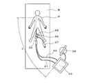
- FIG. 1 is a schematic configuration diagram showing an embodiment of a vascular endoscope system according to the present invention.
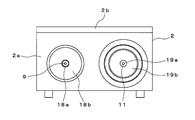
- FIG. 2 is a plan view showing the repeater and the imaging / light source controller of FIG.
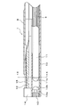
- FIG. 3 is a side view showing the repeater of FIG. 4 is a longitudinal sectional view showing the vascular endoscope catheter of FIG.
- FIG. 5 is a plan view of FIG. 6 is a cross-sectional view taken along line XX of FIG.
- FIG. 7 is a plan view showing another embodiment of the constant speed moving device.
- FIG. 8 is a longitudinal sectional view of a main part showing another embodiment of the vascular endoscope catheter.
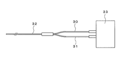
- FIG. 9 is a schematic configuration diagram showing a conventional blood vessel endoscope system.
- 10A is a plan view showing the vascular endoscopic catheter of FIG.
- FIG. 10B is a plan view showing a connection form between the vascular endoscope catheter and the imaging / light source controller.
- this vascular endoscope system includes a vascular endoscope catheter 1, a relay 2 disposed on the surgical bed B and connected to the proximal end portion of the vascular endoscope catheter 1, An imaging / light source controller 4 disposed in the vicinity of the surgical bed B and connected to the repeater 2 via the cable 3; a monitor 5 connected to the imaging / light source controller 4 to display an intravascular image;
- the blood removal liquid injection device 6 for injecting the blood removal liquid and a control device 7 for controlling the injection amount of the blood removal liquid by the blood removal liquid injection device 6 are schematically configured.
- the vascular endoscope catheter 1 has a total length of 1800 mm to 2000 mm, an insertion portion length of 1600 to 1800 mm, and an outer diameter of 0.70 to 1.00 mm. As shown in FIGS. In an outer tube 8 made of stainless steel, an illumination fiber 9 for irradiating light from the tip to an observation site in the blood vessel, and an objective lens 10 for obtaining an intravascular image of the observation site at the tip are used for image transmission. The fiber 11 and the fine pressure sensor 12 are incorporated.
- the image transmission fiber 11 is made of a multicomponent glass fiber having a maximum diameter of 0.3 to 0.5 mm and having 10,000 pixels or more, and is a small-diameter stainless steel objective pipe provided inside the exterior pipe 8. 13 is inserted.
- the objective lens 10 is disposed at the tip of the objective pipe 13.
- the objective lens 10 is made of borosilicate glass in the present embodiment, and a spherical convex lens 10b is formed on the rear end side via a diaphragm 10a.
- a spherical convex lens 11b facing the convex lens 10b is fixed to the tip of the image transmission fiber 11 facing the convex lens 10b.
- a plurality of illumination fibers 9 are disposed on both sides of the objective pipe 13 in the outer pipe 8, and the outer periphery of the distal end portion of the outer pipe 8 facing the objective pipe 13 is cut into a strip shape.
- the fine pressure sensor 12 attached to the pressure sensor holder 14 is disposed in the notched portion.
- reference numeral 15 denotes a silicone waterproof coating that covers the notch.
- an illumination fiber 9, an image transmission fiber 11, and a signal cable (not shown) of the fine pressure sensor 12 drawn from the exterior pipe 8 are provided. It is introduced into the repeater 2.
- the repeater 2 has a rectangular box shape in which the upper opening of the main body 2a is closed by the lid 2b, and the height and width are mounted on the operation bed B. It is formed to be 50 to 200 mm that can be placed. Then, on the side surface of the repeater 2, the illumination fiber 9 and the image transmission are respectively transmitted via the light guide plug 18a, the LG plug fixing portion 18b, the image guide plug 19a, and the IG plug fixing portion 19b arranged in parallel. A fiber 11 is introduced inside.
- a pair of LEDs 20 serving as a light source is disposed at a position facing the proximal end portion of the illumination fiber 9. Further, on the opposite side of the LED 20 across the partition plate 21, a camera head (imaging device) incorporating a lens unit 22 for capturing an image transmitted by the image transmission fiber 11 and digitally converting it, and an imaging device. Part) 23 is arranged.
- the repeater 2 is mounted on a constant speed moving device 24 that moves the repeater 2 at a constant speed in the direction of pulling out the vascular endoscope catheter 1 by a linear stepping motor.
- the power cable and the communication cable of the LED 20 and the camera head 23 are connected to the imaging / light source controller 4 that is bundled with the cable 3 and arranged in the vicinity of the surgical bed B.
- the imaging / light source controller 4 includes a digital recorder that records an intravascular image transmitted from the camera head 23, and a calculation means that calculates the length of the observation site from the moving speed and moving time of the repeater 2. Is provided.
- the blood removing liquid injection device 6 is connected to a Y-shaped connector 36 for connecting the blood vessel endoscope catheter 1 in the outer cylinder and supplying blood removing liquid into the blood vessel instead of the conventional syringe. ing.
- the blood removal liquid injection device 6 is provided with the control device 7 that controls the injection amount of the blood removal liquid by the blood removal liquid injection device 6 in accordance with the movement amount of the relay 2.
- control device 7 injects the blood removal liquid by the blood removal liquid injection device 6 in accordance with the magnitude of the pressure detected by the fine pressure sensor 12 provided at the distal end portion of the vascular endoscope catheter 1. A sequence to control the amount is incorporated.
- the repeater 2 is mounted on the constant speed moving device 24 using a linear stepping motor as a drive source, so that it can move in the direction in which the vascular endoscope catheter 1 is pulled out at a constant speed.
- the present invention is not limited to this.
- a pair of rollers 25a and 25b sandwiching the cable 3 from the repeater 3 is provided. It is also possible to use a constant speed moving device 25 that drives the motor 25b at a constant rotation by a motor.
- the two convex lenses 10b and 11b shown in FIG. 4 are opposed to each other in the light transmission mode between the objective lens 10 and the image transmission fiber 11 at the distal end portion of the objective pipe 13 of the vascular endoscope catheter 1. It is not limited to the configuration.
- a spherical convex lens 10b is formed on the rear end side of the objective lens 10 via a diaphragm 10a, and a double-sided concave lens 26 is disposed adjacent to the convex lens 10b.
- the concave / convex lens 27 may be disposed between the concave lens 26 and the convex lens 11b on the image transmission fiber 11 side so that the concave or convex portions are opposed to each other.
- the small repeater 2 that can be disposed on the surgical bed B is provided between the vascular endoscope catheter 1 and the imaging / light source controller 4.
- the imaging / light source controller 4 Provided to the camera head 23 provided with the LED (light source) 20 and the image sensor provided in the repeater 2 are connected to the proximal ends of the illumination fiber 9 and the image transmission fiber 11, respectively, and the repeater 2 and the image pickup device. Since the light source controller 4 is connected by the cable 3, the length required for the image transmission fiber 11 can be 1800 mm to 2000 mm. As a result, a multicomponent glass fiber capable of obtaining a clear image can be used as the image transmission fiber 11.
- the repeater 2 is movably provided on the constant speed moving device 24 so that the constant speed moving device 24 moves at a constant speed in the direction in which the vascular endoscope catheter 1 is pulled out. Since the amount of blood removal fluid injected by the blood removal fluid injection device 6 can be controlled in accordance with the amount of movement of the repeater 2, it is possible to perform stable quantitative measurement and evaluation without the need for learning. become.
- the imaging / light source controller 4 has calculation means for calculating the length of the observation region from the moving speed and the movement time of the repeater 2, for example, the passage time of the observation region is 2 seconds.
- the moving speed of the repeater 2 is 20 mm / second, it can be easily grasped that the length dimension of the observation site is 40 mm.
- the fine pressure sensor 12 is provided at the distal end portion of the vascular endoscope catheter 1, the pressure at the observation site is detected without introducing a pressure sensor for measuring the pressure in the blood vessel separately. Furthermore, it becomes possible to control the injection amount of the blood removal liquid by the control device 7 in accordance with the magnitude of the pressure detected by the pressure sensor.
- a blood vessel endoscope catheter As an example of the length dimension 1, the insertion part length is 1600 to 1800 mm and the total length is 1800 mm to 2000 mm.
- the present invention is not limited to this, and the sex, age, and the like of the patient P Depending on the difference in the insertion site of the vascular endoscope catheter 1, for example, it may be formed to be about 2500 mm, or may be formed to be 1800 mm or less.
- vascular endoscope system that can observe or measure the nature, length, stenosis, etc. of a lesion in a blood vessel with a clear image.
Landscapes
- Health & Medical Sciences (AREA)
- Life Sciences & Earth Sciences (AREA)
- Surgery (AREA)
- Nuclear Medicine, Radiotherapy & Molecular Imaging (AREA)
- Biomedical Technology (AREA)
- Optics & Photonics (AREA)
- Pathology (AREA)
- Radiology & Medical Imaging (AREA)
- Biophysics (AREA)
- Engineering & Computer Science (AREA)
- Physics & Mathematics (AREA)
- Heart & Thoracic Surgery (AREA)
- Medical Informatics (AREA)
- Molecular Biology (AREA)
- Animal Behavior & Ethology (AREA)
- General Health & Medical Sciences (AREA)
- Public Health (AREA)
- Veterinary Medicine (AREA)
- Endoscopes (AREA)
Abstract
鮮明な画像によって血管内部における病変部の性状、長さ、狭窄度等を観察あるいは計測することが可能になる血管内視鏡システムを提供する。本発明によれば、先端部から血管内の観察部位に光を照射する照明用ファイバー(9)および先端部に観察部位の血管内画像を得るための対物レンズを備える画像伝送用ファイバー(11)が組み込まれた血管内視鏡カテーテル(1)と、撮像素子部が設けられて画像伝送用ファイバーの基端部が接続されるとともに血管内視鏡カテーテル(1)を引き抜く方向に移動自在に設けられた中継器(2)と、中継器(2)とケーブル(3)を介して接続された撮像・光源コントローラー(4)とを備え、かつ上記画像伝送用ファイバー(11)として、多成分ガラスファイバーを用いた。
Description
本発明は、冠動脈等の血管内部における病変部の性状、長さ、狭窄度等を観察あるいは計測するための血管内視鏡システムに関するものである。
図9および図10Aと図10Bは、従来の血流維持型の血管内視鏡システムを示すものである。
この血管内視鏡システムは、先端部から血管内の観察部位に光を照射する照明用ファイバー30および先端部に上記観察部位の血管内画像を得るための対物レンズを備える画像伝送用ファイバー31が組み込まれた血管内視鏡カテーテル32と、これら照明用ファイバー30および画像伝送用ファイバー31の基端部が接続された撮像・光源コントローラー33と、この撮像・光源コントローラー33に接続されて血管内撮影画像を表示するモニタ34とを備えたものである。
この血管内視鏡システムは、先端部から血管内の観察部位に光を照射する照明用ファイバー30および先端部に上記観察部位の血管内画像を得るための対物レンズを備える画像伝送用ファイバー31が組み込まれた血管内視鏡カテーテル32と、これら照明用ファイバー30および画像伝送用ファイバー31の基端部が接続された撮像・光源コントローラー33と、この撮像・光源コントローラー33に接続されて血管内撮影画像を表示するモニタ34とを備えたものである。
上記構成を備えた血管内視鏡システムは、先ず患者Pの大腿部から心臓を取り巻く冠動脈の観察部位まで導入したガイドワイヤーに沿ってガイドカテーテルを挿入し、次いで当該ガイドカテーテル内にY字コネクタ35を介して外筒を挿入した後に、当該外筒内にY字コネクタ36を介して上記血管内視鏡カテーテル32を上記観察部位まで挿入することによって使用に供されるものである。
上記血管内視鏡システムによって、冠動脈の観察部位の観測を行うには、予め血管内視鏡カテーテル32を、その先端部が外筒の先端開口から僅かに後退した位置に配置して外筒に固定し、これらの先端部を、血管内の病変部を通過した位置に配置して、Y字コネクタ36に接続されたシリンジ37から血液除去液を供給して外筒先端側の血管内の血液を除去しつつ、外筒および血管内視鏡カテーテル32を上記病変部に向けて血管から引き抜く方向に徐々に移動させる。
そして、これと併行して、撮像・光源コントローラー33から照明用ファイバー30を介して血管内に光を照射するとともに、これよって対物レンズが取得した画像を、画像伝送用ファイバー31から撮像・光源コントローラー33に送り、この撮像・光源コントローラー33に配置された撮像素子部でデジタルデータに変換してモニタ34に表示させることにより、上記病変部の前後の血管内における状態を観察する。
ところで、このような従来の血管内視鏡システムにおいては、血管内視鏡カテーテル32の全長Lが、患者P内への挿入部長1600~1800mmに手術ベッドBの近傍に配置された撮像・光源コントローラー33までの長さ寸法を加えた約3500mmと長く、かつ挿入部の外径が0.75mm程度と細いものである。このため、一般に画像伝送用ファイバー31としては、光通信ケーブルで使用される透過率に優れた石英ガラスイメージガイド(以下、IGと略す。)が採用されている。
しかしながら、上記石英ガラスIGは、クラッドを構成する石英ガラス内に、コアとなる多数本の画素ファイバーを埋め込んだものであって、隣接した画素ファイバーが上記クラッドを共有する構造であるために、隣接した画素ファイバーの表面波が両画素ファイバー間で混じってしまう現象(クロストーク)が生じてしまう。
この結果、上記クロストークの量が増すと、画像が滲んで色調が単調になったり、あるいは光のモード変化によって着色が生じたりする等、モニタ34に表示される画像に問題が生じるという問題点があった。
一方、消化器領域等に使用される全長が比較的短い内視鏡においては、画像伝送用ファイバーとして多成分ガラスIGが用いられている。この多成分ガラスIGは、クラッドによって被覆されることによって独立した多数本のコアファイバーを、俵積みにして束ねたものであり、石英ガラスIGよりも立体的な画像が得られることが知られている。
ところが、上記多成分ガラスIGは、石英ガラスIGよりも透過率が劣るために、これによって全長が3500mmもの画像伝送用ファイバー31を製造すると、光伝送の過程で青色成分が外部に拡散して黄色味が強い画像となる特性を有しており、このため例えば易破綻性プラークの判断が黄色味によって評価されていることもあって採用することができなかった。
加えて、多成分ガラスIGを用いて全長の長い画像伝送用ファイバーを製造しようとすると、光伝送不良の確立が高くなって製造歩留りが低下するために、製造コストの高騰化を招来するという問題点もあった。
本発明は、上記事情に鑑みてなされたもので、従来よりも鮮明な画像によって血管内部における病変部の性状、長さ、狭窄度等を観察あるいは計測することが可能になる血管内視鏡システムを提供することを課題とするものである。
上記課題を解決するため、請求項1に記載の本発明に係る血管内視鏡システムは、先端部から血管内の観察部位に光を照射する照明用ファイバーおよび先端部に上記観察部位の血管内画像を得るための対物レンズを備える画像伝送用ファイバーが組み込まれた血管内視鏡カテーテルと、少なくとも撮像素子部が設けられて上記画像伝送用ファイバーの基端部が接続されるとともに上記血管内視鏡カテーテルを引き抜く方向に移動自在に設けられた中継器と、この中継器とケーブルを介して接続された撮像・光源コントローラーと、この撮像・光源コントローラーに接続されて血管内撮影画像を表示するモニタとを備えてなり、かつ上記画像伝送用ファイバーは、多成分ガラスファイバーからなることを特徴とするものである。
請求項2に記載の発明は、請求項1に記載の発明において、上記画像伝送用ファイバーは、2000mm以下の長さ寸法であることを特徴とするものであり、請求項3に記載の発明は、請求項1または2に記載の発明において、上記照明用ファイバーの光源が、上記中継器に設けられていることを特徴とするものである。
請求項4に記載の発明は、請求項1~3のいずれかに記載の発明において、上記血管内視鏡カテーテルは外筒内にY字コネクタを介して挿入され、上記Y字コネクタには上記外筒と上記血管内視鏡カテーテルとの間から上記観察部位に血液除去液を注入する血液除去液注入装置が接続されているとともに、上記血管内視鏡カテーテルを引き抜く方向に上記中継器を定速で移動させる定速移動装置と、この定速移動装置による上記中継器の移動量と上記血液除去液の注入量とを制御する制御装置を備えていることを特徴とするものである。
請求項5に記載の発明は、請求項4に記載の発明において、上記撮像・光源コントローラーは、上記血管内画像を記録するデジタルレコーダーと、上記中継器の移動速度と移動時間とから上記観察部位の長さを算出する演算手段とを備えていることを特徴とするものである。
請求項6に記載の発明は、請求項1~5のいずれかに記載の発明において、上記対物レンズと上記画像伝送用ファイバーとの間に、上記対物レンズからの光を上記画像伝送用ファイバーに入射させる2以上の球面または非球面の凸レンズが配置されていることを特徴とするものである。
請求項7に記載の発明は、請求項1~6のいずれかに記載の発明において、上記血管内視鏡カテーテルの先端部外周に、圧力センサーが設置されていることを特徴とするものである。
請求項8に記載の発明は、請求項7に記載の発明において、上記制御装置は、上記圧力センサーが検知した圧力の大きさに対応して上記血液除去液注入装置による上記血液除去液の注入量を制御することを特徴とするものである。
本発明者等による検証によれば、多成分ガラスファイバーを用いた場合にも、その全長が2500mm以下であれば、光伝送の過程で青色成分が外部に拡散して黄色味が強い画像となる現象が実用上問題となるほどに生じることが無く、さらに2000mm以下であれば、上記現象がほとんど顕在化しないことが判明している。
そして、請求項1~8のいずれかに記載の発明によれば、血管内視鏡カテーテルと撮像・光源コントローラーとの間に、少なくとも撮像素子部が設けられた中継器を上記血管内視鏡カテーテルを引き抜く方向に移動自在に設け、この中継器に上記画像伝送用ファイバーの基端部を接続するとともに、中継器と撮像・光源コントローラーとをケーブルで接続しているために、中継器を例えば手術ベッド上に配置することにより、上記画像伝送用ファイバーの長さ寸法を、容易に上述した2500mm以下、好ましくは請求項2に記載の発明のように2000mm以下に設定することができる。この結果、上記画像伝送用ファイバーとして、多成分ガラスファイバーを用いることにより、従来よりも鮮明な画像を得ることが可能になる。
ちなみに、本発明においては、画像伝送用ファイバーの長さ寸法を小さくすることを主眼としているために、中継器は少なくとも画像伝送用ファイバーを接続するための撮像素子部が設けられていればよいが、請求項3に記載の発明のように、照明用ファイバーの光源を設け、上記画像伝送用ファイバーと照明用ファイバーの両者を中継器に接続するようにしてもよい。
また、図9に示した従来の血管内視鏡システムを用いた検査においては、病変部の前後の長い観察部位の画像を得るために、術者がガイドカテーテル内の外筒を血管内視鏡カテーテルを引く作業(プルバック操作)と併行して、補助者が手動でシリンジから血液除去液を注入する操作(フラッシュ操作)を行い、継続的に画像が得られるようにモニタを注視しながら2名で連携して調整および上記操作を行っていた。
このため、術者と補助者は、連携トレーニング等によって上記操作に習熟しておく必要があり、その手技の煩雑さにより術式普及の障害となっていた。しかも、上記プルバック操作およびフラッシュ操作は、いずれも手動で行われているために、一定の速度を保持することが難しく、よって患部病変の大きさを計測評価することができないために、定量性に欠けるという問題点があった。
これに対して、請求項4に記載の発明によれば、定速移動装置によって血管内視鏡カテーテルを一定の速度で引き抜くとともに、制御装置によって上記定速移動装置による中継器の移動量に対応させて血液除去液注入装置による血液除去液の注入量を制御することができ、さらに請求項5に記載の発明によれば、上記中継器の移動速度と移動時間とから上記観察部位の長さを算出することができるために、習熟を要することなく安定して定量的な計測評価を行うことが可能になる。
また、請求項6に記載の発明によれば、一般的なロッドレンズと画像伝送用ファイバーとを突き合わせた伝送形態と比較して、より解像度の高い画像を得ることができる。
加えて、請求項7に記載の発明によれば、上記血管内視鏡カテーテルに代えて別途血管内の圧力を計測するための圧力センサーを導入することなく、血管内視鏡カテーテルの先端部外周に設けた圧力センサーによって上記観測部位における圧力を検知することができる。このため、請求項8に記載の発明によれば、上記制御装置によって上記圧力センサーが検知した圧力の大きさに対応して血液除去液の注入量を制御することも可能になる。
図1~図6は、本発明に係る血管内視鏡システムの一実施形態を示すものである。なお、図9に示したものと同一構成部分については、同一符号を付してその説明を省略する。
図1に示すように、この血管内視鏡システムは、血管内視鏡カテーテル1と、手術ベッドB上に配置されて血管内視鏡カテーテル1の基端部が接続された中継器2と、手術ベッドBの近傍に配置されるとともに中継器2とケーブル3を介して接続された撮像・光源コントローラー4と、この撮像・光源コントローラー4に接続されて血管内撮影画像を表示するモニタ5と、血液除去液を注入するための血液除去液注入装置6と、この血液除去液注入装置6による血液除去液の注入量を制御する制御装置7とから概略構成されたものである。
図1に示すように、この血管内視鏡システムは、血管内視鏡カテーテル1と、手術ベッドB上に配置されて血管内視鏡カテーテル1の基端部が接続された中継器2と、手術ベッドBの近傍に配置されるとともに中継器2とケーブル3を介して接続された撮像・光源コントローラー4と、この撮像・光源コントローラー4に接続されて血管内撮影画像を表示するモニタ5と、血液除去液を注入するための血液除去液注入装置6と、この血液除去液注入装置6による血液除去液の注入量を制御する制御装置7とから概略構成されたものである。
上記血管内視鏡カテーテル1は、全長が1800mm~2000mm、挿入部分長が1600~1800mm、外径が0.70~1.00mmのもので、図4~図6に示すように、挿入部分となるステンレス製の外装パイプ8内に、先端部から血管内の観察部位に光を照射する照明用ファイバー9、先端部に観察部位の血管内画像を得るための対物レンズ10を備えた画像伝送用ファイバー11および微細圧力センサー12が組み込まれたものである。
この画像伝送用ファイバー11は、最大径が0.3~0.5mmである1万画素以上の多成分ガラスファイバーからなるもので、外装パイプ8の内部に設けられた小径のステンレス製の対物パイプ13内に挿入されている。そして、この対物パイプ13の先端部に、上記対物レンズ10が配置されている。
この対物レンズ10は、本実施形態においてはホウ珪酸ガラスからなるもので、後端側には、絞り部10aを介して球面の凸レンズ10bが形成されている。他方、この凸レンズ10bと対向する画像伝送用ファイバー11の先端部には、上記凸レンズ10bと対向する球面の凸レンズ11bが固定されている。
そして、外装パイプ8内における対物パイプ13の両側に、それぞれ複数本の照明用ファイバー9が配置されるとともに、対物パイプ13と対向する外装パイプ8の先端部外周が帯状に切り欠かれ、この切欠き部分に、圧力センサーホルダ14に取り付けられた上記微細圧力センサー12が配置されている。なお、図中符号15は、上記切欠き部分を覆うシリコン防水コーティングを示すものである。
他方、この血管内視鏡カテーテル1の基端部側においては、外装パイプ8から引き出された照明用ファイバー9、画像伝送用ファイバー11および微細圧力センサー12の信号ケーブル(図示を略す。)が、上記中継器2に導入されている。
この中継器2は、図2および図3に示すように、本体2aの上部開口が蓋体2bによって塞がれた方形の箱状のもので、縦横高さの寸法が手術ベッドB上に載置可能な50~200mmに形成されている。そして、この中継器2の側面に、並列的に配置されたライトガイドプラグ18a、LGプラグ固定部18bおよびイメージガイドプラグ19a、IGプラグ固定部19bを介して、各々照明用ファイバー9および画像伝送用ファイバー11が内部に導入されている。
この中継器2の本体2a内には、照明用ファイバー9の基端部に臨む位置に、光源となる一対のLED20が配置されている。また、これらLED20に対して仕切り板21を隔てた反対側には、画像伝送用ファイバー11によって伝送された画像を取り込んでデジタル変換するためのレンズユニット22および撮像素子を組み込んだカメラヘッド(撮像素子部)23が配置されている。
そして、この中継器2は、リニアステッピングモータによって当該中継器2を一定の速度で血管内視鏡カテーテル1を引き抜く方向に移動させる定速移動装置24上に載置されている。
また、LED20およびカメラヘッド23の電源ケーブルおよび通信ケーブルは、ケーブル3に束ねられて手術ベッドBの近傍に配置されている撮像・光源コントローラー4に接続されている。ちなみに、この撮像・光源コントローラー4は、カメラヘッド23から伝送されてくる血管内画像を記録するデジタルレコーダーと、中継器2の移動速度と移動時間とから上記観察部位の長さを算出する演算手段が備えられている。
他方、外筒内に血管内視鏡カテーテル1を接続するとともに血管内に血液除去液を供給するためのY字コネクタ36には、従来のシリンジに代えて上記血液除去液注入装置6が接続されている。そして、この血液除去液注入装置6には、中継器2の移動量に対応して血液除去液注入装置6による血液除去液の注入量を制御する上記制御装置7が設けられている。
さらに、この制御装置7には、血管内視鏡カテーテル1の先端部に設けられた微細圧力センサー12が検知した圧力の大きさに対応して、血液除去液注入装置6による血液除去液の注入量を制御するシークエンスが組み込まれている。
なお、上記実施形態においては、中継器2を、リニアステッピングモータを駆動源とする定速移動装置24上に載置することにより、一定の速度で血管内視鏡カテーテル1を引き抜く方向に移動自在に設けた場合についてのみ説明したが、これに限定されるものではなく、例えば図7に示すように、中継器3からのケーブル3を間に挟む一対のローラ25a、25bを備え、一方のローラ25bをモータによって一定回転で駆動させる定速移動装置25等を用いることもできる。
また、血管内視鏡カテーテル1の対物パイプ13の先端部における対物レンズ10と画像伝送用ファイバー11との間の光の伝送形態についても、図4に示した2つの凸レンズ10b、11bを対向する構成に限るものではない。例えば、図8に示すように、対物レンズ10の後端側に絞り部10aを介して球面の凸レンズ10bを形成し、この凸レンズ10bに隣接して両面凹レンズ26を配置するとともに、さらにこの両面凹レンズ26と画像伝送用ファイバー11側の凸レンズ11bとの間に、凹凸レンズ27を互いの凹または凸を対向させて配置するようにしてもよい。
以上説明したように、上記構成からなる血管内視鏡システムによれば、血管内視鏡カテーテル1と撮像・光源コントローラー4との間に、手術ベッドB上に配置可能な小型の中継器2を設け、この中継器2に設けたLED(光源)20および撮像素子を備えたカメラヘッド23に、それぞれ照明用ファイバー9および画像伝送用ファイバー11の基端部を接続するとともに、中継器2と撮像・光源コントローラー4とをケーブル3で接続しているために、画像伝送用ファイバー11として必要な長さ寸法を1800mm~2000mmにすることができる。この結果、上記画像伝送用ファイバー11として、鮮明な画像が得られる多成分ガラスファイバーを用いることができる。
また、上記中継器2を定速移動装置24上に移動自在に設け、この定速移動装置24によって血管内視鏡カテーテル1を引き抜く方向に一定速度で移動するようにするとともに、制御装置7によって中継器2の移動量に対応させて血液除去液注入装置6による血液除去液の注入量を制御することができるために、習熟を要することなく安定して定量的な計測評価を行うことが可能になる。
加えて、撮像・光源コントローラー4は、中継器2の移動速度と移動時間とから観察部位の長さを算出する演算手段を有しているために、例えば観察部位の通過時間が2秒であって、中継器2の移動速度が20mm/秒であった場合に、上記観察部位の長さ寸法が40mmであったことを容易に把握することができる。
このため、この撮像・光源コントローラー4のデジタルレコーダーが記録したカメラヘッド23から伝送されてくる血管内画像と対比することにより、確実に病変部の長さ寸法を計測することが可能になる。
また、血管内視鏡カテーテル1の先端部に、微細圧力センサー12を設けているために、別途血管内の圧力を計測するための圧力センサーを導入することなく、上記観測部位における圧力を検知することができ、さらには上記圧力センサーが検知した圧力の大きさに対応して制御装置7により血液除去液の注入量を制御することも可能になる。
なお、上記実施形態は、上記血管内視鏡カテーテル1を患者Pの大腿部から心臓を取り巻く冠動脈の観察部位まで挿入するものに適用した場合について説明しているために、血管内視鏡カテーテル1の長さ寸法として、挿入部分長が1600~1800mmであって、全長が1800mm~2000mmの場合を例示したが、本発明はこれに限定されるものではなく、患者Pの性別、年齢や上記血管内視鏡カテーテル1の挿入部位の相違によっては、例えば2500mm程度に形成したり、あるいは1800mm以下に形成したりする場合も含むものである。
鮮明な画像によって血管内部における病変部の性状、長さ、狭窄度等を観察あるいは計測することが可能になる血管内視鏡システムを提供することができる。
1 血管内視鏡カテーテル
2 中継器
3 ケーブル
4 撮像・光源コントローラー
5 モニタ
6 血液除去液注入装置
7 制御装置
9 照明用ファイバー
10 対物レンズ
11 画像伝送用ファイバー
10b、11b 凸レンズ
12 微細圧力センサー(圧力センサー)
20 LED(光源)
23 カメラヘッド(撮像素子部)
24、25 定速移動装置24
36 Y字コネクタ
2 中継器
3 ケーブル
4 撮像・光源コントローラー
5 モニタ
6 血液除去液注入装置
7 制御装置
9 照明用ファイバー
10 対物レンズ
11 画像伝送用ファイバー
10b、11b 凸レンズ
12 微細圧力センサー(圧力センサー)
20 LED(光源)
23 カメラヘッド(撮像素子部)
24、25 定速移動装置24
36 Y字コネクタ
Claims (8)
- 先端部から血管内の観察部位に光を照射する照明用ファイバーおよび先端部に上記観察部位の血管内画像を得るための対物レンズを備える画像伝送用ファイバーが組み込まれた血管内視鏡カテーテルと、少なくとも撮像素子部が設けられて上記画像伝送用ファイバーの基端部が接続されるとともに上記血管内視鏡カテーテルを引き抜く方向に移動自在に設けられた中継器と、この中継器とケーブルを介して接続された撮像・光源コントローラーと、この撮像・光源コントローラーに接続されて血管内撮影画像を表示するモニタとを備えてなり、
かつ上記画像伝送用ファイバーは、多成分ガラスファイバーからなることを特徴とする血管内視鏡システム。 - 上記画像伝送用ファイバーは、2000mm以下の長さ寸法であることを特徴とする請求項1に記載の血管内視鏡システム。
- 上記照明用ファイバーの光源は、上記中継器に設けられていることを特徴とする請求項1または2に記載の血管内視鏡システム。
- 上記血管内視鏡カテーテルは外筒内にY字コネクタまたはT字コネクタを介して挿入され、上記Y字コネクタまたはT字コネクタには、上記外筒と上記血管内視鏡カテーテルとの間から上記観察部位に血液除去液を注入する血液除去液注入装置が接続されているとともに、
上記血管内視鏡カテーテルを引き抜く方向に上記中継器を定速で移動させる定速移動装置と、この定速移動装置による上記中継器の移動量と上記血液除去液の注入量とを制御する制御装置を備えていることを特徴とする請求項1ないし3のいずれかに記載の血管内視鏡システム。 - 上記撮像・光源コントローラーは、上記血管内画像を記録するデジタルレコーダーと、上記中継器の移動速度と移動時間とから上記観察部位の長さを算出する演算手段とを備えていることを特徴とする請求項4に記載の血管内視鏡システム。
- 上記対物レンズと上記画像伝送用ファイバーとの間に、上記対物レンズからの光を上記画像伝送用ファイバーに入射させる2以上の球面または非球面の凸レンズが配置されていることを特徴とする請求項1ないし5のいずれかに記載の血管内視鏡システム。
- 上記血管内視鏡カテーテルの先端部外周に、圧力センサーが設置されていることを特徴とする請求項1ないし6のいずれかに記載の血管内視鏡システム。
- 上記制御装置は、上記圧力センサーが検知した圧力の大きさに対応して上記血液除去液注入装置による上記血液除去液の注入量を制御することを特徴とする請求項7に記載の血管内視鏡システム。
Applications Claiming Priority (2)
| Application Number | Priority Date | Filing Date | Title |
|---|---|---|---|
| JP2014095061A JP6342210B2 (ja) | 2014-05-02 | 2014-05-02 | 血管内視鏡システム |
| JP2014-095061 | 2014-05-02 |
Publications (1)
| Publication Number | Publication Date |
|---|---|
| WO2015166648A1 true WO2015166648A1 (ja) | 2015-11-05 |
Family
ID=54358393
Family Applications (1)
| Application Number | Title | Priority Date | Filing Date |
|---|---|---|---|
| PCT/JP2015/002180 Ceased WO2015166648A1 (ja) | 2014-05-02 | 2015-04-22 | 血管内視鏡システム |
Country Status (2)
| Country | Link |
|---|---|
| JP (1) | JP6342210B2 (ja) |
| WO (1) | WO2015166648A1 (ja) |
Cited By (3)
| Publication number | Priority date | Publication date | Assignee | Title |
|---|---|---|---|---|
| CN110446450A (zh) * | 2017-03-17 | 2019-11-12 | 国立大学法人大阪大学 | 软性内窥镜和具有该软性内窥镜的内窥镜系统 |
| CN112190225A (zh) * | 2020-11-04 | 2021-01-08 | 上海睿触科技有限公司 | 一种血管内窥镜 |
| CN113243899A (zh) * | 2021-06-11 | 2021-08-13 | 北京市神经外科研究所 | 一种血管内压力测量导管 |
Families Citing this family (2)
| Publication number | Priority date | Publication date | Assignee | Title |
|---|---|---|---|---|
| JP6284110B1 (ja) * | 2017-03-03 | 2018-02-28 | 国立大学法人大阪大学 | 軟性内視鏡と接続可能な中継器装置、およびそれを用いた内視鏡システム |
| JP6284111B1 (ja) * | 2017-03-03 | 2018-02-28 | 国立大学法人大阪大学 | 軟性内視鏡と中継器装置との接続構造、およびそれを備える内視鏡システム |
Citations (3)
| Publication number | Priority date | Publication date | Assignee | Title |
|---|---|---|---|---|
| JPH0424017A (ja) * | 1990-05-21 | 1992-01-28 | Olympus Optical Co Ltd | 磁気誘導式挿入具 |
| JPH06202007A (ja) * | 1992-12-28 | 1994-07-22 | Olympus Optical Co Ltd | 内視鏡観察システム |
| JP2000175917A (ja) * | 1998-12-17 | 2000-06-27 | Terumo Corp | 超音波トランスデューサ軸方向移動装置および超音波カテーテル診断装置 |
-
2014
- 2014-05-02 JP JP2014095061A patent/JP6342210B2/ja active Active
-
2015
- 2015-04-22 WO PCT/JP2015/002180 patent/WO2015166648A1/ja not_active Ceased
Patent Citations (3)
| Publication number | Priority date | Publication date | Assignee | Title |
|---|---|---|---|---|
| JPH0424017A (ja) * | 1990-05-21 | 1992-01-28 | Olympus Optical Co Ltd | 磁気誘導式挿入具 |
| JPH06202007A (ja) * | 1992-12-28 | 1994-07-22 | Olympus Optical Co Ltd | 内視鏡観察システム |
| JP2000175917A (ja) * | 1998-12-17 | 2000-06-27 | Terumo Corp | 超音波トランスデューサ軸方向移動装置および超音波カテーテル診断装置 |
Cited By (4)
| Publication number | Priority date | Publication date | Assignee | Title |
|---|---|---|---|---|
| CN110446450A (zh) * | 2017-03-17 | 2019-11-12 | 国立大学法人大阪大学 | 软性内窥镜和具有该软性内窥镜的内窥镜系统 |
| CN110446450B (zh) * | 2017-03-17 | 2021-10-01 | 国立大学法人大阪大学 | 软性内窥镜和具有该软性内窥镜的内窥镜系统 |
| CN112190225A (zh) * | 2020-11-04 | 2021-01-08 | 上海睿触科技有限公司 | 一种血管内窥镜 |
| CN113243899A (zh) * | 2021-06-11 | 2021-08-13 | 北京市神经外科研究所 | 一种血管内压力测量导管 |
Also Published As
| Publication number | Publication date |
|---|---|
| JP6342210B2 (ja) | 2018-06-13 |
| JP2015211739A (ja) | 2015-11-26 |
Similar Documents
| Publication | Publication Date | Title |
|---|---|---|
| US9872613B2 (en) | Monitoring disposition of tethered capsule endoscope in esophagus | |
| US11259702B2 (en) | Fiber optic imaging probe having cladding mode pullback trigger, and control method therefor | |
| Lee et al. | Scanning fiber endoscopy with highly flexible, 1 mm catheterscopes for wide‐field, full‐color imaging | |
| EP2198775B1 (en) | Optical structure observation apparatus and structure information processing method of the same | |
| US20130211246A1 (en) | METHODS AND DEVICES FOR GASTROINTESTINAL SURGICAL PROCEDURES USING NEAR INFRARED (nIR) IMAGING TECHNIQUES | |
| JP6342210B2 (ja) | 血管内視鏡システム | |
| US20110077463A1 (en) | Optical probe and endoscope apparatus | |
| US12161295B2 (en) | Deep brain stimulation electrode with photoacoustic and ultrasound imaging capabilities | |
| KR20230048344A (ko) | 가간섭성 광을 내시경 시스템에 커플링하기 위한 디바이스 | |
| US12582472B2 (en) | Systems for determining size of kidney stone | |
| JP5988907B2 (ja) | 内視鏡システム | |
| CN111419149A (zh) | 一种多模态内窥镜及内窥成像系统 | |
| JP2010537771A (ja) | テザー付きカプセル内視鏡の食道内配置の監視 | |
| JP2011078447A (ja) | 光構造観察装置、その構造情報処理方法及び光構造観察装置を備えた内視鏡装置 | |
| JP2009061014A (ja) | 硬さ測定装置、硬さ測定方法、および内視鏡システム | |
| Inoue et al. | Novel endoscopic imaging techniques toward in vivo observation of living cancer cells in the gastrointestinal tract | |
| KR20180134297A (ko) | 광섬유 프로브 및 이를 포함하는 내시경 장치 | |
| JP2011072401A (ja) | 光プローブ及び内視鏡装置 | |
| JP2014057898A (ja) | テザー付きカプセル内視鏡の食道内配置の監視 | |
| CN116138716B (zh) | 成像导管及血管内成像系统 | |
| JP4133013B2 (ja) | Oct観察用プローブ | |
| CN104545776A (zh) | 用于伸入血管的检查镜 | |
| CN203677046U (zh) | 用于伸入血管的检查镜 | |
| Mora | Development of a novel method using optical coherence tomography (OCT) for guidance of robotized interventional endoscopy | |
| JP2022025651A (ja) | 血管観察装置 |
Legal Events
| Date | Code | Title | Description |
|---|---|---|---|
| 121 | Ep: the epo has been informed by wipo that ep was designated in this application |
Ref document number: 15786849 Country of ref document: EP Kind code of ref document: A1 |
|
| NENP | Non-entry into the national phase |
Ref country code: DE |
|
| 122 | Ep: pct application non-entry in european phase |
Ref document number: 15786849 Country of ref document: EP Kind code of ref document: A1 |