WO2015162779A1 - Exhaust gas recirculation control device and exhaust gas recirculation control method - Google Patents

Exhaust gas recirculation control device and exhaust gas recirculation control method Download PDF

Info

Publication number
WO2015162779A1
WO2015162779A1 PCT/JP2014/061706 JP2014061706W WO2015162779A1 WO 2015162779 A1 WO2015162779 A1 WO 2015162779A1 JP 2014061706 W JP2014061706 W JP 2014061706W WO 2015162779 A1 WO2015162779 A1 WO 2015162779A1
Authority
WO
WIPO (PCT)
Prior art keywords
exhaust gas
recirculation
gas recirculation
passage
recirculation control
Prior art date
Application number
PCT/JP2014/061706
Other languages
French (fr)
Japanese (ja)
Inventor
大介 高木
土田 博文
和彦 菅原
Original Assignee
日産自動車株式会社
Priority date (The priority date is an assumption and is not a legal conclusion. Google has not performed a legal analysis and makes no representation as to the accuracy of the date listed.)
Filing date
Publication date
Application filed by 日産自動車株式会社 filed Critical 日産自動車株式会社
Priority to US15/305,518 priority Critical patent/US10100759B2/en
Priority to JP2016514661A priority patent/JP6210153B2/en
Priority to EP14889919.8A priority patent/EP3139026B1/en
Priority to PCT/JP2014/061706 priority patent/WO2015162779A1/en
Priority to CN201480078163.XA priority patent/CN106255819B/en
Publication of WO2015162779A1 publication Critical patent/WO2015162779A1/en

Links

Images

Classifications

    • FMECHANICAL ENGINEERING; LIGHTING; HEATING; WEAPONS; BLASTING
    • F02COMBUSTION ENGINES; HOT-GAS OR COMBUSTION-PRODUCT ENGINE PLANTS
    • F02DCONTROLLING COMBUSTION ENGINES
    • F02D41/00Electrical control of supply of combustible mixture or its constituents
    • F02D41/0025Controlling engines characterised by use of non-liquid fuels, pluralities of fuels, or non-fuel substances added to the combustible mixtures
    • F02D41/0047Controlling exhaust gas recirculation [EGR]
    • F02D41/005Controlling exhaust gas recirculation [EGR] according to engine operating conditions
    • F02D41/0052Feedback control of engine parameters, e.g. for control of air/fuel ratio or intake air amount
    • FMECHANICAL ENGINEERING; LIGHTING; HEATING; WEAPONS; BLASTING
    • F02COMBUSTION ENGINES; HOT-GAS OR COMBUSTION-PRODUCT ENGINE PLANTS
    • F02DCONTROLLING COMBUSTION ENGINES
    • F02D41/00Electrical control of supply of combustible mixture or its constituents
    • F02D41/0002Controlling intake air
    • F02D41/0007Controlling intake air for control of turbo-charged or super-charged engines
    • FMECHANICAL ENGINEERING; LIGHTING; HEATING; WEAPONS; BLASTING
    • F02COMBUSTION ENGINES; HOT-GAS OR COMBUSTION-PRODUCT ENGINE PLANTS
    • F02DCONTROLLING COMBUSTION ENGINES
    • F02D41/00Electrical control of supply of combustible mixture or its constituents
    • F02D41/02Circuit arrangements for generating control signals
    • F02D41/04Introducing corrections for particular operating conditions
    • F02D41/08Introducing corrections for particular operating conditions for idling
    • FMECHANICAL ENGINEERING; LIGHTING; HEATING; WEAPONS; BLASTING
    • F02COMBUSTION ENGINES; HOT-GAS OR COMBUSTION-PRODUCT ENGINE PLANTS
    • F02DCONTROLLING COMBUSTION ENGINES
    • F02D41/00Electrical control of supply of combustible mixture or its constituents
    • F02D41/02Circuit arrangements for generating control signals
    • F02D41/14Introducing closed-loop corrections
    • F02D41/16Introducing closed-loop corrections for idling
    • FMECHANICAL ENGINEERING; LIGHTING; HEATING; WEAPONS; BLASTING
    • F02COMBUSTION ENGINES; HOT-GAS OR COMBUSTION-PRODUCT ENGINE PLANTS
    • F02MSUPPLYING COMBUSTION ENGINES IN GENERAL WITH COMBUSTIBLE MIXTURES OR CONSTITUENTS THEREOF
    • F02M26/00Engine-pertinent apparatus for adding exhaust gases to combustion-air, main fuel or fuel-air mixture, e.g. by exhaust gas recirculation [EGR] systems
    • F02M26/02EGR systems specially adapted for supercharged engines
    • F02M26/04EGR systems specially adapted for supercharged engines with a single turbocharger
    • F02M26/05High pressure loops, i.e. wherein recirculated exhaust gas is taken out from the exhaust system upstream of the turbine and reintroduced into the intake system downstream of the compressor
    • FMECHANICAL ENGINEERING; LIGHTING; HEATING; WEAPONS; BLASTING
    • F02COMBUSTION ENGINES; HOT-GAS OR COMBUSTION-PRODUCT ENGINE PLANTS
    • F02MSUPPLYING COMBUSTION ENGINES IN GENERAL WITH COMBUSTIBLE MIXTURES OR CONSTITUENTS THEREOF
    • F02M26/00Engine-pertinent apparatus for adding exhaust gases to combustion-air, main fuel or fuel-air mixture, e.g. by exhaust gas recirculation [EGR] systems
    • F02M26/02EGR systems specially adapted for supercharged engines
    • F02M26/04EGR systems specially adapted for supercharged engines with a single turbocharger
    • F02M26/06Low pressure loops, i.e. wherein recirculated exhaust gas is taken out from the exhaust downstream of the turbocharger turbine and reintroduced into the intake system upstream of the compressor
    • FMECHANICAL ENGINEERING; LIGHTING; HEATING; WEAPONS; BLASTING
    • F02COMBUSTION ENGINES; HOT-GAS OR COMBUSTION-PRODUCT ENGINE PLANTS
    • F02MSUPPLYING COMBUSTION ENGINES IN GENERAL WITH COMBUSTIBLE MIXTURES OR CONSTITUENTS THEREOF
    • F02M26/00Engine-pertinent apparatus for adding exhaust gases to combustion-air, main fuel or fuel-air mixture, e.g. by exhaust gas recirculation [EGR] systems
    • F02M26/52Systems for actuating EGR valves
    • F02M26/64Systems for actuating EGR valves the EGR valve being operated together with an intake air throttle
    • FMECHANICAL ENGINEERING; LIGHTING; HEATING; WEAPONS; BLASTING
    • F02COMBUSTION ENGINES; HOT-GAS OR COMBUSTION-PRODUCT ENGINE PLANTS
    • F02DCONTROLLING COMBUSTION ENGINES
    • F02D41/00Electrical control of supply of combustible mixture or its constituents
    • F02D41/0002Controlling intake air
    • F02D2041/0017Controlling intake air by simultaneous control of throttle and exhaust gas recirculation
    • YGENERAL TAGGING OF NEW TECHNOLOGICAL DEVELOPMENTS; GENERAL TAGGING OF CROSS-SECTIONAL TECHNOLOGIES SPANNING OVER SEVERAL SECTIONS OF THE IPC; TECHNICAL SUBJECTS COVERED BY FORMER USPC CROSS-REFERENCE ART COLLECTIONS [XRACs] AND DIGESTS
    • Y02TECHNOLOGIES OR APPLICATIONS FOR MITIGATION OR ADAPTATION AGAINST CLIMATE CHANGE
    • Y02TCLIMATE CHANGE MITIGATION TECHNOLOGIES RELATED TO TRANSPORTATION
    • Y02T10/00Road transport of goods or passengers
    • Y02T10/10Internal combustion engine [ICE] based vehicles
    • Y02T10/12Improving ICE efficiencies

Definitions

  • the present invention relates to an exhaust gas recirculation control device and an exhaust gas recirculation control method for an internal combustion engine.
  • EGR exhaust gas recirculation
  • the EGR device includes an EGR passage that branches from the exhaust passage and merges with the intake passage, and an EGR valve that opens and closes the flow path of the EGR passage.
  • the EGR valve opens according to the target EGR rate, and the exhaust
  • the configuration is such that EGR gas flows to the intake side using the differential pressure between the intake side and the intake side.
  • the controller sets a target EGR rate in the operating state of the internal combustion engine, and controls the ignition timing according to the target EGR rate. Therefore, when the amount of EGR gas that actually passes through the EGR valve (actual EGR gas amount) is smaller than the target EGR gas amount, knocking occurs when the engine is operated at the ignition timing corrected on the assumption that the target EGR rate is reached. May occur.
  • the above-described deviation between the target EGR gas amount and the actual EGR gas amount is likely to occur when the differential pressure between the exhaust side and the intake side is small.
  • the pressure loss becomes smaller. For example, when the EGR valve is opened while the exhaust system is cold, the difference between the exhaust side and the intake side is low because the pressure of the exhaust passage is low. The pressure is reduced.
  • the smaller the intake air amount the smaller the exhaust flow rate, making it difficult for the pressure on the exhaust side to increase.
  • the same EGR rate is set regardless of the engine speed if the load is the same without considering the intake air amount. For example, the low rotation and high load region, that is, the load is high. However, in a region where the intake air amount is small, knocking due to the difference between the target EGR gas amount and the actual EGR gas amount is likely to occur.
  • an object of the present invention is to provide an EGR control device that controls the EGR device so that the occurrence of knocking can be suppressed even when the difference between the target EGR rate and the actual EGR rate is likely to occur.
  • the exhaust gas recirculation control device is configured to remove a part of the exhaust gas of the internal combustion engine from the exhaust passage downstream of the turbine of the turbocharger and from the compressor of the turbocharger.
  • An exhaust gas recirculation passage that recirculates to the intake passage upstream of the intake air flow and downstream of the air flow meter, and a recirculation control valve that adjusts the amount of exhaust gas recirculated to the intake air passage.
  • the exhaust gas recirculation control device has a recirculation rate setting means for setting a lower target recirculation rate as the intake air amount of the internal combustion engine is smaller, and controls the opening degree of the recirculation control valve according to the target recirculation rate. To do.
  • FIG. 1 is a configuration diagram of an internal combustion engine system to which the present embodiment is applied.
  • FIG. 2 is a diagram illustrating an example of the target EGR rate map.
  • FIG. 3 is a diagram illustrating an example of a target EGR rate map according to the present embodiment.
  • FIG. 4 is a diagram illustrating another example of the target EGR rate map according to the present embodiment.
  • FIG. 1 is a configuration diagram of an internal combustion engine system to which an embodiment of the present invention is applied.
  • an air flow meter 3 In the intake passage 2 of the internal combustion engine 1, an air flow meter 3, a compressor 4A of the turbocharger 4, a throttle chamber 5, and a collector tank 6 on the intercooler integrated side are arranged from the upstream side of the intake flow.
  • the system includes a recirculation passage 13 that communicates the upstream side and the downstream side of the compressor 4A, and a recirculation valve 14 that opens during deceleration to return intake air from the downstream side to the upstream side of the compressor 4A.
  • the turbine 4B, the manifold catalyst 8, and the underfloor catalyst 9 of the turbocharger 4 are arranged in the exhaust passage 7 from the upstream side of the exhaust flow.
  • the present system includes a bypass passage 15 that communicates the upstream side and the downstream side of the turbine 4B, and a valve 16 that opens and closes the flow path of the bypass passage 15.
  • the manifold catalyst 8 and the underfloor catalyst 9 are both exhaust purification catalyst devices.
  • the manifold catalyst 8 is arranged at a position close to the downstream side of the turbine 4B so that the exhaust gas flows in as high as possible.
  • the underfloor catalyst 9 has a larger capacity than the manifold catalyst 8 and is disposed under the floor of the vehicle.
  • the system also includes an exhaust gas recirculation device (hereinafter also referred to as an “EGR device”).
  • the EGR device branches from between the manifold catalyst 8 and the underfloor catalyst 9 in the exhaust passage 7 and joins the exhaust recirculation passage (hereinafter referred to as “the flow passage 3” upstream of the compressor 4A and downstream of the air flow meter 3 of the intake passage 2).
  • a recirculation valve hereinafter also referred to as “EGR valve” 11 for adjusting the amount of exhaust gas (hereinafter also referred to as “EGR gas”) passing through the EGR passage 10. Consists of.
  • an EGR gas cooler 12 that cools the EGR gas may be included.
  • the EGR device of the present embodiment is a so-called low pressure EGR device that recirculates a part of the exhaust gas from the downstream side of the turbine 4B to the upstream side of the compressor 4A and the downstream side of the air flow meter 3.
  • the internal combustion engine system described above further includes a crank angle sensor 18 that detects the rotational speed of the internal combustion engine 1 (hereinafter also referred to as the engine rotational speed) and an accelerator pedal opening sensor 19, and these sensors and the air flow meter 3. Is detected by the controller 100.
  • the controller 100 executes ignition control, fuel injection control, throttle valve opening control, EGR device control (EGR control), and the like based on the read detection value.
  • EGR control EGR device control
  • the controller 100 first determines the target EGR rate by map search or the like based on the operating state (for example, engine speed and load), and controls the EGR valve 11 to an opening degree corresponding to the target EGR rate. A method for setting the target EGR rate will be described later.
  • the opening degree of the EGR valve 11 corresponding to the target EGR rate is obtained by mapping the relationship between the target EGR rate and the opening degree of the EGR valve 11 in advance and searching this map.
  • the controller 100 After determining the target EGR rate, the controller 100 sets the ignition timing based on the target EGR rate.
  • FIG. 2 is a diagram showing an example of a known target EGR map.
  • the target EGR rate is set from the viewpoint of knocking prevention and fuel efficiency improvement. If the load is the same, the target EGR rate is the same regardless of the engine speed, and the engine speed is the same. The target EGR rate increases as the load increases.
  • the EGR device recirculates exhaust gas to the intake side using the differential pressure between the exhaust side and the intake side.
  • the differential pressure between the exhaust side and the intake side is likely to increase because the intake side has a negative pressure.
  • the low pressure EGR device since the intake side is atmospheric pressure, the lower the pressure on the exhaust side, the smaller the differential pressure, making it difficult to recirculate the exhaust gas.
  • the pressure loss of the exhaust system decreases as the temperature of the exhaust system (manifold catalyst 8, underfloor catalyst 9, exhaust passage itself, etc.) decreases, the pressure in the exhaust passage 7 is difficult to increase when the exhaust system is at a low temperature.
  • the amount of intake air decreases, and the exhaust flow rate decreases accordingly, making it difficult to increase the pressure on the exhaust side. As a result, differential pressure is less likely to occur.
  • the target EGR rate is achieved because the differential pressure is small.
  • the amount of EGR gas required for the recirculation is not recirculated, and the actual EGR rate becomes lower than the target EGR rate.
  • the ignition timing is controlled to be advanced as the target EGR rate is larger, assuming that an EGR gas amount that can suppress the occurrence of knocking is introduced. Therefore, the larger the target EGR rate, the more likely knocking occurs when the target EGR rate and the actual EGR rate deviate.
  • knocking is likely to occur in the low rotation high load region, particularly when the exhaust system is at a low temperature.
  • knocking occurs, not only the deterioration of the internal combustion engine 1 is promoted, but in the case of a high-octane fuel specification vehicle, it is erroneously assumed that regular fuel is used even though high-octane fuel is used in the fuel property determination. May be judged.
  • the ignition timing is retarded so that knocking does not occur even with regular fuel, and the output of the internal combustion engine 1 decreases, so that regions other than the low rotational speed region where knocking is difficult to occur The drivability will be reduced.
  • the EGR rate set in the EGR map of FIG. 2 is a value that does not cause knocking even if there is a difference between the target EGR rate and the actual EGR rate, that is, the exhaust system is at a low temperature. There is a method to make it a small value on the assumption of.
  • the target EGR rate is set, in a region where the differential pressure is likely to increase due to a large amount of intake air, such as in a high rotation region, the target EGR rate is smaller than necessary, and the fuel efficiency improvement effect by EGR control is reduced. It gets smaller.
  • the target EGR rate is set as described below.
  • FIG. 3 is a target EGR rate map used in this embodiment.
  • the target EGR rate increases as the engine rotational speed increases at the same load, and the target EGR rate increases as the load increases at the same engine rotational speed.
  • the curve which shows each EGR rate of FIG. 3 corresponds with an equal intake air amount curve. That is, in the target EGR rate map of FIG. 3, the target EGR rate based on the intake air amount is set. The larger the intake air amount, the larger the target EGR rate, and the smaller the intake air amount, the smaller the target EGR rate. ing.
  • the air flow meter 3 causes the controller 100 so that the target EGR rate set in the target EGR rate map of FIG. 2 becomes the target EGR rate shown in the target EGR rate map of FIG. You may correct
  • the smaller the intake air amount the larger the correction amount for reducing the target EGR rate.
  • the larger the intake air amount the larger the correction amount for increasing the target EGR rate.
  • the target EGR rate map of FIG. 3 has a lower target EGR rate in the low rotation speed region and a target in the high rotation speed region than the target EGR rate map of FIG.
  • the EGR rate is increasing.
  • the target EGR rate in the low rotation speed region is small, the target EGR rate can be easily achieved even if the differential pressure between the exhaust side and the intake side is small. Therefore, knocking in the low rotation and high load region as described above occurs. It becomes difficult to do.
  • the target EGR rate map is not limited to that shown in FIG. 3, and the target EGR rate may be changed stepwise for each predetermined intake air amount range.
  • the operation region is divided into region A, region B, and region C according to the intake air amount, and each region has a uniform target EGR rate, and a region with a larger intake air amount has a larger target.
  • a map in which the EGR rate is set may be used.
  • the target EGR rate map is such that the target EGR rate changes stepwise for each predetermined intake air amount range, the target EGR rate will not fluctuate if the operating state change amount is small. That is, fluctuations in the target EGR rate during operation are reduced. Thereby, it is possible to avoid complication of the ignition timing correction and the opening / closing operation of the EGR valve 11 accompanying the change in the target EGR rate.

Abstract

An exhaust gas recirculation control device controls an exhaust gas recirculation device including an exhaust gas recirculation passage and a recirculation control valve. The exhaust gas recirculation passage refluxes a part of exhaust gas of an internal combustion engine from an exhaust gas passage on the downstream side of an exhaust gas flow relative to a turbine of a turbosupercharger to an intake gas passage on the upstream side of an intake gas flow relative to a compressor of the turbosupercharger and on the downstream side of the intake gas flow relative to an airflow meter. The recirculation control valve adjusts the amount of exhaust gas refluxed to the intake gas passage. The exhaust gas recirculation control device is provided with a recirculation rate setting means for setting a target recirculation rate to be lower as the amount of intake air of the internal combustion engine is smaller.

Description

排気再循環制御装置及び排気再循環制御方法Exhaust gas recirculation control device and exhaust gas recirculation control method
 本発明は、内燃機関の排気再循環制御装置及び排気再循環制御方法に関する。 The present invention relates to an exhaust gas recirculation control device and an exhaust gas recirculation control method for an internal combustion engine.
 内燃機関のノッキング防止や燃費改善等を目的として、排気ガスの一部を吸気側に再循環させる排気再循環(EGR:Exhaust Gas Recirculation)装置が知られている。そして、JP2012-512988Aには、単位時間当たりに燃焼室に入る混合気の総質量に対する、単位時間当たりに吸気回路に入る再循環排気ガス(EGRガス)の質量の割合をEGR率[%]とし、ノッキング防止及び燃費改善に最適なEGR率と内燃機関の圧縮比との関係が示されている。具体的には、内燃機関の負荷率が50%以上である高負荷の場合は、圧縮比の3倍から13を減じた値(許容差:2)、負荷率が50%未満である低負荷の場合は、圧縮比の3倍から13を減じた値(許容差:5)とされている。 2. Description of the Related Art An exhaust gas recirculation (EGR) device that recirculates a part of exhaust gas to the intake side is known for the purpose of preventing knocking of an internal combustion engine and improving fuel consumption. In JP2012-512988A, the ratio of the mass of recirculated exhaust gas (EGR gas) entering the intake circuit per unit time to the total mass of the air-fuel mixture entering the combustion chamber per unit time is defined as an EGR rate [%]. The relationship between the optimal EGR rate for preventing knocking and improving fuel consumption and the compression ratio of the internal combustion engine is shown. Specifically, in the case of a high load where the load factor of the internal combustion engine is 50% or more, a value obtained by subtracting 13 from three times the compression ratio (tolerance: 2), a low load where the load factor is less than 50% In this case, the value is obtained by subtracting 13 from 3 times the compression ratio (tolerance: 5).
 ところで、一般的に、EGR装置は排気通路から分岐して吸気通路に合流するEGR通路と、EGR通路の流路を開閉するEGRバルブとを備え、EGRバルブが目標EGR率に応じて開き、排気側と吸気側との差圧を利用してEGRガスを吸気側へ流す構成となっている。そして、コントローラは、内燃機関の運転状態に目標EGR率を設定し、点火時期を目標EGR率に応じて制御する。したがって、実際にEGRバルブを通過したEGRガス量(実EGRガス量)が目標EGRガス量よりも少ない場合には、目標EGR率になっていることを前提として補正した点火時期で運転するとノッキングが発生することがある。 By the way, in general, the EGR device includes an EGR passage that branches from the exhaust passage and merges with the intake passage, and an EGR valve that opens and closes the flow path of the EGR passage. The EGR valve opens according to the target EGR rate, and the exhaust The configuration is such that EGR gas flows to the intake side using the differential pressure between the intake side and the intake side. Then, the controller sets a target EGR rate in the operating state of the internal combustion engine, and controls the ignition timing according to the target EGR rate. Therefore, when the amount of EGR gas that actually passes through the EGR valve (actual EGR gas amount) is smaller than the target EGR gas amount, knocking occurs when the engine is operated at the ignition timing corrected on the assumption that the target EGR rate is reached. May occur.
 上述した目標EGRガス量と実EGRガス量との乖離は、排気側と吸気側との差圧が小さい場合に生じ易い。排気触媒等の排気系は冷えているほど圧力損失が小さくなるので、例えば排気系が冷えた状態でEGRバルブを開いた場合に、排気通路の圧力が低いために排気側と吸気側との差圧が小さくなる。また、吸入空気量が少ないほど排気流量も少なくなり、排気側の圧力が高まり難くなるので、結果的に排気側と吸気側との差圧は小さくなる。 The above-described deviation between the target EGR gas amount and the actual EGR gas amount is likely to occur when the differential pressure between the exhaust side and the intake side is small. As the exhaust system such as the exhaust catalyst is cooled, the pressure loss becomes smaller. For example, when the EGR valve is opened while the exhaust system is cold, the difference between the exhaust side and the intake side is low because the pressure of the exhaust passage is low. The pressure is reduced. In addition, the smaller the intake air amount, the smaller the exhaust flow rate, making it difficult for the pressure on the exhaust side to increase.
 つまり、吸入空気量が少ないほど、目標EGRガス率に対して実EGRガス率が小さくなってノッキングが生じる可能性が高まる。 That is, the smaller the intake air amount, the smaller the actual EGR gas rate with respect to the target EGR gas rate and the higher the possibility that knocking will occur.
 しかしながら、上記文献では、吸入空気量について考慮せずに、負荷が同じであれば機関回転速度によらず同じEGR率を設定しているので、例えば、低回転高負荷領域、つまり負荷が高くても吸入空気量は少ない領域では、目標EGRガス量と実EGRガス量との乖離に起因するノッキングが発生し易くなる。 However, in the above document, the same EGR rate is set regardless of the engine speed if the load is the same without considering the intake air amount. For example, the low rotation and high load region, that is, the load is high. However, in a region where the intake air amount is small, knocking due to the difference between the target EGR gas amount and the actual EGR gas amount is likely to occur.
 そこで、本発明では、目標EGR率と実EGR率との乖離が生じやすい状態であっても、ノッキングの発生を抑制し得るようにEGR装置を制御するEGR制御装置を提供することを目的とする。 Therefore, an object of the present invention is to provide an EGR control device that controls the EGR device so that the occurrence of knocking can be suppressed even when the difference between the target EGR rate and the actual EGR rate is likely to occur. .
 本発明のある態様によれば、排気再循環制御装置は、内燃機関の排気ガスの一部をターボ過給機のタービンよりも排気流れ下流側の排気通路から、ターボ過給機のコンプレッサよりも吸気流れ上流側かつエアフローメータより吸気流れ下流側の吸気通路に還流させる排気再循環通路と、吸気通路に還流させる排気ガスの量を調整する再循環制御弁と、を含む。さらに、排気再循環制御装置は、内燃機関の吸入空気量が少ないほど低い目標再循環率を設定する再循環率設定手段を備え、目標再循環率に応じて再循環制御弁の開度を制御する。 According to an aspect of the present invention, the exhaust gas recirculation control device is configured to remove a part of the exhaust gas of the internal combustion engine from the exhaust passage downstream of the turbine of the turbocharger and from the compressor of the turbocharger. An exhaust gas recirculation passage that recirculates to the intake passage upstream of the intake air flow and downstream of the air flow meter, and a recirculation control valve that adjusts the amount of exhaust gas recirculated to the intake air passage. Further, the exhaust gas recirculation control device has a recirculation rate setting means for setting a lower target recirculation rate as the intake air amount of the internal combustion engine is smaller, and controls the opening degree of the recirculation control valve according to the target recirculation rate. To do.
図1は、本実施形態を適用する内燃機関システムの構成図である。FIG. 1 is a configuration diagram of an internal combustion engine system to which the present embodiment is applied. 図2は、目標EGR率マップの一例を示す図である。FIG. 2 is a diagram illustrating an example of the target EGR rate map. 図3は、本実施形態による目標EGR率マップの一例を示す図である。FIG. 3 is a diagram illustrating an example of a target EGR rate map according to the present embodiment. 図4は、本実施形態による目標EGR率マップの他の例を示す図である。FIG. 4 is a diagram illustrating another example of the target EGR rate map according to the present embodiment.
 以下、添付図面を参照しながら本発明の実施形態について説明する。 Hereinafter, embodiments of the present invention will be described with reference to the accompanying drawings.
 図1は、本発明の実施形態を適用する内燃機関システムの構成図である。 FIG. 1 is a configuration diagram of an internal combustion engine system to which an embodiment of the present invention is applied.
 内燃機関1の吸気通路2には、吸気流れの上流側から、エアフローメータ3、ターボ過給機4のコンプレッサ4A、スロットルチャンバ5、インタークーラ一体側のコレクタタンク6が配置されている。 In the intake passage 2 of the internal combustion engine 1, an air flow meter 3, a compressor 4A of the turbocharger 4, a throttle chamber 5, and a collector tank 6 on the intercooler integrated side are arranged from the upstream side of the intake flow.
 なお、本システムは、コンプレッサ4Aの上流側と下流側とを連通するリサーキュレーション通路13と、減速時に開弁してコンプレッサ4Aの下流側から上流側へ吸気を戻すリサーキュレーションバルブ14とを備える。 The system includes a recirculation passage 13 that communicates the upstream side and the downstream side of the compressor 4A, and a recirculation valve 14 that opens during deceleration to return intake air from the downstream side to the upstream side of the compressor 4A. Prepare.
 一方、排気通路7には、排気流れの上流側から、ターボ過給機4のタービン4B、マニホールド触媒8、床下触媒9が配置されている。なお、本システムは、タービン4Bの上流側と下流側とを連通するバイパス通路15と、バイパス通路15の流路を開閉するバルブ16と、を備える。 On the other hand, the turbine 4B, the manifold catalyst 8, and the underfloor catalyst 9 of the turbocharger 4 are arranged in the exhaust passage 7 from the upstream side of the exhaust flow. The present system includes a bypass passage 15 that communicates the upstream side and the downstream side of the turbine 4B, and a valve 16 that opens and closes the flow path of the bypass passage 15.
 マニホールド触媒8及び床下触媒9は、いずれも排気浄化用の触媒装置である。マニホールド触媒8は、排気ができるだけ高温のまま流入するように、タービン4Bの下流側の近い位置に配置される。床下触媒9はマニホールド触媒8よりも大容量で、車両の床下に配置される。 The manifold catalyst 8 and the underfloor catalyst 9 are both exhaust purification catalyst devices. The manifold catalyst 8 is arranged at a position close to the downstream side of the turbine 4B so that the exhaust gas flows in as high as possible. The underfloor catalyst 9 has a larger capacity than the manifold catalyst 8 and is disposed under the floor of the vehicle.
 また、本システムは、排気再循環装置(以下、「EGR装置」ともいう)を備える。EGR装置は、排気通路7のマニホールド触媒8と床下触媒9との間から分岐して、吸気通路2のコンプレッサ4Aより上流側かつエアフローメータ3より下流側に合流する排気再循環通路(以下、「EGR通路」ともいう)10と、EGR通路10を通過する排気ガス(以下、「EGRガス」ともいう)の量を調節する再循環弁(以下、「EGR弁」ともいう)11と、を含んで構成される。さらに、EGRガスを冷却するEGRガスクーラ12を含んでもよい。 The system also includes an exhaust gas recirculation device (hereinafter also referred to as an “EGR device”). The EGR device branches from between the manifold catalyst 8 and the underfloor catalyst 9 in the exhaust passage 7 and joins the exhaust recirculation passage (hereinafter referred to as “the flow passage 3” upstream of the compressor 4A and downstream of the air flow meter 3 of the intake passage 2). And a recirculation valve (hereinafter also referred to as “EGR valve”) 11 for adjusting the amount of exhaust gas (hereinafter also referred to as “EGR gas”) passing through the EGR passage 10. Consists of. Further, an EGR gas cooler 12 that cools the EGR gas may be included.
 上記のように、本実施形態のEGR装置は、排気ガスの一部をタービン4Bの下流側からコンプレッサ4Aの上流側かつエアフローメータ3の下流側に再循環させる、いわゆるロープレッシャーEGR装置である。 As described above, the EGR device of the present embodiment is a so-called low pressure EGR device that recirculates a part of the exhaust gas from the downstream side of the turbine 4B to the upstream side of the compressor 4A and the downstream side of the air flow meter 3.
 上述した内燃機関システムは、内燃機関1の回転速度(以下、エンジン回転速度ともいう)を検出するクランク角センサ18と、アクセルペダル開度センサ19と、を更に備え、これらのセンサ及びエアフローメータ3の検出値がコントローラ100に読み込まれる。コントローラ100は、読み込んだ検出値に基づいて、点火制御、燃料噴射制御、スロットルバルブ開度制御、EGR装置の制御(EGR制御)等を実行する。 The internal combustion engine system described above further includes a crank angle sensor 18 that detects the rotational speed of the internal combustion engine 1 (hereinafter also referred to as the engine rotational speed) and an accelerator pedal opening sensor 19, and these sensors and the air flow meter 3. Is detected by the controller 100. The controller 100 executes ignition control, fuel injection control, throttle valve opening control, EGR device control (EGR control), and the like based on the read detection value.
 EGR制御では、コントローラ100は、まず運転状態(例えばエンジン回転速度と負荷)に基づいてマップ検索等により目標EGR率を決定し、EGR弁11を目標EGR率に応じた開度に制御する。目標EGR率の設定方法については後述する。なお、目標EGR率に応じたEGR弁11の開度は、目標EGR率とEGR弁11の開度との関係を予めマップ化しておき、このマップを検索することによって求める。 In the EGR control, the controller 100 first determines the target EGR rate by map search or the like based on the operating state (for example, engine speed and load), and controls the EGR valve 11 to an opening degree corresponding to the target EGR rate. A method for setting the target EGR rate will be described later. The opening degree of the EGR valve 11 corresponding to the target EGR rate is obtained by mapping the relationship between the target EGR rate and the opening degree of the EGR valve 11 in advance and searching this map.
 目標EGR率を決定したら、コントローラ100は、目標EGR率に基づいて点火時期を設定する。 After determining the target EGR rate, the controller 100 sets the ignition timing based on the target EGR rate.
 次に、目標EGR率の設定方法について説明する。 Next, a method for setting the target EGR rate will be described.
 図2は、公知の目標EGRマップの一例を示す図である。このマップは、ノッキング防止や燃費改善の観点から目標EGR率を設定したものであり、負荷が同じであればエンジン回転速度によらず目標EGR率は同じであり、エンジン回転速度が同じであれば負荷が高いほど目標EGR率は大きくなっている。 FIG. 2 is a diagram showing an example of a known target EGR map. In this map, the target EGR rate is set from the viewpoint of knocking prevention and fuel efficiency improvement. If the load is the same, the target EGR rate is the same regardless of the engine speed, and the engine speed is the same. The target EGR rate increases as the load increases.
 EGR装置は、排気側と吸気側との差圧を利用して排気ガスを吸気側へ還流させるものである。排気ガスをスロットルチャンバ5の下流側に還流させる、いわゆるハイプレッシャーEGR装置であれば、吸気側が負圧なので排気側と吸気側との差圧が高まり易い。しかし、ロープレッシャーEGR装置では、吸気側が大気圧なので、排気側の圧力が低くなるほど差圧も小さくなり、排気ガスを還流させることが難しくなる。そして、排気系統(マニホールド触媒8、床下触媒9、排気通路自体等)の温度が低いほど排気系統の圧力損失は小さくなるので、排気系統が低温の状態では排気通路7の圧力が高まり難い。また、エンジン回転速度が低くなるほど、吸入空気量は少なくなり、これに伴い排気流量も少なくなって、排気側の圧力が高まり難くなる。その結果、差圧が生じ難くなる。 The EGR device recirculates exhaust gas to the intake side using the differential pressure between the exhaust side and the intake side. In the case of a so-called high pressure EGR device that recirculates exhaust gas downstream of the throttle chamber 5, the differential pressure between the exhaust side and the intake side is likely to increase because the intake side has a negative pressure. However, in the low pressure EGR device, since the intake side is atmospheric pressure, the lower the pressure on the exhaust side, the smaller the differential pressure, making it difficult to recirculate the exhaust gas. Since the pressure loss of the exhaust system decreases as the temperature of the exhaust system (manifold catalyst 8, underfloor catalyst 9, exhaust passage itself, etc.) decreases, the pressure in the exhaust passage 7 is difficult to increase when the exhaust system is at a low temperature. In addition, as the engine speed decreases, the amount of intake air decreases, and the exhaust flow rate decreases accordingly, making it difficult to increase the pressure on the exhaust side. As a result, differential pressure is less likely to occur.
 したがって、例えば、長時間のアイドリング運転により排気系統の温度が低下した状態から、EGR制御を行う低回転高負荷領域へ運転点が移行した場合には、差圧が小さいために目標EGR率の達成に必要なEGRガス量が還流せずに、実際のEGR率が目標EGR率に対して低くなる。 Therefore, for example, when the operating point shifts from a state where the temperature of the exhaust system has decreased due to idling operation for a long time to a low-rotation and high-load region where EGR control is performed, the target EGR rate is achieved because the differential pressure is small. The amount of EGR gas required for the recirculation is not recirculated, and the actual EGR rate becomes lower than the target EGR rate.
 また、点火時期は、ノッキングの発生を抑制できるだけのEGRガス量が導入されることを前提として、目標EGR率が大きいほど進角側に制御される。したがって、目標EGR率が大きいほど、目標EGR率と実際のEGR率とが乖離した場合にノッキングが発生し易くなる。 Also, the ignition timing is controlled to be advanced as the target EGR rate is larger, assuming that an EGR gas amount that can suppress the occurrence of knocking is introduced. Therefore, the larger the target EGR rate, the more likely knocking occurs when the target EGR rate and the actual EGR rate deviate.
 すなわち、図2のEGRマップのような目標EGR率を設定すると、低回転高負荷領域では、特に排気系統が低温の場合にノッキングが発生し易くなる。ノッキングが発生すると、内燃機関1の劣化が促進されるだけでなく、ハイオク燃料仕様車であれば、燃料性状判定においてハイオク燃料を使用しているにもかかわらずレギュラー燃料を使用していると誤判定される可能性がある。上記のように誤判定されると、レギュラー燃料でもノッキングが発生しないように点火時期が遅角補正されて内燃機関1の出力が低下するので、低回転速度領域以外の、ノッキングが発生し難い領域の運転性まで低下してしまう。 That is, when the target EGR rate as shown in the EGR map of FIG. 2 is set, knocking is likely to occur in the low rotation high load region, particularly when the exhaust system is at a low temperature. When knocking occurs, not only the deterioration of the internal combustion engine 1 is promoted, but in the case of a high-octane fuel specification vehicle, it is erroneously assumed that regular fuel is used even though high-octane fuel is used in the fuel property determination. May be judged. If misjudgment is made as described above, the ignition timing is retarded so that knocking does not occur even with regular fuel, and the output of the internal combustion engine 1 decreases, so that regions other than the low rotational speed region where knocking is difficult to occur The drivability will be reduced.
 上述したノッキングを防止する方法として、図2のEGRマップで設定するEGR率を、目標EGR率と実際のEGR率との乖離があってもノッキングが発生しないような値、つまり、排気系統が低温の場合を前提とした小さめの値にする方法がある。しかし、このような目標EGR率を設定すると、高回転領域のように、吸入空気量が多いことにより差圧が高まり易い領域では、必要以上に小さい目標EGR率となり、EGR制御による燃費改善効果が小さくなってしまう。 As a method for preventing the above-described knocking, the EGR rate set in the EGR map of FIG. 2 is a value that does not cause knocking even if there is a difference between the target EGR rate and the actual EGR rate, that is, the exhaust system is at a low temperature. There is a method to make it a small value on the assumption of. However, when such a target EGR rate is set, in a region where the differential pressure is likely to increase due to a large amount of intake air, such as in a high rotation region, the target EGR rate is smaller than necessary, and the fuel efficiency improvement effect by EGR control is reduced. It gets smaller.
 そこで、本実施形態では、以下に説明するように目標EGR率を設定する。 Therefore, in the present embodiment, the target EGR rate is set as described below.
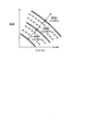
 図3は、本実施形態で用いる目標EGR率マップである。図3の目標EGR率マップは、同一負荷であればエンジン回転速度が高くなるほど目標EGR率が大きく、同一エンジン回転速度であれば負荷が大きくなるほど目標EGR率が大きくなっている。そして、図3の各EGR率を示す曲線は、等吸入空気量曲線と一致する。すなわち、図3の目標EGR率マップは、吸入空気量に基づいた目標EGR率が設定されており、吸入空気量が多いほど目標EGR率は大きく、吸入空気量が少ないほど目標EGR率は小さくなっている。 FIG. 3 is a target EGR rate map used in this embodiment. In the target EGR rate map of FIG. 3, the target EGR rate increases as the engine rotational speed increases at the same load, and the target EGR rate increases as the load increases at the same engine rotational speed. And the curve which shows each EGR rate of FIG. 3 corresponds with an equal intake air amount curve. That is, in the target EGR rate map of FIG. 3, the target EGR rate based on the intake air amount is set. The larger the intake air amount, the larger the target EGR rate, and the smaller the intake air amount, the smaller the target EGR rate. ing.
 なお、実際の制御においては、コントローラ100が、図2の目標EGR率マップで設定した目標EGR率を結果的に図3の目標EGR率マップに示す目標EGR率となるように、エアフローメータ3で検出した吸入空気量に基づいて補正してもよい。この場合、吸入空気量が少ないほど目標EGR率を小さくする補正量が大きくなる。また、吸入空気量が多いほど目標EGR率を大きくする補正量が大きくなる。 In actual control, the air flow meter 3 causes the controller 100 so that the target EGR rate set in the target EGR rate map of FIG. 2 becomes the target EGR rate shown in the target EGR rate map of FIG. You may correct | amend based on the detected intake air amount. In this case, the smaller the intake air amount, the larger the correction amount for reducing the target EGR rate. Further, the larger the intake air amount, the larger the correction amount for increasing the target EGR rate.
 上記のように目標EGR率を設定することで、図3の目標EGR率マップでは、図2の目標EGR率マップに比べて、低回転速度領域では目標EGR率が小さく、高回転速度領域では目標EGR率が大きくなっている。 By setting the target EGR rate as described above, the target EGR rate map of FIG. 3 has a lower target EGR rate in the low rotation speed region and a target in the high rotation speed region than the target EGR rate map of FIG. The EGR rate is increasing.
 低回転速度領域の目標EGR率が小さければ、排気側と吸気側との差圧が小さくても目標EGR率を達成し易くなるので、上述したような、低回転高負荷領域でのノッキングが発生し難くなる。 If the target EGR rate in the low rotation speed region is small, the target EGR rate can be easily achieved even if the differential pressure between the exhaust side and the intake side is small. Therefore, knocking in the low rotation and high load region as described above occurs. It becomes difficult to do.
 また、高回転速度領域では、吸入空気量が多いことにより差圧が生じ易いので、目標EGR率と実際のEGR率との乖離が生じ難く、ノッキングが発生し難い。したがって、図3の目標EGR率マップのように、より低い負荷から大きな目標EGR率を設定することで、EGRガス導入による燃費改善効果を高めることができる。 Also, in the high rotation speed region, a differential pressure is likely to be generated due to a large amount of intake air, so that the difference between the target EGR rate and the actual EGR rate is unlikely to occur, and knocking is unlikely to occur. Therefore, as shown in the target EGR rate map of FIG. 3, by setting a large target EGR rate from a lower load, the fuel efficiency improvement effect due to the introduction of EGR gas can be enhanced.
 ところで、目標EGR率マップは図3に示したものに限られるわけではなく、所定の吸入空気量範囲毎に目標EGR率がステップ的に変化するようにしてもよい。例えば、図4に示すように、運転領域を吸入空気量に応じて領域A、領域B、領域Cに分割し、各領域内は一律の目標EGR率で、吸入空気量が多い領域ほど大きな目標EGR率を設定したマップでもよい。 By the way, the target EGR rate map is not limited to that shown in FIG. 3, and the target EGR rate may be changed stepwise for each predetermined intake air amount range. For example, as shown in FIG. 4, the operation region is divided into region A, region B, and region C according to the intake air amount, and each region has a uniform target EGR rate, and a region with a larger intake air amount has a larger target. A map in which the EGR rate is set may be used.
 上記のように目標EGR率が所定の吸入空気量範囲毎にステップ的に変化する目標EGR率マップにすると、運転状態の変化量が小さければ目標EGR率は変動しなくなる。つまり、運転中の目標EGR率の変動が少なくなる。これにより、目標EGR率の変化に伴う点火時期補正やEGR弁11の開閉動作が煩雑になることを回避できる。 As described above, if the target EGR rate map is such that the target EGR rate changes stepwise for each predetermined intake air amount range, the target EGR rate will not fluctuate if the operating state change amount is small. That is, fluctuations in the target EGR rate during operation are reduced. Thereby, it is possible to avoid complication of the ignition timing correction and the opening / closing operation of the EGR valve 11 accompanying the change in the target EGR rate.
 以上、本発明の実施形態について説明したが、上記実施形態は本発明の適用例の一部を示したに過ぎず、本発明の技術的範囲を上記実施形態の具体的構成に限定する趣旨ではない。 The embodiment of the present invention has been described above. However, the above embodiment only shows a part of application examples of the present invention, and the technical scope of the present invention is limited to the specific configuration of the above embodiment. Absent.

Claims (3)

  1.  内燃機関の排気ガスの一部を、ターボ過給機のタービンよりも排気流れ下流側の排気通路から、ターボ過給機のコンプレッサよりも吸気流れ上流側かつエアフローメータより吸気流れ下流側の吸気通路に還流させる排気再循環通路と、
     前記吸気通路に還流させる排気ガスの量を調整する再循環制御弁と、
    を含む排気再循環装置を制御する排気再循環制御装置において、
     前記内燃機関の吸入空気量が少ないほど低い目標再循環率を設定する再循環率設定手段を備え、
     前記目標再循環率に応じて前記再循環制御弁の開度を制御する排気再循環制御装置。
    A part of the exhaust gas of the internal combustion engine is exhausted from the exhaust passage downstream of the turbocharger turbine, upstream of the compressor of the turbocharger, and downstream of the airflow meter. An exhaust gas recirculation passage that recirculates to
    A recirculation control valve for adjusting the amount of exhaust gas recirculated to the intake passage;
    In an exhaust gas recirculation control device for controlling an exhaust gas recirculation device including:
    Recirculation rate setting means for setting a lower target recirculation rate as the intake air amount of the internal combustion engine is smaller;
    An exhaust gas recirculation control device that controls the opening degree of the recirculation control valve in accordance with the target recirculation rate.
  2.  請求項1に記載の排気再循環制御装置において、
     前記再循環率設定手段は、前記目標再循環率を所定の吸入空気量範囲毎にステップ的に変化させる排気再循環制御装置。
    The exhaust gas recirculation control device according to claim 1,
    The exhaust gas recirculation control device, wherein the recirculation rate setting means changes the target recirculation rate stepwise for each predetermined intake air amount range.
  3.  内燃機関の排気ガスの一部を、ターボ過給機のコンプレッサよりも吸気流れ上流側かつエアフローメータより吸気流れ下流側の吸気通路に再循環させる排気再循環通路と、
     前記吸気通路に再循環させる排気ガスの量を調整する再循環制御弁と、
    を含む排気再循環装置を制御する排気再循環制御方法において、
     前記内燃機関の吸入空気量が少ないほど低い目標再循環率を設定し、
     前記目標再循環率に応じて前記再循環制御弁の開度を制御する排気再循環制御方法。
    An exhaust gas recirculation passage that recirculates a part of the exhaust gas of the internal combustion engine to an intake passage upstream of the compressor of the turbocharger and downstream of the airflow meter;
    A recirculation control valve for adjusting the amount of exhaust gas recirculated to the intake passage;
    In an exhaust gas recirculation control method for controlling an exhaust gas recirculation device including:
    A lower target recirculation rate is set as the intake air amount of the internal combustion engine is smaller,
    An exhaust gas recirculation control method for controlling an opening degree of the recirculation control valve in accordance with the target recirculation rate.
PCT/JP2014/061706 2014-04-25 2014-04-25 Exhaust gas recirculation control device and exhaust gas recirculation control method WO2015162779A1 (en)

Priority Applications (5)

Application Number Priority Date Filing Date Title
US15/305,518 US10100759B2 (en) 2014-04-25 2014-04-25 Exhaust gas recirculation control device and exhaust gas recirculation control method
JP2016514661A JP6210153B2 (en) 2014-04-25 2014-04-25 Exhaust gas recirculation control device and exhaust gas recirculation control method
EP14889919.8A EP3139026B1 (en) 2014-04-25 2014-04-25 Exhaust gas recirculation control device and exhaust gas recirculation control method
PCT/JP2014/061706 WO2015162779A1 (en) 2014-04-25 2014-04-25 Exhaust gas recirculation control device and exhaust gas recirculation control method
CN201480078163.XA CN106255819B (en) 2014-04-25 2014-04-25 EGR controller and control method for exhausting gas recycle

Applications Claiming Priority (1)

Application Number Priority Date Filing Date Title
PCT/JP2014/061706 WO2015162779A1 (en) 2014-04-25 2014-04-25 Exhaust gas recirculation control device and exhaust gas recirculation control method

Publications (1)

Publication Number Publication Date
WO2015162779A1 true WO2015162779A1 (en) 2015-10-29

Family

ID=54331966

Family Applications (1)

Application Number Title Priority Date Filing Date
PCT/JP2014/061706 WO2015162779A1 (en) 2014-04-25 2014-04-25 Exhaust gas recirculation control device and exhaust gas recirculation control method

Country Status (5)

Country Link
US (1) US10100759B2 (en)
EP (1) EP3139026B1 (en)
JP (1) JP6210153B2 (en)
CN (1) CN106255819B (en)
WO (1) WO2015162779A1 (en)

Cited By (3)

* Cited by examiner, † Cited by third party
Publication number Priority date Publication date Assignee Title
WO2017150077A1 (en) * 2016-03-04 2017-09-08 マツダ株式会社 Engine control device
CN107654314A (en) * 2016-07-26 2018-02-02 现代自动车株式会社 Engine system
US20180045144A1 (en) * 2016-08-10 2018-02-15 Hyundai Motor Company Method of removing impurities from egr by air blowing, egr system, and vehicle including the same

Families Citing this family (3)

* Cited by examiner, † Cited by third party
Publication number Priority date Publication date Assignee Title
WO2018026876A1 (en) * 2016-08-03 2018-02-08 Georgia-Pacific Gypsum Llc Gypsum panels, mats therefor, and methods
US10273965B2 (en) * 2016-08-08 2019-04-30 Borgwarner Inc. Method of extended thermodynamic turbine mapping via compressor inlet throttling
JP6565109B2 (en) * 2016-09-09 2019-08-28 日産自動車株式会社 Control method and control apparatus for internal combustion engine

Citations (5)

* Cited by examiner, † Cited by third party
Publication number Priority date Publication date Assignee Title
JPH09209798A (en) * 1996-01-31 1997-08-12 Fuji Heavy Ind Ltd Exhaust gas recirculating device for engine and its method
JPH1047120A (en) * 1997-03-28 1998-02-17 Toyota Motor Corp Detecting device of deposit
JPH10122057A (en) * 1996-10-11 1998-05-12 Nissan Motor Co Ltd Egr controller for engine
JP2002221102A (en) * 2001-01-22 2002-08-09 Toyota Motor Corp Compression ignition type internal combustion engine
JP2013011270A (en) * 2011-05-27 2013-01-17 Denso Corp Apparatus for estimating flow rate of egr gas flowing into cylinder of internal combustion engine

Family Cites Families (13)

* Cited by examiner, † Cited by third party
Publication number Priority date Publication date Assignee Title
JPS5364123A (en) * 1976-11-19 1978-06-08 Nissan Motor Co Ltd Exhaust reflux controller for internal combustion engines
US4398525A (en) * 1981-11-12 1983-08-16 Ford Motor Company Multi-stage exhaust gas recirculation system
US20080053419A1 (en) * 2006-08-31 2008-03-06 Caterpillar Inc. Low-idle exhaust gas recirculation system
JP2008138598A (en) * 2006-12-01 2008-06-19 Toyota Motor Corp Egr system for internal combustion engine
JP2008309053A (en) * 2007-06-14 2008-12-25 Toyota Motor Corp Control device for internal combustion engine
FR2940357B1 (en) 2008-12-18 2014-11-07 Valeo Sys Controle Moteur Sas THERMAL MOTOR WITH INTERNAL COMBUSTION, REGULATION SYSTEM, SIZING METHOD FOR MOTOR AND MOTOR VEHICLE WITH ENGINE
EP2474731B1 (en) * 2009-09-03 2020-08-19 Toyota Jidosha Kabushiki Kaisha Exhaust recirculation device for internal combustion engine
JP5912240B2 (en) * 2010-10-26 2016-04-27 いすゞ自動車株式会社 Exhaust gas recirculation device
JP4975158B2 (en) * 2010-11-08 2012-07-11 本田技研工業株式会社 Plant control equipment
WO2013021493A1 (en) * 2011-08-10 2013-02-14 トヨタ自動車 株式会社 Internal combustion engine control apparatus
KR101786651B1 (en) * 2011-08-12 2017-10-19 현대자동차주식회사 Control method for idle throttle valve of diesel vehicle
US20130080030A1 (en) * 2011-09-25 2013-03-28 John N. Chi System and method for determining engine cylinder peak operating parameters
US9239020B2 (en) * 2012-10-16 2016-01-19 Ford Global Technologies, Llc Condensate accumulation model for an engine heat exchanger

Patent Citations (5)

* Cited by examiner, † Cited by third party
Publication number Priority date Publication date Assignee Title
JPH09209798A (en) * 1996-01-31 1997-08-12 Fuji Heavy Ind Ltd Exhaust gas recirculating device for engine and its method
JPH10122057A (en) * 1996-10-11 1998-05-12 Nissan Motor Co Ltd Egr controller for engine
JPH1047120A (en) * 1997-03-28 1998-02-17 Toyota Motor Corp Detecting device of deposit
JP2002221102A (en) * 2001-01-22 2002-08-09 Toyota Motor Corp Compression ignition type internal combustion engine
JP2013011270A (en) * 2011-05-27 2013-01-17 Denso Corp Apparatus for estimating flow rate of egr gas flowing into cylinder of internal combustion engine

Non-Patent Citations (1)

* Cited by examiner, † Cited by third party
Title
See also references of EP3139026A4 *

Cited By (5)

* Cited by examiner, † Cited by third party
Publication number Priority date Publication date Assignee Title
WO2017150077A1 (en) * 2016-03-04 2017-09-08 マツダ株式会社 Engine control device
CN107654314A (en) * 2016-07-26 2018-02-02 现代自动车株式会社 Engine system
CN107654314B (en) * 2016-07-26 2020-08-18 现代自动车株式会社 Engine system
US20180045144A1 (en) * 2016-08-10 2018-02-15 Hyundai Motor Company Method of removing impurities from egr by air blowing, egr system, and vehicle including the same
CN107725222A (en) * 2016-08-10 2018-02-23 现代自动车株式会社 By blowing deimpurity method, egr system and vehicle comprising the egr system are removed from EGR

Also Published As

Publication number Publication date
EP3139026A4 (en) 2017-04-12
US20170045008A1 (en) 2017-02-16
JP6210153B2 (en) 2017-10-11
JPWO2015162779A1 (en) 2017-04-13
EP3139026A1 (en) 2017-03-08
US10100759B2 (en) 2018-10-16
EP3139026B1 (en) 2020-12-09
CN106255819A (en) 2016-12-21
CN106255819B (en) 2019-01-11

Similar Documents

Publication Publication Date Title
US9890718B2 (en) Control apparatus for internal combustion engine
JP6210153B2 (en) Exhaust gas recirculation control device and exhaust gas recirculation control method
US7395147B2 (en) Torque control of turbocharged engine
US9759165B2 (en) Internal combustion engine
US10119480B2 (en) Control apparatus for naturally aspirated gasoline engine
JP6156485B2 (en) Control device for internal combustion engine
JP5649343B2 (en) Intake throttle control method for internal combustion engine
US20200063673A1 (en) Engine system
EP3351773B1 (en) Control device for internal combustion engine and control method for internal combustion engine
JP6565109B2 (en) Control method and control apparatus for internal combustion engine
JP6458480B2 (en) Exhaust gas recirculation control device
JP2008190342A (en) Control device for internal combustion engine
JP6127906B2 (en) Control device for internal combustion engine
JP6005543B2 (en) Control device for supercharged engine
JP6536299B2 (en) Internal combustion engine control method and internal combustion engine control device
JP2015108315A (en) Control device of engine
JP6107876B2 (en) Control device for turbocharged engine
JP6458479B2 (en) Exhaust gas recirculation control device
JP6005534B2 (en) Control device for supercharged engine
WO2019198320A1 (en) Internal combustion engine control device and control method
JP6115571B2 (en) Diesel engine control device
JP6311363B2 (en) Control device for internal combustion engine
JP2012057488A (en) Control device of internal combustion engine
JP2013253532A (en) Egr device for supercharged engine
JP2010255546A (en) Internal combustion engine with supercharger

Legal Events

Date Code Title Description
121 Ep: the epo has been informed by wipo that ep was designated in this application

Ref document number: 14889919

Country of ref document: EP

Kind code of ref document: A1

ENP Entry into the national phase

Ref document number: 2016514661

Country of ref document: JP

Kind code of ref document: A

WWE Wipo information: entry into national phase

Ref document number: 15305518

Country of ref document: US

NENP Non-entry into the national phase

Ref country code: DE

REEP Request for entry into the european phase

Ref document number: 2014889919

Country of ref document: EP

WWE Wipo information: entry into national phase

Ref document number: 2014889919

Country of ref document: EP