WO2015162635A1 - Network management device and network management method - Google Patents
Network management device and network management method Download PDFInfo
- Publication number
- WO2015162635A1 WO2015162635A1 PCT/JP2014/002251 JP2014002251W WO2015162635A1 WO 2015162635 A1 WO2015162635 A1 WO 2015162635A1 JP 2014002251 W JP2014002251 W JP 2014002251W WO 2015162635 A1 WO2015162635 A1 WO 2015162635A1
- Authority
- WO
- WIPO (PCT)
- Prior art keywords
- path
- information
- resource
- communication
- normal
- Prior art date
Links
Images


Classifications
-
- H—ELECTRICITY
- H04—ELECTRIC COMMUNICATION TECHNIQUE
- H04L—TRANSMISSION OF DIGITAL INFORMATION, e.g. TELEGRAPHIC COMMUNICATION
- H04L45/00—Routing or path finding of packets in data switching networks
- H04L45/22—Alternate routing
-
- H—ELECTRICITY
- H04—ELECTRIC COMMUNICATION TECHNIQUE
- H04L—TRANSMISSION OF DIGITAL INFORMATION, e.g. TELEGRAPHIC COMMUNICATION
- H04L45/00—Routing or path finding of packets in data switching networks
- H04L45/02—Topology update or discovery
-
- H—ELECTRICITY
- H04—ELECTRIC COMMUNICATION TECHNIQUE
- H04L—TRANSMISSION OF DIGITAL INFORMATION, e.g. TELEGRAPHIC COMMUNICATION
- H04L45/00—Routing or path finding of packets in data switching networks
- H04L45/12—Shortest path evaluation
- H04L45/125—Shortest path evaluation based on throughput or bandwidth
Definitions
- the present invention relates to a network management apparatus and a network management method for managing communication resources in a communication system.
- a communication system composed of a plurality of communication devices (nodes) takes various redundant configurations to improve communication reliability in an end-to-end path.
- nodes a communication system that operates many paths in a limited communication resource of a small network cannot ensure redundancy for all paths, and can only have a redundant configuration for some paths. There is.
- a path that does not have a redundant configuration requires a temporary detour when a communication failure occurs or when a package is replaced.
- a detour is constructed when a detour is required, additional communication resources and operational costs are required each time.
- the communication resource refers to a resource used to logically divide a physical transmission path in multiplex communication. Examples of such communication resources include time slots in a TDM (Time Division Division Multiplex) network and wavelengths in a WDM (Wavelength Division Division Multiplex) network.
- TDM Time Division Division Multiplex
- WDM Widelength Division Division Multiplex
- Patent Document 1 An example of a technique related to such a problem is described in Patent Document 1.
- this related technology when setting a working path from a start point node to an end point node, a plurality of backup paths starting from each node on the working path are set.
- Patent Document 2 Another example of the technology related to the above-described problem is described in Patent Document 2.
- a certain node on the working path reserves a protection path by transferring a protection path reservation setting message to a detour that does not pass through the working path to a node downstream from the node. Then, the node on the working path that is the end of the protection path repeats the transfer of the protection path reservation setting message to the detour that does not pass through the working path to the downstream node in a chain manner.
- JP 2002-344491 A Japanese Patent Laid-Open No. 2005-210514
- Patent Document 1 and Patent Document 2 have the following problems.
- Patent Document 1 describes that a plurality of backup paths that are not used at the same time can share communication resources in a link between the same nodes. However, Patent Document 1 does not describe details of how to manage shared communication resources.
- Patent Document 2 describes that when communication resources are shared by a plurality of protection paths, a necessary communication resource amount in a common node on the plurality of protection paths is calculated. However, Patent Document 2 does not describe details of how shared communication resources are managed.
- the present invention has been made to solve the above-described problems, and an object of the present invention is to provide a technique for managing communication resources for detours with respect to paths in a network composed of a plurality of nodes so as to efficiently use the resources. To do.
- the network management apparatus of the present invention assigns each of two sets of a plurality of communication apparatuses (nodes) capable of communicating with each other to a normal or backup communication path (path) between the two nodes and the path.
- Path information storage means for storing path information including information representing each of the one or more communication resources, resource information storage means for storing allocation status information indicating an allocation status for the path for each communication resource;
- an allocation status determination unit that determines the allocation status of one or more communication resources allocated to the path indicated by the path information with reference to the resource information storage unit;
- the input path information indicates a normal path before registration, one or more communication resources allocated to the normal path before registration
- the allocation status determination means determines that no path is allocated to any other registered path, the path setting based on the input path information is notified to each node on the normal path.
- Normal path registration means for registering the input path information in the path information storage means and updating the allocation status information for one or more communication resources assigned to the normal path; and the input path
- the allocation status determination is made if any one or more communication resources allocated to the backup path before registration are not allocated to the other registered normal paths.
- the communication apparatus of the present invention is notified by the above-described network management apparatus to perform route setting based on the path information, the path between itself and another communication apparatus adjacent to the own apparatus on the path Path setting means for setting a route to perform communication using the communication resource allocated to the network, and a multiplex communication means for performing multiplex communication with the other communication device based on the setting by the path setting means; .
- the communication system of the present invention includes the above-described network management device and the above-described communication device.
- the network management method of the present invention provides a normal or backup communication path (path) between the two nodes for each of two sets of a plurality of communication devices (nodes) capable of communicating with each other, and the path.
- Path information storage means for storing path information including information representing each of one or more communication resources allocated to the resource, and resource information storage means for storing allocation status information indicating an allocation status for the path for each communication resource
- the allocation status of one or more communication resources allocated to the path indicated by the path information is determined with reference to the resource information storage unit
- the input path information indicates a normal path before registration
- one or more communication resources allocated to the normal path before registration are When it is determined that no deviation is assigned to another registered path, the path setting based on the input path information is notified to each node on the normal path, and the input path information is When registering in the path information storage means and updating the allocation status information for one or more communication resources allocated to the normal path, and the input path information indicates a spare path before registration, the registration When it is
- the storage medium of the program of the present invention includes, for each of two sets of a plurality of communication devices (nodes) capable of communicating with each other, a normal or backup communication path (path) between the two nodes, and Path information storage means for storing path information including information representing each of one or more communication resources allocated to the path, and resource information storage for storing allocation status information indicating an allocation status for the path for each communication resource
- path information including information representing each of one or more communication resources allocated to the path
- resource information storage for storing allocation status information indicating an allocation status for the path for each communication resource
- the registered path information indicates a backup path before registration, one or more communication resources allocated to the backup path before registration are not allocated to the other registered normal paths.
- One of the input path information registered in the path information storage means and allocated to the spare path when determined in the allocation status determination step Storing a computer program for executing a backup path registration updating the allocation status information about the communication resources of the upper, to the computer device.
- the present invention provides a technique for managing communication resources for detours with respect to a path in a network composed of a plurality of nodes so as to be efficiently used.
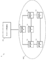
- FIG. 1 shows a configuration of a communication system 1 as a first embodiment of the present invention.
- the communication system 1 includes a communication device 10 and a network management device 20.
- the communication device 10 is also referred to as a node 10.
- the network management device 20 is communicably connected to a network 100 composed of a plurality of nodes 10. Each node 10 is communicably connected to one or more other nodes 10 in the network 100.
- FIG. 1 shows four communication devices 10 and one network management device 20, the number of devices in the communication system of the present invention is not limited.
- the node 10 is a communication device that performs multiplex communication, and has a cross-connect function.
- the cross-connect function is a function for arbitrarily setting a route between a plurality of multiplexed input / output signals. That is, based on which communication resource is used to input each signal that has been multiplexed and input from which other node 10, the node 10 uses which communication resource to transmit the signal. Whether to output to the node 10 is set, and signals are multiplexed and output for each route according to the setting.
- the communication resource refers to a resource used to logically divide a physical transmission path in multiplex communication.
- communication resources include time slots in TDM (Time Division Division Multiplex), wavelengths in a WDM (Wavelength Division Division Multiplex) network, and the like.
- Each node 10 is preinstalled with one or more communication resources that can be used for communication with other nodes.
- the node 10 includes a path setting unit 11 and a multiplex communication unit 12.
- the network management device 20 includes a path information storage unit 21, a resource information storage unit 22, an allocation status determination unit 23, a normal path registration unit 24, and a backup path registration unit 25.
- FIGS. 1 An example of the hardware configuration of each device constituting the communication system 1 is shown in FIGS.
- FIG. 3 is a diagram illustrating an example of a hardware configuration of the communication device (node) 10.
- the node 10 includes one or more interfaces 1001, a switch 1002, and a control unit 1003 including a processor and a memory.
- the interface 1001 is connected to another node 10, the network management device 20, or other external device via a link.
- the interface 1001 separates multiplexed signals input via the link and outputs the separated signals to the switch 1002.
- the interface 1001 multiplexes signals input from the switch 1002 and outputs the multiplexed signals via a link.
- the switch 1002 sets the path of the signal input from each interface 1001 and outputs it to the appropriate interface 1001.
- the memory of the control unit 1003 stores a computer program and various data for causing the apparatus to function as the node 10 of the present embodiment.
- the control unit 1003 controls the path setting of the switch 1002 by reading and executing the computer program and various data stored in the memory.
- the path setting unit 11 described above is configured by the control unit 1003.
- the multiplex communication unit 12 includes an interface 1001 and a switch 1002. Note that the hardware configuration configuring the node 10 and each functional block thereof is not limited to the above-described configuration.
- FIG. 4 is a diagram illustrating an example of a hardware configuration of the network management device 20.
- the network management apparatus 20 includes a processor 2001, a memory 2002, a storage device 2003 such as a hard disk, a network interface 2004, an input device 2005, and an output device 2006.
- the storage device 2003 stores a computer program and various data for causing the device to function as the network management device 20 of the present embodiment.
- the processor 2001 manages communication in the communication system 1 by reading the computer program and various data stored in the storage device 2003 into the memory 2002 and executing them.
- the network interface 2004 communicates with the node 10 via the network 100.
- the above-described path information storage unit 21 and resource information storage unit 22 are configured by the storage device 2003.
- the allocation status determination unit 23 includes an input device 2005 and a processor 2001.
- the normal path registration unit 24 includes a network interface 2004 and a processor 2001.
- the backup path registration unit 25 is configured by the processor 2001.
- the processor 2001 constituting each unit reads the computer program and various data stored in the storage device 2003 into the memory 2002 and executes them. Note that the hardware configuration of the network management device 20 and each functional block thereof is not limited to the above-described configuration.
- the network management device 20 may not be connected to each node 10 so as to be directly communicable.
- the network management device 20 may communicate with each node 10 by being connected to any one of the nodes 10.
- the network management device 20 may be connected to the network 100 configured by the node 10 via another network.
- the path setting unit 11 sets a working path in the own apparatus based on information notified from the network management apparatus 20. Specifically, the path setting unit 11 receives information representing the path of the working path and information representing the communication resource to be used from the network management device 20. Then, the path setting unit 11 notifies the adjacent node 10 of the signal input using the notified communication resource from one node 10 adjacent to the own device on the notified route. Set the path to output using the specified communication resource.
- the multiplex communication unit 12 performs multiplex communication with other nodes 10 based on the setting by the path setting unit 11.
- the path information storage unit 21 stores path information related to a communication path (path) between any two nodes 10 (endpoint nodes). Specifically, the path information storage unit 21 stores path information including information representing a normal or backup communication path (path) between two nodes and one or more communication resources allocated to the path. is doing.
- a backup path (backup path) is a communication path different from a normal path (normal path) between end point nodes.
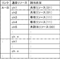
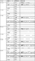
- each row represents path information.
- the path information includes a path ID, end point information, normal path route information, normal path resource information, protection path route information, and protection path resource information.
- the path ID is information for identifying the path.
- the path ID is represented by #N.
- the path with path ID #N is also referred to as path #N.
- N is a natural number.
- the end point information represents two end point nodes.
- the end point information “A, C” of the path # 2 indicates that the identifiers of the node 10 at the end point are “A” and “C”, respectively.
- the node 10 having the identifier “X” is also referred to as a node 10X.
- the normal path route information “AEFC” of path # 2 represents a normal communication route between the node 10A and the node 10C which are end point nodes.
- the normal path route information is represented as a list in which the identification information of the nodes 10 on the normal path are arranged in order.
- the normal path resource information “ch7” of path # 2 indicates that the communication resource of channel 7 (ch7) is assigned to the normal path. Specifically, this normal path resource information is obtained by comparing the normal path “AEFC” with the ch7 in the link “AE”, the ch7 in “EF”, and the “FC”. This indicates that three communication resources of ch7 are allocated.
- the link “XY” refers to a link connecting the node 10X and the node 10Y.
- the backup path route information “ABC” of the path # 2 represents a communication route different from the normal path between the node 10A and the node 10C as the end point nodes.
- the backup path route information is also expressed as a list in which the identification information of the nodes 10 on the route are arranged in order, like the normal path route information.
- the protection path resource information “ch2” of path # 2 indicates that the communication resource of channel 2 (ch2) is allocated to the protection path. Specifically, in this protection path resource information, two communication resources of ch2 in the link “AB” and ch2 in “BC” are allocated to the protection path “ABC”. Represents that
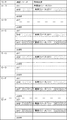
- the resource information storage unit 22 stores allocation status information regarding each communication resource. For example, it is assumed that there are N links connecting the nodes 10 in the network 100. Further, it is assumed that n communication resources are mounted on each node 10. n is a natural number. In this case, the resource information storage unit 22 stores allocation status information for each of n communication resources in each of N links.
- the allocation status information represents an allocation status for each communication resource path.
- the allocation status information may be information indicating any of a shared resource, a dedicated resource, and an unallocated resource.
- the shared resource is a communication resource that can be shared and allocated to a plurality of backup paths.
- a dedicated resource is a communication resource allocated exclusively for one normal path.
- An unassigned resource is a communication resource that has not been assigned to any path.
- each of the first to nth rows shows allocation status information regarding each of n communication resources (ch1 to chn) that can be used in the link “AB” between the node 10A and the node 10B.
- the communication resources of ch1 and ch2 in the link “AB” are shared resources.
- the communication resources of ch3 and ch4 of link “AB” are exclusive resources.
- the channel 5 communication resource of the link “AB” is an unallocated resource.
- the resource information storage unit 22 may store allocation status information represented by 2 bits for each communication resource of each link.
- the shared resource may be represented by “01”, the dedicated resource may be represented by “11”, and the unallocated resource may be represented by “00”.
- the allocation status information may be in any format as long as the information indicates the allocation status for each communication resource path.
- the allocation status determination unit 23 determines the allocation status of one or more communication resources allocated to the path indicated by the path information with reference to the resource information storage unit 22. .
- the allocation status determination unit 23 may acquire path information via the input device 2005. Alternatively, the allocation status determination unit 23 may acquire path information from an operator terminal (not shown) connected to be communicable.
- the normal path registration unit 24 is configured to function when the input path information indicates a normal path before registration.
- the path information indicating the normal path before registration includes route information as a normal path and information indicating a communication resource scheduled to be allocated to the normal path.
- the normal path registration unit 24 determines that the allocation status for one or more communication resources scheduled to be allocated to the normal path before registration is not allocated to any other path by the allocation status determination unit 23. The following processing is performed. For example, the normal path registration unit 24 may perform the following process when one or more communication resources scheduled to be allocated to the normal path before registration are all unallocated resources.
- the normal path registration unit 24 notifies each node 10 on the input normal path to perform route setting based on the path information. For example, the normal path registration unit 24 sends information input to each corresponding node 10 from the adjacent node 10 on the normal path using the communication resource to the other node 10. What is necessary is just to transmit the message which requests
- the normal path registration unit 24 registers the path information representing the input normal path in the path information storage unit 21.
- the normal path registration unit 24 registers the path information to which the new path ID is assigned, and the information and communication indicating the path of the input normal path in the normal path path information and the normal path resource information of the path information. What is necessary is just to set the information showing a resource.
- the normal path registration unit 24 updates the resource information storage unit 22 when the normal path setting is successful. For example, the normal path registration unit 24 may update the allocation status information for each communication resource allocated to the normal path to “exclusive resource”.
- the normal path registration unit 24 When the normal path registration unit 24 assigns at least one of one or more communication resources scheduled to be assigned to the input normal path to another path (for example, a dedicated resource or a shared resource). Does not perform normal path setting and normal path registration. In this case, for example, the normal path registration unit 24 may output, to the output device 2006, a message indicating that the communication resource is already assigned to another path and cannot be assigned as a dedicated resource.
- the backup path registration unit 25 is configured to function when the input path information indicates a backup path before registration.
- the path information indicating the backup path before registration includes route information as a backup path and information indicating a communication resource scheduled to be assigned to the backup path.
- the path information indicating the backup path before registration may include information on a path ID and an end point node as information that can specify which normal path is the backup path.
- the backup path registration unit 25 indicates that the allocation status of one or more communication resources scheduled to be allocated to the backup path before registration indicates that none of the allocation status is allocated to another normal path. If the determination is made at step 23, the following processing is performed.
- the protection path registration unit 25 may perform the following process when one or more communication resources scheduled to be assigned to the protection path before registration are shared resources or unallocated resources.
- the backup path registration unit 25 registers path information representing the backup path in the path information storage unit 21. Specifically, the backup path registration unit 25 searches the path information storage unit 21 for path information including a normal path corresponding to the input backup path. Then, the protection path registration unit 25 may set the information indicating the route of the input protection path and the information indicating the communication resource in the protection path route information and the protection path resource information of the searched path information.
- the backup path registration unit 25 updates the resource information storage unit 22.
- the protection path registration unit 25 may update the allocation status information to “shared resource” for each communication resource allocated to the protection path.
- the protection path registration unit 25 does not notify each node 10 on the route of the route setting when the protection path is registered.
- the backup path registration unit 25 also assigns at least one of one or more communication resources scheduled to be assigned to the input backup path to another normal path (for example, a dedicated resource). Does not register a backup path.
- the backup path registration unit 25 may output to the output device 2006 a message indicating that the communication resource is already allocated by another normal path and cannot be assigned as a shared resource.
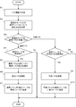
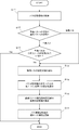
- FIG. 7 is a flowchart illustrating the path registration operation of the communication system according to the first embodiment.
- the allocation status determination unit 23 acquires path information before registration input from the outside (step S1).
- the pre-registration path information input here includes at least information representing a normal path or backup path and information representing one or more communication resources to be allocated to the path. Further, as described above, when the input path information represents a backup path before registration, the input path information includes information such as a path ID and an end node that can identify the corresponding normal path. May be.
- the allocation status determination unit 23 acquires allocation status information regarding one or more communication resources acquired in step S1 from the resource information storage unit 22 (step S2).
- the allocation status determination unit 23 determines whether the path information acquired in step S1 represents a normal path before registration or a backup path before registration (step S3).
- step S3 normal path
- step S4 the allocation status determination unit 23 does not allocate the allocation status of each communication resource acquired in step S2 to any other path. Is determined (step S4).
- the allocation status determination unit 23 Whether or not each communication resource is an unallocated resource that is not allocated to another path may be determined based on whether or not the first bit is 0.
- the normal path registration unit 24 determines that the input normal path cannot be registered. End the operation. In this case, the normal path registration unit 24 may output a message indicating that this communication resource cannot be assigned to the normal path.
- step S4 when it is determined in step S4 that each communication resource is not assigned to any other path (step S4: Yes), the normal path registration unit 24 adds each node 10 on the input normal path. The route setting based on this path information is notified (step S5).
- the normal path registration unit 24 registers path information representing this normal path in the path information storage unit 21 (step S6).
- the normal path registration unit 24 registers path information with a new path ID, sets information indicating the path of the input normal path in the normal path path information, and sets the normal path resource information in the normal path resource information.
- Information representing one or more input communication resources is set.
- the normal path registration unit 24 updates the allocation status information stored in the resource information storage unit 22 for one or more communication resources allocated to the normal path registered in step S6 (step S7).
- the normal path registration unit 24 may update the allocation status information of each corresponding communication resource to “exclusive resource”.
- the normal path registration unit 24 ends the operation without executing steps S6 to S7 if the normal path setting is not successful in step S5. In this case, the normal path registration unit 24 may output a message indicating that the normal path route setting has failed.
- step S3 when it is determined in step S3 that the path information acquired in step S1 indicates a backup path before registration (step S3: backup path), the allocation status determination unit 23 performs each communication acquired in step S2. It is determined whether the resource allocation status is assigned to any other normal path (step S8).
- the allocation status determination unit 23 is allocated to another normal path depending on whether the second bit from the upper level is 0 or not. It may be determined whether or not there are no shared resources or unallocated resources.
- step S8 when it is determined that at least one of the communication resources is assigned to another normal path (for example, a dedicated resource) (step S8: No), the backup path registration unit 25 is input. If the backup path cannot be registered, the operation is terminated. At this time, the protection path registration unit 25 may output a message indicating that this communication resource cannot be assigned to the protection path.
- step S8 determines whether none of the communication resources is assigned to another normal path.
- the backup path registration unit 25 stores the backup information in the path information storage unit 21.
- Path information representing the path is registered (step S9).
- the backup path registration unit 25 searches the path information storage unit 21 for path information to which the path ID included in the path information input in step S1 is assigned.
- the protection path registration unit 25 sets information indicating the route of the input protection path in the protection path route information of the searched path information, and one or more input communication resources are input to the protection path resource information. Set the information indicating.
- the protection path registration unit 25 updates the allocation status information stored in the resource information storage unit 22 for each communication resource allocated to the protection path registered in step S9 (step S10). For example, the protection path registration unit 25 may update the allocation status information for each corresponding communication resource to “shared resource”.
- the communication system 1 finishes the path registration operation.
- the communication system 1 includes six nodes 10 with identifiers “A” to “F” and a network management device 20.
- a solid line connecting the nodes 10A to 10F represents a link connecting the nodes 10. That is, in this example, there are seven links between each node 10.
- each node 10 has 88 channels of communication resources from ch1 to ch88, and can register 88 paths.
- the resource information storage unit 22 stores the allocation status information of 88 communication resources that can be used in each link in communication performed via the seven links.
- an example of information stored in the resource information storage unit 22 is shown in FIG. In FIG. 9, since no single path has been registered yet, all communication resources are unallocated resources.
- the allocation status determination unit 23 acquires information indicating the route “EF” as the normal path before registration and information indicating the communication resource “ch2” to be allocated to the normal path. (Step S1).
- the allocation status determination unit 23 acquires allocation status information of the communication resource “ch2” on the link “EF” on the path “EF” from the resource information storage unit 22 (step S2).
- the allocation status determination unit 23 acquires information representing “unallocated resources” from the information shown in FIG. 9 stored in the resource information storage unit 22.
- step S3 Since the input path information represents a normal path before registration (“normal path” in step S3) and the communication resource scheduled to be allocated to the normal path is “unallocated resource” (Yes in step S4), the network The operation of the management device 20 proceeds to step S5.
- the normal path registration unit 24 notifies the route setting of the normal path “EF” using ch2 to the nodes 10E and 10F on the input normal path (step S5).
- the node 10E and the node 10F perform route setting of the normal path “EF” using ch2.
- the normal path registration unit 24 registers the path information with the new path ID “# 1” in the path information storage unit 21, sets “EF” in the normal path route information, “Ch2” is set in the normal path resource information (step S6).
- the normal path registration unit 24 assigns the exclusive status information stored in the resource information storage unit 22 to the communication resource “ch2” allocated to the link “EF” on the normal path “EF”. Update to “resource” (step S7).
- information as shown in FIG. 11 is stored in the resource information storage unit 22.
- information shown in bold represents information updated in the resource information storage unit 22.
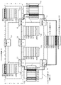
- FIG. 12 schematically shows a state where the normal path “EF” of the path # 1 is set as the working path in this way.
- rectangles to which reference numerals ch1 to ch88 are attached represent 88-channel communication resources that can be used in each link.
- a rectangle filled with a diagonal line pattern represents “exclusive resource”.
- a rectangle surrounded by a double line represents a communication resource used by the corresponding node 10 in the corresponding link. That is, in FIG. 12, the communication resource of “ch2” in the link “EF” is a dedicated resource and is used by the nodes 10E and 10F.
- the allocation status determination unit 23 includes information indicating the route “EABCCF” as the backup path before registration of the path # 1, and the communication resource scheduled to be allocated to this backup path.
- Information representing “ch2” is acquired (step S1).
- the allocation status determining unit 23 acquires allocation status information of the communication resource “ch2” in each link on the path “EABC” from the resource information storage unit 22 (step S2). ).
- the allocation status determination unit 23 uses the links “EA”, “AB”, “BC”, “C” from the information shown in FIG. 11 stored in the resource information storage unit 22. It is assumed that information indicating “unallocated resource” is acquired for each communication resource “ch2” in ⁇ F ”.
- the input path information represents a backup path before registration (“backup path” in step S3), and each communication resource scheduled to be assigned to the backup path is an “unassigned resource” (in step S8). Yes), the operation of the network management device 20 proceeds to step S9.
- the protection path registration unit 25 sets “EABC” as the protection path route information of the path information of the path # 1 in the path information storage unit 21, and sets “E-ABC” as the protection path resource information.
- ch2 is set (step S9).
- the protection path registration unit 25 assigns the allocation status information stored in the resource information storage unit 22 for the communication resource “ch2” allocated to each link on the protection path “EABCCF”. Update to “shared resource” (step S10).
- FIG. 15 schematically shows a state in which the backup path “EABCCF” using ch2 is secured in this way for path # 1.
- a rectangle filled with a dot pattern represents a “shared resource”. That is, in FIG. 15, the communication resources of “ch2” in the links “EA”, “AB”, “BC”, and “CF” are shared resources. Note that the communication resource of “ch2” in each of these links is managed as a shared resource in the resource information storage unit 22 of the network management device 20, but is not used by the corresponding node 10.
- the allocation status determination unit 23 obtains information representing the route “AEFC” as the normal path before registration and information representing the communication resource “ch7” to be allocated to this normal path. (Step S1).
- the allocation status determination unit 23 acquires the allocation status information of the communication resource “ch7” in each link on the path “AEFC” from the resource information storage unit 22 (step S2).
- the allocation status determination unit 23 uses the information shown in FIG. 14 stored in the resource information storage unit 22 in the links “AE”, “EF”, and “FC”. It is assumed that information indicating “unallocated resource” is acquired for each communication resource “ch7”.
- the input path information represents the normal path before registration (“normal path” in step S3), and any of the communication resources scheduled to be allocated to the normal path is “unallocated resource” (Yes in step S4). )
- the operation of the network management device 20 proceeds to step S5.
- the normal path registration unit 24 sets the path of the normal path “AEFC” using ch7 for the nodes 10A, 10E, 10F, and 10C on the input normal path. Notification is made (step S5). As a result, the node 10A, the node 10E, the node 10F, and the node 10C perform communication route setting using the ch7 with the adjacent node 10.
- the normal path registration unit 24 registers the path information assigned with the new path ID “# 2” in the path information storage unit 21, and “AEFC” is added to the normal path route information. And “ch7” is set in the normal path resource information (step S6).
- the path information storage unit 21 stores information as shown in FIG.
- the normal path registration unit 24 assigns the allocation status information stored in the resource information storage unit 22 to the “proprietary resource” for the normal path resource “ch7” in each link on the normal path “AEFC”. (Step S7).
- FIG. 18 schematically shows a state where the normal path of path # 2 is set as the working path in addition to the normal path (working path) and backup path of path # 1 in this way.
- the communication resources of “ch7” in the links “AE”, “EF”, and “FC” are exclusive resources and are used by the corresponding node 10.
- the allocation status determination unit 23 includes information indicating the route “ABC” as the backup path before registration of the path # 2, and information indicating the communication resource “ch2” scheduled to be allocated to the backup path. Is acquired (step S1).
- the allocation status determination unit 23 acquires the allocation status information of the communication resource “ch2” in each link on the path “ABC” from the resource information storage unit 22 (step S2).
- the allocation status determination unit 23 uses the information shown in FIG. 17 stored in the resource information storage unit 22 for the communication resource “ch2” in the links “AB” and “BC”. It is assumed that information indicating “shared resource” has been acquired.
- the input path information represents a backup path before registration (“backup path” in step S3), and each communication resource scheduled to be allocated to the backup path is a “shared resource” (Yes in step S8). )
- the operation of the network management device 20 proceeds to step S9.
- the protection path registration unit 25 sets “ABC” in the protection path route information of the path information of the path # 2 in the path information storage unit 21, and sets “ch2” in the protection path resource information. (Step S9).
- the protection path registration unit 25 uses the allocation status information stored in the resource information storage unit 22 for the communication resource “ch2” allocated to each link on the protection path “ABC” to “shared resource”. (Step S10).
- the allocation status information of the communication resource “ch2” in the links “AB” and “BC” is already “shared resource”. In this case, the protection path registration unit 25 does not have to update the allocation status information.
- the information stored in the resource information storage unit 22 at this time is the same as that shown in FIG.
- FIG. 20 schematically shows a state where the backup path “ABC” using ch2 is secured in this way for path # 2. As shown in FIG. 20, ch2 is shared and assigned to each protection path for path # 1 and path # 2 in link “AB” and link “BC”.
- the communication system according to the first exemplary embodiment of the present invention can be managed so as to efficiently use communication resources for detouring a path in a network including a plurality of nodes.
- the resource information storage unit of the network management device stores allocation status information indicating the allocation status for the path for each communication resource in the network, and the allocation status determination unit is a communication scheduled to be allocated to the input path. This is because the resource allocation status is determined. Specifically, when the allocation status determination unit determines that none of each communication resource scheduled to be allocated to each link on the normal path before registration is allocated to another registered path, This is because the normal path registration unit notifies each node on the input normal path of the route setting based on the input path information. This is because the normal path registration unit registers the input path information indicating the normal path in the path information storage unit and updates the allocation status information for each communication resource allocated to the normal path.
- the allocation status determination unit determines that none of the communication resources scheduled to be allocated to each link on the backup path before registration is assigned to another registered normal path, the backup path This is because the registration unit registers the input path information representing the protection path in the path information storage unit and updates the allocation status information for each communication resource allocated to the protection path.
- the network management device has communication resources that are exclusively allocated to one normal path and communication resources that can be shared and allocated to a plurality of backup paths. And can be managed separately.
- the communication resources allocated to the normal path are exclusively used by the normal path, and are not allocated to other normal paths or backup paths.
- the communication resources allocated to the protection path can be shared and allocated to other protection paths.
- the administrator using the network management apparatus according to the first embodiment of the present invention plans in advance which communication resources should be reserved in advance as a shareable communication resource in the network design stage. be able to. Therefore, this embodiment can also reduce operation costs.
- FIG. 21 shows a configuration of a communication system 2 as a second embodiment of the present invention.
- the communication system 2 is different from the communication system 1 according to the first embodiment of the present invention in that a network management device 30 is provided instead of the network management device 20.
- FIG. 22 shows functional blocks of the network management device 30.
- the network management device 30 is different from the network management device 20 according to the first embodiment of the present invention in the path information storage unit 31 and the resource information storage unit 22 instead of the path information storage unit 21.
- a resource information storage unit 32, a normal path registration unit 34 instead of the normal path registration unit 24, and a path switching unit 36 are further provided.
- the network management device 30 can be configured by hardware components similar to the network management device 20 described with reference to FIG. 4 in the first embodiment of the present invention.
- the path switching unit 36 includes a network interface 2004, an input device 2005, and a processor 2001 that reads a computer program and various data stored in the storage device 2003 into the memory 2002 and executes them.
- the hardware configuration that configures the network management device 30 and each functional block thereof is not limited to the above-described configuration.
- the path information storage unit 31 indicates that the working path set as the communication path between the endpoint nodes is the normal path and the backup path.
- the working path information indicating which one is stored is further stored.
- FIG. 23 an example of information stored in the path information storage unit 31 is shown in FIG. In FIG. 23, the normal path is the working path for both path # 1 and path # 2.
- the resource information storage unit 32 stores the usage status information by the node 10 in addition to the allocation status information similar to that of the first embodiment of the present invention for each communication resource that can be used between the adjacent nodes 10 in the network 100.
- the usage status information indicates whether or not the communication resource is used by the node 10 in communication via the link.
- FIG. 24 an example of information stored in the resource information storage unit 32 is shown in FIG.
- the shared resource “ch2” is in the “OFF (not used)” state, and is a dedicated resource “ch7”. Is the “ON (used)” state.
- the normal path registration unit 34 is configured in the same manner as the normal path registration unit 24 in the first embodiment of the present invention. In addition, when registering a normal path in the path information storage unit 31, the normal path registration unit 34 “Normal path” is set in the working path information. In addition, the normal path registration unit 34 updates the use status information of the communication resource indicated by the registered normal path resource information to the “ON (used)” state.
- the path switching unit 36 determines whether switching to the path indicated by the path switching information is possible.
- the path switching information is information indicating a switching instruction as to which one of the normal path and the protection path is the active path.
- the path switching information includes information for specifying a path (such as a path ID and end point node information) and information indicating a path after switching (a normal path or a backup path). Specifically, the path switching unit 36 determines that the path can be switched if switching to the normal path. This is because the communication resources allocated to the normal path are managed as exclusive resources and are not used by other working paths.
- the path switching unit 36 determines whether or not the communication resource allocated to the protection path is used in communication using another working path. At this time, the path switching unit 36 may determine whether or not switching to the protection path is possible by referring to the usage status information for each communication resource stored in the resource information storage unit 32. For example, the path switching unit 36 determines that switching to the backup path is possible if none of the communication resources allocated to the backup path is in use (“OFF”).
- the path switching unit 36 cancels the setting of the working path and then executes the path switching.
- the path switching unit 36 specifies each node 10 on the path set as the working path before switching by referring to the working path information in the path information storage unit 31. Then, the path switching unit 36 notifies each node 10 on the working path before switching to cancel the setting of the working path and release the used communication resource.
- the path switching unit 36 sets the working path for each node 10 on the path indicated by the path switching information using the communication resource assigned to the path. Notice.
- the path switching unit 36 updates the working path information in the path information storage unit 31 after successfully switching the path. Further, the path switching unit 36 updates the usage status information stored in the resource information storage unit 32 for the communication resource whose usage status has changed due to the path switching. Specifically, the path switching unit 36 updates the usage status information regarding the communication resources released by releasing the working path before switching to information indicating the “OFF (not used)” state. In addition, the path switching unit 36 updates the usage status information regarding the communication resources used by the switched working path to information indicating the “ON (used)” state.
- the path registration operation of the communication system 2 is substantially the same as the path registration operation of the communication system 1 according to the first embodiment of the present invention described with reference to FIG. However, in this embodiment, the details of the operations in step S6 and step S7 in FIG. 7 are different.
- the normal path registration unit 34 registers the normal path in the path information storage unit 31 in step S6, the normal path registration unit 34 further sets “normal path” in the working path information in the registered path information.
- the normal path registration unit 34 updates the allocation status information of the corresponding communication resource to “exclusive resource” in the resource information storage unit 32, and further changes the usage status information to “ON ( It is updated to information indicating the “used” state.
- the path switching unit 36 acquires path switching information (step S11).
- the path switching information includes information such as a path ID for specifying a path and information indicating a path after switching (normal path or backup path).
- the path switching unit 36 determines whether the path switching information indicates switching to the normal path or switching to the backup path (step S12).
- the path switching unit 36 determines that switching is possible, and proceeds to step S14.
- the path switching unit 36 determines whether the shared resource allocated to the protection path indicated by the path switching information is used (step S13). . Specifically, in step S13, the path switching unit 36 determines whether or not all of the one or more communication resources allocated to the protection path indicated by the path switching information are in the “OFF (not used)” state. to decide. At this time, the path switching unit 36 refers to the path information storage unit 31 to identify each communication resource assigned to the backup path indicated by the path switching information. Then, the path switching unit 36 acquires the usage status information of each communication resource allocated to the backup path from the resource information storage unit 32. Then, the path switching unit 36 may determine whether or not all of the acquired usage status information represents an “OFF (not used)” state.
- the path switching unit 36 It is determined that the protection path indicated by the switching information can be switched, and the process proceeds to step S14.
- step S14 the path switching unit 36 specifies each node 10 on the working path by referring to the working path information in the path information storage unit 31. Specifically, the path switching unit 36 identifies each node 10 on the normal path if the working path information indicates a normal path, and each node on the protection path if the working path information indicates a protection path. 10 may be specified. Then, the path switching unit 36 notifies each node 10 on the working path to cancel the setting of the working path and release the used communication resources (step S14).
- the path switching unit 36 notifies each node 10 on the path indicated by the path switching information to set the working path using each communication resource allocated to the path (step S15).
- the path switching unit 36 updates the resource information storage unit 32 (step S16). Specifically, the path switching unit 36 updates the usage status information of the communication resource released in step S14 to information indicating the “OFF (not used)” state. Further, the path switching unit 36 updates the usage status information of the communication resources on the path set in step S15 to information indicating the “ON (used)” state.
- the path switching unit 36 updates the working path information of the corresponding path information (step S17).
- the communication system 2 ends the path switching operation.
- the configuration of the communication system 2 in this specific example is the same as the configuration of the specific example of the communication system 1 described with reference to FIG. Further, it is assumed that the information shown in FIG. 23 is stored in the path information storage unit 31, and the information shown in FIG. 24 is stored in the resource information storage unit 32.
- the path switching unit 36 acquires information instructing “switch to a backup path in path # 1” as path switching information (step S11).
- the path switching section 36 Since the path switching information indicates switching to the protection path (“protection path” in step S12), the path switching section 36 is assigned to each link on the corresponding protection path “EABCCF”.
- the usage status information of the communication resource “ch2” is acquired from the information shown in FIG. 24 stored in the resource information storage unit 32.
- the path switching unit 36 determines that it can be switched to the backup path indicated by the path switching information, and the step Proceed to S14.
- the path switching unit 36 refers to the path information storage unit 31 to identify the node 10E and the node 10F on the normal path that is the working path of the path # 1. Then, the path switching unit 36 notifies the identified nodes 10E and 10F to cancel the setting of the working path and release the used communication resource “ch2” (step S14).
- the path switching unit 36 uses the communication resources “ch2” allocated to the protection path for each of the nodes 10E, 10A, 10B, 10C, and 10F on the protection path indicated by the path switching information. Notification is made to set a path (step S15).
- the path switching unit 36 sets the usage status information of the communication resource “ch2” in the link “EF” released in step S14 to the “OFF (not used)” state. Update the information to represent. Further, the path switching unit 36 sets each communication resource “ch2” in each link “EA”, “AB”, “BC”, “CF” on the backup path set in step S15. The usage status information is updated to information indicating the “ON (used)” state (step S16).
- the path switching unit 36 updates the working path information of the path information of the path # 1 to “backup path” in the path information storage unit 31 (step S17).
- FIG. 28 schematically shows a state where the working path of path # 1 is changed from the normal path to the backup path in this way.
- a rectangle filled with a diagonal line pattern represents a communication resource managed as a dedicated resource by the network management device 30 as described above.
- the rectangle filled with the dot pattern represents a communication resource managed as a shared resource by the network management device 30 as described above.
- a rectangle surrounded by a double line represents a communication resource used by the node 10 in the corresponding link.
- the communication resource “ch2” of the link “EF” is not used, but is a dedicated resource.
- the network management apparatus 30 operates in the same manner as in the first embodiment of the present invention, so that the communication resource “ch2” between the links EF is the “exclusive resource”, and thus a new normal path It is determined that it is not allocated as a dedicated resource (or a shared resource for a new backup path). Therefore, in this case, the network management apparatus 30 does not register a new normal path (or backup path) that uses the communication resource “ch2”. As described above, the network management device 30 does not assign the communication resource managed as the exclusive resource to another normal path or backup path regardless of the usage status.
- the path switching unit 36 acquires information instructing “switch to a backup path in path # 2” as path switching information (step S11).
- the path switching unit 36 Since the path switching information indicates switching to the protection path (“protection path” in step S12), the path switching unit 36 uses the communication resource “assigned to each link on the corresponding protection path“ ABC ”.
- the usage status information of “ch2” is acquired from the information shown in FIG. 26 stored in the resource information storage unit 32.
- “ch2” is in the “ON (used)” state (step S13). Yes). Therefore, the path switching unit 36 determines that the protection path indicated by the path switching information cannot be switched. Then, the communication system 2 ends the operation.
- the network management apparatus 30 can share the shared resources used by the protection path between other endpoint nodes. Avoid switching to the backup path.
- the communication system 2 can operate as follows, for example.
- the package of the node 10E may be replaced by an administrator or the like.
- the package of the node 10A may be exchanged by an administrator or the like.
- the communication system 2 may execute the operations in steps S21 to S24 in response to input of path switching information by the operator. Alternatively, the communication system 2 may execute the operations of steps S21 to S24 according to the acquisition of path switching information output at a timing scheduled in advance by an external scheduling device. Alternatively, the communication system 2 may execute the operations of steps S21 to S24 in response to acquisition of path switching information output by an external detection device that detects the start or end of maintenance work such as package replacement.
- the communication system appropriately executes a switching operation to a detour while efficiently utilizing communication resources for a detour for a path in a network including a plurality of nodes. Can do.
- the path switching information indicating the path switching instruction is input, when the path switching unit is the switching instruction to the protection path, one or more communication resources allocated to the protection path are determined. Determine whether it is used by another protection path, and if it is not used, cancel the setting of the working path before switching and use its communication resources for each node on the protection path. This is because notification is made to set the working path.
- the resource information storage unit stores usage status information indicating whether or not each communication resource is used in communication on the working path.
- the path information storage unit stores working path information indicating which of the normal path and the protection path is the working path.
- the network management apparatus shares communication resources for different protection paths by utilizing the possibility that the protection paths for different normal paths are required at the same time. Since the control is performed so as not to simultaneously switch to different protection paths sharing the same communication resource, the switching operation to the detour can be appropriately executed.
- each of the above-described embodiments of the present invention has been described in which one backup path can be set for each normal path.
- a plurality of one normal path can be set.
- the backup path may be settable.
- the path information storage unit of each embodiment may store one or more backup path route information and its backup path resource information in one path information.
- the data structure of information stored in the path information storage unit and the resource information storage unit is an example, and other data structures may be used.
- the path information storage unit associates the path path information table in which the path information of the normal path and the backup path and the communication resource information are associated with the path ID, and the path information is associated with the working path information and the end node information.
- a path configuration information table may be stored.
- the allocation status determination unit has been described mainly with respect to an example of acquiring and registering path information from an input device or an operator terminal.
- the allocation status determination unit in each embodiment acquires and registers path information from an external device such as a path generation device that generates a normal path between endpoint nodes and its backup path in the communication system. Also good.
- the path switching unit according to the second embodiment of the present invention obtains path switching information from an external device such as a faulty path detection device that detects a faulty path in the communication system, and performs switching. May be executed.
- the network management device may be configured by the same device as any one of the communication devices.
- the operation of the network management apparatus described with reference to each flowchart is stored in a storage device (storage medium) of a computer apparatus as a computer program of the present invention.
- the computer program may be read and executed by the CPU (Central Processing Unit).
- the present invention is configured by a computer program code or a storage medium.
- Communication system 10 Communication device (node) DESCRIPTION OF SYMBOLS 11 Path setting part 12 Multiplexing part 20, 30 Network management apparatus 21, 31 Path information storage part 22, 32 Resource information storage part 23 Allocation status judgment part 24, 34 Normal path registration part 25 Backup path registration part 36 Path switching part 100 Network 1001 Interface 1002 Switch 1003 Control unit 2001 Processor 2002 Memory 2003 Storage device 2004 Network interface 2005 Input device 2006 Output device
Abstract
Description
本発明の第1の実施の形態としての通信システム1の構成を図1に示す。図1において、通信システム1は、通信装置10と、ネットワーク管理装置20とを含む。以下では、通信装置10を、ノード10とも記載する。ネットワーク管理装置20は、複数のノード10からなるネットワーク100と通信可能に接続される。各ノード10は、ネットワーク100において、1つ以上の他のノード10と通信可能に接続される。なお、図1には、4つの通信装置10および1つのネットワーク管理装置20を示したが、本発明の通信システムにおける各装置の数を限定するものではない。 (First embodiment)
FIG. 1 shows a configuration of a
あるいは、割当状況判断部23は、通信可能に接続されたオペレータ端末(図示せず)からパス情報を取得してもよい。 The allocation
Alternatively, the allocation
まず、ネットワーク管理装置20が、ノード10Eおよびノード10F間の通常パスを登録する動作について説明する。 <Registering normal path between node 10E and node 10F>
First, an operation in which the
次に、ネットワーク管理装置20が、ノード10Eおよびノード10F間の通常パスに対する予備パスを登録する動作について説明する。 <Operation of Registering Backup Path Between Node 10E and Node 10F>
Next, the operation in which the
次に、ネットワーク管理装置20が、ノード10Aおよびノード10C間の通常パスを登録する動作について説明する。 <Registration operation of normal path between node 10A and node 10C>
Next, an operation in which the
次に、ネットワーク管理装置20が、ノード10Aおよびノード10C間の通常パスに対する予備パスを登録する動作について説明する。 <Operation of Registering Backup Path Between Node 10A and Node 10C>
Next, the operation in which the
次に、本発明の第2の実施の形態について図面を参照して詳細に説明する。なお、本実施の形態の説明において参照する各図面において、本発明の第1の実施の形態と同一の構成および同様に動作するステップには同一の符号を付して本実施の形態における詳細な説明を省略する。 (Second Embodiment)
Next, a second embodiment of the present invention will be described in detail with reference to the drawings. Note that, in each drawing referred to in the description of the present embodiment, the same reference numerals are given to the same configuration and steps that operate in the same manner as in the first embodiment of the present invention, and the detailed description in the present embodiment. Description is omitted.
まず、パス切替部36は、パス切替情報として「パス#1において予備パスへ切替」を指示する情報を取得する(ステップS11)。 <Operation for switching the working path of path # 1 (normal path → backup path)>
First, the
図28の状態において、パス#2に関するパス切替情報が取得された場合の通信システム2の動作について説明する。 <Operation of switching the working path of path # 2 (normal path → backup path)>
The operation of the
ステップS21):まず、通信システム2は、パス#1の現用パスを通常パスから予備パスに切り替える。ここで、管理者等によりノード10Eのパッケージが交換されてもよい。
ステップS22):次に、通信システム2は、パス#1の現用パスを予備パスから通常パスに切り替える。
ステップS23):次に、通信システム2は、パス#2の現用パスを通常パスから予備パスに切り替える。ここで、管理者等によりノード10Aのパッケージが交換されてもよい。
ステップS24):次に、通信システム2は、パス#2の現用パスを予備パスから通常パスに切り替える。 For example, it is assumed that there is a need for package replacement or the like in the node 10E and the node 10A in a state where a path group is set as shown in FIG. In this case, the
Step S21): First, the
Step S22): Next, the
Step S23): Next, the
Step S24): Next, the
10 通信装置(ノード)
11 パス設定部
12 多重通信部
20、30 ネットワーク管理装置
21、31 パス情報記憶部
22、32 リソース情報記憶部
23 割当状況判断部
24、34 通常パス登録部
25 予備パス登録部
36 パス切替部
100 ネットワーク
1001 インタフェース
1002 スイッチ
1003 制御部
2001 プロセッサ
2002 メモリ
2003 記憶装置
2004 ネットワークインタフェース
2005 入力装置
2006 出力装置 1, 2
DESCRIPTION OF
Claims (9)
- 互いに通信可能な複数の通信装置(ノード)のうち2つの組の各々について、該2つのノード間の通常または予備の通信経路(パス)、および、前記パスに割り当てられた1つ以上の通信リソースをそれぞれ表す情報を含むパス情報を記憶するパス情報記憶手段と、
前記各通信リソースについて、前記パスに対する割当状況を表す割当状況情報を記憶するリソース情報記憶手段と、
登録前の前記パス情報が入力されると、該パス情報の示すパスに割り当てられる1つ以上の通信リソースについての前記割当状況を、前記リソース情報記憶手段を参照して判断する割当状況判断手段と、
前記入力されたパス情報が登録前の通常のパスを示す場合、該登録前の通常のパスに割り当てられる1つ以上の通信リソースがいずれも他の登録済の前記パスに割り当てられていないと前記割当状況判断手段によって判断された場合に、前記入力されたパス情報に基づく経路設定を該通常のパス上の各ノードに通知し、前記入力されたパス情報を前記パス情報記憶手段に登録するとともに、該通常のパスに割り当てる1つ以上の通信リソースについて前記割当状況情報を更新する通常パス登録手段と、
前記入力されたパス情報が登録前の予備のパスを示す場合、該登録前の予備のパスに割り当てられる1つ以上の通信リソースがいずれも他の登録済の前記通常のパスに割り当てられていないと前記割当状況判断手段によって判断された場合に、前記入力されたパス情報を前記パス情報記憶手段に登録するとともに、該予備のパスに割り当てる1つ以上の通信リソースについて前記割当状況情報を更新する予備パス登録手段と、
を備えたネットワーク管理装置。 For each of two sets of a plurality of communication devices (nodes) capable of communicating with each other, a normal or backup communication path (path) between the two nodes, and one or more communication resources allocated to the path Path information storage means for storing path information including information representing each of
For each communication resource, resource information storage means for storing allocation status information indicating an allocation status for the path;
When the path information before registration is input, an allocation status determination unit that determines the allocation status of one or more communication resources allocated to the path indicated by the path information with reference to the resource information storage unit; ,
When the input path information indicates a normal path before registration, one or more communication resources allocated to the normal path before registration are not allocated to the other registered paths. When it is determined by the allocation status determination means, it notifies each node on the normal path of the route setting based on the input path information, and registers the input path information in the path information storage means. Normal path registration means for updating the allocation status information for one or more communication resources allocated to the normal path;
When the input path information indicates a backup path before registration, any one or more communication resources allocated to the backup path before registration are not allocated to the other registered normal paths. And the allocation status determination unit registers the input path information in the path information storage unit and updates the allocation status information for one or more communication resources allocated to the spare path. Backup path registration means;
Network management device with - 前記リソース情報記憶手段は、前記各通信リソースの前記割当状況情報として、該通信リソースが前記通常のパスに対して専有して割り当てられたことを表す専有リソース、前記予備のパスに対して他の前記予備のパスと共有可能に割り当てられたことを表す共有リソース、および、前記通常のパスにも前記予備のパスにも割り当てられていないことを表す未割当リソースのいずれかを表す情報を記憶し、
前記通常パス登録手段は、前記登録前の通常のパスに割り当てられる1つ以上の通信リソースに関して前記リソース情報記憶手段に記憶された割当状況情報が、いずれも前記未割当リソースを表すと前記割当状況判断手段によって判断された場合に機能し、
前記予備パス登録手段は、前記登録前の予備のパスに割り当てられる1つ以上の通信リソースに関して前記リソース情報記憶手段に記憶された割当状況情報が、いずれも前記共有リソースまたは前記未割当リソースを表すと前記割当状況判断手段によって判断された場合に機能することを特徴とする請求項1に記載のネットワーク管理装置。 The resource information storage means includes, as the allocation status information of each communication resource, a dedicated resource indicating that the communication resource is exclusively allocated to the normal path, and another resource for the backup path. Information indicating either a shared resource indicating that the backup path is sharable and an unallocated resource indicating that the backup path is not allocated to the normal path or the backup path is stored. ,
The normal path registration unit is configured such that the allocation status information stored in the resource information storage unit with respect to one or more communication resources allocated to the normal path before registration indicates the unallocated resource. It works when judged by the judging means,
In the backup path registration unit, the allocation status information stored in the resource information storage unit regarding one or more communication resources allocated to the backup path before registration each represents the shared resource or the unallocated resource. The network management apparatus according to claim 1, wherein the network management apparatus functions when it is determined by the allocation status determination unit. - 前記パス情報記憶手段は、前記任意の2つのノード間における通信経路として経路設定されているパス(現用パス)が、前記通常のパスおよび前記予備のパスのいずれであるかを表す現用パス情報をさらに記憶し、
前記リソース情報記憶手段は、前記各通信リソースが前記現用パスにおいて使用されているか否かを表す使用状況情報をさらに記憶し、
前記現用パスの切替を指示するパス切替情報が入力されると、該パス切替情報の示すパスに割り当てられた1つ以上の前記通信リソースについての前記使用状況情報が、いずれも使用されていないことを表す場合に、切替前の現用パス上の各ノードに対して経路設定を解除するよう通知するとともに、前記パス切替情報の示すパス上の各ノードに対して該パスに基づく経路設定を行うよう通知し、切替により使用状況が変化した各通信リソースについて前記使用状況情報を更新するとともに、切替により現用パスが変更された前記任意の2つのノードの組について前記現用パス情報を更新することを特徴とする請求項1または請求項2に記載のネットワーク管理装置。 The path information storage means stores working path information indicating whether a path (working path) set as a communication path between any two nodes is the normal path or the backup path. Remember more,
The resource information storage means further stores usage status information indicating whether or not each communication resource is used in the working path,
When path switching information for instructing switching of the working path is input, none of the usage status information for one or more of the communication resources allocated to the path indicated by the path switching information is used. In this case, each node on the working path before switching is notified to cancel the route setting, and each node on the path indicated by the path switching information is set based on the path. And updating the usage status information for each communication resource whose usage status has changed due to switching, and updating the working path information for the pair of any two nodes whose working path has been changed by switching. The network management device according to claim 1 or 2. - 請求項1から請求項3のいずれか1項に記載のネットワーク管理装置から前記パス情報に基づく経路設定を行うよう通知されると、該パス上で自装置が隣接する他の通信装置との間で、該パスに割り当てられた通信リソースを使用して通信を行うよう経路設定を行うパス設定手段と、
前記パス設定手段による設定に基づいて、前記他の通信装置との間で多重通信を行う多重通信手段と、
を備えた通信装置。 When notified from the network management device according to any one of claims 1 to 3 to perform route setting based on the path information, between itself and another adjacent communication device on the path And path setting means for setting a route to perform communication using the communication resource assigned to the path;
Multiplex communication means for performing multiplex communication with the other communication device based on the setting by the path setting means;
A communication device comprising: - 請求項1から請求項3のいずれか1項に記載のネットワーク管理装置と、
請求項4に記載の通信装置と、
を備えた通信システム。 The network management device according to any one of claims 1 to 3,
A communication device according to claim 4;
A communication system comprising: - 互いに通信可能な複数の通信装置(ノード)のうち2つの組の各々について、該2つのノード間の通常または予備の通信経路(パス)、および、前記パスに割り当てられた1つ以上の通信リソースをそれぞれ表す情報を含むパス情報を記憶するパス情報記憶手段と、
前記各通信リソースについて、前記パスに対する割当状況を表す割当状況情報を記憶するリソース情報記憶手段とを用いて、
登録前の前記パス情報が入力されると、該パス情報の示すパスに割り当てられる1つ以上の通信リソースについての前記割当状況を、前記リソース情報記憶手段を参照して判断し、
前記入力されたパス情報が登録前の通常のパスを示す場合、該登録前の通常のパスに割り当てられる1つ以上の通信リソースがいずれも他の登録済の前記パスに割り当てられていないと判断した場合に、前記入力されたパス情報に基づく経路設定を該通常のパス上の各ノードに通知し、前記入力されたパス情報を前記パス情報記憶手段に登録するとともに、該通常のパスに割り当てる1つ以上の通信リソースについて前記割当状況情報を更新し、 前記入力されたパス情報が登録前の予備のパスを示す場合、該登録前の予備のパスに割り当てられる1つ以上の通信リソースがいずれも他の登録済の前記通常のパスに割り当てられていないと判断した場合に、前記入力されたパス情報を前記パス情報記憶手段に登録するとともに、該予備のパスに割り当てる1つ以上の通信リソースについて前記割当状況情報を更新する、ネットワーク管理方法。 For each of two sets of a plurality of communication devices (nodes) capable of communicating with each other, a normal or backup communication path (path) between the two nodes, and one or more communication resources allocated to the path Path information storage means for storing path information including information representing each of
For each communication resource, using resource information storage means for storing allocation status information representing an allocation status for the path,
When the path information before registration is input, the allocation status of one or more communication resources allocated to the path indicated by the path information is determined with reference to the resource information storage unit,
When the input path information indicates a normal path before registration, it is determined that none of the one or more communication resources allocated to the normal path before registration is allocated to another registered path. In such a case, a route setting based on the input path information is notified to each node on the normal path, and the input path information is registered in the path information storage unit and assigned to the normal path. When the allocation status information is updated for one or more communication resources, and the input path information indicates a backup path before registration, which one or more communication resources are allocated to the backup path before registration If the input path information is determined not to be assigned to another registered normal path, the input path information is registered in the path information storage means, and the spare path is registered. A network management method for updating the allocation status information for one or more communication resources to be allocated. - 前記リソース情報記憶手段が、前記各通信リソースの前記割当状況情報として、該通信リソースが前記通常のパスに対して専有して割り当てられたことを表す専有リソース、前記予備のパスに対して他の前記予備のパスと共有可能に割り当てられたことを表す共有リソース、および、前記通常のパスにも前記予備のパスにも割り当てられていないことを表す未割当リソースのいずれかを表す情報を記憶するとき、
前記登録前の通常のパスに割り当てられる1つ以上の通信リソースに関して前記リソース情報記憶手段に記憶された割当状況情報が、いずれも前記未割当リソースを表すと判断した場合に、前記経路設定の通知、前記通常のパスを表すパス情報の登録、および、前記割当状況情報の更新を実行し、
前記登録前の予備のパスに割り当てられる1つ以上の通信リソースに関して前記リソース情報記憶手段に記憶された割当状況情報が、いずれも前記共有リソースまたは前記未割当リソースを表すと判断した場合に、前記予備のパスを表すパス情報の登録および前記割当状況情報の更新を実行することを特徴とする請求項6に記載のネットワーク管理方法。 The resource information storage means includes, as the allocation status information of each communication resource, a dedicated resource indicating that the communication resource is allocated exclusively to the normal path, and another resource for the backup path. Stores information indicating either a shared resource indicating that the backup path is sharable and an unallocated resource indicating that the backup path is not allocated to the normal path or the backup path When
When it is determined that all of the allocation status information stored in the resource information storage unit regarding one or more communication resources allocated to the normal path before registration represents the unallocated resource, the route setting notification , Registering path information representing the normal path and updating the allocation status information,
When it is determined that any of the allocation status information stored in the resource information storage unit regarding one or more communication resources allocated to the backup path before registration represents the shared resource or the unallocated resource, 7. The network management method according to claim 6, wherein registration of path information representing a backup path and update of the allocation status information are executed. - 互いに通信可能な複数の通信装置(ノード)のうち2つの組の各々について、該2つのノード間の通常または予備の通信経路(パス)、および、前記パスに割り当てられた1つ以上の通信リソースをそれぞれ表す情報を含むパス情報を記憶するパス情報記憶手段と、前記各通信リソースについて、前記パスに対する割当状況を表す割当状況情報を記憶するリソース情報記憶手段とを用いて、
登録前の前記パス情報が入力されると、該パス情報の示すパスに割り当てられる1つ以上の通信リソースについての前記割当状況を、前記リソース情報記憶手段を参照して判断する割当状況判断ステップと、
前記入力されたパス情報が登録前の通常のパスを示す場合、該登録前の通常のパスに割り当てられる1つ以上の通信リソースがいずれも他の登録済の前記パスに割り当てられていないと前記割当状況判断ステップで判断された場合に、前記入力されたパス情報に基づく経路設定を該通常のパス上の各ノードに通知し、入力されたパス情報を前記パス情報記憶手段に登録するとともに、該通常のパスに割り当てる1つ以上の通信リソースについて前記割当状況情報を更新する通常パス登録ステップと、
前記入力されたパス情報が登録前の予備のパスを示す場合、該登録前の予備のパスに割り当てられる1つ以上の通信リソースがいずれも他の登録済の前記通常のパスに割り当てられていないと前記割当状況判断ステップで判断された場合に、前記入力されたパス情報を前記パス情報記憶手段に登録するとともに、該予備のパスに割り当てる1つ以上の通信リソースについて前記割当状況情報を更新する予備パス登録ステップと、
をコンピュータ装置に実行させるコンピュータプログラム、
を記憶したプログラムの記憶媒体。 For each of two sets of a plurality of communication devices (nodes) capable of communicating with each other, a normal or backup communication path (path) between the two nodes, and one or more communication resources allocated to the path Path information storage means for storing path information including information respectively representing, and resource information storage means for storing allocation status information indicating an allocation status for the path for each communication resource,
An allocation status determination step of determining, when the path information before registration is input, determining the allocation status of one or more communication resources allocated to the path indicated by the path information with reference to the resource information storage unit; ,
When the input path information indicates a normal path before registration, one or more communication resources allocated to the normal path before registration are not allocated to the other registered paths. When it is determined in the allocation status determination step, the route setting based on the input path information is notified to each node on the normal path, and the input path information is registered in the path information storage unit. A normal path registration step of updating the allocation status information for one or more communication resources allocated to the normal path;
When the input path information indicates a backup path before registration, any one or more communication resources allocated to the backup path before registration are not allocated to the other registered normal paths. When the determination is made in the allocation status determination step, the input path information is registered in the path information storage unit, and the allocation status information is updated for one or more communication resources allocated to the backup path. Backup path registration step;
A computer program for causing a computer device to execute,
A storage medium for a program that stores - 前記コンピュータプログラムは、
前記リソース情報記憶手段が、前記各通信リソースの前記割当状況情報として、該通信リソースが前記通常のパスに対して専有して割り当てられたことを表す専有リソース、前記予備のパスに対して他の前記予備のパスと共有可能に割り当てられたことを表す共有リソース、および、前記通常のパスにも前記予備のパスにも割り当てられていないことを表す未割当リソースのいずれかを表す情報を記憶するとき、
前記割当状況判断ステップにおいて、前記登録前の通常のパスに割り当てられる1つ以上の通信リソースに関して前記リソース情報記憶手段に記憶された割当状況情報が、いずれも前記未割当リソースを表すと判断された場合に、前記通常パス登録ステップを実行し、
前記割当状況判断ステップにおいて、前記登録前の予備のパスに割り当てられる1つ以上の通信リソースに関して前記リソース情報記憶手段に記憶された割当状況情報が、いずれも前記共有リソースまたは前記未割当リソースを表すと判断された場合に、前記予備パス登録ステップを実行することを特徴とする、
請求項8に記載のプログラムの記憶媒体。 The computer program is
The resource information storage means includes, as the allocation status information of each communication resource, a dedicated resource indicating that the communication resource is allocated exclusively to the normal path, and another resource for the backup path. Stores information indicating either a shared resource indicating that the backup path is sharable and an unallocated resource indicating that the backup path is not allocated to the normal path or the backup path When
In the allocation status determination step, it is determined that the allocation status information stored in the resource information storage unit regarding one or more communication resources allocated to the normal path before registration all represents the unallocated resource. The normal path registration step is executed,
In the allocation status determination step, the allocation status information stored in the resource information storage means regarding one or more communication resources allocated to the backup path before registration each represents the shared resource or the unallocated resource. The backup path registration step is executed when it is determined that
A storage medium for the program according to claim 8.
Priority Applications (3)
| Application Number | Priority Date | Filing Date | Title |
|---|---|---|---|
| EP14890023.6A EP3136660A4 (en) | 2014-04-22 | 2014-04-22 | Network management device and network management method |
| US15/306,222 US20170048135A1 (en) | 2014-04-22 | 2014-04-22 | Network management device and network management method |
| PCT/JP2014/002251 WO2015162635A1 (en) | 2014-04-22 | 2014-04-22 | Network management device and network management method |
Applications Claiming Priority (1)
| Application Number | Priority Date | Filing Date | Title |
|---|---|---|---|
| PCT/JP2014/002251 WO2015162635A1 (en) | 2014-04-22 | 2014-04-22 | Network management device and network management method |
Publications (1)
| Publication Number | Publication Date |
|---|---|
| WO2015162635A1 true WO2015162635A1 (en) | 2015-10-29 |
Family
ID=54331836
Family Applications (1)
| Application Number | Title | Priority Date | Filing Date |
|---|---|---|---|
| PCT/JP2014/002251 WO2015162635A1 (en) | 2014-04-22 | 2014-04-22 | Network management device and network management method |
Country Status (3)
| Country | Link |
|---|---|
| US (1) | US20170048135A1 (en) |
| EP (1) | EP3136660A4 (en) |
| WO (1) | WO2015162635A1 (en) |
Cited By (1)
| Publication number | Priority date | Publication date | Assignee | Title |
|---|---|---|---|---|
| US20220150733A1 (en) * | 2020-11-06 | 2022-05-12 | Qualcomm Incorporated | Resource availability information reporting and utilization |
Families Citing this family (2)
| Publication number | Priority date | Publication date | Assignee | Title |
|---|---|---|---|---|
| US10904947B2 (en) * | 2018-05-16 | 2021-01-26 | Huawei Technologies Co., Ltd. | Message and system for application function influence on traffic routing |
| US10866757B2 (en) * | 2018-09-26 | 2020-12-15 | EMC IP Holding Company LLC | System and method for providing backup services to high availability applications |
Citations (5)
| Publication number | Priority date | Publication date | Assignee | Title |
|---|---|---|---|---|
| JP2005210514A (en) * | 2004-01-23 | 2005-08-04 | Nippon Telegr & Teleph Corp <Ntt> | Reserved path reserving method and note controller |
| JP2006135686A (en) * | 2004-11-05 | 2006-05-25 | Nippon Telegr & Teleph Corp <Ntt> | Method and device for network failure recovery management |
| JP2007049336A (en) * | 2005-08-09 | 2007-02-22 | Nippon Telegr & Teleph Corp <Ntt> | Method for restoring fault, communication node and network |
| JP2008060755A (en) * | 2006-08-30 | 2008-03-13 | Fujitsu Ltd | Method for controlling standby route |
| JP2011015332A (en) * | 2009-07-06 | 2011-01-20 | Nec Corp | Communication system and communication method, transmission apparatus and its processing method, and program |
-
2014
- 2014-04-22 EP EP14890023.6A patent/EP3136660A4/en not_active Withdrawn
- 2014-04-22 WO PCT/JP2014/002251 patent/WO2015162635A1/en active Application Filing
- 2014-04-22 US US15/306,222 patent/US20170048135A1/en not_active Abandoned
Patent Citations (5)
| Publication number | Priority date | Publication date | Assignee | Title |
|---|---|---|---|---|
| JP2005210514A (en) * | 2004-01-23 | 2005-08-04 | Nippon Telegr & Teleph Corp <Ntt> | Reserved path reserving method and note controller |
| JP2006135686A (en) * | 2004-11-05 | 2006-05-25 | Nippon Telegr & Teleph Corp <Ntt> | Method and device for network failure recovery management |
| JP2007049336A (en) * | 2005-08-09 | 2007-02-22 | Nippon Telegr & Teleph Corp <Ntt> | Method for restoring fault, communication node and network |
| JP2008060755A (en) * | 2006-08-30 | 2008-03-13 | Fujitsu Ltd | Method for controlling standby route |
| JP2011015332A (en) * | 2009-07-06 | 2011-01-20 | Nec Corp | Communication system and communication method, transmission apparatus and its processing method, and program |
Non-Patent Citations (1)
| Title |
|---|
| See also references of EP3136660A4 * |
Cited By (2)
| Publication number | Priority date | Publication date | Assignee | Title |
|---|---|---|---|---|
| US20220150733A1 (en) * | 2020-11-06 | 2022-05-12 | Qualcomm Incorporated | Resource availability information reporting and utilization |
| US11729648B2 (en) * | 2020-11-06 | 2023-08-15 | Qualcomm Incorporated | Resource availability information reporting and utilization |
Also Published As
| Publication number | Publication date |
|---|---|
| EP3136660A1 (en) | 2017-03-01 |
| US20170048135A1 (en) | 2017-02-16 |
| EP3136660A4 (en) | 2017-12-13 |
Similar Documents
| Publication | Publication Date | Title |
|---|---|---|
| US7961644B2 (en) | Communication node apparatus, communication system, and path resource assignment method | |
| EP3688934B1 (en) | Migrating services in data communication networks | |
| JP2005521334A (en) | Network management system | |
| JP5151927B2 (en) | Transmission device, alarm control method, alarm control program, and message transmission / reception program | |
| US20140226975A1 (en) | Method and apparatus for boosting data intensive processing through optical circuit switching | |
| US20090034975A1 (en) | Methods and apparatuses for handling multiple failures in an optical network | |
| JP2014241536A (en) | Monitoring device, and monitoring method | |
| WO2015162635A1 (en) | Network management device and network management method | |
| JP7127541B2 (en) | Optical network control device, optical node device, and optical path setting method | |
| JP3640721B2 (en) | Ring transmission system transition method and transmission apparatus | |
| JP6965876B2 (en) | Optical network controller and optical path setting method | |
| JP6146016B2 (en) | Network management device, communication device, communication system, network management method, and computer program | |
| EP1453233B1 (en) | Method and apparatus for dynamic provisioning of reliable connections in the presence of multiple failures | |
| JP2009071614A (en) | Wavelength control network system, and wavelength control method | |
| JP2018064207A (en) | Management device and wavelength setting method | |
| JP2002252591A (en) | Light wavelength multiple ring network system, light path setting method, recovery method and program thereof | |
| WO2010036267A1 (en) | Multiple redundancy schemes in an optical network | |
| JP2017216507A (en) | Controller, control method, and control program | |
| JP6435732B2 (en) | Network design apparatus, path design method, and transmission system | |
| JP2016134664A (en) | Optical network controller, optical communication system, and optical path setting method | |
| JP4076171B2 (en) | Optical TDM network management method, optical TDM network management program, storage medium storing the program, and optical TDM network management apparatus | |
| JP2023070843A (en) | Control apparatus | |
| JP2016134850A (en) | Network management device and network management method | |
| JP2022189262A (en) | Operation device, program, and operation method | |
| JP2009239360A (en) | Transmitter and network system |
Legal Events
| Date | Code | Title | Description |
|---|---|---|---|
| 121 | Ep: the epo has been informed by wipo that ep was designated in this application |
Ref document number: 14890023 Country of ref document: EP Kind code of ref document: A1 |
|
| REEP | Request for entry into the european phase |
Ref document number: 2014890023 Country of ref document: EP |
|
| WWE | Wipo information: entry into national phase |
Ref document number: 2014890023 Country of ref document: EP |
|
| NENP | Non-entry into the national phase |
Ref country code: DE |
|
| WWE | Wipo information: entry into national phase |
Ref document number: 15306222 Country of ref document: US |
|
| NENP | Non-entry into the national phase |
Ref country code: JP |