WO2015159463A1 - 電子捕獲検出器 - Google Patents
電子捕獲検出器 Download PDFInfo
- Publication number
- WO2015159463A1 WO2015159463A1 PCT/JP2014/084282 JP2014084282W WO2015159463A1 WO 2015159463 A1 WO2015159463 A1 WO 2015159463A1 JP 2014084282 W JP2014084282 W JP 2014084282W WO 2015159463 A1 WO2015159463 A1 WO 2015159463A1
- Authority
- WO
- WIPO (PCT)
- Prior art keywords
- collector electrode
- outer diameter
- column outlet
- cell chamber
- sample gas
- Prior art date
- Legal status (The legal status is an assumption and is not a legal conclusion. Google has not performed a legal analysis and makes no representation as to the accuracy of the status listed.)
- Ceased
Links
Images


Classifications
-
- G—PHYSICS
- G01—MEASURING; TESTING
- G01N—INVESTIGATING OR ANALYSING MATERIALS BY DETERMINING THEIR CHEMICAL OR PHYSICAL PROPERTIES
- G01N27/00—Investigating or analysing materials by the use of electric, electrochemical, or magnetic means
- G01N27/62—Investigating or analysing materials by the use of electric, electrochemical, or magnetic means by investigating the ionisation of gases, e.g. aerosols; by investigating electric discharges, e.g. emission of cathode
- G01N27/64—Investigating or analysing materials by the use of electric, electrochemical, or magnetic means by investigating the ionisation of gases, e.g. aerosols; by investigating electric discharges, e.g. emission of cathode using wave or particle radiation to ionise a gas, e.g. in an ionisation chamber
-
- G—PHYSICS
- G01—MEASURING; TESTING
- G01N—INVESTIGATING OR ANALYSING MATERIALS BY DETERMINING THEIR CHEMICAL OR PHYSICAL PROPERTIES
- G01N30/00—Investigating or analysing materials by separation into components using adsorption, absorption or similar phenomena or using ion-exchange, e.g. chromatography or field flow fractionation
- G01N30/02—Column chromatography
- G01N30/62—Detectors specially adapted therefor
- G01N30/64—Electrical detectors
- G01N30/70—Electron capture detectors
Definitions
- the present invention relates to an electron capture detector for performing detection by supplying a sample gas from a column to a cell chamber and capturing electrons emitted in the cell chamber.
- an electron capture detector As an example of a detector used in an analyzer such as a gas chromatograph, an electron capture detector (ECD) is known.
- a cell chamber is formed in the main body of the electron capture detector, a collector electrode is disposed in the cell chamber, and a column outlet is connected (for example, see Patent Document 1 below).
- the sample gas supplied from the column outlet into the cell chamber is mixed with a makeup gas made of, for example, nitrogen gas.
- a radioisotope radiation source such as 63 Ni is formed on the inner surface of the cell chamber, and electrons are emitted by irradiating nitrogen gas as a makeup gas with radiation such as ⁇ rays from the radiation source. be able to.
- a reference voltage can be obtained by capturing the emitted electrons with the collector electrode in the cell chamber, and when a sample gas containing an electrophilic substance as a measurement target component is supplied into the cell chamber. Can detect voltage fluctuations caused by the incorporation of electrons into the electrophilic substance.
- the column outlet and the collector electrode are arranged to face each other with a gap in the cell chamber.
- a column outlet is inserted into the cell chamber from one end side of the main body of the electron capture detector, and a collector electrode is inserted into the cell chamber from the other end side.
- the tip of the column outlet and the tip of the collector electrode are arranged at an interval, so that the sample gas supplied from the column outlet reaches the collector electrode while diffusing in the cell chamber. Yes.
- the present invention has been made in view of the above circumstances, and an object thereof is to provide an electron capture detector that can perform analysis with high sensitivity even with a sample gas containing a trace amount of a measurement target component.
- the present inventor repeatedly changed the collector electrode into various shapes and repeatedly performed a test for confirming the sensitivity when the analysis was performed using each collector electrode.
- the collector electrode is formed in a cylindrical rod shape.
- the outer diameter of the entire collector electrode is increased or decreased, a small amount of the measurement target component It was found that the sensitivity to the sample gas containing was not improved.
- the inventor of the present application pays attention to the shape of the tip of the collector electrode, and as a result of further investigation, by increasing the outer diameter of the tip of the collector electrode, the sensitivity to the sample gas containing a trace amount of the measurement target component is increased. Discovered that it can improve.
- the electron capture detector includes a main body and a collector electrode.
- the main body is formed with a cell chamber to which a sample gas is supplied from a column outlet.
- the collector electrode is disposed in the cell chamber at a distance from the column outlet and captures electrons emitted in the cell chamber. Out of the collector electrodes in the cell chamber, the outer diameter of the end on the column outlet side is formed larger than the outer diameter of the other part.
- the outer diameter of the column outlet side of the collector electrode in the cell chamber is made larger than the outer diameter of the other part, so that the sample gas containing a trace amount of the measurement target component can be obtained. Even if it exists, it can analyze with high sensitivity. Even if the outer diameter of the collector electrode other than the end portion on the column outlet side is increased, such an effect cannot be obtained, and the manufacturing cost is merely increased. Therefore, by increasing only the outer diameter at the end on the column outlet side, the sensitivity to the sample gas containing a trace amount of the measurement target component can be improved at a low cost.
- the end of the collector electrode on the column outlet side may have a spherical shape.
- the sensitivity of the collector electrode with respect to the sample gas containing a trace amount of the measurement target component can be effectively improved by making the end of the collector electrode on the column outlet side spherical.
- a voltage is applied to the collector electrode, an electric field is formed around the collector electrode, and this electric field has a distribution corresponding to the shape of the collector electrode. If the end of the collector electrode on the column outlet side is spherical, an electric field suitable for improving the sensitivity to the sample gas containing a trace amount of the measurement target component can be formed.
- the collector electrode may have a shaft portion that is cantilevered in the cell chamber and a tip mounting portion that can be attached to and detached from the free end of the shaft portion on the column outlet side.
- the outer diameter of the tip mounting portion may be formed larger than the outer diameter of the shaft portion.
- the tip mounting portion can be attached to and detached from the shaft portion as necessary.
- the collector electrode is deteriorated by contact with the sample gas, but the end on the column outlet side near the column is particularly likely to deteriorate. Therefore, the tip mounting portion can be easily exchanged by making the tip mounting portion detachable from the shaft portion.
- the outer diameter of the end on the column outlet side is made larger than the outer diameter of the other part, thereby providing a sample gas containing a trace amount of the measurement target component. Can be analyzed with high sensitivity.
- FIG. 1 is a cross-sectional view showing a configuration example of an electron capture detector according to an embodiment of the present invention.
- the electron capture detector is a detector that can be used in various analyzers such as a gas chromatograph, for example, and includes a main body 1 and a collector electrode 2 attached to the main body 1.
- the main body 1 is made of, for example, a cylindrical member having a cell chamber 11 formed therein.
- the collector electrode 2 is attached to one end of the main body 1 in the direction of the axis L (the upper end in FIG. 1).
- the outlet side end of the column 3 is attached to the other end (the lower end in FIG. 1) of the main body 1 in the axis L direction.
- the column 3 for example, a capillary column is used, and a sample gas containing a measurement target component in a carrier gas such as helium gas is supplied into the cell chamber 11 from the column outlet 31.
- a carrier gas such as helium gas
- the column 3 is not limited to the capillary column, and may be a packed column, for example.
- the collector electrode 2 is disposed in the cell chamber 11 at a distance from the column outlet 31.
- the collector electrode 2 and the outlet side end of the column 3 are arranged coaxially along the axis L, and the tip of the collector electrode 2 and the column outlet 31 are spaced apart along the axis L. Facing each other.
- the body 1 has a makeup gas supply path 12 for supplying makeup gas.
- the makeup gas supply path 12 communicates with the vicinity of the column outlet 31 in the main body 1, and the makeup gas supplied from the makeup gas supply path 12 is mixed with the sample gas from the column outlet 31. It is supplied into the cell chamber 11. The mixed gas of the sample gas and the makeup gas in the cell chamber 11 is exhausted from the exhaust path 13.
- nitrogen gas is used as the makeup gas.
- a radioactive isotope radiation source 14 such as 63 Ni is formed on the inner surface of the cell chamber 11.
- a nitrogen gas as a makeup gas with radiation such as ⁇ rays from the radiation source 14, electrons Can be released.
- the electrons emitted in this way can be captured by the collector electrode 2 inserted into the cell chamber 11.
- a reference voltage can be obtained, and when a sample gas containing an electrophilic substance as a measurement target component is supplied into the cell chamber 11, electrons are taken into the electrophilic substance. Voltage fluctuations can be detected.
- the collector electrode 2 in the cell chamber 11 is formed such that the outer diameter of the end on the column outlet 31 side is larger than the outer diameter of the other part. More specifically, the end of the collector electrode 2 on the column outlet 31 side has a spherical shape.
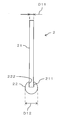
- FIG. 2 is a cross-sectional view showing a configuration example of the collector electrode 2.
- the collector electrode 2 includes a shaft portion 21 and a tip mounting portion 22 that can be attached to and detached from the shaft portion 21.
- the shaft portion 21 and the tip mounting portion 22 are made of, for example, stainless steel.
- the collector electrode 2 is not limited to stainless steel but can be formed using other various materials. Further, the shaft portion 21 and the tip attachment portion 22 may be formed using different materials.
- the shaft portion 21 is cantilevered in the cell chamber 11 along the direction of the axis L by being attached to the main body 1.
- a thread 211 is formed on the outer peripheral surface of the free end of the shaft portion 21 on the column outlet 31 side.
- the tip mounting portion 22 has a recess for inserting the shaft portion 21, and a thread groove 222 is formed on the inner wall surface of the recess.
- the tip mounting portion 22 can be attached to the shaft portion 21 by screwing the thread 211 of the shaft portion 21 into the thread groove 222 of the tip mounting portion 22.
- the tip mounting portion 22 is formed of a sphere having an outer diameter D12 larger than the outer diameter D11 of the shaft portion 21.
- the outer diameter D11 of the shaft portion 21 is, for example, about 1 to 2 mm, and the outer diameter D12 of the tip mounting portion 22 is, for example, about 3 to 5 mm.
- the outer diameter D12 of the tip mounting portion 22 is preferably about 1.5 to 5 times the outer diameter D11 of the shaft portion 21, and more preferably about 2 to 4 times.
- FIG. 3 is a diagram for explaining a change in sensitivity in the electron capture detector when the shape of the collector electrode 2 is changed.
- FIG. 3 shows the result of a test for confirming sensitivity with the horizontal axis representing the concentration of the measurement target component in the sample gas and the vertical axis representing the signal intensity obtained by the electron capture detector at each concentration.
- the voltage applied to the collector electrode 2 was constant regardless of the shape of the collector electrode 2.
- a small amount of measurement is performed by making the outer diameter D12 of the end on the column outlet 31 side of the collector electrode 2 in the cell chamber 11 larger than the outer diameter D11 of the other part. Even a sample gas containing a target component can be analyzed with high sensitivity. Even if the outer diameter D11 of the collector electrode 2 other than the end on the column outlet 31 side is increased, such an effect cannot be obtained, and the manufacturing cost is merely increased. Therefore, by increasing only the outer diameter D12 at the end on the column outlet 31 side, the sensitivity to the sample gas containing a trace amount of the measurement target component can be improved at low cost.
- the end portion on the column outlet 31 side of the collector electrode 2 into a spherical shape, it is possible to effectively improve the sensitivity to a sample gas containing a trace amount of a measurement target component.
- a voltage is applied to the collector electrode 2, an electric field is formed around the collector electrode 2, and this electric field is distributed according to the shape of the collector electrode 2.
- an electric field suitable for improving the sensitivity to the sample gas containing a trace amount of the measurement target component can be formed.
- the tip mounting portion 22 can be attached to and detached from the shaft portion 21 as necessary.
- the collector electrode 2 deteriorates due to contact with the sample gas
- the end on the column outlet 31 side near the column 3 is particularly likely to deteriorate. Therefore, the tip mounting portion 22 can be easily replaced by making the tip mounting portion 22 detachable from the shaft portion 21.
- the tip mounting portion 22 having a different shape can be attached to the shaft portion 21 depending on the type of sample gas, the sensitivity at the time of analysis, etc., a wide range of analysis can be performed in various modes. it can.
- the collector electrode 2 is not limited to the configuration in which the tip mounting portion 22 is detachably attached to the shaft portion 21 by screwing, and may be configured to be detachable in other manners.
- the part 22 may be formed integrally.
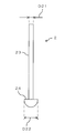
- FIG. 4A is a side view showing a first modification of the collector electrode 2.
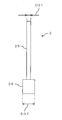
- FIG. 4B is a side view showing a second modification of the collector electrode 2.
- the collector electrode 2 is not limited to the shape shown in FIG. 1 and FIG. 2 as long as the outer diameter of the end on the column outlet 31 side is larger than the outer diameter of the other part.
- Various other shapes as exemplified in (1) can be adopted.
- FIG. 4A shows an example of a collector electrode 2 in which a rod-shaped shaft portion 23 having a cylindrical shape and a tip portion 24 having an outer diameter D22 larger than the outer diameter D21 of the shaft portion 23 are integrally formed.
- the tip 24 faces the column outlet 31 with the collector electrode 2 attached to the main body 1.
- only the surface on the column outlet 31 side at the tip 24 has a spherical shape (hemispherical shape).
- FIG. 4B shows an example of the collector electrode 2 in which a rod-shaped shaft portion 25 having a cylindrical shape and a tip portion 26 having an outer diameter D32 larger than the outer diameter D31 of the shaft portion 25 are integrally formed.
- the tip portion 26 faces the column outlet 31 with the collector electrode 2 attached to the main body 1.
- the tip end portion 26 is not configured to have a spherical shape, but is formed in a cylindrical shape.
- the end of the collector electrode 2 on the column outlet 31 side is not limited to the spherical shape, and can be formed in various other shapes.
- the tip portion 24 in FIG. 4A and the tip portion 26 in FIG. 4B may be configured to be detachable from the shaft portions 23 and 25, respectively, similarly to the configuration of the collector electrode 2 described in FIG.
- the tip portions 24 and 26 may be configured to be detachable by screwing with respect to the shaft portions 23 and 25, or may be configured to be detachable in other modes. Also good.
- the shaft portions 23 and 25 and the tip portions 24 and 26 are made of, for example, stainless steel. However, the configuration is not limited to this, and the shaft portions 23 and 25 and the tip portions 24 and 26 may be formed using a material other than stainless steel. In this case, the shaft portions 23 and 25 and the tip portions 24 and 26 may be formed using different materials.
- the configuration in which the collector electrode 2 and the outlet side end of the column 3 are arranged coaxially along the axis L has been described.
- the configuration is not limited to this, and at least one of the collector electrode 2 and the outlet side end of the column 3 may be disposed at a position shifted from the axis L. That is, the front end of the collector electrode 2 and the column outlet 31 are not limited to the configuration facing each other with an interval along the axis L, but are configured to oppose each other with a spacing along another direction. Also good.
Landscapes
- Chemical & Material Sciences (AREA)
- Health & Medical Sciences (AREA)
- General Health & Medical Sciences (AREA)
- Life Sciences & Earth Sciences (AREA)
- Analytical Chemistry (AREA)
- Biochemistry (AREA)
- Physics & Mathematics (AREA)
- General Physics & Mathematics (AREA)
- Immunology (AREA)
- Pathology (AREA)
- Toxicology (AREA)
- Chemical Kinetics & Catalysis (AREA)
- Electrochemistry (AREA)
- Other Investigation Or Analysis Of Materials By Electrical Means (AREA)
Abstract
微量の測定対象成分を含む試料ガスであっても高感度で分析を行うことができる電子捕獲検出器を提供する。セル室11内におけるコレクタ電極2のうち、カラム出口31側の端部の外径を、他の部分の外径よりも大きく形成する。これにより、微量の測定対象成分を含む試料ガスであっても高感度で分析を行うことができる。コレクタ電極2におけるカラム出口31側の端部以外の外径を大きくしても、このような効果を得ることはできず、単に製造コストが高くなるだけである。したがって、カラム出口31側の端部の外径のみを大きくすることにより、微量の測定対象成分を含む試料ガスに対する感度を低コストで向上することができる。
Description
本発明は、カラムからセル室に試料ガスを供給し、前記セル室内で放出される電子を捕獲することにより検出を行うための電子捕獲検出器に関するものである。
ガスクロマトグラフなどの分析装置に用いられる検出器の一例として、電子捕獲検出器(ECD:Electron Capture Detector)が知られている。この電子捕獲検出器の本体には、内部にセル室が形成されており、当該セル室内にコレクタ電極が配置されるとともに、カラム出口が接続されている(例えば、下記特許文献1参照)。
カラム出口からセル室内に供給される試料ガスは、例えば窒素ガスからなるメイクアップガスと混合される。セル室の内面には、63Niなどの放射性同位元素の線源が形成されており、メイクアップガスとしての窒素ガスに線源からβ線などの放射線が照射されることにより、電子を放出させることができる。
このようにして放出された電子をセル室内のコレクタ電極で捕獲することにより、基準電圧を得ることができるとともに、親電子性物質を測定対象成分として含む試料ガスがセル室内に供給された際には、親電子性物質に電子が取り込まれることに起因する電圧変動を検出することができる。
一般的な電子捕獲検出器では、セル室内において、カラム出口とコレクタ電極とが間隔を隔てて対向するように配置されている。具体的には、電子捕獲検出器の本体の一端側からセル室内にカラム出口が挿入されるとともに、他端側からセル室内にコレクタ電極が挿入されている。そして、カラム出口の先端部とコレクタ電極の先端部とが間隔を隔てて配置されることにより、カラム出口から供給される試料ガスが、セル室内で拡散しながらコレクタ電極に到達するようになっている。
しかしながら、従来の電子捕獲検出器では、微量の測定対象成分を含む試料ガスがカラム出口からセル室内に供給された場合に、十分な感度が得られず、測定対象成分の分析を良好に行うことができない場合があった。
本発明は、上記実情に鑑みてなされたものであり、微量の測定対象成分を含む試料ガスであっても高感度で分析を行うことができる電子捕獲検出器を提供することを目的とする。
本願発明者は、上記のような課題を解決するために、コレクタ電極を種々の形状に変更し、それぞれのコレクタ電極を用いて分析を行ったときの感度を確認する試験を繰り返し行った。従来の電子捕獲検出器では、コレクタ電極が円柱形状からなる棒状に形成されているが、試験の結果、コレクタ電極全体の外径を大きくしたり、小さくしたりしても、微量の測定対象成分を含む試料ガスに対する感度は向上しないことが分かった。
そこで、本願発明者は、コレクタ電極の先端部の形状に着目し、さらに検討を行った結果、コレクタ電極の先端部の外径を大きくすることにより、微量の測定対象成分を含む試料ガスに対する感度を向上させることができることを発見した。
本発明に係る電子捕獲検出器は、本体と、コレクタ電極とを備える。前記本体には、カラム出口から試料ガスが供給されるセル室が形成されている。前記コレクタ電極は、前記カラム出口に対して間隔を隔てて前記セル室内に配置され、前記セル室内で放出される電子を捕獲する。前記セル室内における前記コレクタ電極のうち、前記カラム出口側の端部の外径は、他の部分の外径よりも大きく形成されている。
このような構成によれば、セル室内におけるコレクタ電極のうち、カラム出口側の端部の外径を、他の部分の外径よりも大きくすることにより、微量の測定対象成分を含む試料ガスであっても高感度で分析を行うことができる。コレクタ電極におけるカラム出口側の端部以外の外径を大きくしても、このような効果を得ることはできず、単に製造コストが高くなるだけである。したがって、カラム出口側の端部の外径のみを大きくすることにより、微量の測定対象成分を含む試料ガスに対する感度を低コストで向上することができる。
前記コレクタ電極における前記カラム出口側の端部が球面形状を有していてもよい。
このような構成によれば、コレクタ電極におけるカラム出口側の端部を球面形状とすることにより、微量の測定対象成分を含む試料ガスに対する感度を効果的に向上することができる。コレクタ電極に電圧を印加すると、当該コレクタ電極の周囲に電界が形成されることとなるが、この電界はコレクタ電極の形状に応じた分布となる。コレクタ電極におけるカラム出口側の端部を球面形状とすれば、微量の測定対象成分を含む試料ガスに対する感度を向上するのに適した電界を形成することができる。
前記コレクタ電極は、前記セル室内に片持ち支持された軸部と、前記軸部における前記カラム出口側の自由端に着脱可能な先端取付部とを有していてもよい。この場合、前記先端取付部の外径が、前記軸部の外径よりも大きく形成されていてもよい。
このような構成によれば、必要に応じて、軸部に対して先端取付部を着脱することができる。コレクタ電極は、試料ガスとの接触により劣化するが、特にカラムに近いカラム出口側の端部が劣化しやすい。そこで、軸部に対して先端取付部を着脱可能とすることにより、先端取付部を容易に交換することができる。
これにより、コレクタ電極全体を交換する頻度を抑えることができるため、ランニングコストを低減することができる。また、試料ガスの種類や、必要とする分析時の感度などに応じて、形状の異なる先端取付部を軸部に取り付けることも可能であるため、種々の態様で幅広い分析を行うことができる。
本発明によれば、セル室内におけるコレクタ電極のうち、カラム出口側の端部の外径を、他の部分の外径よりも大きくすることにより、微量の測定対象成分を含む試料ガスであっても高感度で分析を行うことができる。
図1は、本発明の一実施形態に係る電子捕獲検出器の構成例を示した断面図である。この電子捕獲検出器は、例えばガスクロマトグラフなどの各種分析装置に用いることができる検出器であり、本体1と、当該本体1に取り付けられたコレクタ電極2とを備えている。
本体1は、例えば内部にセル室11が形成された円筒状の部材からなる。コレクタ電極2は、本体1における軸線L方向の一端部(図1における上端部)に取り付けられている。一方、本体1における軸線L方向の他端部(図1における下端部)には、カラム3の出口側端部が取り付けられている。
カラム3としては、例えばキャピラリカラムが用いられ、ヘリウムガスなどのキャリアガスに測定対象成分を含む試料ガスが、カラム出口31からセル室11内に供給される。ただし、カラム3は、キャピラリカラムに限られるものではなく、例えばパックドカラムであってもよい。
コレクタ電極2は、カラム出口31に対して間隔を隔ててセル室11内に配置されている。この例では、コレクタ電極2とカラム3の出口側端部とが軸線Lに沿って同軸上に配置されており、コレクタ電極2の先端とカラム出口31とが、軸線Lに沿って間隔を隔てて対向している。
本体1には、メイクアップガスを供給するためのメイクアップガス供給路12が形成されている。このメイクアップガス供給路12は、本体1内におけるカラム出口31の近傍に連通しており、メイクアップガス供給路12から供給されるメイクアップガスは、カラム出口31からの試料ガスと混合されてセル室11内に供給される。セル室11内の試料ガス及びメイクアップガスの混合ガスは、排気路13から排気される。
メイクアップガスとしては、例えば窒素ガスが用いられる。セル室11の内面には、63Niなどの放射性同位元素の線源14が形成されており、メイクアップガスとしての窒素ガスに線源14からβ線などの放射線が照射されることにより、電子を放出させることができるようになっている。
このようにして放出される電子は、セル室11内に挿入されたコレクタ電極2により捕獲することができる。これにより、基準電圧を得ることができるとともに、親電子性物質を測定対象成分として含む試料ガスがセル室11内に供給された際には、親電子性物質に電子が取り込まれることに起因する電圧変動を検出することができる。
本実施形態では、セル室11内におけるコレクタ電極2のうち、カラム出口31側の端部の外径が、他の部分の外径よりも大きく形成されている。より具体的には、コレクタ電極2におけるカラム出口31側の端部が球面形状を有している。
図2は、コレクタ電極2の構成例を示した断面図である。この例では、コレクタ電極2が、軸部21と、軸部21に対して着脱可能な先端取付部22とを有している。軸部21及び先端取付部22は、例えばステンレスにより形成されている。ただし、コレクタ電極2は、ステンレスに限らず、他の各種材料を用いて形成することができる。また、軸部21及び先端取付部22が、それぞれ異なる材料を用いて形成されていてもよい。
軸部21は、本体1に取り付けられることにより、軸線L方向に沿ってセル室11内に片持ち支持される。軸部21におけるカラム出口31側の自由端には、その外周面にねじ山211が形成されている。これに対して、先端取付部22には、軸部21を挿入するための凹部が形成されており、当該凹部の内壁面にねじ溝222が形成されている。これにより、軸部21のねじ山211を先端取付部22のねじ溝222にねじ込むようにして、先端取付部22を軸部21に取り付けることができるようになっている。
先端取付部22は、軸部21の外径D11よりも大きい外径D12を有する球体により形成されている。軸部21の外径D11は、例えば1~2mm程度であり、先端取付部22の外径D12は、例えば3~5mm程度である。先端取付部22の外径D12は、軸部21の外径D11の1.5~5倍程度であることが好ましく、2~4倍程度であればより好ましい。
図3は、コレクタ電極2の形状を変更した場合の電子捕獲検出器における感度の変化について説明するための図である。この図3では、試料ガス中における測定対象成分の濃度を横軸、各濃度において電子捕獲検出器により得られる信号強度を縦軸として、感度を確認する試験を行った結果が示されている。なお、コレクタ電極2に印加する電圧は、コレクタ電極2の形状にかかわらず一定とした。
従来のように、単なる円柱形状からなる棒状に形成されたコレクタ電極を用いた場合には、図3に破線で示すように、測定対象成分の濃度が低い領域と、測定対象成分の濃度が高い領域との双方において、感度が低くなる傾向があった。これに対して、図2に示すようなコレクタ電極2を用いた場合には、図3に実線で示すように、測定対象成分の濃度が低い領域と、測定対象成分の濃度が高い領域との双方において、感度が比較的高くなり、特に測定対象成分の濃度が低い領域で感度が非常に高くなることが分かった。
このように、本実施形態では、セル室11内におけるコレクタ電極2のうち、カラム出口31側の端部の外径D12を、他の部分の外径D11よりも大きくすることにより、微量の測定対象成分を含む試料ガスであっても高感度で分析を行うことができる。コレクタ電極2におけるカラム出口31側の端部以外の外径D11を大きくしても、このような効果を得ることはできず、単に製造コストが高くなるだけである。したがって、カラム出口31側の端部の外径D12のみを大きくすることにより、微量の測定対象成分を含む試料ガスに対する感度を低コストで向上することができる。
特に、コレクタ電極2におけるカラム出口31側の端部を球面形状とすることにより、微量の測定対象成分を含む試料ガスに対する感度を効果的に向上することができる。コレクタ電極2に電圧を印加すると、当該コレクタ電極2の周囲に電界が形成されることとなるが、この電界はコレクタ電極2の形状に応じた分布となる。コレクタ電極2におけるカラム出口31側の端部を球面形状とすれば、微量の測定対象成分を含む試料ガスに対する感度を向上するのに適した電界を形成することができる。
さらに、本実施形態では、必要に応じて、軸部21に対して先端取付部22を着脱することができる。コレクタ電極2は、試料ガスとの接触により劣化するが、特にカラム3に近いカラム出口31側の端部が劣化しやすい。そこで、軸部21に対して先端取付部22を着脱可能とすることにより、先端取付部22を容易に交換することができる。
これにより、コレクタ電極2全体を交換する頻度を抑えることができるため、ランニングコストを低減することができる。また、試料ガスの種類や、必要とする分析時の感度などに応じて、形状の異なる先端取付部22を軸部21に取り付けることも可能であるため、種々の態様で幅広い分析を行うことができる。
ただし、コレクタ電極2は、軸部21に対して先端取付部22がねじ込み式で着脱可能な構成に限らず、他の態様で着脱可能な構成であってもよいし、軸部21と先端取付部22とが一体的に形成された構成であってもよい。
図4Aは、コレクタ電極2の第1変形例を示した側面図である。図4Bは、コレクタ電極2の第2変形例を示した側面図である。コレクタ電極2は、カラム出口31側の端部の外径が他の部分の外径よりも大きく形成されていれば、図1及び図2に示すような形状に限らず、図4A及び図4Bに例示されるような他の各種形状を採用することができる。
図4Aには、円柱形状からなる棒状の軸部23と、軸部23の外径D21よりも大きい外径D22を有する先端部24とが、一体的に形成されたコレクタ電極2の例が示されている。先端部24は、コレクタ電極2を本体1に取り付けた状態でカラム出口31に対向する。この例では、先端部24におけるカラム出口31側の表面のみが球面形状(半球面形状)となっている。
図4Bには、円柱形状からなる棒状の軸部25と、軸部25の外径D31よりも大きい外径D32を有する先端部26とが、一体的に形成されたコレクタ電極2の例が示されている。先端部26は、コレクタ電極2を本体1に取り付けた状態でカラム出口31に対向する。この例では、先端部26が球面形状を有するような構成ではなく、円柱状に形成されている。このように、コレクタ電極2におけるカラム出口31側の端部は、球面形状に限らず、他の各種形状により形成することができる。
図4Aにおける軸部23の外径D21及び先端部24の外径D22の関係、並びに、図4Bにおける軸部25の外径D31及び先端部26の外径D32の関係は、図2において説明した軸部21の外径D11及び先端取付部22の外径D12の関係と同様の数値範囲を採用することが好ましい。
また、図4Aにおける先端部24及び図4Bにおける先端部26は、図2において説明したコレクタ電極2の構成と同様に、それぞれ軸部23,25に対して着脱可能な構成であってもよい。この場合、図2の場合と同様に、先端部24,26が軸部23,25に対してねじ込み式で着脱可能な構成であってもよいし、他の態様で着脱可能な構成であってもよい。
軸部23,25及び先端部24,26は、例えばステンレスにより形成されている。ただし、このような構成に限らず、軸部23,25及び先端部24,26が、ステンレス以外の材料を用いて形成されてもよい。この場合、軸部23,25及び先端部24,26が、それぞれ異なる材料を用いて形成されていてもよい。
以上の実施形態では、コレクタ電極2とカラム3の出口側端部とが軸線Lに沿って同軸上に配置された構成について説明した。しかし、このような構成に限らず、コレクタ電極2及びカラム3の出口側端部の少なくとも一方が軸線Lに対してずれた位置に配置されていてもよい。すなわち、コレクタ電極2の先端とカラム出口31とは、軸線Lに沿って間隔を隔てて対向するような構成に限らず、別の方向に沿って間隔を隔てて対向するような構成であってもよい。
1 本体
2 コレクタ電極
3 カラム
11 セル室
12 メイクアップガス供給路
13 排気路
14 線源
21 軸部
22 先端取付部
23 軸部
24 先端部
25 軸部
26 先端部
31 カラム出口
211 ねじ山
222 ねじ溝
2 コレクタ電極
3 カラム
11 セル室
12 メイクアップガス供給路
13 排気路
14 線源
21 軸部
22 先端取付部
23 軸部
24 先端部
25 軸部
26 先端部
31 カラム出口
211 ねじ山
222 ねじ溝
Claims (3)
- カラム出口から試料ガスが供給されるセル室が形成された本体と、
前記カラム出口に対して間隔を隔てて前記セル室内に配置され、前記セル室内で放出される電子を捕獲するコレクタ電極とを備え、
前記セル室内における前記コレクタ電極のうち、前記カラム出口側の端部の外径が、他の部分の外径よりも大きく形成されていることを特徴とする電子捕獲検出器。 - 前記コレクタ電極における前記カラム出口側の端部が球面形状を有していることを特徴とする請求項1に記載の電子捕獲検出器。
- 前記コレクタ電極は、前記セル室内に片持ち支持された軸部と、前記軸部における前記カラム出口側の自由端に着脱可能な先端取付部とを有し、
前記先端取付部の外径が、前記軸部の外径よりも大きく形成されていることを特徴とする請求項1又は2に記載の電子捕獲検出器。
Applications Claiming Priority (2)
| Application Number | Priority Date | Filing Date | Title |
|---|---|---|---|
| JP2014085549 | 2014-04-17 | ||
| JP2014-085549 | 2014-04-17 |
Publications (1)
| Publication Number | Publication Date |
|---|---|
| WO2015159463A1 true WO2015159463A1 (ja) | 2015-10-22 |
Family
ID=54323693
Family Applications (1)
| Application Number | Title | Priority Date | Filing Date |
|---|---|---|---|
| PCT/JP2014/084282 Ceased WO2015159463A1 (ja) | 2014-04-17 | 2014-12-25 | 電子捕獲検出器 |
Country Status (1)
| Country | Link |
|---|---|
| WO (1) | WO2015159463A1 (ja) |
Citations (5)
| Publication number | Priority date | Publication date | Assignee | Title |
|---|---|---|---|---|
| GB990251A (en) * | 1961-03-14 | 1965-04-28 | Hitachi Ltd | Gas detector for a gas chromatograph |
| JPS5183586A (ja) * | 1975-01-20 | 1976-07-22 | Hitachi Ltd | Kodenrigasukenshutsuki |
| JPS57100346A (en) * | 1980-12-15 | 1982-06-22 | Shimadzu Corp | Electron capturing type detector |
| JPH01146158U (ja) * | 1988-03-31 | 1989-10-09 | ||
| JPH11153579A (ja) * | 1997-11-20 | 1999-06-08 | Shimadzu Corp | エレクトロンキャプチャ検出器 |
-
2014
- 2014-12-25 WO PCT/JP2014/084282 patent/WO2015159463A1/ja not_active Ceased
Patent Citations (5)
| Publication number | Priority date | Publication date | Assignee | Title |
|---|---|---|---|---|
| GB990251A (en) * | 1961-03-14 | 1965-04-28 | Hitachi Ltd | Gas detector for a gas chromatograph |
| JPS5183586A (ja) * | 1975-01-20 | 1976-07-22 | Hitachi Ltd | Kodenrigasukenshutsuki |
| JPS57100346A (en) * | 1980-12-15 | 1982-06-22 | Shimadzu Corp | Electron capturing type detector |
| JPH01146158U (ja) * | 1988-03-31 | 1989-10-09 | ||
| JPH11153579A (ja) * | 1997-11-20 | 1999-06-08 | Shimadzu Corp | エレクトロンキャプチャ検出器 |
Similar Documents
| Publication | Publication Date | Title |
|---|---|---|
| JP5445353B2 (ja) | 放電イオン化電流検出器 | |
| US8921771B2 (en) | Corona discharge device and ion mobility spectrometer having corona discharge device | |
| CN105004709A (zh) | 一种液体放电微等离子体激发源装置及等离子体激发方法 | |
| CN103575839A (zh) | 一种高灵敏度光离子化检测器 | |
| CN105629285B (zh) | 一种多丝正比计数器 | |
| CN105869987B (zh) | 一种四极质谱仪 | |
| CN104576285B (zh) | 超低本底α电离室 | |
| EP3091564A1 (en) | Corona discharge assembly, ion mobility spectrometer, computer program, and storage medium | |
| JP5093377B2 (ja) | 電子捕獲検出器 | |
| WO2015159463A1 (ja) | 電子捕獲検出器 | |
| JP2012103219A5 (ja) | ||
| CN204696075U (zh) | 超低本底α电离室 | |
| JP2012103219A (ja) | 非接触型インピーダンスモニター | |
| KR20150090502A (ko) | 형광 분석용 디지털 엑스레이 소스 | |
| RU2016109229A (ru) | Способ определения плотности ионного тока на контактирующую с плазмой стенку и устройство для его осуществления | |
| CN205752097U (zh) | 一种四极质谱仪 | |
| CN201653975U (zh) | 一种β粒子三极电离粉尘传感器 | |
| US8188442B2 (en) | Non-radioactive electron capture detector for GC | |
| JP2013003070A (ja) | 放電イオン化電流検出器及びガスクロマトグラフ装置 | |
| CN105140095A (zh) | 用于光离子化检测挥发性气体的一维结构扩散型电离室 | |
| CN203786097U (zh) | 一种氦离子化检测器 | |
| RU94345U1 (ru) | Фотоионизационный детектор газов и паров | |
| Kolomiets et al. | Vortex focusing of ions produced in corona discharge | |
| JP2009198439A (ja) | 中性子位置測定装置 | |
| US9046460B2 (en) | Particle measuring apparatus and measuring method using the same |
Legal Events
| Date | Code | Title | Description |
|---|---|---|---|
| 121 | Ep: the epo has been informed by wipo that ep was designated in this application |
Ref document number: 14889752 Country of ref document: EP Kind code of ref document: A1 |
|
| NENP | Non-entry into the national phase |
Ref country code: DE |
|
| 122 | Ep: pct application non-entry in european phase |
Ref document number: 14889752 Country of ref document: EP Kind code of ref document: A1 |
|
| NENP | Non-entry into the national phase |
Ref country code: JP |