WO2015159443A1 - 流体圧シリンダ - Google Patents
流体圧シリンダ Download PDFInfo
- Publication number
- WO2015159443A1 WO2015159443A1 PCT/JP2014/066796 JP2014066796W WO2015159443A1 WO 2015159443 A1 WO2015159443 A1 WO 2015159443A1 JP 2014066796 W JP2014066796 W JP 2014066796W WO 2015159443 A1 WO2015159443 A1 WO 2015159443A1
- Authority
- WO
- WIPO (PCT)
- Prior art keywords
- rod
- piston
- cushion
- cylinder
- fluid pressure
- Prior art date
- Legal status (The legal status is an assumption and is not a legal conclusion. Google has not performed a legal analysis and makes no representation as to the accuracy of the status listed.)
- Ceased
Links
Images




Classifications
-
- F—MECHANICAL ENGINEERING; LIGHTING; HEATING; WEAPONS; BLASTING
- F15—FLUID-PRESSURE ACTUATORS; HYDRAULICS OR PNEUMATICS IN GENERAL
- F15B—SYSTEMS ACTING BY MEANS OF FLUIDS IN GENERAL; FLUID-PRESSURE ACTUATORS, e.g. SERVOMOTORS; DETAILS OF FLUID-PRESSURE SYSTEMS, NOT OTHERWISE PROVIDED FOR
- F15B15/00—Fluid-actuated devices for displacing a member from one position to another; Gearing associated therewith
- F15B15/20—Other details, e.g. assembly with regulating devices
- F15B15/22—Other details, e.g. assembly with regulating devices for accelerating or decelerating the stroke
-
- F—MECHANICAL ENGINEERING; LIGHTING; HEATING; WEAPONS; BLASTING
- F15—FLUID-PRESSURE ACTUATORS; HYDRAULICS OR PNEUMATICS IN GENERAL
- F15B—SYSTEMS ACTING BY MEANS OF FLUIDS IN GENERAL; FLUID-PRESSURE ACTUATORS, e.g. SERVOMOTORS; DETAILS OF FLUID-PRESSURE SYSTEMS, NOT OTHERWISE PROVIDED FOR
- F15B15/00—Fluid-actuated devices for displacing a member from one position to another; Gearing associated therewith
- F15B15/20—Other details, e.g. assembly with regulating devices
- F15B15/22—Other details, e.g. assembly with regulating devices for accelerating or decelerating the stroke
- F15B15/222—Other details, e.g. assembly with regulating devices for accelerating or decelerating the stroke having a piston with a piston extension or piston recess which throttles the main fluid outlet as the piston approaches its end position
-
- F—MECHANICAL ENGINEERING; LIGHTING; HEATING; WEAPONS; BLASTING
- F15—FLUID-PRESSURE ACTUATORS; HYDRAULICS OR PNEUMATICS IN GENERAL
- F15B—SYSTEMS ACTING BY MEANS OF FLUIDS IN GENERAL; FLUID-PRESSURE ACTUATORS, e.g. SERVOMOTORS; DETAILS OF FLUID-PRESSURE SYSTEMS, NOT OTHERWISE PROVIDED FOR
- F15B15/00—Fluid-actuated devices for displacing a member from one position to another; Gearing associated therewith
- F15B15/20—Other details, e.g. assembly with regulating devices
- F15B15/22—Other details, e.g. assembly with regulating devices for accelerating or decelerating the stroke
- F15B15/224—Other details, e.g. assembly with regulating devices for accelerating or decelerating the stroke having a piston which closes off fluid outlets in the cylinder bore by its own movement
-
- F—MECHANICAL ENGINEERING; LIGHTING; HEATING; WEAPONS; BLASTING
- F15—FLUID-PRESSURE ACTUATORS; HYDRAULICS OR PNEUMATICS IN GENERAL
- F15B—SYSTEMS ACTING BY MEANS OF FLUIDS IN GENERAL; FLUID-PRESSURE ACTUATORS, e.g. SERVOMOTORS; DETAILS OF FLUID-PRESSURE SYSTEMS, NOT OTHERWISE PROVIDED FOR
- F15B15/00—Fluid-actuated devices for displacing a member from one position to another; Gearing associated therewith
- F15B15/08—Characterised by the construction of the motor unit
- F15B15/14—Characterised by the construction of the motor unit of the straight-cylinder type
- F15B15/1423—Component parts; Constructional details
- F15B15/1433—End caps
-
- F—MECHANICAL ENGINEERING; LIGHTING; HEATING; WEAPONS; BLASTING
- F15—FLUID-PRESSURE ACTUATORS; HYDRAULICS OR PNEUMATICS IN GENERAL
- F15B—SYSTEMS ACTING BY MEANS OF FLUIDS IN GENERAL; FLUID-PRESSURE ACTUATORS, e.g. SERVOMOTORS; DETAILS OF FLUID-PRESSURE SYSTEMS, NOT OTHERWISE PROVIDED FOR
- F15B15/00—Fluid-actuated devices for displacing a member from one position to another; Gearing associated therewith
- F15B15/08—Characterised by the construction of the motor unit
- F15B15/14—Characterised by the construction of the motor unit of the straight-cylinder type
- F15B15/149—Fluid interconnections, e.g. fluid connectors, passages
-
- F—MECHANICAL ENGINEERING; LIGHTING; HEATING; WEAPONS; BLASTING
- F15—FLUID-PRESSURE ACTUATORS; HYDRAULICS OR PNEUMATICS IN GENERAL
- F15B—SYSTEMS ACTING BY MEANS OF FLUIDS IN GENERAL; FLUID-PRESSURE ACTUATORS, e.g. SERVOMOTORS; DETAILS OF FLUID-PRESSURE SYSTEMS, NOT OTHERWISE PROVIDED FOR
- F15B15/00—Fluid-actuated devices for displacing a member from one position to another; Gearing associated therewith
- F15B15/20—Other details, e.g. assembly with regulating devices
- F15B15/22—Other details, e.g. assembly with regulating devices for accelerating or decelerating the stroke
- F15B15/226—Other details, e.g. assembly with regulating devices for accelerating or decelerating the stroke having elastic elements, e.g. springs, rubber pads
-
- F—MECHANICAL ENGINEERING; LIGHTING; HEATING; WEAPONS; BLASTING
- F15—FLUID-PRESSURE ACTUATORS; HYDRAULICS OR PNEUMATICS IN GENERAL
- F15B—SYSTEMS ACTING BY MEANS OF FLUIDS IN GENERAL; FLUID-PRESSURE ACTUATORS, e.g. SERVOMOTORS; DETAILS OF FLUID-PRESSURE SYSTEMS, NOT OTHERWISE PROVIDED FOR
- F15B2211/00—Circuits for servomotor systems
- F15B2211/70—Output members, e.g. hydraulic motors or cylinders or control therefor
- F15B2211/705—Output members, e.g. hydraulic motors or cylinders or control therefor characterised by the type of output members or actuators
- F15B2211/7051—Linear output members
-
- F—MECHANICAL ENGINEERING; LIGHTING; HEATING; WEAPONS; BLASTING
- F15—FLUID-PRESSURE ACTUATORS; HYDRAULICS OR PNEUMATICS IN GENERAL
- F15B—SYSTEMS ACTING BY MEANS OF FLUIDS IN GENERAL; FLUID-PRESSURE ACTUATORS, e.g. SERVOMOTORS; DETAILS OF FLUID-PRESSURE SYSTEMS, NOT OTHERWISE PROVIDED FOR
- F15B2211/00—Circuits for servomotor systems
- F15B2211/70—Output members, e.g. hydraulic motors or cylinders or control therefor
- F15B2211/755—Control of acceleration or deceleration of the output member
Definitions
- the present invention relates to a fluid pressure cylinder for axially displacing a piston under supply action of pressure fluid, and more particularly, a fluid pressure cylinder having a cushion mechanism capable of cushioning an impact at a displacement end position of the piston.
- a fluid pressure cylinder for axially displacing a piston under supply action of pressure fluid
- a fluid pressure cylinder having a cushion mechanism capable of cushioning an impact at a displacement end position of the piston.
- a fluid pressure cylinder having a piston that is displaced under the action of supplying a pressure fluid for example, is used as a transport means for a work or the like.
- the applicant has proposed a fluid pressure cylinder provided with a cushion mechanism capable of cushioning an impact at a displacement end position of a piston as disclosed in Japanese Patent Laid-Open No. 2008-133920.
- the fluid pressure cylinder having this cushioning mechanism is provided with hollow cylindrical cushion rings on both end faces of the piston, and when the piston is displaced along the cylinder tube, the cushion ring is a recess in the head cover or a recess in the rod cover By inserting the valve, the flow rate of the fluid discharged from the port to the outside is reduced to reduce the displacement speed of the piston.
- a general object of the present invention is to provide a fluid pressure cylinder capable of reducing the manufacturing cost as well as shortening the manufacturing process.
- a cylinder tube having a cylinder chamber closed by a set of cover members, a piston internally mounted on the cylinder tube and displaced along the axial direction in the cylinder chamber, a pressure member formed on the cover member
- a fluid pressure cylinder having a port to be discharged and a rod mounted at an end along the axial direction of the piston and provided so as to be displaceable with the piston.
- the cover member is formed by casting and has a receiving hole in which a rod displaced with the piston is received, and the receiving hole is formed with a groove recessed with respect to the inner wall, and a ring-shaped holder into which the rod is inserted
- the groove portion is closed along the extending direction by being attached to the housing hole, and a passage for communicating the cylinder chamber and the port is configured.
- a cover member provided at the end of the cylinder tube Is formed by casting and has a receiving hole for receiving a rod displaced with the piston, and the receiving hole is formed with a groove recessed with respect to the inner wall surface, and the rod is inserted into the ring shape
- the cover member when the cover member is manufactured by casting, the groove portion is simultaneously formed, and by mounting the holder in the storage hole, the opening portion along the extending direction of the groove portion can be closed to be a passage.
- the passage can be easily formed, and accordingly, the manufacturing process can be shortened and the manufacturing cost can be reduced.
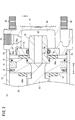
- FIG. 1 is an overall cross-sectional view of a fluid pressure cylinder according to an embodiment of the present invention.
- FIG. 2 is an enlarged sectional view showing the vicinity of a head cover in the fluid pressure cylinder of FIG.
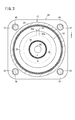
- FIG. 3 is a cross-sectional view taken along the line III-III of FIG.
- FIG. 4 is an exploded perspective view of the head cover.
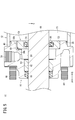
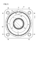
- FIG. 5 is an enlarged sectional view showing the vicinity of a rod cover in the fluid pressure cylinder of FIG. 6 is a cross-sectional view taken along the line VI-VI of FIG.
- FIG. 7 is an exploded perspective view of the rod cover.
- FIG. 8 is an overall sectional view showing a state in which the piston has moved to the rod cover side in the fluid pressure cylinder of FIG.
- the fluid pressure cylinder 10 comprises a cylindrical cylinder tube 12, a head cover (cover member) 14 attached to one end of the cylinder tube 12, and the cylinder tube 12 as shown in FIGS. 1 to 8. It includes a rod cover (cover member) 16 attached to the other end, and a piston 18 provided displaceably inside the cylinder tube 12.
- the cylinder tube 12 is, for example, a cylindrical body extending at a substantially constant diameter along the axial direction (the directions of arrows A and B), and a piston 18 is accommodated therein and closed by the head cover 14 and the rod cover 16 A cylinder chamber 20 is formed.
- the head cover 14 is formed, for example, by casting such as die-casting from a metal material such as aluminum alloy, and as shown in FIG. 3, at four corners formed in a rectangular shape in the axial direction (arrows A and B).
- a first through hole 22 is formed along and along.
- the head cover 14 is formed with a first stepped portion 24 which protrudes by a predetermined length from an end facing the rod cover 16 side (the direction of arrow A).
- One end of the cylinder tube 12 is held by being inserted into the side.
- a gasket 25 is provided between the first stepped portion 24 and the cylinder tube 12 to prevent leakage of the pressure fluid.
- a first port 26 extending in a direction perpendicular to the axis of the head cover 14 is formed on the outside of the head cover 14, and pressure fluid is supplied to and discharged from the first port 26 through a pipe (not shown). Ru.
- a first concave portion (housing hole) 28 having a circular cross section is formed with a predetermined depth so as to reach the cylinder tube 12 side (arrow A direction) at a central portion of the head cover 14.
- a first cushion chamber 30 in communication with the chamber is formed.
- the first cushion chamber 30 is formed at a position on the inner peripheral side of the first stepped portion 24.
- a ring-shaped first holder 32 is press-fitted and fixed to the first recess 28, and a first communication passage (passage) 34 recessed radially outward from the inner circumferential surface is formed.
- the first communication passage 34 is formed, for example, in a rectangular shape in cross section, and provided at a position in the first recess 28 substantially in the same direction as the opening direction of the first port 26.
- the first communication passage 34 includes a horizontal portion (first passage portion) 36 a extending in the same cross section along the axial direction (arrows A and B directions) from the opening of the first recess 28, and the first communication passage 34. It comprises a vertical portion (second passage portion) 38 a extending in the vertical direction (the direction of arrow C) from the end toward the center side of the first recess 28.
- the horizontal portion 36a communicates with the cylinder chamber 20 by opening to the cylinder chamber 20 side (the direction of the arrow A), and the lower end portion of the vertical portion 38a communicates with the first cushion chamber 30 described later.
- the cylinder chamber 20 of the cylinder tube 12 and the first cushion chamber 30 communicate with each other through the first communication passage 34.
- both the horizontal portion 36a and the vertical portion 38a are formed in a rectangular shape in cross section, but not limited to the rectangular shape in cross section, and may be formed in a semicircular shape in cross section.
- the first communication passage 34 is simultaneously formed when the head cover 14 is manufactured by casting, and is not formed by another process such as cutting after the head cover 14 is formed by casting.
- the first cushion chamber 30 is, for example, a space which is formed to be smaller in diameter and coaxial with the first recess 28 and closed by an end of the head cover 14.
- the first cushion chamber 30 communicates with the first port 26 provided on the outer peripheral side, and also communicates with the cylinder chamber 20 through the first communication passage 34.
- the first holder 32 is formed of an annular body having a first cushion hole (insertion hole) 40 at its center, and the outer peripheral surface of the first holder 32 is pressed by being pressed into the first recess 28.
- the first recess 28 is fitted and fixed to the inner circumferential surface of the recess 28. Further, the end surface of the first holder 32 is fixed so as to abut on the wall surface of the first recess 28.
- the inner peripheral side of the horizontal portion 36 a in the first communication passage 34 and the cylinder tube 12 side of the vertical portion 38 a respectively have the outer peripheral surface of the first holder 32.
- the end face is covered by the end face to form a passage of rectangular cross-section through which the pressure fluid flows.
- the first communication passage 34 is in the open state on the inner peripheral side of the head cover 14 and on the cylinder tube 12 side.
- a passage having a rectangular cross section in which each of the 12 sides is covered is configured.
- first cushion packing (seal member) 42 is attached to the first cushion hole 40 via an annular groove formed in the inner peripheral surface thereof.
- the first cushion packing 42 is annularly formed of, for example, an elastic material such as rubber, and is provided so as to protrude to the inner peripheral side with respect to the inner peripheral surface of the first cushion hole 40. Then, when a first cushion rod (rod) 78 described later is inserted into the first cushion hole 40, the outer peripheral surface of the first cushion rod 78 is in sliding contact with the first cushion packing 42.
- the rod cover 16 is formed, for example, by casting such as die casting from a metal material such as an aluminum alloy as in the head cover 14, and is formed in a rectangular shape in cross section. Second through holes 44 are formed at the four corners along the axial direction (arrows A and B) (see FIGS. 6 and 7). Further, the rod cover 16 is formed with a second stepped portion 46 which protrudes by a predetermined length from an end facing the head cover 14 side (arrow B direction), and the other end of the cylinder tube 12 is inserted on the outer peripheral side It is held by being done. A gasket 25 is provided on the outer peripheral side of the second stepped portion 46 between the second stepped portion 46 and the cylinder tube 12 to prevent leakage of the pressure fluid.
- the plurality of first and second The connecting rod 48 is inserted through the through holes 22 and 44, and a nut (not shown) is screwed on and tightened at both ends thereof.
- a nut (not shown) is screwed on and tightened at both ends thereof.
- a second port 50 extending in a direction perpendicular to the axis of the rod cover 16 is formed on the outside of the rod cover 16, and pressure fluid is supplied to the second port 50 through a pipe (not shown). ⁇ Is discharged.
- a second concave portion (housing hole) 52 having a circular cross section opened to face the cylinder tube 12 side (arrow B direction) and a second concave portion communicated with the second concave portion 52
- a cushion chamber 54 and a rod hole 56 communicating with the second cushion chamber 54 are formed.
- a ring-shaped second holder 58 is press-fitted and fixed, and a second communication passage (passage) 60 recessed radially outward from the inner circumferential surface is formed.
- the second communication passage 60 is formed, for example, in a rectangular shape in cross section, and provided at a position in the second recess 52 substantially in the same direction as the opening direction of the second port 50.
- the second communication passage 60 includes a horizontal portion (first passage portion) 36 b extending in the same cross section along the axial direction from the opening of the second recess 52, and the second recess 52 from the end of the horizontal portion 36 b. And a vertical portion (second passage portion) 38b extending in the vertical direction (the direction of the arrow C) toward the center side.
- the horizontal portion 36b communicates with the cylinder chamber 20 by opening to the cylinder chamber 20 side (the direction of the arrow B), and the lower end portion of the vertical portion 38b communicates with the second cushion chamber 54 described later.
- the cylinder chamber 20 of the cylinder tube 12 and the second cushion chamber 54 communicate with each other through the second communication passage 60.
- both the horizontal portion 36 b and the vertical portion 38 b are formed in a rectangular shape in cross section, the present invention is not limited to the case where the horizontal portion 36 b and the vertical portion 38 b are formed in a rectangular shape in cross section.
- the second communication passage 60 is formed at the same time when the rod cover 16 is manufactured by casting, and after the rod cover 16 is formed by casting, it is formed by another process such as cutting Absent.
- the second cushion chamber 54 is, for example, a space which is formed to be smaller in diameter and coaxial with the second recess 52 and is closed by the end of the rod cover 16.
- the second cushion chamber 54 communicates with the second port 50 provided on the outer peripheral side, and also communicates with the cylinder chamber 20 through the second communication passage 60.
- the rod hole 56 is adjacent to the second cushion chamber 54, and has a diameter smaller than that of the second cushion chamber 54, and is opened by penetrating to the other end of the rod cover 16 and a bush 62 is formed on the inner circumferential surface thereof. And a rod packing 64 is provided. Then, the bush 62 guides the piston rod 66 inserted in the rod hole 56 along the axial direction (arrows A and B directions), and the rod packing 64 passes between the piston rod 66 and the rod cover 16. Prevent leakage of pressure fluid.
- the second holder 58 is formed of an annular body having a second cushion hole (insertion hole) 68 at its center, and the second holder 58 is press-fit into the second recess 52 so that the outer peripheral surface thereof (2) The inner peripheral surface of the recess 52 is fitted and fixed. Further, the end face of the second holder 58 is fixed so as to abut on the wall surface of the second recess 52 provided at the boundary with the rod hole 56.
- the inner peripheral side of the horizontal portion 36b in the second communication passage 60 and the cylinder tube 12 side of the vertical portion 38b respectively have the outer peripheral surface of the second holder 58. And it is covered by the end face, and it becomes a passage through which pressure fluid flows.
- the second communication passage 60 is in the state where the inner peripheral side of the rod cover 16 and the cylinder tube 12 side are open, and the inner peripheral side and the cylinder tube A passage having a rectangular cross section in which each of the 12 sides is covered is configured.
- a second cushion packing (seal member) 70 is attached to the second cushion hole 68 through an annular groove formed on the inner peripheral surface thereof.
- the second cushion packing 70 is annularly formed of, for example, an elastic material such as rubber, and is provided so as to protrude to the inner peripheral side with respect to the inner peripheral surface of the second cushion hole 68. Then, when a second cushion rod (rod) 80 described later is inserted into the second cushion hole 68, the outer peripheral surface of the second cushion rod 80 is in sliding contact with the second cushion packing 70.
- the piston 18 is formed, for example, in a disk shape, as shown in FIGS. 1 and 8, and one end of a piston rod 66 is inserted and caulked in the center thereof to be integrally connected. Further, a piston packing 72, a magnetic body 74 and a wear ring 76 are mounted on the outer peripheral surface of the piston 18 via an annular groove.
- a first cushion rod 78 is coaxially formed on one end face of the piston 18 facing the head cover 14 and provided so as to protrude from the one end face by a predetermined length.
- the first cushion rod 78 is formed in a hollow shape having a hole 82 at the center, and the tip thereof is formed so as to gradually decrease in diameter in the direction of separating from the piston 18 (arrow B direction). .
- the first cushion rod 78 is not limited to the hollow shape, and may have a solid shape without the hole 82.
- a cylindrical second cushion rod 80 is provided on the other end surface side of the piston 18 facing the rod cover 16 so as to cover the outer peripheral side of the piston rod 66.
- the second cushion rod 80 is formed to project by a predetermined length with respect to the other end surface of the piston 18 and is gradually contracted in the direction (the arrow A direction) in which the tip is separated from the piston 18 It is formed to be diameter.
- a pair of dampers 84a and 84b are provided on the outer peripheral surfaces of the first and second cushion rods 78 and 80 so as to abut on one end surface and the other end surface of the piston 18, respectively.
- the dampers 84a and 84b are formed of, for example, an elastic material such as rubber or urethane, and are formed in a disk shape having holes through which the first and second cushion rods 78 and 80 can be inserted at the center thereof. Then, when the piston 18 is displaced along the axial direction (the directions of arrows A and B), the dampers 84 a and 84 b abut the end faces of the head cover 14 and the rod cover 16 to buffer the impact.
- the piston rod 66 comprises a shaft having a predetermined length along the axial direction (arrows A and B), one end of which is connected to the piston 18 and the other end is a rod hole 56 of the rod cover 16. And is displaceably supported by the bush 62. Further, a substantially central portion in the axial direction of the piston rod 66 is inserted into the second cushion hole 68 of the second holder 58.
- the fluid pressure cylinder 10 is basically configured as described above. Next, its operation and effects will be described.
- the piston 18 shown in FIG. 1 is displaced toward the head cover 14 (the direction of the arrow B), and the first cushion rod 78 is accommodated in the first cushion chamber 30 through the first holder 32 as an initial position. .
- pressure fluid is introduced into the first cushion chamber 30 by introducing pressure fluid from the pressure fluid source (not shown) into the first port 26.
- the second port 50 is open to the atmosphere under switching action by switching means (not shown).
- pressure fluid is supplied from the first cushion chamber 30 to the cylinder chamber 20 through the first communication passage 34 and to the hole 82 of the first cushion rod 78.
- the pressure fluid flows into the first cushion hole 40 to move the first cushion packing 42 toward the rod cover 16 (in the direction of the arrow A), and the cylinder is passed through the outer periphery of the first cushion packing 42. It circulates to the room 20 side.
- the air remaining in the cylinder chamber 20 between the piston 18 and the rod cover 16 flows into the second cushion chamber 54 through the second communication passage 60 and at the same time, the outer peripheral surface of the piston rod 66 and the After flowing into the second cushion chamber 54 through the gap between the second cushion packing 70 and the second cushion packing 70, the second cushion chamber 54 is discharged from the second port 50 to the outside.
- the piston 18 further moves toward the rod cover 16 (in the direction of the arrow A), whereby the other end of the piston rod 66 gradually protrudes to the outside of the rod cover 16 and the second cushion rod 80 It is inserted into the second cushion hole 68 of the second holder 58 from the front end, and the second cushion packing 70 is inserted while being in sliding contact with the outer peripheral surface thereof.
- the gap between the second cushion packing 70 of the second holder 58 and the piston rod 66 is closed by the second cushion rod 80, and the air in the cylinder chamber 20 passes through only the second communication passage 60 and the second port 50.
- the amount of discharge of air from the second port 50 is reduced, so that a part of the air is compressed in the cylinder chamber 20 to provide displacement resistance when the piston 18 is displaced.
- the cushioning function capable of reducing the displacement speed of the piston 18 functions.
- the piston 18 is gradually displaced toward the rod cover 16 (in the direction of the arrow A), the second cushion rod 80 is completely accommodated in the second cushion hole 68 and the second cushion chamber 54, and the damper 84b is By coming into contact with the end of the rod cover 16, the piston 18 comes to a displacement end position at which the piston 18 has reached the rod cover 16 (see FIG. 8).
- the second communication passage 60 is a fixed orifice for circulating the air in the cylinder chamber 20 toward the second port 50. Act as.
- the pressure fluid is supplied from the second cushion chamber 54 to the cylinder chamber 20 through the second communication passage 60 and flows into the second cushion hole 68 so that the second cushion packing 70 faces the head cover 14 (arrow It moves in the direction B) and flows to the side of the cylinder chamber 20 through the outer peripheral side of the second cushion packing 70.
- the piston 18 is pressed toward the head cover 14 (in the direction of the arrow B).
- the piston rod 66 is displaced together under the action of displacement of the piston 18, and while the second cushion rod 80 is in sliding contact with the second cushion packing 70 of the second holder 58, gradually from the second cushion chamber 54 to the cylinder chamber 20 side ( Move in the direction of arrow B).
- the air remaining in the cylinder chamber 20 between the piston 18 and the head cover 14 flows into the first cushion chamber 30 through the first communication passage 34 and at the same time, the first holder 32 is opened. After flowing into the first cushion chamber 30 through the first cushion hole 40, the air is discharged to the outside through the first port 26.
- the piston 18 further moves toward the head cover 14 (the direction of the arrow B), whereby the other end of the piston rod 66 is gradually stored in the rod hole 56 of the rod cover 16 and the first cushion rod 78 is inserted from the front end into the first cushion hole 40 of the first holder 32, and the first cushion packing 42 is inserted in sliding contact with the outer peripheral surface thereof.
- the first cushion hole 40 is closed by the first cushion rod 78, and the fluid in the cylinder chamber 20 is discharged to the first port 26 only through the first communication passage 34.
- the amount of air discharged from the first port 26 is reduced, and a part of the air is compressed in the cylinder chamber 20, It becomes a displacement resistance when the piston 18 is displaced.
- the displacement speed of the piston 18 gradually decreases as it approaches the initial position on the head cover 14 side (arrow B direction). That is, the cushioning function capable of reducing the displacement speed of the piston 18 functions.
- the piston 18 is gradually displaced toward the head cover 14 (the direction of the arrow B), the first cushion rod 78 is completely accommodated in the first cushion hole 40 and the first cushion chamber 30, and the damper 84a is the head cover.
- the piston 18 returns to the initial position where it has reached the head cover 14 (see FIG. 1).
- the first communication passage 34 is a fixed orifice for circulating the air in the cylinder chamber 20 to the first port 26 side. Act as.
- the head cover 14 and the rod cover 16 are formed by casting such as die casting and the first and second recesses formed therein.
- the first and second communication passages 34, 60 are formed respectively recessed with respect to the inner peripheral surfaces and end faces of the members 28, 52. And, by attaching the ring-shaped first and second holders 32 and 58 to the first and second recesses 28 and 52, an opening along the extending direction of the first and second communication paths 34 and 60 It is possible to form a rectangular passage in cross section which can close the portion and allow the cylinder chamber 20 and the first and second ports 26 and 50 to communicate with each other.
- the first and second holders 32, 58 can be assembled only by forming the groove-shaped first and second communication passages 34, 60 simultaneously.
- the first and second communication paths 34, 60 can be easily formed. Therefore, for example, compared with the case where the communication path is formed by cutting or the like after the head cover and the rod cover are manufactured, the manufacturing process can be shortened and the manufacturing cost can be reduced.
- the first and second communication passages 34, 60 are formed in the shape of a groove in which the inner peripheral side and the cylinder tube 12 side are open respectively, but the first and second recesses By mounting the ring-shaped first and second holders 32 and 58 to 28 and 52, respectively, the first and second series of rectangular cross sections which are closed on the inner peripheral side and the cylinder tube 12 side, respectively.
- the passages 34, 60 can be easily configured.
- first and second communication paths 34 and 60 can be easily formed simply by assembling the first and second holders 32 and 58 with the head cover 14 and the rod cover 16.
- the fluid pressure cylinder according to the present invention is, of course, not limited to the above embodiment, and various configurations can be adopted without departing from the scope of the present invention.
Landscapes
- Engineering & Computer Science (AREA)
- Physics & Mathematics (AREA)
- Fluid Mechanics (AREA)
- Mechanical Engineering (AREA)
- General Engineering & Computer Science (AREA)
- Actuator (AREA)
- Fluid-Damping Devices (AREA)
Abstract
Description
カバー部材は鋳造によって形成され、ピストンと共に変位するロッドが収納される収納穴を有し、収納穴には内壁面に対して窪んだ溝部が形成されると共に、ロッドの挿入されるリング状のホルダが収納穴に装着されることで溝部が延在方向に沿って塞がれ、シリンダ室とポートとを連通させる通路を構成することを特徴とする。
Claims (5)
- 一組のカバー部材(14、16)によって閉塞されたシリンダ室(20)を有するシリンダチューブ(12)と、該シリンダチューブ(12)に内装され、前記シリンダ室(20)内を軸方向に沿って変位するピストン(18)と、前記カバー部材(14、16)に形成され圧力流体の供給・排出されるポート(26、50)と、前記ピストン(18)の軸方向に沿った端部に装着され該ピストン(18)と共に変位自在に設けられるロッド(66)とを有した流体圧シリンダ(10)において、
前記カバー部材(14、16)は鋳造によって形成され、前記ピストン(18)と共に変位する前記ロッド(78、80)が収納される収納穴(28、52)を有し、前記収納穴(28、52)には内壁面に対して窪んだ溝部が形成されると共に、前記収納穴(28、52)に前記ロッド(78、80)の挿入されるリング状のホルダ(32、58)が装着されることで前記溝部が延在方向に沿って塞がれ、前記シリンダ室(20)と前記ポート(26、50)とを連通させる通路(34、60)を構成することを特徴とする流体圧シリンダ。 - 請求項1記載の流体圧シリンダにおいて、
前記通路(34、60)は、前記ピストン(18)の軸方向に沿って延在し、前記シリンダ室(20)と連通する第1通路部(36a、36b)と、
前記第1通路部(36a、36b)の端部に接続され、前記カバー部材(14、16)の内部と連通した第2通路部(38a、38b)と、
を有することを特徴とする流体圧シリンダ。 - 請求項1記載の流体圧シリンダにおいて、
前記ホルダ(32、58)は、前記収納穴(28、52)に対して圧入されることを特徴とする流体圧シリンダ。 - 請求項1記載の流体圧シリンダにおいて、
前記溝部は、断面矩形状又は断面半円状に形成されることを特徴とする流体圧シリンダ。 - 請求項2記載の流体圧シリンダにおいて、
前記通路(34、60)は、前記第1通路部(36a、36b)と前記第2通路部(38a、38b)とが略直交するように接続されたL字状に形成されることを特徴とする流体圧シリンダ。
Priority Applications (7)
| Application Number | Priority Date | Filing Date | Title |
|---|---|---|---|
| MX2016013314A MX2016013314A (es) | 2014-04-14 | 2014-06-25 | Cilindro de presion de fluido. |
| RU2016139685A RU2649735C9 (ru) | 2014-04-14 | 2014-06-25 | Гидро (пневмо) цилиндр |
| CN201480077984.1A CN106211788B (zh) | 2014-04-14 | 2014-06-25 | 流体压力缸 |
| DE112014006457.2T DE112014006457B4 (de) | 2014-04-14 | 2014-06-25 | Fluiddruckzylinder |
| KR1020167031694A KR101889342B1 (ko) | 2014-04-14 | 2014-06-25 | 유체압 실린더 |
| BR112016023147A BR112016023147A2 (pt) | 2014-04-14 | 2014-06-25 | cilindro de pressão de fluido |
| US15/301,911 US10352337B2 (en) | 2014-04-14 | 2014-06-25 | Fluid pressure cylinder |
Applications Claiming Priority (2)
| Application Number | Priority Date | Filing Date | Title |
|---|---|---|---|
| JP2014-082618 | 2014-04-14 | ||
| JP2014082618A JP6159938B2 (ja) | 2014-04-14 | 2014-04-14 | 流体圧シリンダ |
Publications (1)
| Publication Number | Publication Date |
|---|---|
| WO2015159443A1 true WO2015159443A1 (ja) | 2015-10-22 |
Family
ID=54323679
Family Applications (1)
| Application Number | Title | Priority Date | Filing Date |
|---|---|---|---|
| PCT/JP2014/066796 Ceased WO2015159443A1 (ja) | 2014-04-14 | 2014-06-25 | 流体圧シリンダ |
Country Status (10)
| Country | Link |
|---|---|
| US (1) | US10352337B2 (ja) |
| JP (1) | JP6159938B2 (ja) |
| KR (1) | KR101889342B1 (ja) |
| CN (1) | CN106211788B (ja) |
| BR (1) | BR112016023147A2 (ja) |
| DE (1) | DE112014006457B4 (ja) |
| MX (1) | MX2016013314A (ja) |
| RU (1) | RU2649735C9 (ja) |
| TW (1) | TWI606186B (ja) |
| WO (1) | WO2015159443A1 (ja) |
Cited By (1)
| Publication number | Priority date | Publication date | Assignee | Title |
|---|---|---|---|---|
| CN105465096A (zh) * | 2015-12-31 | 2016-04-06 | 东莞积信制造有限公司 | 一种液压油缸 |
Families Citing this family (9)
| Publication number | Priority date | Publication date | Assignee | Title |
|---|---|---|---|---|
| JP6606807B2 (ja) * | 2017-03-08 | 2019-11-20 | Smc株式会社 | 軸連結構造及び流体圧装置 |
| DE102017003017A1 (de) | 2017-03-29 | 2018-10-04 | Wabco Gmbh | Aktuator für ein automatisiertes oder automatisches Schaltgetriebe und Verfahren zur Steuerung dieses Aktuators |
| JP6903844B2 (ja) * | 2018-09-12 | 2021-07-14 | Smc株式会社 | 流体圧シリンダ |
| CN110131236A (zh) * | 2019-05-30 | 2019-08-16 | 海盐新星机电有限公司 | 一种缓冲效果好的多层密封油缸 |
| CN110848196B (zh) * | 2019-11-28 | 2021-11-23 | 河南航天液压气动技术有限公司 | 一种液压控制阀 |
| US11319972B1 (en) * | 2021-05-11 | 2022-05-03 | Caterpillar Inc. | Hydraulic cylinder snubbing retention arrangement |
| KR102496202B1 (ko) * | 2021-12-10 | 2023-02-06 | (주)플로우버스 | 척력을 이용한 충격 완화장치 |
| US20230287905A1 (en) * | 2022-03-11 | 2023-09-14 | Deere & Company | Spring dampening for accumulator system |
| TWI836723B (zh) * | 2022-11-15 | 2024-03-21 | 達見綜合工業股份有限公司 | 具縮回緩衝之雙動缸 |
Citations (5)
| Publication number | Priority date | Publication date | Assignee | Title |
|---|---|---|---|---|
| JPS4813692U (ja) * | 1971-07-03 | 1973-02-15 | ||
| JPH11230117A (ja) * | 1998-02-18 | 1999-08-27 | Kayaba Ind Co Ltd | 流体圧シリンダ |
| JPH11294414A (ja) * | 1998-03-04 | 1999-10-26 | Buemach Eng Internatl Bv | 行程終位置の制動構成体 |
| JP2002266813A (ja) * | 2001-03-13 | 2002-09-18 | Taiyo Ltd | 流体圧シリンダ用のシリンダカバーおよび流体圧シリンダ |
| JP2010266054A (ja) * | 2009-05-18 | 2010-11-25 | Smc Corp | 流体圧シリンダ |
Family Cites Families (19)
| Publication number | Priority date | Publication date | Assignee | Title |
|---|---|---|---|---|
| US2751886A (en) * | 1953-05-06 | 1956-06-26 | Petch Mfg Company | Air cylinder |
| FR1370356A (fr) * | 1963-09-28 | 1964-08-21 | Vérin à coussins amortisseurs | |
| US3267815A (en) * | 1965-10-21 | 1966-08-23 | Ortman Miller Machine Company | Cushioning structure for power cylinders |
| BE759771A (fr) | 1969-12-03 | 1971-05-17 | Sandoz Sa | Colorants azoiques peu solubles |
| US4088061A (en) * | 1973-11-07 | 1978-05-09 | Kurt Stoll | Piston/cylinder assemblies |
| FR2422848A1 (fr) * | 1978-04-14 | 1979-11-09 | Outillage Air Comprime | Dispositif d'amortissement et de demarrage de verins |
| US4296675A (en) * | 1979-07-16 | 1981-10-27 | Aeroquip Corporation | Cylinder cushion with contractable ring |
| SU1125423A1 (ru) * | 1983-11-09 | 1984-11-23 | Предприятие П/Я А-1477 | Цилиндр с торможением |
| SU1645671A1 (ru) * | 1987-02-18 | 1991-04-30 | Московское научно-производственное объединение по строительному и дорожному машиностроению "ВНИИстройдормаш" | Демпфирующее устройство дл гидроцилиндров |
| US4794681A (en) * | 1987-08-27 | 1989-01-03 | Bimba Manufacturing Company | Fluid cylinder cushioning system |
| DE3807889A1 (de) * | 1988-03-10 | 1989-09-21 | Festo Kg | Druckmittelbetaetigbare schlittenartige vorschubeinrichtung |
| JP4054990B2 (ja) * | 2003-03-07 | 2008-03-05 | Smc株式会社 | シリンダ装置 |
| RU47063U1 (ru) * | 2005-05-23 | 2005-08-10 | Закрытое акционерное общество "Кыштымский медеэлектролитный завод" | Гидроцилиндр |
| JP2008133920A (ja) | 2006-11-29 | 2008-06-12 | Smc Corp | 流体圧シリンダ |
| CN101598156B (zh) | 2009-06-17 | 2012-03-14 | 江苏恒立高压油缸股份有限公司 | 浮动式缓冲油缸 |
| JP5862098B2 (ja) * | 2011-08-04 | 2016-02-16 | Smc株式会社 | 流体圧シリンダ |
| CN102588385B (zh) * | 2012-02-14 | 2015-01-07 | 宁波亚德客自动化工业有限公司 | 气缸节流缓冲一体化结构 |
| CN102705299A (zh) * | 2012-05-17 | 2012-10-03 | 太仓奥科机械设备有限公司 | 气缸缓冲装置 |
| JP6028994B2 (ja) * | 2012-06-18 | 2016-11-24 | Smc株式会社 | 流体圧シリンダ |
-
2014
- 2014-04-14 JP JP2014082618A patent/JP6159938B2/ja active Active
- 2014-06-25 RU RU2016139685A patent/RU2649735C9/ru active
- 2014-06-25 MX MX2016013314A patent/MX2016013314A/es unknown
- 2014-06-25 DE DE112014006457.2T patent/DE112014006457B4/de active Active
- 2014-06-25 WO PCT/JP2014/066796 patent/WO2015159443A1/ja not_active Ceased
- 2014-06-25 BR BR112016023147A patent/BR112016023147A2/pt active Search and Examination
- 2014-06-25 KR KR1020167031694A patent/KR101889342B1/ko active Active
- 2014-06-25 CN CN201480077984.1A patent/CN106211788B/zh active Active
- 2014-06-25 US US15/301,911 patent/US10352337B2/en active Active
- 2014-06-27 TW TW103122231A patent/TWI606186B/zh not_active IP Right Cessation
Patent Citations (5)
| Publication number | Priority date | Publication date | Assignee | Title |
|---|---|---|---|---|
| JPS4813692U (ja) * | 1971-07-03 | 1973-02-15 | ||
| JPH11230117A (ja) * | 1998-02-18 | 1999-08-27 | Kayaba Ind Co Ltd | 流体圧シリンダ |
| JPH11294414A (ja) * | 1998-03-04 | 1999-10-26 | Buemach Eng Internatl Bv | 行程終位置の制動構成体 |
| JP2002266813A (ja) * | 2001-03-13 | 2002-09-18 | Taiyo Ltd | 流体圧シリンダ用のシリンダカバーおよび流体圧シリンダ |
| JP2010266054A (ja) * | 2009-05-18 | 2010-11-25 | Smc Corp | 流体圧シリンダ |
Cited By (1)
| Publication number | Priority date | Publication date | Assignee | Title |
|---|---|---|---|---|
| CN105465096A (zh) * | 2015-12-31 | 2016-04-06 | 东莞积信制造有限公司 | 一种液压油缸 |
Also Published As
| Publication number | Publication date |
|---|---|
| RU2649735C1 (ru) | 2018-04-04 |
| TW201538859A (zh) | 2015-10-16 |
| RU2649735C9 (ru) | 2018-06-07 |
| JP6159938B2 (ja) | 2017-07-12 |
| US10352337B2 (en) | 2019-07-16 |
| DE112014006457B4 (de) | 2024-02-22 |
| TWI606186B (zh) | 2017-11-21 |
| KR20160143824A (ko) | 2016-12-14 |
| MX2016013314A (es) | 2017-01-18 |
| KR101889342B1 (ko) | 2018-08-17 |
| JP2015203443A (ja) | 2015-11-16 |
| BR112016023147A2 (pt) | 2017-10-10 |
| CN106211788A (zh) | 2016-12-07 |
| CN106211788B (zh) | 2019-04-09 |
| DE112014006457T5 (de) | 2016-12-01 |
| US20170152873A1 (en) | 2017-06-01 |
Similar Documents
| Publication | Publication Date | Title |
|---|---|---|
| WO2015159444A1 (ja) | 流体圧シリンダ | |
| WO2015159443A1 (ja) | 流体圧シリンダ | |
| CN101191509B (zh) | 流体压力缸 | |
| KR101945788B1 (ko) | 유체압 실린더 | |
| US10030786B2 (en) | Adjustable damping valve arrangement | |
| WO2017069049A1 (ja) | アキュムレータ | |
| US10316868B2 (en) | Fluid pressure cylinder | |
| EP3221596B1 (en) | Damper sleeve and pneumatic cylinder | |
| CN109642594B (zh) | 流体操纵式膜片驱动器和配备其的阀组件 | |
| US10145440B2 (en) | Pressure buffer device and damping force generating member | |
| TWI547658B (zh) | 用於直線運動裝置之損耗環 | |
| JP6796291B2 (ja) | エアシリンダ | |
| JP4464259B2 (ja) | 減圧弁 | |
| CN108138812A (zh) | 流体压力装置及其制造方法 | |
| JP5483559B2 (ja) | 磁気粘性流体流動型ダンパ | |
| JP3227400U (ja) | 流体圧シリンダ |
Legal Events
| Date | Code | Title | Description |
|---|---|---|---|
| 121 | Ep: the epo has been informed by wipo that ep was designated in this application |
Ref document number: 14889679 Country of ref document: EP Kind code of ref document: A1 |
|
| WWE | Wipo information: entry into national phase |
Ref document number: 15301911 Country of ref document: US |
|
| WWE | Wipo information: entry into national phase |
Ref document number: MX/A/2016/013314 Country of ref document: MX Ref document number: 112014006457 Country of ref document: DE |
|
| ENP | Entry into the national phase |
Ref document number: 2016139685 Country of ref document: RU Kind code of ref document: A |
|
| WWE | Wipo information: entry into national phase |
Ref document number: IDP00201606885 Country of ref document: ID |
|
| ENP | Entry into the national phase |
Ref document number: 20167031694 Country of ref document: KR Kind code of ref document: A |
|
| 122 | Ep: pct application non-entry in european phase |
Ref document number: 14889679 Country of ref document: EP Kind code of ref document: A1 |
|
| REG | Reference to national code |
Ref country code: BR Ref legal event code: B01A Ref document number: 112016023147 Country of ref document: BR |
|
| ENP | Entry into the national phase |
Ref document number: 112016023147 Country of ref document: BR Kind code of ref document: A2 Effective date: 20161004 |