WO2015159396A1 - 光源装置及び表示装置 - Google Patents
光源装置及び表示装置 Download PDFInfo
- Publication number
- WO2015159396A1 WO2015159396A1 PCT/JP2014/060858 JP2014060858W WO2015159396A1 WO 2015159396 A1 WO2015159396 A1 WO 2015159396A1 JP 2014060858 W JP2014060858 W JP 2014060858W WO 2015159396 A1 WO2015159396 A1 WO 2015159396A1
- Authority
- WO
- WIPO (PCT)
- Prior art keywords
- guide plate
- light
- light guide
- optical sheet
- display panel
- Prior art date
- Legal status (The legal status is an assumption and is not a legal conclusion. Google has not performed a legal analysis and makes no representation as to the accuracy of the status listed.)
- Ceased
Links
Images



Classifications
-
- G—PHYSICS
- G02—OPTICS
- G02B—OPTICAL ELEMENTS, SYSTEMS OR APPARATUS
- G02B6/00—Light guides; Structural details of arrangements comprising light guides and other optical elements, e.g. couplings
- G02B6/0001—Light guides; Structural details of arrangements comprising light guides and other optical elements, e.g. couplings specially adapted for lighting devices or systems
- G02B6/0011—Light guides; Structural details of arrangements comprising light guides and other optical elements, e.g. couplings specially adapted for lighting devices or systems the light guides being planar or of plate-like form
- G02B6/0033—Means for improving the coupling-out of light from the light guide
- G02B6/005—Means for improving the coupling-out of light from the light guide provided by one optical element, or plurality thereof, placed on the light output side of the light guide
- G02B6/0053—Prismatic sheet or layer; Brightness enhancement element, sheet or layer
-
- G—PHYSICS
- G02—OPTICS
- G02B—OPTICAL ELEMENTS, SYSTEMS OR APPARATUS
- G02B6/00—Light guides; Structural details of arrangements comprising light guides and other optical elements, e.g. couplings
- G02B6/0001—Light guides; Structural details of arrangements comprising light guides and other optical elements, e.g. couplings specially adapted for lighting devices or systems
- G02B6/0011—Light guides; Structural details of arrangements comprising light guides and other optical elements, e.g. couplings specially adapted for lighting devices or systems the light guides being planar or of plate-like form
- G02B6/0013—Means for improving the coupling-in of light from the light source into the light guide
- G02B6/0023—Means for improving the coupling-in of light from the light source into the light guide provided by one optical element, or plurality thereof, placed between the light guide and the light source, or around the light source
- G02B6/0031—Reflecting element, sheet or layer
-
- G—PHYSICS
- G02—OPTICS
- G02B—OPTICAL ELEMENTS, SYSTEMS OR APPARATUS
- G02B6/00—Light guides; Structural details of arrangements comprising light guides and other optical elements, e.g. couplings
- G02B6/0001—Light guides; Structural details of arrangements comprising light guides and other optical elements, e.g. couplings specially adapted for lighting devices or systems
- G02B6/0011—Light guides; Structural details of arrangements comprising light guides and other optical elements, e.g. couplings specially adapted for lighting devices or systems the light guides being planar or of plate-like form
- G02B6/0033—Means for improving the coupling-out of light from the light guide
- G02B6/005—Means for improving the coupling-out of light from the light guide provided by one optical element, or plurality thereof, placed on the light output side of the light guide
- G02B6/0051—Diffusing sheet or layer
-
- G—PHYSICS
- G02—OPTICS
- G02B—OPTICAL ELEMENTS, SYSTEMS OR APPARATUS
- G02B6/00—Light guides; Structural details of arrangements comprising light guides and other optical elements, e.g. couplings
- G02B6/0001—Light guides; Structural details of arrangements comprising light guides and other optical elements, e.g. couplings specially adapted for lighting devices or systems
- G02B6/0011—Light guides; Structural details of arrangements comprising light guides and other optical elements, e.g. couplings specially adapted for lighting devices or systems the light guides being planar or of plate-like form
- G02B6/0033—Means for improving the coupling-out of light from the light guide
- G02B6/005—Means for improving the coupling-out of light from the light guide provided by one optical element, or plurality thereof, placed on the light output side of the light guide
- G02B6/0055—Reflecting element, sheet or layer
-
- G—PHYSICS
- G02—OPTICS
- G02B—OPTICAL ELEMENTS, SYSTEMS OR APPARATUS
- G02B6/00—Light guides; Structural details of arrangements comprising light guides and other optical elements, e.g. couplings
- G02B6/0001—Light guides; Structural details of arrangements comprising light guides and other optical elements, e.g. couplings specially adapted for lighting devices or systems
- G02B6/0011—Light guides; Structural details of arrangements comprising light guides and other optical elements, e.g. couplings specially adapted for lighting devices or systems the light guides being planar or of plate-like form
- G02B6/0081—Mechanical or electrical aspects of the light guide and light source in the lighting device peculiar to the adaptation to planar light guides, e.g. concerning packaging
- G02B6/0085—Means for removing heat created by the light source from the package
-
- G—PHYSICS
- G02—OPTICS
- G02B—OPTICAL ELEMENTS, SYSTEMS OR APPARATUS
- G02B6/00—Light guides; Structural details of arrangements comprising light guides and other optical elements, e.g. couplings
- G02B6/0001—Light guides; Structural details of arrangements comprising light guides and other optical elements, e.g. couplings specially adapted for lighting devices or systems
- G02B6/0011—Light guides; Structural details of arrangements comprising light guides and other optical elements, e.g. couplings specially adapted for lighting devices or systems the light guides being planar or of plate-like form
- G02B6/0081—Mechanical or electrical aspects of the light guide and light source in the lighting device peculiar to the adaptation to planar light guides, e.g. concerning packaging
- G02B6/0086—Positioning aspects
- G02B6/0088—Positioning aspects of the light guide or other optical sheets in the package
-
- G—PHYSICS
- G02—OPTICS
- G02F—OPTICAL DEVICES OR ARRANGEMENTS FOR THE CONTROL OF LIGHT BY MODIFICATION OF THE OPTICAL PROPERTIES OF THE MEDIA OF THE ELEMENTS INVOLVED THEREIN; NON-LINEAR OPTICS; FREQUENCY-CHANGING OF LIGHT; OPTICAL LOGIC ELEMENTS; OPTICAL ANALOGUE/DIGITAL CONVERTERS
- G02F1/00—Devices or arrangements for the control of the intensity, colour, phase, polarisation or direction of light arriving from an independent light source, e.g. switching, gating or modulating; Non-linear optics
- G02F1/01—Devices or arrangements for the control of the intensity, colour, phase, polarisation or direction of light arriving from an independent light source, e.g. switching, gating or modulating; Non-linear optics for the control of the intensity, phase, polarisation or colour
- G02F1/13—Devices or arrangements for the control of the intensity, colour, phase, polarisation or direction of light arriving from an independent light source, e.g. switching, gating or modulating; Non-linear optics for the control of the intensity, phase, polarisation or colour based on liquid crystals, e.g. single liquid crystal display cells
- G02F1/133—Constructional arrangements; Operation of liquid crystal cells; Circuit arrangements
- G02F1/1333—Constructional arrangements; Manufacturing methods
- G02F1/133308—Support structures for LCD panels, e.g. frames or bezels
-
- G—PHYSICS
- G02—OPTICS
- G02F—OPTICAL DEVICES OR ARRANGEMENTS FOR THE CONTROL OF LIGHT BY MODIFICATION OF THE OPTICAL PROPERTIES OF THE MEDIA OF THE ELEMENTS INVOLVED THEREIN; NON-LINEAR OPTICS; FREQUENCY-CHANGING OF LIGHT; OPTICAL LOGIC ELEMENTS; OPTICAL ANALOGUE/DIGITAL CONVERTERS
- G02F1/00—Devices or arrangements for the control of the intensity, colour, phase, polarisation or direction of light arriving from an independent light source, e.g. switching, gating or modulating; Non-linear optics
- G02F1/01—Devices or arrangements for the control of the intensity, colour, phase, polarisation or direction of light arriving from an independent light source, e.g. switching, gating or modulating; Non-linear optics for the control of the intensity, phase, polarisation or colour
- G02F1/13—Devices or arrangements for the control of the intensity, colour, phase, polarisation or direction of light arriving from an independent light source, e.g. switching, gating or modulating; Non-linear optics for the control of the intensity, phase, polarisation or colour based on liquid crystals, e.g. single liquid crystal display cells
- G02F1/133—Constructional arrangements; Operation of liquid crystal cells; Circuit arrangements
- G02F1/1333—Constructional arrangements; Manufacturing methods
- G02F1/133308—Support structures for LCD panels, e.g. frames or bezels
- G02F1/133317—Intermediate frames, e.g. between backlight housing and front frame
-
- G—PHYSICS
- G02—OPTICS
- G02F—OPTICAL DEVICES OR ARRANGEMENTS FOR THE CONTROL OF LIGHT BY MODIFICATION OF THE OPTICAL PROPERTIES OF THE MEDIA OF THE ELEMENTS INVOLVED THEREIN; NON-LINEAR OPTICS; FREQUENCY-CHANGING OF LIGHT; OPTICAL LOGIC ELEMENTS; OPTICAL ANALOGUE/DIGITAL CONVERTERS
- G02F1/00—Devices or arrangements for the control of the intensity, colour, phase, polarisation or direction of light arriving from an independent light source, e.g. switching, gating or modulating; Non-linear optics
- G02F1/01—Devices or arrangements for the control of the intensity, colour, phase, polarisation or direction of light arriving from an independent light source, e.g. switching, gating or modulating; Non-linear optics for the control of the intensity, phase, polarisation or colour
- G02F1/13—Devices or arrangements for the control of the intensity, colour, phase, polarisation or direction of light arriving from an independent light source, e.g. switching, gating or modulating; Non-linear optics for the control of the intensity, phase, polarisation or colour based on liquid crystals, e.g. single liquid crystal display cells
- G02F1/133—Constructional arrangements; Operation of liquid crystal cells; Circuit arrangements
- G02F1/1333—Constructional arrangements; Manufacturing methods
- G02F1/133308—Support structures for LCD panels, e.g. frames or bezels
- G02F1/13332—Front frames
Definitions
- the present invention relates to a light source device including a light guide plate that emits light incident from a light source near one side surface from one surface, an optical sheet disposed to face the one surface of the light guide plate, and a display device including the light source device.
- a light source device including a light guide plate that emits light incident from a light source near one side surface from one surface, an optical sheet disposed to face the one surface of the light guide plate, and a display device including the light source device.
- Patent Document 1 a recess that extends from the LED light source block to at least a part of the light guide plate / reflective sheet is provided at the end of the panel frame where the LED light source block is disposed.
- a reflective heat insulating member that extends from the end portion to at least a part of the light guide plate / reflective sheet and is fixed to the panel frame, the light extraction efficiency is improved and the deterioration of the optical member is suppressed.
- a liquid crystal display device having good optical characteristics is disclosed.
- the present invention has been made in view of such circumstances, and an object of the present invention is to provide a light guide plate that emits light incident from a light source on one side surface from one surface, and to be disposed opposite to the one surface of the light guide plate.
- a distance maintaining unit is provided along a side surface of the light guide plate, and one end portion is interposed between the optical sheet and the light guide plate to maintain a distance between the optical sheet and the light guide plate.
- a light source device capable of preventing a shadow of the interval maintaining portion from being reflected on a display panel provided on the front side of the optical sheet by making the one end portion of the interval maintaining portion white It is providing a display apparatus provided with a light source device.
- a light source device includes: a light guide plate that emits light incident from a light source on one side surface from one surface; and an optical sheet disposed to face the one surface of the light guide plate. Provided along the side surface, and having an end portion interposed between the optical sheet and the light guide plate to maintain an interval between the optical sheet and the light guide plate. It is white.
- the one end portion of the gap maintaining portion is white, the light emitted from the light guide plate is reflected by the one end portion or travels through the one end portion. Therefore, when the display panel is provided on the front side of the optical sheet, the interval maintaining portion is not shaded.
- the light source device is characterized in that the gap maintaining portion is provided continuously with the one end portion and has an attachment portion provided outside the light guide plate, and the attachment portion is black. To do.
- the mounting portion is black, it is possible to prevent light from the light source or the light guide plate from becoming so-called leakage light and leaking outside the device.
- the light source device includes a buffer member provided between one end of the interval maintaining unit and the light guide plate, and a different color boundary of the interval maintaining unit is located at a contact portion with the buffer member. It is comprised as follows.
- the different color boundary of the gap maintaining portion is configured to be located at the contact portion with the buffer member, the problem of shadows on the display panel as described above, and light leakage Can solve the problem that occurs.
- a display device includes the light source device according to any of the above-described inventions, and a display panel that displays an image using light incident through the optical sheet.
- the light emitted from the light source device enters the display panel via the optical sheet.
- the display panel displays an image using incident light.
- the one end interposed between the optical sheet and the light guide plate is white, so that the shadow of the interval maintaining unit is reflected on the display panel provided on the front side of the optical sheet. This can be prevented in advance.
- FIG. 1 is a front view showing an appearance of a television receiver according to an embodiment of the present invention.
- Reference numeral 100 in the figure indicates a television receiver according to an embodiment of the present invention.
- the horizontal direction in the drawing is referred to as the horizontal direction
- the vertical direction in the drawing is called the vertical direction.
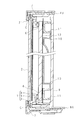
- FIG. 2 is a longitudinal sectional view taken along line AA in FIG.
- the television receiver 100 includes a rectangular liquid crystal display panel 2 that displays an image on one surface of the front side.
- a light source device 1 for irradiating the liquid crystal display panel 2 with light is disposed on the back side of the liquid crystal display panel 2.
- the light source device 1 includes a light source unit 3, an optical sheet 4, and a light guide plate 5.
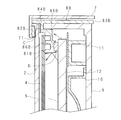
- 3 is an enlarged view in which the lower part is enlarged in the longitudinal sectional view of FIG. 2
- FIG. 4 is an enlarged view in which the upper part is enlarged in the longitudinal sectional view of FIG.
- FIG. 5 is a cross-sectional view of the end portion in the horizontal direction of the television receiver 100 according to the embodiment of the present invention.
- the optical sheet 4 is arranged so that one surface thereof faces the other surface of the liquid crystal display panel 2, and the light guide plate 5 is arranged so that one surface faces the other surface of the optical sheet 4. Further, the reflection sheet 12 is arranged so that the other surface of the light guide plate 5 faces the other surface.
- a front cover 7 is disposed on the edge side of the liquid crystal display panel 2.
- the front cover 7 has a hollow rectangular display window 71 that follows the shape of one surface of the liquid crystal display panel 2 visually recognized by the user. The user can visually recognize an image displayed on the one surface of the liquid crystal display panel 2 through the display window 71.
- the liquid crystal display panel 2 is covered with a display window 71 at a peripheral portion of the one surface. More specifically, the display window 71 presses the peripheral edge of the liquid crystal display panel 2 against the light guide plate 5 through the cushion C provided along the peripheral edge of the one surface of the liquid crystal display panel 2, thereby the liquid crystal display panel. 2 is held.
- the liquid crystal display panel 2 is provided with a polarizing plate (not shown) on the other surface, and light incident using the polarizing plate is converted into a P wave (horizontal deflection component) and an S wave (vertical deflection component). The P wave is separated, and only the P wave goes out to one side, and the S wave is absorbed by the polarizing plate.
- the liquid crystal display panel 2 may be an electrophoretic liquid crystal panel, for example.
- the optical sheet 4 which is emitted from the light source unit 3, diffuses and collects light incident on the light guide plate 5 and emits more uniform light toward the liquid crystal display panel 2.
- the optical sheet 4 includes two diffusion sheets and one prism sheet, and the prism sheet is interposed between the two diffusion sheets.
- One diffusion sheet disposed on the light guide plate 5 side of the two diffusion sheets is an optical sheet that diffuses light incident from the light source unit 3 through the light guide plate 5 and enters the prism sheet.
- the prism sheet is an optical sheet that collects light incident through the one diffusion sheet and emits the light toward another diffusion sheet. The light that has passed through the prism sheet is incident on the other diffusion sheet perpendicular to the prism sheet.
- the other diffusion sheet disposed on the liquid crystal display panel 2 side further diffuses the light incident through the prism sheet to obtain a more uniform luminance distribution.
- the optical sheet is emitted toward
- a rectangular light guide plate 5 is arranged on the other surface side of the optical sheet 4.
- the light guide plate 5 guides light emitted from the light source unit 3 to the optical sheet 4 (liquid crystal display panel 2).
- the light guide plate 5 is configured so that one surface facing the other surface of the optical sheet 4 has an emission surface on which a pattern is formed so that light incident from the light source unit 3 travels in the direction of the liquid crystal display panel 2. May be. Accordingly, the light guide plate 5 can uniformly transmit the light incident from the light source unit 3 to the optical sheet 4 through the emission surface by changing the light into flat light.
- the light guide plate 5 is made of, for example, highly transparent acrylic resin, and a reflective sheet 12 is disposed on the other surface side of the light guide plate 5. That is, one surface of the reflection sheet 12 faces the light guide plate 5 and the other surface.
- the reflection sheet 12 is slightly larger than the light guide plate 5 and has a rectangular shape following the light guide plate 5. Further, the reflection sheet 12 diffuses light incident on the light guide plate 5 from the light source unit 3 from the other surface side of the light guide plate 5 and emits the light through the emission surface of the light guide plate 5.
- the spacer 11 is disposed on the other surface side of the reflection sheet 12 and on the edge of the reflection sheet 12. In other words, the edge of the reflection sheet 12 is supported by the spacer 11, and the distance from the heat sink 9 described later is kept constant.
- the spacer 11 has a bowl shape, and the outer side of the bottom is in contact with the other surface of the reflection sheet 12.
- a so-called backlight chassis 10 is arranged on the other surface side of the reflection sheet 12 except for the edge (hereinafter, a surplus portion).
- the surplus portion of the reflection sheet 12 is supported by the backlight chassis 10 from the other surface side.
- the backlight chassis 10 has a bowl shape, and the outer side of the bottom is in contact with the surplus portion of the reflection sheet 12.
- the spacer 11 and the backlight chassis 10 keep the distance between the reflective sheet 12 (light guide plate 5) and the heat sink 9 constant.
- the heat sink 9 is disposed so as to face the spacer 11 and the inside of the backlight chassis 10.
- the heat sink 9 is made of aluminum having excellent thermal conductivity, for example.
- One side of the heat sink 9 is in contact with the spacer 11 and the backlight chassis 10.
- the heat radiating plate 9 has a box shape having a rectangular bottom that follows the light guide plate 5, and the bottom has substantially the same dimensions as the light guide plate 5. Moreover, the heat sink 9 has a side wall portion that rises from each edge of the bottom toward the light guide plate 5. Among the side wall portions, the side wall portion 91 on the light source unit 3 side is provided along the other surface on the other surface side of the substrate 32 of the light source unit 3 to be described later. In other words, the side wall portion 91 is interposed between the gap maintaining portion 8 described later and the substrate 32.
- the television receiver 100 includes the interval maintaining unit 8 that holds each of the liquid crystal display panel 2, the optical sheet 4, and the light guide plate 5 at a predetermined interval.
- the interval maintaining unit 8 is provided along the edges of the liquid crystal display panel 2, the optical sheet 4, and the light guide plate 5.
- the interval maintaining unit 8 includes a lower edge in the vertical direction, that is, a lower interval maintaining unit 8A provided in the vicinity of the light source unit 3, an upper interval maintaining unit 8B provided in the upper edge, and the end in the horizontal direction.
- the horizontal interval maintaining unit 8C is provided.
- the lower interval maintaining portion 8 ⁇ / b> A has a crank shape in a longitudinal sectional view, and has a mounting portion 82 ⁇ / b> A having two bent portions.
- the attachment portion 82 ⁇ / b> A is provided near the end portions of the light guide plate 5 and the optical sheet 4.
- the lower interval maintaining portion 8A is connected to one end portion of the attachment portion 82A, and has a distal end portion 81A interposed between the light guide plate 5 and the optical sheet 4 on the light guide plate 5 side from the attachment portion 82A.
- a leg plate 83A extending from the other end portion in the thickness direction of the light guide plate 5 is provided at the other end portion of the attachment portion 82A.
- the mounting portion 82 ⁇ / b> A and the leg plate 83 ⁇ / b> A form a hook shape in a longitudinal sectional view and engage with the tip of the side wall portion 91 of the heat radiating plate 9, whereby the lower interval maintaining portion 8 ⁇ / b> A is held by the heat radiating plate 9.
- the mounting portion 82A has a two-stage bent portion in a longitudinal sectional view, and a flat portion is formed at the other end portion and one end portion.
- the flat part 84A at the other end is provided with an end on the light source part 3 side of the liquid crystal display panel 2 with a cushion interposed therebetween.
- the end portion of the liquid crystal display panel 2 is sandwiched by the display window 71 of the front cover 7 and the flat portion 84A of the lower interval maintaining portion 8A via the cushion C.
- the mounting portion 82A and the leg plate 83A are, for example, black. Moreover, it is not restricted to this, What is necessary is just an achromatic color which can absorb light.
- a tip 81A (one end) is connected to one end of the mounting portion 82A. More specifically, a distal end portion 81A projects from the edge of the flat portion at the one end of the mounting portion 82A on the optical sheet 4 side. The tip 81A is in contact with the other surface of the optical sheet 4 at the tip.
- the distal end portion 81A is, for example, white. Moreover, it is not restricted to this, What is necessary is just an achromatic color which can reflect light.
- a groove 85A is formed on the side surface of the light guide plate 5 so as to straddle the different color boundary.
- the cushion 6 is disposed on the edge of one surface of the light guide plate 5 so as to engage with the groove 85A.
- the different color boundary is configured to exist at a contact position with the cushion 6 (buffer member). More specifically, in the thickness direction of the light guide plate 5, the position of the different color boundary is configured to match the position of the cushion 6. Also, the groove 85A can prevent the cushion 6 from being displaced.
- the liquid crystal display panel 2 is sandwiched between the display window 71 of the front cover 7 and the flat portion 84A of the lower interval maintaining portion 8A, and the optical sheet 4 is supported by the distal end of the distal end portion 81A of the lower interval maintaining portion 8A.
- the liquid crystal display panel 2, the optical sheet 4, and the light guide plate 5 can be held while maintaining a constant interval in these parallel directions.
- a so-called two-color molding method is further used for molding the lower interval maintaining unit 8A.
- Such a two-color molding method is a known technique capable of obtaining a product having a plurality of colors by sequentially performing injection using a plurality of nozzles at the time of injection molding, and detailed description thereof is omitted here. .
- the light source part 3 is provided in the lower part in the vertical direction and near one side surface of the light guide plate 5.
- the light source unit 3 includes a strip-shaped substrate 32 disposed to face the one side surface of the light guide plate 5 and a plurality of light sources 31, 31,... Mounted on one surface of the substrate 32 along the longitudinal direction of the substrate 32. ..31.
- the light source 31 includes, for example, a cold cathode fluorescent lamp (CCFL: Cold Cathode Fluorescence Lamp), an external electrode fluorescent lamp (EEFL: External Electrode Fluorescent Lamp), a hot cathode tube (HCFL: Hot Cathode Fluorescent LED). Emitting (Diode) etc.
- CCFL Cold Cathode Fluorescence Lamp
- EFL External Electrode Fluorescent Lamp
- HCFL Hot Cathode Fluorescent LED.
- the lower interval maintaining unit 8A since the lower interval maintaining unit 8A has the above-described configuration, the lower interval maintaining unit is provided in the liquid crystal display panel 2 while maintaining a certain interval between the liquid crystal display panel 2, the optical sheet 4, and the light guide plate 5. 8A shadows can be prevented from being reflected.
- the distal end portion 81A of the lower distance maintaining portion 8A which is the center side of the light guide plate 5 from the cushion 6, is white, the light emitted from one surface of the light guide plate 5 is reflected by the distal end portion 81A or the distal end portion. It passes through 81A and does not leak outside the light guide plate 5 from the cushion 6 (see the solid arrow in FIG. 3). Therefore, it is possible to prevent the user viewing the image displayed on the liquid crystal display panel 2 from feeling uncomfortable because the shadow of the lower interval maintaining unit 8A is not reflected on the liquid crystal display panel 2.
- the lower distance maintaining unit 8A since the lower distance maintaining unit 8A has the above-described configuration, the light emitted from the light source 31 or reflected by the substrate 32 leaks from the joint of the front cover 7 or the liquid crystal display panel 2. It is possible to prevent leakage light.
- the attachment portion 82A of the lower interval maintaining portion 8A that is outside the light guide plate 5 from the cushion 6 is black, the light that causes the leakage light is absorbed and shielded by the attachment portion 82A, and the front cover 7 or There is no leakage to the outside from the joint of the liquid crystal display panel 2 (see the dashed arrow in FIG. 3).
- the position of the different color boundary is not aligned with the position of the cushion 6 in the thickness direction of the light guide plate 5 and is located closer to the center of the light guide plate 5 than the cushion 6, the shadow caused by the absorption of light by the black portion. Is reflected on the display panel 2. Moreover, when it is located outside the light plate 5 from the cushion 6, light leakage becomes intense due to reflection by the white portion.
- the display panel 2 is shaded. Both the problem of reflection and the problem of leakage light can be solved.
- the upper interval maintaining portion 8B has a crank shape in a longitudinal sectional view, and has an attachment portion 82B having two-stage bent portions.
- the attachment portion 82 ⁇ / b> B is provided near the end portions of the light guide plate 5 and the optical sheet 4.
- the upper gap maintaining portion 8B is provided continuously with one end portion of the attachment portion 82B, and has a front end portion 81B (one end portion) disposed on the center side of the light guide plate 5 with respect to the attachment portion 82B. That is, the distal end portion 81 ⁇ / b> B is interposed between the light guide plate 5 and the optical sheet 4.
- a leg plate 83B disposed in parallel with the thickness direction of the light guide plate 5 is provided at the other end of the attachment portion 82B.
- the leg plate 83 ⁇ / b> B has a strip shape, the dimension in the longitudinal direction is approximately the same as the dimension in the longitudinal direction of the liquid crystal display panel 2, and the dimension in the lateral direction is approximately equal to the thickness of the television receiver 100.
- the attachment portion 82B and the leg plate 83B form a hook shape in a longitudinal cross-sectional view and are engaged with the front end of the side wall portion of the heat radiating plate 9, whereby the upper space maintaining portion 8B is held by the heat radiating plate 9.
- the front edge is in contact with the inside of the front cover 7.
- the mounting portion 82B has a two-stage bent portion in a longitudinal sectional view, and a flat portion is formed at the other end portion and one end portion.
- the flat portion 84B at the other end is provided with an end on the light source 3 side of the liquid crystal display panel 2 with a cushion interposed therebetween.
- the end portion of the liquid crystal display panel 2 is sandwiched by the display window 71 of the front cover 7 and the flat portion 84B of the upper interval maintaining portion 8B via the cushion C.
- an elongated rectangular support plate 86B is protruded from the flat portion of the one end portion of the attachment portion 82B toward the optical sheet 4.
- the support plate 86 ⁇ / b> B has a long side dimension that is substantially the same as the long side dimension of the optical sheet 4, and abuts against the other surface of the optical sheet 4 at the long side end to support the optical sheet 4.
- the mounting portion 82B and the leg plate 83B are, for example, black. Moreover, it is not restricted to this, What is necessary is just an achromatic color which can absorb light.
- a tip 81B is continuously provided at one end of the mounting portion 82B. More specifically, a tip end portion 81B projects from the edge of the flat portion at the one end of the mounting portion 82B to the optical sheet 4 side. The front end portion 81B is in contact with the other surface of the optical sheet 4 at the front end, like the support plate 86B.
- the distal end portion 81B is, for example, white. Moreover, it is not restricted to this, What is necessary is just an achromatic color which can reflect light.
- the flat portion at the one end of the attachment portion 82B has a black boundary between the black color of the attachment portion 82B and the white color of the tip portion 81B. More specifically, the different color boundary is formed between the support plate 86B and the tip portion 81B.
- a groove 85B is formed on the side surface of the light guide plate 5 so as to straddle the different color boundary. That is, the groove 85B is formed on the side surface of the light guide plate 5 having such a flat portion and at an intermediate position between the support plate 86B and the distal end portion 81B.
- the cushion 6 is disposed on one edge of the light guide plate 5 so as to engage with the groove 85B.
- the different color boundary is configured to exist at a contact position with the cushion 6. More specifically, in the thickness direction of the light guide plate 5, the position of the different color boundary is configured to match the position of the cushion 6. Further, the groove 85B can prevent the cushion 6 from being displaced.
- the liquid crystal display panel 2 is sandwiched between the display window 71 of the front cover 7 and the flat portion 84B of the upper interval maintaining portion 8B, and the optical sheet 4 is supported by the support plate 86B and the distal end portion 81B of the upper interval maintaining portion 8B. Therefore, the liquid crystal display panel 2, the optical sheet 4, and the light guide plate 5 can be held while maintaining a constant interval in the juxtaposed direction.
- the upper interval maintaining unit 8B since the upper interval maintaining unit 8B has the above-described configuration, the upper interval maintaining unit is provided in the liquid crystal display panel 2 while maintaining a certain interval between the liquid crystal display panel 2, the optical sheet 4, and the light guide plate 5. It is possible to prevent the shadow of 8B from appearing (see the solid arrow in FIG. 4).
- the upper distance maintaining portion 8B since the upper distance maintaining portion 8B has the above-described configuration, the light from the side surface of the light guide plate 5 does not become the leakage light, but is absorbed and shielded by the mounting portion 82B, and the front cover 7 Alternatively, light does not leak outside from the joint of the liquid crystal display panel 2 (see the broken arrow in FIG. 4).
- the lateral distance maintaining portion 8 ⁇ / b> C has a mounting portion 82 ⁇ / b> C that has a crank shape in a longitudinal sectional view.
- the attachment portion 82 ⁇ / b> C is provided near the end portions of the light guide plate 5 and the optical sheet 4.
- the lateral spacing maintaining portion 8C is connected to one end portion of the attachment portion 82C, and is located at the center side of the light guide plate 5 from the attachment portion 82C and interposed between the light guide plate 5 and the optical sheet 4.
- a portion 81C is provided.
- a leg plate 83C extending from the other end portion in the thickness direction of the light guide plate 5 is provided at the other end portion of the attachment portion 82C.
- the mounting portion 82 ⁇ / b> C and the leg plate 83 ⁇ / b> C form a hook shape in a longitudinal sectional view and engage with the front end of the side wall portion of the heat radiating plate 9, whereby the lateral spacing maintaining portion 8 ⁇ / b> C is held by the heat radiating plate 9.
- the mounting portion 82C has a flat portion at the other end and one end.
- the flat portion 84C at the other end is provided with an end portion on the light source portion 3 side of the liquid crystal display panel 2 with a cushion interposed therebetween.
- the end portion of the liquid crystal display panel 2 is sandwiched by the display window 71 of the front cover 7 and the flat portion 84C of the lateral interval maintaining portion 8C via the cushion C. Yes.
- the mounting portion 82C and the leg plate 83C are, for example, black. Moreover, it is not restricted to this, What is necessary is just an achromatic color which can absorb light.
- a distal end portion 81C (one end portion) is connected to one end portion of the mounting portion 82C, and the distal end portion 81C has the same shape as the above-described distal end portion 81A.
- the different color boundary is configured to exist at a position where the cushion 6 is in contact. That is, in the thickness direction of the light guide plate 5, the position of the different color boundary is configured to match the position of the cushion 6.
- the horizontal interval maintaining unit 8C can also prevent the shadow of the horizontal interval maintaining unit 8C from appearing on the liquid crystal display panel 2 (see the solid line arrow in FIG. 5). Further, light from the side surface of the light guide plate 5 does not become leakage light, and light can be prevented from leaking outward from the joint of the front cover 7 or the liquid crystal display panel 2 (see the broken arrow in FIG. 5).
Landscapes
- Physics & Mathematics (AREA)
- General Physics & Mathematics (AREA)
- Optics & Photonics (AREA)
- Nonlinear Science (AREA)
- Mathematical Physics (AREA)
- Chemical & Material Sciences (AREA)
- Crystallography & Structural Chemistry (AREA)
- Planar Illumination Modules (AREA)
- Liquid Crystal (AREA)
Abstract
Description
2 液晶表示パネル
3 光源部(光源)
4 光学シート
5 導光板
6 クッション(緩衝部材)
8A 下方間隔維持部
8B 上方間隔維持部
8C 横方間隔維持部
81A、81B、81C 先端部(一端部)
82A、82B、82C 取付部
100 テレビジョン受像機
Claims (4)
- 一側面の光源から入射される光を一面から出射させる導光板と、該導光板の前記一面と対向配置された光学シートとを備える光源装置において、
前記導光板の側面に沿って設けられ、前記光学シート及び導光板の間に一端部が介在して該光学シート及び導光板間の間隔を維持する間隔維持部を備えており、
該間隔維持部は前記一端部が白色であることを特徴とする光源装置。 - 前記間隔維持部は、前記一端部に連設され、前記導光板の外側に設けられた取付部を有しており、該取付部が黒色であることを特徴とする請求項1に記載の光源装置。
- 前記間隔維持部の一端部と、前記導光板との間に設けられた緩衝部材を備え、
前記間隔維持部の異色境界が前記緩衝部材との接触部分に位置するように構成されていることを特徴とする請求項2に記載の光源装置。 - 請求項1から3の何れかに記載の光源装置と、
前記光学シートを介して入射される光を用いて画像を表示する表示パネルと
を備えることを特徴とする表示装置。
Priority Applications (4)
| Application Number | Priority Date | Filing Date | Title |
|---|---|---|---|
| CN201480076598.0A CN106068478B (zh) | 2014-04-16 | 2014-04-16 | 光源装置和显示装置 |
| PCT/JP2014/060858 WO2015159396A1 (ja) | 2014-04-16 | 2014-04-16 | 光源装置及び表示装置 |
| JP2016513552A JP6230697B2 (ja) | 2014-04-16 | 2014-04-16 | 光源装置及び表示装置 |
| US15/121,707 US9874677B2 (en) | 2014-04-16 | 2014-04-16 | Light source device and display apparatus |
Applications Claiming Priority (1)
| Application Number | Priority Date | Filing Date | Title |
|---|---|---|---|
| PCT/JP2014/060858 WO2015159396A1 (ja) | 2014-04-16 | 2014-04-16 | 光源装置及び表示装置 |
Publications (1)
| Publication Number | Publication Date |
|---|---|
| WO2015159396A1 true WO2015159396A1 (ja) | 2015-10-22 |
Family
ID=54323638
Family Applications (1)
| Application Number | Title | Priority Date | Filing Date |
|---|---|---|---|
| PCT/JP2014/060858 Ceased WO2015159396A1 (ja) | 2014-04-16 | 2014-04-16 | 光源装置及び表示装置 |
Country Status (4)
| Country | Link |
|---|---|
| US (1) | US9874677B2 (ja) |
| JP (1) | JP6230697B2 (ja) |
| CN (1) | CN106068478B (ja) |
| WO (1) | WO2015159396A1 (ja) |
Families Citing this family (4)
| Publication number | Priority date | Publication date | Assignee | Title |
|---|---|---|---|---|
| KR102429136B1 (ko) * | 2015-10-30 | 2022-08-03 | 엘지디스플레이 주식회사 | 디스플레이 장치 |
| KR102382506B1 (ko) * | 2017-10-24 | 2022-04-05 | 삼성전자주식회사 | 디스플레이 장치 |
| CN109709709A (zh) * | 2017-10-25 | 2019-05-03 | 深圳富泰宏精密工业有限公司 | 显示器 |
| EP4123247B1 (en) * | 2021-07-21 | 2025-06-25 | LG Electronics Inc. | Door assembly |
Citations (4)
| Publication number | Priority date | Publication date | Assignee | Title |
|---|---|---|---|---|
| JP2010073506A (ja) * | 2008-09-19 | 2010-04-02 | Hitachi Ltd | 液晶表示装置及びこれを用いた映像表示装置 |
| JP2013114811A (ja) * | 2011-11-25 | 2013-06-10 | Minebea Co Ltd | 面状照明装置およびその作製方法 |
| JP2013246439A (ja) * | 2012-05-29 | 2013-12-09 | Young Lighting Technology Inc | 表示装置 |
| JP2014006352A (ja) * | 2012-06-22 | 2014-01-16 | Sharp Corp | 表示装置及びテレビジョン受信機 |
Family Cites Families (10)
| Publication number | Priority date | Publication date | Assignee | Title |
|---|---|---|---|---|
| JP3250173B2 (ja) * | 1996-07-23 | 2002-01-28 | インターナショナル・ビジネス・マシーンズ・コーポレーション | 液晶用バックライト装置 |
| KR20080083411A (ko) * | 2007-03-12 | 2008-09-18 | 엘지디스플레이 주식회사 | 엘이디 백라이트 유닛 |
| EP2166405A3 (en) | 2008-09-18 | 2010-08-25 | Hitachi, Ltd. | Liquid crystal display unit |
| JP4726937B2 (ja) | 2008-09-18 | 2011-07-20 | 株式会社日立製作所 | 液晶表示装置 |
| CN102182969A (zh) * | 2011-05-16 | 2011-09-14 | 康佳集团股份有限公司 | 一种侧入式led光源背光模组 |
| EP2804046B1 (en) * | 2011-07-27 | 2016-10-19 | LG Display Co., Ltd. | Display device and method of fabricating the same |
| CN202522806U (zh) * | 2012-04-16 | 2012-11-07 | 青岛海信电器股份有限公司 | 一种显示器光学膜片的固定结构 |
| CN202720414U (zh) * | 2012-04-27 | 2013-02-06 | Tcl光电科技(惠州)有限公司 | 一种液晶显示模组及其液晶电视 |
| CN203215598U (zh) * | 2013-04-28 | 2013-09-25 | 青岛海信电器股份有限公司 | 胶框、背光模组及液晶电视 |
| JP2015129818A (ja) * | 2014-01-06 | 2015-07-16 | パナソニック液晶ディスプレイ株式会社 | 液晶表示装置 |
-
2014
- 2014-04-16 JP JP2016513552A patent/JP6230697B2/ja not_active Expired - Fee Related
- 2014-04-16 CN CN201480076598.0A patent/CN106068478B/zh not_active Expired - Fee Related
- 2014-04-16 US US15/121,707 patent/US9874677B2/en not_active Expired - Fee Related
- 2014-04-16 WO PCT/JP2014/060858 patent/WO2015159396A1/ja not_active Ceased
Patent Citations (4)
| Publication number | Priority date | Publication date | Assignee | Title |
|---|---|---|---|---|
| JP2010073506A (ja) * | 2008-09-19 | 2010-04-02 | Hitachi Ltd | 液晶表示装置及びこれを用いた映像表示装置 |
| JP2013114811A (ja) * | 2011-11-25 | 2013-06-10 | Minebea Co Ltd | 面状照明装置およびその作製方法 |
| JP2013246439A (ja) * | 2012-05-29 | 2013-12-09 | Young Lighting Technology Inc | 表示装置 |
| JP2014006352A (ja) * | 2012-06-22 | 2014-01-16 | Sharp Corp | 表示装置及びテレビジョン受信機 |
Also Published As
| Publication number | Publication date |
|---|---|
| US9874677B2 (en) | 2018-01-23 |
| CN106068478A (zh) | 2016-11-02 |
| CN106068478B (zh) | 2019-06-21 |
| JPWO2015159396A1 (ja) | 2017-04-13 |
| JP6230697B2 (ja) | 2017-11-15 |
| US20170123138A1 (en) | 2017-05-04 |
Similar Documents
| Publication | Publication Date | Title |
|---|---|---|
| JP5508478B2 (ja) | 表示装置及びテレビジョン受信機 | |
| WO2014024771A1 (ja) | 照明装置、表示装置、及びテレビ受信装置 | |
| US20150309355A1 (en) | Display Apparatus | |
| JP6230697B2 (ja) | 光源装置及び表示装置 | |
| JP6279736B2 (ja) | 表示装置 | |
| JP6495179B2 (ja) | バックライト装置及び表示装置 | |
| KR102615067B1 (ko) | 디스플레이 장치 | |
| WO2016181838A1 (ja) | 照明装置、表示装置、及びテレビ受信装置 | |
| JP2013222029A (ja) | 表示装置、及びテレビ受信装置 | |
| JPWO2015053085A1 (ja) | 照明装置及び表示装置 | |
| WO2014034551A1 (ja) | 照明装置、表示装置、及びテレビ受信装置 | |
| US10451794B2 (en) | Display apparatus | |
| US10816748B2 (en) | Display apparatus having holding member between optical sheet and diffusion plate | |
| JP5715966B2 (ja) | 表示装置及びテレビ受信装置 | |
| JP5677996B2 (ja) | 表示装置、及びテレビ受信装置 | |
| US9588283B2 (en) | Light source device and display apparatus | |
| US20160004119A1 (en) | Display Device | |
| JPWO2017037855A1 (ja) | 表示装置 | |
| US9880338B2 (en) | Illumination device and display apparatus | |
| CN104321583B (zh) | 照明装置、显示装置以及电视接收装置 | |
| JP2011054312A (ja) | 液晶表示装置 | |
| WO2014192659A1 (ja) | 光源装置及び表示装置 | |
| JP2012032505A (ja) | 映像表示装置 | |
| JP2014072100A (ja) | ディスプレイ、テレビジョン受像機、および、導光板 |
Legal Events
| Date | Code | Title | Description |
|---|---|---|---|
| 121 | Ep: the epo has been informed by wipo that ep was designated in this application |
Ref document number: 14889373 Country of ref document: EP Kind code of ref document: A1 |
|
| WWE | Wipo information: entry into national phase |
Ref document number: 15121707 Country of ref document: US |
|
| ENP | Entry into the national phase |
Ref document number: 2016513552 Country of ref document: JP Kind code of ref document: A |
|
| NENP | Non-entry into the national phase |
Ref country code: DE |
|
| 122 | Ep: pct application non-entry in european phase |
Ref document number: 14889373 Country of ref document: EP Kind code of ref document: A1 |