WO2015156331A1 - 液体注入用アタッチメント及び液体注入方法 - Google Patents
液体注入用アタッチメント及び液体注入方法 Download PDFInfo
- Publication number
- WO2015156331A1 WO2015156331A1 PCT/JP2015/061016 JP2015061016W WO2015156331A1 WO 2015156331 A1 WO2015156331 A1 WO 2015156331A1 JP 2015061016 W JP2015061016 W JP 2015061016W WO 2015156331 A1 WO2015156331 A1 WO 2015156331A1
- Authority
- WO
- WIPO (PCT)
- Prior art keywords
- attachment
- liquid injection
- pipette
- tip
- gasket
- Prior art date
Links
Images


Classifications
-
- B—PERFORMING OPERATIONS; TRANSPORTING
- B01—PHYSICAL OR CHEMICAL PROCESSES OR APPARATUS IN GENERAL
- B01L—CHEMICAL OR PHYSICAL LABORATORY APPARATUS FOR GENERAL USE
- B01L3/00—Containers or dishes for laboratory use, e.g. laboratory glassware; Droppers
- B01L3/02—Burettes; Pipettes
- B01L3/0275—Interchangeable or disposable dispensing tips
-
- B—PERFORMING OPERATIONS; TRANSPORTING
- B01—PHYSICAL OR CHEMICAL PROCESSES OR APPARATUS IN GENERAL
- B01L—CHEMICAL OR PHYSICAL LABORATORY APPARATUS FOR GENERAL USE
- B01L3/00—Containers or dishes for laboratory use, e.g. laboratory glassware; Droppers
- B01L3/02—Burettes; Pipettes
- B01L3/021—Pipettes, i.e. with only one conduit for withdrawing and redistributing liquids
-
- B—PERFORMING OPERATIONS; TRANSPORTING
- B01—PHYSICAL OR CHEMICAL PROCESSES OR APPARATUS IN GENERAL
- B01L—CHEMICAL OR PHYSICAL LABORATORY APPARATUS FOR GENERAL USE
- B01L3/00—Containers or dishes for laboratory use, e.g. laboratory glassware; Droppers
- B01L3/02—Burettes; Pipettes
-
- B—PERFORMING OPERATIONS; TRANSPORTING
- B01—PHYSICAL OR CHEMICAL PROCESSES OR APPARATUS IN GENERAL
- B01L—CHEMICAL OR PHYSICAL LABORATORY APPARATUS FOR GENERAL USE
- B01L3/00—Containers or dishes for laboratory use, e.g. laboratory glassware; Droppers
- B01L3/56—Labware specially adapted for transferring fluids
- B01L3/563—Joints or fittings ; Separable fluid transfer means to transfer fluids between at least two containers, e.g. connectors
-
- G—PHYSICS
- G01—MEASURING; TESTING
- G01N—INVESTIGATING OR ANALYSING MATERIALS BY DETERMINING THEIR CHEMICAL OR PHYSICAL PROPERTIES
- G01N1/00—Sampling; Preparing specimens for investigation
-
- B—PERFORMING OPERATIONS; TRANSPORTING
- B01—PHYSICAL OR CHEMICAL PROCESSES OR APPARATUS IN GENERAL
- B01L—CHEMICAL OR PHYSICAL LABORATORY APPARATUS FOR GENERAL USE
- B01L2200/00—Solutions for specific problems relating to chemical or physical laboratory apparatus
- B01L2200/02—Adapting objects or devices to another
- B01L2200/026—Fluid interfacing between devices or objects, e.g. connectors, inlet details
- B01L2200/027—Fluid interfacing between devices or objects, e.g. connectors, inlet details for microfluidic devices
-
- B—PERFORMING OPERATIONS; TRANSPORTING
- B01—PHYSICAL OR CHEMICAL PROCESSES OR APPARATUS IN GENERAL
- B01L—CHEMICAL OR PHYSICAL LABORATORY APPARATUS FOR GENERAL USE
- B01L2200/00—Solutions for specific problems relating to chemical or physical laboratory apparatus
- B01L2200/06—Fluid handling related problems
- B01L2200/0689—Sealing
-
- B—PERFORMING OPERATIONS; TRANSPORTING
- B01—PHYSICAL OR CHEMICAL PROCESSES OR APPARATUS IN GENERAL
- B01L—CHEMICAL OR PHYSICAL LABORATORY APPARATUS FOR GENERAL USE
- B01L2300/00—Additional constructional details
- B01L2300/08—Geometry, shape and general structure
- B01L2300/0832—Geometry, shape and general structure cylindrical, tube shaped
-
- B—PERFORMING OPERATIONS; TRANSPORTING
- B01—PHYSICAL OR CHEMICAL PROCESSES OR APPARATUS IN GENERAL
- B01L—CHEMICAL OR PHYSICAL LABORATORY APPARATUS FOR GENERAL USE
- B01L2300/00—Additional constructional details
- B01L2300/12—Specific details about materials
- B01L2300/123—Flexible; Elastomeric
-
- B—PERFORMING OPERATIONS; TRANSPORTING
- B01—PHYSICAL OR CHEMICAL PROCESSES OR APPARATUS IN GENERAL
- B01L—CHEMICAL OR PHYSICAL LABORATORY APPARATUS FOR GENERAL USE
- B01L2400/00—Moving or stopping fluids
- B01L2400/04—Moving fluids with specific forces or mechanical means
- B01L2400/0475—Moving fluids with specific forces or mechanical means specific mechanical means and fluid pressure
- B01L2400/0487—Moving fluids with specific forces or mechanical means specific mechanical means and fluid pressure fluid pressure, pneumatics
-
- B—PERFORMING OPERATIONS; TRANSPORTING
- B81—MICROSTRUCTURAL TECHNOLOGY
- B81B—MICROSTRUCTURAL DEVICES OR SYSTEMS, e.g. MICROMECHANICAL DEVICES
- B81B1/00—Devices without movable or flexible elements, e.g. microcapillary devices
-
- G—PHYSICS
- G01—MEASURING; TESTING
- G01N—INVESTIGATING OR ANALYSING MATERIALS BY DETERMINING THEIR CHEMICAL OR PHYSICAL PROPERTIES
- G01N37/00—Details not covered by any other group of this subclass
Definitions
- the present invention relates to an attachment for liquid injection and a liquid injection method, and more particularly, to an attachment for liquid injection used when a liquid is injected into an inlet into which liquid is introduced using a pipette and a liquid injection method using the same.
- an attachment for liquid injection used when a liquid is injected into an inlet into which liquid is introduced using a pipette and a liquid injection method using the same.
- Micro Total Analysis Systems As known by the name of Micro Total Analysis Systems ( ⁇ TAS) or Lab-on-Chip, the microchannels and ports that constitute the flow path of a predetermined shape in the substrate
- ⁇ TAS Micro Total Analysis Systems
- a microfluidic chip that is provided with a fine structure and performs various operations such as chemical reaction, synthesis, purification, extraction, generation and / or analysis of substances within the fine structure has attracted attention.
- Microfluidic chips are expected to be applied to a wide range of applications such as genomic analysis, genomic drug discovery, protein analysis, preventive diagnosis, clinical diagnosis or drug screening, and chemical analysis, food analysis or environmental monitoring. .
- the microfluidic chip uses a small amount of sample and reagent compared to the conventional method, can be disposable, and can greatly reduce the analysis processing time. Further, the inspection cost can be reduced and the inspection result can be presented quickly.
- Non-Patent Document 1 a method using an adhesive has been devised as a method for fixing the liquid feeding tube and the microfluidic chip.
- an adhesive it is necessary to bond the liquid feeding tube and the microfluidic chip, which is complicated.
- the present invention enables simple liquid injection into the introduction port only by attaching the pipette or the tip of the pipette tip at the time of liquid injection into the introduction port, and there is a risk of deformation or breakage of the pipette or pipette tip. It is an object of the present invention to provide a liquid injection attachment that can exhibit excellent sealing performance and suppress liquid leakage during liquid injection.
- the present invention can exhibit a good sealing performance without the risk of deformation or breakage of the pipette or pipette tip when liquid is injected into the introduction port, and can prevent liquid leakage and can easily perform liquid injection work. It is an object to provide a liquid injection method.
- a liquid injection attachment that is detachably attached to a pipette that injects into an inlet into which liquid is introduced, or a pipette tip attached to the pipette,
- a cylindrical attachment body having a liquid outlet at the tip and an insertion port into which the tip of the pipette or pipette tip is inserted at the rear end;
- An attachment for liquid injection comprising: a gasket made of a rubber-like elastic body provided around the liquid outlet of the attachment main body.
- attachment body is made of a synthetic resin.
- the inner surface of the attachment main body on the insertion port side has a tapered surface that is inclined so that the front port widens toward the outer side from the midway portion in the axial direction toward the insertion port.
- a stepped portion is provided on the distal end surface of the attachment main body so as to surround the liquid outlet, and the gasket is provided in the stepped portion so as to protrude from the distal end surface of the attachment main body. 4.
- the liquid injection attachment as described in 1), 2) or 3) above.
- the gasket has a stopper portion that protrudes to the tip side from the liquid outlet on the outer peripheral side of the gasket of the attachment body, and the gasket protrudes to the tip side from the tip surface of the stopper portion. 4.
- the liquid injection attachment according to 1, 2, or 3.
- the gasket is provided with a lip that seals by being crushed when coming into contact with the periphery of the introduction port at the tip of the gasket body provided around the liquid outlet of the attachment body. 10.
- the liquid injection attachment according to any one of 1 to 9 above.
- a liquid injection method comprising sealing a liquid to be injected into an inlet.
- the present invention it is possible to easily inject liquid into the introduction port by simply attaching it to the tip of the pipette or pipette tip at the time of injecting liquid into the introduction port. It is possible to provide an attachment for liquid injection that exhibits good sealing performance without fear of breakage and can suppress liquid leakage during liquid injection.
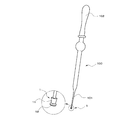
- FIG. 1 The perspective view of the state used for the pipette which shows an example of the attachment for liquid injection which concerns on this invention
- FIG. 1 A diagram showing an example of a micropipette and a pipette tip Sectional drawing of the attachment for liquid injection shown in FIG. Sectional drawing of the use condition explaining the effect
- Sectional drawing of the use condition which shows another example of the attachment for liquid injection which concerns on this invention
- Sectional drawing of the use condition which shows another example of the attachment for liquid injection which concerns on this invention
- Sectional drawing of the use condition which shows another example of the attachment for liquid injection which concerns on this invention
- Sectional drawing of the use condition which shows the state which applied the load to the attachment for liquid injection shown in FIG.
- Sectional drawing of the use condition which shows another example of the attachment for liquid injection which concerns on this invention
- the figure which looked at the attachment for liquid injection shown in Drawing 8 from the tip side (A) is sectional drawing of the use condition explaining the effect
- action and effect of the attachment for liquid injection shown in FIG. (A) is the figure which looked at another example of the stopper part from the front end side of the attachment for liquid injection
- (b) is sectional drawing of the attachment for liquid injection which shows another example of a stopper part
- Sectional drawing of the use condition which shows another example of the attachment for liquid injection which concerns on this invention
- Sectional drawing of the use condition which shows the state which applied the load to the attachment for liquid injection shown in FIG.
- Sectional drawing of the use condition which shows another example of the attachment for liquid injection which concerns on this invention
- the attachment for liquid injection according to the present invention is used when performing a liquid injection operation using a pipette to an introduction port such as a microchannel of a microfluidic chip into which liquid is introduced.
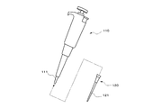
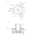
- the pipette is used for sucking and injecting a small amount of liquid in the microliter unit as shown in FIG. 2 in addition to the pipette 100 for sucking and injecting the liquid by the rubber ball 102.
- the attachment for liquid injection according to the present invention is not limited to one that is detachably attached to the tip 101 of the pipette 100 or the tip 111 of the micropipette 110.
- the pipette 100 or the micropipette 110 can be used by being detachably attached to the tip 121 of the pipette tip 120 attached to the tip of the pipette 100 or the micropipette 110.
- the tip portion 101 of the pipette 100 and the tip portion 121 of the pipette tip 120 those which are usually commercially available and made by injection molding using thermoplastic resin as a molding material can be used.
- FIG. 1 a case where a liquid injection attachment is detachably attached to a tip portion 101 of a pipette 100 that sucks and injects liquid with a rubber ball 102 will be described.
- the description can also be applied to a case where the tip 111 of the micropipette 110 and the tip 121 of the pipette tip 120 shown in FIG.
- FIG. 1 is a perspective view of a state in which an example of a liquid injection attachment according to the present invention is attached to the tip of a pipette, and shows an enlarged portion surrounded by a one-dot chain line circle.
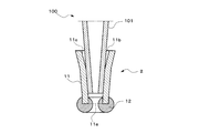
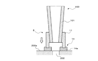
- FIG. 3 is a cross-sectional view of the liquid injection attachment shown in FIG.
- the liquid injection attachment 1 has an attachment main body 11 attached to the tip 101 of the pipette 100 and a gasket 12 held by the attachment main body 11.
- the attachment main body 11 has a cylindrical shape so that it can be detachably attached to the outer periphery of the tip 101 of the pipette 100.
- the tip (lower end in FIG. 3) of the attachment main body 11 is a liquid outlet 11a through which the liquid in the pipette 100 flows out, and the rear end (upper end in FIG. 3) is an insertion port into which the tip 101 of the pipette 100 is inserted. 11b.
- the attachment body 11 can be formed in a cylindrical shape having a constant inner diameter from the liquid outlet 11a to the insertion port 11b.
- the tapered shape gradually decreases in diameter from the insertion port 11b toward the liquid outlet port 11a. It is preferable to have a funnel shape. As shown in FIG. 3, the inner surface of the attachment body 11 is formed in a funnel shape that is inclined at a constant angle in the axial direction.
- the attachment main body 11 is generally formed of a material harder than the gasket 12 in order to maintain a stable mounting state with respect to the tip portion 101 and to hold the gasket 12 stably.
- the specific material is not particularly limited, but is preferably a synthetic resin that is inexpensive and easy to mold.
- the specific synthetic resin is appropriately selected depending on the type of liquid, and examples thereof include thermoplastic resins such as polyethylene and polypropylene.
- the gasket 12 is formed of a rubber-like elastic body.
- the gasket 12 is provided around the liquid outlet 11a so as to surround the liquid outlet 11a of the attachment body 11.
- the gasket 12 is formed by an O-ring having a circular cross section, and further protrudes from the liquid outlet 11a toward the distal end side of the attachment body 11 (the lower side in FIG. 3).
- the gasket 12 is a separate member from the attachment main body 11, it can be formed of a material having a good sealing property specialized in sealing performance. For this reason, compared with the case where the whole attachment is formed with an elastic body like the past, the selection range of the gasket material which can be used becomes wide.
- the rubber-like elastic body forming the gasket 12 can be freely selected depending on the material used for the attachment body 11 and the type of liquid. For example, silicone rubber, fluorine rubber, acrylic rubber, nitrile rubber, butyl rubber, or the like is used. be able to.
- the gasket 12 is integrally formed directly with the attachment main body 11, but a separately molded gasket 12 may be bonded around the liquid outlet 11a.
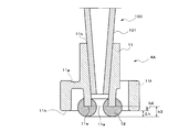
- the operation and effect of the liquid injection attachment 1 are exemplified by the case where the liquid E is injected into the introduction port 202 of the microchannel 201 formed in the microfluidic chip 200. I will explain.
- the liquid injection attachment 1 When injecting the liquid E in the pipette 100 into the microchannel 201 of the microfluidic chip 200, first, the liquid injection attachment 1 is attached to the tip 101 of the pipette 100. Thereafter, the liquid injection attachment 1 is pressed against the upper surface 200 a of the microfluidic chip 200, and the gasket 12 is brought into contact with the periphery of the introduction port 202.
- the gasket 12 is compressed and deformed, and a reaction force due to the compressive deformation is generated in the gasket 12.
- the liquid injection attachment 1 according to the present invention effectively utilizes the reaction force generated by the compressive deformation of the gasket 12 at the time of liquid injection. That is, the reaction force of the gasket 12 opposes the injection pressure at the time of liquid injection. Therefore, the liquid injection attachment 1 exhibits good sealing performance, and the liquid E is introduced into the microchannel 201 from the pipette 100 via the liquid outlet 11a and the inlet 202 without leaking outside.
- the only part that exhibits sealing performance by compressive deformation is the gasket 12 provided at the tip of the attachment body 11.
- the load applied at the time of sealing need only be a small load that compresses and deforms only the gasket 12, and it is not necessary to apply a large load as in the conventional attachment made entirely of elastomer.
- the tip 101 of the pipette 100 is supported from the outer periphery by the cylindrical attachment body 11. Therefore, according to the attachment 1 for liquid injection, the gasket 12 can be easily compressed and deformed with a small load without exerting the risk of deformation or breakage of the tip 101 during liquid injection, and good sealing performance can be exhibited. .
- the liquid injection attachment 1 has a small number of parts and a simple configuration, so that the manufacturing cost is low. Furthermore, since the liquid injection attachment 1 can be disposable, no cleaning work is required. Therefore, there is no liquid contamination.
- the gasket 12 shown in this embodiment is formed by an O-ring, which is a preferable aspect in the present invention.
- the gasket 12 made of an O-ring has a lip 12a having a circular arc cross section at the tip.
- Such a liquid injection attachment 1 can be applied to an automatic pipetting device or a pipetting robot. As a result, the liquid injection operation can be automated. Furthermore, it is also possible to simultaneously inject liquid into a plurality of inlets by attaching each tip of the multichannel pipette.
- FIG. 5 is a sectional view of the usage state showing another example of the liquid injection attachment according to the present invention. Since the parts having the same reference numerals as those of the liquid injection attachment 1 shown in FIGS. 1 to 4 are parts having the same configuration, the description thereof is incorporated here and is omitted here.
- This liquid injection attachment 2 is different from the liquid injection attachment 1 described above in that the inner surface of the attachment main body 11 on the side of the insertion port 11b is formed in a tapered shape with a wider opening toward the outside. Yes.
- the liquid injection attachment 2 has a tapered funnel shape that gradually decreases in diameter from the insertion port 11b toward the liquid outlet port 11a, similar to the liquid injection attachment 1 described above.
- the insertion port 11b is further widened outward.
- the inner surface of the attachment body 11 has a tapered surface 11c that is inclined so that the inclination angle changes in the middle part in the axial direction and further widens toward the outer side from the middle part toward the insertion port 11b. ing.
- the tapered surface 11c does not come into close contact with the outer peripheral surface of the tip 101 when the tip 101 of the pipette 100 is inserted into the insertion port 11b, and increases in the radial direction from the middle of the attachment body 11 toward the insertion port 11b. It is formed to spread gradually.
- the liquid injection attachment 2 has the following effects in addition to the effects exhibited by the liquid injection attachment 1 described above. Since the liquid injection attachment 2 has a wide opening on the insertion port 11b side, even when the center axis of the tip 101 and the center axis of the attachment body 11 are misaligned when attached to the tip 101 of the pipette 100, The tip 101 can be smoothly guided into the insertion port 11b by the tapered surface 11c. Therefore, the effect of improving the workability of mounting to the tip 101 can be obtained.
- Such an effect is particularly remarkable when the liquid injection attachment 2 is applied to an automatic liquid injection system using an automatic pipetting device or a pipetting robot. That is, when fitting the tip of an automatic pipetting device or pipetting robot with an attachment, high positioning accuracy including a linear motion mechanism is required. In some cases, high processing accuracy of the tip and attachment is also required. For this reason, an expensive automatic pipetting device or a pipetting robot may be required.
- FIG. 6 is a sectional view of a usage state showing still another example of the liquid injection attachment according to the present invention. Since the parts having the same reference numerals as those of the liquid injection attachment 1 shown in FIGS. 1 to 4 are parts having the same configuration, the description thereof is incorporated here and is omitted here.
- This liquid injection attachment 3 is different from the liquid injection attachment 1 in the structure for attaching a gasket to the attachment main body 11.
- the liquid injection attachment 3 is provided with a step portion 11 d so as to surround the liquid outlet 11 a of the attachment body 11.
- the step portion 11d is recessed in a circular shape in the axial direction from the distal end surface 11e of the attachment main body 11, and is formed concentrically with the liquid outlet 11a.
- the liquid outlet 11a opens at the bottom surface of the step portion 11d.
- the gasket 13 is formed in an annular shape by a rubber-like elastic body similar to the gasket 12 of the liquid injection attachment 1, and is bonded and fixed in the step portion 11d.
- the gasket 13 protrudes from the distal end surface 11e of the attachment main body 11 in a state where the gasket 13 is housed in the stepped portion 11d as described above.
- the protruding tip of the gasket 13 is formed in an arc shape as shown in FIG. 6, and thus has a lip 13a similar to the gasket 12 made of the O-ring of the liquid injection attachment 1 described above. preferable.
- the liquid injection attachment 3 has the following effects in addition to the effects exhibited by the liquid injection attachment 1 described above.
- the distal end surface 11e of the attachment main body 11 abuts around the introduction port 202, and this distal end surface 11e is a stopper. To play a role. Therefore, according to this liquid injection attachment 3, it is possible to prevent excessive compression deformation of the gasket 13 and maintain stable sealing performance.
- Such an effect is particularly remarkable when applied to an automatic liquid injection system using an automatic pipetting device or a pipetting robot. That is, when the automatic pipetting device or pipetting robot tip is automatically fitted to the liquid injection attachment, the accuracy of positioning control in the height direction of the tip is low or the tip or attachment body 11 is inserted. If the processing accuracy of the opening 11b is low, the insertion height of the tip portion with respect to the insertion opening 11b of the attachment body 11 may vary. At this time, if the load at the time of liquid injection is kept constant, the load applied to the gasket also varies, and the gasket may be excessively compressed.
- the tip surface 11e of the attachment body 11 serves as a stopper to prevent excessive compression, so that stable sealing performance can be achieved. Can be maintained. Further, there is no need to use an expensive automatic pipetting device or pipetting robot capable of controlling the position in the height direction with high accuracy, or to maintain the machining accuracy of the insertion port 11b of the attachment body 11 at a high level.
- the liquid injection attachment 3 has a stable sealing performance by the gasket 13 over a range from the time when the gasket 13 abuts the periphery of the introduction port 202 to the time when the front end surface 11 e abuts the periphery of the introduction port 202. It can be exhibited better.
- the liquid injection attachment 3 has a tapered surface 11 c (FIG. 5) on the inner surface on the insertion port 11 b side of the attachment body 11, with a wider opening toward the outside. Of course, it may be formed.
- FIG. 8 is a cross-sectional view of a usage state showing still another example of the liquid injection attachment according to the present invention
- FIG. 9 is a view of the liquid injection attachment shown in FIG. Since the parts having the same reference numerals as those of the liquid injection attachment 1 shown in FIGS. 1 to 4 are parts having the same configuration, the description thereof is incorporated here and is omitted here.
- the attachment 4A for liquid injection is different from the attachment 1 for liquid injection described above in that the attachment main body 11 has a stopper portion 11f for preventing inclination.
- the attachment body 11 of the attachment 4A for liquid injection is provided with a stopper portion 11f that protrudes from the liquid outlet 11a toward the tip side on the outer peripheral side of the gasket 12.
- the stopper portion 11f shown in the present embodiment is formed in a cylindrical shape, and is formed concentrically with the attachment main body 11 so as to surround the gasket 12 with a certain distance on the outer peripheral side of the gasket 12. .
- the stopper portion 11f is connected to the attachment body 11 by an appropriate number of connecting portions 11g. Further, the distal end surface 11h of the stopper portion 11f is arranged at a position protruding from the distal end surface 11e of the attachment body 11 and the gasket 12 is further distal to the distal end surface 11h of the stopper portion 11f. Protruding.
- the liquid injection attachment 4A in addition to the effects exhibited by the liquid injection attachment 1, the following effects are achieved.
- the pipette 100 and the attachment 4A for liquid injection are in contact with the upper surface 200a of the microfluidic chip 200 as shown in FIG.
- the front end surface 11h of the stopper portion 11f contacts the upper surface 200a on the outer peripheral side of the gasket 12. Accordingly, the stopper portion 11f supports the tilted liquid injection attachment 4A and suppresses excessive tilting further.
- the tilt of the pipette 100 and the liquid injection attachment 4A can be easily corrected with the tip surface 11h of the stopper portion 11f in contact with the upper surface 200a as a fulcrum.
- the gasket 12 is compressed and deformed with respect to the upper surface 200a of the microfluidic chip 200 in a state where the pipette 100 and the liquid injection attachment 4A are always maintained in a preferable posture, so that liquid can be injected. Accordingly, it is possible to further improve the good sealing performance when the liquid is injected.
- the stopper portion 11 f also plays a role of a stopper because the tip surface 11 h abuts around the introduction port 202 as shown in FIG. .
- pouring the excessive compression of the gasket 13 can be prevented and the stable sealing performance can also be maintained.
- Such an effect is particularly remarkable when applied to an automatic liquid injection system using an automatic pipetting device or a pipetting robot. That is, as described in the liquid injection attachment 3, even when an excessive load is applied due to variations in the insertion height of the attachment body 11 with respect to the distal end portion 101, according to this liquid injection attachment 4 A, FIG. ), The front end surface 11h of the stopper portion 11f serves as a stopper. For this reason, excessive compression of the gasket 12 can be prevented and stable sealing performance can be maintained. Further, there is no need to use an expensive automatic pipetting device or pipetting robot capable of controlling the position in the height direction with high accuracy, or to maintain the machining accuracy of the insertion port 11b of the attachment body 11 at a high level.
- the protrusion height of the gasket 12 from the tip surface 11e of the attachment body 11 is h3, and the protrusion height of the stopper portion 11f from the tip surface 11e of the attachment body 11 is set.
- the minimum allowable displacement amount and the maximum allowable displacement amount are the minimum value and the maximum value of the displacement amount that can maintain the sealing performance of the gasket.
- the liquid injection attachment 4A is stable by the gasket 12 over a range from the time when the gasket 12 comes into contact with the periphery of the introduction port 202 to the time when the front end surface 11h of the stopper portion 11f comes into contact with the circumference of the introduction port 202.
- the sealed performance can be exhibited better.
- the stopper portion 11f shown in FIGS. 8 and 9 is formed in a cylindrical shape. According to this, since the pipette 100 and the liquid injection attachment 4A can be easily returned to the vertical direction regardless of the direction of 360 °, this is a preferable mode. However, the stopper portion 11f is partially arranged in at least three locations so as to have a uniform angle around the liquid outlet 11a, for example, as in the liquid injection attachment 4B shown in FIG. It may be a thing.
- the stopper portion 11f is not limited to being integrally formed with the attachment main body 11.
- the stopper portion 11f may be formed separately from the attachment main body 11.
- the stopper portion 11f is preferably detachable from the outer peripheral surface of the attachment main body 11. Since the stopper part 11f can be provided as needed, useless use of the stopper part 11f can be eliminated.
- liquid injection attachments 4A to 4C also have a tapered surface 11c (see FIG. 5) having a wider opening toward the outside on the inner surface of the attachment main body 11 on the insertion port 11b side, as with the liquid injection attachment 2 described above. Of course, 5) may be formed.
- FIG. 12 is a sectional view of the usage state showing still another example of the liquid injection attachment according to the present invention. Since the parts having the same reference numerals as those of the liquid injection attachment 1 shown in FIGS. 1 to 4 are parts having the same configuration, the description thereof is incorporated here and is omitted here.
- the liquid injection attachment 5 is different from the gasket 12 of the liquid injection attachment 1 in the shape of the gasket.
- the gasket 14 of the liquid injection attachment 5 is formed of the same elastic body as the gasket 12 of the liquid injection attachment 1 described above, but is easy when a load is applied to the tip of the gasket body 14a. It is different in that it has a structure integrally provided with a lip 14b that seals by being crushed.
- the gasket main body 14 a is an annular body having a rectangular cross section, and is provided around the liquid outlet 11 a of the attachment main body 11.
- the front end surface 14c of the gasket body 14a is a flat surface.
- the lip 14b is formed of an annular ridge that integrally protrudes from a part of the tip surface 14c of the gasket body 14a.
- the liquid injection attachment 5 has the following effects in addition to the effects exhibited by the liquid injection attachment 1 described above. Since the protruding lip 14 b is provided at the tip of the gasket 14, the lip 14 b comes into contact with the upper surface 200 a around the introduction port 202 when liquid is injected. When a load is applied to the gasket 14, the lip 14 b is easily crushed and seals the periphery of the introduction port 202 as shown in FIG. 13. For this reason, a sealing surface pressure can be raised and sealing performance can be improved more. When viewed from the entirety of the gasket 14, the lip 14 b has a very small volume, and therefore has a small crushing volume. For this reason, the load applied at the time of sealing may be smaller.
- the attachment 5 for liquid injection exhibits particularly excellent effects when applied to an automatic pipetting device or a dispensing device that simultaneously injects liquid using a plurality of pipettes. That is, in the automatic pipetting device and the dispensing device, not only the control accuracy in the height direction of the device, but also the tolerance in the height direction of each of the plurality of pipettes affects the crushing amount of each gasket. In this case, if the accuracy in the height direction of the device or the accuracy in the height direction of each pipette is low, not only will the amount of crushing of each gasket differ, but also the reaction force when pressed against the microfluidic chip will vary. In some cases, the sealing performance varies for each liquid injection attachment.
- the lip 14b protruding at a predetermined height from the gasket body 14a can absorb the variation in the amount of crushing caused by the variation in the height direction of the device and the plurality of pipettes.
- variation in reaction force from the microfluidic chip 200 can be absorbed.
- the lip 14b eliminates variations in the sealing performance for each liquid injection attachment 5 and maintains stable sealing performance. It becomes possible.
- the gasket 14 preferably has h5> h6 when the axial height of the gasket body 14a is h5 and the axial height of the lip 14b is h6. Since the gasket body 14a having a high height (thickness) is disposed at the base of the lip 14b, the fall of the lip 14b can be suppressed. Further, since the volume of the lip 14b is sufficiently smaller than the gasket body 14a, the reaction force when the lip 14b is compressed and deformed is also reduced. For this reason, the lip 14b can exhibit a reliable sealing performance even with a small load.
- the lip 14b shown in FIG. 12 has a triangular cross section
- the specific cross sectional shape of the lip 14b is not particularly limited.
- the specific dimensions of the lip portion 14b are not particularly limited.
- the R (curvature radius) at the tip of the lip 14b can be 0.1 to 0.4 mm, preferably 0.1 to 0.3 mm.
- the angle ⁇ of the tip of the lip 14b can be 0 to 60 °, preferably 15 to 45 °.
- the height h6 of the lip 14b can be 0.05 to 1.0 mm, preferably 0.1 to 0.3 mm.
- gasket 14 of the liquid injection attachment 5 can be used in place of the gaskets 12 and 13 of the liquid injection attachments 2, 3, 4A to 4C.
- FIG. 14 is a sectional view of the usage state showing still another example of the liquid injection attachment according to the present invention. Since the parts having the same reference numerals as those of the liquid injection attachment 1 shown in FIGS. 1 to 4 are parts having the same configuration, the description thereof is incorporated here and is omitted here.
- the attachment 6 for liquid injection shows a structure that can be preferably applied when the diameter of the introduction port 202 of the microfluidic chip 200 is larger than the outer diameter of the tip of the attachment body 11.
- the gasket 15 of the attachment 6 for liquid injection is provided on the outer surface of the distal end portion of the attachment body 11 and seals between the inner peripheral surface (rising side surface) 202a of the introduction port 202. .
- the gasket 15 is provided so as to protrude in the radial direction from the outer peripheral surface of the attachment main body 11 by an elastic body similar to the gasket 12 of the liquid injection attachment 1 described above.
- the outer diameter of the gasket 15 is formed to be slightly larger than the inner diameter of the inner peripheral surface 202a of the inlet port 202.
- the gasket 15 is formed in a circular arc shape in cross section, but may have a trapezoidal cross section, a triangular cross section and the like as long as it protrudes in the radial direction.
- the gasket 15 serves as a lip, and the tip ( The peak value due to the lip tip) stands, and the space between the inner peripheral surface 202a of the introduction port 202 can be satisfactorily sealed.
- liquid injection can be performed by using the liquid injection attachments 2, 3, 4A to 4C, 5 and 6 described above in the same manner.
- a liquid E such as a reagent contained in a sample container C such as a microtube, a sample tube, a vial, a test tube, a Spitz tube, or a conical tube is aspirated and collected by the tip 101 of the pipette 100 (FIG. 15A).
- a sample container C such as a microtube, a sample tube, a vial, a test tube, a Spitz tube, or a conical tube is aspirated and collected by the tip 101 of the pipette 100 (FIG. 15A).
- the liquid injection attachment 1 is not yet attached to the tip 101 of the pipette 100.
- the pipette 100 is pulled up from the sample container C (FIG. 15B).
- the liquid injection attachment 1 is attached to the tip 101 (FIG. 15C).
- the attachment of the liquid injection attachment 1 is completed when the inner peripheral surface of the attachment main body 11 and the outer peripheral surface of the distal end portion 101 are in close contact with each other and further insertion is prevented.
- the distal end surface 101a of the distal end portion 101 is located slightly closer to the insertion port 11b than the gasket 12 of the liquid injection attachment 1. For this reason, there is no possibility that the tip 101 collides with the gasket 12 and the gasket 12 is detached from the attachment body 11.
- the pipette 100 is pressed toward the introduction 202 for introducing the liquid into the microchannel 201 of the microfluidic chip 200. That is, the gasket 12 of the liquid injection attachment 1 attached to the tip 101 of the pipette 100 is brought into contact with the periphery of the introduction port 202 provided on the upper surface 200a of the microfluidic chip 200 (FIG. 15 (d)). Since the gasket 12 is formed to have a diameter larger than the diameter of the introduction port 202, the gasket 12 is in contact with the upper surface 200 a of the microfluidic chip 200 so as to surround the opening peripheral edge of the introduction port 202. Seal.
- the liquid E in the pipette 100 is injected into the microchannel 201 of the microfluidic chip 200 by the injection pressure of the pipette 100.
- the gasket 12 of the liquid injection attachment 1 is compressed and deformed, and a reaction force is generated.
- the liquid E is introduced into the microchannel 201 from the pipette 100 through the liquid outlet 11a and the inlet 202 of the liquid injection attachment 1 without leaking outside.
- the pipette 100 or the tip 101 can be deformed or damaged only by being attached to the tip 101 of the pipette 100.
- the seal performance by the gasket 12 can be suppressed without fear and liquid leakage can be suppressed by the sealing action of the gasket 12, and the liquid injection operation can be easily performed.
- a commercially available product without a gasket can be used as it is.
- the liquid injection attachment 1 is not yet attached to the tip portion 101 of the pipette 100, so that the liquid injection attachment 1 and the gasket 12 held by the liquid injection attachment 1 are provided. Is not immersed in the liquid E in the sample container C. For this reason, the liquid dripping accompanying immersion does not occur.
- this liquid injection method can use an automatic pipetting device or a pipetting robot to fit the tip 101 of the pipette 100 and the liquid injection attachment 1 or press the pipette 100 against the microfluidic chip 200.
- the liquid can be injected with a simple system configuration.
- the injection can be automated.
- a multi-channel pipette it is possible to inject a liquid into a plurality of microfluidic chips 200 simultaneously.
- Liquid injection attachment 11 Attachment main body 11a: Liquid outlet 11b: Insertion port 11c: Tapered surface 11d: Stepped portion 11e: Tip surface 11f: Stopper portion 11g: Connection Portion 11h: Tip surface 12-15: Gasket 12a, 13a: Lip 14a: Gasket body 14b: Lip 14c: Tip surface 100: Pipette 101: Tip portion 101a: Tip surface 110: Micropipette 120: Pipette tip 121: Tip portion 200 : Microfluidic chip 200a: Upper surface 201: Microchannel 202: Inlet C: Sample container E: Liquid such as reagent
Landscapes
- Health & Medical Sciences (AREA)
- Chemical & Material Sciences (AREA)
- Clinical Laboratory Science (AREA)
- Chemical Kinetics & Catalysis (AREA)
- Analytical Chemistry (AREA)
- Life Sciences & Earth Sciences (AREA)
- Physics & Mathematics (AREA)
- Biochemistry (AREA)
- General Health & Medical Sciences (AREA)
- General Physics & Mathematics (AREA)
- Immunology (AREA)
- Pathology (AREA)
- Sampling And Sample Adjustment (AREA)
- Devices For Use In Laboratory Experiments (AREA)
- Feeding, Discharge, Calcimining, Fusing, And Gas-Generation Devices (AREA)
Abstract
Description
先端に液体流出口を有し、後端に前記ピペット又は前記ピペットチップの先端部が挿入される挿入口を有する筒状のアタッチメント本体と、
前記アタッチメント本体の前記液体流出口の周りに設けられたゴム状弾性体からなるガスケットとを備えることを特徴とする液体注入用アタッチメント。
前記ピペット又は前記ピペットチップの先端部に、請求項1~12の何れかに記載の液体注入用アタッチメントを装着する工程と、
前記液体注入用アタッチメントを装着した前記ピペット又は前記ピペットチップを液体が導入される導入口に向けて押し付ける工程と、
前記ピペットから供給される圧縮気体により、前記液体を前記ピペット又は前記ピペットチップから前記導入口へ注入する工程とを順次実施し、
前記ピペット又は前記ピペットチップを前記導入口に向けて押し付けたときに前記ガスケットを圧縮変形させることにより、液体注入圧に対抗し得る反力を前記ガスケットに発生させ、前記ピペット又は前記ピペットチップから前記導入口へ注入する液体をシールすることを特徴とする液体注入方法。
11:アタッチメント本体
11a:液体流出口
11b:挿入口
11c:テーパー面
11d:段部
11e:先端面
11f:ストッパー部
11g:連結部
11h:先端面
12~15:ガスケット
12a、13a:リップ
14a:ガスケット本体
14b:リップ
14c:先端面
100:ピペット
101:先端部
101a:先端面
110:マイクロピペット
120:ピペットチップ
121:先端部
200:マイクロ流体チップ
200a:上面
201:マイクロチャネル
202:導入口
C:サンプル容器
E:試薬等の液体
Claims (13)
- 液体が導入される導入口へ注入するピペット、又は該ピペットに取り付けられるピペットチップに、着脱可能に装着される液体注入用アタッチメントであって、
先端に液体流出口を有し、後端に前記ピペット又は前記ピペットチップの先端部が挿入される挿入口を有する筒状のアタッチメント本体と、
前記アタッチメント本体の前記液体流出口の周りに設けられたゴム状弾性体からなるガスケットとを備えることを特徴とする液体注入用アタッチメント。 - 前記アタッチメント本体は合成樹脂からなることを特徴とする請求項1記載の液体注入用アタッチメント。
- 前記アタッチメント本体の前記挿入口側の内面は、軸方向の中途部から前記挿入口に向かうに従って外側に向けて間口が広がるように傾斜するテーパー面を有していることを特徴とする請求項1又は2記載の液体注入用アタッチメント。
- 前記アタッチメント本体の先端面に、前記液体流出口を取り囲むように凹んだ段部が設けられていると共に、該段部内に、前記ガスケットが前記アタッチメント本体の先端面から突出するように設けられていることを特徴とする請求項1、2又は3記載の液体注入用アタッチメント。
- 前記ガスケットの軸方向の高さをh1、前記段部の軸方向の深さをh2としたとき、h1>h2であり、且つ、h1とh2の差分Δhは、前記ガスケットの最小許容変位量と最大許容変位量の間に設定されていることを特徴とする請求項4記載の液体注入用アタッチメント。
- 前記アタッチメント本体の前記ガスケットの外周側に、前記液体流出口よりも先端側に突出するストッパー部を有すると共に、前記ガスケットは、前記ストッパー部の先端面よりも先端側に突出していることを特徴とする請求項1、2又は3記載の液体注入用アタッチメント。
- 前記ガスケットの前記アタッチメント本体先端面からの突出高さをh3、前記ストッパー部の前記アタッチメント本体先端面からの突出高さをh4としたとき、h3>h4であり、且つ、h3とh4の差分Δhは、前記ガスケットの最小許容変位量と最大許容変位量の間に設定されていることを特徴とする請求項6記載の液体注入用アタッチメント。
- 前記ストッパー部は、前記液体流出口を取り囲むように円筒状に形成されていることを特徴とする請求項6又は7記載の液体注入用アタッチメント。
- 前記ストッパー部は、前記液体流出口の周囲の少なくとも3箇所に分かれて部分的に形成されていることを特徴とする請求項6又は7記載の液体注入用アタッチメント。
- 前記ガスケットは、前記アタッチメント本体の前記液体流出口の周りに設けられたガスケット本体の先端に、前記導入口の周囲に当接した際に潰れることによってシールするリップを備えていることを特徴とする請求項1~9の何れかに記載の液体注入用アタッチメント。
- 前記ガスケット本体の軸方向の高さをh5、前記リップの軸方向の高さをh6としたとき、h5>h6であることを特徴とする請求項10記載の液体注入用アタッチメント。
- 前記ガスケットは、前記アタッチメント本体の外側面に設けられ、前記導入口の内周面との間をシールすることを特徴とする請求項1、2又は3記載の液体注入用アタッチメント。
- サンプル容器に入った液体をピペット又は該ピペットに取り付けたピペットチップにより吸引・採取する工程と、
前記ピペット又は前記ピペットチップの先端部に、請求項1~12の何れかに記載の液体注入用アタッチメントを装着する工程と、
前記液体注入用アタッチメントを装着した前記ピペット又は前記ピペットチップを液体が導入される導入口に向けて押し付ける工程と、
前記ピペットから供給される圧縮気体により、前記液体を前記ピペット又は前記ピペットチップから前記導入口へ注入する工程とを順次実施し、
前記ピペット又は前記ピペットチップを前記導入口に向けて押し付けたときに前記ガスケットを圧縮変形させることにより、液体注入圧に対抗し得る反力を前記ガスケットに発生させ、前記ピペット又は前記ピペットチップから前記導入口へ注入する液体をシールすることを特徴とする液体注入方法。
Priority Applications (3)
| Application Number | Priority Date | Filing Date | Title |
|---|---|---|---|
| US15/112,340 US20160332157A1 (en) | 2014-04-08 | 2015-04-08 | Attachment for liquid injection and liquid injection method |
| JP2015542096A JP6549037B2 (ja) | 2014-04-08 | 2015-04-08 | 液体注入用アタッチメント及び液体注入方法 |
| EP15776545.4A EP2982440B1 (en) | 2014-04-08 | 2015-04-08 | Attachment for liquid injection and liquid injection method |
Applications Claiming Priority (2)
| Application Number | Priority Date | Filing Date | Title |
|---|---|---|---|
| JP2014079268 | 2014-04-08 | ||
| JP2014-079268 | 2014-04-08 |
Publications (1)
| Publication Number | Publication Date |
|---|---|
| WO2015156331A1 true WO2015156331A1 (ja) | 2015-10-15 |
Family
ID=54287904
Family Applications (1)
| Application Number | Title | Priority Date | Filing Date |
|---|---|---|---|
| PCT/JP2015/061016 WO2015156331A1 (ja) | 2014-04-08 | 2015-04-08 | 液体注入用アタッチメント及び液体注入方法 |
Country Status (4)
| Country | Link |
|---|---|
| US (1) | US20160332157A1 (ja) |
| EP (1) | EP2982440B1 (ja) |
| JP (1) | JP6549037B2 (ja) |
| WO (1) | WO2015156331A1 (ja) |
Cited By (3)
| Publication number | Priority date | Publication date | Assignee | Title |
|---|---|---|---|---|
| WO2017199852A1 (ja) * | 2016-05-20 | 2017-11-23 | Nok株式会社 | 液体注入用アタッチメント及び液体注入装置 |
| WO2017208772A1 (ja) * | 2016-05-30 | 2017-12-07 | Nok株式会社 | 液体注入用アタッチメント |
| WO2018043119A1 (ja) * | 2016-08-31 | 2018-03-08 | Nok株式会社 | 液体注入用アタッチメント |
Families Citing this family (3)
| Publication number | Priority date | Publication date | Assignee | Title |
|---|---|---|---|---|
| DE102017117789A1 (de) * | 2017-08-04 | 2019-02-07 | Als Automated Lab Solutions Gmbh | Adapter zur Aufnahme einer Kapillare und dessen Verwendung |
| JP7066130B2 (ja) * | 2018-02-14 | 2022-05-13 | 日本光電工業株式会社 | 無菌サンプリング装置、及びそれを用いたサンプリング方法 |
| SE543488C2 (en) * | 2018-07-02 | 2021-03-09 | Joensson Haakan | A liquid media handling system and a connecting receptable adapted for use in said system |
Citations (5)
| Publication number | Priority date | Publication date | Assignee | Title |
|---|---|---|---|---|
| JPH02503883A (ja) * | 1988-04-18 | 1990-11-15 | イー・ピー・アール・ラブオートメーション・アー・ゲー | ピペット装置 |
| JP2003098150A (ja) * | 2001-07-18 | 2003-04-03 | Pohang Univ Of Science & Technology | 質量分析機のための試料クリーンアップ装置 |
| JP2006322850A (ja) * | 2005-05-19 | 2006-11-30 | Fujifilm Holdings Corp | 送液システム及びその送液方法並びに流路ユニット。 |
| JP2008232951A (ja) * | 2007-03-22 | 2008-10-02 | Fujifilm Corp | 流路部材、ピペットチップ及び液体供給装置 |
| JP2012147751A (ja) * | 2011-01-21 | 2012-08-09 | Hitachi High-Technologies Corp | 分注チップ及び核酸分析装置 |
Family Cites Families (2)
| Publication number | Priority date | Publication date | Assignee | Title |
|---|---|---|---|---|
| DE19742163C2 (de) * | 1997-09-24 | 2001-12-13 | Steffen Hering | Vorrichtung und Verfahren zur Behandlung von Objekten in einem Flüssigkeitsbad |
| AU2003900329A0 (en) * | 2003-01-24 | 2003-02-13 | Microtechnology Centre Management Limited | Microfluidic connector |
-
2015
- 2015-04-08 EP EP15776545.4A patent/EP2982440B1/en not_active Not-in-force
- 2015-04-08 US US15/112,340 patent/US20160332157A1/en not_active Abandoned
- 2015-04-08 WO PCT/JP2015/061016 patent/WO2015156331A1/ja active Application Filing
- 2015-04-08 JP JP2015542096A patent/JP6549037B2/ja active Active
Patent Citations (5)
| Publication number | Priority date | Publication date | Assignee | Title |
|---|---|---|---|---|
| JPH02503883A (ja) * | 1988-04-18 | 1990-11-15 | イー・ピー・アール・ラブオートメーション・アー・ゲー | ピペット装置 |
| JP2003098150A (ja) * | 2001-07-18 | 2003-04-03 | Pohang Univ Of Science & Technology | 質量分析機のための試料クリーンアップ装置 |
| JP2006322850A (ja) * | 2005-05-19 | 2006-11-30 | Fujifilm Holdings Corp | 送液システム及びその送液方法並びに流路ユニット。 |
| JP2008232951A (ja) * | 2007-03-22 | 2008-10-02 | Fujifilm Corp | 流路部材、ピペットチップ及び液体供給装置 |
| JP2012147751A (ja) * | 2011-01-21 | 2012-08-09 | Hitachi High-Technologies Corp | 分注チップ及び核酸分析装置 |
Non-Patent Citations (1)
| Title |
|---|
| See also references of EP2982440A4 * |
Cited By (3)
| Publication number | Priority date | Publication date | Assignee | Title |
|---|---|---|---|---|
| WO2017199852A1 (ja) * | 2016-05-20 | 2017-11-23 | Nok株式会社 | 液体注入用アタッチメント及び液体注入装置 |
| WO2017208772A1 (ja) * | 2016-05-30 | 2017-12-07 | Nok株式会社 | 液体注入用アタッチメント |
| WO2018043119A1 (ja) * | 2016-08-31 | 2018-03-08 | Nok株式会社 | 液体注入用アタッチメント |
Also Published As
| Publication number | Publication date |
|---|---|
| EP2982440B1 (en) | 2019-03-27 |
| US20160332157A1 (en) | 2016-11-17 |
| JP6549037B2 (ja) | 2019-07-24 |
| EP2982440A1 (en) | 2016-02-10 |
| EP2982440A4 (en) | 2017-01-04 |
| JPWO2015156331A1 (ja) | 2017-04-13 |
Similar Documents
| Publication | Publication Date | Title |
|---|---|---|
| WO2015156331A1 (ja) | 液体注入用アタッチメント及び液体注入方法 | |
| US10213783B2 (en) | Nucleic acid extracting device | |
| JP2015199028A (ja) | マイクロチャネルへの液体注入方法 | |
| WO2017208772A1 (ja) | 液体注入用アタッチメント | |
| US9987630B2 (en) | Fluid handling device and method of using the same | |
| US11426725B2 (en) | Flow cell having a reagent reservoir | |
| EP3460485B1 (en) | Fluid handling device | |
| WO2018043119A1 (ja) | 液体注入用アタッチメント | |
| WO2018061072A1 (ja) | ピペットチップ装着用アダプタ | |
| US20190275526A1 (en) | Liquid injection attachment and liquid injection device | |
| US20180272332A1 (en) | Attachment structure for pipette or pipette tip and attachment for liquid injection, and attachment for liquid injection | |
| US20130206268A1 (en) | Connecting device for the fluidic contacting of microfluidic chips | |
| US20220008915A1 (en) | Specimen container and cap | |
| JP5395480B2 (ja) | マイクロチップ及びマイクロチップセット | |
| JP2009281954A (ja) | 反応容器プレート及び反応処理方法 | |
| CN113677436A (zh) | 试样容器及帽 | |
| WO2024004380A1 (ja) | コネクタ、及びマイクロ流体デバイスの接続構造 | |
| JP2023150202A (ja) | インターフェースおよび流体取扱デバイス | |
| JP7036126B2 (ja) | 流体デバイスおよび流路供給システム | |
| EP3293524B1 (en) | Fluidic coupling | |
| CN117813511A (zh) | 隔板 | |
| CN117320811A (zh) | 注射式插塞和用于分析测定的包括这种注射式插塞的盒 | |
| WO2019073955A1 (ja) | ピストン及びシリンジ |
Legal Events
| Date | Code | Title | Description |
|---|---|---|---|
| ENP | Entry into the national phase |
Ref document number: 2015542096 Country of ref document: JP Kind code of ref document: A |
|
| WWE | Wipo information: entry into national phase |
Ref document number: 2015776545 Country of ref document: EP |
|
| 121 | Ep: the epo has been informed by wipo that ep was designated in this application |
Ref document number: 15776545 Country of ref document: EP Kind code of ref document: A1 |
|
| WWE | Wipo information: entry into national phase |
Ref document number: 15112340 Country of ref document: US |
|
| NENP | Non-entry into the national phase |
Ref country code: DE |