WO2015151795A1 - Optical film, polarizing plate, method for producing polarizing plate, image display device and method for manufacturing image display device - Google Patents
Optical film, polarizing plate, method for producing polarizing plate, image display device and method for manufacturing image display device Download PDFInfo
- Publication number
- WO2015151795A1 WO2015151795A1 PCT/JP2015/057845 JP2015057845W WO2015151795A1 WO 2015151795 A1 WO2015151795 A1 WO 2015151795A1 JP 2015057845 W JP2015057845 W JP 2015057845W WO 2015151795 A1 WO2015151795 A1 WO 2015151795A1
- Authority
- WO
- WIPO (PCT)
- Prior art keywords
- film
- optical film
- hard coat
- coat layer
- acid
- Prior art date
Links
- YSWFXKKDKNCPPW-UHFFFAOYSA-N CC(COC(c(cc1)cc(cc2)c1cc2C(OCC(C)OC(c(ccc1c2)cc1ccc2C(OCC(C)OC(c1cc(cc(cc2)C(OCC(C)O)=O)c2cc1)=O)=O)=O)=O)=O)O Chemical compound CC(COC(c(cc1)cc(cc2)c1cc2C(OCC(C)OC(c(ccc1c2)cc1ccc2C(OCC(C)OC(c1cc(cc(cc2)C(OCC(C)O)=O)c2cc1)=O)=O)=O)=O)=O)O YSWFXKKDKNCPPW-UHFFFAOYSA-N 0.000 description 2
- SGBYRRAMVXCDBS-UHFFFAOYSA-N CC(COC(c(cc1)ccc1-c(cc1)ccc1C(OCC(C)O)=O)=O)O Chemical compound CC(COC(c(cc1)ccc1-c(cc1)ccc1C(OCC(C)O)=O)=O)O SGBYRRAMVXCDBS-UHFFFAOYSA-N 0.000 description 2
- JLWGDDMGHDXVCL-UHFFFAOYSA-N CC(COC(c(ccc1c2)cc1ccc2C(OC(C)CO)=O)=O)O Chemical compound CC(COC(c(ccc1c2)cc1ccc2C(OC(C)CO)=O)=O)O JLWGDDMGHDXVCL-UHFFFAOYSA-N 0.000 description 2
Images


Classifications
-
- G—PHYSICS
- G02—OPTICS
- G02B—OPTICAL ELEMENTS, SYSTEMS OR APPARATUS
- G02B1/00—Optical elements characterised by the material of which they are made; Optical coatings for optical elements
- G02B1/10—Optical coatings produced by application to, or surface treatment of, optical elements
- G02B1/14—Protective coatings, e.g. hard coatings
-
- C—CHEMISTRY; METALLURGY
- C08—ORGANIC MACROMOLECULAR COMPOUNDS; THEIR PREPARATION OR CHEMICAL WORKING-UP; COMPOSITIONS BASED THEREON
- C08F—MACROMOLECULAR COMPOUNDS OBTAINED BY REACTIONS ONLY INVOLVING CARBON-TO-CARBON UNSATURATED BONDS
- C08F232/00—Copolymers of cyclic compounds containing no unsaturated aliphatic radicals in a side chain, and having one or more carbon-to-carbon double bonds in a carbocyclic ring system
- C08F232/08—Copolymers of cyclic compounds containing no unsaturated aliphatic radicals in a side chain, and having one or more carbon-to-carbon double bonds in a carbocyclic ring system having condensed rings
-
- C—CHEMISTRY; METALLURGY
- C08—ORGANIC MACROMOLECULAR COMPOUNDS; THEIR PREPARATION OR CHEMICAL WORKING-UP; COMPOSITIONS BASED THEREON
- C08F—MACROMOLECULAR COMPOUNDS OBTAINED BY REACTIONS ONLY INVOLVING CARBON-TO-CARBON UNSATURATED BONDS
- C08F32/00—Homopolymers and copolymers of cyclic compounds having no unsaturated aliphatic radicals in a side chain, and having one or more carbon-to-carbon double bonds in a carbocyclic ring system
- C08F32/08—Homopolymers and copolymers of cyclic compounds having no unsaturated aliphatic radicals in a side chain, and having one or more carbon-to-carbon double bonds in a carbocyclic ring system having two condensed rings
-
- G—PHYSICS
- G02—OPTICS
- G02B—OPTICAL ELEMENTS, SYSTEMS OR APPARATUS
- G02B5/00—Optical elements other than lenses
- G02B5/30—Polarising elements
- G02B5/3025—Polarisers, i.e. arrangements capable of producing a definite output polarisation state from an unpolarised input state
- G02B5/3033—Polarisers, i.e. arrangements capable of producing a definite output polarisation state from an unpolarised input state in the form of a thin sheet or foil, e.g. Polaroid
-
- G—PHYSICS
- G02—OPTICS
- G02F—OPTICAL DEVICES OR ARRANGEMENTS FOR THE CONTROL OF LIGHT BY MODIFICATION OF THE OPTICAL PROPERTIES OF THE MEDIA OF THE ELEMENTS INVOLVED THEREIN; NON-LINEAR OPTICS; FREQUENCY-CHANGING OF LIGHT; OPTICAL LOGIC ELEMENTS; OPTICAL ANALOGUE/DIGITAL CONVERTERS
- G02F1/00—Devices or arrangements for the control of the intensity, colour, phase, polarisation or direction of light arriving from an independent light source, e.g. switching, gating or modulating; Non-linear optics
- G02F1/01—Devices or arrangements for the control of the intensity, colour, phase, polarisation or direction of light arriving from an independent light source, e.g. switching, gating or modulating; Non-linear optics for the control of the intensity, phase, polarisation or colour
- G02F1/13—Devices or arrangements for the control of the intensity, colour, phase, polarisation or direction of light arriving from an independent light source, e.g. switching, gating or modulating; Non-linear optics for the control of the intensity, phase, polarisation or colour based on liquid crystals, e.g. single liquid crystal display cells
- G02F1/133—Constructional arrangements; Operation of liquid crystal cells; Circuit arrangements
- G02F1/1333—Constructional arrangements; Manufacturing methods
- G02F1/1335—Structural association of cells with optical devices, e.g. polarisers or reflectors
- G02F1/133528—Polarisers
-
- G—PHYSICS
- G02—OPTICS
- G02F—OPTICAL DEVICES OR ARRANGEMENTS FOR THE CONTROL OF LIGHT BY MODIFICATION OF THE OPTICAL PROPERTIES OF THE MEDIA OF THE ELEMENTS INVOLVED THEREIN; NON-LINEAR OPTICS; FREQUENCY-CHANGING OF LIGHT; OPTICAL LOGIC ELEMENTS; OPTICAL ANALOGUE/DIGITAL CONVERTERS
- G02F2201/00—Constructional arrangements not provided for in groups G02F1/00 - G02F7/00
- G02F2201/50—Protective arrangements
Definitions
- the present invention relates to an optical film having a hard coat layer on at least one surface of a film substrate, a polarizing plate having the optical film and a manufacturing method thereof, an image display device having the polarizing plate, and a manufacturing method thereof. It is.
- a polarizing plate used in an image display device such as a liquid crystal display device (LCD).
- LCD liquid crystal display device
- a hard coat layer that is cured by irradiation with active energy rays on a film substrate such as a cellulose ester film and arrange it as a polarizing plate protective film.
- the cellulose ester film may contain a specific organic acid, a specific phenol compound, or a specific polymer containing a benzene ring in the main chain. It is known to add (for example, refer to Patent Document 2).
- a transparent protective part made of glass or plastic is provided from the viewpoint of improving mechanical strength and designability.
- a gap layer exists between the polarizing plate protective film on the surface of the liquid crystal display panel and the protective part, light reflection or reflection at the interface between the liquid crystal display panel and the gap layer or between the protective part and the gap layer may occur.
- the contrast and brightness decrease due to scattering.
- a technique for avoiding the above inconvenience by filling the gap layer with a filler such as a photocurable resin for example, see Patent Document 3).
- a film base material with a hindered amine compound, a specific organic acid, a specific phenol compound, or a specific polymer containing a benzene ring in the main chain hereinafter these are collectively referred to as a compound or the like.
- a compound or the like Is added to the hard coat layer of the polarizing plate protective film, and a specific system in which a protective part is provided via the filling layer, a compound or the like diffuses from the film substrate to the filling layer, and a radical of the compound or the like.
- a new problem has been discovered in which unevenness of curing of the resin occurs in the filling layer due to the trapping action, thereby causing poor adhesion between the protective portion and the filling layer, and in turn causing poor display (display unevenness).
- the present invention has been made in order to solve the above-described problems, and the object thereof is to provide a non-uniform curing of the filling layer and a display thereby when a protective part is provided on the hard coat layer via the filling layer.
- the optical film capable of suppressing the diffusion of the compound contained in the film substrate to the hard coat layer surface, the polarizing plate having the optical film, the production method thereof, and the polarizing plate are provided.
- An object of the present invention is to provide an image display device and a manufacturing method thereof.
- An optical film according to one aspect of the present invention is an optical film having a hard coat layer on at least one surface of a film substrate,
- the film substrate includes a hindered amine compound, a polymer containing a repeating unit derived from a monomer represented by the following general formula (P), an organic acid represented by the following general formula (Q), and the following general formula (S). Containing at least one of the compounds represented by:
- the hard coat layer has a surface free energy of 30 mN / m or more after alkali treatment.
- R 1 represents a hydrogen atom or an aliphatic group having 1 to 4 carbon atoms.
- R 2 represents a substituent.
- (A) is necessary for forming a 5- or 6-membered ring.
- R 26 represents an aryl group
- R 27 and R 28 each independently represents a hydrogen atom, an alkyl group, or an aryl group.
- R 1 represents a hydrogen atom or a substituent
- R 2 represents a substituent represented by the following general formula (a).
- N1 represents an integer of 0 to 4, and n1 is 2
- a plurality of R 1 may be the same or different from each other
- n2 represents an integer of 1 to 5
- a plurality of R 2 may be the same or different from each other May be.
- A represents a substituted or unsubstituted aromatic ring
- R 3 and R 4 are each independently a hydrogen atom, an alkyl group having 1 to 5 carbon atoms, or the following general formula (b
- R 5 represents a single bond or an alkylene group having 1 to 5 carbon atoms
- X represents a substituted or unsubstituted aromatic ring
- n3 represents an integer of 0 to 10
- the plurality of R 5 and X may be the same or different.
- X represents a substituted or unsubstituted aromatic ring
- R 6 , R 7 , R 8 , and R 9 are each independently a hydrogen atom or an alkyl having 1 to 5 carbon atoms.
- N5 represents an integer of 1 to 11, and when n5 is 2 or more, a plurality of R 6 , R 7 , R 8 and X may be the same or different. It is.
- the hard coat layer of the optical film is hydrophilized with a surface free energy of 30 mN / m or more, the hindered amine compound contained in the film base material diffuses to the hard coat layer side in this hydrophilized state. Even so, the compound and the like can be trapped in the hydrophilic portion of the hard coat layer. That is, diffusion of the compound or the like to the hard coat layer surface can be suppressed.
- FIG. 1 is a cross-sectional view illustrating a schematic configuration of an image display device according to an embodiment of the present invention. It is a top view which shows typically the structure of the outline of the manufacturing apparatus of the diagonally stretched film used by the said embodiment. It is a top view which shows typically an example of the rail pattern of the extending
- the inventors of the present application have studied various methods for improving the curing unevenness of the filled layer when an optical film (polarizing plate protective film) containing a hindered amine compound or the like is used.
- the hard coat layer on the polarizer protective film is hydrophilized so that the surface free energy is 30 mN / m or more, so that the compound diffused from the film substrate is trapped in the hard coat layer, and then filled into the filling layer. It was found that preventing the spread of Thereby, it is possible to provide a filling layer on the polarizing plate protective film without causing uneven curing, poor adhesion between the protective part and the filling layer, and poor appearance or display failure of the image display device due to uneven curing. Etc. could be prevented.
- the image display apparatus of this embodiment will be described.
- FIG. 1 is a cross-sectional view illustrating a schematic configuration of an image display device 1 according to the present embodiment.
- the image display device 1 is configured by attaching a protective part 3 to a polarizing plate 5 (particularly on an optical film 15 described later) of the liquid crystal display panel 2 via a filling layer 31.
- the filling layer 31 is an adhesive layer (void filler) made of a photocurable resin such as acrylic, and is formed on the entire surface of the polarizing plate 5 of the liquid crystal display panel 2.
- the protection unit 3 protects the surface of the liquid crystal display panel 2 and is formed of a front plate made of acrylic resin or glass, for example.
- a touch panel (such as a capacitance method or a resistance film method) may be used as the protection unit 3 instead of the front plate.
- the liquid crystal display panel 2 is configured by disposing polarizing plates 5 and 6 on both sides of a liquid crystal cell 4 (display cell) in which a liquid crystal layer is sandwiched between a pair of substrates.
- the polarizing plate 5 is attached to one surface side (for example, the viewing side) of the liquid crystal cell 4 via the adhesive layer 7.
- the polarizing plate 6 is attached to the other surface side (for example, the backlight 9 side) of the liquid crystal cell 4 through the adhesive layer 8.
- the driving method of the liquid crystal display panel 2 is not particularly limited, and various driving methods such as an IPS (In Plane Switching) type and a TN (Twisted Nematic) method can be employed.
- the polarizing plate 5 includes a polarizer 11 that transmits predetermined linearly polarized light, a film base 12 and a hard coat layer 13 that are sequentially laminated on the protective portion 3 side of the polarizer 11, and a liquid crystal cell 4 side of the polarizer 11. It is comprised with the optical film 14 laminated
- the film base 12 and the hard coat layer 13 constitute an optical film 15 as a protective film formed on the surface on the viewing side of the polarizer 11.
- the film substrate 12 is made of, for example, a cellulose ester film, but is not limited to this cellulose ester film.
- the optical film 14 is provided to protect the back surface of the polarizing plate 5.
- the optical film 14 may be made of the same material as the film substrate 12 (for example, cellulose ester) or may be made of other materials.
- the film substrate 12 may be composed of a ⁇ / 4 film.
- the ⁇ / 4 film is a layer that imparts an in-plane retardation of about 1 ⁇ 4 of the wavelength to transmitted light, and in the present embodiment, the ⁇ / 4 film is composed of a film that has been subjected to oblique stretching described later.
- the angle (crossing angle) formed between the slow axis of the ⁇ / 4 film and the absorption axis of the polarizer 11 is 30 ° to 60 °, whereby the linearly polarized light from the polarizer 11 is converted into the ⁇ / 4 film ( It is converted into circularly polarized light or elliptically polarized light by the film substrate 12).
- the polarizing plate can be used regardless of how the transmission axis of the polarizer 11 (perpendicular to the absorption axis) and the transmission axis of the polarized sunglasses are misaligned.
- the light component parallel to the transmission axis of the polarized sunglasses contained in the light emitted from 5 (circularly polarized light or elliptically polarized light) can be guided to the eyes of the observer. Thereby, it can suppress that it becomes difficult to see a display image with the angle to observe.
- the film substrate 12 may contain a hindered amine compound.
- the optical film 15 in which the hard coat layer 13 is formed on the film substrate 12 is bonded (UV bonded) to the polarizer 11 by, for example, ultraviolet irradiation. By this UV irradiation, the film substrate 12 and the hard coat layer are bonded. 13 (light-resistant adhesion) may deteriorate. However, when the film base 12 contains a hindered amine compound, the above light-resistant adhesion can be improved.
- the film substrate 12 includes a specific organic acid, a specific phenol compound, or a specific polymer containing a benzene ring in the main chain. May be contained.
- the polarizing plate 6 includes a polarizer 21 that transmits predetermined linearly polarized light, an optical film 22 that is disposed on the liquid crystal cell 4 side of the polarizer 21, and an optical that is disposed on the opposite side of the polarizer 21 from the liquid crystal cell 4.
- the film 23 is laminated.
- the polarizer 21 is disposed so that the transmission axis is perpendicular to the polarizer 11 (crossed Nicol state).
- the optical films 22 and 23 are provided to protect the front and back surfaces of the polarizing plate 6, but they may be made of the same material (for example, cellulose ester) as the film substrate 12 of the polarizing plate 5. However, it may be composed of other materials.
- the above-described optical film 15 can be used for purposes other than the polarizing plate.
- the hard coat layer 13 may be provided on both surfaces of the film substrate 12. Therefore, in the optical film 15, it can be said that the hard coat layer 13 may be formed on at least one surface of the film substrate 12.
- the hard coat layer 13 of the optical film 15 is a layer having a surface free energy of 30 mN / m or more.
- the surface free energy of the hard coat layer 13 is a polar component a (mN / m), a hydrogen bond component b (mN / m), and a dispersion component c (mN / m) of the surface free energy of the hard coat layer 13. Refers to the sum of In addition, the calculation method of these components is mentioned later.
- the hard coat layer 13 is hydrophilized with a surface free energy of 30 mN / m or more. In this hydrophilized state, even if a hindered amine compound or the like contained in the film substrate 12 is diffused to the hard coat layer 13 side, the compound or the like can be trapped in the hydrophilized portion of the hard coat layer 13. it can. That is, the diffusion of the compound or the like to the hard coat layer 13 surface can be suppressed.
- the diffusion of the compound or the like in the film substrate 12 to the filling layer 31 is suppressed.
- production of the nonuniformity of hardening can be suppressed in the filling layer 31, and the adhesion failure of the protection part 3 and the filling layer 31 by this hardening nonuniformity can be suppressed.
- the surface free energy of the hard coat layer 13 is 40 mN / m or more from the viewpoint of easily obtaining the target effect of the present embodiment.
- the hard coat layer 13 is preferably subjected to an alkali treatment under the following alkaline conditions.
- Alkali treatment conditions Alkaline solution: 2 mol / L sodium hydroxide solution Treatment temperature: 50 ° C Processing time: 120 seconds
- the surface free energy of the hard coat layer 13 can be increased by increasing the content of fine particles, which will be described later. However, if the fine particles are contained to exceed 100 mN / m, the transparency and water resistance of the hard coat layer 13 are increased. Decreases. For this reason, the surface free energy of the hard coat layer 13 is preferably 100 mN / m or less.
- the hard coat layer 13 contains fine particles, and above all, it is desirable that the hard coat layer 13 contains fine particles coated with a polymer silane coupling agent.
- the surface free energy of the hard coat layer 13 can be easily realized as 30 mN / m or more.
- the concentration of the polymer silane coupling agent-coated fine particles on the surface of the hard coat layer 13 is larger than the concentration of the polymer silane coupling agent-coated fine particles in the entire hard coat layer 13.
- the concentration of the polymer silane coupling agent-coated fine particles on the surface of the hard coat layer 13 may be a concentration at a portion of the hard coat layer 13 that is 10% or less of the entire thickness of the hard coat layer 13. .
- the optical film 15 is allowed to stand for 12 hours under conditions of a temperature of 23 ° C. and a humidity of 55%, and then contact angles of three types of droplets (pure water, ethylene glycol, diethylene glycol) with respect to the surface of the hard coat layer 13 of the optical film 15.
- ( ⁇ ) is measured under the conditions of a temperature of 23 ° C. and a humidity of 55% using a product name Drop Master DM100 manufactured by Kyowa Interface Science Co., Ltd.
- the measurement of the contact angle of each droplet is performed 5 times, and the average value thereof is used.
- the dispersion component ⁇ L d, the polar component ⁇ L p, and the hydrogen bond component ⁇ L h of the surface free energy of the three types of droplets are described in Japan Adhesion Association Vol. 15, no. 3, the numerical value described in p96 is used.
- the difference ⁇ in the contact angle of water before and after the alkali treatment in the hard coat layer 13 is desirably 10 ° or more, and more preferably 20 ° or more. desirable.
- the contact angle difference ⁇ is desirably 55 ° or less.
- the difference ⁇ in the contact angle before and after the alkali treatment will be described.
- the difference ⁇ (°) in the water contact angle before and after the alkali treatment is alkali-treated under the following conditions at least from the water contact angle ⁇ a (°) before the alkali treatment of the hard coat layer 13 of the optical film 15. This is a value obtained by subtracting the water contact angle ⁇ b (°) of the hard coat layer 13 after the heat treatment.
- the alkali treatment conditions are conditions in which the optical film 15 is immersed in a 2 mol / L sodium hydroxide solution at 50 ° C. for 60 seconds.
- the water contact angle is a value obtained by averaging the measured values after performing the measurement for 5 times using the contact angle meter described above after standing for 12 hours under the conditions of 23 ° C. and 55% RH.
- the surface free energy of the hard coat layer 13 is increased after the alkali treatment, the adhesion at the interface between the filling layer 31 (photocurable resin) and the hard coat layer 13 is increased, and the interlayer adhesion after the durability test is excellent. It is done. Moreover, it is a preferable aspect in this embodiment that a water contact angle falls after alkali treatment.
- the alkali treatment in the present embodiment includes a step of rinsing at least the optical film 15 in an alkali solution (hereinafter also referred to as a saponification step) and then washing and drying, and the conditions for the alkali treatment are the above-described conditions. Further, after the alkali treatment, neutralization in an acidic water step may be performed, followed by washing with water and drying.
- an alkali solution hereinafter also referred to as a saponification step
- neutralization in an acidic water step may be performed, followed by washing with water and drying.
- the difference ⁇ in the contact angle of water before and after the alkali treatment satisfies the above range. Can be adjusted as follows.
- the hard coat layer may be surface-modified.
- the surface modification method include plasma irradiation treatment, corona irradiation treatment, solvent treatment and the like. These surface modification methods may be performed singly or in combination.
- the hard coat layer of the present embodiment is a layer composed mainly of a resin. Specifically, it is preferable to contain an actinic radiation curable resin from the viewpoint of excellent mechanical film strength (abrasion resistance, pencil hardness). That is, it is a layer mainly composed of a resin that is cured through a crosslinking reaction by irradiation with active rays (also called active energy rays) such as ultraviolet rays and electron beams.
- active rays also called active energy rays
- an actinic radiation curable resin a component containing a monomer having an ethylenically unsaturated double bond is preferably used, and an actinic radiation curable resin layer is formed by curing by irradiation with actinic radiation such as ultraviolet rays or electron beams.
- Typical examples of the actinic radiation curable resin include an ultraviolet curable resin and an electron beam curable resin, but a resin curable by ultraviolet irradiation is particularly excellent in mechanical film strength (abrasion resistance, pencil hardness). It is preferable from the point.
- the ultraviolet curable resin include an ultraviolet curable acrylate resin, an ultraviolet curable urethane acrylate resin, an ultraviolet curable polyester acrylate resin, an ultraviolet curable epoxy acrylate resin, an ultraviolet curable polyol acrylate resin, and an ultraviolet curable resin.
- a curable epoxy resin or the like is preferably used, and an ultraviolet curable acrylate resin is particularly preferable.
- polyfunctional acrylate is preferable.
- the polyfunctional acrylate is preferably selected from the group consisting of pentaerythritol polyfunctional acrylate, dipentaerythritol polyfunctional acrylate, pentaerythritol polyfunctional methacrylate, and dipentaerythritol polyfunctional methacrylate.
- the polyfunctional acrylate is a compound having two or more acryloyloxy groups or methacryloyloxy groups in the molecule.
- the polyfunctional acrylate monomer include ethylene glycol diacrylate, diethylene glycol diacrylate, 1,6-hexanediol diacrylate, neopentyl glycol diacrylate, trimethylolpropane triacrylate, trimethylolethane triacrylate, and tetramethylolmethane triacrylate.
- the hard coat layer of the optical film may contain a polybasic acidic acrylate.
- polybasic acidic acrylates include dipentaerythritol pentaacrylate succinic acid modification, pentaerythritol triacrylate succinic acid modification, dipentaerythritol pentaacrylate phthalic acid modification, pentaerythritol triacrylate phthalic acid modification, polybasic acid modified acrylic An oligomer etc. can be mentioned.
- Examples of commercially available products include Aronix M-510, Aronix M-520 (manufactured by Toagosei Co., Ltd.), DPE6A-MS, PE3A-MP, DPE6A-MP, PE3A-MP (manufactured by Kyoeisha Chemical Co., Ltd.) and the like.
- the content is preferably 30% or more by mass ratio, more preferably 50% or more by mass ratio, assuming that the resin component forming the hard coat layer film is 100.
- Adekaoptomer N series Sun Rad H-601, RC-750, RC-700, RC-600, RC-500, RC-611, RC-612 (Sanyo Chemical Industries ( Alonix M-6100, M-8030, M-8060, Aronix M-215, Aronix M-315, Aronix M-313, Aronix M-327 (manufactured by Toagosei Co., Ltd.), NK-Ester A -TMM-3L, NK-ester AD-TMP, NK-ester ATM-35E, NK ester A-DOG, NK ester A-IBD-2E, A-9300, A-9300-1CL (Shin Nakamura Chemical Co., Ltd.) ), PE-3A (Kyoeisha Chemical) and the like.
- Adekaoptomer N series Sun Rad H-601, RC-750, RC-700, RC-600, RC-500, RC-611, RC-612 (Sanyo Chemical
- the actinic radiation curable resins may be used alone or in combination of two or more.
- a monofunctional acrylate may be used.
- Monofunctional acrylates include isobornyl acrylate, 2-hydroxy-3-phenoxypropyl acrylate, isostearyl acrylate, benzyl acrylate, ethyl carbitol acrylate, phenoxyethyl acrylate, lauryl acrylate, isooctyl acrylate, tetrahydrofurfuryl acrylate, behenyl Examples thereof include acrylate, 4-hydroxybutyl acrylate, 2-hydroxyethyl acrylate, 2-hydroxypropyl acrylate, and cyclohexyl acrylate.
- Such monofunctional acrylates can be obtained from Nippon Kasei Kogyo Co., Ltd., Shin-Nakamura Chemical Co., Ltd., Osaka Organic Chemical Co., Ltd., etc.
- the hard coat layer preferably contains a photopolymerization initiator to accelerate the curing of the actinic radiation curable resin.
- Specific examples of the photopolymerization initiator include alkylphenone series, acetophenone, benzophenone, hydroxybenzophenone, Michler's ketone, ⁇ -amyloxime ester, thioxanthone and the like, and derivatives thereof. It is not something.
- Commercially available products may be used as the photopolymerization initiator, and preferred examples include Irgacure 184, Irgacure 907, and Irgacure 651 manufactured by BASF Japan.
- the hard coat layer contains fine particles because the surface free energy of the hard coat layer after the alkali treatment can be increased.
- a hard-coat layer As a microparticle, A silica, an alumina, a zirconia, a titanium oxide, an antimony pentoxide etc. are mentioned, Preferably it is a silica.
- the silica fine particles may be hollow particles having cavities inside.
- the hard coat layer contains fine particles formed by coating with a polymer silane coupling agent, which can exhibit good performance particularly with respect to adhesion after a durability test.
- the polymer silane coupling agent refers to a reaction product of a polymerizable monomer and a silane coupling agent (silane compound).
- a polymer silane coupling agent can be obtained, for example, according to the method for producing a reaction product of a polymerizable monomer and a reactive silane compound disclosed in JP-A-11-116240.
- polymerizable monomer examples include (meth) acrylic acid, methyl (meth) acrylate, ethyl (meth) acrylate, (meth) acrylic acid-n-propyl, (meth) acrylic acid isopropyl, (meth) -N-butyl, isobutyl (meth) acrylate, (meth) acrylic acid-n-hexyl, (meth) acrylic acid cyclohexyl, (meth) acrylic acid-n-heptyl, (meth) acrylic acid-n-octyl, ( 2-ethylhexyl (meth) acrylate, nonyl (meth) acrylate, decyl (meth) acrylate, dodecyl (meth) acrylate, phenyl (meth) acrylate, toluyl (meth) acrylate, benzyl (meth) acrylate , 2-methoxyethyl (meth) acrylate
- (Meth) acryl means acryl or methacryl
- (meth) acrylate means acrylate or methacrylate.
- an organosilicon compound represented by the following formula (1) is preferably used as the reactive silane compound.
- XR-Si (OR) 3 (1) (In the formula, R represents an organic group having 1 to 10 carbon atoms selected from a substituted or unsubstituted hydrocarbon group.
- X represents a (meth) acryloyl group, an epoxy group (glycid group), a urethane group, an amino group, One or more functional groups selected from fluoro groups.)
- organosilicon compound represented by the formula (1) examples include 3,3,3-trifluoropropyltrimethoxysilane, methyl-3,3,3-trifluoropropyldimethoxysilane, ⁇ - (3, 4-epoxycyclohexyl) ethyltrimethoxysilane, ⁇ -glycidoxymethyltrimethoxysilane, ⁇ -glycidoxymethyltriethoxysilane, ⁇ -glycidoxyethyltrimethoxysilane, ⁇ -glycidoxyethyltriethoxysilane, ⁇ -glycidoxypropyltrimethoxysilane, ⁇ -glycidoxypropyltrimethoxysilane, ⁇ -glycidoxypropyltrimethoxysilane, ⁇ -glycidoxypropyltriethoxysilane, ⁇ -glycidoxypropyltriethoxysilane, ⁇ -glycidoxypropyltrie
- Polymeric silane coupling agent is prepared by reacting a polymerizable monomer with a reactive silane compound. Specifically, an organic solvent solution in which a reactive silane compound is mixed in an amount of 0.5 to 20 parts by weight, further 1 to 10 parts by weight with respect to 100 parts by weight of the polymerizable monomer is prepared, and polymerization is started. It can be obtained by adding an agent and heating.
- organic solvent examples include aromatic hydrocarbons such as benzene, toluene and xylene, esters such as ethyl acetate and ethylene glycol monomethyl ether, ketones such as acetone, methyl ethyl ketone and methyl isobutyl ketone, and ethers such as tetrahydrofuran and dioxane. , Alcohols such as methanol and isopropanol, and halogenated hydrocarbons such as chloroform. These can also be mixed and used.
- the total concentration of the polymerizable monomer and the reactive silane compound is preferably in the range of 1 to 40% by weight, more preferably 2 to 30% by weight as the solid content.
- Polymerization initiators include azoisobutyl nitrile, lauroyl peroxide, benzoyl peroxide, di-t-butyl peroxide, t-butylperoxy-2-ethylhexinoate, t-butylperoxyisobutyrate, t- Peroxide polymerization initiators such as butyl peroxypivalate, t-butyl peroxybenzoate, t-butyl peroxyacetate, 2,2-azobisisobutyronitrile, 2,2-azobis (2,4-dimethyl) And azo compounds such as 2,2-azobis (4-methoxy-2,4-dimethylvaleronitrile).
- the reaction temperature is preferably in the range of 30 to 100 ° C, more preferably 50 to 95 ° C. If the reaction temperature is low, the reaction is slow and it may take too long to prepare a polymeric silane coupling agent with a large molecular weight. On the other hand, if the reaction temperature is too high, the reaction rate may be too high and the desired molecular weight may not be controlled.
- the molecular weight of the polymer silane coupling agent is preferably in the range of 2,500 to 150,000, more preferably 2,000 to 100,000 in terms of polystyrene.
- the thickness of the coating layer of the polymer silane coupling agent is preferably 1 to 10 nm, more preferably 1 to 5 nm. If the coating layer is thin, dispersibility of the fine particles in the matrix component may be insufficient. Moreover, when the coating layer is too thick, there is a problem that productivity is lowered.
- the content of the coating layer in the polymer silane coupling agent-coated fine particles is preferably in the range of 0.5 to 20% by weight, more preferably 1 to 15% by weight as the solid content.
- the polymer silane coupling agent-coated fine particles can be prepared by adding a polymer silane coupling agent to a fine particle organic solvent dispersion and coating the fine particles with the polymer silane coupling agent in the presence of an alkali.
- Organic solvents include methanol, ethanol, propanol, 2-propanol (IPA), butanol, diacetone alcohol, furfuryl alcohol, tetrahydrofurfuryl alcohol, ethylene glycol, hexylene glycol, isopropyl glycol and other alcohols; acetic acid methyl ester , Esters such as ethyl acetate, butyl acetate; ethers such as diethyl ether, ethylene glycol monomethyl ether, ethylene glycol monoethyl ether, ethylene glycol monobutyl ether, diethylene glycol monomethyl ether, diethylene glycol monoethyl ether, propylene glycol monomethyl ether; acetone , Methyl ethyl ketone, methyl isobutyl ketone, acetylacetone Ketones such as acetoacetate, methyl cellosolve, ethyl cellosolve, butyl cellosolve, to
- the total concentration of the fine particles and the polymer silane coupling agent in the dispersion is preferably 1 to 30% by weight, more preferably 2 to 25% by weight as the solid content.
- ⁇ Alkali is added to the dispersion to adsorb the polymer silane coupling agent to the fine particles.
- an alkali By adding an alkali, the surface of the fine particles is activated (generation of OH groups), and the affinity between the polymer silane coupling agent and the fine particles is increased and bonded.
- the dehydration reaction between the OH group of the polymer silane coupling agent and the OH group of the fine particles is promoted to promote bonding.
- basic nitrogen compounds such as ammonia and amines are used as the alkali.
- a basic nitrogen compound is preferable in that the adsorption and bonding of the polymer silane coupling agent to the fine particles are promoted and the amount of the unadsorbed polymer silane coupling agent is small.
- the amount of alkali used varies depending on the type of metal oxide particles, the average particle size, etc., but is in the range of 0.001 to 0.2 parts by weight, more preferably 0.005 to 0.1 parts by weight of the fine particles. Is preferred.
- the polymer silane coupling agent-coated fine particles can be obtained by separating and drying the fine particles adsorbed with the polymer silane coupling agent.
- the average particle size of the obtained polymer silane coupling agent-coated fine particles is preferably 5 to 500 nm, more preferably 10 to 200 nm, from the viewpoint of securing optical properties when used for an optical film.
- the content of the polymer silane coupling agent-coated fine particles in the hard coat layer is 0.5 to 80 parts by mass, more preferably 1 to 60 parts by mass as a solid content. To preferred.
- the hard coat layer may contain a conductive agent in order to impart antistatic properties.
- Preferred conductive agents include metal oxide particles or ⁇ -conjugated conductive polymers.
- An ionic liquid is also preferably used as the conductive compound.
- the hard coat layer may contain a fluorine-siloxane graft compound, a fluorine compound, a silicone compound, or a compound having an HLB value of 3 to 18 from the viewpoint of improving the coatability.
- the hydrophilicity can be easily controlled by adjusting the types and amounts of these additives.
- the HLB value is Hydrophile-Lipophile-Balance, that is, a hydrophilic-lipophilic balance, and is a value indicating the hydrophilicity or lipophilicity of a compound.
- the HLB value can be obtained by the following calculation formula.
- HLB 7 + 11.7Log (Mw / Mo)
- Mw represents the molecular weight of the hydrophilic group
- Mo represents the molecular weight of the lipophilic group
- Mw + Mo M (molecular weight of the compound).
- HLB value 20 ⁇ total formula weight of hydrophilic part / molecular weight (J. Soc. Cosmetic Chem., 5 (1954), 294) and the like.
- Emulgen 102KG (6.3), Emulgen 103 (8.1), Emulgen 104P (9.6), Emulgen 105 (9.7), Emulgen 106 (10.5), Emulgen 108 (12. 1), Emulgen 109P (13.6), Emulgen 120 (15.3), Emulgen 123P (16.9), Emulgen 147 (16.3), Emulgen 210P (10.7), Emulgen 220 (14.2) , Emulgen 306P (9.4), Emulgen 320P (13.9), Emulgen 404 (8.8), Emulgen 408 (10.0), Emulgen 409PV (12.0), Emulgen 420 (13.6), Emulgen 430 (16.2), Emulgen 705 (10.5), Emulgen 707 (12.1), Emulgen 09 (13.3), Emulgen 1108 (13.5), Emulgen 1118S-70 (16.4), Emulgen 1135S-70 (17.9), Emulgen 2020G-HA (13.0), Emulgen 2025G (15.
- Emulgen LS-106 (12.5), Emulgen LS-110 (13.4), Emulgen LS-114 (14.0), manufactured by Nissin Chemical Industry Co., Ltd .: Surfynol 104E (4), Surfynol 104H (4), Surfinol 104A (4), Surfinol 104BC (4), Surfinol 104DPM (4), Surfinol 104PA (4), Surfinol 104PG-50 (4), Surfinol 104S (4), Surfi Knoll 420 (4), Surfynol 440 (8), Surfynol 4 5 (13), Surfynol 485 (17), Surfynol SE (6), Shin-Etsu Chemical Co., Ltd.: X-22-4272 (7), X-22-6266 (8).
- the fluorine-siloxane graft compound refers to a copolymer compound obtained by grafting polysiloxane and / or organopolysiloxane containing siloxane and / or organosiloxane alone on at least a fluorine resin.
- a fluorine-siloxane graft compound can be prepared by a method as described in Examples described later.
- examples of commercially available products include ZX-022H, ZX-007C, ZX-049, and ZX-047-D manufactured by Fuji Chemical Industry Co., Ltd.
- fluorine-based compound examples include Megafac series (F-477, F-487, F-569, etc.) manufactured by DIC Corporation, OPTOOL DSX, OPTOOL DAC, etc. manufactured by Daikin Industries, Ltd.
- silicone compounds are Shin-Etsu Chemical Co., Ltd .: KF-351, KF-352, KF-353, KF-354L, KF-355A, KF-615A, KF-945, KF-618, KF-6011, KF. -6015, KF-6004, manufactured by BYK Japan, Inc .: BYK-UV3576, BYK-UV3535, BYK-UV3510, BYK-UV3505, BYK-UV3500, and the like. These components are preferably added in the range of 0.005 parts by mass or more and 10 parts by mass or less with respect to the solid component in the hard coat layer composition. Two or more kinds of these components may be added as long as the total additive amount is in the range of 0.005 parts by mass or more and 10 parts by mass or less.
- a hard-coat layer may further contain the ultraviolet absorber demonstrated by the cellulose-ester film mentioned later.
- the hard coat layer in contact with the film substrate contains the ultraviolet absorber.
- the film thickness of the hard coat layer in contact with the film substrate is preferably in the range of 0.05 to 2 ⁇ m.
- Two or more layers may be formed as a simultaneous multilayer.
- the simultaneous multi-layering is to form a hard coat layer by applying two or more hard coat layers on a base material without going through a drying step.
- the layers are stacked one after another by an extrusion coater or with a slot die having a plurality of slits. Simultaneous layering may be performed.
- the hard coat layer is formed by diluting the above-described components forming the hard coat layer with a solvent that swells or partially dissolves the film base material, and is applied onto the film base material as follows. It is preferable to provide by drying and curing.
- Solvents include ketones (methyl ethyl ketone, acetone, etc.) and / or acetate esters (methyl acetate, ethyl acetate, butyl acetate, etc.), alcohols (ethanol, methanol, normal propanol, isopropanol), propylene glycol monomethyl ether, cyclohexanone, methyl isobutyl ketone. Etc. are preferable.
- the coating amount of the hard coat layer composition is suitably an amount that results in a wet film thickness of 0.1 to 80 ⁇ m, and preferably an amount that results in a wet film thickness of 0.5 to 30 ⁇ m.
- the dry film thickness is in the range of an average film thickness of 0.01 to 20 ⁇ m, preferably in the range of 1 to 15 ⁇ m. More preferably, it is in the range of 2 to 12 ⁇ m.
- the coating method of the hard coat layer composition may be a known method such as a gravure coater, a dip coater, a reverse coater, a wire bar coater, a die coater, or an ink jet method.
- Hard coat layer forming method After application of the hard coat layer composition, it may be dried and cured (irradiated with active rays (also referred to as UV curing treatment)), and if necessary, may be heat treated after UV curing.
- the heat treatment temperature after UV curing is preferably 80 ° C. or higher, more preferably 100 ° C. or higher, and particularly preferably 120 ° C. or higher.
- Drying is preferably performed at a temperature of 30% or more in the rate of drying section. More preferably, the temperature of the decreasing rate drying section is 50 ° C. or higher.
- drying process changes from a constant state to a gradually decreasing state when drying starts.
- a section in which the drying speed is constant is called a constant rate drying section, and a section in which the drying speed decreases is called a decreasing rate drying section.
- any light source that generates ultraviolet rays can be used without limitation.
- a low pressure mercury lamp, a medium pressure mercury lamp, a high pressure mercury lamp, an ultrahigh pressure mercury lamp, a carbon arc lamp, a metal halide lamp, a xenon lamp, or the like can be used.
- Irradiation conditions vary depending on each lamp, but the irradiation amount of active rays is usually in the range of 50 to 1000 mJ / cm 2 , preferably in the range of 50 to 300 mJ / cm 2 .
- oxygen removal for example, replacement with an inert gas such as nitrogen purge
- the cured state of the surface can be controlled by adjusting the removal amount of the oxygen concentration. This makes it possible to control the presence state of the additive on the hard coat layer surface, and as a result, it is easy to control the contact angle difference ⁇ within the above-described range.
- the tension to be applied is preferably 30 to 300 N / m.
- the method for applying tension is not particularly limited, and tension may be applied in the conveying direction on the back roller, or tension may be applied in the width direction or biaxial direction by a tenter. Thereby, a film having further excellent flatness can be obtained.
- Back coat layer It is preferable to provide a backcoat layer on the surface opposite to the side on which the hard coat layer of the optical film (for example, hard coat film) of the present embodiment is provided.
- the back coat layer is provided to correct curl caused by providing a hard coat layer or other layers by coating or CVD. That is, the degree of curling can be balanced by imparting the property of being rounded with the surface on which the backcoat layer is provided facing inward.
- the back coat layer is preferably applied as an anti-blocking layer. In that case, it is preferable that fine particles are added to the back coat layer coating composition in order to provide an anti-blocking function. .
- This back coat layer may satisfy the above-described conditional expressions (1) and (2).
- examples of inorganic compounds include silicon dioxide, titanium dioxide, aluminum oxide, zirconium oxide, calcium carbonate, calcium carbonate, talc, clay, calcined kaolin, calcined calcium silicate, tin oxide, and oxide. Mention may be made of indium, zinc oxide, ITO, hydrated calcium silicate, aluminum silicate, magnesium silicate and calcium phosphate. Fine particles containing silicon are preferable in terms of low haze, and silicon dioxide is particularly preferable.
- These fine particles are commercially available under the trade names of, for example, Aerosil R972, R972V, R974, R812, 200, 200V, 300, R202, OX50, and TT600 (manufactured by Nippon Aerosil Co., Ltd.). .
- Zirconium oxide fine particles are commercially available, for example, under the trade names Aerosil R976 and R811 (manufactured by Nippon Aerosil Co., Ltd.) and can be used.
- the polymer fine particles include a silicone resin, a fluororesin, and an acrylic resin. Silicone resins are preferable, and those having a three-dimensional network structure are particularly preferable. For example, Tospearl 103, 105, 108, 120, 145, 3120, and 240 (manufactured by Toshiba Silicone Co., Ltd.) It is marketed by name and can be used.
- Aerosil 200V and Aerosil R972V are particularly preferably used because they have a large anti-blocking effect while keeping haze low.
- the optical film (eg, hard coat film) used in this embodiment preferably has a dynamic friction coefficient of 0.9 or less, particularly 0.1 to 0.9, on the back side of the functional layer (eg, hard coat layer). .
- the fine particles contained in the backcoat layer are preferably contained in an amount of 0.1 to 50% by weight, more preferably 0.1 to 10% by weight, based on the binder.
- the increase in haze when the backcoat layer is provided is preferably 1% or less, more preferably 0.5% or less, and particularly preferably 0.0 to 0.1%.
- the back coat layer is preferably formed by applying a composition containing a solvent that dissolves or swells the transparent resin film.
- the solvent to be used may include a solvent to be dissolved and / or a solvent to be swollen in addition to a solvent to be swelled, a composition in which these are mixed at an appropriate ratio depending on the degree of curl of the transparent resin film and the type of resin, and What is necessary is just to form by the application quantity.
- Examples of the solvent for dissolving or swelling the transparent resin film contained in such a mixed composition include dioxane, acetone, methyl ethyl ketone, N, N-dimethylformamide, methyl acetate, ethyl acetate, cyclohexane, diacetone alcohol, 1 , 3-dioxolane, N-methylpyrrolidone, propylene glycol monomethyl ether acetate, propylene carbonate, cyclopentanone, 3-pentanone, 1,2-dimethoxyethane, tetrahydrofuran, ethyl lactate, bis (2-methoxyethyl) ether, acetic acid 2 -Methoxyethyl, propylene glycol dimethyl ether, trichloroethylene, methylene chloride, ethylene chloride, tetrachloroethane, trichloroethane, chloroform and the like.
- solvent that does not dissolve examples include methanol, ethanol, n-propyl alcohol, i-propyl alcohol, n-butanol, propylene glycol monomethyl ether, and hydrocarbons (toluene, xylene, cyclohexanol).
- the back coat layer may contain a resin as a binder.
- the resin used as the binder for the backcoat layer include vinyl chloride-vinyl acetate copolymer, vinyl chloride resin, vinyl acetate resin, vinyl acetate-vinyl alcohol copolymer, partially hydrolyzed vinyl chloride-vinyl acetate copolymer.
- Vinyl polymer or copolymer nitrocellulose, cellulose acetate propionate (preferably acetyl group substitution degree 1.8-2.3, propionyl group substitution degree 0.1-1.0), diacetylcellulose, cellulose Cellulose derivatives such as acetate butyrate resin, maleic acid and / or Or acrylic acid copolymer, acrylic ester copolymer, acrylonitrile-styrene copolymer, chlorinated polyethylene, acrylonitrile-chlorinated polyethylene-styrene copolymer, methyl methacrylate-butadiene-styrene copolymer, acrylic resin Rubber resins such as polyvinyl acetal resin, polyvinyl butyral resin, polyester polyurethane resin, polyether polyurethane resin, polycarbonate polyurethane resin, polyester resin, polyether resin, polyamide resin, amino resin, styrene-butadiene resin, butadiene-acrylonitrile resin, Examples thereof include, but are
- acrylic resins Acrypet MD, VH, MF, V (manufactured by Mitsubishi Rayon Co., Ltd.), Hyperl M4003, M-4005, M-4006, M-4202, M-5000, M-5001, M-4501 (manufactured by Negami Kogyo Co., Ltd.), Dialnal BR-50, BR-52, BR-53, BR-60, BR-64, BR-73, BR-75, BR-77, BR-79, BR -80, BR-82, BR-83, BR-85, BR-87, BR-88, BR-90, BR-93, BR-95, BR-100, BR-101, BR-102, BR-105 BR-106, BR-107, BR-108, BR-112, BR-113, BR-115, BR-116, BR-117, BR-118, etc. (Mitsubishi Rayon Co., Ltd.) acrylic
- cellulose resin layers such as diacetyl cellulose and cellulose acetate propionate.
- the order of coating the backcoat layer may be before or after coating the optical film on the side opposite to the backcoat layer (hard coat layer or other layer such as an antistatic layer).
- the back coat layer also serves as an anti-blocking layer, it is desirable to coat it first.
- the back coat layer can be applied in two or more times before and after the coating of the hard coat layer.
- the arithmetic average roughness Ra (JIS B0601: 2001) of the hard coat layer is preferably in the range of 2 to 100 nm, particularly preferably in the range of 2 to 20 nm. By setting the arithmetic average roughness Ra within the above range, the visibility and the clearness are excellent.
- the arithmetic average roughness Ra is a value measured with an optical interference surface roughness meter (manufactured by ZYGO, NewView) according to JIS B0601: 2001.
- the haze of the optical film is preferably in the range of 0.05% to 10% in view of visibility when used in an image display device.
- the haze can be measured according to JIS-K7105 and JIS K7136.
- the pencil hardness which is a parameter
- the pencil hardness is determined by conditioning the prepared optical film at a temperature of 23 ° C. and a relative humidity of 55% for 2 hours or more, and then using a test pencil specified by JIS S 6006 under a load of 500 g, It is a value measured according to the pencil hardness evaluation method specified by K5400.
- the film substrate is easy to produce, has good adhesion to the hard coat layer, isotropic optically, and transparent.
- the material for the film substrate is not particularly limited as long as it has the above-mentioned properties.
- cellulose esters such as cellulose diacetate film, cellulose triacetate film, cellulose acetate propionate film, cellulose acetate butyrate film, etc.
- polyester film polyester film, polycarbonate film, polyarylate film, polysulfone (including polyethersulfone) film, polyester film such as polyethylene terephthalate and polyethylene naphthalate, polyethylene film, polypropylene film, cellophane, polyvinylidene chloride film , Polyvinyl alcohol film, ethylene vinyl alcohol film, syndiotactic polystyrene film Cycloolefin polymer film (Arton (manufactured by JSR), ZEONEX, ZEONOR (manufactured by Nippon Zeon)), polymethylpentene film, polyetherketone film, polyetherketoneimide film, polyamide film, fluororesin film, nylon film , Polymethylmethacrylate film, acrylic film, polylactic acid film, glass plate, and the like.
- a cellulose ester film, a polycarbonate film, and a cycloolefin polymer film are preferable, and a cellulose ester film is particularly preferable.
- cellulose ester film examples include a triacetyl cellulose film, a cellulose acetate propionate film, a cellulose diacetate film, and a cellulose acetate butyrate film.
- the cellulose ester film may be used in combination with polyester resins such as polyethylene terephthalate and polyethylene naphthalate, polycarbonate resins, polyethylene resins, polypropylene resins, norbornene resins, fluororesins, and cycloolefin polymers.
- Examples of the commercially available cellulose ester film include Konica Minoltak KC8UX, KC4UX, KC8UY, KC4UY, KC6UA, KC4UA, KC2UA, KC4UE and KC4UZ (manufactured by Konica Minolta, Inc.).
- the refractive index of the cellulose ester film is preferably 1.45 to 1.55.
- the refractive index can be measured according to JIS K7142-2008.
- the cellulose ester resin (hereinafter also referred to as cellulose ester or cellulose resin) contained in the cellulose ester film is preferably a lower fatty acid ester of cellulose.
- Lower fatty acid means a fatty acid having 6 or less carbon atoms.
- Examples of the lower fatty acid ester of cellulose include, for example, cellulose acetate, cellulose diacetate, cellulose triacetate, cellulose propionate, cellulose butyrate and the like, and mixed fatty acid esters such as cellulose acetate propionate and cellulose acetate butyrate. it can.
- Particularly preferably used lower fatty acid esters of cellulose are cellulose diacetate, cellulose triacetate, and cellulose acetate propionate. These cellulose esters can be used alone or in combination.
- Cellulose diacetate preferably has an average degree of acetylation (bound acetic acid amount) of 51.0% to 56.0%.
- Commercially available products include L20, L30, L40, and L50 manufactured by Daicel Corporation, and Ca398-3, Ca398-6, Ca398-10, Ca398-30, and Ca394-60S manufactured by Eastman Chemical Japan Co., Ltd. .
- the cellulose triacetate preferably has an average degree of acetylation (bound acetic acid amount) of 54.0 to 62.5%, and more preferably cellulose triacetate having an average degree of acetylation of 58.0 to 62.5%. is there.
- the cellulose triacetate preferably contains cellulose triacetate A and cellulose triacetate B.
- Cellulose triacetate A is a cellulose triacetate having a number average molecular weight (Mn) of 125,000 or more and less than 155000, a weight average molecular weight (Mw) of 265,000 or more and less than 310,000, and Mw / Mn of 1.9 to 2.1.
- Cellulose triacetate B has an acetyl group substitution degree of 2.75 to 2.90, Mn of 155,000 or more and less than 180,000, Mw of 290000 or more and less than 360,000, and Mw / Mn of 1.8 to 2.0.
- Cellulose acetate propionate has an acyl group having 2 to 4 carbon atoms as a substituent, and when the substitution degree of acetyl group is X and the substitution degree of propionyl group or butyryl group is Y, the following formula (I ) And (II) are preferably satisfied at the same time.
- the method for measuring the degree of substitution of the acyl group can be measured according to ASTM-D817-96.
- the number average molecular weight (Mn) and molecular weight distribution (Mw) of the cellulose ester can be measured using high performance liquid chromatography.
- the measurement conditions are as follows. Solvent: Methylene chloride Column: Shodex K806, K805, K803G (Used by connecting three Showa Denko Co., Ltd.) Column temperature: 25 ° C Sample concentration: 0.1% by mass Detector: RI Model 504 (GL Science Co., Ltd.) Pump: L6000 (manufactured by Hitachi, Ltd.) Flow rate: 1.0 ml / min
- the film substrate may be configured by using a thermoplastic acrylic resin in combination with a cellulose ester resin.
- Acrylic resin includes methacrylic resin.
- the acrylic resin is not particularly limited but is preferably composed of 50 to 99% by mass of methyl methacrylate units and 1 to 50% by mass of other monomer units copolymerizable therewith.
- Examples of other copolymerizable monomers include alkyl methacrylates having 2 to 18 alkyl carbon atoms, alkyl acrylates having 1 to 18 carbon atoms, alkyl acrylates such as acrylic acid and methacrylic acid.
- Unsaturated group-containing divalent carboxylic acids such as saturated acid, maleic acid, fumaric acid and itaconic acid, aromatic vinyl compounds such as styrene and ⁇ -methylstyrene, ⁇ , ⁇ -unsaturated nitriles such as acrylonitrile and methacrylonitrile, Examples thereof include maleic anhydride, maleimide, N-substituted maleimide, glutaric anhydride, and the like. These may be used alone or in combination of two or more.
- methyl acrylate, ethyl acrylate, n-propyl acrylate, n-butyl acrylate, s-butyl acrylate, 2-ethylhexyl acrylate, and the like are preferable from the viewpoint of thermal decomposition resistance and fluidity of the copolymer.
- -Butyl acrylate is particularly preferably used.
- the weight average molecular weight (Mw) is preferably 80,000 to 500,000, more preferably 110,000 to 500,000.
- the weight average molecular weight of the acrylic resin can be measured by gel permeation chromatography.
- Commercially available acrylic resins include, for example, Delpet 60N, 80N (Asahi Kasei Chemicals Corporation), Dianal BR52, BR80, BR83, BR85, BR88 (Mitsubishi Rayon Co., Ltd.), KT75 (Electrochemical Industry Co., Ltd.) )) And the like. Two or more acrylic resins can be used in combination.
- a ⁇ / 4 film may be used as the film substrate.
- a ⁇ / 4 film as the film substrate, when the optical film of the present embodiment is incorporated into an image display device, it is preferable from the viewpoint of excellent visibility and crosstalk.
- a ⁇ / 4 film refers to a film having an in-plane retardation of the film of about 1 ⁇ 4 with respect to a predetermined light wavelength (usually in the visible light region).
- the ⁇ / 4 film is preferably a broadband ⁇ / 4 film having a phase difference of approximately 1 ⁇ 4 of the wavelength in the visible light wavelength range in order to obtain almost perfect circularly polarized light in the visible light wavelength range. .
- the ⁇ / 4 film has an in-plane retardation value Ro (550) measured at a wavelength of 550 nm, preferably in the range of 60 nm to 220 nm, more preferably in the range of 80 nm to 200 nm, and more preferably in the range of 90 nm to 190 nm. More preferably, it is the range.
- nx and ny are the maximum refractive index in the plane of the film (also referred to as the refractive index in the slow axis direction) out of the refractive index at 23 ° C. and 55% RH and the wavelength of 550 nm, and in the plane of the film. It is the refractive index in the direction perpendicular to the slow axis, and d is the thickness (nm) of the film.
- Ro can be calculated by measuring the birefringence at each wavelength in an environment of 23 ° C. and 55% RH using an automatic birefringence meter KOBRA-21ADH (manufactured by Oji Scientific Instruments).
- Ro (A) indicates an in-plane retardation value measured at a wavelength of Anm.
- a circularly polarizing plate is obtained by laminating so that the angle between the slow axis of the ⁇ / 4 film and the transmission axis of the polarizer described later is substantially 45 °.
- Substantially 45 ° means in the range of 30 ° to 60 °, more preferably in the range of 40 ° to 50 °.
- the angle between the in-plane slow axis of the ⁇ / 4 film and the transmission axis of the polarizer is preferably 41 to 49 °, more preferably 42 to 48 °, and 43 to 47 °. Is more preferably 44 to 46 °.
- the ⁇ / 4 film is not particularly limited as long as it is an optically transparent resin.
- the cellulose-based resin described above can be used.
- the ⁇ / 4 film is preferably a cellulose resin or a polycarbonate resin.
- the ⁇ / 4 film is preferably a cellulose resin.
- the retardation adjustment of ⁇ / 4 can be performed by adding the following retardation adjuster to the resin film described above.
- an aromatic compound having two or more aromatic rings as described in the specification of European Patent 911,656A2 can be used.
- the aromatic ring of the aromatic compound includes an aromatic heterocycle in addition to an aromatic hydrocarbon ring. Particularly preferred is an aromatic heterocycle, and the aromatic heterocycle is generally an unsaturated heterocycle. Of these, a 1,3,5-triazine ring is particularly preferred.
- a polycarbonate resin can also be used for the film substrate.
- Various polycarbonate resins can be used without particular limitation, and aromatic polycarbonate resins are preferred from the viewpoint of chemical properties and physical properties, and bisphenol A polycarbonate resins are particularly preferred.
- those using a bisphenol A derivative in which a benzene ring, a cyclohexane ring, an aliphatic hydrocarbon group and the like are introduced into bisphenol A are more preferable.
- a polycarbonate resin having a structure in which the anisotropy in the unit molecule is reduced, obtained by using a derivative in which the functional group is introduced asymmetrically with respect to the central carbon of bisphenol A is particularly preferable.
- a polycarbonate resin for example, two methyl groups in the center carbon of bisphenol A are replaced by benzene rings, and one hydrogen of each benzene ring of bisphenol A is centered by a methyl group or a phenyl group.
- a polycarbonate resin obtained by using an asymmetrically substituted carbon is particularly preferable.
- 4,4′-dihydroxydiphenylalkane or a halogen-substituted product thereof can be obtained by a phosgene method or a transesterification method.
- 4,4′-dihydroxydiphenylmethane, 4,4′-dihydroxydiphenyl Examples include ethane and 4,4'-dihydroxydiphenylbutane.
- JP 2006-215465 A, JP 2006-91836 A, JP 2005-121813 A, JP 2003-167121 A, JP 2009-126128 A, JP Examples thereof include polycarbonate resins described in 2012-31369, JP 2012-67300 A, International Publication No. 00/26705, and the like.
- the polycarbonate resin may be used by mixing with a transparent resin such as polystyrene resin, methyl methacrylate resin, and cellulose acetate resin. Moreover, you may laminate
- the polycarbonate-based resin preferably has a glass transition point (Tg) of 110 ° C. or higher and a water absorption (a value measured under conditions of 23 ° C. water and 24 hours) of 0.3% or less. Moreover, Tg is 120 degreeC or more, and a water absorption rate is 0.2% or less more preferable.
- Tg glass transition point
- water absorption a value measured under conditions of 23 ° C. water and 24 hours
- the polycarbonate resin film can be formed by a known method, and among them, the solution casting method and the melt casting method are preferable.
- an alicyclic olefin polymer resin As the film substrate, an alicyclic olefin polymer resin can also be used.
- the alicyclic olefin polymer-based resin include cyclic olefin random multi-component copolymers described in JP-A No. 05-310845, hydrogenated polymers described in JP-A No. 05-97978, and JP-A No. 11
- the thermoplastic dicyclopentadiene ring-opening polymer and hydrogenated product thereof described in JP-A-124429 can be employed.
- the alicyclic olefin polymer resin is a polymer having an alicyclic structure such as a saturated alicyclic hydrocarbon (cycloalkane) structure or an unsaturated alicyclic hydrocarbon (cycloalkene) structure.
- the number of carbon atoms constituting the alicyclic structure is not particularly limited, but when it is usually in the range of 4 to 30, preferably 5 to 20, more preferably 5 to 15, the mechanical strength, The properties of heat resistance and formability of the long film are highly balanced and suitable.
- the proportion of the repeating unit containing the alicyclic structure in the alicyclic olefin polymer may be appropriately selected, but is preferably 55% by weight or more, more preferably 70% by weight or more, and particularly preferably 90% by weight. That's it.
- the ratio of the repeating unit having an alicyclic structure in the alicyclic polyolefin resin is within this range, the transparency and heat resistance of an optical material such as a retardation film obtained from the long obliquely stretched film of the present embodiment are improved. Since it improves, it is preferable.
- olefin polymer resin having an alicyclic structure examples include norbornene resins, monocyclic olefin resins, cyclic conjugated diene resins, vinyl alicyclic hydrocarbon resins, and hydrides thereof.
- norbornene-based resins can be suitably used because of their good transparency and moldability.
- Examples of the norbornene-based resin include a ring-opening polymer of a monomer having a norbornene structure, a ring-opening copolymer of a monomer having a norbornene structure and another monomer, a hydride thereof, and a norbornene structure. And an addition copolymer of a monomer having a norbornene structure and an addition copolymer of another monomer or a hydride thereof.
- a ring-opening (co) polymer hydride of a monomer having a norbornene structure is particularly suitable from the viewpoints of transparency, moldability, heat resistance, low hygroscopicity, dimensional stability and lightness. Can be used.
- melt extrusion method examples include an inflation method using a die, but a method using a T die is preferable in terms of excellent productivity and thickness accuracy.
- a sheet-like thermoplastic resin extruded from a die is brought into close contact with a cooling drum under a pressure of 50 kPa or less; 2) melting When producing a long film by extrusion, the enclosure member covers from the die opening to the first cooling drum that is in close contact, and the distance from the enclosure member to the die opening or the first contact cooling drum is 100 mm or less.
- Method 3 Method of heating the temperature of the atmosphere within 10 mm to a specific temperature from the sheet-like thermoplastic resin extruded from the die opening when producing a long film by the melt extrusion method; A sheet-like thermoplastic resin extruded from a die so as to satisfy the above condition is taken into close contact with a cooling drum under a pressure of 50 kPa or less; A method in which a wind having a speed difference of 0.2 m / s or less from the cooling speed of the cooling drum that is first brought into close contact with the sheet-like thermoplastic resin extruded from the die opening is produced. It is done.
- This long film may be a single layer or a laminated film of two or more layers.
- the laminated film can be obtained by a known method such as a coextrusion molding method, a co-casting molding method, a film lamination method, or a coating method. Of these, the coextrusion molding method and the co-casting molding method are preferable.
- the film substrate of the present embodiment has, for example, acrylic particles, silicon dioxide, titanium dioxide, aluminum oxide, zirconium oxide, calcium carbonate, kaolin, talc, calcined calcium silicate, and hydrated calcium silicate. It is preferable to contain a matting agent such as inorganic fine particles such as aluminum silicate, magnesium silicate and calcium phosphate and a crosslinked polymer.
- the acrylic particles are not particularly limited, but are preferably multi-layered acrylic granular composites.
- silicon dioxide is preferable in that the haze of the film substrate can be reduced.
- the primary average particle diameter of the fine particles is preferably 20 nm or less, more preferably in the range of 5 to 16 nm, and particularly preferably in the range of 5 to 12 nm.
- the film base material of this embodiment contains the ester compound or sugar ester represented by the following general formula (X) from the dimensional stability by an environmental change.
- the ester compound represented by the general formula (X) will be described.
- B is a hydroxy group or carboxylic acid residue
- G is an alkylene glycol residue having 2 to 12 carbon atoms, an aryl glycol residue having 6 to 12 carbon atoms, or an oxyalkylene glycol residue having 4 to 12 carbon atoms.
- A represents an alkylene dicarboxylic acid residue having 4 to 12 carbon atoms or an aryl dicarboxylic acid residue having 6 to 12 carbon atoms
- n represents an integer of 1 or more.
- the alkylene glycol component having 2 to 12 carbon atoms includes ethylene glycol, 1,2-propylene glycol, 1,3-propylene glycol, 1,2-butanediol, 1,3-butanediol, 1,2-propanediol, 2-methyl 1,3-propanediol, 1,4-butanediol, 1,5-pentanediol, 2,2-dimethyl-1,3-propanediol (neopentyl glycol), 2 , 2-diethyl-1,3-propanediol (3,3-dimethylolpentane), 2-n-butyl-2-ethyl-1,3-propanediol (3,3-dimethylolheptane), 3-methyl- 1,5-pentanediol 1,6-hexanediol, 2,2,4-trimethyl 1,3-pentanediol, 2-ethyl
- alkylene glycols having 2 to 12 carbon atoms are particularly preferable because of excellent compatibility with cellulose acetate.
- aryl glycol component having 6 to 12 carbon atoms include hydroquinone, resorcin, bisphenol A, bisphenol F, bisphenol and the like, and these glycols can be used as one kind or a mixture of two or more kinds.
- Examples of the oxyalkylene glycol component having 4 to 12 carbon atoms include diethylene glycol, triethylene glycol, tetraethylene glycol, dipropylene glycol, and tripropylene glycol. These glycols may be used alone or in combination of two or more. Can be used as a mixture.
- Examples of the alkylene dicarboxylic acid component having 4 to 12 carbon atoms include succinic acid, maleic acid, fumaric acid, glutaric acid, adipic acid, azelaic acid, sebacic acid, dodecanedicarboxylic acid, and the like. Used as a mixture of two or more.
- arylene dicarboxylic acid component having 6 to 12 carbon atoms examples include phthalic acid, terephthalic acid, isophthalic acid, 1,5 naphthalene dicarboxylic acid, and 1,4 naphthalene dicarboxylic acid.
- Specific examples of the compound represented by formula (X) (compound X-1 to compound X-17) are shown below, but are not limited thereto.
- the sugar ester compound is an ester other than cellulose ester, and is a compound obtained by esterifying all or part of the OH group of a sugar such as the following monosaccharide, disaccharide, trisaccharide or oligosaccharide.
- sugar examples include glucose, galactose, mannose, fructose, xylose, arabinose, lactose, sucrose, nystose, 1F-fructosyl nystose, stachyose, maltitol, lactitol, lactulose, cellobiose, maltose, cellotriose, maltotriose, raffinose And kestose.
- gentiobiose, gentiotriose, gentiotetraose, xylotriose, galactosyl sucrose, and the like are also included.
- compounds having a furanose structure and / or a pyranose structure are particularly preferable.
- sucrose, kestose, nystose, 1F-fructosyl nystose, stachyose and the like are preferable, and sucrose is more preferable.
- oligosaccharides maltooligosaccharides, isomaltooligosaccharides, fructooligosaccharides, galactooligosaccharides, and xylo-oligosaccharides can also be preferably used.
- the monocarboxylic acid used for esterifying the sugar is not particularly limited, and known aliphatic monocarboxylic acid, alicyclic monocarboxylic acid, aromatic monocarboxylic acid and the like can be used.
- the carboxylic acid to be used may be one kind or a mixture of two or more kinds.
- Preferred aliphatic monocarboxylic acids include acetic acid, propionic acid, butyric acid, isobutyric acid, valeric acid, caproic acid, enanthic acid, caprylic acid, pelargonic acid, capric acid, 2-ethyl-hexanecarboxylic acid, undecylic acid, lauric acid , Saturated fatty acids such as tridecylic acid, myristic acid, pentadecylic acid, palmitic acid, heptadecylic acid, stearic acid, nonadecanoic acid, arachidic acid, behenic acid, lignoceric acid, serotic acid, heptacosanoic acid, montanic acid, melicic acid, and laccelic acid And unsaturated fatty acids such as undecylenic acid, oleic acid, sorbic acid, linoleic acid, linolenic acid, arachidonic acid and octeno
- Examples of preferred alicyclic monocarboxylic acids include cyclopentane carboxylic acid, cyclohexane carboxylic acid, cyclooctane carboxylic acid, or derivatives thereof.
- Examples of preferred aromatic monocarboxylic acids include benzoic acid, aromatic monocarboxylic acids having an alkyl group or alkoxy group introduced into the benzene ring of benzoic acid, cinnamic acid, benzylic acid, biphenylcarboxylic acid, naphthalenecarboxylic acid, tetralin
- An aromatic monocarboxylic acid having two or more benzene rings such as carboxylic acid, or a derivative thereof can be mentioned, and more specifically, xylic acid, hemelic acid, mesitylene acid, planicylic acid, ⁇ -isojurylic acid, Julylic acid, mesitic acid, ⁇ -isoduric acid, cumic acid, ⁇ -toluic acid, hydroatropic acid
- ester compounds esterified an acetyl compound into which an acetyl group has been introduced by esterification is preferable.
- the specific example of the sugar ester compound which can be used for this embodiment below is shown, it is not limited to these.
- the sugar ester compound is preferably a compound represented by the general formula (Y). Below, the compound shown by general formula (Y) is demonstrated.
- R 1 ⁇ R 8 is a hydrogen atom, a substituted or unsubstituted alkylcarbonyl group having 2 to 22 carbon atoms, or a substituted or unsubstituted arylcarbonyl group having 2 to 22 carbon atoms, R 1 R 8 may be the same or different.
- the substitution degree distribution can be adjusted to the desired substitution degree by adjusting the esterification reaction time or mixing compounds with different substitution degrees.
- the ester compound or sugar ester compound represented by the general formula (X) is preferably contained in the cellulose acetate film in an amount of 1 to 30% by mass, more preferably 5 to 25% by mass. It is particularly preferred that
- the film base material of this embodiment may contain a plasticizer as needed.
- the plasticizer is not particularly limited, but is a polyvalent carboxylic ester plasticizer, glycolate plasticizer, phthalate ester plasticizer, phosphate ester plasticizer, and polyhydric alcohol ester plasticizer, acrylic. A plasticizer etc. are mentioned. In these, an acrylic plasticizer is preferable from the viewpoint of easily controlling the cellulose ester film to the retardation value described later.
- the polyhydric alcohol ester plasticizer is a plasticizer composed of an ester of a divalent or higher aliphatic polyhydric alcohol and a monocarboxylic acid, and preferably has an aromatic ring or a cycloalkyl ring in the molecule.
- a divalent to 20-valent aliphatic polyhydric alcohol ester is preferred.
- Specific examples of the polyhydric alcohol ester plasticizer are shown below, but are not limited thereto.
- the glycolate plasticizer is not particularly limited, but alkylphthalylalkyl glycolates can be preferably used.
- alkyl phthalyl alkyl glycolates include methyl phthalyl methyl glycolate, ethyl phthalyl ethyl glycolate, propyl phthalyl propyl glycolate, butyl phthalyl butyl glycolate, octyl phthalyl octyl glycolate, methyl phthalyl ethyl Glycolate, ethyl phthalyl methyl glycolate, ethyl phthalyl propyl glycolate, methyl phthalyl butyl glycolate, ethyl phthalyl butyl glycolate, butyl phthalyl methyl glycolate, butyl phthalyl ethyl glycolate, propyl phthalyl butyl glycol Butyl phthalyl propyl glycolate, methyl phthalyl octyl
- phthalate ester plasticizer examples include diethyl phthalate, dimethoxyethyl phthalate, dimethyl phthalate, dioctyl phthalate, dibutyl phthalate, di-2-ethylhexyl phthalate, dioctyl phthalate, dicyclohexyl phthalate, and dicyclohexyl terephthalate.
- phosphate ester plasticizer examples include triphenyl phosphate, tricresyl phosphate, cresyl diphenyl phosphate, octyl diphenyl phosphate, diphenyl biphenyl phosphate, trioctyl phosphate, tributyl phosphate, and the like.
- the polycarboxylic acid ester plasticizer is a compound composed of an ester of a divalent or higher, preferably a divalent to 20-valent polyvalent carboxylic acid and an alcohol.
- Specific examples include triethyl citrate, tributyl citrate, acetyl triethyl citrate (ATEC), acetyl tributyl citrate (ATBC), benzoyl tributyl citrate, acetyl triphenyl citrate, acetyl tribenzyl citrate, dibutyl tartrate, tartaric acid
- examples include, but are not limited to, diacetyldibutyl, tributyl trimellitic acid, tetrabutyl pyromellitic acid, and the like.
- the acrylic plasticizer is preferably an acrylic polymer, and the acrylic polymer is preferably a homopolymer or copolymer of acrylic acid or alkyl methacrylate.
- the acrylate monomer include methyl acrylate, ethyl acrylate, propyl acrylate (i-, n-), butyl acrylate (n-, i-, s-, t-), pentyl acrylate ( n-, i-, s-), hexyl acrylate (n-, i-), heptyl acrylate (n-, i-), octyl acrylate (n-, i-), nonyl acrylate (n-, i-), myristyl acrylate (n-, i-), acrylic acid (2-ethylhexyl), acrylic acid ( ⁇ -caprolactone), acrylic acid (2-hydroxyethyl), acrylic acid (2-hydroxypropyl), acrylic Acid (3-hydroxypropyl), acrylic
- the acrylic polymer is a homopolymer or copolymer of the above monomer, but preferably has 30% by mass or more of acrylic acid methyl ester monomer units, and has 40% by mass or more of methacrylic acid methyl ester monomer units. It is preferable. In particular, a homopolymer of methyl acrylate or methyl methacrylate is preferred.
- the above-mentioned plasticizer is contained in the film base material of this embodiment, it is preferably contained in an amount of 1 to 50% by mass, more preferably 5 to 35% by mass with respect to cellulose acetate. It is particularly preferable to contain 25% by mass.
- the film base material of this embodiment may contain an ultraviolet absorber. Since the ultraviolet absorber absorbs ultraviolet rays of 400 nm or less, durability can be improved. In particular, the ultraviolet absorber preferably has a transmittance of 10% or less at a wavelength of 370 nm, more preferably 5% or less, and still more preferably 2% or less. Specific examples of the ultraviolet absorber are not particularly limited. For example, oxybenzophenone compounds, benzotriazole compounds, salicylic acid ester compounds, benzophenone compounds, cyanoacrylate compounds, triazine compounds, nickel complex salts, inorganic powders. Examples include the body.
- 5-chloro-2- (3,5-di-sec-butyl-2-hydroxylphenyl) -2H-benzotriazole, (2-2H-benzotriazol-2-yl) -6 -(Linear and side chain dodecyl) -4-methylphenol, 2-hydroxy-4-benzyloxybenzophenone, 2,4-benzyloxybenzophenone, and the like can be used.
- Commercially available products may be used.
- TINUVIN such as TINUVIN 109, TINUVIN 171, TINUVIN 234, TINUVIN 326, TINUVIN 327, and TINUVIN 328 manufactured by BASF Japan Ltd. can be preferably used.
- Preferably used ultraviolet absorbers are benzotriazole ultraviolet absorbers, benzophenone ultraviolet absorbers, and triazine ultraviolet absorbers, and particularly preferably benzotriazole ultraviolet absorbers and benzophenone ultraviolet absorbers.
- a discotic compound such as a compound having a 1,3,5 triazine ring is also preferably used as an ultraviolet absorber.
- a polymer UV absorber can be preferably used, and a polymer type UV absorber is particularly preferably used.
- TINUVIN 109 octyl-3- [3-tert-butyl-4-hydroxy-5- (5-chloro-2H-benzotriazole-2-) manufactured by BASF Japan Ltd., which is a commercial product, is available.
- TINUVIN 400 (4,6-bis (2,4-dimethylphenyl) -1,3,5-triazin-2-yl) -manufactured by BASF Japan Ltd.- Reaction product of 5-hydroxyphenyl and oxirane
- TINUVIN 460 (2,4-bis [2-hydroxy-4-butoxyphenyl] -6- (2,4-dibutoxyphenyl) -1,3-5 Triazine)
- TINUVIN 405 (2- (2,4-dihydroxyphenyl) -4,6-bis- (2,4-dimethylphenyl) -1,3,5-triazine and (2-ethylhexyl) -glycidic acid ester Reaction products) and the like.
- the ultraviolet absorber is added by dissolving the ultraviolet absorber in an alcohol, such as methanol, ethanol, butanol or the like, an organic solvent such as methylene chloride, methyl acetate, acetone, dioxolane, or a mixed solvent thereof, and then becomes a film substrate. It may be added to the resin solution (dope) or directly during the dope composition.
- an organic solvent such as methylene chloride, methyl acetate, acetone, dioxolane, or a mixed solvent thereof.
- a dissolver or a sand mill is used in the organic solvent and cellulose acetate to disperse and then added to the dope.
- the amount of the ultraviolet absorber used is preferably 0.5 to 10% by mass, more preferably 0.6 to 4% by mass with respect to the cellulose acetate film.
- the film substrate of the present embodiment may further contain an antioxidant (deterioration inhibitor).
- the antioxidant has a role of delaying or preventing the cellulose acetate film from being decomposed by a residual solvent amount of halogen in the cellulose acetate film, phosphoric acid of a phosphoric acid plasticizer, or the like.
- hindered phenol compounds are preferably used.
- 2,6-di-t-butyl-p-cresol, pentaerythrityl-tetrakis [3- (3,5-di-t-butyl) are used.
- the film base material of this embodiment may contain a hindered amine compound.
- the hindered amine compound functions as an antioxidant and has a structure having a bulky organic group (for example, a bulky branched alkyl group) in the vicinity of the N atom.
- This is a known compound and is described, for example, in columns 5-11 of US Pat. No. 4,619,956 and columns 3-5 of US Pat. No. 4,839,405.
- 2,2,6,6-tetraalkylpiperidine compounds, or acid addition salts thereof or complexes of them with metal compounds are included.
- Such compounds include those of the following general formula (H).
- R1 and R2 are a hydrogen atom or a substituent.
- the substituent represented by R1 is not particularly limited, but a substituent bonded to the piperidine ring by a nitrogen atom or an oxygen atom is preferable, and an amino group, hydroxyl group, alkoxy group, aryloxy group which may have a substituent
- An acyloxy group is more preferable, and an amino group, a hydroxyl group, an alkoxy group, or an acyloxy group having an alkyl group, an aryl group, or a heterocyclic group as a substituent is more preferable.
- the substituent represented by R2 is not particularly limited, but an alkyl group (preferably having 1 to 20, more preferably 1 to 12, particularly preferably 1 to 8 carbon atoms, such as a methyl group, an ethyl group, Isopropyl group, tert-butyl group, n-octyl group, n-decyl group, n-hexadecyl group, cyclopropyl group, cyclopentyl, cyclohexyl group, etc.), alkenyl group (preferably having 2 to 20 carbon atoms, More preferably, it is 2 to 12, particularly preferably 2 to 8, and examples thereof include vinyl group, allyl group, 2-butenyl group, 3-pentenyl group, etc.), alkynyl group (preferably having 2 to 20 carbon atoms) More preferably 2 to 12, particularly preferably 2 to 8, and examples thereof include a propargyl group and a 3-pentynyl group), an aryl group The number of carbon
- 0 to 10 particularly preferably 0 to 6
- examples thereof include an amino group, a methylamino group, a dimethylamino group, a diethylamino group, a dibenzylamino group, and the like, and an alkoxy group (preferably The number of carbon atoms is 1 to 20, more preferably 1 to 12, and particularly preferably 1 to 8, and examples thereof include a methoxy group, an ethoxy group, a butoxy group, and a cyclohexyloxy group.
- hindered amines include 4-hydroxy-2,2,6,6-tetramethylpiperidine, 1-allyl-4-hydroxy-2,2,6,6-tetramethylpiperidine, 1-benzyl-4-hydroxy -2,2,6,6-tetramethylpiperidine, 1- (4-tert-butyl-2-butenyl) -4-hydroxy-2,2,6,6-tetramethylpiperidine, 4-stearoyloxy-2, 2,6,6-tetramethylpiperidine, 1-ethyl-4-salicyloyloxy-2,2,6,6-tetramethylpiperidine, 4-methacryloyloxy-1,2,2,6,6-pentamethyl Piperidine, 1,2,2,6,6-pentamethylpiperidin-4-yl- ⁇ (3,5-di-t-butyl-4-hydroxyphenyl) -propionate, 1-benzyl 2,2,6,6-tetramethyl-4-piperidinyl maleate, (di-2,2,6,6-tetramethylpiperidine
- examples include, but are not limited to, high molecular weight HALS in which a piperidine ring is bonded via an ester bond.
- Mn molecular weight of 2,000 to 5,000 is preferred.
- Examples of preferable hindered amine compounds include the following Specific Example 1 (Sunlizer HA-622, manufactured by Sort Co., Ltd.) and Specific Example 2.
- CHIMASSORB 2020FDL (CAS-No. 192268-64-7), CHIMASSORB 944FDL (CAS-No. 71878-19-8), and TINUVIN 770DF manufactured by BASF (former Ciba Specialty Chemicals) (CAS-No. 52829-07-9), Siasorb UV-3346 (CAS-No. 82541-48-7) and Siasorb UV-3529 (CAS-No. 193098-40-7) manufactured by Sun Chemical Co., Ltd. It is suitable because it is commercially available and has excellent availability.
- the above-mentioned hindered amine compound may be obtained commercially as described above, a synthetically produced compound may be used.
- combining method of a hindered amine type compound It can synthesize
- generation method the method using distillation, recrystallization, reprecipitation, and a filter agent and adsorption agent can be used suitably.
- the commercially available products that are available on the market at low cost may be a mixture instead of the hindered amine compound alone, but in the present embodiment, the commercially available product is obtained by the production method, composition, melting point, acid value. It can be used regardless of the above.
- the hindered amine compound used in the present embodiment may be a low molecular weight polymer or a polymer having a repeating unit, but a hindered amine compound is provided in the vicinity of the interface between the active energy ray cured layer and the film substrate.
- a high molecular weight is preferable for uneven distribution.
- the molecular weight is too high, the compatibility with the film substrate (for example, cellulose acylate) is insufficient, and the haze of the film is increased.
- the molecular weight of the hindered amine compound is preferably 300 to 100,000, more preferably 700 to 50,000, and particularly preferably 2,000 to 30,000.
- the hindered amine compound used in this embodiment is preferably dissolved in 0.01% by mass or more in a ketone solvent.
- the hindered amine compound added to the film substrate when producing the polarizing plate protective film of the present embodiment is preferably used when the active energy ray cured layer is formed. It is preferable because the hindered amine compound is contained in the active energy ray-cured layer after being dissolved in the solvent and transferred.
- the hindered amine compound is preferably contained in an amount of 0.001% by mass to 5% by mass with respect to the cellulose acylate.
- the hindered amine compound is preferably contained in an amount of 0.001% by mass or more and 2% by mass or less, more preferably 0.01% by mass or more and 1.5% by mass or less, and 0.05% by mass with respect to cellulose acylate. It is particularly preferable that the content is from 1.0% to 1.0% by mass.
- the content of the hindered amine compound is less than 0.001% by mass with respect to the cellulose acylate film, sufficient adhesion between the active energy ray-curable functional layer and the cellulose acylate film cannot be ensured.
- a film base material may contain the polymer containing the repeating unit derived from the monomer represented with the following general formula (P) as a durability improvement agent of a polarizer.
- R 1 represents a hydrogen atom or an aliphatic group having 1 to 4 carbon atoms.
- R 1 is not particularly limited, but is preferably a hydrogen atom, a methyl group, or an ethyl group.
- R 2 represents a substituent, and the substituent is preferably an aliphatic group or an aromatic group.
- R 2 is not particularly limited, but the aliphatic group is preferably an alkyl group, an alkenyl group, an alkynyl group or a cycloalkyl group, more preferably an alkyl group having 1 to 6 carbon atoms, a methyl group, an ethyl group or a propyl group.
- a butyl group is more preferable, and a methyl group and a t-butyl group are particularly preferable.
- As the aromatic group a phenyl group, a naphthyl group, and a biphenyl group are preferable, and a phenyl group is particularly preferable.
- n represents an integer of 0 to 4, preferably 0 to 2, and more preferably 0 to 1. Note that when n is 0, the substituent R 2 does not exist, but in the chemical formula, this means that a hydrogen atom is sufficient.
- (A) represents an atomic group necessary for forming a 5- or 6-membered ring, and is preferably a 5- or 6-membered aromatic ring.
- the aromatic ring in this specification is a concept including an aromatic ring containing no hetero atom and a saturated / unsaturated hetero ring containing a hetero atom.
- the polymer represented by the general formula (P) preferably has a mass average molecular weight of 200 to 10,000, more preferably 300 to 8,000, Particularly preferred is 400 to 4,000. From the effect of suppressing the moisture permeability and moisture content of the film, an improvement in compatibility with the cellulose acylate can be expected when it is not more than the upper limit.
- the molecular weight and dispersity are values measured using a GPC (gel filtration chromatography) method, and the molecular weight can be measured by a polystyrene-reduced mass average molecular weight.
- the gel packed in the column used in the GPC method is preferably a gel having an aromatic compound as a repeating unit, and examples thereof include a gel made of a styrene-divinylbenzene copolymer.
- Two to six columns are preferably connected and used.
- the solvent used include ether solvents such as tetrahydrofuran and amide solvents such as N-methylpyrrolidinone.
- the measurement is preferably performed at a solvent flow rate in the range of 0.1 to 2 mL / min, and most preferably in the range of 0.5 to 1.5 mL / min. By performing the measurement within this range, the apparatus is not loaded and the measurement can be performed more efficiently.
- the measurement temperature is preferably 10 to 50 ° C, most preferably 20 to 40 ° C.
- the column and carrier to be used can be appropriately selected according to the physical properties of the polymer compound to be measured.
- the addition amount of the polymer represented by the general formula (P) is not particularly limited, but is preferably 0.1 to 100 parts by mass with respect to 100 parts by mass of the resin forming the film substrate, and 0.5 to The amount is more preferably 50 parts by mass, and particularly preferably 1.0 to 30 parts by mass.
- the polymer of the present specification includes not only a polymer that is a general polymer compound in which a large number of monomers are polymerized, but also an oligomer that is a compound having a molecular weight of about several hundreds, in which several monomers are polymerized, for example. means. Unless otherwise specified, polymers, copolymers or copolymers are also included.
- the film substrate may contain an organic acid as a polarizer durability improver.
- the molecular weight of the organic acid is preferably 200 to 1000, more preferably 250 to 800, and particularly preferably 280 to 500.
- the organic acid preferably includes an aromatic ring structure, preferably includes an aryl group having 6 to 12 carbon atoms, and particularly preferably includes a phenyl group.
- the aromatic ring structure of the organic acid may form a condensed ring with other rings.
- the aromatic ring structure of the organic acid may have a substituent, but is preferably a halogen atom or an alkyl group, more preferably a halogen atom or an alkyl group having 1 to 6 carbon atoms, and a chlorine atom. Or it is especially preferable that it is a methyl group.
- the organic acid is preferably represented by the following general formula (Q).
- R 26 represents an aryl group
- R 27 and R 28 each independently represent a hydrogen atom, an alkyl group, or an aryl group.
- R 26 and R 27 may each have a substituent.
- R 26 is preferably an aryl group having 6 to 18 carbon atoms, more preferably an aryl group having 6 to 12 carbon atoms, and particularly preferably a phenyl group.
- R 27 and R 28 are preferably each independently a hydrogen atom, an alkyl group having 1 to 12 carbon atoms (including a cycloalkyl group) or an aryl group having 6 to 12 carbon atoms.
- an alkyl group of 6 including a cycloalkyl group
- a phenyl group and particularly preferably a hydrogen atom, a methyl group, an ethyl group, a cyclohexane group or a phenyl group.
- Specific examples of the organic acid represented by the general formula (Q) are illustrated below, but the present invention is not limited to the following.
- the content of the organic acid is preferably 1 to 20% by mass with respect to the main component resin constituting the film substrate.
- a film base material may contain the compound represented by the following general formula (S) as a durability improvement agent of a polarizer.
- R 1 represents a hydrogen atom or a substituent
- R 2 represents a substituent represented by the following general formula (a).
- n1 represents an integer of 0 to 4.
- n1 represents an integer of 2 or more
- the plurality of R 1 may be the same as or different from each other.
- n2 represents an integer of 1 to 5.
- the plurality of R 2 may be the same as or different from each other.
- A represents a substituted or unsubstituted aromatic ring.
- R 3 and R 4 each independently represent a hydrogen atom, an alkyl group having 1 to 5 carbon atoms, or a substituent represented by the following general formula (b).
- R 5 represents a single bond or an alkylene group having 1 to 5 carbon atoms.
- X represents a substituted or unsubstituted aromatic ring.
- n3 represents an integer of 0 to 10. When n3 is 2 or more, the plurality of R 5 and X may be the same as or different from each other.
- X represents a substituted or unsubstituted aromatic ring.
- R 6 , R 7 , R 8 and R 9 each independently represents a hydrogen atom or an alkyl group having 1 to 5 carbon atoms.
- n5 represents an integer of 1 to 11. When n5 is 2 or more, the plurality of R 6 , R 7 , R 8 and X may be the same as or different from each other.
- the weight average molecular weight of the compound represented by the general formula (S) is preferably from 200 to 1,200, more preferably from 250 to 1,000, and particularly preferably from 300 to 800.
- the addition amount of the compound represented by the general formula (S) is not particularly limited, but is preferably from 0.1 to 100 parts by mass with respect to 100 parts by mass of the film base material, and is preferably from 0.2 to 80 The amount is more preferably part by mass, and particularly preferably 0.3 to 60 parts by mass.
- the film substrate preferably has a defect of 5 ⁇ m or more in diameter of 1 piece / 10 cm square or less. More preferably, it is 0.5 piece / 10 cm square or less, more preferably 0.1 piece / 10 cm square or less.
- the diameter of the defect indicates the diameter when the defect is circular, and when the defect is not circular, the range of the defect is determined by observing with a microscope by the following method, and the maximum diameter (diameter of circumscribed circle) is determined.
- the range of the defect is the size of the shadow when the defect is observed with the transmitted light of the differential interference microscope when the defect is a bubble or a foreign object.
- the defect is a change in the surface shape such as transfer of a roller scratch or an abrasion
- the size can be confirmed by observing the defect with the reflected light of a differential interference microscope.
- the film When the number of defects is more than 1/10 cm square, for example, when a tension is applied to the film during processing in a later process, the film may be broken with the defect as a starting point and productivity may be reduced. Moreover, when the diameter of a defect becomes 5 micrometers or more, it can confirm visually by polarizing plate observation etc., and when used as an optical member, a bright spot may arise.
- the coating film may not be formed uniformly, resulting in a defect (missing coating).
- the defect is a void in the film (foaming defect) generated due to the rapid evaporation of the solvent in the drying process of the solution casting, a foreign matter in the film forming stock solution, or a foreign matter mixed in the film forming. This refers to the foreign matter (foreign matter defect) in the film.
- the film base material preferably has a breaking elongation of at least one direction of 10% or more, more preferably 20% or more in the measurement based on JIS-K7127-1999.
- the upper limit of the elongation at break is not particularly limited, but is practically about 250%. In order to increase the elongation at break, it is effective to suppress defects in the film caused by foreign matter and foaming.
- the film substrate preferably has a total light transmittance of 90% or more, more preferably 92% or more. Moreover, as a realistic upper limit, it is about 99%.
- the haze value is preferably 2% or less, more preferably 1.5% or less.
- the total light transmittance and haze value can be measured according to JIS K7361 and JIS K7136.
- the in-plane retardation value Ro of the film base is preferably 0 to 5 nm, and the retardation value Rth in the thickness direction is preferably in the range of ⁇ 10 to 10 nm. Further, Rth is preferably in the range of -5 to 5 nm. Alternatively, the retardation Ro is preferably in the range of 30 to 200 nm, and more preferably in the range of 30 to 90 nm. The retardation Rth in the thickness direction is preferably in the range of 70 to 300 nm.
- the in-plane retardation Ro value is defined by the following formula (I), and the retardation value Rth in the thickness direction is defined by the following formula (II).
- Formula (I) Ro (nx ⁇ ny) ⁇ d
- Formula (II) Rth ⁇ (nx + ny) / 2 ⁇ nz ⁇ ⁇ d (Where nx is the refractive index in the slow axis direction in the plane of the film base, ny is the refractive index in the direction perpendicular to the slow axis in the plane of the film base, and nz is the thickness direction of the film base) (Refractive index, d represents the thickness (nm) of the film substrate, respectively.)
- the retardation can be obtained at a wavelength of 590 nm under an environment of 23 ° C. and 55% RH (relative humidity) using, for example, KOBRA-21ADH (manufactured by Oji Scientific Instruments).
- the film forming method is not limited to this.
- a production method such as an inflation method, a T-die method, a calendar method, a cutting method, a casting method, an emulsion method, a hot press method, or the like can be used.
- Organic solvent An organic solvent useful for forming a resin solution (dope composition) in the case of producing a cellulose ester film by a solution casting film forming method described later is one that can simultaneously dissolve a cellulose ester resin and other additives. Can be used without limitation.
- a chlorinated organic solvent methylene chloride
- a non-chlorinated organic solvent methyl acetate, ethyl acetate, amyl acetate, acetone, tetrahydrofuran, 1,3-dioxolane, 1,4-dioxane, cyclohexanone, ethyl formate, 2,2,2-trifluoroethanol, 2,2,3,3-hexafluoro-1-propanol, 1,3-difluoro-2-propanol, 1,1,1,3,3,3-hexafluoro- 2-methyl-2-propanol, 1,1,1,3,3,3-hexafluoro-2-propanol, 2,2,3,3,3-pentafluoro-1-propanol, nitroethane, methanol, ethanol, n-propanol, iso-propanol, n-butanol, sec-butanol, tert-butan
- Can, methylene chloride, methyl acetate, ethyl acetate, may be used preferably acetone.
- the solvent is preferably a dope composition in which a total of 15 to 45 mass% of cellulose ester resin and other additives are dissolved.
- solution casting film forming method a step of preparing a dope by dissolving a resin and an additive in a solvent, a step of casting the dope on a belt-shaped or drum-shaped metal support, and drying the cast dope as a web It is carried out by a step of peeling off from the metal support, a step of stretching or maintaining the width, a step of further drying, and a step of winding up the finished cellulose ester film.
- a stainless steel belt or a drum whose surface is plated with a casting is preferably used.
- the width of the cast (casting) can be 1 to 4 m.
- the surface temperature of the metal support in the casting step is set to ⁇ 50 ° C. to below the temperature at which the solvent boils and does not foam. A higher temperature is preferred because the web can be dried faster, but if it is too high, the web may foam or the flatness may deteriorate.
- a preferable support temperature is appropriately determined at 0 to 100 ° C., and more preferably 5 to 30 ° C.
- the method for controlling the temperature of the metal support is not particularly limited, and there are a method of blowing warm air or cold air, and a method of contacting hot water with the back side of the metal support. It is preferable to use warm water because heat transfer is performed efficiently, so that the time until the temperature of the metal support becomes constant is short.
- the residual solvent amount when peeling the web from the metal support is preferably 10 to 150% by mass, more preferably 20 to 40% by mass or 60 to 60%. It is 130% by mass, particularly preferably 20 to 30% by mass or 70 to 120% by mass.
- M is the mass of the sample collected at any time during or after the production of the web or film
- N is the mass after heating at 115 ° C. for 1 hour.
- the web is peeled off from the metal support and dried to make the residual solvent amount 1% by mass or less, more preferably 0.1% by mass or less, and particularly preferably 0. -0.01 mass% or less.
- a roller drying method (a method in which webs are alternately passed through a plurality of rollers arranged above and below) and a method in which the web is dried while being conveyed by a tenter method are employed.
- the film in the stretching step, can be sequentially or simultaneously stretched in the longitudinal direction (MD direction) and the lateral direction (TD direction).
- the draw ratios in the biaxial directions perpendicular to each other are preferably in the range of 1.0 to 2.0 times in the MD direction and 1.05 to 2.0 times in the TD direction, respectively. More preferably, it is carried out in the range of 1.0 to 1.5 times and 1.05 to 2.0 times in the TD direction.
- a method of making a difference in peripheral speed between a plurality of rollers and stretching in the MD direction using the difference in peripheral speed of the roller between them, fixing both ends of the web with clips and pins, and widening the interval between the clips and pins in the traveling direction And a method of stretching in the MD direction, a method of stretching in the lateral direction and stretching in the TD direction, a method of stretching the MD direction and the TD direction simultaneously, and stretching in both directions.
- a tenter it may be a pin tenter or a clip tenter.
- the film transport tension in the film forming process such as a tenter is preferably 120 to 200 N / m, more preferably 140 to 200 N / m, and most preferably 140 to 160 N / m, although it depends on the temperature.
- the stretching temperature is (Tg-30) to (Tg + 100) ° C., more preferably (Tg-20) to (Tg + 80) ° C., more preferably (Tg-5), where Tg is the glass transition temperature of the cellulose ester film. ⁇ (Tg + 20) ° C.
- the Tg of the cellulose ester film can be controlled by the material type constituting the film and the ratio of the constituting materials.
- the Tg when the cellulose ester film is dried is preferably 110 ° C. or higher, more preferably 120 ° C. or higher. Especially preferably, it is 150 degreeC or more.
- the glass transition temperature is preferably 190 ° C. or lower, more preferably 170 ° C. or lower.
- the Tg of the cellulose ester film can be determined by the method described in JIS K7121.
- the stretching temperature is preferably 150 ° C. or more and the stretching ratio is 1.15 times or more because the surface is appropriately roughened. Roughening the surface of the cellulose ester film is preferable because it improves slipperiness and improves surface processability.
- the cellulose ester film may be formed by a melt casting film forming method.
- a composition containing other additives such as a cellulose ester resin and a plasticizer is heated and melted to a temperature showing fluidity, and then a melt containing the fluid cellulose ester is cast. To do.
- the melt extrusion method is preferable from the viewpoint of mechanical strength and surface accuracy. It is preferable that a plurality of raw materials used for melt extrusion are usually kneaded in advance and pelletized.
- Pelletization may be performed by a known method, for example, dry cellulose ester, plasticizer, and other additives are fed to an extruder with a feeder, kneaded using a single or twin screw extruder, and formed into a strand from a die. Can be extruded, water-cooled or air-cooled, and then cut.
- Additives may be mixed before being supplied to the extruder, or may be supplied by individual feeders.
- a small amount of additives such as particles and antioxidants are preferably mixed in advance in order to mix uniformly.
- the extruder is preferably processed at a temperature as low as possible so that it can be pelletized so that the shearing force is suppressed and the resin does not deteriorate (molecular weight reduction, coloring, gel formation, etc.).
- a temperature as low as possible so that it can be pelletized so that the shearing force is suppressed and the resin does not deteriorate (molecular weight reduction, coloring, gel formation, etc.).
- the resin does not deteriorate (molecular weight reduction, coloring, gel formation, etc.).
- a twin screw extruder it is preferable to rotate in the same direction using a deep groove type screw. From the uniformity of kneading, the meshing type is preferable.
- Film formation is performed using the pellets obtained as described above.
- the raw material powder can be directly fed to the extruder by a feeder without being pelletized to form a film as it is.
- the pellets are melted at a temperature of about 200 to 300 ° C, filtered through a leaf disk filter, etc. to remove foreign matter, and then formed into a film from the T die.
- the cellulose ester film is formed by niping the film with a cooling roller and an elastic touch roller and solidifying the film on the cooling roller.
- the extrusion flow rate is preferably adjusted stably by introducing a gear pump or the like.
- a stainless fiber sintered filter is preferably used as a filter used for removing foreign substances.
- the stainless steel fiber sintered filter is a united stainless steel fiber body that is intricately intertwined and compressed, and the contact points are sintered and integrated. The density of the fiber is changed depending on the thickness of the fiber and the amount of compression, and the filtration accuracy is improved. Can be adjusted.
- Additives such as plasticizers and particles may be mixed with the resin in advance, or may be kneaded in the middle of the extruder. In order to add uniformly, it is preferable to use a mixing apparatus such as a static mixer.
- the cellulose ester film temperature on the touch roller side when the cellulose ester film is nipped by the cooling roller and the elastic touch roller is preferably Tg or more (Tg + 110 ° C.) or less of the film.
- a known roller can be used as the roller having an elastic surface used for such a purpose.
- the elastic touch roller is also called a pinching rotator.
- a commercially available elastic touch roller can also be used.
- the cellulose ester film obtained as described above is stretched by the stretching operation after passing through the step of contacting the cooling roller.
- the stretching method a known roller stretching machine or tenter can be preferably used.
- the stretching temperature is usually preferably in the temperature range of Tg to (Tg + 60) ° C. of the resin constituting the film.
- the end Before winding, the end may be slit and trimmed to the width of the product, and knurled (embossed) may be applied to both ends to prevent sticking and scratching during winding.
- the knurling method can be performed by heating or pressurizing using a metal ring having an uneven pattern on the side surface.
- the grip portion of the clip at both ends of the film is usually cut out and reused because the cellulose ester film is deformed and cannot be used as a product.
- the aforementioned ⁇ / 4 film can be produced by the following oblique stretching.
- the oblique stretched film can be produced by producing a stretched film having a slow axis at an angle of more than 0 ° and less than 90 ° with respect to the film extension direction.
- the well-known film mentioned above is used as a non-stretched film before diagonal stretching.
- the angle with respect to the extending direction of the film is an angle in the film plane. Since the slow axis is usually expressed in the stretching direction or a direction perpendicular to the stretching direction, stretching having such a slow axis is performed by stretching at an angle of more than 0 ° and less than 90 ° with respect to the extending direction of the film.
- a film can be manufactured.
- the angle between the film extension direction and the slow axis can be arbitrarily set to a desired angle in the range of more than 0 ° and less than 90 °, more preferably 10 ° to 80 °. °, more preferably 40 ° to 50 °.
- the obliquely stretched film can be produced using an obliquely stretching apparatus (obliquely stretched tenter).
- obliquely stretched tenter As an obliquely stretched tenter, the orientation angle of the film can be set freely by changing the rail pattern in various ways, and furthermore, the orientation axis of the film can be oriented with high precision evenly on the left and right across the width direction of the film.
- An apparatus capable of controlling the film thickness and retardation with high accuracy can be preferably used.
- FIG. 2 is a plan view schematically showing a schematic configuration of a manufacturing apparatus 51 for an obliquely stretched film.
- the manufacturing apparatus 51 includes, in order from the upstream side in the transport direction of the long film, a film feeding unit 52, a transport direction changing unit 53, a guide roll 54, a stretching unit 55, a guide roll 56, and a transport direction changing unit 57.
- a film cutting device 58 and a film take-up unit 59 are provided. Details of the extending portion 55 will be described later.
- the film feeding unit 52 feeds the above-mentioned long film and supplies it to the stretching unit 55.
- the film feeding portion 52 may be configured separately from the long film forming apparatus or may be configured integrally. In the case of the former, a long film is wound around a core once after film formation, and a wound body (long film original fabric) is loaded into the film unwinding part 52 so that the film unwinds from the film unwinding part 52. The film is paid out. On the other hand, in the latter case, the film feeding portion 52 is fed to the stretching portion 55 without winding the long film after the long film is formed.
- the conveyance direction changing unit 53 changes the conveyance direction of the long film fed from the film feeding unit 52 to a direction toward the entrance of the stretching unit 55 as an oblique stretching tenter.
- a conveyance direction change part 53 is comprised including the turntable which rotates the turn bar in the surface parallel to a film, and the turn bar which changes a conveyance direction by folding, for example, conveying a film.
- the width of the entire manufacturing apparatus 51 can be made narrower, and the film feed position and angle are finely controlled.
- the film feeding unit 52 and the conveyance direction changing unit 53 are movable (slidable and turnable), the left and right clips (gripping tools) sandwiching both ends in the width direction of the long film in the stretching unit 55 are arranged. It is possible to effectively prevent the biting into the film.
- the above-described film feeding unit 52 may be slidable and turnable so that a long film can be fed at a predetermined angle with respect to the entrance of the stretching unit 55. In this case, it is also possible to adopt a configuration in which the installation of the conveyance direction changing unit 53 is omitted.
- At least one guide roll 54 is provided on the upstream side of the stretching portion 55 in order to stabilize the track during running of the long film.
- the guide roll 54 may be composed of a pair of upper and lower rolls sandwiching the film, or may be composed of a plurality of roll pairs.
- the guide roll 54 closest to the entrance of the extending portion 55 is a driven roll that guides the travel of the film, and is rotatably supported by bearings (not shown).
- As the material of the guide roll 54 a known material can be used. In order to prevent the film from being damaged, it is preferable to reduce the weight of the guide roll 54 by applying a ceramic coat on the surface of the guide roll 54 or applying chrome plating to a light metal such as aluminum.
- one of the rolls upstream of the guide roll 54 closest to the entrance of the extending portion 55 is nipped by pressing the rubber roll.
- a pair of bearing portions at both ends (left and right) of the guide roll 54 closest to the entrance of the extending portion 55 includes a first tension detection device as a film tension detection device for detecting the tension generated in the film in the roll,
- a second tension detecting device is provided.
- a load cell can be used as the film tension detection device.
- the load cell a known tensile or compression type can be used.
- a load cell is a device that detects a load acting on an applied point by converting it into an electrical signal using a strain gauge attached to the strain generating body.
- the load cell is installed in the left and right bearing portions of the guide roll 54 closest to the entrance of the extending portion 55, so that the force of the running film on the roll, that is, in the film traveling direction generated in the vicinity of both side edges of the film.
- the tension is detected independently on the left and right.
- a strain gauge may be directly attached to a support that constitutes the bearing portion of the roll, and a load, that is, a film tension may be detected based on the strain generated in the support. The relationship between the generated strain and the film tension is measured in advance and is known.
- the above-described transport direction changing unit 53 changes the film position and transport direction (angle with respect to the entrance of the stretching unit 55) so that the left and right film tension differences between the guide rolls 54 closest to the entrance of the stretching unit 55 become equal.
- the film can be stably held by the gripping tool at the entrance of the extending portion 55, and the occurrence of obstacles such as detachment of the gripping tool can be reduced.
- the physical properties in the width direction of the film after oblique stretching by the stretching portion 55 can be stabilized.
- At least one guide roll 56 is provided on the downstream side of the stretching portion 55 in order to stabilize the trajectory of the film stretched obliquely by the stretching portion 55 during travel.
- the transport direction changing unit 57 changes the transport direction of the stretched film transported from the stretching unit 55 to a direction toward the film winding unit 59.
- the film traveling direction at the entrance of the stretching portion 55 and the film traveling direction at the exit of the stretching portion 55 It is necessary to adjust the angle between the two.
- the traveling direction of the formed film is changed by the transport direction changing unit 53 to guide the film to the inlet of the stretching unit 55 and / or the traveling direction of the film from the outlet of the stretching unit 55 Needs to be changed by the transport direction changing unit 57 to return the film to the direction of the film winding unit 59.
- the film formation and oblique stretching are continuously performed.
- the traveling direction of the film is changed by the transport direction changing unit 53 and / or the transport direction changing unit 57, and the film is formed by the film forming process and the winding process. 2, that is, as shown in FIG. 2, the traveling direction (feeding direction) of the film fed from the film feeding unit 52 and the traveling direction of the film immediately before being wound by the film winding unit 59 ( The width of the entire apparatus with respect to the film traveling direction can be reduced by matching the winding direction.
- the conveyance direction change part 53 and the film feeding part 52 and the film winding part 59 are set so that it may become a layout which does not interfere. It is preferable to change the traveling direction of the film by the transport direction changing unit 57.
- the conveyance direction changing units 53 and 57 as described above can be realized by a known method such as using an air flow roll or an air turn bar.
- the film cutting device 58 cuts the film stretched by the stretching section 55 (long oblique stretched film) along the cross section including the width direction, and has a cutting member.
- the cutting member is composed of, for example, a scissor or a cutter (including a slitter, a strip-shaped blade (Thomson blade)), but is not limited thereto, and in addition, a rotating circular saw, a laser irradiation device, etc. It is also possible to configure.
- the film take-up unit 59 takes up the film conveyed from the stretching unit 55 via the conveyance direction changing unit 57, and includes, for example, a winder device, an accumulator device, a drive device, and the like. It is preferable that the film winding unit 59 has a structure that can be slid in the lateral direction in order to adjust the film winding position.
- the film take-up unit 59 can finely control the film take-up position and angle so that the film can be taken at a predetermined angle with respect to the outlet of the stretching unit 55. Thereby, it becomes possible to obtain a long obliquely stretched film with small variations in film thickness and optical value. In addition, it is possible to effectively prevent wrinkling of the film and to improve the winding property of the film, so that the film can be wound up in a long length.
- the film take-up unit 59 constitutes a take-up unit that takes up the film stretched and transported by the stretch unit 55 with a certain tension.
- the take-up tension T (N / m) of the stretched film is preferably adjusted between 100 N / m ⁇ T ⁇ 300 N / m, preferably 150 N / m ⁇ T ⁇ 250 N / m.
- the take-up tension is 100 N / m or less, sagging and wrinkles of the film are likely to occur, and the retardation and orientation angle profile in the film width direction are also deteriorated.
- the take-up tension is 300 N / m or more, the variation of the orientation angle in the film width direction is deteriorated, and the width yield (taken efficiency in the width direction) is deteriorated.
- the fluctuation of the take-up tension T it is preferable to control the fluctuation of the take-up tension T with an accuracy of less than ⁇ 5%, preferably less than ⁇ 3%.
- the variation in the take-up tension T is ⁇ 5% or more, the variation in the optical characteristics in the width direction and the flow direction (conveying direction) increases.
- the load applied to the first roll (guide roll 56) on the outlet side of the stretching section 55, that is, the film tension is measured, and the value becomes constant.
- Examples of the method for measuring the load include a method in which a load cell is attached to the bearing portion of the guide roll 56 and the load applied to the guide roll 56, that is, the tension of the film is measured.
- a load cell a known tensile type or compression type can be used.
- the stretched film is released from the exit of the stretching section 55 after being gripped by the gripping tool of the stretching section 55, and both ends (both sides) of the film gripped by the gripping tool are trimmed as necessary. Then, the film is cut into a predetermined length by the film cutting device 58, and is wound up around a winding core (winding roll) sequentially to form a wound body of an obliquely stretched film.
- a winding core winding roll
- the masking film may be overlapped with the obliquely stretched film and simultaneously wound, or at least one of the obliquely stretched films overlapping by winding (preferably May be wound up with a tape or the like attached to both ends.
- the masking film is not particularly limited as long as it can protect the obliquely stretched film, and examples thereof include a polyethylene terephthalate film, a polyethylene film, and a polypropylene film.
- FIG. 3 is a plan view schematically showing an example of the rail pattern of the extending portion 55.
- this is an example, and the configuration of the extending portion 55 is not limited to this.
- the production of the long obliquely stretched film in the present embodiment is performed using a tenter (an obliquely stretching machine) capable of oblique stretching as the stretching part 55.
- This tenter is an apparatus that heats a long film to an arbitrary temperature at which it can be stretched and obliquely stretches it.
- This tenter includes a heating zone Z, a pair of rails Ri and Ro on the left and right, and a number of gripping tools Ci and Co that travel along the rails Ri and Ro to convey a film (in FIG. 3, a set of gripping tools). Only). Details of the heating zone Z will be described later.
- Each of the rails Ri and Ro is configured by connecting a plurality of rail portions with connecting portions (white circles in FIG. 3 are examples of connecting portions).
- the gripping tool Ci / Co is composed of a clip that grips both ends of the film in the width direction.
- the feeding direction D1 of the long film is different from the winding direction D2 of the long oblique stretched film after stretching, and forms a feeding angle ⁇ i with the winding direction D2.
- the feeding angle ⁇ i can be arbitrarily set to a desired angle in the range of more than 0 ° and less than 90 °.
- the rail pattern of the tenter has an asymmetric shape on the left and right. And a rail pattern can be adjusted now manually or automatically according to the orientation angle
- corner (theta) given to the long diagonally stretched film which should be manufactured, a draw ratio, etc.
- FIG. In the oblique stretching machine used in the manufacturing method of the present embodiment, it is preferable that the positions of the rail portions and the rail connecting portions constituting the rails Ri and Ro can be freely set and the rail pattern can be arbitrarily changed.
- the tenter gripping tool Ci ⁇ Co travels at a constant speed with a constant interval from the front and rear gripping tools Ci ⁇ Co.
- the traveling speed of the gripping tool Ci / Co can be selected as appropriate, but is usually 1 to 150 m / min.
- the difference in travel speed between the pair of left and right grippers Ci / Co is usually 1% or less, preferably 0.5% or less, more preferably 0.1% or less of the travel speed. This is because if there is a difference in the traveling speed on the left and right of the film at the exit of the stretching process, wrinkles and shifts will occur at the exit of the stretching process, so the speed difference between the left and right grippers Ci / Co is substantially the same speed. Is required.
- a high bending rate is often required for the rail that regulates the trajectory of the gripping tool, particularly at a location where the film is transported obliquely.
- the obliquely stretched tenter used for imparting the oblique orientation to the long film can freely set the orientation angle of the film by changing the rail pattern in various ways, and further, the orientation axis of the film It is preferred that the tenter be capable of orienting the (slow axis) in the left and right direction with high precision across the film width direction and controlling the film thickness and retardation with high precision.
- Both ends of the long film are gripped by the left and right grippers Ci ⁇ Co, and are conveyed in the heating zone Z as the grippers Ci • Co travel.
- the left and right gripping tools Ci and Co are opposed to a direction substantially perpendicular to the film traveling direction (feeding direction D1) at the entrance portion (position A in the drawing) of the extending portion 55, and the left and right asymmetric rails.
- Each travels on Ri and Ro, and the film gripped at the exit portion (position B in the figure) at the end of stretching is released.
- the film released from the gripping tool Ci ⁇ Co is wound around the core by the film winding portion 59 described above.
- Each of the pair of rails Ri and Ro has an endless continuous track, and the grippers Ci and Co that have released the film at the exit portion of the tenter travel on the outer rail and sequentially return to the entrance portion. It is supposed to be.
- the left and right gripping tools Ci and Co which are opposed to each other at the position A in the figure, move along the rails Ri and Ro.
- the gripping tool Ci traveling on the Ri side (in-course side) has a positional relationship preceding the gripping tool Co traveling on the rail Ro side (out-course side).
- one gripping tool Ci is first in position B at the end of film stretching.
- the straight line connecting the gripping tools Ci and Co is inclined by an angle ⁇ L with respect to the direction substantially perpendicular to the film winding direction D2.
- the long film is obliquely stretched at an angle of ⁇ L with respect to the width direction.
- substantially vertical indicates that the angle is in a range of 90 ⁇ 1 °.
- the heating zone Z of the extending section 55 is composed of a preheating zone Z1, an extending zone Z2, and a heat setting zone Z3.
- the film gripped by the gripping tool Ci / Co passes through the preheating zone Z1, the stretching zone Z2, and the heat fixing zone Z3 in this order.
- the preheating zone Z1 and the stretching zone Z2 are separated by a partition, and the stretching zone Z2 and the heat fixing zone Z3 are separated by a partition.
- the preheating zone Z1 refers to a section in which the gripping tool Ci / Co that grips both ends of the film travels at the left and right (in the film width direction) at a constant interval at the entrance of the heating zone Z.
- the stretching zone Z2 refers to a section from when the gap between the gripping tools Ci and Co that grips both ends of the film opens until a predetermined gap is reached. At this time, the oblique stretching as described above is performed, but the stretching may be performed in the longitudinal direction or the transverse direction before and after the oblique stretching as necessary.
- the heat setting zone Z3 refers to a section after the stretching zone Z2 in which the interval between the gripping tools Ci and Co is constant, and the gripping tools Ci and Co at both ends travel in parallel with each other. .
- the stretched film passes through the heat setting zone Z3 and then passes through a section (cooling zone) in which the temperature in the zone is set to be equal to or lower than the glass transition temperature Tg (° C.) of the thermoplastic resin constituting the film. May be.
- a rail pattern that narrows the gap between the gripping tools Ci and Co facing each other in advance may be used.
- the temperature of the preheating zone Z1 is Tg to Tg + 30 ° C.
- the temperature of the stretching zone Z2 is Tg to Tg + 30 ° C.
- the temperature of the heat setting zone Z3 and the cooling zone is Tg-30 to Tg + 20 ° C. with respect to the glass transition temperature Tg of the thermoplastic resin. It is preferable to set.
- the lengths of the preheating zone Z1, the stretching zone Z2, and the heat setting zone Z3 can be appropriately selected.
- the length of the preheating zone Z1 is usually 100 to 150% of the length of the stretching zone Z2, and the length of the heat setting zone Z3 The length is usually 50 to 100%.
- the draw ratio R (W / Wo) in the stretching step is preferably 1.3 to 3. 0, more preferably 1.5 to 2.8.
- the draw ratio is in this range, the thickness unevenness in the width direction of the film is preferably reduced.
- said draw ratio R is equal to a magnification (W2 / W1) when the interval W1 between both ends of the clip held at the tenter inlet portion becomes the interval W2 at the tenter outlet portion.
- the method of oblique stretching in the stretching portion 55 is not limited to the above-described method.
- the oblique stretching may be performed by simultaneous biaxial stretching as disclosed in Japanese Patent Application Laid-Open No. 2008-23775. Good.
- simultaneous biaxial stretching means that both ends in the width direction of the supplied long film are gripped by each gripping tool, and the long film is transported while moving each gripping tool, and the long film is transported.
- This is a method of stretching a long film in an oblique direction with respect to the width direction by making the moving speed of one gripping tool different from the moving speed of the other gripping tool while keeping the direction constant.
- oblique stretching may be performed by a technique disclosed in Japanese Patent Application Laid-Open No. 2011-11434.
- the thickness of the film substrate is preferably 5 to 200 ⁇ m, more preferably 5 to 80 ⁇ m.
- the length of the film substrate is preferably 500 to 10000 m, more preferably 1000 to 8000 m. By setting it as the range of the said length, it is excellent in the processability in application
- the arithmetic average roughness Ra of the film substrate is preferably 2 to 10 nm, more preferably 2 to 5 nm.
- the arithmetic average roughness Ra can be measured according to JIS B0601: 1994.
- optical film of this embodiment can be provided with other layers such as an antireflection layer and a conductive layer.
- the optical film of this embodiment can be used as an antireflection film having an external light antireflection function by coating an antireflection layer on a hard coat layer.
- the antireflection layer is preferably laminated in consideration of the refractive index, the film thickness, the number of layers, the layer order, and the like so that the reflectance is reduced by optical interference.
- the antireflection layer is composed of a low refractive index layer having a lower refractive index than the protective film as the support, or a combination of a high refractive index layer and a low refractive index layer having a higher refractive index than the protective film as the support. Preferably it is.
- the low refractive index layer preferably contains silica-based fine particles, and the refractive index is preferably in the range of 1.30 to 1.45 when measured at 23 ° C. and wavelength of 550 nm.
- the film thickness of the low refractive index layer is preferably in the range of 5 nm to 0.5 ⁇ m, more preferably in the range of 10 nm to 0.3 ⁇ m, and in the range of 30 nm to 0.2 ⁇ m. Most preferred.
- the composition for forming a low refractive index layer preferably contains at least one kind of particles having an outer shell layer and porous or hollow inside as silica-based fine particles.
- the particles having the outer shell layer and porous or hollow inside are preferably hollow silica-based fine particles.
- the composition for forming a low refractive index layer may contain an organosilicon compound represented by the following general formula (OSi-1) or a hydrolyzate thereof, or a polycondensate thereof.
- OSi-1) Si (OR) 4
- R represents an alkyl group having 1 to 4 carbon atoms.
- tetramethoxysilane, tetraethoxysilane, tetraisopropoxysilane and the like are preferably used as the organosilicon compound represented by the general formula.
- a compound having a thermosetting property and / or a photocurable property which mainly contains a fluorine-containing compound containing a fluorine atom in a range of 35 to 80% by mass and containing a crosslinkable or polymerizable functional group, has a low refractive index. You may make it contain in the composition for layer formation. Specifically, a fluorine-containing polymer or a fluorine-containing sol-gel compound is used.
- fluorine-containing polymer examples include hydrolysates and dehydration condensates of perfluoroalkyl group-containing silane compounds [eg (heptadecafluoro-1,1,2,2-tetrahydrodecyl) triethoxysilane], and fluorine-containing monomers. Examples thereof include fluorine-containing copolymers having units and cross-linking reactive units as constituent units.
- ⁇ High refractive index layer> In the high refractive index layer, it is preferable to adjust the refractive index to a range of 1.4 to 2.2 by measuring at 23 ° C. and a wavelength of 550 nm.
- the thickness of the high refractive index layer is preferably 5 nm to 1 ⁇ m, more preferably 10 nm to 0.2 ⁇ m, and most preferably 30 nm to 0.1 ⁇ m. Adjustment of the refractive index can be achieved by adding metal oxide fine particles and the like.
- the metal oxide fine particles used preferably have a refractive index of 1.80 to 2.60, more preferably 1.85 to 2.50.
- the kind of metal oxide fine particles is not particularly limited, and Ti, Zr, Sn, Sb, Cu, Fe, Mn, Pb, Cd, As, Cr, Hg, Zn, Al, Mg, Si, P and S A metal oxide having at least one element selected from can be used.
- a conductive layer may be formed on the hard coat layer.
- a generally well-known conductive material can be used.
- metal oxides such as indium oxide, tin oxide, indium tin oxide, gold, silver, and palladium can be used. These can be formed as a thin film on an optical film by a vacuum deposition method, a sputtering method, an ion plating method, a solution coating method, or the like.
- a conductive material that is excellent in transparency and conductivity, and that has a main component of any one of indium oxide, tin oxide, and indium tin oxide obtained at a relatively low cost can be suitably used.
- the thickness of the conductive layer varies depending on the material to be applied, it cannot be said unconditionally.
- the surface resistivity is 1000 ⁇ or less, preferably 500 ⁇ or less, and considering the economy, A range of 10 nm or more, preferably 20 nm or more and 80 nm or less, preferably 70 nm or less is suitable. In such a thin film, visible light interference fringes due to uneven thickness of the conductive layer are unlikely to occur.
- the polarizing plate can be produced by a general method.
- the optical film (for example, hard coat film) of the present embodiment is subjected to alkali saponification treatment, and the treated optical film is completely saponified on one surface of a polarizing film (polarizer) produced by dipping and stretching in an iodine solution. It is preferable to bond together using an aqueous polyvinyl alcohol solution.
- a polarizing film polarizer
- the optical film may be bonded to the other surface of the polarizer, or a film substrate such as the cellulose ester film described above may be bonded.
- the thickness of the film substrate to be bonded to the other surface is preferably in the range of 5 to 80 ⁇ m from the viewpoint of adjusting smoothness and curl balance and further enhancing the effect of preventing winding deviation.
- the polarizing film which is the main component of the polarizing plate, is an element that transmits only light having a polarization plane in a certain direction, and a typical polarizing film that is known at present is a polyvinyl alcohol polarizing film.
- the polarizing film includes a polyvinyl alcohol film dyed with iodine and a dichroic dye dyed, but is not limited thereto.
- polarizing film a polyvinyl alcohol aqueous solution is formed and dyed by uniaxial stretching or dyeing, or after uniaxial stretching after dyeing, a film subjected to durability treatment with a boron compound is preferably used.
- the thickness of the polarizing film is 5 to 30 ⁇ m, preferably 8 to 15 ⁇ m.
- a polarizing plate is formed by bonding one side of the optical film of the present embodiment on the surface of the polarizing film. It is preferably bonded with an aqueous adhesive mainly composed of completely saponified polyvinyl alcohol or the like.
- a circularly polarizing plate can also be constituted by using the optical film of the present embodiment (for example, ⁇ / 4 film + hard coat layer). That is, a circularly polarizing plate can be formed by laminating a polarizing plate protective film, a polarizer, and a ⁇ / 4 film in this order. In this case, the angle formed between the slow axis of the ⁇ / 4 film and the absorption axis (or transmission axis) of the polarizing film is 45 °.
- a long polarizing plate protective film, a long polarizer, and a long ⁇ / 4 film (long diagonally stretched film) are preferably laminated in this order.
- the circularly polarizing plate can be produced by using a stretched polyvinyl alcohol doped with iodine or a dichroic dye as a polarizer, and laminating with a configuration of ⁇ / 4 film / polarizer.
- the thickness of the polarizer is 5 to 40 ⁇ m, preferably 5 to 30 ⁇ m, particularly preferably 5 to 20 ⁇ m.
- the circularly polarizing plate can be produced by a general method. In other words, it is preferable to attach an alkali saponified ⁇ / 4 film to one surface of a polarizer produced by immersing and stretching a polyvinyl alcohol film in an iodine solution, using a completely saponified polyvinyl alcohol aqueous solution.
- the pressure-sensitive adhesive layer used on one side of the film of the polarizing plate is preferably optically transparent and exhibits moderate viscoelasticity and pressure-sensitive adhesive properties.
- the adhesive layer include adhesives or adhesives such as acrylic copolymers, epoxy resins, polyurethane, silicone polymers, polyethers, butyral resins, polyamide resins, polyvinyl alcohol resins, and synthetic rubbers.
- a film such as a drying method, a chemical curing method, a thermal curing method, a thermal melting method, a photocuring method, or the like can be formed and cured using a polymer such as the above.
- the acrylic copolymer can be preferably used because it is most easy to control the physical properties of the adhesive and is excellent in transparency, weather resistance, durability and the like.
- the optical film of this embodiment is preferable in that the performance excellent in visibility is exhibited by using it for an image display apparatus.
- an image display device a reflection type, a transmission type, a transflective type liquid crystal display device, a liquid crystal display device of various driving methods such as a TN type, an STN type, an OCB type, a VA type, an IPS type, and an ECB type, an organic EL display Examples thereof include a device and a plasma display.
- a liquid crystal display device is preferable because of its high visibility.
- Protective part may be arranged on the further viewing side of the hard coat layer of the optical film of the viewing side polarizing plate.
- This protection part can be constituted by a front plate or a touch panel.
- the said protection part is bonded together by the said hard-coat layer via the filler (photocurable resin) for filling the space
- the front plate in particular of a protection part is not restrict
- a solvent-free filler is preferable, and as commercially available products, for example, SVR1120, SVR1150, SVR1320 (above, manufactured by Dexerials Corporation), or HRJ-60, HRJ-302, HRJ-53 (above, Kyoritsu Chemical Industry) And the like).
- SVR1120, SVR1150, SVR1320 above, manufactured by Dexerials Corporation
- HRJ-60, HRJ-302, HRJ-53 above, Kyoritsu Chemical Industry
- Bonding of the optical film and the front plate can be performed as follows, for example. First, a filler is prepared. And a filler is applied to the surface of the hard coat layer of an optical film, and a front board is piled up on the coating film of a filler. In this state, the filler is cured by light irradiation or the like, and the optical film and the front plate are bonded together. When the filler is applied to the surface of the hard coat layer, the surface free energy of the hard coat layer is set to 30 mN / m or more, so that the filler spreads uniformly without being repelled at the end of the hard coat layer. An image display device that maintains the state and is excellent in visibility can be obtained.
- Example 1 [Production of Cellulose Ester Film 1] ⁇ Preparation of silicon dioxide dispersion> Aerosil R812 (Nippon Aerosil Co., Ltd., average primary particle diameter of 7 nm) 10 parts by mass Ethanol 90 parts by mass The above was stirred and mixed with a dissolver for 30 minutes, and then dispersed with Manton Gorin. 88 parts by mass of methylene chloride was added to the silicon dioxide dispersion while stirring, and the mixture was stirred and mixed for 30 minutes with a dissolver to prepare a silicon dioxide dispersion dilution. The mixture was filtered with a fine particle dispersion dilution filter (Advantech Toyo Co., Ltd .: polypropylene wind cartridge filter TCW-PPS-1N).
- a fine particle dispersion dilution filter Advancedtech Toyo Co., Ltd .: polypropylene wind cartridge filter TCW-PPS-1N).
- the belt was cast evenly on a stainless steel band support using a belt casting apparatus.
- the solvent was evaporated until the residual solvent amount reached 100% by mass, and the stainless steel band support was peeled off.
- the cellulose ester film web was evaporated at 35 ° C., slit to 1.15 m width, and dried at a drying temperature of 140 ° C. while being stretched 1.15 times in the TD direction (film width direction) with a tenter. I let you. Then, it was dried for 15 minutes while being transported in a drying device at 120 ° C.
- the cellulose ester film 1 was obtained.
- the film thickness of the cellulose ester film 1 was 25 ⁇ m, and the winding length was 5000 m.
- Hard Coat Layer Composition 1 >> ⁇ Composition of hard coat layer composition 1> (Actinic radiation curable resin) Pentaerythritol tri / tetraacrylate (NK ester A-TMM-3L, manufactured by Shin-Nakamura Chemical Co., Ltd.) 100 parts by mass (photopolymerization initiator) Irgacure 184 (manufactured by BASF Japan) 6 parts by mass (additive) Fluorine-siloxane graft compound (35% by mass) 2 parts by mass (solvent) Propylene glycol monomethyl ether 20 parts by weight Methyl acetate 30 parts by weight Methyl ethyl ketone 70 parts by weight
- Radical polymerizable fluororesin (A): Cefal coat CF-803 (hydroxy group number 60, number average molecular weight 15000; manufactured by Central Glass Co., Ltd.)
- One-end radically polymerizable polysiloxane (B): Silaplane FM-0721 (number average molecular weight 5000; manufactured by Chisso Corporation)
- Radical polymerization initiator Perbutyl O (t-butylperoxy-2-ethylhexanoate; manufactured by NOF Corporation)
- Curing agent Sumidur N3200 (biuret type prepolymer of hexamethylene diisocyanate; manufactured by Sumika Bayer Urethane Co., Ltd.)
- Alkali treatment Next, the produced optical film 1 was subjected to alkali treatment under the following alkali treatment condition A.
- Alkali treatment condition A Saponification process 2 mol / L-NaOH 50 ° C. 120 seconds Washing process Water 25 ° C. 120 seconds Drying process 100 ° C. 60 seconds
- Example 2 In production of the optical film 1 of Example 1, the hard coat layer composition 1 was changed to the following hard coat layer composition 2. Otherwise, the optical film 2 was produced in the same manner as in the production of the optical film 1. Then, the optical film 2 was subjected to alkali treatment under the same conditions as the alkali treatment condition A of Example 1.
- Hard Coat Layer Composition 2 >> ⁇ Composition of hard coat layer composition 2> (Actinic radiation curable resin) Pentaerythritol tri / tetraacrylate (NK ester A-TMM-3L, manufactured by Shin-Nakamura Chemical Co., Ltd.) 100 parts by mass (photopolymerization initiator) Irgacure 184 (manufactured by BASF Japan) 6 parts by mass (additive) KF-351A (polyether-modified silicone oil, manufactured by Shin-Etsu Chemical Co., Ltd.) 0.5 parts by mass KF-642 (polyether-modified silicone oil, manufactured by Shin-Etsu Chemical Co., Ltd.) 0.25 parts by weight Emulgen 404 (manufactured by Kao Corporation) 1.8 parts by weight V-8804 (dispersion of polymer silane coupling agent-coated silica, manufactured by JGC Catalysts & Chemicals Co., Ltd.) 1.4 parts by mass (solvent
- Example 3 The optical film 2 of Example 2 was subjected to alkali treatment by changing the alkali treatment condition A to the following alkali treatment condition B. The rest is the same as in the second embodiment.
- Alkaline treatment condition B Saponification process 2mol / L-NaOH 50 ° C 180 seconds Washing process Water 25 ° C 120 seconds Drying process 100 ° C 60 seconds
- Example 4 An optical film 3 was produced in the same manner as in the production of the optical film 1 of Example 1, except that the content of V-8804 contained in the hard coat layer composition 2 was changed to 2.5 parts by mass. The optical film 3 was subjected to alkali treatment under the same alkali treatment condition B as in Example 3.
- Example 2 The optical film 1 produced in Example 1 was subjected to alkali treatment by changing the alkali treatment condition to the following alkali treatment condition C.
- Alkali treatment condition C Saponification process 2 mol / L-NaOH 50 ° C. 60 seconds Water washing process Water 25 ° C. 120 seconds Drying process 100 ° C. 60 seconds
- Example 5 The dope composition 1 used for the production of the optical film 1 of Example 1 was changed to the following dope composition 2. Otherwise, the optical film 5 was produced in the same manner as in the production of the optical film 1. Then, the optical film 5 was subjected to alkali treatment under the same alkali treatment condition A as in Example 1.
- Example 6 In the production of the optical film 5 of Example 5, the hard coat layer composition 1 was changed to the hard coat layer composition 2 of Example 2. Otherwise, the optical film 6 was produced in the same manner as in the production of the optical film 5. Then, the optical film 6 was subjected to alkali treatment under the same alkali treatment condition A as in Example 5.
- Example 7 The optical film 6 of Example 6 was alkali-treated by changing the alkali treatment condition to the same alkali condition B as in Example 3. Other than that is the same as in Example 6.
- Example 8 An optical film 7 was produced in the same manner as in the production of the optical film 5 of Example 5, except that the content of V-8804 contained in the hard coat layer composition 2 was changed to 2.5 parts by mass. The optical film 7 was subjected to alkali treatment under the same alkali treatment condition B as in Example 7.
- the optical film 8 was prepared in the same manner as in the production of the optical film 5 of Example 5 except that the polymer containing the repeating unit derived from the monomer represented by the general formula (P) was not added to the dope composition 2. Produced. The optical film 8 was subjected to alkali treatment under the same alkali treatment condition A as in Example 5.
- Example 9 The dope composition 1 used for the production of the optical film 1 of Example 1 was changed to the following dope composition 3. Otherwise, the optical film 9 was produced in the same manner as in the production of the optical film 1. Then, the optical film 9 was subjected to alkali treatment under the same alkali treatment condition A as in Example 1.
- Example 10 In the production of the optical film 9 of Example 9, the hard coat layer composition 1 was changed to the hard coat layer composition 2 of Example 2. Otherwise, the optical film 10 was produced in the same manner as in the production of the optical film 9. Then, the optical film 10 was subjected to alkali treatment under the same alkali treatment condition A as in Example 9.
- Example 11 The optical film 10 of Example 10 was subjected to alkali treatment by changing the alkali treatment condition to the same alkali treatment condition B as in Example 3. Other than that is the same as Example 10.
- Example 12 An optical film 11 was produced in the same manner as in the production of the optical film 9 of Example 9, except that the content of V-8804 contained in the hard coat layer composition 2 was changed to 2.5 parts by mass. The optical film 11 was subjected to alkali treatment under the same alkali treatment condition B as in Example 11.
- Example 9 The optical film 9 produced in Example 9 was subjected to alkali treatment by changing the alkali treatment condition to the same alkali treatment condition C as in Comparative Example 2.
- Example 13 The dope composition 1 used for the production of the optical film 1 of Example 1 was changed to the following dope composition 4. Otherwise, the optical film 13 was prepared in the same manner as the optical film 1. Then, the optical film 13 was subjected to alkali treatment under the same alkali treatment condition A as in Example 1.
- Example 14 In the production of the optical film 13 of Example 13, the hard coat layer composition 1 was changed to the hard coat layer composition 2 of Example 2. Otherwise, the optical film 14 was prepared in the same manner as the optical film 13. Then, the optical film 14 was subjected to alkali treatment under the same alkali treatment condition A as in Example 13.
- Example 15 The optical film 14 of Example 14 was subjected to alkali treatment by changing the alkali treatment condition to the same alkali treatment condition B as in Example 3. Other than that is the same as Example 14.
- Example 16 An optical film 15 was produced in the same manner as in the production of the optical film 13 of Example 13, except that the content of V-8804 contained in the hard coat layer composition 2 was changed to 2.5 parts by mass. The optical film 15 was subjected to alkali treatment under the same alkali treatment condition B as in Example 15.
- Example 8 The optical film 13 produced in Example 13 was subjected to alkali treatment by changing the alkali treatment condition to the same alkali treatment condition C as in Comparative Example 2.
- ⁇ Preparation of polarizing plate> The optical film of each example and comparative example was attached to one surface of the polarizing film, and a protective film made of KC4FR-1 (manufactured by Konica Minolta Co., Ltd.) as an optical compensation film was attached to the other surface of the polarizing film.
- a polarizing plate was prepared. More details are as follows.
- the obtained PVA film was continuously processed in the order of pre-swelling, dyeing, uniaxial stretching by a wet method, fixing treatment, drying, and heat treatment to produce a polarizing film. That is, the PVA film was preliminarily swollen in water at a temperature of 30 ° C. for 30 seconds, and immersed in an aqueous solution having an iodine concentration of 0.4 g / liter and a potassium iodide concentration of 40 g / liter at a temperature of 35 ° C. for 3 minutes.
- the film was uniaxially stretched 6 times in a 50% aqueous solution with a boric acid concentration of 4% under the condition that the tension applied to the film was 700 N / m, and the potassium iodide concentration was 40 g / liter and the boric acid concentration was 40 g / liter. Then, it was immersed in an aqueous solution having a zinc chloride concentration of 10 g / liter and a temperature of 30 ° C. for 5 minutes for fixing. Thereafter, the PVA film was taken out, dried with hot air at a temperature of 40 ° C., and further heat-treated at a temperature of 100 ° C. for 5 minutes.
- the obtained polarizing film had an average thickness of 13 ⁇ m, a polarizing performance of a transmittance of 43.0%, a polarization degree of 99.5%, and a dichroic ratio of 40.1.
- Step 1 The polarizing film described above was immersed in a storage tank of a polyvinyl alcohol adhesive solution having a solid content of 2% by mass for 1 to 2 seconds.
- Step 2 An alkali saponification treatment was performed on the protective film (KC4FR-1) under the following conditions.
- the alkali treatment conditions at this time may be the same as the alkali treatment conditions of each Example and each Comparative Example.
- the excess adhesive adhered to the polarizing film immersed in the polyvinyl alcohol adhesive solution in Step 1 is gently removed, and this polarizing film is sandwiched between the optical film already subjected to alkali treatment and the protective film, and laminated. did.
- Step 3 The above laminate was bonded at a speed of about 2 m / min at a pressure of 20 to 30 N / cm 2 with two rotating rollers. At this time, it was carried out with care to prevent bubbles from entering.
- Step 4 The sample prepared in Step 3 was dried in a dryer at a temperature of 100 ° C. for 5 minutes to prepare a polarizing plate.
- Step 5 A commercially available acrylic pressure-sensitive adhesive is applied to the protective film side of the polarizing plate prepared in Step 4 so that the thickness after drying is 25 ⁇ m, and dried in an oven at 110 ° C. for 5 minutes to form an adhesive layer. A peelable protective film was attached to the adhesive layer. This polarizing plate was cut (punched) to produce a polarizing plate.
- the method for producing a polarizing plate of the present embodiment includes a step of alkali-treating an optical film under predetermined alkali treatment conditions as described above, and after the alkali treatment, the cellulose ester film of the optical film is a polarizer ( It can be said that it has the process of bonding an optical film to a polarizer so that it may become a polarizing film side.
- the viewing side polarizing plate was peeled off.
- the hard coat layer is on the viewing side (the cellulose ester film side is on the polarizer side), and the transmission axis of the produced polarizing plate is orthogonal to the transmission axis of the polarizing plate on the backlight side. As shown, it was arranged on the viewing side of the liquid crystal cell. And the adhesive layer of the produced said polarizing plate and the glass of the liquid crystal cell were bonded together.
- a photo-curing resin as a filler (SVR1120, manufactured by Dexerials Co., Ltd.) was applied to the surface of the hard coat layer of the optical film, and a front plate serving as a protective part was overlaid on the coating film of the filler. Then, the photocurable resin was cured by light irradiation to form a filling layer, and the optical film and the front plate were bonded together via the filling layer to complete a liquid crystal display device.
- the manufacturing method of the image display device includes the step of alkali-treating the optical film under predetermined alkali treatment conditions as described above, and the cellulose ester film of the optical film is a polarizer after the alkali treatment. (Polarizing film) side, optical film is bonded to a polarizer to form a polarizing plate, the polarizing plate is bonded to a display cell, the polarizing plate on the hard coat layer in the optical film Furthermore, it can be said that the method includes a step of forming a protective part via a photocurable resin and a step of forming a filling layer by irradiating an active energy ray to cure the photocurable resin.
- the optical film was conditioned for 12 hours under conditions of a temperature of 23 ° C. and a relative humidity of 55%. Then, on the surface having the hard coat layer, 11 vertical and 11 horizontal cuts are made at 1 mm intervals in a grid pattern using a cutter knife, and a total of 100 square squares are engraved on the surface. After pressure-bonding a polyester adhesive tape (No. 31B) manufactured by Nitto Denko Corporation, the tape was quickly peeled off in the vertical direction. After crimping and peeling three times at the same location, the number of squares peeled off was counted and evaluated according to the following criteria. ⁇ Evaluation criteria> ⁇ : There is no peeling of the hard coat layer from the cellulose ester film. X: Peeling of the hard coat layer from the cellulose ester film occurs, which is a practically problematic level.
- the single plate orthogonal transmittance was measured in the same manner for each of the sample after standing for 800 hours in an environment of 60 ° C. and relative humidity of 95% and after standing for 50 hours at 105 ° C. without humidity control.
- the change of the single plate orthogonal transmittance before and after the aging was determined, and this was evaluated as the durability of the polarizer.
- the relative humidity in an environment without humidity control was in the range of 0% to 20%.
- the amount of change in the single plate orthogonal transmittance is a value obtained by subtracting the measured value before the test from the measured value after the test, and is calculated by the following equation.
- Amount of change in single plate orthogonal transmittance (%) (Single plate orthogonal transmittance after durability test (%)-Single plate orthogonal transmittance before durability test (%)
- the criteria for evaluating the durability of the polarizer are as follows. ⁇ Evaluation criteria> ⁇ : The change (%) in the transmittance of the orthogonal single plate when the polarizing plate is left in a high temperature and high humidity (60 ° C., relative humidity 95%) environment for 800 hours is 0.65% or less, and the high temperature and low humidity ( 105 ° C., no humidity control) The change in orthogonal transmittance when it is allowed to stand for 50 hours in an environment is 0.05% or less.
- the curing rate of the curable resin is the ratio of the reacted polymerizable group to the sum of the number of reacted polymerizable groups and the number of unreacted polymerizable groups among the polymerizable groups present in the curable resin. Corresponds to the ratio of numbers.
- the curing unevenness of the filled layer was evaluated according to the following criteria at the minimum value of the curing rate.
- ⁇ Evaluation criteria> A: The curing rate of the space filler is 65% or more.
- Tables 1 to 4 show the results of the evaluation of each item described above.
- the surface free energy of the hard coat layer is 30 mN / m or more, and the hindered amine compound is sufficiently hydrophilic to capture the hindered amine compound by the hard coat layer. It is considered that the diffusion to the filling layer is suppressed, and as a result, the curing unevenness and display unevenness of the filling layer are suppressed.
- the surface free energy of the hard coat layer is 40 mN / m or more and the surface of the hard coat layer is reliably hydrophilized, the diffusion of the hindered amine compound into the packed layer is suppressed. Thus, it can be said that the effect of suppressing unevenness of curing and display unevenness of the packed layer is high.
- the cellulose ester film (film substrate) contains a polymer containing a repeating unit derived from the monomer represented by the general formula (P), whereby the durability of the polarizer is improved.
- P the monomer represented by the general formula (P)
- the curing unevenness of the filling layer is generated, and the display unevenness resulting therefrom is generated.
- the surface free energy of the hard coat layer was as low as 20 mN / m, so that the polymer contained in the cellulose ester film was diffused to the packed layer without being trapped by the hard coat layer. it is conceivable that.
- the surface free energy of the hard coat layer is 30 mN / m or more, and the polymer is sufficiently hydrophilic to trap the polymer with the hard coat layer. It is considered that the diffusion to the filling layer is suppressed, and as a result, the curing unevenness and display unevenness of the filling layer are suppressed.
- the surface free energy of the hard coat layer is 40 mN / m or more and the surface of the hard coat layer is reliably hydrophilized, the diffusion of the polymer into the packed layer is suppressed. Thus, it can be said that the effect of suppressing unevenness of curing and display unevenness of the packed layer is high.
- Table 3 also shows that the durability of the polarizer is improved when the cellulose ester film (film substrate) contains the organic acid represented by the general formula (Q) (Examples 9 to 12). , See Comparative Example 6).
- the hardening nonuniformity of the filling layer arises, and the display nonuniformity resulting from it arises. This is because, as in Comparative Example 2, the surface free energy of the hard coat layer was as low as 20 mN / m, so that the organic acid contained in the cellulose ester film was diffused to the packed layer without being trapped by the hard coat layer. it is conceivable that.
- the surface free energy of the hard coat layer is 30 mN / m or more, and the organic acid is sufficiently hydrophilic to trap the organic acid in the hard coat layer. It is considered that the diffusion to the filling layer is suppressed, and as a result, the curing unevenness and display unevenness of the filling layer are suppressed.
- the surface free energy of the hard coat layer is 40 mN / m or more and the surface of the hard coat layer is reliably hydrophilized, the diffusion of the organic acid into the packed layer is suppressed. Thus, it can be said that the effect of suppressing unevenness of curing and display unevenness of the packed layer is high.
- the effect of capturing the compound diffused from the cellulose ester film by the hard coat layer by setting the surface free energy of the hard coat layer to 30 mN / m or more is It can be said that the case where the compound is the organic acid is higher than the case where the compound is a hindered amine compound.
- Table 4 also shows that the durability of the polarizer is improved when the cellulose ester film (film substrate) contains the compound represented by the general formula (S) (Examples 13 to 16, comparison). (See Example 8).
- the hardening nonuniformity of the filling layer arises, and the display nonuniformity resulting from it arises. This is because, as in Comparative Example 2, the surface free energy of the hard coat layer is as low as 20 mN / m, so that the compound contained in the cellulose ester film was diffused to the packed layer without being trapped by the hard coat layer. Conceivable.
- the surface free energy of the hard coat layer is 30 mN / m or more, and the compound is sufficiently hydrophilic to trap the compound in the hard coat layer. It is considered that diffusion to the layer is suppressed, and as a result, uneven curing and display unevenness of the filled layer are suppressed.
- the surface free energy of the hard coat layer is 40 mN / m or more and the surface of the hard coat layer is reliably hydrophilized, it is possible to suppress diffusion of the above compound into the filling layer. It can be said that the effect of suppressing unevenness of curing and display unevenness of the packed layer is high.
- optical film, polarizing plate, polarizing plate manufacturing method, image display device, and image display device manufacturing method of the present embodiment described above can be expressed as follows.
- An optical film having a hard coat layer on at least one surface of a film substrate includes a hindered amine compound, a polymer containing a repeating unit derived from a monomer represented by the following general formula (P), an organic acid represented by the following general formula (Q), and the following general formula (S). Containing at least one of the compounds represented by:
- R 1 represents a hydrogen atom or an aliphatic group having 1 to 4 carbon atoms.
- R 2 represents a substituent.
- (A) is necessary for forming a 5- or 6-membered ring.
- R 26 represents an aryl group
- R 27 and R 28 each independently represents a hydrogen atom, an alkyl group, or an aryl group.
- R 1 represents a hydrogen atom or a substituent
- R 2 represents a substituent represented by the following general formula (a).
- N1 represents an integer of 0 to 4, and n1 is 2
- a plurality of R 1 may be the same or different from each other
- n2 represents an integer of 1 to 5
- a plurality of R 2 may be the same or different from each other May be.
- A represents a substituted or unsubstituted aromatic ring
- R 3 and R 4 are each independently a hydrogen atom, an alkyl group having 1 to 5 carbon atoms, or the following general formula (b
- R 5 represents a single bond or an alkylene group having 1 to 5 carbon atoms
- X represents a substituted or unsubstituted aromatic ring
- n3 represents an integer of 0 to 10
- the plurality of R 5 and X may be the same or different.
- X represents a substituted or unsubstituted aromatic ring
- R 6 , R 7 , R 8 , and R 9 are each independently a hydrogen atom or an alkyl having 1 to 5 carbon atoms.
- N5 represents an integer of 1 to 11, and when n5 is 2 or more, a plurality of R 6 , R 7 , R 8 and X may be the same or different. It is.
- a polarizing plate wherein the optical film according to any one of 1 to 6 is bonded to one surface of a polarizer.
- the polarizing plate is provided on the viewing side with respect to the display cell, and the optical film is provided on the viewing side with respect to the polarizer, 9.
- the optical film of the present invention can be used for image display devices such as polarizing plates and liquid crystal display devices.
Abstract
This optical film (15) comprises a hard coat layer (13) on at least one surface of a film base (12). The film base (12) contains at least one compound selected from among hindered amine compounds, polymers containing a repeating unit derived from a monomer represented by general formula (P), organic acids represented by general formula (Q) and compounds represented by general formula (S). The hard coat layer (13) has a surface free energy of 30 mN/m or more after an alkali treatment.
Description
本発明は、フィルム基材の少なくとも一方の面にハードコート層を有する光学フィルムと、その光学フィルムを有する偏光板およびその製造方法と、その偏光板を有する画像表示装置およびその製造方法とに関するものである。
The present invention relates to an optical film having a hard coat layer on at least one surface of a film substrate, a polarizing plate having the optical film and a manufacturing method thereof, an image display device having the polarizing plate, and a manufacturing method thereof. It is.
液晶表示装置(LCD)等の画像表示装置に用いられる偏光板の表面には、耐擦傷、反射防止、帯電防止等の機能を付与することが求められている。耐擦傷性を向上させる方法としては、セルロースエステルフィルム等のフィルム基材上に、活性エネルギー線の照射により硬化するハードコート層を塗布し、偏光板保護フィルムとして配置することが一般的である。
It is required to impart functions such as scratch resistance, antireflection, and antistatic to the surface of a polarizing plate used in an image display device such as a liquid crystal display device (LCD). As a method for improving the scratch resistance, it is common to apply a hard coat layer that is cured by irradiation with active energy rays on a film substrate such as a cellulose ester film and arrange it as a polarizing plate protective film.
しかし、屋外での使用時に、液晶表示装置に長時間光が照射されると、ハードコート層がフィルム基材から剥がれやすくなるという問題をかかえており、改良が求められていた。このような問題に鑑み、保護フィルムの耐光性(剥がれ耐性)を向上させる手段として、セルロースエステルフィルムにヒンダードアミン系化合物を添加してハードコート層とセルロースエステルフィルムとの密着性を改善する方法が提案されている(例えば特許文献1参照)。
However, when the liquid crystal display device is irradiated with light for a long time when used outdoors, there is a problem that the hard coat layer is easily peeled off from the film base material, and improvement has been demanded. In view of such problems, a method for improving the adhesion between the hard coat layer and the cellulose ester film by adding a hindered amine compound to the cellulose ester film as a means for improving the light resistance (peeling resistance) of the protective film is proposed. (For example, refer to Patent Document 1).
また、高温高湿下と高温低湿下での偏光子耐久性を改善するために、セルロースエステルフィルムに、特定の有機酸、特定のフェノール化合物、または主鎖にベンゼン環を含む特定の重合体を添加することが知られている(例えば特許文献2参照)。
In order to improve the polarizer durability under high temperature and high humidity and high temperature and low humidity, the cellulose ester film may contain a specific organic acid, a specific phenol compound, or a specific polymer containing a benzene ring in the main chain. It is known to add (for example, refer to Patent Document 2).
さらに近年、例えばスマートフォンやタブレット端末の液晶表示パネル上には、機械的強度向上や意匠性等の観点から、ガラスやプラスチックからなる透明な保護部が設けられている。この場合、液晶表示パネル表面の偏光板保護フィルムと保護部との間に空隙層が存在すると、液晶表示パネルと空隙層との界面、または保護部と空隙層との界面での光の反射や散乱により、コントラストや輝度の低下が起こる。このため、上記の空隙層を光硬化性樹脂などの充填剤で埋めることによって上記の不都合を回避する手法が提案されている(例えば特許文献3参照)。
Further, in recent years, for example, on a liquid crystal display panel of a smartphone or a tablet terminal, a transparent protective part made of glass or plastic is provided from the viewpoint of improving mechanical strength and designability. In this case, if a gap layer exists between the polarizing plate protective film on the surface of the liquid crystal display panel and the protective part, light reflection or reflection at the interface between the liquid crystal display panel and the gap layer or between the protective part and the gap layer may occur. The contrast and brightness decrease due to scattering. For this reason, there has been proposed a technique for avoiding the above inconvenience by filling the gap layer with a filler such as a photocurable resin (for example, see Patent Document 3).
しかしながら、本願発明者らは、フィルム基材に、ヒンダードアミン系化合物、特定の有機酸、特定のフェノール化合物、または主鎖にベンゼン環を含む特定の重合体(以下、これらをまとめて化合物等と称する)を添加した偏光板保護フィルムのハードコート層上に、充填層を介して保護部を設ける特有の系を検討する中で、化合物等がフィルム基材から充填層に拡散し、化合物等のラジカル捕捉作用によって充填層において樹脂の硬化ムラが発生し、これによって保護部と充填層との接着不良が発生し、ひいては表示不良(表示ムラ)が発生するという新たな問題を発見した。
However, the inventors of the present application provide a film base material with a hindered amine compound, a specific organic acid, a specific phenol compound, or a specific polymer containing a benzene ring in the main chain (hereinafter these are collectively referred to as a compound or the like). ) Is added to the hard coat layer of the polarizing plate protective film, and a specific system in which a protective part is provided via the filling layer, a compound or the like diffuses from the film substrate to the filling layer, and a radical of the compound or the like. A new problem has been discovered in which unevenness of curing of the resin occurs in the filling layer due to the trapping action, thereby causing poor adhesion between the protective portion and the filling layer, and in turn causing poor display (display unevenness).
本発明は、上記の問題を解決するためになされたものであって、その目的は、ハードコート層上に充填層を介して保護部を設けた場合に、充填層の硬化ムラおよびそれによる表示不良の発生を抑えるべく、フィルム基材に含まれる化合物等のハードコート層表面への拡散を抑えることができる光学フィルムと、その光学フィルムを有する偏光板およびその製造方法と、その偏光板を有する画像表示装置およびその製造方法とを提供することにある。
The present invention has been made in order to solve the above-described problems, and the object thereof is to provide a non-uniform curing of the filling layer and a display thereby when a protective part is provided on the hard coat layer via the filling layer. In order to suppress the occurrence of defects, the optical film capable of suppressing the diffusion of the compound contained in the film substrate to the hard coat layer surface, the polarizing plate having the optical film, the production method thereof, and the polarizing plate are provided. An object of the present invention is to provide an image display device and a manufacturing method thereof.
本発明の上記目的は、以下の構成により達成される。
The above object of the present invention is achieved by the following configuration.
本発明の一側面に係る光学フィルムは、フィルム基材の少なくとも一方の面にハードコート層を有する光学フィルムであって、
前記フィルム基材は、ヒンダードアミン系化合物、下記一般式(P)で表されるモノマーに由来する繰り返し単位を含む重合体、下記一般式(Q)で表される有機酸、下記一般式(S)で表わされる化合物の少なくともいずれかを含有しており、
前記ハードコート層は、アルカリ処理後に表面自由エネルギーが30mN/m以上となる。

(一般式(P)において、R1は水素原子または炭素数1~4の脂肪族基を表す。R2は置換基を表す。(A)は5または6員環を形成するのに必要な原子群を表す。nは0~4の整数を表す。)

(一般式(Q)において、R26はアリール基を表し、R27およびR28はそれぞれ独立して水素原子、アルキル基、アリール基を表す。)

(一般式(S)において、R1は水素原子又は置換基を表し、R2は下記一般式(a)で表される置換基を表す。n1は0~4の整数を表し、n1が2以上のとき、複数のR1は互いに同一であっても異なっていてもよい。n2は1~5の整数を表し、n2が2以上のとき、複数のR2は互いに同一であっても異なっていてもよい。)

(一般式(a)において、Aは置換又は無置換の芳香族環を表し、R3及びR4は、それぞれ独立に、水素原子、炭素原子数1~5のアルキル基又は下記一般式(b)で表される置換基を表す。R5は、単結合又は炭素原子数1~5のアルキレン基を表し、Xは、置換又は無置換の芳香族環を表す。n3は0~10の整数を表し、n3が2以上のとき、複数のR5及びXは互いに同一であっても異なっていてもよい。)

(一般式(b)において、Xは、置換又は無置換の芳香族環を表し、R6、R7、R8、及びR9は、それぞれ独立に水素原子又は炭素原子数1~5のアルキル基を表す。n5は1~11の整数を表し、n5が2以上のとき、複数のR6、R7、R8及びXは互いに同一であっても異なっていてもよい。)
である。 An optical film according to one aspect of the present invention is an optical film having a hard coat layer on at least one surface of a film substrate,
The film substrate includes a hindered amine compound, a polymer containing a repeating unit derived from a monomer represented by the following general formula (P), an organic acid represented by the following general formula (Q), and the following general formula (S). Containing at least one of the compounds represented by:
The hard coat layer has a surface free energy of 30 mN / m or more after alkali treatment.
(In the general formula (P), R 1 represents a hydrogen atom or an aliphatic group having 1 to 4 carbon atoms. R 2 represents a substituent. (A) is necessary for forming a 5- or 6-membered ring. Represents an atomic group, and n represents an integer of 0 to 4.)
(In general formula (Q), R 26 represents an aryl group, and R 27 and R 28 each independently represents a hydrogen atom, an alkyl group, or an aryl group.)
(In the general formula (S), R 1 represents a hydrogen atom or a substituent, R 2 represents a substituent represented by the following general formula (a). N1 represents an integer of 0 to 4, and n1 is 2 In the above, a plurality of R 1 may be the same or different from each other, n2 represents an integer of 1 to 5, and when n2 is 2 or more, a plurality of R 2 may be the same or different from each other May be.)
(In the general formula (a), A represents a substituted or unsubstituted aromatic ring, and R 3 and R 4 are each independently a hydrogen atom, an alkyl group having 1 to 5 carbon atoms, or the following general formula (b R 5 represents a single bond or an alkylene group having 1 to 5 carbon atoms, X represents a substituted or unsubstituted aromatic ring, and n3 represents an integer of 0 to 10 And when n3 is 2 or more, the plurality of R 5 and X may be the same or different.
(In the general formula (b), X represents a substituted or unsubstituted aromatic ring, and R 6 , R 7 , R 8 , and R 9 are each independently a hydrogen atom or an alkyl having 1 to 5 carbon atoms. N5 represents an integer of 1 to 11, and when n5 is 2 or more, a plurality of R 6 , R 7 , R 8 and X may be the same or different.
It is.
前記フィルム基材は、ヒンダードアミン系化合物、下記一般式(P)で表されるモノマーに由来する繰り返し単位を含む重合体、下記一般式(Q)で表される有機酸、下記一般式(S)で表わされる化合物の少なくともいずれかを含有しており、
前記ハードコート層は、アルカリ処理後に表面自由エネルギーが30mN/m以上となる。
である。 An optical film according to one aspect of the present invention is an optical film having a hard coat layer on at least one surface of a film substrate,
The film substrate includes a hindered amine compound, a polymer containing a repeating unit derived from a monomer represented by the following general formula (P), an organic acid represented by the following general formula (Q), and the following general formula (S). Containing at least one of the compounds represented by:
The hard coat layer has a surface free energy of 30 mN / m or more after alkali treatment.
It is.
光学フィルムのハードコート層は、表面自由エネルギーが30mN/m以上となって親水化されるので、この親水化された状態では、フィルム基材に含まれるヒンダードアミン系化合物等がハードコート層側に拡散されても、その化合物等をハードコート層の親水化された部分でトラップすることができる。つまり、化合物等のハードコート層表面への拡散を抑えることができる。
Since the hard coat layer of the optical film is hydrophilized with a surface free energy of 30 mN / m or more, the hindered amine compound contained in the film base material diffuses to the hard coat layer side in this hydrophilized state. Even so, the compound and the like can be trapped in the hydrophilic portion of the hard coat layer. That is, diffusion of the compound or the like to the hard coat layer surface can be suppressed.
これにより、例えば、ハードコート層上に充填層を介して保護部を設ける場合でも、化合物等の充填層への拡散が抑えられるため、充填層にて硬化ムラが発生するのを抑えることができ、この硬化ムラによる保護部と充填層との接着不良を抑えることができる。その結果、上記光学フィルムを用いた画像表示装置においては、表示不良の発生を抑えることができる。
Thereby, for example, even when a protective part is provided on the hard coat layer via a filling layer, diffusion of a compound or the like to the filling layer can be suppressed, so that occurrence of curing unevenness in the filling layer can be suppressed. The adhesion failure between the protective part and the filling layer due to the unevenness of curing can be suppressed. As a result, in the image display device using the optical film, the occurrence of display defects can be suppressed.
本発明の実施の一形態について、図面に基づいて説明すれば以下の通りである。なお、本明細書において、数値範囲をA~Bと表記した場合、その数値範囲に下限Aおよび上限Bの値は含まれるものとする。また、本発明は、以下の内容に限定されるものではない。
An embodiment of the present invention will be described below with reference to the drawings. In this specification, when the numerical range is expressed as A to B, the numerical value range includes the values of the lower limit A and the upper limit B. The present invention is not limited to the following contents.
本願発明者らは、ヒンダードアミン系化合物等を含有する光学フィルム(偏光板保護フィルム)を使用した場合の充填層の硬化ムラを改良する方法を種々検討した。その結果、偏光子保護フィルム上のハードコート層を親水化して表面自由エネルギーを30mN/m以上とすることで、フィルム基材から拡散される化合物等をハードコート層にてトラップし、充填層への拡散を防ぐことが有効であることを見出した。これにより、偏光板保護フィルム上に、硬化ムラを発生させることなく充填層を設けることができ、保護部と充填層との接着不良、および硬化ムラに起因する画像表示装置の外観不良や表示不良等の発生を防ぐことができた。以下、本実施形態の画像表示装置について説明する。
The inventors of the present application have studied various methods for improving the curing unevenness of the filled layer when an optical film (polarizing plate protective film) containing a hindered amine compound or the like is used. As a result, the hard coat layer on the polarizer protective film is hydrophilized so that the surface free energy is 30 mN / m or more, so that the compound diffused from the film substrate is trapped in the hard coat layer, and then filled into the filling layer. It was found that preventing the spread of Thereby, it is possible to provide a filling layer on the polarizing plate protective film without causing uneven curing, poor adhesion between the protective part and the filling layer, and poor appearance or display failure of the image display device due to uneven curing. Etc. could be prevented. Hereinafter, the image display apparatus of this embodiment will be described.
〔画像表示装置の構成〕
図1は、本実施形態の画像表示装置1の概略の構成を示す断面図である。画像表示装置1は、液晶表示パネル2の後述する偏光板5(特に後述する光学フィルム15上)に、充填層31を介して保護部3を貼り合わせて構成されている。充填層31は、アクリルなどの光硬化性樹脂からなる接着層(空隙充填剤)であり、液晶表示パネル2の偏光板5の表面全体に形成されている。保護部3は、液晶表示パネル2の表面を保護するものであり、例えばアクリル樹脂やガラスからなる前面板で構成される。なお、前面板の代わりにタッチパネル(静電容量方式や抵抗膜方式など)を上記の保護部3として用いてもよい。 [Configuration of image display device]
FIG. 1 is a cross-sectional view illustrating a schematic configuration of animage display device 1 according to the present embodiment. The image display device 1 is configured by attaching a protective part 3 to a polarizing plate 5 (particularly on an optical film 15 described later) of the liquid crystal display panel 2 via a filling layer 31. The filling layer 31 is an adhesive layer (void filler) made of a photocurable resin such as acrylic, and is formed on the entire surface of the polarizing plate 5 of the liquid crystal display panel 2. The protection unit 3 protects the surface of the liquid crystal display panel 2 and is formed of a front plate made of acrylic resin or glass, for example. Note that a touch panel (such as a capacitance method or a resistance film method) may be used as the protection unit 3 instead of the front plate.
図1は、本実施形態の画像表示装置1の概略の構成を示す断面図である。画像表示装置1は、液晶表示パネル2の後述する偏光板5(特に後述する光学フィルム15上)に、充填層31を介して保護部3を貼り合わせて構成されている。充填層31は、アクリルなどの光硬化性樹脂からなる接着層(空隙充填剤)であり、液晶表示パネル2の偏光板5の表面全体に形成されている。保護部3は、液晶表示パネル2の表面を保護するものであり、例えばアクリル樹脂やガラスからなる前面板で構成される。なお、前面板の代わりにタッチパネル(静電容量方式や抵抗膜方式など)を上記の保護部3として用いてもよい。 [Configuration of image display device]
FIG. 1 is a cross-sectional view illustrating a schematic configuration of an
液晶表示パネル2は、液晶層を一対の基板で挟持した液晶セル4(表示セル)の両側に、偏光板5・6をそれぞれ配置して構成されている。偏光板5は、粘着層7を介して液晶セル4の一方の面側(例えば視認側)に貼り付けられている。偏光板6は、粘着層8を介して液晶セル4の他方の面側(例えばバックライト9側)に貼り付けられている。液晶表示パネル2の駆動方式は特に限定されず、IPS(In Plane Switching)型式、TN(Twisted Nematic)方式など、様々な駆動方式を採用することができる。
The liquid crystal display panel 2 is configured by disposing polarizing plates 5 and 6 on both sides of a liquid crystal cell 4 (display cell) in which a liquid crystal layer is sandwiched between a pair of substrates. The polarizing plate 5 is attached to one surface side (for example, the viewing side) of the liquid crystal cell 4 via the adhesive layer 7. The polarizing plate 6 is attached to the other surface side (for example, the backlight 9 side) of the liquid crystal cell 4 through the adhesive layer 8. The driving method of the liquid crystal display panel 2 is not particularly limited, and various driving methods such as an IPS (In Plane Switching) type and a TN (Twisted Nematic) method can be employed.
偏光板5は、所定の直線偏光を透過する偏光子11と、偏光子11の保護部3側に順に積層されるフィルム基材12およびハードコート層13と、偏光子11の液晶セル4側に積層される光学フィルム14とで構成されている。フィルム基材12とハードコート層13とで、偏光子11の視認側の面に形成される保護フィルムとしての光学フィルム15が構成されている。フィルム基材12は、例えばセルロースエステルフィルムで構成されているが、このセルロースエステルフィルムに限定されるわけではない。このフィルム基材12上にハードコート層13を設けることにより、偏光板5の表面を保護することができる。
The polarizing plate 5 includes a polarizer 11 that transmits predetermined linearly polarized light, a film base 12 and a hard coat layer 13 that are sequentially laminated on the protective portion 3 side of the polarizer 11, and a liquid crystal cell 4 side of the polarizer 11. It is comprised with the optical film 14 laminated | stacked. The film base 12 and the hard coat layer 13 constitute an optical film 15 as a protective film formed on the surface on the viewing side of the polarizer 11. The film substrate 12 is made of, for example, a cellulose ester film, but is not limited to this cellulose ester film. By providing the hard coat layer 13 on the film substrate 12, the surface of the polarizing plate 5 can be protected.
光学フィルム14は、偏光板5の裏面を保護するために設けられている。光学フィルム14は、フィルム基材12と同様の材料(例えばセルロースエステル)で構成されてもよいし、他の材料で構成されてもよい。
The optical film 14 is provided to protect the back surface of the polarizing plate 5. The optical film 14 may be made of the same material as the film substrate 12 (for example, cellulose ester) or may be made of other materials.
上記のフィルム基材12は、λ/4フィルムで構成されていてもよい。λ/4フィルムは、透過光に対して波長の1/4程度の面内位相差を付与する層であり、本実施形態では、後述する斜め延伸が施されたフィルムで構成されている。λ/4フィルムの遅相軸と偏光子11の吸収軸とのなす角度(交差角)は、30°~60°であり、これによって、偏光子11からの直線偏光は、λ/4フィルム(フィルム基材12)によって円偏光または楕円偏光に変換される。
The film substrate 12 may be composed of a λ / 4 film. The λ / 4 film is a layer that imparts an in-plane retardation of about ¼ of the wavelength to transmitted light, and in the present embodiment, the λ / 4 film is composed of a film that has been subjected to oblique stretching described later. The angle (crossing angle) formed between the slow axis of the λ / 4 film and the absorption axis of the polarizer 11 is 30 ° to 60 °, whereby the linearly polarized light from the polarizer 11 is converted into the λ / 4 film ( It is converted into circularly polarized light or elliptically polarized light by the film substrate 12).
したがって、観察者が偏光サングラスを装着して表示画像を観察する場合において、偏光子11の透過軸(吸収軸に垂直)と、偏光サングラスの透過軸とがどのようにズレていても、偏光板5から出射される光(円偏光または楕円偏光)に含まれる、偏光サングラスの透過軸に平行な光の成分を観察者の眼に導くことができる。これにより、観察する角度によって表示画像が見え難くなるのを抑えることができる。また、観察者が偏光サングラスを装着しない場合でも、偏光板5から出射されて観察者の眼に入射するのは円偏光または楕円偏光であるので、直線偏光が観察者の眼に直接入射する構成に比べて、観察者の眼の負担を軽減することができる。
Therefore, when an observer wears polarized sunglasses and observes a display image, the polarizing plate can be used regardless of how the transmission axis of the polarizer 11 (perpendicular to the absorption axis) and the transmission axis of the polarized sunglasses are misaligned. The light component parallel to the transmission axis of the polarized sunglasses contained in the light emitted from 5 (circularly polarized light or elliptically polarized light) can be guided to the eyes of the observer. Thereby, it can suppress that it becomes difficult to see a display image with the angle to observe. In addition, even when the observer does not wear polarized sunglasses, since it is circularly polarized light or elliptically polarized light that is emitted from the polarizing plate 5 and incident on the observer's eyes, linearly polarized light is directly incident on the observer's eyes. Compared to the above, the burden on the eyes of the observer can be reduced.
上記のフィルム基材12は、ヒンダードアミン系化合物を含有してもよい。フィルム基材12上にハードコート層13を形成した光学フィルム15は、例えば紫外線照射によって偏光子11に接着(UV接着)されるが、このときのUV照射によって、フィルム基材12とハードコート層13との密着性(耐光密着性)が悪くなることがある。しかし、フィルム基材12にヒンダードアミン系化合物を含有させることにより、上記の耐光密着性を改善することができる。
The film substrate 12 may contain a hindered amine compound. The optical film 15 in which the hard coat layer 13 is formed on the film substrate 12 is bonded (UV bonded) to the polarizer 11 by, for example, ultraviolet irradiation. By this UV irradiation, the film substrate 12 and the hard coat layer are bonded. 13 (light-resistant adhesion) may deteriorate. However, when the film base 12 contains a hindered amine compound, the above light-resistant adhesion can be improved.
また、高温高湿下や高温低湿下での偏光子11の劣化を抑えるために、フィルム基材12は、特定の有機酸、特定のフェノール化合物、または主鎖にベンゼン環を含む特定の重合体を含有してもよい。
In addition, in order to suppress the deterioration of the polarizer 11 under high temperature and high humidity or high temperature and low humidity, the film substrate 12 includes a specific organic acid, a specific phenol compound, or a specific polymer containing a benzene ring in the main chain. May be contained.
なお、上記のヒンダードアミン系化合物や特定の有機酸等の詳細については、後述する。
The details of the above hindered amine compounds and specific organic acids will be described later.
偏光板6は、所定の直線偏光を透過する偏光子21と、偏光子21の液晶セル4側に配置される光学フィルム22と、偏光子21の液晶セル4とは反対側に配置される光学フィルム23とを積層して構成されている。偏光子21は、透過軸が偏光子11と垂直となるように配置されている(クロスニコル状態)。光学フィルム22・23は、偏光板6の表面および裏面を保護するために設けられているが、これらは偏光板5のフィルム基材12と同様の材料(例えばセルロースエステル)で構成されてもよいし、他の材料で構成されてもよい。
The polarizing plate 6 includes a polarizer 21 that transmits predetermined linearly polarized light, an optical film 22 that is disposed on the liquid crystal cell 4 side of the polarizer 21, and an optical that is disposed on the opposite side of the polarizer 21 from the liquid crystal cell 4. The film 23 is laminated. The polarizer 21 is disposed so that the transmission axis is perpendicular to the polarizer 11 (crossed Nicol state). The optical films 22 and 23 are provided to protect the front and back surfaces of the polarizing plate 6, but they may be made of the same material (for example, cellulose ester) as the film substrate 12 of the polarizing plate 5. However, it may be composed of other materials.
なお、上記した光学フィルム15は、偏光板以外の用途に用いることも可能である。この場合、ハードコート層13はフィルム基材12の両面に設けられてもよい。したがって、光学フィルム15においては、ハードコート層13はフィルム基材12の少なくとも一方の面に形成されていてもよいと言える。
In addition, the above-described optical film 15 can be used for purposes other than the polarizing plate. In this case, the hard coat layer 13 may be provided on both surfaces of the film substrate 12. Therefore, in the optical film 15, it can be said that the hard coat layer 13 may be formed on at least one surface of the film substrate 12.
〔表面自由エネルギー〕
本実施形態において、光学フィルム15のハードコート層13は、表面自由エネルギーが30mN/m以上となる層である。ここで、ハードコート層13の表面自由エネルギーとは、ハードコート層13の表面自由エネルギーの極性成分a(mN/m)、水素結合成分b(mN/m)、分散成分c(mN/m)の和を指す。なお、これらの成分の算出方法については後述する。 [Surface free energy]
In the present embodiment, thehard coat layer 13 of the optical film 15 is a layer having a surface free energy of 30 mN / m or more. Here, the surface free energy of the hard coat layer 13 is a polar component a (mN / m), a hydrogen bond component b (mN / m), and a dispersion component c (mN / m) of the surface free energy of the hard coat layer 13. Refers to the sum of In addition, the calculation method of these components is mentioned later.
本実施形態において、光学フィルム15のハードコート層13は、表面自由エネルギーが30mN/m以上となる層である。ここで、ハードコート層13の表面自由エネルギーとは、ハードコート層13の表面自由エネルギーの極性成分a(mN/m)、水素結合成分b(mN/m)、分散成分c(mN/m)の和を指す。なお、これらの成分の算出方法については後述する。 [Surface free energy]
In the present embodiment, the
ハードコート層13は、表面自由エネルギーが30mN/m以上となって親水化される。この親水化された状態では、フィルム基材12に含まれるヒンダードアミン系化合物等がハードコート層13側に拡散されても、その化合物等をハードコート層13の親水化された部分でトラップすることができる。つまり、化合物等のハードコート層13表面への拡散を抑えることができる。
The hard coat layer 13 is hydrophilized with a surface free energy of 30 mN / m or more. In this hydrophilized state, even if a hindered amine compound or the like contained in the film substrate 12 is diffused to the hard coat layer 13 side, the compound or the like can be trapped in the hydrophilized portion of the hard coat layer 13. it can. That is, the diffusion of the compound or the like to the hard coat layer 13 surface can be suppressed.
これにより、本実施形態のように、ハードコート層13上に充填層31を介して保護部3を設ける場合でも、フィルム基材12中の化合物等の充填層31への拡散が抑えられるため、充填層31にて硬化ムラが発生するのを抑えることができ、この硬化ムラによる保護部3と充填層31との接着不良を抑えることができる。その結果、画像表示装置1において、接着不良に起因する外観不良や表示不良の発生を抑えることができる。また、ハードコート層13の表面自由エネルギーが40mN/m以上となることが、本実施形態の目的効果が得られやすい点から望ましい。
Thereby, even when providing the protective part 3 via the filling layer 31 on the hard coat layer 13 as in the present embodiment, the diffusion of the compound or the like in the film substrate 12 to the filling layer 31 is suppressed. Generation | occurrence | production of the nonuniformity of hardening can be suppressed in the filling layer 31, and the adhesion failure of the protection part 3 and the filling layer 31 by this hardening nonuniformity can be suppressed. As a result, in the image display device 1, it is possible to suppress appearance defects and display defects due to poor adhesion. In addition, it is desirable that the surface free energy of the hard coat layer 13 is 40 mN / m or more from the viewpoint of easily obtaining the target effect of the present embodiment.
ハードコート層13の表面を確実に親水化して上記の効果を確実に得る観点から、ハードコート層13は、下記のアルカリ条件でアルカリ処理されることが好ましい。
〔アルカリ処理条件〕
アルカリ溶液:2mol/L 水酸化ナトリウム溶液
処理温度:50℃
処理時間:120秒 From the viewpoint of reliably hydrophilizing the surface of thehard coat layer 13 and reliably obtaining the above effects, the hard coat layer 13 is preferably subjected to an alkali treatment under the following alkaline conditions.
[Alkali treatment conditions]
Alkaline solution: 2 mol / L sodium hydroxide solution Treatment temperature: 50 ° C
Processing time: 120 seconds
〔アルカリ処理条件〕
アルカリ溶液:2mol/L 水酸化ナトリウム溶液
処理温度:50℃
処理時間:120秒 From the viewpoint of reliably hydrophilizing the surface of the
[Alkali treatment conditions]
Alkaline solution: 2 mol / L sodium hydroxide solution Treatment temperature: 50 ° C
Processing time: 120 seconds
また、ハードコート層13の表面自由エネルギーは、後述する微粒子の含有量を増やすことで高めることができるが、100mN/mを超えるほど微粒子を含有させると、ハードコート層13の透明性および耐水性が低下する。このため、ハードコート層13の表面自由エネルギーは、100mN/m以下であることが望ましい。
Further, the surface free energy of the hard coat layer 13 can be increased by increasing the content of fine particles, which will be described later. However, if the fine particles are contained to exceed 100 mN / m, the transparency and water resistance of the hard coat layer 13 are increased. Decreases. For this reason, the surface free energy of the hard coat layer 13 is preferably 100 mN / m or less.
また、ハードコート層13は、微粒子を含有していることが望ましく、中でも、ポリマーシランカップリング剤被覆微粒子を含有していることが望ましい。この場合、ハードコート層13の表面自由エネルギーとして、上記した30mN/m以上を容易に実現することができる。
Further, it is desirable that the hard coat layer 13 contains fine particles, and above all, it is desirable that the hard coat layer 13 contains fine particles coated with a polymer silane coupling agent. In this case, the surface free energy of the hard coat layer 13 can be easily realized as 30 mN / m or more.
また、ポリマーシランカップリング剤被覆微粒子のハードコート層13の表面における濃度が、ポリマーシランカップリング剤被覆微粒子のハードコート層13全体における濃度よりも大きいことが望ましい。この場合、ハードコート層13の表面付近が確実に親水化されるため、フィルム基材12に含まれる化合物等がハードコート層13の表面近くで確実にトラップされ、充填層31側に拡散されるのを確実に抑えることができる。なお、ポリマーシランカップリング剤被覆微粒子のハードコート層13の表面における濃度とは、ハードコート層13の表面からハードコート層13全体の膜厚の10%以下の部分での濃度を考えることができる。
Further, it is desirable that the concentration of the polymer silane coupling agent-coated fine particles on the surface of the hard coat layer 13 is larger than the concentration of the polymer silane coupling agent-coated fine particles in the entire hard coat layer 13. In this case, since the vicinity of the surface of the hard coat layer 13 is reliably hydrophilized, the compound or the like contained in the film base 12 is reliably trapped near the surface of the hard coat layer 13 and diffused to the filling layer 31 side. Can be reliably suppressed. The concentration of the polymer silane coupling agent-coated fine particles on the surface of the hard coat layer 13 may be a concentration at a portion of the hard coat layer 13 that is 10% or less of the entire thickness of the hard coat layer 13. .
次に、上記の表面自由エネルギーの極性成分a、水素結合成分b、および分散成分cの算出方法について説明する。まず、温度23℃、湿度55%条件下で光学フィルム15を12時間放置した後、光学フィルム15のハードコート層13の表面に対する3種類の液滴(純水、エチレングリコール、ジエチレングリコール)の接触角(θ)を、温度23℃、湿度55%条件下で、協和界面科学株式会社製、商品名Drop Master DM100を用いて測定する。なお、各液滴の接触角の測定はそれぞれ5回行い、それらの平均値を用いる。
Next, a method for calculating the polar component a, the hydrogen bond component b, and the dispersion component c of the surface free energy will be described. First, the optical film 15 is allowed to stand for 12 hours under conditions of a temperature of 23 ° C. and a humidity of 55%, and then contact angles of three types of droplets (pure water, ethylene glycol, diethylene glycol) with respect to the surface of the hard coat layer 13 of the optical film 15. (Θ) is measured under the conditions of a temperature of 23 ° C. and a humidity of 55% using a product name Drop Master DM100 manufactured by Kyowa Interface Science Co., Ltd. In addition, the measurement of the contact angle of each droplet is performed 5 times, and the average value thereof is used.
次いで、下記のYoung-Fowkesの式を用いて表面自由エネルギーを求める。
(γSd・γLd)1/2+(γSp・γLp)1/2+(γSh・γLh)1/2
=γL(1+cosθ)/2
ここで、
γSd:固体の表面自由エネルギーの分散成分(mN/m)
γLd:液体の表面自由エネルギーの分散成分(mN/m)
γSp:固体の表面自由エネルギーの極性成分(mN/m)
γLp:液体の表面自由エネルギーの極性成分(mN/m)
γSh:固体の表面自由エネルギーの水素結合成分(mN/m)
γLh:固体の表面自由エネルギーの水素結合成分(mN/m)
γL :液体の表面自由エネルギーの分散成分、極性成分、水素結合成分の総和
(γL=γLd+γLp+γLh)
θ :接触角(°) Next, the surface free energy is obtained using the following Young-Fowkes equation.
(Γ S d · γ L d) 1/2 + (γ S p · γ L p) 1/2 + (γ S h · γ L h) 1/2
= Γ L (1 + cos θ) / 2
here,
γ S d: Dispersion component of solid surface free energy (mN / m)
γ L d: Dispersion component of liquid surface free energy (mN / m)
γ S p: Polar component of surface free energy of solid (mN / m)
γ L p: Polar component of liquid surface free energy (mN / m)
γ S h: hydrogen bonding component of solid surface free energy (mN / m)
γ L h: hydrogen bond component of surface free energy of solid (mN / m)
γ L : Sum of dispersion component, polar component and hydrogen bond component of surface free energy of liquid (γ L = γ L d + γ L p + γ L h)
θ: Contact angle (°)
なお、3種類の液滴(純水、エチレングリコール、ジエチレグリコール)の表面自由エネルギーの分散成分γLd、極性成分γLp、水素結合成分γLhについては、日本接着協会誌vol.15,No.3,p96に記載の数値を用いる。
The dispersion component γ L d, the polar component γ L p, and the hydrogen bond component γ L h of the surface free energy of the three types of droplets (pure water, ethylene glycol, and polyethylene glycol) are described in Japan Adhesion Association Vol. 15, no. 3, the numerical value described in p96 is used.
接触角(平均接触角)の値を上記のYoung-Fowkesの式に代入して3元連立方程式を解くことにより、固体の表面自由エネルギーの分散成分γSd(=c)、極性成分γSp(=a)、水素結合成分γSh(=b)の各値を求めることができる。
By substituting the value of the contact angle (average contact angle) into the above Young-Fowkes equation and solving the ternary simultaneous equations, the dispersion component γ S d (= c) of the surface free energy of the solid, the polar component γ S Each value of p (= a) and hydrogen bond component γ S h (= b) can be obtained.
〔接触角〕
上述した本実施形態の効果を良好に発揮するため、ハードコート層13におけるアルカリ処理前後での水の接触角の差Δθは、10°以上であることが望ましく、20°以上であることがさらに望ましい。また、接触角の差Δθは、55°以下であることが望ましい。以下、アルカリ処理前後での接触角の差Δθについて説明する。 [Contact angle]
In order to satisfactorily exhibit the effects of the present embodiment described above, the difference Δθ in the contact angle of water before and after the alkali treatment in thehard coat layer 13 is desirably 10 ° or more, and more preferably 20 ° or more. desirable. The contact angle difference Δθ is desirably 55 ° or less. Hereinafter, the difference Δθ in the contact angle before and after the alkali treatment will be described.
上述した本実施形態の効果を良好に発揮するため、ハードコート層13におけるアルカリ処理前後での水の接触角の差Δθは、10°以上であることが望ましく、20°以上であることがさらに望ましい。また、接触角の差Δθは、55°以下であることが望ましい。以下、アルカリ処理前後での接触角の差Δθについて説明する。 [Contact angle]
In order to satisfactorily exhibit the effects of the present embodiment described above, the difference Δθ in the contact angle of water before and after the alkali treatment in the
アルカリ処理前後での水の接触角の差Δθ(°)は、光学フィルム15のハードコート層13のアルカリ処理前の水の接触角θa(°)から、少なくとも下記に示す条件で、アルカリ処理された後のハードコート層13の水の接触角θb(°)を引いた値である。アルカリ処理条件としては、50℃の2mol/Lの水酸化ナトリウム溶液に、光学フィルム15を60秒間浸漬処理する条件である。なお、水接触角は、23℃、55%RHの条件下で、12時間放置後、上述した接触角計を用いて5回測定を行い、その測定値を平均した値である。
The difference Δθ (°) in the water contact angle before and after the alkali treatment is alkali-treated under the following conditions at least from the water contact angle θa (°) before the alkali treatment of the hard coat layer 13 of the optical film 15. This is a value obtained by subtracting the water contact angle θb (°) of the hard coat layer 13 after the heat treatment. The alkali treatment conditions are conditions in which the optical film 15 is immersed in a 2 mol / L sodium hydroxide solution at 50 ° C. for 60 seconds. The water contact angle is a value obtained by averaging the measured values after performing the measurement for 5 times using the contact angle meter described above after standing for 12 hours under the conditions of 23 ° C. and 55% RH.
ハードコート層13の表面自由エネルギーがアルカリ処理後に上昇し、充填層31(光硬化性樹脂)とハードコート層13との界面での密着性が高まり、耐久試験後の層間密着性が良好に得られる。また、アルカリ処理後に水接触角が低下することが、本実施形態において好ましい様態である。
The surface free energy of the hard coat layer 13 is increased after the alkali treatment, the adhesion at the interface between the filling layer 31 (photocurable resin) and the hard coat layer 13 is increased, and the interlayer adhesion after the durability test is excellent. It is done. Moreover, it is a preferable aspect in this embodiment that a water contact angle falls after alkali treatment.
本実施形態でのアルカリ処理は、少なくとも光学フィルム15をアルカリ溶液に浸潰した後(以下、鹸化工程とも言う)、水洗して乾燥する工程を含み、アルカリ処理の条件が前記した条件である。さらに、アルカリ処理後、酸性水工程で中和してから、水洗および乾燥を行ってもよい。
The alkali treatment in the present embodiment includes a step of rinsing at least the optical film 15 in an alkali solution (hereinafter also referred to as a saponification step) and then washing and drying, and the conditions for the alkali treatment are the above-described conditions. Further, after the alkali treatment, neutralization in an acidic water step may be performed, followed by washing with water and drying.
後述する化合物などの添加剤の種類や量、ハードコート層形成時の硬化条件(酸素濃度調整など)を調整することにより、アルカリ処理前後での水の接触角の差Δθが上記の範囲を満たすように調整できる。
By adjusting the type and amount of additives such as compounds to be described later and the curing conditions (oxygen concentration adjustment, etc.) when forming the hard coat layer, the difference Δθ in the contact angle of water before and after the alkali treatment satisfies the above range. Can be adjusted as follows.
また、光学フィルムのハードコート層の表面自由エネルギーを30mN/m以上とするため、ハードコート層を表面改質しても良い。表面改質の方法は、プラズマ照射処理、コロナ照射処理、溶媒処理等があげられる。これらの表面改質の方法は、一種類を単独で行ってもよいし、複数を組み合わせて行ってもよい。
〔光学フィルム〕
以下、上述した光学フィルム15を構成する各層の詳細について説明する。 Further, in order to make the surface free energy of the hard coat layer of the optical film 30 mN / m or more, the hard coat layer may be surface-modified. Examples of the surface modification method include plasma irradiation treatment, corona irradiation treatment, solvent treatment and the like. These surface modification methods may be performed singly or in combination.
[Optical film]
Hereinafter, the detail of each layer which comprises theoptical film 15 mentioned above is demonstrated.
〔光学フィルム〕
以下、上述した光学フィルム15を構成する各層の詳細について説明する。 Further, in order to make the surface free energy of the hard coat layer of the optical film 30 mN / m or more, the hard coat layer may be surface-modified. Examples of the surface modification method include plasma irradiation treatment, corona irradiation treatment, solvent treatment and the like. These surface modification methods may be performed singly or in combination.
[Optical film]
Hereinafter, the detail of each layer which comprises the
(ハードコート層)
本実施形態のハードコート層は、樹脂を主成分して構成される層である。具体的には活性線硬化樹脂を含有することが、機械的膜強度(耐擦傷性、鉛筆硬度)に優れる点から好ましい。すなわち、紫外線や電子線のような活性線(活性エネルギー線ともいう)照射により、架橋反応を経て硬化する樹脂を主たる成分とする層である。活性線硬化樹脂としては、エチレン性不飽和二重結合を有するモノマーを含む成分が好ましく用いられ、紫外線や電子線のような活性線を照射することによって硬化させて活性線硬化樹脂層が形成される。 (Hard coat layer)
The hard coat layer of the present embodiment is a layer composed mainly of a resin. Specifically, it is preferable to contain an actinic radiation curable resin from the viewpoint of excellent mechanical film strength (abrasion resistance, pencil hardness). That is, it is a layer mainly composed of a resin that is cured through a crosslinking reaction by irradiation with active rays (also called active energy rays) such as ultraviolet rays and electron beams. As the actinic radiation curable resin, a component containing a monomer having an ethylenically unsaturated double bond is preferably used, and an actinic radiation curable resin layer is formed by curing by irradiation with actinic radiation such as ultraviolet rays or electron beams. The
活性線硬化樹脂としては、紫外線硬化性樹脂や電子線硬化性樹脂等が代表的なものとして挙げられるが、紫外線照射によって硬化する樹脂が特に機械的膜強度(耐擦傷性、鉛筆硬度)に優れる点から好ましい。紫外線硬化性樹脂としては、例えば、紫外線硬化型アクリレート系樹脂、紫外線硬化型ウレタンアクリレート系樹脂、紫外線硬化型ポリエステルアクリレート系樹脂、紫外線硬化型エポキシアクリレート系樹脂、紫外線硬化型ポリオールアクリレート系樹脂、又は紫外線硬化型エポキシ樹脂等が好ましく用いられ、中でも紫外線硬化型アクリレート系樹脂が好ましい。
Typical examples of the actinic radiation curable resin include an ultraviolet curable resin and an electron beam curable resin, but a resin curable by ultraviolet irradiation is particularly excellent in mechanical film strength (abrasion resistance, pencil hardness). It is preferable from the point. Examples of the ultraviolet curable resin include an ultraviolet curable acrylate resin, an ultraviolet curable urethane acrylate resin, an ultraviolet curable polyester acrylate resin, an ultraviolet curable epoxy acrylate resin, an ultraviolet curable polyol acrylate resin, and an ultraviolet curable resin. A curable epoxy resin or the like is preferably used, and an ultraviolet curable acrylate resin is particularly preferable.
紫外線硬化型アクリレート系樹脂としては、多官能アクリレートが好ましい。該多官能アクリレートとしては、ペンタエリスリトール多官能アクリレート、ジペンタエリスリトール多官能アクリレート、ペンタエリスリトール多官能メタクリレート、及びジペンタエリスリトール多官能メタクリレートよりなる群から選ばれることが好ましい。
As the ultraviolet curable acrylate resin, polyfunctional acrylate is preferable. The polyfunctional acrylate is preferably selected from the group consisting of pentaerythritol polyfunctional acrylate, dipentaerythritol polyfunctional acrylate, pentaerythritol polyfunctional methacrylate, and dipentaerythritol polyfunctional methacrylate.
ここで、多官能アクリレートとは、分子中に2個以上のアクリロイルオキシ基又はメタクロイルオキシ基を有する化合物である。多官能アクリレートのモノマーとしては、例えばエチレングリコールジアクリレート、ジエチレングリコールジアクリレート、1,6-ヘキサンジオールジアクリレート、ネオペンチルグリコールジアクリレート、トリメチロールプロパントリアクリレート、トリメチロールエタントリアクリレート、テトラメチロールメタントリアクリレート、テトラメチロールメタンテトラアクリレート、ペンタグリセロールトリアクリレート、ペンタエリスリトールジアクリレート、ペンタエリスリトールトリアクリレート、ペンタエリスリトールトリ/テトラアクリレート、ジトリメチロールプロパンテトラアクリレート、エトキシ化ペンタエリスリトールテトラアクリレート、ペンタエリスリトールテトラアクリレート、グリセリントリアクリレート、ジペンタエリスリトールトリアクリレート、ジペンタエリスリトールテトラアクリレート、ジペンタエリスリトールペンタアクリレート、ジペンタエリスリトールヘキサアクリレート、トリス(アクリロイルオキシエチル)イソシアヌレート、エチレングリコールジメタクリレート、ジエチレングリコールジメタクリレート、1,6-ヘキサンジオールジメタクリレート、ネオペンチルグリコールジメタクリレート、トリメチロールプロパントリメタクリレート、トリメチロールエタントリメタクリレート、テトラメチロールメタントリメタクリレート、テトラメチロールメタンテトラメタクリレート、ペンタグリセロールトリメタクリレート、ペンタエリスリトールジメタクリレート、ペンタエリスリトールトリメタクリレート、ペンタエリスリトールテトラメタクリレート、グリセリントリメタクリレート、ジペンタエリスリトールトリメタクリレート、ジペンタエリスリトールテトラメタクリレート、ジペンタエリスリトールペンタメタクリレート、ジペンタエリスリトールヘキサメタクリレート、活性エネルギー線硬化型のイソシアヌレート誘導体、多塩基酸性アクリレート等が好ましく挙げられる。
Here, the polyfunctional acrylate is a compound having two or more acryloyloxy groups or methacryloyloxy groups in the molecule. Examples of the polyfunctional acrylate monomer include ethylene glycol diacrylate, diethylene glycol diacrylate, 1,6-hexanediol diacrylate, neopentyl glycol diacrylate, trimethylolpropane triacrylate, trimethylolethane triacrylate, and tetramethylolmethane triacrylate. , Tetramethylolmethane tetraacrylate, pentaglycerol triacrylate, pentaerythritol diacrylate, pentaerythritol triacrylate, pentaerythritol tri / tetraacrylate, ditrimethylolpropane tetraacrylate, ethoxylated pentaerythritol tetraacrylate, pentaerythritol tetraacrylate, glycerol triacrylate relay , Dipentaerythritol triacrylate, dipentaerythritol tetraacrylate, dipentaerythritol pentaacrylate, dipentaerythritol hexaacrylate, tris (acryloyloxyethyl) isocyanurate, ethylene glycol dimethacrylate, diethylene glycol dimethacrylate, 1,6-hexanediol di Methacrylate, neopentyl glycol dimethacrylate, trimethylolpropane trimethacrylate, trimethylolethane trimethacrylate, tetramethylolmethane trimethacrylate, tetramethylolmethane tetramethacrylate, pentaglycerol trimethacrylate, pentaerythritol dimethacrylate, pentaerythritol trimethacrylate, pen Preferred examples include erythritol tetramethacrylate, glycerin trimethacrylate, dipentaerythritol trimethacrylate, dipentaerythritol tetramethacrylate, dipentaerythritol pentamethacrylate, dipentaerythritol hexamethacrylate, active energy ray-curable isocyanurate derivatives, and polybasic acidic acrylates. It is done.
本実施形態の目的効果の観点から、光学フィルムのハードコート層は、多塩基酸性アクリレートを含有してもよい。多塩基酸性アクリレートとしては、ジペンタエリスリトールペンタアクリレートコハク酸変成物、ペンタエリスリトールトリアクリレートコハク酸変成物、ジペンタエリスリトールペンタアクリレートフタル酸変成物、ペンタエリスリトールトリアクリレートフタル酸変成物、多塩基酸変性アクリルオリゴマー等を挙げることができる。市販品としては、アロニックスM-510,アロニックスM-520(東亞合成社製)、DPE6A-MS、PE3A-MP、DPE6A-MP、PE3A-MP(共栄社化学社製)等を挙げることができる。また、含有量については、ハードコート層の膜を形成する樹脂成分を100とすると、質量比で30%以上であることが好ましく、質量比で50%以上であることがさらに好ましい。
From the viewpoint of the objective effect of the present embodiment, the hard coat layer of the optical film may contain a polybasic acidic acrylate. Examples of polybasic acidic acrylates include dipentaerythritol pentaacrylate succinic acid modification, pentaerythritol triacrylate succinic acid modification, dipentaerythritol pentaacrylate phthalic acid modification, pentaerythritol triacrylate phthalic acid modification, polybasic acid modified acrylic An oligomer etc. can be mentioned. Examples of commercially available products include Aronix M-510, Aronix M-520 (manufactured by Toagosei Co., Ltd.), DPE6A-MS, PE3A-MP, DPE6A-MP, PE3A-MP (manufactured by Kyoeisha Chemical Co., Ltd.) and the like. The content is preferably 30% or more by mass ratio, more preferably 50% or more by mass ratio, assuming that the resin component forming the hard coat layer film is 100.
また、他の樹脂の市販品としては、アデカオプトマーNシリーズ、サンラッドH-601、RC-750、RC-700、RC-600、RC-500、RC-611、RC-612(三洋化成工業(株)製)、アロニックスM-6100、M-8030、M-8060、アロニックスM-215、アロニックスM-315、アロニックスM-313、アロニックスM-327(東亞合成(株)製)、NK-エステルA-TMM-3L、NK-エステルAD-TMP、NK-エステルATM-35E、NKエステルA-DOG、NKエステルA-IBD-2E、A-9300、A-9300-1CL(新中村化学工業(株))、PE-3A(共栄社化学)などが挙げられる。
Other commercially available resins include Adekaoptomer N series, Sun Rad H-601, RC-750, RC-700, RC-600, RC-500, RC-611, RC-612 (Sanyo Chemical Industries ( Alonix M-6100, M-8030, M-8060, Aronix M-215, Aronix M-315, Aronix M-313, Aronix M-327 (manufactured by Toagosei Co., Ltd.), NK-Ester A -TMM-3L, NK-ester AD-TMP, NK-ester ATM-35E, NK ester A-DOG, NK ester A-IBD-2E, A-9300, A-9300-1CL (Shin Nakamura Chemical Co., Ltd.) ), PE-3A (Kyoeisha Chemical) and the like.
上記活性線硬化樹脂を単独又は2種以上混合しても良い。
The actinic radiation curable resins may be used alone or in combination of two or more.
また、単官能アクリレートを用いてもよい。単官能アクリレートとしては、イソボロニルアクリレート、2-ヒドロキシ-3-フェノキシプロピルアクリレート、イソステアリルアクリレート、ベンジルアクリレート、エチルカルビトールアクリレート、フェノキシエチルアクリレート、ラウリルアクリレート、イソオクチルアクリレート、テトラヒドロフルフリルアクリレート、ベヘニルアクリレート、4-ヒドロキシブチルアクリレート、2-ヒドロキシエチルアクリレート、2-ヒドロキシプロピルアクリレート、シクロヘキシルアクリレートなどが挙げられる。このような単官能アクリレートは、日本化成工業株式会社、新中村化学工業株式会社、大阪有機化学工業株式会社等から入手できる。
In addition, a monofunctional acrylate may be used. Monofunctional acrylates include isobornyl acrylate, 2-hydroxy-3-phenoxypropyl acrylate, isostearyl acrylate, benzyl acrylate, ethyl carbitol acrylate, phenoxyethyl acrylate, lauryl acrylate, isooctyl acrylate, tetrahydrofurfuryl acrylate, behenyl Examples thereof include acrylate, 4-hydroxybutyl acrylate, 2-hydroxyethyl acrylate, 2-hydroxypropyl acrylate, and cyclohexyl acrylate. Such monofunctional acrylates can be obtained from Nippon Kasei Kogyo Co., Ltd., Shin-Nakamura Chemical Co., Ltd., Osaka Organic Chemical Co., Ltd., etc.
単官能アクリレートを用いる場合、多官能アクリレートと単官能アクリレートの含有質量比が、多官能アクリレート:単官能アクリレート=80:20~98:2となるようにすることが好ましい。
When using a monofunctional acrylate, it is preferable that the mass ratio of the polyfunctional acrylate and the monofunctional acrylate is polyfunctional acrylate: monofunctional acrylate = 80: 20 to 98: 2.
(光重合開始剤)
ハードコート層は、活性線硬化樹脂の硬化促進のため、光重合開始剤を含有することが好ましい。 (Photopolymerization initiator)
The hard coat layer preferably contains a photopolymerization initiator to accelerate the curing of the actinic radiation curable resin.
ハードコート層は、活性線硬化樹脂の硬化促進のため、光重合開始剤を含有することが好ましい。 (Photopolymerization initiator)
The hard coat layer preferably contains a photopolymerization initiator to accelerate the curing of the actinic radiation curable resin.
光重合開始剤の含有量は、質量比で、光重合開始剤:活性線硬化樹脂=20:100~0.01:100となる含有量であることが好ましい。光重合開始剤としては、具体的には、アルキルフェノン系、アセトフェノン、ベンゾフェノン、ヒドロキシベンゾフェノン、ミヒラーケトン、α-アミロキシムエステル、チオキサントン等、およびこれらの誘導体を挙げることができるが、特にこれらに限定されるものではない。光重合開始剤としては市販品を用いてもよく、例えば、BASFジャパン(株)製のイルガキュア184、イルガキュア907、イルガキュア651などが好ましい例示として挙げられる。
The content of the photopolymerization initiator is preferably such that the mass ratio is photopolymerization initiator: active radiation curable resin = 20: 100 to 0.01: 100. Specific examples of the photopolymerization initiator include alkylphenone series, acetophenone, benzophenone, hydroxybenzophenone, Michler's ketone, α-amyloxime ester, thioxanthone and the like, and derivatives thereof. It is not something. Commercially available products may be used as the photopolymerization initiator, and preferred examples include Irgacure 184, Irgacure 907, and Irgacure 651 manufactured by BASF Japan.
(微粒子)
ハードコート層が微粒子を含有することは、アルカリ処理後のハードコート層の表面自由エネルギーを上げることができる点で好ましい。微粒子としては、ハードコート層に使用されるものであれば特に制限されないが、シリカ、アルミナ、ジルコニア、酸化チタン、五酸化アンチモン等が挙げられ、好ましくはシリカである。シリカ微粒子は、内部に空洞を有する中空粒子でも良い。ハードコート層がポリマーシランカップリング剤で被覆されてなる微粒子を含有することで、特に耐久性試験後の密着性に対して、良好な性能発揮することができ、好ましい。含有量については、微粒子:活性線硬化樹脂=0.1:100~400:100となる含有量であることが、表面自由エネルギーを高める上で好ましい。 (Fine particles)
It is preferable that the hard coat layer contains fine particles because the surface free energy of the hard coat layer after the alkali treatment can be increased. Although it will not restrict | limit especially if it is used for a hard-coat layer as a microparticle, A silica, an alumina, a zirconia, a titanium oxide, an antimony pentoxide etc. are mentioned, Preferably it is a silica. The silica fine particles may be hollow particles having cavities inside. It is preferable that the hard coat layer contains fine particles formed by coating with a polymer silane coupling agent, which can exhibit good performance particularly with respect to adhesion after a durability test. The content is preferably such that the fine particle: active ray curable resin = 0.1: 100 to 400: 100, in order to increase the surface free energy.
(ポリマーシランカップリング剤)
ポリマーシランカップリング剤とは、重合性モノマーとシランカップリング剤(シラン化合物)との反応物をいう。このようなポリマーシランカップリング剤は、例えば、特開平11-116240号公報に開示された重合性モノマーと反応性シラン化合物との反応物の製法に準じて得ることができる。 (Polymer silane coupling agent)
The polymer silane coupling agent refers to a reaction product of a polymerizable monomer and a silane coupling agent (silane compound). Such a polymer silane coupling agent can be obtained, for example, according to the method for producing a reaction product of a polymerizable monomer and a reactive silane compound disclosed in JP-A-11-116240.
重合性モノマーとして、具体的には、(メタ)アクリル酸、(メタ)アクリル酸メチル、(メタ)アクリル酸エチル、(メタ)アクリル酸-n-プロピル、(メタ)アクリル酸イソプロピル、(メタ)-n-ブチル、(メタ)アクリル酸イソブチル、(メタ)アクリル酸-n-ヘキシル、(メタ)アクリル酸シクロヘキシル、(メタ)アクリル酸-n-ヘプチル、(メタ)アクリル酸-n-オクチル、(メタ)アクリル酸-2-エチルヘキシル、(メタ)アクリル酸ノニル、(メタ)アクリル酸デシル、(メタ)アクリル酸ドデシル、(メタ)アクリル酸フェニル、(メタ)アクリル酸トルイル、(メタ)アクリル酸ベンジル、(メタ)アクリル酸-2-メトキシエチル、(メタ)アクリル酸-3-メトキシブチル、(メタ)アクリル酸-2-ヒドロキシエチル、(メタ)アクリル酸-2-ヒドロキシプロピル、(メタ)アクリル酸ステアリル、(メタ)アクリル酸グリシジル、(メタ)アクリル酸2-アミノエチル、(メタ)アクリル酸のエチレンオキサイド付加物、(メタ)アクリル酸トリフルオロメチルメチル、(メタ)アクリル酸2-トリフルオロメチルエチル、(メタ)アクリル酸2-パーフルオロエチルエチル、(メタ)アクリル酸2-パーフルオロエチル-2-パーフルオロブチルエチル、(メタ)アクリル酸2-パーフルオロエチル、(メタ)アクリル酸パーフルオロメチル、(メタ)アクリル酸ジバーフルオロメチルメチル、(メタ)アクリル酸2-パーフルオロメチル-2-パーフルオロエチルメチル、(メタ)アクリル酸2-パーフルオロヘキシルエチル、(メタ)アクリル酸2-パーフルオロデシルエチル、(メタ)アクリル酸2-パーフルオロヘキサデシルエチル等の(メタ)アクリル酸系モノマー;スチレン、ビニルトルエン、α-メチルシチレン、クロルスチレン、スチレンスルホン酸及びその塩等のスチレン系モノマー;パーフルオロエチレン、パーフルオロプロピレン、フッ化ビニリデン等のフッ素含有ビニルモノマー;ビニルトリメトキシシラン、ビニルトリエトキシシラン等のケイ素含有ビニル系モノマー;無水マレイン酸、マレイン酸、マレイン酸のモノアルキルエステル及びジアルキルエステル;フマル酸、フマル酸のモノアルキルエステル及びジアルキルエステル;マレイミド、メチルマレイミド、エチルマレイミド、プロピルマレイミド、ブチルマレイミド、ヘキシルマレイミド、オクチルマレイミド、ドデシルマレイミド、ステアリルマレイミド、フェニルマレイミド、シクロヘキシルマレイミド等のニトリル基含有ビニル系モノマー;アクリルアミド、メタクリルアミド等のアミド基含有ビニル系モノマー;酢酸ビニル、プロピオン酸ビニル、ピバリン酸ビニル、安息香酸ビニル、桂皮酸ビニル等のビニルエステル類;エチレン、プロピレン等のアルケン類;ブタジエン、イソプレン等の共役ジエン類;塩化ビニル、塩化ビニリデン、塩化アリル、アリルアルコール、アクリル樹脂モノマー類;ペンタエリスリトールトリアクリレート、ペンタエリスリトールテトラアクリレート、トリメチロールプロパントリ(メタ)アクリレート、ペンタエリスリトールテトラアクリレート、ジトリメチロールプロパンテトラ(メタ)アクリレート、ジペンタエリスリトールヘキサアクリレート、メチルメタクリレート、エチルメタクリレート、ブチルメタクリレート、イソブチルメタクリレート、2-エチルヘキシルメテクリレート、イソデシルメテクリレート、n-ラウリルアクリレート、n-ステアリルアクリレート、1,6-ヘキサンジオールジメタクリレート、パーフルオロオクチルエチルメタクリレート、トリフロロエチルメテクリレート、ウレタンアクリレート等およびこれらの混合物が挙げられる。
Specific examples of the polymerizable monomer include (meth) acrylic acid, methyl (meth) acrylate, ethyl (meth) acrylate, (meth) acrylic acid-n-propyl, (meth) acrylic acid isopropyl, (meth) -N-butyl, isobutyl (meth) acrylate, (meth) acrylic acid-n-hexyl, (meth) acrylic acid cyclohexyl, (meth) acrylic acid-n-heptyl, (meth) acrylic acid-n-octyl, ( 2-ethylhexyl (meth) acrylate, nonyl (meth) acrylate, decyl (meth) acrylate, dodecyl (meth) acrylate, phenyl (meth) acrylate, toluyl (meth) acrylate, benzyl (meth) acrylate , 2-methoxyethyl (meth) acrylate, 3-methoxybutyl (meth) acrylate, (meth) acrylic acid -Hydroxyethyl, 2-hydroxypropyl (meth) acrylate, stearyl (meth) acrylate, glycidyl (meth) acrylate, 2-aminoethyl (meth) acrylate, ethylene oxide adduct of (meth) acrylic acid, (Meth) acrylic acid trifluoromethyl methyl, (meth) acrylic acid 2-trifluoromethyl ethyl, (meth) acrylic acid 2-perfluoroethyl ethyl, (meth) acrylic acid 2-perfluoroethyl-2-perfluorobutyl Ethyl, 2-perfluoroethyl (meth) acrylate, perfluoromethyl (meth) acrylate, difluorofluoromethyl methyl (meth) acrylate, 2-perfluoromethyl-2-perfluoroethyl methyl (meth) acrylate, (Meth) acrylic acid 2-perfluorohexylethyl (Meth) acrylic acid-based monomers such as (meth) acrylic acid 2-perfluorodecylethyl and (meth) acrylic acid 2-perfluorohexadecylethyl; styrene, vinyltoluene, α-methylstyrene, chlorostyrene, styrenesulfonic acid and Styrene monomers such as salts thereof; fluorine-containing vinyl monomers such as perfluoroethylene, perfluoropropylene, and vinylidene fluoride; silicon-containing vinyl monomers such as vinyltrimethoxysilane and vinyltriethoxysilane; maleic anhydride, maleic acid, Monoalkyl and dialkyl esters of maleic acid; fumaric acid, monoalkyl and dialkyl esters of fumaric acid; maleimide, methylmaleimide, ethylmaleimide, propylmaleimide, butylmaleimide, hexyluma Nitrile group-containing vinyl monomers such as imide, octylmaleimide, dodecylmaleimide, stearylmaleimide, phenylmaleimide, cyclohexylmaleimide; amide group-containing vinyl monomers such as acrylamide and methacrylamide; vinyl acetate, vinyl propionate, vinyl pivalate, benzoate Vinyl esters such as vinyl acid and vinyl cinnamate; Alkenes such as ethylene and propylene; Conjugated dienes such as butadiene and isoprene; Vinyl chloride, vinylidene chloride, allyl chloride, allyl alcohol, acrylic resin monomers; Pentaerythritol triacrylate , Pentaerythritol tetraacrylate, trimethylolpropane tri (meth) acrylate, pentaerythritol tetraacrylate, ditrimethylolpropane Tora (meth) acrylate, dipentaerythritol hexaacrylate, methyl methacrylate, ethyl methacrylate, butyl methacrylate, isobutyl methacrylate, 2-ethylhexyl methacrylate, isodecyl methacrylate, n-lauryl acrylate, n-stearyl acrylate, 1,6 -Hexanediol dimethacrylate, perfluorooctylethyl methacrylate, trifluoroethyl methacrylate, urethane acrylate and the like and mixtures thereof.
これら重合性モノマーの重合物(オリゴマー、プレポリマー)を用いることも可能である。これらの重合性モノマーは、単独で用いても良いし、複数を用いても良い。(メタ)アクリルとはアクリル又はメタクリルを、(メタ)アクリレートとはアクリレート又はメタクリレートを意味する。
It is also possible to use a polymer (oligomer or prepolymer) of these polymerizable monomers. These polymerizable monomers may be used alone or in combination. (Meth) acryl means acryl or methacryl, and (meth) acrylate means acrylate or methacrylate.
反応性シラン化合物としては、下記式(1)で表される有機ケイ素化合物を用いることが好ましい。
X-R-Si(OR)3 (1)
(式中、Rは、置換または非置換の炭化水素基から選ばれる炭素数1~10の有機基を表す。Xは(メタ)アクロイル基、エポキシ基(グリシド基)、ウレタン基、アミノ基、フルオロ基から選ばれる1種または2種以上の官能基。) As the reactive silane compound, an organosilicon compound represented by the following formula (1) is preferably used.
XR-Si (OR) 3 (1)
(In the formula, R represents an organic group having 1 to 10 carbon atoms selected from a substituted or unsubstituted hydrocarbon group. X represents a (meth) acryloyl group, an epoxy group (glycid group), a urethane group, an amino group, One or more functional groups selected from fluoro groups.)
式(1)で表される有機ケイ素化合物として、具体的には、3,3,3-トリフルオロプロピルトリメトキシシラン、メチル-3,3,3-トリフルオロプロピルジメトキシシラン、β-(3,4-エポキシシクロヘキシル)エチルトリメトキシシラン、γ-グリシドキシメチルトリメトキシシラン、γ-グリシドキシメチルトリエキシシラン、γ-グリシドキシエチルトリメトキシシラン、γ-グリシドキシエチルトリエトキシシラン、γ-グリシドキシプロピルトリメトキシシラン、γ-グリシドキシプロピルトリメトキシシラン、γ-グリシドキシプロピルトリエトキシシラン、γ-グリシドキシプロピルトリエトキシシラン、γ-(β-グリシドキシエトキシ)プロピルトリメトキシシラン、γ-(メタ)アクリロオキシメチルトリメトキシシラン、γ-(メタ)アクリロオキシメチルトリエキシシラン、γ-(メタ)アクリロオキシエチルトリメトキシシラン、γ-(メタ)アクリロオキシエチルトリエトキシシラン、γ-(メタ)アクリロオキシプロピルトリメトキシシラン、γ-(メタ)アクリロオキシプロピルトリメトキシシラン、γ-(メタ)アクリロオキシプロピルトリエトキシシラン、γ-(メタ)アクリロオキシプロピルトリエトキシシラン、3-ウレイドイソプロピルプロピルトリエトキシシラン、パーフルオロオクチルエチルトリメトキシシラン、パーフルオロオクチルエチルトリエトキシシラン、パーフルオロオクチルエチルトリイソプロポキシシラン、トリフルオロプロピルトリメトキシシラン、N-β(アミノエチル)γ-アミノプロピルメチルジメトキシシラン、N-β(アミノエチル)γ-アミノプロピルトリメトキシシラン、N-フェニル-γ-アミノプロピルトリメトキシシラン等およびこれらの混合物が挙げられる。
Specific examples of the organosilicon compound represented by the formula (1) include 3,3,3-trifluoropropyltrimethoxysilane, methyl-3,3,3-trifluoropropyldimethoxysilane, β- (3, 4-epoxycyclohexyl) ethyltrimethoxysilane, γ-glycidoxymethyltrimethoxysilane, γ-glycidoxymethyltriethoxysilane, γ-glycidoxyethyltrimethoxysilane, γ-glycidoxyethyltriethoxysilane, γ-glycidoxypropyltrimethoxysilane, γ-glycidoxypropyltrimethoxysilane, γ-glycidoxypropyltriethoxysilane, γ-glycidoxypropyltriethoxysilane, γ- (β-glycidoxyethoxy) Propyltrimethoxysilane, γ- (meth) acrylooxymethyltrimethoxy Lan, γ- (meth) acrylooxymethyltrioxysilane, γ- (meth) acrylooxyethyltrimethoxysilane, γ- (meth) acryloxyethyltriethoxysilane, γ- (meth) acryloxypropyl Trimethoxysilane, γ- (meth) acryloxypropyltrimethoxysilane, γ- (meth) acryloxypropyltriethoxysilane, γ- (meth) acryloxypropyltriethoxysilane, 3-ureidoisopropylpropyltriethoxy Silane, perfluorooctylethyltrimethoxysilane, perfluorooctylethyltriethoxysilane, perfluorooctylethyltriisopropoxysilane, trifluoropropyltrimethoxysilane, N-β (aminoethyl) γ-aminopropylmethyldimethoxysila , N-β (aminoethyl) γ-aminopropyltrimethoxysilane, N-phenyl-γ-aminopropyltrimethoxysilane, and the like, and mixtures thereof.
重合性モノマーと反応性シラン化合物とを反応させて、ポリマーシランカップリング剤が調製される。具体的には、重合性モノマー100重量部に対し、反応性シラン化合物を0.5~20重量部、さらには1~10重量部の範囲で混合した有機溶媒溶液を調製し、これに重合開始剤を添加し、加熱することによって得ることができる。
Polymeric silane coupling agent is prepared by reacting a polymerizable monomer with a reactive silane compound. Specifically, an organic solvent solution in which a reactive silane compound is mixed in an amount of 0.5 to 20 parts by weight, further 1 to 10 parts by weight with respect to 100 parts by weight of the polymerizable monomer is prepared, and polymerization is started. It can be obtained by adding an agent and heating.
有機溶媒としては、ベンゼン、トルエン、キシレン等の芳香族炭化水素類、酢酸エチル、酢酸エチレングリコールモノメチルエーテル等のエステル類、アセトン、メチルエチルケトン、メチルイソブチルケトン等のケトン類、テトラヒドロフラン、ジオキサン等のエーテル類、メタノール、イソプロパノール等のアルコール類、クロロホルム等のハロゲン化炭化水素類が挙げられる。これらは混合して用いることもできる。このときの重合性モノマーと反応性シラン化合物との合計の濃度は、固形分として1~40重量%、さらには2~30重量%の範囲にあることが好ましい。
Examples of the organic solvent include aromatic hydrocarbons such as benzene, toluene and xylene, esters such as ethyl acetate and ethylene glycol monomethyl ether, ketones such as acetone, methyl ethyl ketone and methyl isobutyl ketone, and ethers such as tetrahydrofuran and dioxane. , Alcohols such as methanol and isopropanol, and halogenated hydrocarbons such as chloroform. These can also be mixed and used. At this time, the total concentration of the polymerizable monomer and the reactive silane compound is preferably in the range of 1 to 40% by weight, more preferably 2 to 30% by weight as the solid content.
重合開始剤としては、アゾイソブチルニトリル、ラウロイルパーオキサイド、ベンゾイルパーオキサイド、ジ-t-ブチルパーオキサイド、t-ブチルパーオキシ-2-エチルヘキサイノエート、t-ブチルパーオキシイソブチレート、t-ブチルパーオキシピバレート、t-ブチルパーオキシベンゾエート、t-ブチルパーオキシアセテートなどの過酸化物重合開始剤、2,2-アゾビスイソブチロニトリル、2,2-アゾビス(2,4-ジメチルバレロニトリル)、2,2-アゾビス(4-メトキシ-2,4-ジメチルバレロニトリル)などのアゾ化合物などが挙げられる。
Polymerization initiators include azoisobutyl nitrile, lauroyl peroxide, benzoyl peroxide, di-t-butyl peroxide, t-butylperoxy-2-ethylhexinoate, t-butylperoxyisobutyrate, t- Peroxide polymerization initiators such as butyl peroxypivalate, t-butyl peroxybenzoate, t-butyl peroxyacetate, 2,2-azobisisobutyronitrile, 2,2-azobis (2,4-dimethyl) And azo compounds such as 2,2-azobis (4-methoxy-2,4-dimethylvaleronitrile).
反応温度は30~100℃、さらには50~95℃の範囲にあることが望ましい。反応温度が低いと、反応が遅く、分子量の大きいポリマーシランカップリング剤を調製するには時間がかかりすぎることがある。反応温度が高すぎると、かえって、反応速度が速すぎてしまい、所望の分子量に制御できない場合がある。ポリマーシランカップリング剤の分子量は、ポリスチレン換算で2,500~150,000、さらには2,000~100,000の範囲にあることが好ましい。
The reaction temperature is preferably in the range of 30 to 100 ° C, more preferably 50 to 95 ° C. If the reaction temperature is low, the reaction is slow and it may take too long to prepare a polymeric silane coupling agent with a large molecular weight. On the other hand, if the reaction temperature is too high, the reaction rate may be too high and the desired molecular weight may not be controlled. The molecular weight of the polymer silane coupling agent is preferably in the range of 2,500 to 150,000, more preferably 2,000 to 100,000 in terms of polystyrene.
ポリマーシランカップリング剤の被覆層の厚みは、1~10nm、さらには1~5nmの範囲が好ましい。被覆層が薄いと微粒子のマトリックス成分への分散性が不充分となることがある。また、被覆層が厚すぎると、生産性は低下する問題となる。
The thickness of the coating layer of the polymer silane coupling agent is preferably 1 to 10 nm, more preferably 1 to 5 nm. If the coating layer is thin, dispersibility of the fine particles in the matrix component may be insufficient. Moreover, when the coating layer is too thick, there is a problem that productivity is lowered.
また、ポリマーシランカップリング剤被覆微粒子中の被覆層の含有量は、固形分として0.5~20重量%、さらには1~15重量%の範囲にあることが望ましい。
Further, the content of the coating layer in the polymer silane coupling agent-coated fine particles is preferably in the range of 0.5 to 20% by weight, more preferably 1 to 15% by weight as the solid content.
(ポリマーシランカップリング剤被覆微粒子の調製方法)
ポリマーシランカップリング剤被覆微粒子の調製方法について、具体的には微粒子の有機溶媒分散液にポリマーシランカップリング剤を加え、アルカリ存在下にポリマーシランカップリング剤で微粒子を被覆することによって調製できる。 (Method for preparing polymer silane coupling agent coated fine particles)
Specifically, the polymer silane coupling agent-coated fine particles can be prepared by adding a polymer silane coupling agent to a fine particle organic solvent dispersion and coating the fine particles with the polymer silane coupling agent in the presence of an alkali.
有機溶媒としては、メタノール、エタノール、プロパノール、2-プロパノール(IPA)、ブタノール、ジアセトンアルコール、フルフリルアルコール、テトラヒドロフルフリルアルコール、エチレングリコール、ヘキシレングリコール、イソプロピルグリコールなどのアルコール類;酢酸メチルエステル、酢酸エチルエステル、酢酸ブチルなどのエステル類;ジエチルエーテル、エチレングリコールモノメチルエーテル、エチレングリコールモノエチルエーテル、エチレングリコールモノブチルエーテル、ジエチレングリコールモノメチルエーテル、ジエチレングリコールモノエチルエーテル、プロピレングリコールモノメチルエーテルなどのエーテル類;アセトン、メチルエチルケトン、メチルイソブチルケトン、アセチルアセトン、アセト酢酸エステルなどのケトン類、メチルセロソルブ、エチルセロソルブ、ブチルセロソルブ、トルエン、シクロヘキサノン、イソホロン等が挙げられる。
Organic solvents include methanol, ethanol, propanol, 2-propanol (IPA), butanol, diacetone alcohol, furfuryl alcohol, tetrahydrofurfuryl alcohol, ethylene glycol, hexylene glycol, isopropyl glycol and other alcohols; acetic acid methyl ester , Esters such as ethyl acetate, butyl acetate; ethers such as diethyl ether, ethylene glycol monomethyl ether, ethylene glycol monoethyl ether, ethylene glycol monobutyl ether, diethylene glycol monomethyl ether, diethylene glycol monoethyl ether, propylene glycol monomethyl ether; acetone , Methyl ethyl ketone, methyl isobutyl ketone, acetylacetone Ketones such as acetoacetate, methyl cellosolve, ethyl cellosolve, butyl cellosolve, toluene, cyclohexanone, isophorone and the like.
分散液中の微粒子とポリマーシランカップリング剤の合計の濃度は、固形分として1~30重量%、さらには2~25重量%の範囲が好ましい。
The total concentration of the fine particles and the polymer silane coupling agent in the dispersion is preferably 1 to 30% by weight, more preferably 2 to 25% by weight as the solid content.
分散液にアルカリを添加して微粒子にポリマーシランカップリング剤を吸着させる。アルカリ添加により微粒子の表面が活性化し(OH基の生成)、ポリマーシランカップリング剤と微粒子との親和性が高くなり結合する。或いはポリマーシランカップリング剤のOH基と微粒子のOH基との脱水反応が促進して結合を促進するなどが考えられる。
¡Alkali is added to the dispersion to adsorb the polymer silane coupling agent to the fine particles. By adding an alkali, the surface of the fine particles is activated (generation of OH groups), and the affinity between the polymer silane coupling agent and the fine particles is increased and bonded. Alternatively, it is conceivable that the dehydration reaction between the OH group of the polymer silane coupling agent and the OH group of the fine particles is promoted to promote bonding.
アルカリには、水酸化ナトリウム、水酸化カリウム等の他、アンモニア、アミン類等の塩基性窒素化合物が用いられる。なかでも、塩基性窒素化合物が微粒子へのポリマーシランカップリング剤の吸着および結合が促進され、未吸着のポリマーシランカップリング剤が少ない点で好ましい。
In addition to sodium hydroxide, potassium hydroxide and the like, basic nitrogen compounds such as ammonia and amines are used as the alkali. Among these, a basic nitrogen compound is preferable in that the adsorption and bonding of the polymer silane coupling agent to the fine particles are promoted and the amount of the unadsorbed polymer silane coupling agent is small.
アルカリの使用量は、金属酸化物粒子の種類、平均粒子径等によっても異なるが、微粒子の0.001~0.2質量部、さらには0.005~0.1質量部の範囲にあることが好ましい。
The amount of alkali used varies depending on the type of metal oxide particles, the average particle size, etc., but is in the range of 0.001 to 0.2 parts by weight, more preferably 0.005 to 0.1 parts by weight of the fine particles. Is preferred.
ついで、ポリマーシランカップリング剤を吸着した微粒子を分離し、乾燥することによってポリマーシランカップリング剤被覆微粒子を得ることができる。
Next, the polymer silane coupling agent-coated fine particles can be obtained by separating and drying the fine particles adsorbed with the polymer silane coupling agent.
得られるポリマーシランカップリング剤被覆微粒子の平均粒子径の範囲は、5~500nm、さらには10~200nmであることが、光学フィルムに用いた際の光学特性を確保できる点で好ましい。
The average particle size of the obtained polymer silane coupling agent-coated fine particles is preferably 5 to 500 nm, more preferably 10 to 200 nm, from the viewpoint of securing optical properties when used for an optical film.
ハードコート層中のポリマーシランカップリング剤被覆微粒子の含有量は、固形分として0.5~80質量部、さらには1~60質量部であることが、ハードコート層の膜強度を確保する観点から好ましい。
From the viewpoint of securing the film strength of the hard coat layer, the content of the polymer silane coupling agent-coated fine particles in the hard coat layer is 0.5 to 80 parts by mass, more preferably 1 to 60 parts by mass as a solid content. To preferred.
(導電剤)
ハードコート層には、帯電防止性を付与するために導電剤が含まれていても良い。好ましい導電剤としては、金属酸化物粒子又はπ共役系導電性ポリマーが挙げられる。また、イオン液体も導電性化合物として好ましく用いられる。 (Conductive agent)
The hard coat layer may contain a conductive agent in order to impart antistatic properties. Preferred conductive agents include metal oxide particles or π-conjugated conductive polymers. An ionic liquid is also preferably used as the conductive compound.
(添加剤)
ハードコート層には、塗布性を良好にする観点から、フッ素-シロキサングラフト化合物、フッ素系化合物、シリコーン系化合物やHLB値が3~18の化合物が含まれていても良い。これら添加剤の種類や添加量を調整することで、親水性を制御しやすい。 (Additive)
The hard coat layer may contain a fluorine-siloxane graft compound, a fluorine compound, a silicone compound, or a compound having an HLB value of 3 to 18 from the viewpoint of improving the coatability. The hydrophilicity can be easily controlled by adjusting the types and amounts of these additives.
HLB値とは、Hydrophile-Lipophile-Balance、つまり、親水性-親油性のバランスのことであり、化合物の親水性又は親油性の大きさを示す値である。HLB値が小さいほど親油性が高く、値が大きいほど親水性が高くなる。また、HLB値は以下のような計算式によって求めることができる。
The HLB value is Hydrophile-Lipophile-Balance, that is, a hydrophilic-lipophilic balance, and is a value indicating the hydrophilicity or lipophilicity of a compound. The smaller the HLB value, the higher the lipophilicity, and the higher the value, the higher the hydrophilicity. The HLB value can be obtained by the following calculation formula.
HLB=7+11.7Log(Mw/Mo)
式中、Mwは親水基の分子量、Moは親油基の分子量を表し、Mw+Mo=M(化合物の分子量)である。或いはグリフィン法によれば、HLB値=20×親水部の式量の総和/分子量(J.Soc.Cosmetic Chem.,5(1954),294)等が挙げられる。 HLB = 7 + 11.7Log (Mw / Mo)
In the formula, Mw represents the molecular weight of the hydrophilic group, Mo represents the molecular weight of the lipophilic group, and Mw + Mo = M (molecular weight of the compound). Alternatively, according to the Griffin method, HLB value = 20 × total formula weight of hydrophilic part / molecular weight (J. Soc. Cosmetic Chem., 5 (1954), 294) and the like.
HLB値が3~18の化合物の具体的化合物を下記に挙げるが、これに限定されるものでない。( )内はHLB値を示す。
Specific compounds of compounds having an HLB value of 3 to 18 are listed below, but are not limited thereto. Figures in parentheses indicate HLB values.
花王株式会社製:エマルゲン102KG(6.3)、エマルゲン103(8.1)、エマルゲン104P(9.6)、エマルゲン105(9.7)、エマルゲン106(10.5)、エマルゲン108(12.1)、エマルゲン109P(13.6)、エマルゲン120(15.3)、エマルゲン123P(16.9)、エマルゲン147(16.3)、エマルゲン210P(10.7)、エマルゲン220(14.2)、エマルゲン306P(9.4)、エマルゲン320P(13.9)、エマルゲン404(8.8)、エマルゲン408(10.0)、エマルゲン409PV(12.0)、エマルゲン420(13.6)、エマルゲン430(16.2)、エマルゲン705(10.5)、エマルゲン707(12.1)、エマルゲン709(13.3)、エマルゲン1108(13.5)、エマルゲン1118S-70(16.4)、エマルゲン1135S-70(17.9)、エマルゲン2020G-HA(13.0)、エマルゲン2025G(15.7)、エマルゲンLS-106(12.5)、エマルゲンLS-110(13.4)、エマルゲンLS-114(14.0)、日信化学工業株式会社製:サーフィノール104E(4)、サーフィノール104H(4)、サーフィノール104A(4)、サーフィノール104BC(4)、サーフィノール104DPM(4)、サーフィノール104PA(4)、サーフィノール104PG-50(4)、サーフィノール104S(4)、サーフィノール420(4)、サーフィノール440(8)、サーフィノール465(13)、サーフィノール485(17)、サーフィノールSE(6)、信越化学工業株式会社製:X-22-4272(7)、X-22-6266(8)。
Made by Kao Corporation: Emulgen 102KG (6.3), Emulgen 103 (8.1), Emulgen 104P (9.6), Emulgen 105 (9.7), Emulgen 106 (10.5), Emulgen 108 (12. 1), Emulgen 109P (13.6), Emulgen 120 (15.3), Emulgen 123P (16.9), Emulgen 147 (16.3), Emulgen 210P (10.7), Emulgen 220 (14.2) , Emulgen 306P (9.4), Emulgen 320P (13.9), Emulgen 404 (8.8), Emulgen 408 (10.0), Emulgen 409PV (12.0), Emulgen 420 (13.6), Emulgen 430 (16.2), Emulgen 705 (10.5), Emulgen 707 (12.1), Emulgen 09 (13.3), Emulgen 1108 (13.5), Emulgen 1118S-70 (16.4), Emulgen 1135S-70 (17.9), Emulgen 2020G-HA (13.0), Emulgen 2025G (15. 7), Emulgen LS-106 (12.5), Emulgen LS-110 (13.4), Emulgen LS-114 (14.0), manufactured by Nissin Chemical Industry Co., Ltd .: Surfynol 104E (4), Surfynol 104H (4), Surfinol 104A (4), Surfinol 104BC (4), Surfinol 104DPM (4), Surfinol 104PA (4), Surfinol 104PG-50 (4), Surfinol 104S (4), Surfi Knoll 420 (4), Surfynol 440 (8), Surfynol 4 5 (13), Surfynol 485 (17), Surfynol SE (6), Shin-Etsu Chemical Co., Ltd.: X-22-4272 (7), X-22-6266 (8).
フッ素-シロキサングラフト化合物とは、少なくともフッ素系樹脂に、シロキサン及び/又はオルガノシロキサン単体を含むポリシロキサン及び/又はオルガノポリシロキサンをグラフト化させて得られる共重合体の化合物をいう。このようなフッ素-シロキサングラフト化合物は、後述の実施例に記載されているような方法で調製することができる。あるいは、市販品としては、富士化成工業株式会社製のZX-022H、ZX-007C、ZX-049、ZX-047-D等を挙げることができる。
The fluorine-siloxane graft compound refers to a copolymer compound obtained by grafting polysiloxane and / or organopolysiloxane containing siloxane and / or organosiloxane alone on at least a fluorine resin. Such a fluorine-siloxane graft compound can be prepared by a method as described in Examples described later. Alternatively, examples of commercially available products include ZX-022H, ZX-007C, ZX-049, and ZX-047-D manufactured by Fuji Chemical Industry Co., Ltd.
また、フッ素系化合物としては、DIC株式会社製のメガファックシリーズ(F-477,F-487、F-569等)、ダイキン工業株式会社社製のオプツールDSX、オプツールDACなどを挙げることができる。
Further, examples of the fluorine-based compound include Megafac series (F-477, F-487, F-569, etc.) manufactured by DIC Corporation, OPTOOL DSX, OPTOOL DAC, etc. manufactured by Daikin Industries, Ltd.
シリコーン系化合物としては、信越化学工業株式会社製:KF-351、KF-352、KF-353、KF-354L、KF-355A、KF-615A、KF-945、KF-618、KF-6011、KF-6015、KF-6004、ビックケミージャパン株式会社製:BYK-UV3576、BYK-UV3535、BYK-UV3510、BYK-UV3505、BYK-UV3500などを挙げることができる。これら成分は、ハードコート層組成物中の固形分成分に対し、0.005質量部以上、10質量部以下の範囲で添加することが好ましい。これらの成分は全添加剤量が0.005質量部以上、10質量部以下の範囲であれば、2種類以上添加しても良い。
Examples of silicone compounds are Shin-Etsu Chemical Co., Ltd .: KF-351, KF-352, KF-353, KF-354L, KF-355A, KF-615A, KF-945, KF-618, KF-6011, KF. -6015, KF-6004, manufactured by BYK Japan, Inc .: BYK-UV3576, BYK-UV3535, BYK-UV3510, BYK-UV3505, BYK-UV3500, and the like. These components are preferably added in the range of 0.005 parts by mass or more and 10 parts by mass or less with respect to the solid component in the hard coat layer composition. Two or more kinds of these components may be added as long as the total additive amount is in the range of 0.005 parts by mass or more and 10 parts by mass or less.
(紫外線吸収剤)
ハードコート層は、後述するセルロースエステルフィルムで説明する紫外線吸収剤をさらに含有しても良い。紫外線吸収剤を含有する場合のフィルムの構成としては、2層以上で構成される場合には、かつフィルム基材と接するハードコート層に紫外線吸収剤を含有することが好ましい。 (UV absorber)
A hard-coat layer may further contain the ultraviolet absorber demonstrated by the cellulose-ester film mentioned later. When the film is composed of two or more layers, it is preferable that the hard coat layer in contact with the film substrate contains the ultraviolet absorber.
紫外線吸収剤の含有量としては、質量比で、紫外線吸収剤:ハードコート層構成樹脂=0.01:100~20:100となる含有量であることが好ましい。2層以上設ける場合、フィルム基材と接するハードコート層の膜厚は、0.05~2μmの範囲であることが好ましい。2層以上の積層は同時重層で形成しても良い。同時重層とは、乾燥工程を経ずに基材上に2層以上のハードコート層をwet on wetで塗布して、ハードコート層を形成することである。第1のハードコート層の上に乾燥工程を経ずに、第2のハードコート層をwet on wetで積層するには、押し出しコーターにより逐次重層するか、若しくは複数のスリットを有するスロットダイにて同時重層を行えばよい。
The content of the UV absorber is preferably such that the UV absorber: hard coat layer constituting resin = 0.01: 100 to 20: 100 in terms of mass ratio. When two or more layers are provided, the film thickness of the hard coat layer in contact with the film substrate is preferably in the range of 0.05 to 2 μm. Two or more layers may be formed as a simultaneous multilayer. The simultaneous multi-layering is to form a hard coat layer by applying two or more hard coat layers on a base material without going through a drying step. In order to laminate the second hard coat layer on the first hard coat layer without using a drying step, the layers are stacked one after another by an extrusion coater or with a slot die having a plurality of slits. Simultaneous layering may be performed.
(溶剤)
ハードコート層は、上記したハードコート層を形成する成分を、フィルム基材を膨潤又は一部溶解をする溶剤で希釈してハードコート層組成物として、以下の方法でフィルム基材上に塗布し、乾燥、硬化して設けることが好ましい。 (solvent)
The hard coat layer is formed by diluting the above-described components forming the hard coat layer with a solvent that swells or partially dissolves the film base material, and is applied onto the film base material as follows. It is preferable to provide by drying and curing.
溶剤としては、ケトン(メチルエチルケトン、アセトンなど)及び/又は酢酸エステル(酢酸メチル、酢酸エチル、酢酸ブチルなど)、アルコール(エタノール、メタノール、ノルマルプロパノール、イソプロパノール)、プロピレングリコールモノメチルエーテル、シクロヘキサノン、メチルイソブチルケトンなどが好ましい。ハードコート層組成物の塗布量は、ウェット膜厚で0.1~80μmとなる量が適当であり、好ましくはウェット膜厚で0.5~30μmとなる量である。また、ドライ膜厚としては、平均膜厚0.01~20μmの範囲、好ましくは1~15μmの範囲である。より好ましくは、2~12μmの範囲である。
Solvents include ketones (methyl ethyl ketone, acetone, etc.) and / or acetate esters (methyl acetate, ethyl acetate, butyl acetate, etc.), alcohols (ethanol, methanol, normal propanol, isopropanol), propylene glycol monomethyl ether, cyclohexanone, methyl isobutyl ketone. Etc. are preferable. The coating amount of the hard coat layer composition is suitably an amount that results in a wet film thickness of 0.1 to 80 μm, and preferably an amount that results in a wet film thickness of 0.5 to 30 μm. The dry film thickness is in the range of an average film thickness of 0.01 to 20 μm, preferably in the range of 1 to 15 μm. More preferably, it is in the range of 2 to 12 μm.
ハードコート層組成物の塗布方法は、グラビアコーター、ディップコーター、リバースコーター、ワイヤーバーコーター、ダイコーター、インクジェット法等の公知の方法を用いることができる。
The coating method of the hard coat layer composition may be a known method such as a gravure coater, a dip coater, a reverse coater, a wire bar coater, a die coater, or an ink jet method.
(ハードコート層形成方法)
ハードコート層組成物の塗布後、乾燥し、硬化(活性線を照射(UV硬化処理とも言う))し、更に必要に応じて、UV硬化後に加熱処理しても良い。UV硬化後の加熱処理温度は80℃以上が好ましく、更に好ましくは100℃以上であり、特に好ましくは120℃以上である。このような高温でUV硬化後の加熱処理を行うことで、膜強度に優れたハードコート層を得ることができる。 (Hard coat layer forming method)
After application of the hard coat layer composition, it may be dried and cured (irradiated with active rays (also referred to as UV curing treatment)), and if necessary, may be heat treated after UV curing. The heat treatment temperature after UV curing is preferably 80 ° C. or higher, more preferably 100 ° C. or higher, and particularly preferably 120 ° C. or higher. By performing the heat treatment after UV curing at such a high temperature, a hard coat layer having excellent film strength can be obtained.
乾燥は、減率乾燥区間の温度を30℃以上で行うことが好ましい。更に好ましくは、減率乾燥区間の温度は50℃以上である。
Drying is preferably performed at a temperature of 30% or more in the rate of drying section. More preferably, the temperature of the decreasing rate drying section is 50 ° C. or higher.
一般に乾燥プロセスは、乾燥が始まると、乾燥速度が一定の状態から徐々に減少する状態へと変化していくことが知られている。乾燥速度が一定の区間を恒率乾燥区間、乾燥速度が減少していく区間を減率乾燥区間と呼ぶ。
Generally, it is known that the drying process changes from a constant state to a gradually decreasing state when drying starts. A section in which the drying speed is constant is called a constant rate drying section, and a section in which the drying speed decreases is called a decreasing rate drying section.
UV硬化処理の光源としては、紫外線を発生する光源であれば制限なく使用できる。例えば、低圧水銀灯、中圧水銀灯、高圧水銀灯、超高圧水銀灯、カーボンアーク灯、メタルハライドランプ、キセノンランプ等を用いることができる。
As a light source for UV curing treatment, any light source that generates ultraviolet rays can be used without limitation. For example, a low pressure mercury lamp, a medium pressure mercury lamp, a high pressure mercury lamp, an ultrahigh pressure mercury lamp, a carbon arc lamp, a metal halide lamp, a xenon lamp, or the like can be used.
照射条件はそれぞれのランプによって異なるが、活性線の照射量は、通常50~1000mJ/cm2の範囲、好ましくは50~300mJ/cm2の範囲である。また、UV硬化処理では、酸素による反応阻害を防止するため、酸素除去(例えば、窒素パージなどの不活性ガスによる置換)を行うこともできる。酸素濃度の除去量を調整することで、表面の硬化状態を制御できる。これにより、前述した添加剤のハードコート層面での存在状態をコントロールでき、その結果、接触角の差Δθを前述した範囲に制御しやすい。
Irradiation conditions vary depending on each lamp, but the irradiation amount of active rays is usually in the range of 50 to 1000 mJ / cm 2 , preferably in the range of 50 to 300 mJ / cm 2 . In the UV curing treatment, oxygen removal (for example, replacement with an inert gas such as nitrogen purge) can be performed to prevent reaction inhibition by oxygen. The cured state of the surface can be controlled by adjusting the removal amount of the oxygen concentration. This makes it possible to control the presence state of the additive on the hard coat layer surface, and as a result, it is easy to control the contact angle difference Δθ within the above-described range.
活性線を照射する際には、フィルムの搬送方向に張力を付与しながら行うことが好ましく、更に好ましくは幅方向にも張力を付与しながら行うことである。付与する張力は30~300N/mが好ましい。張力を付与する方法は特に限定されず、バックローラ上で搬送方向に張力を付与してもよく、テンターにて幅方向、又は2軸方向に張力を付与してもよい。これによって更に平面性の優れたフィルムを得ることができる。
When irradiating actinic rays, it is preferably performed while applying tension in the transport direction of the film, more preferably while applying tension in the width direction. The tension to be applied is preferably 30 to 300 N / m. The method for applying tension is not particularly limited, and tension may be applied in the conveying direction on the back roller, or tension may be applied in the width direction or biaxial direction by a tenter. Thereby, a film having further excellent flatness can be obtained.
光学フィルム上に、ハードコート層は少なくとも一層有れば良く、複数層からなっていても良い。また、光学フィルムの両面にハードコート層があってもよい。
There may be at least one hard coat layer on the optical film, and it may be composed of a plurality of layers. Moreover, there may be hard coat layers on both sides of the optical film.
(バックコート層)
本実施形態の光学フィルム(例えばハードコートフィルム)のハードコート層を設けた側と反対側の面には、バックコート層を設けることが好ましい。バックコート層は、塗布やCVDなどによって、ハードコート層やその他の層を設けることで生じるカールを矯正する為に設けられる。即ち、バックコート層を設けた面を内側にして丸まろうとする性質を持たせることにより、カールの度合いをバランスさせることができる。なお、バックコート層は好ましくはブロッキング防止層を兼ねて塗設されることも好ましく、その場合、バックコート層塗布組成物には、ブロッキング防止機能を持たせる為に微粒子が添加されることが好ましい。このバックコート層が上記した条件式(1)、(2)を満たしていても良い。 (Back coat layer)
It is preferable to provide a backcoat layer on the surface opposite to the side on which the hard coat layer of the optical film (for example, hard coat film) of the present embodiment is provided. The back coat layer is provided to correct curl caused by providing a hard coat layer or other layers by coating or CVD. That is, the degree of curling can be balanced by imparting the property of being rounded with the surface on which the backcoat layer is provided facing inward. In addition, it is also preferable that the back coat layer is preferably applied as an anti-blocking layer. In that case, it is preferable that fine particles are added to the back coat layer coating composition in order to provide an anti-blocking function. . This back coat layer may satisfy the above-described conditional expressions (1) and (2).
バックコート層に添加される微粒子としては、無機化合物の例として、二酸化珪素、二酸化チタン、酸化アルミニウム、酸化ジルコニウム、炭酸カルシウム、炭酸カルシウム、タルク、クレイ、焼成カオリン、焼成珪酸カルシウム、酸化錫、酸化インジウム、酸化亜鉛、ITO、水和珪酸カルシウム、珪酸アルミニウム、珪酸マグネシウム及びリン酸カルシウムを挙げることができる。微粒子は珪素を含むものが、ヘイズが低くなる点で好ましく、特に二酸化珪素が好ましい。
As fine particles added to the backcoat layer, examples of inorganic compounds include silicon dioxide, titanium dioxide, aluminum oxide, zirconium oxide, calcium carbonate, calcium carbonate, talc, clay, calcined kaolin, calcined calcium silicate, tin oxide, and oxide. Mention may be made of indium, zinc oxide, ITO, hydrated calcium silicate, aluminum silicate, magnesium silicate and calcium phosphate. Fine particles containing silicon are preferable in terms of low haze, and silicon dioxide is particularly preferable.
これらの微粒子は、例えば、アエロジルR972、R972V、R974、R812、200、200V、300、R202、OX50、TT600(以上日本アエロジル(株)製)の商品名で市販されており、使用することができる。酸化ジルコニウムの微粒子は、例えば、アエロジルR976及びR811(以上日本アエロジル(株)製)の商品名で市販されており、使用することができる。ポリマー微粒子の例として、シリコーン樹脂、フッ素樹脂及びアクリル樹脂を挙げることができる。シリコーン樹脂が好ましく、特に三次元の網状構造を有するものが好ましく、例えば、トスパール103、同105、同108、同120、同145、同3120及び同240(以上東芝シリコーン(株)製)の商品名で市販されており、使用することができる。
These fine particles are commercially available under the trade names of, for example, Aerosil R972, R972V, R974, R812, 200, 200V, 300, R202, OX50, and TT600 (manufactured by Nippon Aerosil Co., Ltd.). . Zirconium oxide fine particles are commercially available, for example, under the trade names Aerosil R976 and R811 (manufactured by Nippon Aerosil Co., Ltd.) and can be used. Examples of the polymer fine particles include a silicone resin, a fluororesin, and an acrylic resin. Silicone resins are preferable, and those having a three-dimensional network structure are particularly preferable. For example, Tospearl 103, 105, 108, 120, 145, 3120, and 240 (manufactured by Toshiba Silicone Co., Ltd.) It is marketed by name and can be used.
これらの中でもアエロジル200V、アエロジルR972Vが、ヘイズを低く保ちながら、ブロッキング防止効果が大きい為、特に好ましく用いられる。本実施形態で用いられる光学フィルム(例えばハードコートフィルム)は、機能性層(例えばハードコート層)の裏面側の動摩擦係数が0.9以下、特に0.1~0.9であることが好ましい。
Among these, Aerosil 200V and Aerosil R972V are particularly preferably used because they have a large anti-blocking effect while keeping haze low. The optical film (eg, hard coat film) used in this embodiment preferably has a dynamic friction coefficient of 0.9 or less, particularly 0.1 to 0.9, on the back side of the functional layer (eg, hard coat layer). .
バックコート層に含まれる微粒子は、バインダーに対して0.1~50質量%含まれていることが好ましく、0.1~10質量%含まれていることがより好ましい。バックコート層を設けた場合のヘイズの増加は、1%以下であることが好ましく、0.5%以下であることがより好ましく、特に0.0~0.1%であることが好ましい。
The fine particles contained in the backcoat layer are preferably contained in an amount of 0.1 to 50% by weight, more preferably 0.1 to 10% by weight, based on the binder. The increase in haze when the backcoat layer is provided is preferably 1% or less, more preferably 0.5% or less, and particularly preferably 0.0 to 0.1%.
バックコート層は、具体的には、透明樹脂フィルムを溶解させる溶媒または膨潤させる溶媒を含む組成物を塗布することによって形成されることが好ましい。用いる溶媒としては、溶解させる溶媒及び/または膨潤させる溶媒の混合物の他更に溶解させない溶媒を含む場合もあり、これらを透明樹脂フィルムのカール度合や樹脂の種類によって適宜の割合で混合した組成物及び塗布量で形成すればよい。
Specifically, the back coat layer is preferably formed by applying a composition containing a solvent that dissolves or swells the transparent resin film. The solvent to be used may include a solvent to be dissolved and / or a solvent to be swollen in addition to a solvent to be swelled, a composition in which these are mixed at an appropriate ratio depending on the degree of curl of the transparent resin film and the type of resin, and What is necessary is just to form by the application quantity.
カール防止機能を強めたい場合は、用いる溶媒組成を溶解させる溶媒及び/または膨潤させる溶媒の混合比率を大きくし、溶解させない溶媒の比率を小さくするのが効果的である。この混合比率は、好ましくは(溶解させる溶媒及び/または膨潤させる溶媒):(溶解させない溶媒)=10:0~0.3:9.7である。このような混合組成物に含まれる、透明樹脂フィルムを溶解または膨潤させる溶媒としては、例えば、ジオキサン、アセトン、メチルエチルケトン、N,N-ジメチルホルムアミド、酢酸メチル、酢酸エチル、シクロヘキサン、ジアセトンアルコール、1,3-ジオキソラン、N-メチルピロリドン、プロピレングリコールモノメチルエーテルアセテート、炭酸プロピレン、シクロペンタノン、3-ペンタノン、1,2-ジメトキシエタン、テトラヒドロフラン、乳酸エチル、ビス(2-メトキシエチル)エーテル、酢酸2-メトキシエチル、プロピレングリコールジメチルエーテル、トリクロロエチレン、メチレンクロライド、エチレンクロライド、テトラクロロエタン、トリクロロエタン、クロロホルムなどがある。溶解させない溶媒としては、例えば、メタノール、エタノール、n-プロピルアルコール、i-プロピルアルコール、n-ブタノール、プロピレングリコールモノメチルエーテル、或いは炭化水素類(トルエン、キシレン、シクロヘキサノール)などがある。
In order to enhance the curl prevention function, it is effective to increase the mixing ratio of the solvent for dissolving the solvent composition to be used and / or the solvent for swelling, and to decrease the ratio of the solvent not to be dissolved. This mixing ratio is preferably (solvent to be dissolved and / or solvent to be swollen) :( solvent to be dissolved) = 10: 0 to 0.3: 9.7. Examples of the solvent for dissolving or swelling the transparent resin film contained in such a mixed composition include dioxane, acetone, methyl ethyl ketone, N, N-dimethylformamide, methyl acetate, ethyl acetate, cyclohexane, diacetone alcohol, 1 , 3-dioxolane, N-methylpyrrolidone, propylene glycol monomethyl ether acetate, propylene carbonate, cyclopentanone, 3-pentanone, 1,2-dimethoxyethane, tetrahydrofuran, ethyl lactate, bis (2-methoxyethyl) ether, acetic acid 2 -Methoxyethyl, propylene glycol dimethyl ether, trichloroethylene, methylene chloride, ethylene chloride, tetrachloroethane, trichloroethane, chloroform and the like. Examples of the solvent that does not dissolve include methanol, ethanol, n-propyl alcohol, i-propyl alcohol, n-butanol, propylene glycol monomethyl ether, and hydrocarbons (toluene, xylene, cyclohexanol).
これらの塗布組成物をグラビアコーター、ディップコーター、リバースコーター、ワイヤーバーコーター、ダイコーター等を用いて透明樹脂フィルムの表面にウェット膜厚1~100μmで塗布するのが好ましいが、特に5~30μmであることが好ましい。バックコート層はバインダーとして樹脂を含有しても良い。バックコート層のバインダーとして用いられる樹脂としては、例えば塩化ビニル-酢酸ビニル共重合体、塩化ビニル樹脂、酢酸ビニル樹脂、酢酸ビニルとビニルアルコールの共重合体、部分加水分解した塩化ビニル-酢酸ビニル共重合体、塩化ビニル-塩化ビニリデン共重合体、塩化ビニル-アクリロニトリル共重合体、エチレン-ビニルアルコール共重合体、塩素化ポリ塩化ビニル、エチレン-塩化ビニル共重合体、エチレン-酢酸ビニル共重合体等のビニル系重合体或いは共重合体、ニトロセルロース、セルロースアセテートプロピオネート(好ましくはアセチル基置換度1.8~2.3、プロピオニル基置換度0.1~1.0)、ジアセチルセルロース、セルロースアセテートブチレート樹脂等のセルロース誘導体、マレイン酸及び/またはアクリル酸の共重合体、アクリル酸エステル共重合体、アクリロニトリル-スチレン共重合体、塩素化ポリエチレン、アクリロニトリル-塩素化ポリエチレン-スチレン共重合体、メチルメタクリレート-ブタジエン-スチレン共重合体、アクリル樹脂、ポリビニルアセタール樹脂、ポリビニルブチラール樹脂、ポリエステルポリウレタン樹脂、ポリエーテルポリウレタン樹脂、ポリカーボネートポリウレタン樹脂、ポリエステル樹脂、ポリエーテル樹脂、ポリアミド樹脂、アミノ樹脂、スチレン-ブタジエン樹脂、ブタジエン-アクリロニトリル樹脂等のゴム系樹脂、シリコーン系樹脂、フッ素系樹脂等を挙げることができるが、これらに限定されるものではない。例えば、アクリル樹脂としては、アクリペットMD、VH、MF、V(三菱レーヨン(株)製)、ハイパールM-4003、M-4005、M-4006、M-4202、M-5000、M-5001、M-4501(根上工業株式会社製)、ダイヤナールBR-50、BR-52、BR-53、BR-60、BR-64、BR-73、BR-75、BR-77、BR-79、BR-80、BR-82、BR-83、BR-85、BR-87、BR-88、BR-90、BR-93、BR-95、BR-100、BR-101、BR-102、BR-105、BR-106、BR-107、BR-108、BR-112、BR-113、BR-115、BR-116、BR-117、BR-118等(三菱レーヨン(株)製)のアクリル及びメタクリル系モノマーを原料として製造した各種ホモポリマー並びにコポリマーなどが市販されており、この中から好ましいモノを適宜選択することもできる。
These coating compositions are preferably applied on the surface of the transparent resin film with a gravure coater, dip coater, reverse coater, wire bar coater, die coater, etc., with a wet film thickness of 1 to 100 μm, particularly 5 to 30 μm. Preferably there is. The back coat layer may contain a resin as a binder. Examples of the resin used as the binder for the backcoat layer include vinyl chloride-vinyl acetate copolymer, vinyl chloride resin, vinyl acetate resin, vinyl acetate-vinyl alcohol copolymer, partially hydrolyzed vinyl chloride-vinyl acetate copolymer. Polymer, vinyl chloride-vinylidene chloride copolymer, vinyl chloride-acrylonitrile copolymer, ethylene-vinyl alcohol copolymer, chlorinated polyvinyl chloride, ethylene-vinyl chloride copolymer, ethylene-vinyl acetate copolymer, etc. Vinyl polymer or copolymer, nitrocellulose, cellulose acetate propionate (preferably acetyl group substitution degree 1.8-2.3, propionyl group substitution degree 0.1-1.0), diacetylcellulose, cellulose Cellulose derivatives such as acetate butyrate resin, maleic acid and / or Or acrylic acid copolymer, acrylic ester copolymer, acrylonitrile-styrene copolymer, chlorinated polyethylene, acrylonitrile-chlorinated polyethylene-styrene copolymer, methyl methacrylate-butadiene-styrene copolymer, acrylic resin Rubber resins such as polyvinyl acetal resin, polyvinyl butyral resin, polyester polyurethane resin, polyether polyurethane resin, polycarbonate polyurethane resin, polyester resin, polyether resin, polyamide resin, amino resin, styrene-butadiene resin, butadiene-acrylonitrile resin, Examples thereof include, but are not limited to, silicone resins and fluorine resins. For example, as acrylic resins, Acrypet MD, VH, MF, V (manufactured by Mitsubishi Rayon Co., Ltd.), Hyperl M4003, M-4005, M-4006, M-4202, M-5000, M-5001, M-4501 (manufactured by Negami Kogyo Co., Ltd.), Dialnal BR-50, BR-52, BR-53, BR-60, BR-64, BR-73, BR-75, BR-77, BR-79, BR -80, BR-82, BR-83, BR-85, BR-87, BR-88, BR-90, BR-93, BR-95, BR-100, BR-101, BR-102, BR-105 BR-106, BR-107, BR-108, BR-112, BR-113, BR-115, BR-116, BR-117, BR-118, etc. (Mitsubishi Rayon Co., Ltd.) acrylic and The methacrylic monomers such as various homopolymers and copolymers were prepared as raw materials are commercially available and can also be selected preferred mono from this appropriate.
特に好ましくはジアセチルセルロース、セルロースアセテートプロピオネートのようなセルロース系樹脂層である。
Particularly preferred are cellulose resin layers such as diacetyl cellulose and cellulose acetate propionate.
バックコート層を塗設する順番は、光学フィルムの、バックコート層とは反対側の層(ハードコート層或いはその他の例えば帯電防止層等の層)を塗設する前でも後でも構わないが、バックコート層がブロッキング防止層を兼ねる場合は先に塗設することが望ましい。或いはハードコート層の塗設の前後に2回以上に分けてバックコート層を塗布することもできる。
The order of coating the backcoat layer may be before or after coating the optical film on the side opposite to the backcoat layer (hard coat layer or other layer such as an antistatic layer). When the back coat layer also serves as an anti-blocking layer, it is desirable to coat it first. Alternatively, the back coat layer can be applied in two or more times before and after the coating of the hard coat layer.
〔光学フィルム特性〕
(表面形状)
ハードコート層の算術平均粗さRa(JIS B0601:2001)は、2~100nmの範囲内が好ましく、特に好ましくは2~20nmの範囲内である。前記範囲の算術平均粗さRaとすることで、視認性やクリア性に優れる。算術平均粗さRaは、JIS B0601:2001に準じて光学干渉式表面粗さ計(ZYGO社製、NewView)で測定した値である。 [Optical film characteristics]
(Surface shape)
The arithmetic average roughness Ra (JIS B0601: 2001) of the hard coat layer is preferably in the range of 2 to 100 nm, particularly preferably in the range of 2 to 20 nm. By setting the arithmetic average roughness Ra within the above range, the visibility and the clearness are excellent. The arithmetic average roughness Ra is a value measured with an optical interference surface roughness meter (manufactured by ZYGO, NewView) according to JIS B0601: 2001.
(ヘイズ)
光学フィルムのヘイズは、画像表示装置に用いた場合の視認性から0.05%~10%の範囲内であることが好ましい。ヘイズは、JIS-K7105及びJIS K7136に準じて測定できる。 (Haze)
The haze of the optical film is preferably in the range of 0.05% to 10% in view of visibility when used in an image display device. The haze can be measured according to JIS-K7105 and JIS K7136.
光学フィルムのヘイズは、画像表示装置に用いた場合の視認性から0.05%~10%の範囲内であることが好ましい。ヘイズは、JIS-K7105及びJIS K7136に準じて測定できる。 (Haze)
The haze of the optical film is preferably in the range of 0.05% to 10% in view of visibility when used in an image display device. The haze can be measured according to JIS-K7105 and JIS K7136.
(硬度)
光学フィルムの硬度については、硬度の指標である鉛筆硬度がHB以上であることが好ましい。鉛筆硬度がHB以上であれば、偏光板化工程で、傷が付きにくい。鉛筆硬度は、作製した光学フィルムを温度23℃、相対湿度55%の条件で2時間以上調湿した後、加重500g条件でJIS S 6006が規定する試験用鉛筆を用いて、ハードコート層をJIS K5400が規定する鉛筆硬度評価方法に従い測定した値である。 (hardness)
About the hardness of an optical film, it is preferable that the pencil hardness which is a parameter | index of hardness is HB or more. If the pencil hardness is equal to or higher than HB, it is difficult to be damaged in the polarizing plate forming step. The pencil hardness is determined by conditioning the prepared optical film at a temperature of 23 ° C. and a relative humidity of 55% for 2 hours or more, and then using a test pencil specified by JIS S 6006 under a load of 500 g, It is a value measured according to the pencil hardness evaluation method specified by K5400.
〔フィルム基材〕
フィルム基材は、製造が容易であること、ハードコート層との接着性が良好であること、光学的に等方性であること、透明であること等が好ましい。 [Film base]
It is preferable that the film substrate is easy to produce, has good adhesion to the hard coat layer, isotropic optically, and transparent.
フィルム基材は、製造が容易であること、ハードコート層との接着性が良好であること、光学的に等方性であること、透明であること等が好ましい。 [Film base]
It is preferable that the film substrate is easy to produce, has good adhesion to the hard coat layer, isotropic optically, and transparent.
フィルム基材の材料については、上記の性質を有していれば特に限定はないが、例えば、セルロースジアセテートフィルム、セルローストリアセテートフィルム、セルロースアセテートプロピオネートフィルム、セルロースアセテートブチレートフィルム等のセルロースエステル系フィルム、ポリエステル系フィルム、ポリカーボネート系フィルム、ポリアリレート系フィルム、ポリスルホン(ポリエーテルスルホンも含む)系フィルム、ポリエチレンテレフタレート、ポリエチレンナフタレート等のポリエステルフィルム、ポリエチレンフィルム、ポリプロピレンフィルム、セロファン、ポリ塩化ビニリデンフィルム、ポリビニルアルコールフィルム、エチレンビニルアルコールフィルム、シンジオタクティックポリスチレン系フィルム、シクロオレフィンポリマーフィルム(アートン(JSR社製)、ゼオネックス、ゼオノア(以上、日本ゼオン社製))、ポリメチルペンテンフィルム、ポリエーテルケトンフィルム、ポリエーテルケトンイミドフィルム、ポリアミドフィルム、フッ素樹脂フィルム、ナイロンフィルム、ポリメチルメタクリレートフィルム、アクリルフィルム、ポリ乳酸フィルムまたはガラス板等を挙げることができる。中でも、セルロースエステル系フィルム、ポリカーボネート系フィルム、シクロオレフィンポリマーフィルムが好ましく、特にセルロースエステル系フィルムが好ましい。
The material for the film substrate is not particularly limited as long as it has the above-mentioned properties. For example, cellulose esters such as cellulose diacetate film, cellulose triacetate film, cellulose acetate propionate film, cellulose acetate butyrate film, etc. Film, polyester film, polycarbonate film, polyarylate film, polysulfone (including polyethersulfone) film, polyester film such as polyethylene terephthalate and polyethylene naphthalate, polyethylene film, polypropylene film, cellophane, polyvinylidene chloride film , Polyvinyl alcohol film, ethylene vinyl alcohol film, syndiotactic polystyrene film Cycloolefin polymer film (Arton (manufactured by JSR), ZEONEX, ZEONOR (manufactured by Nippon Zeon)), polymethylpentene film, polyetherketone film, polyetherketoneimide film, polyamide film, fluororesin film, nylon film , Polymethylmethacrylate film, acrylic film, polylactic acid film, glass plate, and the like. Among these, a cellulose ester film, a polycarbonate film, and a cycloolefin polymer film are preferable, and a cellulose ester film is particularly preferable.
セルロースエステルフィルム(以下、セルロースアセテートフィルムとも言う。)としては、例えばトリアセチルセルロースフィルム、セルロースアセテートプロピオネートフィルム、セルロースジアセテートフィルム、セルロースアセテートブチレートフィルム等が挙げられる。また、セルロースエステルフィルムは、ポリエチレンテレフタレート、ポリエチレンナフタレート等のポリエステル系樹脂、ポリカーボネート系樹脂、ポリエチレン系樹脂、ポリプロピレン系樹脂、ノルボルネン系樹脂、フッ素樹脂、シクロオレフィンポリマー等を併用してもよい。セルロースエステルフィルムの市販品としては、例えばコニカミノルタタックKC8UX、KC4UX、KC8UY、KC4UY、KC6UA、KC4UA、KC2UA、KC4UE及びKC4UZ(以上、コニカミノルタ(株)製)が挙げられる。セルロースエステルフィルムの屈折率は1.45~1.55であることが好ましい。屈折率は、JIS K7142-2008に準じて測定することができる。
Examples of the cellulose ester film (hereinafter also referred to as cellulose acetate film) include a triacetyl cellulose film, a cellulose acetate propionate film, a cellulose diacetate film, and a cellulose acetate butyrate film. The cellulose ester film may be used in combination with polyester resins such as polyethylene terephthalate and polyethylene naphthalate, polycarbonate resins, polyethylene resins, polypropylene resins, norbornene resins, fluororesins, and cycloolefin polymers. Examples of the commercially available cellulose ester film include Konica Minoltak KC8UX, KC4UX, KC8UY, KC4UY, KC6UA, KC4UA, KC2UA, KC4UE and KC4UZ (manufactured by Konica Minolta, Inc.). The refractive index of the cellulose ester film is preferably 1.45 to 1.55. The refractive index can be measured according to JIS K7142-2008.
(セルロースエステル樹脂)
セルロースエステルフィルムに含まれるセルロースエステル樹脂(以下、セルロースエステル、セルロース系樹脂ともいう)は、セルロースの低級脂肪酸エステルであることが好ましい。低級脂肪酸とは、炭素原子数が6以下の脂肪酸を意味する。セルロースの低級脂肪酸エステルとしては、例えば、セルロースアセテート、セルロースジアセテート、セルローストリアセテート、セルロースプロピオネート、セルロースブチレート等や、セルロースアセテートプロピオネート、セルロースアセテートブチレート等の混合脂肪酸エステルを用いることができる。 (Cellulose ester resin)
The cellulose ester resin (hereinafter also referred to as cellulose ester or cellulose resin) contained in the cellulose ester film is preferably a lower fatty acid ester of cellulose. Lower fatty acid means a fatty acid having 6 or less carbon atoms. Examples of the lower fatty acid ester of cellulose include, for example, cellulose acetate, cellulose diacetate, cellulose triacetate, cellulose propionate, cellulose butyrate and the like, and mixed fatty acid esters such as cellulose acetate propionate and cellulose acetate butyrate. it can.
特に好ましく用いられるセルロースの低級脂肪酸エステルは、セルロースジアセテート、セルローストリアセテート、セルロースアセテートプロピオネートである。これらのセルロースエステルは単独或いは混合して用いることができる。
Particularly preferably used lower fatty acid esters of cellulose are cellulose diacetate, cellulose triacetate, and cellulose acetate propionate. These cellulose esters can be used alone or in combination.
セルロースジアセテートは、平均酢化度(結合酢酸量)51.0%~56.0%のものが好ましく用いられる。市販品としては、(株)ダイセル製のL20、L30、L40、L50、イーストマンケミカルジャパン(株)製のCa398-3、Ca398-6、Ca398-10、Ca398-30、Ca394-60Sが挙げられる。
Cellulose diacetate preferably has an average degree of acetylation (bound acetic acid amount) of 51.0% to 56.0%. Commercially available products include L20, L30, L40, and L50 manufactured by Daicel Corporation, and Ca398-3, Ca398-6, Ca398-10, Ca398-30, and Ca394-60S manufactured by Eastman Chemical Japan Co., Ltd. .
セルローストリアセテートは、平均酢化度(結合酢酸量)54.0~62.5%のものが好ましく用いられ、更に好ましいのは、平均酢化度が58.0~62.5%のセルローストリアセテートである。
The cellulose triacetate preferably has an average degree of acetylation (bound acetic acid amount) of 54.0 to 62.5%, and more preferably cellulose triacetate having an average degree of acetylation of 58.0 to 62.5%. is there.
セルローストリアセテートは、セルローストリアセテートAと、セルローストリアセテートBとを含有することが好ましい。セルローストリアセテートAは、数平均分子量(Mn)が125000以上155000未満であり、重量平均分子量(Mw)が265000以上310000未満であり、Mw/Mnが1.9~2.1であるセルローストリアセテートである。セルローストリアセテートBは、アセチル基置換度が2.75~2.90であり、Mnが155000以上180000未満であり、Mwが290000以上360000未満であり、Mw/Mnが1.8~2.0であるセルローストリアセテートである。
The cellulose triacetate preferably contains cellulose triacetate A and cellulose triacetate B. Cellulose triacetate A is a cellulose triacetate having a number average molecular weight (Mn) of 125,000 or more and less than 155000, a weight average molecular weight (Mw) of 265,000 or more and less than 310,000, and Mw / Mn of 1.9 to 2.1. . Cellulose triacetate B has an acetyl group substitution degree of 2.75 to 2.90, Mn of 155,000 or more and less than 180,000, Mw of 290000 or more and less than 360,000, and Mw / Mn of 1.8 to 2.0. A cellulose triacetate.
セルロースアセテートプロピオネートは、炭素原子数2~4のアシル基を置換基として有し、アセチル基の置換度をXとし、プロピオニル基又はブチリル基の置換度をYとしたとき、下記式(I)及び(II)を同時に満たすものであることが好ましい。
式(I) 2.6≦X+Y≦3.0
式(II) 0≦X≦2.5 Cellulose acetate propionate has an acyl group having 2 to 4 carbon atoms as a substituent, and when the substitution degree of acetyl group is X and the substitution degree of propionyl group or butyryl group is Y, the following formula (I ) And (II) are preferably satisfied at the same time.
Formula (I) 2.6 ≦ X + Y ≦ 3.0
Formula (II) 0 ≦ X ≦ 2.5
中でも、1.9≦X≦2.5、0.1≦Y≦0.9であることが好ましい。
Among them, it is preferable that 1.9 ≦ X ≦ 2.5 and 0.1 ≦ Y ≦ 0.9.
上記アシル基の置換度の測定方法は、ASTM-D817-96に準じて測定することができる。
The method for measuring the degree of substitution of the acyl group can be measured according to ASTM-D817-96.
セルロースエステルの数平均分子量(Mn)及び分子量分布(Mw)は、高速液体クロマトグラフィーを用い測定できる。測定条件は以下の通りである。
溶媒:メチレンクロライド
カラム:Shodex K806、K805、K803G
(昭和電工(株)製を3本接続して使用した)
カラム温度:25℃
試料濃度:0.1質量%
検出器:RI Model 504(GLサイエンス社製)
ポンプ:L6000(日立製作所(株)製)
流量:1.0ml/min
校正曲線:標準ポリスチレンSTK standard ポリスチレン(東ソー(株)製)Mw=1000000~500迄の13サンプルによる校正曲線を使用した。13サンプルは、ほぼ等間隔に用いることが好ましい。 The number average molecular weight (Mn) and molecular weight distribution (Mw) of the cellulose ester can be measured using high performance liquid chromatography. The measurement conditions are as follows.
Solvent: Methylene chloride Column: Shodex K806, K805, K803G
(Used by connecting three Showa Denko Co., Ltd.)
Column temperature: 25 ° C
Sample concentration: 0.1% by mass
Detector: RI Model 504 (GL Science Co., Ltd.)
Pump: L6000 (manufactured by Hitachi, Ltd.)
Flow rate: 1.0 ml / min
Calibration curve: Standard polystyrene STK standard polystyrene (manufactured by Tosoh Co., Ltd.) Mw = 1000,000 to 500 calibration curves with 13 samples were used. The 13 samples are preferably used at approximately equal intervals.
(熱可塑性アクリル樹脂)
フィルム基材は、セルロースエステル樹脂に熱可塑性アクリル樹脂を併用して構成されても良い。併用する場合には、熱可塑性アクリル樹脂とセルロースエステル樹脂の含有質量比が、熱可塑性アクリル樹脂:セルロースエステル樹脂=95:5~50:50であることが好ましい。 (Thermoplastic acrylic resin)
The film substrate may be configured by using a thermoplastic acrylic resin in combination with a cellulose ester resin. When used in combination, the mass ratio of the thermoplastic acrylic resin and the cellulose ester resin is preferably thermoplastic acrylic resin: cellulose ester resin = 95: 5 to 50:50.
アクリル樹脂には、メタクリル樹脂も含まれる。アクリル樹脂としては、特に制限されるものではないが、メチルメタクリレート単位50~99質量%、及びこれと共重合可能な他の単量体単位1~50質量%からなるものが好ましい。共重合可能な他の単量体としては、アルキル数の炭素数が2~18のアルキルメタクリレート、アルキル数の炭素数が1~18のアルキルアクリレート、アクリル酸、メタクリル酸等のα,β-不飽和酸、マレイン酸、フマル酸、イタコン酸等の不飽和基含有二価カルボン酸、スチレン、α-メチルスチレン等の芳香族ビニル化合物、アクリロニトリル、メタクリロニトリル等のα,β-不飽和ニトリル、無水マレイン酸、マレイミド、N-置換マレイミド、グルタル酸無水物等が挙げられ、これらは単独あるいは2種以上を併用してよい。
Acrylic resin includes methacrylic resin. The acrylic resin is not particularly limited but is preferably composed of 50 to 99% by mass of methyl methacrylate units and 1 to 50% by mass of other monomer units copolymerizable therewith. Examples of other copolymerizable monomers include alkyl methacrylates having 2 to 18 alkyl carbon atoms, alkyl acrylates having 1 to 18 carbon atoms, alkyl acrylates such as acrylic acid and methacrylic acid. Unsaturated group-containing divalent carboxylic acids such as saturated acid, maleic acid, fumaric acid and itaconic acid, aromatic vinyl compounds such as styrene and α-methylstyrene, α, β-unsaturated nitriles such as acrylonitrile and methacrylonitrile, Examples thereof include maleic anhydride, maleimide, N-substituted maleimide, glutaric anhydride, and the like. These may be used alone or in combination of two or more.
これらの中でも共重合体の耐熱分解性や流動性の観点から、メチルアクリレート、エチルアクリレート、n-プロピルアクリレート、n-ブチルアクリレート、s-ブチルアクリレート、2-エチルヘキシルアクリレート等が好ましく、メチルアクリレートやn-ブチルアクリレートが特に好ましく用いられる。また、重量平均分子量(Mw)は80000~500000であることが好ましく、更に好ましくは110000~500000の範囲内である。
Of these, methyl acrylate, ethyl acrylate, n-propyl acrylate, n-butyl acrylate, s-butyl acrylate, 2-ethylhexyl acrylate, and the like are preferable from the viewpoint of thermal decomposition resistance and fluidity of the copolymer. -Butyl acrylate is particularly preferably used. Further, the weight average molecular weight (Mw) is preferably 80,000 to 500,000, more preferably 110,000 to 500,000.
アクリル樹脂の重量平均分子量は、ゲルパーミエーションクロマトグラフィーにより測定することができる。アクリル樹脂の市販品としては、例えばデルペット60N、80N(旭化成ケミカルズ(株)製)、ダイヤナールBR52、BR80,BR83,BR85,BR88(三菱レイヨン(株)製)、KT75(電気化学工業(株)製)等が挙げられる。アクリル樹脂は2種以上を併用することもできる。
The weight average molecular weight of the acrylic resin can be measured by gel permeation chromatography. Commercially available acrylic resins include, for example, Delpet 60N, 80N (Asahi Kasei Chemicals Corporation), Dianal BR52, BR80, BR83, BR85, BR88 (Mitsubishi Rayon Co., Ltd.), KT75 (Electrochemical Industry Co., Ltd.) )) And the like. Two or more acrylic resins can be used in combination.
(λ/4フィルム)
フィルム基材として、λ/4フィルムを用いても良い。フィルム基材にλ/4フィルムを用いることで、画像表示装置に本実施形態の光学フィルムを組み入れた場合、視認性に優れるばかりか、クロストークにも優れる点から好ましい。 (Λ / 4 film)
A λ / 4 film may be used as the film substrate. By using a λ / 4 film as the film substrate, when the optical film of the present embodiment is incorporated into an image display device, it is preferable from the viewpoint of excellent visibility and crosstalk.
λ/4フィルムとは、所定の光の波長(通常、可視光領域)に対して、フィルムの面内位相差が約1/4となるフィルムをいう。λ/4フィルムは、可視光の波長の範囲においてほぼ完全な円偏光を得るため、可視光の波長の範囲において概ね波長の1/4の位相差を有する広帯域λ/4フィルムであることが好ましい。
A λ / 4 film refers to a film having an in-plane retardation of the film of about ¼ with respect to a predetermined light wavelength (usually in the visible light region). The λ / 4 film is preferably a broadband λ / 4 film having a phase difference of approximately ¼ of the wavelength in the visible light wavelength range in order to obtain almost perfect circularly polarized light in the visible light wavelength range. .
λ/4フィルムは、波長550nmで測定した面内リタデーション値Ro(550)が、60nm以上220nm以下の範囲にあることが好ましく、80nm以上200nm以下の範囲であることがより好ましく、90nm以上190nm以下の範囲であることがさらに好ましい。なお、面内リタデーション値Roは、以下の式で表される。
Ro=(nx-ny)×d
ただし、式中、nx、nyは、23℃55%RH、波長550nmにおける屈折率のうち、フィルムの面内で最大の屈折率(遅相軸方向の屈折率ともいう)、およびフィルム面内で遅相軸に直交する方向の屈折率であり、dはフィルムの厚み(nm)である。 The λ / 4 film has an in-plane retardation value Ro (550) measured at a wavelength of 550 nm, preferably in the range of 60 nm to 220 nm, more preferably in the range of 80 nm to 200 nm, and more preferably in the range of 90 nm to 190 nm. More preferably, it is the range. The in-plane retardation value Ro is represented by the following formula.
Ro = (nx−ny) × d
However, in the formula, nx and ny are the maximum refractive index in the plane of the film (also referred to as the refractive index in the slow axis direction) out of the refractive index at 23 ° C. and 55% RH and the wavelength of 550 nm, and in the plane of the film. It is the refractive index in the direction perpendicular to the slow axis, and d is the thickness (nm) of the film.
Roは、自動複屈折率計KOBRA-21ADH(王子計測機器(株)製)を用いて、23℃、55%RHの環境下で、各波長での複屈折率測定により算出することができる。
Ro can be calculated by measuring the birefringence at each wavelength in an environment of 23 ° C. and 55% RH using an automatic birefringence meter KOBRA-21ADH (manufactured by Oji Scientific Instruments).
さらに、λ/4フィルムとして有効に機能するためには、同時に、Ro(590)-Ro(450)≧2nmの関係を満足することが好ましく、Ro(590)-Ro(450)≧5nmであることがより好ましく、Ro(590)-Ro(450)≧10nmであることがさらに好ましい。なお、Ro(A)は、波長Anmで測定した面内リタデーション値を指す。
Furthermore, in order to function effectively as a λ / 4 film, it is preferable that the relationship of Ro (590) −Ro (450) ≧ 2 nm is satisfied at the same time, and Ro (590) −Ro (450) ≧ 5 nm. More preferably, Ro (590) −Ro (450) ≧ 10 nm is more preferable. Note that Ro (A) indicates an in-plane retardation value measured at a wavelength of Anm.
λ/4フィルムの遅相軸と後述する偏光子の透過軸との角度が実質的に45°になるように積層すると円偏光板が得られる。実質的に45°とは、30°~60°の範囲、より望ましくは40°~50°の範囲であることを意味する。λ/4フィルムの面内の遅相軸と偏光子の透過軸との角度は、41~49°であることが好ましく、42~48°であることがより好ましく、43~47°であることがより一層好ましく、44~46°であることがさらに好ましい。
A circularly polarizing plate is obtained by laminating so that the angle between the slow axis of the λ / 4 film and the transmission axis of the polarizer described later is substantially 45 °. Substantially 45 ° means in the range of 30 ° to 60 °, more preferably in the range of 40 ° to 50 °. The angle between the in-plane slow axis of the λ / 4 film and the transmission axis of the polarizer is preferably 41 to 49 °, more preferably 42 to 48 °, and 43 to 47 °. Is more preferably 44 to 46 °.
λ/4フィルムとしては、光学的に透明な樹脂であれば特に限定はなく、例えば、アクリル系樹脂、ポリカーボネート系樹脂、シクロオレフィン系樹脂、ポリエステル系樹脂、ポリ乳酸系樹脂、ポリビニルアルコール系樹脂、前述したセルロース系樹脂などを用いることができる。中でも、耐薬品性の観点から、λ/4フィルムは、セルロース系樹脂またはポリカーボネート系樹脂であることが好ましい。また、耐熱性の観点から、λ/4フィルムは、セルロース系樹脂であることが好ましい。
The λ / 4 film is not particularly limited as long as it is an optically transparent resin. For example, an acrylic resin, a polycarbonate resin, a cycloolefin resin, a polyester resin, a polylactic acid resin, a polyvinyl alcohol resin, The cellulose-based resin described above can be used. Among these, from the viewpoint of chemical resistance, the λ / 4 film is preferably a cellulose resin or a polycarbonate resin. From the viewpoint of heat resistance, the λ / 4 film is preferably a cellulose resin.
(リタデーション調整剤)
λ/4のリタデーション調整は、前述した樹脂フィルムに以下のリタデーション調整剤を添加することで行うことができる。 (Retardation adjuster)
The retardation adjustment of λ / 4 can be performed by adding the following retardation adjuster to the resin film described above.
λ/4のリタデーション調整は、前述した樹脂フィルムに以下のリタデーション調整剤を添加することで行うことができる。 (Retardation adjuster)
The retardation adjustment of λ / 4 can be performed by adding the following retardation adjuster to the resin film described above.
リタデーション調整剤としては、欧州特許911,656A2号明細書に記載されているような、二つ以上の芳香族環を有する芳香族化合物を使用することができる。
As the retardation adjusting agent, an aromatic compound having two or more aromatic rings as described in the specification of European Patent 911,656A2 can be used.
また、2種類以上の芳香族化合物を併用してもよい。該芳香族化合物の芳香族環には、芳香族炭化水素環に加えて、芳香族性ヘテロ環が含まれる。芳香族性ヘテロ環であることが特に好ましく、芳香族性ヘテロ環は一般に、不飽和ヘテロ環である。中でも1,3,5-トリアジン環が特に好ましい。
Two or more aromatic compounds may be used in combination. The aromatic ring of the aromatic compound includes an aromatic heterocycle in addition to an aromatic hydrocarbon ring. Particularly preferred is an aromatic heterocycle, and the aromatic heterocycle is generally an unsaturated heterocycle. Of these, a 1,3,5-triazine ring is particularly preferred.
(ポリカーボネート系樹脂)
フィルム基材には、ポリカーボネート系樹脂を用いることもできる。ポリカーボネート系樹脂としては、特に限定なく種々のものが使用でき、化学的性質および物性の点から芳香族ポリカーボネート樹脂が好ましく、特にビスフェノールA系ポリカーボネート樹脂が好ましい。その中でも、ビスフェノールAにベンゼン環、シクロヘキサン環、および脂肪族炭化水素基等を導入したビスフェノールA誘導体を用いたものがより好ましい。さらに、ビスフェノールAの中央の炭素に対して、非対称に上記官能基が導入された誘導体を用いて得られた、単位分子内の異方性を減少させた構造のポリカーボネート樹脂が特に好ましい。このようなポリカーボネート樹脂としては、例えば、ビスフェノールAの中央の炭素の2個のメチル基をベンゼン環に置き換えたもの、ビスフェノールAのそれぞれのベンゼン環の一の水素をメチル基やフェニル基などで中央炭素に対し非対称に置換したものを用いて得られるポリカーボネート樹脂が特に好ましい。 (Polycarbonate resin)
A polycarbonate resin can also be used for the film substrate. Various polycarbonate resins can be used without particular limitation, and aromatic polycarbonate resins are preferred from the viewpoint of chemical properties and physical properties, and bisphenol A polycarbonate resins are particularly preferred. Among these, those using a bisphenol A derivative in which a benzene ring, a cyclohexane ring, an aliphatic hydrocarbon group and the like are introduced into bisphenol A are more preferable. Furthermore, a polycarbonate resin having a structure in which the anisotropy in the unit molecule is reduced, obtained by using a derivative in which the functional group is introduced asymmetrically with respect to the central carbon of bisphenol A, is particularly preferable. As such a polycarbonate resin, for example, two methyl groups in the center carbon of bisphenol A are replaced by benzene rings, and one hydrogen of each benzene ring of bisphenol A is centered by a methyl group or a phenyl group. A polycarbonate resin obtained by using an asymmetrically substituted carbon is particularly preferable.
具体的には、4,4′-ジヒドロキシジフェニルアルカンまたはこれらのハロゲン置換体からホスゲン法またはエステル交換法によって得られるものであり、例えば、4,4′-ジヒドロキシジフェニルメタン、4,4′-ジヒドロキシジフェニルエタン、4,4′-ジヒドロキシジフェニルブタン等が挙げられる。また、この他にも例えば、特開2006-215465号公報、特開2006-91836号公報、特開2005-121813号公報、特開2003-167121号公報、特開2009-126128号公報、特開2012-31369号公報、特開2012-67300号公報、国際公開第00/26705号等に記載されているポリカーボネート系樹脂が挙げられる。
Specifically, 4,4′-dihydroxydiphenylalkane or a halogen-substituted product thereof can be obtained by a phosgene method or a transesterification method. For example, 4,4′-dihydroxydiphenylmethane, 4,4′-dihydroxydiphenyl Examples include ethane and 4,4'-dihydroxydiphenylbutane. In addition, for example, JP 2006-215465 A, JP 2006-91836 A, JP 2005-121813 A, JP 2003-167121 A, JP 2009-126128 A, JP Examples thereof include polycarbonate resins described in 2012-31369, JP 2012-67300 A, International Publication No. 00/26705, and the like.
ポリカーボネート樹脂は、ポリスチレン系樹脂、メチルメタクリレート系樹脂、およびセルロースアセテート系樹脂等の透明性樹脂と混合して使用してもよい。また、セルロースアセテート系樹脂を用いて形成した樹脂フィルムの少なくとも一方の面にポリカーボネート系樹脂を含有する樹脂層を積層してもよい。
The polycarbonate resin may be used by mixing with a transparent resin such as polystyrene resin, methyl methacrylate resin, and cellulose acetate resin. Moreover, you may laminate | stack the resin layer containing a polycarbonate-type resin on the at least one surface of the resin film formed using the cellulose acetate type resin.
ポリカーボネート系樹脂は、ガラス転移点(Tg)が110℃以上であって、吸水率(23℃水中、24時間の条件で測定した値)が0.3%以下のものであることが好ましい。また、Tgが120℃以上であって、吸水率が0.2%以下のものがより好ましい。
The polycarbonate-based resin preferably has a glass transition point (Tg) of 110 ° C. or higher and a water absorption (a value measured under conditions of 23 ° C. water and 24 hours) of 0.3% or less. Moreover, Tg is 120 degreeC or more, and a water absorption rate is 0.2% or less more preferable.
ポリカーボネート系樹脂フィルムは公知の方法で製膜することができ、その中でも溶液流延法や溶融流延法が好ましい。
The polycarbonate resin film can be formed by a known method, and among them, the solution casting method and the melt casting method are preferable.
(脂環式オレフィンポリマー系樹脂)
フィルム基材としては、脂環式オレフィンポリマー系樹脂を用いることもできる。脂環式オレフィンポリマー系樹脂としては、特開平05-310845号公報に記載されている環状オレフィンランダム多元共重合体、特開平05-97978号公報に記載されている水素添加重合体、特開平11-124429号公報に記載されている熱可塑性ジシクロペンタジエン系開環重合体およびその水素添加物等を採用することができる。 (Alicyclic olefin polymer resin)
As the film substrate, an alicyclic olefin polymer resin can also be used. Examples of the alicyclic olefin polymer-based resin include cyclic olefin random multi-component copolymers described in JP-A No. 05-310845, hydrogenated polymers described in JP-A No. 05-97978, and JP-A No. 11 The thermoplastic dicyclopentadiene ring-opening polymer and hydrogenated product thereof described in JP-A-124429 can be employed.
脂環式オレフィンポリマー系樹脂は、飽和脂環炭化水素(シクロアルカン)構造や不飽和脂環炭化水素(シクロアルケン)構造のごとき脂環式構造を有するポリマーである。脂環式構造を構成する炭素原子数には、格別な制限はないが、通常4~30個、好ましくは5~20個、より好ましくは5~15個の範囲であるときに、機械強度、耐熱性および長尺フィルムの成形性の特性が高度にバランスされ、好適である。
The alicyclic olefin polymer resin is a polymer having an alicyclic structure such as a saturated alicyclic hydrocarbon (cycloalkane) structure or an unsaturated alicyclic hydrocarbon (cycloalkene) structure. The number of carbon atoms constituting the alicyclic structure is not particularly limited, but when it is usually in the range of 4 to 30, preferably 5 to 20, more preferably 5 to 15, the mechanical strength, The properties of heat resistance and formability of the long film are highly balanced and suitable.
脂環式オレフィンポリマー中の脂環式構造を含有してなる繰り返し単位の割合は、適宜選択すればよいが、好ましくは55重量%以上、さらに好ましくは70重量%以上、特に好ましくは90重量%以上である。脂環式ポリオレフィン樹脂中の脂環式構造を有する繰り返し単位の割合がこの範囲にあると、本実施形態の長尺斜め延伸フィルムより得られる位相差フィルム等の光学材料の透明性および耐熱性が向上するので好ましい。
The proportion of the repeating unit containing the alicyclic structure in the alicyclic olefin polymer may be appropriately selected, but is preferably 55% by weight or more, more preferably 70% by weight or more, and particularly preferably 90% by weight. That's it. When the ratio of the repeating unit having an alicyclic structure in the alicyclic polyolefin resin is within this range, the transparency and heat resistance of an optical material such as a retardation film obtained from the long obliquely stretched film of the present embodiment are improved. Since it improves, it is preferable.
脂環構造を有するオレフィンポリマー系樹脂としては、ノルボルネン系樹脂、単環の環状オレフィン系樹脂、環状共役ジエン系樹脂、ビニル脂環式炭化水素系樹脂およびこれらの水素化物等を挙げることができる。これらの中で、ノルボルネン系樹脂は、透明性と成形性が良好なため、好適に用いることができる。
Examples of the olefin polymer resin having an alicyclic structure include norbornene resins, monocyclic olefin resins, cyclic conjugated diene resins, vinyl alicyclic hydrocarbon resins, and hydrides thereof. Among these, norbornene-based resins can be suitably used because of their good transparency and moldability.
ノルボルネン系樹脂としては、例えば、ノルボルネン構造を有する単量体の開環重合体若しくはノルボルネン構造を有する単量体と他の単量体との開環共重合体またはそれらの水素化物、ノルボルネン構造を有する単量体の付加重合体若しくはノルボルネン構造を有する単量体と他の単量体との付加共重合体またはそれらの水素化物等を挙げることができる。これらの中で、ノルボルネン構造を有する単量体の開環(共)重合体水素化物は、透明性、成形性、耐熱性、低吸湿性、寸法安定性および軽量性などの観点から、特に好適に用いることができる。
Examples of the norbornene-based resin include a ring-opening polymer of a monomer having a norbornene structure, a ring-opening copolymer of a monomer having a norbornene structure and another monomer, a hydride thereof, and a norbornene structure. And an addition copolymer of a monomer having a norbornene structure and an addition copolymer of another monomer or a hydride thereof. Among these, a ring-opening (co) polymer hydride of a monomer having a norbornene structure is particularly suitable from the viewpoints of transparency, moldability, heat resistance, low hygroscopicity, dimensional stability and lightness. Can be used.
上記のようなノルボルネン系樹脂を用いた長尺フィルムを成形する方法としては、溶液製膜法や溶融押出法の製造方法が好まれる。溶融押出法としては、ダイスを用いるインフレーション法等が挙げられるが、生産性や厚さ精度に優れる点でTダイを用いる方法が好ましい。
As a method for forming a long film using the norbornene-based resin as described above, a solution casting method or a melt extrusion method is preferred. Examples of the melt extrusion method include an inflation method using a die, but a method using a T die is preferable in terms of excellent productivity and thickness accuracy.
Tダイを用いた押出成形法としては、特開2004-233604号公報に記載されているような、冷却ドラムに密着させるときの溶融状態の熱可塑性樹脂を安定な状態に保つ方法により、リタデーションや配向角といった光学特性のばらつきが小さい長尺フィルムを製造することができる。
As an extrusion molding method using a T die, as described in JP-A-2004-233604, a method of maintaining a molten thermoplastic resin in a stable state when closely contacting a cooling drum, retardation, A long film with small variations in optical properties such as the orientation angle can be produced.
具体的には、1)溶融押出法で長尺フィルムを製造する際に、ダイスから押し出されたシート状の熱可塑性樹脂を50kPa以下の圧力下で冷却ドラムに密着させて引き取る方法;2)溶融押出法で長尺フィルムを製造する際に、ダイス開口部から最初に密着する冷却ドラムまでを囲い部材で覆い、囲い部材からダイス開口部または最初に密着する冷却ドラムまでの距離を100mm以下とする方法;3)溶融押出法で長尺フィルムを製造する際に、ダイス開口部から押し出されたシート状の熱可塑性樹脂より10mm以内の雰囲気の温度を特定の温度に加温する方法;4)関係を満たすようにダイスから押し出されたシート状の熱可塑性樹脂を50kPa以下の圧力下で冷却ドラムに密着させて引き取る方法;5)溶融押出法で長尺フィルムを製造する際に、ダイス開口部から押し出されたシート状の熱可塑性樹脂に、最初に密着する冷却ドラムの引取速度との速度差が0.2m/s以下の風を吹き付ける方法;が挙げられる。
Specifically, 1) When producing a long film by the melt extrusion method, a sheet-like thermoplastic resin extruded from a die is brought into close contact with a cooling drum under a pressure of 50 kPa or less; 2) melting When producing a long film by extrusion, the enclosure member covers from the die opening to the first cooling drum that is in close contact, and the distance from the enclosure member to the die opening or the first contact cooling drum is 100 mm or less. Method: 3) Method of heating the temperature of the atmosphere within 10 mm to a specific temperature from the sheet-like thermoplastic resin extruded from the die opening when producing a long film by the melt extrusion method; A sheet-like thermoplastic resin extruded from a die so as to satisfy the above condition is taken into close contact with a cooling drum under a pressure of 50 kPa or less; A method in which a wind having a speed difference of 0.2 m / s or less from the cooling speed of the cooling drum that is first brought into close contact with the sheet-like thermoplastic resin extruded from the die opening is produced. It is done.
この長尺フィルムは、単層若しくは2層以上の積層フィルムであってもよい。積層フィルムは共押出成形法、共流延成形法、フィルムラミネイション法、塗布法などの公知の方法で得ることができる。これらのうち共押出成形法、共流延成形法が好ましい。
This long film may be a single layer or a laminated film of two or more layers. The laminated film can be obtained by a known method such as a coextrusion molding method, a co-casting molding method, a film lamination method, or a coating method. Of these, the coextrusion molding method and the co-casting molding method are preferable.
(微粒子)
本実施形態のフィルム基材には、取扱性を向上させるため、例えばアクリル粒子、二酸化ケイ素、二酸化チタン、酸化アルミニウム、酸化ジルコニウム、炭酸カルシウム、カオリン、タルク、焼成ケイ酸カルシウム、水和ケイ酸カルシウム、ケイ酸アルミニウム、ケイ酸マグネシウム、リン酸カルシウム等の無機微粒子や架橋高分子などのマット剤を含有させることが好ましい。また、アクリル粒子は、特に限定されるものではないが、多層構造アクリル系粒状複合体であることが好ましい。これらの中でも二酸化ケイ素がフィルム基材のヘイズを小さくできる点で好ましい。微粒子の1次平均粒子径としては、20nm以下が好ましく、更に好ましくは、5~16nmの範囲内であり、特に好ましくは、5~12nmの範囲内である。 (Fine particles)
In order to improve the handleability, the film substrate of the present embodiment has, for example, acrylic particles, silicon dioxide, titanium dioxide, aluminum oxide, zirconium oxide, calcium carbonate, kaolin, talc, calcined calcium silicate, and hydrated calcium silicate. It is preferable to contain a matting agent such as inorganic fine particles such as aluminum silicate, magnesium silicate and calcium phosphate and a crosslinked polymer. The acrylic particles are not particularly limited, but are preferably multi-layered acrylic granular composites. Among these, silicon dioxide is preferable in that the haze of the film substrate can be reduced. The primary average particle diameter of the fine particles is preferably 20 nm or less, more preferably in the range of 5 to 16 nm, and particularly preferably in the range of 5 to 12 nm.
(エステル化合物)
本実施形態のフィルム基材は、環境変化での寸法安定性から、下記一般式(X)で表されるエステル化合物又は糖エステルを含有することが好ましい。先ずは、一般式(X)で表されるエステル化合物について説明する。 (Ester compound)
It is preferable that the film base material of this embodiment contains the ester compound or sugar ester represented by the following general formula (X) from the dimensional stability by an environmental change. First, the ester compound represented by the general formula (X) will be described.
一般式(X)B-(G-A)n-G-B
(式中、Bはヒドロキシ基又はカルボン酸残基、Gは炭素数2~12のアルキレングリコール残基又は炭素数6~12のアリールグリコール残基又は炭素数が4~12のオキシアルキレングリコール残基、Aは炭素数4~12のアルキレンジカルボン酸残基又は炭素数6~12のアリールジカルボン酸残基を表す。nは1以上の整数を表す。) Formula (X) B- (GA) n-GB
Wherein B is a hydroxy group or carboxylic acid residue, G is an alkylene glycol residue having 2 to 12 carbon atoms, an aryl glycol residue having 6 to 12 carbon atoms, or an oxyalkylene glycol residue having 4 to 12 carbon atoms. A represents an alkylene dicarboxylic acid residue having 4 to 12 carbon atoms or an aryl dicarboxylic acid residue having 6 to 12 carbon atoms, and n represents an integer of 1 or more.)
一般式(X)において、炭素数2~12のアルキレングリコール成分としては、エチレングリコール、1,2-プロピレングリコール、1,3-プロピレングリコール、1,2-ブタンジオール、1,3-ブタンジオール、1,2-プロパンジオール、2-メチル1,3-プロパンジオール、1,4-ブタンジオール、1,5-ペンタンジオール、2,2-ジメチル-1,3-プロパンジオール(ネオペンチルグリコール)、2,2-ジエチル-1,3-プロパンジオール(3,3-ジメチロールペンタン)、2-n-ブチル-2-エチル-1,3プロパンジオール(3,3-ジメチロールヘプタン)、3-メチル-1,5-ペンタンジオール1,6-ヘキサンジオール、2,2,4-トリメチル1,3-ペンタンジオール、2-エチル1,3-ヘキサンジオール、2-メチル1,8-オクタンジオール、1,9-ノナンジオール、1,10-デカンジオール、1,12-オクタデカンジオール等があり、これらのグリコールは、1種又は2種以上の混合物として使用される。特に炭素数2~12のアルキレングリコールがセルロースアセテートとの相溶性に優れているため、特に好ましい。炭素数6~12のアリールグリコール成分としては、例えば、ハイドロキノン、レゾルシン、ビスフェノールA、ビスフェノールF、ビスフェノール等があり、これらのグリコールは、1種又は2種以上の混合物として使用できる。
In the general formula (X), the alkylene glycol component having 2 to 12 carbon atoms includes ethylene glycol, 1,2-propylene glycol, 1,3-propylene glycol, 1,2-butanediol, 1,3-butanediol, 1,2-propanediol, 2-methyl 1,3-propanediol, 1,4-butanediol, 1,5-pentanediol, 2,2-dimethyl-1,3-propanediol (neopentyl glycol), 2 , 2-diethyl-1,3-propanediol (3,3-dimethylolpentane), 2-n-butyl-2-ethyl-1,3-propanediol (3,3-dimethylolheptane), 3-methyl- 1,5-pentanediol 1,6-hexanediol, 2,2,4-trimethyl 1,3-pentanediol, 2-ethyl 1 There are 3-hexanediol, 2-methyl 1,8-octanediol, 1,9-nonanediol, 1,10-decanediol, 1,12-octadecanediol, and the like. Used as a mixture. In particular, alkylene glycols having 2 to 12 carbon atoms are particularly preferable because of excellent compatibility with cellulose acetate. Examples of the aryl glycol component having 6 to 12 carbon atoms include hydroquinone, resorcin, bisphenol A, bisphenol F, bisphenol and the like, and these glycols can be used as one kind or a mixture of two or more kinds.
また、炭素数4~12のオキシアルキレングリコール成分としては、例えば、ジエチレングリコール、トリエチレングリコール、テトラエチレングリコール、ジプロピレングリコール、トリプロピレングリコール等があり、これらのグリコールは、1種又は2種以上の混合物として使用できる。炭素数4~12のアルキレンジカルボン酸成分としては、例えば、コハク酸、マレイン酸、フマール酸、グルタール酸、アジピン酸、アゼライン酸、セバシン酸、ドデカンジカルボン酸等があり、これらは、それぞれ1種又は2種以上の混合物として使用される。炭素数6~12のアリーレンジカルボン酸成分としては、フタル酸、テレフタル酸、イソフタル酸、1,5ナフタレンジカルボン酸、1,4ナフタレンジカルボン酸等がある。以下に、一般式(X)で表される化合物の具体例(化合物X-1~化合物X-17)を示すが、これに限定されない。
Examples of the oxyalkylene glycol component having 4 to 12 carbon atoms include diethylene glycol, triethylene glycol, tetraethylene glycol, dipropylene glycol, and tripropylene glycol. These glycols may be used alone or in combination of two or more. Can be used as a mixture. Examples of the alkylene dicarboxylic acid component having 4 to 12 carbon atoms include succinic acid, maleic acid, fumaric acid, glutaric acid, adipic acid, azelaic acid, sebacic acid, dodecanedicarboxylic acid, and the like. Used as a mixture of two or more. Examples of the arylene dicarboxylic acid component having 6 to 12 carbon atoms include phthalic acid, terephthalic acid, isophthalic acid, 1,5 naphthalene dicarboxylic acid, and 1,4 naphthalene dicarboxylic acid. Specific examples of the compound represented by formula (X) (compound X-1 to compound X-17) are shown below, but are not limited thereto.


(糖エステル化合物)
次に糖エステル化合物について説明する。糖エステル化合物としては、セルロースエステル以外のエステルであって、下記単糖、二糖、三糖又はオリゴ糖などの糖のOH基のすべてもしくは一部をエステル化した化合物である。糖としては例えば、グルコース、ガラクトース、マンノース、フルクトース、キシロース、アラビノース、ラクトース、スクロース、ニストース、1F-フラクトシルニストース、スタキオース、マルチトール、ラクチトール、ラクチュロース、セロビオース、マルトース、セロトリオース、マルトトリオース、ラフィノース及びケストースを挙げることができる。このほか、ゲンチオビオース、ゲンチオトリオース、ゲンチオテトラオース、キシロトリオース、ガラクトシルスクロースなども挙げられる。これらの化合物の中で、特にフラノース構造及び/又はピラノース構造を有する化合物が好ましい。これらの中でも、スクロース、ケストース、ニストース、1F-フラクトシルニストース、スタキオースなどが好ましく、さらに好ましくは、スクロースである。また、オリゴ糖として、マルトオリゴ糖、イソマルトオリゴ糖、フラクトオリゴ糖、ガラクトオリゴ糖、キシロオリゴ糖も好ましく使用することができる。 (Sugar ester compound)
Next, the sugar ester compound will be described. The sugar ester compound is an ester other than cellulose ester, and is a compound obtained by esterifying all or part of the OH group of a sugar such as the following monosaccharide, disaccharide, trisaccharide or oligosaccharide. Examples of the sugar include glucose, galactose, mannose, fructose, xylose, arabinose, lactose, sucrose, nystose, 1F-fructosyl nystose, stachyose, maltitol, lactitol, lactulose, cellobiose, maltose, cellotriose, maltotriose, raffinose And kestose. In addition, gentiobiose, gentiotriose, gentiotetraose, xylotriose, galactosyl sucrose, and the like are also included. Among these compounds, compounds having a furanose structure and / or a pyranose structure are particularly preferable. Among these, sucrose, kestose, nystose, 1F-fructosyl nystose, stachyose and the like are preferable, and sucrose is more preferable. As oligosaccharides, maltooligosaccharides, isomaltooligosaccharides, fructooligosaccharides, galactooligosaccharides, and xylo-oligosaccharides can also be preferably used.
糖をエステル化するのに用いられるモノカルボン酸は、特に制限はなく、公知の脂肪族モノカルボン酸、脂環族モノカルボン酸、芳香族モノカルボン酸等を用いることができる。使用するカルボン酸は1種類でもよいし、2種以上の混合であってもよい。好ましい脂肪族モノカルボン酸としては、酢酸、プロピオン酸、酪酸、イソ酪酸、吉草酸、カプロン酸、エナント酸、カプリル酸、ペラルゴン酸、カプリン酸、2-エチルーヘキサンカルボン酸、ウンデシル酸、ラウリン酸、トリデシル酸、ミリスチン酸、ペンタデシル酸、パルミチン酸、ヘプタデシル酸、ステアリン酸、ノナデカン酸、アラキン酸、べヘン酸、リグノセリン酸、セロチン酸、ヘプタコサン酸、モンタン酸、メリシン酸、ラクセル酸等の飽和脂肪酸、ウンデシレン酸、オレイン酸、ソルビン酸、リノール酸、リノレン酸、アラキドン酸、オクテン酸等の不飽和脂肪酸等を挙げることができる。好ましい脂環族モノカルボン酸の例としては、シクロペンタンカルボン酸、シクロヘキサンカルボン酸、シクロオクタンカルボン酸、又はそれらの誘導体を挙げることができる。好ましい芳香族モノカルボン酸の例としては、安息香酸、安息香酸のベンゼン環にアルキル基、アルコキシ基を導入した芳香族モノカルボン酸、ケイ皮酸、ベンジル酸、ビフェニルカルボン酸、ナフタリンカルボン酸、テトラリンカルボン酸等のベンゼン環を2個以上有する芳香族モノカルボン酸、又はそれらの誘導体を挙げることができ、より具体的には、キシリル酸、ヘメリト酸、メシチレン酸、プレーニチル酸、γ-イソジュリル酸、ジュリル酸、メシト酸、α-イソジュリル酸、クミン酸、α-トルイル酸、ヒドロアトロパ酸、アトロパ酸、ヒドロケイ皮酸、サリチル酸、o-、m、p-アニス酸、クレオソート酸、o-、m、p-ホモサリチル酸、o-ピロカテク酸、β-レソルシル酸、バニリン酸、イソバニリン酸、ベラトルム酸、o-ベラトルム酸、没食子酸、アサロン酸、マンデル酸、ホモアニス酸、ホモバニリン酸、ホモベラトルム酸、o-ホモベラトルム酸、フタロン酸、p-クマル酸を挙げることができるが、特に安息香酸が好ましい。エステル化したエステル化合物の中では、エステル化によりアセチル基が導入されたアセチル化合物が好ましい。以下に本実施形態に用いられ得る糖エステル化合物の具体例を示すが、これらに限定されない。
The monocarboxylic acid used for esterifying the sugar is not particularly limited, and known aliphatic monocarboxylic acid, alicyclic monocarboxylic acid, aromatic monocarboxylic acid and the like can be used. The carboxylic acid to be used may be one kind or a mixture of two or more kinds. Preferred aliphatic monocarboxylic acids include acetic acid, propionic acid, butyric acid, isobutyric acid, valeric acid, caproic acid, enanthic acid, caprylic acid, pelargonic acid, capric acid, 2-ethyl-hexanecarboxylic acid, undecylic acid, lauric acid , Saturated fatty acids such as tridecylic acid, myristic acid, pentadecylic acid, palmitic acid, heptadecylic acid, stearic acid, nonadecanoic acid, arachidic acid, behenic acid, lignoceric acid, serotic acid, heptacosanoic acid, montanic acid, melicic acid, and laccelic acid And unsaturated fatty acids such as undecylenic acid, oleic acid, sorbic acid, linoleic acid, linolenic acid, arachidonic acid and octenoic acid. Examples of preferred alicyclic monocarboxylic acids include cyclopentane carboxylic acid, cyclohexane carboxylic acid, cyclooctane carboxylic acid, or derivatives thereof. Examples of preferred aromatic monocarboxylic acids include benzoic acid, aromatic monocarboxylic acids having an alkyl group or alkoxy group introduced into the benzene ring of benzoic acid, cinnamic acid, benzylic acid, biphenylcarboxylic acid, naphthalenecarboxylic acid, tetralin An aromatic monocarboxylic acid having two or more benzene rings such as carboxylic acid, or a derivative thereof can be mentioned, and more specifically, xylic acid, hemelic acid, mesitylene acid, planicylic acid, γ-isojurylic acid, Julylic acid, mesitic acid, α-isoduric acid, cumic acid, α-toluic acid, hydroatropic acid, atropic acid, hydrocinnamic acid, salicylic acid, o-, m, p-anisic acid, creosote acid, o-, m, p-homosalicylic acid, o-pyrocatechuic acid, β-resorcylic acid, vanillic acid, isovanillic acid, veratrum acid o- veratric acid, gallic acid, asarone acid, mandelic acid, homoanisic acid, homovanillic acid, homoveratric acid, o- homoveratric acid, Futaron acid, can be mentioned p- coumaric acid, especially benzoic acid. Among the ester compounds esterified, an acetyl compound into which an acetyl group has been introduced by esterification is preferable. Although the specific example of the sugar ester compound which can be used for this embodiment below is shown, it is not limited to these.


糖エステル化合物は、一般式(Y)で示される化合物が好ましい。以下に、一般式(Y)で示される化合物について説明する。
The sugar ester compound is preferably a compound represented by the general formula (Y). Below, the compound shown by general formula (Y) is demonstrated.

以下に一般式(Y)で示される化合物をより具体的(化合物Y-1~化合物Y-23)に示すが、これらに限定はされない。なお、下表において平均置換度が8.0未満の場合、R1~R8のうちのいずれかは水素原子を表す。
The compounds represented by formula (Y) are shown below in more detail (compound Y-1 to compound Y-23), but are not limited thereto. In the table below, when the average substitution degree is less than 8.0, any one of R 1 to R 8 represents a hydrogen atom.


置換度分布は、エステル化反応時間の調節、又は置換度違いの化合物を混合することにより目的の置換度に調整できる。
The substitution degree distribution can be adjusted to the desired substitution degree by adjusting the esterification reaction time or mixing compounds with different substitution degrees.
一般式(X)で表わされるエステル化合物又は糖エステル化合物は、セルロースアセテートフィルムに、1~30質量%含有させることが好ましく、5~25質量%含有させることがより好ましく、5~20質量%含有させることが特に好ましい。
The ester compound or sugar ester compound represented by the general formula (X) is preferably contained in the cellulose acetate film in an amount of 1 to 30% by mass, more preferably 5 to 25% by mass. It is particularly preferred that
(可塑剤)
本実施形態のフィルム基材は、必要に応じて可塑剤を含有しても良い。可塑剤としては、特に限定されないが、多価カルボン酸エステル系可塑剤、グリコレート系可塑剤、フタル酸エステル系可塑剤、リン酸エステル系可塑剤、及び多価アルコールエステル系可塑剤、アクリル系可塑剤等が挙げられる。これらの中では、後述するリタデーション値にセルロースエステルフィルムを制御しやすい点から、アクリル系可塑剤が好ましい。 (Plasticizer)
The film base material of this embodiment may contain a plasticizer as needed. The plasticizer is not particularly limited, but is a polyvalent carboxylic ester plasticizer, glycolate plasticizer, phthalate ester plasticizer, phosphate ester plasticizer, and polyhydric alcohol ester plasticizer, acrylic. A plasticizer etc. are mentioned. In these, an acrylic plasticizer is preferable from the viewpoint of easily controlling the cellulose ester film to the retardation value described later.
多価アルコールエステル系可塑剤は、2価以上の脂肪族多価アルコールとモノカルボン酸のエステルよりなる可塑剤であり、分子内に芳香環又はシクロアルキル環を有することが好ましい。好ましくは2~20価の脂肪族多価アルコールエステルである。以下に、多価アルコールエステル系可塑剤の具体的例を示すがこれらに限定されるものではない。
The polyhydric alcohol ester plasticizer is a plasticizer composed of an ester of a divalent or higher aliphatic polyhydric alcohol and a monocarboxylic acid, and preferably has an aromatic ring or a cycloalkyl ring in the molecule. A divalent to 20-valent aliphatic polyhydric alcohol ester is preferred. Specific examples of the polyhydric alcohol ester plasticizer are shown below, but are not limited thereto.


グリコレート系可塑剤としては、特に限定されないが、アルキルフタリルアルキルグリコレート類を好ましく用いることができる。アルキルフタリルアルキルグリコレート類としては、例えばメチルフタリルメチルグリコレート、エチルフタリルエチルグリコレート、プロピルフタリルプロピルグリコレート、ブチルフタリルブチルグリコレート、オクチルフタリルオクチルグリコレート、メチルフタリルエチルグリコレート、エチルフタリルメチルグリコレート、エチルフタリルプロピルグリコレート、メチルフタリルブチルグリコレート、エチルフタリルブチルグリコレート、ブチルフタリルメチルグリコレート、ブチルフタリルエチルグリコレート、プロピルフタリルブチルグリコレート、ブチルフタリルプロピルグリコレート、メチルフタリルオクチルグリコレート、エチルフタリルオクチルグリコレート、オクチルフタリルメチルグリコレート、オクチルフタリルエチルグリコレート等が挙げられる。
The glycolate plasticizer is not particularly limited, but alkylphthalylalkyl glycolates can be preferably used. Examples of alkyl phthalyl alkyl glycolates include methyl phthalyl methyl glycolate, ethyl phthalyl ethyl glycolate, propyl phthalyl propyl glycolate, butyl phthalyl butyl glycolate, octyl phthalyl octyl glycolate, methyl phthalyl ethyl Glycolate, ethyl phthalyl methyl glycolate, ethyl phthalyl propyl glycolate, methyl phthalyl butyl glycolate, ethyl phthalyl butyl glycolate, butyl phthalyl methyl glycolate, butyl phthalyl ethyl glycolate, propyl phthalyl butyl glycol Butyl phthalyl propyl glycolate, methyl phthalyl octyl glycolate, ethyl phthalyl octyl glycolate, octyl phthalyl methyl glycolate, octyl phthalate Ethyl glycolate, and the like.
フタル酸エステル系可塑剤としては、ジエチルフタレート、ジメトキシエチルフタレート、ジメチルフタレート、ジオクチルフタレート、ジブチルフタレート、ジ-2-エチルヘキシルフタレート、ジオクチルフタレート、ジシクロヘキシルフタレート、ジシクロヘキシルテレフタレート等が挙げられる。
Examples of the phthalate ester plasticizer include diethyl phthalate, dimethoxyethyl phthalate, dimethyl phthalate, dioctyl phthalate, dibutyl phthalate, di-2-ethylhexyl phthalate, dioctyl phthalate, dicyclohexyl phthalate, and dicyclohexyl terephthalate.
リン酸エステル系可塑剤としては、トリフェニルホスフェート、トリクレジルホスフェート、クレジルジフェニルホスフェート、オクチルジフェニルホスフェート、ジフェニルビフェニルホスフェート、トリオクチルホスフェート、トリブチルホスフェート等が挙げられる。
Examples of the phosphate ester plasticizer include triphenyl phosphate, tricresyl phosphate, cresyl diphenyl phosphate, octyl diphenyl phosphate, diphenyl biphenyl phosphate, trioctyl phosphate, tributyl phosphate, and the like.
多価カルボン酸エステル系可塑剤は2価以上、好ましくは2価~20価の多価カルボン酸とアルコールのエステルよりなる化合物である。具体例としては、トリエチルシトレート、トリブチルシトレート、アセチルトリエチルシトレート(ATEC)、アセチルトリブチルシトレート(ATBC)、ベンゾイルトリブチルシトレート、アセチルトリフェニルシトレート、アセチルトリベンジルシトレート、酒石酸ジブチル、酒石酸ジアセチルジブチル、トリメリット酸トリブチル、ピロメリット酸テトラブチル等が挙げられるが、これらに限定されない。
The polycarboxylic acid ester plasticizer is a compound composed of an ester of a divalent or higher, preferably a divalent to 20-valent polyvalent carboxylic acid and an alcohol. Specific examples include triethyl citrate, tributyl citrate, acetyl triethyl citrate (ATEC), acetyl tributyl citrate (ATBC), benzoyl tributyl citrate, acetyl triphenyl citrate, acetyl tribenzyl citrate, dibutyl tartrate, tartaric acid Examples include, but are not limited to, diacetyldibutyl, tributyl trimellitic acid, tetrabutyl pyromellitic acid, and the like.
アクリル系可塑剤としてはアクリル系ポリマーが好ましく、アクリル系ポリマーはアクリル酸又はメタクリル酸アルキルエステルのホモポリマー又はコポリマーが好ましい。アクリル酸エステルのモノマーとしては、例えば、アクリル酸メチル、アクリル酸エチル、アクリル酸プロピル(i-、n-)、アクリル酸ブチル(n-、i-、s-、t-)、アクリル酸ペンチル(n-、i-、s-)、アクリル酸ヘキシル(n-、i-)、アクリル酸ヘプチル(n-、i-)、アクリル酸オクチル(n-、i-)、アクリル酸ノニル(n-、i-)、アクリル酸ミリスチル(n-、i-)、アクリル酸(2-エチルヘキシル)、アクリル酸(ε-カプロラクトン)、アクリル酸(2-ヒドロキシエチル)、アクリル酸(2-ヒドロキシプロピル)、アクリル酸(3-ヒドロキシプロピル)、アクリル酸(4-ヒドロキシブチル)、アクリル酸(2-ヒドロキシブチル)、アクリル酸(2-メトキシエチル)、アクリル酸(2-エトキシエチル)等、又は上記アクリル酸エステルをメタクリル酸エステルに変えたものを挙げることができる。アクリル系ポリマーは上記モノマーのホモポリマー又はコポリマーであるが、アクリル酸メチルエステルモノマー単位を30質量%以上有していることが好ましく、またメタクリル酸メチルエステルモノマー単位を40質量%以上有していることが好ましい。特にアクリル酸メチル又はメタクリル酸メチルのホモポリマーが好ましい。
The acrylic plasticizer is preferably an acrylic polymer, and the acrylic polymer is preferably a homopolymer or copolymer of acrylic acid or alkyl methacrylate. Examples of the acrylate monomer include methyl acrylate, ethyl acrylate, propyl acrylate (i-, n-), butyl acrylate (n-, i-, s-, t-), pentyl acrylate ( n-, i-, s-), hexyl acrylate (n-, i-), heptyl acrylate (n-, i-), octyl acrylate (n-, i-), nonyl acrylate (n-, i-), myristyl acrylate (n-, i-), acrylic acid (2-ethylhexyl), acrylic acid (ε-caprolactone), acrylic acid (2-hydroxyethyl), acrylic acid (2-hydroxypropyl), acrylic Acid (3-hydroxypropyl), acrylic acid (4-hydroxybutyl), acrylic acid (2-hydroxybutyl), acrylic acid (2-methoxyethyl), acrylic acid 2-ethoxyethyl), etc., or the acrylic acid ester may include those obtained by changing the methacrylic acid ester. The acrylic polymer is a homopolymer or copolymer of the above monomer, but preferably has 30% by mass or more of acrylic acid methyl ester monomer units, and has 40% by mass or more of methacrylic acid methyl ester monomer units. It is preferable. In particular, a homopolymer of methyl acrylate or methyl methacrylate is preferred.
なお、本実施形態のフィルム基材に、上述した可塑剤を含有させる場合、セルロースアセテートに対し、1~50質量%含有させることが好ましく、5~35質量%含有させることがより好ましく、5~25質量%含有させることが特に好ましい。
When the above-mentioned plasticizer is contained in the film base material of this embodiment, it is preferably contained in an amount of 1 to 50% by mass, more preferably 5 to 35% by mass with respect to cellulose acetate. It is particularly preferable to contain 25% by mass.
(紫外線吸収剤)
本実施形態のフィルム基材は、紫外線吸収剤を含有していてもよい。紫外線吸収剤は400nm以下の紫外線を吸収するため、耐久性を向上させるができる。紫外線吸収剤は、特に波長370nmでの透過率が10%以下となるものであることが好ましく、より好ましくは上記透過率が5%以下、更に好ましくは2%以下である。紫外線吸収剤の具体例としては特に限定されないが、例えば、オキシベンゾフェノン系化合物、ベンゾトリアゾール系化合物、サリチル酸エステル系化合物、ベンゾフェノン系化合物、シアノアクリレート系化合物、トリアジン系化合物、ニッケル錯塩系化合物、無機粉体等が挙げられる。 (UV absorber)
The film base material of this embodiment may contain an ultraviolet absorber. Since the ultraviolet absorber absorbs ultraviolet rays of 400 nm or less, durability can be improved. In particular, the ultraviolet absorber preferably has a transmittance of 10% or less at a wavelength of 370 nm, more preferably 5% or less, and still more preferably 2% or less. Specific examples of the ultraviolet absorber are not particularly limited. For example, oxybenzophenone compounds, benzotriazole compounds, salicylic acid ester compounds, benzophenone compounds, cyanoacrylate compounds, triazine compounds, nickel complex salts, inorganic powders. Examples include the body.
より具体的には、例えば、5-クロロ-2-(3,5-ジ-sec-ブチル-2-ヒドロキシルフェニル)-2H-ベンゾトリアゾール、(2-2H-ベンゾトリアゾール-2-イル)-6-(直鎖及び側鎖ドデシル)-4-メチルフェノール、2-ヒドロキシ-4-ベンジルオキシベンゾフェノン、2,4-ベンジルオキシベンゾフェノン等を用いることができる。これらは、市販品を用いてもよく、例えば、BASFジャパン社製のチヌビン109、チヌビン171、チヌビン234、チヌビン326、チヌビン327、チヌビン328等のチヌビン類を好ましく使用できる。
More specifically, for example, 5-chloro-2- (3,5-di-sec-butyl-2-hydroxylphenyl) -2H-benzotriazole, (2-2H-benzotriazol-2-yl) -6 -(Linear and side chain dodecyl) -4-methylphenol, 2-hydroxy-4-benzyloxybenzophenone, 2,4-benzyloxybenzophenone, and the like can be used. Commercially available products may be used. For example, TINUVIN such as TINUVIN 109, TINUVIN 171, TINUVIN 234, TINUVIN 326, TINUVIN 327, and TINUVIN 328 manufactured by BASF Japan Ltd. can be preferably used.
好ましく用いられる紫外線吸収剤は、ベンゾトリアゾール系紫外線吸収剤、ベンゾフェノン系紫外線吸収剤、トリアジン系紫外線吸収剤であり、特に好ましくはベンゾトリアゾール系紫外線吸収剤、ベンゾフェノン系紫外線吸収剤などである。
Preferably used ultraviolet absorbers are benzotriazole ultraviolet absorbers, benzophenone ultraviolet absorbers, and triazine ultraviolet absorbers, and particularly preferably benzotriazole ultraviolet absorbers and benzophenone ultraviolet absorbers.
この他、1,3,5トリアジン環を有する化合物等の円盤状化合物も紫外線吸収剤として好ましく用いられる。また、紫外線吸収剤としては高分子紫外線吸収剤も好ましく用いることができ、特にポリマータイプの紫外線吸収剤が好ましく用いられる。
In addition, a discotic compound such as a compound having a 1,3,5 triazine ring is also preferably used as an ultraviolet absorber. As the UV absorber, a polymer UV absorber can be preferably used, and a polymer type UV absorber is particularly preferably used.
ベンゾトリアゾール系紫外線吸収剤としては、市販品であるBASFジャパン社製のTINUVIN 109(オクチル-3-[3-tert-ブチル-4-ヒドロキシ-5-(5-クロロ―2H-ベンゾトリアゾール-2-イル)フェニル]プロピオネートと2-エチルヘキシル-3-[3-tert-ブチル-4-ヒドロキシ-5-(5-クロロ―2H-ベンゾトリアゾール-2-イル)フェニル]プロピオネートの混合物)、TINUVIN 928(2-(2H-ベンゾトリアゾール-2-イル)-6-(1-メチル-1-フェニルエチル)-4-(1,1,3,3-テトラメチルブチル)フェノール)などを用いることができる。トリアジン系紫外線吸収剤としては、市販品であるBASFジャパン社製のTINUVIN 400(2-(4,6-ビス(2,4-ジメチルフェニル)-1,3,5-トリアジン-2-イル)-5-ヒドロキシフェニルとオキシランとの反応生成物)、TINUVIN 460(2,4-ビス[2-ヒドロキシ-4-ブトキシフェニル]-6-(2,4-ジブトキシフェニル)-1,3-5-トリアジン)、TINUVIN 405(2-(2,4-ジヒドロキシフェニル)-4,6-ビス-(2,4-ジメチルフェニル)-1,3,5-トリアジンと(2-エチルヘキシル)-グリシド酸エステルの反応生成物)などを用いることができる。
As the benzotriazole ultraviolet absorber, TINUVIN 109 (octyl-3- [3-tert-butyl-4-hydroxy-5- (5-chloro-2H-benzotriazole-2-) manufactured by BASF Japan Ltd., which is a commercial product, is available. Yl) phenyl] propionate and 2-ethylhexyl-3- [3-tert-butyl-4-hydroxy-5- (5-chloro-2H-benzotriazol-2-yl) phenyl] propionate), TINUVIN 928 (2 -(2H-benzotriazol-2-yl) -6- (1-methyl-1-phenylethyl) -4- (1,1,3,3-tetramethylbutyl) phenol) and the like can be used. As the triazine-based ultraviolet absorber, commercially available TINUVIN 400 (2- (4,6-bis (2,4-dimethylphenyl) -1,3,5-triazin-2-yl) -manufactured by BASF Japan Ltd.- Reaction product of 5-hydroxyphenyl and oxirane), TINUVIN 460 (2,4-bis [2-hydroxy-4-butoxyphenyl] -6- (2,4-dibutoxyphenyl) -1,3-5 Triazine), TINUVIN 405 (2- (2,4-dihydroxyphenyl) -4,6-bis- (2,4-dimethylphenyl) -1,3,5-triazine and (2-ethylhexyl) -glycidic acid ester Reaction products) and the like.
紫外線吸収剤の添加方法は、メタノール、エタノール、ブタノール等のアルコールやメチレンクロライド、酢酸メチル、アセトン、ジオキソラン等の有機溶媒あるいはこれらの混合溶媒に紫外線吸収剤を溶解してから、フィルム基材となる樹脂溶液(ドープ)に添加するか、又は直接ドープ組成中に添加してもよい。無機粉体のように有機溶剤に溶解しないものは、有機溶剤とセルロースアセテート中にディゾルバーやサンドミルを使用し、分散してからドープに添加する。
The ultraviolet absorber is added by dissolving the ultraviolet absorber in an alcohol, such as methanol, ethanol, butanol or the like, an organic solvent such as methylene chloride, methyl acetate, acetone, dioxolane, or a mixed solvent thereof, and then becomes a film substrate. It may be added to the resin solution (dope) or directly during the dope composition. For an inorganic powder that does not dissolve in an organic solvent, a dissolver or a sand mill is used in the organic solvent and cellulose acetate to disperse and then added to the dope.
紫外線吸収剤の使用量は、セルロースアセテートフィルムに対して0.5~10質量%が好ましく、0.6~4質量%が更に好ましい。
The amount of the ultraviolet absorber used is preferably 0.5 to 10% by mass, more preferably 0.6 to 4% by mass with respect to the cellulose acetate film.
(酸化防止剤)
本実施形態のフィルム基材は、さらに酸化防止剤(劣化防止剤)を含有していてもよい。酸化防止剤は、セルロースアセテートフィルム中の残留溶媒量のハロゲンやリン酸系可塑剤のリン酸等によりセルロースアセテートフィルムが分解するのを遅らせたり、防いだりする役割を有する。酸化防止剤としては、ヒンダードフェノール系の化合物が好ましく用いられ、例えば2,6-ジ-t-ブチル-p-クレゾール、ペンタエリスリチル-テトラキス〔3-(3,5-ジ-t-ブチル-4-ヒドロキシフェニル)プロピオネート〕、トリエチレングリコール-ビス〔3-(3-t-ブチル-5-メチル-4-ヒドロキシフェニル)プロピオネート〕、1,6-ヘキサンジオール-ビス〔3-(3,5-ジ-t-ブチル-4-ヒドロキシフェニル)プロピオネート〕、2,4-ビス-(n-オクチルチオ)-6-(4-ヒドロキシ-3,5-ジ-t-ブチルアニリノ)-1,3,5-トリアジン、2,2-チオ-ジエチレンビス〔3-(3,5-ジ-t-ブチル-4-ヒドロキシフェニル)プロピオネート〕、オクタデシル-3-(3,5-ジ-t-ブチル-4-ヒドロキシフェニル)プロピオネート、N,N′-ヘキサメチレンビス(3,5-ジ-t-ブチル-4-ヒドロキシ-ヒドロシンナマミド)、1,3,5-トリメチル-2,4,6-トリス(3,5-ジ-t-ブチル-4-ヒドロキシベンジル)ベンゼン、トリス-(3,5-ジ-t-ブチル-4-ヒドロキシベンジル)-イソシアヌレート等を挙げることができる。これら化合物の添加量は、セルロースアセテートフィルムに対して、質量割合で1ppm~10000ppmが好ましく、10~1000ppmが更に好ましい。 (Antioxidant)
The film substrate of the present embodiment may further contain an antioxidant (deterioration inhibitor). The antioxidant has a role of delaying or preventing the cellulose acetate film from being decomposed by a residual solvent amount of halogen in the cellulose acetate film, phosphoric acid of a phosphoric acid plasticizer, or the like. As the antioxidant, hindered phenol compounds are preferably used. For example, 2,6-di-t-butyl-p-cresol, pentaerythrityl-tetrakis [3- (3,5-di-t-butyl) are used. -4-hydroxyphenyl) propionate], triethylene glycol-bis [3- (3-tert-butyl-5-methyl-4-hydroxyphenyl) propionate], 1,6-hexanediol-bis [3- (3 5-di-t-butyl-4-hydroxyphenyl) propionate], 2,4-bis- (n-octylthio) -6- (4-hydroxy-3,5-di-t-butylanilino) -1,3 5-triazine, 2,2-thio-diethylenebis [3- (3,5-di-t-butyl-4-hydroxyphenyl) propionate], octadecyl-3- 3,5-di-tert-butyl-4-hydroxyphenyl) propionate, N, N'-hexamethylenebis (3,5-di-tert-butyl-4-hydroxy-hydrocinnamamide), 1,3 5-trimethyl-2,4,6-tris (3,5-di-tert-butyl-4-hydroxybenzyl) benzene, tris- (3,5-di-tert-butyl-4-hydroxybenzyl) -isocyanurate Etc. The amount of these compounds added is preferably 1 ppm to 10000 ppm by weight and more preferably 10 to 1000 ppm with respect to the cellulose acetate film.
(ヒンダードアミン系化合物)
本実施形態のフィルム基材は、ヒンダードアミン系化合物を含有していてもよい。ヒンダードアミン系化合物は、酸化防止剤として機能し、N原子近傍にかさ高い有機基(例えば、かさ高い分岐アルキル基)を有する構造である。これは既知の化合物であり、例えば、米国特許第4,619,956号明細書の第5~11欄及び米国特許第4,839,405号明細書の第3~5欄に記載されているように、2,2,6,6-テトラアルキルピペリジン化合物、又はそれらの酸付加塩若しくはそれらと金属化合物との錯体が含まれる。このような化合物には、以下の一般式(H)のものが含まれる。 (Hindered amine compounds)
The film base material of this embodiment may contain a hindered amine compound. The hindered amine compound functions as an antioxidant and has a structure having a bulky organic group (for example, a bulky branched alkyl group) in the vicinity of the N atom. This is a known compound and is described, for example, in columns 5-11 of US Pat. No. 4,619,956 and columns 3-5 of US Pat. No. 4,839,405. As such, 2,2,6,6-tetraalkylpiperidine compounds, or acid addition salts thereof or complexes of them with metal compounds are included. Such compounds include those of the following general formula (H).

上式中、R1及びR2は、水素原子又は置換基である。
In the above formula, R1 and R2 are a hydrogen atom or a substituent.
R1が表す置換基には特に限定はないが、窒素原子または酸素原子でピペリジン環と結合する置換基が好ましく、置換基を有していてもよいアミノ基、ヒドロキシル基、アルコキシ基、アリールオキシ基、アシルオキシ基であることがより好ましく、アルキル基、アリール基またはヘテロ環基を置換基として有するアミノ基、ヒドロキシル基、アルコキシ基、アシルオキシ基であることがさらに好ましい。
The substituent represented by R1 is not particularly limited, but a substituent bonded to the piperidine ring by a nitrogen atom or an oxygen atom is preferable, and an amino group, hydroxyl group, alkoxy group, aryloxy group which may have a substituent An acyloxy group is more preferable, and an amino group, a hydroxyl group, an alkoxy group, or an acyloxy group having an alkyl group, an aryl group, or a heterocyclic group as a substituent is more preferable.
R2が表す置換基には特に限定はないが、アルキル基(好ましくは炭素原子数1~20、より好ましくは1~12、特に好ましくは1~8のものであり、例えばメチル基、エチル基、イソプロピル基、tert-ブチル基、n-オクチル基、n-デシル基、n-ヘキサデシル基、シクロプロピル基、シクロペンチル、シクロヘキシル基などが挙げられる。)、アルケニル基(好ましくは炭素原子数2~20、より好ましくは2~12、特に好ましくは2~8であり、例えばビニル基、アリル基、2-ブテニル基、3-ペンテニル基などが挙げられる。)、アルキニル基(好ましくは炭素原子数2~20、より好ましくは2~12、特に好ましくは2~8であり、例えばプロパルギル基、3-ペンチニル基などが挙げられる。)、アリール基(好ましくは炭素原子数6~30、より好ましくは6~20、特に好ましくは6~12であり、例えばフェニル基、ビフェニル基、ナフチル基などが挙げられる。)、アミノ基(好ましくは炭素原子数0~20、より好ましくは0~10、特に好ましくは0~6であり、例えばアミノ基、メチルアミノ基、ジメチルアミノ基、ジエチルアミノ基、ジベンジルアミノ基などが挙げられる。)、アルコキシ基(好ましくは炭素原子数1~20、より好ましくは1~12、特に好ましくは1~8であり、例えばメトキシ基、エトキシ基、ブトキシ基、シクロヘキシルオキシ基などが挙げられる。)であることが好ましい。
The substituent represented by R2 is not particularly limited, but an alkyl group (preferably having 1 to 20, more preferably 1 to 12, particularly preferably 1 to 8 carbon atoms, such as a methyl group, an ethyl group, Isopropyl group, tert-butyl group, n-octyl group, n-decyl group, n-hexadecyl group, cyclopropyl group, cyclopentyl, cyclohexyl group, etc.), alkenyl group (preferably having 2 to 20 carbon atoms, More preferably, it is 2 to 12, particularly preferably 2 to 8, and examples thereof include vinyl group, allyl group, 2-butenyl group, 3-pentenyl group, etc.), alkynyl group (preferably having 2 to 20 carbon atoms) More preferably 2 to 12, particularly preferably 2 to 8, and examples thereof include a propargyl group and a 3-pentynyl group), an aryl group The number of carbon atoms is preferably 6 to 30, more preferably 6 to 20, and particularly preferably 6 to 12, and examples thereof include a phenyl group, a biphenyl group, a naphthyl group, and the like, and an amino group (preferably a carbon atom number of 0). To 20, more preferably 0 to 10, particularly preferably 0 to 6, and examples thereof include an amino group, a methylamino group, a dimethylamino group, a diethylamino group, a dibenzylamino group, and the like, and an alkoxy group (preferably The number of carbon atoms is 1 to 20, more preferably 1 to 12, and particularly preferably 1 to 8, and examples thereof include a methoxy group, an ethoxy group, a butoxy group, and a cyclohexyloxy group.
ヒンダードアミンの具体例には、4-ヒドロキシ-2,2,6,6-テトラメチルピペリジン、1-アリル-4-ヒドロキシ-2,2,6,6-テトラメチルピペリジン、1-ベンジル-4-ヒドロキシ-2,2,6,6-テトラメチルピペリジン、1-(4-t-ブチル-2-ブテニル)-4-ヒドロキシ-2,2,6,6-テトラメチルピペリジン、4-ステアロイルオキシ-2,2,6,6-テトラメチルピペリジン、1-エチル-4-サリチロイルオキシ-2,2,6,6-テトラメチルピペリジン、4-メタクリロイルオキシ-1,2,2,6,6-ペンタメチルピペリジン、1,2,2,6,6-ペンタメチルピペリジン-4-イル-β(3,5-ジ-t-ブチル-4-ヒドロキシフェニル)-プロピオネート、1-ベンジル-2,2,6,6-テトラメチル-4-ピペリジニルマレイネート(maleinate)、(ジ-2,2,6,6-テトラメチルピペリジン-4-イル)-アジペート、(ジ-2,2,6,6-テトラメチルピペリジン-4-イル)-セバケート、(ジ-1,2,3,6-テトラメチル-2,6-ジエチル-ピペリジン-4-イル)-セバケート、(ジ-1-アリル-2,2,6,6-テトラメチル-ピペリジン-4-イル)-フタレート、1-アセチル-2,2,6,6-テトラメチルピペリジン-4-イル-アセテート、トリメリト酸-トリ-(2,2,6,6-テトラメチルピペリジン-4-イル)エステル、1-アクリロイル-4-ベンジルオキシ-2,2,6,6-テトラメチルピペリジン、ジブチル-マロン酸-ジ-(1,2,2,6,6-ペンタメチル-ピペリジン-4-イル)-エステル、ジベンジル-マロン酸-ジ-(1,2,3,6-テトラメチル-2,6-ジエチル-ピペリジン-4-イル)-エステル、ジメチル-ビス-(2,2,6,6-テトラメチルピペリジン-4-オキシ)-シラン,トリス-(1-プロピル-2,2,6,6-テトラメチルピペリジン-4-イル)-ホスフィット、トリス-(1-プロピル-2,2,6,6-テトラメチルピペリジン-4-イル)-ホスフェート,N,N′-ビス-(2,2,6,6-テトラメチルピペリジン-4-イル)-ヘキサメチレン-1,6-ジアミン、テトラキス(2,2,6,6-テトラメチル-4-ピペリジル)1,2,3,4-ブタンテトラカルボキシレート、テトラキス(1,2,2,6,6-ペンタメチル-4-ピペリジル)1,2,3,4-ブタンテトラカルボキシレート、N,N′-ビス-(2,2,6,6-テトラメチルピペリジン-4-イル)-ヘキサメチレン-1,6-ジアセトアミド、1-アセチル-4-(N-シクロヘキシルアセトアミド)-2,2,6,6-テトラメチル-ピペリジン、4-ベンジルアミノ-2,2,6,6-テトラメチルピペリジン、N,N′-ビス-(2,2,6,6-テトラメチルピペリジン-4-イル)-N,N′-ジブチル-アジパミド、N,N′-ビス-(2,2,6,6-テトラメチルピペリジン-4-イル)-N,N′-ジシクロヘキシル-(2-ヒドロキシプロピレン)、N,N′-ビス-(2,2,6,6-テトラメチルピペリジン-4-イル)-p-キシリレン-ジアミン、4-(ビス-2-ヒドロキシエチル)-アミノ-1,2,2,6,6-ペンタメチルピペリジン、4-メタクリルアミド-1,2,2,6,6-ペンタメチルピペリジン、α-シアノ-β-メチル-β-[N-(2,2,6,6-テトラメチルピペリジン-4-イル)]-アミノ-アクリル酸メチルエステルが挙げられる。
Specific examples of hindered amines include 4-hydroxy-2,2,6,6-tetramethylpiperidine, 1-allyl-4-hydroxy-2,2,6,6-tetramethylpiperidine, 1-benzyl-4-hydroxy -2,2,6,6-tetramethylpiperidine, 1- (4-tert-butyl-2-butenyl) -4-hydroxy-2,2,6,6-tetramethylpiperidine, 4-stearoyloxy-2, 2,6,6-tetramethylpiperidine, 1-ethyl-4-salicyloyloxy-2,2,6,6-tetramethylpiperidine, 4-methacryloyloxy-1,2,2,6,6-pentamethyl Piperidine, 1,2,2,6,6-pentamethylpiperidin-4-yl-β (3,5-di-t-butyl-4-hydroxyphenyl) -propionate, 1-benzyl 2,2,6,6-tetramethyl-4-piperidinyl maleate, (di-2,2,6,6-tetramethylpiperidin-4-yl) -adipate, (di-2,2 , 6,6-tetramethylpiperidin-4-yl) -sebacate, (di-1,2,3,6-tetramethyl-2,6-diethyl-piperidin-4-yl) -sebacate, (di-1- Allyl-2,2,6,6-tetramethyl-piperidin-4-yl) -phthalate, 1-acetyl-2,2,6,6-tetramethylpiperidin-4-yl-acetate, trimellitic acid-tri- ( 2,2,6,6-tetramethylpiperidin-4-yl) ester, 1-acryloyl-4-benzyloxy-2,2,6,6-tetramethylpiperidine, dibutyl-malonic acid-di- (1,2 , 2,6,6-pentamethyl-piperidin-4-yl) -ester, dibenzyl-malonic acid-di- (1,2,3,6-tetramethyl-2,6-diethyl-piperidin-4-yl) -ester Dimethyl-bis- (2,2,6,6-tetramethylpiperidin-4-oxy) -silane, tris- (1-propyl-2,2,6,6-tetramethylpiperidin-4-yl) -phos Fit, tris- (1-propyl-2,2,6,6-tetramethylpiperidin-4-yl) -phosphate, N, N'-bis- (2,2,6,6-tetramethylpiperidine-4- Yl) -hexamethylene-1,6-diamine, tetrakis (2,2,6,6-tetramethyl-4-piperidyl) 1,2,3,4-butanetetracarboxylate, tetrakis (1,2,2, 6, -Pentamethyl-4-piperidyl) 1,2,3,4-butanetetracarboxylate, N, N'-bis- (2,2,6,6-tetramethylpiperidin-4-yl) -hexamethylene-1, 6-diacetamide, 1-acetyl-4- (N-cyclohexylacetamide) -2,2,6,6-tetramethyl-piperidine, 4-benzylamino-2,2,6,6-tetramethylpiperidine, N, N'-bis- (2,2,6,6-tetramethylpiperidin-4-yl) -N, N'-dibutyl-adipamide, N, N'-bis- (2,2,6,6-tetramethyl Piperidin-4-yl) -N, N'-dicyclohexyl- (2-hydroxypropylene), N, N'-bis- (2,2,6,6-tetramethylpiperidin-4-yl) -p-xylylene- Zia 4- (bis-2-hydroxyethyl) -amino-1,2,2,6,6-pentamethylpiperidine, 4-methacrylamide-1,2,2,6,6-pentamethylpiperidine, α- And cyano-β-methyl-β- [N- (2,2,6,6-tetramethylpiperidin-4-yl)]-amino-acrylic acid methyl ester.
さらに、N,N′,N″,N′″-テトラキス-[4,6-ビス-〔ブチル-(N-メチル-2,2,6,6-テトラメチルピペリジン-4-イル)アミノ〕-トリアジン-2-イル]-4,7-ジアザデカン-1,10-ジアミン、ジブチルアミンと1,3,5-トリアジン・N,N′-ビス(2,2,6,6-テトラメチル-4-ピペリジル)-1,6-ヘキサメチレンジアミンとN-(2,2,6,6-テトラメチル-4-ピペリジル)ブチルアミンとの重縮合物(BASF社製 CHIMASSORB 2020FDL)、ジブチルアミンと1,3,5-トリアジンとN,N′-ビス(2,2,6,6-テトラメチル-4-ピペリジル)ブチルアミンとの重縮合物、ポリ〔{(1,1,3,3-テトラメチルブチル)アミノ-1,3,5-トリアジン-2,4-ジイル}{(2,2,6,6-テトラメチル-4-ピペリジル)イミノ}ヘキサメチレン{(2,2,6,6-テトラメチル-4-ピペリジル)イミノ}〕(BASF社製 CHIMASSORB 944FDL)、1,6-ヘキサンジアミン-N,N′-ビス(2,2,6,6-テトラメチル-4-ピペリジル)とモルフォリン-2,4,6-トリクロロ-1,3,5-トリアジンとの重縮合物、ポリ[(6-モルフォリノ-s-トリアジン-2,4-ジイル)〔(2,2,6,6,-テトラメチル-4-ピペリジル)イミノ〕-ヘキサメチレン〔(2,2,6,6-テトラメチル-4-ピペリジル)イミノ〕]などの、ピペリジン環がトリアジン骨格を介して複数結合した高分子量HALS(hindered amine light stabilizer);コハク酸ジメチルと4-ヒドロキシ-2,2,6,6-テトラメチル-1-ピペリジンエタノールとの重合物、1,2,3,4-ブタンテトラカルボン酸と1,2,2,6,6-ペンタメチル-4-ピペリジノールと3,9-ビス(2-ヒドロキシ-1,1-ジメチルエチル)-2,4,8,10-テトラオキサスピロ[5,5]ウンデカンとの混合エステル化物などの、ピペリジン環がエステル結合を介して結合した高分子量HALSなどが挙げられるが、これらに限定されるものではない。これらの中でも、ジブチルアミンと1,3,5-トリアジンとN,N′-ビス(2,2,6,6-テトラメチル-4-ピペリジル)ブチルアミンとの重縮合物、ポリ〔{(1,1,3,3-テトラメチルブチル)アミノ-1,3,5-トリアジン-2,4-ジイル}{(2,2,6,6-テトラメチル-4-ピペリジル)イミノ}ヘキサメチレン{(2,2,6,6-テトラメチル-4-ピペリジル)イミノ}〕、コハク酸ジメチルと4-ヒドロキシ-2,2,6,6-テトラメチル-1-ピペリジンエタノールとの重合物などで、数平均分子量(Mn)が2,000~5,000のものが好ましい。
Further, N, N ′, N ″, N ′ ″-tetrakis- [4,6-bis- [butyl- (N-methyl-2,2,6,6-tetramethylpiperidin-4-yl) amino]- Triazin-2-yl] -4,7-diazadecane-1,10-diamine, dibutylamine and 1,3,5-triazine N, N'-bis (2,2,6,6-tetramethyl-4- Piperidyl) -1,6-hexamethylenediamine and N- (2,2,6,6-tetramethyl-4-piperidyl) butylamine polycondensate (BASF's CHIMASSORB-2020FDL), dibutylamine and 1,3,3 Polycondensate of 5-triazine and N, N'-bis (2,2,6,6-tetramethyl-4-piperidyl) butylamine, poly [{(1,1,3,3-tetramethylbutyl) amino -1,3 , 5-triazine-2,4-diyl} {(2,2,6,6-tetramethyl-4-piperidyl) imino} hexamethylene {(2,2,6,6-tetramethyl-4-piperidyl) imino }] (CHIMASSORB 944FDL manufactured by BASF), 1,6-hexanediamine-N, N′-bis (2,2,6,6-tetramethyl-4-piperidyl) and morpholine-2,4,6-trichloro Polycondensate with 1,3,5-triazine, poly [(6-morpholino-s-triazine-2,4-diyl) [(2,2,6,6, -tetramethyl-4-piperidyl) imino ] -Hexamethylene [(2,2,6,6-tetramethyl-4-piperidyl) imino]] and other high molecular weight HALS (hindered inderamine light) in which a plurality of piperidine rings are bonded via a triazine skeleton. stabilizer); a polymer of dimethyl succinate and 4-hydroxy-2,2,6,6-tetramethyl-1-piperidineethanol, 1,2,3,4-butanetetracarboxylic acid and 1,2,2, Mixed esterified product of 6,6-pentamethyl-4-piperidinol and 3,9-bis (2-hydroxy-1,1-dimethylethyl) -2,4,8,10-tetraoxaspiro [5,5] undecane Examples include, but are not limited to, high molecular weight HALS in which a piperidine ring is bonded via an ester bond. Among these, polycondensates of dibutylamine, 1,3,5-triazine and N, N′-bis (2,2,6,6-tetramethyl-4-piperidyl) butylamine, poly [{(1, 1,3,3-tetramethylbutyl) amino-1,3,5-triazine-2,4-diyl} {(2,2,6,6-tetramethyl-4-piperidyl) imino} hexamethylene {(2 , 2,6,6-tetramethyl-4-piperidyl) imino}], a polymer of dimethyl succinate and 4-hydroxy-2,2,6,6-tetramethyl-1-piperidineethanol, etc. A molecular weight (Mn) of 2,000 to 5,000 is preferred.
好ましいヒンダードアミン系化合物の例には、以下の具体例1(Sunlizer HA-622、株式会社ソート製)、及び具体例2が挙げられる。
Examples of preferable hindered amine compounds include the following Specific Example 1 (Sunlizer HA-622, manufactured by Sort Co., Ltd.) and Specific Example 2.

上記具体例の中でも、BASF社(旧チバ・スペシャルティ・ケミカルズ株式会社)製CHIMASSORB 2020FDL(CAS-No.192268-64-7)、CHIMASSORB 944FDL(CAS-No.71878-19-8)、及びTINUVIN 770DF(CAS-No.52829-07-9)、サンケミカル株式会社製サイアソーブUV-3346(CAS-No.82541-48-7)、同サイアソーブUV-3529(CAS-No.193098-40-7)は市販されており、入手性に優れるので好適である。
Among the above specific examples, CHIMASSORB 2020FDL (CAS-No. 192268-64-7), CHIMASSORB 944FDL (CAS-No. 71878-19-8), and TINUVIN 770DF manufactured by BASF (former Ciba Specialty Chemicals) (CAS-No. 52829-07-9), Siasorb UV-3346 (CAS-No. 82541-48-7) and Siasorb UV-3529 (CAS-No. 193098-40-7) manufactured by Sun Chemical Co., Ltd. It is suitable because it is commercially available and has excellent availability.
なお、上記のヒンダードアミン系化合物は、上述のように商業的に入手してもよいが、合成により製造したものを用いてもよい。ヒンダードアミン系化合物の合成方法としては特に制限はなく、通常の有機合成における手法により合成可能である。また、生成方法としては、蒸留、再結晶、再沈、ろ過剤・吸着剤を用いる方法を適宜使用することができる。さらに、通常市販される安価に入手可能なものはヒンダードアミン系化合物単独ではなく、混合物であることもあるが、本実施形態では、商業的に入手したものを、製造方法、組成、融点、酸価等によらず利用することができる。
In addition, although the above-mentioned hindered amine compound may be obtained commercially as described above, a synthetically produced compound may be used. There is no restriction | limiting in particular as a synthesis | combining method of a hindered amine type compound, It can synthesize | combine by the method in normal organic synthesis. Moreover, as a production | generation method, the method using distillation, recrystallization, reprecipitation, and a filter agent and adsorption agent can be used suitably. Furthermore, the commercially available products that are available on the market at low cost may be a mixture instead of the hindered amine compound alone, but in the present embodiment, the commercially available product is obtained by the production method, composition, melting point, acid value. It can be used regardless of the above.
本実施形態に用いられるヒンダードアミン系化合物は、低分子量のものであっても、繰り返し単位を有するポリマーであってもよいが、活性エネルギー線硬化層とフィルム基材との界面近傍にヒンダードアミン系化合物を偏在させるためには高分子量の方が好ましい。一方、分子量が高すぎるとフィルム基材(例えばセルロースアシレート)との相溶性が不足し、フィルムのヘイズが高くなってしまう。
The hindered amine compound used in the present embodiment may be a low molecular weight polymer or a polymer having a repeating unit, but a hindered amine compound is provided in the vicinity of the interface between the active energy ray cured layer and the film substrate. A high molecular weight is preferable for uneven distribution. On the other hand, if the molecular weight is too high, the compatibility with the film substrate (for example, cellulose acylate) is insufficient, and the haze of the film is increased.
ヒンダードアミン系化合物は、分子量が300~100000であることが好ましく、700~50000であることがより好ましく、2000~30000であることが特に好ましい。
The molecular weight of the hindered amine compound is preferably 300 to 100,000, more preferably 700 to 50,000, and particularly preferably 2,000 to 30,000.
また、本実施形態に用いられるヒンダードアミン系化合物は、ケトン系溶媒に0.01質量%以上溶解することが好ましい。このようなヒンダードアミン系化合物を用いることにより、本実施形態の偏光板保護フィルムを製造するときにフィルム基材に添加したヒンダードアミン系化合物が、活性エネルギー線硬化層を形成するときに好ましく用いられるケトン系溶媒に溶解して移動し、最終的に活性エネルギー線硬化層にヒンダードアミン系化合物が含まれることとなり、好ましい。
In addition, the hindered amine compound used in this embodiment is preferably dissolved in 0.01% by mass or more in a ketone solvent. By using such a hindered amine compound, the hindered amine compound added to the film substrate when producing the polarizing plate protective film of the present embodiment is preferably used when the active energy ray cured layer is formed. It is preferable because the hindered amine compound is contained in the active energy ray-cured layer after being dissolved in the solvent and transferred.
フィルム基材がセルロースアシレートフィルムからなる場合、セルロースアシレートに対して、ヒンダードアミン系化合物を0.001質量%以上5質量%以下含有することが望ましい。ヒンダードアミン系化合物は、セルロースアシレートに対して0.001質量%以上2質量%以下含有することが好ましく、0.01質量%以上1.5質量%以下含有することがより好ましく、0.05質量%以上1.0質量%以下含有することが特に好ましい。
When the film substrate is made of a cellulose acylate film, the hindered amine compound is preferably contained in an amount of 0.001% by mass to 5% by mass with respect to the cellulose acylate. The hindered amine compound is preferably contained in an amount of 0.001% by mass or more and 2% by mass or less, more preferably 0.01% by mass or more and 1.5% by mass or less, and 0.05% by mass with respect to cellulose acylate. It is particularly preferable that the content is from 1.0% to 1.0% by mass.
ヒンダードアミン系化合物の含有量がセルロースアシレートフィルムに対して0.001質量%未満の場合には、活性エネルギー線硬化性機能層とセルロースアシレートフィルムとの間の密着が十分確保できない。なお、5質量%以下の場合には、ヒンダードアミン系化合物のブリードアウトが生じにくくなり、偏光板の偏光性能の改善の観点から好ましい。
When the content of the hindered amine compound is less than 0.001% by mass with respect to the cellulose acylate film, sufficient adhesion between the active energy ray-curable functional layer and the cellulose acylate film cannot be ensured. In addition, in the case of 5 mass% or less, it becomes difficult to produce a hindered amine type bleed out, and it is preferable from a viewpoint of the improvement of the polarizing performance of a polarizing plate.
(一般式(P)で表されるモノマーに由来する繰り返し単位を含む重合体)
フィルム基材は、偏光子の耐久性改良剤として、下記一般式(P)で表されるモノマーに由来する繰り返し単位を含む重合体を含有しても良い。 (Polymer containing repeating units derived from the monomer represented by formula (P))
A film base material may contain the polymer containing the repeating unit derived from the monomer represented with the following general formula (P) as a durability improvement agent of a polarizer.
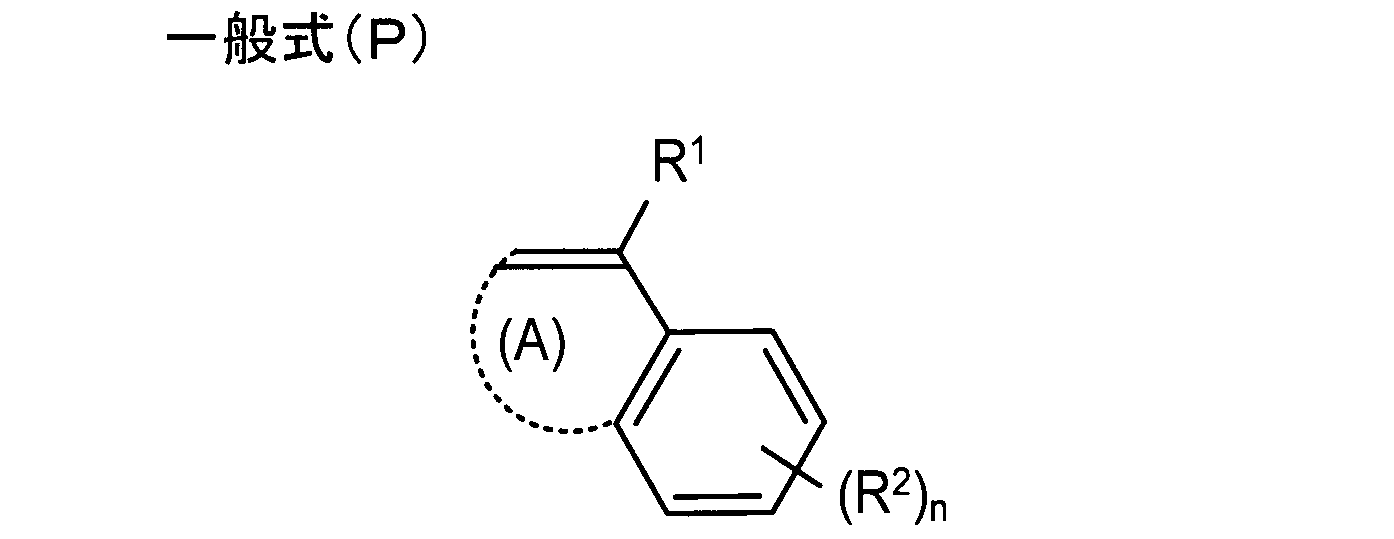
一般式(P)中、R1は水素原子または炭素数1~4の脂肪族基を表す。R1は、特に限定されないが、水素原子、メチル基、又はエチル基であることが好ましい。
In general formula (P), R 1 represents a hydrogen atom or an aliphatic group having 1 to 4 carbon atoms. R 1 is not particularly limited, but is preferably a hydrogen atom, a methyl group, or an ethyl group.
R2は置換基を表し、置換基としては、脂肪族基又は芳香族基が好ましい。R2は、特に限定されないが、脂肪族基としては、アルキル基、アルケニル基、アルキニル基、シクロアルキル基が好ましく、炭素数1~6のアルキル基がより好ましく、メチル基、エチル基、プロピル基、ブチル基が更に好ましく、メチル基、t-ブチル基が特に好ましい。芳香族基としては、フェニル基、ナフチル基、ビフェニル基が好ましく、フェニル基が特に好ましい。
R 2 represents a substituent, and the substituent is preferably an aliphatic group or an aromatic group. R 2 is not particularly limited, but the aliphatic group is preferably an alkyl group, an alkenyl group, an alkynyl group or a cycloalkyl group, more preferably an alkyl group having 1 to 6 carbon atoms, a methyl group, an ethyl group or a propyl group. A butyl group is more preferable, and a methyl group and a t-butyl group are particularly preferable. As the aromatic group, a phenyl group, a naphthyl group, and a biphenyl group are preferable, and a phenyl group is particularly preferable.
nは0~4の整数を表し、0~2が好ましく、0~1がより好ましい。なお、nが0のとき置換基R2が存在しないことになるが、化学式中、ここには水素原子があればよいことを意味する。
n represents an integer of 0 to 4, preferably 0 to 2, and more preferably 0 to 1. Note that when n is 0, the substituent R 2 does not exist, but in the chemical formula, this means that a hydrogen atom is sufficient.
(A)は5または6員環を形成するのに必要な原子群を表し、5または6員の芳香環であることが好ましい。本明細書の芳香環とは、ヘテロ原子を含まない芳香族環とヘテロ原子を有する飽和・不飽和の複素環を含む概念である。
(A) represents an atomic group necessary for forming a 5- or 6-membered ring, and is preferably a 5- or 6-membered aromatic ring. The aromatic ring in this specification is a concept including an aromatic ring containing no hetero atom and a saturated / unsaturated hetero ring containing a hetero atom.
フィルムの透湿度および含水率を抑制効果から、一般式(P)で表わされる重合体の質量平均分子量は200~10,000であることが好ましく、300~8,000であることがより好ましく、400~4,000であることが特に好ましい。フィルムの透湿度および含水率を抑制効果から、上限値以下であると、セルロースアシレートとの相溶性向上が期待できる。
In view of the effect of suppressing the moisture permeability and moisture content of the film, the polymer represented by the general formula (P) preferably has a mass average molecular weight of 200 to 10,000, more preferably 300 to 8,000, Particularly preferred is 400 to 4,000. From the effect of suppressing the moisture permeability and moisture content of the film, an improvement in compatibility with the cellulose acylate can be expected when it is not more than the upper limit.
分子量及び分散度は、特に断らない限り、GPC(ゲルろ過クロマトグラフィー)法を用いて測定した値とし、分子量はポリスチレン換算の質量平均分子量で測定できる。
Unless otherwise specified, the molecular weight and dispersity are values measured using a GPC (gel filtration chromatography) method, and the molecular weight can be measured by a polystyrene-reduced mass average molecular weight.
GPC法に用いるカラムに充填されているゲルは、芳香族化合物を繰り返し単位に持つゲルが好ましく、例えばスチレン-ジビニルベンゼン共重合体からなるゲルが挙げられる。カラムは2~6本連結させて用いることが好ましい。用いる溶媒は、テトラヒドロフラン等のエーテル系溶媒、N-メチルピロリジノン等のアミド系溶媒が挙げられる。測定は、溶媒の流速が0.1~2mL/minの範囲で行うことが好ましく、0.5~1.5mL/minの範囲で行うことが最も好ましい。この範囲内で測定を行うことで、装置に負荷がかからず、さらに効率的に測定ができる。測定温度は10~50℃で行うことが好ましく、20~40℃で行うことが最も好ましい。なお、使用するカラム及びキャリアは測定対象となる高分子化合物の物性に応じて適宜選定することができる。
The gel packed in the column used in the GPC method is preferably a gel having an aromatic compound as a repeating unit, and examples thereof include a gel made of a styrene-divinylbenzene copolymer. Two to six columns are preferably connected and used. Examples of the solvent used include ether solvents such as tetrahydrofuran and amide solvents such as N-methylpyrrolidinone. The measurement is preferably performed at a solvent flow rate in the range of 0.1 to 2 mL / min, and most preferably in the range of 0.5 to 1.5 mL / min. By performing the measurement within this range, the apparatus is not loaded and the measurement can be performed more efficiently. The measurement temperature is preferably 10 to 50 ° C, most preferably 20 to 40 ° C. The column and carrier to be used can be appropriately selected according to the physical properties of the polymer compound to be measured.
一般式(P)で表わされる重合体の添加量は特に限定されないが、フィルム基材を形成する樹脂100質量部に対して、0.1~100質量部であることが好ましく、0.5~50質量部であることがより好ましく、1.0~30質量部であることが特に好ましい。
The addition amount of the polymer represented by the general formula (P) is not particularly limited, but is preferably 0.1 to 100 parts by mass with respect to 100 parts by mass of the resin forming the film substrate, and 0.5 to The amount is more preferably 50 parts by mass, and particularly preferably 1.0 to 30 parts by mass.
以下、一般式(P)で表されるモノマー由来の繰り返し単位を有する重合体の具体例を示すが、本発明はこれに限定して解釈されるものではない。なお、下記の構造式は主要成分の繰り返し単位の化学構造とその構成比を示しており、その他の成分が含まれていてもよいことは上記の通りである。
Hereinafter, although the specific example of the polymer which has a repeating unit derived from the monomer represented by general formula (P) is shown, this invention is limited to this and is not interpreted. In addition, the following structural formula has shown the chemical structure of the repeating unit of the main component, and its structural ratio, and it is as above-mentioned that the other component may be contained.

なお、本明細書の重合体とは、モノマーが多数重合した一般的な高分子化合物であるポリマーに加えて、モノマーが例えば数個重合した分子量数百程度の化合物であるオリゴマーも含まれることを意味する。また特に断らない限り、ポリマー、コポリマーまたは共重合体も含む。
The polymer of the present specification includes not only a polymer that is a general polymer compound in which a large number of monomers are polymerized, but also an oligomer that is a compound having a molecular weight of about several hundreds, in which several monomers are polymerized, for example. means. Unless otherwise specified, polymers, copolymers or copolymers are also included.
(有機酸)
フィルム基材は、偏光子の耐久性改良剤として、有機酸を含有しても良い。有機酸の分子量は200~1000であることが好ましく、250~800であることがより好ましく、280~500であることが特に好ましい。有機酸としては、芳香環構造を含むことが好ましく、炭素数6~12のアリール基を含むことが好ましく、フェニル基を含むことが特に好ましい。有機酸の芳香環構造は、その他の環と縮合環を形成していてもよい。有機酸の芳香環構造は、置換基を有していてもよいが、ハロゲン原子またはアルキル基であることが好ましく、ハロゲン原子または炭素数1~6のアルキル基であることがより好ましく、塩素原子またはメチル基であることが特に好ましい。また、有機酸は、下記一般式(Q)で表されることが好ましい。 (Organic acid)
The film substrate may contain an organic acid as a polarizer durability improver. The molecular weight of the organic acid is preferably 200 to 1000, more preferably 250 to 800, and particularly preferably 280 to 500. The organic acid preferably includes an aromatic ring structure, preferably includes an aryl group having 6 to 12 carbon atoms, and particularly preferably includes a phenyl group. The aromatic ring structure of the organic acid may form a condensed ring with other rings. The aromatic ring structure of the organic acid may have a substituent, but is preferably a halogen atom or an alkyl group, more preferably a halogen atom or an alkyl group having 1 to 6 carbon atoms, and a chlorine atom. Or it is especially preferable that it is a methyl group. The organic acid is preferably represented by the following general formula (Q).

一般式(Q)において、R26はアリール基を表し、R27およびR28はそれぞれ独立して水素原子、アルキル基、アリール基を表す。R26およびR27はそれぞれ置換基を有していてもよい。R26は炭素数6~18のアリール基であることが好ましく、炭素数6~12のアリール基であることがより好ましく、フェニル基であることが特に好ましい。R27およびR28はそれぞれ独立して水素原子、炭素数1~12のアルキル基(シクロアルキル基も含む)または炭素数6~12のアリール基であることが好ましく、水素原子、炭素数1~6のアルキル基(シクロアルキル基も含む)またはフェニル基であることがより好ましく、水素原子、メチル基、エチル基、シクロヘキサン基またはフェニル基であることが特に好ましい。以下に一般式(Q)で表される有機酸の具体例を例示するが、本発明は以下に限定されるものではない。
In the general formula (Q), R 26 represents an aryl group, and R 27 and R 28 each independently represent a hydrogen atom, an alkyl group, or an aryl group. R 26 and R 27 may each have a substituent. R 26 is preferably an aryl group having 6 to 18 carbon atoms, more preferably an aryl group having 6 to 12 carbon atoms, and particularly preferably a phenyl group. R 27 and R 28 are preferably each independently a hydrogen atom, an alkyl group having 1 to 12 carbon atoms (including a cycloalkyl group) or an aryl group having 6 to 12 carbon atoms. It is more preferably an alkyl group of 6 (including a cycloalkyl group) or a phenyl group, and particularly preferably a hydrogen atom, a methyl group, an ethyl group, a cyclohexane group or a phenyl group. Specific examples of the organic acid represented by the general formula (Q) are illustrated below, but the present invention is not limited to the following.

有機酸の含有量としては、フィルム基材を構成する主成分の樹脂に対して1~20質量%であることが好ましい。
The content of the organic acid is preferably 1 to 20% by mass with respect to the main component resin constituting the film substrate.
(一般式(S)で表される化合物)
フィルム基材は、偏光子の耐久性改良剤として、以下の一般式(S)で表される化合物を含有してもよい。 (Compound represented by formula (S))
A film base material may contain the compound represented by the following general formula (S) as a durability improvement agent of a polarizer.
フィルム基材は、偏光子の耐久性改良剤として、以下の一般式(S)で表される化合物を含有してもよい。 (Compound represented by formula (S))
A film base material may contain the compound represented by the following general formula (S) as a durability improvement agent of a polarizer.

一般式(S)において、R1は水素原子又は置換基を表し、R2は下記一般式(a)で表される置換基を表す。n1は0~4の整数を表す。n1が2以上のとき、複数のR1は互いに同一であっても異なっていてもよい。n2は1~5の整数を表す。n2が2以上のとき、複数のR2は互いに同一であっても異なっていてもよい。
In the general formula (S), R 1 represents a hydrogen atom or a substituent, and R 2 represents a substituent represented by the following general formula (a). n1 represents an integer of 0 to 4. When n1 is 2 or more, the plurality of R 1 may be the same as or different from each other. n2 represents an integer of 1 to 5. When n2 is 2 or more, the plurality of R 2 may be the same as or different from each other.

一般式(a)において、Aは置換又は無置換の芳香族環を表す。R3及びR4は、それぞれ独立に、水素原子、炭素原子数1~5のアルキル基又は下記の一般式(b)で表される置換基を表す。R5は、単結合又は炭素原子数1~5のアルキレン基を表す。Xは、置換又は無置換の芳香族環を表す。n3は0~10の整数を表す。n3が2以上のとき、複数のR5及びXは互いに同一であっても異なっていてもよい。
In general formula (a), A represents a substituted or unsubstituted aromatic ring. R 3 and R 4 each independently represent a hydrogen atom, an alkyl group having 1 to 5 carbon atoms, or a substituent represented by the following general formula (b). R 5 represents a single bond or an alkylene group having 1 to 5 carbon atoms. X represents a substituted or unsubstituted aromatic ring. n3 represents an integer of 0 to 10. When n3 is 2 or more, the plurality of R 5 and X may be the same as or different from each other.

一般式(b)において、Xは、置換又は無置換の芳香族環を表す。R6、R7、R8、及びR9は、それぞれ独立に水素原子又は炭素原子数1~5のアルキル基を表す。n5は1~11の整数を表す。n5が2以上のとき、複数のR6、R7、R8及びXは互いに同一であっても異なっていてもよい。
In general formula (b), X represents a substituted or unsubstituted aromatic ring. R 6 , R 7 , R 8 and R 9 each independently represents a hydrogen atom or an alkyl group having 1 to 5 carbon atoms. n5 represents an integer of 1 to 11. When n5 is 2 or more, the plurality of R 6 , R 7 , R 8 and X may be the same as or different from each other.
以下、一般式(S)で表される化合物の具体例を示すが、化合物はこれらに限定されるわけではない。
Hereinafter, specific examples of the compound represented by the general formula (S) are shown, but the compound is not limited thereto.


一般式(S)で表される化合物の重量平均分子量は200~1200であることが溶解から好ましく、250~1000であることがより好ましく、300~800であることが特に好ましい。
The weight average molecular weight of the compound represented by the general formula (S) is preferably from 200 to 1,200, more preferably from 250 to 1,000, and particularly preferably from 300 to 800.
一般式(S)で表される化合物の添加量は特に限定されないが、フィルム基材100質量部に対して、0.1~100質量部であることが安定性から好ましく、0.2~80質量部であることがより好ましく、0.3~60質量部であることが特に好ましい。
The addition amount of the compound represented by the general formula (S) is not particularly limited, but is preferably from 0.1 to 100 parts by mass with respect to 100 parts by mass of the film base material, and is preferably from 0.2 to 80 The amount is more preferably part by mass, and particularly preferably 0.3 to 60 parts by mass.
(欠点)
フィルム基材は、直径5μm以上の欠点が1個/10cm四方以下であることが好ましい。更に好ましくは0.5個/10cm四方以下、一層好ましくは0.1個/10cm四方以下である。ここで欠点の直径とは、欠点が円形の場合はその直径を示し、円形でない場合は欠点の範囲を下記方法により顕微鏡で観察して決定し、その最大径(外接円の直径)とする。 (Disadvantage)
The film substrate preferably has a defect of 5 μm or more in diameter of 1 piece / 10 cm square or less. More preferably, it is 0.5 piece / 10 cm square or less, more preferably 0.1 piece / 10 cm square or less. Here, the diameter of the defect indicates the diameter when the defect is circular, and when the defect is not circular, the range of the defect is determined by observing with a microscope by the following method, and the maximum diameter (diameter of circumscribed circle) is determined.
欠点の範囲は、欠点が気泡や異物の場合は、欠点を微分干渉顕微鏡の透過光で観察したときの影の大きさである。欠点が、ローラ傷の転写や擦り傷など、表面形状の変化の場合は、欠点を微分干渉顕微鏡の反射光で観察して大きさを確認できる。
The range of the defect is the size of the shadow when the defect is observed with the transmitted light of the differential interference microscope when the defect is a bubble or a foreign object. When the defect is a change in the surface shape such as transfer of a roller scratch or an abrasion, the size can be confirmed by observing the defect with the reflected light of a differential interference microscope.
欠点の個数が1個/10cm四方より多いと、例えば後工程での加工時などでフィルムに張力がかかると、欠点を基点としてフィルムが破断して生産性が低下する場合がある。また、欠点の直径が5μm以上になると、偏光板観察などにより目視で確認でき、光学部材として用いたとき輝点が生じる場合がある。
When the number of defects is more than 1/10 cm square, for example, when a tension is applied to the film during processing in a later process, the film may be broken with the defect as a starting point and productivity may be reduced. Moreover, when the diameter of a defect becomes 5 micrometers or more, it can confirm visually by polarizing plate observation etc., and when used as an optical member, a bright spot may arise.
また、目視で確認できない場合でも、ハードコート層を形成したときに、塗膜が均一に形成できず欠点(塗布抜け)となる場合がある。ここで、欠点とは、溶液製膜の乾燥工程において溶媒の急激な蒸発に起因して発生するフィルム中の空洞(発泡欠点)や、製膜原液中の異物や製膜中に混入する異物に起因するフィルム中の異物(異物欠点)を言う。また、フィルム基材は、JIS-K7127-1999に準拠した測定において、少なくとも一方向の破断伸度が、10%以上であることが好ましく、より好ましくは20%以上である。破断伸度の上限は特に限定されるものではないが、現実的には250%程度である。破断伸度を大きくするには異物や発泡に起因するフィルム中の欠点を抑制することが有効である。
In addition, even when it cannot be visually confirmed, when the hard coat layer is formed, the coating film may not be formed uniformly, resulting in a defect (missing coating). Here, the defect is a void in the film (foaming defect) generated due to the rapid evaporation of the solvent in the drying process of the solution casting, a foreign matter in the film forming stock solution, or a foreign matter mixed in the film forming. This refers to the foreign matter (foreign matter defect) in the film. Further, the film base material preferably has a breaking elongation of at least one direction of 10% or more, more preferably 20% or more in the measurement based on JIS-K7127-1999. The upper limit of the elongation at break is not particularly limited, but is practically about 250%. In order to increase the elongation at break, it is effective to suppress defects in the film caused by foreign matter and foaming.
(光学特性)
フィルム基材は、その全光線透過率が90%以上であることが好ましく、より好ましくは92%以上である。また、現実的な上限としては、99%程度である。ヘイズ値は2%以下が好ましく、より好ましくは1.5%以下である。全光線透過率、ヘイズ値はJIS K7361及びJIS K7136に準じて測定することができる。 (optical properties)
The film substrate preferably has a total light transmittance of 90% or more, more preferably 92% or more. Moreover, as a realistic upper limit, it is about 99%. The haze value is preferably 2% or less, more preferably 1.5% or less. The total light transmittance and haze value can be measured according to JIS K7361 and JIS K7136.
また、フィルム基材の面内リタデーション値Roは0~5nm、厚さ方向のリタデーション値Rthが-10~10nmの範囲が好ましい。更にRthは-5~5nmの範囲が好ましくい。或いはレターデーションRoが30~200nmの範囲であることが好ましく、30~90nmの範囲であることが更に好ましい。厚み方向のレターデーションRthは70~300nmの範囲であることが好ましい。
The in-plane retardation value Ro of the film base is preferably 0 to 5 nm, and the retardation value Rth in the thickness direction is preferably in the range of −10 to 10 nm. Further, Rth is preferably in the range of -5 to 5 nm. Alternatively, the retardation Ro is preferably in the range of 30 to 200 nm, and more preferably in the range of 30 to 90 nm. The retardation Rth in the thickness direction is preferably in the range of 70 to 300 nm.
面内リタデーションRo値は下記式(I)に定義され、厚さ方向のリタデーション値Rthは下記式(II)により定義される。
式(I) Ro=(nx-ny)×d
式(II) Rth={(nx+ny)/2-nz}×d
(式中、nxはフィルム基材の面内の遅相軸方向の屈折率、nyはフィルム基材面内で遅相軸に直交する方向の屈折率、nzはフィルム基材の厚さ方向の屈折率、dはフィルム基材の厚さ(nm)をそれぞれ表す。) The in-plane retardation Ro value is defined by the following formula (I), and the retardation value Rth in the thickness direction is defined by the following formula (II).
Formula (I) Ro = (nx−ny) × d
Formula (II) Rth = {(nx + ny) / 2−nz} × d
(Where nx is the refractive index in the slow axis direction in the plane of the film base, ny is the refractive index in the direction perpendicular to the slow axis in the plane of the film base, and nz is the thickness direction of the film base) (Refractive index, d represents the thickness (nm) of the film substrate, respectively.)
上記リタデーションは、例えばKOBRA-21ADH(王子計測機器(株)製)を用いて、23℃、55%RH(相対湿度)の環境下で、波長が590nmで求めることができる。
The retardation can be obtained at a wavelength of 590 nm under an environment of 23 ° C. and 55% RH (relative humidity) using, for example, KOBRA-21ADH (manufactured by Oji Scientific Instruments).
〔セルロースエステルフィルムの製膜〕
次に、フィルム基材の一例であるセルロースエステルフィルムの製膜方法の例を説明するが、製膜方法はこれに限定されるものではない。セルロースエステルフィルムの製膜方法としては、インフレーション法、T-ダイ法、カレンダー法、切削法、流延法、エマルジョン法、ホットプレス法等の製造法が使用できる。 [Film formation of cellulose ester film]
Next, although the example of the film forming method of the cellulose-ester film which is an example of a film base material is demonstrated, the film forming method is not limited to this. As a method for producing a cellulose ester film, a production method such as an inflation method, a T-die method, a calendar method, a cutting method, a casting method, an emulsion method, a hot press method, or the like can be used.
(有機溶媒)
セルロースエステルフィルムを後述する溶液流延製膜法で製造する場合の樹脂溶液(ドープ組成物)を形成するのに有用な有機溶媒は、セルロースエステル樹脂、その他の添加剤を同時に溶解するものであれば制限なく用いることができる。例えば、塩素系有機溶媒としては、塩化メチレン、非塩素系有機溶媒としては、酢酸メチル、酢酸エチル、酢酸アミル、アセトン、テトラヒドロフラン、1,3-ジオキソラン、1,4-ジオキサン、シクロヘキサノン、ギ酸エチル、2,2,2-トリフルオロエタノール、2,2,3,3-ヘキサフルオロ-1-プロパノール、1,3-ジフルオロ-2-プロパノール、1,1,1,3,3,3-ヘキサフルオロ-2-メチル-2-プロパノール、1,1,1,3,3,3-ヘキサフルオロ-2-プロパノール、2,2,3,3,3-ペンタフルオロ-1-プロパノール、ニトロエタン、メタノール、エタノール、n-プロパノール、iso-プロパノール、n-ブタノール、sec-ブタノール、tert-ブタノール等を挙げることができ、塩化メチレン、酢酸メチル、酢酸エチル、アセトンを好ましく使用し得る。前記溶媒はセルロースエステル樹脂、その他添加剤を計15~45質量%溶解させたドープ組成物であることが好ましい。 (Organic solvent)
An organic solvent useful for forming a resin solution (dope composition) in the case of producing a cellulose ester film by a solution casting film forming method described later is one that can simultaneously dissolve a cellulose ester resin and other additives. Can be used without limitation. For example, as a chlorinated organic solvent, methylene chloride, as a non-chlorinated organic solvent, methyl acetate, ethyl acetate, amyl acetate, acetone, tetrahydrofuran, 1,3-dioxolane, 1,4-dioxane, cyclohexanone, ethyl formate, 2,2,2-trifluoroethanol, 2,2,3,3-hexafluoro-1-propanol, 1,3-difluoro-2-propanol, 1,1,1,3,3,3-hexafluoro- 2-methyl-2-propanol, 1,1,1,3,3,3-hexafluoro-2-propanol, 2,2,3,3,3-pentafluoro-1-propanol, nitroethane, methanol, ethanol, n-propanol, iso-propanol, n-butanol, sec-butanol, tert-butanol, etc. Can, methylene chloride, methyl acetate, ethyl acetate, may be used preferably acetone. The solvent is preferably a dope composition in which a total of 15 to 45 mass% of cellulose ester resin and other additives are dissolved.
(溶液流延製膜法)
溶液流延製膜法では、樹脂及び添加剤を溶剤に溶解させてドープを調製する工程、ドープをベルト状もしくはドラム状の金属支持体上に流延する工程、流延したドープをウェブとして乾燥する工程、金属支持体から剥離する工程、延伸又は幅保持する工程、更に乾燥する工程、仕上がったセルロースエステルフィルムを巻き取る工程により行われる。 (Solution casting film forming method)
In the solution casting film forming method, a step of preparing a dope by dissolving a resin and an additive in a solvent, a step of casting the dope on a belt-shaped or drum-shaped metal support, and drying the cast dope as a web It is carried out by a step of peeling off from the metal support, a step of stretching or maintaining the width, a step of further drying, and a step of winding up the finished cellulose ester film.
金属支持体としては、ステンレススティールベルト若しくは鋳物で表面をメッキ仕上げしたドラムが好ましく用いられる。
As the metal support, a stainless steel belt or a drum whose surface is plated with a casting is preferably used.
キャスト(流延)の幅は1~4mとすることができる。流延工程の金属支持体の表面温度は-50℃~溶剤が沸騰して発泡しない温度以下に設定される。温度が高い方がウェブの乾燥速度が速くできるので好ましいが、余り高すぎるとウェブが発泡したり、平面性が劣化する場合がある。
The width of the cast (casting) can be 1 to 4 m. The surface temperature of the metal support in the casting step is set to −50 ° C. to below the temperature at which the solvent boils and does not foam. A higher temperature is preferred because the web can be dried faster, but if it is too high, the web may foam or the flatness may deteriorate.
好ましい支持体温度としては0~100℃で適宜決定され、5~30℃が更に好ましい。又は、冷却することによってウェブをゲル化させて残留溶媒を多く含んだ状態でドラムから剥離することも好ましい方法である。金属支持体の温度を制御する方法は特に制限されないが、温風又は冷風を吹きかける方法や、温水を金属支持体の裏側に接触させる方法がある。温水を用いる方が熱の伝達が効率的に行われるため、金属支持体の温度が一定になるまでの時間が短く好ましい。
A preferable support temperature is appropriately determined at 0 to 100 ° C., and more preferably 5 to 30 ° C. Alternatively, it is also a preferable method that the web is gelled by cooling and peeled from the drum in a state containing a large amount of residual solvent. The method for controlling the temperature of the metal support is not particularly limited, and there are a method of blowing warm air or cold air, and a method of contacting hot water with the back side of the metal support. It is preferable to use warm water because heat transfer is performed efficiently, so that the time until the temperature of the metal support becomes constant is short.
温風を用いる場合は溶媒の蒸発潜熱によるウェブの温度低下を考慮して、溶媒の沸点以上の温風を使用しつつ、発泡も防ぎながら目的の温度よりも高い温度の風を使う場合がある。
When using warm air, considering the temperature drop of the web due to the latent heat of vaporization of the solvent, while using warm air above the boiling point of the solvent, there may be cases where wind at a temperature higher than the target temperature is used while preventing foaming. .
特に、流延から剥離するまでの間で支持体の温度及び乾燥風の温度を変更し、効率的に乾燥を行うことが好ましい。
In particular, it is preferable to efficiently dry by changing the temperature of the support and the temperature of the drying air during the period from casting to peeling.
セルロースエステルフィルムが良好な平面性を得るためには、金属支持体からウェブを剥離する際の残留溶媒量が10~150質量%であることが好ましく、更に好ましくは20~40質量%又は60~130質量%であり、特に好ましくは、20~30質量%又は70~120質量%である。残留溶媒量は下記式で定義される。
残留溶媒量(質量%)={(M-N)/N}×100
なお、Mはウェブ又はフィルムを製造中又は製造後の任意の時点で採取した試料の質量で、Nは質量Mのものを115℃で1時間の加熱後の質量である。 In order for the cellulose ester film to obtain good flatness, the residual solvent amount when peeling the web from the metal support is preferably 10 to 150% by mass, more preferably 20 to 40% by mass or 60 to 60%. It is 130% by mass, particularly preferably 20 to 30% by mass or 70 to 120% by mass. The amount of residual solvent is defined by the following formula.
Residual solvent amount (% by mass) = {(MN) / N} × 100
In addition, M is the mass of the sample collected at any time during or after the production of the web or film, and N is the mass after heating at 115 ° C. for 1 hour.
セルロースエステルフィルムの乾燥工程では、ウェブを金属支持体より剥離し、乾燥し、残留溶媒量を1質量%以下にすることが好ましく、更に好ましくは0.1質量%以下であり、特に好ましくは0~0.01質量%以下である。
In the drying step of the cellulose ester film, the web is peeled off from the metal support and dried to make the residual solvent amount 1% by mass or less, more preferably 0.1% by mass or less, and particularly preferably 0. -0.01 mass% or less.
フィルム乾燥工程では、一般にローラ乾燥方式(上下に配置した多数のローラにウェブを交互に通し乾燥させる方式)やテンター方式でウェブを搬送させながら乾燥する方式が採られる。
In the film drying process, generally, a roller drying method (a method in which webs are alternately passed through a plurality of rollers arranged above and below) and a method in which the web is dried while being conveyed by a tenter method are employed.
延伸工程では、フィルムの長手方向(MD方向)、及び幅手方向(TD方向)に対して、逐次又は同時に延伸することができる。互いに直交する2軸方向の延伸倍率は、それぞれ最終的にはMD方向に1.0~2.0倍、TD方向に1.05~2.0倍の範囲とすることが好ましく、MD方向に1.0~1.5倍、TD方向に1.05~2.0倍の範囲で行うことがさらに好ましい。例えば、複数のローラに周速差をつけ、その間でローラ周速差を利用してMD方向に延伸する方法、ウェブの両端をクリップやピンで固定し、クリップやピンの間隔を進行方向に広げてMD方向に延伸する方法、同様に横方向に広げてTD方向に延伸する方法、或いはMD方向及びTD方向を同時に広げて両方向に延伸する方法等が挙げられる。
In the stretching step, the film can be sequentially or simultaneously stretched in the longitudinal direction (MD direction) and the lateral direction (TD direction). The draw ratios in the biaxial directions perpendicular to each other are preferably in the range of 1.0 to 2.0 times in the MD direction and 1.05 to 2.0 times in the TD direction, respectively. More preferably, it is carried out in the range of 1.0 to 1.5 times and 1.05 to 2.0 times in the TD direction. For example, a method of making a difference in peripheral speed between a plurality of rollers and stretching in the MD direction using the difference in peripheral speed of the roller between them, fixing both ends of the web with clips and pins, and widening the interval between the clips and pins in the traveling direction And a method of stretching in the MD direction, a method of stretching in the lateral direction and stretching in the TD direction, a method of stretching the MD direction and the TD direction simultaneously, and stretching in both directions.
製膜工程のこれらの幅保持或いは幅手方向の延伸はテンターによって行うことが好ましく、ピンテンターでもクリップテンターでもよい。
It is preferable to perform the width maintenance or the stretching in the width direction in the film forming process by a tenter, and it may be a pin tenter or a clip tenter.
テンター等の製膜工程でのフィルム搬送張力は、温度にもよるが、120~200N/mが好ましく、140~200N/mが更に好ましく、140~160N/mが最も好ましい。
The film transport tension in the film forming process such as a tenter is preferably 120 to 200 N / m, more preferably 140 to 200 N / m, and most preferably 140 to 160 N / m, although it depends on the temperature.
延伸する際の温度は、セルロースエステルフィルムのガラス転移温度をTgとすると(Tg-30)~(Tg+100)℃、より好ましくは(Tg-20)~(Tg+80)℃、更に好ましく(Tg-5)~(Tg+20)℃である。
The stretching temperature is (Tg-30) to (Tg + 100) ° C., more preferably (Tg-20) to (Tg + 80) ° C., more preferably (Tg-5), where Tg is the glass transition temperature of the cellulose ester film. ~ (Tg + 20) ° C.
セルロースエステルフィルムのTgは、フィルムを構成する材料種及び構成する材料の比率によって制御することができる。セルロースエステルフィルムの乾燥時のTgは、110℃以上が好ましく、更に120℃以上が好ましい。特に好ましくは150℃以上である。ガラス転移温度は190℃以下、より好ましくは170℃以下であることが好ましい。セルロースエステルフィルムのTgはJIS K7121に記載の方法等によって求めることができる。延伸する際の温度は、150℃以上、延伸倍率は1.15倍以上にすると、表面が適度に粗れるため、好ましい。セルロースエステルフィルム表面を粗らすことにより、滑り性が向上するとともに、表面加工性が向上するため好ましい。
The Tg of the cellulose ester film can be controlled by the material type constituting the film and the ratio of the constituting materials. The Tg when the cellulose ester film is dried is preferably 110 ° C. or higher, more preferably 120 ° C. or higher. Especially preferably, it is 150 degreeC or more. The glass transition temperature is preferably 190 ° C. or lower, more preferably 170 ° C. or lower. The Tg of the cellulose ester film can be determined by the method described in JIS K7121. The stretching temperature is preferably 150 ° C. or more and the stretching ratio is 1.15 times or more because the surface is appropriately roughened. Roughening the surface of the cellulose ester film is preferable because it improves slipperiness and improves surface processability.
(溶融流延製膜法)
セルロースエステルフィルムは、溶融流延製膜法によって製膜しても良い。溶融流延製膜法は、セルロースエステル樹脂、可塑剤等のその他の添加剤を含む組成物を、流動性を示す温度まで加熱溶融し、その後、流動性のセルロースエステルを含む溶融物を流延することをいう。 (Melt casting method)
The cellulose ester film may be formed by a melt casting film forming method. In the melt casting film forming method, a composition containing other additives such as a cellulose ester resin and a plasticizer is heated and melted to a temperature showing fluidity, and then a melt containing the fluid cellulose ester is cast. To do.
溶融流延製膜法では、機械的強度及び表面精度等の点から、溶融押出し法が好ましい。溶融押出しに用いる複数の原材料は、通常予め混錬してペレット化しておくことが好ましい。
In the melt casting film forming method, the melt extrusion method is preferable from the viewpoint of mechanical strength and surface accuracy. It is preferable that a plurality of raw materials used for melt extrusion are usually kneaded in advance and pelletized.
ペレット化は、公知の方法でよく、例えば、乾燥セルロースエステルや可塑剤、その他添加剤をフィーダーで押出し機に供給して1軸や2軸の押出し機を用いて混錬し、ダイからストランド状に押出し、水冷又は空冷し、カッティングすることでできる。
Pelletization may be performed by a known method, for example, dry cellulose ester, plasticizer, and other additives are fed to an extruder with a feeder, kneaded using a single or twin screw extruder, and formed into a strand from a die. Can be extruded, water-cooled or air-cooled, and then cut.
添加剤は、押出し機に供給する前に混合しておいてもよいし、それぞれ個別のフィーダーで供給してもよい。
Additives may be mixed before being supplied to the extruder, or may be supplied by individual feeders.
粒子や酸化防止剤等の少量の添加剤は、均一に混合するため、事前に混合しておくことが好ましい。
A small amount of additives such as particles and antioxidants are preferably mixed in advance in order to mix uniformly.
押出し機は、剪断力を抑え、樹脂が劣化(分子量低下、着色、ゲル生成等)しないように、ペレット化できる程度になるべく低温で加工することが好ましい。例えば、2軸押出し機の場合、深溝タイプのスクリューを用いて、同方向に回転させることが好ましい。混錬の均一性から、噛み合いタイプが好ましい。
The extruder is preferably processed at a temperature as low as possible so that it can be pelletized so that the shearing force is suppressed and the resin does not deteriorate (molecular weight reduction, coloring, gel formation, etc.). For example, in the case of a twin screw extruder, it is preferable to rotate in the same direction using a deep groove type screw. From the uniformity of kneading, the meshing type is preferable.
以上のようにして得られたペレットを用いてフィルム製膜を行う。もちろんペレット化せず、原材料の粉末をそのままフィーダーで押出し機に供給し、そのままフィルム製膜することも可能である。
Film formation is performed using the pellets obtained as described above. Of course, the raw material powder can be directly fed to the extruder by a feeder without being pelletized to form a film as it is.
上記ペレットを1軸や2軸タイプの押出し機を用いて、押出す際の溶融温度を200~300℃程度とし、リーフディスクタイプのフィルター等で濾過し異物を除去した後、Tダイからフィルム状に流延し、冷却ローラと弾性タッチローラでフィルムをニップし、冷却ローラ上で固化させることにより、セルロースエステルフィルムを製膜する。
Using a single-screw or twin-screw extruder, the pellets are melted at a temperature of about 200 to 300 ° C, filtered through a leaf disk filter, etc. to remove foreign matter, and then formed into a film from the T die. The cellulose ester film is formed by niping the film with a cooling roller and an elastic touch roller and solidifying the film on the cooling roller.
供給ホッパーから押出し機へ導入する際は、真空下又は減圧下や不活性ガス雰囲気下にして酸化分解等を防止することが好ましい。
When introducing from the supply hopper to the extruder, it is preferable to prevent oxidative decomposition and the like under vacuum, reduced pressure, or inert gas atmosphere.
押出し流量は、ギヤポンプを導入する等して安定に調整することが好ましい。また、異物の除去に用いるフィルターには、ステンレス繊維焼結フィルターが好ましく用いられる。ステンレス繊維焼結フィルターは、ステンレス繊維体を複雑に絡み合った状態を作り出した上で圧縮し接触箇所を焼結し一体化したもので、その繊維の太さと圧縮量により密度を変え、濾過精度を調整できる。
The extrusion flow rate is preferably adjusted stably by introducing a gear pump or the like. Further, a stainless fiber sintered filter is preferably used as a filter used for removing foreign substances. The stainless steel fiber sintered filter is a united stainless steel fiber body that is intricately intertwined and compressed, and the contact points are sintered and integrated. The density of the fiber is changed depending on the thickness of the fiber and the amount of compression, and the filtration accuracy is improved. Can be adjusted.
可塑剤や粒子等の添加剤は、予め樹脂と混合しておいてもよいし、押出し機の途中で練り込んでもよい。均一に添加するために、スタチックミキサー等の混合装置を用いることが好ましい。
Additives such as plasticizers and particles may be mixed with the resin in advance, or may be kneaded in the middle of the extruder. In order to add uniformly, it is preferable to use a mixing apparatus such as a static mixer.
冷却ローラと弾性タッチローラでセルロースエステルフィルムをニップする際のタッチローラ側のセルロースエステルフィルム温度は、フィルムのTg以上(Tg+110℃)以下にすることが好ましい。このような目的で使用する弾性体表面を有するローラは、公知のローラを使用できる。
The cellulose ester film temperature on the touch roller side when the cellulose ester film is nipped by the cooling roller and the elastic touch roller is preferably Tg or more (Tg + 110 ° C.) or less of the film. A known roller can be used as the roller having an elastic surface used for such a purpose.
弾性タッチローラは挟圧回転体ともいう。弾性タッチローラとしては、市販されているものを用いることもできる。
The elastic touch roller is also called a pinching rotator. A commercially available elastic touch roller can also be used.
冷却ローラからセルロースエステルフィルムを剥離する際は、張力を制御してフィルムの変形を防止することが好ましい。
When peeling the cellulose ester film from the cooling roller, it is preferable to control the tension to prevent deformation of the film.
また、上記のようにして得られたセルロースエステルフィルムは、冷却ローラに接する工程を通過後、前記延伸操作により延伸することが好ましい。
Moreover, it is preferable that the cellulose ester film obtained as described above is stretched by the stretching operation after passing through the step of contacting the cooling roller.
延伸する方法は、公知のローラ延伸機やテンター等を好ましく用いることができる。延伸温度は、通常フィルムを構成する樹脂のTg~(Tg+60)℃の温度範囲で行われることが好ましい。
As the stretching method, a known roller stretching machine or tenter can be preferably used. The stretching temperature is usually preferably in the temperature range of Tg to (Tg + 60) ° C. of the resin constituting the film.
巻き取る前に、製品となる幅に端部をスリットして裁ち落とし、巻き中の貼り付きや、すり傷防止のために、ナール加工(エンボッシング加工)を両端に施してもよい。ナール加工の方法は凹凸のパターンを側面に有する金属リングを用いて加熱や加圧をすることにより加工することができる。フィルム両端部のクリップの把持部分は通常、セルロースエステルフィルムが変形しており、製品として使用できないので切除され、再利用される。
Before winding, the end may be slit and trimmed to the width of the product, and knurled (embossed) may be applied to both ends to prevent sticking and scratching during winding. The knurling method can be performed by heating or pressurizing using a metal ring having an uneven pattern on the side surface. The grip portion of the clip at both ends of the film is usually cut out and reused because the cellulose ester film is deformed and cannot be used as a product.
〔斜め延伸フィルムの製造方法〕
前述のλ/4フィルムは、下記斜め延伸により製造することができる。斜め延伸フィルムの製造方法としては、フィルムの延長方向に対して0°を超え90°未満の角度に遅相軸を有する延伸フィルムを製造することで作製できる。なお、斜め延伸前の未延伸フィルムとしては、前述した公知のフィルムを用いる。 [Method for producing obliquely stretched film]
The aforementioned λ / 4 film can be produced by the following oblique stretching. The oblique stretched film can be produced by producing a stretched film having a slow axis at an angle of more than 0 ° and less than 90 ° with respect to the film extension direction. In addition, as a non-stretched film before diagonal stretching, the well-known film mentioned above is used.
ここで、フィルムの延長方向に対する角度とは、フィルム面内における角度である。遅相軸は、通常延伸方向又は延伸方向に直角な方向に発現するので、フィルムの延長方向に対して0°を超え90°未満の角度で延伸を行うことにより、かかる遅相軸を有する延伸フィルムを製造できる。
Here, the angle with respect to the extending direction of the film is an angle in the film plane. Since the slow axis is usually expressed in the stretching direction or a direction perpendicular to the stretching direction, stretching having such a slow axis is performed by stretching at an angle of more than 0 ° and less than 90 ° with respect to the extending direction of the film. A film can be manufactured.
フィルムの延長方向と遅相軸とがなす角度(配向角θ)は、0°を超え90°未満の範囲で、所望の角度に任意に設定することができるが、より好ましくは10°~80°、更に好ましくは40°~50°である。
The angle between the film extension direction and the slow axis (orientation angle θ) can be arbitrarily set to a desired angle in the range of more than 0 ° and less than 90 °, more preferably 10 ° to 80 °. °, more preferably 40 ° to 50 °.
(斜め延伸)
斜め延伸フィルムは、斜め延伸装置(斜め延伸テンター)を用いて作製することができる。斜め延伸テンターとしては、レールパターンを多様に変化させることにより、フィルムの配向角を自在に設定でき、さらに、フィルムの配向軸をフィルム幅手方向に渡って左右均等に高精度に配向させることができ、かつ、高精度でフィルム厚みやリタデーションを制御できる装置を好ましく用いることができる。次いで、具体的な斜め延伸フィルムの製造方法について図面を用いて説明する。 (Diagonal stretching)
The obliquely stretched film can be produced using an obliquely stretching apparatus (obliquely stretched tenter). As an obliquely stretched tenter, the orientation angle of the film can be set freely by changing the rail pattern in various ways, and furthermore, the orientation axis of the film can be oriented with high precision evenly on the left and right across the width direction of the film. An apparatus capable of controlling the film thickness and retardation with high accuracy can be preferably used. Next, a specific method for producing an obliquely stretched film will be described with reference to the drawings.
図2は、斜め延伸フィルムの製造装置51の概略の構成を模式的に示す平面図である。製造装置51は、長尺フィルムの搬送方向上流側から順に、フィルム繰り出し部52と、搬送方向変更部53と、ガイドロール54と、延伸部55と、ガイドロール56と、搬送方向変更部57と、フィルム切断装置58と、フィルム巻き取り部59とを備えている。なお、延伸部55の詳細については後述する。
FIG. 2 is a plan view schematically showing a schematic configuration of a manufacturing apparatus 51 for an obliquely stretched film. The manufacturing apparatus 51 includes, in order from the upstream side in the transport direction of the long film, a film feeding unit 52, a transport direction changing unit 53, a guide roll 54, a stretching unit 55, a guide roll 56, and a transport direction changing unit 57. A film cutting device 58 and a film take-up unit 59 are provided. Details of the extending portion 55 will be described later.
フィルム繰り出し部52は、上述した長尺フィルムを繰り出して延伸部55に供給するものである。このフィルム繰り出し部52は、長尺フィルムの製膜装置と別体で構成されていてもよいし、一体的に構成されてもよい。前者の場合、長尺フィルムを製膜後に一度巻芯に巻き取って巻回体(長尺フィルム原反)となったものをフィルム繰り出し部52に装填することで、フィルム繰り出し部52から長尺フィルムが繰り出される。一方、後者の場合、フィルム繰り出し部52は、長尺フィルムの製膜後、その長尺フィルムを巻き取ることなく、延伸部55に対して繰り出すことになる。
The film feeding unit 52 feeds the above-mentioned long film and supplies it to the stretching unit 55. The film feeding portion 52 may be configured separately from the long film forming apparatus or may be configured integrally. In the case of the former, a long film is wound around a core once after film formation, and a wound body (long film original fabric) is loaded into the film unwinding part 52 so that the film unwinds from the film unwinding part 52. The film is paid out. On the other hand, in the latter case, the film feeding portion 52 is fed to the stretching portion 55 without winding the long film after the long film is formed.
搬送方向変更部53は、フィルム繰り出し部52から繰り出される長尺フィルムの搬送方向を、斜め延伸テンターとしての延伸部55の入口に向かう方向に変更するものである。このような搬送方向変更部53は、例えばフィルムを搬送しながら折り返すことによって搬送方向を変更するターンバーや、そのターンバーをフィルムに平行な面内で回転させる回転テーブルを含んで構成されている。
The conveyance direction changing unit 53 changes the conveyance direction of the long film fed from the film feeding unit 52 to a direction toward the entrance of the stretching unit 55 as an oblique stretching tenter. Such a conveyance direction change part 53 is comprised including the turntable which rotates the turn bar in the surface parallel to a film, and the turn bar which changes a conveyance direction by folding, for example, conveying a film.
搬送方向変更部53にて長尺フィルムの搬送方向を上記のように変更することにより、製造装置51全体の幅をより狭くすることが可能となるほか、フィルムの送り出し位置および角度を細かく制御することが可能となり、膜厚、光学値のバラツキが小さい長尺斜め延伸フィルムを得ることが可能となる。また、フィルム繰り出し部52および搬送方向変更部53を移動可能(スライド可能、旋回可能)とすれば、延伸部55において長尺フィルムの幅手方向の両端部を挟む左右のクリップ(把持具)のフィルムへの噛込み不良を有効に防止することができる。
By changing the transport direction of the long film as described above by the transport direction changing unit 53, the width of the entire manufacturing apparatus 51 can be made narrower, and the film feed position and angle are finely controlled. Thus, it is possible to obtain a long obliquely stretched film with small variations in film thickness and optical value. In addition, if the film feeding unit 52 and the conveyance direction changing unit 53 are movable (slidable and turnable), the left and right clips (gripping tools) sandwiching both ends in the width direction of the long film in the stretching unit 55 are arranged. It is possible to effectively prevent the biting into the film.
なお、上記したフィルム繰り出し部52は、延伸部55の入口に対して所定角度で長尺フィルムを送り出せるように、スライドおよび旋回可能となっていてもよい。この場合は、搬送方向変更部53の設置を省略した構成とすることもできる。
In addition, the above-described film feeding unit 52 may be slidable and turnable so that a long film can be fed at a predetermined angle with respect to the entrance of the stretching unit 55. In this case, it is also possible to adopt a configuration in which the installation of the conveyance direction changing unit 53 is omitted.
ガイドロール54は、長尺フィルムの走行時の軌道を安定させるために、延伸部55の上流側に少なくとも1本設けられている。なお、ガイドロール54は、フィルムを挟む上下一対のロール対で構成されてもよいし、複数のロール対で構成されてもよい。延伸部55の入口に最も近いガイドロール54は、フィルムの走行を案内する従動ロールであり、不図示の軸受部を介してそれぞれ回転自在に軸支される。ガイドロール54の材質としては、公知のものを用いることが可能である。なお、フィルムの傷つきを防止するために、ガイドロール54の表面にセラミックコートを施したり、アルミニウム等の軽金属にクロームメッキを施す等によってガイドロール54を軽量化することが好ましい。
At least one guide roll 54 is provided on the upstream side of the stretching portion 55 in order to stabilize the track during running of the long film. The guide roll 54 may be composed of a pair of upper and lower rolls sandwiching the film, or may be composed of a plurality of roll pairs. The guide roll 54 closest to the entrance of the extending portion 55 is a driven roll that guides the travel of the film, and is rotatably supported by bearings (not shown). As the material of the guide roll 54, a known material can be used. In order to prevent the film from being damaged, it is preferable to reduce the weight of the guide roll 54 by applying a ceramic coat on the surface of the guide roll 54 or applying chrome plating to a light metal such as aluminum.
また、延伸部55の入口に最も近いガイドロール54よりも上流側のロールのうちの1本は、ゴムロールを圧接させてニップすることが好ましい。このようなニップロールにすることで、フィルムの流れ方向における繰出張力の変動を抑えることが可能となる。
Further, it is preferable that one of the rolls upstream of the guide roll 54 closest to the entrance of the extending portion 55 is nipped by pressing the rubber roll. By setting it as such a nip roll, it becomes possible to suppress the fluctuation | variation of the drawing tension | tensile_strength in the flow direction of a film.
延伸部55の入口に最も近いガイドロール54の両端(左右)の一対の軸受部には、当該ロールにおいてフィルムに生じている張力を検出するためのフィルム張力検出装置として、第1張力検出装置、第2張力検出装置がそれぞれ設けられている。フィルム張力検出装置としては、例えばロードセルを用いることができる。ロードセルとしては、引張または圧縮型の公知のものを用いることができる。ロードセルは、着力点に作用する荷重を起歪体に取り付けられた歪ゲージにより電気信号に変換して検出する装置である。
A pair of bearing portions at both ends (left and right) of the guide roll 54 closest to the entrance of the extending portion 55 includes a first tension detection device as a film tension detection device for detecting the tension generated in the film in the roll, A second tension detecting device is provided. For example, a load cell can be used as the film tension detection device. As the load cell, a known tensile or compression type can be used. A load cell is a device that detects a load acting on an applied point by converting it into an electrical signal using a strain gauge attached to the strain generating body.
ロードセルは、延伸部55の入口に最も近いガイドロール54の左右の軸受部に設置されることにより、走行中のフィルムがロールに及ぼす力、即ちフィルムの両側縁近傍に生じているフィルム進行方向における張力を左右独立に検出する。なお、ロールの軸受部を構成する支持体に歪ゲージを直接取り付けて、該支持体に生じる歪に基づいて荷重、即ちフィルム張力を検出するようにしてもよい。発生する歪とフィルム張力との関係は、予め計測され、既知であるものとする。
The load cell is installed in the left and right bearing portions of the guide roll 54 closest to the entrance of the extending portion 55, so that the force of the running film on the roll, that is, in the film traveling direction generated in the vicinity of both side edges of the film. The tension is detected independently on the left and right. In addition, a strain gauge may be directly attached to a support that constitutes the bearing portion of the roll, and a load, that is, a film tension may be detected based on the strain generated in the support. The relationship between the generated strain and the film tension is measured in advance and is known.
フィルム繰り出し部52または搬送方向変更部53から延伸部55に供給されるフィルムの位置および搬送方向が、延伸部55の入口に向かう位置および搬送方向からズレている場合、このズレ量に応じて、延伸部55の入口に最も近いガイドロール54におけるフィルムの両側縁近傍の張力に差が生じることになる。したがって、上述したようなフィルム張力検出装置を設けて上記の張力差を検出することにより、当該ズレの程度を判別することができる。つまり、フィルムの搬送位置および搬送方向が適正であれば(延伸部55の入口に向かう位置および方向であれば)、上記ガイドロール54に作用する荷重は軸方向の両端で粗均等になるが、適正でなければ、左右でフィルム張力に差が生じる。
When the position and the transport direction of the film supplied from the film feeding unit 52 or the transport direction changing unit 53 to the stretching unit 55 are deviated from the position toward the entrance of the stretching unit 55 and the transport direction, according to this misalignment amount, A difference occurs in the tension in the vicinity of both side edges of the film in the guide roll 54 closest to the entrance of the stretching portion 55. Therefore, by providing the above-described film tension detecting device and detecting the above-described tension difference, the degree of the deviation can be determined. That is, if the transport position and transport direction of the film are appropriate (if it is the position and direction toward the entrance of the stretching section 55), the load acting on the guide roll 54 is roughly uniform at both ends in the axial direction. If not appropriate, there will be a difference in film tension between left and right.
したがって、延伸部55の入口に最も近いガイドロール54の左右のフィルム張力差が等しくなるように、例えば上記した搬送方向変更部53によってフィルムの位置および搬送方向(延伸部55の入口に対する角度)を適切に調整すれば、延伸部55の入口部の把持具によるフィルムの把持が安定し、把持具外れ等の障害の発生を少なくできる。更に、延伸部55による斜め延伸後のフィルムの幅方向における物性を安定させることができる。
Therefore, for example, the above-described transport direction changing unit 53 changes the film position and transport direction (angle with respect to the entrance of the stretching unit 55) so that the left and right film tension differences between the guide rolls 54 closest to the entrance of the stretching unit 55 become equal. When properly adjusted, the film can be stably held by the gripping tool at the entrance of the extending portion 55, and the occurrence of obstacles such as detachment of the gripping tool can be reduced. Furthermore, the physical properties in the width direction of the film after oblique stretching by the stretching portion 55 can be stabilized.
ガイドロール56は、延伸部55にて斜め延伸されたフィルムの走行時の軌道を安定させるために、延伸部55の下流側に少なくとも1本設けられている。
At least one guide roll 56 is provided on the downstream side of the stretching portion 55 in order to stabilize the trajectory of the film stretched obliquely by the stretching portion 55 during travel.
搬送方向変更部57は、延伸部55から搬送される延伸後のフィルムの搬送方向を、フィルム巻き取り部59に向かう方向に変更するものである。
The transport direction changing unit 57 changes the transport direction of the stretched film transported from the stretching unit 55 to a direction toward the film winding unit 59.
ここで、配向角(フィルムの面内遅相軸の方向)の微調整や製品バリエーションに対応するために、延伸部55の入口でのフィルム進行方向と延伸部55の出口でのフィルム進行方向とがなす角度の調整が必要となる。この角度調整のためには、製膜したフィルムの進行方向を搬送方向変更部53によって変更してフィルムを延伸部55の入口に導く、および/または延伸部55の出口から出たフィルムの進行方向を搬送方向変更部57によって変更してフィルムをフィルム巻き取り部59の方向に戻すことが必要となる。
Here, in order to cope with fine adjustment of the orientation angle (the direction of the in-plane slow axis of the film) and product variations, the film traveling direction at the entrance of the stretching portion 55 and the film traveling direction at the exit of the stretching portion 55 It is necessary to adjust the angle between the two. In order to adjust the angle, the traveling direction of the formed film is changed by the transport direction changing unit 53 to guide the film to the inlet of the stretching unit 55 and / or the traveling direction of the film from the outlet of the stretching unit 55 Needs to be changed by the transport direction changing unit 57 to return the film to the direction of the film winding unit 59.
また、製膜および斜め延伸を連続して行うことが、生産性や収率の点で好ましい。製膜工程、斜め延伸工程、巻取工程を連続して行う場合、搬送方向変更部53および/または搬送方向変更部57によってフィルムの進行方向を変更し、製膜工程と巻取工程とでフィルムの進行方向を一致させる、つまり、図2に示すように、フィルム繰り出し部52から繰り出されるフィルムの進行方向(繰り出し方向)と、フィルム巻き取り部59にて巻き取られる直前のフィルムの進行方向(巻き取り方向)とを一致させることにより、フィルム進行方向に対する装置全体の幅を小さくすることができる。
Moreover, it is preferable from the viewpoint of productivity and yield that the film formation and oblique stretching are continuously performed. When the film forming process, the oblique stretching process, and the winding process are continuously performed, the traveling direction of the film is changed by the transport direction changing unit 53 and / or the transport direction changing unit 57, and the film is formed by the film forming process and the winding process. 2, that is, as shown in FIG. 2, the traveling direction (feeding direction) of the film fed from the film feeding unit 52 and the traveling direction of the film immediately before being wound by the film winding unit 59 ( The width of the entire apparatus with respect to the film traveling direction can be reduced by matching the winding direction.
なお、製膜工程と巻取工程とでフィルムの進行方向は必ずしも一致させる必要はないが、フィルム繰り出し部52とフィルム巻き取り部59とが干渉しないレイアウトとなるように、搬送方向変更部53および/または搬送方向変更部57によってフィルムの進行方向を変更することが好ましい。
In addition, although the advancing direction of a film does not necessarily need to correspond in a film forming process and a winding process, the conveyance direction change part 53 and the film feeding part 52 and the film winding part 59 are set so that it may become a layout which does not interfere. It is preferable to change the traveling direction of the film by the transport direction changing unit 57.
上記のような搬送方向変更部53・57としては、エアーフローロールもしくはエアーターンバーを用いるなど、公知の手法で実現することができる。
The conveyance direction changing units 53 and 57 as described above can be realized by a known method such as using an air flow roll or an air turn bar.
フィルム切断装置58は、延伸部55にて延伸されたフィルム(長尺斜め延伸フィルム)を、幅手方向を含む断面に沿って切断するものであり、切断部材を有している。切断部材は、例えばハサミやカッター(スリッター、帯状の刃(トムソン刃)を含む)で構成されるが、これらに限定されるわけではなく、その他にも、回転する丸鋸やレーザー照射装置などで構成することも可能である。
The film cutting device 58 cuts the film stretched by the stretching section 55 (long oblique stretched film) along the cross section including the width direction, and has a cutting member. The cutting member is composed of, for example, a scissor or a cutter (including a slitter, a strip-shaped blade (Thomson blade)), but is not limited thereto, and in addition, a rotating circular saw, a laser irradiation device, etc. It is also possible to configure.
フィルム巻き取り部59は、延伸部55から搬送方向変更部57を介して搬送されるフィルムを巻き取るものであり、例えばワインダー装置、アキューム装置、ドライブ装置などで構成される。フィルム巻き取り部59は、フィルムの巻き取り位置を調整すべく、横方向にスライドできる構造であることが好ましい。
The film take-up unit 59 takes up the film conveyed from the stretching unit 55 via the conveyance direction changing unit 57, and includes, for example, a winder device, an accumulator device, a drive device, and the like. It is preferable that the film winding unit 59 has a structure that can be slid in the lateral direction in order to adjust the film winding position.
フィルム巻き取り部59は、延伸部55の出口に対して所定角度でフィルムを引き取れるように、フィルムの引き取り位置および角度を細かく制御できるようになっている。これにより、膜厚、光学値のバラツキが小さい長尺斜め延伸フィルムを得ることが可能となる。また、フィルムのシワの発生を有効に防止することができるとともに、フィルムの巻き取り性が向上するため、フィルムを長尺で巻き取ることが可能となる。
The film take-up unit 59 can finely control the film take-up position and angle so that the film can be taken at a predetermined angle with respect to the outlet of the stretching unit 55. Thereby, it becomes possible to obtain a long obliquely stretched film with small variations in film thickness and optical value. In addition, it is possible to effectively prevent wrinkling of the film and to improve the winding property of the film, so that the film can be wound up in a long length.
このフィルム巻き取り部59は、延伸部55にて延伸されて搬送されるフィルムを一定の張力で引き取る引取部を構成している。なお、延伸部55とフィルム巻き取り部59との間に、フィルムを一定の張力で引き取るための引取ロールを設けるようにしてもよい。また、上述したガイドロール56に上記引取ロールとしての機能を持たせてもよい。
The film take-up unit 59 constitutes a take-up unit that takes up the film stretched and transported by the stretch unit 55 with a certain tension. In addition, you may make it provide the take-up roll for taking up a film with fixed tension | tensile_strength between the extending | stretching part 55 and the film winding-up part 59. FIG. Further, the guide roll 56 described above may have a function as the take-up roll.
本実施形態において、延伸後のフィルムの引取張力T(N/m)は、100N/m<T<300N/m、好ましくは150N/m<T<250N/mの間で調整することが好ましい。上記の引取張力が100N/m以下では、フィルムのたるみや皺が発生しやすく、リタデーション、配向角のフィルム幅方向のプロファイルも悪化する。逆に、引取張力が300N/m以上となると、配向角のフィルム幅方向のバラツキが悪化し、幅収率(幅方向の取り効率)を悪化させてしまう。
In this embodiment, the take-up tension T (N / m) of the stretched film is preferably adjusted between 100 N / m <T <300 N / m, preferably 150 N / m <T <250 N / m. When the take-up tension is 100 N / m or less, sagging and wrinkles of the film are likely to occur, and the retardation and orientation angle profile in the film width direction are also deteriorated. On the other hand, when the take-up tension is 300 N / m or more, the variation of the orientation angle in the film width direction is deteriorated, and the width yield (taken efficiency in the width direction) is deteriorated.
また、本実施形態においては、上記引取張力Tの変動を±5%未満、好ましくは±3%未満の精度で制御することが好ましい。上記引取張力Tの変動が±5%以上であると、幅方向および流れ方向(搬送方向)の光学特性のバラツキが大きくなる。上記引取張力Tの変動を上記範囲内に制御する方法としては、延伸部55の出口側の最初のロール(ガイドロール56)にかかる荷重、すなわちフィルムの張力を測定し、その値が一定となるように、一般的なPID制御方式により引取ロールまたはフィルム巻き取り部59の巻取ロールの回転速度を制御する方法が挙げられる。上記荷重を測定する方法としては、ガイドロール56の軸受部にロードセルを取り付け、ガイドロール56に加わる荷重、すなわちフィルムの張力を測定する方法が挙げられる。ロードセルとしては、引張型や圧縮型の公知のものを用いることができる。
In the present embodiment, it is preferable to control the fluctuation of the take-up tension T with an accuracy of less than ± 5%, preferably less than ± 3%. When the variation in the take-up tension T is ± 5% or more, the variation in the optical characteristics in the width direction and the flow direction (conveying direction) increases. As a method for controlling the fluctuation of the take-up tension T within the above range, the load applied to the first roll (guide roll 56) on the outlet side of the stretching section 55, that is, the film tension is measured, and the value becomes constant. Thus, there is a method of controlling the rotation speed of the take-up roll or the take-up roll of the film take-up portion 59 by a general PID control method. Examples of the method for measuring the load include a method in which a load cell is attached to the bearing portion of the guide roll 56 and the load applied to the guide roll 56, that is, the tension of the film is measured. As the load cell, a known tensile type or compression type can be used.
延伸後のフィルムは、延伸部55の把持具による把持が開放されて、延伸部55の出口から排出され、把持具で把持されていたフィルムの両端(両側)が必要に応じてトリミングされた後に、フィルム切断装置58によって所定の長さごとに切断され、順次巻芯(巻取ロール)に巻き取られて、斜め延伸フィルムの巻回体となる。
The stretched film is released from the exit of the stretching section 55 after being gripped by the gripping tool of the stretching section 55, and both ends (both sides) of the film gripped by the gripping tool are trimmed as necessary. Then, the film is cut into a predetermined length by the film cutting device 58, and is wound up around a winding core (winding roll) sequentially to form a wound body of an obliquely stretched film.
また、斜め延伸フィルムを巻き取る前に、フィルム同士のブロッキングを防止する目的で、マスキングフィルムを斜め延伸フィルムに重ねて同時に巻き取ってもよいし、巻き取りによって重なる斜め延伸フィルムの少なくとも一方(好ましくは両方)の端にテープ等を貼り合わせながら巻き取ってもよい。マスキングフィルムとしては、斜め延伸フィルムを保護することができるものであれば特に制限されず、例えば、ポリエチレンテレフタレートフィルム、ポリエチレンフィルム、ポリプロピレンフィルムなどが挙げられる。
Further, before winding the obliquely stretched film, for the purpose of preventing blocking between the films, the masking film may be overlapped with the obliquely stretched film and simultaneously wound, or at least one of the obliquely stretched films overlapping by winding (preferably May be wound up with a tape or the like attached to both ends. The masking film is not particularly limited as long as it can protect the obliquely stretched film, and examples thereof include a polyethylene terephthalate film, a polyethylene film, and a polypropylene film.
(延伸部の詳細)
次に、上述した延伸部55の詳細について説明する。図3は、延伸部55のレールパターンの一例を模式的に示す平面図である。但し、これは一例であって、延伸部55の構成はこれに限定されるものではない。 (Details of stretched part)
Next, the detail of the extending | stretchingpart 55 mentioned above is demonstrated. FIG. 3 is a plan view schematically showing an example of the rail pattern of the extending portion 55. However, this is an example, and the configuration of the extending portion 55 is not limited to this.
次に、上述した延伸部55の詳細について説明する。図3は、延伸部55のレールパターンの一例を模式的に示す平面図である。但し、これは一例であって、延伸部55の構成はこれに限定されるものではない。 (Details of stretched part)
Next, the detail of the extending | stretching
本実施形態における長尺斜め延伸フィルムの製造は、延伸部55として、斜め延伸可能なテンター(斜め延伸機)を用いて行われる。このテンターは、長尺フィルムを、延伸可能な任意の温度に加熱し、斜め延伸する装置である。このテンターは、加熱ゾーンZと、左右で一対のレールRi・Roと、レールRi・Roに沿って走行してフィルムを搬送する多数の把持具Ci・Co(図3では、1組の把持具のみを図示)とを備えている。なお、加熱ゾーンZの詳細については後述する。レールRi・Roは、それぞれ、複数のレール部を連結部で連結して構成されている(図3中の白丸は連結部の一例である)。把持具Ci・Coは、フィルムの幅手方向の両端を把持するクリップで構成されている。
The production of the long obliquely stretched film in the present embodiment is performed using a tenter (an obliquely stretching machine) capable of oblique stretching as the stretching part 55. This tenter is an apparatus that heats a long film to an arbitrary temperature at which it can be stretched and obliquely stretches it. This tenter includes a heating zone Z, a pair of rails Ri and Ro on the left and right, and a number of gripping tools Ci and Co that travel along the rails Ri and Ro to convey a film (in FIG. 3, a set of gripping tools). Only). Details of the heating zone Z will be described later. Each of the rails Ri and Ro is configured by connecting a plurality of rail portions with connecting portions (white circles in FIG. 3 are examples of connecting portions). The gripping tool Ci / Co is composed of a clip that grips both ends of the film in the width direction.
図3において、長尺フィルムの繰出方向D1は、延伸後の長尺斜め延伸フィルムの巻取方向D2と異なっており、巻取方向D2との間で繰出角度θiを成している。繰出角度θiは0°を超え90°未満の範囲で、所望の角度に任意に設定することができる。
In FIG. 3, the feeding direction D1 of the long film is different from the winding direction D2 of the long oblique stretched film after stretching, and forms a feeding angle θi with the winding direction D2. The feeding angle θi can be arbitrarily set to a desired angle in the range of more than 0 ° and less than 90 °.
このように、繰出方向D1と巻取方向D2とが異なっているため、テンターのレールパターンは左右で非対称な形状となっている。そして、製造すべき長尺斜め延伸フィルムに与える配向角θ、延伸倍率等に応じて、レールパターンを手動または自動で調整できるようになっている。本実施形態の製造方法で用いられる斜め延伸機では、レールRi・Roを構成する各レール部およびレール連結部の位置を自由に設定し、レールパターンを任意に変更できることが好ましい。
Thus, since the feeding direction D1 and the winding direction D2 are different, the rail pattern of the tenter has an asymmetric shape on the left and right. And a rail pattern can be adjusted now manually or automatically according to the orientation angle | corner (theta) given to the long diagonally stretched film which should be manufactured, a draw ratio, etc. FIG. In the oblique stretching machine used in the manufacturing method of the present embodiment, it is preferable that the positions of the rail portions and the rail connecting portions constituting the rails Ri and Ro can be freely set and the rail pattern can be arbitrarily changed.
本実施形態において、テンターの把持具Ci・Coは、前後の把持具Ci・Coと一定間隔を保って、一定速度で走行するようになっている。把持具Ci・Coの走行速度は適宜選択できるが、通常、1~150m/minである。左右一対の把持具Ci・Coの走行速度の差は、走行速度の通常1%以下、好ましくは0.5%以下、より好ましくは0.1%以下である。これは、延伸工程出口でフィルムの左右に進行速度差があると、延伸工程出口におけるシワ、寄りが発生するため、左右の把持具Ci・Coの速度差は、実質的に同速度であることが求められるためである。一般的なテンター装置等では、チェーンを駆動するスプロケットの歯の周期、駆動モータの周波数等に応じ、秒以下のオーダーで発生する速度ムラがあり、しばしば数%のムラを生ずるが、これらは本発明の実施形態で述べる速度差には該当しない。
In the present embodiment, the tenter gripping tool Ci · Co travels at a constant speed with a constant interval from the front and rear gripping tools Ci · Co. The traveling speed of the gripping tool Ci / Co can be selected as appropriate, but is usually 1 to 150 m / min. The difference in travel speed between the pair of left and right grippers Ci / Co is usually 1% or less, preferably 0.5% or less, more preferably 0.1% or less of the travel speed. This is because if there is a difference in the traveling speed on the left and right of the film at the exit of the stretching process, wrinkles and shifts will occur at the exit of the stretching process, so the speed difference between the left and right grippers Ci / Co is substantially the same speed. Is required. In general tenter devices, etc., there are speed irregularities that occur on the order of seconds or less depending on the period of the sprocket teeth that drive the chain, the frequency of the drive motor, etc. This does not correspond to the speed difference described in the embodiment of the invention.
本実施形態の製造方法で用いられる斜め延伸機において、特にフィルムの搬送が斜めになる箇所において、把持具の軌跡を規制するレールには、しばしば大きい屈曲率が求められる。急激な屈曲による把持具同士の干渉、あるいは局所的な応力集中を避ける目的から、屈曲部では把持具の軌跡が曲線を描くようにすることが望ましい。
In the oblique stretching machine used in the manufacturing method of the present embodiment, a high bending rate is often required for the rail that regulates the trajectory of the gripping tool, particularly at a location where the film is transported obliquely. In order to avoid interference between gripping tools due to sudden bending or local stress concentration, it is desirable that the trajectory of the gripping tool draws a curve at the bent portion.
このように、長尺フィルムに斜め方向の配向を付与するために用いられる斜め延伸テンターは、レールパターンを多様に変化させることにより、フィルムの配向角を自在に設定でき、さらに、フィルムの配向軸(遅相軸)をフィルム幅方向に渡って左右均等に高精度に配向させることができ、かつ、高精度でフィルム厚みやリタデーションを制御できるテンターであることが好ましい。
As described above, the obliquely stretched tenter used for imparting the oblique orientation to the long film can freely set the orientation angle of the film by changing the rail pattern in various ways, and further, the orientation axis of the film It is preferred that the tenter be capable of orienting the (slow axis) in the left and right direction with high precision across the film width direction and controlling the film thickness and retardation with high precision.
次に、延伸部55での延伸動作について説明する。長尺フィルムは、その両端を左右の把持具Ci・Coによって把持され、加熱ゾーンZ内を把持具Ci・Coの走行に伴って搬送される。左右の把持具Ci・Coは、延伸部55の入口部(図中Aの位置)において、フィルムの進行方向(繰出方向D1)に対して略垂直な方向に相対しており、左右非対称なレールRi・Ro上をそれぞれ走行し、延伸終了時の出口部(図中Bの位置)で把持したフィルムを開放する。把持具Ci・Coから開放されたフィルムは、前述したフィルム巻き取り部59にて巻芯に巻き取られる。一対のレールRi・Roは、それぞれ無端状の連続軌道を有しており、テンターの出口部でフィルムの把持を開放した把持具Ci・Coは、外側のレールを走行して順次入口部に戻されるようになっている。
Next, the stretching operation in the stretching unit 55 will be described. Both ends of the long film are gripped by the left and right grippers Ci · Co, and are conveyed in the heating zone Z as the grippers Ci • Co travel. The left and right gripping tools Ci and Co are opposed to a direction substantially perpendicular to the film traveling direction (feeding direction D1) at the entrance portion (position A in the drawing) of the extending portion 55, and the left and right asymmetric rails. Each travels on Ri and Ro, and the film gripped at the exit portion (position B in the figure) at the end of stretching is released. The film released from the gripping tool Ci · Co is wound around the core by the film winding portion 59 described above. Each of the pair of rails Ri and Ro has an endless continuous track, and the grippers Ci and Co that have released the film at the exit portion of the tenter travel on the outer rail and sequentially return to the entrance portion. It is supposed to be.
このとき、レールRi・Roは左右非対称であるため、図3の例では、図中Aの位置で相対していた左右の把持具Ci・Coは、レールRi・Ro上を走行するにつれて、レールRi側(インコース側)を走行する把持具CiがレールRo側(アウトコース側)を走行する把持具Coに対して先行する位置関係となる。
At this time, since the rails Ri and Ro are asymmetrical in the left and right, in the example of FIG. 3, the left and right gripping tools Ci and Co, which are opposed to each other at the position A in the figure, move along the rails Ri and Ro. The gripping tool Ci traveling on the Ri side (in-course side) has a positional relationship preceding the gripping tool Co traveling on the rail Ro side (out-course side).
すなわち、図中Aの位置でフィルムの繰出方向D1に対して略垂直な方向に相対していた把持具Ci・Coのうち、一方の把持具Ciがフィルムの延伸終了時の位置Bに先に到達したときには、把持具Ci・Coを結んだ直線がフィルムの巻取方向D2に略垂直な方向に対して、角度θLだけ傾斜している。以上の所作をもって、長尺フィルムが幅手方向に対してθLの角度で斜め延伸されることとなる。ここで、略垂直とは、90±1°の範囲にあることを示す。
That is, of the gripping tools Ci and Co that are opposed to the film feeding direction D1 at the position A in the figure, one gripping tool Ci is first in position B at the end of film stretching. When it reaches, the straight line connecting the gripping tools Ci and Co is inclined by an angle θL with respect to the direction substantially perpendicular to the film winding direction D2. With the above operation, the long film is obliquely stretched at an angle of θL with respect to the width direction. Here, “substantially vertical” indicates that the angle is in a range of 90 ± 1 °.
次に、上記した加熱ゾーンZの詳細について説明する。延伸部55の加熱ゾーンZは、予熱ゾーンZ1、延伸ゾーンZ2および熱固定ゾーンZ3で構成されている。延伸部55では、把持具Ci・Coによって把持されたフィルムは、予熱ゾーンZ1、延伸ゾーンZ2、熱固定ゾーンZ3を順に通過する。本実施形態では、予熱ゾーンZ1と延伸ゾーンZ2とは隔壁で区切られており、延伸ゾーンZ2と熱固定ゾーンZ3とは隔壁で区切られている。
Next, the details of the heating zone Z will be described. The heating zone Z of the extending section 55 is composed of a preheating zone Z1, an extending zone Z2, and a heat setting zone Z3. In the stretching unit 55, the film gripped by the gripping tool Ci / Co passes through the preheating zone Z1, the stretching zone Z2, and the heat fixing zone Z3 in this order. In the present embodiment, the preheating zone Z1 and the stretching zone Z2 are separated by a partition, and the stretching zone Z2 and the heat fixing zone Z3 are separated by a partition.
予熱ゾーンZ1とは、加熱ゾーンZの入口部において、フィルムの両端を把持した把持具Ci・Coが、左右で(フィルム幅方向に)一定の間隔を保ったまま走行する区間を指す。
The preheating zone Z1 refers to a section in which the gripping tool Ci / Co that grips both ends of the film travels at the left and right (in the film width direction) at a constant interval at the entrance of the heating zone Z.
延伸ゾーンZ2とは、フィルムの両端を把持した把持具Ci・Coの間隔が開き出し、所定の間隔になるまでの区間を指す。このとき、上述のような斜め延伸が行われるが、必要に応じて斜め延伸前後において縦方向あるいは横方向に延伸してもよい。
The stretching zone Z2 refers to a section from when the gap between the gripping tools Ci and Co that grips both ends of the film opens until a predetermined gap is reached. At this time, the oblique stretching as described above is performed, but the stretching may be performed in the longitudinal direction or the transverse direction before and after the oblique stretching as necessary.
熱固定ゾーンZ3とは、延伸ゾーンZ2より後の、把持具Ci・Coの間隔が再び一定となる区間であって、両端の把持具Ci・Coが互いに平行を保ったまま走行する区間を指す。
The heat setting zone Z3 refers to a section after the stretching zone Z2 in which the interval between the gripping tools Ci and Co is constant, and the gripping tools Ci and Co at both ends travel in parallel with each other. .
なお、延伸後のフィルムは、熱固定ゾーンZ3を通過した後に、ゾーン内の温度がフィルムを構成する熱可塑性樹脂のガラス転移温度Tg(℃)以下に設定される区間(冷却ゾーン)を通過してもよい。このとき、冷却によるフィルムの縮みを考慮して、予め対向する把持具Ci・Coの間隔を狭めるようなレールパターンとしてもよい。
The stretched film passes through the heat setting zone Z3 and then passes through a section (cooling zone) in which the temperature in the zone is set to be equal to or lower than the glass transition temperature Tg (° C.) of the thermoplastic resin constituting the film. May be. At this time, considering the shrinkage of the film due to cooling, a rail pattern that narrows the gap between the gripping tools Ci and Co facing each other in advance may be used.
熱可塑性樹脂のガラス転移温度Tgに対し、予熱ゾーンZ1の温度はTg~Tg+30℃、延伸ゾーンZ2の温度はTg~Tg+30℃、熱固定ゾーンZ3及び冷却ゾーンの温度はTg-30~Tg+20℃に設定することが好ましい。
The temperature of the preheating zone Z1 is Tg to Tg + 30 ° C., the temperature of the stretching zone Z2 is Tg to Tg + 30 ° C., and the temperature of the heat setting zone Z3 and the cooling zone is Tg-30 to Tg + 20 ° C. with respect to the glass transition temperature Tg of the thermoplastic resin. It is preferable to set.
なお、予熱ゾーンZ1、延伸ゾーンZ2および熱固定ゾーンZ3の長さは適宜選択でき、延伸ゾーンZ2の長さに対して、予熱ゾーンZ1の長さは通常100~150%、熱固定ゾーンZ3の長さは通常50~100%である。
The lengths of the preheating zone Z1, the stretching zone Z2, and the heat setting zone Z3 can be appropriately selected. The length of the preheating zone Z1 is usually 100 to 150% of the length of the stretching zone Z2, and the length of the heat setting zone Z3 The length is usually 50 to 100%.
また、延伸前のフィルムの幅をWo(mm)とし、延伸後のフィルムの幅をW(mm)とすると、延伸工程における延伸倍率R(W/Wo)は、好ましくは1.3~3.0、より好ましくは1.5~2.8である。延伸倍率がこの範囲にあると、フィルムの幅方向の厚みムラが小さくなるので好ましい。斜め延伸テンターの延伸ゾーンZ2において、幅方向で延伸温度に差を付けると、幅方向厚みムラをさらに良好なレベルにすることが可能になる。なお、上記の延伸倍率Rは、テンター入口部で把持したクリップ両端の間隔W1がテンター出口部において間隔W2となったときの倍率(W2/W1)に等しい。
When the width of the film before stretching is Wo (mm) and the width of the film after stretching is W (mm), the draw ratio R (W / Wo) in the stretching step is preferably 1.3 to 3. 0, more preferably 1.5 to 2.8. When the draw ratio is in this range, the thickness unevenness in the width direction of the film is preferably reduced. In the stretching zone Z2 of the oblique stretching tenter, if the stretching temperature is differentiated in the width direction, the width direction thickness unevenness can be further improved. In addition, said draw ratio R is equal to a magnification (W2 / W1) when the interval W1 between both ends of the clip held at the tenter inlet portion becomes the interval W2 at the tenter outlet portion.
なお、延伸部55における斜め延伸の手法は、上述した手法に限定されるわけではなく、例えば特開2008-23775号公報に開示されているような、同時2軸延伸によって斜め延伸を行ってもよい。なお、同時2軸延伸とは、供給される長尺フィルムの幅手方向の両端部を各把持具によって把持し、各把持具を移動させながら長尺フィルムを搬送するとともに、長尺フィルムの搬送方向を一定としたまま、一方の把持具の移動速度と他方の把持具の移動速度とを異ならせることにより、長尺フィルムを幅手方向に対して斜め方向に延伸する方法である。その他、特開2011-11434号公報に開示されているような手法で斜め延伸を行ってもよい。
Note that the method of oblique stretching in the stretching portion 55 is not limited to the above-described method. For example, the oblique stretching may be performed by simultaneous biaxial stretching as disclosed in Japanese Patent Application Laid-Open No. 2008-23775. Good. Note that simultaneous biaxial stretching means that both ends in the width direction of the supplied long film are gripped by each gripping tool, and the long film is transported while moving each gripping tool, and the long film is transported. This is a method of stretching a long film in an oblique direction with respect to the width direction by making the moving speed of one gripping tool different from the moving speed of the other gripping tool while keeping the direction constant. In addition, oblique stretching may be performed by a technique disclosed in Japanese Patent Application Laid-Open No. 2011-11434.
(フィルム基材の物性)
フィルム基材の膜厚は、5~200μmが好ましく、より好ましくは5~80μmである。また、フィルム基材の長さは、500~10000mが好ましく、より好ましくは1000~8000mである。前記長さの範囲とすることで、ハードコート層等の塗布における加工適正やフィルム基材自体のハンドリング性に優れる。 (Physical properties of film substrate)
The thickness of the film substrate is preferably 5 to 200 μm, more preferably 5 to 80 μm. The length of the film substrate is preferably 500 to 10000 m, more preferably 1000 to 8000 m. By setting it as the range of the said length, it is excellent in the processability in application | coating, such as a hard-coat layer, and the handleability of film base itself.
また、フィルム基材の算術平均粗さRaは、好ましくは2~10nm、より好ましくは2~5nmである。算術平均粗さRaは、JIS B0601:1994に準じて測定できる。
The arithmetic average roughness Ra of the film substrate is preferably 2 to 10 nm, more preferably 2 to 5 nm. The arithmetic average roughness Ra can be measured according to JIS B0601: 1994.
〔その他の層〕
本実施形態の光学フィルムには、反射防止層や導電性層等、その他の層を設けることができる。 [Other layers]
The optical film of this embodiment can be provided with other layers such as an antireflection layer and a conductive layer.
本実施形態の光学フィルムには、反射防止層や導電性層等、その他の層を設けることができる。 [Other layers]
The optical film of this embodiment can be provided with other layers such as an antireflection layer and a conductive layer.
(反射防止層)
本実施形態の光学フィルムは、ハードコート層上に反射防止層を塗設して、外光反射防止機能を有する反射防止フィルムとして用いることができる。 (Antireflection layer)
The optical film of this embodiment can be used as an antireflection film having an external light antireflection function by coating an antireflection layer on a hard coat layer.
本実施形態の光学フィルムは、ハードコート層上に反射防止層を塗設して、外光反射防止機能を有する反射防止フィルムとして用いることができる。 (Antireflection layer)
The optical film of this embodiment can be used as an antireflection film having an external light antireflection function by coating an antireflection layer on a hard coat layer.
反射防止層は、光学干渉によって反射率が減少するように屈折率、膜厚、層の数、層順等を考慮して積層されていることが好ましい。反射防止層は、支持体である保護フィルムよりも屈折率の低い低屈折率層、もしくは支持体である保護フィルムよりも屈折率の高い高屈折率層と低屈折率層を組み合わせて構成されていることが好ましい。
The antireflection layer is preferably laminated in consideration of the refractive index, the film thickness, the number of layers, the layer order, and the like so that the reflectance is reduced by optical interference. The antireflection layer is composed of a low refractive index layer having a lower refractive index than the protective film as the support, or a combination of a high refractive index layer and a low refractive index layer having a higher refractive index than the protective film as the support. Preferably it is.
〈低屈折率層〉
低屈折率層は、シリカ系微粒子を含有することが好ましく、その屈折率は、23℃、波長550nm測定で、1.30~1.45の範囲であることが好ましい。 <Low refractive index layer>
The low refractive index layer preferably contains silica-based fine particles, and the refractive index is preferably in the range of 1.30 to 1.45 when measured at 23 ° C. and wavelength of 550 nm.
低屈折率層の膜厚は、5nm~0.5μmの範囲内であることが好ましく、10nm~0.3μmの範囲内であることが更に好ましく、30nm~0.2μmの範囲内であることが最も好ましい。
The film thickness of the low refractive index layer is preferably in the range of 5 nm to 0.5 μm, more preferably in the range of 10 nm to 0.3 μm, and in the range of 30 nm to 0.2 μm. Most preferred.
低屈折率層形成用組成物については、シリカ系微粒子として、特に外殻層を有し内部が多孔質又は空洞の粒子を少なくとも1種類以上含むことが好ましい。特に該外殻層を有し内部が多孔質又は空洞である粒子が、中空シリカ系微粒子であることが好ましい。
The composition for forming a low refractive index layer preferably contains at least one kind of particles having an outer shell layer and porous or hollow inside as silica-based fine particles. In particular, the particles having the outer shell layer and porous or hollow inside are preferably hollow silica-based fine particles.
なお、低屈折率層形成用組成物には、下記一般式(OSi-1)で表される有機珪素化合物もしくはその加水分解物、或いは、その重縮合物を併せて含有させても良い。
一般式(OSi-1):Si(OR)4
式中、Rは炭素数1~4のアルキル基を表す。一般式で表される有機珪素化合物としては、具体的には、テトラメトキシシラン、テトラエトキシシラン、テトライソプロポキシシラン等が好ましく用いられる。 The composition for forming a low refractive index layer may contain an organosilicon compound represented by the following general formula (OSi-1) or a hydrolyzate thereof, or a polycondensate thereof.
Formula (OSi-1): Si (OR) 4
In the formula, R represents an alkyl group having 1 to 4 carbon atoms. Specifically, tetramethoxysilane, tetraethoxysilane, tetraisopropoxysilane and the like are preferably used as the organosilicon compound represented by the general formula.
また、フッ素原子を35~80質量%の範囲で含み、且つ架橋性若しくは重合性の官能基を含む含フッ素化合物を主としてなる、熱硬化性及び/又は光硬化性を有する化合物を、低屈折率層形成用組成物に含有させても良い。具体的には含フッ素ポリマー、あるいは含フッ素ゾルゲル化合物などである。含フッ素ポリマーとしては、例えばパーフルオロアルキル基含有シラン化合物〔例えば(ヘプタデカフルオロ-1,1,2,2-テトラヒドロデシル)トリエトキシシラン〕の加水分解物や脱水縮合物の他、含フッ素モノマー単位と架橋反応性単位とを構成単位とする含フッ素共重合体が挙げられる。その他、溶剤、必要に応じて、シランカップリング剤、硬化剤、界面活性剤等を低屈折率層形成用組成物に添加してもよい。
In addition, a compound having a thermosetting property and / or a photocurable property, which mainly contains a fluorine-containing compound containing a fluorine atom in a range of 35 to 80% by mass and containing a crosslinkable or polymerizable functional group, has a low refractive index. You may make it contain in the composition for layer formation. Specifically, a fluorine-containing polymer or a fluorine-containing sol-gel compound is used. Examples of the fluorine-containing polymer include hydrolysates and dehydration condensates of perfluoroalkyl group-containing silane compounds [eg (heptadecafluoro-1,1,2,2-tetrahydrodecyl) triethoxysilane], and fluorine-containing monomers. Examples thereof include fluorine-containing copolymers having units and cross-linking reactive units as constituent units. In addition, you may add a solvent, a silane coupling agent, a hardening | curing agent, surfactant, etc. to the composition for low refractive index layer formation as needed.
〈高屈折率層〉
高屈折率層においては、23℃、波長550nm測定で、屈折率を1.4~2.2の範囲に調整することが好ましい。また、高屈折率層の厚さは5nm~1μmが好ましく、10nm~0.2μmであることが更に好ましく、30nm~0.1μmであることが最も好ましい。屈折率の調整は、金属酸化物微粒子等を添加することで達成できる。また、用いる金属酸化物微粒子の屈折率は1.80~2.60であるものが好ましく、1.85~2.50であるものが更に好ましい。 <High refractive index layer>
In the high refractive index layer, it is preferable to adjust the refractive index to a range of 1.4 to 2.2 by measuring at 23 ° C. and a wavelength of 550 nm. The thickness of the high refractive index layer is preferably 5 nm to 1 μm, more preferably 10 nm to 0.2 μm, and most preferably 30 nm to 0.1 μm. Adjustment of the refractive index can be achieved by adding metal oxide fine particles and the like. The metal oxide fine particles used preferably have a refractive index of 1.80 to 2.60, more preferably 1.85 to 2.50.
金属酸化物微粒子の種類は特に限定されるものではなく、Ti、Zr、Sn、Sb、Cu、Fe、Mn、Pb、Cd、As、Cr、Hg、Zn、Al、Mg、Si、P及びSから選択される少なくとも一種の元素を有する金属酸化物を用いることができる。
The kind of metal oxide fine particles is not particularly limited, and Ti, Zr, Sn, Sb, Cu, Fe, Mn, Pb, Cd, As, Cr, Hg, Zn, Al, Mg, Si, P and S A metal oxide having at least one element selected from can be used.
〈導電性層〉
光学フィルムには、ハードコート層上に導電性層を形成しても良い。設けられる導電性層としては、一般的に広く知られた導電性材料を用いることができる。例えば、酸化インジウム、酸化錫、酸化インジウム錫、金、銀、パラジウム等の金属酸化物を用いることができる。これらは、真空蒸着法、スパッタリング法、イオンプレーティング法、溶液塗布法等により、光学フィルム上に薄膜として形成することができる。また、前記したπ共役系導電性ポリマーである有機導電性材料を用いて、導電性層を形成することも可能である。 <Conductive layer>
In the optical film, a conductive layer may be formed on the hard coat layer. As the conductive layer provided, a generally well-known conductive material can be used. For example, metal oxides such as indium oxide, tin oxide, indium tin oxide, gold, silver, and palladium can be used. These can be formed as a thin film on an optical film by a vacuum deposition method, a sputtering method, an ion plating method, a solution coating method, or the like. Moreover, it is also possible to form a conductive layer using the organic conductive material which is the above-described π-conjugated conductive polymer.
特に、透明性、導電性に優れ、比較的低コストに得られる酸化インジウム、酸化錫又は酸化インジウム錫のいずれかを主成分とした導電性材料を好適に使用することができる。導電性層の厚さは、適用する材料によっても異なるため一概には言えないが、表面抵抗率で1000Ω以下、好ましくは500Ω以下になるような厚さであって、経済性をも考慮すると、10nm以上、好ましくは20nm以上、80nm以下、好ましくは70nm以下の範囲が好適である。このような薄膜においては導電性層の厚さムラに起因する可視光の干渉縞は発生しにくい。
In particular, a conductive material that is excellent in transparency and conductivity, and that has a main component of any one of indium oxide, tin oxide, and indium tin oxide obtained at a relatively low cost can be suitably used. Although the thickness of the conductive layer varies depending on the material to be applied, it cannot be said unconditionally. However, the surface resistivity is 1000Ω or less, preferably 500Ω or less, and considering the economy, A range of 10 nm or more, preferably 20 nm or more and 80 nm or less, preferably 70 nm or less is suitable. In such a thin film, visible light interference fringes due to uneven thickness of the conductive layer are unlikely to occur.
〔偏光板〕
次に、本実施形態の光学フィルムを用いた偏光板について述べる。偏光板は一般的な方法で作製することができる。 〔Polarizer〕
Next, a polarizing plate using the optical film of this embodiment will be described. The polarizing plate can be produced by a general method.
次に、本実施形態の光学フィルムを用いた偏光板について述べる。偏光板は一般的な方法で作製することができる。 〔Polarizer〕
Next, a polarizing plate using the optical film of this embodiment will be described. The polarizing plate can be produced by a general method.
例えば、本実施形態の光学フィルム(例えばハードコートフィルム)をアルカリ鹸化処理し、処理した光学フィルムを、ヨウ素溶液中に浸漬延伸して作製した偏光膜(偏光子)の一方の面に、完全鹸化型ポリビニルアルコール水溶液を用いて貼り合わせることが好ましい。
For example, the optical film (for example, hard coat film) of the present embodiment is subjected to alkali saponification treatment, and the treated optical film is completely saponified on one surface of a polarizing film (polarizer) produced by dipping and stretching in an iodine solution. It is preferable to bond together using an aqueous polyvinyl alcohol solution.
偏光子のもう一方の面には、該光学フィルムを貼り合わせてもよいし、前記したセルロースエステルフィルムなどのフィルム基材を貼り合わせてもよい。もう一方の面に貼り合わせるフィルム基材の膜厚は、平滑性やカールバランスを整え、巻きズレ防止効果をより高める観点から、5~80μmの範囲が好ましい。
The optical film may be bonded to the other surface of the polarizer, or a film substrate such as the cellulose ester film described above may be bonded. The thickness of the film substrate to be bonded to the other surface is preferably in the range of 5 to 80 μm from the viewpoint of adjusting smoothness and curl balance and further enhancing the effect of preventing winding deviation.
偏光板の主たる構成要素である偏光膜は、一定方向の偏波面の光だけを通す素子であり、現在知られている代表的な偏光膜は、ポリビニルアルコール系偏光フィルムである。上記偏光フィルムには、ポリビニルアルコール系フィルムにヨウ素を染色させたものと二色性染料を染色させたものとがあるが、これらに限定されるものではない。
The polarizing film, which is the main component of the polarizing plate, is an element that transmits only light having a polarization plane in a certain direction, and a typical polarizing film that is known at present is a polyvinyl alcohol polarizing film. The polarizing film includes a polyvinyl alcohol film dyed with iodine and a dichroic dye dyed, but is not limited thereto.
偏光膜は、ポリビニルアルコール水溶液を製膜し、これを一軸延伸させて染色するか、染色した後一軸延伸してから、好ましくはホウ素化合物で耐久性処理を行ったものが用いられる。偏光膜の膜厚は5~30μm、好ましくは8~15μmである。
For the polarizing film, a polyvinyl alcohol aqueous solution is formed and dyed by uniaxial stretching or dyeing, or after uniaxial stretching after dyeing, a film subjected to durability treatment with a boron compound is preferably used. The thickness of the polarizing film is 5 to 30 μm, preferably 8 to 15 μm.
偏光膜の面上に、本実施形態の光学フィルムの片面を貼り合わせて偏光板を形成する。好ましくは完全鹸化ポリビニルアルコール等を主成分とする水系の接着剤によって貼り合わせる。
A polarizing plate is formed by bonding one side of the optical film of the present embodiment on the surface of the polarizing film. It is preferably bonded with an aqueous adhesive mainly composed of completely saponified polyvinyl alcohol or the like.
(円偏光板)
本実施形態の光学フィルム(例えばλ/4フィルム+ハードコート層)を用いて円偏光板を構成することもできる。つまり、偏光板保護フィルム、偏光子、λ/4フィルムをこの順で積層して円偏光板を構成することができる。この場合、λ/4フィルムの遅相軸と偏光膜の吸収軸(または透過軸)とのなす角度は45°である。長尺状偏光板保護フィルム、長尺状偏光子、長尺状λ/4フィルム(長尺斜め延伸フィルム)がこの順で積層して形成されることが好ましい。 (Circularly polarizing plate)
A circularly polarizing plate can also be constituted by using the optical film of the present embodiment (for example, λ / 4 film + hard coat layer). That is, a circularly polarizing plate can be formed by laminating a polarizing plate protective film, a polarizer, and a λ / 4 film in this order. In this case, the angle formed between the slow axis of the λ / 4 film and the absorption axis (or transmission axis) of the polarizing film is 45 °. A long polarizing plate protective film, a long polarizer, and a long λ / 4 film (long diagonally stretched film) are preferably laminated in this order.
円偏光板は、偏光子として、ヨウ素または二色性染料をドープしたポリビニルアルコールを延伸したものを使用し、λ/4フィルム/偏光子の構成で貼合して製造することができる。偏光子の膜厚は、5~40μm、好ましくは5~30μmであり、特に好ましくは5~20μmである。
The circularly polarizing plate can be produced by using a stretched polyvinyl alcohol doped with iodine or a dichroic dye as a polarizer, and laminating with a configuration of λ / 4 film / polarizer. The thickness of the polarizer is 5 to 40 μm, preferably 5 to 30 μm, particularly preferably 5 to 20 μm.
円偏光板は、一般的な方法で作製することができる。つまり、ポリビニルアルコール系フィルムをヨウ素溶液中に浸漬延伸して作製した偏光子の一方の面に、完全鹸化型ポリビニルアルコール水溶液を用いて、アルカリ鹸化処理したλ/4フィルムを貼り合わせることが好ましい。
The circularly polarizing plate can be produced by a general method. In other words, it is preferable to attach an alkali saponified λ / 4 film to one surface of a polarizer produced by immersing and stretching a polyvinyl alcohol film in an iodine solution, using a completely saponified polyvinyl alcohol aqueous solution.
〔粘着層〕
液晶セルの基板と偏光板とを貼り合わせるために、偏光板のフィルム片面に用いられる粘着層は、光学的に透明であることはもとより、適度な粘弾性や粘着特性を示すものが好ましい。 (Adhesive layer)
In order to bond the substrate of the liquid crystal cell and the polarizing plate, the pressure-sensitive adhesive layer used on one side of the film of the polarizing plate is preferably optically transparent and exhibits moderate viscoelasticity and pressure-sensitive adhesive properties.
具体的な粘着層としては、例えばアクリル系共重合体やエポキシ系樹脂、ポリウレタン、シリコーン系ポリマー、ポリエーテル、ブチラール系樹脂、ポリアミド系樹脂、ポリビニルアルコール系樹脂、合成ゴムなどの接着剤もしくは粘着剤等のポリマーを用いて、乾燥法、化学硬化法、熱硬化法、熱熔融法、光硬化法等により膜形成させ、硬化させることができる。なかでも、アクリル系共重合体は、最も粘着物性を制御しやすく、かつ透明性や耐候性、耐久性などに優れていて好ましく用いることができる。
Specific examples of the adhesive layer include adhesives or adhesives such as acrylic copolymers, epoxy resins, polyurethane, silicone polymers, polyethers, butyral resins, polyamide resins, polyvinyl alcohol resins, and synthetic rubbers. A film such as a drying method, a chemical curing method, a thermal curing method, a thermal melting method, a photocuring method, or the like can be formed and cured using a polymer such as the above. Among them, the acrylic copolymer can be preferably used because it is most easy to control the physical properties of the adhesive and is excellent in transparency, weather resistance, durability and the like.
〔画像表示装置〕
本実施形態の光学フィルムは、画像表示装置に使用することで、視認性に優れた性能が発揮される点で好ましい。画像表示装置としては、反射型、透過型、半透過型液晶表示装置又は、TN型、STN型、OCB型、VA型、IPS型、ECB型等の各種駆動方式の液晶表示装置、有機EL表示装置やプラズマディスプレイ等が挙げられる。これら画像表示装置の中でも液晶表示装置が、高い視認性に優れる点で好ましい。 (Image display device)
The optical film of this embodiment is preferable in that the performance excellent in visibility is exhibited by using it for an image display apparatus. As an image display device, a reflection type, a transmission type, a transflective type liquid crystal display device, a liquid crystal display device of various driving methods such as a TN type, an STN type, an OCB type, a VA type, an IPS type, and an ECB type, an organic EL display Examples thereof include a device and a plasma display. Among these image display devices, a liquid crystal display device is preferable because of its high visibility.
視認側偏光板の光学フィルムのハードコート層のさらに視認側に、保護部が配置されていてもよい。この保護部は、前面板やタッチパネルで構成することができる。上記保護部は、ハードコート層との間の空隙を埋めるための充填剤(光硬化型樹脂)を介して、上記ハードコート層に貼り合わされる。保護部の前面板は特に制限されず、アクリル板やガラス板等の従来公知のものを使用できる。また、前面板の材質、厚み等は、画像表示装置の用途に応じて、適宜選択できる。
Protective part may be arranged on the further viewing side of the hard coat layer of the optical film of the viewing side polarizing plate. This protection part can be constituted by a front plate or a touch panel. The said protection part is bonded together by the said hard-coat layer via the filler (photocurable resin) for filling the space | gap between hard-coat layers. The front plate in particular of a protection part is not restrict | limited, A conventionally well-known thing, such as an acrylic board and a glass plate, can be used. Further, the material, thickness, and the like of the front plate can be appropriately selected according to the use of the image display device.
充填剤としては、無溶剤充填剤が好ましく、市販品としては例えばSVR1120、SVR1150、SVR1320(以上,デクセリアルズ株式会社製)、或いはHRJ-60、HRJ-302、HRJ-53(以上、協立化学産業株式会社製)等を挙げることができる。充填剤を用いる場合、一種類を単独で使用してもよいし、複数種類を併用してもよい。
As the filler, a solvent-free filler is preferable, and as commercially available products, for example, SVR1120, SVR1150, SVR1320 (above, manufactured by Dexerials Corporation), or HRJ-60, HRJ-302, HRJ-53 (above, Kyoritsu Chemical Industry) And the like). When using a filler, one type may be used independently and multiple types may be used together.
光学フィルムと前面板との貼り合わせは、例えば以下のようにして行うことができる。まず、充填剤を準備する。そして、光学フィルムのハードコート層の表面に充填剤を塗工し、充填剤の塗膜上に前面板を重ね合わせる。この状態で、充填剤を光照射などにより硬化させ、光学フィルムと前面板とを貼り合わせる。ハードコート層の表面に充填剤を塗工する際に、ハードコート層の表面自由エネルギーを30mN/m以上とすることで、充填剤がハードコート層の端部ではじかれることなく、均一に広がった状態を維持し、視認性に優れた画像表示装置を得ることができる。
Bonding of the optical film and the front plate can be performed as follows, for example. First, a filler is prepared. And a filler is applied to the surface of the hard coat layer of an optical film, and a front board is piled up on the coating film of a filler. In this state, the filler is cured by light irradiation or the like, and the optical film and the front plate are bonded together. When the filler is applied to the surface of the hard coat layer, the surface free energy of the hard coat layer is set to 30 mN / m or more, so that the filler spreads uniformly without being repelled at the end of the hard coat layer. An image display device that maintains the state and is excellent in visibility can be obtained.
〔実施例〕
以下、実施例を挙げて本発明を具体的に説明するが、本発明はこれらに限定されるものではない。なお、実施例において「部」あるいは「%」の表示を用いるが、特に断りがない限り「質量部」あるいは「質量%」を表す。 〔Example〕
EXAMPLES Hereinafter, the present invention will be specifically described with reference to examples, but the present invention is not limited thereto. In addition, although the display of "part" or "%" is used in an Example, unless otherwise indicated, "part by mass" or "mass%" is represented.
<実施例1>
[セルロースエステルフィルム1の作製]
〈二酸化珪素分散液の調製〉
アエロジルR812(日本アエロジル(株)製、一次粒子の平均径7nm)
10質量部
エタノール 90質量部
以上をディゾルバーで30分間撹拌混合した後、マントンゴーリンで分散を行った。二酸化珪素分散液に88質量部のメチレンクロライドを撹拌しながら投入し、ディゾルバーで30分間撹拌混合し、二酸化珪素分散希釈液を作製した。微粒子分散希釈液濾過器(アドバンテック東洋(株):ポリプロピレンワインドカートリッジフィルターTCW-PPS-1N)で濾過した。 <Example 1>
[Production of Cellulose Ester Film 1]
<Preparation of silicon dioxide dispersion>
Aerosil R812 (Nippon Aerosil Co., Ltd., average primary particle diameter of 7 nm)
10 parts by mass Ethanol 90 parts by mass The above was stirred and mixed with a dissolver for 30 minutes, and then dispersed with Manton Gorin. 88 parts by mass of methylene chloride was added to the silicon dioxide dispersion while stirring, and the mixture was stirred and mixed for 30 minutes with a dissolver to prepare a silicon dioxide dispersion dilution. The mixture was filtered with a fine particle dispersion dilution filter (Advantech Toyo Co., Ltd .: polypropylene wind cartridge filter TCW-PPS-1N).
〈ドープ組成物1の調製〉
(セルロースエステル樹脂)
セルローストリアセテートA(リンター綿から合成されたセルローストリアセテート、アセチル基置換度2.88、Mn=140000)
90質量部
(添加剤)
一般式(X)で表されるエステル(例示化合物X-1) 5質量部
一般式(X)で表されるエステル(例示化合物X-12) 4質量部
(酸化防止剤)
ヒンダードアミン系化合物(CHIMASSORB 944FDL)
0.5質量部
(紫外線吸収剤)
TINUVIN 928(BASFジャパン(株)製) 3質量部
(微粒子)
二酸化珪素分散希釈液 4質量部
(溶媒)
メチレンクロライド 432質量部
エタノール 38質量部
以上を密閉容器に投入し、加熱し、撹拌しながら、完全に溶解し、安積濾紙(株)製の安積濾紙No.24を使用して濾過し、ドープ(ドープ組成物1)を調製した。 <Preparation ofDope Composition 1>
(Cellulose ester resin)
Cellulose triacetate A (cellulose triacetate synthesized from linter cotton, acetyl group substitution degree 2.88, Mn = 14,000)
90 parts by mass (additive)
Ester Represented by General Formula (X) (Exemplary Compound X-1) 5 parts by mass Ester Represented by General Formula (X) (Exemplary Compound X-12) 4 parts by mass (Antioxidant)
Hindered amine compounds (CHIMASSORB 944FDL)
0.5 parts by mass (UV absorber)
TINUVIN 928 (manufactured by BASF Japan Ltd.) 3 parts by mass (fine particles)
Silicondioxide dispersion dilution 4 parts by mass (solvent)
Methylene chloride 432 parts by mass Ethanol 38 parts by mass The above was put into a sealed container, heated and stirred, and dissolved completely. Azumi filter paper No. Azumi filter paper No. 24 was used to prepare a dope (dope composition 1).
(セルロースエステル樹脂)
セルローストリアセテートA(リンター綿から合成されたセルローストリアセテート、アセチル基置換度2.88、Mn=140000)
90質量部
(添加剤)
一般式(X)で表されるエステル(例示化合物X-1) 5質量部
一般式(X)で表されるエステル(例示化合物X-12) 4質量部
(酸化防止剤)
ヒンダードアミン系化合物(CHIMASSORB 944FDL)
0.5質量部
(紫外線吸収剤)
TINUVIN 928(BASFジャパン(株)製) 3質量部
(微粒子)
二酸化珪素分散希釈液 4質量部
(溶媒)
メチレンクロライド 432質量部
エタノール 38質量部
以上を密閉容器に投入し、加熱し、撹拌しながら、完全に溶解し、安積濾紙(株)製の安積濾紙No.24を使用して濾過し、ドープ(ドープ組成物1)を調製した。 <Preparation of
(Cellulose ester resin)
Cellulose triacetate A (cellulose triacetate synthesized from linter cotton, acetyl group substitution degree 2.88, Mn = 14,000)
90 parts by mass (additive)
Ester Represented by General Formula (X) (Exemplary Compound X-1) 5 parts by mass Ester Represented by General Formula (X) (Exemplary Compound X-12) 4 parts by mass (Antioxidant)
Hindered amine compounds (CHIMASSORB 944FDL)
0.5 parts by mass (UV absorber)
TINUVIN 928 (manufactured by BASF Japan Ltd.) 3 parts by mass (fine particles)
Silicon
Methylene chloride 432 parts by mass Ethanol 38 parts by mass The above was put into a sealed container, heated and stirred, and dissolved completely. Azumi filter paper No. Azumi filter paper No. 24 was used to prepare a dope (dope composition 1).
次に、ベルト流延装置を用い、ステンレスバンド支持体に均一に流延した。ステンレスバンド支持体で、残留溶媒量が100質量%になるまで溶媒を蒸発させ、ステンレスバンド支持体上から剥離した。セルロースエステルフィルムのウェブを35℃で溶剤を蒸発させ、1.15m幅にスリットし、テンターでTD方向(フィルムの幅手方向)に1.15倍に延伸しながら、140℃の乾燥温度で乾燥させた。その後、120℃の乾燥装置内を多数のローラーで搬送させながら15分間乾燥させた後、1.3m幅にスリットし、フィルム両端に幅10mm、高さ5μmのナーリング加工を施し、巻芯に巻き取り、セルロースエステルフィルム1を得た。セルロースエステルフィルム1の膜厚は25μm、巻長は5000mであった。
Next, the belt was cast evenly on a stainless steel band support using a belt casting apparatus. With the stainless steel band support, the solvent was evaporated until the residual solvent amount reached 100% by mass, and the stainless steel band support was peeled off. The cellulose ester film web was evaporated at 35 ° C., slit to 1.15 m width, and dried at a drying temperature of 140 ° C. while being stretched 1.15 times in the TD direction (film width direction) with a tenter. I let you. Then, it was dried for 15 minutes while being transported in a drying device at 120 ° C. with a number of rollers, slitted to a width of 1.3 m, knurled with a width of 10 mm and a height of 5 μm at both ends of the film, and wound around a core. The cellulose ester film 1 was obtained. The film thickness of the cellulose ester film 1 was 25 μm, and the winding length was 5000 m.
なお、ステンレスバンド支持体の回転速度とテンターの運転速度から算出されるMD方向の延伸倍率は1.01倍であった。
In addition, the draw ratio in the MD direction calculated from the rotational speed of the stainless steel band support and the operating speed of the tenter was 1.01.
[光学フィルム1の作製]
上記作製したセルロースエステルフィルム1のA面(流延ベルトに接していない面)上に、下記のハードコート層組成物1を、押し出しコーターを用いて塗布し、恒率乾燥区間温度50℃、減率乾燥区間温度50℃で乾燥の後、酸素濃度が1.0体積%以下の雰囲気になるように窒素パージしながら、紫外線ランプを用い照射部の照度が100mW/cm2で、照射量を0.2J/cm2として塗布層を硬化させ、ドライ膜厚4μmのハードコート層1を形成して、ロール状に巻き取り、光学フィルム1を作製した。 [Preparation of optical film 1]
The following hardcoat layer composition 1 is applied on the A side (the surface not in contact with the casting belt) of the produced cellulose ester film 1 using an extrusion coater, and the constant rate drying section temperature is reduced to 50 ° C. After drying at a rate drying section temperature of 50 ° C., while purging with nitrogen so that the oxygen concentration is 1.0 volume% or less, the illuminance of the irradiated part is 100 mW / cm 2 using an ultraviolet lamp and the irradiation amount is 0 The coating layer was cured at 2 J / cm 2 to form a hard coat layer 1 having a dry film thickness of 4 μm, which was wound up into a roll to produce an optical film 1.
上記作製したセルロースエステルフィルム1のA面(流延ベルトに接していない面)上に、下記のハードコート層組成物1を、押し出しコーターを用いて塗布し、恒率乾燥区間温度50℃、減率乾燥区間温度50℃で乾燥の後、酸素濃度が1.0体積%以下の雰囲気になるように窒素パージしながら、紫外線ランプを用い照射部の照度が100mW/cm2で、照射量を0.2J/cm2として塗布層を硬化させ、ドライ膜厚4μmのハードコート層1を形成して、ロール状に巻き取り、光学フィルム1を作製した。 [Preparation of optical film 1]
The following hard
《ハードコート層組成物1》
〈ハードコート層組成物1の組成〉
(活性線硬化樹脂)
ペンタエリスリトールトリ/テトラアクリレート(NKエステルA-TMM-3L、新中村化学工業(株)製)
100質量部
(光重合開始剤)
イルガキュア184(BASFジャパン(株)製) 6質量部
(添加剤)
フッ素-シロキサングラフト化合物(35質量%) 2質量部
(溶剤)
プロピレングリコールモノメチルエーテル 20質量部
酢酸メチル 30質量部
メチルエチルケトン 70質量部 << HardCoat Layer Composition 1 >>
<Composition of hardcoat layer composition 1>
(Actinic radiation curable resin)
Pentaerythritol tri / tetraacrylate (NK ester A-TMM-3L, manufactured by Shin-Nakamura Chemical Co., Ltd.)
100 parts by mass (photopolymerization initiator)
Irgacure 184 (manufactured by BASF Japan) 6 parts by mass (additive)
Fluorine-siloxane graft compound (35% by mass) 2 parts by mass (solvent)
Propylene glycol monomethylether 20 parts by weight Methyl acetate 30 parts by weight Methyl ethyl ketone 70 parts by weight
〈ハードコート層組成物1の組成〉
(活性線硬化樹脂)
ペンタエリスリトールトリ/テトラアクリレート(NKエステルA-TMM-3L、新中村化学工業(株)製)
100質量部
(光重合開始剤)
イルガキュア184(BASFジャパン(株)製) 6質量部
(添加剤)
フッ素-シロキサングラフト化合物(35質量%) 2質量部
(溶剤)
プロピレングリコールモノメチルエーテル 20質量部
酢酸メチル 30質量部
メチルエチルケトン 70質量部 << Hard
<Composition of hard
(Actinic radiation curable resin)
Pentaerythritol tri / tetraacrylate (NK ester A-TMM-3L, manufactured by Shin-Nakamura Chemical Co., Ltd.)
100 parts by mass (photopolymerization initiator)
Irgacure 184 (manufactured by BASF Japan) 6 parts by mass (additive)
Fluorine-siloxane graft compound (35% by mass) 2 parts by mass (solvent)
Propylene glycol monomethyl
〈フッ素-シロキサングラフト化合物の調製〉
フッ素-シロキサングラフト化合物の調製に用いた素材の市販品名を示す。 <Preparation of fluorine-siloxane graft compound>
The commercial name of the material used for the preparation of the fluorine-siloxane graft compound is shown.
フッ素-シロキサングラフト化合物の調製に用いた素材の市販品名を示す。 <Preparation of fluorine-siloxane graft compound>
The commercial name of the material used for the preparation of the fluorine-siloxane graft compound is shown.
ラジカル重合性フッ素樹脂(A):セフラルコートCF-803(ヒドロキシ基価60、数平均分子量15000;セントラル硝子(株)製)
片末端ラジカル重合性ポリシロキサン(B):サイラプレーンFM-0721(数平均分子量5000;チッソ(株)製)
ラジカル重合開始剤:パーブチルO(t-ブチルパーオキシ-2-エチルヘキサノエート;日本油脂(株)製)
硬化剤:スミジュールN3200(ヘキサメチレンジイソシアネートのビウレット型プレポリマー;住化バイエルウレタン(株)製) Radical polymerizable fluororesin (A): Cefal coat CF-803 (hydroxy group number 60, number average molecular weight 15000; manufactured by Central Glass Co., Ltd.)
One-end radically polymerizable polysiloxane (B): Silaplane FM-0721 (number average molecular weight 5000; manufactured by Chisso Corporation)
Radical polymerization initiator: Perbutyl O (t-butylperoxy-2-ethylhexanoate; manufactured by NOF Corporation)
Curing agent: Sumidur N3200 (biuret type prepolymer of hexamethylene diisocyanate; manufactured by Sumika Bayer Urethane Co., Ltd.)
(ラジカル重合性フッ素樹脂の合成)
機械式撹拌装置、温度計、コンデンサー及び乾燥窒素ガス導入口を備えたガラス製反応器に、セフラルコートCF-803(1554質量部)、キシレン(233質量部)、及び2-イソシアナトエチルメタクリレート(6.3質量部)を入れ、乾燥窒素雰囲気下で80℃に加熱した。80℃で2時間反応し、サンプリング物の赤外吸収スペクトルによりイソシアネートの吸収が消失したことを確認した後、反応混合物を取り出し、ウレタン結合を介して50質量%のラジカル重合性フッ素樹脂を得た。 (Synthesis of radical polymerizable fluororesin)
A glass reactor equipped with a mechanical stirrer, a thermometer, a condenser and a dry nitrogen gas inlet was added to cefal coat CF-803 (1554 parts by mass), xylene (233 parts by mass), and 2-isocyanatoethyl methacrylate (6 3 parts by mass) and heated to 80 ° C. in a dry nitrogen atmosphere. After reacting at 80 ° C. for 2 hours and confirming that the absorption of isocyanate disappeared by the infrared absorption spectrum of the sampled material, the reaction mixture was taken out to obtain 50% by mass of a radically polymerizable fluororesin via a urethane bond. .
(フッ素-シロキサングラフト化合物の調製)
機械式撹拌装置、温度計、コンデンサー及び乾燥窒素ガス導入口を備えたガラス製反応器に、上記合成したラジカル重合性フッ素樹脂(26.1質量部)、キシレン(19.5質量部)、酢酸n-ブチル(16.3質量部)、メチルメタクリレート(2.4質量部)、n-ブチルメタクリレート(1.8質量部)、ラウリルメタクリレート(1.8質量部)、2-ヒドロキシエチルメタクリレート(1.8質量部)、FM-0721(5.2質量部)、及びパーブチルO(0.1質量部)を入れ、窒素雰囲気中で90℃まで加熱した後、90℃で2時間保持した。パーブチルO(0.1部)を追加し、さらに90℃で5時間保持することによって、重量平均分子量が171000である35質量%フッ素-シロキサングラフト化合物の溶液を得た。重量平均分子量はGPCにより求めた。また、フッ素-シロキサングラフト化合物の質量%は、HPLC(液体クロマトグラフィー)により求めた。 (Preparation of fluorine-siloxane graft compound)
In a glass reactor equipped with a mechanical stirrer, thermometer, condenser and dry nitrogen gas inlet, the above synthesized radical polymerizable fluororesin (26.1 parts by mass), xylene (19.5 parts by mass), acetic acid n-butyl (16.3 parts by mass), methyl methacrylate (2.4 parts by mass), n-butyl methacrylate (1.8 parts by mass), lauryl methacrylate (1.8 parts by mass), 2-hydroxyethyl methacrylate (1 8 parts by mass), FM-0721 (5.2 parts by mass), and perbutyl O (0.1 parts by mass) were heated to 90 ° C. in a nitrogen atmosphere, and held at 90 ° C. for 2 hours. Perbutyl O (0.1 part) was added, and the mixture was further maintained at 90 ° C. for 5 hours to obtain a 35 mass% fluorine-siloxane graft compound solution having a weight average molecular weight of 171,000. The weight average molecular weight was determined by GPC. The mass% of the fluorine-siloxane graft compound was determined by HPLC (liquid chromatography).
[アルカリ処理]
次に、上記作製した光学フィルム1を下記のアルカリ処理条件Aでアルカリ処理した。
(アルカリ処理条件A)
鹸化工程 2mol/L-NaOH 50℃ 120秒
水洗工程 水 25℃ 120秒
乾燥工程 100℃ 60秒 [Alkali treatment]
Next, the producedoptical film 1 was subjected to alkali treatment under the following alkali treatment condition A.
(Alkali treatment condition A)
Saponification process 2 mol / L-NaOH 50 ° C. 120 seconds Washing process Water 25 ° C. 120 seconds Drying process 100 ° C. 60 seconds
次に、上記作製した光学フィルム1を下記のアルカリ処理条件Aでアルカリ処理した。
(アルカリ処理条件A)
鹸化工程 2mol/L-NaOH 50℃ 120秒
水洗工程 水 25℃ 120秒
乾燥工程 100℃ 60秒 [Alkali treatment]
Next, the produced
(Alkali treatment condition A)
<実施例2>
実施例1の光学フィルム1の作製において、ハードコート層組成物1を下記のハードコート層組成物2に変更した。それ以外は、光学フィルム1の作製と同様にして光学フィルム2を作製した。そして、実施例1のアルカリ処理条件Aと同じ条件で、光学フィルム2をアルカリ処理した。 <Example 2>
In production of theoptical film 1 of Example 1, the hard coat layer composition 1 was changed to the following hard coat layer composition 2. Otherwise, the optical film 2 was produced in the same manner as in the production of the optical film 1. Then, the optical film 2 was subjected to alkali treatment under the same conditions as the alkali treatment condition A of Example 1.
実施例1の光学フィルム1の作製において、ハードコート層組成物1を下記のハードコート層組成物2に変更した。それ以外は、光学フィルム1の作製と同様にして光学フィルム2を作製した。そして、実施例1のアルカリ処理条件Aと同じ条件で、光学フィルム2をアルカリ処理した。 <Example 2>
In production of the
《ハードコート層組成物2》
〈ハードコート層組成物2の組成〉
(活性線硬化樹脂)
ペンタエリスリトールトリ/テトラアクリレート(NKエステルA-TMM-3L、新中村化学工業(株)製)
100質量部
(光重合開始剤)
イルガキュア184(BASFジャパン(株)製) 6質量部
(添加剤)
KF-351A(ポリエーテル変性シリコーンオイル、信越化学工業株式会社製)
0.5質量部
KF-642(ポリエーテル変性シリコーンオイル、信越化学工業株式会社製)
0.25質量部
エマルゲン404(花王株式会社製) 1.8質量部
V-8804(ポリマーシランカップリング剤被覆シリカの分散液、日揮触媒化成株式会社製)
1.4質量部
(溶剤)
ノルマルプロパノール 20質量部
酢酸メチル 30質量部
メチルエチルケトン 70質量部 << HardCoat Layer Composition 2 >>
<Composition of hardcoat layer composition 2>
(Actinic radiation curable resin)
Pentaerythritol tri / tetraacrylate (NK ester A-TMM-3L, manufactured by Shin-Nakamura Chemical Co., Ltd.)
100 parts by mass (photopolymerization initiator)
Irgacure 184 (manufactured by BASF Japan) 6 parts by mass (additive)
KF-351A (polyether-modified silicone oil, manufactured by Shin-Etsu Chemical Co., Ltd.)
0.5 parts by mass KF-642 (polyether-modified silicone oil, manufactured by Shin-Etsu Chemical Co., Ltd.)
0.25 parts by weight Emulgen 404 (manufactured by Kao Corporation) 1.8 parts by weight V-8804 (dispersion of polymer silane coupling agent-coated silica, manufactured by JGC Catalysts & Chemicals Co., Ltd.)
1.4 parts by mass (solvent)
Normal propanol 20 parts by mass Methyl acetate 30 parts by mass Methyl ethyl ketone 70 parts by mass
〈ハードコート層組成物2の組成〉
(活性線硬化樹脂)
ペンタエリスリトールトリ/テトラアクリレート(NKエステルA-TMM-3L、新中村化学工業(株)製)
100質量部
(光重合開始剤)
イルガキュア184(BASFジャパン(株)製) 6質量部
(添加剤)
KF-351A(ポリエーテル変性シリコーンオイル、信越化学工業株式会社製)
0.5質量部
KF-642(ポリエーテル変性シリコーンオイル、信越化学工業株式会社製)
0.25質量部
エマルゲン404(花王株式会社製) 1.8質量部
V-8804(ポリマーシランカップリング剤被覆シリカの分散液、日揮触媒化成株式会社製)
1.4質量部
(溶剤)
ノルマルプロパノール 20質量部
酢酸メチル 30質量部
メチルエチルケトン 70質量部 << Hard
<Composition of hard
(Actinic radiation curable resin)
Pentaerythritol tri / tetraacrylate (NK ester A-TMM-3L, manufactured by Shin-Nakamura Chemical Co., Ltd.)
100 parts by mass (photopolymerization initiator)
Irgacure 184 (manufactured by BASF Japan) 6 parts by mass (additive)
KF-351A (polyether-modified silicone oil, manufactured by Shin-Etsu Chemical Co., Ltd.)
0.5 parts by mass KF-642 (polyether-modified silicone oil, manufactured by Shin-Etsu Chemical Co., Ltd.)
0.25 parts by weight Emulgen 404 (manufactured by Kao Corporation) 1.8 parts by weight V-8804 (dispersion of polymer silane coupling agent-coated silica, manufactured by JGC Catalysts & Chemicals Co., Ltd.)
1.4 parts by mass (solvent)
<実施例3>
アルカリ処理条件Aを下記のアルカリ処理条件Bに変更して、実施例2の光学フィルム2をアルカリ処理した。それ以外は、実施例2と同様である。
(アルカリ処理条件B)
鹸化工程 2mol/L-NaOH 50℃ 180秒
水洗工程 水 25℃ 120秒
乾燥工程 100℃ 60秒 <Example 3>
Theoptical film 2 of Example 2 was subjected to alkali treatment by changing the alkali treatment condition A to the following alkali treatment condition B. The rest is the same as in the second embodiment.
(Alkaline treatment condition B)
Saponification process 2mol / L-NaOH 50 ° C 180 seconds Washing process Water 25 ° C 120 seconds Drying process 100 ° C 60 seconds
アルカリ処理条件Aを下記のアルカリ処理条件Bに変更して、実施例2の光学フィルム2をアルカリ処理した。それ以外は、実施例2と同様である。
(アルカリ処理条件B)
鹸化工程 2mol/L-NaOH 50℃ 180秒
水洗工程 水 25℃ 120秒
乾燥工程 100℃ 60秒 <Example 3>
The
(Alkaline treatment condition B)
Saponification process 2mol / L-NaOH 50 ° C 180 seconds Washing process Water 25 ° C 120 seconds Drying process 100 ° C 60 seconds
<実施例4>
ハードコート層組成物2に含まれるV-8804の含有量を2.5質量部に変更した以外は、実施例1の光学フィルム1の作製と同様にして光学フィルム3を作製した。そして、光学フィルム3を、実施例3と同じアルカリ処理条件Bでアルカリ処理した。 <Example 4>
Anoptical film 3 was produced in the same manner as in the production of the optical film 1 of Example 1, except that the content of V-8804 contained in the hard coat layer composition 2 was changed to 2.5 parts by mass. The optical film 3 was subjected to alkali treatment under the same alkali treatment condition B as in Example 3.
ハードコート層組成物2に含まれるV-8804の含有量を2.5質量部に変更した以外は、実施例1の光学フィルム1の作製と同様にして光学フィルム3を作製した。そして、光学フィルム3を、実施例3と同じアルカリ処理条件Bでアルカリ処理した。 <Example 4>
An
<比較例1>
ヒンダードアミン系化合物をドープ組成物1に添加しなかった以外は、実施例1の光学フィルム1の作製と同様にして光学フィルム4を作製した。そして、光学フィルム4に対して実施例1と同じアルカリ処理条件Aでアルカリ処理を行った。 <Comparative Example 1>
Anoptical film 4 was produced in the same manner as in the production of the optical film 1 of Example 1 except that the hindered amine compound was not added to the dope composition 1. Then, the optical film 4 was subjected to alkali treatment under the same alkali treatment condition A as in Example 1.
ヒンダードアミン系化合物をドープ組成物1に添加しなかった以外は、実施例1の光学フィルム1の作製と同様にして光学フィルム4を作製した。そして、光学フィルム4に対して実施例1と同じアルカリ処理条件Aでアルカリ処理を行った。 <Comparative Example 1>
An
<比較例2>
実施例1で作製した光学フィルム1に対して、アルカリ処理条件を下記のアルカリ処理条件Cに変更してアルカリ処理を行った。
(アルカリ処理条件C)
鹸化工程 2mol/L-NaOH 50℃ 60秒
水洗工程 水 25℃ 120秒
乾燥工程 100℃ 60秒 <Comparative example 2>
Theoptical film 1 produced in Example 1 was subjected to alkali treatment by changing the alkali treatment condition to the following alkali treatment condition C.
(Alkali treatment condition C)
Saponification process 2 mol / L-NaOH 50 ° C. 60 seconds Water washing process Water 25 ° C. 120 seconds Drying process 100 ° C. 60 seconds
実施例1で作製した光学フィルム1に対して、アルカリ処理条件を下記のアルカリ処理条件Cに変更してアルカリ処理を行った。
(アルカリ処理条件C)
鹸化工程 2mol/L-NaOH 50℃ 60秒
水洗工程 水 25℃ 120秒
乾燥工程 100℃ 60秒 <Comparative example 2>
The
(Alkali treatment condition C)
<実施例5>
実施例1の光学フィルム1の作製に用いたドープ組成物1を下記のドープ組成物2に変更した。それ以外は、光学フィルム1の作製と同様にして光学フィルム5を作製した。そして、実施例1と同じアルカリ処理条件Aで、光学フィルム5をアルカリ処理した。 <Example 5>
Thedope composition 1 used for the production of the optical film 1 of Example 1 was changed to the following dope composition 2. Otherwise, the optical film 5 was produced in the same manner as in the production of the optical film 1. Then, the optical film 5 was subjected to alkali treatment under the same alkali treatment condition A as in Example 1.
実施例1の光学フィルム1の作製に用いたドープ組成物1を下記のドープ組成物2に変更した。それ以外は、光学フィルム1の作製と同様にして光学フィルム5を作製した。そして、実施例1と同じアルカリ処理条件Aで、光学フィルム5をアルカリ処理した。 <Example 5>
The
〈ドープ組成物2の組成〉
(セルロースエステル樹脂)
セルローストリアセテートA(リンター綿から合成されたセルローストリアセテート、アセチル基置換度2.88、Mn=140000)
90質量部
(添加剤)
一般式(X)で表されるエステル(例示化合物X-1) 5質量部
一般式(X)で表されるエステル(例示化合物X-12) 4質量部
(偏光子耐久性改良剤)
一般式(P)で表されるモノマーに由来する繰り返し単位を含む重合体(P-02)
9質量部
(紫外線吸収剤)
TINUVIN 928(BASFジャパン(株)製) 3質量部
(微粒子)
二酸化珪素分散希釈液 4質量部
(溶媒)
メチレンクロライド 432質量部
エタノール 38質量部 <Composition ofdope composition 2>
(Cellulose ester resin)
Cellulose triacetate A (cellulose triacetate synthesized from linter cotton, acetyl group substitution degree 2.88, Mn = 14,000)
90 parts by mass (additive)
Ester Represented by General Formula (X) (Exemplary Compound X-1) 5 parts by mass Ester Represented by General Formula (X) (Exemplary Compound X-12) 4 parts by mass (polarizer durability improving agent)
Polymer containing repeating unit derived from monomer represented by general formula (P) (P-02)
9 parts by weight (UV absorber)
TINUVIN 928 (manufactured by BASF Japan Ltd.) 3 parts by mass (fine particles)
Silicondioxide dispersion dilution 4 parts by mass (solvent)
Methylene chloride 432 parts by mass Ethanol 38 parts by mass
(セルロースエステル樹脂)
セルローストリアセテートA(リンター綿から合成されたセルローストリアセテート、アセチル基置換度2.88、Mn=140000)
90質量部
(添加剤)
一般式(X)で表されるエステル(例示化合物X-1) 5質量部
一般式(X)で表されるエステル(例示化合物X-12) 4質量部
(偏光子耐久性改良剤)
一般式(P)で表されるモノマーに由来する繰り返し単位を含む重合体(P-02)
9質量部
(紫外線吸収剤)
TINUVIN 928(BASFジャパン(株)製) 3質量部
(微粒子)
二酸化珪素分散希釈液 4質量部
(溶媒)
メチレンクロライド 432質量部
エタノール 38質量部 <Composition of
(Cellulose ester resin)
Cellulose triacetate A (cellulose triacetate synthesized from linter cotton, acetyl group substitution degree 2.88, Mn = 14,000)
90 parts by mass (additive)
Ester Represented by General Formula (X) (Exemplary Compound X-1) 5 parts by mass Ester Represented by General Formula (X) (Exemplary Compound X-12) 4 parts by mass (polarizer durability improving agent)
Polymer containing repeating unit derived from monomer represented by general formula (P) (P-02)
9 parts by weight (UV absorber)
TINUVIN 928 (manufactured by BASF Japan Ltd.) 3 parts by mass (fine particles)
Silicon
Methylene chloride 432 parts by mass Ethanol 38 parts by mass
<実施例6>
実施例5の光学フィルム5の作製において、ハードコート層組成物1を実施例2のハードコート層組成物2に変更した。それ以外は、光学フィルム5の作製と同様にして光学フィルム6を作製した。そして、実施例5と同じアルカリ処理条件Aで、光学フィルム6をアルカリ処理した。 <Example 6>
In the production of theoptical film 5 of Example 5, the hard coat layer composition 1 was changed to the hard coat layer composition 2 of Example 2. Otherwise, the optical film 6 was produced in the same manner as in the production of the optical film 5. Then, the optical film 6 was subjected to alkali treatment under the same alkali treatment condition A as in Example 5.
実施例5の光学フィルム5の作製において、ハードコート層組成物1を実施例2のハードコート層組成物2に変更した。それ以外は、光学フィルム5の作製と同様にして光学フィルム6を作製した。そして、実施例5と同じアルカリ処理条件Aで、光学フィルム6をアルカリ処理した。 <Example 6>
In the production of the
<実施例7>
アルカリ処理条件を実施例3と同じアルカリ条件Bに変更して、実施例6の光学フィルム6をアルカリ処理した。それ以外は、実施例6と同様である。 <Example 7>
Theoptical film 6 of Example 6 was alkali-treated by changing the alkali treatment condition to the same alkali condition B as in Example 3. Other than that is the same as in Example 6.
アルカリ処理条件を実施例3と同じアルカリ条件Bに変更して、実施例6の光学フィルム6をアルカリ処理した。それ以外は、実施例6と同様である。 <Example 7>
The
<実施例8>
ハードコート層組成物2に含まれるV-8804の含有量を2.5質量部に変更した以外は、実施例5の光学フィルム5の作製と同様にして光学フィルム7を作製した。そして、光学フィルム7を、実施例7と同じアルカリ処理条件Bでアルカリ処理した。 <Example 8>
Anoptical film 7 was produced in the same manner as in the production of the optical film 5 of Example 5, except that the content of V-8804 contained in the hard coat layer composition 2 was changed to 2.5 parts by mass. The optical film 7 was subjected to alkali treatment under the same alkali treatment condition B as in Example 7.
ハードコート層組成物2に含まれるV-8804の含有量を2.5質量部に変更した以外は、実施例5の光学フィルム5の作製と同様にして光学フィルム7を作製した。そして、光学フィルム7を、実施例7と同じアルカリ処理条件Bでアルカリ処理した。 <Example 8>
An
<比較例3>
一般式(P)で表されるモノマーに由来する繰り返し単位を含む重合体を、ドープ組成物2に添加しなかった以外は、実施例5の光学フィルム5の作製と同様にして光学フィルム8を作製した。そして、光学フィルム8に対して実施例5と同じアルカリ処理条件Aでアルカリ処理を行った。 <Comparative Example 3>
Theoptical film 8 was prepared in the same manner as in the production of the optical film 5 of Example 5 except that the polymer containing the repeating unit derived from the monomer represented by the general formula (P) was not added to the dope composition 2. Produced. The optical film 8 was subjected to alkali treatment under the same alkali treatment condition A as in Example 5.
一般式(P)で表されるモノマーに由来する繰り返し単位を含む重合体を、ドープ組成物2に添加しなかった以外は、実施例5の光学フィルム5の作製と同様にして光学フィルム8を作製した。そして、光学フィルム8に対して実施例5と同じアルカリ処理条件Aでアルカリ処理を行った。 <Comparative Example 3>
The
<比較例4>
実施例5で作製した光学フィルム5に対して、アルカリ処理条件を比較例2と同じアルカリ処理条件Cに変更してアルカリ処理を行った。 <Comparative example 4>
Theoptical film 5 produced in Example 5 was subjected to alkali treatment by changing the alkali treatment condition to the same alkali treatment condition C as in Comparative Example 2.
実施例5で作製した光学フィルム5に対して、アルカリ処理条件を比較例2と同じアルカリ処理条件Cに変更してアルカリ処理を行った。 <Comparative example 4>
The
<実施例9>
実施例1の光学フィルム1の作製に用いたドープ組成物1を下記のドープ組成物3に変更した。それ以外は、光学フィルム1の作製と同様にして光学フィルム9を作製した。そして、実施例1と同じアルカリ処理条件Aで、光学フィルム9をアルカリ処理した。 <Example 9>
Thedope composition 1 used for the production of the optical film 1 of Example 1 was changed to the following dope composition 3. Otherwise, the optical film 9 was produced in the same manner as in the production of the optical film 1. Then, the optical film 9 was subjected to alkali treatment under the same alkali treatment condition A as in Example 1.
実施例1の光学フィルム1の作製に用いたドープ組成物1を下記のドープ組成物3に変更した。それ以外は、光学フィルム1の作製と同様にして光学フィルム9を作製した。そして、実施例1と同じアルカリ処理条件Aで、光学フィルム9をアルカリ処理した。 <Example 9>
The
〈ドープ組成物3の組成〉
(セルロースエステル樹脂)
セルローストリアセテートA(リンター綿から合成されたセルローストリアセテート、アセチル基置換度2.88、Mn=140000)
90質量部
(添加剤)
一般式(X)で表されるエステル(例示化合物X-1) 5質量部
一般式(X)で表されるエステル(例示化合物X-12) 4質量部
(偏光子耐久性改良剤)
一般式(Q)で表される有機酸(Q-3) 5質量部
(紫外線吸収剤)
TINUVIN 928(BASFジャパン(株)製) 3質量部
(微粒子)
二酸化珪素分散希釈液 4質量部
(溶媒)
メチレンクロライド 432質量部
エタノール 38質量部 <Composition ofdope composition 3>
(Cellulose ester resin)
Cellulose triacetate A (cellulose triacetate synthesized from linter cotton, acetyl group substitution degree 2.88, Mn = 14,000)
90 parts by mass (additive)
Ester Represented by General Formula (X) (Exemplary Compound X-1) 5 parts by mass Ester Represented by General Formula (X) (Exemplary Compound X-12) 4 parts by mass (polarizer durability improving agent)
5 parts by mass of organic acid (Q-3) represented by general formula (Q) (ultraviolet absorber)
TINUVIN 928 (manufactured by BASF Japan Ltd.) 3 parts by mass (fine particles)
Silicondioxide dispersion dilution 4 parts by mass (solvent)
Methylene chloride 432 parts by mass Ethanol 38 parts by mass
(セルロースエステル樹脂)
セルローストリアセテートA(リンター綿から合成されたセルローストリアセテート、アセチル基置換度2.88、Mn=140000)
90質量部
(添加剤)
一般式(X)で表されるエステル(例示化合物X-1) 5質量部
一般式(X)で表されるエステル(例示化合物X-12) 4質量部
(偏光子耐久性改良剤)
一般式(Q)で表される有機酸(Q-3) 5質量部
(紫外線吸収剤)
TINUVIN 928(BASFジャパン(株)製) 3質量部
(微粒子)
二酸化珪素分散希釈液 4質量部
(溶媒)
メチレンクロライド 432質量部
エタノール 38質量部 <Composition of
(Cellulose ester resin)
Cellulose triacetate A (cellulose triacetate synthesized from linter cotton, acetyl group substitution degree 2.88, Mn = 14,000)
90 parts by mass (additive)
Ester Represented by General Formula (X) (Exemplary Compound X-1) 5 parts by mass Ester Represented by General Formula (X) (Exemplary Compound X-12) 4 parts by mass (polarizer durability improving agent)
5 parts by mass of organic acid (Q-3) represented by general formula (Q) (ultraviolet absorber)
TINUVIN 928 (manufactured by BASF Japan Ltd.) 3 parts by mass (fine particles)
Silicon
Methylene chloride 432 parts by mass Ethanol 38 parts by mass
<実施例10>
実施例9の光学フィルム9の作製において、ハードコート層組成物1を実施例2のハードコート層組成物2に変更した。それ以外は、光学フィルム9の作製と同様にして光学フィルム10を作製した。そして、実施例9と同じアルカリ処理条件Aで、光学フィルム10をアルカリ処理した。 <Example 10>
In the production of the optical film 9 of Example 9, the hardcoat layer composition 1 was changed to the hard coat layer composition 2 of Example 2. Otherwise, the optical film 10 was produced in the same manner as in the production of the optical film 9. Then, the optical film 10 was subjected to alkali treatment under the same alkali treatment condition A as in Example 9.
実施例9の光学フィルム9の作製において、ハードコート層組成物1を実施例2のハードコート層組成物2に変更した。それ以外は、光学フィルム9の作製と同様にして光学フィルム10を作製した。そして、実施例9と同じアルカリ処理条件Aで、光学フィルム10をアルカリ処理した。 <Example 10>
In the production of the optical film 9 of Example 9, the hard
<実施例11>
アルカリ処理条件を実施例3と同じアルカリ処理条件Bに変更して、実施例10の光学フィルム10をアルカリ処理した。それ以外は、実施例10と同様である。 <Example 11>
The optical film 10 of Example 10 was subjected to alkali treatment by changing the alkali treatment condition to the same alkali treatment condition B as in Example 3. Other than that is the same as Example 10.
アルカリ処理条件を実施例3と同じアルカリ処理条件Bに変更して、実施例10の光学フィルム10をアルカリ処理した。それ以外は、実施例10と同様である。 <Example 11>
The optical film 10 of Example 10 was subjected to alkali treatment by changing the alkali treatment condition to the same alkali treatment condition B as in Example 3. Other than that is the same as Example 10.
<実施例12>
ハードコート層組成物2に含まれるV-8804の含有量を2.5質量部に変更した以外は、実施例9の光学フィルム9の作製と同様にして光学フィルム11を作製した。そして、光学フィルム11を、実施例11と同じアルカリ処理条件Bでアルカリ処理した。 <Example 12>
Anoptical film 11 was produced in the same manner as in the production of the optical film 9 of Example 9, except that the content of V-8804 contained in the hard coat layer composition 2 was changed to 2.5 parts by mass. The optical film 11 was subjected to alkali treatment under the same alkali treatment condition B as in Example 11.
ハードコート層組成物2に含まれるV-8804の含有量を2.5質量部に変更した以外は、実施例9の光学フィルム9の作製と同様にして光学フィルム11を作製した。そして、光学フィルム11を、実施例11と同じアルカリ処理条件Bでアルカリ処理した。 <Example 12>
An
<比較例5>
一般式(Q)で表される有機酸をドープ組成物3に添加しなかった以外は、実施例9の光学フィルム9の作製と同様にして光学フィルム12を作製した。そして、光学フィルム12に対して実施例9と同じアルカリ処理条件Aでアルカリ処理を行った。 <Comparative Example 5>
Anoptical film 12 was produced in the same manner as in the production of the optical film 9 of Example 9, except that the organic acid represented by the general formula (Q) was not added to the dope composition 3. Then, the optical film 12 was subjected to alkali treatment under the same alkali treatment condition A as in Example 9.
一般式(Q)で表される有機酸をドープ組成物3に添加しなかった以外は、実施例9の光学フィルム9の作製と同様にして光学フィルム12を作製した。そして、光学フィルム12に対して実施例9と同じアルカリ処理条件Aでアルカリ処理を行った。 <Comparative Example 5>
An
<比較例6>
実施例9で作製した光学フィルム9に対して、アルカリ処理条件を比較例2と同じアルカリ処理条件Cに変更してアルカリ処理を行った。 <Comparative Example 6>
The optical film 9 produced in Example 9 was subjected to alkali treatment by changing the alkali treatment condition to the same alkali treatment condition C as in Comparative Example 2.
実施例9で作製した光学フィルム9に対して、アルカリ処理条件を比較例2と同じアルカリ処理条件Cに変更してアルカリ処理を行った。 <Comparative Example 6>
The optical film 9 produced in Example 9 was subjected to alkali treatment by changing the alkali treatment condition to the same alkali treatment condition C as in Comparative Example 2.
<実施例13>
実施例1の光学フィルム1の作製に用いたドープ組成物1を下記のドープ組成物4に変更した。それ以外は、光学フィルム1の作製と同様にして光学フィルム13を作製した。そして、実施例1と同じアルカリ処理条件Aで、光学フィルム13をアルカリ処理した。 <Example 13>
Thedope composition 1 used for the production of the optical film 1 of Example 1 was changed to the following dope composition 4. Otherwise, the optical film 13 was prepared in the same manner as the optical film 1. Then, the optical film 13 was subjected to alkali treatment under the same alkali treatment condition A as in Example 1.
実施例1の光学フィルム1の作製に用いたドープ組成物1を下記のドープ組成物4に変更した。それ以外は、光学フィルム1の作製と同様にして光学フィルム13を作製した。そして、実施例1と同じアルカリ処理条件Aで、光学フィルム13をアルカリ処理した。 <Example 13>
The
〈ドープ組成物4の組成〉
(セルロースエステル樹脂)
セルローストリアセテートA(リンター綿から合成されたセルローストリアセテート、アセチル基置換度2.88、Mn=140000)
90質量部
(添加剤)
一般式(X)で表されるエステル(例示化合物X-1) 5質量部
一般式(X)で表されるエステル(例示化合物X-12) 4質量部
(偏光子耐久性改良剤)
一般式(S)で表わされる化合物(S-6) 5質量部
(紫外線吸収剤)
TINUVIN 928(BASFジャパン(株)製) 3質量部
(微粒子)
二酸化珪素分散希釈液 4質量部
(溶媒)
メチレンクロライド 432質量部
エタノール 38質量部 <Composition ofdope composition 4>
(Cellulose ester resin)
Cellulose triacetate A (cellulose triacetate synthesized from linter cotton, acetyl group substitution degree 2.88, Mn = 14,000)
90 parts by mass (additive)
Ester Represented by General Formula (X) (Exemplary Compound X-1) 5 parts by mass Ester Represented by General Formula (X) (Exemplary Compound X-12) 4 parts by mass (polarizer durability improving agent)
5 parts by mass of compound (S-6) represented by general formula (S) (ultraviolet absorber)
TINUVIN 928 (manufactured by BASF Japan Ltd.) 3 parts by mass (fine particles)
Silicondioxide dispersion dilution 4 parts by mass (solvent)
Methylene chloride 432 parts by mass Ethanol 38 parts by mass
(セルロースエステル樹脂)
セルローストリアセテートA(リンター綿から合成されたセルローストリアセテート、アセチル基置換度2.88、Mn=140000)
90質量部
(添加剤)
一般式(X)で表されるエステル(例示化合物X-1) 5質量部
一般式(X)で表されるエステル(例示化合物X-12) 4質量部
(偏光子耐久性改良剤)
一般式(S)で表わされる化合物(S-6) 5質量部
(紫外線吸収剤)
TINUVIN 928(BASFジャパン(株)製) 3質量部
(微粒子)
二酸化珪素分散希釈液 4質量部
(溶媒)
メチレンクロライド 432質量部
エタノール 38質量部 <Composition of
(Cellulose ester resin)
Cellulose triacetate A (cellulose triacetate synthesized from linter cotton, acetyl group substitution degree 2.88, Mn = 14,000)
90 parts by mass (additive)
Ester Represented by General Formula (X) (Exemplary Compound X-1) 5 parts by mass Ester Represented by General Formula (X) (Exemplary Compound X-12) 4 parts by mass (polarizer durability improving agent)
5 parts by mass of compound (S-6) represented by general formula (S) (ultraviolet absorber)
TINUVIN 928 (manufactured by BASF Japan Ltd.) 3 parts by mass (fine particles)
Silicon
Methylene chloride 432 parts by mass Ethanol 38 parts by mass
<実施例14>
実施例13の光学フィルム13の作製において、ハードコート層組成物1を実施例2のハードコート層組成物2に変更した。それ以外は、光学フィルム13の作製と同様にして光学フィルム14を作製した。そして、実施例13と同じアルカリ処理条件Aで、光学フィルム14をアルカリ処理した。 <Example 14>
In the production of theoptical film 13 of Example 13, the hard coat layer composition 1 was changed to the hard coat layer composition 2 of Example 2. Otherwise, the optical film 14 was prepared in the same manner as the optical film 13. Then, the optical film 14 was subjected to alkali treatment under the same alkali treatment condition A as in Example 13.
実施例13の光学フィルム13の作製において、ハードコート層組成物1を実施例2のハードコート層組成物2に変更した。それ以外は、光学フィルム13の作製と同様にして光学フィルム14を作製した。そして、実施例13と同じアルカリ処理条件Aで、光学フィルム14をアルカリ処理した。 <Example 14>
In the production of the
<実施例15>
アルカリ処理条件を実施例3と同じアルカリ処理条件Bに変更して、実施例14の光学フィルム14をアルカリ処理した。それ以外は、実施例14と同様である。 <Example 15>
Theoptical film 14 of Example 14 was subjected to alkali treatment by changing the alkali treatment condition to the same alkali treatment condition B as in Example 3. Other than that is the same as Example 14.
アルカリ処理条件を実施例3と同じアルカリ処理条件Bに変更して、実施例14の光学フィルム14をアルカリ処理した。それ以外は、実施例14と同様である。 <Example 15>
The
<実施例16>
ハードコート層組成物2に含まれるV-8804の含有量を2.5質量部に変更した以外は、実施例13の光学フィルム13の作製と同様にして光学フィルム15を作製した。そして、光学フィルム15を、実施例15と同じアルカリ処理条件Bでアルカリ処理した。 <Example 16>
Anoptical film 15 was produced in the same manner as in the production of the optical film 13 of Example 13, except that the content of V-8804 contained in the hard coat layer composition 2 was changed to 2.5 parts by mass. The optical film 15 was subjected to alkali treatment under the same alkali treatment condition B as in Example 15.
ハードコート層組成物2に含まれるV-8804の含有量を2.5質量部に変更した以外は、実施例13の光学フィルム13の作製と同様にして光学フィルム15を作製した。そして、光学フィルム15を、実施例15と同じアルカリ処理条件Bでアルカリ処理した。 <Example 16>
An
<比較例7>
一般式(S)で表わされる化合物をドープ組成物4に添加しなかった以外は、実施例13の光学フィルム13の作製と同様にして光学フィルム16を作製した。そして、光学フィルム16に対して実施例13と同じアルカリ処理条件Aでアルカリ処理を行った。 <Comparative Example 7>
An optical film 16 was produced in the same manner as in the production of theoptical film 13 of Example 13, except that the compound represented by the general formula (S) was not added to the dope composition 4. The optical film 16 was subjected to alkali treatment under the same alkali treatment condition A as in Example 13.
一般式(S)で表わされる化合物をドープ組成物4に添加しなかった以外は、実施例13の光学フィルム13の作製と同様にして光学フィルム16を作製した。そして、光学フィルム16に対して実施例13と同じアルカリ処理条件Aでアルカリ処理を行った。 <Comparative Example 7>
An optical film 16 was produced in the same manner as in the production of the
<比較例8>
実施例13で作製した光学フィルム13に対して、アルカリ処理条件を比較例2と同じアルカリ処理条件Cに変更してアルカリ処理を行った。 <Comparative Example 8>
Theoptical film 13 produced in Example 13 was subjected to alkali treatment by changing the alkali treatment condition to the same alkali treatment condition C as in Comparative Example 2.
実施例13で作製した光学フィルム13に対して、アルカリ処理条件を比較例2と同じアルカリ処理条件Cに変更してアルカリ処理を行った。 <Comparative Example 8>
The
<偏光板の作製>
各実施例および比較例の光学フィルムを偏光膜の一方の面に貼り付け、光学補償フィルムであるKC4FR-1(コニカミノルタ株式会社製)からなる保護フィルムを偏光膜の他方の面に貼り付けて、偏光板を作製した。より詳しくは、以下の通りである。 <Preparation of polarizing plate>
The optical film of each example and comparative example was attached to one surface of the polarizing film, and a protective film made of KC4FR-1 (manufactured by Konica Minolta Co., Ltd.) as an optical compensation film was attached to the other surface of the polarizing film. A polarizing plate was prepared. More details are as follows.
(a)偏光膜の作製
けん化度99.95モル%、重合度2400のポリビニルアルコール(以下、PVAと略記する)100質量部に、グリセリン10質量部、及び水170質量部を含浸させたものを溶融混練し、脱泡後、Tダイから金属ロール上に溶融押出し、製膜した。その後、乾燥・熱処理してPVAフィルムを得た。得られたPVAフィルムは、平均厚みが25μm、水分率が4.4%、フィルム幅が3mであった。 (A) Production of Polarizing Film What was impregnated with 10 parts by mass of glycerin and 170 parts by mass of water in 100 parts by mass of polyvinyl alcohol (hereinafter abbreviated as PVA) having a saponification degree of 99.95 mol% and a polymerization degree of 2400. After melt-kneading and defoaming, it was melt-extruded from a T-die onto a metal roll to form a film. Then, it dried and heat-processed and obtained the PVA film. The obtained PVA film had an average thickness of 25 μm, a moisture content of 4.4%, and a film width of 3 m.
けん化度99.95モル%、重合度2400のポリビニルアルコール(以下、PVAと略記する)100質量部に、グリセリン10質量部、及び水170質量部を含浸させたものを溶融混練し、脱泡後、Tダイから金属ロール上に溶融押出し、製膜した。その後、乾燥・熱処理してPVAフィルムを得た。得られたPVAフィルムは、平均厚みが25μm、水分率が4.4%、フィルム幅が3mであった。 (A) Production of Polarizing Film What was impregnated with 10 parts by mass of glycerin and 170 parts by mass of water in 100 parts by mass of polyvinyl alcohol (hereinafter abbreviated as PVA) having a saponification degree of 99.95 mol% and a polymerization degree of 2400. After melt-kneading and defoaming, it was melt-extruded from a T-die onto a metal roll to form a film. Then, it dried and heat-processed and obtained the PVA film. The obtained PVA film had an average thickness of 25 μm, a moisture content of 4.4%, and a film width of 3 m.
次に、得られたPVAフィルムを、予備膨潤、染色、湿式法による一軸延伸、固定処理、乾燥、熱処理の順番で、連続的に処理して、偏光膜を作製した。すなわち、PVAフィルムを温度30℃の水中に30秒間浸して予備膨潤し、ヨウ素濃度0.4g/リットル、ヨウ化カリウム濃度40g/リットルの温度35℃の水溶液中に3分間浸した。続いて、ホウ酸濃度4%の50℃の水溶液中でフィルムにかかる張力が700N/mの条件下で、6倍に一軸延伸を行い、ヨウ化カリウム濃度40g/リットル、ホウ酸濃度40g/リットル、塩化亜鉛濃度10g/リットルの温度30℃の水溶液中に5分間浸漬して固定処理を行った。その後、PVAフィルムを取り出し、温度40℃で熱風乾燥し、更に温度100℃で5分間熱処理を行った。得られた偏光膜は、平均厚みが13μm、偏光性能については透過率が43.0%、偏光度が99.5%、2色性比が40.1であった。
Next, the obtained PVA film was continuously processed in the order of pre-swelling, dyeing, uniaxial stretching by a wet method, fixing treatment, drying, and heat treatment to produce a polarizing film. That is, the PVA film was preliminarily swollen in water at a temperature of 30 ° C. for 30 seconds, and immersed in an aqueous solution having an iodine concentration of 0.4 g / liter and a potassium iodide concentration of 40 g / liter at a temperature of 35 ° C. for 3 minutes. Subsequently, the film was uniaxially stretched 6 times in a 50% aqueous solution with a boric acid concentration of 4% under the condition that the tension applied to the film was 700 N / m, and the potassium iodide concentration was 40 g / liter and the boric acid concentration was 40 g / liter. Then, it was immersed in an aqueous solution having a zinc chloride concentration of 10 g / liter and a temperature of 30 ° C. for 5 minutes for fixing. Thereafter, the PVA film was taken out, dried with hot air at a temperature of 40 ° C., and further heat-treated at a temperature of 100 ° C. for 5 minutes. The obtained polarizing film had an average thickness of 13 μm, a polarizing performance of a transmittance of 43.0%, a polarization degree of 99.5%, and a dichroic ratio of 40.1.
(b)偏光板の作製
下記工程1~5に従って偏光板を作製した。 (B) Production of Polarizing Plate A polarizing plate was produced according to the followingsteps 1 to 5.
下記工程1~5に従って偏光板を作製した。 (B) Production of Polarizing Plate A polarizing plate was produced according to the following
工程1:前述の偏光膜を、固形分2質量%のポリビニルアルコール接着剤溶液の貯留槽中に1~2秒間浸漬した。
Step 1: The polarizing film described above was immersed in a storage tank of a polyvinyl alcohol adhesive solution having a solid content of 2% by mass for 1 to 2 seconds.
工程2:保護フィルム(KC4FR-1)に対して下記条件でアルカリ鹸化処理を実施した。なお、このときのアルカリ処理条件は、各実施例および各比較例のアルカリ処理条件と同じであってもよい。次いで、工程1でポリビニルアルコール接着剤溶液に浸漬した偏光膜に付着した過剰の接着剤を軽く取り除き、この偏光膜を、既にアルカリ処理を行った光学フィルムと上記保護フィルムとで挟み込んで、積層配置した。
(アルカリ鹸化処理)
ケン化工程 2.5M-KOH 50℃ 120秒
水洗工程 水 30℃ 60秒
中和工程 10質量部HCl 30℃ 45秒
水洗工程 水 30℃ 60秒
ケン化処理後、水洗、中和、水洗の順に行い、次いで100℃で乾燥する。 Step 2: An alkali saponification treatment was performed on the protective film (KC4FR-1) under the following conditions. In addition, the alkali treatment conditions at this time may be the same as the alkali treatment conditions of each Example and each Comparative Example. Next, the excess adhesive adhered to the polarizing film immersed in the polyvinyl alcohol adhesive solution inStep 1 is gently removed, and this polarizing film is sandwiched between the optical film already subjected to alkali treatment and the protective film, and laminated. did.
(Alkaline saponification treatment)
Saponification step 2.5M-KOH 50 ° C 120 seconds Water washing step Water 30 ° C 60 seconds Neutralization step 10 parts HCl 30 ° C 45 seconds Water washing step Water 30 ° C 60 seconds After saponification treatment, water washing, neutralization, water washing in this order Followed by drying at 100 ° C.
(アルカリ鹸化処理)
ケン化工程 2.5M-KOH 50℃ 120秒
水洗工程 水 30℃ 60秒
中和工程 10質量部HCl 30℃ 45秒
水洗工程 水 30℃ 60秒
ケン化処理後、水洗、中和、水洗の順に行い、次いで100℃で乾燥する。 Step 2: An alkali saponification treatment was performed on the protective film (KC4FR-1) under the following conditions. In addition, the alkali treatment conditions at this time may be the same as the alkali treatment conditions of each Example and each Comparative Example. Next, the excess adhesive adhered to the polarizing film immersed in the polyvinyl alcohol adhesive solution in
(Alkaline saponification treatment)
Saponification step 2.5M-KOH 50 ° C 120 seconds Water washing step Water 30 ° C 60 seconds Neutralization step 10 parts HCl 30 ° C 45 seconds Water washing step Water 30 ° C 60 seconds After saponification treatment, water washing, neutralization, water washing in this order Followed by drying at 100 ° C.
工程3:上記の積層物を、2つの回転するローラにて20~30N/cm2の圧力で約2m/minの速度で貼り合わせた。このとき、気泡が入らないように注意して実施した。
Step 3: The above laminate was bonded at a speed of about 2 m / min at a pressure of 20 to 30 N / cm 2 with two rotating rollers. At this time, it was carried out with care to prevent bubbles from entering.
工程4:工程3で作製した試料を、温度100℃の乾燥機中にて5分間乾燥処理し、偏光板を作製した。
Step 4: The sample prepared in Step 3 was dried in a dryer at a temperature of 100 ° C. for 5 minutes to prepare a polarizing plate.
工程5:工程4で作製した偏光板の保護フィルム側に市販のアクリル系粘着剤を乾燥後の厚みが25μmとなるように塗布し、110℃のオーブンで5分間乾燥して粘着層を形成し、粘着層に剥離性の保護フィルムを貼り付けた。この偏光板を裁断(打ち抜き)し、偏光板を作製した。
Step 5: A commercially available acrylic pressure-sensitive adhesive is applied to the protective film side of the polarizing plate prepared in Step 4 so that the thickness after drying is 25 μm, and dried in an oven at 110 ° C. for 5 minutes to form an adhesive layer. A peelable protective film was attached to the adhesive layer. This polarizing plate was cut (punched) to produce a polarizing plate.
以上のことから、本実施形態の偏光板の製造方法は、前述のように光学フィルムを所定のアルカリ処理条件でアルカリ処理する工程と、そのアルカリ処理後に、光学フィルムのセルロースエステルフィルムが偏光子(偏光膜)側となるように、光学フィルムを偏光子に貼り合わせる工程とを有しているということができる。
From the above, the method for producing a polarizing plate of the present embodiment includes a step of alkali-treating an optical film under predetermined alkali treatment conditions as described above, and after the alkali treatment, the cellulose ester film of the optical film is a polarizer ( It can be said that it has the process of bonding an optical film to a polarizer so that it may become a polarizing film side.
<液晶表示装置の作製>
既存の液晶表示装置の液晶セルを挟む2枚の偏光板のうち、視認側の偏光板を剥離した。次に上記作製した偏光板を、ハードコート層が視認側となり(セルロースエステルフィルム側が偏光子側となり)、かつ、上記作製した偏光板の透過軸とバックライト側の偏光板の透過軸とが直交するように、上記液晶セルの視認側に配置した。そして、上記作製した偏光板の粘着剤層と液晶セルのガラスとを貼り合わせた。 <Production of liquid crystal display device>
Of the two polarizing plates sandwiching the liquid crystal cell of the existing liquid crystal display device, the viewing side polarizing plate was peeled off. Next, in the produced polarizing plate, the hard coat layer is on the viewing side (the cellulose ester film side is on the polarizer side), and the transmission axis of the produced polarizing plate is orthogonal to the transmission axis of the polarizing plate on the backlight side. As shown, it was arranged on the viewing side of the liquid crystal cell. And the adhesive layer of the produced said polarizing plate and the glass of the liquid crystal cell were bonded together.
その後、光学フィルムのハードコート層の表面に充填剤(デクセリアルズ株式会社製、SVR1120)としての光硬化型樹脂を塗工し、充填剤の塗膜上に保護部となる前面板を重ね合わせた。そして、光硬化型樹脂を光照射によって硬化させて充填層を形成し、光学フィルムと前面板とを充填層を介して貼り合わせて液晶表示装置を完成させた。
Thereafter, a photo-curing resin as a filler (SVR1120, manufactured by Dexerials Co., Ltd.) was applied to the surface of the hard coat layer of the optical film, and a front plate serving as a protective part was overlaid on the coating film of the filler. Then, the photocurable resin was cured by light irradiation to form a filling layer, and the optical film and the front plate were bonded together via the filling layer to complete a liquid crystal display device.
以上のことから、本実施形態の画像表示装置の製造方法は、前述のように光学フィルムを所定のアルカリ処理条件でアルカリ処理する工程と、そのアルカリ処理後に、光学フィルムのセルロースエステルフィルムが偏光子(偏光膜)側となるように、光学フィルムを偏光子に貼り合わせて偏光板を形成する工程と、上記偏光板を表示セルに貼り合わせる工程と、上記偏光板の光学フィルムにおけるハードコート層上に、光硬化型樹脂を介して保護部を形成する工程と、活性エネルギー線を照射して上記光硬化型樹脂を硬化させることにより、充填層を形成する工程とを有していると言える。
From the above, the manufacturing method of the image display device according to the present embodiment includes the step of alkali-treating the optical film under predetermined alkali treatment conditions as described above, and the cellulose ester film of the optical film is a polarizer after the alkali treatment. (Polarizing film) side, optical film is bonded to a polarizer to form a polarizing plate, the polarizing plate is bonded to a display cell, the polarizing plate on the hard coat layer in the optical film Furthermore, it can be said that the method includes a step of forming a protective part via a photocurable resin and a step of forming a filling layer by irradiating an active energy ray to cure the photocurable resin.
[評価]
(1.光学フィルムの表面自由エネルギー測定)
各実施例および各比較例の光学フィルムのハードコート層の表面に対する、純水、エチレングリコール、ジエチレグリコールそれぞれの接触角を5回測定してその平均値を求め、前述したYoung-Fowkesの式を用いて、ハードコート層の表面自由エネルギーを求めた。接触角は、光学フィルムをアルカリ処理して、温度23℃、相対湿度55%の雰囲気下で12時間調湿した後、接触角計(協和界面科学株式会社製、商品名DropMaster DM100)を用いて測定した。 [Evaluation]
(1. Measurement of surface free energy of optical film)
The contact angle of each of pure water, ethylene glycol, and polyethylene glycol with respect to the surface of the hard coat layer of the optical film of each example and each comparative example was measured five times to obtain the average value, and the above-mentioned Young-Fowkes equation Was used to determine the surface free energy of the hard coat layer. The contact angle was determined by alkali-treating the optical film and adjusting the humidity for 12 hours in an atmosphere at a temperature of 23 ° C. and a relative humidity of 55% using a contact angle meter (trade name DropMaster DM100, manufactured by Kyowa Interface Science Co., Ltd.). It was measured.
(2.フィルム基材とハードコート層との耐光密着評価)
作製した各実施例及び比較例の光学フィルムに対して、スガ試験機(株)製紫外線オートフェードメーターU48AUを用いて、42℃、相対湿度50%の環境下で100時間光を照射した。 (2. Light-resistant adhesion evaluation between film base and hard coat layer)
The optical films of each of the examples and comparative examples thus produced were irradiated with light for 100 hours in an environment of 42 ° C. and 50% relative humidity using a UV auto fade meter U48AU manufactured by Suga Test Instruments Co., Ltd.
次に、光学フィルムを温度23℃、相対湿度55%の条件で12時間調湿した。そして、ハードコート層を有する側の表面に、カッターナイフを用いて碁盤目状に1mm間隔で縦11本、横11本の切り込みを入れて、合計100個の正方形の升目を刻み、その面に日東電工(株)製のポリエステル粘着テープ(No.31B)を圧着後、垂直方向にテープを素早く剥離した。同じ箇所で3回、圧着と剥離を行った後、剥がれた升目の数を数え、以下の基準で評価した。
〈評価基準〉
○:セルロースエステルフィルムからのハードコート層の剥がれがない。
×:セルロースエステルフィルムからのハードコート層の剥がれが発生し、実用上問題となるレベルである。 Next, the optical film was conditioned for 12 hours under conditions of a temperature of 23 ° C. and a relative humidity of 55%. Then, on the surface having the hard coat layer, 11 vertical and 11 horizontal cuts are made at 1 mm intervals in a grid pattern using a cutter knife, and a total of 100 square squares are engraved on the surface. After pressure-bonding a polyester adhesive tape (No. 31B) manufactured by Nitto Denko Corporation, the tape was quickly peeled off in the vertical direction. After crimping and peeling three times at the same location, the number of squares peeled off was counted and evaluated according to the following criteria.
<Evaluation criteria>
○: There is no peeling of the hard coat layer from the cellulose ester film.
X: Peeling of the hard coat layer from the cellulose ester film occurs, which is a practically problematic level.
(3.偏光子の耐久性評価)
作製した偏光板について、以下の耐久性試験を行って偏光子の耐久性を評価した。耐久性試験では、(株)島津製作所製UV3100PCを用いて、波長410nmおよび波長510nmにおける直交透過率CTを測定し、10回測定の平均値を用いた。 (3. Evaluation of durability of polarizer)
About the produced polarizing plate, the following durability tests were done and durability of the polarizer was evaluated. In the durability test, orthogonal transmittance CT at a wavelength of 410 nm and a wavelength of 510 nm was measured using UV3100PC manufactured by Shimadzu Corporation, and an average value of 10 measurements was used.
耐久性試験では、ガラスの上に偏光板を、光学フィルムがガラス側になるように貼り付けたサンプル(約5cm×5cm)を2つ作成する。単板直交透過率測定では、このサンプルのフィルムの側を光源に向けてセットして測定する。2つのサンプルをそれぞれ測定し、その平均値を単板直交透過率とした。
In the durability test, two samples (about 5 cm × 5 cm) having a polarizing plate on a glass and an optical film on the glass side are prepared. In the single plate orthogonal transmittance measurement, the film side of this sample is set facing the light source and measured. Two samples were measured, and the average value was defined as the single plate orthogonal transmittance.
60℃、相対湿度95%の環境下で800時間静置した後と、105℃、調湿なしで50時間静置した後のそれぞれについて同様の手法で単板直交透過率を測定した。経時前後の単板直交透過率の変化を求め、これを偏光子の耐久性として評価した。なお、調湿なしの環境下での相対湿度は、0%~20%の範囲であった。
The single plate orthogonal transmittance was measured in the same manner for each of the sample after standing for 800 hours in an environment of 60 ° C. and relative humidity of 95% and after standing for 50 hours at 105 ° C. without humidity control. The change of the single plate orthogonal transmittance before and after the aging was determined, and this was evaluated as the durability of the polarizer. The relative humidity in an environment without humidity control was in the range of 0% to 20%.
ここで、単板直交透過率の変化量とは、試験後測定値から試験前測定値を差し引いた値であり、下記式で算出されるものである。
単板直交透過率の変化量(%)=(耐久性試験後の単板直交透過率(%)-耐久性試験前の単板直交透過率(%) Here, the amount of change in the single plate orthogonal transmittance is a value obtained by subtracting the measured value before the test from the measured value after the test, and is calculated by the following equation.
Amount of change in single plate orthogonal transmittance (%) = (Single plate orthogonal transmittance after durability test (%)-Single plate orthogonal transmittance before durability test (%)
偏光子の耐久性を評価する際の基準は、以下の通りである。
〈評価基準〉
○:偏光板を高温高湿(60℃、相対湿度95%)環境下に800時間静置したときの直交単板透過率の変化量(%)が0.65%以下であり、高温低湿(105℃、調湿なし)環境下での50時間静置したときの直交透過率変化が0.05%以下である。
×:偏光板を高温高湿(60℃、相対湿度95%)環境下に800時間静置したときの直交単板透過率の変化量(%)が0.65%以上であり、高温低湿(105℃、調湿なし)環境下での50時間静置したときの直交透過率変化が0.05%以上であり、実用上問題となるレベルである。 The criteria for evaluating the durability of the polarizer are as follows.
<Evaluation criteria>
○: The change (%) in the transmittance of the orthogonal single plate when the polarizing plate is left in a high temperature and high humidity (60 ° C., relative humidity 95%) environment for 800 hours is 0.65% or less, and the high temperature and low humidity ( 105 ° C., no humidity control) The change in orthogonal transmittance when it is allowed to stand for 50 hours in an environment is 0.05% or less.
X: The amount of change (%) in the crossed single plate transmittance when the polarizing plate was left in a high temperature and high humidity (60 ° C., relative humidity 95%) environment for 800 hours was 0.65% or more, and high temperature and low humidity ( 105 ° C., no humidity control) The change in the orthogonal transmittance when left in an environment for 50 hours is 0.05% or more, which is a practically problematic level.
(4.充填層の硬化ムラ評価)
充填層の硬化ムラについては、日本分光(株)製FT/IR-4100、ATR PRO410-Sを用いて充填層表面の赤外吸収スペクトルを測定して、充填剤の硬化率を求め、これに基づいて評価した。より具体的には、以下の通りである。 (4. Evaluation of curing unevenness of packed layer)
Regarding the curing unevenness of the packed bed, the infrared absorption spectrum of the packed bed surface was measured using FT / IR-4100, ATR PRO410-S manufactured by JASCO Corporation, and the curing rate of the filler was determined. Based on the evaluation. More specifically, it is as follows.
まず、ウレタンアクリレート系の硬化型樹脂(硬化前)では、赤外分光法によって得られる赤外吸収スペクトルにおいて、波数810cm-1付近にアクリル二重結合によるピークが得られるので、このピーク強度を測定する。これをピーク強度初期値とする。
First, in the urethane acrylate-based curable resin (before curing), in the infrared absorption spectrum obtained by infrared spectroscopy, a peak due to an acrylic double bond is obtained in the vicinity of a wave number of 810 cm −1. To do. This is the initial peak intensity.
次いで、上記作製した光学フィルムのハードコート層側に充填層を形成する硬化型樹脂を塗布し、紫外線照射によって硬化させた後に、上記と同様にして赤外吸収スペクトル測定を行い、上記の810cm-1付近のアクリル二重結合によるピークの強度を測定する。ウレタンアクリレート系の硬化型樹脂は、紫外線照射による硬化反応によってアクリル二重結合が減少するので、これに応じて810cm-1付近のアクリル二重結合によるピークの強度も減少する。したがって、硬化前後でのピーク強度の変化量を算出することで、硬化型樹脂の硬化率を求めることができる。なお、硬化型樹脂の硬化率は、硬化型樹脂中に存在する重合性基のうち、反応済み重合性基の数と未反応の重合性基の数との和に対する、反応済み重合性基の数の割合に相当する。
Next, after applying a curable resin for forming a filling layer on the hard coat layer side of the optical film produced and curing it by ultraviolet irradiation, infrared absorption spectrum measurement was performed in the same manner as described above, and the above-mentioned 810 cm − was measured. Measure the intensity of the peak due to the acrylic double bond near 1 . In the urethane acrylate-based curable resin, the acrylic double bond decreases due to the curing reaction by ultraviolet irradiation, and accordingly, the peak intensity due to the acrylic double bond near 810 cm −1 also decreases. Therefore, the cure rate of the curable resin can be obtained by calculating the amount of change in peak intensity before and after curing. The curing rate of the curable resin is the ratio of the reacted polymerizable group to the sum of the number of reacted polymerizable groups and the number of unreacted polymerizable groups among the polymerizable groups present in the curable resin. Corresponds to the ratio of numbers.
ここでは、A4サイズの光学フィルムのハードコート層側に硬化型樹脂を塗布し、これを硬化させたものを10枚作製し、それぞれの中心部で赤外吸収スペクトルの測定を行い、得られた硬化率の最低値で充填層の硬化ムラを以下の基準で評価した。
〈評価基準〉
◎◎:空間充填剤の硬化率が65%以上である。
◎ :空隙充填剤の硬化率が60%以上65%未満である。
○ :空隙充填剤の硬化率が50%以上60%未満である。
× :空隙充填剤の硬化率が50%未満である。 Here, 10 sheets were prepared by applying a curable resin to the hard coat layer side of the A4 size optical film and curing the resin, and the infrared absorption spectrum was measured at the center of each of the 10 sheets. The curing unevenness of the filled layer was evaluated according to the following criteria at the minimum value of the curing rate.
<Evaluation criteria>
A: The curing rate of the space filler is 65% or more.
A: The curing rate of the void filler is 60% or more and less than 65%.
○: The curing rate of the void filler is 50% or more and less than 60%.
X: The curing rate of the void filler is less than 50%.
(5.画像表示装置の視認性評価)
各実施例および各比較例の光学フィルムを用いて作製した液晶表示装置を黒表示させ、正面から観察したときの視認性を以下の基準に基づいて評価した。
〈評価基準〉
◎◎:充填層の硬化ムラに起因する表示ムラが全く認められない。
◎ :充填層の硬化ムラに起因する表示ムラがほとんど認められない。
○ :充填層の硬化ムラに起因する表示ムラが少し認められるが、実使用上問題ない。
× :充填層の硬化ムラに起因する表示ムラがかなり認められ、実使用上問題がある。 (5. Visibility evaluation of image display device)
The liquid crystal display device produced using the optical film of each Example and each comparative example was displayed in black, and the visibility when observed from the front was evaluated based on the following criteria.
<Evaluation criteria>
A: Display unevenness due to uneven curing of the packed layer is not recognized at all.
A: Display unevenness due to uneven curing of the packed layer is hardly observed.
○: Display unevenness due to uneven curing of the packed layer is slightly observed, but there is no problem in actual use.
X: Display unevenness caused by uneven curing of the packed layer is considerably recognized, and there is a problem in practical use.
上述した各項目の評価についてまとめた結果を表1~表4に示す。
Tables 1 to 4 show the results of the evaluation of each item described above.


表1より、セルロースエステルフィルム(フィルム基材)がヒンダードアミン系化合物を含有することで、耐光密着性が良好となることがわかる(実施例1~4、比較例2参照)。このうち、比較例2では、充填層の硬化ムラが生じて、それに起因する表示ムラが生じている。これは、比較例2では、ハードコート層の表面自由エネルギーが30mN/m未満の20mN/mであり、親水化の程度が弱いことから、セルロースエステルフィルムから拡散されるヒンダードアミン系化合物をハードコート層で捕捉しきれず、充填層まで拡散されたためと考えられる。
From Table 1, it can be seen that when the cellulose ester film (film substrate) contains a hindered amine compound, the light-resistant adhesion is improved (see Examples 1 to 4 and Comparative Example 2). Among these, in the comparative example 2, the hardening nonuniformity of the filling layer arises, and the display nonuniformity resulting from it arises. This is because in Comparative Example 2, the surface free energy of the hard coat layer is 20 mN / m, which is less than 30 mN / m, and the degree of hydrophilization is weak, so that the hindered amine compound diffused from the cellulose ester film is hard coat layer. It is thought that it was not able to be trapped by and was diffused to the packed bed.
これに対して、実施例1~4では、ハードコート層の表面自由エネルギーが30mN/m以上であり、ヒンダードアミン系化合物をハードコート層で捕捉するのに十分親水化されているため、ヒンダードアミン系化合物の充填層への拡散が抑えられ、その結果、充填層の硬化ムラおよび表示ムラが抑えられているものと考えられる。特に、実施例2~4では、ハードコート層の表面自由エネルギーが40mN/m以上であり、ハードコート層の表面が確実に親水化されているため、ヒンダードアミン系化合物の充填層への拡散を抑えて、充填層の硬化ムラおよび表示ムラを抑える効果が高いと言える。
In contrast, in Examples 1 to 4, the surface free energy of the hard coat layer is 30 mN / m or more, and the hindered amine compound is sufficiently hydrophilic to capture the hindered amine compound by the hard coat layer. It is considered that the diffusion to the filling layer is suppressed, and as a result, the curing unevenness and display unevenness of the filling layer are suppressed. In particular, in Examples 2 to 4, since the surface free energy of the hard coat layer is 40 mN / m or more and the surface of the hard coat layer is reliably hydrophilized, the diffusion of the hindered amine compound into the packed layer is suppressed. Thus, it can be said that the effect of suppressing unevenness of curing and display unevenness of the packed layer is high.
また、表2より、セルロースエステルフィルム(フィルム基材)が一般式(P)で表されるモノマーに由来する繰り返し単位を含む重合体を含有することで、偏光子の耐久性が良好となることがわかる(実施例5~8、比較例4参照)。このうち、比較例4では、充填層の硬化ムラが生じて、それに起因する表示ムラが生じている。これは、比較例2と同様に、ハードコート層の表面自由エネルギーが20mN/mと低いことから、セルロースエステルフィルムに含まれる上記重合体がハードコート層でトラップされずに充填層まで拡散されたためと考えられる。
Further, from Table 2, the cellulose ester film (film substrate) contains a polymer containing a repeating unit derived from the monomer represented by the general formula (P), whereby the durability of the polarizer is improved. (See Examples 5 to 8 and Comparative Example 4). Among these, in the comparative example 4, the curing unevenness of the filling layer is generated, and the display unevenness resulting therefrom is generated. This is because, as in Comparative Example 2, the surface free energy of the hard coat layer was as low as 20 mN / m, so that the polymer contained in the cellulose ester film was diffused to the packed layer without being trapped by the hard coat layer. it is conceivable that.
これに対して、実施例5~8では、ハードコート層の表面自由エネルギーが30mN/m以上であり、上記重合体をハードコート層でトラップするのに十分親水化されているため、上記重合体の充填層への拡散が抑えられ、その結果、充填層の硬化ムラおよび表示ムラが抑えられているものと考えられる。特に、実施例6~8では、ハードコート層の表面自由エネルギーが40mN/m以上であり、ハードコート層の表面が確実に親水化されているため、上記重合体の充填層への拡散を抑えて、充填層の硬化ムラおよび表示ムラを抑える効果が高いと言える。
On the other hand, in Examples 5 to 8, the surface free energy of the hard coat layer is 30 mN / m or more, and the polymer is sufficiently hydrophilic to trap the polymer with the hard coat layer. It is considered that the diffusion to the filling layer is suppressed, and as a result, the curing unevenness and display unevenness of the filling layer are suppressed. In particular, in Examples 6 to 8, since the surface free energy of the hard coat layer is 40 mN / m or more and the surface of the hard coat layer is reliably hydrophilized, the diffusion of the polymer into the packed layer is suppressed. Thus, it can be said that the effect of suppressing unevenness of curing and display unevenness of the packed layer is high.
また、実施例1~4、5~8の結果より、ハードコート層の表面自由エネルギーを30mN/m以上とすることによって、セルロースエステルフィルムから拡散される化合物をハードコート層で捕捉する効果は、上記化合物がヒンダードアミン系化合物である場合よりも、上記重合体である場合のほうが高いと言える。
Further, from the results of Examples 1 to 4 and 5 to 8, by setting the surface free energy of the hard coat layer to 30 mN / m or more, the effect of capturing the compound diffused from the cellulose ester film by the hard coat layer is It can be said that the case where the compound is the polymer is higher than the case where the compound is a hindered amine compound.
また、表3より、セルロースエステルフィルム(フィルム基材)が一般式(Q)で表される有機酸を含有することで、偏光子の耐久性が良好となることがわかる(実施例9~12、比較例6参照)。このうち、比較例6では、充填層の硬化ムラが生じて、それに起因する表示ムラが生じている。これは、比較例2と同様に、ハードコート層の表面自由エネルギーが20mN/mと低いことから、セルロースエステルフィルムに含まれる上記有機酸がハードコート層でトラップされずに充填層まで拡散されたためと考えられる。
Table 3 also shows that the durability of the polarizer is improved when the cellulose ester film (film substrate) contains the organic acid represented by the general formula (Q) (Examples 9 to 12). , See Comparative Example 6). Among these, in the comparative example 6, the hardening nonuniformity of the filling layer arises, and the display nonuniformity resulting from it arises. This is because, as in Comparative Example 2, the surface free energy of the hard coat layer was as low as 20 mN / m, so that the organic acid contained in the cellulose ester film was diffused to the packed layer without being trapped by the hard coat layer. it is conceivable that.
これに対して、実施例9~12では、ハードコート層の表面自由エネルギーが30mN/m以上であり、上記有機酸をハードコート層でトラップするのに十分親水化されているため、上記有機酸の充填層への拡散が抑えられ、その結果、充填層の硬化ムラおよび表示ムラが抑えられているものと考えられる。特に、実施例10~12では、ハードコート層の表面自由エネルギーが40mN/m以上であり、ハードコート層の表面が確実に親水化されているため、上記有機酸の充填層への拡散を抑えて、充填層の硬化ムラおよび表示ムラを抑える効果が高いと言える。
On the other hand, in Examples 9 to 12, the surface free energy of the hard coat layer is 30 mN / m or more, and the organic acid is sufficiently hydrophilic to trap the organic acid in the hard coat layer. It is considered that the diffusion to the filling layer is suppressed, and as a result, the curing unevenness and display unevenness of the filling layer are suppressed. In particular, in Examples 10 to 12, since the surface free energy of the hard coat layer is 40 mN / m or more and the surface of the hard coat layer is reliably hydrophilized, the diffusion of the organic acid into the packed layer is suppressed. Thus, it can be said that the effect of suppressing unevenness of curing and display unevenness of the packed layer is high.
また、実施例1~4、9~12の結果より、ハードコート層の表面自由エネルギーを30mN/m以上とすることによって、セルロースエステルフィルムから拡散される化合物をハードコート層で捕捉する効果は、上記化合物がヒンダードアミン系化合物である場合よりも、上記有機酸である場合のほうが高いと言える。
Further, from the results of Examples 1 to 4 and 9 to 12, the effect of capturing the compound diffused from the cellulose ester film by the hard coat layer by setting the surface free energy of the hard coat layer to 30 mN / m or more is It can be said that the case where the compound is the organic acid is higher than the case where the compound is a hindered amine compound.
また、表4より、セルロースエステルフィルム(フィルム基材)が一般式(S)で表わされる化合物を含有することで、偏光子の耐久性が良好となることがわかる(実施例13~16、比較例8参照)。このうち、比較例8では、充填層の硬化ムラが生じて、それに起因する表示ムラが生じている。これは、比較例2と同様に、ハードコート層の表面自由エネルギーが20mN/mと低いことから、セルロースエステルフィルムに含まれる上記化合物がハードコート層でトラップされずに充填層まで拡散されたためと考えられる。
Table 4 also shows that the durability of the polarizer is improved when the cellulose ester film (film substrate) contains the compound represented by the general formula (S) (Examples 13 to 16, comparison). (See Example 8). Among these, in the comparative example 8, the hardening nonuniformity of the filling layer arises, and the display nonuniformity resulting from it arises. This is because, as in Comparative Example 2, the surface free energy of the hard coat layer is as low as 20 mN / m, so that the compound contained in the cellulose ester film was diffused to the packed layer without being trapped by the hard coat layer. Conceivable.
これに対して、実施例13~16では、ハードコート層の表面自由エネルギーが30mN/m以上であり、上記化合物をハードコート層でトラップするのに十分親水化されているため、上記化合物の充填層への拡散が抑えられ、その結果、充填層の硬化ムラおよび表示ムラが抑えられているものと考えられる。特に、実施例14~16では、ハードコート層の表面自由エネルギーが40mN/m以上であり、ハードコート層の表面が確実に親水化されているため、上記化合物の充填層への拡散を抑えて、充填層の硬化ムラおよび表示ムラを抑える効果が高いと言える。
On the other hand, in Examples 13 to 16, the surface free energy of the hard coat layer is 30 mN / m or more, and the compound is sufficiently hydrophilic to trap the compound in the hard coat layer. It is considered that diffusion to the layer is suppressed, and as a result, uneven curing and display unevenness of the filled layer are suppressed. In particular, in Examples 14 to 16, since the surface free energy of the hard coat layer is 40 mN / m or more and the surface of the hard coat layer is reliably hydrophilized, it is possible to suppress diffusion of the above compound into the filling layer. It can be said that the effect of suppressing unevenness of curing and display unevenness of the packed layer is high.
また、実施例1~4、13~16の結果より、ハードコート層の表面自由エネルギーを30mN/m以上とすることによって、セルロースエステルフィルムから拡散される化合物をハードコート層で捕捉する効果は、上記化合物がヒンダードアミン系化合物である場合よりも、一般式(S)で表わされる化合物である場合のほうが高いと言える。
Further, from the results of Examples 1 to 4 and 13 to 16, by setting the surface free energy of the hard coat layer to 30 mN / m or more, the effect of capturing the compound diffused from the cellulose ester film by the hard coat layer is It can be said that the case where the compound is a compound represented by the general formula (S) is higher than the case where the compound is a hindered amine compound.
以上で説明した本実施形態の光学フィルム、偏光板、偏光板の製造方法、画像表示装置および画像表示装置の製造方法は、以下のように表現することができる。
The optical film, polarizing plate, polarizing plate manufacturing method, image display device, and image display device manufacturing method of the present embodiment described above can be expressed as follows.
1.フィルム基材の少なくとも一方の面にハードコート層を有する光学フィルムであって、
前記フィルム基材は、ヒンダードアミン系化合物、下記一般式(P)で表されるモノマーに由来する繰り返し単位を含む重合体、下記一般式(Q)で表される有機酸、下記一般式(S)で表わされる化合物の少なくともいずれかを含有しており、
前記ハードコート層は、アルカリ処理後に表面自由エネルギーが30mN/m以上となることを特徴とする光学フィルム;
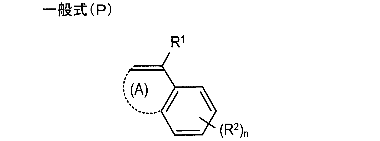
(一般式(P)において、R1は水素原子または炭素数1~4の脂肪族基を表す。R2は置換基を表す。(A)は5または6員環を形成するのに必要な原子群を表す。nは0~4の整数を表す。)

(一般式(Q)において、R26はアリール基を表し、R27およびR28はそれぞれ独立して水素原子、アルキル基、アリール基を表す。)

(一般式(S)において、R1は水素原子又は置換基を表し、R2は下記一般式(a)で表される置換基を表す。n1は0~4の整数を表し、n1が2以上のとき、複数のR1は互いに同一であっても異なっていてもよい。n2は1~5の整数を表し、n2が2以上のとき、複数のR2は互いに同一であっても異なっていてもよい。)

(一般式(a)において、Aは置換又は無置換の芳香族環を表し、R3及びR4は、それぞれ独立に、水素原子、炭素原子数1~5のアルキル基又は下記一般式(b)で表される置換基を表す。R5は、単結合又は炭素原子数1~5のアルキレン基を表し、Xは、置換又は無置換の芳香族環を表す。n3は0~10の整数を表し、n3が2以上のとき、複数のR5及びXは互いに同一であっても異なっていてもよい。)

(一般式(b)において、Xは、置換又は無置換の芳香族環を表し、R6、R7、R8、及びR9は、それぞれ独立に水素原子又は炭素原子数1~5のアルキル基を表す。n5は1~11の整数を表し、n5が2以上のとき、複数のR6、R7、R8及びXは互いに同一であっても異なっていてもよい。)
である。 1. An optical film having a hard coat layer on at least one surface of a film substrate,
The film substrate includes a hindered amine compound, a polymer containing a repeating unit derived from a monomer represented by the following general formula (P), an organic acid represented by the following general formula (Q), and the following general formula (S). Containing at least one of the compounds represented by:
The optical film, wherein the hard coat layer has a surface free energy of 30 mN / m or more after alkali treatment;
(In the general formula (P), R 1 represents a hydrogen atom or an aliphatic group having 1 to 4 carbon atoms. R 2 represents a substituent. (A) is necessary for forming a 5- or 6-membered ring. Represents an atomic group, and n represents an integer of 0 to 4.)
(In general formula (Q), R 26 represents an aryl group, and R 27 and R 28 each independently represents a hydrogen atom, an alkyl group, or an aryl group.)
(In the general formula (S), R 1 represents a hydrogen atom or a substituent, R 2 represents a substituent represented by the following general formula (a). N1 represents an integer of 0 to 4, and n1 is 2 In the above, a plurality of R 1 may be the same or different from each other, n2 represents an integer of 1 to 5, and when n2 is 2 or more, a plurality of R 2 may be the same or different from each other May be.)
(In the general formula (a), A represents a substituted or unsubstituted aromatic ring, and R 3 and R 4 are each independently a hydrogen atom, an alkyl group having 1 to 5 carbon atoms, or the following general formula (b R 5 represents a single bond or an alkylene group having 1 to 5 carbon atoms, X represents a substituted or unsubstituted aromatic ring, and n3 represents an integer of 0 to 10 And when n3 is 2 or more, the plurality of R 5 and X may be the same or different.
(In the general formula (b), X represents a substituted or unsubstituted aromatic ring, and R 6 , R 7 , R 8 , and R 9 are each independently a hydrogen atom or an alkyl having 1 to 5 carbon atoms. N5 represents an integer of 1 to 11, and when n5 is 2 or more, a plurality of R 6 , R 7 , R 8 and X may be the same or different.
It is.
前記フィルム基材は、ヒンダードアミン系化合物、下記一般式(P)で表されるモノマーに由来する繰り返し単位を含む重合体、下記一般式(Q)で表される有機酸、下記一般式(S)で表わされる化合物の少なくともいずれかを含有しており、
前記ハードコート層は、アルカリ処理後に表面自由エネルギーが30mN/m以上となることを特徴とする光学フィルム;
である。 1. An optical film having a hard coat layer on at least one surface of a film substrate,
The film substrate includes a hindered amine compound, a polymer containing a repeating unit derived from a monomer represented by the following general formula (P), an organic acid represented by the following general formula (Q), and the following general formula (S). Containing at least one of the compounds represented by:
The optical film, wherein the hard coat layer has a surface free energy of 30 mN / m or more after alkali treatment;
It is.
2.前記ハードコート層は、下記アルカリ処理条件でのアルカリ処理後に表面自由エネルギーが30mN/m以上となることを特徴とする前記1に記載の光学フィルム;
〔アルカリ処理条件〕
アルカリ溶液:2mol/L 水酸化ナトリウム溶液
処理温度:50℃
処理時間:120秒
である。 2. 2. The optical film as described in 1 above, wherein the hard coat layer has a surface free energy of 30 mN / m or more after alkali treatment under the following alkali treatment conditions;
[Alkali treatment conditions]
Alkaline solution: 2 mol / L sodium hydroxide solution Treatment temperature: 50 ° C
Processing time: 120 seconds.
3.前記ハードコート層は、前記アルカリ処理条件でのアルカリ処理後に表面自由エネルギーが40mN/m以上となることを特徴とする前記2に記載の光学フィルム。
3. 3. The optical film as described in 2 above, wherein the hard coat layer has a surface free energy of 40 mN / m or more after alkali treatment under the alkali treatment conditions.
4.前記ハードコート層が、ポリマーシランカップリング剤被覆微粒子を含有していることを特徴とする前記1から3のいずれかに記載の光学フィルム。
4. 4. The optical film as described in any one of 1 to 3 above, wherein the hard coat layer contains polymer silane coupling agent-coated fine particles.
5.前記ポリマーシランカップリング剤被覆微粒子の前記ハードコート層表面における濃度が、前記ポリマーシランカップリング剤被覆微粒子の前記ハードコート層全体における濃度よりも大きいことを特徴とする前記1から4のいずれかに記載の光学フィルム。
5. Any one of 1 to 4 above, wherein the concentration of the polymer silane coupling agent-coated fine particles on the surface of the hard coat layer is larger than the concentration of the polymer silane coupling agent-coated fine particles on the entire hard coat layer. The optical film as described.
6.前記フィルム基材は、セルロースエステルフィルムであることを特徴とする前記1から5のいずれかに記載の光学フィルム。
6. 6. The optical film as described in any one of 1 to 5, wherein the film substrate is a cellulose ester film.
7.前記1から6のいずれかに記載の光学フィルムが、偏光子の一方の面に貼り合わされていることを特徴とする偏光板。
7. 7. A polarizing plate, wherein the optical film according to any one of 1 to 6 is bonded to one surface of a polarizer.
8.前記7に記載の偏光板が、表示セルの少なくとも一方の面側に設けられていることを特徴とする画像表示装置。
8. 8. An image display device, wherein the polarizing plate according to 7 is provided on at least one surface side of the display cell.
9.前記偏光板は、前記表示セルに対して視認側に設けられているとともに、前記偏光子に対して前記光学フィルムが視認側となるように設けられており、
前記偏光板の前記光学フィルムの前記ハードコート層上に、充填剤を介して保護部が設けられていることを特徴とする前記8に記載の画像表示装置。 9. The polarizing plate is provided on the viewing side with respect to the display cell, and the optical film is provided on the viewing side with respect to the polarizer,
9. The image display device according to 8 above, wherein a protective part is provided on the hard coat layer of the optical film of the polarizing plate via a filler.
10.前記1から6のいずれかに記載の光学フィルムをアルカリ処理する工程と、
前記アルカリ処理後に、前記光学フィルムの前記セルロースエステルフィルムが前記偏光子側となるように、前記光学フィルムを前記偏光子に貼り合わせる工程とを有していることを特徴とする偏光板の製造方法。 10. A step of alkali-treating the optical film according to any one of 1 to 6;
And a step of bonding the optical film to the polarizer so that the cellulose ester film of the optical film is on the polarizer side after the alkali treatment. .
11.前記1から6のいずれかに記載の光学フィルムをアルカリ処理する工程と、
前記アルカリ処理後に、前記光学フィルムの前記セルロースエステルフィルムが前記偏光子側となるように、前記光学フィルムを前記偏光子に貼り合わせて偏光板を形成する工程と、
前記偏光板を表示セルに貼り合わせる工程と、
前記偏光板の前記光学フィルムにおける前記ハードコート層上に、光硬化型樹脂を介して保護部を形成する工程と、
活性エネルギー線を照射して前記光硬化型樹脂を硬化させることにより、充填層を形成する工程とを有していることを特徴とする画像表示装置の製造方法。 11. A step of alkali-treating the optical film according to any one of 1 to 6;
After the alkali treatment, forming the polarizing plate by bonding the optical film to the polarizer so that the cellulose ester film of the optical film is on the polarizer side;
Bonding the polarizing plate to a display cell;
Forming a protective part on the hard coat layer in the optical film of the polarizing plate via a photocurable resin;
And a step of forming a filling layer by irradiating an active energy ray to cure the photocurable resin.
本発明の光学フィルムは、偏光板や、液晶表示装置などの画像表示装置に利用可能である。
The optical film of the present invention can be used for image display devices such as polarizing plates and liquid crystal display devices.
1 画像表示装置
3 保護部
4 液晶セル(表示セル)
5 偏光板
11 偏光子
12 フィルム基材
13 ハードコート層
15 光学フィルム
31 充填層 DESCRIPTION OFSYMBOLS 1 Image display apparatus 3 Protection part 4 Liquid crystal cell (display cell)
5 Polarizingplate 11 Polarizer 12 Film substrate 13 Hard coat layer 15 Optical film 31 Filling layer
3 保護部
4 液晶セル(表示セル)
5 偏光板
11 偏光子
12 フィルム基材
13 ハードコート層
15 光学フィルム
31 充填層 DESCRIPTION OF
5 Polarizing
Claims (11)
- フィルム基材の少なくとも一方の面にハードコート層を有する光学フィルムであって、
前記フィルム基材は、ヒンダードアミン系化合物、下記一般式(P)で表されるモノマーに由来する繰り返し単位を含む重合体、下記一般式(Q)で表される有機酸、下記一般式(S)で表わされる化合物の少なくともいずれかを含有しており、
前記ハードコート層は、アルカリ処理後に表面自由エネルギーが30mN/m以上となることを特徴とする光学フィルム;


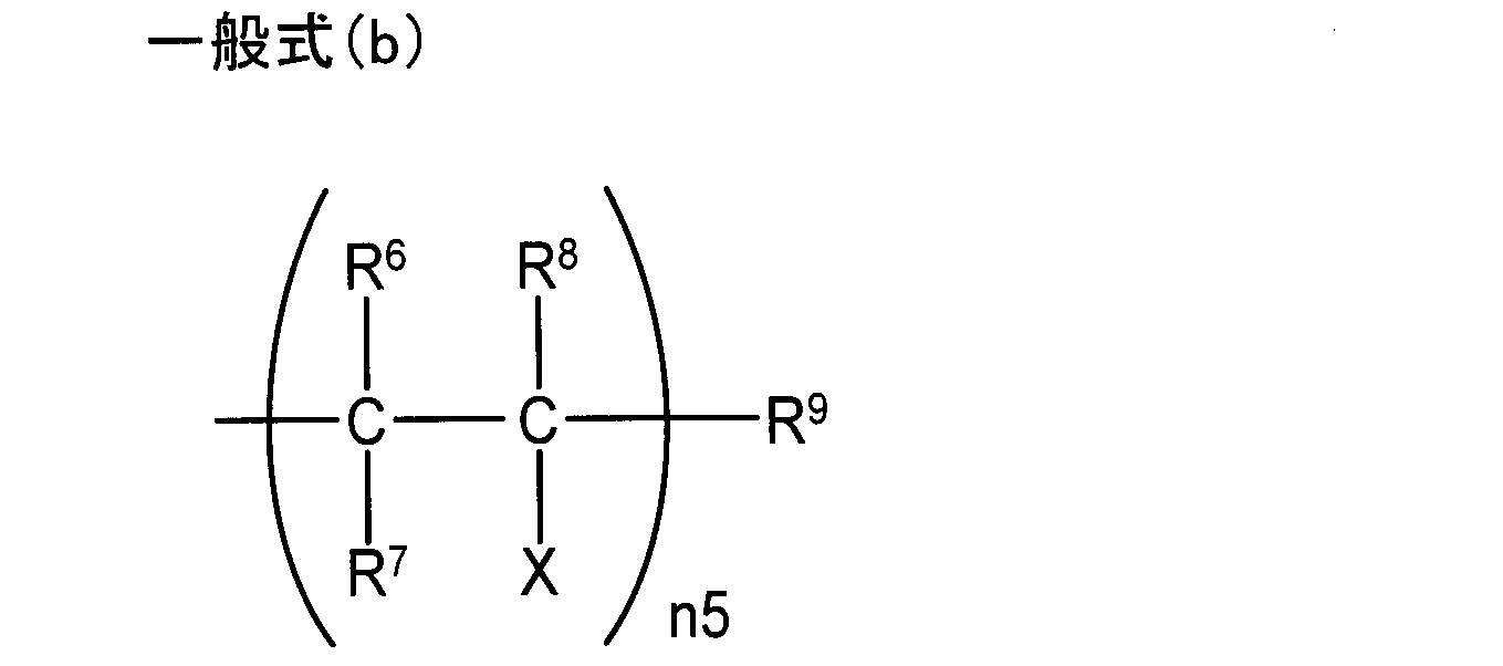
である。 An optical film having a hard coat layer on at least one surface of a film substrate,
The film substrate includes a hindered amine compound, a polymer containing a repeating unit derived from a monomer represented by the following general formula (P), an organic acid represented by the following general formula (Q), and the following general formula (S). Containing at least one of the compounds represented by:
The optical film, wherein the hard coat layer has a surface free energy of 30 mN / m or more after alkali treatment;
It is. - 前記ハードコート層は、下記アルカリ処理条件でのアルカリ処理後に表面自由エネルギーが30mN/m以上となることを特徴とする請求項1に記載の光学フィルム;
〔アルカリ処理条件〕
アルカリ溶液:2mol/L 水酸化ナトリウム溶液
処理温度:50℃
処理時間:120秒
である。 The optical film according to claim 1, wherein the hard coat layer has a surface free energy of 30 mN / m or more after alkali treatment under the following alkali treatment conditions.
[Alkali treatment conditions]
Alkaline solution: 2 mol / L sodium hydroxide solution Treatment temperature: 50 ° C
Processing time: 120 seconds. - 前記ハードコート層は、前記アルカリ処理条件でのアルカリ処理後に表面自由エネルギーが40mN/m以上となることを特徴とする請求項2に記載の光学フィルム。 3. The optical film according to claim 2, wherein the hard coat layer has a surface free energy of 40 mN / m or more after the alkali treatment under the alkali treatment conditions.
- 前記ハードコート層が、ポリマーシランカップリング剤被覆微粒子を含有していることを特徴とする請求項1から3のいずれかに記載の光学フィルム。 4. The optical film according to claim 1, wherein the hard coat layer contains fine particles coated with a polymer silane coupling agent.
- 前記ポリマーシランカップリング剤被覆微粒子の前記ハードコート層表面における濃度が、前記ポリマーシランカップリング剤被覆微粒子の前記ハードコート層全体における濃度よりも大きいことを特徴とする請求項1から4のいずれかに記載の光学フィルム。 The concentration of the polymer silane coupling agent-coated fine particles on the surface of the hard coat layer is higher than the concentration of the polymer silane coupling agent-coated fine particles on the entire hard coat layer. The optical film described in 1.
- 前記フィルム基材は、セルロースエステルフィルムであることを特徴とする請求項1から5のいずれかに記載の光学フィルム。 The optical film according to claim 1, wherein the film substrate is a cellulose ester film.
- 請求項1から6のいずれかに記載の光学フィルムが、偏光子の一方の面に貼り合わされていることを特徴とする偏光板。 A polarizing plate, wherein the optical film according to any one of claims 1 to 6 is bonded to one surface of a polarizer.
- 請求項7に記載の偏光板が、表示セルの少なくとも一方の面側に設けられていることを特徴とする画像表示装置。 An image display device, wherein the polarizing plate according to claim 7 is provided on at least one surface side of the display cell.
- 前記偏光板は、前記表示セルに対して視認側に設けられているとともに、前記偏光子に対して前記光学フィルムが視認側となるように設けられており、
前記偏光板の前記光学フィルムの前記ハードコート層上に、充填剤を介して保護部が設けられていることを特徴とする請求項8に記載の画像表示装置。 The polarizing plate is provided on the viewing side with respect to the display cell, and the optical film is provided on the viewing side with respect to the polarizer,
The image display device according to claim 8, wherein a protective part is provided on the hard coat layer of the optical film of the polarizing plate via a filler. - 請求項1から6のいずれかに記載の光学フィルムをアルカリ処理する工程と、
前記アルカリ処理後に、前記光学フィルムの前記セルロースエステルフィルムが前記偏光子側となるように、前記光学フィルムを前記偏光子に貼り合わせる工程とを有していることを特徴とする偏光板の製造方法。 A step of alkali-treating the optical film according to claim 1;
And a step of bonding the optical film to the polarizer so that the cellulose ester film of the optical film is on the polarizer side after the alkali treatment. . - 請求項1から6のいずれかに記載の光学フィルムをアルカリ処理する工程と、
前記アルカリ処理後に、前記光学フィルムの前記セルロースエステルフィルムが前記偏光子側となるように、前記光学フィルムを前記偏光子に貼り合わせて偏光板を形成する工程と、
前記偏光板を表示セルに貼り合わせる工程と、
前記偏光板の前記光学フィルムにおける前記ハードコート層上に、光硬化型樹脂を介して保護部を形成する工程と、
活性エネルギー線を照射して前記光硬化型樹脂を硬化させることにより、充填層を形成する工程とを有していることを特徴とする画像表示装置の製造方法。 A step of alkali-treating the optical film according to claim 1;
After the alkali treatment, forming the polarizing plate by bonding the optical film to the polarizer so that the cellulose ester film of the optical film is on the polarizer side;
Bonding the polarizing plate to a display cell;
Forming a protective part on the hard coat layer in the optical film of the polarizing plate via a photocurable resin;
And a step of forming a filling layer by irradiating an active energy ray to cure the photocurable resin.
Applications Claiming Priority (2)
| Application Number | Priority Date | Filing Date | Title |
|---|---|---|---|
| JP2014-076899 | 2014-04-03 | ||
| JP2014076899 | 2014-04-03 |
Publications (1)
| Publication Number | Publication Date |
|---|---|
| WO2015151795A1 true WO2015151795A1 (en) | 2015-10-08 |
Family
ID=54240127
Family Applications (1)
| Application Number | Title | Priority Date | Filing Date |
|---|---|---|---|
| PCT/JP2015/057845 WO2015151795A1 (en) | 2014-04-03 | 2015-03-17 | Optical film, polarizing plate, method for producing polarizing plate, image display device and method for manufacturing image display device |
Country Status (1)
| Country | Link |
|---|---|
| WO (1) | WO2015151795A1 (en) |
Cited By (3)
| Publication number | Priority date | Publication date | Assignee | Title |
|---|---|---|---|---|
| WO2017077740A1 (en) * | 2015-11-05 | 2017-05-11 | コニカミノルタ株式会社 | Optical film, polarization plate, and image display device |
| CN106896440A (en) * | 2016-07-05 | 2017-06-27 | 住华科技股份有限公司 | Polarizing plate |
| US20210316542A1 (en) * | 2018-08-08 | 2021-10-14 | Mitsubishi Gas Chemical Company, Inc. | Laminate for molding |
Citations (6)
| Publication number | Priority date | Publication date | Assignee | Title |
|---|---|---|---|---|
| JP2006267373A (en) * | 2005-03-23 | 2006-10-05 | Fuji Photo Film Co Ltd | Optical compensation sheet, polarizing plate, and liquid crystal display device |
| JP2012098698A (en) * | 2010-10-07 | 2012-05-24 | Fujifilm Corp | Polarizing plate protective film, polarizing plate and liquid crystal display device |
| JP2012128430A (en) * | 2004-08-09 | 2012-07-05 | Fujifilm Corp | Polymer film and optical compensation film, polarizing plate and liquid crystal display device using the same |
| JP2013112685A (en) * | 2011-11-24 | 2013-06-10 | Fujifilm Corp | Cellulose acylate film, polarizing plate protective film, polarizing plate and liquid crystal display device |
| JP2013174861A (en) * | 2012-01-25 | 2013-09-05 | Fujifilm Corp | Polarizing plate and manufacturing method thereof, and liquid crystal display device |
| JP2013174851A (en) * | 2011-04-21 | 2013-09-05 | Fujifilm Corp | Polarizing plate and liquid crystal display device |
-
2015
- 2015-03-17 WO PCT/JP2015/057845 patent/WO2015151795A1/en active Application Filing
Patent Citations (6)
| Publication number | Priority date | Publication date | Assignee | Title |
|---|---|---|---|---|
| JP2012128430A (en) * | 2004-08-09 | 2012-07-05 | Fujifilm Corp | Polymer film and optical compensation film, polarizing plate and liquid crystal display device using the same |
| JP2006267373A (en) * | 2005-03-23 | 2006-10-05 | Fuji Photo Film Co Ltd | Optical compensation sheet, polarizing plate, and liquid crystal display device |
| JP2012098698A (en) * | 2010-10-07 | 2012-05-24 | Fujifilm Corp | Polarizing plate protective film, polarizing plate and liquid crystal display device |
| JP2013174851A (en) * | 2011-04-21 | 2013-09-05 | Fujifilm Corp | Polarizing plate and liquid crystal display device |
| JP2013112685A (en) * | 2011-11-24 | 2013-06-10 | Fujifilm Corp | Cellulose acylate film, polarizing plate protective film, polarizing plate and liquid crystal display device |
| JP2013174861A (en) * | 2012-01-25 | 2013-09-05 | Fujifilm Corp | Polarizing plate and manufacturing method thereof, and liquid crystal display device |
Cited By (5)
| Publication number | Priority date | Publication date | Assignee | Title |
|---|---|---|---|---|
| WO2017077740A1 (en) * | 2015-11-05 | 2017-05-11 | コニカミノルタ株式会社 | Optical film, polarization plate, and image display device |
| JPWO2017077740A1 (en) * | 2015-11-05 | 2018-08-23 | コニカミノルタ株式会社 | Optical film, polarizing plate and image display device |
| CN106896440A (en) * | 2016-07-05 | 2017-06-27 | 住华科技股份有限公司 | Polarizing plate |
| US20210316542A1 (en) * | 2018-08-08 | 2021-10-14 | Mitsubishi Gas Chemical Company, Inc. | Laminate for molding |
| US11833792B2 (en) * | 2018-08-08 | 2023-12-05 | Mitsubishi Gas Chemical Company, Inc. | Laminate for molding |
Similar Documents
| Publication | Publication Date | Title |
|---|---|---|
| US7635506B2 (en) | Stretched cellulose ester film, hard coat film, antireflective film, and optical compensation film, and polarizing plate, and display device using them | |
| JP6048419B2 (en) | Method for producing hard coat film and method for producing polarizing plate | |
| JP5633566B2 (en) | Hard coat film, polarizing plate and liquid crystal display device | |
| WO2015098685A1 (en) | Optical film, polarizing plate and image display device | |
| JP6673363B2 (en) | Optical film, polarizing plate and image display device | |
| JP5895657B2 (en) | Manufacturing method of optical film | |
| JP2015179204A (en) | Hard coat film, polarizing plate, and image display device | |
| JP5994746B2 (en) | Liquid crystal display device with hard coat film, polarizing plate and touch panel | |
| JP6164050B2 (en) | Optical film, polarizing plate, manufacturing method thereof, and image display device | |
| WO2015151795A1 (en) | Optical film, polarizing plate, method for producing polarizing plate, image display device and method for manufacturing image display device | |
| JP5943070B2 (en) | Hard coat film, method for producing hard coat film, and touch panel display device | |
| WO2014068802A1 (en) | Optical film, method for producing optical film, polarizing plate and liquid crystal display device | |
| JP5888410B2 (en) | Method for producing hard coat film | |
| JP6048506B2 (en) | Optical film | |
| JP2015025877A (en) | Optical film, polarizing plate, and liquid crystal display device | |
| WO2016009743A1 (en) | Optical film, polarizing plate and image display device | |
| WO2016038922A1 (en) | Optical film, polarizing plate, and image display device | |
| WO2016035404A1 (en) | Optical film, polarizer, and image display device | |
| JP5104154B2 (en) | Method for producing retardation film | |
| JP2017021181A (en) | Optical film, polarizing plate, and image display device | |
| WO2016013261A1 (en) | Optical film, polarizing plate and image display device | |
| JP2017167373A (en) | Optical laminated film, polarizing plate, circularly polarizing plate, and image display device |
Legal Events
| Date | Code | Title | Description |
|---|---|---|---|
| 121 | Ep: the epo has been informed by wipo that ep was designated in this application |
Ref document number: 15772894 Country of ref document: EP Kind code of ref document: A1 |
|
| NENP | Non-entry into the national phase |
Ref country code: DE |
|
| NENP | Non-entry into the national phase |
Ref country code: JP |
|
| 122 | Ep: pct application non-entry in european phase |
Ref document number: 15772894 Country of ref document: EP Kind code of ref document: A1 |