WO2015151760A1 - Method for manufacturing interior permanent magnet inner rotor and manufacturing device for same - Google Patents
Method for manufacturing interior permanent magnet inner rotor and manufacturing device for same Download PDFInfo
- Publication number
- WO2015151760A1 WO2015151760A1 PCT/JP2015/057390 JP2015057390W WO2015151760A1 WO 2015151760 A1 WO2015151760 A1 WO 2015151760A1 JP 2015057390 W JP2015057390 W JP 2015057390W WO 2015151760 A1 WO2015151760 A1 WO 2015151760A1
- Authority
- WO
- WIPO (PCT)
- Prior art keywords
- rotor
- magnet
- rotor core
- inner rotor
- manufacturing
- Prior art date
Links
Images


Classifications
-
- H—ELECTRICITY
- H02—GENERATION; CONVERSION OR DISTRIBUTION OF ELECTRIC POWER
- H02K—DYNAMO-ELECTRIC MACHINES
- H02K15/00—Methods or apparatus specially adapted for manufacturing, assembling, maintaining or repairing of dynamo-electric machines
- H02K15/02—Methods or apparatus specially adapted for manufacturing, assembling, maintaining or repairing of dynamo-electric machines of stator or rotor bodies
- H02K15/03—Methods or apparatus specially adapted for manufacturing, assembling, maintaining or repairing of dynamo-electric machines of stator or rotor bodies having permanent magnets
-
- H—ELECTRICITY
- H01—ELECTRIC ELEMENTS
- H01F—MAGNETS; INDUCTANCES; TRANSFORMERS; SELECTION OF MATERIALS FOR THEIR MAGNETIC PROPERTIES
- H01F13/00—Apparatus or processes for magnetising or demagnetising
- H01F13/003—Methods and devices for magnetising permanent magnets
-
- H—ELECTRICITY
- H01—ELECTRIC ELEMENTS
- H01F—MAGNETS; INDUCTANCES; TRANSFORMERS; SELECTION OF MATERIALS FOR THEIR MAGNETIC PROPERTIES
- H01F41/00—Apparatus or processes specially adapted for manufacturing or assembling magnets, inductances or transformers; Apparatus or processes specially adapted for manufacturing materials characterised by their magnetic properties
- H01F41/02—Apparatus or processes specially adapted for manufacturing or assembling magnets, inductances or transformers; Apparatus or processes specially adapted for manufacturing materials characterised by their magnetic properties for manufacturing cores, coils, or magnets
- H01F41/0253—Apparatus or processes specially adapted for manufacturing or assembling magnets, inductances or transformers; Apparatus or processes specially adapted for manufacturing materials characterised by their magnetic properties for manufacturing cores, coils, or magnets for manufacturing permanent magnets
-
- H—ELECTRICITY
- H02—GENERATION; CONVERSION OR DISTRIBUTION OF ELECTRIC POWER
- H02K—DYNAMO-ELECTRIC MACHINES
- H02K15/00—Methods or apparatus specially adapted for manufacturing, assembling, maintaining or repairing of dynamo-electric machines
- H02K15/12—Impregnating, heating or drying of windings, stators, rotors or machines
-
- H—ELECTRICITY
- H02—GENERATION; CONVERSION OR DISTRIBUTION OF ELECTRIC POWER
- H02K—DYNAMO-ELECTRIC MACHINES
- H02K1/00—Details of the magnetic circuit
- H02K1/06—Details of the magnetic circuit characterised by the shape, form or construction
- H02K1/22—Rotating parts of the magnetic circuit
- H02K1/27—Rotor cores with permanent magnets
- H02K1/2706—Inner rotors
- H02K1/272—Inner rotors the magnetisation axis of the magnets being perpendicular to the rotor axis
- H02K1/274—Inner rotors the magnetisation axis of the magnets being perpendicular to the rotor axis the rotor consisting of two or more circumferentially positioned magnets
- H02K1/2753—Inner rotors the magnetisation axis of the magnets being perpendicular to the rotor axis the rotor consisting of two or more circumferentially positioned magnets the rotor consisting of magnets or groups of magnets arranged with alternating polarity
- H02K1/276—Magnets embedded in the magnetic core, e.g. interior permanent magnets [IPM]
Definitions
- the present invention relates to a method for manufacturing an inner magnet type inner rotor having an anisotropic bonded magnet as a magnetic pole, and a manufacturing apparatus therefor.
- motors including generators
- inverter control and the widespread use of rare earth magnets with high magnetic properties, attention has been focused on synchronous machines that can achieve power saving, high efficiency, high torque or high output.
- a synchronous motor is a motor having a permanent magnet in a rotor (rotor) and an armature winding (coil) in a stator (stator), and supplying alternating current (AC) to the armature winding.
- This is an AC motor that drives the rotor by generating a rotating magnetic field in the stator.
- the synchronous machine has a surface magnet type motor (Surface Permanent Magnet Synchronous Motor / simply called “SPM motor”) in which a permanent magnet is arranged on the rotor surface, and the permanent magnet is arranged in the rotor.
- IPM motor Interior-Permanent-Magnet-Synchronous-Motor / also simply called "IPM motor”
- IPM motors which can achieve high torque and power saving by reluctance torque according to magnet torque and salient pole ratio, and can improve reliability by preventing scattering of permanent magnets, are becoming mainstream.
- an internal magnet type motor rotor In conventional IPM motors, an internal magnet type motor rotor has been used in which a rare earth sintered magnet cut or polished to a predetermined dimension is inserted into a slot of a rotor core and used as a magnetic pole.
- the magnet shape that takes into account its optimized design is often a substantially arc shape or a substantially elliptical shape, and the radius of the inner and outer peripheral side surfaces is often the same. Or the magnet thickness changes in the circumferential direction.
- Such magnet processing is difficult, and the use of sintered magnets tends to increase costs.
- a defect or the like is likely to occur when inserted into the slot.
- Patent Document 1 an inner magnet-type inner rotor having a rare earth anisotropic bonded magnet formed by injecting a fluid mixture of rare earth anisotropic magnet powder and a binder resin into a slot in an orientation magnetic field as a magnetic pole (as appropriate, “IPM inner rotor” Or simply referred to as “inner rotor”) is proposed in Patent Document 1 below.
- Patent Document 1 only describes a single inner rotor.
- the inner rotor is often fixed by being shrink-fitted to a rotating shaft that is a rotating shaft of a motor or a driving shaft of each device.
- This shrink fitting is performed by heating the inner rotor to a high temperature (usually 300 to 500 ° C.).
- a high temperature usually 300 to 500 ° C.
- the permanent magnet contained in the inner rotor reduces the magnetic force (that is, causes thermal demagnetization).
- conventional permanent magnets have been designed with the expectation of thermal demagnetization, which has led to an increase in the size of permanent magnets and, in turn, IPM motors, and an increased use of rare earth elements.
- Patent Documents 2 to 3 described above relate to this.
- the inner rotor containing the permanent magnet sintered magnet or bonded magnet
- the inner rotor containing the permanent magnet is heated and shrink-fitted to the rotating shaft. Demagnetization occurs.
- the sintered magnet is loaded into the slot of the rotor core after the rotor core is shrink-fitted onto the rotating shaft.
- various manufacturing problems such as the need for rivet fixation after loading or the like may occur.
- the sintered magnet is normally loaded into the slot of the inner rotor in an unmagnetized state, and magnetized after the inner rotor is shrink-fitted onto the rotating shaft.
- This magnetization is often performed by passing an instantaneous large current (pulse current) through the stator coil after the inner rotor is disposed in the stator (this magnetization is called “built-in magnetization”).
- the stator coil may be attracted to the outer peripheral surface side of the inner rotor by a strong magnetic force generated during magnetization, and deformation or the like may occur. In order to avoid this, a separate measure is required separately (see Patent Document 4).
- the present invention has been made in view of such circumstances. Even when the rotor core is shrink-fitted and fixed to the rotating shaft, the inner magnet-type inner rotor (simply “ It is an object of the present invention to provide a manufacturing method suitable for manufacturing an inner magnet type inner rotor in which an attached rotating body is fixed to a rotating shaft by shrink fitting or the like in addition to the rotor core.
- the manufacturing method of the present invention heats a rotor core having a plurality of evenly arranged slots around a shaft hole provided in the center, and inserts the rotary shaft into the shaft hole to insert the rotary shaft into the rotary shaft.
- an inner magnet type inner rotor having an anisotropic bonded magnet obtained by solidifying the fluid mixture in the slot as a magnetic pole.
- the rotor core is baked onto the rotating shaft before filling the anisotropic bonded magnet to be the magnetic pole.
- the fluid mixture is filled into the slots of the rotor core in the orientation magnetic field using the remaining heat to form an anisotropic bonded magnet to be a magnetic pole. Therefore, the anisotropic bonded magnet according to the present invention is not exposed to a high temperature during shrink fitting and is not thermally demagnetized.
- the fluid mixture is filled into the slot of the rotor core in a heated state by the residual heat at the time of shrink fitting. For this reason, it is not necessary to heat the rotor core at the time of filling, and the fluidity of the fluid mixture in the slot can be sufficiently secured, and a dense anisotropic bonded magnet can be formed in the slot.
- the anisotropic bonded magnet that exhibits the magnetic force according to the content of the anisotropic magnet particles is formed in the slot, and the downsizing and the low cost of the inner rotor and the IPM motor can be reduced. Can be realized.
- shrink fitting is also performed by the conventional method of manufacturing an inner rotor in which a sintered magnet is loaded into a slot. Comparing this conventional manufacturing method with the manufacturing method of the present invention, the manufacturing method is similar when the permanent magnet is disposed in the slot before or after the shrink fitting. There are many. Therefore, if the manufacturing method of the present invention is used, it is easy to replace and mix with the conventional manufacturing method.
- the capital investment required to form such a mixed flow line is the preparation of a general-purpose resin filling molding machine and a magnetic field molding die that matches the product shape. In other words, it is possible to avoid a generally assumed situation in which a large investment has to be made in securing a location, building a building, newly establishing a manufacturing facility that performs all processes, and the like. As described above, according to the manufacturing method of the present invention, the capital investment can be greatly reduced even if the motor using the rare earth sintered magnet is switched to the motor using the anisotropic rare earth bonded magnet.
- the inner rotor according to the present invention is made of an anisotropic bonded magnet in which magnetic poles are filled and molded. Therefore, the shape of the slot is greater than that of a conventional inner rotor in which the magnetic pole is made of a sintered magnet.
- the magnetic pole is disposed at an accurate position without forming an air gap or the like. Also from this point of view, if the inner rotor according to the present invention is used, it is easy to promote improvement in performance, size reduction, cost reduction, etc. of the IPM motor.
- the temperature of the rotor core in the shrink fitting process or the filling process is not limited.
- the rotor core is heated to a high temperature of about 200 to 500 ° C. during the shrink-fitting process, but the temperature of the rotor core during the filling process may be about 50 to 200 ° C. or even about 100 to 150 ° C.
- the temperature at the time of shrink fitting is appropriately determined according to the tightening margin of the rotor core and the rotating shaft (torque generated between the inner rotor and the rotating shaft), etc.
- the temperature at the time of filling depends on the type of binder resin, the composition of the fluid mixture, etc. It is determined accordingly.
- the temperature of the rotor core (appropriately referred to as “core temperature”) is filled into the slot of the fluid mixture so that a dense anisotropic bonded magnet is efficiently formed in the slot. It is preferable to provide a temperature adjusting step for adjusting to a temperature suitable for the above.
- the temperature adjusting step is preferably a cooling step for cooling the rotor core at the time of shrink fitting to a temperature suitable for filling.
- a fluid mixture of anisotropic magnet particles and a binder resin is filled into a slot to which an orientation magnetic field is applied.
- each anisotropic magnet particle is in a state where its easy axis of magnetization is arranged in the direction of the orientation magnetic field, and is substantially magnetized according to the strength of the orientation magnetic field. That is, the anisotropic bonded magnet formed in the slot after the filling process is a permanent magnet that has already developed a strong magnetic force after the resin has solidified. Therefore, according to the manufacturing method of the present invention, unlike the conventional manufacturing method in which a sintered magnet is used as a magnetic pole, the magnet is inserted into the slot and then a separate magnetizing process is performed. It is not necessary to separately perform a magnetizing process on the conductive bonded magnet, and the manufacturing process can be simplified.
- the manufacturing method of the present invention does not exclude the magnetizing step. Especially when the inner rotor using anisotropic bonded magnets and the inner rotor using sintered magnets as magnetic poles are mixed in the same factory or on the same line, even in the case of the manufacturing method of the present invention. By performing the magnetizing process, it may be preferable to reduce the process difference between the two and the performance difference of the inner rotor.
- the specific heating method (in-furnace heating, high-frequency heating, etc.) and heating conditions (heating temperature, heating time, etc.) required when performing the shrink fitting process according to the present invention depend on the specifications of the inner rotor. Are appropriately selected. The same applies to the filling process.
- the type of filling molding machine used injection molding machine, transfer molding machine, vertical type, horizontal type, special purpose machine, general purpose machine, etc.
- injection conditions injection temperature, injection pressure, injection time
- the orientation magnetic field conditions orientation strength, application time, application method, etc.
- the molding apparatus can be made compact and simplified, and for example, a general-purpose injection molding machine can be easily used, and the manufacturing method of the present invention can be easily performed.
- a plurality of accommodating portions that can accommodate the rotor core, and a plurality of evenly arranged around the accommodating portion and an alignment yoke that induces an alignment magnetic field to be applied to the slots, and the alignment yoke are disposed. It is preferable that the step is performed by arranging the rotor core in an orientation mold including a permanent magnet as an orientation magnetic field source.
- the filling step according to the present invention may be a step performed in a state in which an attached rotating body other than the rotor core is fixed to the rotating shaft.
- the inner rotor can be manufactured using, for example, a general-purpose injection molding machine.
- the present invention can be grasped not only as the manufacturing method described above but also as a manufacturing apparatus suitable for carrying out the manufacturing method. That is, the present invention provides a rotor core having a plurality of evenly arranged slots around a rotating shaft and a shaft hole fitted to the rotating shaft, and a portion that is fixed to the rotating shaft and protrudes from the outer diameter of the rotor core.
- a holding mold that can hold a core assembly including an attached rotating body (for example, the attached rotating body) from one side and can support an end surface side of the rotor core on one side of the core assembly; For example, there is a rotor core).
- a housing part that can house the rotor core, a plurality of uniformly arranged around the housing part, an orientation yoke that induces an orientation magnetic field to be applied to the slot, and a circumference of the orientation yoke.
- An orientation mold having a permanent magnet as an orientation magnetic field source, and the slot from the other end face side of the rotor core accommodated in the accommodation portion and applied with the orientation magnetic field.
- a filled mold for filling a fluid mixture which is a mixture of a binder resin in a fluid state and anisotropic magnet particles, and an inner magnet-type inner core having an anisotropic bonded magnet solidified by the fluid mixture as a magnetic pole It can also be grasped as an apparatus for producing an inner magnet type inner rotor, characterized in that the rotor is obtained in a state of being fitted to the rotating shaft having the attached rotating body.
- the manufacturing apparatus of the present invention further includes a mold clamping means for clamping the orientation mold and the filling mold or the orientation mold and the holding mold.
- the alignment mold is moved from the opposite side (for example, the upper side) to the holding mold,
- the rotor core is housed in the housing portion.
- the fluid mixture is injected into the slot of the rotor core from the opposite side (for example, the upper side) of the attached rotator to form an anisotropic bonded magnet filled and molded in the orientation magnetic field in the rotor core.
- the core assembly in which the attached rotating body at least partially larger in the outer diameter direction than the inner rotor is fixed to the rotating shaft in which the inner rotor is fitted.
- anisotropic bonded magnets that serve as magnetic poles can be easily filled in the slots of the rotor core.
- the opening end surface side in the attached rotary body side (for example, lower side) of a slot will be in the obstruction
- the case where the opening end face side is indirectly supported by the holding mold means that the holding mold supports the end face side of the rotor core via an end plate or the like disposed on the axial end face of the slot. It is.
- the holding assembly may be operated to hold the core assembly by an actuator (hydraulic, pneumatic, electric, etc.) provided separately from the mold driving means (clamping means).
- a mold driving or mold clamping means may be used.
- a slider interlocking with an angular cam disposed in the orientation mold may be disposed in the holding mold, and the core assembly may be retained or the end face of the rotor core may be supported by the slider during mold clamping.
- the manufacturing apparatus and manufacturing method of this invention are closely related, one does not make the other essential.
- the manufacturing method of the present invention it is not an essential requirement to use the above-described alignment mold.
- the manufacturing apparatus of the present invention is not intended only for the rotor core that is shrink-fitted on the rotating shaft.
- the term “insertion” as used in this specification means not only the case of being shrink-fitted, but also the case of being press-fit without being shrink-fitted.
- the motor referred to in this specification includes a generator in addition to an electric motor.
- a brushless direct current (DC) motor that generates a rotating magnetic field on the stator side based on the position of the rotor detected by a detecting means such as a Hall element, a rotary encoder, or a resolver is also included.
- a detecting means such as a Hall element, a rotary encoder, or a resolver.
- x to y in this specification includes the lower limit value x and the upper limit value y.
- a range such as “ab” can be newly set as a new lower limit value or upper limit value for any numerical value included in various numerical values or numerical ranges described in this specification.
- a component related to a manufacturing method can be a component related to an object if understood as a product-by-process claim.
- ⁇ Orientation mold ⁇ It comprises a housing portion that houses the rotor core, an orientation yoke disposed around the housing portion, and a permanent magnet that is an orientation magnetic field source disposed around the orientation yoke.
- the accommodating portion has a cylindrical shape that can accommodate the rotor core, the accommodating portion may be integrated with the orientation yoke or separate.
- the plurality of orienting yokes are evenly arranged on the outer periphery of the accommodating portion, and induce an orienting magnetic field to the slots of the rotor core.
- the specific shape of the orientation yoke is not limited, the orientation die can be made compact if it is radially tapered and has a tapered radial shape whose width in the circumferential direction becomes smaller toward the outer peripheral side (larger diameter side). It is preferable because it is easy to ensure a permanent magnet volume of a predetermined value or more.
- the permanent magnet that is the orientation magnetic field source is a rare earth sintered magnet
- a strong orientation magnetic field can be applied to the slot of the rotor core while making the orientation mold compact.
- the orientation magnetic field source is an electromagnetic coil, cooling or the like is required.
- the orientation magnetic field source is a permanent magnet as in the present invention, cooling or the like is not necessary, and the orientation mold can be simplified. It becomes. Further, the temperature control of the rotor core at the time of injection can be easily performed, and a general-purpose filling molding machine can be used above all, so that it is easy to configure a production line.
- the permanent magnet is disposed with the same pole facing the opposite side surface of the orientation yoke.
- the rotor core is made of a soft magnetic material, and is usually made of a laminated body of electromagnetic steel sheets with insulation coating on both surfaces, a dust core obtained by press-molding metal particles with insulation coating, or the like.
- the soft magnetic material may be any material, but is preferably an iron-based material such as pure iron, silicon steel, or alloy steel.
- the shape and number of slots that are evenly arranged around the shaft hole provided in the center of the rotor core are not limited as long as there are at least two slots.
- the slot may be, for example, a radial type extending linearly from the center, a convex type having a convex shape on the inner peripheral side, or a multilayer type having a plurality in the radial direction.
- the anisotropic bonded magnet that is filled in the slot of the rotor core is made of anisotropic magnet particles (powder) and a binder resin.
- anisotropic magnet powder to be used is not limited, it is preferable to use a high-performance rare earth anisotropic magnet powder.
- Nd—Fe—B magnet powder, Sm—Fe—N magnet powder, Sm—Co magnet powder or the like may be used.
- the anisotropic magnet powder is not limited to a single powder, and may be a mixed powder obtained by mixing a plurality of types of powders.
- the mixed powder is not limited to those having different component compositions, and may have different particle size distributions.
- Nd—Fe—B magnet powder coarse powder and fine powder may be combined, or Nd—Fe—B magnet powder coarse powder and Sm—Fe—N magnet powder fine powder may be combined.
- anisotropic magnet powder it is possible to increase the density of the magnet particles and thereby improve the performance of the inner rotor and the IPM motor.
- the anisotropic bonded magnet according to the present invention may be a mixture of isotropic magnet particles, ferrite magnet particles, and the like as long as anisotropic magnet particles are present.
- the binder resin As the binder resin, known materials including rubber can be used. Considering the fluidity and filling properties of the fluid mixture, the binder resin is preferably a thermoplastic resin.
- the binder resin when the anisotropic bonded magnet according to the present invention is injection molded (when the filling step is an injection step), the binder resin is preferably a thermoplastic resin.
- the thermoplastic resin include polyethylene, polypropylene, polystyrene, acrylonitrile / styrene resin, acrylonitrile / butadiene / styrene resin, methacrylic resin, vinyl chloride, polyamide, polyacetal, polyethylene terephthalate, ultrahigh molecular weight polyethylene, polybutylene terephthalate, and methyl.
- thermosetting resins such as epoxy resin, unsaturated polyester resin, amino resin, phenol resin, polyamide resin, polyimide resin, polyamideimide resin, urea resin, melamine resin, urea resin, diallyl phthalate resin, and polyurethane are also used. May be. If the anisotropic bonded magnet according to the present invention is transfer molded, the binder resin may be a thermosetting resin such as an epoxy resin.
- the above-mentioned fluid mixture is less than the Curie point of the anisotropic magnet particles, such as raw material pellets made of anisotropic magnet particles and binder resin, and, for example, in the case of polyphenylene sulfide, is equal to or higher than the melting point of the binder resin. It is prepared by heating to about 280-310 ° C. This fluid mixture is injected into the slot and then solidified by being cooled to, for example, about 80 to 160 ° C. or less to become an anisotropic bonded magnet filled in the slot.
- the IPM motor according to the present invention may be used for any purpose, for example, a vehicle drive motor used in an electric vehicle, a hybrid vehicle, a railway vehicle, or the like, a motor for home appliances used in an air conditioner, a refrigerator, a washing machine, or the like. Is preferred.
- FIG. 1A A front view of a rotor assembly A which is an example using the inner rotor according to the present invention is shown in FIG. 1A.
- FIG. 1B A plan view of the rotor core 1 incorporated in the rotor assembly A is shown in FIG. 1B.
- FIG. 1B A plan view of the rotor core 1 incorporated in the rotor assembly A is shown in FIG. 1B.
- FIG. 1B For convenience, the arrow direction shown in FIG.
- the rotor assembly A includes an inner rotor 10, a rotating shaft 20, and a load body 30 (attached rotating body).
- the rotor core 1 constituting the inner rotor 10 has a substantially cylindrical shape, a shaft hole 11 having a key groove 111 provided in the center, and a substantially uniform arrangement around the shaft hole 11.
- Eight U-shaped slots 121 to 128 (collectively referred to as “slot 12”) and four rivet holes 131 to 134 that are equally disposed between the shaft hole 11 and the slot 12 (collectively these).
- slot 12 Eight U-shaped slots 121 to 128
- rivet holes 131 to 134 that are equally disposed between the shaft hole 11 and the slot 12 (collectively these).
- rivet hole 13 The rotor core 1 is formed by laminating silicon steel plates punched into the shape shown in FIG. 1B.
- End plates 41 and 42 are fixed to the upper end surface and the lower end surface of the rotor core 1.
- the upper and lower openings of the slot 12 of the inner rotor 10 are closed by the end plates 41 and 42.
- the end plate 41 is formed with eight small filling holes 4111 to 4118 (collectively referred to as “filling holes 411” / see FIG. 5) communicating with the slots 121 to 128, respectively.
- filling holes 411 are formed with eight small filling holes 4111 to 4118 (collectively referred to as “filling holes 411” / see FIG. 5) communicating with the slots 121 to 128, respectively.
- balance weights 43 and 44 are fixed, respectively.
- the rotor core 1, the end plates 41 and 42, and the balance weights 43 and 44 are fastened together by four rivets 451 to 454 that pass through the rivet hole 13 (collectively referred to as “rivets 45”).
- rare earth anisotropic bonded magnets b1 to b8 (collectively referred to as “rare earth anisotropic bonded magnet b”) formed by injection molding through the filling holes 411 are formed.
- the inner rotor 10 not only the rotor core 1 and each rare earth anisotropic bonded magnet b but also the end plates 41 and 42 and the balance weights 43 and 44 fixed to the rotor core 1 by the rivets 45 described above are referred to as the inner rotor 10.
- the load body 30 is a drive unit that drives the compressor for an air conditioner, and includes flanges 31 and 32 and a crank 33 interposed therebetween. These have an outer shape protruding in the radial direction from the inner rotor 10.
- the load body 30 is press-fitted into the rotating shaft 20 (press-fitting process), and the inner rotor 10 is shrink-fitted and fixed to the rotating shaft 20 (shrink-fitting process).
- the inner rotor 10 is fixed to the rotating shaft 20 by inserting the rotating shaft 20 into the shaft hole 11 when the rotor core 1 is heated to about 200 to 500 ° C., and the rotor assembly A (rare earth anisotropic bonded magnet). before filling b).
- the fluid mixture is filled into the slots 12 from the filling holes 411 (injection process), thereby forming a magnetic pole made of the rare earth anisotropic bonded magnet b in the inner rotor 10.
- transfer molding can be performed instead of injection molding.
- the thermoplastic resin used in the injection molding is solidified by cooling, but the thermosetting resin used in the transfer molding is solidified by heating in the mold or a curing process (curing heat treatment) after the transfer molding.
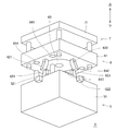
- the rare earth anisotropic bonded magnet b can be molded by setting a molding die D shown in FIG. 2 in a general-purpose vertical injection molding machine. For convenience, the arrow direction shown in FIG.
- the molding mold D has a three-layer structure of a holding mold 5, an orientation mold 6, and an injection mold 7. As shown in FIGS. 2 and 3, the holding mold 5 includes a base 51 and four slide cores 521 to 524 that slide forward and backward from the center of each side of the base 51 to the center. Core 52 ”) and guide pins 531 to 534 (collectively referred to as“ guide pins 53 ”) protruding vertically from the upper surface side of the base 51.
- the slide core 52 has a substantially prismatic shape, and fitting holes 5211 to 5241 are formed outside the center of each slide core 52. Further, at the center side of each slide core 52 (center side of the holding mold 5), the rotary shaft 20 is surrounded by the inner rotor 10 of the rotor assembly A and the load body 30, and the end plate 42 is disposed below. Support portions 5212 to 5242 are formed to be supported from the bottom. Further, a space (not shown) for accommodating the load body 30 fixed to the rotating shaft 20 is provided below the center of the base 51, and a shaft hole (not shown) into which the lower end portion of the rotating shaft 20 is inserted is also provided. Is formed.
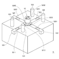
- the orientation mold 6 includes a base 61 and four angular cams 621 to 624 projecting obliquely outward from the lower surface side of the base 61 (collectively referred to as “angular cam 62”). ), And guide holes 641 to 644 that fit into the orientation magnetic field body 63 installed in the center of the base 61 and guide pins 531 to 534 provided on the upper surface side of the base 51 of the holding mold 5 (theses). Are collectively referred to as “guide holes 64”).
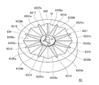
- the alignment magnetic field 63 has eight alignment yokes 6311 to 6318 that project radially and elongate on the outer peripheral side (collectively referred to as “orientation yoke 631”), and each alignment yoke 631 is bridged in an arc shape, and is formed at the center.
- a cylindrical housing portion 632 having a smoothly continuous inner peripheral surface, and 16 permanent magnets 6331a to 6331a serving as orientation magnetic field sources arranged with the same poles facing each other on the opposite side surfaces in the circumferential direction of each orientation yoke 631.
- Each permanent magnet 633a, 633b is made of a rare earth sintered magnet.
- orientation yoke 631 and the permanent magnets 633a and 633b are disposed in contact with the south pole on the circumferential side surface of the orientation yoke 6311, and a permanent magnet 6332a and a permanent magnet 6332b are disposed on the circumferential side surface of the adjacent orientation yoke 6312.
- a permanent magnet 6332a and a permanent magnet 6332b are disposed on the circumferential side surface of the adjacent orientation yoke 6312.
- an alignment magnetic field that is opposite between adjacent ones is efficiently applied to each slot 12 of the rotor core 1 accommodated in the accommodating portion 632.
- a flow path (not shown) serving as a passage for a fluid mixture of rare earth anisotropic magnet powder and binder resin (thermoplastic resin) is formed inside the center of the base 71. It becomes.
- the flow path includes a spool 721, eight runners 7221-7228 connected to the spool 721 (collectively referred to as “runners 722”), and thin pin gates 7231-7238 connected to the runners 722. These are collectively referred to as “pin gate 723”).
- the tip of each pin gate 723 is connected to each filling hole 411 of the end plate 41, and each slot 12 is filled with the fluid mixture through each pin gate 723.
- the slide core 52 is moved to the center of the holding mold 5, and at the same time, the orientation mold is lowered toward the holding mold 5.
- the load body 30 is pulled to the orientation mold by a magnetic attractive force.
- the upper end surface of the load body 30 comes into contact with the lower end surface (inner circumference) of the support portion 521 and surrounds the rotary shaft 20.
- the rotor assembly A is in a state in which the axial movement is temporarily restrained. As a result, it is possible to prevent the rotor assembly A from being unexpectedly magnetized to the alignment magnetic field 63 when the alignment mold 6 is lowered toward the holding mold 5.
- the orientation mold 6 When the orientation mold 6 is lowered from the rotor core 1 side with respect to the rotor assembly A in this state, the guide pins 53 of the holding mold 5 and the guide holes 64 of the orientation mold 6 are fitted and held. The upper surface of the mold 5 and the lower surface of the alignment mold 6 are close to each other. At this time, the respective angular cams 62 are fitted into the fitting holes 5211 to 5241 of the respective slide cores 52, and the slide cores 52 move toward the center of the holding mold 5 as the angular cams 62 are lowered.
- each slide core 52 the support portions 5222 to 5242 of each slide core 52 are located between the inner rotor 10 and the load body 30, surround the outer periphery of the rotary shaft 20 between them, and lower the end plate 42 of the inner rotor 10. Support from the side.
- the load body 30 connected via the inner rotor 10 and the rotating shaft 20 is also held.
- the rotor assembly A is securely held by the holding mold 5, and the rotor core 1 is housed in the housing portion 632 of the orientation magnetic field body 63.
- the orienting magnetic body 63 uses permanent magnets 633a and 633b (collectively referred to as “permanent magnet 633”) as an orienting magnetic field source, the rotor core 1 is accommodated in the accommodating portion 632 in each slot 12 in the stage. Is in a state where a predetermined orientation magnetic field is applied.
- the injection mold 7 is also lowered in conjunction with the alignment mold 6 so that the lower surface of the injection mold 7 and the upper surface of the alignment mold 6 are in close contact with each other.
- the tip of each pin gate 723 is connected to each filling hole 411 of the end plate 41.
- each slot 12 of the rotor core 1 is completely closed by the end plate 42, and the end plate 42 is supported on the upper end side of the support portions 5212 to 5242 of the slide core 52. As a result, the clamping force is supported.
- this rare earth anisotropic bonded magnet b is a permanent magnet that is injection-molded with a strong orientation magnetic field applied, it has already exerted a strong magnetic force without being magnetized.
- the rotor assembly A in which the magnetized rare earth anisotropic bonded magnet b becomes a magnetic pole is obtained.
- An IPM motor can be obtained by incorporating this rotor assembly A into the stator.
- the alignment mold 6 and the injection mold 7 were moved using a driving means (clamping means) such as a hydraulic actuator provided in a general-purpose vertical injection molding machine.
Landscapes
- Engineering & Computer Science (AREA)
- Power Engineering (AREA)
- Manufacturing & Machinery (AREA)
- Permanent Field Magnets Of Synchronous Machinery (AREA)
- Manufacture Of Motors, Generators (AREA)
Abstract
Provided is a manufacturing method capable of obtaining an interior permanent magnet inner rotor, in which shrink-fitting the interior permanent magnet inner rotor to a rotating shaft does not cause thermal demagnetization.
The manufacturing method of the present invention is characterized by comprising: a shrink fitting step of heating a rotor core (1) having slots, fitting a rotating shaft (20) into a shaft hole, and shrink-fitting the rotor core; and a filling step of, in an oriented magnetic field, filling a fluidized mixture into the slots of the rotor core that retains residual heat after the shrink fitting step, said fluidized mixture being a mixture of a binder resin heated to a fluidized state and anisotropic magnetic particles. This makes it possible to obtain, in similar manufacturing processes, an inner rotor (10) using anisotropic bond magnets obtained by solidifying the fluidized mixture in the slots as magnetic poles and an inner rotor using conventional sintered magnets as magnetic poles. As a result, it is also facilitated to produce both inner rotors concurrently and in parallel (mixed flow production) in an already existing IPM motor manufacturing line.
Description
本発明は、異方性ボンド磁石を磁極とする内包磁石型インナーロータの製造方法およびその製造装置に関する。
The present invention relates to a method for manufacturing an inner magnet type inner rotor having an anisotropic bonded magnet as a magnetic pole, and a manufacturing apparatus therefor.
電動機(発電機を含めて単に「モータ」という。)には種々のタイプがある。最近ではインバータ制御の発達と高磁気特性の希土類磁石の普及に伴い、省電力、高効率、高トルクまたは高出力が望める同期機が着目されている。
There are various types of motors (simply called “motors” including generators). Recently, with the development of inverter control and the widespread use of rare earth magnets with high magnetic properties, attention has been focused on synchronous machines that can achieve power saving, high efficiency, high torque or high output.
同期機(Synchronous Motor)は、回転子(ロータ)に永久磁石を、固定子(ステータ)に電機子巻線(コイル)を備えるモータであり、電機子巻線に交流(AC)を供給して固定子に回転磁界を生じさせることにより回転子を駆動するACモータである。同期機には、永久磁石が回転子の表面に配設された表面磁石型モータ(Surface Permanent Magnet Synchronous Motor/単に「SPMモータ」ともいう。)と、その永久磁石が回転子の内部に配設された内包(埋込)磁石型モータ(Interior Permanent Magnet Synchronous Motor/単に「IPMモータ」ともいう。)とがある。現在では、マグネットトルクと突極比に応じたリラクタンストルクにより高トルク化や省電力化を図れ、また永久磁石の飛散防止により信頼性の向上も図れるIPMモータが主流となりつつある。
A synchronous motor is a motor having a permanent magnet in a rotor (rotor) and an armature winding (coil) in a stator (stator), and supplying alternating current (AC) to the armature winding. This is an AC motor that drives the rotor by generating a rotating magnetic field in the stator. The synchronous machine has a surface magnet type motor (Surface Permanent Magnet Synchronous Motor / simply called “SPM motor”) in which a permanent magnet is arranged on the rotor surface, and the permanent magnet is arranged in the rotor. There is a built-in (embedded) magnet type motor (Interior-Permanent-Magnet-Synchronous-Motor / also simply called "IPM motor"). Currently, IPM motors, which can achieve high torque and power saving by reluctance torque according to magnet torque and salient pole ratio, and can improve reliability by preventing scattering of permanent magnets, are becoming mainstream.
これまでのIPMモータでは、所定の寸法に切削や研磨等された希土類焼結磁石をロータコアのスロット内へ挿入して磁極とした内包磁石型モータ用ロータが用いられてきた。しかし、焼結磁石は形状自由度が小さいにも拘わらず、その最適化設計を考慮した磁石形状は、略円弧形状あるいは略楕円形状となることが多く、しかもその内周側面と外周側面の半径が異なったり、磁石厚さが周方向で変化したりする。このような磁石加工は困難であり、焼結磁石の利用は高コスト化し易い。またスロットへ挿入する際に欠損等が生じ易い。このため、多くのIPMモータにおいては、やむをえず板形状のような単純形状の焼結磁石が用いられてきた。そこで、希土類異方性磁石粉末とバインダ樹脂の流動混合物を配向磁場中のスロット内へ射出して成形した希土類異方性ボンド磁石を磁極とする内包磁石型インナーロータ(適宜、「IPMインナーロータ」または単に「インナーロータ」という。)が下記の特許文献1で提案されている。但し、特許文献1にはインナーロータ単体に関する記載しかない。
In conventional IPM motors, an internal magnet type motor rotor has been used in which a rare earth sintered magnet cut or polished to a predetermined dimension is inserted into a slot of a rotor core and used as a magnetic pole. However, despite the small degree of freedom in shape of sintered magnets, the magnet shape that takes into account its optimized design is often a substantially arc shape or a substantially elliptical shape, and the radius of the inner and outer peripheral side surfaces is often the same. Or the magnet thickness changes in the circumferential direction. Such magnet processing is difficult, and the use of sintered magnets tends to increase costs. In addition, a defect or the like is likely to occur when inserted into the slot. For this reason, in many IPM motors, a sintered magnet having a simple shape like a plate shape has been used. Therefore, an inner magnet-type inner rotor having a rare earth anisotropic bonded magnet formed by injecting a fluid mixture of rare earth anisotropic magnet powder and a binder resin into a slot in an orientation magnetic field as a magnetic pole (as appropriate, “IPM inner rotor” Or simply referred to as “inner rotor”) is proposed in Patent Document 1 below. However, Patent Document 1 only describes a single inner rotor.
ところで、インナーロータは、モータの回転軸または各機器の駆動軸となる回転シャフトに焼嵌めされて固定されることが多い。この焼嵌めは、インナーロータを高温(通常は300~500℃)に加熱してなされる。この加熱の影響を受けて、インナーロータに内包されている永久磁石は磁力を低下させる(つまり熱減磁を生じる)。このため、これまでの永久磁石はその熱減磁を見込んで設計されており、その分、永久磁石ひいてはIPMモータの大型化、稀少な希土類元素の使用量増加を招来していた。
By the way, the inner rotor is often fixed by being shrink-fitted to a rotating shaft that is a rotating shaft of a motor or a driving shaft of each device. This shrink fitting is performed by heating the inner rotor to a high temperature (usually 300 to 500 ° C.). Under the influence of this heating, the permanent magnet contained in the inner rotor reduces the magnetic force (that is, causes thermal demagnetization). For this reason, conventional permanent magnets have been designed with the expectation of thermal demagnetization, which has led to an increase in the size of permanent magnets and, in turn, IPM motors, and an increased use of rare earth elements.
このような観点から、インナーロータの回転シャフトへの焼嵌め時に生じる永久磁石の熱減磁を抑制する提案が多くなされている。例えばこれに関連した記載が上記の特許文献2~3にある。しかし、いずれの場合でも、永久磁石(焼結磁石またはボンド磁石)を内包したインナーロータを加熱して回転シャフトへ焼嵌めをしていることに変わりなく、多かれ少なかれ、焼嵌め時に永久磁石の熱減磁が生じる。
From this point of view, many proposals have been made to suppress the thermal demagnetization of the permanent magnet that occurs when the inner rotor is fitted to the rotating shaft. For example, Patent Documents 2 to 3 described above relate to this. However, in any case, the inner rotor containing the permanent magnet (sintered magnet or bonded magnet) is heated and shrink-fitted to the rotating shaft. Demagnetization occurs.
ここで、回転シャフトへロータコアを焼嵌めした後に、焼結磁石をロータコアのスロットへ装填等することも考えられる。しかし、このような製造工程では、装填等後にリベット固定が必要になるなど、種々の製造上の問題を生じることが考えられる。
Here, it is also conceivable that the sintered magnet is loaded into the slot of the rotor core after the rotor core is shrink-fitted onto the rotating shaft. However, in such a manufacturing process, various manufacturing problems such as the need for rivet fixation after loading or the like may occur.
また、焼結磁石は、作業性や取扱性等の観点から、通常、未着磁状態でインナーロータのスロットへ装填され、そのインナーロータを回転シャフトへ焼嵌めした後に着磁がなされる。この着磁は、インナーロータをステータ内に配設した後に、ステータコイルに瞬間的な大電流(パルス電流)を流すことによってなされることが多い(このような着磁を「組込み着磁」という。)。しかし、組込み着磁を行うと、着磁の際に発生する強力な磁力により、ステータコイルがインナーロータの外周面側へ吸引されて変形等を生じ得る。これを回避するには、別途、そのためだけの対策が必要となる(特許文献4参照)。
Also, from the viewpoint of workability, handling, etc., the sintered magnet is normally loaded into the slot of the inner rotor in an unmagnetized state, and magnetized after the inner rotor is shrink-fitted onto the rotating shaft. This magnetization is often performed by passing an instantaneous large current (pulse current) through the stator coil after the inner rotor is disposed in the stator (this magnetization is called “built-in magnetization”). .) However, when built-in magnetization is performed, the stator coil may be attracted to the outer peripheral surface side of the inner rotor by a strong magnetic force generated during magnetization, and deformation or the like may occur. In order to avoid this, a separate measure is required separately (see Patent Document 4).
本発明はこのような事情に鑑みて為されたものであり、ロータコアを回転シャフトへ焼嵌めして固定する場合でも、内包する永久磁石に熱減磁を生じさせない内包磁石型インナーロータ(単に「インナーロータ」という。)の製造方法と、ロータコアの他に付属回転体が回転シャフトに焼嵌め等により固定された内包磁石型インナーロータの製造に適した製造装置を提供することを目的とする。
The present invention has been made in view of such circumstances. Even when the rotor core is shrink-fitted and fixed to the rotating shaft, the inner magnet-type inner rotor (simply “ It is an object of the present invention to provide a manufacturing method suitable for manufacturing an inner magnet type inner rotor in which an attached rotating body is fixed to a rotating shaft by shrink fitting or the like in addition to the rotor core.
本発明者はこの課題を解決すべく鋭意研究し、試行錯誤を重ねた結果、ロータコアを回転シャフトへ焼嵌めした後に、そのスロット中に磁極となる異方性ボンド磁石を充填成形することを思いついた。この着想を具現化し発展させることにより、以降に述べる本発明を完成するに至った。
As a result of extensive research and trial and error, the present inventor has come up with the idea that after the core of the rotor is shrink-fitted onto the rotating shaft, an anisotropic bonded magnet serving as a magnetic pole is filled in the slot. It was. By realizing and developing this idea, the present invention described below has been completed.
《内包磁石型インナーロータの製造方法》
(1)本発明の製造方法は、中央に設けられたシャフト穴の周囲に複数均等に配設されたスロットを有するロータコアを加熱し、該シャフト穴へ回転シャフトを嵌挿して該回転シャフトに該ロータコアを焼嵌めする焼嵌工程と、該焼嵌工程後の余熱状態にある該ロータコアのスロットへ加熱されて流動状態にあるバインダ樹脂と異方性磁石粒子との混合物である流動混合物を配向磁場中で充填する充填工程とを備え、該スロット内の流動混合物を固化させた異方性ボンド磁石を磁極とする内包磁石型インナーロータが得られることを特徴とする。 《Method for manufacturing inner magnet type inner rotor》
(1) The manufacturing method of the present invention heats a rotor core having a plurality of evenly arranged slots around a shaft hole provided in the center, and inserts the rotary shaft into the shaft hole to insert the rotary shaft into the rotary shaft. A shrink fitting process for shrink fitting the rotor core, and a fluid mixture, which is a mixture of the binder resin and anisotropic magnet particles in a fluid state heated to the slot of the rotor core in a preheated state after the shrink fitting process, is applied to the orientation magnetic field. And an inner magnet type inner rotor having an anisotropic bonded magnet obtained by solidifying the fluid mixture in the slot as a magnetic pole.
(2)本発明の内包磁石型インナーロータ(適宜、「インナーロータ」または単に「ロータ」という。)の製造方法では、磁極となる異方性ボンド磁石の充填成形前にロータコアを回転シャフトへ焼嵌めした後に、その余熱を利用しつつロータコアのスロットへ流動混合物を配向磁場中で充填して、磁極となる異方性ボンド磁石を成形している。従って、本発明に係る異方性ボンド磁石は焼嵌め時に高温に曝されることがなく、熱減磁することがない。また、本発明の製造方法では、焼嵌め時の余熱により加熱状態にあるロータコアのスロットへ流動混合物が充填される。このため、充填時にロータコアをわざわざ加熱するまでもなく、スロット内における流動混合物の流動性を十分に確保でき、スロット内に緻密な異方性ボンド磁石を成形することができる。
(2) In the manufacturing method of the inner magnet type inner rotor of the present invention (appropriately referred to as “inner rotor” or simply “rotor”), the rotor core is baked onto the rotating shaft before filling the anisotropic bonded magnet to be the magnetic pole. After the fitting, the fluid mixture is filled into the slots of the rotor core in the orientation magnetic field using the remaining heat to form an anisotropic bonded magnet to be a magnetic pole. Therefore, the anisotropic bonded magnet according to the present invention is not exposed to a high temperature during shrink fitting and is not thermally demagnetized. In the production method of the present invention, the fluid mixture is filled into the slot of the rotor core in a heated state by the residual heat at the time of shrink fitting. For this reason, it is not necessary to heat the rotor core at the time of filling, and the fluidity of the fluid mixture in the slot can be sufficiently secured, and a dense anisotropic bonded magnet can be formed in the slot.
このように本発明の製造方法によれば、異方性磁石粒子の含有量に応じた磁力を発揮する異方性ボンド磁石がスロット内に形成され、インナーロータひいてはIPMモータの小型化や低コスト化を図れる。
As described above, according to the manufacturing method of the present invention, the anisotropic bonded magnet that exhibits the magnetic force according to the content of the anisotropic magnet particles is formed in the slot, and the downsizing and the low cost of the inner rotor and the IPM motor can be reduced. Can be realized.
ちなみに、焼結磁石をスロットへ装填する従来のインナーロータの製造方法でも焼嵌めはなされる。この従来の製造方法と本発明の製造方法を比較すると、スロット内に永久磁石が配設されるときが、その焼嵌め前か焼嵌め後かで異なるものの、両製造方法は類似している工程も多い。従って本発明の製造方法を用いれば、従来の製造方法との置換や混在も行い易い。
Incidentally, shrink fitting is also performed by the conventional method of manufacturing an inner rotor in which a sintered magnet is loaded into a slot. Comparing this conventional manufacturing method with the manufacturing method of the present invention, the manufacturing method is similar when the permanent magnet is disposed in the slot before or after the shrink fitting. There are many. Therefore, if the manufacturing method of the present invention is used, it is easy to replace and mix with the conventional manufacturing method.
この点を具体例を挙げて詳細に説明すると、次の通りである。焼結磁石を用いたモータの製造工程を異方性希土類ボンド磁石を用いたモータの製造工程へ変更した場合を考えると、基本的に相違する点は、磁石の材質および形状およびロータにおけるスロットの形状、スロットへの磁石の挿入方法およびそのタイミングに留まる。その他の点、例えば、ステータや制御回路等も両モータ間で相違がなく、両モータの組付けや加工等も既設の設備で同様に行うことができる。そして焼結磁石を用いたモータを異方性ボンド磁石を用いたモータに変更することにより、上述したように工程省略と省エネルギー化等を図れる。
This point will be described in detail with a specific example as follows. Considering the case of changing the motor manufacturing process using sintered magnets to the motor manufacturing process using anisotropic rare earth bonded magnets, the fundamental differences are the magnet material and shape, and the slot of the rotor. The shape, the method of inserting the magnet into the slot and the timing remain. Other points, for example, the stator and the control circuit are not different between the two motors, and the assembly and processing of the two motors can be performed in the same manner with the existing equipment. Then, by changing the motor using the sintered magnet to the motor using the anisotropic bonded magnet, the process can be omitted and the energy can be saved as described above.
そこで、例えば、現行の焼結磁石を用いたモータの製造ラインの近接スペースに、異方性希土類ボンド磁石を用いたモータの製造スペースを設けて、焼結磁石を用いたモータを製造する場合と同様に、部品等を前工程から受け入れて、加工し、後工程へ供給するゾーンを設ける。これにより、既設の焼結磁石を用いたモータラインと異方性希土類ボンド磁石を用いたモータラインを混在させることが可能となる。
Therefore, for example, in the case of manufacturing a motor using a sintered magnet by providing a manufacturing space for a motor using an anisotropic rare earth bonded magnet in the adjacent space of a motor manufacturing line using a current sintered magnet Similarly, a zone for receiving parts from the previous process, processing them, and supplying them to the subsequent process is provided. Thereby, it is possible to mix a motor line using an existing sintered magnet and a motor line using an anisotropic rare earth bonded magnet.
このような混流ラインの形成に必要な設備投資は、汎用の樹脂充填成形機と、製品形状に合せた磁場成形金型の準備程度である。つまり、立地場所の確保、建屋の建設、全工程を行う製造設備の新設等に大きな投資をしなければならないという、一般的に想定される状況は回避され得る。このように本発明の製造方法によれば、希土類焼結磁石を用いたモータを異方性希土類ボンド磁石を用いたモータへ切り替えても、設備投資は大幅に削減され得る。
The capital investment required to form such a mixed flow line is the preparation of a general-purpose resin filling molding machine and a magnetic field molding die that matches the product shape. In other words, it is possible to avoid a generally assumed situation in which a large investment has to be made in securing a location, building a building, newly establishing a manufacturing facility that performs all processes, and the like. As described above, according to the manufacturing method of the present invention, the capital investment can be greatly reduced even if the motor using the rare earth sintered magnet is switched to the motor using the anisotropic rare earth bonded magnet.
なお、本発明に係るインナーロータは、磁極が充填成形された異方性ボンド磁石からなるため、磁極が焼結磁石からなる従来のインナーロータよりも、スロットの形状自由度が大きく、スロット内にエアギャップ等が形成されることなく、正確な位置に磁極が配設される。この観点からも、本発明に係るインナーロータを用いれば、IPMモータの高性能化、小型化、低コスト化等の促進が図り易い。
The inner rotor according to the present invention is made of an anisotropic bonded magnet in which magnetic poles are filled and molded. Therefore, the shape of the slot is greater than that of a conventional inner rotor in which the magnetic pole is made of a sintered magnet. The magnetic pole is disposed at an accurate position without forming an air gap or the like. Also from this point of view, if the inner rotor according to the present invention is used, it is easy to promote improvement in performance, size reduction, cost reduction, etc. of the IPM motor.
(3)本発明の製造方法では、焼嵌工程または充填工程におけるロータコアの温度は問わない。通常、ロータコアは焼嵌工程時に200~500℃程度まで高温加熱されるが、充填工程時のロータコアの温度は50~200℃さらには100~150℃程度でよい。焼嵌め時の温度は、ロータコアと回転シャフトの締め代(インナーロータと回転シャフトの間に生じるトルク)等に応じて適宜決定され、充填時の温度はバインダ樹脂の種類、流動混合物の組成等に応じて適宜決定される。そこで本発明に係る充填工程は、緻密な異方性ボンド磁石がスロット内に効率的に形成されるように、ロータコアの温度(適宜、「コア温度」という。)を流動混合物のスロットへの充填に適した温度に調節する温度調節工程を備えると好適である。通常は、焼嵌め時の温度が充填時の温度よりもかなり高いため、温度調節工程は焼嵌め時のロータコアを充填に適切な温度まで冷却する冷却工程であると好ましい。
(3) In the manufacturing method of the present invention, the temperature of the rotor core in the shrink fitting process or the filling process is not limited. Usually, the rotor core is heated to a high temperature of about 200 to 500 ° C. during the shrink-fitting process, but the temperature of the rotor core during the filling process may be about 50 to 200 ° C. or even about 100 to 150 ° C. The temperature at the time of shrink fitting is appropriately determined according to the tightening margin of the rotor core and the rotating shaft (torque generated between the inner rotor and the rotating shaft), etc. The temperature at the time of filling depends on the type of binder resin, the composition of the fluid mixture, etc. It is determined accordingly. Therefore, in the filling process according to the present invention, the temperature of the rotor core (appropriately referred to as “core temperature”) is filled into the slot of the fluid mixture so that a dense anisotropic bonded magnet is efficiently formed in the slot. It is preferable to provide a temperature adjusting step for adjusting to a temperature suitable for the above. Usually, since the temperature at the time of shrink fitting is considerably higher than the temperature at the time of filling, the temperature adjusting step is preferably a cooling step for cooling the rotor core at the time of shrink fitting to a temperature suitable for filling.
本発明に係る充填工程では、配向磁場が印加されたスロットへ、異方性磁石粒子とバインダ樹脂の流動混合物が充填される。この際、各異方性磁石粒子は、その磁化容易軸が配向磁場方向に配列した状態になると共に、配向磁場の強さに応じた着磁が実質的になされた状態となる。つまり、充填工程後にスロット内に形成された異方性ボンド磁石は、樹脂が固化した後は、既に強力な磁力を発現した永久磁石となっている。このため本発明の製造方法によれば、焼結磁石を磁極とする従来の製造方法のように、スロットに磁石を挿入し、その後別途着磁工程を行う場合とは異なり、充填工程後に異方性ボンド磁石に対して着磁工程を別途行う必要がなく、製造工程の簡素化が図られる。
In the filling step according to the present invention, a fluid mixture of anisotropic magnet particles and a binder resin is filled into a slot to which an orientation magnetic field is applied. At this time, each anisotropic magnet particle is in a state where its easy axis of magnetization is arranged in the direction of the orientation magnetic field, and is substantially magnetized according to the strength of the orientation magnetic field. That is, the anisotropic bonded magnet formed in the slot after the filling process is a permanent magnet that has already developed a strong magnetic force after the resin has solidified. Therefore, according to the manufacturing method of the present invention, unlike the conventional manufacturing method in which a sintered magnet is used as a magnetic pole, the magnet is inserted into the slot and then a separate magnetizing process is performed. It is not necessary to separately perform a magnetizing process on the conductive bonded magnet, and the manufacturing process can be simplified.
但し、本発明の製造方法は着磁工程を排除するものではない。特に、異方性ボンド磁石を磁極とするインナーロータと焼結磁石を磁極とするインナーロータが、同一工場内さらには同一ライン上で混在しているような場合、本発明の製造方法の場合でも着磁工程を行うことにより両者間の工程差やインナーロータの性能差を少なくすることができて好ましいこともある。
However, the manufacturing method of the present invention does not exclude the magnetizing step. Especially when the inner rotor using anisotropic bonded magnets and the inner rotor using sintered magnets as magnetic poles are mixed in the same factory or on the same line, even in the case of the manufacturing method of the present invention. By performing the magnetizing process, it may be preferable to reduce the process difference between the two and the performance difference of the inner rotor.
(4)本発明に係る焼嵌工程を行う際に必要となる具体的な加熱方法(炉内加熱、高周波加熱等)、加熱条件(加熱温度、加熱時間等)は、インナーロータの仕様に応じて適宜選択される。また充填工程についても同様であり、用いる充填成形機の種類(射出成形機、トランスファ成形機、縦型、横型、専用機、汎用機等)、射出条件(射出温度、射出圧力、射出時間)、配向磁場条件(配向強度、印加時間、印加方法等)も、流動混合物の性状やインナーロータの仕様に応じて適宜選択される。
(4) The specific heating method (in-furnace heating, high-frequency heating, etc.) and heating conditions (heating temperature, heating time, etc.) required when performing the shrink fitting process according to the present invention depend on the specifications of the inner rotor. Are appropriately selected. The same applies to the filling process. The type of filling molding machine used (injection molding machine, transfer molding machine, vertical type, horizontal type, special purpose machine, general purpose machine, etc.), injection conditions (injection temperature, injection pressure, injection time), The orientation magnetic field conditions (orientation strength, application time, application method, etc.) are also appropriately selected according to the properties of the fluid mixture and the specifications of the inner rotor.
但し、充填工程中にスロット内の流動混合物へ印加する配向磁場の起磁源として、電磁石(電磁コイル)を用いるよりも永久磁石を用いる方が、省エネルギー化を図れるのみならず、成形金型または成形装置のコンパクト化や簡素化を図れ、例えば汎用射出成形機等の利用も容易となり、本発明の製造方法の実施が容易となる。
However, it is not only possible to use a permanent magnet as a magnetomotive source for the orientation magnetic field applied to the flowing mixture in the slot during the filling process, but it is possible to save energy, not to use a molding die or The molding apparatus can be made compact and simplified, and for example, a general-purpose injection molding machine can be easily used, and the manufacturing method of the present invention can be easily performed.
そこで本発明に係る充填工程は、ロータコアを収容し得る収容部と収容部の周囲に複数均等に配設されてスロットへ印加する配向磁場を誘導する配向ヨークと配向ヨークの周囲に配設された配向磁場源である永久磁石とを備えた配向金型内に前記ロータコアを配置してなされる工程であると好ましい。
Therefore, in the filling process according to the present invention, a plurality of accommodating portions that can accommodate the rotor core, and a plurality of evenly arranged around the accommodating portion and an alignment yoke that induces an alignment magnetic field to be applied to the slots, and the alignment yoke are disposed. It is preferable that the step is performed by arranging the rotor core in an orientation mold including a permanent magnet as an orientation magnetic field source.
なお、ロータコアが焼嵌めされる回転シャフトには、IPMモータの仕様や用途等により、インナーロータ以外の付属物が固定(焼嵌めには限らない)されていることも多い。そこで本発明に係る充填工程は、ロータコア以外の付属回転体が回転シャフトに固定された状態でなされる工程でもよい。但し、付属回転体の配置や大きさ等により、充填工程を行い難い場合も生じ得る。このような場合でも、次に述べる本発明の製造装置を用いれば、例えば汎用射出成形機等を利用しつつインナーロータを製造することが可能である。
It should be noted that accessories other than the inner rotor are often fixed (not limited to shrink fitting) to the rotating shaft on which the rotor core is shrink fitted, depending on the specifications and applications of the IPM motor. Therefore, the filling step according to the present invention may be a step performed in a state in which an attached rotating body other than the rotor core is fixed to the rotating shaft. However, it may be difficult to perform the filling process depending on the arrangement and size of the attached rotating body. Even in such a case, if the manufacturing apparatus of the present invention described below is used, the inner rotor can be manufactured using, for example, a general-purpose injection molding machine.
《内包磁石型インナーロータの製造装置》
(1)本発明は、上述した製造方法としてのみならず、その製造方法の実施に好適な製造装置としても把握できる。すなわち本発明は、回転シャフトと該回転シャフトに嵌着されたシャフト穴の周囲に複数均等に配設されたスロットを有するロータコアと該回転シャフトに固定され該ロータコアの外径よりも突出した部分を有する付属回転体とからなるコア組立体を(例えば該付属回転体がある)一方から保持し得ると共に該ロータコアの該一方にある端面側を支持し得る保持金型と、該コア組立体の(例えばロータコアがある)他方から該ロータコアを収容し得る収容部と該収容部の周囲に複数均等に配設されて該スロットへ印加する配向磁場を誘導する配向ヨークと該配向ヨークの周囲に配設された配向磁場源である永久磁石とを有する配向金型と、該収容部に収容され該配向磁場が印加された該ロータコアの該他方にある端面側から該スロットへ、加熱されて流動状態にあるバインダ樹脂と異方性磁石粒子との混合物である流動混合物を充填する充填金型とを備え、該流動混合物が固化した異方性ボンド磁石を磁極とする内包磁石型インナーロータが該付属回転体を有する該回転シャフトに嵌着した状態で得られることを特徴とする内包磁石型インナーロータの製造装置としても把握できる。 《Internal magnet type inner rotor manufacturing equipment》
(1) The present invention can be grasped not only as the manufacturing method described above but also as a manufacturing apparatus suitable for carrying out the manufacturing method. That is, the present invention provides a rotor core having a plurality of evenly arranged slots around a rotating shaft and a shaft hole fitted to the rotating shaft, and a portion that is fixed to the rotating shaft and protrudes from the outer diameter of the rotor core. A holding mold that can hold a core assembly including an attached rotating body (for example, the attached rotating body) from one side and can support an end surface side of the rotor core on one side of the core assembly; For example, there is a rotor core). From the other side, there can be a housing part that can house the rotor core, a plurality of uniformly arranged around the housing part, an orientation yoke that induces an orientation magnetic field to be applied to the slot, and a circumference of the orientation yoke. An orientation mold having a permanent magnet as an orientation magnetic field source, and the slot from the other end face side of the rotor core accommodated in the accommodation portion and applied with the orientation magnetic field. And a filled mold for filling a fluid mixture, which is a mixture of a binder resin in a fluid state and anisotropic magnet particles, and an inner magnet-type inner core having an anisotropic bonded magnet solidified by the fluid mixture as a magnetic pole It can also be grasped as an apparatus for producing an inner magnet type inner rotor, characterized in that the rotor is obtained in a state of being fitted to the rotating shaft having the attached rotating body.
この本発明の製造装置は、さらに、前記配向金型と前記該充填金型または該配向金型と該保持金型を型締めする型締手段を備えると好ましい。
It is preferable that the manufacturing apparatus of the present invention further includes a mold clamping means for clamping the orientation mold and the filling mold or the orientation mold and the holding mold.
(2)先ず、付属回転体が回転シャフトにない場合さらにいえばインナーロータ単体の場合であれば、保持金型を兼ねる配向金型の収容部に対象物を収容(配置)して、配向磁場が印加された状態のスロットへ、その一方から流動混合物を射出することは容易である。しかし、本発明に係るコア組立体の場合、付属回転体が干渉するため、従来の配向金型へロータコアを収容して配置することはできない。ここで、通常の熱可塑性樹脂による射出成形装置で行われるように、金型を径方向または放射方向に進退する部分に分割した割型を用いることも考えられる。しかし、そのような割型の使用は、強力な永久磁石を配向磁場源とする場合、割型を用いると、一回射出する毎に配向ヨークの周囲に微細な鉄粉、磁石粉等が付着し易くなり、また配向磁場等のバラツキに伴う異方性ボンド磁石の品質のバラツキ、清掃工数の増加、作業性の悪化等を招来することになる。また、開閉スペースや進退(開閉)機構等が必要となり、装置の大型化、複雑化、高コスト化等を招き好ましくない。
(2) First, when the attached rotating body is not on the rotating shaft, more specifically, in the case of a single inner rotor, the object is accommodated (arranged) in the orientation mold accommodating portion that also serves as the holding die, and the orientation magnetic field It is easy to inject the fluid mixture from one of the slots into the slot where is applied. However, in the case of the core assembly according to the present invention, since the attached rotating body interferes, the rotor core cannot be accommodated and arranged in a conventional orientation mold. Here, it is conceivable to use a split mold in which a mold is divided into portions that advance and retreat in the radial direction or the radial direction, as is done in a normal thermoplastic resin injection molding apparatus. However, the use of such a split mold means that when a strong permanent magnet is used as the orientation magnetic field source, if a split mold is used, fine iron powder, magnet powder, etc. will adhere around the orientation yoke each time it is injected. This also leads to variations in the quality of anisotropic bonded magnets due to variations in the orientation magnetic field, an increase in the number of cleaning steps, deterioration in workability, and the like. In addition, an open / close space and a forward / backward (open / close) mechanism are required, which leads to an increase in the size, complexity, and cost of the apparatus.
これに対して本発明の製造装置では、外径の大きな付属回転体を保持金型に固定した後、その反対側(例えば上方)から配向金型を保持金型へ移動させ、配向金型内の収容部内にロータコアを収容している。そしてその状態で、ロータコアのスロットへ付属回転体の反対側(例えば上方)から流動混合物を注入して、ロータコア内に配向磁場中で充填成形された異方性ボンド磁石を形成している。このようにして本発明の製造装置によれば、インナーロータが嵌装される回転シャフトに、そのインナーロータよりも少なくとも部分的に外径方向に大きな付属回転体が固定されているコア組立体に対しても、ロータコアのスロット内に磁極となる異方性ボンド磁石を容易に充填成形できる。
On the other hand, in the manufacturing apparatus of the present invention, after fixing the attached rotating body having a large outer diameter to the holding mold, the alignment mold is moved from the opposite side (for example, the upper side) to the holding mold, The rotor core is housed in the housing portion. In this state, the fluid mixture is injected into the slot of the rotor core from the opposite side (for example, the upper side) of the attached rotator to form an anisotropic bonded magnet filled and molded in the orientation magnetic field in the rotor core. In this way, according to the manufacturing apparatus of the present invention, the core assembly in which the attached rotating body at least partially larger in the outer diameter direction than the inner rotor is fixed to the rotating shaft in which the inner rotor is fitted. In contrast, anisotropic bonded magnets that serve as magnetic poles can be easily filled in the slots of the rotor core.
なお、本発明の製造装置を用いる場合、スロットの付属回転体側(例えば下側)にある開口端面側は、保持金型により直接的または間接的に支持されて閉塞状態となる。このため、充填された流動混合物がその開口端面側から漏出することが防止される。ちなみに、保持金型により開口端面側が間接的に支持される場合とは、スロットの軸方向端面に配設された端板等を介在させてロータコアの端面側を保持金型が支持している場合である。
In addition, when using the manufacturing apparatus of this invention, the opening end surface side in the attached rotary body side (for example, lower side) of a slot will be in the obstruction | occlusion state directly or indirectly supported by the holding die. For this reason, it is prevented that the filled fluid mixture leaks from the opening end face side. By the way, the case where the opening end face side is indirectly supported by the holding mold means that the holding mold supports the end face side of the rotor core via an end plate or the like disposed on the axial end face of the slot. It is.
保持金型によるコア組立体の保持方法(手段)、ロータコアの端面側の支持方法(手段)、それらの駆動方法(手段)は種々考えられる。例えば、金型の駆動手段(型締手段)とは別に設けたアクチュエータ(油圧動、空圧動、電動等)により、保持治具を作動させてコア組立体を保持してもよい。また、金型の駆動または型締手段を利用してもよい。例えば、配向金型に配設したアンギュラーカムに連動するスライダを保持金型に配設し、型締時にそのスライダによってコア組立体の保持やロータコアの端面の支持等を行ってもよい。
There are various conceivable methods (means) for holding the core assembly by the holding mold, methods for supporting the end face of the rotor core (means), and methods for driving them (means). For example, the holding assembly may be operated to hold the core assembly by an actuator (hydraulic, pneumatic, electric, etc.) provided separately from the mold driving means (clamping means). A mold driving or mold clamping means may be used. For example, a slider interlocking with an angular cam disposed in the orientation mold may be disposed in the holding mold, and the core assembly may be retained or the end face of the rotor core may be supported by the slider during mold clamping.
なお、本発明の製造装置と製造方法は密接に関連しているが、一方が他方を必須とするものではない。例えば、本発明の製造方法は、上述した配向金型を用いることが必須要件ではない。また本発明の製造装置は、ロータコアが回転シャフトに焼嵌めされたもののみを対象とするものではない。なお、本明細書でいう「嵌着」とは、焼嵌めされる場合のみならず、焼嵌めされずに圧入される場合も含む意味である。
In addition, although the manufacturing apparatus and manufacturing method of this invention are closely related, one does not make the other essential. For example, in the manufacturing method of the present invention, it is not an essential requirement to use the above-described alignment mold. Further, the manufacturing apparatus of the present invention is not intended only for the rotor core that is shrink-fitted on the rotating shaft. In addition, the term “insertion” as used in this specification means not only the case of being shrink-fitted, but also the case of being press-fit without being shrink-fitted.
《その他》
(1)本明細書でいうモータには、特に断らない限り、電動機の他に発電機(ジェネレータ)も含まれる。また、本明細書でいう内包磁石型モータには、固定子に設けたコイル(電機子巻線)へ供給する交流電流の周波数に同期して回転数が変化する本来的な同期機の他、ホール素子、ロータリエンコーダ、レゾルバ等の検出手段により検出されたロータの位置に基づいて固定子側に回転磁界を生じさせるブラシレス直流(DC)モータ等も含まれる。ちなみに、ブラシレスDCモータは、インバータに供給する直流電圧を変化させて回転数を変化させ得るので、通常の直流モータと同様に制御性に優れる。 <Others>
(1) Unless otherwise specified, the motor referred to in this specification includes a generator in addition to an electric motor. In addition, in the internal magnet type motor referred to in this specification, in addition to the original synchronous machine in which the rotation speed changes in synchronization with the frequency of the alternating current supplied to the coil (armature winding) provided in the stator, A brushless direct current (DC) motor that generates a rotating magnetic field on the stator side based on the position of the rotor detected by a detecting means such as a Hall element, a rotary encoder, or a resolver is also included. Incidentally, since the brushless DC motor can change the rotation speed by changing the DC voltage supplied to the inverter, it is excellent in controllability like a normal DC motor.
(2)本明細書でいう「均等に配設」とは、周方向に配設されるスロット等のピッチが均等という意味である。また、本明細書では、適宜、ロータの回転中心に近い側を「内周側」といい、逆にその回転中心から遠い側を「外周側」という。
(2) “Equally arranged” in the present specification means that the pitches of slots and the like arranged in the circumferential direction are equal. In this specification, the side closer to the rotation center of the rotor is referred to as “inner circumference side”, and the side far from the rotation center is referred to as “outer circumference side”.
(3)特に断らない限り本明細書でいう「x~y」は下限値xおよび上限値yを含む。本明細書に記載した種々の数値または数値範囲に含まれる任意の数値を、新たな下限値または上限値として「a~b」のような範囲を新設し得る。
(3) Unless otherwise specified, “x to y” in this specification includes the lower limit value x and the upper limit value y. A range such as “ab” can be newly set as a new lower limit value or upper limit value for any numerical value included in various numerical values or numerical ranges described in this specification.
本明細書中に記載した事項から任意に選択した一つまたは二つ以上の構成要素を上述した本発明の構成に付加し得る。いずれの実施形態が最良であるか否かは、対象、要求性能等によって異なる。製造方法に関する構成要素は、プロダクトバイプロセスクレームとして理解すれば物に関する構成要素ともなり得る。
One or two or more constituent elements arbitrarily selected from the matters described in this specification can be added to the above-described configuration of the present invention. Which embodiment is the best depends on the target, required performance, and the like. A component related to a manufacturing method can be a component related to an object if understood as a product-by-process claim.
《配向金型》
ロータコアを収容する収容部と、収容部の周囲に配設された配向ヨークと、配向ヨークの周囲に配設された配向磁場源である永久磁石とからなる。収容部はロータコアを収容できる筒状であれば、配向ヨークと一体でも別体でもよい。 《Orientation mold》
It comprises a housing portion that houses the rotor core, an orientation yoke disposed around the housing portion, and a permanent magnet that is an orientation magnetic field source disposed around the orientation yoke. As long as the accommodating portion has a cylindrical shape that can accommodate the rotor core, the accommodating portion may be integrated with the orientation yoke or separate.
配向ヨークは、収容部の外周囲に複数均等に配設され、ロータコアのスロットへ配向磁場を誘導する。配向ヨークは、その具体的な形状を問わないが、放射状に延在して周方向の幅が外周側(大径側)ほど小さくなる先細り放射状であると、配向金型のコンパクト化を図りつつ所定以上の永久磁石体積を確保し易くて好ましい。
The plurality of orienting yokes are evenly arranged on the outer periphery of the accommodating portion, and induce an orienting magnetic field to the slots of the rotor core. Although the specific shape of the orientation yoke is not limited, the orientation die can be made compact if it is radially tapered and has a tapered radial shape whose width in the circumferential direction becomes smaller toward the outer peripheral side (larger diameter side). It is preferable because it is easy to ensure a permanent magnet volume of a predetermined value or more.
配向磁場源である永久磁石が希土類焼結磁石であると、配向金型のコンパクト化を図りつつ、強力な配向磁場をロータコアのスロットへ印加できる。なお、配向磁場源が電磁コイルである場合、その冷却等が必要となるが、本発明のように配向磁場源が永久磁石である場合、冷却等が不要となり、配向金型の簡素化が可能となる。また、射出時におけるロータコアの温度管理も容易となり易く、なによりも汎用充填成形機が使用可能となるため生産ラインを構成することが容易となる。また、配向磁場を高めるため、永久磁石は配向ヨークの対向側面に同極を対面させて配置されていると好ましい。
If the permanent magnet that is the orientation magnetic field source is a rare earth sintered magnet, a strong orientation magnetic field can be applied to the slot of the rotor core while making the orientation mold compact. When the orientation magnetic field source is an electromagnetic coil, cooling or the like is required. However, when the orientation magnetic field source is a permanent magnet as in the present invention, cooling or the like is not necessary, and the orientation mold can be simplified. It becomes. Further, the temperature control of the rotor core at the time of injection can be easily performed, and a general-purpose filling molding machine can be used above all, so that it is easy to configure a production line. In order to increase the orientation magnetic field, it is preferable that the permanent magnet is disposed with the same pole facing the opposite side surface of the orientation yoke.
《ロータコア》
ロータコアは、軟磁性材からなり、通常、両面を絶縁被覆した電磁鋼板の積層体や絶縁被覆された金属粒子を加圧成形した圧粉磁心等からなる。軟磁性材は、その材質を問わないが、例えば、純鉄、ケイ素鋼、合金鋼等の鉄系材であると好ましい。 <Rotor core>
The rotor core is made of a soft magnetic material, and is usually made of a laminated body of electromagnetic steel sheets with insulation coating on both surfaces, a dust core obtained by press-molding metal particles with insulation coating, or the like. The soft magnetic material may be any material, but is preferably an iron-based material such as pure iron, silicon steel, or alloy steel.
ロータコアの中央に設けたシャフト穴の周囲に均等に配設されるスロットは、少なくとも2以上あれば、その形状や数は問わない。スロットは、例えば、中心から半径方向へ直線状に延在する放射型でも、内周側に凸な形状をした凸型でも、半径方向に複数ある多層型でもよい。
The shape and number of slots that are evenly arranged around the shaft hole provided in the center of the rotor core are not limited as long as there are at least two slots. The slot may be, for example, a radial type extending linearly from the center, a convex type having a convex shape on the inner peripheral side, or a multilayer type having a plurality in the radial direction.
《異方性ボンド磁石》
ロータコアのスロットに充填成形される異方性ボンド磁石は、異方性磁石粒子(粉末)とバインダ樹脂からなる。用いる異方性磁石粉末の種類は問わないが、高性能な希土類異方性磁石粉末の使用が好ましい。例えば、Nd-Fe-B系磁石粉末、Sm-Fe-N系磁石粉末、Sm-Co系磁石粉末等を用いるとよい。また異方性磁石粉末は、単一粉末にかぎらず、複数種の粉末を混合した混合粉末でもよい。混合粉末は、成分組成が異なるものに限らず、粒径分布が異なるものでもよい。例えば、Nd-Fe-B系磁石粉末の粗粉と微粉を組み合わせたものでも、Nd-Fe-B系磁石粉末の粗粉とSm-Fe-N系磁石粉末の微粉を組み合わせたものでもよい。このような異方性磁石粉末を用いることにより、磁石粒子の高密度化ひいてはインナーロータやIPMモータの高性能化を図れる。なお、本発明に係る異方性ボンド磁石は、異方性磁石粒子が存在する限り、等方性磁石粒子やフェライト磁石粒子等が混在するものでもよい。 《Anisotropic bonded magnet》
The anisotropic bonded magnet that is filled in the slot of the rotor core is made of anisotropic magnet particles (powder) and a binder resin. Although the kind of anisotropic magnet powder to be used is not limited, it is preferable to use a high-performance rare earth anisotropic magnet powder. For example, Nd—Fe—B magnet powder, Sm—Fe—N magnet powder, Sm—Co magnet powder or the like may be used. The anisotropic magnet powder is not limited to a single powder, and may be a mixed powder obtained by mixing a plurality of types of powders. The mixed powder is not limited to those having different component compositions, and may have different particle size distributions. For example, Nd—Fe—B magnet powder coarse powder and fine powder may be combined, or Nd—Fe—B magnet powder coarse powder and Sm—Fe—N magnet powder fine powder may be combined. By using such an anisotropic magnet powder, it is possible to increase the density of the magnet particles and thereby improve the performance of the inner rotor and the IPM motor. The anisotropic bonded magnet according to the present invention may be a mixture of isotropic magnet particles, ferrite magnet particles, and the like as long as anisotropic magnet particles are present.
バインダ樹脂には、ゴムを含む公知の材料を用いることができる。流動混合物の流動性や充填性等を考慮すると、バインダ樹脂は熱可塑性樹脂であると好ましい。特に、本発明に係る異方性ボンド磁石が射出成形される場合(充填工程が射出工程である場合)、バインダ樹脂は熱可塑性樹脂であると好ましい。この熱可塑性樹脂には、例えば、ポリエチレン、ポリプロピレン、ポリスチレン、アクリロニトリル/スチレン樹脂、アクリロニトリル/ブタジエン/スチレン樹脂、メタクリル樹脂、塩化ビニル、ポリアミド、ポリアセタール、ポリエチレンテレフタレート、超高分子量ポリエチレン、ポリブチレンテレフタレート、メチルペンテン、ポリカーボネイト、ポリフェニレンサルファイド、ポリエーテルエーテルケトン、液晶ポリマー、ポリテトラフロロエチレン、ポリエーテルイミド、ポリアリレート、ポリサルフォン、ポリエーテルサルフォン、ポリアミドイミド、ポリアミド等がある。なお、適宜、エポキシ樹脂、不飽和ポリエステル樹脂、アミノ樹脂、フェノール樹脂、ポリアミド樹脂、ポリイミド樹脂、ポリアミドイミド樹脂、尿素樹脂、メラミン樹脂、ユリア樹脂、ジアリルフタレート樹脂、ポリウレタン等の熱硬化性樹脂も用いてもよい。なお、本発明に係る異方性ボンド磁石がトランスファ成形される場合なら、バインダ樹脂は、エポキシ樹脂等の熱硬化性樹脂でもよい。
As the binder resin, known materials including rubber can be used. Considering the fluidity and filling properties of the fluid mixture, the binder resin is preferably a thermoplastic resin. In particular, when the anisotropic bonded magnet according to the present invention is injection molded (when the filling step is an injection step), the binder resin is preferably a thermoplastic resin. Examples of the thermoplastic resin include polyethylene, polypropylene, polystyrene, acrylonitrile / styrene resin, acrylonitrile / butadiene / styrene resin, methacrylic resin, vinyl chloride, polyamide, polyacetal, polyethylene terephthalate, ultrahigh molecular weight polyethylene, polybutylene terephthalate, and methyl. Examples include pentene, polycarbonate, polyphenylene sulfide, polyetheretherketone, liquid crystal polymer, polytetrafluoroethylene, polyetherimide, polyarylate, polysulfone, polyethersulfone, polyamideimide, and polyamide. As appropriate, thermosetting resins such as epoxy resin, unsaturated polyester resin, amino resin, phenol resin, polyamide resin, polyimide resin, polyamideimide resin, urea resin, melamine resin, urea resin, diallyl phthalate resin, and polyurethane are also used. May be. If the anisotropic bonded magnet according to the present invention is transfer molded, the binder resin may be a thermosetting resin such as an epoxy resin.
ちなみに、上述した流動混合物は、異方性磁石粒子とバインダ樹脂からなる原料ペレット等を、異方性磁石粒子のキュリー点未満であり、且つ、例えばポリフェニレンサルファイドの場合、バインダ樹脂の融点以上である280~310℃程度に加熱して調製される。この流動混合物は、スロットへ射出された後、例えば80~160℃程度以下に冷却されることにより固化し、スロット内に充填された異方性ボンド磁石となる。
Incidentally, the above-mentioned fluid mixture is less than the Curie point of the anisotropic magnet particles, such as raw material pellets made of anisotropic magnet particles and binder resin, and, for example, in the case of polyphenylene sulfide, is equal to or higher than the melting point of the binder resin. It is prepared by heating to about 280-310 ° C. This fluid mixture is injected into the slot and then solidified by being cooled to, for example, about 80 to 160 ° C. or less to become an anisotropic bonded magnet filled in the slot.
《内包磁石型モータの用途》
本発明に係るIPMモータは、その用途を問わないが、例えば、電気自動車、ハイブリッド車若しくは鉄道車両等に用いられる車両駆動用モータ、エアコン、冷蔵庫若しくは洗濯機等に用いられる家電製品用モータなどに好適である。 《Use of internal magnet type motor》
The IPM motor according to the present invention may be used for any purpose, for example, a vehicle drive motor used in an electric vehicle, a hybrid vehicle, a railway vehicle, or the like, a motor for home appliances used in an air conditioner, a refrigerator, a washing machine, or the like. Is preferred.
実施例を示して本発明をより具体的に説明する。本実施例では、エアコン用コンプレッサの駆動モータ(IPMモータ)に用いられるロータアッシー(ロータ組立体またはコア組立体)の製造方法およびその製造に用いる製造装置について説明する。
The present invention will be described more specifically with reference to examples. In this embodiment, a manufacturing method of a rotor assembly (rotor assembly or core assembly) used for a drive motor (IPM motor) of an air conditioner compressor and a manufacturing apparatus used for manufacturing the rotor assembly will be described.
《ロータアッシー》
本発明に係るインナーロータを用いた一例であるロータアッシーAの正面図を図1Aに示した。また、そのロータアッシーAに組み込まれるロータコア1の平面図を図1Bに示した。なお、便宜上、図1Aに示す矢印方向を上下方向とする。 《Rotor assembly》
A front view of a rotor assembly A which is an example using the inner rotor according to the present invention is shown in FIG. 1A. A plan view of therotor core 1 incorporated in the rotor assembly A is shown in FIG. 1B. For convenience, the arrow direction shown in FIG.
本発明に係るインナーロータを用いた一例であるロータアッシーAの正面図を図1Aに示した。また、そのロータアッシーAに組み込まれるロータコア1の平面図を図1Bに示した。なお、便宜上、図1Aに示す矢印方向を上下方向とする。 《Rotor assembly》
A front view of a rotor assembly A which is an example using the inner rotor according to the present invention is shown in FIG. 1A. A plan view of the
ロータアッシーAは、インナーロータ10と、回転シャフト20と、負荷体30(付属回転体)とからなる。インナーロータ10を構成するロータコア1は、図1Bに示すように、略円筒状をしており、中央に設けられたキー溝111を有するシャフト穴11と、その周囲に均等に配設された略U字状の8つのスロット121~128(これらをまとめて「スロット12」という。)と、シャフト穴11とスロット12の間に均等に配設された4つのリベット穴131~134(これらをまとめて「リベット穴13」という。)を有する。なお、ロータコア1は、図1Bに示す形状に打ち抜いた珪素鋼板を積層してなる。
The rotor assembly A includes an inner rotor 10, a rotating shaft 20, and a load body 30 (attached rotating body). As shown in FIG. 1B, the rotor core 1 constituting the inner rotor 10 has a substantially cylindrical shape, a shaft hole 11 having a key groove 111 provided in the center, and a substantially uniform arrangement around the shaft hole 11. Eight U-shaped slots 121 to 128 (collectively referred to as “slot 12”) and four rivet holes 131 to 134 that are equally disposed between the shaft hole 11 and the slot 12 (collectively these). And “rivet hole 13”). The rotor core 1 is formed by laminating silicon steel plates punched into the shape shown in FIG. 1B.
ロータコア1の上端面と下端面には、端板41、42が固定されている。端板41、42によりインナーロータ10のスロット12の上下開口が閉塞される。但し、端板41には、スロット121~128にそれぞれに連通する8つの小さな充填孔4111~4118(これらをまとめて「充填孔411」という。/図5参照)が形成されている。また端板41、42上には、それぞれバランスウエイト43、44が固定されている。ロータコア1と端板41、42とバランスウエイト43、44は、リベット穴13を貫通する4つのリベット451~454(これらをまとめて「リベット45」という。)により共締めされている。
End plates 41 and 42 are fixed to the upper end surface and the lower end surface of the rotor core 1. The upper and lower openings of the slot 12 of the inner rotor 10 are closed by the end plates 41 and 42. However, the end plate 41 is formed with eight small filling holes 4111 to 4118 (collectively referred to as “filling holes 411” / see FIG. 5) communicating with the slots 121 to 128, respectively. On the end plates 41 and 42, balance weights 43 and 44 are fixed, respectively. The rotor core 1, the end plates 41 and 42, and the balance weights 43 and 44 are fastened together by four rivets 451 to 454 that pass through the rivet hole 13 (collectively referred to as “rivets 45”).
ロータコア1の各スロット12には、各充填孔411を通じて射出成形された希土類異方性ボンド磁石b1~b8(これらをまとめて「希土類異方性ボンド磁石b」という。)が形成される。本実施例では、ロータコア1と各希土類異方性ボンド磁石bのみならず、上述したリベット45によりロータコア1に固定される端板41、42およびバランスウエイト43、44を含めてインナーロータ10という。
In each slot 12 of the rotor core 1, rare earth anisotropic bonded magnets b1 to b8 (collectively referred to as “rare earth anisotropic bonded magnet b”) formed by injection molding through the filling holes 411 are formed. In the present embodiment, not only the rotor core 1 and each rare earth anisotropic bonded magnet b but also the end plates 41 and 42 and the balance weights 43 and 44 fixed to the rotor core 1 by the rivets 45 described above are referred to as the inner rotor 10.
負荷体30は、エアコン用コンプレッサを駆動する駆動部であり、フランジ31、32と、その間に介装されたクランク33とからなる。これらはインナーロータ10よりも半径方向に突き出した外形状となっている。
The load body 30 is a drive unit that drives the compressor for an air conditioner, and includes flanges 31 and 32 and a crank 33 interposed therebetween. These have an outer shape protruding in the radial direction from the inner rotor 10.
ところで、負荷体30は回転シャフト20に圧入され(圧入工程)、インナーロータ10は回転シャフト20に焼嵌めされて固定される(焼嵌工程)。但し、インナーロータ10は、ロータコア1が200~500℃程度に加熱され、そのシャフト穴11へ回転シャフト20を嵌挿することにより回転シャフト20に固定され、ロータアッシーA(希土類異方性ボンド磁石bの充填前)が形成される。そして、このロータコア1の焼嵌め後に、各充填孔411から各スロット12へ流動混合物が充填されることにより(射出工程)、インナーロータ10中に希土類異方性ボンド磁石bからなる磁極が形成される。なお、射出成形にかえてトランスファ成形することもできる。射出成形で用いる熱可塑性樹脂は冷却で固化するが、トランスファ成形で用いる熱硬化性樹脂は、金型内の加熱またはトランスファ成形後のキュア処理(硬化熱処理)により固化させる。
By the way, the load body 30 is press-fitted into the rotating shaft 20 (press-fitting process), and the inner rotor 10 is shrink-fitted and fixed to the rotating shaft 20 (shrink-fitting process). However, the inner rotor 10 is fixed to the rotating shaft 20 by inserting the rotating shaft 20 into the shaft hole 11 when the rotor core 1 is heated to about 200 to 500 ° C., and the rotor assembly A (rare earth anisotropic bonded magnet). before filling b). After the rotor core 1 is shrink-fitted, the fluid mixture is filled into the slots 12 from the filling holes 411 (injection process), thereby forming a magnetic pole made of the rare earth anisotropic bonded magnet b in the inner rotor 10. The Note that transfer molding can be performed instead of injection molding. The thermoplastic resin used in the injection molding is solidified by cooling, but the thermosetting resin used in the transfer molding is solidified by heating in the mold or a curing process (curing heat treatment) after the transfer molding.
《希土類異方性ボンド磁石の射出成形》
回転シャフト20に焼嵌めされたロータコア1のスロット12へ希土類異方性ボンド磁石bを成形する過程を以下に説明する。希土類異方性ボンド磁石bの成形は、汎用縦型射出成形機に、図2に示す成形金型Dをセットして行うことができる。なお、便宜上、図2に示す矢印方向を上下方向とする。 << Injection molding of rare earth anisotropic bonded magnet >>
A process of forming the rare earth anisotropic bonded magnet b in theslot 12 of the rotor core 1 shrink-fitted on the rotary shaft 20 will be described below. The rare earth anisotropic bonded magnet b can be molded by setting a molding die D shown in FIG. 2 in a general-purpose vertical injection molding machine. For convenience, the arrow direction shown in FIG.
回転シャフト20に焼嵌めされたロータコア1のスロット12へ希土類異方性ボンド磁石bを成形する過程を以下に説明する。希土類異方性ボンド磁石bの成形は、汎用縦型射出成形機に、図2に示す成形金型Dをセットして行うことができる。なお、便宜上、図2に示す矢印方向を上下方向とする。 << Injection molding of rare earth anisotropic bonded magnet >>
A process of forming the rare earth anisotropic bonded magnet b in the
(1)成形金型
成形金型Dは、保持金型5と、配向金型6と、射出金型7の3層構造となっている。保持金型5は、図2および図3に示すように、ベース51と、ベース51の各辺中央から中心に向けて進退可能にスライドする4つのスライドコア521~524(これらをまとめて「スライドコア52」という。)と、ベース51の上面側から垂直方向に突出したガイドピン531~534(これらをまとめて「ガイドピン53」という。)とからなる。 (1) Molding Mold The molding mold D has a three-layer structure of a holdingmold 5, an orientation mold 6, and an injection mold 7. As shown in FIGS. 2 and 3, the holding mold 5 includes a base 51 and four slide cores 521 to 524 that slide forward and backward from the center of each side of the base 51 to the center. Core 52 ”) and guide pins 531 to 534 (collectively referred to as“ guide pins 53 ”) protruding vertically from the upper surface side of the base 51.
成形金型Dは、保持金型5と、配向金型6と、射出金型7の3層構造となっている。保持金型5は、図2および図3に示すように、ベース51と、ベース51の各辺中央から中心に向けて進退可能にスライドする4つのスライドコア521~524(これらをまとめて「スライドコア52」という。)と、ベース51の上面側から垂直方向に突出したガイドピン531~534(これらをまとめて「ガイドピン53」という。)とからなる。 (1) Molding Mold The molding mold D has a three-layer structure of a holding
スライドコア52は略角柱状をしており、各スライドコア52の中央外寄りには嵌合穴5211~5241が形成されている。また、各スライドコア52の中央側(保持金型5の中心側)には、ロータアッシーAのインナーロータ10と負荷体30の間に介在して回転シャフト20を包囲すると共に端板42を下方から支持する支持部5212~5242が形成されている。また、ベース51の中央下方には、回転シャフト20に固定された負荷体30を収容するスペース(図略)があり、さらには回転シャフト20の下端部が嵌挿されるシャフト穴(図略)も形成されている。
The slide core 52 has a substantially prismatic shape, and fitting holes 5211 to 5241 are formed outside the center of each slide core 52. Further, at the center side of each slide core 52 (center side of the holding mold 5), the rotary shaft 20 is surrounded by the inner rotor 10 of the rotor assembly A and the load body 30, and the end plate 42 is disposed below. Support portions 5212 to 5242 are formed to be supported from the bottom. Further, a space (not shown) for accommodating the load body 30 fixed to the rotating shaft 20 is provided below the center of the base 51, and a shaft hole (not shown) into which the lower end portion of the rotating shaft 20 is inserted is also provided. Is formed.
配向金型6は、図2に示すように、ベース61と、ベース61の下面側から外向き斜め方向に突出した4つのアンギュラーカム621~624(これらをまとめて「アンギュラーカム62」という。)と、ベース61の中央に設置された配向磁場体63と、保持金型5のベース51の上面側に設けられたガイドピン531~534とそれぞれに嵌合するガイド穴641~644(これらをまとめて「ガイド穴64」という。)を有する。
As shown in FIG. 2, the orientation mold 6 includes a base 61 and four angular cams 621 to 624 projecting obliquely outward from the lower surface side of the base 61 (collectively referred to as “angular cam 62”). ), And guide holes 641 to 644 that fit into the orientation magnetic field body 63 installed in the center of the base 61 and guide pins 531 to 534 provided on the upper surface side of the base 51 of the holding mold 5 (theses). Are collectively referred to as “guide holes 64”).
配向磁場体63は、外周側に放射状に細長く突出した8つの配向ヨーク6311~6318(これらをまとめて「配向ヨーク631」という。)と、各配向ヨーク631間を円弧状に架橋し、中央に滑らかに連続した内周面を有する円筒状の収容部632と、各配向ヨーク631の周方向の対向側面に同極を対面させて配設された配向磁場源となる16個の永久磁石6331a~6338a(これらをまとめて「永久磁石633a」という。)および永久磁石6331b~6338b(これらをまとめて「永久磁石633b」という。)と、それらを収容するケース634とからなる。なお、各永久磁石633a、633bは希土類焼結磁石からなる。
The alignment magnetic field 63 has eight alignment yokes 6311 to 6318 that project radially and elongate on the outer peripheral side (collectively referred to as “orientation yoke 631”), and each alignment yoke 631 is bridged in an arc shape, and is formed at the center. A cylindrical housing portion 632 having a smoothly continuous inner peripheral surface, and 16 permanent magnets 6331a to 6331a serving as orientation magnetic field sources arranged with the same poles facing each other on the opposite side surfaces in the circumferential direction of each orientation yoke 631. 6338a (collectively referred to as “permanent magnet 633a”), permanent magnets 6331b to 6338b (collectively referred to as “permanent magnet 633b”), and a case 634 that accommodates them. Each permanent magnet 633a, 633b is made of a rare earth sintered magnet.
配向ヨーク631と各永久磁石633a、633bの配置について付言しておく。例えば、配向ヨーク6311の周方向の側面には永久磁石6331aと永久磁石6331bがそれぞれS極を接して配置されており、隣接する配向ヨーク6312の周方向の側面には永久磁石6332aと永久磁石6332bがそれぞれN極を接して配置されている。このような配置により、収容部632に収容されたロータコア1の各スロット12には、隣接間で反対向きとなる配向磁場が効率的に印加される。
Note regarding the arrangement of the orientation yoke 631 and the permanent magnets 633a and 633b. For example, a permanent magnet 6331a and a permanent magnet 6331b are disposed in contact with the south pole on the circumferential side surface of the orientation yoke 6311, and a permanent magnet 6332a and a permanent magnet 6332b are disposed on the circumferential side surface of the adjacent orientation yoke 6312. Are arranged in contact with the N poles. With such an arrangement, an alignment magnetic field that is opposite between adjacent ones is efficiently applied to each slot 12 of the rotor core 1 accommodated in the accommodating portion 632.
射出金型7は、図2に示すように、希土類異方性磁石粉末とバインダ樹脂(熱可塑性樹脂)の流動混合物の通路となる流路(図略)が、ベース71の中央内部に形成されてなる。この流路は、図5に示すように、スプール721と、それに連なる8本のランナー7221~7228(これらをまとめて「ランナー722」という。)と、各ランナー722に連なる細いピンゲート7231~7238(これらをまとめて「ピンゲート723」という。)とからなる。各ピンゲート723の先端部は端板41の各充填孔411に接続され、各ピンゲート723を通じて各スロット12へ流動混合物が充填される。
In the injection mold 7, as shown in FIG. 2, a flow path (not shown) serving as a passage for a fluid mixture of rare earth anisotropic magnet powder and binder resin (thermoplastic resin) is formed inside the center of the base 71. It becomes. As shown in FIG. 5, the flow path includes a spool 721, eight runners 7221-7228 connected to the spool 721 (collectively referred to as “runners 722”), and thin pin gates 7231-7238 connected to the runners 722. These are collectively referred to as “pin gate 723”). The tip of each pin gate 723 is connected to each filling hole 411 of the end plate 41, and each slot 12 is filled with the fluid mixture through each pin gate 723.
(2)射出成形
上述した成形金型Dを汎用縦型射出成形機にセットし、各スロット12へ流動混合物を充填する工程について説明する。既述したロータアッシーA(希土類異方性ボンド磁石bの充填前)を、負荷体30を下側にして保持金型5の中央に上方からセットする。このとき、そのロータコア1の温度は、射出に適した温度(例えば、130~160℃)になる。焼嵌め直後のロータコア1の温度が高いときは、適宜、空冷等をして温度調整を行ってもよい(温度調節工程)。 (2) Injection molding A process of setting the above-described molding die D in a general-purpose vertical injection molding machine and filling eachslot 12 with a fluid mixture will be described. The above-described rotor assembly A (before filling with the rare earth anisotropic bonded magnet b) is set from above at the center of the holding mold 5 with the load body 30 facing down. At this time, the temperature of the rotor core 1 becomes a temperature suitable for injection (for example, 130 to 160 ° C.). When the temperature of the rotor core 1 immediately after shrink fitting is high, the temperature may be adjusted by air cooling or the like as appropriate (temperature adjustment step).
上述した成形金型Dを汎用縦型射出成形機にセットし、各スロット12へ流動混合物を充填する工程について説明する。既述したロータアッシーA(希土類異方性ボンド磁石bの充填前)を、負荷体30を下側にして保持金型5の中央に上方からセットする。このとき、そのロータコア1の温度は、射出に適した温度(例えば、130~160℃)になる。焼嵌め直後のロータコア1の温度が高いときは、適宜、空冷等をして温度調整を行ってもよい(温度調節工程)。 (2) Injection molding A process of setting the above-described molding die D in a general-purpose vertical injection molding machine and filling each
そして、スライドコア52を保持金型5の中心へ移動させ、それと同時に配向金型が保持金型5の方へ下降してくる。そのとき、負荷体30が配向金型に磁気吸引力で引っ張られる。このとき、その支持部521の(内周)下端面に負荷体30の上端面が当接すると共に回転シャフト20を囲繞する。これによりロータアッシーAは、軸方向の移動が仮拘束された状態となる。この結果、配向金型6が保持金型5の方へ下降する際に、ロータアッシーAが不意に配向磁場体63に磁着したりすることが防止される。
Then, the slide core 52 is moved to the center of the holding mold 5, and at the same time, the orientation mold is lowered toward the holding mold 5. At that time, the load body 30 is pulled to the orientation mold by a magnetic attractive force. At this time, the upper end surface of the load body 30 comes into contact with the lower end surface (inner circumference) of the support portion 521 and surrounds the rotary shaft 20. Thereby, the rotor assembly A is in a state in which the axial movement is temporarily restrained. As a result, it is possible to prevent the rotor assembly A from being unexpectedly magnetized to the alignment magnetic field 63 when the alignment mold 6 is lowered toward the holding mold 5.
この状態のロータアッシーAに対して、ロータコア1側から配向金型6を下降させると、保持金型5の各ガイドピン53と配向金型6の各ガイド穴64がそれぞれ嵌合しつつ、保持金型5の上面と配向金型6の下面が近接する。この際、各スライドコア52の嵌合穴5211~5241に各アンギュラーカム62が嵌合し、アンギュラーカム62の下降と共にスライドコア52は保持金型5の中心に向けて移動する。これにより各スライドコア52の支持部5222~5242は、インナーロータ10と負荷体30の間に位置し、それらの間にある回転シャフト20の外周を囲繞すると共にインナーロータ10の端板42を下側から支持する。こうしてインナーロータ10と回転シャフト20を介して連結された負荷体30も保持される。
When the orientation mold 6 is lowered from the rotor core 1 side with respect to the rotor assembly A in this state, the guide pins 53 of the holding mold 5 and the guide holes 64 of the orientation mold 6 are fitted and held. The upper surface of the mold 5 and the lower surface of the alignment mold 6 are close to each other. At this time, the respective angular cams 62 are fitted into the fitting holes 5211 to 5241 of the respective slide cores 52, and the slide cores 52 move toward the center of the holding mold 5 as the angular cams 62 are lowered. As a result, the support portions 5222 to 5242 of each slide core 52 are located between the inner rotor 10 and the load body 30, surround the outer periphery of the rotary shaft 20 between them, and lower the end plate 42 of the inner rotor 10. Support from the side. Thus, the load body 30 connected via the inner rotor 10 and the rotating shaft 20 is also held.
このような保持金型5と配向金型6の連動により、ロータアッシーAが保持金型5によって確実に保持され、配向磁場体63の収容部632内にロータコア1が収容される。配向磁場体63は、永久磁石633a、633b(これらをまとめて「永久磁石633」という。)を配向磁場源とするため、収容部632内にロータコア1が収容された段階で、各スロット12には所定の配向磁場が印加された状態となる。
By such interlocking of the holding mold 5 and the orientation mold 6, the rotor assembly A is securely held by the holding mold 5, and the rotor core 1 is housed in the housing portion 632 of the orientation magnetic field body 63. Since the orienting magnetic body 63 uses permanent magnets 633a and 633b (collectively referred to as “permanent magnet 633”) as an orienting magnetic field source, the rotor core 1 is accommodated in the accommodating portion 632 in each slot 12 in the stage. Is in a state where a predetermined orientation magnetic field is applied.
射出金型7も、配向金型6に連動して下降し、射出金型7の下面と配向金型6の上面が密着する。これにより各ピンゲート723の先端部が端板41の各充填孔411に接続された状態となる。この状態で、希土類異方性磁石粒子とバインダ樹脂からなる流動混合物が汎用縦型射出成形機からスプール721へ圧送されると、その流動混合物は各ランナー722および各ピンゲート723を経て、各充填孔411から各スロット12へ充填される。この際、ロータコア1の各スロット12の下端側開口は端板42により完全に閉塞されていると共に、その端板42がスライドコア52の支持部5212~5242の上端側で支持された状態となっており、これにより型締力が支承される。
The injection mold 7 is also lowered in conjunction with the alignment mold 6 so that the lower surface of the injection mold 7 and the upper surface of the alignment mold 6 are in close contact with each other. As a result, the tip of each pin gate 723 is connected to each filling hole 411 of the end plate 41. In this state, when a fluid mixture composed of rare earth anisotropic magnet particles and a binder resin is pumped from a general-purpose vertical injection molding machine to the spool 721, the fluid mixture passes through each runner 722 and each pin gate 723, and then fills each filling hole. Each slot 12 is filled from 411. At this time, the lower end side opening of each slot 12 of the rotor core 1 is completely closed by the end plate 42, and the end plate 42 is supported on the upper end side of the support portions 5212 to 5242 of the slide core 52. As a result, the clamping force is supported.
その流動混合物の充填が完了した後に流動混合物の圧送を停止して、その状態を数秒から数十秒程度維持する。これにより流動混合物は固化して希土類異方性ボンド磁石bとなる。この希土類異方性ボンド磁石bは、強力な配向磁場が印加された状態で射出成形された永久磁石であるため、着磁するまでもなく既に強力な磁力を発揮している。
After the filling of the fluid mixture is completed, the pumping of the fluid mixture is stopped and the state is maintained for about several seconds to several tens of seconds. As a result, the fluid mixture is solidified to form a rare earth anisotropic bonded magnet b. Since this rare earth anisotropic bonded magnet b is a permanent magnet that is injection-molded with a strong orientation magnetic field applied, it has already exerted a strong magnetic force without being magnetized.
保持金型5に対して配向金型6および射出金型7を上昇させて型開きすると、磁化された希土類異方性ボンド磁石bが磁極となったロータアッシーAが得られる。このロータアッシーAをステータ内に組み込むことによりIPMモータが得られる。なお、配向金型6および射出金型7の移動は、汎用縦型射出成形機に備えられている油圧アクチュエータ等の駆動手段(型締手段)を用いて行った。
When the orientation mold 6 and the injection mold 7 are raised with respect to the holding mold 5 and the mold is opened, the rotor assembly A in which the magnetized rare earth anisotropic bonded magnet b becomes a magnetic pole is obtained. An IPM motor can be obtained by incorporating this rotor assembly A into the stator. The alignment mold 6 and the injection mold 7 were moved using a driving means (clamping means) such as a hydraulic actuator provided in a general-purpose vertical injection molding machine.
1 ロータコア
12 スロット
10 インナーロータ
5 保持金型
6 配向金型
7 射出金型
A ロータアッシー(コア組立体)
b 希土類異方性ボンド磁石 DESCRIPTION OFSYMBOLS 1 Rotor core 12 Slot 10 Inner rotor 5 Holding mold 6 Orientation mold 7 Injection mold A Rotor assembly (core assembly)
b Rare earth anisotropic bonded magnet
12 スロット
10 インナーロータ
5 保持金型
6 配向金型
7 射出金型
A ロータアッシー(コア組立体)
b 希土類異方性ボンド磁石 DESCRIPTION OF
b Rare earth anisotropic bonded magnet
Claims (5)
- 中央に設けられたシャフト穴の周囲に複数均等に配設されたスロットを有するロータコアを加熱し、該シャフト穴へ回転シャフトを嵌挿して該回転シャフトに該ロータコアを焼嵌めする焼嵌工程と、
該焼嵌工程後の余熱状態にある該ロータコアのスロットへ加熱されて流動状態にあるバインダ樹脂と異方性磁石粒子との混合物である流動混合物を配向磁場中で充填する充填工程とを備え、
該スロット内の流動混合物を固化させた異方性ボンド磁石を磁極とする内包磁石型インナーロータが得られることを特徴とする内包磁石型インナーロータの製造方法。 A shrink fitting step of heating a rotor core having a plurality of evenly arranged slots around a shaft hole provided in the center, and inserting the rotary shaft into the shaft hole and shrink fitting the rotor core to the rotary shaft;
A filling step of filling a fluid mixture, which is a mixture of a binder resin and anisotropic magnet particles, heated in a slot of the rotor core in a preheated state after the shrink-fitting step in an orientation magnetic field,
A method for producing an inner magnet type inner rotor, wherein an inner magnet type inner rotor having an anisotropic bonded magnet obtained by solidifying a fluid mixture in the slot as a magnetic pole is obtained. - 前記充填工程後に前記異方性ボンド磁石に対する着磁を行わない請求項1に記載の内包磁石型インナーロータの製造方法。 The method for manufacturing an inner magnet type inner rotor according to claim 1, wherein the anisotropic bonded magnet is not magnetized after the filling step.
- 前記充填工程は、前記ロータコアを収容し得る収容部と該収容部の周囲に複数均等に配設されて該スロットへ印加する配向磁場を誘導する配向ヨークと該配向ヨークの周囲に配設された配向磁場源である永久磁石とを備えた配向金型内に前記ロータコアを配置してなされる工程である請求項1に記載の内包磁石型インナーロータの製造方法。 In the filling step, a plurality of accommodating portions that can accommodate the rotor core, an alignment yoke that is uniformly disposed around the accommodating portion and induces an alignment magnetic field to be applied to the slot, and an alignment yoke are disposed around the alignment yoke. The method for producing an inner magnet-type inner rotor according to claim 1, wherein the rotor core is disposed in an orientation mold including a permanent magnet that is an orientation magnetic field source.
- 前記充填工程は、前記ロータコア以外の付属回転体が前記回転シャフトに固定された状態でなされる工程である請求項1~3のいずれかに記載の内包磁石型インナーロータの製造方法。 The method for manufacturing an inner magnet-type inner rotor according to any one of claims 1 to 3, wherein the filling step is a step performed in a state where an attached rotating body other than the rotor core is fixed to the rotating shaft.
- 回転シャフトと該回転シャフトに嵌着されたシャフト穴の周囲に複数均等に配設されたスロットを有するロータコアと該回転シャフトに固定され該ロータコアの外径よりも突出した部分を有する付属回転体とからなるコア組立体をすくなくとも該付属回転体がある一方から保持し得ると共に該ロータコアの該一方にある端面側を支持し得る保持金型と、
該コア組立体の他方から該ロータコアを収容し得る収容部と該収容部の周囲に複数均等に配設されて該スロットへ印加する配向磁場を誘導する配向ヨークと該配向ヨークの周囲に配設された配向磁場源である永久磁石とを有する配向金型と、
該収容部に収容され該配向磁場が印加された該ロータコアの該他方にある端面側から該スロットへ、加熱されて流動状態にあるバインダ樹脂と異方性磁石粒子との混合物である流動混合物を充填する充填金型とを備え、
該流動混合物が固化した異方性ボンド磁石を磁極とする内包磁石型インナーロータが該付属回転体を有する該回転シャフトに嵌着した状態で得られることを特徴とする内包磁石型インナーロータの製造装置。 A rotor core having a rotation shaft, and a plurality of slots evenly disposed around a shaft hole fitted to the rotation shaft, and an attached rotor having a portion that is fixed to the rotation shaft and protrudes from the outer diameter of the rotor core; A holding mold capable of holding at least one of the attached rotating bodies and supporting the end face side of the one of the rotor cores at least.
A receiving portion that can receive the rotor core from the other side of the core assembly, an alignment yoke that is uniformly arranged around the receiving portion and induces an alignment magnetic field to be applied to the slot, and is arranged around the alignment yoke An orientation mold having a permanent magnet that is a source of oriented magnetic field;
A fluid mixture that is a mixture of a binder resin and anisotropic magnet particles that are heated and fluidized from the other end face side of the rotor core to which the orientation magnetic field is applied and is accommodated in the accommodating portion to the slot. A filling mold for filling,
Production of an inner magnet-type inner rotor, wherein an inner magnet-type inner rotor having an anisotropic bonded magnet with the fluid mixture solidified as a magnetic pole is fitted to the rotary shaft having the attached rotating body apparatus.
Priority Applications (4)
| Application Number | Priority Date | Filing Date | Title |
|---|---|---|---|
| EP15773191.0A EP3128657B1 (en) | 2014-04-02 | 2015-03-12 | Method for manufacturing interior permanent magnet inner rotor and manufacturing device for same |
| CN201580018237.5A CN106165269B (en) | 2014-04-02 | 2015-03-12 | The manufacturing method and its manufacturing equipment of built-in permanent magnet type internal rotor |
| US15/300,904 US10454353B2 (en) | 2014-04-02 | 2015-03-12 | Apparatus for manufacturing interior permanent magnet-type inner rotor and manufacturing method using same |
| US16/422,613 US11165315B2 (en) | 2014-04-02 | 2019-05-24 | Method and apparatus for manufacturing interior permanent magnet-type inner rotor |
Applications Claiming Priority (2)
| Application Number | Priority Date | Filing Date | Title |
|---|---|---|---|
| JP2014076484A JP5900528B2 (en) | 2014-04-02 | 2014-04-02 | Internal magnet type inner rotor manufacturing equipment |
| JP2014-076484 | 2014-04-02 |
Related Child Applications (2)
| Application Number | Title | Priority Date | Filing Date |
|---|---|---|---|
| US15/300,904 A-371-Of-International US10454353B2 (en) | 2014-04-02 | 2015-03-12 | Apparatus for manufacturing interior permanent magnet-type inner rotor and manufacturing method using same |
| US16/422,613 Division US11165315B2 (en) | 2014-04-02 | 2019-05-24 | Method and apparatus for manufacturing interior permanent magnet-type inner rotor |
Publications (1)
| Publication Number | Publication Date |
|---|---|
| WO2015151760A1 true WO2015151760A1 (en) | 2015-10-08 |
Family
ID=54240092
Family Applications (1)
| Application Number | Title | Priority Date | Filing Date |
|---|---|---|---|
| PCT/JP2015/057390 WO2015151760A1 (en) | 2014-04-02 | 2015-03-12 | Method for manufacturing interior permanent magnet inner rotor and manufacturing device for same |
Country Status (5)
| Country | Link |
|---|---|
| US (2) | US10454353B2 (en) |
| EP (1) | EP3128657B1 (en) |
| JP (1) | JP5900528B2 (en) |
| CN (1) | CN106165269B (en) |
| WO (1) | WO2015151760A1 (en) |
Cited By (1)
| Publication number | Priority date | Publication date | Assignee | Title |
|---|---|---|---|---|
| CN109789256A (en) * | 2016-09-29 | 2019-05-21 | 心脏器械股份有限公司 | The thermal shock of implantable pump impeller falls |
Families Citing this family (19)
| Publication number | Priority date | Publication date | Assignee | Title |
|---|---|---|---|---|
| JP5900528B2 (en) * | 2014-04-02 | 2016-04-06 | 愛知製鋼株式会社 | Internal magnet type inner rotor manufacturing equipment |
| GR1008783B (en) | 2015-06-17 | 2016-06-09 | Γιαννης Χρηστου Στεφανιδης | Intravascular support catheter with movable balloon |
| US20180248453A1 (en) * | 2015-09-02 | 2018-08-30 | Hitachi Automotive Systems, Ltd. | Rotor, Rotating Electric Machine Including Said Rotor, and Method of Manufacturing Said Rotor |
| US11738180B2 (en) | 2016-08-23 | 2023-08-29 | Shuttle Catheters Pc | Endovascular remotely steerable guidewire catheter |
| CN106787516A (en) * | 2017-01-17 | 2017-05-31 | 江苏新日电动车股份有限公司 | A kind of manufacture method of permanent magnet machine rotor |
| DE102017104895B4 (en) * | 2017-03-08 | 2021-08-19 | Preh Gmbh | Shaping process for the production of a composite part having a permanent magnet |
| CN106981958A (en) * | 2017-05-23 | 2017-07-25 | 中达电机股份有限公司 | A kind of internal permanent magnet synchronous motor rotor assembling method |
| CN110365146A (en) * | 2018-03-26 | 2019-10-22 | 株式会社安川电机 | The assembly method of motor rotor, motor and motor rotor |
| CN110971091B (en) * | 2018-09-30 | 2021-04-27 | 株洲中车机电科技有限公司 | Permanent magnet assembly device and method for permanent magnet motor rotor |
| CN209427692U (en) * | 2018-10-09 | 2019-09-24 | 江门市星光自动化科技有限公司 | The automatic tray filler of rotor |
| DE102019103920A1 (en) * | 2019-02-15 | 2020-08-20 | Fte Automotive Gmbh | Process for manufacturing a rotor for an electric motor and a rotor for an electric motor |
| US11961660B2 (en) * | 2020-08-31 | 2024-04-16 | General Electric Company | Systems and methods for assembling a magnetic-core assembly |
| CN112436685B (en) * | 2020-11-06 | 2024-02-20 | 兰州空间技术物理研究所 | Mounting tool and method for mover magnetic steel of linear generator |
| GR1010084B (en) * | 2020-12-18 | 2021-09-20 | Ιωαννης Χρηστου Στεφανιδης | Catheter |
| GR1010101B (en) * | 2020-12-18 | 2021-10-11 | Ιωαννης Χρηστου Στεφανιδης | Catheter |
| GR1010093B (en) * | 2020-12-18 | 2021-09-30 | Ιωαννης Χρηστου Στεφανιδης | Catheter |
| CN113037035B (en) * | 2021-04-30 | 2022-02-18 | 江苏中关赛恩汽车电机研究院有限公司 | A frock for new energy automobile motor rotor encapsulating |
| CN113437843A (en) * | 2021-07-09 | 2021-09-24 | 浙江盘毂动力科技有限公司 | Rotor structure based on neodymium iron boron magnetic steel and manufacturing method |
| WO2024029254A1 (en) * | 2022-08-03 | 2024-02-08 | 株式会社アイシン | Manufacturing method for rotating electrical machine-use rotor and manufacturing device for rotating electrical machine-use rotor |
Citations (4)
| Publication number | Priority date | Publication date | Assignee | Title |
|---|---|---|---|---|
| JP2008172965A (en) * | 2007-01-15 | 2008-07-24 | Matsushita Electric Ind Co Ltd | Permanent magnet rotor, motor and electrical apparatus |
| JP2010074926A (en) * | 2008-09-18 | 2010-04-02 | Toyota Motor Corp | Stator manufacturing system |
| JP2012161209A (en) * | 2011-02-02 | 2012-08-23 | Honda Motor Co Ltd | Manufacturing method of rotor |
| JP2014057433A (en) * | 2012-09-12 | 2014-03-27 | Daikin Ind Ltd | Rotating electric machine |
Family Cites Families (20)
| Publication number | Priority date | Publication date | Assignee | Title |
|---|---|---|---|---|
| US5199171A (en) * | 1990-05-31 | 1993-04-06 | Mitsuba Electric Manufacturing Co., Ltd. | Method of manufacturing a motor casing made of resin |
| US5806169A (en) * | 1995-04-03 | 1998-09-15 | Trago; Bradley A. | Method of fabricating an injected molded motor assembly |
| JPH11206075A (en) | 1998-01-13 | 1999-07-30 | Matsushita Electric Ind Co Ltd | Manufacture of rare-earth resin magnet embedded rotor |
| JP2000092762A (en) | 1998-09-09 | 2000-03-31 | Toshiba Corp | Rotor for motor |
| JP2000166190A (en) | 1998-11-30 | 2000-06-16 | Toshiba Corp | Manufacturing device of rotor of permanent magnet motor and manufacture thereof |
| JP2001355006A (en) * | 2000-06-09 | 2001-12-25 | Sumitomo Special Metals Co Ltd | Composite structural body, manufacturing method thereof, and motor |
| JP2002044915A (en) * | 2000-07-27 | 2002-02-08 | Yamaha Motor Co Ltd | Rotor of magnet built-in type and build-in method |
| CN1306680C (en) * | 2000-10-25 | 2007-03-21 | 米其林创意开发股份有限公司 | Rotary electric machine and method for making same |
| JP3741653B2 (en) | 2002-02-20 | 2006-02-01 | 三菱電機株式会社 | MANUFACTURING METHOD FOR PERMANENT MAGNET TYPE MOTOR, COMPRESSOR, REFRIGERATION CYCLE APPARATUS, MANUFACTURING APPARATUS FOR PERMANENT MAGNET TYPE ELECTRIC MOTOR |
| JP2003299291A (en) | 2002-04-04 | 2003-10-17 | Matsushita Electric Ind Co Ltd | Stator of dynamo-electric motor for enclosed compressor |
| JP2004328963A (en) * | 2003-04-28 | 2004-11-18 | Nissan Motor Co Ltd | Manufacturing method of rotor for electric motor, and the rotor for electric motor |
| CN1671025A (en) * | 2004-03-19 | 2005-09-21 | 广东威灵电机制造有限公司 | Permanent magnetic rotor for electromotor and method for making same |
| US7281313B2 (en) * | 2004-10-04 | 2007-10-16 | Emerson Electric Co. | Electric machines and methods related to assembling electric machines |
| JP4143631B2 (en) * | 2005-09-01 | 2008-09-03 | トヨタ自動車株式会社 | Manufacturing method of rotor |
| JP2007159245A (en) * | 2005-12-02 | 2007-06-21 | Fanuc Ltd | Mold for use in manufacturing rotor of motor |
| SI1859876T1 (en) * | 2006-05-24 | 2009-08-31 | Ernesto Malvestiti S P A | Centering device for blanking dies |
| US7800276B2 (en) * | 2007-05-17 | 2010-09-21 | Kurz-Kasch, Inc. | Rotor assembly |
| US20120049663A1 (en) * | 2010-09-01 | 2012-03-01 | Gm Global Technology Operations, Inc. | Rotor and method of forming same |
| US9601976B2 (en) * | 2013-05-17 | 2017-03-21 | GM Global Technology Operations LLC | Method for injection molding rotor magnets |
| JP5900528B2 (en) * | 2014-04-02 | 2016-04-06 | 愛知製鋼株式会社 | Internal magnet type inner rotor manufacturing equipment |
-
2014
- 2014-04-02 JP JP2014076484A patent/JP5900528B2/en active Active
-
2015
- 2015-03-12 CN CN201580018237.5A patent/CN106165269B/en active Active
- 2015-03-12 EP EP15773191.0A patent/EP3128657B1/en active Active
- 2015-03-12 US US15/300,904 patent/US10454353B2/en active Active
- 2015-03-12 WO PCT/JP2015/057390 patent/WO2015151760A1/en active Application Filing
-
2019
- 2019-05-24 US US16/422,613 patent/US11165315B2/en active Active
Patent Citations (4)
| Publication number | Priority date | Publication date | Assignee | Title |
|---|---|---|---|---|
| JP2008172965A (en) * | 2007-01-15 | 2008-07-24 | Matsushita Electric Ind Co Ltd | Permanent magnet rotor, motor and electrical apparatus |
| JP2010074926A (en) * | 2008-09-18 | 2010-04-02 | Toyota Motor Corp | Stator manufacturing system |
| JP2012161209A (en) * | 2011-02-02 | 2012-08-23 | Honda Motor Co Ltd | Manufacturing method of rotor |
| JP2014057433A (en) * | 2012-09-12 | 2014-03-27 | Daikin Ind Ltd | Rotating electric machine |
Non-Patent Citations (1)
| Title |
|---|
| See also references of EP3128657A4 * |
Cited By (2)
| Publication number | Priority date | Publication date | Assignee | Title |
|---|---|---|---|---|
| CN109789256A (en) * | 2016-09-29 | 2019-05-21 | 心脏器械股份有限公司 | The thermal shock of implantable pump impeller falls |
| CN109789256B (en) * | 2016-09-29 | 2021-08-03 | 心脏器械股份有限公司 | Thermal shock of implantable pump impeller |
Also Published As
| Publication number | Publication date |
|---|---|
| JP2015198540A (en) | 2015-11-09 |
| EP3128657B1 (en) | 2022-05-04 |
| JP5900528B2 (en) | 2016-04-06 |
| CN106165269B (en) | 2018-10-26 |
| CN106165269A (en) | 2016-11-23 |
| US20190280576A1 (en) | 2019-09-12 |
| US20170025933A1 (en) | 2017-01-26 |
| US10454353B2 (en) | 2019-10-22 |
| US11165315B2 (en) | 2021-11-02 |
| EP3128657A4 (en) | 2017-05-24 |
| EP3128657A1 (en) | 2017-02-08 |
Similar Documents
| Publication | Publication Date | Title |
|---|---|---|
| JP5900528B2 (en) | Internal magnet type inner rotor manufacturing equipment | |
| US7556082B2 (en) | Interior permanent magnet rotors with multiple properties and methods of making same | |
| CN109638995B (en) | Rotor for rotating electric machine and method for manufacturing same | |
| WO2013103118A1 (en) | Internal magnet-type synchronous machine and rotor therefor | |
| US10566859B2 (en) | Rotor | |
| CN112602256B (en) | Method for producing an electric machine | |
| JP2004336831A (en) | Permanent magnet motor and closed type compressor | |
| CN106253518A (en) | The manufacture method of rotor, motor and rotor | |
| JP4701641B2 (en) | Composite bond magnet, method for producing composite bond magnet, rotor of DC brushless motor equipped with composite bond magnet. | |
| JP5708745B2 (en) | Apparatus for manufacturing rotor for internal magnet type motor and method for manufacturing the same | |
| JP2013009542A (en) | Drum washing machine using magnet motor | |
| JP7275707B2 (en) | MAGNET MEMBER MANUFACTURING APPARATUS AND MANUFACTURING METHOD THEREOF | |
| JP6107299B2 (en) | Method for manufacturing outer rotor of internal magnet type synchronous machine | |
| JP5929147B2 (en) | Rotor structure of rotating electrical machine | |
| JP6575202B2 (en) | Internal magnet type rotor manufacturing equipment | |
| CN110875675A (en) | Motor rotor and manufacturing method thereof, motor and electric power steering system | |
| JP2017034763A (en) | Manufacturing device for magnet-inclusion type rotor | |
| JP2016178784A (en) | Manufacturing device for magnet member, and manufacturing method thereof | |
| JP5975123B2 (en) | Internal magnet type synchronous machine and its rotor | |
| JP2016220286A (en) | Device and method of manufacturing embedded magnet type rotor | |
| CN114865815A (en) | Outer rotor permanent magnet direct current brushless motor and fan applying same | |
| JP2007274772A (en) | Motor magnet molding and its manufacturing method |
Legal Events
| Date | Code | Title | Description |
|---|---|---|---|
| 121 | Ep: the epo has been informed by wipo that ep was designated in this application |
Ref document number: 15773191 Country of ref document: EP Kind code of ref document: A1 |
|
| REEP | Request for entry into the european phase |
Ref document number: 2015773191 Country of ref document: EP |
|
| WWE | Wipo information: entry into national phase |
Ref document number: 2015773191 Country of ref document: EP |
|
| WWE | Wipo information: entry into national phase |
Ref document number: 15300904 Country of ref document: US |
|
| NENP | Non-entry into the national phase |
Ref country code: DE |