WO2015151448A1 - Seamless steel pipe for fuel injection pipe - Google Patents
Seamless steel pipe for fuel injection pipe Download PDFInfo
- Publication number
- WO2015151448A1 WO2015151448A1 PCT/JP2015/001590 JP2015001590W WO2015151448A1 WO 2015151448 A1 WO2015151448 A1 WO 2015151448A1 JP 2015001590 W JP2015001590 W JP 2015001590W WO 2015151448 A1 WO2015151448 A1 WO 2015151448A1
- Authority
- WO
- WIPO (PCT)
- Prior art keywords
- less
- steel pipe
- fuel injection
- content
- seamless steel
- Prior art date
Links
Images


Classifications
-
- C—CHEMISTRY; METALLURGY
- C21—METALLURGY OF IRON
- C21D—MODIFYING THE PHYSICAL STRUCTURE OF FERROUS METALS; GENERAL DEVICES FOR HEAT TREATMENT OF FERROUS OR NON-FERROUS METALS OR ALLOYS; MAKING METAL MALLEABLE, e.g. BY DECARBURISATION OR TEMPERING
- C21D9/00—Heat treatment, e.g. annealing, hardening, quenching or tempering, adapted for particular articles; Furnaces therefor
- C21D9/08—Heat treatment, e.g. annealing, hardening, quenching or tempering, adapted for particular articles; Furnaces therefor for tubular bodies or pipes
- C21D9/14—Heat treatment, e.g. annealing, hardening, quenching or tempering, adapted for particular articles; Furnaces therefor for tubular bodies or pipes wear-resistant or pressure-resistant pipes
-
- C—CHEMISTRY; METALLURGY
- C21—METALLURGY OF IRON
- C21D—MODIFYING THE PHYSICAL STRUCTURE OF FERROUS METALS; GENERAL DEVICES FOR HEAT TREATMENT OF FERROUS OR NON-FERROUS METALS OR ALLOYS; MAKING METAL MALLEABLE, e.g. BY DECARBURISATION OR TEMPERING
- C21D1/00—General methods or devices for heat treatment, e.g. annealing, hardening, quenching or tempering
- C21D1/18—Hardening; Quenching with or without subsequent tempering
- C21D1/25—Hardening, combined with annealing between 300 degrees Celsius and 600 degrees Celsius, i.e. heat refining ("Vergüten")
-
- C—CHEMISTRY; METALLURGY
- C21—METALLURGY OF IRON
- C21D—MODIFYING THE PHYSICAL STRUCTURE OF FERROUS METALS; GENERAL DEVICES FOR HEAT TREATMENT OF FERROUS OR NON-FERROUS METALS OR ALLOYS; MAKING METAL MALLEABLE, e.g. BY DECARBURISATION OR TEMPERING
- C21D1/00—General methods or devices for heat treatment, e.g. annealing, hardening, quenching or tempering
- C21D1/26—Methods of annealing
- C21D1/28—Normalising
-
- C—CHEMISTRY; METALLURGY
- C21—METALLURGY OF IRON
- C21D—MODIFYING THE PHYSICAL STRUCTURE OF FERROUS METALS; GENERAL DEVICES FOR HEAT TREATMENT OF FERROUS OR NON-FERROUS METALS OR ALLOYS; MAKING METAL MALLEABLE, e.g. BY DECARBURISATION OR TEMPERING
- C21D7/00—Modifying the physical properties of iron or steel by deformation
- C21D7/02—Modifying the physical properties of iron or steel by deformation by cold working
-
- C—CHEMISTRY; METALLURGY
- C21—METALLURGY OF IRON
- C21D—MODIFYING THE PHYSICAL STRUCTURE OF FERROUS METALS; GENERAL DEVICES FOR HEAT TREATMENT OF FERROUS OR NON-FERROUS METALS OR ALLOYS; MAKING METAL MALLEABLE, e.g. BY DECARBURISATION OR TEMPERING
- C21D8/00—Modifying the physical properties by deformation combined with, or followed by, heat treatment
- C21D8/10—Modifying the physical properties by deformation combined with, or followed by, heat treatment during manufacturing of tubular bodies
- C21D8/105—Modifying the physical properties by deformation combined with, or followed by, heat treatment during manufacturing of tubular bodies of ferrous alloys
-
- C—CHEMISTRY; METALLURGY
- C22—METALLURGY; FERROUS OR NON-FERROUS ALLOYS; TREATMENT OF ALLOYS OR NON-FERROUS METALS
- C22C—ALLOYS
- C22C38/00—Ferrous alloys, e.g. steel alloys
-
- C—CHEMISTRY; METALLURGY
- C22—METALLURGY; FERROUS OR NON-FERROUS ALLOYS; TREATMENT OF ALLOYS OR NON-FERROUS METALS
- C22C—ALLOYS
- C22C38/00—Ferrous alloys, e.g. steel alloys
- C22C38/02—Ferrous alloys, e.g. steel alloys containing silicon
-
- C—CHEMISTRY; METALLURGY
- C22—METALLURGY; FERROUS OR NON-FERROUS ALLOYS; TREATMENT OF ALLOYS OR NON-FERROUS METALS
- C22C—ALLOYS
- C22C38/00—Ferrous alloys, e.g. steel alloys
- C22C38/04—Ferrous alloys, e.g. steel alloys containing manganese
-
- C—CHEMISTRY; METALLURGY
- C22—METALLURGY; FERROUS OR NON-FERROUS ALLOYS; TREATMENT OF ALLOYS OR NON-FERROUS METALS
- C22C—ALLOYS
- C22C38/00—Ferrous alloys, e.g. steel alloys
- C22C38/06—Ferrous alloys, e.g. steel alloys containing aluminium
-
- C—CHEMISTRY; METALLURGY
- C22—METALLURGY; FERROUS OR NON-FERROUS ALLOYS; TREATMENT OF ALLOYS OR NON-FERROUS METALS
- C22C—ALLOYS
- C22C38/00—Ferrous alloys, e.g. steel alloys
- C22C38/18—Ferrous alloys, e.g. steel alloys containing chromium
- C22C38/40—Ferrous alloys, e.g. steel alloys containing chromium with nickel
- C22C38/58—Ferrous alloys, e.g. steel alloys containing chromium with nickel with more than 1.5% by weight of manganese
-
- F—MECHANICAL ENGINEERING; LIGHTING; HEATING; WEAPONS; BLASTING
- F02—COMBUSTION ENGINES; HOT-GAS OR COMBUSTION-PRODUCT ENGINE PLANTS
- F02M—SUPPLYING COMBUSTION ENGINES IN GENERAL WITH COMBUSTIBLE MIXTURES OR CONSTITUENTS THEREOF
- F02M55/00—Fuel-injection apparatus characterised by their fuel conduits or their venting means; Arrangements of conduits between fuel tank and pump F02M37/00
- F02M55/02—Conduits between injection pumps and injectors, e.g. conduits between pump and common-rail or conduits between common-rail and injectors
-
- F—MECHANICAL ENGINEERING; LIGHTING; HEATING; WEAPONS; BLASTING
- F02—COMBUSTION ENGINES; HOT-GAS OR COMBUSTION-PRODUCT ENGINE PLANTS
- F02M—SUPPLYING COMBUSTION ENGINES IN GENERAL WITH COMBUSTIBLE MIXTURES OR CONSTITUENTS THEREOF
- F02M61/00—Fuel-injectors not provided for in groups F02M39/00 - F02M57/00 or F02M67/00
- F02M61/16—Details not provided for in, or of interest apart from, the apparatus of groups F02M61/02 - F02M61/14
- F02M61/166—Selection of particular materials
-
- C—CHEMISTRY; METALLURGY
- C21—METALLURGY OF IRON
- C21D—MODIFYING THE PHYSICAL STRUCTURE OF FERROUS METALS; GENERAL DEVICES FOR HEAT TREATMENT OF FERROUS OR NON-FERROUS METALS OR ALLOYS; MAKING METAL MALLEABLE, e.g. BY DECARBURISATION OR TEMPERING
- C21D2211/00—Microstructure comprising significant phases
- C21D2211/001—Austenite
-
- C—CHEMISTRY; METALLURGY
- C21—METALLURGY OF IRON
- C21D—MODIFYING THE PHYSICAL STRUCTURE OF FERROUS METALS; GENERAL DEVICES FOR HEAT TREATMENT OF FERROUS OR NON-FERROUS METALS OR ALLOYS; MAKING METAL MALLEABLE, e.g. BY DECARBURISATION OR TEMPERING
- C21D9/00—Heat treatment, e.g. annealing, hardening, quenching or tempering, adapted for particular articles; Furnaces therefor
- C21D9/08—Heat treatment, e.g. annealing, hardening, quenching or tempering, adapted for particular articles; Furnaces therefor for tubular bodies or pipes
-
- F—MECHANICAL ENGINEERING; LIGHTING; HEATING; WEAPONS; BLASTING
- F02—COMBUSTION ENGINES; HOT-GAS OR COMBUSTION-PRODUCT ENGINE PLANTS
- F02M—SUPPLYING COMBUSTION ENGINES IN GENERAL WITH COMBUSTIBLE MIXTURES OR CONSTITUENTS THEREOF
- F02M2200/00—Details of fuel-injection apparatus, not otherwise provided for
- F02M2200/90—Selection of particular materials
- F02M2200/9053—Metals
Definitions
- the present invention relates to a seamless steel pipe suitable for a fuel injection pipe for injecting fuel into a combustion chamber such as a diesel engine.
- the present invention relates to improvement of the internal pressure fatigue resistance of a seamless steel pipe for a fuel injection pipe used particularly at a high pressure.
- a diesel engine is known as an internal combustion engine with a small amount of CO 2 emission, and has already been used as an automobile engine.
- the diesel engine has a problem that black smoke is easily generated although the amount of CO 2 emission is small.
- Black smoke in diesel engines is generated when oxygen is insufficient for the injected fuel.
- the generated black smoke is likely to cause air pollution and adversely affect the human body. Therefore, since the amount of black smoke generated can be reduced by increasing the fuel injection pressure to the combustion chamber of the diesel engine, the fuel injection pressure to the diesel engine combustion chamber is being increased.
- Patent Document 1 in mass%, C: 0.12 to 0.27%, Si: 0.05 to 0.40%, Mn: 0.8 to 2.0 1% or more of Cr: 1% or less, Mo: 1% or less, Ti: 0.04% or less, Nb: 0.04% or less, and V: 0.1% or less.
- Ca in the impurities is 0.001% or less, P: 0.02% or less, S: 0.01% or less, and a tensile strength of 500 N / mm 2 (500 MPa) or more, at least in the steel pipe
- a steel pipe for fuel injection is described in which the maximum diameter of non-metallic inclusions existing at a depth of 20 ⁇ m from the surface is 20 ⁇ m or less. According to the technique described in Patent Document 1, the fuel injection pressure into the combustion chamber can be further increased, and the amount of black smoke emitted can be reduced while reducing the amount of CO 2 emitted.
- Patent Document 2 includes, in mass%, C: 0.12 to 0.27%, Si: 0.05 to 0.40%, Mn: 0.8 to 2.0%, or Cr 1% or less, Mo: 1% or less, Ti: 0.04% or less, Nb: 0.04% or less, V: 0.1% or less Ca is 0.001% or less, P: 0.02% or less, S: 0.01% or less, tensile strength is 900 N / mm 2 (900 MPa) or more, and at least a depth of 20 ⁇ m from the inner surface of the steel pipe A seamless steel pipe for fuel injection in which the maximum diameter of the non-metallic inclusions present is 20 ⁇ m or less is described.
- the tensile strength is set to 900 N / mm 2 or more by quenching at a temperature not lower than the Ac 3 transformation point and tempering at a temperature not higher than the Ac 1 transformation point.
- the technique described in Patent Document 2 since it is possible to prevent fatigue failure starting from non-metallic inclusions present in the vicinity of the inner surface, while ensuring a high strength of a tensile strength of 900 N / mm 2 or more, The limit internal pressure can be increased, and fatigue does not occur even if the fuel injection pressure into the combustion chamber is further increased.
- Japanese Patent No. 5033345 Japanese Patent Laid-Open No. 2007-284711
- Japanese Patent No. 5065781 Japanese Patent Laid-Open No. 2009-19503
- An object of the present invention is to solve the problems of the prior art, and to stably provide a seamless steel pipe for a fuel injection pipe having high strength and excellent internal pressure fatigue resistance.
- excellent internal pressure fatigue resistance means that the durability ratio, which is the ratio ⁇ / TS of the stress ⁇ and the tensile strength TS calculated by the following equation, is 30% or more. To do. The durability ratio is preferably 35% or more.
- inner diameter and thickness refer to the target inner diameter and thickness of the fuel injection pipe.
- ⁇ Inner diameter (mm) ⁇ Internal pressure fatigue strength (MPa) / (2 ⁇ Wall thickness) (mm)
- the present inventors diligently studied the progress of fatigue cracks generated from inclusions.
- FIG. 1 shows that the internal pressure fatigue strength is improved by reducing the old ⁇ grain size. Further, from the observation of the propagation form of the fatigue cracks generated from the inclusions, even if the old ⁇ grain size is 150 ⁇ m or less, even if the fatigue cracks are generated starting from inclusions whose maximum diameter exceeds 20 ⁇ m, the cracks are almost It has been found that the crack does not progress and becomes a stationary crack (the plot satisfying the component composition of the present invention has an old ⁇ particle size of 150 ⁇ m or less).
- the refinement of the former ⁇ grain size to 150 ⁇ m or less reduces the stress transmission to the surroundings due to subgrain boundaries, grain boundaries, crystal orientation differences, precipitates, etc., and the hardening area at the crack tip is reduced. It becomes difficult to grow. As a result, it is surmised that the deformation at the fractured portion during the crack growth is increased, the amount of elongation is increased, and it becomes easy to become a stationary crack.
- FIG. 2 shows the relationship between the prior ⁇ grain size and [Al%] ⁇ [N%].
- FIG. 2 shows that [Al%] ⁇ [N%] needs to be 27 ⁇ 10 ⁇ 5 or less in order to reduce the old ⁇ particle size to 150 ⁇ m or less (a plot satisfying the component composition of the present invention).
- [Al%] ⁇ [N%] is 27 ⁇ 10 ⁇ 5 or less).
- [Al%] ⁇ [N%] is preferably 2 ⁇ 10 ⁇ 5 or more.
- the present invention has been completed based on such knowledge and further investigation. That is, the gist of the present invention is as follows.
- a high-strength seamless steel pipe excellent in internal pressure fatigue resistance suitable for a fuel injection pipe can be easily and inexpensively produced, and the industrial effect is remarkable.
- the generated fatigue cracks hardly develop and become stationary cracks, so that the internal pressure fatigue resistance can be improved.
- FIG. 1 is a graph showing the influence of the prior ⁇ grain size on the internal pressure fatigue strength.
- FIG. 2 is a graph showing the effect of [Al%] ⁇ [N%] on the prior ⁇ grain size.
- the seamless steel pipe for a fuel injection pipe of the present invention (in the present specification, sometimes referred to as a seamless steel pipe) is C: 0.155 to 0.38%, Si: 0.01 to 0.49% in mass%. , Mn: 0.6 to 2.1%, Al: 0.005 to 0.25%, N: 0.0010 to 0.010%, and [Al%] ⁇ [N%] ⁇ 27 ⁇ 10 ⁇ 5 (where, Al%, N%: content of each element (mass%)), P, S, O as impurities, P: 0.030% or less, S: 0.025% Hereinafter, O: 0.005% or less is contained, and the composition is composed of the balance Fe and inevitable impurities.
- the seamless steel pipe of the present invention has a structure in which the old ⁇ particle diameter after cold drawing and heat treatment is 150 ⁇ m or less in the cross section in the pipe axis direction.
- the tensile strength TS of the seamless steel pipe of the present invention is 500 MPa or more.
- C 0.155 to 0.38%
- C is an element having an action of increasing the strength of the steel pipe through solid solution, precipitation, or improvement of hardenability. In order to acquire such an effect and to secure a desired high strength, it is necessary to contain 0.155% or more of C.
- the C content exceeds 0.38%, the hot workability is lowered and it becomes difficult to process into a steel pipe having a predetermined size and shape. Therefore, the C content is limited to the range of 0.155 to 0.38%.
- the content is 0.16 to 0.21%.
- Si 0.01-0.49%
- Si is an element that acts as a deoxidizer in the present invention.
- it is necessary to contain 0.01% or more of Si.
- the Si content is limited to the range of 0.01 to 0.49%.
- the content is 0.15 to 0.35%.
- Mn 0.6 to 2.1%
- Mn is an element having an action of increasing the strength of the steel pipe through solid solution or through improvement of hardenability. In order to obtain such an effect and ensure a desired high strength, it is necessary to contain 0.6% or more of Mn.
- the Mn content exceeds 2.1%, segregation is promoted and the toughness of the steel pipe is lowered. Therefore, the Mn content is limited to the range of 0.6 to 2.1%. Preferably, the content is 1.20 to 1.40%.
- Al acts as a deoxidizer and binds to N to precipitate as AlN, effectively contributing to refinement of crystal grains, particularly ⁇ grains, and improving internal pressure fatigue resistance through refinement of crystal grains. It is an element. In order to acquire such an effect, it is necessary to contain Al 0.005% or more. On the other hand, if the Al content exceeds 0.25%, the precipitated AlN becomes coarse, and the desired crystal grain refinement cannot be achieved, and the desired high toughness and excellent internal pressure fatigue resistance characteristics cannot be ensured.
- the content is 0.015 to 0.050%.
- N 0.0010 to 0.010%
- N is an element that combines with Al and precipitates as AlN, contributes effectively to refinement of crystal grains, particularly ⁇ grains, and improves internal pressure fatigue resistance through refinement of crystal grains. In order to acquire such an effect, it is necessary to contain N 0.0010% or more. On the other hand, if the N content exceeds 0.010%, the precipitated AlN becomes coarse and the desired crystal grain refinement cannot be achieved. Therefore, the N content is limited to the range of 0.0010 to 0.010%. From the viewpoint of age hardening that lowers the cold drawability, the content is preferably 0.0020 to 0.0050%.
- Al content [Al%] and the N content [N%] are adjusted so that [Al%] ⁇ [N%] satisfies the formula (1).
- [Al%] ⁇ [N%] is preferably 20 ⁇ 10 ⁇ 5 or less.
- P, S, and O are contained as impurities, respectively, P: 0.030% or less, S: 0.025% or less, and O: 0.005% or less.
- P, S, and O are all elements that adversely affect hot workability and toughness, and it is desirable to reduce them as much as possible in the present invention.
- P: 0.030%, S: 0.025%, and O: 0.005% are acceptable. Therefore, in the present invention, P, S, and O as impurities are adjusted so that the P content is 0.030% or less, the S content is 0.025% or less, and the O content is 0.005% or less. To do.
- the above-mentioned components are basic components.
- Cu 0.70% or less
- Ni 1.00% or less
- Cr 1.20%
- Mo 0.50% or less
- B One or more selected from 0.0060% or less
- / or Ti 0.20% or less
- Nb 0.050% or less
- V One or two or more selected from 0.20% or less and / or Ca: 0.0040% or less may be selected and contained.
- Cu 0.70% or less, Ni: 1.00% or less, Cr: 1.20% or less, Mo: 0.50% or less, B: 0.0060% or less
- Cu, Ni, Cr, Mo and B are all elements contributing to an increase in strength through the improvement of hardenability, and can be selected from one or two or more as necessary.
- the Cu is an element that contributes to the improvement of toughness in addition to the increase in strength, and can be contained if necessary.
- the Cu content is preferably 0.03% or more.
- Ni is an element that contributes to improvement of toughness in addition to an increase in strength, and can be contained if necessary. In order to acquire such an effect, it is necessary to contain 0.10% or more of Ni. From this viewpoint, the Ni content is preferably 0.10% or more. If the Ni content exceeds 1.00%, the amount of residual ⁇ increases, leading to a decrease in strength. For this reason, when Ni is contained, the Ni content is preferably limited to a range of 0.10 to 1.00%. More preferably, it is 0.20 to 0.60%.
- the Cr content is an element contributing to an increase in strength and can be contained as necessary.
- the Cr content is preferably 0.02% or more.
- the Cr content exceeds 1.20%, extremely coarse carbonitrides are formed, and the fatigue strength may be lowered even in the present invention which is not easily affected by coarse precipitates and inclusions.
- the Cr content is preferably limited to a range of 0.02 to 1.20%. More preferably, the content is 0.02 to 0.40%.
- Mo is an element that contributes to the improvement of toughness in addition to the increase in strength, and can be contained if necessary. In order to acquire such an effect, it is necessary to contain 0.03% or more of Mo. From this viewpoint, the Mo content is preferably 0.03% or more. If the Mo content exceeds 0.50%, extremely coarse carbonitrides are formed, and the fatigue strength may be lowered even in the present invention which is not easily affected by coarse precipitates and inclusions. For this reason, when it is contained, the Mo content is preferably limited to a range of 0.03 to 0.50%. More preferably, it is 0.04 to 0.35%.
- B is an element that contributes to the improvement of hardenability when contained in a small amount, and can be contained as required. In order to acquire such an effect, it is necessary to contain B 0.0005% or more. From this viewpoint, the B content is preferably 0.0005% or more. Even if it contains B exceeding 0.0060%, the effect is saturated and, on the contrary, improvement in hardenability may be hindered. Therefore, when it is contained, the B content is preferably limited to 0.0005 to 0.0060%. More preferably, the content is 0.0010 to 0.0030%.
- Ti 0.20% or less
- Nb 0.050% or less
- V 0.20% or less Ti
- Nb and V are all strengthened through precipitation strengthening. It is an element contributing to the increase, and one or more elements can be selected and contained as necessary.
- Ti is an element that contributes to the improvement of toughness in addition to the increase in strength, and can be contained if necessary. In order to obtain such an effect, it is necessary to contain 0.005% or more of Ti. From this viewpoint, the Ti content is preferably 0.005% or more. When the Ti content exceeds 0.20%, extremely coarse carbonitrides are formed, and the fatigue strength may be lowered even in the present invention that is not easily affected by coarse precipitates and inclusions. Therefore, when Ti is contained, the Ti content is preferably limited to a range of 0.005 to 0.20%. More preferably, the content is 0.005 to 0.020%.
- Nb is an element that contributes to the improvement of toughness in addition to the increase in strength, similarly to Ti, and can be contained if necessary. In order to obtain such an effect, it is necessary to contain Nb in an amount of 0.005% or more. From this viewpoint, the Nb content is preferably 0.005% or more. When the Nb content exceeds 0.050%, extremely coarse carbonitrides are formed, and the fatigue strength may be lowered even in the present invention that is not easily affected by coarse precipitates and inclusions. For this reason, when contained, the Nb content is preferably limited to a range of 0.005 to 0.050%. More preferably, it is 0.020 to 0.050%.
- V is an element that contributes to an increase in strength and can be contained if necessary. In order to acquire such an effect, it is necessary to contain V 0.005% or more. From this viewpoint, the V content is preferably 0.005% or more. If the V content exceeds 0.20%, extremely coarse carbonitrides are formed, and the fatigue strength may be lowered even in the present invention which is not easily affected by coarse precipitates and inclusions. For this reason, when contained, the V content is preferably limited to a range of 0.005 to 0.20%. More preferably, it is 0.025 to 0.060%.
- Ca 0.0040% or less Ca is an element contributing to the form control of inclusions, and can be contained as necessary.
- Ca is an element that controls the form of inclusions, finely disperses inclusions, and contributes to improving ductility, toughness, and corrosion resistance.
- the Ca content is preferably 0.0005% or more.
- the Ca content is preferably limited to a range of 0.0005 to 0.0040%. More preferably, the content is 0.0005 to 0.0015%.
- the balance other than the above components is composed of Fe and inevitable impurities.
- the seamless steel pipe of the present invention has the above-described composition, and is cold drawn and heat treated, and baititic ferrite including ferrite, pearlite, and acicular ferrite, bainite, or a martensitic phase including tempered martensite. And a structure having an old ⁇ grain size of 150 ⁇ m or less in the cross section in the tube axis direction.
- Limiting the old ⁇ particle size to 150 ⁇ m or less means refinement of the structure. Due to the refinement of the structure, the internal pressure fatigue crack progresses slowly, and further, the fatigue crack stops and the propagation of the crack stops, and the internal pressure fatigue resistance is improved. When the old ⁇ grain size exceeds 150 ⁇ m, the structure becomes coarse and the internal pressure fatigue resistance is deteriorated. Therefore, the old ⁇ particle size is limited to 150 ⁇ m or less. In addition, Preferably it is 100 micrometers or less.
- the seamless steel pipe of the present invention is manufactured using a steel pipe material having the above composition as a starting material.
- a steel pipe material having the above composition is melted by using a conventional melting method such as a converter or a vacuum melting furnace, and a slab such as a round billet by a conventional casting method such as a continuous casting method ( Steel pipe material) is preferable.
- a conventional melting method such as a converter or a vacuum melting furnace
- a slab such as a round billet by a conventional casting method such as a continuous casting method ( Steel pipe material) is preferable.
- a steel slab produced by the ingot-bundling rolling method may be used as a steel pipe material.
- the obtained steel pipe material is heated and subjected to piercing and stretching using a Mannesmann-plug mill method or Mannesmann-Mandrel mill type rolling equipment, or further to constant diameter rolling using a stretch reducer, etc. And it is preferable to set it as the seamless steel pipe of a predetermined dimension.
- the heating for piercing and stretching is preferably performed at a temperature in the range of 1100 to 1300 ° C.
- a preferable heating temperature for piercing and rolling is set to a temperature in the range of 1100 to 1300 ° C.
- the temperature is more preferably 1150 to 1250 ° C.
- pipes are produced by piercing and stretching using a normal Mannesmann-plug mill type or Mannesmann-mandrel mill type rolling mill, or by constant diameter rolling using a stretch reducer, etc. It is assumed that the process is to make a pipe. In addition, it is good also as a seamless steel pipe by the hot extrusion by a press system.
- the obtained seamless steel pipe is then subjected to cold drawing or the like as necessary to obtain a predetermined size, and then subjected to heat treatment to have a desired tensile strength: 500 MPa or more.
- normalization or quenching and tempering is appropriately selected so that a predetermined strength can be secured.
- the normalizing treatment it is preferable to heat at 850 to 1150 ° C. within a range not exceeding 30 minutes and then cool at a cooling rate of about 2 to 5 ° C./s, which is about air cooling. If the heating temperature is less than 850 ° C., the desired strength cannot be ensured. On the other hand, when the heating temperature is higher than 1150 ° C. or the heating time is longer than 30 minutes, the crystal grains are coarsened and the fatigue strength is reduced.
- the quenching treatment is preferably performed at a temperature of 850 to 1150 ° C. within a range not exceeding 30 min and cooled at a cooling rate exceeding 5 ° C./s. If quenching heating temperature is less than 850 degreeC, desired high intensity
- the tempering process is preferably a process of heating to a temperature not higher than the Ac 1 transformation point, preferably 450 to 650 ° C., and air cooling.
- the tempering temperature exceeds the Ac 1 transformation point, it becomes impossible to stably secure desired characteristics.
- the heat treatment is preferably a quenching and tempering treatment.
- the heat treatment conditions are appropriately adjusted so that the old ⁇ particle size is 150 ⁇ m or less. Unlike the case of simply heat-treating a hot-rolled sheet or a cold-rolled sheet, the manufacturing condition of performing heat treatment after repeatedly performing cold drawing as described above tends to increase the ⁇ grain size, If the ingredients are not properly adjusted, there are no suitable heat treatment conditions.
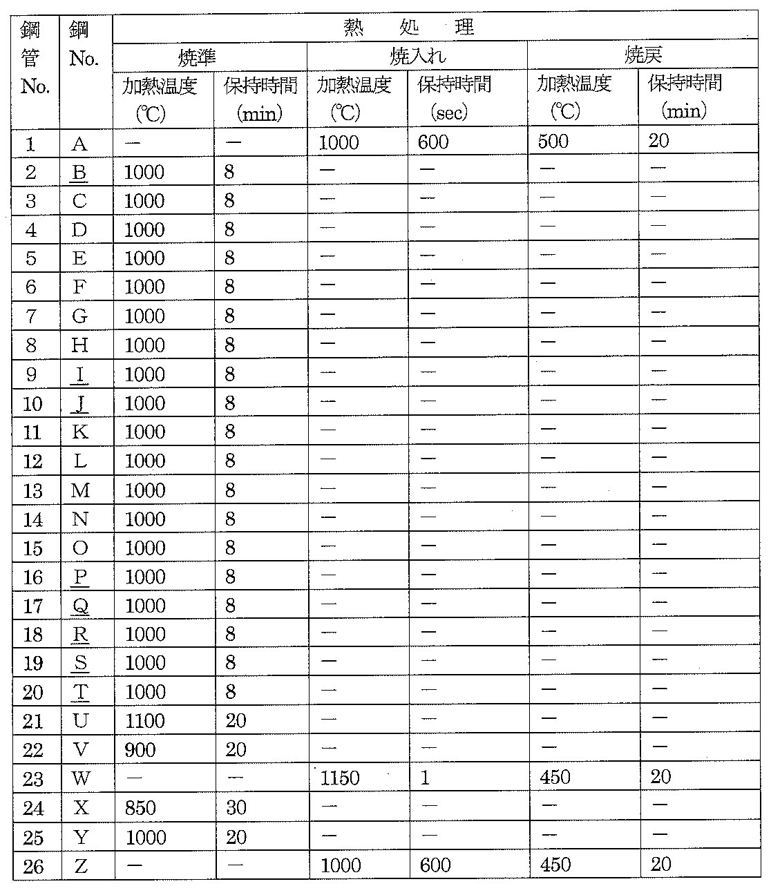
- the steel pipe material having the composition shown in Table 1 is heated to a heating temperature of 1150 to 1250 ° C., pierced and stretched with a Mannesmann-mandrel mill type rolling facility, and further subjected to constant diameter rolling with a stretch reducer. It was a steelless tube (outside diameter 34 mm ⁇ ⁇ inside diameter 25 mm ⁇ ). Using these seamless steel tubes as a raw material, cold drawing was repeated to obtain cold drawn steel tubes (outer diameter 6.4 mm ⁇ ⁇ inner diameter 3.0 mm ⁇ ). Next, the obtained cold-drawn steel pipe was subjected to the heat treatment shown in Table 2.
- Specimens were collected from the obtained seamless steel pipe (cold drawn steel pipe) and subjected to structure observation, tensile test, and internal pressure fatigue test.
- the test method was as follows.
- (1) Microstructure observation A specimen for microstructural observation is collected from the obtained steel pipe, polished so that a cross section perpendicular to the pipe axis direction (cross section in the pipe axis direction) becomes an observation surface, and conforms to the provisions of JIS G 0511. In conformity, the corrosive liquid (saturated aqueous solution of picric acid or nital liquid) corroded, and the revealed structure was observed with an optical microscope (magnification: 200 times), imaged, and the average particle size was analyzed by image analysis.
- an optical microscope magnification: 200 times
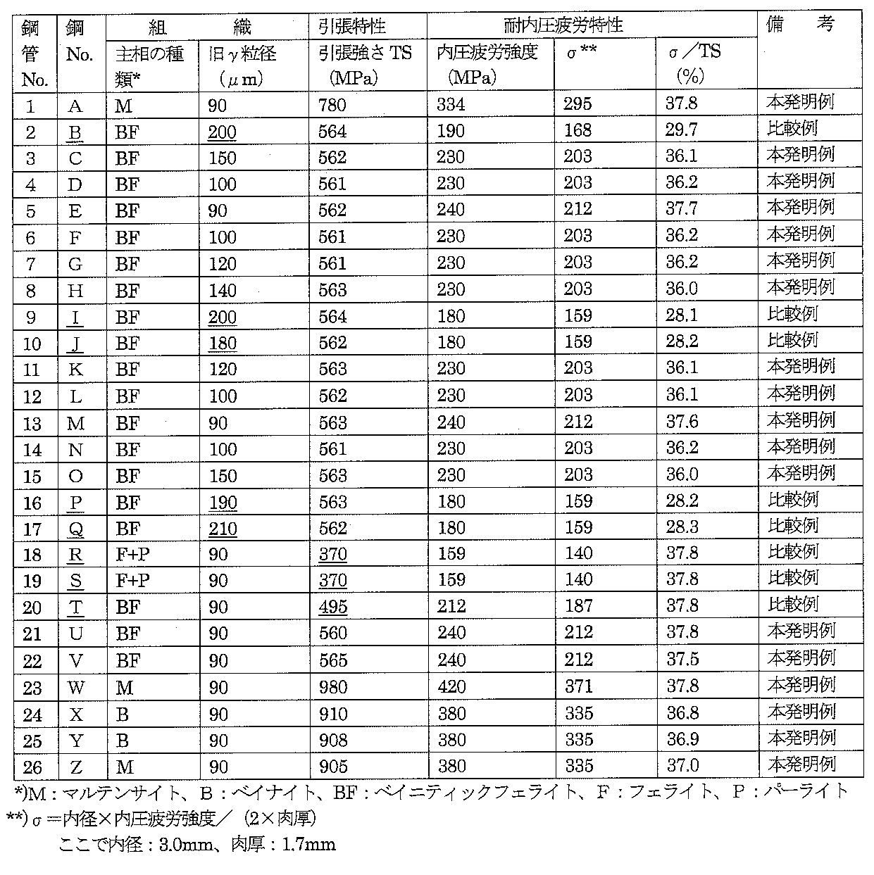
- All of the examples of the present invention have a high strength of tensile strength TS: 500 MPa or more, and the durability ratio ( ⁇ / TS) is 30% or more, and have excellent internal pressure fatigue resistance. It has sufficient characteristics as a steel pipe for fuel injection pipes for diesel engines. On the other hand, in the comparative example which departs from the present invention, the tensile strength is less than 500 MPa, or the internal pressure fatigue resistance ⁇ / TS is lowered to less than 30%.
Abstract
Description
[Al%]×[N%]≦27×10-5 (1)
ここで、Al%、N%:各元素の含有量(質量%)
[2]前記組成に加えてさらに、質量%で、Cu:0.10~0.70%、Ni:0.01~1.0%、Cr:0.1~1.2%、Mo:0.03~0.50%、B:0.0005~0.0060%のうちから選ばれた1種または2種以上を含有することを特徴とする[1]に記載の燃料噴射管用継目無鋼管。 [Al%] × [N%] ≦ 27 × 10 −5 (1)
Here, Al%, N%: content of each element (mass%)
[2] In addition to the above composition, Cu: 0.10 to 0.70%, Ni: 0.01 to 1.0%, Cr: 0.1 to 1.2%, Mo: 0 by mass% A seamless steel pipe for a fuel injection pipe according to [1], comprising one or more selected from 0.03 to 0.50% and B: 0.0005 to 0.0060% .
Cは、固溶して、あるいは析出し、あるいは焼入れ性の向上を介して、鋼管の強度を増加させる作用を有する元素である。このような効果を得て、所望の高強度を確保するためには、Cを0.155%以上含有する必要がある。一方、C含有量が0.38%を超えると、熱間加工性が低下し、所定の寸法形状の鋼管に加工することが困難となる。このため、C含有量は0.155~0.38%の範囲に限定した。なお、好ましくは0.16~0.21%である。 C: 0.155 to 0.38%
C is an element having an action of increasing the strength of the steel pipe through solid solution, precipitation, or improvement of hardenability. In order to acquire such an effect and to secure a desired high strength, it is necessary to contain 0.155% or more of C. On the other hand, when the C content exceeds 0.38%, the hot workability is lowered and it becomes difficult to process into a steel pipe having a predetermined size and shape. Therefore, the C content is limited to the range of 0.155 to 0.38%. Preferably, the content is 0.16 to 0.21%.
Siは、本発明では脱酸剤として作用する元素である。このような効果を得るためには、Siを0.01%以上含有する必要がある。一方、Si含有量が0.49%を超えても、効果が飽和し経済的に不利となる。このため、Si含有量は0.01~0.49%の範囲に限定した。なお、好ましくは、0.15~0.35%である。 Si: 0.01-0.49%
Si is an element that acts as a deoxidizer in the present invention. In order to obtain such an effect, it is necessary to contain 0.01% or more of Si. On the other hand, even if the Si content exceeds 0.49%, the effect is saturated and economically disadvantageous. Therefore, the Si content is limited to the range of 0.01 to 0.49%. Preferably, the content is 0.15 to 0.35%.
Mnは、固溶して、あるいは焼入れ性の向上を介して、鋼管の強度を増加させる作用を有する元素である。このような効果を得て、所望の高強度を確保するためには、Mnを0.6%以上含有する必要がある。一方、Mn含有量が2.1%を超えると、偏析を助長し、鋼管の靭性が低下する。このため、Mn含有量は0.6~2.1%の範囲に限定した。なお、好ましくは1.20~1.40%である。 Mn: 0.6 to 2.1%
Mn is an element having an action of increasing the strength of the steel pipe through solid solution or through improvement of hardenability. In order to obtain such an effect and ensure a desired high strength, it is necessary to contain 0.6% or more of Mn. On the other hand, when the Mn content exceeds 2.1%, segregation is promoted and the toughness of the steel pipe is lowered. Therefore, the Mn content is limited to the range of 0.6 to 2.1%. Preferably, the content is 1.20 to 1.40%.
Alは、脱酸剤として作用するとともに、Nと結合してAlNとして析出し、結晶粒、とくにγ粒の微細化に有効に寄与し、結晶粒微細化を介して耐内圧疲労特性を向上させる元素である。このような効果を得るためには、Alを0.005%以上含有する必要がある。一方、Al含有量が0.25%を超えると、析出するAlNが粗大化し、所望の結晶粒の微細化を達成できず、所望の高靭性および優れた耐内圧疲労特性を確保できなくなる。なお、好ましくは0.015~0.050%である。 Al: 0.005 to 0.25%
Al acts as a deoxidizer and binds to N to precipitate as AlN, effectively contributing to refinement of crystal grains, particularly γ grains, and improving internal pressure fatigue resistance through refinement of crystal grains. It is an element. In order to acquire such an effect, it is necessary to contain Al 0.005% or more. On the other hand, if the Al content exceeds 0.25%, the precipitated AlN becomes coarse, and the desired crystal grain refinement cannot be achieved, and the desired high toughness and excellent internal pressure fatigue resistance characteristics cannot be ensured. Preferably, the content is 0.015 to 0.050%.
Nは、Alと結合してAlNとして析出し、結晶粒、とくにγ粒の微細化に有効に寄与し、結晶粒の微細化を介して耐内圧疲労特性を向上させる元素である。このような効果を得るためには、Nを0.0010%以上含有する必要がある。一方、N含有量が0.010%を超えると、析出するAlNが粗大化し、所望の結晶粒微細化を達成できなくなる。このため、N含有量は0.0010~0.010%の範囲に限定した。なお、冷間引抜き性を低下させる時効硬化の観点から、好ましくは0.0020~0.0050%である。 N: 0.0010 to 0.010%
N is an element that combines with Al and precipitates as AlN, contributes effectively to refinement of crystal grains, particularly γ grains, and improves internal pressure fatigue resistance through refinement of crystal grains. In order to acquire such an effect, it is necessary to contain N 0.0010% or more. On the other hand, if the N content exceeds 0.010%, the precipitated AlN becomes coarse and the desired crystal grain refinement cannot be achieved. Therefore, the N content is limited to the range of 0.0010 to 0.010%. From the viewpoint of age hardening that lowers the cold drawability, the content is preferably 0.0020 to 0.0050%.
Al含有量[Al%]とN含有量[N%]の積([Al%]×[N%])が、(1)式を満足するように調整することにより、旧γ粒径を所定値以下に微細化でき、鋼管靭性および鋼管の耐内圧疲労特性が向上する。一方、[Al%]×[N%]が、(1)式を満足しない、すなわち、[Al%]×[N%]が27×10-5を超えて大きくなると、AlNが粗大化し、結晶粒の微細化作用が低下する。このため、所望の耐内圧疲労特性を確保できなくなる。このようなことから、[Al%]×[N%]が(1)式を満足するように、Al含有量[Al%]とN含有量[N%]を調整することとした。なお、好ましくは[Al%]×[N%]は20×10-5以下である。 [Al%] × [N%] ≦ 27 × 10 −5 (1)
The product of the Al content [Al%] and the N content [N%] ([Al%] × [N%]) is adjusted so as to satisfy the formula (1). The steel pipe toughness and the internal pressure fatigue resistance of the steel pipe are improved. On the other hand, when [Al%] × [N%] does not satisfy the formula (1), that is, when [Al%] × [N%] exceeds 27 × 10 −5 , AlN becomes coarse and crystals The effect of grain refinement is reduced. For this reason, desired internal pressure fatigue resistance cannot be ensured. For this reason, the Al content [Al%] and the N content [N%] are adjusted so that [Al%] × [N%] satisfies the formula (1). [Al%] × [N%] is preferably 20 × 10 −5 or less.
Cu、Ni、Cr、MoおよびBはいずれも、焼入れ性向上を介して強度増加に寄与する元素であり、必要に応じて、1種または2種以上を選択して含有できる。 One or two selected from Cu: 0.70% or less, Ni: 1.00% or less, Cr: 1.20% or less, Mo: 0.50% or less, B: 0.0060% or less As described above, Cu, Ni, Cr, Mo and B are all elements contributing to an increase in strength through the improvement of hardenability, and can be selected from one or two or more as necessary.
Ti、NbおよびVはいずれも、析出強化を介して強度増加に寄与する元素であり、必要に応じて、1種または2種以上を選択して含有できる。 One or two or more selected from Ti: 0.20% or less, Nb: 0.050% or less, V: 0.20% or less Ti, Nb and V are all strengthened through precipitation strengthening. It is an element contributing to the increase, and one or more elements can be selected and contained as necessary.
Caは、介在物の形態制御に寄与する元素であり、必要に応じて含有できる。 Ca: 0.0040% or less Ca is an element contributing to the form control of inclusions, and can be contained as necessary.
(1)組織観察
得られた鋼管から、組織観察用試験片を採取し、管軸方向に直交する断面(管軸方向断面)が観察面となるように、研磨し、JIS G 0511の規定に準拠して、腐食液(ピクリン酸飽和水溶液又はナイタール液)を用いて腐食し、現出した組織について、光学顕微鏡(倍率:200倍)で観察し、撮像して、画像解析により、平均粒径を算出し、当該鋼管の旧γ粒径とした。なお、No.1~17、No.20~26については、ピクリン酸飽和水溶液を用いた。また、No.18、19については、ナイタール液を用い、網目状フェライトの網目の大きさを求めて、旧γ粒径とした。
(2)引張試験
得られた鋼管から、引張方向が管軸方向となるように、JIS 11号試験片を採取し、JIS Z 2241の規定に準拠して、引張試験を実施し、引張特性(引張強さTS)を求めた。
(3)内圧疲労試験
得られた鋼管から、内圧疲労試験片(管状)を採取し、内圧疲労試験を実施した。内圧疲労試験は、管内側に正弦波圧力(内圧)を負荷し、繰返し回数が107回で破壊が起こらない最大内圧を、内圧疲労強度とした。なお、正弦波圧力(内圧)は、最低内圧:18MPa、最高内圧:250~190MPaとした。
得られた結果を表2に示す。 Specimens were collected from the obtained seamless steel pipe (cold drawn steel pipe) and subjected to structure observation, tensile test, and internal pressure fatigue test. The test method was as follows.
(1) Microstructure observation A specimen for microstructural observation is collected from the obtained steel pipe, polished so that a cross section perpendicular to the pipe axis direction (cross section in the pipe axis direction) becomes an observation surface, and conforms to the provisions of JIS G 0511. In conformity, the corrosive liquid (saturated aqueous solution of picric acid or nital liquid) corroded, and the revealed structure was observed with an optical microscope (magnification: 200 times), imaged, and the average particle size was analyzed by image analysis. Was calculated as the old γ grain size of the steel pipe. In addition, No. 1-17, no. For 20 to 26, a saturated aqueous solution of picric acid was used. No. As for Nos. 18 and 19, a nital solution was used, and the mesh size of the mesh ferrite was obtained to obtain the old γ particle size.
(2) Tensile test JIS No. 11 test piece was sampled from the obtained steel pipe so that the tensile direction would be the axial direction of the pipe, and the tensile test was conducted in accordance with the provisions of JIS Z 2241. Tensile strength TS) was determined.
(3) Internal pressure fatigue test From the obtained steel pipe, an internal pressure fatigue test piece (tubular) was sampled and an internal pressure fatigue test was performed. Pressure fatigue test, a sinusoidal pressure (internal pressure) was loaded into the tube side, the maximum internal pressure that the number of repetitions does not occur is broken at 10 7 times, and the internal pressure fatigue strength. The sine wave pressure (internal pressure) was set to a minimum internal pressure of 18 MPa and a maximum internal pressure of 250 to 190 MPa.
The obtained results are shown in Table 2.

Claims (4)
- 質量%で、C:0.155~0.38%、Si:0.01~0.49%、Mn:0.6~2.1%、Al:0.005~0.25%、N:0.0010~0.010%を含み、かつ下記(1)式を満足し、不純物としてのP:0.030%以下、S:0.025%以下、O:0.005%以下を含有し、残部Feおよび不可避的不純物からなる組成を有し、
冷間引抜き、熱処理を施した後の旧γ粒径の平均粒径が、管軸方向断面で、150μm以下である組織を有し、
引張強さTS:500MPa以上であることを特徴とする燃料噴射管用継目無鋼管。
記
[Al%]×[N%]≦27×10-5 (1)
ここで、Al%、N%:各元素の含有量(質量%) In mass%, C: 0.155 to 0.38%, Si: 0.01 to 0.49%, Mn: 0.6 to 2.1%, Al: 0.005 to 0.25%, N: 0.0010 to 0.010% is included, and the following formula (1) is satisfied. P: 0.030% or less, S: 0.025% or less, and O: 0.005% or less as impurities And having a composition consisting of the balance Fe and inevitable impurities,
The average particle size of the old γ particle size after cold drawing and heat treatment has a structure that is 150 μm or less in the cross section in the tube axis direction,
A tensile steel TS: 500 MPa or more, a seamless steel pipe for a fuel injection pipe.
[Al%] × [N%] ≦ 27 × 10 −5 (1)
Here, Al%, N%: content of each element (mass%) - 前記組成に加えてさらに、質量%で、Cu:0.70%以下、Ni:1.00%以下、Cr:1.20%以下、Mo:0.50%以下、B:0.0060%以下のうちから選ばれた1種または2種以上を含有することを特徴とする請求項1に記載の燃料噴射管用継目無鋼管。 In addition to the above composition, Cu: 0.70% or less, Ni: 1.00% or less, Cr: 1.20% or less, Mo: 0.50% or less, B: 0.0060% or less in mass% The seamless steel pipe for a fuel injection pipe according to claim 1, comprising one or more selected from among the above.
- 前記組成に加えてさらに、質量%で、Ti:0.20%以下、Nb:0.050%以下、V:0.20%以下のうちから選ばれた1種または2種以上を含有することを特徴とする請求項1または2に記載の燃料噴射管用継目無鋼管。 In addition to the above composition, the composition further contains one or more selected from Ti: 0.20% or less, Nb: 0.050% or less, and V: 0.20% or less in mass%. The seamless steel pipe for a fuel injection pipe according to claim 1 or 2.
- 前記組成に加えてさらに、質量%で、Ca:0.0040%以下を含有することを特徴とする請求項1ないし3のいずれかに記載の燃料噴射管用継目無鋼管。 The seamless steel pipe for a fuel injection pipe according to any one of claims 1 to 3, further comprising Ca: 0.0040% or less by mass% in addition to the composition.
Priority Applications (5)
| Application Number | Priority Date | Filing Date | Title |
|---|---|---|---|
| EP15773005.2A EP3128025B1 (en) | 2014-04-03 | 2015-03-20 | Seamless steel pipe for fuel injection pipe |
| US15/300,810 US10308994B2 (en) | 2014-04-03 | 2015-03-20 | Seamless steel tube for fuel injection |
| CN201580017608.8A CN106133176B (en) | 2014-04-03 | 2015-03-20 | Pipe as fuel injection seamless steel pipe |
| KR1020167027196A KR101869311B1 (en) | 2014-04-03 | 2015-03-20 | Seamless steel tube for fuel injection |
| MX2016012866A MX2016012866A (en) | 2014-04-03 | 2015-03-20 | Seamless steel pipe for fuel injection pipe. |
Applications Claiming Priority (2)
| Application Number | Priority Date | Filing Date | Title |
|---|---|---|---|
| JP2014-076850 | 2014-04-03 | ||
| JP2014076850A JP6070617B2 (en) | 2014-04-03 | 2014-04-03 | Seamless steel pipe for fuel injection pipes with excellent internal pressure fatigue resistance |
Publications (1)
| Publication Number | Publication Date |
|---|---|
| WO2015151448A1 true WO2015151448A1 (en) | 2015-10-08 |
Family
ID=54239796
Family Applications (1)
| Application Number | Title | Priority Date | Filing Date |
|---|---|---|---|
| PCT/JP2015/001590 WO2015151448A1 (en) | 2014-04-03 | 2015-03-20 | Seamless steel pipe for fuel injection pipe |
Country Status (7)
| Country | Link |
|---|---|
| US (1) | US10308994B2 (en) |
| EP (1) | EP3128025B1 (en) |
| JP (1) | JP6070617B2 (en) |
| KR (1) | KR101869311B1 (en) |
| CN (1) | CN106133176B (en) |
| MX (1) | MX2016012866A (en) |
| WO (1) | WO2015151448A1 (en) |
Cited By (2)
| Publication number | Priority date | Publication date | Assignee | Title |
|---|---|---|---|---|
| GB2550611A (en) * | 2016-05-25 | 2017-11-29 | Delphi Int Operations Luxembourg Sarl | Common rail |
| CN113862556A (en) * | 2021-08-05 | 2021-12-31 | 邯郸新兴特种管材有限公司 | 4140 medium-thick-wall seamless steel pipe and production method thereof |
Families Citing this family (6)
| Publication number | Priority date | Publication date | Assignee | Title |
|---|---|---|---|---|
| CN106555107B (en) * | 2015-09-24 | 2018-11-06 | 宝山钢铁股份有限公司 | A kind of manufacturing method and bainite type high-strength seamless steel pipe of bainite type high-strength seamless steel pipe |
| JP7071222B2 (en) * | 2018-06-07 | 2022-05-18 | 大同特殊鋼株式会社 | Manufacturing method of fuel injection parts |
| CN114836681B (en) * | 2021-02-01 | 2023-09-12 | 宝山钢铁股份有限公司 | High-strength seamless steel pipe with good fatigue resistance and manufacturing method thereof |
| DE102022114337A1 (en) * | 2022-06-08 | 2023-12-14 | Mannesmann Precision Tubes Gmbh | Method for producing a seamless precision steel tube, such precision steel tube and corresponding manufacturing system |
| CN115772634B (en) * | 2022-12-10 | 2024-02-09 | 新余钢铁股份有限公司 | Cr-containing normalized steel plate for nuclear power and manufacturing method thereof |
| CN116377324A (en) * | 2023-03-28 | 2023-07-04 | 鞍钢股份有限公司 | 960 MPa-grade seamless steel tube for ultrahigh-strength high-toughness crane boom and manufacturing method |
Citations (4)
| Publication number | Priority date | Publication date | Assignee | Title |
|---|---|---|---|---|
| JP2004353028A (en) * | 2003-05-28 | 2004-12-16 | Jfe Steel Kk | High carbon steel tube having excellent cold forging workability and rolling workability, and its production method |
| JP2009019503A (en) * | 2007-07-10 | 2009-01-29 | Usui Kokusai Sangyo Kaisha Ltd | Steel pipe for fuel injection pipe and its manufacturing method |
| JP2010106353A (en) * | 2008-10-31 | 2010-05-13 | Usui Kokusai Sangyo Kaisha Ltd | Worked article made of high strength steel having excellent hardenability, method for producing the same, and methods for producing fuel injection pipe and common rail for diesel engine having high strength and excellent impact resistance and inner pressure fatigue resistance |
| JP2012188729A (en) * | 2010-05-27 | 2012-10-04 | Jfe Steel Corp | Electric-resistance-welded steel pipe with excellent torsion fatigue resistance and process for producing the same |
Family Cites Families (12)
| Publication number | Priority date | Publication date | Assignee | Title |
|---|---|---|---|---|
| JPS5033345A (en) | 1973-07-31 | 1975-03-31 | ||
| JPS5065781A (en) | 1973-10-17 | 1975-06-03 | ||
| JP4405102B2 (en) * | 2001-04-11 | 2010-01-27 | 臼井国際産業株式会社 | Common rail for diesel engines |
| US20050076975A1 (en) | 2003-10-10 | 2005-04-14 | Tenaris Connections A.G. | Low carbon alloy steel tube having ultra high strength and excellent toughness at low temperature and method of manufacturing the same |
| KR20070107140A (en) * | 2005-03-25 | 2007-11-06 | 수미도모 메탈 인더스트리즈, 리미티드 | Hollow driving shaft obtained through inducti0n hardening |
| JP4974331B2 (en) * | 2006-02-28 | 2012-07-11 | 株式会社神戸製鋼所 | Steel high-strength processed product excellent in impact resistance and strength-ductility balance and manufacturing method thereof, and fuel injection pipe for diesel engine and common rail manufacturing method excellent in high strength, impact resistance and internal pressure fatigue characteristics |
| JP5033345B2 (en) | 2006-04-13 | 2012-09-26 | 臼井国際産業株式会社 | Steel pipe for fuel injection pipe |
| US8794215B2 (en) * | 2009-03-12 | 2014-08-05 | Nippon Steel & Sumitomo Metal Corporation | Method of producing common rail and common rail |
| JP5728836B2 (en) * | 2009-06-24 | 2015-06-03 | Jfeスチール株式会社 | Manufacturing method of high strength seamless steel pipe for oil wells with excellent resistance to sulfide stress cracking |
| CN102741438B (en) * | 2010-06-03 | 2014-11-05 | 新日铁住金株式会社 | Steel pipe for air bag and process for producing same |
| WO2014119802A1 (en) * | 2013-01-31 | 2014-08-07 | Jfeスチール株式会社 | Electric-resistance-welded steel pipe |
| US9869009B2 (en) * | 2013-11-15 | 2018-01-16 | Gregory Vartanov | High strength low alloy steel and method of manufacturing |
-
2014
- 2014-04-03 JP JP2014076850A patent/JP6070617B2/en active Active
-
2015
- 2015-03-20 CN CN201580017608.8A patent/CN106133176B/en active Active
- 2015-03-20 KR KR1020167027196A patent/KR101869311B1/en active IP Right Grant
- 2015-03-20 EP EP15773005.2A patent/EP3128025B1/en active Active
- 2015-03-20 WO PCT/JP2015/001590 patent/WO2015151448A1/en active Application Filing
- 2015-03-20 US US15/300,810 patent/US10308994B2/en active Active
- 2015-03-20 MX MX2016012866A patent/MX2016012866A/en unknown
Patent Citations (4)
| Publication number | Priority date | Publication date | Assignee | Title |
|---|---|---|---|---|
| JP2004353028A (en) * | 2003-05-28 | 2004-12-16 | Jfe Steel Kk | High carbon steel tube having excellent cold forging workability and rolling workability, and its production method |
| JP2009019503A (en) * | 2007-07-10 | 2009-01-29 | Usui Kokusai Sangyo Kaisha Ltd | Steel pipe for fuel injection pipe and its manufacturing method |
| JP2010106353A (en) * | 2008-10-31 | 2010-05-13 | Usui Kokusai Sangyo Kaisha Ltd | Worked article made of high strength steel having excellent hardenability, method for producing the same, and methods for producing fuel injection pipe and common rail for diesel engine having high strength and excellent impact resistance and inner pressure fatigue resistance |
| JP2012188729A (en) * | 2010-05-27 | 2012-10-04 | Jfe Steel Corp | Electric-resistance-welded steel pipe with excellent torsion fatigue resistance and process for producing the same |
Cited By (2)
| Publication number | Priority date | Publication date | Assignee | Title |
|---|---|---|---|---|
| GB2550611A (en) * | 2016-05-25 | 2017-11-29 | Delphi Int Operations Luxembourg Sarl | Common rail |
| CN113862556A (en) * | 2021-08-05 | 2021-12-31 | 邯郸新兴特种管材有限公司 | 4140 medium-thick-wall seamless steel pipe and production method thereof |
Also Published As
| Publication number | Publication date |
|---|---|
| CN106133176B (en) | 2018-06-05 |
| KR101869311B1 (en) | 2018-06-20 |
| US10308994B2 (en) | 2019-06-04 |
| EP3128025B1 (en) | 2018-07-11 |
| JP2015196895A (en) | 2015-11-09 |
| EP3128025A4 (en) | 2017-02-08 |
| US20170022581A1 (en) | 2017-01-26 |
| JP6070617B2 (en) | 2017-02-01 |
| CN106133176A (en) | 2016-11-16 |
| MX2016012866A (en) | 2016-12-07 |
| EP3128025A1 (en) | 2017-02-08 |
| KR20160130430A (en) | 2016-11-11 |
Similar Documents
| Publication | Publication Date | Title |
|---|---|---|
| WO2015151448A1 (en) | Seamless steel pipe for fuel injection pipe | |
| JP6107437B2 (en) | Manufacturing method of low-alloy high-strength seamless steel pipe for oil wells with excellent resistance to sulfide stress corrosion cracking | |
| US10584396B2 (en) | Heat treatable steel, product formed thereof having ultra high strength and excellent durability, and method for manufacturing same | |
| JP5040197B2 (en) | Hot-rolled thin steel sheet with excellent workability and excellent strength and toughness after heat treatment and method for producing the same | |
| US9708681B2 (en) | High-strength seamless steel pipe for oil well use having excellent resistance to sulfide stress cracking | |
| US9689051B2 (en) | Hollow seamless pipe for high-strength springs | |
| JP5029748B2 (en) | High strength hot rolled steel sheet with excellent toughness and method for producing the same | |
| JP5958450B2 (en) | Low-alloy high-strength seamless steel pipe with excellent resistance to sulfide stress corrosion cracking and its manufacturing method | |
| JP6171851B2 (en) | Apparatus row for seamless steel pipe production and method for producing high-strength stainless steel seamless steel pipe for oil wells using the same | |
| RU2569619C1 (en) | Method of production of low alloyed cold-resistant welded rolled plates with increased corrosion resistant | |
| KR20150002848A (en) | Steel wire for high-strength spring having exceptional coiling performance and hydrogen embrittlement resistance, and method for manufacturing same | |
| JP5845674B2 (en) | High strength steel plate excellent in bending workability and low temperature toughness and method for producing the same | |
| JP6451874B2 (en) | High strength seamless steel pipe for oil well and method for producing the same | |
| JP2009007652A (en) | Thick hot-rolled steel sheet excellent in workability and excellent in strength and toughness after heat-treatment, and method for producing the same | |
| JP2007092131A (en) | High strength thin steel sheet having excellent rigidity, and its production method | |
| JP2007284774A (en) | Wire rod superior in delayed fracture resistance and cold workability, and manufacturing method therefor | |
| JP2015183197A (en) | Low alloy high strength seamless steel pipe for oil well excellent in sulfide stress corrosion cracking resistance and production method thereof, and selection method thereof | |
| JP2011084813A (en) | Workpiece made of high strength steel having excellent notch fatigue strength, and method for producing the same | |
| JP7006154B2 (en) | Manufacturing method of thick steel plate and thick steel plate | |
| JP2019210530A (en) | Manufacturing method of fuel injection component | |
| JP7149352B2 (en) | Steel pipe for fuel injection pipe and fuel injection pipe using the same | |
| JP6747623B1 (en) | ERW steel pipe | |
| JP7163777B2 (en) | Steel plate for line pipe | |
| JP7189238B2 (en) | Steel pipe for fuel injection pipe and fuel injection pipe using the same | |
| JP2013007079A (en) | Thermal refining type low yield ratio thick steel sheet having excellent sour resistance and method for manufacturing the same |
Legal Events
| Date | Code | Title | Description |
|---|---|---|---|
| 121 | Ep: the epo has been informed by wipo that ep was designated in this application |
Ref document number: 15773005 Country of ref document: EP Kind code of ref document: A1 |
|
| REEP | Request for entry into the european phase |
Ref document number: 2015773005 Country of ref document: EP |
|
| WWE | Wipo information: entry into national phase |
Ref document number: 2015773005 Country of ref document: EP |
|
| ENP | Entry into the national phase |
Ref document number: 20167027196 Country of ref document: KR Kind code of ref document: A |
|
| WWE | Wipo information: entry into national phase |
Ref document number: 15300810 Country of ref document: US Ref document number: MX/A/2016/012866 Country of ref document: MX |
|
| NENP | Non-entry into the national phase |
Ref country code: DE |