WO2015151360A1 - Printer - Google Patents
Printer Download PDFInfo
- Publication number
- WO2015151360A1 WO2015151360A1 PCT/JP2014/084191 JP2014084191W WO2015151360A1 WO 2015151360 A1 WO2015151360 A1 WO 2015151360A1 JP 2014084191 W JP2014084191 W JP 2014084191W WO 2015151360 A1 WO2015151360 A1 WO 2015151360A1
- Authority
- WO
- WIPO (PCT)
- Prior art keywords
- paper
- printer
- shaft
- housing
- pair
- Prior art date
Links
Images


Classifications
-
- B—PERFORMING OPERATIONS; TRANSPORTING
- B41—PRINTING; LINING MACHINES; TYPEWRITERS; STAMPS
- B41J—TYPEWRITERS; SELECTIVE PRINTING MECHANISMS, i.e. MECHANISMS PRINTING OTHERWISE THAN FROM A FORME; CORRECTION OF TYPOGRAPHICAL ERRORS
- B41J29/00—Details of, or accessories for, typewriters or selective printing mechanisms not otherwise provided for
- B41J29/02—Framework
-
- B—PERFORMING OPERATIONS; TRANSPORTING
- B41—PRINTING; LINING MACHINES; TYPEWRITERS; STAMPS
- B41J—TYPEWRITERS; SELECTIVE PRINTING MECHANISMS, i.e. MECHANISMS PRINTING OTHERWISE THAN FROM A FORME; CORRECTION OF TYPOGRAPHICAL ERRORS
- B41J15/00—Devices or arrangements of selective printing mechanisms, e.g. ink-jet printers or thermal printers, specially adapted for supporting or handling copy material in continuous form, e.g. webs
- B41J15/04—Supporting, feeding, or guiding devices; Mountings for web rolls or spindles
- B41J15/042—Supporting, feeding, or guiding devices; Mountings for web rolls or spindles for loading rolled-up continuous copy material into printers, e.g. for replacing a used-up paper roll; Point-of-sale printers with openable casings allowing access to the rolled-up continuous copy material
Definitions
- This invention relates to a printer for recording large and heavy roll paper.
- the printer is equipped with electrical system parts for drive control and power supply of each part of the printer, and it is necessary to insulate these electrical system parts. Moreover, when it is set as the structure which hold
- the above-described conventional technique has a problem that the configuration for insulating the electrical system parts provided in a plurality of locations of the printer becomes complicated. Further, since the configuration of the printer is complicated, there are problems that the number of manufacturing steps is increased, the burden on the worker for manufacturing is large, and the manufacturing cost is increased. Specifically, for example, each electrical system component is installed in an insulated state, and a metal frame that has been painted with a paint with high electrical insulation is provided separately. There is a problem that the burden on the user is large and the manufacturing cost is increased.
- An object of the present invention is to reduce the manufacturing cost of a printer that secures the strength to hold a large-diameter roll paper in order to eliminate the above-described problems caused by the prior art.
- a printer includes a housing having a substantially box shape and a pair of housings provided in the housing and arranged to face each other with a conveyance path for the recording medium therebetween.
- a shaft for holding the paper so that it can be pulled out from the housing, an opening provided in the housing using an insulating material, and opening the notch to the outside is provided.
- an exterior cover that covers the pair of frames in a state in which the notch is opened to the outside.
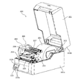
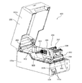
- FIG. 1 is an explanatory view showing the appearance of a printer according to an embodiment of the present invention.
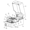
- FIG. 2 is an explanatory diagram (part 1) illustrating the printer with the housing open.
- FIG. 3 is an explanatory diagram (part 2) illustrating the printer with the housing opened.
- FIG. 4 is a side view (part 1) illustrating the head unit and the printer main body.
- FIG. 5 is a side view (part 2) illustrating the head unit and the printer main body.
- FIG. 6 is an explanatory diagram (part 1) illustrating the printer with the housing opened.
- FIG. 7 is an explanatory diagram (part 2) illustrating the printer with the housing opened.
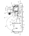
- FIG. 8 is an explanatory diagram (No. 1) showing a top surface and a cross section of the printer according to the embodiment of the invention.
- FIG. 1 is an explanatory diagram showing a top surface and a cross section of the printer according to the embodiment of the invention.
- FIG. 1 is an explanatory diagram showing a top surface and a cross section
- FIG. 1 is an explanatory view showing the appearance of a printer according to an embodiment of the present invention.
- FIG. 1 shows a state in which the printer according to the embodiment of the present invention is viewed obliquely from above in the installed state.
- a printer 100 includes a housing 101 having a hollow rectangular shape.
- the housing 101 includes a lower housing 101a having a substantially box shape with an opening on the upper surface, and an upper housing 101b that closes the opening of the lower housing 101a so as to be openable.
- the upper housing 101b has an opening on the lower surface, and closes the opening of the lower housing 101a with the opening facing the opening of the lower housing 101a.
- the upper housing 101b is rotatably connected to the lower housing 101a by being pivotally supported by the lower housing 101a on the back side of the printer 100 (the right side in FIG. 1).
- an operation panel 103 is provided in front of the housing 101 (lower housing 101a).
- the operation panel 103 includes a plurality of buttons 103a that accept various input operations, and a display panel 103b that displays the status of the printer 100 and the like.
- the display panel 103b is, for example, when the printer 100 is turned on and enters a print standby state, when an error occurs in the printer 100, or when the remaining amount of paper held by the printer 100 falls below a predetermined level. A predetermined message is displayed to notify the status of the printer 100.
- the display panel 103b can be realized by a liquid crystal display, for example.
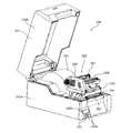
- FIG. 2 and 3 are explanatory views showing the printer 100 with the housing 101 opened.
- FIG. 2 shows a state in which the printer 100 with the inside of the housing 101 opened to the outside is viewed from the upper position on the right side when facing the front surface of the printer 100.
- FIG. 3 shows a state viewed from a position on the upper left side in a state of facing the front surface of the printer 100.
- the printer 100 includes a paper holding unit 202 that holds a recording medium (paper) 201 to be recorded in a rolled state on the back side in the housing 101.
- the recording medium (paper) 201 to be recorded may be continuous paper wound in a roll shape, or may be label paper in which a plurality of labels are arranged along the longitudinal direction of the mount.
- the printer 100 includes a head unit 203 provided on the front side of the sheet holding unit 202 in the housing 101. Inside the housing 101, a conveyance path from the sheet holding unit 202 to the discharge port 102 via the head unit 203 is formed. The paper 201 wound in a roll shape held by the paper holding unit 202 is pulled out from the end on the outer peripheral side in the length direction during the recording operation in the printer 100, and is discharged through the head unit 203. Is conveyed to 102.
- the head unit 203 includes a print head 204.
- the print head 204 performs, for example, a thermal recording operation.
- the print head 204 that performs the thermal recording operation includes, for example, a plurality of heating elements arranged in a line along the width direction of the printer 100 (a direction orthogonal to the conveyance direction of the paper 201).
- the printer 100 performs a recording operation by selectively energizing each heating element in the thermal head and selectively heating each heating element.
- the head unit 203 may include a print head 204 that performs recording by another recording method instead of the thermal recording.
- a platen 205 disposed to face the print head 204 with a conveyance path (paper 201 conveyed in the conveyance path) therebetween.
- the platen 205 has a substantially cylindrical shape with the width direction of the printer 100 as the axial direction.
- the platen 205 supports, from the back surface side, the paper 201 to which a pressing force is applied from the front surface (recording surface) side by the print head 204 during the recording operation.
- the print head 204 is biased in a direction in which the print head 204 comes into contact with the platen 205.
- a motor (see reference numeral 507 in FIG. 5) is attached to one end of the shaft of the platen 205 via a gear train (not shown).
- the gear train rotates when the driving force of the motor is transmitted.
- the platen 205 rotates as the gears constituting the gear train rotate.
- the platen 205 rotates to convey the sheet 201 in the conveyance path from the sheet holding unit 202 side to the discharge port 102 side.
- the head unit 203 includes a ribbon unit 206 that supports an ink ribbon (not shown).
- the ribbon unit 206 includes a ribbon support shaft 207 that supports the ink ribbon before being subjected to the recording operation, and a ribbon take-up shaft 208 that winds up the ink ribbon after the recording operation.
- the ribbon unit 206 also includes a ribbon shaft drive mechanism that rotates the ribbon take-up shaft 208 so that the ink ribbon supported by the ribbon support shaft 207 is taken out and the taken-out ink ribbon is taken up by the ribbon take-up shaft 208.
- the ribbon shaft driving mechanism is housed in the case 209, and includes a motor (see reference numeral 405 in FIG. 5), a train wheel that transmits the driving force of the motor to the ribbon take-up shaft 208, and a ribbon substrate that drives the motor. Consists of.
- FIG. 4 and 5 are side views showing the head unit 203 and the printer main body.
- 4 shows a state where the printer main body with the housing 101 removed is viewed along the direction of arrow A in FIG.
- FIG. 5 shows a state in which the printer main body with the housing 101 removed is viewed along the direction of arrow B in FIG. 4 and 5 show a state where the case 209 in the ribbon unit 206 is removed.
- the printer main body 400 includes a bottom frame 401 provided in the housing 101.
- the bottom frame 401 is formed by sheet metal processing a metal plate member having a predetermined thickness.
- the bottom frame 401 is provided with a pair of shaft paper guides 402 and 501 that realize a pair of frames.
- the pair of shaft paper guides 402 and 501 are provided in the housing 101 at the position of the paper holding unit 202.
- the pair of shaft paper guides 402 and 501 are disposed to face each other along the width direction of the printer 100.
- the pair of shaft paper guides 402 and 501 when the paper holding unit 202 holds the paper 201 wound in a roll shape, sandwiches the paper 201 wound in the roll shape. It arrange
- Notches 402a and 501a are provided at the upper ends of the pair of shaft paper guides 402 and 501, respectively.
- the cutout portions 402a and 501a have a rectangular shape with the upper side (the upper portion in FIG. 4 and FIG. 5) open.
- the notches 402 a and 501 a support a shaft 403 that holds the paper 201 wound in a roll shape accommodated in the paper holding unit 202 so that the paper 201 can be pulled out from the paper holding unit 202.
- the shaft 403 can be realized by a rod-shaped member having a polygonal cross section (for example, a square shape).
- the shaft 403 is formed using an insulating material such as a plastic material.
- the notches 402a and 501a are formed by notching a part of the upper end portion of the pair of shaft paper guides 402 and 501 with a size and shape substantially matching the outer shape of the cross section of the shaft 403.
- the shaft 403 is supported by the pair of shaft paper guides 402 and 501 by fitting both ends into notches 402a and 501a provided in the pair of shaft paper guides 402 and 501, respectively.
- the shaft 403 is detachably attached to the paper holding unit 202.
- the shaft 403 is removed from the paper holding unit 202 when the paper 201 is replaced.
- the paper holding unit 202 supports the shaft 403 inserted inside the winding core of the paper 201 in a roll shape by supporting the shaft 403 with a pair of shaft paper guides 402 and 501, thereby forming the roll.
- the wound long sheet 201 is held in a state where it can be pulled out from the end on the outer peripheral side in the length direction. Since the shaft 403 is inserted inside the winding core and is not fixed to the winding core, the shaft 403 supports the winding core of the paper 201 in a rotatable state around the shaft 403. Thus, by rotating the winding core of the sheet 201 around the shaft 403, the sheet 201 accommodated in the sheet holding unit 202 can be pulled out from the end on the outer peripheral side in the length direction.
- the pair of shaft paper guides 402 and 501 are each formed by subjecting a metal plate member having a predetermined thickness to sheet metal processing.
- the pair of shaft paper guides 402 and 501 is a large-diameter roll paper in which the weight of the paper 201 wound in a roll shape is large by forming each of the pair of shaft paper guides 402 and 501 with a metal plate-like member having a predetermined thickness.
- both ends of the shaft 403 inserted inside the winding core of the paper 201 can be stably and reliably supported.
- the first spring can be realized by a compression coil spring that compresses the damper shaft 504 from the upper side to the lower side in FIG. Further, the first spring biases the damper arm 505 from the upper side to the lower side when the damper arm 505 rotates from the lower side to the upper side.
- the second spring can be realized by a compression coil spring that compresses the damper shaft 504 from the lower side to the upper side in FIG. Further, the second spring biases the damper arm 505 from the lower side to the upper side when the damper arm 505 rotates from the upper side to the lower side.
- the sheet 201 held by the sheet holding unit 202 is a so-called externally wound sheet in which a surface on the outer peripheral side is a recording surface in a state of being wound in a roll shape
- the sheet 201 is a damper in the conveyance path.
- the shaft 504 is guided so as to come into contact with the paper 201 from the lower side in FIG. 4 and FIG.
- the paper 201 held by the paper holding unit 202 is a so-called inner-wound paper in which the surface on the inner peripheral side becomes a recording surface in a state wound in a roll shape
- the paper 201 is The damper shaft 504 is guided so as to come into contact with the sheet 201 from the upper side in FIG. 4 and FIG. In the transport path, the sheet 201 is guided so as to be in contact with the damper shaft 504 between the sheet holding unit 202 and the head unit 203 and bend at the contact position.
- the conveyance force of the platen 205 is applied to the sheet 201 in a state where the recording operation is not performed, the inertia force due to the weight of the sheet 201 wound in a roll shape in the sheet holding unit 202
- the paper 201 is pulled so as to stretch linearly between the platen 205 and the paper holding unit 202. That is, the conveyance force of the platen 205 is applied to the paper 201 in a state in which an inertial force is applied to maintain the stopped state due to the weight of the paper 201 wound in a roll shape in the paper holding unit 202.
- the damper mechanism 503 includes a biasing member that biases the damper arm 505 in a direction in which the damper shaft 504 abuts the paper 201. Therefore, when the paper 201 is pulled linearly, Then, the damper shaft 504 is elastically brought into contact with the sheet, and is urged in a direction in which the sheet 201 is bent. Thus, regardless of whether the sheet is an outer winding sheet or an inner winding sheet, the tension of the sheet 201 can be buffered and the impact (inertial force) applied to the sheet 201 can be reduced, and the sheet 201 can be conveyed accurately.
- the feeding speed of the paper 201 can be made constant.
- the ribbon unit 206 includes a pair of ribbon frames 406 (406a and 406b) that support the ribbon support shaft 207 and the ribbon take-up shaft 208.
- the ribbon frame 406 (406a, 406b) includes a ribbon support shaft 207 and a ribbon take-up shaft 208 at both end positions in the axial center direction of the ribbon support shaft 207 and the ribbon take-up shaft 208. 208 is supported so as to be rotatable around the axis.
- the printer main body 400 includes electrical system components that drive and control each unit included in the printer 100.
- the electrical system components include a control board (not shown), a power supply board (not shown), an interface board 520, a relay board 530, a ribbon board 540, various cables, and the like.
- the control board is fixedly erected on a bracket (not shown) fixed to the bottom frame 401 outside the shaft paper guide 501.
- the control board includes a CPU, a memory, and the like that perform energization control of the print head 204, drive control of the motor 507 that drives the platen 205, drive control of the motor that drives the ribbon support shaft 207 and the ribbon take-up shaft 208, and the like. .
- the relay substrate 530 is provided on the left side between the head unit 203 and the paper holding unit 202.
- the relay substrate 530 is fixed on the bracket 407 fixed to the bottom frame 401.
- the relay board 530 is connected to the control board via a cable (not shown).
- the ribbon substrate 540 is attached to one ribbon frame 406a. Connected to the ribbon substrate 540 are a motor 405 for driving the ribbon support shaft 207 and the ribbon take-up shaft 208, a ribbon rotation detection sensor, a ribbon tension sensor (both not shown), and the like.
- the ribbon substrate 540 is connected to the connector 531 of the relay substrate 530 via the cable 506.
- the cable 506 By fixing the cable 506 at a position on or near the rotation center axis of the head unit 203 with respect to the printer main body 400, the cable 506 is pulled due to the rotation of the head unit 203. It can suppress damaging by rubbing.
- a power supply is supplied to various sensors such as a print head 204 provided in the head unit 203 and a sensor for detecting the position of the paper 201, and a control signal is output.
- the cable may be fixed.
- the head unit 203 is attached to the printer main body 400 via an axis (not shown) whose axial direction is a direction parallel to the conveyance direction of the sheet 201 conveyed in the conveyance path (the length direction of the sheet 201). It is connected so that it can rotate.
- the printer main body 400 is provided with a lock mechanism (not shown) that locks the head unit 203 while the head unit 203 is fixed to the printer main body 400.
- the printer main body 400 is provided with a lock release lever 404 for releasing the lock of the lock mechanism.
- the lock release lever 404 is rotatably connected to the printer main body 400.
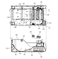
- FIG. 10 shows a state where the printer 100 is viewed from above with the upper housing 101b removed from the lower housing 101a and a part of the printer main body 400 exposed.
- the EE cross section of the top view in the upper part of FIG. 10 is shown.
- the exterior cover 600 includes an opening 601 that exposes a surface facing the paper 201 held by the paper holding unit 202 in one shaft paper guide 501 on the side where a part of the electrical system parts is provided.
- the opening 601 opens a notch 501a provided in one shaft paper guide 501 to the outside.
- the paper 201 held by the paper holding unit 202 is positioned in the printer 100 by bringing the side surface in the wound state into contact with the surface exposed from the exterior cover 600 of the shaft paper guide.
- the shaft paper guides 402 and 501 are formed by sheet metal processing of a metal plate member having a predetermined thickness, the processing accuracy is high.
- the bottom frame 401 is formed by sheet metal processing of a metal plate member having a predetermined thickness, so that the processing accuracy is high.
- the exterior cover 600 includes an opening 602 that opens a notch 402a provided in the shaft paper guide 402 on the side where no electrical system component is provided.
- the exterior cover 600 covers the pair of shaft paper guides 402 and 501 with the notches 402a and 501a open to the outside by the opening 601 and the opening 602 when attached to the housing 101 (lower housing 101a).
- the exterior cover 600 includes a bottom part 801 and a guide part 802.
- the bottom part 801 has an arc shape along the outer diameter of the paper 201 held by the paper holding unit 202.
- the exterior cover 600 includes a side wall portion 603 that covers the shaft paper guide 402 on the side of the pair of shaft paper guides 402 and 501, on which the electrical system component is not provided.
- the opening 602 is formed by cutting out a part of the side wall portion 603.
- the exterior cover 600 is realized by a single member formed by a method such as injection molding using a plastic material.
- the shaft paper guides 402 and 501 as a pair of frames are formed using a metal material such as a sheet metal member, whereby the strength of the pair of shaft paper guides 402 and 501 is increased. Even when the pair of shaft paper guides 402 and 501 is formed using a metal material, the exterior cover 600 does not perform the coating process on the pair of shaft paper guides 402 and 501. By simply covering the pair of shaft paper guides 402 and 501, the pair of shaft paper guides 402 and 501 can be insulated from the outside easily and reliably. Thereby, it is possible to reduce the manufacturing cost of the printer 100 that secures the strength to hold the large-diameter roll paper.
- the cutout portions 402a and 501a are provided in the exterior cover 600, only by covering the pair of shaft paper guides 402 and 501 with the exterior cover 600, A state in which both ends of the shaft 403 are reliably supported by the pair of shaft paper guides 402 and 501 with the pair of shaft paper guides 402 and 501 insulated from the outside can be easily and reliably configured. As a result, the man-hours for manufacturing the printer 100 can be reduced, the burden on the operator for manufacturing the printer 100 can be reduced, and the cost for manufacturing the printer 100 can be reduced.
- the printer 100 is provided in the housing 101, and electrical system components (a control board and a power supply board, an interface board 520, a relay board, not shown) that are used for driving each part of the printer 100 are provided. 530, ribbon substrate 540, various cables, etc.), and the exterior cover 600 further covers electrical system components.
- the printer according to the present invention is useful for a printer whose recording target is a sheet obtained by winding a long sheet in a roll shape, and particularly, a large and heavy roll paper is a recording target. Suitable for printers.
Abstract
A printer (100) equipped with: a roughly box-shaped housing (101); a pair of paper shaft guides that are provided inside the housing (101) and are disposed opposite each other with the print medium conveyance path therebetween; respective notches provided at the upper ends of the paired paper shaft guides; and a shaft (403), which, as a result of the two ends of the shaft being supported by the notches when the shaft is inserted inside a winding core on which long paper is wound in a rolled form, holds the paper so that the paper can be drawn out from the housing (101). The printer is provided with masking cover (600), which: is provided inside the housing (101) and is formed using an insulating material; is provided with openings (602) that leave the notches open to the outside; and covers the pair of frames with the notches open to the outside via said openings (602).
Description
この発明は、大型で重量のあるロール紙を記録対象とするプリンタに関する。
This invention relates to a printer for recording large and heavy roll paper.
従来、ロール状に巻回された状態の長尺状の用紙(ロール紙)に対して記録動作をおこなうプリンタがあった。このようなプリンタにおいては、ロール状にした状態における直径が大きかったり幅が広かったりするために大型で重量のあるロール紙を記録対象として用いる場合、ロール紙を保持するフレームを、或る程度の厚みのある金属製の板状部材によって形成することによって、ロール紙を保持する機構の強度を確保するようにしていた。
Conventionally, there has been a printer that performs a recording operation on a long sheet (roll paper) wound in a roll shape. In such a printer, when a large and heavy roll paper is used as a recording target because the diameter in a roll state is large or the width is wide, a frame for holding the roll paper is used to some extent. The strength of the mechanism that holds the roll paper is ensured by forming it with a thick metal plate-like member.
プリンタは、プリンタが備える各部の駆動制御や給電のための電気系統部品を備えており、これらの電気系統部品を絶縁する必要がある。また、金属製のフレームを用いてロール紙を保持する構成とする場合、当該フレームを絶縁する必要がある。従来、たとえば、金属製のフレームに、電気絶縁性の高い塗料を用いた塗装を施すことにより、フレームの絶縁性を確保するようにしていた。
The printer is equipped with electrical system parts for drive control and power supply of each part of the printer, and it is necessary to insulate these electrical system parts. Moreover, when it is set as the structure which hold | maintains roll paper using a metal frame, it is necessary to insulate the said frame. Conventionally, for example, a metal frame is coated with a paint having a high electrical insulation property to ensure the insulation of the frame.
ロール紙を記録対象とするプリンタに関連する技術として、たとえば、ラベルプリンタにおいて、円筒状を有してラベルシートの巻芯部に挿入可能な第1の径の本体芯部と、本体芯部の長手方向中腹部の所定部位に設けられる第1の径よりも小さい第2の径のラベルシート装着部とを有するラベルシート装着用のコアシャフトを回転可能に支持するように構成した技術があった(たとえば、下記特許文献1、特許文献2を参照。)。
As a technique related to a printer for recording roll paper, for example, in a label printer, a main body core portion of a first diameter that has a cylindrical shape and can be inserted into a core portion of a label sheet; There has been a technology configured to rotatably support a core shaft for attaching a label sheet having a label sheet attaching portion having a second diameter smaller than the first diameter provided at a predetermined portion of the middle part in the longitudinal direction. (For example, refer to Patent Document 1 and Patent Document 2 below.)
しかしながら、上述した従来の技術は、プリンタの複数箇所にわたって設けられている電気系統部品を絶縁するための構成が複雑になってしまうという問題があった。また、プリンタの構成が複雑になることにより、製造工数が増え、製造にかかる作業者の負担が大きく、製造コストがかかってしまうという問題があった。具体的には、たとえば、各電気系統部品を絶縁した状態で取り付け、電気絶縁性の高い塗料を用いた塗装を施した金属製のフレームを別途設けていたため、製造工数が増え、製造にかかる作業者の負担が大きく、製造コストがかかってしまうという問題があった。
However, the above-described conventional technique has a problem that the configuration for insulating the electrical system parts provided in a plurality of locations of the printer becomes complicated. Further, since the configuration of the printer is complicated, there are problems that the number of manufacturing steps is increased, the burden on the worker for manufacturing is large, and the manufacturing cost is increased. Specifically, for example, each electrical system component is installed in an insulated state, and a metal frame that has been painted with a paint with high electrical insulation is provided separately. There is a problem that the burden on the user is large and the manufacturing cost is increased.
また、上述した従来の技術は、フレームの絶縁性を確保するため、当該フレームに電気絶縁性の高い塗料を用いた塗装を施すことにより製造工数が増え、製造にかかる作業者の負担が大きく、製造コストがかかってしまうという問題があった。
Moreover, in order to ensure the insulation of the frame, the conventional technology described above increases the number of manufacturing steps by applying the paint using a paint having a high electrical insulation to the frame, and the burden on the worker for the production is large. There was a problem that the manufacturing cost was increased.
この発明は、上述した従来技術による問題点を解消するため、大径のロール紙を保持する強度を確保したプリンタにかかる製造コストの低減を図ることを目的とする。
SUMMARY OF THE INVENTION An object of the present invention is to reduce the manufacturing cost of a printer that secures the strength to hold a large-diameter roll paper in order to eliminate the above-described problems caused by the prior art.
上述した課題を解決し、目的を達成するため、この発明にかかるプリンタは、略箱形状をなすハウジングと、前記ハウジング内に設けられ、記録媒体の搬送経路を間にして対向配置された一対のフレームと、前記一対のフレームの上端にそれぞれ設けられた切り欠き部と、長尺状の用紙がロール状に巻回される巻き芯の内側に挿入された状態で前記切り欠き部に両端を支持されることにより、前記用紙を前記ハウジングから引き出し可能に保持するシャフトと、前記ハウジング内に設けられて絶縁材料を用いて形成され、前記切り欠き部を外部に開放する開口が設けられ、当該開口を介して前記切り欠き部を外部に開放した状態で前記一対のフレームを覆う外装カバーと、を備えたことを特徴とする。
In order to solve the above-described problems and achieve the object, a printer according to the present invention includes a housing having a substantially box shape and a pair of housings provided in the housing and arranged to face each other with a conveyance path for the recording medium therebetween. A frame, a notch provided at each of the upper ends of the pair of frames, and both ends supported by the notch in a state where a long sheet of paper is inserted inside a roll core wound in a roll shape Thus, a shaft for holding the paper so that it can be pulled out from the housing, an opening provided in the housing using an insulating material, and opening the notch to the outside is provided. And an exterior cover that covers the pair of frames in a state in which the notch is opened to the outside.
また、この発明にかかるプリンタは、上記の発明において、前記ハウジング内に設けられ、前記プリンタが備える各部の駆動にかかる電気系統部品を備え、前記外装カバーが、さらに、前記電気系統部品を覆うことを特徴とする。
Further, the printer according to the present invention includes an electrical system component provided in the housing for driving each part of the printer, and the exterior cover further covers the electrical system component. It is characterized by.
この発明にかかるプリンタによれば、大径のロール紙を保持する強度を確保したプリンタにかかる製造コストの低減を図ることができるという効果を奏する。
According to the printer of the present invention, it is possible to reduce the manufacturing cost of the printer that secures the strength for holding the large-diameter roll paper.
以下に添付図面を参照して、この発明にかかるプリンタの好適な実施の形態を詳細に説明する。
Hereinafter, preferred embodiments of a printer according to the present invention will be described in detail with reference to the accompanying drawings.
まず、この発明にかかる実施の形態のプリンタの構成について説明する。図1は、この発明にかかる実施の形態のプリンタの外観を示す説明図である。図1においては、この発明にかかる実施の形態のプリンタを、設置状態における斜め上方から見た状態を示している。
First, the configuration of the printer according to the embodiment of the present invention will be described. FIG. 1 is an explanatory view showing the appearance of a printer according to an embodiment of the present invention. FIG. 1 shows a state in which the printer according to the embodiment of the present invention is viewed obliquely from above in the installed state.
図1において、この発明にかかる実施の形態のプリンタ100は、中空の長方体形状をなすハウジング101を備えている。ハウジング101は、上面に開口を備えて略箱形形状をなす下側ハウジング101aと、下側ハウジング101aの開口を開放可能に閉塞する上側ハウジング101bと、を備えている。
1, a printer 100 according to an embodiment of the present invention includes a housing 101 having a hollow rectangular shape. The housing 101 includes a lower housing 101a having a substantially box shape with an opening on the upper surface, and an upper housing 101b that closes the opening of the lower housing 101a so as to be openable.
上側ハウジング101bは、下面に開口を備え、当該開口を下側ハウジング101aの開口に対向させた状態で下側ハウジング101aの開口を閉塞する。上側ハウジング101bは、プリンタ100の背面側(図1における紙面右側)において、下側ハウジング101aに軸支されることにより、下側ハウジング101aに対して回動可能に連結されている。
The upper housing 101b has an opening on the lower surface, and closes the opening of the lower housing 101a with the opening facing the opening of the lower housing 101a. The upper housing 101b is rotatably connected to the lower housing 101a by being pivotally supported by the lower housing 101a on the back side of the printer 100 (the right side in FIG. 1).
ハウジング101は、上側ハウジング101bにより下側ハウジング101aの開口を閉塞した状態において、上側ハウジング101bと下側ハウジング101aとの内側にプリンタ本体(図4および図5を参照)を収容する収容空間を形成する。また、ハウジング101は、上側ハウジング101bにより下側ハウジング101aの開口を閉塞した状態において、ハウジング101の前面(図1における紙面左側)に、記録済みの記録媒体を排出する排出口102を形成する。排出口102は、上側ハウジング101bと下側ハウジング101aとの境界部分に形成される。
The housing 101 forms an accommodation space for accommodating the printer main body (see FIGS. 4 and 5) inside the upper housing 101b and the lower housing 101a in a state where the opening of the lower housing 101a is closed by the upper housing 101b. To do. In addition, the housing 101 forms a discharge port 102 for discharging a recorded recording medium on the front surface of the housing 101 (left side in FIG. 1) in a state where the opening of the lower housing 101a is closed by the upper housing 101b. The discharge port 102 is formed at a boundary portion between the upper housing 101b and the lower housing 101a.
ハウジング101の外表面において、当該ハウジング101(下側ハウジング101a)の前面には、操作パネル103が設けられている。操作パネル103は、各種の入力操作を受け付ける複数のボタン103aと、プリンタ100の状態などを表示する表示パネル103bと、を備えている。
On the outer surface of the housing 101, an operation panel 103 is provided in front of the housing 101 (lower housing 101a). The operation panel 103 includes a plurality of buttons 103a that accept various input operations, and a display panel 103b that displays the status of the printer 100 and the like.
表示パネル103bは、たとえば、プリンタ100の電源が投入されて印刷待機状態になった場合や、プリンタ100においてエラーが発生した場合、またはプリンタ100が保持する用紙の残量が所定以下になった場合などに所定のメッセージを表示して、プリンタ100の状態を報知する。表示パネル103bは、たとえば、液晶ディスプレイによって実現することができる。
The display panel 103b is, for example, when the printer 100 is turned on and enters a print standby state, when an error occurs in the printer 100, or when the remaining amount of paper held by the printer 100 falls below a predetermined level. A predetermined message is displayed to notify the status of the printer 100. The display panel 103b can be realized by a liquid crystal display, for example.
図2および図3は、ハウジング101を開放した状態のプリンタ100を示す説明図である。図2においては、ハウジング101の内側を外部に開放した状態のプリンタ100を、当該プリンタ100の前面に正対した状態で右側の上方となる位置から見た状態を示している。図3においては、当該プリンタ100の前面に正対した状態で左側の上方となる位置から見た状態を示している。
2 and 3 are explanatory views showing the printer 100 with the housing 101 opened. FIG. 2 shows a state in which the printer 100 with the inside of the housing 101 opened to the outside is viewed from the upper position on the right side when facing the front surface of the printer 100. FIG. 3 shows a state viewed from a position on the upper left side in a state of facing the front surface of the printer 100.
図2および図3において、プリンタ100は、ハウジング101内における背面側において、記録対象とする記録媒体(用紙)201を、ロール状に巻回された状態で保持する用紙保持部202を備えている。記録対象とする記録媒体(用紙)201は、ロール状に巻回された状態の連続紙であってもよく、台紙の長手方向に沿ってラベルが複数配列されたラベル用紙であってもよい。
2 and 3, the printer 100 includes a paper holding unit 202 that holds a recording medium (paper) 201 to be recorded in a rolled state on the back side in the housing 101. . The recording medium (paper) 201 to be recorded may be continuous paper wound in a roll shape, or may be label paper in which a plurality of labels are arranged along the longitudinal direction of the mount.
プリンタ100は、ハウジング101内において用紙保持部202より前面側に設けられたヘッドユニット203を備えている。ハウジング101の内側には、用紙保持部202からヘッドユニット203を経由して排出口102へ至る搬送経路が形成される。用紙保持部202が保持するロール状に巻回された状態の用紙201は、プリンタ100における記録動作に際して、長さ方向における外周側の端部から引き出されて、ヘッドユニット203を経由して排出口102へ搬送される。
The printer 100 includes a head unit 203 provided on the front side of the sheet holding unit 202 in the housing 101. Inside the housing 101, a conveyance path from the sheet holding unit 202 to the discharge port 102 via the head unit 203 is formed. The paper 201 wound in a roll shape held by the paper holding unit 202 is pulled out from the end on the outer peripheral side in the length direction during the recording operation in the printer 100, and is discharged through the head unit 203. Is conveyed to 102.
ヘッドユニット203は、プリントヘッド204を備えている。プリントヘッド204は、たとえば、サーマル方式の記録動作をおこなう。サーマル方式の記録動作をおこなうプリントヘッド204は、たとえばプリンタ100の幅方向(用紙201の搬送方向に直交する方向)に沿ってライン状に配列された複数の発熱素子を備えている。
The head unit 203 includes a print head 204. The print head 204 performs, for example, a thermal recording operation. The print head 204 that performs the thermal recording operation includes, for example, a plurality of heating elements arranged in a line along the width direction of the printer 100 (a direction orthogonal to the conveyance direction of the paper 201).
プリンタ100は、サーマルヘッドにおける各発熱素子に対して選択的に通電し、各発熱素子を選択的に発熱させることによって記録動作をおこなう。ヘッドユニット203は、サーマル方式の記録に代えて、他の記録方式によって記録をおこなうプリントヘッド204を備えていてもよい。
The printer 100 performs a recording operation by selectively energizing each heating element in the thermal head and selectively heating each heating element. The head unit 203 may include a print head 204 that performs recording by another recording method instead of the thermal recording.
ハウジング101内には、搬送経路(搬送経路中を搬送される用紙201)を間にしてプリントヘッド204に対向配置されたプラテン205が設けられている。プラテン205は、プリンタ100の幅方向を軸心方向とする略円柱形状をなす。プラテン205は、記録動作に際してプリントヘッド204によって表面(記録面)側から押圧力が加えられる用紙201を裏面側から支持する。プリントヘッド204は、プラテン205に当接する方向に付勢されている。
In the housing 101, there is provided a platen 205 disposed to face the print head 204 with a conveyance path (paper 201 conveyed in the conveyance path) therebetween. The platen 205 has a substantially cylindrical shape with the width direction of the printer 100 as the axial direction. The platen 205 supports, from the back surface side, the paper 201 to which a pressing force is applied from the front surface (recording surface) side by the print head 204 during the recording operation. The print head 204 is biased in a direction in which the print head 204 comes into contact with the platen 205.
プラテン205の軸の一端には、図示を省略するギア列を介してモータ(図5における符号507を参照)が取り付けられている。ギア列は、モータの駆動力が伝達されることによって回転する。プラテン205は、ギア列を構成するギアの回転にともなって回転する。プラテン205は、回転することによって、搬送経路中の用紙201を、用紙保持部202側から排出口102側へ搬送する。
A motor (see reference numeral 507 in FIG. 5) is attached to one end of the shaft of the platen 205 via a gear train (not shown). The gear train rotates when the driving force of the motor is transmitted. The platen 205 rotates as the gears constituting the gear train rotate. The platen 205 rotates to convey the sheet 201 in the conveyance path from the sheet holding unit 202 side to the discharge port 102 side.
また、ヘッドユニット203は、図示を省略するインクリボンを支持するリボンユニット206を備えている。リボンユニット206は、記録動作に供される前のインクリボンを支持するリボン支持軸207や、記録動作後のインクリボンを巻き取るリボン巻き取り軸208を備えている。また、リボンユニット206は、リボン支持軸207が支持するインクリボンを繰り出し、繰り出したインクリボンをリボン巻き取り軸208において巻き取るため、リボン巻き取り軸208を回転させるリボン軸駆動機構を備えている。リボン軸駆動機構は、ケース209内に収容されており、モータ(図5における符号405を参照)や当該モータの駆動力をリボン巻き取り軸208に伝達する輪列、当該モータを駆動するリボン基板などによって構成される。
The head unit 203 includes a ribbon unit 206 that supports an ink ribbon (not shown). The ribbon unit 206 includes a ribbon support shaft 207 that supports the ink ribbon before being subjected to the recording operation, and a ribbon take-up shaft 208 that winds up the ink ribbon after the recording operation. The ribbon unit 206 also includes a ribbon shaft drive mechanism that rotates the ribbon take-up shaft 208 so that the ink ribbon supported by the ribbon support shaft 207 is taken out and the taken-out ink ribbon is taken up by the ribbon take-up shaft 208. . The ribbon shaft driving mechanism is housed in the case 209, and includes a motor (see reference numeral 405 in FIG. 5), a train wheel that transmits the driving force of the motor to the ribbon take-up shaft 208, and a ribbon substrate that drives the motor. Consists of.
図4および図5は、ヘッドユニット203およびプリンタ本体を示す側面図である。図4においては、ハウジング101を取り外した状態のプリンタ本体を、図1における矢印A方向に沿って見た状態を示している。図5においては、ハウジング101を取り外した状態のプリンタ本体を、図1における矢印B方向に沿って見た状態を示している。図4および図5においては、リボンユニット206におけるケース209を取り外した状態を示している。
4 and 5 are side views showing the head unit 203 and the printer main body. 4 shows a state where the printer main body with the housing 101 removed is viewed along the direction of arrow A in FIG. FIG. 5 shows a state in which the printer main body with the housing 101 removed is viewed along the direction of arrow B in FIG. 4 and 5 show a state where the case 209 in the ribbon unit 206 is removed.
図4および図5において、プリンタ本体400は、ハウジング101内に設けられるボトムフレーム401を備えている。ボトムフレーム401は、所定厚さの金属製の板状部材を板金加工することによって形成されている。ボトムフレーム401には、一対のフレームを実現する、一対のシャフトペーパーガイド402、501が設けられている。
4 and 5, the printer main body 400 includes a bottom frame 401 provided in the housing 101. The bottom frame 401 is formed by sheet metal processing a metal plate member having a predetermined thickness. The bottom frame 401 is provided with a pair of shaft paper guides 402 and 501 that realize a pair of frames.
一対のシャフトペーパーガイド402、501は、ハウジング101内において、用紙保持部202の位置に設けられている。一対のシャフトペーパーガイド402、501は、プリンタ100の幅方向に沿って対向配置されている。一対のシャフトペーパーガイド402、501は、用紙保持部202がロール状に巻回された状態の用紙201を保持している場合に、当該ロール状に巻回された状態の用紙201を間にして対向するように配置されている。
The pair of shaft paper guides 402 and 501 are provided in the housing 101 at the position of the paper holding unit 202. The pair of shaft paper guides 402 and 501 are disposed to face each other along the width direction of the printer 100. The pair of shaft paper guides 402 and 501, when the paper holding unit 202 holds the paper 201 wound in a roll shape, sandwiches the paper 201 wound in the roll shape. It arrange | positions so that it may oppose.
一対のシャフトペーパーガイド402、501の上端には、それぞれ、切り欠き部402a、501aが設けられている。切り欠き部402a、501aは、上側(図4および図5における紙面上側の部分)が開放された矩形状をなしている。切り欠き部402a、501aは、用紙保持部202に収容されているロール状に巻回された状態の用紙201を、当該用紙保持部202から引き出し可能に保持するシャフト403を支持する。
Notches 402a and 501a are provided at the upper ends of the pair of shaft paper guides 402 and 501, respectively. The cutout portions 402a and 501a have a rectangular shape with the upper side (the upper portion in FIG. 4 and FIG. 5) open. The notches 402 a and 501 a support a shaft 403 that holds the paper 201 wound in a roll shape accommodated in the paper holding unit 202 so that the paper 201 can be pulled out from the paper holding unit 202.
シャフト403は、断面が多角形状(たとえば四角形状)をなす、棒状の部材によって実現することができる。シャフト403は、たとえばプラスチック材料などの絶縁材料を用いて形成されている。切り欠き部402a、501aは、一対のシャフトペーパーガイド402、501の上端部分の一部を、シャフト403の断面の外形状と略一致する大きさおよび形状で切り欠くことによって形成されている。
The shaft 403 can be realized by a rod-shaped member having a polygonal cross section (for example, a square shape). The shaft 403 is formed using an insulating material such as a plastic material. The notches 402a and 501a are formed by notching a part of the upper end portion of the pair of shaft paper guides 402 and 501 with a size and shape substantially matching the outer shape of the cross section of the shaft 403.
シャフト403は、一対のシャフトペーパーガイド402、501のそれぞれに設けられた切り欠き部402a、501aに両端を嵌め込むことによって、当該一対のシャフトペーパーガイド402、501に支持されている。シャフト403は、用紙保持部202に対して取り外し可能に取り付けられる。シャフト403は、用紙201の交換時などに用紙保持部202から取り外される。
The shaft 403 is supported by the pair of shaft paper guides 402 and 501 by fitting both ends into notches 402a and 501a provided in the pair of shaft paper guides 402 and 501, respectively. The shaft 403 is detachably attached to the paper holding unit 202. The shaft 403 is removed from the paper holding unit 202 when the paper 201 is replaced.
用紙保持部202は、ロール状に巻回された状態の用紙201の巻き芯の内側に挿入された状態のシャフト403を、一対のシャフトペーパーガイド402、501によって支持することにより、当該ロール状に巻回された長尺状の用紙201を、長さ方向における外周側の端部から引き出すことが可能な状態で保持する。シャフト403は、巻き芯の内側に挿入された状態であって、巻き芯に固定されていないため、用紙201の巻き芯をシャフト403周りに回転可能な状態で支持する。これにより、用紙201の巻き芯をシャフト403周りに回転させることにより、用紙保持部202に収容された用紙201を、長さ方向における外周側の端部から引き出すことができる。
The paper holding unit 202 supports the shaft 403 inserted inside the winding core of the paper 201 in a roll shape by supporting the shaft 403 with a pair of shaft paper guides 402 and 501, thereby forming the roll. The wound long sheet 201 is held in a state where it can be pulled out from the end on the outer peripheral side in the length direction. Since the shaft 403 is inserted inside the winding core and is not fixed to the winding core, the shaft 403 supports the winding core of the paper 201 in a rotatable state around the shaft 403. Thus, by rotating the winding core of the sheet 201 around the shaft 403, the sheet 201 accommodated in the sheet holding unit 202 can be pulled out from the end on the outer peripheral side in the length direction.
一対のシャフトペーパーガイド402、501は、それぞれ、所定厚さの金属製の板状部材に対して板金加工を施すことによって形成されている。一対のシャフトペーパーガイド402、501を、それぞれ所定厚さの金属製の板状部材によって形成することにより、ロール状に巻回された状態の用紙201の重量が大きい大径ロール紙である場合にも、当該用紙201の巻き芯の内側に挿入されたシャフト403の両端を安定かつ確実に支持することができる。
The pair of shaft paper guides 402 and 501 are each formed by subjecting a metal plate member having a predetermined thickness to sheet metal processing. When the pair of shaft paper guides 402 and 501 is a large-diameter roll paper in which the weight of the paper 201 wound in a roll shape is large by forming each of the pair of shaft paper guides 402 and 501 with a metal plate-like member having a predetermined thickness. In addition, both ends of the shaft 403 inserted inside the winding core of the paper 201 can be stably and reliably supported.
一対のシャフトペーパーガイド402、501のうち、一方のシャフトペーパーガイド501には、ダンパー機構503が設けられている。ダンパー機構503は、搬送経路における用紙201に対して接離する方向に揺動可能なダンパーシャフト504を備えている。ダンパーシャフト504は、搬送経路中であって用紙保持部202とヘッドユニット203との間に位置付けられている。
Among the pair of shaft paper guides 402 and 501, one shaft paper guide 501 is provided with a damper mechanism 503. The damper mechanism 503 includes a damper shaft 504 that can swing in a direction in which the damper 201 is in contact with or separated from the sheet 201 in the conveyance path. The damper shaft 504 is positioned between the sheet holding unit 202 and the head unit 203 in the conveyance path.
ダンパーシャフト504は、プリンタ100の幅方向を軸心方向とする、断面が円形の棒形状をなしている。ダンパーシャフト504の一端は、ダンパーアーム505の先端に取り付けられている。ダンパーアーム505は、一方のシャフトペーパーガイド501に連結された一端側を支点として、一方のシャフトペーパーガイド501がなす面に沿って回動可能に設けられている。ダンパーアーム505は、一端側を支点として回動することにより、他端側に設けられたダンパーシャフト504を搬送経路における用紙201に対して接離する方向に揺動させる。
The damper shaft 504 has a rod shape with a circular cross section with the width direction of the printer 100 as the axial direction. One end of the damper shaft 504 is attached to the tip of the damper arm 505. The damper arm 505 is provided so as to be rotatable along a surface formed by the one shaft paper guide 501 with one end connected to the one shaft paper guide 501 as a fulcrum. The damper arm 505 pivots about one end side as a fulcrum, thereby swinging a damper shaft 504 provided on the other end side in a direction in which the damper arm 505 contacts and separates from the sheet 201 in the transport path.
ダンパー機構503は、ダンパーシャフト504が用紙201に当接する方向にダンパーアーム505を付勢する付勢部材(図示を省略する)を備えている。付勢部材は、たとえば、第1のスプリングと、第2のスプリング(いずれも図示を省略する)と、によって実現することができる。
The damper mechanism 503 includes an urging member (not shown) that urges the damper arm 505 in a direction in which the damper shaft 504 contacts the paper 201. The biasing member can be realized by, for example, a first spring and a second spring (both not shown).
第1のスプリングは、ダンパーシャフト504を図5における紙面上側から下側に圧縮される圧縮コイルバネによって実現することができる。また、第1のスプリングは、ダンパーアーム505が下側から上側に回動した場合に、当該ダンパーアーム505を上側から下側へ付勢する。
The first spring can be realized by a compression coil spring that compresses the damper shaft 504 from the upper side to the lower side in FIG. Further, the first spring biases the damper arm 505 from the upper side to the lower side when the damper arm 505 rotates from the lower side to the upper side.
第2のスプリングは、ダンパーシャフト504を図5における紙面下側から上側に圧縮される圧縮コイルバネによって実現することができる。また、第2のスプリングは、ダンパーアーム505が上側から下側に回動した場合に、当該ダンパーアーム505を下側から上側へ付勢する。
The second spring can be realized by a compression coil spring that compresses the damper shaft 504 from the lower side to the upper side in FIG. Further, the second spring biases the damper arm 505 from the lower side to the upper side when the damper arm 505 rotates from the upper side to the lower side.
用紙保持部202が保持する用紙201が、ロール状に巻回された状態で外周側となる面が記録面となるいわゆる外巻きの用紙である場合、当該用紙201は、搬送経路中において、ダンパーシャフト504に対して、図4および図5における紙面下側から用紙201に当接するように案内される。また、用紙保持部202が保持する用紙201が、ロール状に巻回された状態で内周側となる面が記録面となるいわゆる内巻きの用紙である場合、当該用紙201は、搬送経路において、ダンパーシャフト504に対して、図4および図5における紙面上側から用紙201に当接するように案内される。用紙201は、搬送経路において、用紙保持部202とヘッドユニット203との間でダンパーシャフト504に当接し、当接する位置において屈曲されるように案内される。
When the sheet 201 held by the sheet holding unit 202 is a so-called externally wound sheet in which a surface on the outer peripheral side is a recording surface in a state of being wound in a roll shape, the sheet 201 is a damper in the conveyance path. The shaft 504 is guided so as to come into contact with the paper 201 from the lower side in FIG. 4 and FIG. Further, when the paper 201 held by the paper holding unit 202 is a so-called inner-wound paper in which the surface on the inner peripheral side becomes a recording surface in a state wound in a roll shape, the paper 201 is The damper shaft 504 is guided so as to come into contact with the sheet 201 from the upper side in FIG. 4 and FIG. In the transport path, the sheet 201 is guided so as to be in contact with the damper shaft 504 between the sheet holding unit 202 and the head unit 203 and bend at the contact position.
記録動作を開始するとき、記録動作をおこなっていない状態の用紙201にプラテン205の搬送力が加えられると、用紙保持部202においてロール状に巻回された状態の用紙201の自重による慣性力によって、用紙201はプラテン205と用紙保持部202との間で直線状に突っ張るように引っ張られる。すなわち、用紙保持部202においてロール状に巻回された状態の用紙201の自重により、停止した状態を維持しようとする慣性力が作用している状態の用紙201に対して、プラテン205による搬送力が加えられるため、用紙201に対して、瞬間的に、用紙保持部202側が停止しているにもかかわらずプラテン205側ほど排出口102に向かって搬送される力が加えられる。これにより、用紙201はプラテン205と用紙保持部202との間で直線状に突っ張るように引っ張られる。
When the recording operation is started, if the conveyance force of the platen 205 is applied to the sheet 201 in a state where the recording operation is not performed, the inertia force due to the weight of the sheet 201 wound in a roll shape in the sheet holding unit 202 The paper 201 is pulled so as to stretch linearly between the platen 205 and the paper holding unit 202. That is, the conveyance force of the platen 205 is applied to the paper 201 in a state in which an inertial force is applied to maintain the stopped state due to the weight of the paper 201 wound in a roll shape in the paper holding unit 202. Therefore, a force that is conveyed toward the discharge port 102 toward the platen 205 side is instantaneously applied to the sheet 201 even though the sheet holding unit 202 side is stopped. As a result, the sheet 201 is pulled in a straight line between the platen 205 and the sheet holding unit 202.
ダンパー機構503は、ダンパーシャフト504が用紙201に当接する方向にダンパーアーム505を付勢する付勢部材を備えているため、用紙201が直線状に突っ張るように引っ張られると、当該用紙201に対してダンパーシャフト504を弾性的に当接させ、当該用紙201を屈曲させる方向に付勢する。これにより、外巻き用紙であるか内巻き用紙であるかにかかわらず、用紙201の突っ張りを緩衝し、用紙201にかかる衝撃(慣性力)をやわらげることができ、用紙201を精度よく搬送するとともに、用紙201の送り速度を一定にすることができる。
The damper mechanism 503 includes a biasing member that biases the damper arm 505 in a direction in which the damper shaft 504 abuts the paper 201. Therefore, when the paper 201 is pulled linearly, Then, the damper shaft 504 is elastically brought into contact with the sheet, and is urged in a direction in which the sheet 201 is bent. Thus, regardless of whether the sheet is an outer winding sheet or an inner winding sheet, the tension of the sheet 201 can be buffered and the impact (inertial force) applied to the sheet 201 can be reduced, and the sheet 201 can be conveyed accurately. The feeding speed of the paper 201 can be made constant.
上記のリボンユニット206は、リボン支持軸207やリボン巻き取り軸208を支持する一対のリボンフレーム406(406a、406b)を備えている。リボンフレーム406(406a、406b)は、リボン支持軸207やリボン巻き取り軸208を、リボン支持軸207やリボン巻き取り軸208の軸心方向における両端位置において、リボン支持軸207やリボン巻き取り軸208が軸心周りに回動可能な状態で支持する。
The ribbon unit 206 includes a pair of ribbon frames 406 (406a and 406b) that support the ribbon support shaft 207 and the ribbon take-up shaft 208. The ribbon frame 406 (406a, 406b) includes a ribbon support shaft 207 and a ribbon take-up shaft 208 at both end positions in the axial center direction of the ribbon support shaft 207 and the ribbon take-up shaft 208. 208 is supported so as to be rotatable around the axis.
プリンタ本体400は、プリンタ100が備える各部を駆動制御する電気系統部品を備えている。電気系統部品は、制御基板(図示を省略する)、電源基板(図示を省略する)、インターフェイス基板520、中継基板530、リボン基板540、各種のケーブルなどを含んでいる。
The printer main body 400 includes electrical system components that drive and control each unit included in the printer 100. The electrical system components include a control board (not shown), a power supply board (not shown), an interface board 520, a relay board 530, a ribbon board 540, various cables, and the like.
制御基板は、シャフトペーパーガイド501の外側のボトムフレーム401に固定されたブラケット(図示を省略する)に固定されて立設されている。制御基板は、プリントヘッド204の通電制御、プラテン205を駆動するモータ507の駆動制御、リボン支持軸207、リボン巻き取り軸208を駆動するモータの駆動制御などをおこなうCPU、メモリなどを備えている。
The control board is fixedly erected on a bracket (not shown) fixed to the bottom frame 401 outside the shaft paper guide 501. The control board includes a CPU, a memory, and the like that perform energization control of the print head 204, drive control of the motor 507 that drives the platen 205, drive control of the motor that drives the ribbon support shaft 207 and the ribbon take-up shaft 208, and the like. .
制御基板には、電源基板が接続されている。電源基板は、ヘッドユニット203の下方に配置されている。電源基板は、当該電源基板が備えるコネクタ(図示を省略する)に接続されるケーブル(図示を省略する)を介して、制御基板と接続されている。電源基板は、電源基板と制御基板とを接続するケーブルを介して、制御基板に電源を供給する。
The power supply board is connected to the control board. The power supply board is disposed below the head unit 203. The power board is connected to the control board via a cable (not shown) connected to a connector (not shown) included in the power board. The power supply board supplies power to the control board via a cable connecting the power supply board and the control board.
また、制御基板には、コネクタを介してインターフェイス基板520が接続されている。インターフェイス基板520は、外部機器と接続されるインターフェイスコネクタ(図示を省略する)を備えている。インターフェイスコネクタは、下側ハウジング101aに設けられた開口(図示を省略する)を介して、下側ハウジング101aの背面側から外部に露出した状態で取り付けられている。
The interface board 520 is connected to the control board via a connector. The interface board 520 includes an interface connector (not shown) connected to an external device. The interface connector is attached in an exposed state from the back side of the lower housing 101a through an opening (not shown) provided in the lower housing 101a.
中継基板530は、ヘッドユニット203と用紙保持部202の間の左側部に設けられている。中継基板530は、ボトムフレーム401に固定されたブラケット407の上に固定されている。中継基板530は、図示を省略するケーブルを介して制御基板に接続されている。
The relay substrate 530 is provided on the left side between the head unit 203 and the paper holding unit 202. The relay substrate 530 is fixed on the bracket 407 fixed to the bottom frame 401. The relay board 530 is connected to the control board via a cable (not shown).
リボン基板540は、一方のリボンフレーム406aに取り付けられている。リボン基板540には、リボン支持軸207やリボン巻き取り軸208を駆動するモータ405や、リボン回転検出センサやリボンテンションセンサ(いずれも図示を省略する)などが接続されている。リボン基板540は、ケーブル506を介して中継基板530のコネクタ531に接続されている。
The ribbon substrate 540 is attached to one ribbon frame 406a. Connected to the ribbon substrate 540 are a motor 405 for driving the ribbon support shaft 207 and the ribbon take-up shaft 208, a ribbon rotation detection sensor, a ribbon tension sensor (both not shown), and the like. The ribbon substrate 540 is connected to the connector 531 of the relay substrate 530 via the cable 506.
ケーブル506は、中継基板530とリボン基板540との間において、一方のリボンフレーム406aに設けられたケーブル支持用部材508に固定されている。ケーブル支持用部材508は、一方のリボンフレーム406aの下端から、プリンタ本体400に対するヘッドユニット203の回動中心軸上あるいは当該回動中心軸上の近傍となる位置に突出するように設けられている。
The cable 506 is fixed to a cable support member 508 provided on one ribbon frame 406a between the relay substrate 530 and the ribbon substrate 540. The cable supporting member 508 is provided so as to protrude from the lower end of one ribbon frame 406a to a position on or near the rotation center axis of the head unit 203 with respect to the printer main body 400. .
プリンタ本体400に対するヘッドユニット203の回動中心軸上あるいは当該回動中心軸上の近傍となる位置においてケーブル506を固定することにより、ヘッドユニット203の回動に起因してケーブル506が引っ張られたり擦れたりして損傷することを抑制することができる。ケーブル支持用部材508においては、ケーブル506のみにかかわらず、さらに、ヘッドユニット203に備えられるプリントヘッド204、用紙201の位置を検出するセンサなどの各種センサに対して給電し制御信号を出力する別のケーブルを固定してもよい。
By fixing the cable 506 at a position on or near the rotation center axis of the head unit 203 with respect to the printer main body 400, the cable 506 is pulled due to the rotation of the head unit 203. It can suppress damaging by rubbing. In the cable support member 508, regardless of the cable 506 alone, a power supply is supplied to various sensors such as a print head 204 provided in the head unit 203 and a sensor for detecting the position of the paper 201, and a control signal is output. The cable may be fixed.
リボン基板540は、制御基板から供給される電源と制御基板から出力される制御信号を、中継基板530を介して受け付けることによって、制御基板によって駆動される。リボン基板540には、ペーパーカッターやピーラー(剥離機構)などの制御をするためのケーブル(いずれも図示を省略する)を接続するコネクタが設けられていてもよい。
The ribbon substrate 540 is driven by the control board by receiving the power supplied from the control board and the control signal output from the control board via the relay board 530. The ribbon substrate 540 may be provided with a connector for connecting a cable (not shown) for controlling a paper cutter, a peeler (peeling mechanism), and the like.
ヘッドユニット203は、搬送経路中を搬送される用紙201の搬送方向に平行な方向(用紙201の長さ方向)を軸心方向とする軸(図示を省略する)を介して、プリンタ本体400に回動可能に連結されている。プリンタ本体400には、プリンタ本体400に対してヘッドユニット203を固定した状態で、当該ヘッドユニット203をロックするロック機構(図示を省略する)が設けられている。また、プリンタ本体400には、ロック機構のロックを解除するロック解除レバー404が設けられている。ロック解除レバー404は、プリンタ本体400に対して回動可能に連結されている。
The head unit 203 is attached to the printer main body 400 via an axis (not shown) whose axial direction is a direction parallel to the conveyance direction of the sheet 201 conveyed in the conveyance path (the length direction of the sheet 201). It is connected so that it can rotate. The printer main body 400 is provided with a lock mechanism (not shown) that locks the head unit 203 while the head unit 203 is fixed to the printer main body 400. The printer main body 400 is provided with a lock release lever 404 for releasing the lock of the lock mechanism. The lock release lever 404 is rotatably connected to the printer main body 400.
ロック解除レバー404は、プリンタ100の背面側から前面側へ向けて付勢されており、前面側に位置付けられている状態において、プリンタ本体400に対してヘッドユニット203を固定した状態でロックする。ロック機構のロックは、ロック解除レバー404をプリンタ100の前面側から背面側へ回動されることによって解除される。プリンタ100においては、下側ハウジング101aに対して上側ハウジング101bを回動させ、収容空間を外部に開放した状態において、プリンタ本体400、ヘッドユニット203、ロック解除レバー404などへの操作が可能になる。
The lock release lever 404 is urged from the back side to the front side of the printer 100 and locks the printer unit 400 with the head unit 203 fixed in a state where the unlock unit 404 is positioned on the front side. The lock of the lock mechanism is released by rotating the lock release lever 404 from the front side to the back side of the printer 100. In the printer 100, the printer main body 400, the head unit 203, the lock release lever 404, and the like can be operated in a state where the upper housing 101b is rotated with respect to the lower housing 101a and the accommodation space is opened to the outside. .
ヘッドユニット203における一対のリボンフレーム406は、リボン支持軸207やリボン巻き取り軸208の両端を、リボン支持軸207やリボン巻き取り軸208を回転可能な状態で支持する。一対のリボンフレーム406は、所定厚さの金属製の板状部材を板金加工することによって一体に形成されている。一対のリボンフレーム406のうち、一方のリボンフレーム406aには、リボン巻き取り軸208を回転させるモータ405が設けられている。図4および図5においては、ケース209を取り外した状態を示している。
The pair of ribbon frames 406 in the head unit 203 support both ends of the ribbon support shaft 207 and the ribbon take-up shaft 208 in a state where the ribbon support shaft 207 and the ribbon take-up shaft 208 are rotatable. The pair of ribbon frames 406 are integrally formed by sheet metal processing a metal plate member having a predetermined thickness. Among the pair of ribbon frames 406, one ribbon frame 406a is provided with a motor 405 that rotates the ribbon take-up shaft 208. 4 and 5 show a state where the case 209 is removed.
図6および図7は、ハウジング101を開放した状態のプリンタ100を示す説明図である。図8、図9および図10は、この発明にかかる実施の形態のプリンタ100の上面および断面を示す説明図である。図11および図12は、外装カバーの斜視図である。
6 and 7 are explanatory views showing the printer 100 with the housing 101 opened. 8, FIG. 9 and FIG. 10 are explanatory views showing the upper surface and cross section of the printer 100 according to the embodiment of the present invention. 11 and 12 are perspective views of the exterior cover.
図6においては、図2に示したプリンタ100における用紙保持部202に保持された用紙201を取り外した状態を示している。図7においては、図3に示したプリンタ100における用紙保持部202に保持された用紙201を取り外した状態を示している。図8、図9および図10においては、下側ハウジング101aから上側ハウジング101bを取り外し、プリンタ本体400の一部を露出させた状態における、プリンタ100の上面および断面を示している。
6 shows a state in which the paper 201 held by the paper holding unit 202 in the printer 100 shown in FIG. 2 is removed. 7 shows a state where the paper 201 held by the paper holding unit 202 in the printer 100 shown in FIG. 3 is removed. 8, 9, and 10 show the top surface and cross section of the printer 100 in a state where the upper housing 101 b is removed from the lower housing 101 a and a part of the printer main body 400 is exposed.
図8の上段においては、下側ハウジング101aから上側ハウジング101bを取り外し、プリンタ本体400の一部を露出させた状態におけるプリンタ100を上方から見た状態を示している。図8の下段においては、図8の上段における上面図のC-C断面を示している。
8 shows a state where the printer 100 is viewed from above with the upper housing 101b removed from the lower housing 101a and a part of the printer main body 400 exposed. The lower part of FIG. 8 shows a CC section of the top view of the upper part of FIG.
図9の上段においては、下側ハウジング101aから上側ハウジング101bを取り外し、プリンタ本体400の一部を露出させた状態におけるプリンタ100を上方から見た状態を示している。図9の下段においては、図9の上段における上面図のD-D断面を示している。
9 shows a state where the printer 100 is viewed from above with the upper housing 101b removed from the lower housing 101a and a part of the printer main body 400 exposed. The lower part of FIG. 9 shows a DD section of the top view in the upper part of FIG.
図10の上段においては、下側ハウジング101aから上側ハウジング101bを取り外し、プリンタ本体400の一部を露出させた状態におけるプリンタ100を上方から見た状態を示している。図10の下段においては、図10の上段における上面図のE-E断面を示している。
10 shows a state where the printer 100 is viewed from above with the upper housing 101b removed from the lower housing 101a and a part of the printer main body 400 exposed. In the lower part of FIG. 10, the EE cross section of the top view in the upper part of FIG. 10 is shown.
図6、図7、図8、図9、図10、図11および図12において、ハウジング101(下側ハウジング101a)内には、一対のシャフトペーパーガイド402、501を覆う外装カバー600が設けられている。外装カバー600は、絶縁材料を用いて形成されている。外装カバー600は、ハウジング101(下側ハウジング101a)に取り付けられることにより、当該ハウジング101(下側ハウジング101a)の内側においてプリンタ100が備える各部の駆動にかかる電気系統部品を覆う。
6, 7, 8, 9, 10, 11, and 12, an exterior cover 600 that covers the pair of shaft paper guides 402 and 501 is provided in the housing 101 (lower housing 101 a). ing. The exterior cover 600 is formed using an insulating material. The exterior cover 600 is attached to the housing 101 (lower housing 101a), thereby covering electrical system components for driving each part of the printer 100 inside the housing 101 (lower housing 101a).
外装カバー600は、電気系統部品の一部が設けられた側の一方のシャフトペーパーガイド501における、用紙保持部202が保持する用紙201に対向する面を露出させる開口601を備えている。開口601は、一方のシャフトペーパーガイド501に設けられた切り欠き部501aを外部に開放する。用紙保持部202が保持する用紙201は、巻回された状態における側面を、シャフトペーパーガイドにおける外装カバー600から露出する面に当接させることにより、プリンタ100における位置決めがなされる。
The exterior cover 600 includes an opening 601 that exposes a surface facing the paper 201 held by the paper holding unit 202 in one shaft paper guide 501 on the side where a part of the electrical system parts is provided. The opening 601 opens a notch 501a provided in one shaft paper guide 501 to the outside. The paper 201 held by the paper holding unit 202 is positioned in the printer 100 by bringing the side surface in the wound state into contact with the surface exposed from the exterior cover 600 of the shaft paper guide.
上記のように、シャフトペーパーガイド402、501は、所定厚さの金属製の板状部材を板金加工することによって形成されているため、加工精度が高い。同様に、ボトムフレーム401は、所定厚さの金属製の板状部材を板金加工することによって形成されているため、加工精度が高い。このボトムフレーム401に固定されたシャフトペーパーガイド501に、用紙保持部202が保持する用紙201の側面を当接させて当該用紙201の位置決めをおこなうことにより、プリンタ100における用紙201の位置を精度よく定めることができる。
As described above, since the shaft paper guides 402 and 501 are formed by sheet metal processing of a metal plate member having a predetermined thickness, the processing accuracy is high. Similarly, the bottom frame 401 is formed by sheet metal processing of a metal plate member having a predetermined thickness, so that the processing accuracy is high. By positioning the paper 201 by contacting the side surface of the paper 201 held by the paper holding unit 202 to the shaft paper guide 501 fixed to the bottom frame 401, the position of the paper 201 in the printer 100 can be accurately determined. Can be determined.
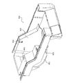
外装カバー600は、電気系統部品が設けられていない側のシャフトペーパーガイド402に設けられた切り欠き部402aを外部に開放する開口602を備えている。外装カバー600は、ハウジング101(下側ハウジング101a)に取り付けられた状態において、開口601および開口602により、切り欠き部402a、501aを外部に開放した状態で一対のシャフトペーパーガイド402、501を覆う。外装カバー600は、底部801と誘導部802とを備えている。底部801は、用紙保持部202が保持する用紙201の外径に沿った円弧状をなす。
The exterior cover 600 includes an opening 602 that opens a notch 402a provided in the shaft paper guide 402 on the side where no electrical system component is provided. The exterior cover 600 covers the pair of shaft paper guides 402 and 501 with the notches 402a and 501a open to the outside by the opening 601 and the opening 602 when attached to the housing 101 (lower housing 101a). . The exterior cover 600 includes a bottom part 801 and a guide part 802. The bottom part 801 has an arc shape along the outer diameter of the paper 201 held by the paper holding unit 202.
誘導部802は、底部801に連続し、ヘッドユニット203から用紙保持部202に向かって用紙保持部202側ほど位置が低くなるように、ボトムフレーム401に対して傾斜している。誘導部802を設けることにより、ハウジング101内に収容される用紙201が、記録動作に際してヘッドユニット203側に引っ張られた場合にも、ロールの状態のまま手前側にせり出してくることを抑制することができる。
The guiding portion 802 is continuous with the bottom portion 801 and is inclined with respect to the bottom frame 401 so that the position becomes lower toward the paper holding portion 202 from the head unit 203 toward the paper holding portion 202. By providing the guide portion 802, even when the paper 201 accommodated in the housing 101 is pulled to the head unit 203 side during the recording operation, it is prevented from protruding to the near side in the roll state. Can do.
外装カバー600は、一対のシャフトペーパーガイド402、501のうち、電気系統部品が設けられていない側のシャフトペーパーガイド402を覆う側壁部603を備えている。開口602は、側壁部603の一部を切り欠くことによって形成されている。図11および図12に示すように、外装カバー600は、プラスチック材料による射出成形などの方法により形成された一部材によって実現される。
The exterior cover 600 includes a side wall portion 603 that covers the shaft paper guide 402 on the side of the pair of shaft paper guides 402 and 501, on which the electrical system component is not provided. The opening 602 is formed by cutting out a part of the side wall portion 603. As shown in FIGS. 11 and 12, the exterior cover 600 is realized by a single member formed by a method such as injection molding using a plastic material.
以上説明したように、この発明にかかる実施の形態のプリンタ100は、略箱形状をなすハウジング101と、ハウジング101内に設けられ、記録媒体の搬送経路を間にして対向配置された一対のフレームとしてのシャフトペーパーガイド402、501と、一対のシャフトペーパーガイド402、501の上端にそれぞれ設けられた切り欠き部402a、501aと、長尺状の用紙201がロール状に巻回される巻き芯の内側に挿入された状態で切り欠き部402a、501aに両端を支持されることにより、用紙をハウジング101から引き出し可能に保持するシャフト403と、を備える。また、この実施の形態のプリンタ100は、ハウジング101内に設けられて絶縁材料を用いて形成され、切り欠き部402a、501aを外部に開放する開口601、602が設けられ、当該開口601、602を介して切り欠き部402a、501aを外部に開放した状態で一対のシャフトペーパーガイド402、501を覆う外装カバー600を備えたことを特徴としている。
As described above, the printer 100 according to the embodiment of the present invention includes a housing 101 having a substantially box shape, and a pair of frames provided in the housing 101 and arranged to face each other with a conveyance path for the recording medium therebetween. Shaft paper guides 402 and 501, as well as notch portions 402a and 501a provided at the upper ends of the pair of shaft paper guides 402 and 501, respectively, and a winding core on which the long sheet 201 is wound in a roll shape. A shaft 403 that holds the paper so that it can be pulled out of the housing 101 by being supported at both ends by the notches 402a and 501a while being inserted inside. The printer 100 according to this embodiment is provided in the housing 101 and is formed using an insulating material. The printer 100 is provided with openings 601 and 602 that open the notches 402a and 501a to the outside, and the openings 601 and 602 are provided. The exterior cover 600 which covers a pair of shaft paper guides 402 and 501 in the state which opened the notch parts 402a and 501a to the exterior via the is provided.
この発明にかかる実施の形態のプリンタ100によれば、一対のフレームとしてのシャフトペーパーガイド402、501を板金部材などの金属材料を用いて形成することにより当該一対のシャフトペーパーガイド402、501の強度を確保することができ、かつ、一対のシャフトペーパーガイド402、501を金属材料を用いて形成した場合にも、当該一対のシャフトペーパーガイド402、501に塗装処理を施すことなく、外装カバー600により一対のシャフトペーパーガイド402、501を覆うだけで、容易かつ確実に当該一対のシャフトペーパーガイド402、501を外部から絶縁することができる。これにより、大径のロール紙を保持する強度を確保したプリンタ100にかかる製造コストの低減を図ることができる。
According to the printer 100 of the embodiment of the present invention, the shaft paper guides 402 and 501 as a pair of frames are formed using a metal material such as a sheet metal member, whereby the strength of the pair of shaft paper guides 402 and 501 is increased. Even when the pair of shaft paper guides 402 and 501 is formed using a metal material, the exterior cover 600 does not perform the coating process on the pair of shaft paper guides 402 and 501. By simply covering the pair of shaft paper guides 402 and 501, the pair of shaft paper guides 402 and 501 can be insulated from the outside easily and reliably. Thereby, it is possible to reduce the manufacturing cost of the printer 100 that secures the strength to hold the large-diameter roll paper.
また、この発明にかかる実施の形態のプリンタ100によれば、外装カバー600に切り欠き部402a、501aが設けられているため、外装カバー600によって一対のシャフトペーパーガイド402、501を覆うだけで、一対のシャフトペーパーガイド402、501を外部から絶縁した状態でシャフト403の両端を一対のシャフトペーパーガイド402、501によって確実に支持する状態を、容易かつ確実に構成することができる。これにより、プリンタ100の製造工数を抑えるとともにプリンタ100の製造にかかる作業者の負担軽減を図ることができ、プリンタ100の製造にかかるコストの低減を図ることができる。
Further, according to the printer 100 of the embodiment according to the present invention, since the cutout portions 402a and 501a are provided in the exterior cover 600, only by covering the pair of shaft paper guides 402 and 501 with the exterior cover 600, A state in which both ends of the shaft 403 are reliably supported by the pair of shaft paper guides 402 and 501 with the pair of shaft paper guides 402 and 501 insulated from the outside can be easily and reliably configured. As a result, the man-hours for manufacturing the printer 100 can be reduced, the burden on the operator for manufacturing the printer 100 can be reduced, and the cost for manufacturing the printer 100 can be reduced.
また、この発明にかかる実施の形態のプリンタ100は、ハウジング101内に設けられ、プリンタ100が備える各部の駆動にかかる電気系統部品(図示を省略する制御基板および電源基板、インターフェイス基板520、中継基板530、リボン基板540、各種のケーブルなど)を備え、外装カバー600が、さらに、電気系統部品を覆うことを特徴としている。
Further, the printer 100 according to the embodiment of the present invention is provided in the housing 101, and electrical system components (a control board and a power supply board, an interface board 520, a relay board, not shown) that are used for driving each part of the printer 100 are provided. 530, ribbon substrate 540, various cables, etc.), and the exterior cover 600 further covers electrical system components.
この発明にかかる実施の形態のプリンタによれば、1つの外装カバー600をハウジング101内に装着するだけで、一対のシャフトペーパーガイド402、501および電気系統部品を覆い、一対のシャフトペーパーガイド402、501および電気系統部品を外部から絶縁することができる。これにより、プリンタ100の製造工数を抑えるとともにプリンタ100の製造にかかる作業者の負担軽減を図ることができ、プリンタ100の製造にかかるコストの低減を図ることができる。
According to the printer of the embodiment of the present invention, only by mounting one exterior cover 600 in the housing 101, the pair of shaft paper guides 402, 501 and the electric system parts are covered, and the pair of shaft paper guides 402, 501 and electrical system components can be insulated from the outside. As a result, the man-hours for manufacturing the printer 100 can be reduced, the burden on the operator for manufacturing the printer 100 can be reduced, and the cost for manufacturing the printer 100 can be reduced.
以上のように、この発明にかかるプリンタは、長尺状の用紙をロール状に巻回した用紙を記録対象とするプリンタに有用であり、特に、大型で重量のあるロール紙を記録対象とするプリンタに適している。
As described above, the printer according to the present invention is useful for a printer whose recording target is a sheet obtained by winding a long sheet in a roll shape, and particularly, a large and heavy roll paper is a recording target. Suitable for printers.
100 プリンタ
202 用紙保持部
402、501 シャフトペーパーガイド
402a、501a 切り欠き部
600 外装カバー
601、602 開口
603 側壁部
801 底部
802 誘導部 DESCRIPTION OFSYMBOLS 100 Printer 202 Paper holding part 402,501 Shaft paper guide 402a, 501a Notch part 600 Exterior cover 601,602 Opening 603 Side wall part 801 Bottom part 802 Guide part
202 用紙保持部
402、501 シャフトペーパーガイド
402a、501a 切り欠き部
600 外装カバー
601、602 開口
603 側壁部
801 底部
802 誘導部 DESCRIPTION OF
Claims (2)
- 略箱形状をなすハウジングと、
前記ハウジング内に設けられ、記録媒体の搬送経路を間にして対向配置された一対のフレームと、
前記一対のフレームの上端にそれぞれ設けられた切り欠き部と、
長尺状の用紙がロール状に巻回される巻き芯の内側に挿入された状態で前記切り欠き部に両端を支持されることにより、前記用紙を前記ハウジングから引き出し可能に保持するシャフトと、
前記ハウジング内に設けられて絶縁材料を用いて形成され、前記切り欠き部を外部に開放する開口が設けられ、当該開口を介して前記切り欠き部を外部に開放した状態で前記一対のフレームを覆う外装カバーと、
を備えたことを特徴とするプリンタ。 A substantially box-shaped housing;
A pair of frames provided in the housing and opposed to each other with a recording medium conveyance path therebetween;
Notch portions respectively provided at the upper ends of the pair of frames;
A shaft that holds the paper so that the paper can be pulled out from the housing, with both ends being supported by the notch in a state where the long paper is inserted inside a winding core wound in a roll shape,
An opening provided in the housing is formed using an insulating material, and an opening is provided to open the notch to the outside, and the pair of frames are opened with the notch being open to the outside through the opening. An outer cover to cover,
A printer comprising: - 前記ハウジング内に設けられ、前記プリンタが備える各部の駆動にかかる電気系統部品を備え、
前記外装カバーは、さらに、前記電気系統部品を覆うことを特徴とする請求項1に記載のプリンタ。 Provided in the housing, with electrical system components for driving each part of the printer,
The printer according to claim 1, wherein the exterior cover further covers the electrical system component.
Priority Applications (3)
| Application Number | Priority Date | Filing Date | Title |
|---|---|---|---|
| EP14888170.9A EP3064363B1 (en) | 2014-03-31 | 2014-12-24 | Printer |
| CN201480062607.0A CN105793053B (en) | 2014-03-31 | 2014-12-24 | Printer |
| US15/144,253 US9597907B2 (en) | 2014-03-31 | 2016-05-02 | Printer |
Applications Claiming Priority (2)
| Application Number | Priority Date | Filing Date | Title |
|---|---|---|---|
| JP2014-071554 | 2014-03-31 | ||
| JP2014071554A JP5865934B2 (en) | 2014-03-31 | 2014-03-31 | Printer |
Related Child Applications (1)
| Application Number | Title | Priority Date | Filing Date |
|---|---|---|---|
| US15/144,253 Continuation US9597907B2 (en) | 2014-03-31 | 2016-05-02 | Printer |
Publications (1)
| Publication Number | Publication Date |
|---|---|
| WO2015151360A1 true WO2015151360A1 (en) | 2015-10-08 |
Family
ID=54239717
Family Applications (1)
| Application Number | Title | Priority Date | Filing Date |
|---|---|---|---|
| PCT/JP2014/084191 WO2015151360A1 (en) | 2014-03-31 | 2014-12-24 | Printer |
Country Status (5)
| Country | Link |
|---|---|
| US (1) | US9597907B2 (en) |
| EP (1) | EP3064363B1 (en) |
| JP (1) | JP5865934B2 (en) |
| CN (1) | CN105793053B (en) |
| WO (1) | WO2015151360A1 (en) |
Families Citing this family (7)
| Publication number | Priority date | Publication date | Assignee | Title |
|---|---|---|---|---|
| JP6926397B2 (en) * | 2016-03-31 | 2021-08-25 | セイコーエプソン株式会社 | Printing equipment |
| USD832313S1 (en) * | 2016-05-09 | 2018-10-30 | Hewlett-Packard Development Company, L.P. | Three dimensional printing material container |
| USD801401S1 (en) * | 2016-05-25 | 2017-10-31 | Xerox Corporation | Printing machine |
| JP1565353S (en) * | 2016-05-25 | 2019-11-25 | ||
| GB2559404A (en) | 2017-02-06 | 2018-08-08 | Dover Europe Sarl | A printing apparatus |
| CN107244577B (en) * | 2017-08-01 | 2023-12-22 | 南通恒绮纺织有限公司 | Convenient cutting type cotton cloth structure |
| USD888822S1 (en) * | 2019-01-02 | 2020-06-30 | Ncr Corporation | Printer |
Citations (6)
| Publication number | Priority date | Publication date | Assignee | Title |
|---|---|---|---|---|
| JP2000016652A (en) * | 1998-06-30 | 2000-01-18 | Toshiba Tec Corp | Receipt printer |
| JP2001341856A (en) * | 2000-05-30 | 2001-12-11 | Canon Inc | Sheet feeder, and image forming apparatus |
| JP2002296861A (en) * | 2001-03-30 | 2002-10-09 | Ricoh Co Ltd | Dropping part catching structure and image forming device equipped therewith |
| JP2006312321A (en) * | 2006-08-01 | 2006-11-16 | Seiko Epson Corp | Printer |
| JP2008239259A (en) * | 2007-03-23 | 2008-10-09 | Max Co Ltd | Label printer |
| JP2009169126A (en) * | 2008-01-17 | 2009-07-30 | Kyocera Mita Corp | Image forming apparatus |
Family Cites Families (10)
| Publication number | Priority date | Publication date | Assignee | Title |
|---|---|---|---|---|
| KR100334212B1 (en) * | 1996-03-06 | 2002-12-02 | 세이코 엡슨 가부시키가이샤 | Paper end detector |
| JP2008284842A (en) * | 2007-05-21 | 2008-11-27 | Max Co Ltd | Label printer |
| US7967516B2 (en) * | 2008-02-25 | 2011-06-28 | Avery Dennison Corporation | Portable printer and methods |
| JP5270321B2 (en) * | 2008-12-05 | 2013-08-21 | 富士通コンポーネント株式会社 | Printer module |
| JP5293272B2 (en) * | 2009-03-02 | 2013-09-18 | セイコーエプソン株式会社 | printer |
| JP5001324B2 (en) * | 2009-03-30 | 2012-08-15 | シチズンホールディングス株式会社 | Printer |
| US8585305B2 (en) * | 2010-02-02 | 2013-11-19 | Seiko Instruments Inc. | Printer |
| JP5576138B2 (en) * | 2010-02-10 | 2014-08-20 | シチズンホールディングス株式会社 | Thermal printer |
| JP2012116572A (en) * | 2010-11-29 | 2012-06-21 | Seiko Epson Corp | Tape route maintaining mechanism, tape cartridge, and tape printer |
| JP5737574B2 (en) * | 2011-06-03 | 2015-06-17 | ブラザー工業株式会社 | Electronics |
-
2014
- 2014-03-31 JP JP2014071554A patent/JP5865934B2/en not_active Expired - Fee Related
- 2014-12-24 CN CN201480062607.0A patent/CN105793053B/en not_active Expired - Fee Related
- 2014-12-24 EP EP14888170.9A patent/EP3064363B1/en not_active Not-in-force
- 2014-12-24 WO PCT/JP2014/084191 patent/WO2015151360A1/en active Application Filing
-
2016
- 2016-05-02 US US15/144,253 patent/US9597907B2/en not_active Expired - Fee Related
Patent Citations (6)
| Publication number | Priority date | Publication date | Assignee | Title |
|---|---|---|---|---|
| JP2000016652A (en) * | 1998-06-30 | 2000-01-18 | Toshiba Tec Corp | Receipt printer |
| JP2001341856A (en) * | 2000-05-30 | 2001-12-11 | Canon Inc | Sheet feeder, and image forming apparatus |
| JP2002296861A (en) * | 2001-03-30 | 2002-10-09 | Ricoh Co Ltd | Dropping part catching structure and image forming device equipped therewith |
| JP2006312321A (en) * | 2006-08-01 | 2006-11-16 | Seiko Epson Corp | Printer |
| JP2008239259A (en) * | 2007-03-23 | 2008-10-09 | Max Co Ltd | Label printer |
| JP2009169126A (en) * | 2008-01-17 | 2009-07-30 | Kyocera Mita Corp | Image forming apparatus |
Also Published As
| Publication number | Publication date |
|---|---|
| EP3064363A1 (en) | 2016-09-07 |
| EP3064363B1 (en) | 2018-10-24 |
| JP2015193107A (en) | 2015-11-05 |
| US20160243865A1 (en) | 2016-08-25 |
| CN105793053A (en) | 2016-07-20 |
| JP5865934B2 (en) | 2016-02-17 |
| CN105793053B (en) | 2019-06-28 |
| EP3064363A4 (en) | 2017-07-19 |
| US9597907B2 (en) | 2017-03-21 |
Similar Documents
| Publication | Publication Date | Title |
|---|---|---|
| JP5865934B2 (en) | Printer | |
| JP4763577B2 (en) | Roll paper support mechanism and printer | |
| JP5857677B2 (en) | Tape printer | |
| JP5406909B2 (en) | Label printer | |
| JP4694633B2 (en) | Printing device | |
| US20170087903A1 (en) | Media transporting device and inkjet printer | |
| JP6196927B2 (en) | Printer | |
| JP2006137607A (en) | Printer and supply unit for use in printer | |
| JP2015193109A (en) | printer | |
| US9205692B2 (en) | Ink ribbon cassette and printing device | |
| JP2003341889A (en) | Paper feed magazine for recording paper roll | |
| JP6229509B2 (en) | Cutting device and printing device | |
| JP2017056708A (en) | Printer | |
| JP4824783B2 (en) | Label printer | |
| JP2015193108A (en) | printer | |
| JP4997337B2 (en) | Printing device | |
| JP2020152033A (en) | Printer and cassette set | |
| JP5286401B2 (en) | Label printer | |
| JP5576180B2 (en) | Label issuing device and printer | |
| JP7074024B2 (en) | Printing system | |
| JP2017081015A (en) | Printer | |
| JP2002002035A (en) | Printer | |
| JP2010089325A (en) | Printing apparatus | |
| JP2006272610A (en) | Printing device | |
| JP2007260992A (en) | Cartridge storing ink ribbon and printing apparatus using cartridge |
Legal Events
| Date | Code | Title | Description |
|---|---|---|---|
| 121 | Ep: the epo has been informed by wipo that ep was designated in this application |
Ref document number: 14888170 Country of ref document: EP Kind code of ref document: A1 |
|
| REEP | Request for entry into the european phase |
Ref document number: 2014888170 Country of ref document: EP |
|
| WWE | Wipo information: entry into national phase |
Ref document number: 2014888170 Country of ref document: EP |
|
| NENP | Non-entry into the national phase |
Ref country code: DE |