WO2015146828A1 - Method for manufacturing outer joint member for constant-velocity universal joint and outer joint member - Google Patents
Method for manufacturing outer joint member for constant-velocity universal joint and outer joint member Download PDFInfo
- Publication number
- WO2015146828A1 WO2015146828A1 PCT/JP2015/058482 JP2015058482W WO2015146828A1 WO 2015146828 A1 WO2015146828 A1 WO 2015146828A1 JP 2015058482 W JP2015058482 W JP 2015058482W WO 2015146828 A1 WO2015146828 A1 WO 2015146828A1
- Authority
- WO
- WIPO (PCT)
- Prior art keywords
- cup
- shaft
- cup member
- welding
- shaft member
- Prior art date
Links
Images


Classifications
-
- F—MECHANICAL ENGINEERING; LIGHTING; HEATING; WEAPONS; BLASTING
- F16—ENGINEERING ELEMENTS AND UNITS; GENERAL MEASURES FOR PRODUCING AND MAINTAINING EFFECTIVE FUNCTIONING OF MACHINES OR INSTALLATIONS; THERMAL INSULATION IN GENERAL
- F16D—COUPLINGS FOR TRANSMITTING ROTATION; CLUTCHES; BRAKES
- F16D3/00—Yielding couplings, i.e. with means permitting movement between the connected parts during the drive
- F16D3/16—Universal joints in which flexibility is produced by means of pivots or sliding or rolling connecting parts
- F16D3/20—Universal joints in which flexibility is produced by means of pivots or sliding or rolling connecting parts one coupling part entering a sleeve of the other coupling part and connected thereto by sliding or rolling members
- F16D3/22—Universal joints in which flexibility is produced by means of pivots or sliding or rolling connecting parts one coupling part entering a sleeve of the other coupling part and connected thereto by sliding or rolling members the rolling members being balls, rollers, or the like, guided in grooves or sockets in both coupling parts
-
- B—PERFORMING OPERATIONS; TRANSPORTING
- B21—MECHANICAL METAL-WORKING WITHOUT ESSENTIALLY REMOVING MATERIAL; PUNCHING METAL
- B21K—MAKING FORGED OR PRESSED METAL PRODUCTS, e.g. HORSE-SHOES, RIVETS, BOLTS OR WHEELS
- B21K1/00—Making machine elements
- B21K1/76—Making machine elements elements not mentioned in one of the preceding groups
- B21K1/762—Coupling members for conveying mechanical motion, e.g. universal joints
- B21K1/765—Outer elements of coupling members
-
- B—PERFORMING OPERATIONS; TRANSPORTING
- B23—MACHINE TOOLS; METAL-WORKING NOT OTHERWISE PROVIDED FOR
- B23K—SOLDERING OR UNSOLDERING; WELDING; CLADDING OR PLATING BY SOLDERING OR WELDING; CUTTING BY APPLYING HEAT LOCALLY, e.g. FLAME CUTTING; WORKING BY LASER BEAM
- B23K15/00—Electron-beam welding or cutting
- B23K15/0046—Welding
-
- B—PERFORMING OPERATIONS; TRANSPORTING
- B23—MACHINE TOOLS; METAL-WORKING NOT OTHERWISE PROVIDED FOR
- B23K—SOLDERING OR UNSOLDERING; WELDING; CLADDING OR PLATING BY SOLDERING OR WELDING; CUTTING BY APPLYING HEAT LOCALLY, e.g. FLAME CUTTING; WORKING BY LASER BEAM
- B23K26/00—Working by laser beam, e.g. welding, cutting or boring
- B23K26/20—Bonding
- B23K26/21—Bonding by welding
-
- B—PERFORMING OPERATIONS; TRANSPORTING
- B23—MACHINE TOOLS; METAL-WORKING NOT OTHERWISE PROVIDED FOR
- B23K—SOLDERING OR UNSOLDERING; WELDING; CLADDING OR PLATING BY SOLDERING OR WELDING; CUTTING BY APPLYING HEAT LOCALLY, e.g. FLAME CUTTING; WORKING BY LASER BEAM
- B23K31/00—Processes relevant to this subclass, specially adapted for particular articles or purposes, but not covered by only one of the preceding main groups
- B23K31/12—Processes relevant to this subclass, specially adapted for particular articles or purposes, but not covered by only one of the preceding main groups relating to investigating the properties, e.g. the weldability, of materials
- B23K31/125—Weld quality monitoring
-
- F—MECHANICAL ENGINEERING; LIGHTING; HEATING; WEAPONS; BLASTING
- F16—ENGINEERING ELEMENTS AND UNITS; GENERAL MEASURES FOR PRODUCING AND MAINTAINING EFFECTIVE FUNCTIONING OF MACHINES OR INSTALLATIONS; THERMAL INSULATION IN GENERAL
- F16D—COUPLINGS FOR TRANSMITTING ROTATION; CLUTCHES; BRAKES
- F16D1/00—Couplings for rigidly connecting two coaxial shafts or other movable machine elements
- F16D1/02—Couplings for rigidly connecting two coaxial shafts or other movable machine elements for connecting two abutting shafts or the like
- F16D1/027—Couplings for rigidly connecting two coaxial shafts or other movable machine elements for connecting two abutting shafts or the like non-disconnectable, e.g. involving gluing, welding or the like
-
- F—MECHANICAL ENGINEERING; LIGHTING; HEATING; WEAPONS; BLASTING
- F16—ENGINEERING ELEMENTS AND UNITS; GENERAL MEASURES FOR PRODUCING AND MAINTAINING EFFECTIVE FUNCTIONING OF MACHINES OR INSTALLATIONS; THERMAL INSULATION IN GENERAL
- F16D—COUPLINGS FOR TRANSMITTING ROTATION; CLUTCHES; BRAKES
- F16D1/00—Couplings for rigidly connecting two coaxial shafts or other movable machine elements
- F16D1/06—Couplings for rigidly connecting two coaxial shafts or other movable machine elements for attachment of a member on a shaft or on a shaft-end
- F16D1/064—Couplings for rigidly connecting two coaxial shafts or other movable machine elements for attachment of a member on a shaft or on a shaft-end non-disconnectable
- F16D1/068—Couplings for rigidly connecting two coaxial shafts or other movable machine elements for attachment of a member on a shaft or on a shaft-end non-disconnectable involving gluing, welding or the like
-
- F—MECHANICAL ENGINEERING; LIGHTING; HEATING; WEAPONS; BLASTING
- F16—ENGINEERING ELEMENTS AND UNITS; GENERAL MEASURES FOR PRODUCING AND MAINTAINING EFFECTIVE FUNCTIONING OF MACHINES OR INSTALLATIONS; THERMAL INSULATION IN GENERAL
- F16D—COUPLINGS FOR TRANSMITTING ROTATION; CLUTCHES; BRAKES
- F16D3/00—Yielding couplings, i.e. with means permitting movement between the connected parts during the drive
- F16D3/16—Universal joints in which flexibility is produced by means of pivots or sliding or rolling connecting parts
- F16D3/20—Universal joints in which flexibility is produced by means of pivots or sliding or rolling connecting parts one coupling part entering a sleeve of the other coupling part and connected thereto by sliding or rolling members
- F16D3/22—Universal joints in which flexibility is produced by means of pivots or sliding or rolling connecting parts one coupling part entering a sleeve of the other coupling part and connected thereto by sliding or rolling members the rolling members being balls, rollers, or the like, guided in grooves or sockets in both coupling parts
- F16D3/223—Universal joints in which flexibility is produced by means of pivots or sliding or rolling connecting parts one coupling part entering a sleeve of the other coupling part and connected thereto by sliding or rolling members the rolling members being balls, rollers, or the like, guided in grooves or sockets in both coupling parts the rolling members being guided in grooves in both coupling parts
- F16D3/226—Universal joints in which flexibility is produced by means of pivots or sliding or rolling connecting parts one coupling part entering a sleeve of the other coupling part and connected thereto by sliding or rolling members the rolling members being balls, rollers, or the like, guided in grooves or sockets in both coupling parts the rolling members being guided in grooves in both coupling parts the groove centre-lines in each coupling part lying on a cylinder co-axial with the respective coupling part
- F16D3/227—Universal joints in which flexibility is produced by means of pivots or sliding or rolling connecting parts one coupling part entering a sleeve of the other coupling part and connected thereto by sliding or rolling members the rolling members being balls, rollers, or the like, guided in grooves or sockets in both coupling parts the rolling members being guided in grooves in both coupling parts the groove centre-lines in each coupling part lying on a cylinder co-axial with the respective coupling part the joints being telescopic
-
- G—PHYSICS
- G01—MEASURING; TESTING
- G01N—INVESTIGATING OR ANALYSING MATERIALS BY DETERMINING THEIR CHEMICAL OR PHYSICAL PROPERTIES
- G01N29/00—Investigating or analysing materials by the use of ultrasonic, sonic or infrasonic waves; Visualisation of the interior of objects by transmitting ultrasonic or sonic waves through the object
- G01N29/04—Analysing solids
- G01N29/043—Analysing solids in the interior, e.g. by shear waves
-
- G—PHYSICS
- G01—MEASURING; TESTING
- G01N—INVESTIGATING OR ANALYSING MATERIALS BY DETERMINING THEIR CHEMICAL OR PHYSICAL PROPERTIES
- G01N29/00—Investigating or analysing materials by the use of ultrasonic, sonic or infrasonic waves; Visualisation of the interior of objects by transmitting ultrasonic or sonic waves through the object
- G01N29/22—Details, e.g. general constructional or apparatus details
- G01N29/28—Details, e.g. general constructional or apparatus details providing acoustic coupling, e.g. water
-
- F—MECHANICAL ENGINEERING; LIGHTING; HEATING; WEAPONS; BLASTING
- F16—ENGINEERING ELEMENTS AND UNITS; GENERAL MEASURES FOR PRODUCING AND MAINTAINING EFFECTIVE FUNCTIONING OF MACHINES OR INSTALLATIONS; THERMAL INSULATION IN GENERAL
- F16D—COUPLINGS FOR TRANSMITTING ROTATION; CLUTCHES; BRAKES
- F16D3/00—Yielding couplings, i.e. with means permitting movement between the connected parts during the drive
- F16D3/16—Universal joints in which flexibility is produced by means of pivots or sliding or rolling connecting parts
- F16D3/20—Universal joints in which flexibility is produced by means of pivots or sliding or rolling connecting parts one coupling part entering a sleeve of the other coupling part and connected thereto by sliding or rolling members
- F16D3/22—Universal joints in which flexibility is produced by means of pivots or sliding or rolling connecting parts one coupling part entering a sleeve of the other coupling part and connected thereto by sliding or rolling members the rolling members being balls, rollers, or the like, guided in grooves or sockets in both coupling parts
- F16D3/223—Universal joints in which flexibility is produced by means of pivots or sliding or rolling connecting parts one coupling part entering a sleeve of the other coupling part and connected thereto by sliding or rolling members the rolling members being balls, rollers, or the like, guided in grooves or sockets in both coupling parts the rolling members being guided in grooves in both coupling parts
- F16D2003/22326—Attachments to the outer joint member, i.e. attachments to the exterior of the outer joint member or to the shaft of the outer joint member
-
- F—MECHANICAL ENGINEERING; LIGHTING; HEATING; WEAPONS; BLASTING
- F16—ENGINEERING ELEMENTS AND UNITS; GENERAL MEASURES FOR PRODUCING AND MAINTAINING EFFECTIVE FUNCTIONING OF MACHINES OR INSTALLATIONS; THERMAL INSULATION IN GENERAL
- F16D—COUPLINGS FOR TRANSMITTING ROTATION; CLUTCHES; BRAKES
- F16D2250/00—Manufacturing; Assembly
- F16D2250/0061—Joining
- F16D2250/0076—Welding, brazing
-
- F—MECHANICAL ENGINEERING; LIGHTING; HEATING; WEAPONS; BLASTING
- F16—ENGINEERING ELEMENTS AND UNITS; GENERAL MEASURES FOR PRODUCING AND MAINTAINING EFFECTIVE FUNCTIONING OF MACHINES OR INSTALLATIONS; THERMAL INSULATION IN GENERAL
- F16D—COUPLINGS FOR TRANSMITTING ROTATION; CLUTCHES; BRAKES
- F16D3/00—Yielding couplings, i.e. with means permitting movement between the connected parts during the drive
- F16D3/16—Universal joints in which flexibility is produced by means of pivots or sliding or rolling connecting parts
- F16D3/20—Universal joints in which flexibility is produced by means of pivots or sliding or rolling connecting parts one coupling part entering a sleeve of the other coupling part and connected thereto by sliding or rolling members
- F16D3/202—Universal joints in which flexibility is produced by means of pivots or sliding or rolling connecting parts one coupling part entering a sleeve of the other coupling part and connected thereto by sliding or rolling members one coupling part having radially projecting pins, e.g. tripod joints
- F16D3/205—Universal joints in which flexibility is produced by means of pivots or sliding or rolling connecting parts one coupling part entering a sleeve of the other coupling part and connected thereto by sliding or rolling members one coupling part having radially projecting pins, e.g. tripod joints the pins extending radially outwardly from the coupling part
- F16D3/2055—Universal joints in which flexibility is produced by means of pivots or sliding or rolling connecting parts one coupling part entering a sleeve of the other coupling part and connected thereto by sliding or rolling members one coupling part having radially projecting pins, e.g. tripod joints the pins extending radially outwardly from the coupling part having three pins, i.e. true tripod joints
-
- G—PHYSICS
- G01—MEASURING; TESTING
- G01N—INVESTIGATING OR ANALYSING MATERIALS BY DETERMINING THEIR CHEMICAL OR PHYSICAL PROPERTIES
- G01N2291/00—Indexing codes associated with group G01N29/00
- G01N2291/02—Indexing codes associated with the analysed material
- G01N2291/023—Solids
- G01N2291/0234—Metals, e.g. steel
-
- G—PHYSICS
- G01—MEASURING; TESTING
- G01N—INVESTIGATING OR ANALYSING MATERIALS BY DETERMINING THEIR CHEMICAL OR PHYSICAL PROPERTIES
- G01N2291/00—Indexing codes associated with group G01N29/00
- G01N2291/26—Scanned objects
- G01N2291/262—Linear objects
- G01N2291/2626—Wires, bars, rods
-
- G—PHYSICS
- G01—MEASURING; TESTING
- G01N—INVESTIGATING OR ANALYSING MATERIALS BY DETERMINING THEIR CHEMICAL OR PHYSICAL PROPERTIES
- G01N2291/00—Indexing codes associated with group G01N29/00
- G01N2291/26—Scanned objects
- G01N2291/267—Welds
Definitions
- the present invention relates to a method for manufacturing an outer joint member of a constant velocity universal joint and an outer joint member.
- the constant velocity universal joint that constitutes the power transmission system of automobiles and various industrial machines connects the two shafts on the drive side and the driven side so that torque can be transmitted, and transmits rotational torque at a constant speed even if the two shafts have an operating angle. can do.
- Constant velocity universal joints are broadly classified into fixed constant velocity universal joints that allow only angular displacement and sliding constant velocity universal joints that allow both angular displacement and axial displacement.
- a sliding type constant velocity universal joint is used on the differential side (inboard side), and a fixed type constant velocity universal joint is used on the drive wheel side (outboard side).
- the constant velocity universal joint is composed of a cup part in which a track groove that engages a torque transmitting element is formed on the inner peripheral surface, and an axial direction from the bottom part of this cup part. And an outer joint member having an extended shaft portion.
- This outer joint member is used to integrally form the cup and shaft by subjecting a solid bar-shaped material (bar material) to plastic processing such as forging and ironing, cutting, heat treatment, grinding, etc. There are many.
- a member having a long shaft portion may be used as the outer joint member.
- the inboard side outer joint member of the drive shaft on one side is made a long stem, and this long stem is rotatably supported by a rolling bearing.
- the length of the long stem portion varies depending on the vehicle type, but is approximately 300 to 400 mm.
- the shaft portion since the shaft portion is long, it is difficult to integrally form the cup portion and the shaft portion with high accuracy. For this reason, there is a type in which the cup portion and the shaft portion are formed of separate members and both members are joined by friction welding. Such a friction welding technique is described in Patent Document 1, for example.
- the intermediate product 71 ′ of the outer joint member 71 includes a cup member 72 and a shaft member 73 and is joined by friction welding. As shown in FIG. 23, at the joining portion 74, a burr 75 is generated on at least one of the inner and outer diameters in accordance with the pressure contact.
- the burr 75 on the outer diameter side of the joint portion 74 is removed by processing such as turning as shown in FIG. There is a need.
- the intermediate product 71 ′ is a finished product of the outer joint member 71 by machining a spline, a retaining ring groove, and the like, through heat treatment, grinding, and the like. Therefore, although there is a difference in the shape of the details between the outer joint member 71 and the intermediate product 71 ′, in FIG. 24, the difference in the shape of the details is omitted for the sake of simplicity of description, and the outer side as a finished product is omitted.
- the joint member 71 and the intermediate product 71 ′ are denoted by the same reference numerals. The same applies to the following description.
- the burrs 75 of the joint 74 generated by the friction welding described above are hardened by friction heat and subsequent cooling, and have a distorted shape spreading in the radial direction and the axial direction. Therefore, as shown in FIG. 24, when the burr 75 on the outer diameter side is removed by turning, the turning tip is abraded violently due to high hardness, and the turning tip tends to be chipped due to the distorted shape. For this reason, it is difficult to increase the turning speed, and the amount of cutting per pass of the turning tip is small and the number of passes is increased. Therefore, there is a problem that the cycle time is long and the manufacturing cost is increased.
- cup member 72 and the shaft member 73 used for the friction welding shown in FIGS. 23 and 24 and the welding shown in FIG. 25 are joined at intermediate positions of shaft portions having different shapes and dimensions for each vehicle type. Therefore, as described later, it has been found that there is a problem in terms of cost reduction by improving productivity and integrating cup member types.
- the rise of the weld bead can be suppressed in laser welding and electron beam welding, so 100% inspection by ultrasonic flaw detection is possible, but it is an outer joint member of a constant velocity universal joint that is a mass-produced product for automobiles etc. We focused on improving the inspection accuracy and inspection workability of welds.
- the present invention has been proposed in view of the above-mentioned problems, and its purpose is to improve the strength and quality of the welded portion, as well as improve inspection accuracy, inspection workability, reduce welding costs, and improve productivity.
- An object of the present invention is to provide an outer joint member manufacturing method and an outer joint member that can be improved, reduce costs by integrating products, and reduce the load of production management.
- the present inventors diligently studied and verified to achieve the above object, and found the following findings. And based on these multifaceted findings, a new manufacturing concept that takes mass productivity into consideration was conceived and the present invention was achieved.
- (1) In terms of production technology, the cup member and shaft member are placed in a sealed space and evacuated, and the hollow cavity is also welded in a vacuumed state, thereby preventing the melt from blowing up and generating bubbles. It is done.
- productivity when welding a cup member and a shaft member that have been subjected to quenching and tempering heat treatment in order to improve productivity, the temperature of the peripheral portion increases due to heat during welding, and the heat treatment portion There is a concern that the hardness of the steel will decrease.
- the cup member 72 shown in FIGS. 23 to 25 has the following problems.
- the cup member 72 is formed with a short shaft portion whose diameter is reduced from the bottom portion of the cup portion by forging or the like.
- the short shaft portion is set based on the shape and dimensions of the shaft member 73, and the shaft portion It is the structure joined in the middle position.
- the shaft member 73 is required to have various shaft diameters and outer peripheral shapes in addition to the standard length stem and long stem type depending on the vehicle to be assembled. For this reason, when the short shaft portion of the cup member 72 is set with reference to the shape and dimensions of the shaft member 73 and joined at an intermediate position of the shaft portion 73, the short shaft portion of the cup member 72 joined to the shaft member 73 Since both the shaft diameter (joining diameter), shape, and length (joining position) are different, a dedicated cup member 72 is required for one kind of shaft member 73.
- the present invention separates a cup portion formed on the inner periphery with a track groove engaged with a torque transmitting element and a shaft portion formed on the bottom portion of the cup portion.
- the cup member and the shaft member are made of medium carbon
- the cup member is prepared by forming a joining end face on the outer surface of the bottom part in the machining step, and the shaft member.
- the joining end face of the cup member and the joining end face of the shaft member are abutted, and the abutting portion is Mosquito
- the outer diameter of the joint member is irradiated with a beam in the radial direction, and the outer diameter of the joint end surface of the cup member is the same for each joint size, and the joint member end surface of the cup member and the shaft member is welded.
- a protruding surface protruding radially inward from the inner diameter of the other joining end face is provided on the inner diameter side of one joining end face, and after welding in this state, the surface side of the member having the other joining end face It comprises an ultrasonic flaw detection inspection process for flaw detection.
- the present invention as an outer joint member of a constant velocity universal joint includes a cup part formed on the inner periphery of a track groove with which a torque transmission element engages and a shaft part formed on the bottom part of the cup part as separate members.
- the cup member and the shaft member are made of medium carbon steel
- a cylindrical portion and a bottom portion are integrally formed by forging, and a joining end surface is formed on an outer surface of the bottom portion.
- the shaft member is joined to an end portion to be joined to the bottom portion.
- the outer diameter of the joining end face of the cup member is set to the same dimension for each joint size, and the inner diameter side of one joining end face of the joining end faces of the cup member and the shaft member is larger than the inner diameter of the other joining end face.
- a projecting surface projecting radially inward is provided and welded in this state.
- the ultrasonic flaw detection inspection process it is preferable to place the welded cup member and shaft member in water and perform flaw detection. Thereby, inspection accuracy can be further improved.
- the degree of processing of the cup member to be integrated is improved, and productivity is improved and production control is reduced. It can be further promoted. Moreover, since ultrasonic waves can be incident from the surface side of the shaft member having a small shaft diameter by the oblique probe at the time of ultrasonic flaw inspection of the welded portion, flaw detection inspection can be facilitated.
- the outer diameter of the joining end surface of the cup member is the same for each joint size, or the protruding surface is the same for each joint size,
- One joint size is not limited to one type, that is, one part number.
- multiple types (multiple part numbers) of cup members are set with one joint size according to different specifications of the maximum operating angle, These cup members have a concept of wrapping those having the same outer diameter of the joining end faces and those having the same protruding surfaces.
- a plurality of types (multiple product numbers) of cup members are set with one joint size, and the outer diameters of the end surfaces for joining of these cup members are the same size, and those with the same protruding surface are also included. .
- the fact that the outer diameter of the joining end face of the cup member is the same for each joint size, and the protruding face is the same for each joint size For example, on the inboard side, the outer diameter of the end surface for joining of the tripod type constant velocity universal joint and the double offset type constant velocity universal joint is made the same dimension and the protruding surface is On the outboard side, the outer diameter of the end face for joining of the Rzeppa type constant velocity universal joint and the undercut free type constant velocity universal joint is set to the same size, and the protruding surface is set to be the same. It is a concept that includes things. Furthermore, it is possible to make the outer diameters of the joint end faces of the constant velocity universal joints on the inboard side and the outboard side the same, and to set the protruding surfaces to be the same.
- At least one of the cup member and the shaft member before welding can be an intermediate part that is not subjected to heat treatment.
- finish processing such as heat treatment, grinding, and hardened steel cutting is performed. It is suitable for cup members and shaft members having shapes and specifications that affect the hardness of the heat-treated portion because the temperature at the periphery increases due to the heat during welding. Part numbers are assigned to the above intermediate parts for management.
- At least one of the cup member and the shaft member before welding can be a finished part subjected to heat treatment. Finished parts such as heat treatment and post-heat treatment grinding and hardened steel cutting, etc., so that the finished cup parts can be shared for each joint size and various shaft specifications for each vehicle type Since the shaft member provided with is obtained, the product number can be assigned and managed. Therefore, the cost reduction and the production management load reduction due to the integration of the cup member types become remarkable.
- the common cup member and the shaft member with various shaft specifications can be used separately for finished parts such as forging, turning, heat treatment, and finishing such as grinding and hardened steel cutting. The productivity is improved, including the reduction of setup.
- the cup member and shaft member as a finished part are not limited to those subjected to the finishing processing such as grinding and quenching steel cutting after the heat treatment described above.
- the concept includes a member and a shaft member.
- the hardness of the welded portion between the cup member and the shaft member is preferably in the range of Hv 200 to 500. If it is less than Hv200, it is difficult to ensure the strength required for the product function, which is not desirable. On the other hand, if it exceeds Hv500, it is not desirable because cracks associated with phase transformation and a decrease in fatigue strength due to changes in toughness may occur.
- the strength of the welded portion, the improvement of quality, the reduction of the welding cost, the inspection accuracy of the welded portion and the improvement of the inspection workability can be realized.
- FIG. 2b shows the whole structure of the drive shaft to which 1st Embodiment is applied about the outer joint member which concerns on this invention. It is a fragmentary longitudinal cross-sectional view which expands and shows the outer joint member of FIG. 2b is an enlarged view of the weld of FIG. 2a. FIG. It is an enlarged view which shows the shape before welding of FIG. 2b. It is a schematic diagram which shows the manufacturing process of the outer joint member of FIG. The cup member before welding is shown and it is a longitudinal section of the cup member after ironing. The cup member before welding is shown, and is a longitudinal sectional view of the cup member after turning. It shows a shaft member before welding, and is a front view of a bar material as a material.
- the shaft member before welding is shown, and is a partial longitudinal sectional view of the shaft member after forging.
- the shaft member before welding is shown, and is a partial longitudinal cross-sectional view after turning and spline processing.
- FIG. 11 is a partial enlarged view taken along the line FF in FIG.
- FIG. 11 is a partial enlarged view taken along the line FF in FIG. 10 and showing a defective weld product. It is a figure which shows the knowledge in a development process. It is a front view which shows the shaft member from which a product number differs. It is a fragmentary longitudinal cross-section which shows the outer joint member manufactured using the shaft member of FIG. It is a figure which shows the example of the kind integration of a cup member. It is a fragmentary longitudinal cross-section which shows the modification of the outer joint member of 1st Embodiment. It is an enlarged view of the weld part of FIG. 17a. It is an enlarged view which shows the shape before welding of FIG.
- FIGS. 1 and 2 show a first embodiment of the outer joint member according to the present invention. Shown in First, a first embodiment of an outer joint member will be described with reference to FIGS. 1 and 2, and then a first embodiment of a method for manufacturing an outer joint member will be described with reference to FIGS. .
- FIG. 1 is a diagram showing an overall structure of a drive shaft 1 in which the outer joint member 11 of the first embodiment is used.
- the drive shaft 1 includes a sliding type constant velocity universal joint 10 disposed on the differential side (right side in the figure: hereinafter also referred to as inboard side) and a drive wheel side (left side in the figure: hereinafter also referred to as outboard side).
- the fixed type constant velocity universal joint 20 and the intermediate shaft 2 that couples the two constant velocity universal joints 10 and 20 so as to transmit torque are the main components.
- a sliding type constant velocity universal joint 10 shown in FIG. 1 is a so-called double offset type constant velocity universal joint (DOJ).
- the constant velocity universal joint 10 includes an outer joint member 11 having a cup portion 12 and a long shaft portion (hereinafter, also referred to as a long stem portion) 13 extending in the axial direction from the bottom portion of the cup portion 12, and an outer joint member 11.
- a cylindrical inner peripheral surface 42 of the member 11 and a spherical outer peripheral surface 43 of the inner joint member 16 are fitted with a spherical outer peripheral surface 45 and a spherical inner peripheral surface 46, respectively, and a cage 44 holding the ball 41.
- the center of curvature O 1 of the spherical outer peripheral surface 45 of the cage 44 and the center of curvature O 2 of the spherical inner peripheral surface 46 are offset from the joint center O by the same distance on the opposite side in the axial direction.
- the inner ring of the support bearing 6 is fixed to the outer peripheral surface of the long stem portion 13, and the outer ring of the support bearing 6 is fixed to the transmission case via a bracket (not shown).
- the outer joint member 11 is rotatably supported by the support bearing 6, and by providing such a support bearing 6, the outer joint member 11 is prevented from swinging during operation or the like as much as possible.
- a fixed type constant velocity universal joint 20 shown in FIG. 1 is a so-called Rzeppa type constant velocity universal joint, and has an outer side having a bottomed cylindrical cup portion 21a and a shaft portion 21b extending in the axial direction from the bottom portion of the cup portion 21a.
- a torque transmission element disposed between the joint member 21, the inner joint member 22 accommodated in the inner periphery of the cup portion 21 a of the outer joint member 21, and the cup portion 21 a and the inner joint member 22 of the outer joint member 21.
- a cage 24 that is disposed between the inner peripheral surface of the cup portion 21 a of the outer joint member 21 and the outer peripheral surface of the inner joint member 22 and holds the ball 23.
- An undercut-free type constant velocity universal joint may be used as the fixed type constant velocity universal joint 20.
- the intermediate shaft 2 has torque transmission splines (including serrations; the same applies hereinafter) 3 at the outer diameters at both ends. Then, the spline 3 on the inboard side is spline-fitted with the hole portion of the inner joint member 16 of the sliding type constant velocity universal joint 10, whereby the inner joint member 16 of the intermediate shaft 2 and the sliding type constant velocity universal joint 10. Are coupled so that torque can be transmitted. Further, the spline 3 on the outboard side is spline-fitted with the hole of the inner joint member 22 of the fixed type constant velocity universal joint 20, so that the intermediate shaft 2 and the inner joint member 22 of the fixed type constant velocity universal joint 20 are connected. Connected to transmit torque. As the intermediate shaft 2, a solid type is shown, but a hollow type can also be used.
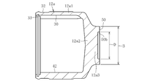
- FIG. 2 is an enlarged view of the outer joint member 11 of the present embodiment.
- FIG. 2a is a partial longitudinal sectional view
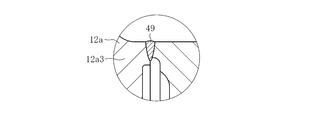
- FIG. 2b is an enlarged view of a portion A in FIG. 2a
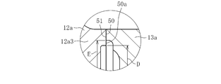
- FIG. It is a figure which shows a shape.
- the outer joint member 11 is open at one end, and has a bottom with a plurality of track grooves 30 and a cylindrical inner peripheral surface 42 on which balls 41 (see FIG. 1) roll at equal intervals in the circumferential direction of the inner peripheral surface.
- the outer joint member 11 is formed by welding a cup member 12a and a shaft member 13a.
- the cup member 12a shown in FIGS. 2a to 2c is made of medium carbon steel containing 0.40 to 0.60% by weight of carbon such as S53C, and has a track groove 30 and a cylindrical inner peripheral surface 42 formed on the inner periphery. It is an integrally molded product comprising a cylindrical portion 12a1 and a bottom portion 12a2. A convex portion 12a3 is formed on the bottom portion 12a2 of the cup member 12a.
- a boot mounting groove 32 is formed on the outer periphery on the opening side of the cup member 12a, and a retaining ring groove 33 is formed on the inner periphery.
- the shaft member 13a has a bearing mounting surface 14 and a retaining ring groove 15 formed on the outer periphery on the cup member 12a side, and a spline Sp formed on the opposite end.
- the shaft member 13a is made of medium carbon steel containing 0.30 to 0.55 wt% carbon such as S40C.
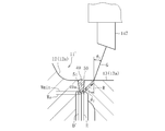
- the joining end surface 50 formed on the convex portion 12a3 of the bottom 12a2 of the cup member 12a and the joining end surface 51 at the end of the shaft member 13a on the side of the cup member 12a are abutted, and electron beam welding is performed radially from the outside of the cup member 12a. It is welded by.
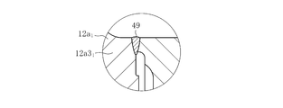
- the welded portion 49 is formed by a bead of a beam irradiated from the radially outer side of the cup member 12a.
- the outer diameter B see FIGS.
- the outer diameter B of the joining end face 50 of the cup member 12a and the outer diameter B of the joining end face 51 of the shaft member 13a are not necessarily the same size.
- An appropriate dimensional difference such as slightly reducing the outer diameter B of the bonding end surface 51 from the outer diameter B of the bonding end surface 50 may be provided (the outer diameter B of the bonding end surface 50 and the bonding end surface 51
- the dimensional relationship with the outer diameter B is the same in this specification).
- the bearing mounting surface 14 and the like can be processed in advance, and post-processing after welding can be eliminated. Further, since burrs do not appear in the weld due to electron beam welding, post-processing of the weld can be omitted, and the manufacturing cost can be reduced. Further, 100% inspection by ultrasonic flaw detection of the welded portion is possible.
- ultrasonic waves that can improve the inspection accuracy and inspection workability of the welded portion. It is characterized by a flaw detection method and weld shape. Details will be described later.
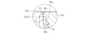
- the inner diameter D of the joining end surface 50 of the cup member 12a is set smaller than the inner diameter E of the joining end surface 51 of the shaft member 13a.
- a protruding surface 50a is provided that protrudes radially inward from the inner diameter E of the joining end surface 51. In this state, the cup member 12a and the shaft member 13a are welded.
- the protruding surface 50a is set to be the same for each joint size.
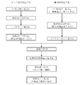
- FIG. 3 shows an outline of the manufacturing process of the outer joint member.
- the cup member 12a is manufactured by a manufacturing process including a bar material cutting process S1c, a forging process S2c, an ironing process S3c, and a turning process S4c, as shown.
- the shaft member 13a is manufactured by a manufacturing process including a bar material cutting process S1s, a turning process S2s, and a spline processing process S3s.
- the intermediate parts of the cup member 12a and the shaft member 13a manufactured in this way are each assigned a product number and managed.
- the outer joint member 11 is completed after the cup member 12a and the shaft member 13a have undergone the welding step S6, the ultrasonic flaw detection inspection step S6k, the heat treatment step S7, and the grinding step S8.
- the machining process in the claims means a turning process S4c, a turning process S2s, and a grinding process S5s (see FIG. 20) described later, among the above manufacturing processes.
- Bar material cutting step S1c Based on the forging weight, the bar material is cut at a predetermined length to produce a billet.
- Forming process S2c The billet is forged, and the cylindrical part, the bottom part, and the convex part are integrally formed as a shape material of the cup member 12a.
- the manufacturing process of the shaft member 13a will be described.
- Bar material cutting process S1s Based on the total length of the shaft part, the bar material is cut at a predetermined length to produce a billet. Thereafter, depending on the shape of the shaft member 13a, the billet may be forged into an approximate shape by upset forging.
- Induction hardening and tempering are performed as heat treatment on at least the track grooves 30, the cylindrical inner peripheral surface 42 and the outer periphery of the shaft portion 13 of the cup portion 12 after welding. The weld is not heat treated.
- a hardened layer of about HRC 58 to 62 is formed on the track groove 30 and the cylindrical inner peripheral surface 42 of the cup portion 12. Further, a hardened layer of about HRC 50 to 62 is formed in a predetermined range on the outer periphery of the shaft portion 13.
- the heat treatment process is incorporated after the welding process, the temperature of the peripheral part rises due to the heat during welding, and the cup member and shaft having a shape and specifications that affect the hardness of the heat treatment part. Suitable for parts.
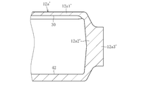
- FIG. 4a is a longitudinal sectional view showing a state after the ironing of the cup member 12a
- FIG. 4b is a longitudinal sectional view showing a state after the turning.
- the cylindrical portion 12a1', the bottom portion 12a2 'and the convex portion 12a3' are integrally formed in the forging step S2c.
- the track grooves 30 and the cylindrical cylindrical surface 42 are ironed, and the inner periphery of the cylindrical portion 12a1 'is finished as shown in FIG. 4a.
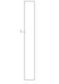
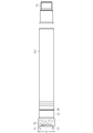
- FIG. 5 shows a state in each processing step of the shaft member 13a.
- FIG. 5 a is a front view showing a billet 13 a ′′ obtained by cutting a bar material
- FIG. 5 b is a partial longitudinal sectional view showing a raw material 13 a ′ obtained by forging the billet 13 a ′′ into an approximate shape by upset forging
- FIG. It is a fragmentary longitudinal cross-section which shows the shaft member 13a after a turning process and a spline process.
- the billet 13a "shown in FIG. 5a is manufactured. If necessary, the billet 13a" is expanded by upset forging as shown in FIG. A shaped member 13a ′ having a recess 52 formed on the side end (the end on the cup member 12a side) is manufactured.
- the outer diameter of the shaft member 13a, the bearing mounting surface 14, the retaining ring groove 15, the inner diameter portion 53 (inner diameter E) of the recess 52, the end face 51 for joining and the outside thereof The diameter B is turned, and in the spline processing step S3s, the spline Sp is processed at the opposite end of the recess 52 by rolling or pressing.
- the outer diameter B of the joining end surface 50 of the convex portion 12a3 of the bottom portion 12a2 of the cup member 12a shown in FIG. 4b is set to be the same size with one joint size.
- the shaft member 13a shown in FIG. 5c is for a long stem, the outer diameter B of the joining end surface 51 at the end on the cup member 12a side is not related to the shaft diameter or the outer peripheral shape of the cup member 12a. It is set to the same dimension as the outer diameter B of the joining end face 50.
- the joining end surface 51 of the shaft member 13 a is set at a position closer to the cup member 12 a than the bearing mounting surface 14.
- the cup member 12a is shared, only the shaft member 13a is manufactured in various shaft diameters, lengths and outer peripheral shapes according to the vehicle type, and both the members 12a and 13a are welded.
- the outer joint member 11 suitable for various vehicle types can be manufactured. Details of sharing the cup member 12a will be described later.
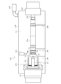
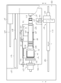
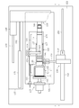
- FIGS. 6 and 7 are schematic views showing the welding apparatus.
- FIG. 6 shows a state before welding
- FIG. 7 shows a state where welding is performed.
- the welding apparatus 100 includes an electron gun 101, a rotating device 102, a chuck 103, a center hole guide 104, a tail stock 105, a work cradle 106, a center hole guide 107, a case 108, and a vacuum pump 109.
- the configuration is shown in FIG. 6, the welding apparatus 100 includes an electron gun 101, a rotating device 102, a chuck 103, a center hole guide 104, a tail stock 105, a work cradle 106, a center hole guide 107, a case 108, and a vacuum pump 109.
- the configuration is shown in FIG. 6, the welding apparatus 100 includes an electron gun 101, a rotating device 102, a chuck 103, a center hole guide 104, a tail stock 105, a work cradle 106, a
- the cup member 12a and the shaft member 13a which are workpieces, are placed on the workpiece cradle 106 in the welding apparatus 100.
- the chuck 103 and the centering jig 107 at one end of the welding device 100 are connected to the rotating device 102, and the cup member 12a is gripped by the chuck 103 in a state where the cup member 12a is centered by the center hole guide 107, and rotational motion is performed.
- a center hole guide 104 is integrally attached to a tail stock 105 at the other end of the welding apparatus 100, and both are configured to be able to advance and retract in the axial direction (left and right direction in FIG. 7).
- the center hole of the shaft member 13a is set in the center hole guide 104 and is centered.
- a vacuum pump 109 is connected to the case 108 of the welding apparatus 100.
- the sealed space means a space 111 formed by the case 108.
- the entire cup member 12 a and the shaft member 13 a are accommodated in the sealed space 111.
- An electron gun 101 is provided at a position corresponding to the joining end faces 50 and 51 of the cup member 12a and the shaft member 13a. The electron gun 101 is configured to be close to a predetermined position with respect to the workpiece.
- the cup member 12a and the shaft member 13a which are workpieces, are stocked at a place different from the welding apparatus 100.
- Each workpiece is taken out by, for example, a robot, conveyed into the case 108 of the welding apparatus 100 opened to the atmosphere shown in FIG. 6, and set at a predetermined position of the workpiece cradle 106.
- the center hole guide 104 and the tail stock 105 are retracted to the right in the drawing, and a gap is provided between the joining end surfaces 50 and 51 of the cup member 12a and the shaft member 13a.
- the door (not shown) of the case 108 is closed, and the vacuum pump 109 is activated to depressurize the sealed space 111 formed in the case 108.
- the inside diameter part 50b of the cup member 12a, the recessed part 52 of the shaft member 13a, and the inside of the inside diameter part 53 are also decompressed.
- the center hole guide 104 and the tail stock 105 move forward to the left, and the gap between the end surfaces 50 and 51 for joining the cup member 12a and the shaft member 13a is formed. Disappear. Thereby, the cup member 12 a is centered by the center hole guide 107 and fixed by the chuck 103, and the shaft member 13 a is supported by the center hole guide 104. Thereafter, the work cradle 106 moves away from the work. At this time, the interval between the workpiece cradle 106 and the workpiece may be very small, and thus the interval is not shown in FIG. Of course, it is possible to have a structure in which the workpiece cradle 106 is largely retracted downward.
- the electron gun 101 approaches the work to a predetermined position, rotates the work, and starts preheating.
- the preheating condition is set to a temperature lower than the welding temperature by, for example, irradiating the electron gun 101 close to the workpiece and irradiating the electron beam with a large spot diameter. By preheating, burning cracks can be prevented by slowing the cooling rate after welding.
- the electron gun 101 is retracted to a predetermined position, and an electron beam is irradiated in the radial direction from the outside of the workpiece to start welding.
- the electron gun 101 is retracted and the rotation of the workpiece is stopped.
- the sealed space 111 is opened to the atmosphere. Then, with the workpiece cradle 106 raised and supporting the workpiece, the center hole guide 104 and the tail stock 105 are retracted to the right, and the chuck 103 is released. Thereafter, for example, the robot grabs the workpiece, removes it from the welding apparatus 100, and aligns it with the cooling stocker.
- the configuration of the sealed space 111 in the case 108 can be simplified.
- the above-described welding apparatus 100 uses the cup member 12a.
- the pressure in the sealed space 111 was set to 6.7 Pa or less for welding.
- Electron beam welding was performed. As a result, a welded portion having a raised height (0.5 mm or less) on the weld surface that does not affect the product function was obtained.
- the weld zone hardness after completion of welding could be suppressed within the range of Hv 200 to 500, and the welding strength was high and stable welding condition and quality could be obtained. Furthermore, by welding the sealed space 111 of the welding apparatus 100 at atmospheric pressure or lower, it is possible to suppress a pressure change in the hollow cavity during welding, and to prevent the melt from being blown up or drawn into the inner diameter side. did it.
- FIG. 8 is a front view showing an outline of the ultrasonic flaw detection apparatus as viewed in the direction of arrows GG in FIG. 9, and FIG. 9 is a plan view. Shows a state of being placed on FIG. 10 is a front view showing a state under examination as viewed from the line HH in FIG. 11, and FIG. 11 is a plan view.
- the ultrasonic flaw detection apparatus 120 includes a water storage tank 122, a work receiving base 123, a work holding member 124, and an intermediate product 11 ′ of the outer joint member 11 installed at the center of the base 121.
- a rotation driving device 125 that rotates hereinafter also referred to as a workpiece 11 ′
- a pressing device 135 that presses the shaft end of the workpiece 11 ′
- a probe drive positioning device 136 are mainly configured.
- the work cradle 123 is provided with rollers 126 and 127 for placing the work 11 'rotatably.
- the rollers 126 and 127 are provided in pairs so that the shaft portion 13 of the workpiece 11 ′ can be stably supported.
- the rollers 126 are located near the welded portion, and the roller 127 has a shaft.
- the rollers 126 and 127 are appropriately installed in the axial direction (left-right direction in FIG. 9) and radial direction (up-down direction in FIG. 9) of the work 11 ′. It can be adjusted.
- the workpiece holder 123 is provided with a workpiece pressing member 124 at a position off the plane from the axis of the workpiece 11 '(see FIG. 9).
- the work pressing member 124 has a lever 128, and a work pressing roller 129 is provided at the end of the lever 128.
- the lever 128 can turn on a plane and can move up and down.
- the work cradle 123 is attached to the support pedestal 134 via a linear motion bearing 130 including a rail 131 and a linear guide 132, and is movable in the axial direction (left and right direction in FIGS. 8 and 9).
- the support base 134 is attached to the base 121.
- a rod 133 is connected to the end of the work cradle 123 (the left end in FIGS. 8 and 9), and is driven and positioned from the outside of the water storage tank 122 by an actuator (not shown).
- the rotation driving device 125 has a rotating shaft 143 provided with a rotating plate 144, and the rotating shaft 143 is rotationally driven from the outside of the water storage tank 122 by a motor (not shown).
- a gantry 137 is provided on the upper side of the ultrasonic inspection device 120, and a substrate 145 of a pressing device 135 that presses the shaft end of the work 11 ′ is a linear motion bearing 138 including a rail 139 and a linear guide 140. It is attached to the gantry 137 via and is movable in the axial direction (left and right direction in FIGS. 8 and 9).
- the rod 142 of the air cylinder 141 is connected to the end of the substrate 145 of the pressing device 135 and driven.
- a free bearing 146 is attached to a portion of the workpiece 11 ′ that comes into contact with the shaft end of the shaft portion 13 so that the workpiece 11 ′ can be pressed freely.
- a probe drive positioning device 136 is disposed at a position deviated on the plane from the axis of the workpiece 11 ′.
- the drive positioning device 136 includes actuators in the X-axis direction (left-right direction in FIG. 9) and Y-axis direction (up-down direction in FIG. 9), and the probe 147 is driven and positioned in the XY-axis direction.
- the actuator 148 in the X-axis direction and the actuator 149 in the Y-axis direction are electric ball screw types (robo cylinders) and can be positioned with high accuracy.
- Reference numeral 150 denotes a rail of a linear motion bearing.
- the drive positioning device 136 is disposed outside the water storage tank 122, and the probe 147 and its holder 151 are disposed in the water storage tank 122.
- the ultrasonic flaw detection inspection process S6k will be described together with the operation of the ultrasonic flaw detection inspection apparatus 120.
- the welded work 11 ′ is placed on the work cradle 123 by a loader (not shown).
- the workpiece cradle 123 is positioned at an appropriate interval in the axial direction of the workpiece 11 ′ from the rotation driving device 125, and the workpiece pressing member 124 raises the lever 128.
- it is swung so as to be substantially parallel to the axis of the workpiece 11 ′.
- the pressing device 135 and the probe drive positioning device 136 are on standby at the retracted position.
- the ultrasonic flaw detection inspection apparatus 120 is configured to detect flaws in water, so that the propagation of ultrasonic waves is good and high-accuracy inspection is possible.
- the air cylinder 141 is driven to advance the pressing device 135 to press the shaft end of the workpiece 11 ′, and the opening end of the cup portion 12 of the workpiece 11 ′ is rotated to the rotational driving device 125.
- the pressing device 135 advances, the work cradle 123 also moves toward the rotation drive device 125.
- the workpiece 11 ' is positioned in the radial direction and the axial direction.
- a motor (not shown) of the rotation driving device 125 rotates, and the workpiece 11 'rotates.
- the drive positioning device 136 moves in the X-axis direction and further in the Y-axis direction, and the probe 147 is positioned at the flaw detection position (the probe 147 in this state is shown in FIG. 10). (Shown with a dashed line). Then, a flaw detection inspection is performed. When the flaw detection inspection is completed, the workpiece 11 'is drained and the work 11' is discharged from the ultrasonic flaw detector 120 by a loader (not shown). In this manner, the inspection of the workpiece 11 'is sequentially repeated.
- ultrasonic flaw detection inspection apparatus 120 of the present embodiment in order to shorten the inspection cycle time, time-consuming water supply and drainage are performed at interlocked timings such as simultaneous operation of each apparatus and member.
- time-consuming water supply and drainage are performed at interlocked timings such as simultaneous operation of each apparatus and member.
- the operations of the respective devices and members can be appropriately implemented by partially performing simultaneous operations or changing the order of parts.
- FIGS. 12a, 12b and 13 Details of the ultrasonic flaw detection inspection will be described with reference to FIGS. 12a, 12b and 13.
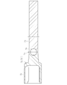
- FIG. 12a shows a good weld product
- FIG. 12b shows a poor weld product.
- FIG. 13 shows the findings in the development process.
- the probe 147 is positioned at a flaw detection position at a predetermined distance from the welded portion 49.
- the flaw detection position is preset for each joint size.
- the welding target depth is indicated by Wa
- the welding pass / fail depth is indicated by Wmin.
- the welding pass / fail depth Wmin or more is determined as a good welding product
- the welding pass / fail depth Wmin is determined as a poor welding product.
- the probe 147 positioned at the flaw detection position at a predetermined distance from the welded portion 49 collects data of the entire circumference of the workpiece 11 '. Specifically, in order to cope with the deviation of the welding position of the welding position, first, data of one rotation (360 °) of the workpiece 11 ′ is collected at the above-described flaw detection position, and then sequentially, a minute pitch (for example, 0.5 mm), and data for a plurality of rotations (for example, 5 rotations) is collected. The acceptance / rejection determination is made based on this data, and the threshold value of the reflection echo for the acceptance / rejection determination is determined using a welding example of the welding acceptance / rejection depth Wmin.
- the inner diameter D of the joining end surface 50 of the cup member 12a is set smaller than the inner diameter E of the joining end surface 51 of the shaft member 13a, and the joining of the shaft member 13a is performed on the joining end surface 50 of the cup member 12a.
- a protruding surface 50 a is provided that protrudes radially inward from the inner diameter E of the end surface 51 for use. In this state, the cup member 12a and the shaft member 13a are welded.
- the height of the reflected echo received by the probe 147 is equal to or less than the threshold value, and is determined as a good welding product.
- FIG. 13 shows the findings in the development process that led to the idea of the shape of the welded portion of the present embodiment.
- the inner diameter D 'of the joining end face 50 of the cup member 12a and the inner diameter E of the joining end face 51 of the shaft member 13a are made the same size.
- the welding depth is a welding good product having a welding pass / fail depth Wmin or more, when a transmission pulse G is incident from the probe 147, a boundary surface in the direction perpendicular to the transmission pulse G exists on the back surface bead 49a.
- the probe 147 receives the reflected echo R reflected by this boundary surface.
- the reflection echo of the back surface bead 49a is scattered, the reflection echo R is high, so that it becomes equal to or greater than the threshold value of the reflection echo in the pass / fail determination, and it is determined that the weld is defective. Because of this situation, it has been found that it is difficult to determine whether the welded product is good or defective. Based on this knowledge, it came to conceive the welded part shape of this embodiment.
- the height Q
- a relationship of S ⁇ Q is established. With this relationship, the height of the reflected echo can be clearly distinguished, so that a good weld product and a defective product can be accurately determined. If the relationship of S ⁇ Q is maintained, the dimension of the projecting surface 50a can be set as appropriate.
- the ultrasonic flaw detection inspection apparatus 120 has the water storage tank 122 installed at the center of the base 121, and the work receiving base 123, the work pressing member 124, and the work 11 ′ arranged therein.
- the main components are the rotating plate 144 of the rotary drive device 125 to be rotated, the free bearing 146 of the pressing device 135 that presses the shaft end of the workpiece 11 ′, and the probe 147 attached to the drive positioning device 136.
- the outer joint member having a different product number is combined with the base structure in which the outer diameter B of the joining end surface 50 of the cup member 12a of the present embodiment is the same for each joint size. 11 can be reduced, and the inspection efficiency can be further improved.
- the propagation of ultrasonic waves is good, and it is possible to perform inspection with higher accuracy.
- the shape of the welded portion in which the projecting surface 50a is provided on the joining end surface 50 is adopted, the height of the reflection echo can be clearly distinguished, and a good weld product and a defective product can be accurately determined. .
- the shaft member 13b shown in FIGS. 14 and 15 is for a standard stem on the inboard side.
- the shaft member 13b is formed with a joining end surface 51 that abuts the joining end surface 50 (see FIG. 4b) of the bottom 12a2 (projection 12a3) of the cup member 12a.
- the outer diameter B and inner diameter E of the joining end surface 51 are formed to have the same dimensions as the outer diameter B and inner diameter E of the joining end surface 51 of the long stem type shaft member 13a shown in FIG.
- the inner diameter D of the joining end face 50 of the cup member 12a is set smaller than the inner diameter E of the joining end face 51 of the shaft member 13b, and the joining end face 50 of the cup member 12a is connected to the joining end face 50 of the shaft member 13b.
- a protruding surface 50 a that protrudes radially inward from the inner diameter E of the end surface 51 is provided. In this state, the cup member 12a and the shaft member 13b are welded.
- this shaft member 13b is for a standard stem on the inboard side, the length of the shaft portion is short, and a sliding bearing surface 18 is formed in the central portion in the axial direction, and a plurality of oil grooves 19 are formed on this sliding bearing surface 18. Is formed. A spline Sp and a retaining ring groove 48 are formed at the end opposite to the cup member 12a side.
- the outer diameter B of the joining end face 51 of the shaft members 13a and 13b is different even if the stem length or the long stem of the standard length is different, or the various shaft diameters or outer peripheral shapes are different for each vehicle type. The same dimensions are set.
- the outer diameter B of the joining end surfaces 50 and 51 of the cup member 12a and the shaft members 13a and 13b is set to the same dimension for each joint size, there are various cup members and vehicle types that are shared for each joint size.
- a shaft member having a shaft specification can be prepared in a state before the heat treatment, and a product number can be assigned to each of the intermediate parts of the cup member 12a and the shaft members 13a and 13b for management.
- cup members In the above, for the sake of easy understanding, the type integration of cup members has been explained by taking the difference between the standard length stem and the long stem as an example, but the standard length is not limited to this. This also applies to the integration of cup members with respect to shaft members having various shaft specifications for each vehicle type between the stems and shaft members having various shaft specifications for each vehicle type between the long stems.
- the cup member is shared by one joint size, and is managed with, for example, a product number C001.
- the shaft member has various shaft part specifications for each vehicle type, and is managed by being assigned product numbers S001, S002, to S (n), for example.
- the integration of the cup member types can reduce the cost and the production management load.
- the cup member is not limited to one type with one joint size, that is, one model number. For example, a plurality of types (multiple types with one joint size according to specifications with different maximum operating angles). No.) cup members are set, and those having the same outer diameter B of the joining end faces of these cup members are wrapped.
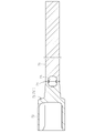
- FIG. 17 and FIG. 18 show a modification of the first embodiment for the outer joint member.
- 17a is a partial longitudinal cross-sectional view of the outer joint member of the present modification
- FIG. 17b is an enlarged view of portion A of FIG. 17a
- FIG. 17c is a view showing a state before welding in FIG. 17b.
- FIG. 18 is a longitudinal sectional view showing the entire cup member before welding.
- This modification differs in the form of the protrusion surface provided in the end surface for joining of the cup member of 1st Embodiment. Since other configurations are the same as those in the first embodiment, portions having the same functions are denoted by the same reference numerals (excluding subscripts), and only the main points will be described.
- the joining end surface 50 1 formed on the convex portion 12 1 a3 of the bottom portion 12 1 a2 of the cup member 12 1 a is turned into a ring shape.
- the inner diameter D 1 of the joining end surface 50 1 corresponds to the inner diameter D of the joining end surface 50 of the cup member 12a of the first embodiment.
- the portion on the inner diameter side of the inner diameter E of the shaft member 13a becomes the protruding surface 50 1 a.
- the cup member 12 1 a of this modification has an outer diameter side as shown in FIG.
- FIG. 19 shows a second embodiment of the manufacturing method of the present invention.
- the heat treatment process of the cup member in the heat treatment process S7 of FIG. 3 described above in the first embodiment is incorporated before the welding process S6 to form a heat treatment process S5c.
- a heat treatment process S5c As something to prepare.
- Contents excluding this point that is, the outline of each process described in the first embodiment of the manufacturing method, the state in the main processing steps of the cup member and the shaft member, the common use of the cup member, the welding method, and the ultrasonic wave Since the flaw detection method, product type integration, and the configuration of the outer joint member are the same, all the contents of the first embodiment are applied to this embodiment, and only different parts will be described.
- the cup member 12a has a shape extending from the joining end face 50 to the cylindrical portion 12a1 having a large diameter through the bottom portion 12a2, and the portion subjected to heat treatment as quenching and tempering is the cylindrical portion 12a1.
- the cup member 12a is subjected to heat treatment as a finished product, and therefore is assigned and managed with a product number as a finished product. Therefore, the cost reduction and the production management load reduction due to the product type integration of the cup member 12a become remarkable.
- the cup member 12a can be manufactured independently up to a finished product that has undergone forging, turning, and heat treatment, and productivity is improved including reduction of setup.
- FIG. 20 shows a third embodiment of the manufacturing method of the present invention.
- the cup portion and shaft portion heat treatment step and the shaft portion grinding step S8 of the heat treatment step S7 of FIG. 3 described above in the first embodiment are incorporated before the welding step S6, and the cup This is a member heat treatment step S5c, a shaft member heat treatment step S4s, and a grinding step S5s. Therefore, both the cup member and the shaft member are prepared as finished products.
- the shaft member is formed with a hardened layer of about HRC 50 to 62 by induction hardening in a predetermined range of the outer peripheral surface in the heat treatment step S4s after the spline processing step S3s.
- the predetermined axial direction portion including the joining end face 51 is not subjected to heat treatment.
- duplication description is abbreviate
- the shaft member is moved to the grinding step S5s to finish the bearing mounting surface 14 and the like. Thereby, the shaft member as a finished product is obtained. Then, a product number as a finished product is assigned to the shaft member and managed.
- the manufacturing process of this embodiment is suitable for the case of a cup member and a shaft member having a shape and specifications that do not cause thermal effects during welding on the heat treatment part.
- both the cup member and the shaft member can be managed by assigning product numbers as finished products. Therefore, the cost reduction and the production management load reduction due to the integration of the types of cup members become more remarkable. Further, the cup member and the shaft member can be separately manufactured up to a finished product that has undergone forging, turning, heat treatment, grinding after heat treatment, and the like, and the productivity is further improved, including reduction of setup.
- the product numbers of the cup member and the shaft member in the drawing are the product numbers of the finished product. Since the outer joint member is the same as that of the first embodiment, the description thereof is omitted.
- the cup member and the shaft member as a finished part are not limited to those subjected to the finishing process such as the grinding process after the heat treatment and the post-quenching cutting process described above, and the heat-treated cup with the finishing process remaining. It includes members and shaft members.
- the cup member is not limited to one type of joint size, that is, one model number. That is, as described above, for example, a plurality of types (plural model numbers) of cup members are set with one joint size according to different specifications of the maximum operating angle, and the outer diameters B of the joining end faces of these cup members are the same. Wrapping what is dimensioned. In addition to this, in order to manage the cup member in multiple forms of intermediate parts and finished parts before heat treatment in consideration of, for example, joint functions, actual conditions at the manufacturing site, productivity, etc. These types (multiple model numbers) of cup members are set, and those having the same outer diameter B of the joining end faces of these cup members are also wrapped.
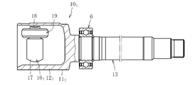
- Sliding type constant velocity universal joint 10 2 shown in FIG. 21 is a tripod type constant velocity universal joint (TJ), and a long stem portion 13 extending axially from the bottom of the cup portion 12 2 and the cup portion 12 2 an outer joint member 11 2 having an outer joint member 11 2 of the cup portion 12 the inner joint member 16 2 accommodated in the inner circumference of the 2, disposed between the outer joint member 11 2 and the inner joint member 16 2 And a roller 19 as a torque transmission element.
- the inner joint member 16 2 is composed of a tripod member 17 three trunnions 18 which the roller 19 externally fitted is provided at equal circumferential intervals.
- the inner ring of the support bearing 6 is fixed to the outer peripheral surface of the long stem portion 13, and the outer ring of the support bearing 6 is fixed to the transmission case via a bracket (not shown). ing.
- the outer joint member 11 2 is rotatably supported by the support bearing 6, deflection of the outer joint member 11 2 at the operating time or the like is prevented as much as possible.
- Figure 22 shows a partial longitudinal section of the outer joint member 11 2.
- the outer joint member 11 2 has one end open, the inner roller 19 in the circumferential direction trisected position in the circumferential surface (see FIG. 21) track grooves 30 2 rolls the inner circumferential surface 31 2 spline Sp of but a bottomed cylindrical cup portion 12 2 formed, extending axially from the bottom of the cup portion 12 2, as the torque transmitting connection portion to the outer circumference of the end portion of the opposite side of the cup portion 12 2 side And a long stem portion 13 provided with.
- the outer joint member 11 2, the cup member 12 2 a and the shaft member 13a is formed by welding.
- the cup member 12 2 a is the inner circumference to the track groove 30 2 and the inner circumferential surface 312 is formed a cylindrical portion 12 2 a1 and the bottom 12 2 integrally molded article comprising a2.
- a convex portion 12 2 a3 is formed on the bottom portion 12 2 a2 of the cup member 12 2 a.
- a boot mounting groove 32 is formed on the outer periphery of the cup member 12 2 a on the opening side.
- the shaft member 13a is a bearing mounting surface 14 and retaining ring groove 15 is formed on the outer periphery of the cup member 12 2 a side, spline Sp is formed at the opposite end from the cup member 12 2 a side.
- the welded portion 49 is formed of a bead irradiated from the radially outer side of the cup member 12 2 a. Similar to the outer joint member of the first embodiment, the outer diameter B of the joint end face 50 2 and connecting end face 51 is set to the same size for each joint size.
- Weld 49 because it is formed in the bearing mounting surface 14 cup member 12 2 a side of the joint end face 51 than the shaft member 13a, etc. bearing mount surface 14 can be eliminated post-processing after the pre-processable welding. Further, since burrs do not appear in the weld due to electron beam welding, post-processing of the weld can be omitted, and the manufacturing cost can be reduced.
- the outer joint member of the present embodiment is the same as that described above in the first embodiment of the outer joint member and the first to third embodiments of the manufacturing method described above. Duplicate explanation is omitted.
- the example in which the protruding surface is provided on the inner diameter side of the joining end surface of the cup member is illustrated, but on the contrary, the projecting surface is provided on the inner diameter side of the joining end surface of the shaft member. May be.
- the ultrasonic inspection may be performed from the surface side of the cup member.
- the electron beam welding is applied, but the same can be applied to laser welding.
- the present invention is applied to a double offset type constant velocity universal joint and a tripod type constant velocity universal joint as the sliding type constant velocity universal joint 10 has been described.
- the present invention can also be applied to an outer joint member of another sliding type constant velocity universal joint such as a cross groove type constant velocity universal joint, and further to an outer joint member of a fixed type constant velocity universal joint.
- the present invention is applied to the outer joint member of the constant velocity universal joint constituting the drive shaft.
- the present invention is also applied to the outer joint member of the constant velocity universal joint constituting the propeller shaft. Can do.
Landscapes
- Engineering & Computer Science (AREA)
- General Engineering & Computer Science (AREA)
- Mechanical Engineering (AREA)
- Physics & Mathematics (AREA)
- General Physics & Mathematics (AREA)
- Chemical & Material Sciences (AREA)
- Analytical Chemistry (AREA)
- Biochemistry (AREA)
- General Health & Medical Sciences (AREA)
- Health & Medical Sciences (AREA)
- Immunology (AREA)
- Pathology (AREA)
- Life Sciences & Earth Sciences (AREA)
- Optics & Photonics (AREA)
- Acoustics & Sound (AREA)
- Quality & Reliability (AREA)
- Plasma & Fusion (AREA)
- Welding Or Cutting Using Electron Beams (AREA)
- Pressure Welding/Diffusion-Bonding (AREA)
- Forging (AREA)
- Laser Beam Processing (AREA)
Abstract
Provided is a method for manufacturing an outer joint member for a constant-velocity universal joint, formed by welding a cup member with which a torque transmission element is engaged and a shaft member, wherein: the cup member and the shaft member are formed from medium-carbon steel; the cup member is prepared by forming a cylindrical section and a base section as a single unit by forge processing and forming a joining end surface on the outer surface of the base section in a mechanical processing step; the shaft member is prepared by forming a joining end surface that is joined to the base section of the cup member in the mechanical processing step; and the joining end surface of the cup member and the joining end surface of the shaft member are abutted and welded by irradiating the abutted sections with a beam from outside the cup member in the radial direction. In the method, the external diameter of the joining end surface of the cup member is set to the same dimension for each joint size; on the internal diameter side of the joining end surface of either the cup member or the shaft member, a projecting surface that projects further radially inward than the internal diameter of the other joining end surface is provided; and an ultrasonic flaw-detecting examination step is provided in which, after welding is performed in the foregoing state, a flaw detection is performed from the surface side of the member with the other joining end surface.
Description
この発明は、等速自在継手の外側継手部材の製造方法および外側継手部材に関する。
The present invention relates to a method for manufacturing an outer joint member of a constant velocity universal joint and an outer joint member.
自動車や各種産業機械の動力伝達系を構成する等速自在継手は、駆動側と従動側の二軸をトルク伝達可能に連結すると共に、前記二軸が作動角をとっても等速で回転トルクを伝達することができる。等速自在継手は、角度変位のみを許容する固定式等速自在継手と、角度変位および軸方向変位の両方を許容する摺動式等速自在継手とに大別され、例えば、自動車のエンジンから駆動車輪に動力を伝達するドライブシャフトにおいては、デフ側(インボード側)に摺動式等速自在継手が使用され、駆動車輪側(アウトボード側)には固定式等速自在継手が使用される。
The constant velocity universal joint that constitutes the power transmission system of automobiles and various industrial machines connects the two shafts on the drive side and the driven side so that torque can be transmitted, and transmits rotational torque at a constant speed even if the two shafts have an operating angle. can do. Constant velocity universal joints are broadly classified into fixed constant velocity universal joints that allow only angular displacement and sliding constant velocity universal joints that allow both angular displacement and axial displacement. In the drive shaft that transmits power to the drive wheel, a sliding type constant velocity universal joint is used on the differential side (inboard side), and a fixed type constant velocity universal joint is used on the drive wheel side (outboard side). The
摺動式又は固定式を問わず、等速自在継手は主要な構成部材として、内周面にトルク伝達要素が係合するトラック溝を形成したカップ部と、このカップ部の底部から軸方向に延びた軸部とを有する外側継手部材を備えている。この外側継手部材は、中実の棒状素材(バー材)を鍛造加工やしごき加工等の塑性加工、切削加工、熱処理、研削加工等を施すことによって、カップ部と軸部とを一体成形する場合が多い。
Regardless of sliding type or fixed type, the constant velocity universal joint is composed of a cup part in which a track groove that engages a torque transmitting element is formed on the inner peripheral surface, and an axial direction from the bottom part of this cup part. And an outer joint member having an extended shaft portion. This outer joint member is used to integrally form the cup and shaft by subjecting a solid bar-shaped material (bar material) to plastic processing such as forging and ironing, cutting, heat treatment, grinding, etc. There are many.
ところで、外側継手部材として、長寸の軸部(ロングステム)を有するものを用いる場合がある。左右のドライブシャフトの長さを等しくするために、片側のドライブシャフトのインボード側外側継手部材をロングステムにし、このロングステムが転がり軸受によって回転支持される。ロングステム部の長さは、車種により異なるが、概ね300~400mm程度である。この外側継手部材では、軸部が長寸であるために、カップ部と軸部を精度良く一体成形することが困難である。そのため、カップ部と軸部を別部材で構成し、両部材を摩擦圧接にて接合するものがある。このような摩擦圧接技術が、例えば、特許文献1に記載されている。
Incidentally, as the outer joint member, a member having a long shaft portion (long stem) may be used. In order to make the lengths of the left and right drive shafts equal, the inboard side outer joint member of the drive shaft on one side is made a long stem, and this long stem is rotatably supported by a rolling bearing. The length of the long stem portion varies depending on the vehicle type, but is approximately 300 to 400 mm. In this outer joint member, since the shaft portion is long, it is difficult to integrally form the cup portion and the shaft portion with high accuracy. For this reason, there is a type in which the cup portion and the shaft portion are formed of separate members and both members are joined by friction welding. Such a friction welding technique is described in Patent Document 1, for example.
特許文献1に記載された外側継手部材の摩擦圧接技術の概要を図23および図24に基づいて説明する。外側継手部材71の中間製品71’は、カップ部材72および軸部材73からなり、摩擦圧接によって接合されている。図23に示すように、接合部74は、圧接に伴って少なくとも内外径のいずれかにバリ75が生じる。外側継手部材71の中間製品71’の軸部に転がり軸受(図1参照)を装着するために、図24に示すように、接合部74の外径側のバリ75を旋削等の加工により取り除く必要がある。図示は省略するが、中間製品71’はスプラインや止め輪溝等を機械加工し、熱処理、研削加工等を経て外側継手部材71の完成品となる。したがって、外側継手部材71と中間製品71’との間に細部の形状に異なるところがあるが、図24では、説明を簡略化するため細部の形状の相違点は省略して、完成品としての外側継手部材71と中間製品71’を同じ部分に符号を付している。以降の説明においても同様とする。
The outline of the friction welding technique for the outer joint member described in Patent Document 1 will be described with reference to FIGS. The intermediate product 71 ′ of the outer joint member 71 includes a cup member 72 and a shaft member 73 and is joined by friction welding. As shown in FIG. 23, at the joining portion 74, a burr 75 is generated on at least one of the inner and outer diameters in accordance with the pressure contact. In order to mount the rolling bearing (see FIG. 1) on the shaft portion of the intermediate product 71 ′ of the outer joint member 71, the burr 75 on the outer diameter side of the joint portion 74 is removed by processing such as turning as shown in FIG. There is a need. Although illustration is omitted, the intermediate product 71 ′ is a finished product of the outer joint member 71 by machining a spline, a retaining ring groove, and the like, through heat treatment, grinding, and the like. Therefore, although there is a difference in the shape of the details between the outer joint member 71 and the intermediate product 71 ′, in FIG. 24, the difference in the shape of the details is omitted for the sake of simplicity of description, and the outer side as a finished product is omitted. The joint member 71 and the intermediate product 71 ′ are denoted by the same reference numerals. The same applies to the following description.
前述した摩擦圧接によって生じた接合部74のバリ75は、摩擦熱とその後の冷却によって焼入れされて高い硬度を有すると共に、径方向と軸方向とに広がる歪んだ形状をしている。したがって、図24に示すように、外径側のバリ75を旋削加工で除去する際、高い硬度によって旋削チップが激しく摩耗し、また、歪んだ形状によって旋削チップに欠けが生じやすい。そのため、旋削速度を上げることが難しく、旋削チップの1つのパス当たりの切削量が少なくパス数が増大するので、サイクルタイムが長く製造コストが上がるという問題がある。
The burrs 75 of the joint 74 generated by the friction welding described above are hardened by friction heat and subsequent cooling, and have a distorted shape spreading in the radial direction and the axial direction. Therefore, as shown in FIG. 24, when the burr 75 on the outer diameter side is removed by turning, the turning tip is abraded violently due to high hardness, and the turning tip tends to be chipped due to the distorted shape. For this reason, it is difficult to increase the turning speed, and the amount of cutting per pass of the turning tip is small and the number of passes is increased. Therefore, there is a problem that the cycle time is long and the manufacturing cost is increased.
また、外側継手部材71の接合部74の接合状態を検査するために、高速探傷が可能な超音波探傷を行おうとしても、接合部74の内径側に残るバリ75によって超音波が散乱するため接合状態を確認できない。したがって、接合後、超音波探傷による全数検査ができないという問題もある。
Further, in order to inspect the joining state of the joint portion 74 of the outer joint member 71, even if an ultrasonic flaw capable of high-speed flaw detection is performed, the ultrasonic waves are scattered by the burr 75 remaining on the inner diameter side of the joint portion 74. The joining state cannot be confirmed. Therefore, after joining, there is also a problem that 100% inspection cannot be performed by ultrasonic flaw detection.
上記の問題に対して、接合にレーザ溶接あるいは電子ビーム溶接を行うことによって、摩擦圧接のような接合部表面の盛り上がりを抑えることが考えられるが、図25に示すようなカップ部材72と軸部材73を突き合わせて溶接した場合、溶接中の加工熱により、中空空洞部76内の気体圧力が上昇し、溶接終了後は圧力の減少が生じる。この中空空洞部76の内圧の変化により、溶融物の吹き上がりが発生し、溶接部の外径の表面に凹み、溶接深さ不良や溶接内部に気泡が生じて溶接状態が悪化する。その結果、溶接部の強度が安定せず、品質に悪影響を及ぼすことになる。
In order to solve the above problem, it is conceivable to suppress the rise of the surface of the joint portion such as friction welding by performing laser welding or electron beam welding for joining, but the cup member 72 and the shaft member as shown in FIG. When the welding is performed while abutting 73, the gas pressure in the hollow cavity 76 increases due to the processing heat during welding, and the pressure decreases after the end of welding. Due to the change in the internal pressure of the hollow cavity portion 76, the melt is blown up, the surface of the welded portion is recessed, the weld depth is poor, and bubbles are generated inside the weld to deteriorate the welded state. As a result, the strength of the welded portion is not stable, and the quality is adversely affected.
さらに、前述した図23および図24の摩擦圧接や図25の溶接に用いたカップ部材72と軸部材73は、車種毎に異なる形状、寸法の軸部分の途中位置で接合するものである。そのため、後述するように生産性の向上やカップ部材の品種統合によるコスト低減の面でも問題があることが判明した。
Furthermore, the cup member 72 and the shaft member 73 used for the friction welding shown in FIGS. 23 and 24 and the welding shown in FIG. 25 are joined at intermediate positions of shaft portions having different shapes and dimensions for each vehicle type. Therefore, as described later, it has been found that there is a problem in terms of cost reduction by improving productivity and integrating cup member types.
加えて、レーザ溶接や電子ビーム溶接では溶接ビードの盛り上がりを抑えられるので、超音波探傷による全数検査が可能であるが、自動車用等の量産製品である等速自在継手の外側継手部材であるため、溶接部の検査精度および検査作業性の向上を図ることが不可欠であることに着目した。
In addition, the rise of the weld bead can be suppressed in laser welding and electron beam welding, so 100% inspection by ultrasonic flaw detection is possible, but it is an outer joint member of a constant velocity universal joint that is a mass-produced product for automobiles etc. We focused on improving the inspection accuracy and inspection workability of welds.
本発明は、前述の問題点に鑑みて提案されたもので、その目的とするところは、溶接部の強度、品質の向上と共に検査精度、検査作業性の向上、溶接コストの削減、生産性の向上、並びに品種統合によるコスト低減、生産管理の負荷低減を可能にする外側継手部材の製造方法および外側継手部材を提供することにある。
The present invention has been proposed in view of the above-mentioned problems, and its purpose is to improve the strength and quality of the welded portion, as well as improve inspection accuracy, inspection workability, reduce welding costs, and improve productivity. An object of the present invention is to provide an outer joint member manufacturing method and an outer joint member that can be improved, reduce costs by integrating products, and reduce the load of production management.
本発明者らは、上記の目的を達成するため鋭意検討および検証し、以下の知見を見出した。そして、これらの多面的な知見を基に、量産性を考慮した新たな製造コンセプトを着想し、本発明に至った。
(1)生産技術の面では、カップ部材と軸部材を密閉空間に設置して真空引きし、中空空洞部も真空化された状態で溶接することで溶融物の吹き上がりや気泡の発生が抑えられる。
(2)また、生産性の面では、生産性向上を図るために焼入れ焼戻しの熱処理を施したカップ部材と軸部材を溶接する場合、溶接時の熱で周辺部の温度が上昇し、熱処理部の硬度が低下する懸念がある。この問題に対しては、溶接工程の順序の入れ替えにより、継手機能への影響がない範囲で最も効率的でコスト低減が可能な工程で接合するという方法に着目した。例えば、溶接時の熱影響がないものであれば、焼入れ焼戻しの熱処理を施した完成状態のカップ部材と軸部材を溶接し、一方、熱影響があるものは、溶接後の熱処理とする工程とするなど、カップ部材や軸部材の形状、仕様等に応じて最適な工程をとるコンセプトを見出した。
(3)さらに、生産性や品種統合の面では、図23~25に示すカップ部材72には、次のような問題があることが判明した。すなわち、カップ部材72は、鍛造加工等によりカップ部の底部より縮径された短軸部が形成されるが、この短軸部が軸部材73の形状、寸法を基準にして設定され、軸部の途中位置で接合される構成となっている。軸部材73は、組み付けられる車両によって、標準的な長さのステムやロングステムというタイプの違いに加えて、種々の軸径や外周形状が要求される。このため、カップ部材72の短軸部を軸部材73の形状、寸法を基準にして設定し、軸部の途中位置で接合する場合、軸部材73と接合されるカップ部材72の短軸部の軸径(接合径)や形状、長さ(接合位置)の両方が異なるため、一種類の軸部材73に対して専用のカップ部材72が必要になる。したがって、生産性の向上やカップ部材の品種統合によるコスト低減の面でも問題があることが判明した。
(4)加えて、自動車用等の量産製品である等速自在継手の外側継手部材の新たな製造コンセプトを実用面で成立させるためには、溶接部の検査精度および検査作業性の向上を可能にする超音波探傷検査の方法や溶接部形状に工夫が必要であることが判明した。 The present inventors diligently studied and verified to achieve the above object, and found the following findings. And based on these multifaceted findings, a new manufacturing concept that takes mass productivity into consideration was conceived and the present invention was achieved.
(1) In terms of production technology, the cup member and shaft member are placed in a sealed space and evacuated, and the hollow cavity is also welded in a vacuumed state, thereby preventing the melt from blowing up and generating bubbles. It is done.
(2) Further, in terms of productivity, when welding a cup member and a shaft member that have been subjected to quenching and tempering heat treatment in order to improve productivity, the temperature of the peripheral portion increases due to heat during welding, and the heat treatment portion There is a concern that the hardness of the steel will decrease. For this problem, we focused on the method of joining in the most efficient and cost-effective process within the range that does not affect the joint function by changing the order of the welding process. For example, if there is no thermal influence during welding, the cup member and the shaft member in a finished state subjected to heat treatment of quenching and tempering are welded, while those having thermal influence are steps of heat treatment after welding and The concept which took the most suitable process according to the shape, specification, etc. of the cup member and the shaft member was found.
(3) Further, in terms of productivity and product integration, it has been found that thecup member 72 shown in FIGS. 23 to 25 has the following problems. In other words, the cup member 72 is formed with a short shaft portion whose diameter is reduced from the bottom portion of the cup portion by forging or the like. The short shaft portion is set based on the shape and dimensions of the shaft member 73, and the shaft portion It is the structure joined in the middle position. The shaft member 73 is required to have various shaft diameters and outer peripheral shapes in addition to the standard length stem and long stem type depending on the vehicle to be assembled. For this reason, when the short shaft portion of the cup member 72 is set with reference to the shape and dimensions of the shaft member 73 and joined at an intermediate position of the shaft portion 73, the short shaft portion of the cup member 72 joined to the shaft member 73 Since both the shaft diameter (joining diameter), shape, and length (joining position) are different, a dedicated cup member 72 is required for one kind of shaft member 73. Therefore, it has been found that there is a problem in terms of cost reduction by improving productivity and integrating cup member types.
(4) In addition, in order to establish a new manufacturing concept for the outer joint member of constant velocity universal joints, which are mass-produced products for automobiles, etc., it is possible to improve the inspection accuracy and inspection workability of welds. It has been found that it is necessary to devise the ultrasonic flaw detection method and the shape of the weld.
(1)生産技術の面では、カップ部材と軸部材を密閉空間に設置して真空引きし、中空空洞部も真空化された状態で溶接することで溶融物の吹き上がりや気泡の発生が抑えられる。
(2)また、生産性の面では、生産性向上を図るために焼入れ焼戻しの熱処理を施したカップ部材と軸部材を溶接する場合、溶接時の熱で周辺部の温度が上昇し、熱処理部の硬度が低下する懸念がある。この問題に対しては、溶接工程の順序の入れ替えにより、継手機能への影響がない範囲で最も効率的でコスト低減が可能な工程で接合するという方法に着目した。例えば、溶接時の熱影響がないものであれば、焼入れ焼戻しの熱処理を施した完成状態のカップ部材と軸部材を溶接し、一方、熱影響があるものは、溶接後の熱処理とする工程とするなど、カップ部材や軸部材の形状、仕様等に応じて最適な工程をとるコンセプトを見出した。
(3)さらに、生産性や品種統合の面では、図23~25に示すカップ部材72には、次のような問題があることが判明した。すなわち、カップ部材72は、鍛造加工等によりカップ部の底部より縮径された短軸部が形成されるが、この短軸部が軸部材73の形状、寸法を基準にして設定され、軸部の途中位置で接合される構成となっている。軸部材73は、組み付けられる車両によって、標準的な長さのステムやロングステムというタイプの違いに加えて、種々の軸径や外周形状が要求される。このため、カップ部材72の短軸部を軸部材73の形状、寸法を基準にして設定し、軸部の途中位置で接合する場合、軸部材73と接合されるカップ部材72の短軸部の軸径(接合径)や形状、長さ(接合位置)の両方が異なるため、一種類の軸部材73に対して専用のカップ部材72が必要になる。したがって、生産性の向上やカップ部材の品種統合によるコスト低減の面でも問題があることが判明した。
(4)加えて、自動車用等の量産製品である等速自在継手の外側継手部材の新たな製造コンセプトを実用面で成立させるためには、溶接部の検査精度および検査作業性の向上を可能にする超音波探傷検査の方法や溶接部形状に工夫が必要であることが判明した。 The present inventors diligently studied and verified to achieve the above object, and found the following findings. And based on these multifaceted findings, a new manufacturing concept that takes mass productivity into consideration was conceived and the present invention was achieved.
(1) In terms of production technology, the cup member and shaft member are placed in a sealed space and evacuated, and the hollow cavity is also welded in a vacuumed state, thereby preventing the melt from blowing up and generating bubbles. It is done.
(2) Further, in terms of productivity, when welding a cup member and a shaft member that have been subjected to quenching and tempering heat treatment in order to improve productivity, the temperature of the peripheral portion increases due to heat during welding, and the heat treatment portion There is a concern that the hardness of the steel will decrease. For this problem, we focused on the method of joining in the most efficient and cost-effective process within the range that does not affect the joint function by changing the order of the welding process. For example, if there is no thermal influence during welding, the cup member and the shaft member in a finished state subjected to heat treatment of quenching and tempering are welded, while those having thermal influence are steps of heat treatment after welding and The concept which took the most suitable process according to the shape, specification, etc. of the cup member and the shaft member was found.
(3) Further, in terms of productivity and product integration, it has been found that the
(4) In addition, in order to establish a new manufacturing concept for the outer joint member of constant velocity universal joints, which are mass-produced products for automobiles, etc., it is possible to improve the inspection accuracy and inspection workability of welds. It has been found that it is necessary to devise the ultrasonic flaw detection method and the shape of the weld.
前述の目的を達成するための技術的手段として、本発明は、トルク伝達要素が係合するトラック溝を内周に形成したカップ部と、このカップ部の底部に形成された軸部とを別部材で構成し、前記カップ部を形成するカップ部材と前記軸部を形成する軸部材とを溶接してなる等速自在継手の外側継手部材の製造方法において、前記カップ部材と軸部材を中炭素鋼で形成し、前記カップ部材として、その筒状部と底部を鍛造加工により一体に形成した後、機械加工工程において前記底部の外面に接合用端面を形成したカップ部材を準備し、前記軸部材として、機械加工工程において前記カップ部材の底部と接合される接合用端面を形成した軸部材を準備し、前記カップ部材の接合用端面と軸部材の接合用端面を突合せて、この突合せ部に前記カップ部材の外側から半径方向にビームを照射して溶接するものであって、前記カップ部材の接合用端面の外径をジョイントサイズ毎に同一寸法とし、前記カップ部材と軸部材の接合用端面のうち一方の接合用端面の内径側に他方の接合用端面の内径より半径方向内側に突出した突出面を設け、この状態で溶接を行った後、前記他方の接合用端面を有する部材の表面側から探傷を行う超音波探傷検査工程を備えていることを特徴とする。
As a technical means for achieving the above-mentioned object, the present invention separates a cup portion formed on the inner periphery with a track groove engaged with a torque transmitting element and a shaft portion formed on the bottom portion of the cup portion. In the manufacturing method of the outer joint member of the constant velocity universal joint which comprises a member and welds the cup member forming the cup portion and the shaft member forming the shaft portion, the cup member and the shaft member are made of medium carbon After forming the cylindrical part and the bottom part integrally by forging as the cup member, the cup member is prepared by forming a joining end face on the outer surface of the bottom part in the machining step, and the shaft member. As a shaft member formed with a joining end face to be joined to the bottom of the cup member in a machining step, the joining end face of the cup member and the joining end face of the shaft member are abutted, and the abutting portion is Mosquito The outer diameter of the joint member is irradiated with a beam in the radial direction, and the outer diameter of the joint end surface of the cup member is the same for each joint size, and the joint member end surface of the cup member and the shaft member is welded. A protruding surface protruding radially inward from the inner diameter of the other joining end face is provided on the inner diameter side of one joining end face, and after welding in this state, the surface side of the member having the other joining end face It comprises an ultrasonic flaw detection inspection process for flaw detection.
また、等速自在継手の外側継手部材としての本発明は、トルク伝達要素が係合するトラック溝を内周に形成したカップ部と、このカップ部の底部に形成された軸部とを別部材で構成し、前記カップ部を形成するカップ部材と前記軸部を形成する軸部材とを溶接してなる等速自在継手の外側継手部材において、前記カップ部材と軸部材が中炭素鋼からなり、前記カップ部材は、鍛造加工により筒状部と底部が一体成形され、この底部の外面に接合用端面が形成されたものであり、前記軸部材は、前記底部に接合される端部に接合用端面が形成されたものであり、前記両接合用端面を突合せて前記カップ部材と軸部材が溶接されており、この溶接部が前記カップ部材の外側から半径方向に照射されたビームによるビードで形成されていると共に、前記カップ部材の接合用端面の外径がジョイントサイズ毎に同一寸法に設定され、前記カップ部材と軸部材の接合用端面のうち一方の接合用端面の内径側に他方の接合用端面の内径より半径方向内側に突出した突出面が設けられ、この状態で溶接されていることを特徴とする。
Further, the present invention as an outer joint member of a constant velocity universal joint includes a cup part formed on the inner periphery of a track groove with which a torque transmission element engages and a shaft part formed on the bottom part of the cup part as separate members. In the outer joint member of the constant velocity universal joint formed by welding the cup member forming the cup portion and the shaft member forming the shaft portion, the cup member and the shaft member are made of medium carbon steel, In the cup member, a cylindrical portion and a bottom portion are integrally formed by forging, and a joining end surface is formed on an outer surface of the bottom portion. The shaft member is joined to an end portion to be joined to the bottom portion. An end surface is formed, the cup member and the shaft member are welded by abutting the joint end surfaces, and the welded portion is formed by a bead of a beam irradiated radially from the outside of the cup member. With being The outer diameter of the joining end face of the cup member is set to the same dimension for each joint size, and the inner diameter side of one joining end face of the joining end faces of the cup member and the shaft member is larger than the inner diameter of the other joining end face. A projecting surface projecting radially inward is provided and welded in this state.
上記の構成により、溶接部の強度、品質の向上、溶接コストの削減、溶接部の検査精度および検査作業性の向上と共に、カップ部材および軸部材の生産性の向上、並びにカップ部材の品種統合によるコスト低減、生産管理の軽減が可能な外側継手部材の製造方法および外側継手部材を実現することができる。
By the above configuration, the strength and quality of the welded part, the reduction of welding cost, the inspection accuracy of the welded part and the inspection workability are improved, the productivity of the cup member and the shaft member is improved, and the cup member is integrated. An outer joint member manufacturing method and an outer joint member capable of reducing costs and reducing production management can be realized.
具体的には、上記の超音波探傷検査工程において、溶接後のカップ部材と軸部材を水中に載置し、探傷することが好ましい。これにより、検査精度を一層向上させることができる。
Specifically, in the ultrasonic flaw detection inspection process, it is preferable to place the welded cup member and shaft member in water and perform flaw detection. Thereby, inspection accuracy can be further improved.
上記の突出面をジョイントサイズ毎に同一にすることや、突出面をカップ部材の接合用端面に設けることにより、品種統合するカップ部材の加工度を高め、生産性の向上および生産管理の軽減を一層促進することができる。また、溶接部の超音波探傷検査の際、軸径の小さい軸部材の表面側から斜角探触子により超音波を入射できるので、探傷検査が容易にできる。
By making the above protruding surface the same for each joint size and providing the protruding surface on the end surface for joining the cup member, the degree of processing of the cup member to be integrated is improved, and productivity is improved and production control is reduced. It can be further promoted. Moreover, since ultrasonic waves can be incident from the surface side of the shaft member having a small shaft diameter by the oblique probe at the time of ultrasonic flaw inspection of the welded portion, flaw detection inspection can be facilitated.
ここで、特許請求の範囲および本明細書において、カップ部材の接合用端面の外径をジョイントサイズ毎に同一寸法にしたことや、突出面をジョイントサイズ毎に同一にしたとは、カップ部材が1つのジョイントサイズで1種類、すなわち、1品番ということに限定されるものではなく、例えば、最大作動角の異なる仕様により1つのジョイントサイズで複数の種類(複数品番)のカップ部材を設定し、これらのカップ部材の上記接合用端面の外径を同一寸法にしたものや、上記突出面を同一に設定したものを包む概念のものである。また、これに加えて、例えば、継手機能や製造現場の実情、生産性等を考慮して、カップ部材を熱処理前の中間部品と熱処理を施した完成部品の複数形態で管理するために、1つのジョイントサイズで複数の種類(複数品番)のカップ部材を設定し、これらのカップ部材の上記接合用端面の外径を同一寸法にしたものや、上記突出面を同一に設定したものも包むものである。
Here, in the claims and the present specification, the outer diameter of the joining end surface of the cup member is the same for each joint size, or the protruding surface is the same for each joint size, One joint size is not limited to one type, that is, one part number. For example, multiple types (multiple part numbers) of cup members are set with one joint size according to different specifications of the maximum operating angle, These cup members have a concept of wrapping those having the same outer diameter of the joining end faces and those having the same protruding surfaces. In addition, in order to manage the cup member in a plurality of forms of intermediate parts before heat treatment and completed parts subjected to heat treatment, for example, considering the joint function, actual situation at the manufacturing site, productivity, etc., 1 A plurality of types (multiple product numbers) of cup members are set with one joint size, and the outer diameters of the end surfaces for joining of these cup members are the same size, and those with the same protruding surface are also included. .
さらに、特許請求の範囲および明細書において、カップ部材の接合用端面の外径をジョイントサイズ毎に同一寸法にしたことや、突出面をジョイントサイズ毎に同一にしたことは、等速自在継手の形式が異なる場合も含むものであり、例えば、インボード側では、トリポード型等速自在継手とダブルオフセット型等速自在継手の上記接合用端面の外径を同一寸法にすることおよび上記突出面を同一に設定することや、アウトボード側では、ツェッパ型等速自在継手とアンダーカットフリー型等速自在継手の上記接合用端面の外径を同一寸法にすることおよび上記突出面を同一に設定することも含む概念のものである。さらには、インボード側とアウトボード側の等速自在継手の上記接合用端面の外径を同一寸法にすることおよび上記突出面を同一に設定することも可能である。
Furthermore, in the claims and the specification, the fact that the outer diameter of the joining end face of the cup member is the same for each joint size, and the protruding face is the same for each joint size, For example, on the inboard side, the outer diameter of the end surface for joining of the tripod type constant velocity universal joint and the double offset type constant velocity universal joint is made the same dimension and the protruding surface is On the outboard side, the outer diameter of the end face for joining of the Rzeppa type constant velocity universal joint and the undercut free type constant velocity universal joint is set to the same size, and the protruding surface is set to be the same. It is a concept that includes things. Furthermore, it is possible to make the outer diameters of the joint end faces of the constant velocity universal joints on the inboard side and the outboard side the same, and to set the protruding surfaces to be the same.
上記の溶接前のカップ部材と軸部材の少なくとも一方を、熱処理を施さない中間部品とすることができる。この場合は、溶接後、熱処理と研削加工や焼入鋼切削等の仕上げ加工を施す。溶接時の熱で周辺部の温度が上昇し、熱処理部の硬度に影響がある形状や仕様のカップ部材および軸部材に適する。上記の中間部品に品番を付与して管理する。
少 な く と も At least one of the cup member and the shaft member before welding can be an intermediate part that is not subjected to heat treatment. In this case, after welding, finish processing such as heat treatment, grinding, and hardened steel cutting is performed. It is suitable for cup members and shaft members having shapes and specifications that affect the hardness of the heat-treated portion because the temperature at the periphery increases due to the heat during welding. Part numbers are assigned to the above intermediate parts for management.
また、上記の溶接前のカップ部材と軸部材の少なくとも一方を、熱処理を施した完成部品とすることができる。熱処理および熱処理後の研削加工や焼入鋼切削等の仕上げ加工が施された完成部品とすることにより、ジョイントサイズ毎に共用化された完成部品としてのカップ部材と車種毎に種々の軸部仕様を備えた軸部材が得られるので、それぞれ、品番を付与して管理することができる。したがって、カップ部材の品種統合によるコスト低減、生産管理の負荷軽減が顕著になる。また、共用化されたカップ部材と種々の軸部仕様を備えた軸部材は、鍛造加工、旋削加工、熱処理、さらには研削加工や焼入鋼切削等の仕上げ加工を経た完成部品まで、それぞれ別々に製造でき、段取り削減等も含めて生産性が向上する。ただし、完成部品としてのカップ部材や軸部材とは、前述した熱処理後の研削加工や焼入鋼切削等の仕上げ加工が施されたものに限られず、この仕上げ加工を残した熱処理完了状態のカップ部材や軸部材を含む概念のものである。
Also, at least one of the cup member and the shaft member before welding can be a finished part subjected to heat treatment. Finished parts such as heat treatment and post-heat treatment grinding and hardened steel cutting, etc., so that the finished cup parts can be shared for each joint size and various shaft specifications for each vehicle type Since the shaft member provided with is obtained, the product number can be assigned and managed. Therefore, the cost reduction and the production management load reduction due to the integration of the cup member types become remarkable. In addition, the common cup member and the shaft member with various shaft specifications can be used separately for finished parts such as forging, turning, heat treatment, and finishing such as grinding and hardened steel cutting. The productivity is improved, including the reduction of setup. However, the cup member and shaft member as a finished part are not limited to those subjected to the finishing processing such as grinding and quenching steel cutting after the heat treatment described above. The concept includes a member and a shaft member.
上記の溶接を電子ビーム溶接とすることにより、接合部にバリが生じることがない。接合部の後加工の省略による製造コスト削減、さらには、接合部の超音波探傷による全数検査がより確実に実施できる。また、電子ビーム溶接により、深い溶け込みが得られるので溶接強度が高く、かつ熱歪を小さくできる。
¡By using the above welding as electron beam welding, burrs do not occur at the joint. The manufacturing cost can be reduced by omitting the post-processing of the joint portion, and moreover, 100% inspection by ultrasonic flaw detection of the joint portion can be more reliably performed. Further, since deep penetration is obtained by electron beam welding, the welding strength is high and the thermal strain can be reduced.
上記のカップ部材と軸部材を密閉空間に設置して大気圧以下の状態で溶接することが望ましい。これにより、溶融物の吹き上がりや気泡の発生が抑えられ、溶接部の強度や品質が向上する。
It is desirable to place the above cup member and shaft member in a sealed space and weld in a state below atmospheric pressure. Thereby, the blow-up of the melt and the generation of bubbles are suppressed, and the strength and quality of the welded portion are improved.
上記のカップ部材と軸部材の溶接部の硬度はHv200~500の範囲が好ましい。Hv200未満では製品機能上必要な強度の確保が困難であり望ましくない。一方、Hv500を超えると相変態に伴う割れおよび靱性の変化による疲労強度の低下などが発生する恐れが生じるため望ましくない。
The hardness of the welded portion between the cup member and the shaft member is preferably in the range of Hv 200 to 500. If it is less than Hv200, it is difficult to ensure the strength required for the product function, which is not desirable. On the other hand, if it exceeds Hv500, it is not desirable because cracks associated with phase transformation and a decrease in fatigue strength due to changes in toughness may occur.
本発明に係る等速自在継手の外側継手部材の製造方法および外側継手部材によれば、溶接部の強度、品質の向上、溶接コストの削減、溶接部の検査精度および検査作業性の向上と共に、カップ部材および軸部材の生産性の向上、並びにカップ部材の品種統合によるコスト低減、生産管理の軽減が可能な外側継手部材の製造方法および外側継手部材を実現することができる。
According to the outer joint member manufacturing method and the outer joint member of the constant velocity universal joint according to the present invention, the strength of the welded portion, the improvement of quality, the reduction of the welding cost, the inspection accuracy of the welded portion and the improvement of the inspection workability, An outer joint member manufacturing method and an outer joint member capable of improving the productivity of cup members and shaft members, reducing the cost by integrating the types of cup members, and reducing production management can be realized.
以下に本発明の実施の形態を図面に基づいて説明する。
Embodiments of the present invention will be described below with reference to the drawings.
本発明に係る等速自在継手の外側継手部材の製造方法についての第1の実施形態を図3~16に示し、本発明に係る外側継手部材についての第1の実施形態を図1および図2に示す。はじめに、外側継手部材についての第1の実施形態を図1および図2に基づいて説明し、続いて、外側継手部材の製造方法についての第1の実施形態を図3~16に基づいて説明する。
3 to 16 show a first embodiment of a method for manufacturing an outer joint member of a constant velocity universal joint according to the present invention, and FIGS. 1 and 2 show a first embodiment of the outer joint member according to the present invention. Shown in First, a first embodiment of an outer joint member will be described with reference to FIGS. 1 and 2, and then a first embodiment of a method for manufacturing an outer joint member will be described with reference to FIGS. .
図1は、第1の実施形態の外側継手部材11が使用されたドライブシャフト1の全体構造を示す図である。ドライブシャフト1は、デフ側(図中右側:以下、インボード側ともいう)に配置される摺動式等速自在継手10と、駆動車輪側(図中左側:以下、アウトボード側ともいう)に配置される固定式等速自在継手20と、両等速自在継手10、20をトルク伝達可能に連結する中間シャフト2とを主要な構成とする。
FIG. 1 is a diagram showing an overall structure of a drive shaft 1 in which the outer joint member 11 of the first embodiment is used. The drive shaft 1 includes a sliding type constant velocity universal joint 10 disposed on the differential side (right side in the figure: hereinafter also referred to as inboard side) and a drive wheel side (left side in the figure: hereinafter also referred to as outboard side). The fixed type constant velocity universal joint 20 and the intermediate shaft 2 that couples the two constant velocity universal joints 10 and 20 so as to transmit torque are the main components.
図1に示す摺動式等速自在継手10は、いわゆるダブルオフセット型等速自在継手(DOJ)である。この等速自在継手10は、カップ部12とカップ部12の底部から軸方向に延びた長寸軸部(以下、ロングステム部ともいう)13とを有する外側継手部材11と、外側継手部材11のカップ部12の内周に収容された内側継手部材16と、外側継手部材11と内側継手部材16のトラック溝30、40との間に配置されたトルク伝達要素としてのボール41と、外側継手部材11の筒状内周面42と内側継手部材16の球状外周面43とに、それぞれ嵌合する球状外周面45、球状内周面46を有し、ボール41を保持する保持器44とを備える。保持器44の球状外周面45の曲率中心O1と球状内周面46の曲率中心O2は、継手中心Oに対して、軸方向に反対側に等距離オフセットされている。
A sliding type constant velocity universal joint 10 shown in FIG. 1 is a so-called double offset type constant velocity universal joint (DOJ). The constant velocity universal joint 10 includes an outer joint member 11 having a cup portion 12 and a long shaft portion (hereinafter, also referred to as a long stem portion) 13 extending in the axial direction from the bottom portion of the cup portion 12, and an outer joint member 11. An inner joint member 16 accommodated in the inner periphery of the cup portion 12, a ball 41 as a torque transmission element disposed between the outer joint member 11 and the track grooves 30, 40 of the inner joint member 16, and an outer joint. A cylindrical inner peripheral surface 42 of the member 11 and a spherical outer peripheral surface 43 of the inner joint member 16 are fitted with a spherical outer peripheral surface 45 and a spherical inner peripheral surface 46, respectively, and a cage 44 holding the ball 41. Prepare. The center of curvature O 1 of the spherical outer peripheral surface 45 of the cage 44 and the center of curvature O 2 of the spherical inner peripheral surface 46 are offset from the joint center O by the same distance on the opposite side in the axial direction.
ロングステム部13の外周面にはサポートベアリング6の内輪が固定されており、このサポートベアリング6の外輪は、図示しないブラケットを介してトランスミッションケースに固定されている。外側継手部材11は、サポートベアリング6によって回転自在に支持され、このようなサポートベアリング6を設けておくことにより、運転時等における外側継手部材11の振れが可及的に防止される。
The inner ring of the support bearing 6 is fixed to the outer peripheral surface of the long stem portion 13, and the outer ring of the support bearing 6 is fixed to the transmission case via a bracket (not shown). The outer joint member 11 is rotatably supported by the support bearing 6, and by providing such a support bearing 6, the outer joint member 11 is prevented from swinging during operation or the like as much as possible.
図1に示す固定式等速自在継手20は、いわゆるツェッパ型等速自在継手であり、有底筒状のカップ部21aとカップ部21aの底部から軸方向に延びた軸部21bとを有する外側継手部材21と、外側継手部材21のカップ部21aの内周に収容された内側継手部材22と、外側継手部材21のカップ部21aと内側継手部材22との間に配置されたトルク伝達要素としてのボール23と、外側継手部材21のカップ部21aの内周面と内側継手部材22の外周面との間に配され、ボール23を保持する保持器24とを備える。なお、固定式等速自在継手20として、アンダーカットフリー型等速自在継手が用いられる場合もある。
A fixed type constant velocity universal joint 20 shown in FIG. 1 is a so-called Rzeppa type constant velocity universal joint, and has an outer side having a bottomed cylindrical cup portion 21a and a shaft portion 21b extending in the axial direction from the bottom portion of the cup portion 21a. As a torque transmission element disposed between the joint member 21, the inner joint member 22 accommodated in the inner periphery of the cup portion 21 a of the outer joint member 21, and the cup portion 21 a and the inner joint member 22 of the outer joint member 21. And a cage 24 that is disposed between the inner peripheral surface of the cup portion 21 a of the outer joint member 21 and the outer peripheral surface of the inner joint member 22 and holds the ball 23. An undercut-free type constant velocity universal joint may be used as the fixed type constant velocity universal joint 20.
中間シャフト2は、その両端部外径にトルク伝達用のスプライン(セレーションを含む。以下、同じ)3を有する。そして、インボード側のスプライン3を摺動式等速自在継手10の内側継手部材16の孔部とスプライン嵌合させることにより、中間シャフト2と摺動式等速自在継手10の内側継手部材16とがトルク伝達可能に連結される。また、アウトボード側のスプライン3を固定式等速自在継手20の内側継手部材22の孔部とスプライン嵌合させることにより、中間シャフト2と固定式等速自在継手20の内側継手部材22とがトルク伝達可能に連結される。この中間シャフト2として、中実タイプを示したが、中空タイプを用いることもできる。
The intermediate shaft 2 has torque transmission splines (including serrations; the same applies hereinafter) 3 at the outer diameters at both ends. Then, the spline 3 on the inboard side is spline-fitted with the hole portion of the inner joint member 16 of the sliding type constant velocity universal joint 10, whereby the inner joint member 16 of the intermediate shaft 2 and the sliding type constant velocity universal joint 10. Are coupled so that torque can be transmitted. Further, the spline 3 on the outboard side is spline-fitted with the hole of the inner joint member 22 of the fixed type constant velocity universal joint 20, so that the intermediate shaft 2 and the inner joint member 22 of the fixed type constant velocity universal joint 20 are connected. Connected to transmit torque. As the intermediate shaft 2, a solid type is shown, but a hollow type can also be used.
両等速自在継手10、20の内部には潤滑剤としてのグリースが封入されている。グリースの外部漏洩や継手外部からの異物侵入を防止するため、摺動式等速自在継手10の外側継手部材11と中間シャフト2との間、および固定式等速自在継手20の外側継手部材21と中間シャフト2との間には、蛇腹状のブーツ4、5がそれぞれ装着されている。
In the constant velocity universal joints 10 and 20, grease as a lubricant is sealed. In order to prevent external leakage of grease and entry of foreign matter from the outside of the joint, the outer joint member 21 between the outer joint member 11 of the sliding type constant velocity universal joint 10 and the intermediate shaft 2 and the fixed type constant velocity universal joint 20 is used. Between the two and the intermediate shaft 2, bellows- like boots 4 and 5 are mounted, respectively.
図2に基づき、第1の実施形態の外側継手部材を説明する。図2は、本実施形態の外側継手部材11を拡大して示したもので、図2aは部分縦断面図で、図2bは、図2aのA部の拡大図で、図2cは溶接前の形状を示す図である。外側継手部材11は、一端が開口し、内周面の円周方向等間隔にボール41(図1参照)が転動する複数のトラック溝30と筒状内周面42が形成された有底筒状のカップ部12と、カップ部12の底部から軸方向に延び、カップ部12とは反対側の端部外周にトルク伝達用連結部としてのスプラインSpが設けられたロングステム部13とからなる。本実施形態では、外側継手部材11は、カップ部材12a、軸部材13aが溶接されて形成されている。
The outer joint member of the first embodiment will be described based on FIG. 2 is an enlarged view of the outer joint member 11 of the present embodiment. FIG. 2a is a partial longitudinal sectional view, FIG. 2b is an enlarged view of a portion A in FIG. 2a, and FIG. It is a figure which shows a shape. The outer joint member 11 is open at one end, and has a bottom with a plurality of track grooves 30 and a cylindrical inner peripheral surface 42 on which balls 41 (see FIG. 1) roll at equal intervals in the circumferential direction of the inner peripheral surface. From a cylindrical cup portion 12 and a long stem portion 13 that extends in the axial direction from the bottom portion of the cup portion 12 and is provided with a spline Sp as a torque transmission connecting portion on the outer periphery of the end opposite to the cup portion 12. Become. In the present embodiment, the outer joint member 11 is formed by welding a cup member 12a and a shaft member 13a.
図2a~図2cに示すカップ部材12aは、S53C等の0.40~0.60重量%の炭素を含む中炭素鋼からなり、内周にトラック溝30と筒状内周面42が形成された筒状部12a1と底部12a2からなる一体成形品である。カップ部材12aの底部12a2には凸部12a3が形成されている。カップ部材12aの開口側の外周にはブーツ取付溝32が形成され、内周には止め輪溝33が形成されている。軸部材13aは、カップ部材12a側の外周に軸受装着面14および止め輪溝15が形成され、反対側の端部にスプラインSpが形成されている。
The cup member 12a shown in FIGS. 2a to 2c is made of medium carbon steel containing 0.40 to 0.60% by weight of carbon such as S53C, and has a track groove 30 and a cylindrical inner peripheral surface 42 formed on the inner periphery. It is an integrally molded product comprising a cylindrical portion 12a1 and a bottom portion 12a2. A convex portion 12a3 is formed on the bottom portion 12a2 of the cup member 12a. A boot mounting groove 32 is formed on the outer periphery on the opening side of the cup member 12a, and a retaining ring groove 33 is formed on the inner periphery. The shaft member 13a has a bearing mounting surface 14 and a retaining ring groove 15 formed on the outer periphery on the cup member 12a side, and a spline Sp formed on the opposite end.
軸部材13aは、S40C等の0.30~0.55重量%の炭素を含む中炭素鋼からなる。カップ部材12aの底部12a2の凸部12a3に形成された接合用端面50と軸部材13aのカップ部材12a側端部の接合用端面51とを突合せ、カップ部材12aの外側から半径方向に電子ビーム溶接により溶接されている。図2aおよび図2bに示すように、溶接部49は、カップ部材12aの半径方向外側から照射されたビームによるビードで形成されている。詳細は後述するが、接合用端面50と接合用端面51の外径B(図4b、図5c参照)は、ジョイントサイズ毎に同一寸法に設定されている。ただし、カップ部材12aの接合用端面50の外径Bと軸部材13aの接合用端面51の外径Bを、必ずしも同一寸法にする必要はなく、例えば、溶接ビードの状態などを考慮して、接合用端面50の外径Bに対して接合用端面51の外径Bを若干小径にするなど適宜の寸法差をつけてもよい(この接合用端面50の外径Bと接合用端面51の外径Bとの寸法関係は本明細書において同様とする)。
The shaft member 13a is made of medium carbon steel containing 0.30 to 0.55 wt% carbon such as S40C. The joining end surface 50 formed on the convex portion 12a3 of the bottom 12a2 of the cup member 12a and the joining end surface 51 at the end of the shaft member 13a on the side of the cup member 12a are abutted, and electron beam welding is performed radially from the outside of the cup member 12a. It is welded by. As shown in FIGS. 2a and 2b, the welded portion 49 is formed by a bead of a beam irradiated from the radially outer side of the cup member 12a. Although details will be described later, the outer diameter B (see FIGS. 4 b and 5 c) of the joining end face 50 and the joining end face 51 is set to the same dimension for each joint size. However, the outer diameter B of the joining end face 50 of the cup member 12a and the outer diameter B of the joining end face 51 of the shaft member 13a are not necessarily the same size. For example, in consideration of the state of the weld bead, An appropriate dimensional difference such as slightly reducing the outer diameter B of the bonding end surface 51 from the outer diameter B of the bonding end surface 50 may be provided (the outer diameter B of the bonding end surface 50 and the bonding end surface 51 The dimensional relationship with the outer diameter B is the same in this specification).
溶接部49が、軸部材13aの軸受装着面14よりカップ部材12a側の接合用端面51に形成されるので、軸受装着面14などは前もって加工可能で溶接後の後加工を廃止できる。また、電子ビーム溶接のため溶接部にバリが出ないので、溶接部の後加工も省略でき、製造コストが削減できる。さらに、溶接部の超音波探傷による全数検査が可能である。ただし、本実施形態では、量産製品である等速自在継手の外側継手部材の新たな製造コンセプトを実用面で成立させるために、溶接部の検査精度および検査作業性の向上を可能にする超音波探傷検査の方法および溶接部形状を特徴とする。詳細は後述する。
Since the welded portion 49 is formed on the joining end surface 51 on the cup member 12a side from the bearing mounting surface 14 of the shaft member 13a, the bearing mounting surface 14 and the like can be processed in advance, and post-processing after welding can be eliminated. Further, since burrs do not appear in the weld due to electron beam welding, post-processing of the weld can be omitted, and the manufacturing cost can be reduced. Further, 100% inspection by ultrasonic flaw detection of the welded portion is possible. However, in this embodiment, in order to establish a new manufacturing concept of the outer joint member of the constant velocity universal joint, which is a mass-produced product, in practical use, ultrasonic waves that can improve the inspection accuracy and inspection workability of the welded portion. It is characterized by a flaw detection method and weld shape. Details will be described later.
図2cに示すように、カップ部材12aの接合用端面50の内径Dは、軸部材13aの接合用端面51の内径Eより小さく設定され、カップ部材12aの接合用端面50には、軸部材13aの接合用端面51の内径Eより半径方向内側に突出した突出面50aが設けられている。このような状態でカップ部材12aと軸部材13aが溶接されている。突出面50aは、ジョイントサイズ毎に同一に設定されている。
As shown in FIG. 2c, the inner diameter D of the joining end surface 50 of the cup member 12a is set smaller than the inner diameter E of the joining end surface 51 of the shaft member 13a. A protruding surface 50a is provided that protrudes radially inward from the inner diameter E of the joining end surface 51. In this state, the cup member 12a and the shaft member 13a are welded. The protruding surface 50a is set to be the same for each joint size.
次に、本発明に係る製造方法についての第1の実施形態を図3~16に基づいて説明する。本実施形態の製造方法の特徴的な構成である溶接部の超音波探傷検査工程の詳細を説明する前に全体的な製造工程(加工工程)を説明する。図3は、外側継手部材の製造工程の概要を示す。本実施形態では、カップ部材12aは、図示のように、バー材切断工程S1c、鍛造加工工程S2c、しごき加工工程S3cおよび旋削加工工程S4cからなる製造工程により製造される。一方、軸部材13aは、バー材切断工程S1s、旋削加工工程S2sおよびスプライン加工工程S3sからなる製造工程により製造される。このようにして製造されたカップ部材12aと軸部材13aの中間部品は、それぞれ、品番が付与されて管理される。
Next, a first embodiment of the manufacturing method according to the present invention will be described with reference to FIGS. Before describing the details of the ultrasonic flaw detection inspection process for the welded portion, which is a characteristic configuration of the manufacturing method of the present embodiment, the overall manufacturing process (processing process) will be described. FIG. 3 shows an outline of the manufacturing process of the outer joint member. In the present embodiment, the cup member 12a is manufactured by a manufacturing process including a bar material cutting process S1c, a forging process S2c, an ironing process S3c, and a turning process S4c, as shown. On the other hand, the shaft member 13a is manufactured by a manufacturing process including a bar material cutting process S1s, a turning process S2s, and a spline processing process S3s. The intermediate parts of the cup member 12a and the shaft member 13a manufactured in this way are each assigned a product number and managed.
その後、カップ部材12aと軸部材13aとが溶接工程S6、超音波探傷検査工程S6k、熱処理工程S7および研削加工工程S8を経て外側継手部材11が完成する。特許請求の範囲における機械加工工程とは、上記の製造工程のうち、旋削加工工程S4c、旋削加工工程S2sや、後述する研削加工工程S5s(図20参照)を意味する。
Thereafter, the outer joint member 11 is completed after the cup member 12a and the shaft member 13a have undergone the welding step S6, the ultrasonic flaw detection inspection step S6k, the heat treatment step S7, and the grinding step S8. The machining process in the claims means a turning process S4c, a turning process S2s, and a grinding process S5s (see FIG. 20) described later, among the above manufacturing processes.
各工程の概要を説明する。各工程は、代表的な例を示すものであって、必要に応じて適宜変更や追加を行うことができる。まず、カップ部材12aの製造工程を説明する。
The outline of each process will be explained. Each process shows a typical example, and can be changed or added as necessary. First, the manufacturing process of the cup member 12a will be described.
[バー材切断工程S1c]
鍛造重量に基づいてバー材を所定長さで切断し、ビレットを製作する。 [Bar material cutting step S1c]
Based on the forging weight, the bar material is cut at a predetermined length to produce a billet.
鍛造重量に基づいてバー材を所定長さで切断し、ビレットを製作する。 [Bar material cutting step S1c]
Based on the forging weight, the bar material is cut at a predetermined length to produce a billet.
[鍛造加工工程S2c]
ビレットを鍛造加工により、カップ部材12aの素形材として筒状部、底部および凸部を一体成形する。 [Forging process S2c]
The billet is forged, and the cylindrical part, the bottom part, and the convex part are integrally formed as a shape material of thecup member 12a.
ビレットを鍛造加工により、カップ部材12aの素形材として筒状部、底部および凸部を一体成形する。 [Forging process S2c]
The billet is forged, and the cylindrical part, the bottom part, and the convex part are integrally formed as a shape material of the
[しごき加工工程S3c]
前記素形材のトラック溝30および筒状円筒面42をしごき加工して、カップ部材12aの筒状部の内周を仕上げる。 [Steeling process S3c]
Thetrack groove 30 and the cylindrical cylindrical surface 42 of the base material are ironed to finish the inner periphery of the cylindrical portion of the cup member 12a.
前記素形材のトラック溝30および筒状円筒面42をしごき加工して、カップ部材12aの筒状部の内周を仕上げる。 [Steeling process S3c]
The
[旋削加工工程S4c]
しごき加工後の素形材に、外周面、ブーツ取付溝32、止め輪溝33などと接合用端面50を旋削加工する。本実施形態では、旋削加工工程S4cの後、中間部品としてのカップ部材12aに品番を付与して管理する。 [Turning process S4c]
The outer peripheral surface, theboot mounting groove 32, the retaining ring groove 33, and the joining end face 50 are turned on the base material after the ironing process. In the present embodiment, after the turning process S4c, a product number is assigned to the cup member 12a as an intermediate part and managed.
しごき加工後の素形材に、外周面、ブーツ取付溝32、止め輪溝33などと接合用端面50を旋削加工する。本実施形態では、旋削加工工程S4cの後、中間部品としてのカップ部材12aに品番を付与して管理する。 [Turning process S4c]
The outer peripheral surface, the
次に、軸部材13aの製造工程を説明する。
[バー材切断工程S1s]
軸部全長に基づいてバー材を所定長さで切断し、ビレットを製作する。その後、軸部材13aの形状に応じて、ビレットをアプセット鍛造により概略形状に鍛造加工する場合もある。 Next, the manufacturing process of theshaft member 13a will be described.
[Bar material cutting process S1s]
Based on the total length of the shaft part, the bar material is cut at a predetermined length to produce a billet. Thereafter, depending on the shape of theshaft member 13a, the billet may be forged into an approximate shape by upset forging.
[バー材切断工程S1s]
軸部全長に基づいてバー材を所定長さで切断し、ビレットを製作する。その後、軸部材13aの形状に応じて、ビレットをアプセット鍛造により概略形状に鍛造加工する場合もある。 Next, the manufacturing process of the
[Bar material cutting process S1s]
Based on the total length of the shaft part, the bar material is cut at a predetermined length to produce a billet. Thereafter, depending on the shape of the
[旋削加工工程S2s]
ビレットの外周面(軸受装着面14、止め輪溝15、スプライン下径、端面など)とカップ部材12a側端部の接合用端面51を旋削加工する。 [Turning process S2s]
The outer peripheral surface of the billet (bearing mountingsurface 14, retaining ring groove 15, spline lower diameter, end surface, etc.) and the joining end surface 51 at the end of the cup member 12a are turned.
ビレットの外周面(軸受装着面14、止め輪溝15、スプライン下径、端面など)とカップ部材12a側端部の接合用端面51を旋削加工する。 [Turning process S2s]
The outer peripheral surface of the billet (bearing mounting
[スプライン加工工程S3s]
旋削加工後の軸部材にスプラインを転造加工する。ただし、スプラインの加工は転造加工に限られるものではなく、適宜プレス加工等に置き換えることもできる。本実施形態では、スプライン加工後、中間部品としての軸部材13aに品番を付与して管理する。 [Spline processing step S3s]
The spline is rolled into the shaft member after turning. However, the spline processing is not limited to the rolling process, and can be appropriately replaced with a press process or the like. In this embodiment, after spline processing, a part number is assigned to theshaft member 13a as an intermediate part and managed.
旋削加工後の軸部材にスプラインを転造加工する。ただし、スプラインの加工は転造加工に限られるものではなく、適宜プレス加工等に置き換えることもできる。本実施形態では、スプライン加工後、中間部品としての軸部材13aに品番を付与して管理する。 [Spline processing step S3s]
The spline is rolled into the shaft member after turning. However, the spline processing is not limited to the rolling process, and can be appropriately replaced with a press process or the like. In this embodiment, after spline processing, a part number is assigned to the
次に、カップ部材12aと軸部材13aから外側継手部材11が完成するまでの製造工程を説明する。
Next, the manufacturing process from the cup member 12a and the shaft member 13a until the outer joint member 11 is completed will be described.
[溶接工程S6]
カップ部材12aの接合用端面50と軸部材13aの接合用端面51を突合せて溶接する。 [Welding process S6]
The joiningend face 50 of the cup member 12a and the joining end face 51 of the shaft member 13a are abutted and welded.
カップ部材12aの接合用端面50と軸部材13aの接合用端面51を突合せて溶接する。 [Welding process S6]
The joining
[超音波探傷検査工程S6k]
カップ部材12aと軸部材13aの溶接部49を超音波探傷方法により検査する。 [Ultrasonic flaw detection process S6k]
The weldedportion 49 between the cup member 12a and the shaft member 13a is inspected by an ultrasonic flaw detection method.
カップ部材12aと軸部材13aの溶接部49を超音波探傷方法により検査する。 [Ultrasonic flaw detection process S6k]
The welded
[熱処理工程S7]
溶接後のカップ部12の少なくともトラック溝30、筒状内周面42および軸部13の外周の必要範囲に熱処理として高周波焼入れ焼戻しを行う。溶接部は熱処理を施さない。カップ部12のトラック溝30や筒状内周面42はHRC58~62程度の硬化層が形成される。また、軸部13の外周の所定範囲にHRC50~62程度の硬化層が形成される。 [Heat treatment step S7]
Induction hardening and tempering are performed as heat treatment on at least thetrack grooves 30, the cylindrical inner peripheral surface 42 and the outer periphery of the shaft portion 13 of the cup portion 12 after welding. The weld is not heat treated. A hardened layer of about HRC 58 to 62 is formed on the track groove 30 and the cylindrical inner peripheral surface 42 of the cup portion 12. Further, a hardened layer of about HRC 50 to 62 is formed in a predetermined range on the outer periphery of the shaft portion 13.
溶接後のカップ部12の少なくともトラック溝30、筒状内周面42および軸部13の外周の必要範囲に熱処理として高周波焼入れ焼戻しを行う。溶接部は熱処理を施さない。カップ部12のトラック溝30や筒状内周面42はHRC58~62程度の硬化層が形成される。また、軸部13の外周の所定範囲にHRC50~62程度の硬化層が形成される。 [Heat treatment step S7]
Induction hardening and tempering are performed as heat treatment on at least the
[研削加工工程S8]
熱処理後、軸部13の軸受装着面14等を研削加工して仕上げる。これにより、外側継手部材11が完成する。 [Grinding process S8]
After the heat treatment, thebearing mounting surface 14 of the shaft portion 13 is ground and finished. Thereby, the outer joint member 11 is completed.
熱処理後、軸部13の軸受装着面14等を研削加工して仕上げる。これにより、外側継手部材11が完成する。 [Grinding process S8]
After the heat treatment, the
本実施形態の製造工程では、溶接工程後に熱処理工程を組み入れたものであるので、溶接時の熱で周辺部の温度が上昇し、熱処理部の硬度に影響がある形状や仕様のカップ部材および軸部材に適する。
In the manufacturing process of this embodiment, since the heat treatment process is incorporated after the welding process, the temperature of the peripheral part rises due to the heat during welding, and the cup member and shaft having a shape and specifications that affect the hardness of the heat treatment part. Suitable for parts.
次に、本実施形態の製造方法の主要な構成を詳細に説明する。図4aは、カップ部材12aのしごき加工後の状態を示す縦断面図で、図4bは旋削加工後の状態を示す縦断面図である。カップ部材12aの素形材12a’は、鍛造加工工程S2cにおいて、筒状部12a1’、底部12a2’および凸部12a3’が一体成形される。その後、しごき加工工程S3cにおいて、トラック溝30および筒状円筒面42がしごき加工され、図4aに示すように筒状部12a1’の内周が仕上げられる。
Next, the main configuration of the manufacturing method of this embodiment will be described in detail. 4a is a longitudinal sectional view showing a state after the ironing of the cup member 12a, and FIG. 4b is a longitudinal sectional view showing a state after the turning. In the forging material step 12a 'of the cup member 12a, the cylindrical portion 12a1', the bottom portion 12a2 'and the convex portion 12a3' are integrally formed in the forging step S2c. Thereafter, in the ironing step S3c, the track grooves 30 and the cylindrical cylindrical surface 42 are ironed, and the inner periphery of the cylindrical portion 12a1 'is finished as shown in FIG. 4a.
その後、旋削加工工程S4cにおいて、図4bに示すように、カップ部材12aの外周面、ブーツ取付溝32、止め輪溝33などと底部12a2の凸部12a3の接合用端面50、その外径Bおよび内径Dが旋削加工される。
Thereafter, in the turning step S4c, as shown in FIG. 4b, the outer peripheral surface of the cup member 12a, the boot mounting groove 32, the retaining ring groove 33 and the end face 50 for joining the convex portion 12a3 of the bottom portion 12a2, the outer diameter B and The inner diameter D is turned.
図5に軸部材13aの各加工工程における状態を示す。図5aはバー材を切断したビレット13a”を示す正面図で、図5bはビレット13a”をアプセット鍛造により概略形状に鍛造加工した素形材13a’を示す部分縦断面図で、図5cは、旋削加工およびスプライン加工後の軸部材13aを示す部分縦断面図である。
FIG. 5 shows a state in each processing step of the shaft member 13a. FIG. 5 a is a front view showing a billet 13 a ″ obtained by cutting a bar material, FIG. 5 b is a partial longitudinal sectional view showing a raw material 13 a ′ obtained by forging the billet 13 a ″ into an approximate shape by upset forging, and FIG. It is a fragmentary longitudinal cross-section which shows the shaft member 13a after a turning process and a spline process.
バー材切断工程S1sにおいて、図5aに示すビレット13a”が製作され、必要に応じて、図5bに示すように、ビレット13a”をアプセット鍛造加工により、所定範囲の軸径を拡径させると共に接合側端部(カップ部材12a側端部)に凹部52を形成した素形材13a’を製作する。
In the bar material cutting step S1s, the billet 13a "shown in FIG. 5a is manufactured. If necessary, the billet 13a" is expanded by upset forging as shown in FIG. A shaped member 13a ′ having a recess 52 formed on the side end (the end on the cup member 12a side) is manufactured.
その後、旋削加工工程S2sにおいて、図5cに示すように、軸部材13aの外径、軸受装着面14、止め輪溝15、凹部52の内径部53(内径E)、接合用端面51およびその外径Bを旋削加工し、スプライン加工工程S3sにおいて、凹部52の反対側端部にスプラインSpが転造やプレスにより加工される。
Thereafter, in the turning step S2s, as shown in FIG. 5c, the outer diameter of the shaft member 13a, the bearing mounting surface 14, the retaining ring groove 15, the inner diameter portion 53 (inner diameter E) of the recess 52, the end face 51 for joining and the outside thereof The diameter B is turned, and in the spline processing step S3s, the spline Sp is processed at the opposite end of the recess 52 by rolling or pressing.
図4bに示すカップ部材12aの底部12a2の凸部12a3の接合用端面50の外径Bは、1つのジョイントサイズで同一寸法に設定されている。また、図5cに示す軸部材13aは、ロングステム用のものであるが、カップ部材12a側端部の接合用端面51の外径Bは、軸径や外周形状に関係なく、カップ部材12aの接合用端面50の外径Bと同一寸法に設定されている。そして、軸部材13aの接合用端面51は、軸受装着面14よりカップ部材12a側の位置に設定されている。このように寸法設定されているので、カップ部材12aを共用化し、軸部材13aのみを車種に応じた種々の軸径、長さや外周形状に製作し、両部材12a、13aを溶接することにより、種々の車種に適合する外側継手部材11を製作することができる。カップ部材12aの共用化についての詳細は後述する。
The outer diameter B of the joining end surface 50 of the convex portion 12a3 of the bottom portion 12a2 of the cup member 12a shown in FIG. 4b is set to be the same size with one joint size. Moreover, although the shaft member 13a shown in FIG. 5c is for a long stem, the outer diameter B of the joining end surface 51 at the end on the cup member 12a side is not related to the shaft diameter or the outer peripheral shape of the cup member 12a. It is set to the same dimension as the outer diameter B of the joining end face 50. The joining end surface 51 of the shaft member 13 a is set at a position closer to the cup member 12 a than the bearing mounting surface 14. Since the dimensions are set in this way, the cup member 12a is shared, only the shaft member 13a is manufactured in various shaft diameters, lengths and outer peripheral shapes according to the vehicle type, and both the members 12a and 13a are welded. The outer joint member 11 suitable for various vehicle types can be manufactured. Details of sharing the cup member 12a will be described later.
次に、カップ部材12aと軸部材13aの溶接方法を図6および図7に基づいて説明する。図6および図7は溶接装置を示す概要図である。図6は溶接前の状態を示し、図7は溶接している状態を示す。図6に示すように溶接装置100は、電子銃101、回転装置102、チャック103、センター穴ガイド104、テールストック105、ワーク受け台106、センター穴ガイド107、ケース108および真空ポンプ109を主な構成とする。
Next, a welding method for the cup member 12a and the shaft member 13a will be described with reference to FIGS. 6 and 7 are schematic views showing the welding apparatus. FIG. 6 shows a state before welding, and FIG. 7 shows a state where welding is performed. As shown in FIG. 6, the welding apparatus 100 includes an electron gun 101, a rotating device 102, a chuck 103, a center hole guide 104, a tail stock 105, a work cradle 106, a center hole guide 107, a case 108, and a vacuum pump 109. The configuration.
溶接装置100内のワーク受け台106には、ワークであるカップ部材12a、軸部材13aが載置される。溶接装置100の一端にあるチャック103および芯出し治具107は回転装置102に連結されており、センター穴ガイド107によりカップ部材12aをセンタリングした状態でチャック103によりカップ部材12aを掴み、回転運動を与える。溶接装置100の他端にあるテールストック105にセンター穴ガイド104が一体に取り付けられ、両者は軸方向(図7の左右方向)に進退可能に構成されている。
The cup member 12a and the shaft member 13a, which are workpieces, are placed on the workpiece cradle 106 in the welding apparatus 100. The chuck 103 and the centering jig 107 at one end of the welding device 100 are connected to the rotating device 102, and the cup member 12a is gripped by the chuck 103 in a state where the cup member 12a is centered by the center hole guide 107, and rotational motion is performed. give. A center hole guide 104 is integrally attached to a tail stock 105 at the other end of the welding apparatus 100, and both are configured to be able to advance and retract in the axial direction (left and right direction in FIG. 7).
センター穴ガイド104には軸部材13aのセンター穴がセットされ、センタリングされる。溶接装置100のケース108には真空ポンプ109が接続されている。本明細書において、密閉空間とは、ケース108により形成される空間111を意味する。本実施形態では、カップ部材12aおよび軸部材13aの全体が密閉空間111に収容されている。カップ部材12aおよび軸部材13aの接合用端面50、51に対応する位置に電子銃101が設けられている。電子銃101はワークに対して所定位置まで接近可能に構成されている。
The center hole of the shaft member 13a is set in the center hole guide 104 and is centered. A vacuum pump 109 is connected to the case 108 of the welding apparatus 100. In the present specification, the sealed space means a space 111 formed by the case 108. In the present embodiment, the entire cup member 12 a and the shaft member 13 a are accommodated in the sealed space 111. An electron gun 101 is provided at a position corresponding to the joining end faces 50 and 51 of the cup member 12a and the shaft member 13a. The electron gun 101 is configured to be close to a predetermined position with respect to the workpiece.
次に、上記のように構成された溶接装置100の作動と溶接方法を説明する。ワークであるカップ部材12aおよび軸部材13aは、溶接装置100と別の場所にストックされている。各ワークを、例えば、ロボットにより取り出し、図6に示す大気に開放された溶接装置100のケース108内に搬送し、ワーク受け台106の所定位置にセットする。この時点では、センター穴ガイド104およびテールストック105は、図の右側に後退しており、カップ部材12aおよび軸部材13aの接合用端面50、51の間には隙間が設けられている。その後、ケース108の扉(図示省略)が閉まり、真空ポンプ109を起動してケース108内に形成される密閉空間111を減圧する。これにより、カップ部材12aの内径部50bおよび軸部材13aの凹部52、内径部53内も減圧される。
Next, the operation of the welding apparatus 100 configured as described above and the welding method will be described. The cup member 12a and the shaft member 13a, which are workpieces, are stocked at a place different from the welding apparatus 100. Each workpiece is taken out by, for example, a robot, conveyed into the case 108 of the welding apparatus 100 opened to the atmosphere shown in FIG. 6, and set at a predetermined position of the workpiece cradle 106. At this time, the center hole guide 104 and the tail stock 105 are retracted to the right in the drawing, and a gap is provided between the joining end surfaces 50 and 51 of the cup member 12a and the shaft member 13a. Thereafter, the door (not shown) of the case 108 is closed, and the vacuum pump 109 is activated to depressurize the sealed space 111 formed in the case 108. Thereby, the inside diameter part 50b of the cup member 12a, the recessed part 52 of the shaft member 13a, and the inside of the inside diameter part 53 are also decompressed.
密閉空間111が所定の圧力に減圧されたら、図7に示すように、センター穴ガイド104およびテールストック105が左側に前進し、カップ部材12aと軸部材13aの接合用端面50、51の隙間がなくなる。これにより、カップ部材12aはセンター穴ガイド107によりセンタリングされてチャック103で固定され、軸部材13aはセンター穴ガイド104により支持される。この後、ワーク受け台106がワークから離れる。このときのワーク受け台106とワークとの間隔は微小なものでよいので、図7では、上記間隔は図示を省略する。もちろん、ワーク受け台106を下方に大きく退避する構造にすることも可能である。
When the sealed space 111 is depressurized to a predetermined pressure, as shown in FIG. 7, the center hole guide 104 and the tail stock 105 move forward to the left, and the gap between the end surfaces 50 and 51 for joining the cup member 12a and the shaft member 13a is formed. Disappear. Thereby, the cup member 12 a is centered by the center hole guide 107 and fixed by the chuck 103, and the shaft member 13 a is supported by the center hole guide 104. Thereafter, the work cradle 106 moves away from the work. At this time, the interval between the workpiece cradle 106 and the workpiece may be very small, and thus the interval is not shown in FIG. Of course, it is possible to have a structure in which the workpiece cradle 106 is largely retracted downward.
その後、図示は省略するが、電子銃101が所定位置までワークに接近し、ワークを回転させて、予熱を開始する。予熱条件は、溶接条件とは異なり、電子銃101をワークに接近させてスポット径が大きな状態で電子ビームを照射するなどにより、溶接温度よりも低い温度とする。予熱することにより、溶接後の冷却速度を遅くすることで焼き割れを防止することができる。所定の予熱時間に達したら、電子銃101が所定の位置に後退し、ワークの外側から半径方向に電子ビームを照射し溶接が開始される。溶接が終了すると、電子銃101が退避し、ワークの回転が停止する。
Thereafter, although not shown, the electron gun 101 approaches the work to a predetermined position, rotates the work, and starts preheating. Unlike the welding conditions, the preheating condition is set to a temperature lower than the welding temperature by, for example, irradiating the electron gun 101 close to the workpiece and irradiating the electron beam with a large spot diameter. By preheating, burning cracks can be prevented by slowing the cooling rate after welding. When the predetermined preheating time is reached, the electron gun 101 is retracted to a predetermined position, and an electron beam is irradiated in the radial direction from the outside of the workpiece to start welding. When the welding is completed, the electron gun 101 is retracted and the rotation of the workpiece is stopped.
その後、図示は省略するが、密閉空間111を大気に開放する。そして、ワーク受け台106が上昇し、ワークを支持した状態で、センター穴ガイド104およびテールストック105が右側に後退し、チャック103を開放する。その後、例えば、ロボットがワークを掴み、溶接装置100から外し、冷却ストッカに整列させる。本実施形態では、カップ部材12aおよび軸部材13aの全体が密閉空間111に収容されている形態であるので、ケース108内の密閉空間111の構成を簡素化することができる。
Thereafter, although not shown, the sealed space 111 is opened to the atmosphere. Then, with the workpiece cradle 106 raised and supporting the workpiece, the center hole guide 104 and the tail stock 105 are retracted to the right, and the chuck 103 is released. Thereafter, for example, the robot grabs the workpiece, removes it from the welding apparatus 100, and aligns it with the cooling stocker. In this embodiment, since the whole cup member 12a and shaft member 13a are accommodated in the sealed space 111, the configuration of the sealed space 111 in the case 108 can be simplified.
具体的には、炭素量が0.4~0.6%のカップ部材12aおよび炭素量が0.3~0.55%の軸部材13aを用いて、前述した溶接装置100で、ケース108内の密閉空間111の圧力を6.7Pa以下に設定して溶接した。溶接後の急冷を防止し溶接部硬度の高硬度化を抑制するために、カップ部材12a、軸部材13aの接合用端面50、51が300~650℃になるよう予熱により均熱化した後、電子ビーム溶接を行った。この結果、製品機能上影響のない溶接表面の盛り上がり高さ(0.5mm以下)の溶接部が得られた。また、予熱による均熱化よって溶接完了後の溶接部硬度をHv200~500の範囲内に抑えることができ、溶接強度が高く、かつ安定した溶接状態、品質を得ることができた。さらに、溶接装置100の密閉空間111を大気圧以下にして溶接することにより、溶接中の中空空洞部内の圧力変化を抑えることができ、溶融物の吹き上がりや内径側への引き込みを防ぐことができた。
Specifically, using the cup member 12a having a carbon content of 0.4 to 0.6% and the shaft member 13a having a carbon content of 0.3 to 0.55%, the above-described welding apparatus 100 uses the cup member 12a. The pressure in the sealed space 111 was set to 6.7 Pa or less for welding. In order to prevent rapid cooling after welding and to suppress the increase in hardness of the welded portion, after equalizing by preheating so that the joining end faces 50 and 51 of the cup member 12a and the shaft member 13a become 300 to 650 ° C., Electron beam welding was performed. As a result, a welded portion having a raised height (0.5 mm or less) on the weld surface that does not affect the product function was obtained. Further, by the soaking by preheating, the weld zone hardness after completion of welding could be suppressed within the range of Hv 200 to 500, and the welding strength was high and stable welding condition and quality could be obtained. Furthermore, by welding the sealed space 111 of the welding apparatus 100 at atmospheric pressure or lower, it is possible to suppress a pressure change in the hollow cavity during welding, and to prevent the melt from being blown up or drawn into the inner diameter side. did it.
本実施形態の製造工程(加工工程)の全体構成は、前述したとおりであるが、次に本実施形態の特徴的な構成である溶接部の超音波探傷検査工程を図8~13に基づいて説明する。図8は、図9のG-G線で矢視した超音波探傷検査装置の概要を示す正面図で、図9は平面図で、いずれも、溶接後の外側継手部材を超音波探傷検査装置に載置した状態を示す。図10は、図11のH-H線で矢視した検査中の状態を示す正面図で、図11は平面図ある。
The overall configuration of the manufacturing process (processing process) of the present embodiment is as described above. Next, the ultrasonic inspection process for the welded portion, which is a characteristic configuration of the present embodiment, is described with reference to FIGS. explain. FIG. 8 is a front view showing an outline of the ultrasonic flaw detection apparatus as viewed in the direction of arrows GG in FIG. 9, and FIG. 9 is a plan view. Shows a state of being placed on FIG. 10 is a front view showing a state under examination as viewed from the line HH in FIG. 11, and FIG. 11 is a plan view.
図8および図9に示すように、超音波探傷検査装置120は、基台121の中央に設置された貯水槽122、ワーク受台123、ワーク押え部材124、外側継手部材11の中間製品11’(以下、ワーク11’ともいう)を回転させる回転駆動装置125、ワーク11’の軸端を押える押圧装置135、探触子の駆動位置決め装置136(図9参照)を主な構成とする。
As shown in FIG. 8 and FIG. 9, the ultrasonic flaw detection apparatus 120 includes a water storage tank 122, a work receiving base 123, a work holding member 124, and an intermediate product 11 ′ of the outer joint member 11 installed at the center of the base 121. A rotation driving device 125 that rotates (hereinafter also referred to as a workpiece 11 ′), a pressing device 135 that presses the shaft end of the workpiece 11 ′, and a probe drive positioning device 136 (see FIG. 9) are mainly configured.
ワーク受台123は、図8に示すように、ワーク11’を回転自在に載置するローラ126、127が設けられている。ローラ126、127は、図9に示すように、ワーク11’の軸部13を安定して支持できるように、一対ずつ設けられ、ローラ126は溶接部に近い部位に位置し、ローラ127は軸部13の中央部位に位置する。ローラ126、127は、ワーク11’のジョイントサイズや寸法、重量バランスを考慮して、ワーク11’の軸方向(図9の左右方向)および半径方向(図9の上下方向)の設置位置が適宜調整可能である。
As shown in FIG. 8, the work cradle 123 is provided with rollers 126 and 127 for placing the work 11 'rotatably. As shown in FIG. 9, the rollers 126 and 127 are provided in pairs so that the shaft portion 13 of the workpiece 11 ′ can be stably supported. The rollers 126 are located near the welded portion, and the roller 127 has a shaft. Located in the central part of the part 13. In consideration of the joint size, dimensions, and weight balance of the work 11 ′, the rollers 126 and 127 are appropriately installed in the axial direction (left-right direction in FIG. 9) and radial direction (up-down direction in FIG. 9) of the work 11 ′. It can be adjusted.
また、ワーク受台123には、ワーク11’の軸線から平面上で外れた位置にワーク押え部材124が設けられている(図9参照)。ワーク押え部材124は、レバー128を有し、レバー128の端部にワーク押えローラ129が設けられている。レバー128は、平面上で旋回可能であり、かつ上下に移動可能となっている。
Also, the workpiece holder 123 is provided with a workpiece pressing member 124 at a position off the plane from the axis of the workpiece 11 '(see FIG. 9). The work pressing member 124 has a lever 128, and a work pressing roller 129 is provided at the end of the lever 128. The lever 128 can turn on a plane and can move up and down.
ワーク受台123は、レール131とリニアガイド132とからなる直線運動軸受130を介して支持台134に取り付けられ、軸方向(図8、9の左右方向)に移動可能になっている。支持台134は基台121に取り付けられている。ワーク受台123の端部(図8、9の左側端部)にロッド133が連結され、貯水槽122の外部からアクチュエータ(図示省略)により駆動、位置決めされる。
The work cradle 123 is attached to the support pedestal 134 via a linear motion bearing 130 including a rail 131 and a linear guide 132, and is movable in the axial direction (left and right direction in FIGS. 8 and 9). The support base 134 is attached to the base 121. A rod 133 is connected to the end of the work cradle 123 (the left end in FIGS. 8 and 9), and is driven and positioned from the outside of the water storage tank 122 by an actuator (not shown).
回転駆動装置125は、回転板144が設けられた回転軸143を有し、この回転軸143が、貯水槽122の外部からモータ(図示省略)により回転駆動される。
The rotation driving device 125 has a rotating shaft 143 provided with a rotating plate 144, and the rotating shaft 143 is rotationally driven from the outside of the water storage tank 122 by a motor (not shown).
図8に示すように、超音波探傷検査装置120の上側に架台137が設けられ、ワーク11’の軸端を押える押圧装置135の基板145がレール139とリニアガイド140とからなる直線運動軸受138を介して架台137に取り付けられ、軸方向(図8、9の左右方向)に移動可能になっている。押圧装置135の基板145の端部にエアシリンダ141のロッド142が連結され、駆動される。ワーク11’の軸部13の軸端と当接する部分にはフリーベアリング146が取り付けられ、回転自在に押圧できるようになっている。
As shown in FIG. 8, a gantry 137 is provided on the upper side of the ultrasonic inspection device 120, and a substrate 145 of a pressing device 135 that presses the shaft end of the work 11 ′ is a linear motion bearing 138 including a rail 139 and a linear guide 140. It is attached to the gantry 137 via and is movable in the axial direction (left and right direction in FIGS. 8 and 9). The rod 142 of the air cylinder 141 is connected to the end of the substrate 145 of the pressing device 135 and driven. A free bearing 146 is attached to a portion of the workpiece 11 ′ that comes into contact with the shaft end of the shaft portion 13 so that the workpiece 11 ′ can be pressed freely.
図9に示すように、ワーク11’の軸線から平面上で外れた位置に探触子の駆動位置決め装置136が配置されている。この駆動位置決め装置136は、X軸方向(図9の左右方向)とY軸方向(図9の上下方向)のアクチュエータから構成され、探触子147は、X-Y軸方向で駆動位置決めされる。X軸方向のアクチュエータ148およびY軸方向のアクチュエータ149は、電動ボールねじタイプのもの(ロボシリンダ)で、高精度の位置決めが可能である。150は直線運動軸受のレールである。駆動位置決め装置136は、貯水槽122の外部に配置され、探触子147とそのホルダー151の部分が貯水槽122内に配置されている。
As shown in FIG. 9, a probe drive positioning device 136 is disposed at a position deviated on the plane from the axis of the workpiece 11 ′. The drive positioning device 136 includes actuators in the X-axis direction (left-right direction in FIG. 9) and Y-axis direction (up-down direction in FIG. 9), and the probe 147 is driven and positioned in the XY-axis direction. . The actuator 148 in the X-axis direction and the actuator 149 in the Y-axis direction are electric ball screw types (robo cylinders) and can be positioned with high accuracy. Reference numeral 150 denotes a rail of a linear motion bearing. The drive positioning device 136 is disposed outside the water storage tank 122, and the probe 147 and its holder 151 are disposed in the water storage tank 122.
次に、超音波探傷検査装置120の作動と共に超音波探傷検査工程S6kを説明する。図8および図9に示すように、溶接後のワーク11’がローダー(図示省略)によりワーク受台123に載置される。このとき、ワーク11’のローディングのために、ワーク受台123は、回転駆動装置125からワーク11’の軸方向に適宜の間隔をあけて位置し、ワーク押え部材124は、レバー128を上昇させると共にワーク11’の軸線と略平行になるように旋回している。また、押圧装置135および探触子の駆動位置決め装置136は後退した位置で待機している。
Next, the ultrasonic flaw detection inspection process S6k will be described together with the operation of the ultrasonic flaw detection inspection apparatus 120. As shown in FIGS. 8 and 9, the welded work 11 ′ is placed on the work cradle 123 by a loader (not shown). At this time, for loading the workpiece 11 ′, the workpiece cradle 123 is positioned at an appropriate interval in the axial direction of the workpiece 11 ′ from the rotation driving device 125, and the workpiece pressing member 124 raises the lever 128. At the same time, it is swung so as to be substantially parallel to the axis of the workpiece 11 ′. Further, the pressing device 135 and the probe drive positioning device 136 are on standby at the retracted position.
その後、ワーク押え部材124のレバー128が、ワーク11’の軸線と略直角になるように旋回すると共に下降し、ワーク11’を上から押える(図10参照)。そして、貯水槽122に給水する。本実施形態の超音波探傷検査装置120では、水中で探傷する構成であるので、超音波の伝播が良好で、高精度な検査を可能とする。
Thereafter, the lever 128 of the work pressing member 124 turns and substantially descends so as to be substantially perpendicular to the axis of the work 11 'to press the work 11' from above (see FIG. 10). Then, water is supplied to the water storage tank 122. The ultrasonic flaw detection inspection apparatus 120 according to the present embodiment is configured to detect flaws in water, so that the propagation of ultrasonic waves is good and high-accuracy inspection is possible.
次に、図10および図11に示すように、エアシリンダ141を駆動し押圧装置135を前進させてワーク11’の軸端を押しつけ、ワーク11’のカップ部12の開口端を回転駆動装置125の回転板144に押し当てる。押圧装置135の前進に併せてワーク受台123も回転駆動装置125の方に移動する。これにより、ワーク11’が半径方向および軸方向に位置決めされる。この状態で、回転駆動装置125のモータ(図示省略)か回転し、ワーク11’が回転する。
Next, as shown in FIGS. 10 and 11, the air cylinder 141 is driven to advance the pressing device 135 to press the shaft end of the workpiece 11 ′, and the opening end of the cup portion 12 of the workpiece 11 ′ is rotated to the rotational driving device 125. Against the rotating plate 144. As the pressing device 135 advances, the work cradle 123 also moves toward the rotation drive device 125. Thereby, the workpiece 11 'is positioned in the radial direction and the axial direction. In this state, a motor (not shown) of the rotation driving device 125 rotates, and the workpiece 11 'rotates.
図11に示すように、駆動位置決め装置136がX軸方向に移動し、さらにY軸方向に移動し、探触子147が探傷位置に位置決めされる(この状態の探触子147を図10では破線で示す)。そして、探傷検査が行われる。探傷検査が終わると排水すると共に、ワーク11’をローダー(図示省略)により超音波探傷装置120から排出する。このようにして、順次ワーク11’の検査を繰り返す。
As shown in FIG. 11, the drive positioning device 136 moves in the X-axis direction and further in the Y-axis direction, and the probe 147 is positioned at the flaw detection position (the probe 147 in this state is shown in FIG. 10). (Shown with a dashed line). Then, a flaw detection inspection is performed. When the flaw detection inspection is completed, the workpiece 11 'is drained and the work 11' is discharged from the ultrasonic flaw detector 120 by a loader (not shown). In this manner, the inspection of the workpiece 11 'is sequentially repeated.
本実施形態の超音波探傷検査装置120では、検査のサイクルタイムを短縮するため、時間がかかる給水、排水は、各装置、部材の動作と同時動作など連動したタイミングで行う。また、各装置、部材の動作も、部分的に同時動作や一部順序変更など適宜実施可能である。
In the ultrasonic flaw detection inspection apparatus 120 of the present embodiment, in order to shorten the inspection cycle time, time-consuming water supply and drainage are performed at interlocked timings such as simultaneous operation of each apparatus and member. In addition, the operations of the respective devices and members can be appropriately implemented by partially performing simultaneous operations or changing the order of parts.
超音波探傷検査の詳細を図12a、図12bおよび図13に基づいて説明する。これらの図は、すべて図10のF-F線で矢視した図である。図12aは溶接良品を示し、図12bは溶接不良品を示す。図13は、開発過程における知見を示す。
Details of the ultrasonic flaw detection inspection will be described with reference to FIGS. 12a, 12b and 13. FIG. These figures are all taken along the line FF in FIG. FIG. 12a shows a good weld product and FIG. 12b shows a poor weld product. FIG. 13 shows the findings in the development process.
探触子147は、溶接部49から所定の距離にある探傷位置に位置決めされる。探傷位置はジョイントサイズ毎に予め設定されている。溶接狙い深さをWaで示し、溶接合否深さをWminで示す。溶接合否深さWmin以上のものを溶接良品とし、Wminに満たないものを溶接不良品とする。探触子147から送信パルスGは入射角θ1で送信されると軸部13の表面で屈折され屈折角θ2でパルスが入射される。今回の超音波探傷検査の条件では、入射角θ1は約20°で、屈折角θ2は約45°である。探傷検査時、ワーク11’は、回転駆動装置125により回転している(図10参照)。
The probe 147 is positioned at a flaw detection position at a predetermined distance from the welded portion 49. The flaw detection position is preset for each joint size. The welding target depth is indicated by Wa, and the welding pass / fail depth is indicated by Wmin. The welding pass / fail depth Wmin or more is determined as a good welding product, and the welding pass / fail depth Wmin is determined as a poor welding product. When the transmission pulse G is transmitted from the probe 147 at the incident angle θ1, the transmission pulse G is refracted at the surface of the shaft portion 13 and is incident at the refraction angle θ2. Under the conditions of the ultrasonic flaw detection this time, the incident angle θ1 is about 20 ° and the refraction angle θ2 is about 45 °. During the flaw detection inspection, the workpiece 11 'is rotated by the rotation drive device 125 (see FIG. 10).
溶接部49から所定の距離にある探傷位置に位置決めされた探触子147は、ワーク11’の全周のデータを採取する。具体的には、溶接位置が公差分ずれることに対応するため、上記の探傷位置で、まず、ワーク11’の1回転(360°)のデータを採取し、その後、順次、微小ピッチ(例えば、0.5mm)で軸方向に送られ、複数回転(例えば、5回転)分のデータを採取する。このデータより合否の判定を行うが、合否判定の反射エコーの閾値は、溶接合否深さWminの溶接模範を用いて決定する。
The probe 147 positioned at the flaw detection position at a predetermined distance from the welded portion 49 collects data of the entire circumference of the workpiece 11 '. Specifically, in order to cope with the deviation of the welding position of the welding position, first, data of one rotation (360 °) of the workpiece 11 ′ is collected at the above-described flaw detection position, and then sequentially, a minute pitch (for example, 0.5 mm), and data for a plurality of rotations (for example, 5 rotations) is collected. The acceptance / rejection determination is made based on this data, and the threshold value of the reflection echo for the acceptance / rejection determination is determined using a welding example of the welding acceptance / rejection depth Wmin.
カップ部材12aと軸部材13aの溶接部の形状による超音波探傷検査における利点を説明する。前述したように、カップ部材12aの接合用端面50の内径Dは、軸部材13aの接合用端面51の内径Eより小さく設定され、カップ部材12aの接合用端面50には、軸部材13aの接合用端面51の内径Eより半径方向内側に突出した突出面50aが設けられている。このような状態でカップ部材12aと軸部材13aが溶接されている。
Advantages in ultrasonic flaw detection due to the shape of the welded portion of the cup member 12a and the shaft member 13a will be described. As described above, the inner diameter D of the joining end surface 50 of the cup member 12a is set smaller than the inner diameter E of the joining end surface 51 of the shaft member 13a, and the joining of the shaft member 13a is performed on the joining end surface 50 of the cup member 12a. A protruding surface 50 a is provided that protrudes radially inward from the inner diameter E of the end surface 51 for use. In this state, the cup member 12a and the shaft member 13a are welded.
上記の溶接部の形状による利点を、具体的に溶接良品、溶接不良品の場合で説明する。溶接良品の場合は、図12aに示すように、探触子147から送信パルスGが入射されると、送信パルスGは、溶接合否深さWmin以上にある裏面ビード49aからカップ部12に入り、そのまま直進するか、あるいは、カップ部12の内径Dで反射してカップ部12側へ進み、探触子147は反射エコーを受信しない。これは、前述したように、カップ部材12aの接合用端面50に、軸部材13aの接合用端面51の内径Eより半径方向内側に突出した突出面50aが設けられているため、送信パルスGが裏面ビード49aに入射しても、送信パルスGに直角方向の裏面ビード49aの境界面が存在しないので、僅かな散乱した反射エコーが発生するものの、探触子147が誤検出となる程の反射エコーは生じない。したがって、探触子147が受信した反射エコーの高さは、閾値以下となって溶接良品と判定する。このように、カップ部材12aの接合用端面50に突出面50aを設けたことにより、反射エコーが低くなり、検査の精度を高めることができる。
The advantages of the above welded part shape will be described in the case of non-defective and poorly welded products. In the case of a good welding product, as shown in FIG. 12a, when the transmission pulse G is incident from the probe 147, the transmission pulse G enters the cup portion 12 from the back bead 49a at the welding pass / fail depth Wmin or more, The robot travels straight as it is, or is reflected by the inner diameter D of the cup portion 12 and proceeds to the cup portion 12 side, and the probe 147 does not receive the reflected echo. As described above, this is because the projecting surface 50a projecting radially inward from the inner diameter E of the joining end surface 51 of the shaft member 13a is provided on the joining end surface 50 of the cup member 12a. Even if it is incident on the back surface bead 49a, there is no boundary surface of the back surface bead 49a in the direction perpendicular to the transmission pulse G. There is no echo. Therefore, the height of the reflected echo received by the probe 147 is equal to or less than the threshold value, and is determined as a good welding product. Thus, by providing the protruding surface 50a on the joining end surface 50 of the cup member 12a, the reflection echo is lowered, and the inspection accuracy can be increased.
本実施形態の溶接部の形状を着想するに至った開発過程での知見を図13に示す。この場合は、カップ部材12aの接合用端面50の内径D’と軸部材13aの接合用端面51の内径Eを同じ寸法にしたものである。溶接深さが溶接合否深さWmin以上にある溶接良品であるが、探触子147から送信パルスGが入射されると、裏面ビード49aに送信パルスGと直角方向の境界面が存在するので、この境界面で反射された反射エコーRを探触子147が受信する。裏面ビード49aの反射エコーは散乱するが、反射エコーRは高いので、合否判定の反射エコーの閾値以上になってしまい、溶接不良品という判定になる。このような状況のため、溶接良品、不良品の判定が困難であることが判明した。この知見を基に、本実施形態の溶接部形状を着想するに至った。
FIG. 13 shows the findings in the development process that led to the idea of the shape of the welded portion of the present embodiment. In this case, the inner diameter D 'of the joining end face 50 of the cup member 12a and the inner diameter E of the joining end face 51 of the shaft member 13a are made the same size. Although the welding depth is a welding good product having a welding pass / fail depth Wmin or more, when a transmission pulse G is incident from the probe 147, a boundary surface in the direction perpendicular to the transmission pulse G exists on the back surface bead 49a. The probe 147 receives the reflected echo R reflected by this boundary surface. Although the reflection echo of the back surface bead 49a is scattered, the reflection echo R is high, so that it becomes equal to or greater than the threshold value of the reflection echo in the pass / fail determination, and it is determined that the weld is defective. Because of this situation, it has been found that it is difficult to determine whether the welded product is good or defective. Based on this knowledge, it came to conceive the welded part shape of this embodiment.
次に、溶接不良品の場合を説明する。図12bに示すように、探触子147から送信パルスGが入射されると、ビード49aの先端が溶接合否深さWminに到達していないので、送信パルスGは、接合用端面51や面取部51aで反射され、散乱した反射エコーRを探触子147が受信する。この反射エコーRは、合否判定の反射エコーの閾値以上に高くなるので、溶接不良品という判定になる。このように、接合用端面50に突出面50aが設けられているので、反射エコーの高さを明確に区別することができるので、溶接良品、不良品を精度よく判定することができる。
Next, the case of defective welding will be described. As shown in FIG. 12b, when the transmission pulse G is incident from the probe 147, the tip of the bead 49a has not reached the welding pass / fail depth Wmin. The probe 147 receives the reflected echo R reflected and scattered by the part 51a. Since this reflection echo R becomes higher than the threshold value of the reflection echo in the pass / fail determination, it is determined that the product is poorly welded. As described above, since the projecting surface 50a is provided on the joining end surface 50, the height of the reflection echo can be clearly distinguished, so that a good weld product and a defective product can be accurately determined.
突出面50aの寸法は、図12aに示すように、突出面50aの半径方向の幅をS〔S=(E-D)/2〕とし、接合用端面51の内径Dからの裏面ビード49aの高さをQとしたとき、S≧Qの関係とする。この関係にあれば、反射エコーの高さを明確に区別することができるので、溶接良品、不良品を精度よく判定することができる。このS≧Qの関係を維持すれば、突出面50aの寸法は適宜設定することができる。
As shown in FIG. 12a, the dimension of the protruding surface 50a is such that the radial width of the protruding surface 50a is S [S = (ED) / 2], and the back surface bead 49a is spaced from the inner diameter D of the joining end surface 51. When the height is Q, a relationship of S ≧ Q is established. With this relationship, the height of the reflected echo can be clearly distinguished, so that a good weld product and a defective product can be accurately determined. If the relationship of S ≧ Q is maintained, the dimension of the projecting surface 50a can be set as appropriate.
以上説明したように、本実施形態の超音波探傷検査装置120は、基台121の中央に貯水槽122を設置し、その中に配置したワーク受台123、ワーク押え部材124、ワーク11’を回転させる回転駆動装置125の回転板144、ワーク11’の軸端を押える押圧装置135のフリーベアリング146、駆動位置決め装置136に取り付けられた探触子147を主な構成とする。この構成により、ワーク11’の搬入から、給水・排水、探傷検査、搬出までの各動作を連動でき、超音波探傷検査を自動化することができる。したがって、検査の精度、作業性、および効率を向上させることができ、量産製品である等速自在継手の外側継手部材の溶接部の検査に好適である。
As described above, the ultrasonic flaw detection inspection apparatus 120 according to the present embodiment has the water storage tank 122 installed at the center of the base 121, and the work receiving base 123, the work pressing member 124, and the work 11 ′ arranged therein. The main components are the rotating plate 144 of the rotary drive device 125 to be rotated, the free bearing 146 of the pressing device 135 that presses the shaft end of the workpiece 11 ′, and the probe 147 attached to the drive positioning device 136. With this configuration, the operations from the loading of the work 11 'to the water supply / drainage, the flaw detection inspection, and the carry-out can be linked, and the ultrasonic flaw detection inspection can be automated. Therefore, the accuracy, workability, and efficiency of the inspection can be improved, and it is suitable for the inspection of the welded portion of the outer joint member of the constant velocity universal joint that is a mass-produced product.
また、超音波探傷検査において、本実施形態のカップ部材12aの接合用端面50の外径Bをジョイントサイズ毎に同一寸法としたベースになる構成とが相俟って、品番の異なる外側継手部材11に対する段取り替え作業も削減され、検査の効率の一層の向上を図ることができる。
Further, in the ultrasonic flaw inspection, the outer joint member having a different product number is combined with the base structure in which the outer diameter B of the joining end surface 50 of the cup member 12a of the present embodiment is the same for each joint size. 11 can be reduced, and the inspection efficiency can be further improved.
さらに、水中で探傷する構成であるので、超音波の伝播が良好で、一層高精度な検査を可能とする。加えて、接合用端面50に突出面50aを設けた溶接部の形状を採用したので、反射エコーの高さが明確に区別することができ、溶接良品、不良品を精度よく判定することができる。
Furthermore, since it is configured to detect flaws in water, the propagation of ultrasonic waves is good, and it is possible to perform inspection with higher accuracy. In addition, since the shape of the welded portion in which the projecting surface 50a is provided on the joining end surface 50 is adopted, the height of the reflection echo can be clearly distinguished, and a good weld product and a defective product can be accurately determined. .
製造コンセプトのまとめとして、カップ部材の品種統合について、前述した図5に示すロングステムタイプの軸部材13aとは異なる品番の軸部材を例示して補足説明する。図14および図15に示す軸部材13bは、インボード側の標準的なステム用のものである。軸部材13bには、カップ部材12aの底部12a2(凸部12a3)の接合用端面50(図4b参照)に突合せる接合用端面51が形成されている。この接合用端面51の外径Bおよび内径Eは、図5に示したロングステムタイプの軸部材13aの接合用端面51の外径Bおよび内径Eと同一寸法に形成されている。この場合も、カップ部材12aの接合用端面50の内径Dは、軸部材13bの接合用端面51の内径Eより小さく設定され、カップ部材12aの接合用端面50には、軸部材13bの接合用端面51の内径Eより半径方向内側に突出した突出面50aが設けられている。このような状態でカップ部材12aと軸部材13bが溶接されている。
As a summary of the manufacturing concept, a supplementary explanation will be given with respect to the integration of the types of cup members by exemplifying a shaft member having a product number different from the long stem type shaft member 13a shown in FIG. The shaft member 13b shown in FIGS. 14 and 15 is for a standard stem on the inboard side. The shaft member 13b is formed with a joining end surface 51 that abuts the joining end surface 50 (see FIG. 4b) of the bottom 12a2 (projection 12a3) of the cup member 12a. The outer diameter B and inner diameter E of the joining end surface 51 are formed to have the same dimensions as the outer diameter B and inner diameter E of the joining end surface 51 of the long stem type shaft member 13a shown in FIG. Also in this case, the inner diameter D of the joining end face 50 of the cup member 12a is set smaller than the inner diameter E of the joining end face 51 of the shaft member 13b, and the joining end face 50 of the cup member 12a is connected to the joining end face 50 of the shaft member 13b. A protruding surface 50 a that protrudes radially inward from the inner diameter E of the end surface 51 is provided. In this state, the cup member 12a and the shaft member 13b are welded.
この軸部材13bは、インボード側の標準的なステム用のため、軸部の長さが短く、軸方向中央部に滑り軸受面18が形成され、この滑り軸受面18に複数の油溝19が形成されている。カップ部材12a側とは反対側の端部にはスプラインSpと止め輪溝48が形成されている。このように、標準的な長さのステムやロングステムというタイプの違いや、車種毎の種々の軸径や外周形状が異なっても、軸部材13a、13bの接合用端面51の外径Bは同一寸法に設定されている。
Since this shaft member 13b is for a standard stem on the inboard side, the length of the shaft portion is short, and a sliding bearing surface 18 is formed in the central portion in the axial direction, and a plurality of oil grooves 19 are formed on this sliding bearing surface 18. Is formed. A spline Sp and a retaining ring groove 48 are formed at the end opposite to the cup member 12a side. As described above, the outer diameter B of the joining end face 51 of the shaft members 13a and 13b is different even if the stem length or the long stem of the standard length is different, or the various shaft diameters or outer peripheral shapes are different for each vehicle type. The same dimensions are set.
カップ部材12aと軸部材13a、13bの接合用端面50、51の外径Bがジョイントサイズ毎に同一寸法に設定されているので、ジョイントサイズ毎に共用化されたカップ部材と車種毎に種々の軸部仕様を備えた軸部材が熱処理前の状態で準備することができ、カップ部材12aと軸部材13a、13bの中間部品のそれぞれに品番を付与して管理することができる。そして、カップ部材12aを品種統合して、車種毎に種々の軸部仕様を備えた軸部材13a、13bと組み合わせて、要求に応じた種々の外側継手部材11を迅速に製作することができる。したがって、カップ部材12aの品種統合によるコスト低減、生産管理の負荷を軽減することができる。
Since the outer diameter B of the joining end surfaces 50 and 51 of the cup member 12a and the shaft members 13a and 13b is set to the same dimension for each joint size, there are various cup members and vehicle types that are shared for each joint size. A shaft member having a shaft specification can be prepared in a state before the heat treatment, and a product number can be assigned to each of the intermediate parts of the cup member 12a and the shaft members 13a and 13b for management. And it is possible to quickly produce various outer joint members 11 according to requirements by combining the types of cup members 12a and combining them with shaft members 13a and 13b having various shaft specifications for each vehicle type. Therefore, it is possible to reduce the cost and production management load by integrating the types of cup members 12a.
上記では、理解しやすいように、標準的な長さのステムとロングステムというタイプの違いを例として、カップ部材の品種統合の説明を行ったが、これに限ることなく、標準的な長さのステム間での車種毎の種々の軸部仕様を備えた軸部材やロングステム間の車種毎の種々の軸部仕様を備えた軸部材に対するカップ部材の品種統合も同様である。
In the above, for the sake of easy understanding, the type integration of cup members has been explained by taking the difference between the standard length stem and the long stem as an example, but the standard length is not limited to this. This also applies to the integration of cup members with respect to shaft members having various shaft specifications for each vehicle type between the stems and shaft members having various shaft specifications for each vehicle type between the long stems.
以上の要約として、本実施形態のカップ部材の品種統合の例を図16に示す。図示のようにカップ部材は、1つのジョイントサイズで共用化され、例えば、品番C001が付与されて管理される。これに対して、軸部材は、車種毎に種々の軸部仕様を備え、例えば、品番S001、S002、~S(n)が付与されて管理される。そして、例えば、品番C001のカップ部材と品番S001の軸部材を組み合わせて溶接すると、品番A001の外側継手部材を製作することができる。このように、カップ部材の品種統合により、コスト低減、生産管理の負荷を軽減することができる。この品種統合において、カップ部材は、1つのジョイントサイズで1種類、すなわち、1型番ということに限定されるものではなく、例えば、最大作動角の異なる仕様により1つのジョイントサイズで複数の種類(複数型番)のカップ部材を設定し、これらのカップ部材の上記接合用端面の外径Bを同一寸法にしたものを包むものである。
As a summary of the above, an example of product type integration of cup members of this embodiment is shown in FIG. As shown in the figure, the cup member is shared by one joint size, and is managed with, for example, a product number C001. On the other hand, the shaft member has various shaft part specifications for each vehicle type, and is managed by being assigned product numbers S001, S002, to S (n), for example. For example, when the cup member of the product number C001 and the shaft member of the product number S001 are combined and welded, the outer joint member of the product number A001 can be manufactured. As described above, the integration of the cup member types can reduce the cost and the production management load. In this type integration, the cup member is not limited to one type with one joint size, that is, one model number. For example, a plurality of types (multiple types with one joint size according to specifications with different maximum operating angles). No.) cup members are set, and those having the same outer diameter B of the joining end faces of these cup members are wrapped.
外側継手部材についての第1実施形態の変形例を図17および図18に示す。図17aは、本変形例の外側継手部材の部分的縦断面図で、図17bは、図17aのA部を拡大した図で、図17cは、図17bの溶接前の状態を示す図である。図18は、溶接前のカップ部材の全体を示す縦断面図である。本変形例は、第1の実施形態のカップ部材の接合用端面に設けた突出面の形態が異なる。その他の構成は、第1の実施形態と同じであるので、同じ機能を有する部位には、同一の符号(下付き文字を除く)を付して、要点のみ説明する。
FIG. 17 and FIG. 18 show a modification of the first embodiment for the outer joint member. 17a is a partial longitudinal cross-sectional view of the outer joint member of the present modification, FIG. 17b is an enlarged view of portion A of FIG. 17a, and FIG. 17c is a view showing a state before welding in FIG. 17b. . FIG. 18 is a longitudinal sectional view showing the entire cup member before welding. This modification differs in the form of the protrusion surface provided in the end surface for joining of the cup member of 1st Embodiment. Since other configurations are the same as those in the first embodiment, portions having the same functions are denoted by the same reference numerals (excluding subscripts), and only the main points will be described.
図17cおよび図18に示すように、カップ部材121aの底部121a2の凸部121a3に形成された接合用端面501は、環状に座ぐった形態に旋削加工されている。この場合、接合用端面501の内径側の径D1が、第1実施形態のカップ部材12aの接合用端面50の内径Dに相当する。したがって、図17cに示すように、軸部材13aの内径Eより内径側の部分が突出面501aとなる。この変形例のカップ部材121aは、前述した図4aに示すしごき加工後のカップ部材の素形材12a’の凸部12a3’の端面のうち、図18に示すように、外径側の接合用端面501の部分のみを旋削加工することで形成することができ、旋削加工時間を短縮できる。ただし、これに限られず、図18の接合用端面の内径側の凸面部501bも旋削加工を施してもよい。
As shown in FIGS. 17c and 18, the joining end surface 50 1 formed on the convex portion 12 1 a3 of the bottom portion 12 1 a2 of the cup member 12 1 a is turned into a ring shape. In this case, the inner diameter D 1 of the joining end surface 50 1 corresponds to the inner diameter D of the joining end surface 50 of the cup member 12a of the first embodiment. Accordingly, as shown in FIG. 17c, the portion on the inner diameter side of the inner diameter E of the shaft member 13a becomes the protruding surface 50 1 a. As shown in FIG. 18, the cup member 12 1 a of this modification has an outer diameter side as shown in FIG. 18 of the end face of the convex portion 12a3 ′ of the shaped member 12a ′ of the cup member after the ironing shown in FIG. 4a. only can be formed by turning portions of the joining end face 50 1 can be shortened turning time. However, the present invention is not limited to this, and the convex surface portion 50 1 b on the inner diameter side of the joining end face in FIG. 18 may also be turned.
その他の構成や作用、すなわち、製造方法についての第1の実施形態において前述した各工程の概要、カップ部材および軸部材の主な加工工程における状態、カップ部材の共用化、溶接方法、超音波探傷検査の方法、品種統合や外側継手部材の構成などは同様であるので第1の実施形態の全ての内容を本実施形態に準用し、重複説明を省略する。
Other configurations and operations, that is, the outline of each process described in the first embodiment of the manufacturing method, the state in the main processing steps of the cup member and the shaft member, the common use of the cup member, the welding method, and the ultrasonic flaw detection Since the inspection method, product type integration, configuration of the outer joint member, and the like are the same, all the contents of the first embodiment are applied to this embodiment, and redundant description is omitted.
図19に、本発明の製造方法についての第2の実施形態を示す。本実施形態の製造工程では、第1の実施形態で前述した図3の熱処理工程S7中のカップ部材の熱処理工程を溶接工程S6の前に組入れて、熱処理工程S5cとし、カップ部材については完成品として準備するものである。この点を除いた内容、すなわち、製造方法についての第1の実施形態において前述した各工程の概要、カップ部材および軸部材の主な加工工程における状態、カップ部材の共用化、溶接方法、超音波探傷検査の方法、品種統合や外側継手部材の構成などは同様であるので第1の実施形態の全ての内容を本実施形態に準用し、相違する部分のみ説明する。
FIG. 19 shows a second embodiment of the manufacturing method of the present invention. In the manufacturing process of this embodiment, the heat treatment process of the cup member in the heat treatment process S7 of FIG. 3 described above in the first embodiment is incorporated before the welding process S6 to form a heat treatment process S5c. As something to prepare. Contents excluding this point, that is, the outline of each process described in the first embodiment of the manufacturing method, the state in the main processing steps of the cup member and the shaft member, the common use of the cup member, the welding method, and the ultrasonic wave Since the flaw detection method, product type integration, and the configuration of the outer joint member are the same, all the contents of the first embodiment are applied to this embodiment, and only different parts will be described.
図4bに示すように、カップ部材12aは、接合用端面50から底部12a2を経て径の大きな筒状部12a1に至る形状であり、かつ、焼入れ焼戻しとしての熱処理を施す部位が筒状部12a1の内周のトラック溝30、筒状内周面42である。このため、通常、熱処理部に対して溶接時の熱影響がないので、カップ部材12aについては溶接前に熱処理を施し完成部品として準備する。本実施形態の製造工程が実用面では好適である。
As shown in FIG. 4b, the cup member 12a has a shape extending from the joining end face 50 to the cylindrical portion 12a1 having a large diameter through the bottom portion 12a2, and the portion subjected to heat treatment as quenching and tempering is the cylindrical portion 12a1. These are an inner peripheral track groove 30 and a cylindrical inner peripheral surface 42. For this reason, normally, since there is no heat influence at the time of welding with respect to a heat treatment part, about cup member 12a, heat treatment is performed before welding and it prepares as a completed part. The manufacturing process of this embodiment is suitable for practical use.
本実施形態の製造工程では、カップ部材12aについては完成品としての熱処理が施されているので、完成品としての品番を付与して管理する。したがって、カップ部材12aの品種統合によるコスト低減、生産管理の負荷軽減が顕著になる。また、カップ部材12aは、鍛造加工、旋削加工、熱処理を経た完成品まで、単独で製造でき、段取り削減等も含めて生産性が向上する。
In the manufacturing process of the present embodiment, the cup member 12a is subjected to heat treatment as a finished product, and therefore is assigned and managed with a product number as a finished product. Therefore, the cost reduction and the production management load reduction due to the product type integration of the cup member 12a become remarkable. In addition, the cup member 12a can be manufactured independently up to a finished product that has undergone forging, turning, and heat treatment, and productivity is improved including reduction of setup.
本実施形態の場合、第1の実施形態で前述したカップ部材の品種統合の例を示す図16については、図中のカップ部材の品番が完成品としての品番となるだけで、軸部材と外側継手部材については、第1の実施形態と同様であるので、説明を省略する。
In the case of this embodiment, with respect to FIG. 16 showing an example of the type integration of the cup members described in the first embodiment, only the part number of the cup member in FIG. Since the joint member is the same as that of the first embodiment, the description thereof is omitted.
図20に、本発明の製造方法の第3の実施形態を示す。本実施形態の製造工程では、第1の実施形態で前述した図3の熱処理工程S7のカップ部と軸部の熱処理工程および軸部の研削加工工程S8を溶接工程S6の前に組み入れて、カップ部材の熱処理工程S5c、軸部材の熱処理工程S4sおよび研削加工工程S5sとしたものである。したがって、カップ部材と軸部材を共に完成品として準備するものである。この点を除いた内容、すなわち、製造方法についての第1の実施形態において前述した各工程の概要、カップ部材および軸部材の主な加工工程における状態、カップ部材の共用化、溶接方法、超音波探傷検査の方法、品種統合や外側継手部材の構成などは同様であるので第1の実施形態の全ての内容を本実施形態に準用し、相違する部分のみ説明する。
FIG. 20 shows a third embodiment of the manufacturing method of the present invention. In the manufacturing process of the present embodiment, the cup portion and shaft portion heat treatment step and the shaft portion grinding step S8 of the heat treatment step S7 of FIG. 3 described above in the first embodiment are incorporated before the welding step S6, and the cup This is a member heat treatment step S5c, a shaft member heat treatment step S4s, and a grinding step S5s. Therefore, both the cup member and the shaft member are prepared as finished products. Contents excluding this point, that is, the outline of each process described in the first embodiment of the manufacturing method, the state in the main processing steps of the cup member and the shaft member, the common use of the cup member, the welding method, and the ultrasonic wave Since the flaw detection method, product type integration, and the configuration of the outer joint member are the same, all the contents of the first embodiment are applied to this embodiment, and only different parts will be described.
軸部材は、スプライン加工工程S3sの後、熱処理工程S4sで外周面の所定範囲に高周波焼入れによりHRC50~62程度の硬化層が形成される。接合用端面51を含む所定の軸方向部位は熱処理を施さない。カップ部材の熱処理、品番付与等については、製造方法についての第2の実施形態と同様であるので、重複説明を省略する。
The shaft member is formed with a hardened layer of about HRC 50 to 62 by induction hardening in a predetermined range of the outer peripheral surface in the heat treatment step S4s after the spline processing step S3s. The predetermined axial direction portion including the joining end face 51 is not subjected to heat treatment. About the heat processing of a cup member, product number assignment, etc., since it is the same as that of 2nd Embodiment about a manufacturing method, duplication description is abbreviate | omitted.
熱処理工程S4s後、軸部材は研削加工工程S5sに移され、軸受装着面14などを仕上げ加工する。これにより、完成品としての軸部材が得られる。そして、軸部材に完成品としての品番が付与され管理される。本実施形態の製造工程は、熱処理部に対して溶接時の熱影響が生じない形状、仕様を有するカップ部材および軸部材の場合に適する。
After the heat treatment step S4s, the shaft member is moved to the grinding step S5s to finish the bearing mounting surface 14 and the like. Thereby, the shaft member as a finished product is obtained. Then, a product number as a finished product is assigned to the shaft member and managed. The manufacturing process of this embodiment is suitable for the case of a cup member and a shaft member having a shape and specifications that do not cause thermal effects during welding on the heat treatment part.
本実施形態の製造工程では、カップ部材と軸部材の両方が完成品としての品番を付与して管理することができる。したがって、カップ部材の品種統合によるコスト低減、生産管理の負荷軽減が一層顕著になる。また、カップ部材および軸部材は、鍛造加工、旋削加工、熱処理および熱処理後の研削加工等を経た完成品まで、それぞれ、別々に製造でき、段取り削減等も含めて生産性が一層向上する。
In the manufacturing process of the present embodiment, both the cup member and the shaft member can be managed by assigning product numbers as finished products. Therefore, the cost reduction and the production management load reduction due to the integration of the types of cup members become more remarkable. Further, the cup member and the shaft member can be separately manufactured up to a finished product that has undergone forging, turning, heat treatment, grinding after heat treatment, and the like, and the productivity is further improved, including reduction of setup.
本実施形態の場合、第1の実施形態で前述したカップ部材の品種統合の例を示す図16については、図中のカップ部材および軸部材の品番が完成品の品番となる。外側継手部材については、第1の実施形態と同様であるので、説明を省略する。ただし、完成部品としてのカップ部材や軸部材とは、前述した熱処理後の研削加工や焼入れ後切削加工等の仕上げ加工が施されたものに限られず、この仕上げ加工を残した熱処理完了状態のカップ部材や軸部材を含むものである。
In the case of this embodiment, for FIG. 16 showing the example of the cup member type integration described in the first embodiment, the product numbers of the cup member and the shaft member in the drawing are the product numbers of the finished product. Since the outer joint member is the same as that of the first embodiment, the description thereof is omitted. However, the cup member and the shaft member as a finished part are not limited to those subjected to the finishing process such as the grinding process after the heat treatment and the post-quenching cutting process described above, and the heat-treated cup with the finishing process remaining. It includes members and shaft members.
品種統合において述べたように、カップ部材は、1つのジョイントサイズで1種類、すなわち、1型番ということに限定されるものではない。すなわち、前述したように、例えば、最大作動角の異なる仕様により1つのジョイントサイズで複数の種類(複数型番)のカップ部材を設定し、これらのカップ部材の上記接合用端面の外径Bを同一寸法にしたものを包むものである。また、これに加えて、例えば、継手機能や製造現場の実情、生産性等を考慮して、カップ部材を熱処理前の中間部品と完成部品の複数形態で管理するために1つのジョイントサイズで複数の種類(複数型番)のカップ部材を設定し、これらのカップ部材の上記接合用端面の外径Bを同一寸法にしたものも包むものである。
As described in the product type integration, the cup member is not limited to one type of joint size, that is, one model number. That is, as described above, for example, a plurality of types (plural model numbers) of cup members are set with one joint size according to different specifications of the maximum operating angle, and the outer diameters B of the joining end faces of these cup members are the same. Wrapping what is dimensioned. In addition to this, in order to manage the cup member in multiple forms of intermediate parts and finished parts before heat treatment in consideration of, for example, joint functions, actual conditions at the manufacturing site, productivity, etc. These types (multiple model numbers) of cup members are set, and those having the same outer diameter B of the joining end faces of these cup members are also wrapped.
次に、本発明に係る外側継手部材についての第2の実施形態を図21および図22に基づいて説明する。本実施形態では、外側継手部材についての第1の実施形態と同様の機能を有する箇所には同一の符号を付して、要点のみを説明する。
Next, a second embodiment of the outer joint member according to the present invention will be described based on FIG. 21 and FIG. In the present embodiment, portions having the same functions as those of the first embodiment of the outer joint member are denoted by the same reference numerals, and only the main points are described.
図21に示す摺動式等速自在継手102は、トリポード型等速自在継手(TJ)であり、カップ部122とカップ部122の底部から軸方向に延びたロングステム部13とを有する外側継手部材112と、外側継手部材112のカップ部122の内周に収容された内側継手部材162と、外側継手部材112と内側継手部材162との間に配置されたトルク伝達要素としてのローラ19とを備える。内側継手部材162は、ローラ19を外嵌した3本の脚軸18が円周方向等間隔に設けられたトリポード部材17で構成される。
Sliding type constant velocity universal joint 10 2 shown in FIG. 21 is a tripod type constant velocity universal joint (TJ), and a long stem portion 13 extending axially from the bottom of the cup portion 12 2 and the cup portion 12 2 an outer joint member 11 2 having an outer joint member 11 2 of the cup portion 12 the inner joint member 16 2 accommodated in the inner circumference of the 2, disposed between the outer joint member 11 2 and the inner joint member 16 2 And a roller 19 as a torque transmission element. The inner joint member 16 2 is composed of a tripod member 17 three trunnions 18 which the roller 19 externally fitted is provided at equal circumferential intervals.
第1の実施形態の外側継手部材と同様に、ロングステム部13の外周面にはサポートベアリング6の内輪が固定され、このサポートベアリング6の外輪は、図示しないブラケットを介してトランスミッションケースに固定されている。外側継手部材112は、サポートベアリング6によって回転自在に支持され、運転時等における外側継手部材112の振れが可及的に防止される。
Similar to the outer joint member of the first embodiment, the inner ring of the support bearing 6 is fixed to the outer peripheral surface of the long stem portion 13, and the outer ring of the support bearing 6 is fixed to the transmission case via a bracket (not shown). ing. The outer joint member 11 2 is rotatably supported by the support bearing 6, deflection of the outer joint member 11 2 at the operating time or the like is prevented as much as possible.
図22に、外側継手部材112の部分縦断面を示す。図示のように、外側継手部材112は、一端が開口し、内周面の円周方向三等分位置にローラ19(図21参照)が転動するトラック溝302と内周面312が形成された有底筒状のカップ部122と、カップ部122の底部から軸方向に延び、カップ部122側とは反対側の端部外周にトルク伝達用連結部としてのスプラインSpが設けられたロングステム部13とからなる。外側継手部材112は、カップ部材122aと軸部材13aが溶接されて形成されている。
Figure 22 shows a partial longitudinal section of the outer joint member 11 2. As shown, the outer joint member 11 2 has one end open, the inner roller 19 in the circumferential direction trisected position in the circumferential surface (see FIG. 21) track grooves 30 2 rolls the inner circumferential surface 31 2 spline Sp of but a bottomed cylindrical cup portion 12 2 formed, extending axially from the bottom of the cup portion 12 2, as the torque transmitting connection portion to the outer circumference of the end portion of the opposite side of the cup portion 12 2 side And a long stem portion 13 provided with. The outer joint member 11 2, the cup member 12 2 a and the shaft member 13a is formed by welding.
図22に示すように、カップ部材122aは、内周にトラック溝302と内周面312が形成された筒状部122a1と底部122a2からなる一体成形品である。カップ部材122aの底部122a2には凸部122a3が形成されている。カップ部材122aの開口側の外周にはブーツ取付溝32が形成されている。軸部材13aは、カップ部材122a側の外周に軸受装着面14および止め輪溝15が形成され、カップ部材122a側とは反対側の端部にスプラインSpが形成されている。
As shown in FIG. 22, the cup member 12 2 a is the inner circumference to the track groove 30 2 and the inner circumferential surface 312 is formed a cylindrical portion 12 2 a1 and the bottom 12 2 integrally molded article comprising a2. A convex portion 12 2 a3 is formed on the bottom portion 12 2 a2 of the cup member 12 2 a. A boot mounting groove 32 is formed on the outer periphery of the cup member 12 2 a on the opening side. The shaft member 13a is a bearing mounting surface 14 and retaining ring groove 15 is formed on the outer periphery of the cup member 12 2 a side, spline Sp is formed at the opposite end from the cup member 12 2 a side.
カップ部材122aの底部122a2の凸部122a3に形成された接合用端面502と軸部材13aのカップ部材122a側端部の接合用端面51とを突合せ、半径方向の外側から電子ビーム溶接により溶接されている。溶接部49は、カップ部材122aの半径方向外側から照射されたビードで形成されている。第1の実施形態の外側継手部材と同様に、接合用端面502と接合用端面51の外径Bは、ジョイントサイズ毎に同一寸法に設定されている。溶接部49が、軸部材13aの軸受装着面14よりカップ部材122a側の接合用端面51に形成されるので、軸受装着面14などは前もって加工可能で溶接後の後加工を廃止できる。また、電子ビーム溶接のため溶接部にバリが出ないので、溶接部の後加工も省略でき、製造コストが削減できる。
Butt and joint end face 51 of the cup member 12 2 a side end portion of the cup member 12 2 a of the bottom portion 12 2 a2 of the convex portion 12 2 for bonding formed on a3 end face 50 2 and the shaft member 13a, in the radial direction It is welded from the outside by electron beam welding. The welded portion 49 is formed of a bead irradiated from the radially outer side of the cup member 12 2 a. Similar to the outer joint member of the first embodiment, the outer diameter B of the joint end face 50 2 and connecting end face 51 is set to the same size for each joint size. Weld 49, because it is formed in the bearing mounting surface 14 cup member 12 2 a side of the joint end face 51 than the shaft member 13a, etc. bearing mount surface 14 can be eliminated post-processing after the pre-processable welding. Further, since burrs do not appear in the weld due to electron beam welding, post-processing of the weld can be omitted, and the manufacturing cost can be reduced.
本実施形態の外側継手部材は、前述した外側継手部材についての第1の実施形態および製造方法についての第1~3の実施形態において前述した内容と同様であるので、これらの全てを準用し、重複説明を省略する。
The outer joint member of the present embodiment is the same as that described above in the first embodiment of the outer joint member and the first to third embodiments of the manufacturing method described above. Duplicate explanation is omitted.
以上の実施形態および変形例では、カップ部材の接合用端面の内径側に突出面を設けたものを例示したが、これとは反対に、軸部材の接合用端面の内径側に突出面を設けてもよい。この場合は、超音波探傷検査は、カップ部材の表面側から探傷を行うようにすればよい。
In the above embodiments and modifications, the example in which the protruding surface is provided on the inner diameter side of the joining end surface of the cup member is illustrated, but on the contrary, the projecting surface is provided on the inner diameter side of the joining end surface of the shaft member. May be. In this case, the ultrasonic inspection may be performed from the surface side of the cup member.
以上の実施形態および変形例では、電子ビーム溶接を適用したものを示したが、レーザ溶接でも同様に適用することができる。
In the above embodiments and modifications, the electron beam welding is applied, but the same can be applied to laser welding.
以上の外側継手部材についての実施形態および変形例では、摺動式等速自在継手10としてのダブルオフセット型等速自在継手、トリポード型等速自在継手に適用した場合について説明したが、本発明は、クロスグルーブ型等速自在継手等、他の摺動式等速自在継手の外側継手部材、さらには固定式等速自在継手の外側継手部材にも適用することができる。また、以上では、ドライブシャフトを構成する等速自在継手の外側継手部材に本発明を適用しているが、本発明は、プロペラシャフトを構成する等速自在継手の外側継手部材にも適用することができる。
In the embodiments and modifications of the outer joint member described above, the case where the present invention is applied to a double offset type constant velocity universal joint and a tripod type constant velocity universal joint as the sliding type constant velocity universal joint 10 has been described. The present invention can also be applied to an outer joint member of another sliding type constant velocity universal joint such as a cross groove type constant velocity universal joint, and further to an outer joint member of a fixed type constant velocity universal joint. In the above, the present invention is applied to the outer joint member of the constant velocity universal joint constituting the drive shaft. However, the present invention is also applied to the outer joint member of the constant velocity universal joint constituting the propeller shaft. Can do.
本発明は前述した実施形態および変形例に何ら限定されるものではなく、本発明の要旨を逸脱しない範囲内において、さらに種々の形態で実施し得ることは勿論のことであり、本発明の範囲は、特許請求の範囲によって示され、さらに特許請求の範囲に記載の均等の意味、および範囲内のすべての変更を含む。
The present invention is not limited to the above-described embodiments and modifications, and can of course be implemented in various forms without departing from the scope of the present invention. Is indicated by the claims, and further includes the equivalent meanings recited in the claims, and all modifications within the scope.
1 ドライブシャフト
2 中間シャフト
3 スプライン
4 ブーツ
5 ブーツ
6 サポートベアリング
10 摺動式等速自在継手
11 外側継手部材
12 カップ部
12a カップ部材
12a1 筒状部
12a2 底部
13 長寸軸部
13a 軸部材
14 軸受装着面
16 内側継手部材
17 トリポード部材
19 トルク伝達要素(ローラ)
20 固定式等速自在継手
21 外側継手部材
22 内側継手部材
23 トルク伝達要素(ボール)
24 保持器
30 トラック溝
31 内周面
40 トラック溝
41 トルク伝達要素(ボール)
42 筒状内周面
49 溶接部
50 接合用端面
50a 突出面
51 接合用端面
52 凹部
100 溶接装置
101 電子銃
108 ケース
109 真空ポンプ
111 密閉空間
120 超音波探傷検査装置
121 基台
122 貯水槽
123 ワーク受台
124 ワーク押え部材
125 回転駆動装置
135 押圧装置
136 探触子の駆動位置決め装置
147 探触子
B 外径
D 内径
E 内径
G 送信パルス
R 反射エコー
O 継手中心
O1 曲率中心
O2 曲率中心
Sp スプライン DESCRIPTION OFSYMBOLS 1 Drive shaft 2 Intermediate shaft 3 Spline 4 Boot 5 Boot 6 Support bearing 10 Sliding type constant velocity universal joint 11 Outer joint member 12 Cup part 12a Cup member 12a1 Cylindrical part 12a2 Bottom part 13 Long shaft part 13a Shaft member 14 Bearing mounting Surface 16 Inner joint member 17 Tripod member 19 Torque transmission element (roller)
20 fixed type constant velocity universal joint 21 outerjoint member 22 inner joint member 23 torque transmission element (ball)
24Cage 30 Track groove 31 Inner peripheral surface 40 Track groove 41 Torque transmission element (ball)
42 Cylindrical innerperipheral surface 49 Welding part 50 End face 50a for projection 51 End face for joining 52 Recessed part 100 Welding device 101 Electron gun 108 Case 109 Vacuum pump 111 Sealed space 120 Ultrasonic flaw detector 121 Base 122 Water storage tank 123 Workpiece Receiving base 124 Work holding member 125 Rotation drive device 135 Press device 136 Probe drive positioning device 147 Probe B Outer diameter D Inner diameter E Inner diameter G Transmission pulse R Reflective echo O Joint center O1 Curvature center O2 Curvature center Sp Spline
2 中間シャフト
3 スプライン
4 ブーツ
5 ブーツ
6 サポートベアリング
10 摺動式等速自在継手
11 外側継手部材
12 カップ部
12a カップ部材
12a1 筒状部
12a2 底部
13 長寸軸部
13a 軸部材
14 軸受装着面
16 内側継手部材
17 トリポード部材
19 トルク伝達要素(ローラ)
20 固定式等速自在継手
21 外側継手部材
22 内側継手部材
23 トルク伝達要素(ボール)
24 保持器
30 トラック溝
31 内周面
40 トラック溝
41 トルク伝達要素(ボール)
42 筒状内周面
49 溶接部
50 接合用端面
50a 突出面
51 接合用端面
52 凹部
100 溶接装置
101 電子銃
108 ケース
109 真空ポンプ
111 密閉空間
120 超音波探傷検査装置
121 基台
122 貯水槽
123 ワーク受台
124 ワーク押え部材
125 回転駆動装置
135 押圧装置
136 探触子の駆動位置決め装置
147 探触子
B 外径
D 内径
E 内径
G 送信パルス
R 反射エコー
O 継手中心
O1 曲率中心
O2 曲率中心
Sp スプライン DESCRIPTION OF
20 fixed type constant velocity universal joint 21 outer
24
42 Cylindrical inner
Claims (10)
- トルク伝達要素が係合するトラック溝を内周に形成したカップ部と、このカップ部の底部に形成された軸部とを別部材で構成し、前記カップ部を形成するカップ部材と前記軸部を形成する軸部材とを溶接してなる等速自在継手の外側継手部材の製造方法において、
前記カップ部材と軸部材を中炭素鋼で形成し、前記カップ部材として、その筒状部と底部を鍛造加工により一体に形成した後、機械加工工程において前記底部の外面に接合用端面を形成したカップ部材を準備し、前記軸部材として、機械加工工程において前記カップ部材の底部と接合される接合用端面を形成した軸部材を準備し、前記カップ部材の接合用端面と軸部材の接合用端面を突合せて、この突合せ部に前記カップ部材の外側から半径方向にビームを照射して溶接するものであって、前記カップ部材の接合用端面の外径をジョイントサイズ毎に同一寸法とし、前記カップ部材と軸部材の接合用端面のうち一方の接合用端面の内径側に他方の接合用端面の内径より半径方向内側に突出した突出面を設け、この状態で溶接を行った後、前記他方の接合用端面を有する部材の表面側から探傷を行う超音波探傷検査工程を備えていることを特徴とする等速自在継手の外側継手部材の製造方法。 The cup part which formed the track part which the torque transmission element engages in the inner periphery, and the axial part formed in the bottom part of this cup part are constituted by another member, and the cup member and the axial part which form the cup part In the manufacturing method of the outer joint member of the constant velocity universal joint formed by welding the shaft member forming
The cup member and the shaft member are formed of medium carbon steel, and as the cup member, the cylindrical portion and the bottom portion are integrally formed by forging, and then a joining end face is formed on the outer surface of the bottom portion in a machining process. A cup member is prepared, and as the shaft member, a shaft member formed with a joining end face to be joined to the bottom of the cup member in a machining process is prepared, and the joining end face of the cup member and the joining end face of the shaft member are prepared. And radiating a beam in the radial direction from the outside of the cup member to the butt portion, and welding the outer diameter of the end face for joining of the cup member to the same dimension for each joint size. Providing a projecting surface that protrudes radially inward from the inner diameter of the other end face on the inner diameter side of one of the end faces for joining of the member and the shaft member, and after welding in this state, Square production method of the outer joint member of the constant velocity universal joint, characterized in that it comprises an ultrasonic flaw inspection step of performing flaw detection from the surface side of the member having a joining end face of the. - 前記超音波探傷検査工程において、溶接後の前記カップ部材と軸部材を水中に載置し、探傷することを特徴とする請求項1に記載の等速自在継手の外側継手部材の製造方法。 2. The method of manufacturing an outer joint member of a constant velocity universal joint according to claim 1, wherein, in the ultrasonic flaw detection inspection step, the welded cup member and shaft member are placed in water and flaw detection is performed.
- 前記突出面をジョイントサイズ毎に同一にしたことを特徴とする請求項1又は請求項2に記載の等速自在継手の外側継手部材の製造方法。 The method for manufacturing an outer joint member of a constant velocity universal joint according to claim 1 or 2, wherein the protruding surface is the same for each joint size.
- 前記突出面を前記カップ部材の接合用端面に設け、前記軸部材の表面側から斜角探触子により超音波を入射することを特徴とする請求項1~3のいずれか一項に記載の等速自在継手の外側継手部材の製造方法。 4. The projection according to claim 1, wherein the protruding surface is provided on a joining end surface of the cup member, and ultrasonic waves are incident from a surface side of the shaft member by an oblique probe. Manufacturing method of outer joint member of constant velocity universal joint.
- 前記溶接前のカップ部材と軸部材の少なくとも一方を、熱処理を施さない中間部品としたことを特徴とする請求項1~4のいずれか一項に記載の等速自在継手の外側継手部材の製造方法。 The production of the outer joint member of the constant velocity universal joint according to any one of claims 1 to 4, wherein at least one of the cup member and the shaft member before welding is an intermediate part not subjected to heat treatment. Method.
- 前記溶接前のカップ部材と軸部材の少なくとも一方を、熱処理を施した完成部品としたことを特徴とする請求項1~4のいずれか一項記載の等速自在継手の外側継手部材の製造方法。 5. The method for manufacturing an outer joint member for a constant velocity universal joint according to claim 1, wherein at least one of the cup member and the shaft member before welding is a heat-treated finished part. .
- 前記溶接が電子ビーム溶接であることを特徴とする請求項1~6のいずれか一項に記載の等速自在継手の外側継手部材の製造方法。 The method for manufacturing an outer joint member of a constant velocity universal joint according to any one of claims 1 to 6, wherein the welding is electron beam welding.
- 前記カップ部材と軸部材を密閉空間に設置して大気圧以下の状態で溶接することを特徴とする請求項1~7のいずれか一項に記載の等速自在継手の外側継手部材の製造方法。 The method for manufacturing an outer joint member of a constant velocity universal joint according to any one of claims 1 to 7, wherein the cup member and the shaft member are installed in a sealed space and are welded in a state below atmospheric pressure. .
- トルク伝達要素が係合するトラック溝を内周に形成したカップ部と、このカップ部の底部に形成された軸部とを別部材で構成し、前記カップ部を形成するカップ部材と前記軸部を形成する軸部材とを溶接してなる等速自在継手の外側継手部材において、
前記カップ部材と軸部材が中炭素鋼からなり、前記カップ部材は、鍛造加工により筒状部と底部が一体成形され、この底部の外面に接合用端面が形成されたものであり、前記軸部材は、前記底部に接合される端部に接合用端面が形成されたものであり、前記両接合用端面を突合せて前記カップ部材と軸部材が溶接されており、この溶接部が前記カップ部材の外側から半径方向に照射されたビームによるビードで形成されていると共に、前記カップ部材の接合用端面の外径がジョイントサイズ毎に同一寸法に設定され、前記カップ部材と軸部材の接合用端面のうち一方の接合用端面の内径側に他方の接合用端面の内径より半径方向内側に突出した突出面が設けられ、この状態で溶接されていることを特徴とする等速自在継手の外側継手部材。 The cup part which formed the track part which the torque transmission element engages in the inner periphery, and the axial part formed in the bottom part of this cup part are constituted by another member, and the cup member and the axial part which form the cup part In the outer joint member of the constant velocity universal joint formed by welding the shaft member forming
The cup member and the shaft member are made of medium carbon steel, and the cup member is formed by integrally forging a cylindrical portion and a bottom portion, and an end surface for joining is formed on the outer surface of the bottom portion, and the shaft member Is formed with an end face for joining at an end joined to the bottom, and the cup member and the shaft member are welded by abutting the both end faces for joining, and this welded part is connected to the cup member. The outer diameter of the end face for joining of the cup member is set to the same dimension for each joint size, and is formed by a bead of a beam irradiated in the radial direction from the outside, and the joining end face of the cup member and the shaft member is An outer joint member of a constant velocity universal joint characterized in that a projecting surface projecting radially inward from the inner diameter of the other joining end face is provided on the inner diameter side of one joining end face, and is welded in this state. . - 前記カップ部材と軸部材の溶接部の硬度がHv200~500であることを特徴とする請求項9に記載の等速自在継手の外側継手部材。 10. The outer joint member of a constant velocity universal joint according to claim 9, wherein the hardness of the welded portion between the cup member and the shaft member is Hv 200 to 500.
Priority Applications (3)
| Application Number | Priority Date | Filing Date | Title |
|---|---|---|---|
| US15/300,120 US10107338B2 (en) | 2014-03-28 | 2015-03-20 | Method for manufacturing outer joint member for constant velocity universal joint and outer joint member |
| EP15768842.5A EP3128197B1 (en) | 2014-03-28 | 2015-03-20 | Method for manufacturing outer joint member for constant-velocity universal joint and outer joint member |
| CN201580011350.0A CN106062399B (en) | 2014-03-28 | 2015-03-20 | Method for manufacturing outer joint member of constant velocity universal joint, and outer joint member |
Applications Claiming Priority (2)
| Application Number | Priority Date | Filing Date | Title |
|---|---|---|---|
| JP2014068408A JP6366977B2 (en) | 2014-03-28 | 2014-03-28 | Method for manufacturing outer joint member of constant velocity universal joint and outer joint member |
| JP2014-068408 | 2014-03-28 |
Publications (1)
| Publication Number | Publication Date |
|---|---|
| WO2015146828A1 true WO2015146828A1 (en) | 2015-10-01 |
Family
ID=54195346
Family Applications (1)
| Application Number | Title | Priority Date | Filing Date |
|---|---|---|---|
| PCT/JP2015/058482 WO2015146828A1 (en) | 2014-03-28 | 2015-03-20 | Method for manufacturing outer joint member for constant-velocity universal joint and outer joint member |
Country Status (5)
| Country | Link |
|---|---|
| US (1) | US10107338B2 (en) |
| EP (1) | EP3128197B1 (en) |
| JP (1) | JP6366977B2 (en) |
| CN (1) | CN106062399B (en) |
| WO (1) | WO2015146828A1 (en) |
Citations (4)
| Publication number | Priority date | Publication date | Assignee | Title |
|---|---|---|---|---|
| JP2009103210A (en) * | 2007-10-23 | 2009-05-14 | Ntn Corp | Power transmission shaft and power transmission device |
| JP2010230630A (en) * | 2009-03-30 | 2010-10-14 | Chuo Motor Wheel Co Ltd | Ultrasonic exploration method and ultrasonic exploration apparatus |
| JP2013100859A (en) * | 2011-11-08 | 2013-05-23 | Ntn Corp | Welding method for outer joint member of constant velocity universal joint, and outer joint member |
| WO2013076850A1 (en) * | 2011-11-24 | 2013-05-30 | トヨタ自動車株式会社 | Method for inspecting weld penetration depth |
Family Cites Families (2)
| Publication number | Priority date | Publication date | Assignee | Title |
|---|---|---|---|---|
| JP5718003B2 (en) | 2010-09-08 | 2015-05-13 | Ntn株式会社 | Outer joint member of constant velocity universal joint and friction welding method thereof |
| CN103596721B (en) * | 2011-06-01 | 2016-03-02 | 丰田自动车株式会社 | Based on joint construction and the welding quality inspection method thereof of welding |
-
2014
- 2014-03-28 JP JP2014068408A patent/JP6366977B2/en active Active
-
2015
- 2015-03-20 US US15/300,120 patent/US10107338B2/en active Active
- 2015-03-20 CN CN201580011350.0A patent/CN106062399B/en active Active
- 2015-03-20 EP EP15768842.5A patent/EP3128197B1/en active Active
- 2015-03-20 WO PCT/JP2015/058482 patent/WO2015146828A1/en active Application Filing
Patent Citations (4)
| Publication number | Priority date | Publication date | Assignee | Title |
|---|---|---|---|---|
| JP2009103210A (en) * | 2007-10-23 | 2009-05-14 | Ntn Corp | Power transmission shaft and power transmission device |
| JP2010230630A (en) * | 2009-03-30 | 2010-10-14 | Chuo Motor Wheel Co Ltd | Ultrasonic exploration method and ultrasonic exploration apparatus |
| JP2013100859A (en) * | 2011-11-08 | 2013-05-23 | Ntn Corp | Welding method for outer joint member of constant velocity universal joint, and outer joint member |
| WO2013076850A1 (en) * | 2011-11-24 | 2013-05-30 | トヨタ自動車株式会社 | Method for inspecting weld penetration depth |
Also Published As
| Publication number | Publication date |
|---|---|
| EP3128197A4 (en) | 2018-01-24 |
| JP2015190571A (en) | 2015-11-02 |
| US10107338B2 (en) | 2018-10-23 |
| CN106062399A (en) | 2016-10-26 |
| EP3128197B1 (en) | 2021-01-06 |
| EP3128197A1 (en) | 2017-02-08 |
| CN106062399B (en) | 2020-03-03 |
| US20170074329A1 (en) | 2017-03-16 |
| JP6366977B2 (en) | 2018-08-01 |
Similar Documents
| Publication | Publication Date | Title |
|---|---|---|
| JP6316659B2 (en) | Method for manufacturing outer joint member of constant velocity universal joint and outer joint member | |
| JP5901940B2 (en) | Welding method for outer joint member of constant velocity universal joint | |
| WO2017051682A1 (en) | Method for manufacturing outer joint member of constant velocity universal joint and ultrasonic weld flaw detection test method | |
| US10788078B2 (en) | Outer joint member of constant velocity universal joint | |
| JP6396087B2 (en) | Method for manufacturing outer joint member of constant velocity universal joint | |
| WO2017006702A1 (en) | Method for manufacturing outer joint member for constant velocity universal joint and ultrasound flaw detection method for welded section | |
| JP6320855B2 (en) | Method for manufacturing outer joint member of constant velocity universal joint and outer joint member | |
| JP6377424B2 (en) | Method for manufacturing outer joint member and outer joint member | |
| JP6366977B2 (en) | Method for manufacturing outer joint member of constant velocity universal joint and outer joint member | |
| JP6437219B2 (en) | Method for manufacturing outer joint member of constant velocity universal joint | |
| JP6472611B2 (en) | Method for manufacturing outer joint member of constant velocity universal joint |
Legal Events
| Date | Code | Title | Description |
|---|---|---|---|
| 121 | Ep: the epo has been informed by wipo that ep was designated in this application |
Ref document number: 15768842 Country of ref document: EP Kind code of ref document: A1 |
|
| NENP | Non-entry into the national phase |
Ref country code: DE |
|
| WWE | Wipo information: entry into national phase |
Ref document number: 15300120 Country of ref document: US |
|
| REEP | Request for entry into the european phase |
Ref document number: 2015768842 Country of ref document: EP |
|
| WWE | Wipo information: entry into national phase |
Ref document number: 2015768842 Country of ref document: EP |