EP3128197B1 - Method for manufacturing outer joint member for constant-velocity universal joint and outer joint member - Google Patents
Method for manufacturing outer joint member for constant-velocity universal joint and outer joint member Download PDFInfo
- Publication number
- EP3128197B1 EP3128197B1 EP15768842.5A EP15768842A EP3128197B1 EP 3128197 B1 EP3128197 B1 EP 3128197B1 EP 15768842 A EP15768842 A EP 15768842A EP 3128197 B1 EP3128197 B1 EP 3128197B1
- Authority
- EP
- European Patent Office
- Prior art keywords
- cup
- shaft
- cup member
- end surface
- joining end
- Prior art date
- Legal status (The legal status is an assumption and is not a legal conclusion. Google has not performed a legal analysis and makes no representation as to the accuracy of the status listed.)
- Active
Links
- 238000004519 manufacturing process Methods 0.000 title claims description 67
- 238000000034 method Methods 0.000 title claims description 16
- 238000005304 joining Methods 0.000 claims description 124
- 238000003466 welding Methods 0.000 claims description 117
- 238000007689 inspection Methods 0.000 claims description 62
- 238000010438 heat treatment Methods 0.000 claims description 51
- 238000001514 detection method Methods 0.000 claims description 29
- 239000000523 sample Substances 0.000 claims description 24
- XLYOFNOQVPJJNP-UHFFFAOYSA-N water Substances O XLYOFNOQVPJJNP-UHFFFAOYSA-N 0.000 claims description 17
- 238000005242 forging Methods 0.000 claims description 15
- 238000010894 electron beam technology Methods 0.000 claims description 13
- 239000011324 bead Substances 0.000 claims description 12
- 229910000954 Medium-carbon steel Inorganic materials 0.000 claims description 4
- 238000003754 machining Methods 0.000 claims description 4
- 239000000047 product Substances 0.000 description 96
- 230000002093 peripheral effect Effects 0.000 description 33
- 230000002950 deficient Effects 0.000 description 30
- 238000007514 turning Methods 0.000 description 30
- 230000005540 biological transmission Effects 0.000 description 20
- 238000012545 processing Methods 0.000 description 18
- 238000000227 grinding Methods 0.000 description 15
- 238000005520 cutting process Methods 0.000 description 13
- 230000001965 increasing effect Effects 0.000 description 12
- 230000009467 reduction Effects 0.000 description 12
- 230000004048 modification Effects 0.000 description 11
- 238000012986 modification Methods 0.000 description 11
- 238000003825 pressing Methods 0.000 description 11
- 238000010409 ironing Methods 0.000 description 10
- 239000000463 material Substances 0.000 description 10
- 238000010791 quenching Methods 0.000 description 7
- 230000000171 quenching effect Effects 0.000 description 7
- 239000013067 intermediate product Substances 0.000 description 6
- 238000010586 diagram Methods 0.000 description 5
- 230000000694 effects Effects 0.000 description 5
- 230000002708 enhancing effect Effects 0.000 description 5
- 239000012768 molten material Substances 0.000 description 5
- 238000012805 post-processing Methods 0.000 description 5
- 238000005096 rolling process Methods 0.000 description 5
- OKTJSMMVPCPJKN-UHFFFAOYSA-N Carbon Chemical compound [C] OKTJSMMVPCPJKN-UHFFFAOYSA-N 0.000 description 4
- 229910000831 Steel Inorganic materials 0.000 description 4
- 238000007664 blowing Methods 0.000 description 4
- 229910052799 carbon Inorganic materials 0.000 description 4
- 238000006073 displacement reaction Methods 0.000 description 4
- 238000002592 echocardiography Methods 0.000 description 4
- 230000006870 function Effects 0.000 description 4
- 238000002360 preparation method Methods 0.000 description 4
- 239000010959 steel Substances 0.000 description 4
- 238000005496 tempering Methods 0.000 description 4
- 238000013459 approach Methods 0.000 description 3
- 238000001816 cooling Methods 0.000 description 3
- 238000011161 development Methods 0.000 description 3
- 238000005516 engineering process Methods 0.000 description 3
- 230000008407 joint function Effects 0.000 description 3
- 238000009721 upset forging Methods 0.000 description 3
- 230000008859 change Effects 0.000 description 2
- 230000008878 coupling Effects 0.000 description 2
- 238000010168 coupling process Methods 0.000 description 2
- 238000005859 coupling reaction Methods 0.000 description 2
- 230000003247 decreasing effect Effects 0.000 description 2
- 239000004519 grease Substances 0.000 description 2
- 230000006698 induction Effects 0.000 description 2
- 230000000644 propagated effect Effects 0.000 description 2
- 239000007787 solid Substances 0.000 description 2
- 230000002411 adverse Effects 0.000 description 1
- 230000015556 catabolic process Effects 0.000 description 1
- 239000000470 constituent Substances 0.000 description 1
- 238000005336 cracking Methods 0.000 description 1
- 238000006731 degradation reaction Methods 0.000 description 1
- 230000000593 degrading effect Effects 0.000 description 1
- 239000000314 lubricant Substances 0.000 description 1
- 231100000989 no adverse effect Toxicity 0.000 description 1
- 230000035515 penetration Effects 0.000 description 1
- 230000008569 process Effects 0.000 description 1
- 238000011160 research Methods 0.000 description 1
- 102200003959 rs11556986 Human genes 0.000 description 1
- 102220097517 rs876659265 Human genes 0.000 description 1
- 238000002791 soaking Methods 0.000 description 1
- 230000009466 transformation Effects 0.000 description 1
- 238000012795 verification Methods 0.000 description 1
Images


Classifications
-
- F—MECHANICAL ENGINEERING; LIGHTING; HEATING; WEAPONS; BLASTING
- F16—ENGINEERING ELEMENTS AND UNITS; GENERAL MEASURES FOR PRODUCING AND MAINTAINING EFFECTIVE FUNCTIONING OF MACHINES OR INSTALLATIONS; THERMAL INSULATION IN GENERAL
- F16D—COUPLINGS FOR TRANSMITTING ROTATION; CLUTCHES; BRAKES
- F16D3/00—Yielding couplings, i.e. with means permitting movement between the connected parts during the drive
- F16D3/16—Universal joints in which flexibility is produced by means of pivots or sliding or rolling connecting parts
- F16D3/20—Universal joints in which flexibility is produced by means of pivots or sliding or rolling connecting parts one coupling part entering a sleeve of the other coupling part and connected thereto by sliding or rolling members
- F16D3/22—Universal joints in which flexibility is produced by means of pivots or sliding or rolling connecting parts one coupling part entering a sleeve of the other coupling part and connected thereto by sliding or rolling members the rolling members being balls, rollers, or the like, guided in grooves or sockets in both coupling parts
-
- G—PHYSICS
- G01—MEASURING; TESTING
- G01N—INVESTIGATING OR ANALYSING MATERIALS BY DETERMINING THEIR CHEMICAL OR PHYSICAL PROPERTIES
- G01N29/00—Investigating or analysing materials by the use of ultrasonic, sonic or infrasonic waves; Visualisation of the interior of objects by transmitting ultrasonic or sonic waves through the object
- G01N29/04—Analysing solids
- G01N29/043—Analysing solids in the interior, e.g. by shear waves
-
- B—PERFORMING OPERATIONS; TRANSPORTING
- B21—MECHANICAL METAL-WORKING WITHOUT ESSENTIALLY REMOVING MATERIAL; PUNCHING METAL
- B21K—MAKING FORGED OR PRESSED METAL PRODUCTS, e.g. HORSE-SHOES, RIVETS, BOLTS OR WHEELS
- B21K1/00—Making machine elements
- B21K1/76—Making machine elements elements not mentioned in one of the preceding groups
- B21K1/762—Coupling members for conveying mechanical motion, e.g. universal joints
- B21K1/765—Outer elements of coupling members
-
- B—PERFORMING OPERATIONS; TRANSPORTING
- B23—MACHINE TOOLS; METAL-WORKING NOT OTHERWISE PROVIDED FOR
- B23K—SOLDERING OR UNSOLDERING; WELDING; CLADDING OR PLATING BY SOLDERING OR WELDING; CUTTING BY APPLYING HEAT LOCALLY, e.g. FLAME CUTTING; WORKING BY LASER BEAM
- B23K15/00—Electron-beam welding or cutting
- B23K15/0046—Welding
-
- B—PERFORMING OPERATIONS; TRANSPORTING
- B23—MACHINE TOOLS; METAL-WORKING NOT OTHERWISE PROVIDED FOR
- B23K—SOLDERING OR UNSOLDERING; WELDING; CLADDING OR PLATING BY SOLDERING OR WELDING; CUTTING BY APPLYING HEAT LOCALLY, e.g. FLAME CUTTING; WORKING BY LASER BEAM
- B23K26/00—Working by laser beam, e.g. welding, cutting or boring
- B23K26/20—Bonding
- B23K26/21—Bonding by welding
-
- B—PERFORMING OPERATIONS; TRANSPORTING
- B23—MACHINE TOOLS; METAL-WORKING NOT OTHERWISE PROVIDED FOR
- B23K—SOLDERING OR UNSOLDERING; WELDING; CLADDING OR PLATING BY SOLDERING OR WELDING; CUTTING BY APPLYING HEAT LOCALLY, e.g. FLAME CUTTING; WORKING BY LASER BEAM
- B23K31/00—Processes relevant to this subclass, specially adapted for particular articles or purposes, but not covered by only one of the preceding main groups
- B23K31/12—Processes relevant to this subclass, specially adapted for particular articles or purposes, but not covered by only one of the preceding main groups relating to investigating the properties, e.g. the weldability, of materials
- B23K31/125—Weld quality monitoring
-
- F—MECHANICAL ENGINEERING; LIGHTING; HEATING; WEAPONS; BLASTING
- F16—ENGINEERING ELEMENTS AND UNITS; GENERAL MEASURES FOR PRODUCING AND MAINTAINING EFFECTIVE FUNCTIONING OF MACHINES OR INSTALLATIONS; THERMAL INSULATION IN GENERAL
- F16D—COUPLINGS FOR TRANSMITTING ROTATION; CLUTCHES; BRAKES
- F16D1/00—Couplings for rigidly connecting two coaxial shafts or other movable machine elements
- F16D1/02—Couplings for rigidly connecting two coaxial shafts or other movable machine elements for connecting two abutting shafts or the like
- F16D1/027—Couplings for rigidly connecting two coaxial shafts or other movable machine elements for connecting two abutting shafts or the like non-disconnectable, e.g. involving gluing, welding or the like
-
- F—MECHANICAL ENGINEERING; LIGHTING; HEATING; WEAPONS; BLASTING
- F16—ENGINEERING ELEMENTS AND UNITS; GENERAL MEASURES FOR PRODUCING AND MAINTAINING EFFECTIVE FUNCTIONING OF MACHINES OR INSTALLATIONS; THERMAL INSULATION IN GENERAL
- F16D—COUPLINGS FOR TRANSMITTING ROTATION; CLUTCHES; BRAKES
- F16D1/00—Couplings for rigidly connecting two coaxial shafts or other movable machine elements
- F16D1/06—Couplings for rigidly connecting two coaxial shafts or other movable machine elements for attachment of a member on a shaft or on a shaft-end
- F16D1/064—Couplings for rigidly connecting two coaxial shafts or other movable machine elements for attachment of a member on a shaft or on a shaft-end non-disconnectable
- F16D1/068—Couplings for rigidly connecting two coaxial shafts or other movable machine elements for attachment of a member on a shaft or on a shaft-end non-disconnectable involving gluing, welding or the like
-
- F—MECHANICAL ENGINEERING; LIGHTING; HEATING; WEAPONS; BLASTING
- F16—ENGINEERING ELEMENTS AND UNITS; GENERAL MEASURES FOR PRODUCING AND MAINTAINING EFFECTIVE FUNCTIONING OF MACHINES OR INSTALLATIONS; THERMAL INSULATION IN GENERAL
- F16D—COUPLINGS FOR TRANSMITTING ROTATION; CLUTCHES; BRAKES
- F16D3/00—Yielding couplings, i.e. with means permitting movement between the connected parts during the drive
- F16D3/16—Universal joints in which flexibility is produced by means of pivots or sliding or rolling connecting parts
- F16D3/20—Universal joints in which flexibility is produced by means of pivots or sliding or rolling connecting parts one coupling part entering a sleeve of the other coupling part and connected thereto by sliding or rolling members
- F16D3/22—Universal joints in which flexibility is produced by means of pivots or sliding or rolling connecting parts one coupling part entering a sleeve of the other coupling part and connected thereto by sliding or rolling members the rolling members being balls, rollers, or the like, guided in grooves or sockets in both coupling parts
- F16D3/223—Universal joints in which flexibility is produced by means of pivots or sliding or rolling connecting parts one coupling part entering a sleeve of the other coupling part and connected thereto by sliding or rolling members the rolling members being balls, rollers, or the like, guided in grooves or sockets in both coupling parts the rolling members being guided in grooves in both coupling parts
- F16D3/226—Universal joints in which flexibility is produced by means of pivots or sliding or rolling connecting parts one coupling part entering a sleeve of the other coupling part and connected thereto by sliding or rolling members the rolling members being balls, rollers, or the like, guided in grooves or sockets in both coupling parts the rolling members being guided in grooves in both coupling parts the groove centre-lines in each coupling part lying on a cylinder co-axial with the respective coupling part
- F16D3/227—Universal joints in which flexibility is produced by means of pivots or sliding or rolling connecting parts one coupling part entering a sleeve of the other coupling part and connected thereto by sliding or rolling members the rolling members being balls, rollers, or the like, guided in grooves or sockets in both coupling parts the rolling members being guided in grooves in both coupling parts the groove centre-lines in each coupling part lying on a cylinder co-axial with the respective coupling part the joints being telescopic
-
- G—PHYSICS
- G01—MEASURING; TESTING
- G01N—INVESTIGATING OR ANALYSING MATERIALS BY DETERMINING THEIR CHEMICAL OR PHYSICAL PROPERTIES
- G01N29/00—Investigating or analysing materials by the use of ultrasonic, sonic or infrasonic waves; Visualisation of the interior of objects by transmitting ultrasonic or sonic waves through the object
- G01N29/22—Details, e.g. general constructional or apparatus details
- G01N29/28—Details, e.g. general constructional or apparatus details providing acoustic coupling, e.g. water
-
- F—MECHANICAL ENGINEERING; LIGHTING; HEATING; WEAPONS; BLASTING
- F16—ENGINEERING ELEMENTS AND UNITS; GENERAL MEASURES FOR PRODUCING AND MAINTAINING EFFECTIVE FUNCTIONING OF MACHINES OR INSTALLATIONS; THERMAL INSULATION IN GENERAL
- F16D—COUPLINGS FOR TRANSMITTING ROTATION; CLUTCHES; BRAKES
- F16D3/00—Yielding couplings, i.e. with means permitting movement between the connected parts during the drive
- F16D3/16—Universal joints in which flexibility is produced by means of pivots or sliding or rolling connecting parts
- F16D3/20—Universal joints in which flexibility is produced by means of pivots or sliding or rolling connecting parts one coupling part entering a sleeve of the other coupling part and connected thereto by sliding or rolling members
- F16D3/22—Universal joints in which flexibility is produced by means of pivots or sliding or rolling connecting parts one coupling part entering a sleeve of the other coupling part and connected thereto by sliding or rolling members the rolling members being balls, rollers, or the like, guided in grooves or sockets in both coupling parts
- F16D3/223—Universal joints in which flexibility is produced by means of pivots or sliding or rolling connecting parts one coupling part entering a sleeve of the other coupling part and connected thereto by sliding or rolling members the rolling members being balls, rollers, or the like, guided in grooves or sockets in both coupling parts the rolling members being guided in grooves in both coupling parts
- F16D2003/22326—Attachments to the outer joint member, i.e. attachments to the exterior of the outer joint member or to the shaft of the outer joint member
-
- F—MECHANICAL ENGINEERING; LIGHTING; HEATING; WEAPONS; BLASTING
- F16—ENGINEERING ELEMENTS AND UNITS; GENERAL MEASURES FOR PRODUCING AND MAINTAINING EFFECTIVE FUNCTIONING OF MACHINES OR INSTALLATIONS; THERMAL INSULATION IN GENERAL
- F16D—COUPLINGS FOR TRANSMITTING ROTATION; CLUTCHES; BRAKES
- F16D2250/00—Manufacturing; Assembly
- F16D2250/0061—Joining
- F16D2250/0076—Welding, brazing
-
- F—MECHANICAL ENGINEERING; LIGHTING; HEATING; WEAPONS; BLASTING
- F16—ENGINEERING ELEMENTS AND UNITS; GENERAL MEASURES FOR PRODUCING AND MAINTAINING EFFECTIVE FUNCTIONING OF MACHINES OR INSTALLATIONS; THERMAL INSULATION IN GENERAL
- F16D—COUPLINGS FOR TRANSMITTING ROTATION; CLUTCHES; BRAKES
- F16D3/00—Yielding couplings, i.e. with means permitting movement between the connected parts during the drive
- F16D3/16—Universal joints in which flexibility is produced by means of pivots or sliding or rolling connecting parts
- F16D3/20—Universal joints in which flexibility is produced by means of pivots or sliding or rolling connecting parts one coupling part entering a sleeve of the other coupling part and connected thereto by sliding or rolling members
- F16D3/202—Universal joints in which flexibility is produced by means of pivots or sliding or rolling connecting parts one coupling part entering a sleeve of the other coupling part and connected thereto by sliding or rolling members one coupling part having radially projecting pins, e.g. tripod joints
- F16D3/205—Universal joints in which flexibility is produced by means of pivots or sliding or rolling connecting parts one coupling part entering a sleeve of the other coupling part and connected thereto by sliding or rolling members one coupling part having radially projecting pins, e.g. tripod joints the pins extending radially outwardly from the coupling part
- F16D3/2055—Universal joints in which flexibility is produced by means of pivots or sliding or rolling connecting parts one coupling part entering a sleeve of the other coupling part and connected thereto by sliding or rolling members one coupling part having radially projecting pins, e.g. tripod joints the pins extending radially outwardly from the coupling part having three pins, i.e. true tripod joints
-
- G—PHYSICS
- G01—MEASURING; TESTING
- G01N—INVESTIGATING OR ANALYSING MATERIALS BY DETERMINING THEIR CHEMICAL OR PHYSICAL PROPERTIES
- G01N2291/00—Indexing codes associated with group G01N29/00
- G01N2291/02—Indexing codes associated with the analysed material
- G01N2291/023—Solids
- G01N2291/0234—Metals, e.g. steel
-
- G—PHYSICS
- G01—MEASURING; TESTING
- G01N—INVESTIGATING OR ANALYSING MATERIALS BY DETERMINING THEIR CHEMICAL OR PHYSICAL PROPERTIES
- G01N2291/00—Indexing codes associated with group G01N29/00
- G01N2291/26—Scanned objects
- G01N2291/262—Linear objects
- G01N2291/2626—Wires, bars, rods
-
- G—PHYSICS
- G01—MEASURING; TESTING
- G01N—INVESTIGATING OR ANALYSING MATERIALS BY DETERMINING THEIR CHEMICAL OR PHYSICAL PROPERTIES
- G01N2291/00—Indexing codes associated with group G01N29/00
- G01N2291/26—Scanned objects
- G01N2291/267—Welds
Definitions
- the present invention relates to a method of manufacturing an outer joint member of a constant velocity universal joint and an outer joint member.
- a constant velocity universal joint which is used to construct a power transmission system for automobiles and various industrial machines, two shafts on a driving side and a driven side are coupled to each other to allow torque transmission therebetween, and rotational torque can be transmitted at a constant velocity even when each of the two shafts forms an operating angle.
- the constant velocity universal joint is roughly classified into a fixed type constant velocity universal joint that allows only angular displacement, and a plunging type constant velocity universal joint that allows both the angular displacement and axial displacement.
- the plunging type constant velocity universal joint is used on a differential side (inboard side), and the fixed type constant velocity universal joint is used on a driving wheel side (outboard side).
- the constant velocity universal joint includes, as a main component, an outer joint member including a cup section having track grooves formed in an inner peripheral surface thereof and engageable with torque transmitting elements, and a shaft section that extends from a bottom portion of the cup section in an axial direction.
- the outer joint member is constructed by integrally forming the cup section and the shaft section by subjecting a rod-like solid blank (bar material) to plastic working such as forging and ironing or processing such as cutting work, heat treatment, and grinding.
- an outer joint member including a long shaft section may sometimes be used as the outer joint member.
- the long stem is used for an outer joint member on the inboard side that corresponds to one side of the drive shaft.
- the long stem is rotatably supported by a rolling bearing.
- the length of the long stem section is approximately from 300 mm to 400 mm in general.
- the long shaft section causes difficulty in integrally forming the cup section and the shaft section with high accuracy. Therefore, there is known an outer joint member in which the cup section and the shaft section are formed as separate members, and both the members are joined through friction press-contact. Such a friction press-contact technology is described in, for example, Patent Document 1.
- An intermediate product 71' of an outer joint member 71 includes a cup member 72 and a shaft member 73, which are joined through the friction press-contact.
- burrs 75 are generated in at least one of inner and outer diameters on a joining portion 74 along with the press-contact.
- a rolling bearing see FIG. 1
- the intermediate product 71' is processed into a finished product of the outer joint member 71 through machining of a spline, snap ring grooves, and the like, and through heat treatment, grinding, and the like. Therefore, the outer joint member 71 and the intermediate product 71' have slight differences in shape, but illustration of the slight differences in shape is omitted in FIG. 24 to simplify the description, and the outer joint member 71 being the finished product and the intermediate product 71' are denoted by the reference symbols at the same parts. The same applies to the description below.
- Patent Document 2 discloses a method for welding an outer joint element of a constant velocity universal joint formed by joining a cup section and a shaft element.
- the burrs 75 on the joining portion 74 generated due to the friction press-contact described above are quenched by friction heat and cooling that follows the friction heat.
- the burrs 75 have a high hardness and a distorted shape extended in a radial direction and an axial direction. Therefore, as illustrated in FIG. 24 , when removing the burrs 75 on the radially outer side through the turning, a tip for turning is liable to be significantly abraded due to the high hardness and cracked due to the distorted shape. Therefore, it is difficult to increase the turning speed.
- the cutting amount per pass of the tip for turning is decreased, and hence the number of passes is increased, which causes a problem in that the cycle time is increased to increase the manufacturing cost.
- the surfaces of the joining portion may be prevented from being increased in thickness unlike the case of the friction press-contact.
- a gas pressure in a hollow cavity portion 76 is increased due to processing heat during the welding, and after completion of the welding, the pressure is decreased. Due to the variation in the internal pressure of the hollow cavity portion 76, blowing of a molten material occurs.
- cup member 72 and the shaft member 73 which are joined through the friction press-contact as illustrated in FIG. 23 and FIG. 24 or joined by welding as illustrated in FIG. 25 as described above, are joined at an intermediate position on the entire shaft section having a shape and dimensions different for each vehicle type. Accordingly, as described later, it was proved that there is also a problem in terms of cost reduction achieved through enhancement of productivity and standardization of a product type of the cup member.
- the inventors of the present invention have focused on the fact that the outer joint member is a component of the constant velocity universal joint being a mass-produced product for automobiles and the like, thereby being essential to enhance accuracy and operability in inspection on the welded portion.
- the present invention has been proposed in view of the above-mentioned problems, and has an object to provide a method of manufacturing an outer joint member and an outer joint member, which are capable of increasing strength of a welded portion and quality, enhancing accuracy and operability in inspection, reducing welding cost, achieving cost reduction through enhancement of productivity and standardization of a product type, and reducing a burden of production management.
- the inventors of the present invention have diligently conducted research and verification to arrive at the following findings. Based on the findings from multiple aspects, the inventors of the present invention have conceived a novel manufacturing concept in consideration of mass-productivity to achieve the present invention.
- a method of manufacturing a plurality of outer joint members for a plurality of constant velocity universal joints which vary in joint type and joint size according to claim 1.
- a plurality of outer joint members for a plurality of constant velocity universal joints which can vary in joint type and joint size according to claim 9.
- the above-mentioned ultrasonic flaw detection-inspection comprise performing the flaw detection under a state in which the cup member and the shaft member after the welding are placed under water. With this configuration, the accuracy in the inspection can be further enhanced.
- setting the outer diameter of the joining end surface of the cup member to an equal dimension for each joint size, and forming the protruding surface into the same shape for each joint size are not limited to preparing one type of the cup member for one joint size, that is, not limited to preparing the cup member assigned with a single product number.
- the present invention encompasses preparing cup members of a plurality of types (assigned with a plurality of product numbers, respectively) for one joint size based on different specifications of a maximum operating angle, setting the outer diameter of the joining end surface of each of the cup members to an equal dimension, and forming the protruding surface into the same shape.
- the present invention encompasses, for example, preparing cup members of a plurality of types (assigned with a plurality of product numbers, respectively) for one joint size in order to achieve management of the cup members in a plurality of forms including intermediate components before heat treatment and finished components after heat treatment in consideration of the joint function, the circumstances at the manufacturing site, the productivity, and the like, setting the outer diameter of the joining end surface of each of the cup members to an equal dimension, and forming the protruding surface into the same shape.
- the present invention encompasses setting outer diameters of the joining end surfaces of a tripod type constant velocity universal joint and a double-offset constant velocity universal joint to equal dimensions, and forming the protruding surface into the same shape on the inboard side, and encompasses setting outer diameters of the joining end surfaces of a Rzeppa type constant velocity universal joint and an undercut-free type constant velocity universal joint to equal dimensions, and forming the protruding surface into the same shape on the outboard side. Further, the present invention also encompasses setting the outer diameters of the joining end surfaces of the constant velocity universal joints on the inboard side and the outboard side to equal dimensions, and forming the protruding surface into the same shape on the inboard side and the outboard side.
- At least one of the cup member or the shaft member before the welding may be prepared as an intermediate component without performing heat treatment.
- the heat treatment and finishing such as grinding and quenched-steel cutting work are performed after the welding.
- this configuration is suited to a cup member and a shaft member having such shapes and specifications that the hardness of the heat-treated portion may be affected by temperature rise at the periphery due to heat generated during the welding.
- the intermediate component is assigned with a product number for management.
- At least one of the cup member or the shaft member before the welding may be prepared as a finished component subjected to heat treatment.
- the at least one of the cup member or the shaft member prepared as the finished component subjected to the heat treatment and the finishing such as grinding after the heat treatment or quenched-steel cutting work it is possible to obtain the cup member prepared as the finished component for common use for each joint size, and the shaft member having a variety of specifications of the shaft section for each vehicle type.
- the cup member and the shaft member are each assigned with a product number for management. Therefore, the cost is significantly reduced through the standardization of a product type of the cup member, and the burden of production management is significantly alleviated.
- cup member prepared for common use and the shaft member having a variety of specifications of the shaft section can be manufactured separately until the cup member and the shaft member are formed into the finished components subjected to the finishing such as forging, turning, heat treatment, grinding, and quenched-steel cutting work. Further, as well as reduction of setups and the like, the enhancement of productivity is achieved.
- the cup member and the shaft member as the finished components are not limited to members subjected to finishing such as the grinding after the heat treatment or the quenched-steel cutting work as described above.
- the cup member and the shaft member according to the present invention encompass members assuming a state after completion of heat treatment but before being subjected to the finishing.
- the above-mentioned welding comprises electron beam welding.
- burrs are not generated on the joining portion.
- Reduction of manufacturing cost through omission of the number of steps of post-processing for the joining portion can be reliably achieved, and further, total inspection on the joining portion through ultrasonic flaw detection can be more reliably performed.
- deep penetration can be obtained by electron beam welding, thereby being capable of increasing welding strength and reducing thermal strain.
- cup member and the shaft member be welded to each other under a state in which the cup member and the shaft member are placed in a sealed space to keep a pressure equal to or less than an atmospheric pressure. Accordingly, the blowing of a molten material and the generation of air bubbles are suppressed, thereby enhancing the strength and quality of the welded portion.
- a hardness of a welded portion between the cup member and the shaft member range from 200 Hv to 500 Hv.
- the hardness is lower than 200 Hv, it is difficult to secure the strength required in terms of a product function, which is undesirable.
- the hardness exceeds 500 Hv, there may occur cracking due to phase transformation and degradation of fatigue strength due to changes in toughness, which are undesirable.
- the method of manufacturing a plurality of outer joint members for a plurality of constant velocity universal joints and the plurality of outer joint members of the present invention it is possible to achieve the method of manufacturing an outer joint member and the outer joint member, which are capable of increasing the strength of the welded portion and the quality, reducing the welding cost, enhancing the accuracy and the operability in the inspection on the welded portion, achieving the cost reduction through the enhancement of productivity of the cup member and the shaft member and through the standardization of a product type of the cup member, and reducing the burden of production management.
- FIG. 3 to FIG. 16 are views for illustrating a method of manufacturing an outer joint member of a constant velocity universal joint according to a first embodiment of the present invention
- FIG. 1 and FIGS. 2 are views for illustrating an outer joint member according to the first embodiment of the present invention.
- the outer joint member according to the first embodiment is described with reference to FIG. 1 and FIGS. 2
- the method of manufacturing an outer joint member according to the first embodiment is described with reference to FIG. 3 to FIG. 16 .
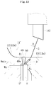
- FIG. 1 is a view for illustrating the entire structure of a drive shaft 1 using an outer joint member 11 according to the first embodiment.
- the drive shaft 1 mainly comprises a plunging type constant velocity universal joint 10 arranged on a differential side (right side of FIG. 1 : hereinafter also referred to as "inboard side"), a fixed type constant velocity universal joint 20 arranged on a driving wheel side (left side of FIG. 1 : hereinafter also referred to as "outboard side”), and an intermediate shaft 2 configured to couple both the constant velocity universal joints 10 and 20 to allow torque transmission therebetween.
- the plunging type constant velocity universal joint 10 illustrated in FIG. 1 is a so-called double-offset type constant velocity universal joint (DOJ).
- the constant velocity universal joint 10 comprises the outer joint member 11 comprising a cup section 12 and a long shaft section (hereinafter referred to also as "long stem section") 13 that extends from a bottom portion of the cup section 12 in an axial direction, an inner joint member 16 housed along an inner periphery of the cup section 12 of the outer joint member 11, balls 41 serving as torque transmitting elements that are arranged between track grooves 30 and 40 of the outer joint member 11 and the inner joint member 16, and a cage 44 having a spherical outer peripheral surface 45 and a spherical inner peripheral surface 46 that are fitted to a cylindrical inner peripheral surface 42 of the outer joint member 11 and a spherical outer peripheral surface 43 of the inner joint member 16, respectively, and being configured to retain the balls 41.
- a curvature center O 1 of the spherical outer peripheral surface 45 and a curvature center O 2 of the spherical inner peripheral surface 46 of the cage 44 are offset equidistantly from a joint center O toward opposite sides in the axial direction.
- An inner ring of a support bearing 6 is fixed to an outer peripheral surface of the long stem section 13, and an outer ring of the support bearing 6 is fixed to a transmission case with a bracket (not shown).
- the outer joint member 11 is supported by the support bearing 6 in a freely rotatable manner, and when the support bearing 6 as described above is provided, vibration of the outer joint member 11 during driving or the like is prevented as much as possible.
- the fixed type constant velocity universal joint 20 illustrated in FIG. 1 is a so-called Rzeppa type constant velocity universal joint, and comprises an outer joint member 21 comprising a bottomed cylindrical cup section 21a and a shaft section 21b that extends from a bottom portion of the cup section 21a in the axial direction, an inner joint member 22 housed along an inner periphery of the cup section 21a of the outer joint member 21, balls 23 serving as torque transmitting elements that are arranged between the cup section 21a of the outer joint member 21 and the inner joint member 22, and a cage 24, which is arranged between an inner peripheral surface of the cup section 21a of the outer joint member 21 and an outer peripheral surface of the inner joint member 22, and is configured to retain the balls 23.
- an undercut-free type constant velocity universal joint may sometimes be used as the fixed type constant velocity universal joint 20.
- the intermediate shaft 2 comprises splines 3 for torque transmission (including serrations; the same applies hereinafter) at outer peripheries on both end portions thereof.
- the spline 3 on the inboard side is spline-fitted to a hole portion of the inner joint member 16 of the plunging type constant velocity universal joint 10.
- the intermediate shaft 2 and the inner joint member 16 of the plunging type constant velocity universal joint 10 are coupled to each other to allow torque transmission therebetween.
- the spline 3 on the outboard side is spline-fitted to a hole portion of the inner joint member 22 of the fixed type constant velocity universal joint 20.
- the intermediate shaft 2 and the inner joint member 22 of the fixed type constant velocity universal joint 20 are coupled to each other to allow torque transmission therebetween.
- the solid intermediate shaft 2 is illustrated, a hollow intermediate shaft may be used instead.
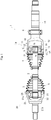
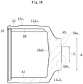
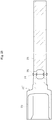
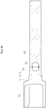
- FIGS. 2 are enlarged views for illustrating the outer joint member 11 according to this embodiment.
- FIG. 2a is a partial vertical sectional view.
- FIG. 2b is an enlarged view for illustrating a circle "A" of FIG. 2a.
- FIG. 2c is a view for illustrating a shape before welding.
- the outer joint member 11 comprises the bottomed cylindrical cup section 12 that is opened at one end and has the cylindrical inner peripheral surface 42 and the plurality of track grooves 30, on which the balls 41 (see FIG.
- the outer joint member 11 is formed by welding a cup member 12a and a shaft member 13a to each other.
- the cup member 12a illustrated in FIG. 2a to FIG. 2c is an integrally-formed product being made of medium carbon steel, such as S53C, containing carbon of from 0.40 wt% to 0.60 wt%, and having a cylindrical portion 12a1 and a bottom portion 12a2.
- the cylindrical portion 12a1 has the track grooves 30 and the cylindrical inner peripheral surface 42 formed at an inner periphery thereof.
- a projecting portion 12a3 is formed at the bottom portion 12a2 of the cup member 12a.
- a boot mounting groove 32 is formed at an outer periphery of the cup member 12a on the opening side thereof, whereas a snap ring groove 33 is formed at an inner periphery of the cup member 12a on the opening side thereof.
- a bearing mounting surface 14 and a snap ring groove 15 are formed at an outer periphery of the shaft member 13a on the cup member 12a side, whereas the spline Sp is formed at an end portion of the shaft member 13a on an opposite side.
- the shaft member 13a is made of medium carbon steel, such as S40C, containing carbon of from 0.30 wt% to 0.55 wt%.
- a joining end surface 50 formed at the projecting portion 12a3 of the bottom portion 12a2 of the cup member 12a and a joining end surface 51 formed at an end portion of the shaft member 13a on the cup member 12a side are brought into abutment against each other, and are welded to each other by electron beam welding performed from an outer side of the cup member 12a in a radial direction.
- a welded portion 49 is formed of a bead, which is formed by a beam radiated from a radially outer side of the cup member 12a.
- outer diameters B of the joining end surface 50 and the joining end surface 51 are set to equal dimensions for each joint size.
- the outer diameter B of the joining end surface 50 of the cup member 12a and the outer diameter B of the joining end surface 51 of the shaft member 13a need not be set to equal dimensions.
- a dimensional difference may be given as appropriate in such a manner that the outer diameter B of the joining end surface 51 is set slightly smaller than the outer diameter B of the joining end surface 50 (the dimensional relationship between the outer diameter B of the joining end surface 50 and the outer diameter B of the joining end surface 51 is consistent throughout specification.
- the welded portion 49 is formed on the joining end surface 51 located on the cup member 12a side with respect to the bearing mounting surface 14 of the shaft member 13a, and hence the bearing mounting surface 14 and the like can be processed in advance so that post-processing after welding can be omitted. Further, due to the electron beam welding, burrs are not generated at the welded portion. Thus, post-processing for the welded portion can also be omitted, which can reduce manufacturing cost. Still further, total inspection on the welded portion through ultrasonic flaw detection can be performed.
- features of this embodiment reside in an ultrasonic flaw detection-inspection method and a shape of the welded portion, which are capable of enhancing accuracy and operability in inspection on the welded portion in order to practically achieve the novel manufacturing concept for the outer joint member of the constant velocity universal joint being a mass-produced product. Details thereof are described later.
- an inner diameter D of the joining end surface 50 of the cup member 12a is set smaller than an inner diameter E of the joining end surface 51 of the shaft member 13a.
- a protruding surface 50a protruding to a radially inner side with respect to the inner diameter E of the joining end surface 51 of the shaft member 13a is formed. In such a state, the cup member 12a and the shaft member 13a are welded to each other.
- the protruding surface 50a is formed into the same shape for each joint size.
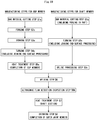
- FIG. 3 is an illustration of the overview of the manufacturing steps for the outer joint member.
- the cup member 12a is manufactured through manufacturing steps comprising a bar material cutting step S1c, a forging step S2c, an ironing step S3c, and a turning step S4c.
- the shaft member 13a is manufactured through manufacturing steps comprising a bar material cutting step S1s, a turning step S2s, and a spline processing step S3s. Intermediate components of the cup member 12a and the shaft member 13a thus manufactured are each assigned with a product number for management.
- a machining step described in Claims refers to the turning step S4c and the turning step S2s among the above-mentioned manufacturing steps, and to a grinding step S5s described later (see FIG. 20 ).
- a bar material is cut into a predetermined length in accordance with a forging weight, thereby producing a billet.
- the billet is subjected to forging so as to integrally form the cylindrical portion, the bottom portion, and the projecting portion as a preform of the cup member 12a.
- Ironing is performed on the track grooves 30 and the cylindrical inner peripheral surface 42 of the preform, thereby finishing the inner periphery of the cylindrical portion of the cup member 12a.
- the outer peripheral surface, the boot mounting groove 32, the snap ring groove 33 and the like, and the joining end surface 50 are formed by turning.
- the cup member 12a in the form of an intermediate component is assigned with a product number for management.
- a bar material is cut into a predetermined length in accordance with the total length of the shaft section, thereby producing a billet.
- the billet may be forged into a rough shape by upset forging depending on the shape of the shaft member 13a.
- the outer peripheral surface of the billet (bearing mounting surface 14, snap ring groove 15, minor diameter of the spline, end surface, and the like) and the joining end surface 51 of the billet at the end portion on the cup member 12a side are formed by turning.
- the spline is formed by rolling in the shaft member after turning.
- the method of processing the spline is not limited to the rolling, but press working or the like may be adopted instead as appropriate.
- the shaft member 13a in the form of an intermediate component is assigned with a product number for management.
- the joining end surface 50 of the cup member 12a and the joining end surface 51 of the shaft member 13a are brought into abutment against and welded to each other.
- the welded portion 49 between the cup member 12a and the shaft member 13a is inspected by the ultrasonic flaw-detection method.
- Induction quenching and tempering are performed as heat treatment on at least the track grooves 30 and the cylindrical inner peripheral surface 42 of the cup section 12 after welding and a necessary range of the outer periphery of the shaft section 13 after welding. Heat treatment is not performed on the welded portion.
- a hardened layer having a hardness of approximately from 58 HRC to 62 HRC is formed on each of the track grooves 30 and the cylindrical inner peripheral surface 42 of the cup section 12. Further, a hardened layer having a hardness of approximately from 50 HRC to 62 HRC is formed in a predetermined range of the outer periphery of the shaft section 13.
- the heat treatment step is provided after the welding step, and hence the manufacturing steps are suited to a cup member and a shaft member having such shapes and specifications that the hardness of the heat-treated portion may be affected by temperature rise at the periphery due to heat generated during the welding.
- FIG. 4a is a vertical sectional view for illustrating a state after ironing of the cup member 12a.
- FIG. 4b is a vertical sectional view for illustrating a state after turning.
- a preform 12a' for the cup member 12a a cylindrical portion 12a1', a bottom portion 12a2', and a projecting portion 12a3' are integrally formed in the forging step S2c.
- the track grooves 30 and the cylindrical inner peripheral surface 42 are formed by ironing in the ironing step S3c so that the inner periphery of the cylindrical portion 12a1' is finished as illustrated in FIG. 4a .
- the outer peripheral surface, the boot mounting groove 32, the snap ring groove 33, and the like of the cup member 12a as well as the joining end surface 50 of the projecting portion 12a3 of the bottom portion 12a2 and the joining end surface 50 having the outer diameter B and the inner diameter D are formed by turning as illustrated in FIG. 4b .
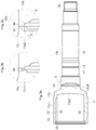
- FIGS. 5 are illustrations of states of the shaft member 13a in the respective processing steps.
- FIG. 5a is a front view for illustrating a billet 13a" obtained by cutting a bar material.
- FIG. 5b is a partial vertical sectional view for illustrating a preform 13a' obtained by forging the billet 13a" into a rough shape by upset forging.
- FIG. 5c is a partial vertical sectional view for illustrating the shaft member 13a after turning and spline processing.
- the billet 13a" illustrated in FIG. 5a is produced in the bar material cutting step S1s.
- the preform 13a' is produced by increasing, if necessary, the shaft diameter of the billet 13a" in a predetermined range and forming a recessed portion 52 at a joining-side end portion (end portion on the cup member 12a side) by upset forging as illustrated in FIG. 5b .
- the outer diameter of the shaft member 13a, the bearing mounting surface 14, the snap ring groove 15, an inner diameter portion 53 (inner diameter E) of the recessed portion 52, the joining end surface 51, and the joining end surface 50 having the outer diameter B are formed by turning as illustrated in FIG. 5c .
- the spline processing step S3s the spline Sp is processed at the end portion on the opposite side to the recessed portion 52 by rolling or press forming.
- the outer diameter B of the joining end surface 50 located at the projecting portion 12a3 of the bottom portion 12a2 of the cup member 12a illustrated in FIG. 4b is set to an equal dimension for one joint size.
- the outer diameter B of the joining end surface 51 located at the end portion on the cup member 12a side is set to an equal dimension to the outer diameter B of the joining end surface 50 of the cup member 12a irrespective of the shaft diameter and the outer peripheral shape.
- the joining end surface 51 of the shaft member 13a is located at the position on the cup member 12a side with respect to the bearing mounting surface 14.
- the outer joint member 11 compatible with various vehicle types can be manufactured in such a manner that, while the cup member 12a is prepared for common use, only the shaft member 13a is manufactured to have a variety of shaft diameters, lengths, and outer peripheral shapes depending on vehicle types, and both the members 12a and 13a are welded to each other. Details of the preparation of the cup member 12a for common use are described later.
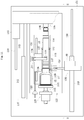
- FIG. 6 and FIG. 7 are views for illustrating an overview of a welding apparatus.
- FIG. 6 is an illustration of a state before welding.
- FIG. 7 is an illustration of a state during welding.
- a welding apparatus 100 mainly comprises an electron gun 101, a rotation device 102, a chuck 103, a center hole guide 104, a tailstock 105, workpiece supports 106, a center hole guide 107, a case 108, and a vacuum pump 109.
- the cup member 12a and the shaft member 13a being workpieces are placed on the workpiece supports 106 arranged inside the welding apparatus 100.
- the chuck 103 and the center hole guide 107 arranged at one end of the welding apparatus 100 are coupled to the rotation device 102.
- the chuck 103 grips the cup member 12a to rotate the cup member 12a under a state in which the center hole guide 107 has centered the cup member 12a.
- the center hole guide 104 is integrally mounted to the tailstock 105 arranged at the other end of the welding apparatus 100. Both the center hole guide 104 and the tailstock 105 are configured to reciprocate in the axial direction (lateral direction of FIG. 7 ).
- a center hole of the shaft member 13a is set on the center hole guide 104 so that the shaft member 13a is centered.
- the vacuum pump 109 is connected to the case 108 of the welding apparatus 100.
- a "sealed space" herein refers to a space 111 defined by the case 108.
- the cup member 12a and the shaft member 13a are entirely received in the sealed space 111.
- the electron gun 101 is arranged at a position corresponding to the joining end surfaces 50 and 51 of the cup member 12a and the shaft member 13a.
- the electron gun 101 is configured to approach the workpieces up to a predetermined position.
- the cup member 12a and the shaft member 13a being workpieces are stocked at a place different from the place of the welding apparatus 100.
- the respective workpieces are taken out by, for example, a robot, are conveyed into the case 108 of the welding apparatus 100 opened to the air as illustrated in FIG. 6 , and are set at predetermined positions on the workpiece supports 106.
- the center hole guide 104 and the tailstock 105 are retreated to the right side of FIG. 6 , and hence a gap is formed between the joining end surfaces 50 and 51 of the cup member 12a and the shaft member 13a.
- the center hole guide 104 and the tailstock 105 are advanced to the left side as illustrated in FIG. 7 to eliminate the gap between the joining end surfaces 50 and 51 of the cup member 12a and the shaft member 13a.
- the cup member 12a is centered by the center hole guide 107 and fixed by the chuck 103, whereas the shaft member 13a is supported by the center hole guide 104.
- the workpiece supports 106 are moved away from the workpieces.
- the distance between the workpiece supports 106 and the workpieces may be infinitesimal, and hence illustration of this distance is omitted from FIG. 7 .
- the welding apparatus 100 may have such a structure that the workpiece supports 106 are retreated downward greatly.
- the electron gun 101 is then caused to approach the workpieces up to a predetermined position and the workpieces are rotated to start pre-heating.
- a pre-heating condition unlike the welding condition, the temperature is set lower than the welding temperature by, for example, radiating an electron beam under a state in which the electron gun 101 is caused to approach the workpieces so as to increase the spot diameter.
- the cooling rate after welding is reduced, thereby being capable of preventing a quenching crack.
- the electron gun 101 is retreated to a predetermined position, and radiates the electron beam from the outer side of the workpieces in the radial direction to start welding.
- the electron gun 101 is retreated and the rotation of the workpieces is stopped.
- the sealed space 111 is then opened to the air. Then, the center hole guide 104 and the tailstock 105 are retreated to the right side and the chuck 103 is opened under a state in which the workpiece supports 106 are raised to support the workpieces. After that, for example, the robot grips the workpieces, takes the workpieces out of the welding apparatus 100, and places the workpieces into alignment on a cooling stocker. In this embodiment, the cup member 12a and the shaft member 13a are entirely received in the sealed space 111, and hence the configuration of the sealed space 111 defined in the case 108 can be simplified.
- the cup member 12a having a carbon content of from 0.4% to 0.6% and the shaft member 13a having a carbon content of from 0.3% to 0.55% were used and welded to each other in the above-mentioned welding apparatus 100 under the condition that the pressure in the sealed space 111 defined in the case 108 was set to 6.7 Pa or less.
- the joining end surfaces 50 and 51 of the cup member 12a and the shaft member 13a were soaked by pre-heating to have a temperature of from 300°C to 650°C, and then electron beam welding was performed.
- FIG. 8 is a front view for illustrating an overview of an ultrasonic flaw detection-inspection apparatus as viewed from the arrow G-G of FIG. 9.
- FIG. 9 is a plan view for illustrating the ultrasonic flaw detection-inspection apparatus.
- the outer joint member after welding is placed in the ultrasonic flaw detection-inspection apparatus.
- FIG. 10 is a front view for illustrating a state during inspection as viewed from the arrow H-H of FIG. 11.
- FIG. 11 is a plan view for illustrating the state during inspection.
- an ultrasonic flaw detection-inspection apparatus 120 mainly comprises a water bath 122 mounted at the center of a base 121, a workpiece support 123, a workpiece holding member 124, a rotary drive device 125 configured to rotate an intermediate product 11' of the outer joint member 11 (hereinafter also referred to as "workpiece 11'"), a pressing device 135 configured to press an axial end of the workpiece 11', and a drive positioning device 136 (see FIG. 9 ) for a probe.
- the workpiece support 123 comprises rollers 126 and 127 configured to allow the workpiece 11' to be placed thereon in a freely rotatable manner.
- the rollers 126 and 127 are arranged in pairs so that the shaft section 13 of the workpiece 11' can be stably supported.
- the rollers 126 are located at a portion close to the welded portion, and the rollers 127 are located at a center portion of the shaft section 13.
- the rollers 126 and 127 are capable of adjusting the placement position of the workpiece 11' as appropriate in the axial direction (lateral direction of FIG. 9 ) and the radial direction (vertical direction of FIG. 9 ) in consideration of a joint size, dimensions, and weight balance of the workpiece 11'.
- the workpiece holding member 124 is mounted to the workpiece support 123 at a position displaced from an axial line of the workpiece 11' in a horizontal direction (see FIG. 9 ).
- the workpiece holding member 124 comprises a lever 128, and a workpiece holding roller 129 is arranged at an end portion of the lever 128.
- the lever 128 is pivotable in the plane, and is vertically movable.
- the workpiece support 123 is mounted to a support 134 through intermediation of a linear-motion bearing 130 comprising rails 131 and linear guides 132, and is movable in the axial direction (lateral direction of FIG. 8 and FIG. 9 ).
- the support 134 is mounted to the base 121.
- a rod 133 is coupled to an end portion (left end portion of FIG. 8 and FIG. 9 ) of the workpiece support 123 so that the workpiece support 123 is driven to be positioned by an actuator (not shown) on an outside of the water bath 122.
- the rotary drive device 125 comprises a rotary shaft 143 having a rotary disc 144 mounted thereto, and this rotary shaft 143 is driven to rotate by a motor (not shown) on the outside of the water bath 122.
- a mounting base 137 is arranged on an upper side of the ultrasonic flaw detection-inspection apparatus 120.
- a base plate 145 for the pressing device 135 configured to press the axial end of the workpiece 11' is mounted to the mounting base 137 through intermediation of a linear-motion bearing 138 comprising a rail 139 and a linear guide 140 so that the pressing device 135 is movable in the axial direction (lateral direction of FIG. 8 and FIG. 9 ).
- a rod 142 of a pneumatic cylinder 141 is coupled to an end portion of the base plate 145 for the pressing device 135 so that the pressing device 135 is driven.
- a free bearing 146 is mounted to a portion to be held in abutment against the axial end of the shaft section 13 of the workpiece 11' so that the axial end can be pressed in a freely rotatable manner.
- the drive positioning device 136 for a probe is arranged at a position displaced from the axial line of the workpiece 11' in a horizontal direction.
- This drive positioning device 136 comprises actuators for the X-axis direction (lateral direction of FIG. 9 ) and the Y-axis direction (vertical direction of FIG. 9 ) so that a probe 147 is driven to be positioned in the X-axis and Y-axis directions.
- An actuator 148 for the X-axis direction and an actuator 149 for the Y-axis direction are each an electric ball-screw type (electric cylinder), which is capable of performing positioning with high accuracy.
- Reference symbol 150 represents a rail for a linear-motion bearing.
- the drive positioning device 136 is arranged on the outside of the water bath 122, and the probe 147 and a holder 151 therefor are arranged in the water bath 122.
- the operation of the ultrasonic flaw detection-inspection apparatus 120 and the ultrasonic flaw detection-inspection step S6k are described.
- the workpiece 11' after welding is placed on the workpiece support 123 by a loading device (not shown).
- the workpiece support 123 is located at an appropriate interval from the rotary drive device 125 in the axial direction of the workpiece 11', and the workpiece holding member 124 raises and pivots the lever 128 thereof so as to be substantially parallel to the axial line of the workpiece 11'.
- the pressing device 135 and the drive positioning device 136 for a probe wait at retreated positions.
- the lever 128 of the workpiece holding member 124 is pivoted so as to be substantially perpendicular to the axial line of the workpiece 11', and then lowered to hold the workpiece 11' from above (see FIG. 10 ). Then, water is supplied to the water bath 122.
- flaw detection is performed under water, and hence ultrasonic waves are satisfactorily propagated. Thus, inspection can be performed with high accuracy.
- the pneumatic cylinder 141 is driven to cause the pressing device 135 to be advanced and pressed against the axial end of the workpiece 11', thereby pressing the opening rim of the cup section 12 of the workpiece 11' against the rotary disc 144 of the rotary drive device 125.
- the workpiece support 123 is also moved toward the rotary drive device 125.
- the workpiece 11' is positioned in the radial direction and the axial direction.
- the motor (not shown) of the rotary drive device 125 is rotated, thereby rotating the workpiece 11'.
- the drive positioning device 136 is moved in the X-axis direction, and then moved in the Y-axis direction, thereby positioning the probe 147 at a flaw detection position (in FIG. 10 , the probe 147 in this state is indicated by the broken line). Then, the flaw-detection inspection is performed. After the flaw-detection inspection, the water is drained, and the workpiece 11' is unloaded from the ultrasonic flaw detection-inspection apparatus 120 by the loading device (not shown). As described above, the inspection is sequentially repeated on the workpieces 11'.
- ultrasonic flaw detection-inspection apparatus 120 in order to reduce the cycle time of the inspection, time-consuming supply and drainage of water are performed simultaneously with the operations of the devices and the members, or at other timings in accordance therewith. Further, some of the operations of the devices and the members may be performed simultaneously with each other or in different orders as appropriate.
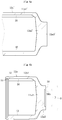
- FIG. 12a is an illustration of a non-defective welded product
- FIG. 12b is an illustration of a defective welded product
- FIG. 13 is an illustration of findings in the course of development.
- the probe 147 is positioned at the flaw detection position away from the welded portion 49 by a predetermined distance.
- the flaw detection position is preset for each joint size.
- a target welding depth is denoted by the reference symbol Wa
- a minimum acceptable welding depth is denoted by the reference symbol Wmin.
- Workpieces having a depth equal to or larger than the minimum acceptable welding depth Wmin are determined as non-defective welded products, and workpieces having a depth smaller than the minimum acceptable welding depth Wmin are determined as defective welded products.
- the ultrasonic flaw-detection inspection of this embodiment is performed under the condition that the incident angle ⁇ 1 is approximately 20°, and the refraction angle ⁇ 2 is approximately 45°.
- the workpiece 11' is kept rotated by the rotary drive device 125 (see FIG. 10 ).
- the probe 147 positioned at the flaw detection position away from the welded portion 49 by the predetermined distance collects data of the entire periphery of the workpiece 11'. Specifically, in consideration of tolerance for displacement of the welding position, at the above-mentioned flaw detection position, first, data of a single rotation (360°) of the workpiece 11' is collected. Then, the probe 147 is sequentially shifted in the axial direction at a minute pitch (for example, 0.5 mm) to collect data of a plurality of rotations (for example, five rotations). Based on those pieces of data, non-defective/defective determination is made. A threshold of a reflected echo to be used in the non-defective/defective determination is determined based on a welding pattern corresponding to the minimum acceptable welding depth Wmin.
- the inner diameter D of the joining end surface 50 of the cup member 12a is set smaller than the inner diameter E of the joining end surface 51 of the shaft member 13a.
- the protruding surface 50a protruding to the radially inner side with respect to the inner diameter E of the joining end surface 51 of the shaft member 13a is formed. In such a state, the cup member 12a and the shaft member 13a are welded to each other.
- the transmission pulse G from the probe 147 when the transmission pulse G from the probe 147 is input as illustrated in FIG. 12a , the transmission pulse G enters the cup section 12 through a back bead 49a at the depth equal to or larger than the minimum acceptable welding depth Wmin, and travels straight as it is.
- the transmission pulse G is transmitted to the cup section 12 side by being reflected due to the inner diameter D of the cup section 12. In those cases, the probe 147 does not receive a reflected echo.
- an inner diameter D' of the joining end surface 50 of the cup member 12a is set to an equal dimension to the inner diameter E of the joining end surface 51 of the shaft member 13a.
- this non-defective welded product which has a welding depth equal to or larger than the minimum acceptable welding depth Wmin, when the transmission pulse G from the probe 147 is input, due to the boundary surface of the back bead 49a, which is perpendicular to the transmission pulse G, a reflected echo R reflected by this boundary surface is received by the probe 147.
- the inventors of the present invention arrived at the shape of the welded portion of this embodiment.
- Q is a height of the back bead 49a from the inner diameter E of the joining end surface 51 as illustrated in FIG. 12a .
- the ultrasonic flaw detection-inspection apparatus 120 mainly comprises the water bath 122 mounted at the center of the base 121.
- the workpiece support 123, the workpiece holding member 124, the rotary disc 144 of the rotary drive device 125 configured to rotate the workpiece 11', the free bearing 146 of the pressing device 135 configured to press the axial end of the workpiece 11', and the probe 147 mounted to the drive positioning device 136 are arranged.
- the operation of loading the workpiece 11', the supply and drainage of water, the flaw-detection inspection, and the operation of unloading the workpiece 11' can be performed in conjunction with each other, and the ultrasonic flaw-detection inspection can be automated.
- accuracy, operability, and efficiency in the inspection can be enhanced, which is suited to the inspection on the welded portion of the outer joint member of the constant velocity universal joint being a mass-produced product.
- the outer diameter B of the joining end surface 50 of the cup member 12a of this embodiment is set to an equal dimension for each joint size. Also with this base configuration, in the ultrasonic flaw-detection inspection, setup operations with respect to the outer joint members 11 having the different product numbers are simplified. Thus, the efficiency in the inspection can be further enhanced.
- flaw detection is performed under water, and hence ultrasonic waves are satisfactorily propagated.
- inspection can be performed with much higher accuracy.
- the shape of the welded portion in which the protruding surface 50a is formed on the joining end surface 50, the intensities of the reflected echoes can clearly be discriminated from each other.
- the determination as to whether the welded product is non-defective or defective can be made with high accuracy.
- a shaft member 13b illustrated in FIG. 14 and FIG. 15 is used as a general stem type on the inboard side.
- the shaft member 13b has the joining end surface 51 to be brought into abutment against the joining end surface 50 (see FIG. 4b ) of the bottom portion 12a2 (projecting portion 12a3) of the cup member 12a.
- the outer diameter B and the inner diameter E of the joining end surface 51 are set to the equal dimensions to the outer diameter B and the inner diameter E of the joining end surface 51 of the shaft member 13a of the long stem type illustrated in FIGS. 5 .
- the inner diameter D of the joining end surface 50 of the cup member 12a is set smaller than the inner diameter E of the joining end surface 51 of the shaft member 13b.
- the protruding surface 50a protruding to the radially inner side with respect to the inner diameter E of the joining end surface 51 of the shaft member 13b is formed. In such a state, the cup member 12a and the shaft member 13b are welded to each other.
- the shaft member 13b is used as the general stem type on the inboard side. Accordingly, the shaft member 13b comprises a shaft section with a small length, and a sliding bearing surface 18 formed on an axial center portion thereof, and a plurality of oil grooves 19 are formed in the sliding bearing surface 18.
- the spline Sp and a snap ring groove 48 are formed in an end portion of the shaft member 13b on the side opposite to the cup member 12a side.
- the diameter B of the joining end surface 51 of the shaft member 13a or 13b is set to an equal dimension.
- the outer diameter B of the joining end surface 50 of the cup member 12a and the joining end surface 51 of the shaft member 13a or 13b is set to an equal dimension for each joint size.
- the cup member prepared for common use for each joint size, and the shaft member having a variety of specifications of the shaft section for each vehicle type can be prepared in a state before heat treatment.
- the intermediate component of each of the cup member 12a and the shaft member 13a or 13b can be assigned with a product number for management.
- various types of the outer joint members 11 satisfying requirements can be produced quickly through combination of the cup member 12a and the shaft member 13a or 13b having a variety of specifications of the shaft section for each vehicle type. Therefore, standardization of a product type of the cup member 12a can reduce cost and alleviate a burden of production management.
- the standardization of the product type of the cup member is described above by taking the differences in types, such as the general length stem type and the long stem type, as an example for easy understanding, but the present invention is not limited thereto.
- FIG. 16 is a diagram for illustrating an example of standardization of a product type of the cup member according to this embodiment.
- the cup member is prepared for common use for one joint size, and is assigned with, for example, a product number C001 for management.
- the shaft member has a variety of specifications of the shaft section for each vehicle type, and is assigned with, for example, a product number S001, S002, or S(n) for management.
- the outer joint member assigned with a product number A001 can be produced.
- the cup member is not limited to one type for one joint size, that is, not limited to one type assigned with a single product number.
- the cup member comprises cup members of a plurality of types (assigned with a plurality of product numbers, respectively) that are prepared for one joint size based on different specifications of a maximum operating angle, and are each prepared so that the outer diameter B of the joining end surface of each of those cup members has an equal dimension.
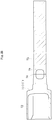
- FIG. 17a is a partial vertical sectional view for illustrating an outer joint member of this modification
- FIG. 17b is an enlarged view for illustrating a circle "A" of FIG. 17a
- FIG. 17c is a view for illustrating a state before welding in FIG. 17b
- FIG. 18 is a vertical sectional view for illustrating the entirety of a cup member before welding.
- a form of a protruding surface formed on a joining end surface of the cup member of this modification is different from that in the first embodiment, and other features are the same as those in the first embodiment.
- parts that have the same function are denoted by the same reference symbols (except for the subscripts), and only main points are described.
- a joining end surface 50 1 formed on a projecting portion 12 1 a3 of a bottom portion 12 1 a2 of a cup member 12 1 a is formed by annular turning.
- a diameter D 1 of the joining end surface 50 1 on the radially inner side corresponds to the inner diameter D of the joining end surface 50 of the cup member 12a of the first embodiment.
- a portion on the radially inner side with respect to the inner diameter E of the shaft member 13a corresponds to a protruding surface 50 1 a.
- the cup member 12 1 a of this modification can be formed by turning an end surface of the projecting portion 12a3' of the preform 12a' for the above-mentioned cup member after ironing, which is illustrated in FIG. 4a , at only a portion corresponding to the joining end surface 50 1 on the radially outer side as illustrated in FIG. 18 .
- the time for the turning can be reduced.
- the present invention is not limited thereto, and a projecting surface portion 50b 1 of the joining end surface on the radially inner side of FIG. 18 may be subjected to turning.
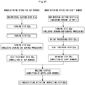
- FIG. 19 is an illustration of a manufacturing method according to a second embodiment of the present invention.
- the heat treatment step for the cup member which is involved in the heat treatment step S7 in FIG. 3 as described above in the first embodiment, is provided before the welding step S6 in the sequence and named "heat treatment step S5c", to thereby prepare the cup member as a finished product.
- the cup member 12a has a shape extending from the joining end surface 50 to the large-diameter cylindrical portion 12a1 via the bottom portion 12a2, and the portions to be subjected to heat treatment that involves quenching and tempering are the track grooves 30 and the cylindrical inner peripheral surface 42 located at the inner periphery of the cylindrical portion 12a1. Therefore, the cup member 12a generally has no risk of thermal effect on the heat-treated portion during the welding. For this reason, the cup member 12a is subjected to heat treatment before the welding to be prepared as a finished component. The manufacturing steps of this embodiment are suitable in practical use.
- the cup member 12a is subjected to heat treatment for preparing the cup member 12a as a finished product, and is therefore assigned with a product number indicating a finished product for management.
- the standardization of the product type of the cup member 12a remarkably reduces the cost and alleviates the burden of production management.
- the cup member 12a can be manufactured solely until the cup member 12a is completed as a finished product through the forging, turning, and heat treatment.
- the productivity is enhanced by virtue of reduction of setups and the like as well.
- FIG. 16 for illustrating the example of standardization of the product type of the cup member as described above in the first embodiment, only the product number of the cup member in FIG. 16 is changed to the product number indicating a finished product, whereas the product numbers of the shaft member and the outer joint member are the same as those of the first embodiment. Therefore, description thereof is omitted herein.
- FIG. 20 is an illustration of a manufacturing method according to a third embodiment of the present invention.
- the heat treatment steps for the cup section and the shaft section which are involved in the heat treatment step S7 in FIG. 3 as described above in the first embodiment, and the grinding step S8 for the shaft section in FIG. 3 are provided before the welding step S6 in the sequence and named "heat treatment step S5c for cup member", “heat treatment step S4s for shaft member”, and "grinding step S5s".
- both the cup member and the shaft member are prepared as finished products.
- a hardened layer having a hardness of approximately from 50 HRC to 62 HRC is formed in a predetermined range of the outer peripheral surface of the shaft member by induction quenching in the heat treatment step S4s.
- Heat treatment is not performed on a predetermined portion in the axial direction, which includes the joining end surface 51.
- the heat treatment for the cup member, the assignment of the product number, and the like are the same as those of the second embodiment on the manufacturing method, and redundant description is therefore omitted herein.
- the shaft member is transferred to the grinding step S5s so that the bearing mounting surface 14 and the like are finished.
- the shaft member is obtained as a finished product.
- the shaft member is assigned with a product number indicating a finished product for management.
- the manufacturing steps of this embodiment are suitable in a case of a cup member and a shaft member having shapes and specifications with no risk of thermal effect on the heat-treated portion during the welding.
- both the cup member and the shaft member can be assigned with product numbers indicating finished products for management.
- the standardization of the product type of the cup member further remarkably reduces the cost and alleviates the burden of production management.
- the cup member and the shaft member can be manufactured independently of each other until the cup member and the shaft member are completed as finished products through the forging, turning, heat treatment, grinding after heat treatment, and the like.
- the productivity is further enhanced by virtue of reduction of setups and the like as well.
- the product numbers of the cup member and the shaft member in FIG. 16 are changed to the product numbers indicating finished products.
- the product number of the outer joint member is the same as that of the first embodiment. Therefore, description thereof is omitted herein.
- the cup member and the shaft member to be prepared as finished components are not limited to the cup member and the shaft member subjected to finishing such as the above-mentioned grinding after heat treatment or cutting after quenching, but encompass a cup member and a shaft member in a state in which the heat treatment is completed while the finishing is uncompleted.
- the cup member is not limited to one type for one joint size, that is, not limited to one type assigned with a single product number.
- the cup member encompasses, for example, cup members of a plurality of types (assigned with a plurality of product numbers, respectively) that are prepared for one joint size based on different specifications of a maximum operating angle, and are also prepared so that the outer diameters B of the above-mentioned joining end surfaces of the cup members are set to equal dimensions.
- the cup member encompasses, for example, cup members of a plurality of types (assigned with a plurality of product numbers, respectively) that are prepared for one joint size in order to achieve management of the cup members in a plurality of forms including intermediate components before heat treatment and finished components in consideration of the joint function, the circumstances at the manufacturing site, the productivity, and the like, and are also prepared so that the outer diameters B of the above-mentioned joining end surfaces of the cup members are set to equal dimensions.
- FIG. 21 and FIG. 22 parts that have the same function as those of the outer joint member according to the first embodiment are denoted by the same reference symbols, and only main points are described.
- a plunging type constant velocity universal joint 10 2 illustrated in FIG. 21 is a tripod type constant velocity universal joint (TJ), and comprises an outer joint member 11 2 comprising a cup section 12 2 and the long stem section 13 that extends from a bottom portion of the cup section 12 2 in the axial direction, an inner joint member 16 2 housed along an inner periphery of the cup section 12 2 of the outer joint member 11 2 , and rollers 19 serving as torque transmitting elements that are arranged between the outer joint member 11 2 and the inner joint member 16 2 .
- the inner joint member 16 2 comprises a tripod member 17 comprising three equiangular leg shafts 18 on which the rollers 19 are externally fitted.
- the inner ring of the support bearing 6 is fixed to the outer peripheral surface of the long stem section 13, and the outer ring of the support bearing 6 is fixed to the transmission case with the bracket (not shown).
- the outer joint member 11 2 is supported by the support bearing 6 in a freely rotatable manner, and thus the vibration of the outer joint member 11 2 during driving or the like is prevented as much as possible.
- FIG. 22 is a partial vertical sectional view for illustrating the outer joint member 11 2 .
- the outer joint member 11 2 comprises a bottomed cylindrical cup section 12 2 that is opened at one end and has inner peripheral surfaces 31 2 and the track grooves 30 2 , on which the rollers 19 (see FIG. 21 ) are caused to roll, formed at three equiangular positions on an inner peripheral surface of the cup section 12 2 , and the long stem section 13 that extends from a bottom portion of the cup section 12 2 in the axial direction and comprises the spline Sp serving as the torque transmitting coupling portion formed at the outer periphery of the end portion on the opposite side to the cup section 12 2 side.
- the outer joint member 11 2 is formed by welding the cup member 12 2 a and the shaft member 13a to each other.
- the cup member 12 2 a is an integrally-formed product having a cylindrical portion 12 2 a1 and a bottom portion 12 2 a2.
- the cylindrical portion 12 2 a1 has the track grooves 30 2 and the inner peripheral surfaces 31 2 formed at the inner periphery thereof.
- a projecting portion 12 2 a3 is formed at the bottom portion 12 2 a2 of the cup member 12 2 a.
- the boot mounting groove 32 is formed at an outer periphery of the cup member 12 2 a on the opening side thereof.
- the bearing mounting surface 14 and the snap ring groove 15 are formed at the outer periphery of the shaft member 13a on the cup member 12 2 a side, whereas the spline Sp is formed at the end portion on the opposite side to the cup member 12 2 a side.
- a joining end surface 50 2 formed at the projecting portion 12 2 a3 of the bottom portion 12 2 a2 of the cup member 12 2 a and the joining end surface 51 formed at the end portion of the shaft member 13a on the cup member 12 2 a side are brought into abutment against each other, and are welded to each other by electron beam welding performed from the radially outer side.
- the welded portion 49 is formed of a bead, which is formed by a beam radiated from the radially outer side of the cup member 12 2 a.
- the outer diameters B of the joining end surface 50 2 and the joining end surface 51 are set to equal dimensions for each joint size.
- the welded portion 49 is formed on the joining end surface 51 located on the cup member 12 2 a side with respect to the bearing mounting surface 14 of the shaft member 13a, and hence the bearing mounting surface 14 and the like can be processed in advance so that post-processing after welding can be omitted. Further, due to the electron beam welding, burrs are not generated at the welded portion. Thus, post-processing for the welded portion can also be omitted, which can reduce the manufacturing cost.
- the details of the outer joint member according to this embodiment are the same as the details of the outer joint member according to the first embodiment, and the manufacturing method according to the first to third embodiments as described above. Therefore, all of those details are applied in this embodiment to omit redundant description.
- the case where the protruding surface is formed on the radially inner side with respect to the joining end surface of the cup member is exemplified.
- the protruding surface may be formed on the radially inner side with respect to the joining end surface of the shaft member. In this case, there are no problems as long as the ultrasonic flaw-detection inspection is performed from a surface side of the cup member.
- the present invention is applied to the double-offset type constant velocity universal joint as the plunging type constant velocity universal joint 10, and to the tripod type constant velocity universal joint as the plunging type constant velocity universal joint 10 are described.
- the present invention may be applied to an outer joint member of another plunging type constant velocity universal joint such as a cross-groove type constant velocity universal joint, and to an outer joint member of a fixed type constant velocity universal joint.
- the present invention is applied to the outer joint member of the constant velocity universal joint, which is used to construct the drive shaft.
- the present invention may be applied to an outer joint member of a constant velocity universal joint, which is used to construct a propeller shaft.
Landscapes
- Engineering & Computer Science (AREA)
- General Engineering & Computer Science (AREA)
- Mechanical Engineering (AREA)
- Physics & Mathematics (AREA)
- Pathology (AREA)
- Biochemistry (AREA)
- General Health & Medical Sciences (AREA)
- General Physics & Mathematics (AREA)
- Immunology (AREA)
- Chemical & Material Sciences (AREA)
- Life Sciences & Earth Sciences (AREA)
- Health & Medical Sciences (AREA)
- Analytical Chemistry (AREA)
- Optics & Photonics (AREA)
- Acoustics & Sound (AREA)
- Quality & Reliability (AREA)
- Plasma & Fusion (AREA)
- Welding Or Cutting Using Electron Beams (AREA)
- Pressure Welding/Diffusion-Bonding (AREA)
- Forging (AREA)
- Laser Beam Processing (AREA)
Description
- The present invention relates to a method of manufacturing an outer joint member of a constant velocity universal joint and an outer joint member.
- In a constant velocity universal joint, which is used to construct a power transmission system for automobiles and various industrial machines, two shafts on a driving side and a driven side are coupled to each other to allow torque transmission therebetween, and rotational torque can be transmitted at a constant velocity even when each of the two shafts forms an operating angle. The constant velocity universal joint is roughly classified into a fixed type constant velocity universal joint that allows only angular displacement, and a plunging type constant velocity universal joint that allows both the angular displacement and axial displacement. In a drive shaft configured to transmit power from an engine of an automobile to a driving wheel, for example, the plunging type constant velocity universal joint is used on a differential side (inboard side), and the fixed type constant velocity universal joint is used on a driving wheel side (outboard side).
- Irrespective of the plunging type and the fixed type, the constant velocity universal joint includes, as a main component, an outer joint member including a cup section having track grooves formed in an inner peripheral surface thereof and engageable with torque transmitting elements, and a shaft section that extends from a bottom portion of the cup section in an axial direction. In many cases, the outer joint member is constructed by integrally forming the cup section and the shaft section by subjecting a rod-like solid blank (bar material) to plastic working such as forging and ironing or processing such as cutting work, heat treatment, and grinding.
- Incidentally, as the outer joint member, an outer joint member including a long shaft section (long stem) may sometimes be used. In order to equalize lengths of a right part and a left part of an intermediate shaft, the long stem is used for an outer joint member on the inboard side that corresponds to one side of the drive shaft. The long stem is rotatably supported by a rolling bearing. Although varied depending on vehicle types, the length of the long stem section is approximately from 300 mm to 400 mm in general. In the outer joint member, the long shaft section causes difficulty in integrally forming the cup section and the shaft section with high accuracy. Therefore, there is known an outer joint member in which the cup section and the shaft section are formed as separate members, and both the members are joined through friction press-contact. Such a friction press-contact technology is described in, for example,
Patent Document 1. - An overview of the friction press-contact technology for the outer joint member described in
Patent Document 1 is described with reference toFIG. 23 andFIG. 24 . An intermediate product 71' of an outerjoint member 71 includes a cup member 72 and ashaft member 73, which are joined through the friction press-contact. As illustrated inFIG. 23 ,burrs 75 are generated in at least one of inner and outer diameters on a joiningportion 74 along with the press-contact. In order to mount a rolling bearing (seeFIG. 1 ) to a shaft section of the intermediate product 71' of theouter joint member 71, as illustrated inFIG. 24 , it is necessary to remove theburrs 75 on the radially outer side of the joiningportion 74 through processing such as turning. Although illustration is omitted, the intermediate product 71' is processed into a finished product of the outerjoint member 71 through machining of a spline, snap ring grooves, and the like, and through heat treatment, grinding, and the like. Therefore, the outerjoint member 71 and the intermediate product 71' have slight differences in shape, but illustration of the slight differences in shape is omitted inFIG. 24 to simplify the description, and the outerjoint member 71 being the finished product and the intermediate product 71' are denoted by the reference symbols at the same parts. The same applies to the description below. -
- Patent Document 1:
JP 2012-57696 A - Patent Document 2:
JP 2013-100859 A -
Patent Document 2 discloses a method for welding an outer joint element of a constant velocity universal joint formed by joining a cup section and a shaft element. - The
burrs 75 on the joiningportion 74 generated due to the friction press-contact described above are quenched by friction heat and cooling that follows the friction heat. Thus, theburrs 75 have a high hardness and a distorted shape extended in a radial direction and an axial direction. Therefore, as illustrated inFIG. 24 , when removing theburrs 75 on the radially outer side through the turning, a tip for turning is liable to be significantly abraded due to the high hardness and cracked due to the distorted shape. Therefore, it is difficult to increase the turning speed. In addition, the cutting amount per pass of the tip for turning is decreased, and hence the number of passes is increased, which causes a problem in that the cycle time is increased to increase the manufacturing cost. - Further, in order to inspect a joining state of the joining
portion 74 of the outerjoint member 71, when ultrasonic flaw detection, which enables flaw detection at high speed, is to be performed, an ultrasonic wave is scattered due to theburrs 75 remaining on the radially inner side of the joiningportion 74, and hence the joining state cannot be checked. Therefore, there occurs a problem in that total inspection through the ultrasonic flaw detection cannot be performed after the joining. - In view of the above-mentioned problems, when the components are joined through laser welding or electron beam welding, the surfaces of the joining portion may be prevented from being increased in thickness unlike the case of the friction press-contact. However, when the cup member 72 and the
shaft member 73 as illustrated inFIG. 25 are brought into abutment against each other to be welded, a gas pressure in ahollow cavity portion 76 is increased due to processing heat during the welding, and after completion of the welding, the pressure is decreased. Due to the variation in the internal pressure of thehollow cavity portion 76, blowing of a molten material occurs. Thus, a recess is formed on radially outer surfaces of the welded portion, poor welding in terms of depth occurs, and air bubbles are generated inside the welded portion, thereby degrading the welding state. As a result, the strength of the welded portion is not stable, which adversely affects quality. - In addition, the cup member 72 and the
shaft member 73, which are joined through the friction press-contact as illustrated inFIG. 23 andFIG. 24 or joined by welding as illustrated inFIG. 25 as described above, are joined at an intermediate position on the entire shaft section having a shape and dimensions different for each vehicle type. Accordingly, as described later, it was proved that there is also a problem in terms of cost reduction achieved through enhancement of productivity and standardization of a product type of the cup member. - In addition, through the laser welding and the electron beam welding, a weld bead can be prevented from being increased in thickness, and hence the total inspection through the ultrasonic flaw detection can be performed. However, the inventors of the present invention have focused on the fact that the outer joint member is a component of the constant velocity universal joint being a mass-produced product for automobiles and the like, thereby being essential to enhance accuracy and operability in inspection on the welded portion.
- The present invention has been proposed in view of the above-mentioned problems, and has an object to provide a method of manufacturing an outer joint member and an outer joint member, which are capable of increasing strength of a welded portion and quality, enhancing accuracy and operability in inspection, reducing welding cost, achieving cost reduction through enhancement of productivity and standardization of a product type, and reducing a burden of production management.
- In order to achieve the above-mentioned object, the inventors of the present invention have diligently conducted research and verification to arrive at the following findings. Based on the findings from multiple aspects, the inventors of the present invention have conceived a novel manufacturing concept in consideration of mass-productivity to achieve the present invention.
- (1) In terms of production technology, when the cup member and the shaft member are welded to each other under a state in which the cup member and the shaft member are placed in a sealed space and the hollow cavity portion as well as the sealed space is evacuated, blowing of a molten material and generation of air bubbles are suppressed.
- (2) Further, in terms of productivity, when welding is performed on the cup member and the shaft member after being subjected to heat treatment such as quenching and tempering in order to enhance productivity, a temperature of a peripheral portion is increased by heat generated during the welding, which causes a risk of reduction in hardness of a region subjected to heat treatment. To address this problem, the inventors of the present invention have focused on a joining method involving steps capable of achieving highest efficiency and greatest cost reduction without affecting the joint function through change in the order of the welding step. For example, the following steps are adopted. In a case of a cup member and a shaft member having no risk of thermal effect during the welding, the cup member and the shaft member in a finished state after being subjected to heat treatment that involves quenching and tempering are welded to each other. In a case of a cup member and a shaft member having a risk of thermal effect, on the other hand, the cup member and the shaft member are subjected to heat treatment after the welding. As in this example, the inventors of the present invention have found a concept of adopting optimum steps depending on shapes, specifications, and the like of the cup member and the shaft member.
- (3) Still further, in terms of productivity and standardization of the product type, the inventors of the present invention have found the following problem with the cup member 72 illustrated in
FIG. 23 to FIG. 25 . That is, the cup member 72 has a short shaft section formed by forging or the like to have a diameter smaller than that of the bottom portion of the cup section. This short shaft section is prepared based on the shape and dimensions of theshaft member 73, and is joined to theshaft member 73 at an intermediate position on the entire shaft section. Depending on a vehicle to which theshaft member 73 is assembled, theshaft member 73 is required to have a variety of shaft diameters and outer peripheral shapes in addition to differences in types such as a general length stem type and a long stem type. Therefore, when the short shaft section of the cup member 72 is prepared based on the shape and dimensions of theshaft member 73, and is joined to theshaft member 73 at the intermediate position on the entire shaft section, a cup member 72 dedicated to one type of theshaft member 73 is required due to differences both in shaft diameter (joining diameter) and in shape and length (joining position) of the short shaft section of the cup member 72 to be joined to theshaft member 73. Therefore, it was proved that there is a problem also in terms of cost reduction achieved through enhancement of productivity and standardization of a product type of the cup member. - (4) In addition, the inventors of the present invention have found that, in order to practically achieve the novel manufacturing concept for the outer joint member of the constant velocity universal joint being a mass-produced product for automobiles and the like, it is necessary to elaborate an ultrasonic flaw detection-inspection method and a shape of the welded portion so that accuracy and operability in inspection on the welded portion can be enhanced.
- As a technical measure to achieve the above-mentioned object, according to one embodiment of the present invention, there is provided a method of manufacturing a plurality of outer joint members for a plurality of constant velocity universal joints which vary in joint type and joint size according to
claim 1. - Further, according to one embodiment of the present invention for a plurality of outer joint member, there is provided a plurality of outer joint members for a plurality of constant velocity universal joints which can vary in joint type and joint size according to claim 9.
- With the above-mentioned configuration, it is possible to achieve the method of manufacturing an outer joint member and the outer joint member, which are capable of increasing the strength of the welded portion and the quality, reducing the welding cost, enhancing the accuracy and the operability in the inspection on the welded portion, achieving the cost reduction through the enhancement of productivity of the cup member and the shaft member and through the standardization of a product type of the cup member, and reducing the burden of production management.
- Specifically, it is preferred that the above-mentioned ultrasonic flaw detection-inspection comprise performing the flaw detection under a state in which the cup member and the shaft member after the welding are placed under water. With this configuration, the accuracy in the inspection can be further enhanced.
- When the above-mentioned protruding surface is formed into the same shape for each joint size, and when the protruding surface is formed on the joining end surface of the cup member, a degree of processing for the cup member to be standardized in product type can be increased. As a result, the enhancement of productivity and the reduction of the burden of production management can be further promoted. Further, at the time of ultrasonic flaw-detection inspection on the welded portion, an ultrasonic wave from an angle probe is input from a surface side of the shaft member having a small shaft diameter. Thus, the flaw-detection inspection can be facilitated.
- In this case, in Claims and Specification of the present invention, setting the outer diameter of the joining end surface of the cup member to an equal dimension for each joint size, and forming the protruding surface into the same shape for each joint size are not limited to preparing one type of the cup member for one joint size, that is, not limited to preparing the cup member assigned with a single product number. For example, the present invention encompasses preparing cup members of a plurality of types (assigned with a plurality of product numbers, respectively) for one joint size based on different specifications of a maximum operating angle, setting the outer diameter of the joining end surface of each of the cup members to an equal dimension, and forming the protruding surface into the same shape. In addition, the present invention encompasses, for example, preparing cup members of a plurality of types (assigned with a plurality of product numbers, respectively) for one joint size in order to achieve management of the cup members in a plurality of forms including intermediate components before heat treatment and finished components after heat treatment in consideration of the joint function, the circumstances at the manufacturing site, the productivity, and the like, setting the outer diameter of the joining end surface of each of the cup members to an equal dimension, and forming the protruding surface into the same shape.
- Further, in Claims and Specification of the present invention, setting the outer diameter of the joining end surface of the cup member to an equal dimension for each joint size, and forming the protruding surface into the same shape for each joint size in is applied also to different types of constant velocity universal joints. For example, the present invention encompasses setting outer diameters of the joining end surfaces of a tripod type constant velocity universal joint and a double-offset constant velocity universal joint to equal dimensions, and forming the protruding surface into the same shape on the inboard side, and encompasses setting outer diameters of the joining end surfaces of a Rzeppa type constant velocity universal joint and an undercut-free type constant velocity universal joint to equal dimensions, and forming the protruding surface into the same shape on the outboard side. Further, the present invention also encompasses setting the outer diameters of the joining end surfaces of the constant velocity universal joints on the inboard side and the outboard side to equal dimensions, and forming the protruding surface into the same shape on the inboard side and the outboard side.
- At least one of the cup member or the shaft member before the welding may be prepared as an intermediate component without performing heat treatment. In this case, the heat treatment and finishing such as grinding and quenched-steel cutting work are performed after the welding. Thus, this configuration is suited to a cup member and a shaft member having such shapes and specifications that the hardness of the heat-treated portion may be affected by temperature rise at the periphery due to heat generated during the welding. The intermediate component is assigned with a product number for management.
- Further, at least one of the cup member or the shaft member before the welding may be prepared as a finished component subjected to heat treatment. With the at least one of the cup member or the shaft member prepared as the finished component subjected to the heat treatment and the finishing such as grinding after the heat treatment or quenched-steel cutting work, it is possible to obtain the cup member prepared as the finished component for common use for each joint size, and the shaft member having a variety of specifications of the shaft section for each vehicle type. Thus, the cup member and the shaft member are each assigned with a product number for management. Therefore, the cost is significantly reduced through the standardization of a product type of the cup member, and the burden of production management is significantly alleviated. Further, the cup member prepared for common use and the shaft member having a variety of specifications of the shaft section can be manufactured separately until the cup member and the shaft member are formed into the finished components subjected to the finishing such as forging, turning, heat treatment, grinding, and quenched-steel cutting work. Further, as well as reduction of setups and the like, the enhancement of productivity is achieved. However, the cup member and the shaft member as the finished components are not limited to members subjected to finishing such as the grinding after the heat treatment or the quenched-steel cutting work as described above. The cup member and the shaft member according to the present invention encompass members assuming a state after completion of heat treatment but before being subjected to the finishing.
- The above-mentioned welding comprises electron beam welding. Thus, burrs are not generated on the joining portion. Reduction of manufacturing cost through omission of the number of steps of post-processing for the joining portion can be reliably achieved, and further, total inspection on the joining portion through ultrasonic flaw detection can be more reliably performed. Further, deep penetration can be obtained by electron beam welding, thereby being capable of increasing welding strength and reducing thermal strain.
- It is desired that the cup member and the shaft member be welded to each other under a state in which the cup member and the shaft member are placed in a sealed space to keep a pressure equal to or less than an atmospheric pressure. Accordingly, the blowing of a molten material and the generation of air bubbles are suppressed, thereby enhancing the strength and quality of the welded portion.
- It is desired that a hardness of a welded portion between the cup member and the shaft member range from 200 Hv to 500 Hv. When the hardness is lower than 200 Hv, it is difficult to secure the strength required in terms of a product function, which is undesirable. On the other hand, when the hardness exceeds 500 Hv, there may occur cracking due to phase transformation and degradation of fatigue strength due to changes in toughness, which are undesirable.
- According to the method of manufacturing a plurality of outer joint members for a plurality of constant velocity universal joints and the plurality of outer joint members of the present invention, it is possible to achieve the method of manufacturing an outer joint member and the outer joint member, which are capable of increasing the strength of the welded portion and the quality, reducing the welding cost, enhancing the accuracy and the operability in the inspection on the welded portion, achieving the cost reduction through the enhancement of productivity of the cup member and the shaft member and through the standardization of a product type of the cup member, and reducing the burden of production management.
-
-
FIG. 1 is a view for illustrating the entire structure of a drive shaft to which an outer joint member according to a first embodiment of the present invention is applied. -
FIG. 2a is an enlarged partial vertical sectional view for illustrating the outer joint member ofFIG. 1 . -
FIG. 2b is an enlarged view for illustrating a welded portion ofFIG. 2a . -
FIG. 2c is an enlarged view for illustrating a shape before welding inFIG. 2b . -
FIG. 3 is a diagram for illustrating an overview of manufacturing steps for the outer joint member ofFIG. 1 . -
FIG. 4a is a vertical sectional view for illustrating a cup member before welding and after ironing. -
FIG. 4b is a vertical sectional view for illustrating the cup member before welding and after turning. -
FIG. 5a is a front view for illustrating a shaft member before welding, that is, a bar material being a blank. -
FIG. 5b is a partial vertical sectional view for illustrating the shaft member before welding and after forging. -
FIG. 5c is a partial vertical sectional view for illustrating the shaft member before welding and after turning and spline processing. -
FIG. 6 is a view for illustrating an overview of a welding step. -
FIG. 7 is a view for illustrating an overview of the welding step. -
FIG. 8 is a front view for illustrating an overview of an ultrasonic flaw detection-inspection apparatus. -
FIG. 9 is a plan view for illustrating the overview of the ultrasonic flaw detection-inspection apparatus. -
FIG. 10 is a front view for illustrating the overview of the ultrasonic flaw detection-inspection apparatus. -
FIG. 11 is a plan view for illustrating the overview of the ultrasonic flaw detection-inspection apparatus. -
FIG. 12a is a partial enlarged view as viewed from the arrow F-F ofFIG. 10 , for illustrating a case of a non-defective welded product. -
FIG. 12b is a partial enlarged view as viewed from the arrow F-F ofFIG. 10 , for illustrating a defective welded product. -
FIG. 13 is a view for illustrating findings in the course of development. -
FIG. 14 is a front view for illustrating a shaft member assigned with a different product number. -
FIG. 15 is a partial vertical sectional view for illustrating an outer joint member that is manufactured using the shaft member illustrated inFIG. 14 . -
FIG. 16 is a diagram for illustrating an example of standardization of a product type of the cup member. -
FIG. 17a is a partial vertical sectional view for illustrating a modification of the outer joint member according to the first embodiment. -
FIG. 17b is an enlarged view for illustrating a welded portion ofFIG. 17a . -
FIG. 17c is an enlarged view for illustrating a shape before welding inFIG. 17b . -
FIG. 18 is a vertical sectional view for illustrating the entirety of a cup member ofFIG. 17c . -
FIG. 19 is a diagram for illustrating an overview of a method of manufacturing an outer joint member according to a second embodiment of the present invention. -
FIG. 20 is a diagram for illustrating an overview of a method of manufacturing an outer joint member according to a third embodiment of the present invention. -
FIG. 21 is a partial vertical sectional view for illustrating a constant velocity universal joint using an outer joint member according to the second embodiment of the present invention. -
FIG. 22 is a partial vertical sectional view for illustrating the outer joint member ofFIG. 21 . -
FIG. 23 is a vertical sectional view for illustrating an outer joint member according to a related art. -
FIG. 24 is a vertical sectional view for illustrating the outer joint member according to the related art. -
FIG. 25 is a vertical sectional view for illustrating an outer joint member according to a related art. - Now, description is made of embodiments of the present invention with reference to the drawings.
-
FIG. 3 to FIG. 16 are views for illustrating a method of manufacturing an outer joint member of a constant velocity universal joint according to a first embodiment of the present invention, andFIG. 1 andFIGS. 2 are views for illustrating an outer joint member according to the first embodiment of the present invention. First, the outer joint member according to the first embodiment is described with reference toFIG. 1 andFIGS. 2 , and subsequently, the method of manufacturing an outer joint member according to the first embodiment is described with reference toFIG. 3 to FIG. 16 . -
FIG. 1 is a view for illustrating the entire structure of adrive shaft 1 using an outerjoint member 11 according to the first embodiment. Thedrive shaft 1 mainly comprises a plunging type constant velocity universal joint 10 arranged on a differential side (right side ofFIG. 1 : hereinafter also referred to as "inboard side"), a fixed type constant velocity universal joint 20 arranged on a driving wheel side (left side ofFIG. 1 : hereinafter also referred to as "outboard side"), and anintermediate shaft 2 configured to couple both the constant velocityuniversal joints - The plunging type constant velocity universal joint 10 illustrated in
FIG. 1 is a so-called double-offset type constant velocity universal joint (DOJ). The constant velocityuniversal joint 10 comprises the outerjoint member 11 comprising acup section 12 and a long shaft section (hereinafter referred to also as "long stem section") 13 that extends from a bottom portion of thecup section 12 in an axial direction, an innerjoint member 16 housed along an inner periphery of thecup section 12 of the outerjoint member 11,balls 41 serving as torque transmitting elements that are arranged betweentrack grooves joint member 11 and the innerjoint member 16, and a cage 44 having a spherical outerperipheral surface 45 and a spherical innerperipheral surface 46 that are fitted to a cylindrical innerperipheral surface 42 of the outerjoint member 11 and a spherical outerperipheral surface 43 of the innerjoint member 16, respectively, and being configured to retain theballs 41. A curvature center O1 of the spherical outerperipheral surface 45 and a curvature center O2 of the spherical innerperipheral surface 46 of the cage 44 are offset equidistantly from a joint center O toward opposite sides in the axial direction. - An inner ring of a
support bearing 6 is fixed to an outer peripheral surface of thelong stem section 13, and an outer ring of thesupport bearing 6 is fixed to a transmission case with a bracket (not shown). The outerjoint member 11 is supported by the support bearing 6 in a freely rotatable manner, and when the support bearing 6 as described above is provided, vibration of the outerjoint member 11 during driving or the like is prevented as much as possible. - The fixed type constant velocity universal joint 20 illustrated in
FIG. 1 is a so-called Rzeppa type constant velocity universal joint, and comprises an outerjoint member 21 comprising a bottomedcylindrical cup section 21a and ashaft section 21b that extends from a bottom portion of thecup section 21a in the axial direction, an innerjoint member 22 housed along an inner periphery of thecup section 21a of the outerjoint member 21,balls 23 serving as torque transmitting elements that are arranged between thecup section 21a of the outerjoint member 21 and the innerjoint member 22, and acage 24, which is arranged between an inner peripheral surface of thecup section 21a of the outerjoint member 21 and an outer peripheral surface of the innerjoint member 22, and is configured to retain theballs 23. Note that, as the fixed type constant velocityuniversal joint 20, an undercut-free type constant velocity universal joint may sometimes be used. - The
intermediate shaft 2 comprisessplines 3 for torque transmission (including serrations; the same applies hereinafter) at outer peripheries on both end portions thereof. Thespline 3 on the inboard side is spline-fitted to a hole portion of the innerjoint member 16 of the plunging type constant velocityuniversal joint 10. Thus, theintermediate shaft 2 and the innerjoint member 16 of the plunging type constant velocity universal joint 10 are coupled to each other to allow torque transmission therebetween. Further, thespline 3 on the outboard side is spline-fitted to a hole portion of the innerjoint member 22 of the fixed type constant velocityuniversal joint 20. Thus, theintermediate shaft 2 and the innerjoint member 22 of the fixed type constant velocity universal joint 20 are coupled to each other to allow torque transmission therebetween. Although the solidintermediate shaft 2 is illustrated, a hollow intermediate shaft may be used instead. - Grease is sealed inside both the constant velocity
universal joints boots joint member 11 of the plunging type constant velocityuniversal joint 10 and theintermediate shaft 2 and a portion between the outerjoint member 21 of the fixed type constant velocityuniversal joint 20 and theintermediate shaft 2. - The outer joint member according to the first embodiment is described with reference to
FIGS. 2. FIGS. 2 are enlarged views for illustrating the outerjoint member 11 according to this embodiment.FIG. 2a is a partial vertical sectional view.FIG. 2b is an enlarged view for illustrating a circle "A" ofFIG. 2a. FIG. 2c is a view for illustrating a shape before welding. The outerjoint member 11 comprises the bottomedcylindrical cup section 12 that is opened at one end and has the cylindrical innerperipheral surface 42 and the plurality oftrack grooves 30, on which the balls 41 (seeFIG. 1 ) are caused to roll, formed equiangularly on the inner peripheral surface, and thelong stem section 13 that extends from the bottom portion of thecup section 12 in the axial direction and comprises a spline Sp serving as a torque transmitting coupling portion formed at an outer periphery on an end portion thereof on an opposite side to thecup section 12. In this embodiment, the outerjoint member 11 is formed by welding acup member 12a and ashaft member 13a to each other. - The
cup member 12a illustrated inFIG. 2a to FIG. 2c is an integrally-formed product being made of medium carbon steel, such as S53C, containing carbon of from 0.40 wt% to 0.60 wt%, and having a cylindrical portion 12a1 and a bottom portion 12a2. The cylindrical portion 12a1 has thetrack grooves 30 and the cylindrical innerperipheral surface 42 formed at an inner periphery thereof. A projecting portion 12a3 is formed at the bottom portion 12a2 of thecup member 12a. Aboot mounting groove 32 is formed at an outer periphery of thecup member 12a on the opening side thereof, whereas asnap ring groove 33 is formed at an inner periphery of thecup member 12a on the opening side thereof. Abearing mounting surface 14 and asnap ring groove 15 are formed at an outer periphery of theshaft member 13a on thecup member 12a side, whereas the spline Sp is formed at an end portion of theshaft member 13a on an opposite side. - The
shaft member 13a is made of medium carbon steel, such as S40C, containing carbon of from 0.30 wt% to 0.55 wt%. A joiningend surface 50 formed at the projecting portion 12a3 of the bottom portion 12a2 of thecup member 12a and a joiningend surface 51 formed at an end portion of theshaft member 13a on thecup member 12a side are brought into abutment against each other, and are welded to each other by electron beam welding performed from an outer side of thecup member 12a in a radial direction. As illustrated inFIG. 2a and FIG. 2b , a weldedportion 49 is formed of a bead, which is formed by a beam radiated from a radially outer side of thecup member 12a. Although detailed description is made later, outer diameters B of the joiningend surface 50 and the joining end surface 51 (seeFIG. 4b andFIG. 5c ) are set to equal dimensions for each joint size. However, the outer diameter B of the joiningend surface 50 of thecup member 12a and the outer diameter B of the joiningend surface 51 of theshaft member 13a need not be set to equal dimensions. In consideration of, for example, a state of the weld bead, a dimensional difference may be given as appropriate in such a manner that the outer diameter B of the joiningend surface 51 is set slightly smaller than the outer diameter B of the joining end surface 50 (the dimensional relationship between the outer diameter B of the joiningend surface 50 and the outer diameter B of the joiningend surface 51 is consistent throughout specification. - The welded
portion 49 is formed on the joiningend surface 51 located on thecup member 12a side with respect to thebearing mounting surface 14 of theshaft member 13a, and hence thebearing mounting surface 14 and the like can be processed in advance so that post-processing after welding can be omitted. Further, due to the electron beam welding, burrs are not generated at the welded portion. Thus, post-processing for the welded portion can also be omitted, which can reduce manufacturing cost. Still further, total inspection on the welded portion through ultrasonic flaw detection can be performed. Note that, features of this embodiment reside in an ultrasonic flaw detection-inspection method and a shape of the welded portion, which are capable of enhancing accuracy and operability in inspection on the welded portion in order to practically achieve the novel manufacturing concept for the outer joint member of the constant velocity universal joint being a mass-produced product. Details thereof are described later. - As illustrated in
FIG. 2c , an inner diameter D of the joiningend surface 50 of thecup member 12a is set smaller than an inner diameter E of the joiningend surface 51 of theshaft member 13a. On the joiningend surface 50 of thecup member 12a, a protrudingsurface 50a protruding to a radially inner side with respect to the inner diameter E of the joiningend surface 51 of theshaft member 13a is formed. In such a state, thecup member 12a and theshaft member 13a are welded to each other. The protrudingsurface 50a is formed into the same shape for each joint size. - Next, the manufacturing method according to the first embodiment of the present invention is described with reference to
FIG. 3 to FIG. 16 . Before description of details of the features of the manufacturing method of this embodiment, that is, an ultrasonic flaw detection-inspection step for the welded portion, an overview of manufacturing steps (processing steps) is described.FIG. 3 is an illustration of the overview of the manufacturing steps for the outer joint member. In this embodiment, as illustrated inFIG. 3 , thecup member 12a is manufactured through manufacturing steps comprising a bar material cutting step S1c, a forging step S2c, an ironing step S3c, and a turning step S4c. On the other hand, theshaft member 13a is manufactured through manufacturing steps comprising a bar material cutting step S1s, a turning step S2s, and a spline processing step S3s. Intermediate components of thecup member 12a and theshaft member 13a thus manufactured are each assigned with a product number for management. - After that, the
cup member 12a and theshaft member 13a are subjected to a welding step S6, an ultrasonic flaw detection-inspection step S6K, a heat treatment step S7, and a grinding step S8 so that the outerjoint member 11 is completed. A machining step described in Claims refers to the turning step S4c and the turning step S2s among the above-mentioned manufacturing steps, and to a grinding step S5s described later (seeFIG. 20 ). - An overview of each step is described. Each step is described as a typical example, and appropriate modification and addition may be made to each step as needed. First, the manufacturing steps for the
cup member 12a are described. - A bar material is cut into a predetermined length in accordance with a forging weight, thereby producing a billet.
- The billet is subjected to forging so as to integrally form the cylindrical portion, the bottom portion, and the projecting portion as a preform of the
cup member 12a. - Ironing is performed on the
track grooves 30 and the cylindrical innerperipheral surface 42 of the preform, thereby finishing the inner periphery of the cylindrical portion of thecup member 12a. - In the preform after ironing, the outer peripheral surface, the
boot mounting groove 32, thesnap ring groove 33 and the like, and the joiningend surface 50 are formed by turning. In this embodiment, after the turning step S4c, thecup member 12a in the form of an intermediate component is assigned with a product number for management. - Next, the manufacturing steps for the
shaft member 13a are described. - A bar material is cut into a predetermined length in accordance with the total length of the shaft section, thereby producing a billet. After that, the billet may be forged into a rough shape by upset forging depending on the shape of the
shaft member 13a. - The outer peripheral surface of the billet (bearing mounting
surface 14,snap ring groove 15, minor diameter of the spline, end surface, and the like) and the joiningend surface 51 of the billet at the end portion on thecup member 12a side are formed by turning. - The spline is formed by rolling in the shaft member after turning. Note that, the method of processing the spline is not limited to the rolling, but press working or the like may be adopted instead as appropriate. In this embodiment, after the spline processing, the
shaft member 13a in the form of an intermediate component is assigned with a product number for management. - Next, the manufacturing steps in the process of completing the outer
joint member 11 from thecup member 12a and theshaft member 13a are described. - The joining
end surface 50 of thecup member 12a and the joiningend surface 51 of theshaft member 13a are brought into abutment against and welded to each other. - The welded
portion 49 between thecup member 12a and theshaft member 13a is inspected by the ultrasonic flaw-detection method. - Induction quenching and tempering are performed as heat treatment on at least the
track grooves 30 and the cylindrical innerperipheral surface 42 of thecup section 12 after welding and a necessary range of the outer periphery of theshaft section 13 after welding. Heat treatment is not performed on the welded portion. A hardened layer having a hardness of approximately from 58 HRC to 62 HRC is formed on each of thetrack grooves 30 and the cylindrical innerperipheral surface 42 of thecup section 12. Further, a hardened layer having a hardness of approximately from 50 HRC to 62 HRC is formed in a predetermined range of the outer periphery of theshaft section 13. - After the heat treatment, the
bearing mounting surface 14 of theshaft section 13 and the like are finished by grinding. Thus, the outerjoint member 11 is completed. - In the manufacturing steps of this embodiment, the heat treatment step is provided after the welding step, and hence the manufacturing steps are suited to a cup member and a shaft member having such shapes and specifications that the hardness of the heat-treated portion may be affected by temperature rise at the periphery due to heat generated during the welding.
- Next, main constituent features of the manufacturing method of this embodiment are described in detail.
FIG. 4a is a vertical sectional view for illustrating a state after ironing of thecup member 12a.FIG. 4b is a vertical sectional view for illustrating a state after turning. In apreform 12a' for thecup member 12a, a cylindrical portion 12a1', a bottom portion 12a2', and a projecting portion 12a3' are integrally formed in the forging step S2c. After that, thetrack grooves 30 and the cylindrical innerperipheral surface 42 are formed by ironing in the ironing step S3c so that the inner periphery of the cylindrical portion 12a1' is finished as illustrated inFIG. 4a . - After that, in the turning step S4c, the outer peripheral surface, the
boot mounting groove 32, thesnap ring groove 33, and the like of thecup member 12a as well as the joiningend surface 50 of the projecting portion 12a3 of the bottom portion 12a2 and the joiningend surface 50 having the outer diameter B and the inner diameter D are formed by turning as illustrated inFIG. 4b . -
FIGS. 5 are illustrations of states of theshaft member 13a in the respective processing steps.FIG. 5a is a front view for illustrating abillet 13a" obtained by cutting a bar material.FIG. 5b is a partial vertical sectional view for illustrating apreform 13a' obtained by forging thebillet 13a" into a rough shape by upset forging.FIG. 5c is a partial vertical sectional view for illustrating theshaft member 13a after turning and spline processing. - The
billet 13a" illustrated inFIG. 5a is produced in the bar material cutting step S1s. Thepreform 13a' is produced by increasing, if necessary, the shaft diameter of thebillet 13a" in a predetermined range and forming a recessedportion 52 at a joining-side end portion (end portion on thecup member 12a side) by upset forging as illustrated inFIG. 5b . - After that, in the turning step S2s, the outer diameter of the
shaft member 13a, thebearing mounting surface 14, thesnap ring groove 15, an inner diameter portion 53 (inner diameter E) of the recessedportion 52, the joiningend surface 51, and the joiningend surface 50 having the outer diameter B are formed by turning as illustrated inFIG. 5c . In the spline processing step S3s, the spline Sp is processed at the end portion on the opposite side to the recessedportion 52 by rolling or press forming. - The outer diameter B of the joining
end surface 50 located at the projecting portion 12a3 of the bottom portion 12a2 of thecup member 12a illustrated inFIG. 4b is set to an equal dimension for one joint size. Further, in theshaft member 13a illustrated inFIG. 5c , which is used as a long stem shaft, the outer diameter B of the joiningend surface 51 located at the end portion on thecup member 12a side is set to an equal dimension to the outer diameter B of the joiningend surface 50 of thecup member 12a irrespective of the shaft diameter and the outer peripheral shape. Still further, the joiningend surface 51 of theshaft member 13a is located at the position on thecup member 12a side with respect to thebearing mounting surface 14. Through the setting of dimensions as described above, the outerjoint member 11 compatible with various vehicle types can be manufactured in such a manner that, while thecup member 12a is prepared for common use, only theshaft member 13a is manufactured to have a variety of shaft diameters, lengths, and outer peripheral shapes depending on vehicle types, and both themembers cup member 12a for common use are described later. - Next, a method of welding the
cup member 12a and theshaft member 13a is described with reference toFIG. 6 andFIG. 7 .FIG. 6 andFIG. 7 are views for illustrating an overview of a welding apparatus.FIG. 6 is an illustration of a state before welding.FIG. 7 is an illustration of a state during welding. As illustrated inFIG. 6 , awelding apparatus 100 mainly comprises anelectron gun 101, arotation device 102, achuck 103, acenter hole guide 104, atailstock 105, workpiece supports 106, acenter hole guide 107, acase 108, and avacuum pump 109. - The
cup member 12a and theshaft member 13a being workpieces are placed on the workpiece supports 106 arranged inside thewelding apparatus 100. Thechuck 103 and thecenter hole guide 107 arranged at one end of thewelding apparatus 100 are coupled to therotation device 102. Thechuck 103 grips thecup member 12a to rotate thecup member 12a under a state in which thecenter hole guide 107 has centered thecup member 12a. Thecenter hole guide 104 is integrally mounted to thetailstock 105 arranged at the other end of thewelding apparatus 100. Both thecenter hole guide 104 and thetailstock 105 are configured to reciprocate in the axial direction (lateral direction ofFIG. 7 ). - A center hole of the
shaft member 13a is set on thecenter hole guide 104 so that theshaft member 13a is centered. Thevacuum pump 109 is connected to thecase 108 of thewelding apparatus 100. A "sealed space" herein refers to aspace 111 defined by thecase 108. In this embodiment, thecup member 12a and theshaft member 13a are entirely received in the sealedspace 111. Theelectron gun 101 is arranged at a position corresponding to the joining end surfaces 50 and 51 of thecup member 12a and theshaft member 13a. Theelectron gun 101 is configured to approach the workpieces up to a predetermined position. - Next, the operation of the
welding apparatus 100 constructed as described above and the welding method are described. Thecup member 12a and theshaft member 13a being workpieces are stocked at a place different from the place of thewelding apparatus 100. The respective workpieces are taken out by, for example, a robot, are conveyed into thecase 108 of thewelding apparatus 100 opened to the air as illustrated inFIG. 6 , and are set at predetermined positions on the workpiece supports 106. At this time, thecenter hole guide 104 and thetailstock 105 are retreated to the right side ofFIG. 6 , and hence a gap is formed between the joining end surfaces 50 and 51 of thecup member 12a and theshaft member 13a. After that, a door (not shown) of thecase 108 is closed and thevacuum pump 109 is activated to reduce the pressure in the sealedspace 111 defined in thecase 108. Thus, the pressures in aninner diameter portion 50b of thecup member 12a and the recessedportion 52 and theinner diameter portion 53 of theshaft member 13a are reduced as well. - When the pressure in the sealed
space 111 is reduced to a predetermined pressure, thecenter hole guide 104 and thetailstock 105 are advanced to the left side as illustrated inFIG. 7 to eliminate the gap between the joining end surfaces 50 and 51 of thecup member 12a and theshaft member 13a. Thus, thecup member 12a is centered by thecenter hole guide 107 and fixed by thechuck 103, whereas theshaft member 13a is supported by thecenter hole guide 104. After that, the workpiece supports 106 are moved away from the workpieces. At this time, the distance between the workpiece supports 106 and the workpieces may be infinitesimal, and hence illustration of this distance is omitted fromFIG. 7 . As a matter of course, thewelding apparatus 100 may have such a structure that the workpiece supports 106 are retreated downward greatly. - Although illustration is omitted, the
electron gun 101 is then caused to approach the workpieces up to a predetermined position and the workpieces are rotated to start pre-heating. As a pre-heating condition, unlike the welding condition, the temperature is set lower than the welding temperature by, for example, radiating an electron beam under a state in which theelectron gun 101 is caused to approach the workpieces so as to increase the spot diameter. Through the pre-heating, the cooling rate after welding is reduced, thereby being capable of preventing a quenching crack. When a predetermined pre-heating time has elapsed, theelectron gun 101 is retreated to a predetermined position, and radiates the electron beam from the outer side of the workpieces in the radial direction to start welding. When the welding is finished, theelectron gun 101 is retreated and the rotation of the workpieces is stopped. - Although illustration is omitted, the sealed
space 111 is then opened to the air. Then, thecenter hole guide 104 and thetailstock 105 are retreated to the right side and thechuck 103 is opened under a state in which the workpiece supports 106 are raised to support the workpieces. After that, for example, the robot grips the workpieces, takes the workpieces out of thewelding apparatus 100, and places the workpieces into alignment on a cooling stocker. In this embodiment, thecup member 12a and theshaft member 13a are entirely received in the sealedspace 111, and hence the configuration of the sealedspace 111 defined in thecase 108 can be simplified. - Specifically, the
cup member 12a having a carbon content of from 0.4% to 0.6% and theshaft member 13a having a carbon content of from 0.3% to 0.55% were used and welded to each other in the above-mentionedwelding apparatus 100 under the condition that the pressure in the sealedspace 111 defined in thecase 108 was set to 6.7 Pa or less. In order to prevent thecup member 12a and theshaft member 13a from being cooled rapidly after the welding to suppress increase in hardness of the welded portion, the joining end surfaces 50 and 51 of thecup member 12a and theshaft member 13a were soaked by pre-heating to have a temperature of from 300°C to 650°C, and then electron beam welding was performed. As a result, a welded portion having a projecting height from the welded surface (0.5 mm or less), which imposed no adverse effect on a product function, was obtained. Further, through the soaking by pre-heating, the hardness of the welded portion after completion of the welding was able to be kept within a range of from 200 Hv to 500 Hv, thereby being capable of attaining high welding strength and stable welding state and quality. Still further, thecup member 12a and theshaft member 13a were welded to each other under the condition that the pressure in the sealedspace 111 of thewelding apparatus 100 was set to an atmospheric pressure or less, thereby being capable of suppressing the change in pressure in the hollow cavity portion during the welding. As a result, the blowing of a molten material and the entry of the molten material toward the radially inner side were able to be prevented. - Following the above description of the overview of the manufacturing steps (processing steps) of this embodiment, the features of this embodiment, that is, the ultrasonic flaw detection-inspection step for the welded portion is described with reference to
FIG. 8 to FIG. 13 .FIG. 8 is a front view for illustrating an overview of an ultrasonic flaw detection-inspection apparatus as viewed from the arrow G-G ofFIG. 9. FIG. 9 is a plan view for illustrating the ultrasonic flaw detection-inspection apparatus. In each of the states illustrated inFIG. 8 andFIG. 9 , the outer joint member after welding is placed in the ultrasonic flaw detection-inspection apparatus.FIG. 10 is a front view for illustrating a state during inspection as viewed from the arrow H-H ofFIG. 11. FIG. 11 is a plan view for illustrating the state during inspection. - As illustrated in
FIG. 8 andFIG. 9 , an ultrasonic flaw detection-inspection apparatus 120 mainly comprises awater bath 122 mounted at the center of abase 121, aworkpiece support 123, aworkpiece holding member 124, arotary drive device 125 configured to rotate an intermediate product 11' of the outer joint member 11 (hereinafter also referred to as "workpiece 11'"), apressing device 135 configured to press an axial end of the workpiece 11', and a drive positioning device 136 (seeFIG. 9 ) for a probe. - As illustrated in
FIG. 8 , theworkpiece support 123 comprisesrollers FIG. 9 , therollers shaft section 13 of the workpiece 11' can be stably supported. Therollers 126 are located at a portion close to the welded portion, and therollers 127 are located at a center portion of theshaft section 13. Therollers FIG. 9 ) and the radial direction (vertical direction ofFIG. 9 ) in consideration of a joint size, dimensions, and weight balance of the workpiece 11'. - Further, the
workpiece holding member 124 is mounted to theworkpiece support 123 at a position displaced from an axial line of the workpiece 11' in a horizontal direction (seeFIG. 9 ). Theworkpiece holding member 124 comprises alever 128, and aworkpiece holding roller 129 is arranged at an end portion of thelever 128. Thelever 128 is pivotable in the plane, and is vertically movable. - The
workpiece support 123 is mounted to asupport 134 through intermediation of a linear-motion bearing 130 comprisingrails 131 andlinear guides 132, and is movable in the axial direction (lateral direction ofFIG. 8 andFIG. 9 ). Thesupport 134 is mounted to thebase 121. Arod 133 is coupled to an end portion (left end portion ofFIG. 8 andFIG. 9 ) of theworkpiece support 123 so that theworkpiece support 123 is driven to be positioned by an actuator (not shown) on an outside of thewater bath 122. - The
rotary drive device 125 comprises arotary shaft 143 having arotary disc 144 mounted thereto, and thisrotary shaft 143 is driven to rotate by a motor (not shown) on the outside of thewater bath 122. - As illustrated in
FIG. 8 , a mountingbase 137 is arranged on an upper side of the ultrasonic flaw detection-inspection apparatus 120. Abase plate 145 for thepressing device 135 configured to press the axial end of the workpiece 11' is mounted to the mountingbase 137 through intermediation of a linear-motion bearing 138 comprising arail 139 and alinear guide 140 so that thepressing device 135 is movable in the axial direction (lateral direction ofFIG. 8 andFIG. 9 ). Arod 142 of apneumatic cylinder 141 is coupled to an end portion of thebase plate 145 for thepressing device 135 so that thepressing device 135 is driven. Afree bearing 146 is mounted to a portion to be held in abutment against the axial end of theshaft section 13 of the workpiece 11' so that the axial end can be pressed in a freely rotatable manner. - As illustrated in
FIG. 9 , thedrive positioning device 136 for a probe is arranged at a position displaced from the axial line of the workpiece 11' in a horizontal direction. Thisdrive positioning device 136 comprises actuators for the X-axis direction (lateral direction ofFIG. 9 ) and the Y-axis direction (vertical direction ofFIG. 9 ) so that aprobe 147 is driven to be positioned in the X-axis and Y-axis directions. Anactuator 148 for the X-axis direction and anactuator 149 for the Y-axis direction are each an electric ball-screw type (electric cylinder), which is capable of performing positioning with high accuracy.Reference symbol 150 represents a rail for a linear-motion bearing. Thedrive positioning device 136 is arranged on the outside of thewater bath 122, and theprobe 147 and aholder 151 therefor are arranged in thewater bath 122. - Next, the operation of the ultrasonic flaw detection-
inspection apparatus 120 and the ultrasonic flaw detection-inspection step S6k are described. As illustrated inFIG. 8 andFIG. 9 , the workpiece 11' after welding is placed on theworkpiece support 123 by a loading device (not shown). At this time, in order that the workpiece 11' is loaded, theworkpiece support 123 is located at an appropriate interval from therotary drive device 125 in the axial direction of the workpiece 11', and theworkpiece holding member 124 raises and pivots thelever 128 thereof so as to be substantially parallel to the axial line of the workpiece 11'. Further, thepressing device 135 and thedrive positioning device 136 for a probe wait at retreated positions. - After that, the
lever 128 of theworkpiece holding member 124 is pivoted so as to be substantially perpendicular to the axial line of the workpiece 11', and then lowered to hold the workpiece 11' from above (seeFIG. 10 ). Then, water is supplied to thewater bath 122. In the ultrasonic flaw detection-inspection apparatus 120 according to this embodiment, flaw detection is performed under water, and hence ultrasonic waves are satisfactorily propagated. Thus, inspection can be performed with high accuracy. - Next, as illustrated in
FIG. 10 andFIG. 11 , thepneumatic cylinder 141 is driven to cause thepressing device 135 to be advanced and pressed against the axial end of the workpiece 11', thereby pressing the opening rim of thecup section 12 of the workpiece 11' against therotary disc 144 of therotary drive device 125. In conjunction with the advance of thepressing device 135, theworkpiece support 123 is also moved toward therotary drive device 125. Thus, the workpiece 11' is positioned in the radial direction and the axial direction. In this state, the motor (not shown) of therotary drive device 125 is rotated, thereby rotating the workpiece 11'. - As illustrated in
FIG. 11 , thedrive positioning device 136 is moved in the X-axis direction, and then moved in the Y-axis direction, thereby positioning theprobe 147 at a flaw detection position (inFIG. 10 , theprobe 147 in this state is indicated by the broken line). Then, the flaw-detection inspection is performed. After the flaw-detection inspection, the water is drained, and the workpiece 11' is unloaded from the ultrasonic flaw detection-inspection apparatus 120 by the loading device (not shown). As described above, the inspection is sequentially repeated on the workpieces 11'. - In the ultrasonic flaw detection-
inspection apparatus 120 according to this embodiment, in order to reduce the cycle time of the inspection, time-consuming supply and drainage of water are performed simultaneously with the operations of the devices and the members, or at other timings in accordance therewith. Further, some of the operations of the devices and the members may be performed simultaneously with each other or in different orders as appropriate. - Details of the ultrasonic flaw-detection inspection are described with reference to
FIG. 12a, FIG. 12b , andFIG. 13 . All ofFIG. 12a, FIG. 12b , andFIG. 13 are views as viewed from the arrow F-F ofFIG. 10 .FIG. 12a is an illustration of a non-defective welded product, andFIG. 12b is an illustration of a defective welded product.FIG. 13 is an illustration of findings in the course of development. - The
probe 147 is positioned at the flaw detection position away from the weldedportion 49 by a predetermined distance. The flaw detection position is preset for each joint size. A target welding depth is denoted by the reference symbol Wa, and a minimum acceptable welding depth is denoted by the reference symbol Wmin. Workpieces having a depth equal to or larger than the minimum acceptable welding depth Wmin are determined as non-defective welded products, and workpieces having a depth smaller than the minimum acceptable welding depth Wmin are determined as defective welded products. When a transmission pulse G is transmitted at an incident angle θ1 from theprobe 147, the transmission pulse G is refracted by the surface of theshaft section 13, and advances at a refraction angle θ2. The ultrasonic flaw-detection inspection of this embodiment is performed under the condition that the incident angle θ1 is approximately 20°, and the refraction angle θ2 is approximately 45°. During the flaw-detection inspection, the workpiece 11' is kept rotated by the rotary drive device 125 (seeFIG. 10 ). - The
probe 147 positioned at the flaw detection position away from the weldedportion 49 by the predetermined distance collects data of the entire periphery of the workpiece 11'. Specifically, in consideration of tolerance for displacement of the welding position, at the above-mentioned flaw detection position, first, data of a single rotation (360°) of the workpiece 11' is collected. Then, theprobe 147 is sequentially shifted in the axial direction at a minute pitch (for example, 0.5 mm) to collect data of a plurality of rotations (for example, five rotations). Based on those pieces of data, non-defective/defective determination is made. A threshold of a reflected echo to be used in the non-defective/defective determination is determined based on a welding pattern corresponding to the minimum acceptable welding depth Wmin. - Advantages in the ultrasonic flow-detection inspection to be obtained by the shape of the welded portion of the
cup member 12a and theshaft member 13a are described. As described above, the inner diameter D of the joiningend surface 50 of thecup member 12a is set smaller than the inner diameter E of the joiningend surface 51 of theshaft member 13a. On the joiningend surface 50 of thecup member 12a, the protrudingsurface 50a protruding to the radially inner side with respect to the inner diameter E of the joiningend surface 51 of theshaft member 13a is formed. In such a state, thecup member 12a and theshaft member 13a are welded to each other. - Details of the advantages to be obtained by the shape of the above-mentioned welded portion are described by way of an example of cases of the non-defective welded product and the defective welded product. In the case of the non-defective welded product, when the transmission pulse G from the
probe 147 is input as illustrated inFIG. 12a , the transmission pulse G enters thecup section 12 through aback bead 49a at the depth equal to or larger than the minimum acceptable welding depth Wmin, and travels straight as it is. Alternatively, the transmission pulse G is transmitted to thecup section 12 side by being reflected due to the inner diameter D of thecup section 12. In those cases, theprobe 147 does not receive a reflected echo. This is because, as described above, on the joiningend surface 50 of thecup member 12a, the protrudingsurface 50a protruding to the radially inner side with respect to the inner diameter E of the joiningend surface 51 of theshaft member 13a is formed. Thus, even when the transmission pulse G enters theback bead 49a, the boundary surface of theback bead 49a, which is perpendicular to the transmission pulse G, does not exist. For this reason, although a slightly-scattered reflected echo is generated, the reflected echo does not have such an intensity as to cause a detection error of theprobe 147. Thus, the intensity of the reflected echo received by theprobe 147 is equal to or less than the threshold, and hence determination that the welded product is non-defective is made. As described above, when the protrudingsurface 50a is formed on the joiningend surface 50 of thecup member 12a, the intensity of the reflected echo is reduced. Thus, the accuracy in the inspection can be enhanced. - The findings in the course of the development to arrive at the shape of the welded portion of this embodiment are illustrated in
FIG. 13 . In this case, an inner diameter D' of the joiningend surface 50 of thecup member 12a is set to an equal dimension to the inner diameter E of the joiningend surface 51 of theshaft member 13a. In this non-defective welded product, which has a welding depth equal to or larger than the minimum acceptable welding depth Wmin, when the transmission pulse G from theprobe 147 is input, due to the boundary surface of theback bead 49a, which is perpendicular to the transmission pulse G, a reflected echo R reflected by this boundary surface is received by theprobe 147. Although reflected echoes from theback bead 49a are scattered, the reflected echo R is strong to have such an intensity as to be more than the threshold of the reflected echo for the non-defective/defective determination. Thus, determination that the welded product is defective is made. For this reason, it was proved that the determination as to whether the welded product was non-defective or defective was difficult. Based on those findings, the inventors of the present invention arrived at the shape of the welded portion of this embodiment. - Next, a case of a defective welded product is described. As illustrated in
FIG. 12b , when the transmission pulse G from theprobe 147 is input under a state in which a distal end of theback bead 49a does not reach the minimum acceptable welding depth Wmin, the transmission pulse G is reflected by the joiningend surface 51 and a chamferedportion 51a, and the scattered reflected echo R is received by theprobe 147. The intensity of the reflected echo R is more than the threshold of the reflected echo for the non-defective/defective determination, and hence determination that the welded product is defective is made. As described above, the protrudingsurface 50a is formed on the joiningend surface 50, and hence the intensities of the reflected echoes can be clearly discriminated from each other. Thus, the determination as to whether the welded product is non-defective or defective can be made with high accuracy. - Dimensions of the protruding
surface 50a are set so that a relationship of S≥Q is established, where S [S=(E-D)/2] is a width of the protrudingsurface 50a in a radial direction, and where Q is a height of theback bead 49a from the inner diameter E of the joiningend surface 51 as illustrated inFIG. 12a . When this relationship is satisfied, the intensities of the reflected echoes can be clearly discriminated from each other. Thus, the determination as to whether the welded product is non-defective or defective can be made with high accuracy. As long as the relationship of S≥Q is maintained, the dimensions of the protrudingsurface 50a may be changed as appropriate. - As described above, the ultrasonic flaw detection-
inspection apparatus 120 according to this embodiment mainly comprises thewater bath 122 mounted at the center of thebase 121. In thewater bath 122, theworkpiece support 123, theworkpiece holding member 124, therotary disc 144 of therotary drive device 125 configured to rotate the workpiece 11', thefree bearing 146 of thepressing device 135 configured to press the axial end of the workpiece 11', and theprobe 147 mounted to thedrive positioning device 136 are arranged. With this configuration, the operation of loading the workpiece 11', the supply and drainage of water, the flaw-detection inspection, and the operation of unloading the workpiece 11' can be performed in conjunction with each other, and the ultrasonic flaw-detection inspection can be automated. Thus, accuracy, operability, and efficiency in the inspection can be enhanced, which is suited to the inspection on the welded portion of the outer joint member of the constant velocity universal joint being a mass-produced product. - Further, the outer diameter B of the joining
end surface 50 of thecup member 12a of this embodiment is set to an equal dimension for each joint size. Also with this base configuration, in the ultrasonic flaw-detection inspection, setup operations with respect to the outerjoint members 11 having the different product numbers are simplified. Thus, the efficiency in the inspection can be further enhanced. - Still further, flaw detection is performed under water, and hence ultrasonic waves are satisfactorily propagated. Thus, inspection can be performed with much higher accuracy. In addition, through employment of the shape of the welded portion, in which the protruding
surface 50a is formed on the joiningend surface 50, the intensities of the reflected echoes can clearly be discriminated from each other. Thus, the determination as to whether the welded product is non-defective or defective can be made with high accuracy. - To summarize the manufacturing concept, standardization of a product type of the cup member is additionally described while exemplifying a shaft member having a product number different from that of the above-mentioned
shaft member 13a of the long stem type illustrated inFIGS. 5 . Ashaft member 13b illustrated inFIG. 14 and FIG. 15 is used as a general stem type on the inboard side. Theshaft member 13b has the joiningend surface 51 to be brought into abutment against the joining end surface 50 (seeFIG. 4b ) of the bottom portion 12a2 (projecting portion 12a3) of thecup member 12a. The outer diameter B and the inner diameter E of the joiningend surface 51 are set to the equal dimensions to the outer diameter B and the inner diameter E of the joiningend surface 51 of theshaft member 13a of the long stem type illustrated inFIGS. 5 . Also in this case, the inner diameter D of the joiningend surface 50 of thecup member 12a is set smaller than the inner diameter E of the joiningend surface 51 of theshaft member 13b. On the joiningend surface 50 of thecup member 12a, the protrudingsurface 50a protruding to the radially inner side with respect to the inner diameter E of the joiningend surface 51 of theshaft member 13b is formed. In such a state, thecup member 12a and theshaft member 13b are welded to each other. - The
shaft member 13b is used as the general stem type on the inboard side. Accordingly, theshaft member 13b comprises a shaft section with a small length, and a slidingbearing surface 18 formed on an axial center portion thereof, and a plurality ofoil grooves 19 are formed in the slidingbearing surface 18. The spline Sp and asnap ring groove 48 are formed in an end portion of theshaft member 13b on the side opposite to thecup member 12a side. As described above, even when there are differences in types, such as the general length stem type and the long stem type, and shaft diameters and outer peripheral shapes vary in each vehicle type, the diameter B of the joiningend surface 51 of theshaft member - The outer diameter B of the joining
end surface 50 of thecup member 12a and the joiningend surface 51 of theshaft member cup member 12a and theshaft member cup member 12a, various types of the outerjoint members 11 satisfying requirements can be produced quickly through combination of thecup member 12a and theshaft member cup member 12a can reduce cost and alleviate a burden of production management. - The standardization of the product type of the cup member is described above by taking the differences in types, such as the general length stem type and the long stem type, as an example for easy understanding, but the present invention is not limited thereto. The same applies to standardization of the product type of the cup member for shaft members having a variety of specifications of the shaft section for each vehicle type among the general length stem types, and for shaft members having a variety of specifications of the shaft section for each vehicle type among the long stem types.
- As a summary of the above description,
FIG. 16 is a diagram for illustrating an example of standardization of a product type of the cup member according to this embodiment. As illustrated inFIG. 16 , the cup member is prepared for common use for one joint size, and is assigned with, for example, a product number C001 for management. In contrast, the shaft member has a variety of specifications of the shaft section for each vehicle type, and is assigned with, for example, a product number S001, S002, or S(n) for management. For example, when the cup member assigned with the product number C001 and the shaft member assigned with the product number S001 are combined and welded to each other, the outer joint member assigned with a product number A001 can be produced. Thus, owing to standardization of a product type of the cup member, it is possible to reduce cost and to alleviate a burden of production management. In the standardization of a product type, the cup member is not limited to one type for one joint size, that is, not limited to one type assigned with a single product number. For example, the cup member comprises cup members of a plurality of types (assigned with a plurality of product numbers, respectively) that are prepared for one joint size based on different specifications of a maximum operating angle, and are each prepared so that the outer diameter B of the joining end surface of each of those cup members has an equal dimension. - A modification of the outer joint member according to the first embodiment is described with reference to
FIGS. 17 andFIG. 18 .FIG. 17a is a partial vertical sectional view for illustrating an outer joint member of this modification,FIG. 17b is an enlarged view for illustrating a circle "A" ofFIG. 17a, and FIG. 17c is a view for illustrating a state before welding inFIG. 17b .FIG. 18 is a vertical sectional view for illustrating the entirety of a cup member before welding. A form of a protruding surface formed on a joining end surface of the cup member of this modification is different from that in the first embodiment, and other features are the same as those in the first embodiment. Thus, parts that have the same function are denoted by the same reference symbols (except for the subscripts), and only main points are described. - As illustrated in
FIG. 17c andFIG. 18 , a joiningend surface 501 formed on a projectingportion 121a3 of abottom portion 121a2 of acup member 121a is formed by annular turning. In this case, a diameter D1 of the joiningend surface 501 on the radially inner side corresponds to the inner diameter D of the joiningend surface 50 of thecup member 12a of the first embodiment. Thus, as illustrated inFIG. 17c , a portion on the radially inner side with respect to the inner diameter E of theshaft member 13a corresponds to a protrudingsurface 501a. Thecup member 121a of this modification can be formed by turning an end surface of the projecting portion 12a3' of thepreform 12a' for the above-mentioned cup member after ironing, which is illustrated inFIG. 4a , at only a portion corresponding to the joiningend surface 501 on the radially outer side as illustrated inFIG. 18 . Thus, the time for the turning can be reduced. Note that, the present invention is not limited thereto, and a projectingsurface portion 50b1 of the joining end surface on the radially inner side ofFIG. 18 may be subjected to turning. - Other features and advantages, that is, details of the overview of the respective steps, the states of the cup member and the shaft member in the main processing steps, the preparation of the cup member for common use, the welding method, the ultrasonic flaw detection-inspection method, the standardization of the product type, the configuration of the outer joint member, and the like as described above in the first embodiment on the manufacturing method are the same as those of the first embodiment. Therefore, all the details of the first embodiment are applied in this embodiment to omit redundant description.
-
FIG. 19 is an illustration of a manufacturing method according to a second embodiment of the present invention. In the manufacturing steps of this embodiment, the heat treatment step for the cup member, which is involved in the heat treatment step S7 inFIG. 3 as described above in the first embodiment, is provided before the welding step S6 in the sequence and named "heat treatment step S5c", to thereby prepare the cup member as a finished product. Details of other aspects of the second embodiment than this aspect, that is, details of the overview of the respective steps, the states of the cup member and the shaft member in the main processing steps, the preparation of the cup member for common use, the welding method, the ultrasonic flaw detection-inspection method, the standardization of the product type, the configuration of the outer joint member, and the like as described above in the first embodiment on the manufacturing method are the same as those of the first embodiment. Therefore, all the details of the first embodiment are applied in this embodiment, and only the difference is described. - As illustrated in
FIG. 4b , thecup member 12a has a shape extending from the joiningend surface 50 to the large-diameter cylindrical portion 12a1 via the bottom portion 12a2, and the portions to be subjected to heat treatment that involves quenching and tempering are thetrack grooves 30 and the cylindrical innerperipheral surface 42 located at the inner periphery of the cylindrical portion 12a1. Therefore, thecup member 12a generally has no risk of thermal effect on the heat-treated portion during the welding. For this reason, thecup member 12a is subjected to heat treatment before the welding to be prepared as a finished component. The manufacturing steps of this embodiment are suitable in practical use. - In the manufacturing steps of this embodiment, the
cup member 12a is subjected to heat treatment for preparing thecup member 12a as a finished product, and is therefore assigned with a product number indicating a finished product for management. Thus, the standardization of the product type of thecup member 12a remarkably reduces the cost and alleviates the burden of production management. Further, thecup member 12a can be manufactured solely until thecup member 12a is completed as a finished product through the forging, turning, and heat treatment. Thus, the productivity is enhanced by virtue of reduction of setups and the like as well. - In this embodiment, in
FIG. 16 for illustrating the example of standardization of the product type of the cup member as described above in the first embodiment, only the product number of the cup member inFIG. 16 is changed to the product number indicating a finished product, whereas the product numbers of the shaft member and the outer joint member are the same as those of the first embodiment. Therefore, description thereof is omitted herein. -
FIG. 20 is an illustration of a manufacturing method according to a third embodiment of the present invention. In the manufacturing steps of this embodiment, the heat treatment steps for the cup section and the shaft section, which are involved in the heat treatment step S7 inFIG. 3 as described above in the first embodiment, and the grinding step S8 for the shaft section inFIG. 3 are provided before the welding step S6 in the sequence and named "heat treatment step S5c for cup member", "heat treatment step S4s for shaft member", and "grinding step S5s". Thus, both the cup member and the shaft member are prepared as finished products. Details of other aspects of the third embodiment than this aspect, that is, details of the overview of the respective steps, the states of the cup member and the shaft member in the main processing steps, the preparation of the cup member for common use, the welding method, the ultrasonic flaw detection-inspection method, the standardization of the product type, the configuration of the outer joint member, and the like as described above in the first embodiment on the manufacturing method are the same as those of the first embodiment. Therefore, all the details of the first embodiment are applied in this embodiment, and only the difference is described. - After the spline processing step S3s, a hardened layer having a hardness of approximately from 50 HRC to 62 HRC is formed in a predetermined range of the outer peripheral surface of the shaft member by induction quenching in the heat treatment step S4s. Heat treatment is not performed on a predetermined portion in the axial direction, which includes the joining
end surface 51. The heat treatment for the cup member, the assignment of the product number, and the like are the same as those of the second embodiment on the manufacturing method, and redundant description is therefore omitted herein. - After the heat treatment step S4s, the shaft member is transferred to the grinding step S5s so that the
bearing mounting surface 14 and the like are finished. Thus, the shaft member is obtained as a finished product. Then, the shaft member is assigned with a product number indicating a finished product for management. The manufacturing steps of this embodiment are suitable in a case of a cup member and a shaft member having shapes and specifications with no risk of thermal effect on the heat-treated portion during the welding. - In the manufacturing steps of this embodiment, both the cup member and the shaft member can be assigned with product numbers indicating finished products for management. Thus, the standardization of the product type of the cup member further remarkably reduces the cost and alleviates the burden of production management. Further, the cup member and the shaft member can be manufactured independently of each other until the cup member and the shaft member are completed as finished products through the forging, turning, heat treatment, grinding after heat treatment, and the like. Thus, the productivity is further enhanced by virtue of reduction of setups and the like as well.
- In this embodiment, in
FIG. 16 for illustrating the example of standardization of the product type of the cup member as described above in the first embodiment, the product numbers of the cup member and the shaft member inFIG. 16 are changed to the product numbers indicating finished products. The product number of the outer joint member is the same as that of the first embodiment. Therefore, description thereof is omitted herein. Note that, the cup member and the shaft member to be prepared as finished components are not limited to the cup member and the shaft member subjected to finishing such as the above-mentioned grinding after heat treatment or cutting after quenching, but encompass a cup member and a shaft member in a state in which the heat treatment is completed while the finishing is uncompleted. - As described in the standardization of the product type, the cup member is not limited to one type for one joint size, that is, not limited to one type assigned with a single product number. Specifically, as described above, the cup member encompasses, for example, cup members of a plurality of types (assigned with a plurality of product numbers, respectively) that are prepared for one joint size based on different specifications of a maximum operating angle, and are also prepared so that the outer diameters B of the above-mentioned joining end surfaces of the cup members are set to equal dimensions. In addition, the cup member encompasses, for example, cup members of a plurality of types (assigned with a plurality of product numbers, respectively) that are prepared for one joint size in order to achieve management of the cup members in a plurality of forms including intermediate components before heat treatment and finished components in consideration of the joint function, the circumstances at the manufacturing site, the productivity, and the like, and are also prepared so that the outer diameters B of the above-mentioned joining end surfaces of the cup members are set to equal dimensions.
- Next, an outer joint member according to a second embodiment of the present invention is described with reference to
FIG. 21 andFIG. 22 . In this embodiment, parts that have the same function as those of the outer joint member according to the first embodiment are denoted by the same reference symbols, and only main points are described. - A plunging type constant velocity universal joint 102 illustrated in
FIG. 21 is a tripod type constant velocity universal joint (TJ), and comprises an outerjoint member 112 comprising acup section 122 and thelong stem section 13 that extends from a bottom portion of thecup section 122 in the axial direction, an innerjoint member 162 housed along an inner periphery of thecup section 122 of the outerjoint member 112, androllers 19 serving as torque transmitting elements that are arranged between the outerjoint member 112 and the innerjoint member 162. The innerjoint member 162 comprises atripod member 17 comprising threeequiangular leg shafts 18 on which therollers 19 are externally fitted. - Similarly to the outer joint member according to the first embodiment, the inner ring of the
support bearing 6 is fixed to the outer peripheral surface of thelong stem section 13, and the outer ring of thesupport bearing 6 is fixed to the transmission case with the bracket (not shown). The outerjoint member 112 is supported by the support bearing 6 in a freely rotatable manner, and thus the vibration of the outerjoint member 112 during driving or the like is prevented as much as possible. -
FIG. 22 is a partial vertical sectional view for illustrating the outerjoint member 112. As illustrated inFIG. 22 , the outerjoint member 112 comprises a bottomedcylindrical cup section 122 that is opened at one end and has inner peripheral surfaces 312 and thetrack grooves 302, on which the rollers 19 (seeFIG. 21 ) are caused to roll, formed at three equiangular positions on an inner peripheral surface of thecup section 122, and thelong stem section 13 that extends from a bottom portion of thecup section 122 in the axial direction and comprises the spline Sp serving as the torque transmitting coupling portion formed at the outer periphery of the end portion on the opposite side to thecup section 122 side. The outerjoint member 112 is formed by welding thecup member 122a and theshaft member 13a to each other. - As illustrated in
FIG. 22 , thecup member 122a is an integrally-formed product having acylindrical portion 122a1 and abottom portion 122a2. Thecylindrical portion 122a1 has thetrack grooves 302 and the inner peripheral surfaces 312 formed at the inner periphery thereof. A projectingportion 122a3 is formed at thebottom portion 122a2 of thecup member 122a. Theboot mounting groove 32 is formed at an outer periphery of thecup member 122a on the opening side thereof. Thebearing mounting surface 14 and thesnap ring groove 15 are formed at the outer periphery of theshaft member 13a on thecup member 122a side, whereas the spline Sp is formed at the end portion on the opposite side to thecup member 122a side. - A joining
end surface 502 formed at the projectingportion 122a3 of thebottom portion 122a2 of thecup member 122a and the joiningend surface 51 formed at the end portion of theshaft member 13a on thecup member 122a side are brought into abutment against each other, and are welded to each other by electron beam welding performed from the radially outer side. The weldedportion 49 is formed of a bead, which is formed by a beam radiated from the radially outer side of thecup member 122a. Similarly to the outer joint member of the first embodiment, the outer diameters B of the joiningend surface 502 and the joiningend surface 51 are set to equal dimensions for each joint size. The weldedportion 49 is formed on the joiningend surface 51 located on thecup member 122a side with respect to thebearing mounting surface 14 of theshaft member 13a, and hence thebearing mounting surface 14 and the like can be processed in advance so that post-processing after welding can be omitted. Further, due to the electron beam welding, burrs are not generated at the welded portion. Thus, post-processing for the welded portion can also be omitted, which can reduce the manufacturing cost. - The details of the outer joint member according to this embodiment are the same as the details of the outer joint member according to the first embodiment, and the manufacturing method according to the first to third embodiments as described above. Therefore, all of those details are applied in this embodiment to omit redundant description.
- In the above-mentioned embodiments and the above-mentioned modifications, the case where the protruding surface is formed on the radially inner side with respect to the joining end surface of the cup member is exemplified. However, conversely, the protruding surface may be formed on the radially inner side with respect to the joining end surface of the shaft member. In this case, there are no problems as long as the ultrasonic flaw-detection inspection is performed from a surface side of the cup member.
- In the above-mentioned embodiments and the above-mentioned modifications, the case to which electron beam welding is applied is described, but laser welding is also similarly applicable.
- In the outer joint member according to the embodiments and the modifications described above, the cases where the present invention is applied to the double-offset type constant velocity universal joint as the plunging type constant velocity
universal joint 10, and to the tripod type constant velocity universal joint as the plunging type constant velocity universal joint 10 are described. However, the present invention may be applied to an outer joint member of another plunging type constant velocity universal joint such as a cross-groove type constant velocity universal joint, and to an outer joint member of a fixed type constant velocity universal joint. Further, in the above, the present invention is applied to the outer joint member of the constant velocity universal joint, which is used to construct the drive shaft. However, the present invention may be applied to an outer joint member of a constant velocity universal joint, which is used to construct a propeller shaft. - The present invention is not limited to the above-mentioned embodiments and the above-mentioned modifications. As a matter of course, various modifications can be made thereto without departing from the gist of the present invention. The scope of the present invention is defined in Claims, and encompasses equivalents described in Claims and all changes within the scope of claims.
-
- 1
- drive shaft
- 2
- intermediate shaft
- 3
- spline
- 4
- boot
- 5
- boot
- 6
- support bearing
- 10
- plunging type constant velocity universal joint
- 11
- outer joint member
- 12
- cup section
- 12a
- cup member
- 12a1
- cylindrical portion
- 12a2
- bottom portion
- 13
- long shaft section
- 13a
- shaft member
- 14
- bearing mounting surface
- 16
- inner joint member
- 17
- tripod member
- 19
- torque transmitting element (roller)
- 20
- fixed type constant velocity universal joint
- 21
- outer joint member
- 22
- inner joint member
- 23
- torque transmitting element (ball)
- 24
- cage
- 30
- track groove
- 31
- inner peripheral surface
- 40
- track groove
- 41
- torque transmitting element (ball)
- 42
- cylindrical inner peripheral surface
- 49
- welded portion
- 50
- joining end surface
- 50a
- protruding surface
- 51
- joining end surface
- 52
- recessed portion
- 100
- welding apparatus
- 101
- electron gun
- 108
- case
- 109
- vacuum pump
- 111
- sealed space
- 120
- ultrasonic flaw detection-inspection apparatus
- 121
- base
- 122
- water bath
- 123
- workpiece support
- 124
- workpiece holding member
- 125
- rotary drive device
- 135
- pressing device
- 136
- drive positioning device for probe
- 147
- probe
- B
- outer diameter
- D
- inner diameter
- E
- inner diameter
- G
- transmission pulse
- R
- reflected echo
- O
- joint center
- O1
- curvature center
- O2
- curvature center
- Sp
- spline
Claims (10)
- A method of manufacturing a plurality of outer joint members (11) for a plurality of constant velocity universal joints which vary in joint type and joint size, each of the outer joint members (11) being constructed by forming, through use of separate members, a cup section (12) having track grooves (30) formed at an inner periphery (42) of the cup section (12) and engageable with torque transmitting elements (41), and a shaft section (13) formed at a bottom portion (12a2) of the cup section (12), and by welding a cup member (12a) forming the cup section (12) and a shaft member (13a) forming the shaft section (13), the method comprising, for each of the outer joint members (11):forming the cup member (12a) and the shaft member (13a) of medium carbon steel;preparing, as the cup member (12a), a cup member (12a) having a cylindrical portion (12a1) and the bottom portion (12a2) integrally formed by forging, and a joining end surface (50) formed on an outer surface of the bottom portion (12a2) in a machining step after the forging;preparing, as the shaft member (13a), a shaft member (13a) having a joining end surface (51) to be joined to the joining end surface (50) of the cup member (12a), wherein the joining end surface (51) is formed in a machining step;bringing the joining end surface (50) of the cup member (12a) and the joining end surface (51) of the shaft member (13a) into abutment against each other;welding the cup member (12a) and the shaft member (13a) by radiating a beam from an outer side of the cup member (12a) to an abutment portion between the cup member (12a) and the shaft member (13a) in a radial direction of the cup member (12a),wherein the welding is performed under a state in which a protruding surface (50a) protruding to a radially inner side with respect to an inner diameter (E) of another one of the joining end surface (50) of the cup member (12a) and the joining end surface (51) of the shaft member (31a) is formed on a radially inner side of any one of the joining end surface (50) of the cup member (12a) and the joining end surface (51) of the shaft member (31a); andperforming, after the welding, ultrasonic flaw detection-inspection from any one of a surface side of the cup member (12a) and a surface side of the shaft member, which has the another one of the joining end surface (50) of the cup member (12a) and the joining end surface (51) of the shaft member (13a),the shaft member (13a) is one of a plurality of the shaft members (13a), the shaft members (13a) having a bearing mounting surface (14) at an outer periphery thereof and being formed to have a variety of specifications depending on a type of a vehicle in which the shaft members (13a) are to be assembled, while the joining end surface (51) of the shaft member (13a) of each of the shaft members (13a) of each of the outer joint members (11) is formed to have an outer diameter (B) set to an equal dimension that is fixed for each joint size, andthe joining end surface (50) of the cup member (12a) of each of the outer joint members (11) is formed to have an outer diameter (B) set to an equal dimension that is fixed for each joint size, so that the cup member (12a) of each of the outer joint members (11) is combinable, for each joint size, with every one of the shaft members (13a) to form the outer joint member (11).
- The method of manufacturing a plurality of outer joint members (11) for a plurality of constant velocity universal joints according to claim 1, wherein the ultrasonic flaw detection-inspection comprises performing flaw detection under a state in which the cup member (12a) and the shaft member (13a) after the welding are placed under water.
- The method of manufacturing a plurality of outer joint members (11) for a plurality of constant velocity universal joints according to claim 1 or 2, wherein the protruding surface (50a) is formed into the same shape for each joint size.
- The method of manufacturing a plurality of outer joint members (11) for a plurality of constant velocity universal joints according to any one of claims 1 to 3,
wherein the protruding surface (50a) is formed on the joining end surface (50) of the cup member (12a), and
wherein the ultrasonic flaw detection-inspection comprises inputting an ultrasonic wave with an angle probe (147) from the surface side of the shaft member (13a). - The method of manufacturing a plurality of outer joint members (11) for a plurality of constant velocity universal joints according to any one of claims 1 to 4, wherein at least one of the cup member (12a) or the shaft member (13a) before the welding is prepared as an intermediate component without performing heat treatment.
- The method of manufacturing a plurality of outer joint members (11) for a plurality of constant velocity universal joints according to any one of claims 1 to 4, wherein at least one of the cup member (12a) or the shaft member (13a) before the welding is prepared as a finished component subjected to heat treatment.
- The method of manufacturing a plurality of outer joint members (11) for a plurality of constant velocity universal joints according to any one of claims 1 to 6, wherein the welding comprises electron beam welding.
- The method of manufacturing a plurality of outer joint members (11) for a plurality of constant velocity universal joints according to any one of claims 1 to 7, wherein the welding comprises welding the cup member (12a) and the shaft member (13a) under a state in which the cup member (12a) and the shaft member (13a) are placed in a sealed space to keep a pressure equal to or less than an atmospheric pressure.
- A plurality of outer joint members (11) for a plurality of constant velocity universal joints which vary in joint type and joint size, each of the outer joint members (11) comprising:a cup section (12) having track grooves (30) formed at an inner periphery (42) of the cup section (12) and engageable with torque transmitting elements (41); anda shaft section (13) formed at a bottom portion of the cup section (12),each of the other joint members (11) being constructed by forming the cup section (12) and the shaft section (13) through use of separate members, and by welding a cup member (12a) forming the cup section (12) and a shaft member (13a) forming the shaft section (13),the cup member (12a) and the shaft member (13a) being formed of medium carbon steel,the cup member (12a) having a cylindrical portion (12a1) and a bottom portion (12a2) integrally formed by forging, and a joining end surface (50) formed on an outer surface of the bottom portion (12a2),the shaft member (13a) having a joining end surface (51) formed at an end portion of the shaft member (13a) to be joined to the bottom portion (12a2) of the cup member (12a),the cup member (12a) and the shaft member (13a) being welded to each other under a state in which the joining end surface (50) of the cup member (12a) and the joining end surface (51) of the shaft member (13a) are held in abutment against each other,the outer joint member (11) comprising a welded portion (49) between the cup member (12a) and the shaft member (13a), which is formed of a bead (49) formed by a beam radiated in a radial direction of the cup member (12a) from an outer side of the cup member (12a),the joining end surface (50) of the cup member (12a) of each of the outer joint members (11) having an outer diameter (B) set to an equal dimension for each joint size,the outer joint member (11) comprising a protruding surface (50a) protruding to a radially inner side with respect to an inner diameter (E) of another one of the joining end surface (50) of the cup member (12a) and the joining end surface (51) of the shaft member (13a), the protruding surface (50a) being formed on a radially inner side of any one of the joining end surface (50) of the cup member (12a) and the joining end surface (51) of the shaft member (13a),the cup member (12a) and the shaft member (13a) being welded to each other under a state in which the protruding surface (50a) is formed.
- The plurality of outer joint members (11) for a plurality of constant velocity universal joints according to claim 9, wherein a hardness of the welded portion (49) between the cup member (12a) and the shaft member (13a) ranges from 200 Hv to 500 Hv.
Applications Claiming Priority (2)
| Application Number | Priority Date | Filing Date | Title |
|---|---|---|---|
| JP2014068408A JP6366977B2 (en) | 2014-03-28 | 2014-03-28 | Method for manufacturing outer joint member of constant velocity universal joint and outer joint member |
| PCT/JP2015/058482 WO2015146828A1 (en) | 2014-03-28 | 2015-03-20 | Method for manufacturing outer joint member for constant-velocity universal joint and outer joint member |
Publications (3)
| Publication Number | Publication Date |
|---|---|
| EP3128197A1 EP3128197A1 (en) | 2017-02-08 |
| EP3128197A4 EP3128197A4 (en) | 2018-01-24 |
| EP3128197B1 true EP3128197B1 (en) | 2021-01-06 |
Family
ID=54195346
Family Applications (1)
| Application Number | Title | Priority Date | Filing Date |
|---|---|---|---|
| EP15768842.5A Active EP3128197B1 (en) | 2014-03-28 | 2015-03-20 | Method for manufacturing outer joint member for constant-velocity universal joint and outer joint member |
Country Status (5)
| Country | Link |
|---|---|
| US (1) | US10107338B2 (en) |
| EP (1) | EP3128197B1 (en) |
| JP (1) | JP6366977B2 (en) |
| CN (1) | CN106062399B (en) |
| WO (1) | WO2015146828A1 (en) |
Family Cites Families (6)
| Publication number | Priority date | Publication date | Assignee | Title |
|---|---|---|---|---|
| JP2009103210A (en) * | 2007-10-23 | 2009-05-14 | Ntn Corp | Power transmission shaft and power transmission device |
| JP5421633B2 (en) * | 2009-03-30 | 2014-02-19 | 中央精機株式会社 | Ultrasonic exploration method and ultrasonic exploration apparatus |
| JP5718003B2 (en) | 2010-09-08 | 2015-05-13 | Ntn株式会社 | Outer joint member of constant velocity universal joint and friction welding method thereof |
| KR20140004235A (en) * | 2011-06-01 | 2014-01-10 | 도요타지도샤가부시키가이샤 | Welded joint structure and weld quality detection method |
| JP5901940B2 (en) * | 2011-11-08 | 2016-04-13 | Ntn株式会社 | Welding method for outer joint member of constant velocity universal joint |
| CN103959011A (en) | 2011-11-24 | 2014-07-30 | 丰田自动车株式会社 | Method for inspecting weld penetration depth |
-
2014
- 2014-03-28 JP JP2014068408A patent/JP6366977B2/en active Active
-
2015
- 2015-03-20 WO PCT/JP2015/058482 patent/WO2015146828A1/en active Application Filing
- 2015-03-20 US US15/300,120 patent/US10107338B2/en active Active
- 2015-03-20 EP EP15768842.5A patent/EP3128197B1/en active Active
- 2015-03-20 CN CN201580011350.0A patent/CN106062399B/en active Active
Non-Patent Citations (1)
| Title |
|---|
| None * |
Also Published As
| Publication number | Publication date |
|---|---|
| US20170074329A1 (en) | 2017-03-16 |
| JP6366977B2 (en) | 2018-08-01 |
| EP3128197A4 (en) | 2018-01-24 |
| US10107338B2 (en) | 2018-10-23 |
| CN106062399B (en) | 2020-03-03 |
| CN106062399A (en) | 2016-10-26 |
| WO2015146828A1 (en) | 2015-10-01 |
| JP2015190571A (en) | 2015-11-02 |
| EP3128197A1 (en) | 2017-02-08 |
Similar Documents
| Publication | Publication Date | Title |
|---|---|---|
| US9605715B2 (en) | Method of manufacturing outer joint member of constant velocity universal joint, and outer joint member | |
| US10788078B2 (en) | Outer joint member of constant velocity universal joint | |
| EP3196493B1 (en) | Device for inspecting junction-type outer joint member of constant velocity universal joint | |
| US10365249B2 (en) | Method for manufacturing outer joint member of constant velocity universal joint and ultrasonic flaw detection-inspection method for a welded portion | |
| US10280984B2 (en) | Constant velocity universal joint outer joint member and manufacturing method for same | |
| EP3156677B1 (en) | Manufacturing method for constant velocity universal joint outer joint member | |
| US10478914B2 (en) | Method for butt welding, butt welded joint, and outside joint member for constant velocity universal joint | |
| US10365253B2 (en) | Method for manufacturing outer joint member for constant velocity universal joint and ultrasonic flaw detection method for welded section | |
| EP3159566B1 (en) | Method of manufacturing an outer joint member of a constant-velocity universal joint and outer joint member | |
| US20180180101A1 (en) | Outer joint member of a constant velocity universal joint | |
| EP3159565B1 (en) | Manufacturing method for constant velocity universal joint outer joint member | |
| EP3128197B1 (en) | Method for manufacturing outer joint member for constant-velocity universal joint and outer joint member | |
| US10221895B2 (en) | Method for manufacturing outer joint member for constant-velocity universal joint and outer joint member |
Legal Events
| Date | Code | Title | Description |
|---|---|---|---|
| STAA | Information on the status of an ep patent application or granted ep patent |
Free format text: STATUS: THE INTERNATIONAL PUBLICATION HAS BEEN MADE |
|
| PUAI | Public reference made under article 153(3) epc to a published international application that has entered the european phase |
Free format text: ORIGINAL CODE: 0009012 |
|
| STAA | Information on the status of an ep patent application or granted ep patent |
Free format text: STATUS: REQUEST FOR EXAMINATION WAS MADE |
|
| 17P | Request for examination filed |
Effective date: 20161026 |
|
| AK | Designated contracting states |
Kind code of ref document: A1 Designated state(s): AL AT BE BG CH CY CZ DE DK EE ES FI FR GB GR HR HU IE IS IT LI LT LU LV MC MK MT NL NO PL PT RO RS SE SI SK SM TR |
|
| AX | Request for extension of the european patent |
Extension state: BA ME |
|
| DAV | Request for validation of the european patent (deleted) | ||
| DAX | Request for extension of the european patent (deleted) | ||
| A4 | Supplementary search report drawn up and despatched |
Effective date: 20180103 |
|
| RIC1 | Information provided on ipc code assigned before grant |
Ipc: G01N 29/28 20060101ALI20171220BHEP Ipc: F16D 3/22 20060101ALI20171220BHEP Ipc: B21K 1/14 20060101ALI20171220BHEP Ipc: B21K 1/76 20060101ALI20171220BHEP Ipc: F16D 3/20 20060101AFI20171220BHEP Ipc: G01N 29/04 20060101ALI20171220BHEP Ipc: F16D 1/068 20060101ALI20171220BHEP Ipc: B23K 15/00 20060101ALI20171220BHEP Ipc: B23K 31/12 20060101ALI20171220BHEP Ipc: B23K 26/21 20140101ALI20171220BHEP Ipc: G01N 29/00 20060101ALI20171220BHEP |
|
| STAA | Information on the status of an ep patent application or granted ep patent |
Free format text: STATUS: EXAMINATION IS IN PROGRESS |
|
| 17Q | First examination report despatched |
Effective date: 20191114 |
|
| GRAP | Despatch of communication of intention to grant a patent |
Free format text: ORIGINAL CODE: EPIDOSNIGR1 |
|
| STAA | Information on the status of an ep patent application or granted ep patent |
Free format text: STATUS: GRANT OF PATENT IS INTENDED |
|
| INTG | Intention to grant announced |
Effective date: 20200909 |
|
| GRAS | Grant fee paid |
Free format text: ORIGINAL CODE: EPIDOSNIGR3 |
|
| GRAA | (expected) grant |
Free format text: ORIGINAL CODE: 0009210 |
|
| STAA | Information on the status of an ep patent application or granted ep patent |
Free format text: STATUS: THE PATENT HAS BEEN GRANTED |
|
| AK | Designated contracting states |
Kind code of ref document: B1 Designated state(s): AL AT BE BG CH CY CZ DE DK EE ES FI FR GB GR HR HU IE IS IT LI LT LU LV MC MK MT NL NO PL PT RO RS SE SI SK SM TR |
|
| REG | Reference to a national code |
Ref country code: GB Ref legal event code: FG4D |
|
| REG | Reference to a national code |
Ref country code: AT Ref legal event code: REF Ref document number: 1352696 Country of ref document: AT Kind code of ref document: T Effective date: 20210115 Ref country code: CH Ref legal event code: EP |
|
| REG | Reference to a national code |
Ref country code: DE Ref legal event code: R096 Ref document number: 602015064447 Country of ref document: DE |
|
| REG | Reference to a national code |
Ref country code: IE Ref legal event code: FG4D |
|
| REG | Reference to a national code |
Ref country code: NL Ref legal event code: MP Effective date: 20210106 |
|
| REG | Reference to a national code |
Ref country code: AT Ref legal event code: MK05 Ref document number: 1352696 Country of ref document: AT Kind code of ref document: T Effective date: 20210106 |
|
| REG | Reference to a national code |
Ref country code: LT Ref legal event code: MG9D |
|
| PG25 | Lapsed in a contracting state [announced via postgrant information from national office to epo] |
Ref country code: NO Free format text: LAPSE BECAUSE OF FAILURE TO SUBMIT A TRANSLATION OF THE DESCRIPTION OR TO PAY THE FEE WITHIN THE PRESCRIBED TIME-LIMIT Effective date: 20210406 Ref country code: NL Free format text: LAPSE BECAUSE OF FAILURE TO SUBMIT A TRANSLATION OF THE DESCRIPTION OR TO PAY THE FEE WITHIN THE PRESCRIBED TIME-LIMIT Effective date: 20210106 Ref country code: BG Free format text: LAPSE BECAUSE OF FAILURE TO SUBMIT A TRANSLATION OF THE DESCRIPTION OR TO PAY THE FEE WITHIN THE PRESCRIBED TIME-LIMIT Effective date: 20210406 Ref country code: HR Free format text: LAPSE BECAUSE OF FAILURE TO SUBMIT A TRANSLATION OF THE DESCRIPTION OR TO PAY THE FEE WITHIN THE PRESCRIBED TIME-LIMIT Effective date: 20210106 Ref country code: GR Free format text: LAPSE BECAUSE OF FAILURE TO SUBMIT A TRANSLATION OF THE DESCRIPTION OR TO PAY THE FEE WITHIN THE PRESCRIBED TIME-LIMIT Effective date: 20210407 Ref country code: FI Free format text: LAPSE BECAUSE OF FAILURE TO SUBMIT A TRANSLATION OF THE DESCRIPTION OR TO PAY THE FEE WITHIN THE PRESCRIBED TIME-LIMIT Effective date: 20210106 Ref country code: PT Free format text: LAPSE BECAUSE OF FAILURE TO SUBMIT A TRANSLATION OF THE DESCRIPTION OR TO PAY THE FEE WITHIN THE PRESCRIBED TIME-LIMIT Effective date: 20210506 Ref country code: LT Free format text: LAPSE BECAUSE OF FAILURE TO SUBMIT A TRANSLATION OF THE DESCRIPTION OR TO PAY THE FEE WITHIN THE PRESCRIBED TIME-LIMIT Effective date: 20210106 |
|
| PG25 | Lapsed in a contracting state [announced via postgrant information from national office to epo] |
Ref country code: SE Free format text: LAPSE BECAUSE OF FAILURE TO SUBMIT A TRANSLATION OF THE DESCRIPTION OR TO PAY THE FEE WITHIN THE PRESCRIBED TIME-LIMIT Effective date: 20210106 Ref country code: RS Free format text: LAPSE BECAUSE OF FAILURE TO SUBMIT A TRANSLATION OF THE DESCRIPTION OR TO PAY THE FEE WITHIN THE PRESCRIBED TIME-LIMIT Effective date: 20210106 Ref country code: LV Free format text: LAPSE BECAUSE OF FAILURE TO SUBMIT A TRANSLATION OF THE DESCRIPTION OR TO PAY THE FEE WITHIN THE PRESCRIBED TIME-LIMIT Effective date: 20210106 Ref country code: PL Free format text: LAPSE BECAUSE OF FAILURE TO SUBMIT A TRANSLATION OF THE DESCRIPTION OR TO PAY THE FEE WITHIN THE PRESCRIBED TIME-LIMIT Effective date: 20210106 Ref country code: AT Free format text: LAPSE BECAUSE OF FAILURE TO SUBMIT A TRANSLATION OF THE DESCRIPTION OR TO PAY THE FEE WITHIN THE PRESCRIBED TIME-LIMIT Effective date: 20210106 |
|
| PG25 | Lapsed in a contracting state [announced via postgrant information from national office to epo] |
Ref country code: IS Free format text: LAPSE BECAUSE OF FAILURE TO SUBMIT A TRANSLATION OF THE DESCRIPTION OR TO PAY THE FEE WITHIN THE PRESCRIBED TIME-LIMIT Effective date: 20210506 |
|
| REG | Reference to a national code |
Ref country code: DE Ref legal event code: R097 Ref document number: 602015064447 Country of ref document: DE |
|
| PG25 | Lapsed in a contracting state [announced via postgrant information from national office to epo] |
Ref country code: MC Free format text: LAPSE BECAUSE OF FAILURE TO SUBMIT A TRANSLATION OF THE DESCRIPTION OR TO PAY THE FEE WITHIN THE PRESCRIBED TIME-LIMIT Effective date: 20210106 Ref country code: CZ Free format text: LAPSE BECAUSE OF FAILURE TO SUBMIT A TRANSLATION OF THE DESCRIPTION OR TO PAY THE FEE WITHIN THE PRESCRIBED TIME-LIMIT Effective date: 20210106 Ref country code: EE Free format text: LAPSE BECAUSE OF FAILURE TO SUBMIT A TRANSLATION OF THE DESCRIPTION OR TO PAY THE FEE WITHIN THE PRESCRIBED TIME-LIMIT Effective date: 20210106 Ref country code: SM Free format text: LAPSE BECAUSE OF FAILURE TO SUBMIT A TRANSLATION OF THE DESCRIPTION OR TO PAY THE FEE WITHIN THE PRESCRIBED TIME-LIMIT Effective date: 20210106 |
|
| REG | Reference to a national code |
Ref country code: CH Ref legal event code: PL |
|
| PLBE | No opposition filed within time limit |
Free format text: ORIGINAL CODE: 0009261 |
|
| STAA | Information on the status of an ep patent application or granted ep patent |
Free format text: STATUS: NO OPPOSITION FILED WITHIN TIME LIMIT |
|
| PG25 | Lapsed in a contracting state [announced via postgrant information from national office to epo] |
Ref country code: SK Free format text: LAPSE BECAUSE OF FAILURE TO SUBMIT A TRANSLATION OF THE DESCRIPTION OR TO PAY THE FEE WITHIN THE PRESCRIBED TIME-LIMIT Effective date: 20210106 Ref country code: RO Free format text: LAPSE BECAUSE OF FAILURE TO SUBMIT A TRANSLATION OF THE DESCRIPTION OR TO PAY THE FEE WITHIN THE PRESCRIBED TIME-LIMIT Effective date: 20210106 Ref country code: DK Free format text: LAPSE BECAUSE OF FAILURE TO SUBMIT A TRANSLATION OF THE DESCRIPTION OR TO PAY THE FEE WITHIN THE PRESCRIBED TIME-LIMIT Effective date: 20210106 Ref country code: ES Free format text: LAPSE BECAUSE OF FAILURE TO SUBMIT A TRANSLATION OF THE DESCRIPTION OR TO PAY THE FEE WITHIN THE PRESCRIBED TIME-LIMIT Effective date: 20210106 |
|
| 26N | No opposition filed |
Effective date: 20211007 |
|
| REG | Reference to a national code |
Ref country code: BE Ref legal event code: MM Effective date: 20210331 |
|
| GBPC | Gb: european patent ceased through non-payment of renewal fee |
Effective date: 20210406 |
|
| PG25 | Lapsed in a contracting state [announced via postgrant information from national office to epo] |
Ref country code: IE Free format text: LAPSE BECAUSE OF NON-PAYMENT OF DUE FEES Effective date: 20210320 Ref country code: GB Free format text: LAPSE BECAUSE OF NON-PAYMENT OF DUE FEES Effective date: 20210406 Ref country code: CH Free format text: LAPSE BECAUSE OF NON-PAYMENT OF DUE FEES Effective date: 20210331 Ref country code: AL Free format text: LAPSE BECAUSE OF FAILURE TO SUBMIT A TRANSLATION OF THE DESCRIPTION OR TO PAY THE FEE WITHIN THE PRESCRIBED TIME-LIMIT Effective date: 20210106 Ref country code: LU Free format text: LAPSE BECAUSE OF NON-PAYMENT OF DUE FEES Effective date: 20210320 Ref country code: LI Free format text: LAPSE BECAUSE OF NON-PAYMENT OF DUE FEES Effective date: 20210331 |
|
| PG25 | Lapsed in a contracting state [announced via postgrant information from national office to epo] |
Ref country code: SI Free format text: LAPSE BECAUSE OF FAILURE TO SUBMIT A TRANSLATION OF THE DESCRIPTION OR TO PAY THE FEE WITHIN THE PRESCRIBED TIME-LIMIT Effective date: 20210106 |
|
| PG25 | Lapsed in a contracting state [announced via postgrant information from national office to epo] |
Ref country code: IT Free format text: LAPSE BECAUSE OF FAILURE TO SUBMIT A TRANSLATION OF THE DESCRIPTION OR TO PAY THE FEE WITHIN THE PRESCRIBED TIME-LIMIT Effective date: 20210106 |
|
| PG25 | Lapsed in a contracting state [announced via postgrant information from national office to epo] |
Ref country code: IS Free format text: LAPSE BECAUSE OF FAILURE TO SUBMIT A TRANSLATION OF THE DESCRIPTION OR TO PAY THE FEE WITHIN THE PRESCRIBED TIME-LIMIT Effective date: 20210506 |
|
| PG25 | Lapsed in a contracting state [announced via postgrant information from national office to epo] |
Ref country code: BE Free format text: LAPSE BECAUSE OF NON-PAYMENT OF DUE FEES Effective date: 20210331 |
|
| PG25 | Lapsed in a contracting state [announced via postgrant information from national office to epo] |
Ref country code: HU Free format text: LAPSE BECAUSE OF FAILURE TO SUBMIT A TRANSLATION OF THE DESCRIPTION OR TO PAY THE FEE WITHIN THE PRESCRIBED TIME-LIMIT; INVALID AB INITIO Effective date: 20150320 |
|
| PG25 | Lapsed in a contracting state [announced via postgrant information from national office to epo] |
Ref country code: CY Free format text: LAPSE BECAUSE OF FAILURE TO SUBMIT A TRANSLATION OF THE DESCRIPTION OR TO PAY THE FEE WITHIN THE PRESCRIBED TIME-LIMIT Effective date: 20210106 |
|
| PG25 | Lapsed in a contracting state [announced via postgrant information from national office to epo] |
Ref country code: MK Free format text: LAPSE BECAUSE OF FAILURE TO SUBMIT A TRANSLATION OF THE DESCRIPTION OR TO PAY THE FEE WITHIN THE PRESCRIBED TIME-LIMIT Effective date: 20210106 |
|
| PGFP | Annual fee paid to national office [announced via postgrant information from national office to epo] |
Ref country code: DE Payment date: 20240130 Year of fee payment: 10 |
|
| PGFP | Annual fee paid to national office [announced via postgrant information from national office to epo] |
Ref country code: FR Payment date: 20240213 Year of fee payment: 10 |
|
| PG25 | Lapsed in a contracting state [announced via postgrant information from national office to epo] |
Ref country code: MT Free format text: LAPSE BECAUSE OF FAILURE TO SUBMIT A TRANSLATION OF THE DESCRIPTION OR TO PAY THE FEE WITHIN THE PRESCRIBED TIME-LIMIT Effective date: 20210106 |