WO2015146459A1 - Activated carbon, method for producing activated carbon and method for treating activated carbon - Google Patents
Activated carbon, method for producing activated carbon and method for treating activated carbon Download PDFInfo
- Publication number
- WO2015146459A1 WO2015146459A1 PCT/JP2015/055656 JP2015055656W WO2015146459A1 WO 2015146459 A1 WO2015146459 A1 WO 2015146459A1 JP 2015055656 W JP2015055656 W JP 2015055656W WO 2015146459 A1 WO2015146459 A1 WO 2015146459A1
- Authority
- WO
- WIPO (PCT)
- Prior art keywords
- activated carbon
- average particle
- activated
- carbon
- activation
- Prior art date
Links
Images


Classifications
-
- H—ELECTRICITY
- H01—ELECTRIC ELEMENTS
- H01G—CAPACITORS; CAPACITORS, RECTIFIERS, DETECTORS, SWITCHING DEVICES OR LIGHT-SENSITIVE DEVICES, OF THE ELECTROLYTIC TYPE
- H01G11/00—Hybrid capacitors, i.e. capacitors having different positive and negative electrodes; Electric double-layer [EDL] capacitors; Processes for the manufacture thereof or of parts thereof
- H01G11/22—Electrodes
- H01G11/24—Electrodes characterised by structural features of the materials making up or comprised in the electrodes, e.g. form, surface area or porosity; characterised by the structural features of powders or particles used therefor
-
- C—CHEMISTRY; METALLURGY
- C01—INORGANIC CHEMISTRY
- C01B—NON-METALLIC ELEMENTS; COMPOUNDS THEREOF; METALLOIDS OR COMPOUNDS THEREOF NOT COVERED BY SUBCLASS C01C
- C01B32/00—Carbon; Compounds thereof
- C01B32/30—Active carbon
- C01B32/312—Preparation
- C01B32/342—Preparation characterised by non-gaseous activating agents
-
- H—ELECTRICITY
- H01—ELECTRIC ELEMENTS
- H01G—CAPACITORS; CAPACITORS, RECTIFIERS, DETECTORS, SWITCHING DEVICES OR LIGHT-SENSITIVE DEVICES, OF THE ELECTROLYTIC TYPE
- H01G11/00—Hybrid capacitors, i.e. capacitors having different positive and negative electrodes; Electric double-layer [EDL] capacitors; Processes for the manufacture thereof or of parts thereof
- H01G11/22—Electrodes
- H01G11/30—Electrodes characterised by their material
- H01G11/32—Carbon-based
- H01G11/34—Carbon-based characterised by carbonisation or activation of carbon
-
- C—CHEMISTRY; METALLURGY
- C01—INORGANIC CHEMISTRY
- C01P—INDEXING SCHEME RELATING TO STRUCTURAL AND PHYSICAL ASPECTS OF SOLID INORGANIC COMPOUNDS
- C01P2004/00—Particle morphology
- C01P2004/60—Particles characterised by their size
- C01P2004/61—Micrometer sized, i.e. from 1-100 micrometer
-
- C—CHEMISTRY; METALLURGY
- C01—INORGANIC CHEMISTRY
- C01P—INDEXING SCHEME RELATING TO STRUCTURAL AND PHYSICAL ASPECTS OF SOLID INORGANIC COMPOUNDS
- C01P2006/00—Physical properties of inorganic compounds
- C01P2006/12—Surface area
-
- C—CHEMISTRY; METALLURGY
- C01—INORGANIC CHEMISTRY
- C01P—INDEXING SCHEME RELATING TO STRUCTURAL AND PHYSICAL ASPECTS OF SOLID INORGANIC COMPOUNDS
- C01P2006/00—Physical properties of inorganic compounds
- C01P2006/14—Pore volume
-
- C—CHEMISTRY; METALLURGY
- C01—INORGANIC CHEMISTRY
- C01P—INDEXING SCHEME RELATING TO STRUCTURAL AND PHYSICAL ASPECTS OF SOLID INORGANIC COMPOUNDS
- C01P2006/00—Physical properties of inorganic compounds
- C01P2006/16—Pore diameter
-
- Y—GENERAL TAGGING OF NEW TECHNOLOGICAL DEVELOPMENTS; GENERAL TAGGING OF CROSS-SECTIONAL TECHNOLOGIES SPANNING OVER SEVERAL SECTIONS OF THE IPC; TECHNICAL SUBJECTS COVERED BY FORMER USPC CROSS-REFERENCE ART COLLECTIONS [XRACs] AND DIGESTS
- Y02—TECHNOLOGIES OR APPLICATIONS FOR MITIGATION OR ADAPTATION AGAINST CLIMATE CHANGE
- Y02E—REDUCTION OF GREENHOUSE GAS [GHG] EMISSIONS, RELATED TO ENERGY GENERATION, TRANSMISSION OR DISTRIBUTION
- Y02E60/00—Enabling technologies; Technologies with a potential or indirect contribution to GHG emissions mitigation
- Y02E60/13—Energy storage using capacitors
Definitions
- the present invention relates to activated carbon, particularly activated carbon that is optimal for use in electric double layer capacitors and lithium ion capacitors.
- Electric double layer capacitors EDLCs
- LICs lithium ion capacitors
- activated carbon for electrodes is required to improve performance.
- the conventional activated carbon produced by using soft carbon as a raw material and activated using an alkali activator exhibits a high capacitance when used in an electric double layer capacitor or a lithium ion capacitor.
- this activated carbon is inferior to the output and durability of an electric double layer capacitor and a lithium ion capacitor compared to activated carbon obtained by using hard carbon such as coconut shell as a raw material and performing activation treatment using water vapor.
- activated carbon is manufactured, and an electric double layer capacitor is manufactured.
- the surface of the carbonized material is nitrogenated and then activated.
- This method has a problem that nitride remains in the activated carbon after the activation treatment.
- Patent Document 2 commercially available activated carbon is pulverized and used for an electric double layer capacitor.
- the pores may be significantly damaged, or oxidation may occur due to friction during the pulverization and the surface functional groups may increase. As a result, a problem occurs in the durability performance of the activated carbon.
- Patent Document 3 describes activated carbon having an average particle size of 5 ⁇ m or less. This activated carbon has extremely excellent electrical characteristics, but it is intended to directly obtain activated carbon having a small particle size, and a further excellent activated carbon has been demanded.
- An object of the present invention is to provide activated carbon excellent in power output and durability, activated carbon production method, and activated carbon treatment method while maintaining high capacitance when used in electric double layer capacitors and lithium ion capacitors. .
- the activated carbon according to the present invention has a specific surface area by the BET method of 1500 m 2 / g to 2500 m 2 / g, an average particle diameter (D 50 ) of 0.5 ⁇ m to 5 ⁇ m, and a wide-angle X-ray diffraction apparatus. It is activated carbon in which a gentle peak derived from d002 measured by use can be observed, and the surface functional group is 0.5 meq / g or less.
- Another aspect of the present invention is a method for producing activated carbon, which includes a carbonization step for carbonizing soft carbon, and a soft carbon having an average particle diameter (D 50 ) of 0.5 ⁇ m to 10 ⁇ m after the carbonization step.
- the activated product after the wet pulverization step is dry pulverized so that the average particle size (D 50 ) of the activated product is 0.5 ⁇ m to 5 ⁇ m, and the activated product after the dry pulverization step is not treated.
- This is a method for producing activated carbon including at least a heat treatment step in which heat treatment is performed at a temperature of 400 ° C. to 700 ° C. under an atmosphere in which 10% by volume or less of hydrogen is added to an active gas or under reduced pressure.
- the present invention is a method for treating activated carbon, wherein the treatment method has an average particle diameter (D 50 ) of 5 ⁇ m to 10 ⁇ m, and a specific surface area by a nitrogen gas adsorption method of 1500 m 2 / g to 2500 m 2 / g.
- D 50 average particle diameter
- Activated carbon having an average pore diameter of 1.7 nm to 3.0 nm, a total pore volume of 0.5 ml / g to 2 ml / g, and an alkali metal content of 1000 mass ppm or less is dry-pulverized to obtain an average particle diameter
- the activated carbon having a predetermined particle diameter obtained by activating soft carbon with an alkali activator was pulverized and heat-treated, the specific surface area was hardly reduced. And it was possible to obtain activated carbon having a smaller particle diameter and fewer surface functional groups than activated carbon obtained by activating soft carbon with an alkali activator by a conventional method.
- the obtained activated carbon has a small particle size, a large surface area, and a small number of functional groups on the surface. Therefore, when used for an electric double layer capacitor or a lithium ion capacitor, the durability of these capacitors can be improved.
- Example 1-1 Wide-angle X-ray diffraction spectra of activated carbons of Example 1-2, Example 2-1, and Reference Example 1-1. It is a perspective view explaining the structure of a laminate cell.
- the activated carbon of the present invention has a specific surface area according to the BET method of 1500 m 2 / g to 2500 m 2 / g, an average particle diameter (D 50 ) of 0.5 ⁇ m to 5 ⁇ m, and is measured using a wide-angle X-ray diffraction apparatus. A gentle peak derived from d002 can be observed, and the surface functional group is 0.5 meq / g or less.
- Activated carbon having a specific surface area of less than 1500 m 2 / g and activated carbon having a specific surface area of greater than 2500 m 2 / g are inferior in nitrogen gas adsorption characteristics. Therefore, even if such activated carbon is used, the rate characteristics and float characteristics of the electric double layer capacitor electrode and the lithium ion capacitor electrode cannot be satisfied.
- the specific surface area is 1500 m 2 / g to 2500 m 2 / g, the adsorption property of nitrogen gas is excellent. As a result, the rate characteristics and float characteristics of the electric double layer capacitor electrode and the lithium ion capacitor electrode can be satisfied.
- the average particle diameter (D 50 ) of the activated carbon is 0.5 ⁇ m to 5 ⁇ m, the output and durability of the electric double layer capacitor electrode and the lithium ion capacitor electrode can be improved.
- the average particle diameter is less than 0.5 ⁇ m or more than 5 ⁇ m, the output and durability of the capacitor electrode cannot be improved.
- a gentle peak derived from d002 measured using a wide-angle X-ray diffraction apparatus is a characteristic indicating that it originates from soft carbon (graphitizable carbon).
- soft carbon graphitizable carbon
- a gentle peak can be observed in the early stage when the amorphous carbon starts to have crystallinity. This peak is a measure of the occurrence of microcrystals due to the beginning of three-dimensional stacking regularity.
- the surface functional group of the activated carbon is 0.5 meq / g or less, preferably 0.05 to 0.5 meq / g, more preferably 0.1 to 0.45 meq / g, an electric double layer capacitor electrode or lithium ion
- the output and durability of the capacitor electrode can be improved.
- the surface functional group is larger than 0.5 meq / g, the output and durability of the capacitor electrode cannot be improved.
- activated carbon satisfying the above-mentioned specific surface area conditions is used for electric double layer capacitors and lithium ion capacitors, the output and durability of the power source can be improved while maintaining the high capacitance of these capacitors.
- the method for producing activated carbon includes at least a carbonization step, an activation treatment step, a cleaning step, a wet pulverization step, a dry pulverization step, and a heat treatment step.
- the carbonization step in the method for producing activated carbon is a step of carbonizing soft carbon. Carbonization of soft carbon is due to a decrease in volatile matter. When the volatile matter is removed, the subsequent process of pulverization becomes easy. Moreover, it becomes easy to activate with an alkali activator.
- the carbonization condition of the soft carbon is such that the firing temperature is preferably 500 ° C. to 700 ° C., and the carbonization time is about 10 minutes to 2 hours as the holding time after reaching the target temperature.
- the firing temperature is more preferably 520 ° C. to 680 ° C. If it is this temperature range, activation by an alkali activator will become easy by carbonizing. However, when it exceeds around 700 ° C., it becomes difficult to activate. The cause is thought to be the start of the development of the graphite structure.
- Soft carbon used as a starting material that is, graphitizable carbon materials include carbonized petroleum coke and coal coke, etc., and mesophase pitch and mesophase pitch fiber spun from it, infusible and carbonized, etc. be able to.
- petroleum coke is preferred, and petroleum coke that is still taken out of the coker with this petroleum coke is particularly preferred.
- Petroleum raw coke preferably used as a starting material in the present invention is a laminated assembly of polycyclic aromatic compounds having an alkyl side chain, and is a heat-infusible solid.
- Petroleum coke is a product mainly composed of solid carbon obtained by coking, which decomposes a heavy fraction of petroleum at a high temperature of about 500 ° C, and is clearly distinguished from ordinary coal-based coke. Called coke.
- the volatile content of raw coke produced by the delayed coking method is usually 6 to 13% by mass.
- the volatile content of raw coke produced by the fluid coking method is usually 4 to 7% by mass.
- raw coke produced by any method can be used.
- the use of the delayed coking method is particularly preferable because production of raw coke is easy and the quality is stable.
- the heavy fraction of petroleum is not particularly limited, but heavy oil obtained as residual oil when petroleum is distilled under reduced pressure, heavy oil obtained by fluid catalytic cracking of petroleum, and petroleum Heavy oil obtained by hydrodesulfurization, and mixtures thereof.
- the activation treatment step in the method for producing activated carbon is a step in which, after the carbonization step, the soft carbon carbide having an average particle size (D 50 ) of 0.5 ⁇ m to 10 ⁇ m is mixed with an alkali activator and activated. After carbonizing soft carbon, activation treatment is performed using an alkali metal hydroxide.
- the reaction conditions for the activation treatment in the activation treatment step are not particularly limited as long as the activation treatment reaction can sufficiently proceed.
- the activation reaction can be performed under the same reaction conditions as those of a known activation treatment performed in normal production of activated carbon.
- the activation reaction in the activation treatment step can be carried out by mixing an alkali metal hydroxide, which is usually produced in activated carbon, with the soft carbon carbide and heating.
- the temperature condition during heating is preferably 400 ° C. or higher, more preferably 600 ° C. or higher, and still more preferably 700 ° C. or higher. This is because the activation process is sufficiently performed under such temperature conditions.
- the upper limit of the temperature at the time of a heating will not be specifically limited if it is the temperature which an activation reaction advances without trouble. Usually, it is preferably 900 ° C. or lower.
- alkali metal hydroxide used for the activation reaction in the activation treatment step examples include KOH, NaOH, LiOH, RbOH, and CsOH. Among these, KOH and NaOH are preferably used from the viewpoint of the activation effect. These alkali metal hydroxides can be used singly or in combination.
- the alkali activation reaction is performed by mixing an activator such as an alkali metal hydroxide and a soft carbon carbide and heating the mixture.
- the mixing ratio of the carbide and the activator is not particularly limited. However, considering the cost and activation of the activator, the mass ratio of the carbide to the activator is preferably in the range of 1: 0.5 to 1: 5, and more preferably in the range of 1: 1 to 1: 3.
- the soft carbon carbide used for the activation treatment has an average particle diameter (D 50 ) of 0.5 ⁇ m to 10 ⁇ m.
- D 50 average particle diameter
- the soft carbon carbide used for the activation treatment is performed without any problem.
- the average particle diameter of the carbide is less than 0.5 ⁇ m, it is not preferable because the particle diameter increases due to fusion of the carbide particles.
- carbonized_material is larger than 10 micrometers, since the particle diameter of activated carbon becomes larger than the target particle diameter, it is unpreferable.
- the average particle diameter of the carbide to 1 ⁇ m to 8 ⁇ m, the two problems of “the fusion of the particles of the carbide” and “the particle diameter of the activated carbon becomes larger” can be more reliably eliminated. Is more preferable.
- the soft carbon carbide may be one having an average particle diameter (D 50 ) of 0.5 ⁇ m to 10 ⁇ m, and may include an adjusting step of preparing the carbide so as to have an average particle diameter in this range.
- the method for adjusting the average particle size is not particularly limited, but usually, a method of pulverizing with a pulverizing means such as a jet mill can be employed.
- the pulverization can be performed on the soft carbon carbide after the carbonization step, and may be performed on the soft carbon before the carbonization step.
- the washing step in the method for producing activated carbon is a step of washing the activation product obtained by the activation treatment step. If the alkali metal remains in the activation material, there is a possibility of adverse effects when the electric double layer capacitor is formed. Therefore, the alkali metal is removed by a cleaning process. If the amount of alkali metal in the activated material is 1000 ppm by mass or less by this washing step, the performance of the electric double layer capacitor is not affected. For example, if the activation material is washed until the pH of the washing waste water reaches about 7 to 8, the alkali metal content can be sufficiently removed.
- a method of cleaning the activated material a method of washing the activated material with a cleaning liquid and performing solid-liquid separation can be employed. For example, the activator may be immersed in a cleaning solution, stirred and heated as necessary, mixed with the cleaning solution, and then removed.
- washing with water and washing with an acid aqueous solution can be appropriately combined, such as washing with water, followed by washing with an acid aqueous solution, and further washing with water.
- hydrohalic acid such as hydrochloric acid, hydroiodic acid and hydrobromic acid
- inorganic acid such as sulfuric acid and carbonic acid
- acid aqueous solution for example, an acid aqueous solution having a concentration of 0.01 to 3N can be used. Cleaning with these cleaning liquids can be repeated a plurality of times as necessary.
- the wet pulverization step in the method for producing activated carbon is a step of wet pulverizing the activated product after the washing step.
- the wet pulverization step is a step for adjusting the average particle diameter of the activated material to 5 ⁇ m to 10 ⁇ m in advance in order to facilitate the pulverization in the dry pulverization step.
- Examples of the wet pulverization step include a step of slurrying the activated material and pulverizing it with a ball mill or the like.
- the slurry concentration when the activator is slurried is preferably in the range of 2% by mass to 40% by mass.
- the slurry concentration is more preferably in the range of 5% by mass to 20% by mass.
- the efficiency of pulverization is deteriorated.
- the slurry concentration exceeds 40% by mass, the fluidity of the slurry is impaired, so that the impact force by the ball or the like is reduced and the slurry becomes difficult to be crushed.
- a pulverizer can be used for wet pulverization.
- the crusher is not particularly limited. Examples thereof include a ball mill, an attritor, a sand mill, and a bead mill. In wet grinding, it is preferable to use a ball mill.
- wet pulverization using a ball mill is shown below.
- the balls used for wet pulverization include alumina balls, zirconia balls, stainless steel balls, silicon nitride balls, tungsten carbide balls, and the like.
- the diameter of the large ball is preferably 1 mm to 30 mm, more preferably 5 mm to 20 mm.
- the diameter of the small ball is preferably in the range of 1/10 to 1/2 of the diameter of the large ball.
- the ratio of the total weight of the large balls to the total weight of the small balls is preferably in the range of 1/10 to 10/1, more preferably in the range of 2/8 to 8/2.
- the pulverization time is preferably 30 minutes to 5 hours, more preferably 60 minutes to 3 hours.
- the number of rotations is preferably 10 rpm to 100 rpm, more preferably 30 rpm to 60 rpm.
- the wet pulverization step can be performed before or after the cleaning step.
- activated material can be obtained by throwing the activated material into water to form an alkali slurry, washing the alkali slurry, wet pulverizing, and then carrying out the washing step.
- the activated carbon can be made into a water slurry and wet pulverized.
- the dry pulverization step in the method for producing activated carbon is a step of dry pulverizing the activated product after the wet pulverization step so that the average particle diameter (D 50 ) of the activated product is 0.5 ⁇ m to 5 ⁇ m.
- the first activated carbon is further dry-pulverized.
- the particles of the activated material can be pulverized by using, for example, a jet mill.
- the activated material can be pulverized in an atmosphere in which hydrogen gas is added to an inert gas such as nitrogen or argon at 10 volume% or less, preferably 0.5 to 8 volume%.
- an inert gas such as nitrogen or argon at 10 volume% or less, preferably 0.5 to 8 volume%.
- hydrogen gas By adding hydrogen gas, surface oxides can be reduced. Particularly in dry pulverization, the effect of reducing oxides is extremely large.
- the drying process which dries the said activation material can be provided between the said wet grinding process and the said dry grinding process. As the said drying process, what is necessary is just a process which can dry an activation thing, and it can be set as the process using well-known methods, such as hot air drying and natural drying.
- the activated product after the dry pulverization step is heat-treated at a temperature of 400 ° C. to 700 ° C. in an atmosphere in which 10% by volume or less of hydrogen is added to an inert gas or under reduced pressure. It is a process to do.
- the activated product can be pulverized in the dry pulverization step so that the average particle diameter (D 50 ) of the activated product during the heat treatment is 5 ⁇ m or less.
- a plurality of peaks may exist as the particle size distribution of the activation product. Moreover, a plurality of peaks may not exist, that is, a monomodal particle size distribution may be used.
- heating is performed in an atmosphere in which hydrogen gas is added to an inert gas such as nitrogen or argon at 10 volume% or less, preferably 0.5 to 8 volume%, or under reduced pressure.
- an inert gas such as nitrogen or argon at 10 volume% or less, preferably 0.5 to 8 volume%, or under reduced pressure.
- the heating temperature is 400 ° C to 700 ° C. If the temperature is lower than 400 ° C., there is no effect, and if it is 700 ° C. or higher, the pores of the activated carbon may be destroyed.
- the activated carbon treatment method includes at least a dry pulverization step and a heat treatment step.
- the dry pulverization step and the heat treatment step are as described in the method for producing activated carbon.
- the activated carbon to be subjected to the dry pulverization step and the heat treatment step has an average particle size (D 50 ) of 5 ⁇ m to 10 ⁇ m, a specific surface area by nitrogen gas adsorption method of 1500 m 2 / g to 2500 m 2 / g, and an average pore diameter of 1 Activated carbon having a thickness of 0.7 nm to 3.0 nm, a total pore volume of 0.5 ml / g to 2 ml / g, and an alkali metal content of 1000 mass ppm or less.
- the activated carbon can be obtained, for example, by performing the carbonization step, the activation treatment step, the washing step, and the wet pulverization step that have appeared in the method for producing activated carbon, followed by drying.
- the average particle diameter can be adjusted by a wet grinding process.
- the amount of alkali metal can be adjusted in the cleaning process.
- the specific surface area, average pore diameter, and total pore volume can be adjusted by the carbonization temperature and the activation conditions such as the activation temperature and the alkali ratio.
- the activated carbon described above can be used for electric double layer capacitors and lithium ion capacitors.
- the electric double layer capacitor includes an electrode including activated carbon.
- the electrode is configured by adding, for example, activated carbon and a binder, and more preferably a conductive agent. Moreover, the said electrode can be made into the electrode further integrated with the electrical power collector.
- the activated carbon the activated carbon of the present invention can be used.
- binder As the binder used here, known ones can be used. For example, polyolefins such as polyethylene and polypropylene, fluorinated polymers such as polytetrafluoroethylene, polyvinylidene fluoride, fluoroolefin / vinyl ether copolymer cross-linked polymers, celluloses such as carboxymethyl cellulose, vinyl polymers such as polyvinyl pyrrolidone and polyvinyl alcohol And polyacrylic acid.
- the content of the binder in the electrode is not particularly limited.
- the binder can be contained in the range of usually about 0.1 to 30% by mass with respect to the total amount of the activated carbon and the binder.
- the conductive agent powders of carbon black, powdered graphite, titanium oxide, ruthenium oxide and the like can be used.
- the blending amount of the conductive agent in the electrode can be appropriately selected according to the blending purpose.
- the activated carbon of the present invention it contains a conductive agent in the range of usually 1 to 50% by mass, preferably about 2 to 30% by mass, with respect to the total amount of the activated carbon, binder and conductive agent. Can do.
- a known method can be used as a method of mixing the activated carbon, the binder, and the conductive agent. For example, there is a method in which activated carbon, a binder, and a conductive agent are added to a solvent having a property of dissolving a binder to form a slurry, which is uniformly applied on a current collector. In addition, there is a method in which the activated carbon, the binder, and the conductive agent are kneaded without adding a solvent, and then pressure-molded at room temperature or under heating.
- a current collector of a known material and shape can be used.
- a current collector made of a metal such as aluminum, titanium, tantalum, or nickel, or an alloy such as stainless steel in a predetermined shape can be used.
- a unit cell of an electric double layer capacitor can be generally formed by using a pair of the above electrodes as a positive electrode and a negative electrode, facing each other through a separator, and immersing in an electrolytic solution.
- a separator a polypropylene fiber nonwoven fabric, a glass fiber nonwoven fabric, a synthetic cellulose paper, etc. can be used.
- electrolytic solution a known aqueous electrolytic solution or organic electrolytic solution can be used.
- organic electrolyte those used as solvents for electrochemical electrolytes can be used.
- these electrolyte solutions can be mixed and used.
- the supporting electrolyte in the organic electrolytic solution is not particularly limited, and various electrolytes such as salts, acids, alkalis and the like that are usually used in the field of electrochemistry or the field of batteries can be used.
- examples thereof include inorganic ion salts such as alkali metal salts and alkaline earth metal salts, quaternary ammonium salts, cyclic quaternary ammonium salts, and quaternary phosphonium salts.
- (C 2 H 5 ) 4 NBF 4 , (C 2 H 5 ) 3 (CH 3 ) NBF 4 , (C 2 H 5 ) 4 PBF 4 , and (C 2 H 5 ) 3 (CH 3 ) PBF 4 Etc. are mentioned as preferable.
- the concentration of these salts in the electrolytic solution can be generally in the range of about 0.1 to 5 mol / l, preferably about 0.5 to 3 mol / l.
- a more specific configuration of the electric double layer capacitor is not particularly limited.
- a pair of electrodes consisting of a thin sheet or disk-like positive electrode and negative electrode having a thickness of 10 to 500 ⁇ m
- a coin type accommodated in a metal case via a separator and the pair of electrodes are interposed via a separator.
- the winding type include a rotating type, and a laminated type in which a large number of electrode groups are stacked via a separator.
- Activated carbon was produced using petroleum raw coke as soft carbon. Petroleum raw coke was adjusted to a particle size of 3 mm or less so as to be easily pulverized, and carbonized for 1 hour at 550 ° C. in a nitrogen atmosphere using a rotary kiln (carbonization step). After carbonization, the carbonized product was pulverized with a jet mill so that the average particle size (D 50 ) was 7.0 ⁇ m, and the average particle size was adjusted (adjustment step). After the adjusting step, 200 parts by mass of potassium hydroxide was added to 100 parts by mass of petroleum raw coke and mixed with a ball mill to obtain a mixture.
- the obtained mixture was placed in a ceramic electric tubular furnace, sealed, and the tubular furnace was placed in a nitrogen gas atmosphere, and then the temperature of the mixture rose from room temperature to 750 ° C. under a temperature rising condition of 20 ° C./min.
- the mixture was heated by a tubular furnace heater. When the temperature of the mixture reached 750 ° C., the temperature was maintained for 30 minutes, and activation treatment was performed (activation treatment step). After the activation treatment, mixing of water vapor and heating by the heater were stopped, and the mixture was naturally cooled to room temperature in a nitrogen gas atmosphere.
- first activated carbon The specific surface area by the BET method of the activated carbon obtained through the above steps (hereinafter sometimes referred to as “first activated carbon”) was 2100 m 2 / g.
- the first activated carbon was pulverized with a jet mill under a nitrogen atmosphere, and the average particle size (D 50 ) was adjusted to 4.0 ⁇ m (dry pulverization step). After the dry pulverization, the first activated carbon was heat-treated at 600 ° C. for 2 hours in a nitrogen atmosphere (heat treatment step).
- the activated carbon of Example 1-1 was obtained through the above steps.
- the obtained first activated carbon had an average particle diameter of 7.0 ⁇ m, a specific surface area of 2100 m 2 / g, an average pore diameter of 2.1 nm, a total pore volume of 1.1 ml / g, and an alkali metal amount of 120.
- the mass was ppm.
- the average particle size was measured by a laser scattering particle size distribution measurement method.
- the specific surface area, average pore diameter and total pore volume were measured by a nitrogen gas adsorption method.
- the amount of alkali metal was measured by fluorescent X-ray analysis.
- Example 2-1 A first activated carbon was obtained by the same process as in Example 1-1.
- the first activated carbon was pulverized with a jet mill under a nitrogen atmosphere, and the average particle size (D 50 ) was adjusted to 3.7 ⁇ m. Thereafter, the first activated carbon was heat-treated at 650 ° C. for 1 hour in a nitrogen atmosphere containing 5% by volume of hydrogen. Through the above steps, the activated carbon of Example 2-1 was obtained.
- the average particle diameter (D 50 ) of the obtained first activated carbon was 8.0 ⁇ m
- the specific surface area by BET method was 2510 m 2 / g
- the average pore diameter was 2.2 nm
- the total pore volume was 1.4 ml / g
- the amount of alkali metal was 80 mass ppm.
- Example 3-1 A first activated carbon was obtained by the same process as in Example 1-1 except that the ratio of the carbon material to potassium hydroxide was 1: 1.8.
- the first activated carbon was pulverized with a jet mill under a nitrogen atmosphere, and the average particle size (D 50 ) was adjusted to 3.3 ⁇ m. Thereafter, the first activated carbon was heat-treated at 600 ° C. for 2 hours in a nitrogen atmosphere containing 3% by volume of hydrogen.
- the activated carbon of Example 3-1 was obtained through the above steps.
- the obtained first activated carbon had an average particle size of 9.8 ⁇ m, a specific surface area of 1620 m 2 / g, an average pore diameter of 1.9 nm, a total pore volume of 0.8 ml / g, and an alkali metal content of 150.
- the mass was ppm.
- Example 1-1 A first activated carbon was obtained by the same process as in Example 1-1.
- the first activated carbon was heat-treated at 600 ° C. for 1 hour in a nitrogen atmosphere without performing the dry pulverization step.
- the activated carbon of Comparative Example 1-1 was obtained.
- the obtained first activated carbon had an average particle diameter of 7.0 ⁇ m, a specific surface area of 2100 m 2 / g, an average pore diameter of 2.1 nm, a total pore volume of 1.1 ml / g, and an alkali metal amount of 120.
- the mass was ppm.
- Example 2-1 A first activated carbon was obtained by the same process as in Example 1-1 except that the activation temperature was set to 700 ° C. The first activated carbon was heat-treated at 600 ° C. for 1 hour in a nitrogen atmosphere without performing the dry pulverization step. Through the above steps, the activated carbon of Comparative Example 2-1 was obtained. The obtained first activated carbon had an average particle size of 4.0 ⁇ m, a specific surface area of 1800 m 2 / g, an average pore diameter of 1.9 nm, a total pore volume of 0.9 ml / g, and an alkali metal content of 100. The mass was ppm.
- Activated carbon was produced using phenol charcoal as hard carbon (non-graphitizable carbon).
- Commercial activated carbon made from phenolic charcoal (specific surface area by BET method is 2200 m 2 / g, average particle size (D 50 ) is 8.2 ⁇ m) is pulverized with a jet mill in a nitrogen atmosphere to obtain an average particle size (D 50 ) Was adjusted to 4.5 ⁇ m. Thereafter, heat treatment was performed at 600 ° C. for 2 hours in a nitrogen atmosphere. Through the above steps, the activated carbon of Reference Example 1-1 was obtained.
- Activated carbon was produced using petroleum coke as a starting material. Petroleum coke was pulverized with a jet mill so that the average particle size (D 50 ) was 3.0 ⁇ m, and the average particle size was adjusted. After the adjustment process, the activation process was performed by the same process as the activation process described in Example 1-1. The activated carbon after the activation treatment had a specific surface area by BET method of 1603 m 2 / g and an average particle size (D 50 ) of 7.0 ⁇ m. However, the obtained activated carbon was fused to increase the particle size.
- a laminate cell was prepared using the activated carbon prepared in Examples 1-1 to 3-1, Comparative Examples 1-1, 2-1 and Reference Example 1-1.
- Carbon black (ECP600JD manufactured by Lion Co., Ltd.) 0.13 g as a conductive agent and 0.11 g of granular polytetrafluoroethylene (PTFE) as a binder are mixed with 1.5 g of activated carbon, and a roll press machine is used. The mixture was pressed into a sheet to prepare a carbon electrode sheet having a thickness of 150 to 200 ⁇ m. From this carbon electrode sheet, an electrode having a length of 1.4 cm and a width of 2.0 cm was cut out to obtain a positive electrode and a negative electrode.
- the current collector 4 was attached to the positive electrode 2 and the negative electrode 3, the separator 5 was sandwiched between the positive electrode 2 and the negative electrode 3, and the outside was covered with the laminate film 6, thereby producing a laminate cell 1.
- the positive electrode and the negative electrode are the same material and have the same shape.
- a propylene carbonate (PC) solution of 1.5M triethylmethylammonium tetrafluoroborate (TEMA ⁇ BF 4 ) was used as an electrolytic solution, and the capacitance retention was evaluated in order to evaluate the capacitor performance of the laminate cell.
- the electrode density was determined by measuring the sheet weight and the vertical and horizontal dimensions ⁇ thickness.
- the capacitance (C) was obtained by measuring the total amount of discharge energy (U) stored in the capacitor and calculating the value by the energy conversion method.
- the internal resistance (R) was calculated from the IR drop immediately after the start of discharge. Formulas (1) and (2) are shown below as calculation formulas for capacitance and internal resistance.
- the capacitance retention rate is the ratio of the capacitance (B) when discharging at 50 mA to the capacitance (A) when discharging at 1 mA in a charge / discharge test at ⁇ 30 ° C. (100 ⁇ B / A) was calculated as the capacitance retention. Also, the ratio of the capacitance (D) when 100 mA is discharged at 20 ° C. after applying 2.8 V at 60 ° C. for 1000 hours to the capacitance (C) when 100 mA is discharged at 20 ° C. (100 ⁇ D / C) was calculated as the capacitance retention. The results are shown in Table 1.
- the capacitance decreases as the discharge current increases.
- a charge / discharge test is performed at ⁇ 30 ° C.
- the value of the capacitance retention rate when the capacitance retention rate at 50 mA discharge to the capacitance at 1 mA discharge is evaluated as the capacitance retention rate.
- the fact that a large current can flow means that the output is high.
- a deterioration test is performed by continuously applying 2.8 V at 60 ° C. for 1000 hours, and the capacitance before and after the deterioration test is compared with the same discharge current of 100 mA discharge at 20 ° C., The higher the capacity retention rate, the better the durability.
- Example 1-2 to Example 3-2 were higher than those of Comparative Example 1-2, Comparative Example 2-2, and Reference Example 1-1.
- the capacitance retention was shown. That is, the laminate cell of the example was able to output higher than the laminate cell of the comparative example and the reference example.
- the laminated cells of Examples 1-2 to 3-2 were Comparative Example 1-2 and Comparative Example 2-2.
- the capacitance retention was higher than that of Reference Example 1-1. That is, the laminate cell of the example could exhibit higher durability than the laminate cell of the comparative example and the reference example.
- an electric double layer capacitor and a lithium ion capacitor excellent in output and durability can be provided while maintaining a high capacitance, it is industrially useful.
Abstract
Provided are: an activated carbon that can sustain a high electrostatic capacity and show excellent output characteristics and high durability when used in an electric double-layer capacitor or a lithium ion capacitor; and a method for producing the activated carbon.
The activated carbon has a specific surface area measured by the BET method of 1500-2500 m2/g and an average particle diameter (D50) of 0.5-5 μm, shows a gentle peak assignable to d002 when measured using a wide-angle X-ray diffractometer, and carries not more than 0.5 meq/g of a surface functional group.
Description
本発明は、活性炭、特に電気二重層キャパシタやリチウムイオンキャパシタに使用するのに最適な活性炭に関するものである。
The present invention relates to activated carbon, particularly activated carbon that is optimal for use in electric double layer capacitors and lithium ion capacitors.
自動車のアイドリングストップ(no idling)後のエンジンの再始動等に用いる補助電源として、電気二重層キャパシタ(EDLC)やリチウムイオンキャパシタ(LIC)が検討されているが、その出力や耐久性を向上させることが進められており、電極用活性炭にも性能向上が求められている。
Electric double layer capacitors (EDLCs) and lithium ion capacitors (LICs) have been studied as auxiliary power sources used for engine restarts after no-idling of automobiles, but their output and durability are improved. Thus, activated carbon for electrodes is required to improve performance.
ソフトカーボンを原材料とし、アルカリ賦活剤を用いて賦活処理することにより製造した従来の活性炭は、電気二重層キャパシタやリチウムイオンキャパシタに用いた場合に、高い静電容量を示す。しかし、この活性炭は、ヤシ殻などのハードカーボンを原材料とし、水蒸気を用いて賦活処理することにより得られる活性炭に比べ、電気二重層キャパシタやリチウムイオンキャパシタの出力や耐久性に劣る。
The conventional activated carbon produced by using soft carbon as a raw material and activated using an alkali activator exhibits a high capacitance when used in an electric double layer capacitor or a lithium ion capacitor. However, this activated carbon is inferior to the output and durability of an electric double layer capacitor and a lithium ion capacitor compared to activated carbon obtained by using hard carbon such as coconut shell as a raw material and performing activation treatment using water vapor.
特許文献1においては、活性炭を製造し、電気二重層キャパシタを製造している。この製造方法においては、炭化物質の表面を窒素化した後、賦活処理している。この方法では、賦活処理後の活性炭中に窒化物が残存するという問題がある。また、窒素化によって炭化物質の表面が硬くなりすぎてしまい、当該炭化物質の賦活が窒化物により十分に行われないなどの問題点がある。
In Patent Document 1, activated carbon is manufactured, and an electric double layer capacitor is manufactured. In this manufacturing method, the surface of the carbonized material is nitrogenated and then activated. This method has a problem that nitride remains in the activated carbon after the activation treatment. In addition, there is a problem that the surface of the carbonized material becomes too hard due to nitriding, and the carbonized material is not sufficiently activated by the nitride.
特許文献2においては、市販の活性炭を粉砕して、電気二重層キャパシタに使用している。この方法では、活性炭を粉砕する際に、ポアを著しく損傷する場合や、粉砕の際の摩擦などで酸化が起こり、表面官能基が増えてしまう場合がある。その結果、活性炭の耐久性能に問題が生じてしまう。
In Patent Document 2, commercially available activated carbon is pulverized and used for an electric double layer capacitor. In this method, when the activated carbon is pulverized, the pores may be significantly damaged, or oxidation may occur due to friction during the pulverization and the surface functional groups may increase. As a result, a problem occurs in the durability performance of the activated carbon.
特許文献3には、平均粒子径が5μm以下の活性炭が記載されている。この活性炭は、電気特性がきわめてすぐれているものであるが、直接、粒径の小さな活性炭を得ようとするものであり、さらに優れた活性炭が求められていた。
Patent Document 3 describes activated carbon having an average particle size of 5 μm or less. This activated carbon has extremely excellent electrical characteristics, but it is intended to directly obtain activated carbon having a small particle size, and a further excellent activated carbon has been demanded.
電気二重層キャパシタやリチウムイオンキャパシタに使用する際、高い静電容量を維持しつつ、電源の出力や耐久性に優れた活性炭、活性炭の製造方法および活性炭の処理方法を提供することを目的とする。
An object of the present invention is to provide activated carbon excellent in power output and durability, activated carbon production method, and activated carbon treatment method while maintaining high capacitance when used in electric double layer capacitors and lithium ion capacitors. .
電気二重層キャパシタやリチウムイオンキャパシタの静電容量を維持しつつ、これらのキャパシタの出力や耐久性を付与することのできる活性炭について、鋭意検討を行った。その結果、比表面積が大きく、粒子径を小さく、広角X線回析装置を用いて測定したd002に由来するなだらかなピークが観測でき、かつ表面官能基が少ない活性炭であれば、電気二重層キャパシタやリチウムイオンキャパシタの静電容量を維持しつつ、これらのキャパシタの出力や耐久性を付与することのできることを見出した。そして、ソフトカーボンをアルカリ賦活剤で賦活処理することにより得られた所定の粒子径の活性炭を、粉砕して熱処理することにより、上記活性炭を得ることができることを見出した。
Investigating activated carbon that can provide the output and durability of these capacitors while maintaining the capacitance of electric double layer capacitors and lithium ion capacitors. As a result, if the activated carbon has a large specific surface area, a small particle diameter, a gentle peak derived from d002 measured using a wide-angle X-ray diffraction apparatus, and a small number of surface functional groups, the electric double layer capacitor It was found that the output and durability of these capacitors can be imparted while maintaining the capacitance of the lithium ion capacitors. And it discovered that the said activated carbon could be obtained by grind | pulverizing and heat-processing the activated carbon of the predetermined particle diameter obtained by activating treatment of soft carbon with an alkali activator.
すなわち、本発明に係る活性炭は、BET法による比表面積が1500m2/g~2500m2/gであり、平均粒子径(D50)が0.5μm~5μmであり、広角X線回析装置を用いて測定したd002に由来するなだらかなピークが観測でき、表面官能基が0.5meq/g以下である活性炭である。
本発明は、別の側面で、活性炭の製造方法であり、当該製造方法は、ソフトカーボンを炭化する炭化工程と、炭化工程後、平均粒子径(D50)が0.5μm~10μmのソフトカーボンの炭化物をアルカリ賦活剤と混合し、賦活処理する賦活処理工程と、前記賦活処理工程により得られた賦活物を洗浄する洗浄工程と、前記洗浄工程後の賦活物を湿式粉砕する湿式粉砕工程と、前記湿式粉砕工程後の賦活物を乾式粉砕して、当該賦活物の平均粒子径(D50)を0.5μm~5μmとする乾式粉砕工程と、前記乾式粉砕工程後の賦活物を、不活性ガスに10体積%以下の水素を添加した雰囲気下で、または減圧下において400℃~700℃の温度で熱処理する熱処理工程を少なくとも含む活性炭の製造方法である。
本発明は、別の側面で、活性炭の処理方法であり、当該処理方法は、平均粒子径(D50)が5μm~10μm、窒素ガス吸着法による比表面積が1500m2/g~2500m2/g、平均細孔直径が1.7nm~3.0nm、全細孔容積が0.5ml/g~2ml/g、およびアルカリ金属量が1000質量ppm以下である活性炭を乾式粉砕して、平均粒子径(D50)を0.5μm~5μmとする乾式粉砕工程と、前記乾式粉砕工程後の活性炭を、不活性雰囲気下において、または減圧下において400℃~700℃の温度で熱処理する熱処理工程を少なくとも含む活性炭の処理方法である。 That is, the activated carbon according to the present invention has a specific surface area by the BET method of 1500 m 2 / g to 2500 m 2 / g, an average particle diameter (D 50 ) of 0.5 μm to 5 μm, and a wide-angle X-ray diffraction apparatus. It is activated carbon in which a gentle peak derived from d002 measured by use can be observed, and the surface functional group is 0.5 meq / g or less.
Another aspect of the present invention is a method for producing activated carbon, which includes a carbonization step for carbonizing soft carbon, and a soft carbon having an average particle diameter (D 50 ) of 0.5 μm to 10 μm after the carbonization step. An activation treatment step of activating the carbide obtained by mixing the carbide with an alkali activator, a washing step of washing the activation product obtained by the activation treatment step, and a wet crushing step of wet crushing the activation product after the washing step; The activated product after the wet pulverization step is dry pulverized so that the average particle size (D 50 ) of the activated product is 0.5 μm to 5 μm, and the activated product after the dry pulverization step is not treated. This is a method for producing activated carbon including at least a heat treatment step in which heat treatment is performed at a temperature of 400 ° C. to 700 ° C. under an atmosphere in which 10% by volume or less of hydrogen is added to an active gas or under reduced pressure.
In another aspect, the present invention is a method for treating activated carbon, wherein the treatment method has an average particle diameter (D 50 ) of 5 μm to 10 μm, and a specific surface area by a nitrogen gas adsorption method of 1500 m 2 / g to 2500 m 2 / g. Activated carbon having an average pore diameter of 1.7 nm to 3.0 nm, a total pore volume of 0.5 ml / g to 2 ml / g, and an alkali metal content of 1000 mass ppm or less is dry-pulverized to obtain an average particle diameter At least a dry pulverization step (D 50 ) of 0.5 μm to 5 μm and a heat treatment step of heat-treating the activated carbon after the dry pulverization step at a temperature of 400 ° C. to 700 ° C. in an inert atmosphere or under reduced pressure. It is the processing method of the activated carbon containing.
ソフトカーボンをアルカリ賦活剤で賦活処理することにより得られた所定の粒子径の活性炭を、粉砕して熱処理することにより、比表面積の低下がほぼ起こらなかった。そして、従来の方法によりソフトカーボンをアルカリ賦活剤で賦活処理して得た活性炭より、粒子径が小さく、かつ表面官能基も少ない活性炭を得ることができた。得られた活性炭は、小粒径で、表面積が大きく、かつ、表面の官能基が少ないため、電気二重層キャパシタやリチウムイオンキャパシタに使用すると、これらのキャパシタの耐久性を向上させることができる。
When the activated carbon having a predetermined particle diameter obtained by activating soft carbon with an alkali activator was pulverized and heat-treated, the specific surface area was hardly reduced. And it was possible to obtain activated carbon having a smaller particle diameter and fewer surface functional groups than activated carbon obtained by activating soft carbon with an alkali activator by a conventional method. The obtained activated carbon has a small particle size, a large surface area, and a small number of functional groups on the surface. Therefore, when used for an electric double layer capacitor or a lithium ion capacitor, the durability of these capacitors can be improved.
以下、本発明の実施の形態について、その一態様を説明する。ただし、本発明は、以下に説明する実施の形態によって限定されるものではない。
Hereinafter, one aspect of the embodiment of the present invention will be described. However, the present invention is not limited to the embodiments described below.
まず、本発明の活性炭について説明する。本発明の活性炭は、BET法による比表面積が1500m2/g~2500m2/gであり、平均粒子径(D50)が0.5μm~5μmであり、広角X線回析装置を用いて測定したd002に由来するなだらかなピークが観測でき、かつ表面官能基が0.5meq/g以下である。
First, the activated carbon of the present invention will be described. The activated carbon of the present invention has a specific surface area according to the BET method of 1500 m 2 / g to 2500 m 2 / g, an average particle diameter (D 50 ) of 0.5 μm to 5 μm, and is measured using a wide-angle X-ray diffraction apparatus. A gentle peak derived from d002 can be observed, and the surface functional group is 0.5 meq / g or less.
比表面積が1500m2/g未満である活性炭や、比表面積が2500m2/gより大きい活性炭は、窒素ガスの吸着特性に劣る。そのため、このような活性炭を用いたとしても、電気二重層キャパシタ電極やリチウムイオンキャパシタ電極のレート特性およびフロート特性を満足することができない。比表面積が、1500m2/g~2500m2/gであることにより、窒素ガスの吸着特性に優れる。その結果、電気二重層キャパシタ電極やリチウムイオンキャパシタ電極のレート特性およびフロート特性を満足することができる。
Activated carbon having a specific surface area of less than 1500 m 2 / g and activated carbon having a specific surface area of greater than 2500 m 2 / g are inferior in nitrogen gas adsorption characteristics. Therefore, even if such activated carbon is used, the rate characteristics and float characteristics of the electric double layer capacitor electrode and the lithium ion capacitor electrode cannot be satisfied. When the specific surface area is 1500 m 2 / g to 2500 m 2 / g, the adsorption property of nitrogen gas is excellent. As a result, the rate characteristics and float characteristics of the electric double layer capacitor electrode and the lithium ion capacitor electrode can be satisfied.
活性炭の平均粒子径(D50)が0.5μm~5μmであることにより、電気二重層キャパシタ電極やリチウムイオンキャパシタ電極の出力や耐久性を向上させることができる。平均粒子径が0.5μm未満の場合や5μmより大きい場合には、上記キャパシタ電極の出力や耐久性を向上させることができない。
When the average particle diameter (D 50 ) of the activated carbon is 0.5 μm to 5 μm, the output and durability of the electric double layer capacitor electrode and the lithium ion capacitor electrode can be improved. When the average particle diameter is less than 0.5 μm or more than 5 μm, the output and durability of the capacitor electrode cannot be improved.
広角X線回析装置を用いて測定したd002に由来するなだらかなピークは、ソフトカーボン(易黒鉛化炭素)に由来することを示す特徴である。無定形のカーボンが三次元的な積層規則性を持ち始めることにより、結晶性を持ち始める初期において、なだらかなピークを観測することができる。このピークは、三次元的な積層規則性を持ち始めたことにより、微結晶が生じていることの目安となる。
A gentle peak derived from d002 measured using a wide-angle X-ray diffraction apparatus is a characteristic indicating that it originates from soft carbon (graphitizable carbon). When the amorphous carbon starts to have a three-dimensional stacking regularity, a gentle peak can be observed in the early stage when the amorphous carbon starts to have crystallinity. This peak is a measure of the occurrence of microcrystals due to the beginning of three-dimensional stacking regularity.
活性炭の表面官能基が0.5meq/g以下、好ましくは0.05~0.5meq/g、さらに好ましくは0.1~0.45meq/gであることにより、電気二重層キャパシタ電極やリチウムイオンキャパシタ電極の出力や耐久性を向上させることができる。表面官能基が0.5meq/gより大きい場合、上記キャパシタ電極の出力や耐久性を向上させることができない。
When the surface functional group of the activated carbon is 0.5 meq / g or less, preferably 0.05 to 0.5 meq / g, more preferably 0.1 to 0.45 meq / g, an electric double layer capacitor electrode or lithium ion The output and durability of the capacitor electrode can be improved. When the surface functional group is larger than 0.5 meq / g, the output and durability of the capacitor electrode cannot be improved.
上記した比表面積の条件等を満たす活性炭を電気二重層キャパシタやリチウムイオンキャパシタに用いれば、これらのキャパシタの高い静電容量を維持しつつ、電源の出力や耐久性を向上させることができる。
If activated carbon satisfying the above-mentioned specific surface area conditions is used for electric double layer capacitors and lithium ion capacitors, the output and durability of the power source can be improved while maintaining the high capacitance of these capacitors.
次に、本発明の活性炭の製造方法について説明する。活性炭の製造方法は、炭化工程と、賦活処理工程と、洗浄工程と、湿式粉砕工程と、乾式粉砕工程と、熱処理工程とを少なくとも含む。
Next, a method for producing the activated carbon of the present invention will be described. The method for producing activated carbon includes at least a carbonization step, an activation treatment step, a cleaning step, a wet pulverization step, a dry pulverization step, and a heat treatment step.
活性炭の製造方法における炭化工程は、ソフトカーボンを炭化する工程である。ソフトカーボンを炭化するのは、揮発分の減少のためである。揮発分が除去されると、その後の工程である粉砕が容易となる。また、アルカリ賦活剤により賦活することが容易となる。ソフトカーボンの炭化条件は、焼成温度が好ましくは500℃~700℃であり、炭化時間が、目的の温度に達してから保持時間として10分~2時間程度である。焼成温度は、520℃~680℃とすることがより好ましい。かかる温度範囲であれば、炭化することによって、アルカリ賦活剤による賦活が容易となる。ただし、700℃あたりを超えると、賦活され難くなる。黒鉛構造の発達が始まることが原因であると考えられる。
The carbonization step in the method for producing activated carbon is a step of carbonizing soft carbon. Carbonization of soft carbon is due to a decrease in volatile matter. When the volatile matter is removed, the subsequent process of pulverization becomes easy. Moreover, it becomes easy to activate with an alkali activator. The carbonization condition of the soft carbon is such that the firing temperature is preferably 500 ° C. to 700 ° C., and the carbonization time is about 10 minutes to 2 hours as the holding time after reaching the target temperature. The firing temperature is more preferably 520 ° C. to 680 ° C. If it is this temperature range, activation by an alkali activator will become easy by carbonizing. However, when it exceeds around 700 ° C., it becomes difficult to activate. The cause is thought to be the start of the development of the graphite structure.
出発原料として用いるソフトカーボン、すなわち易黒鉛化性炭素材としては、石油コークスや石炭コークス等を炭素化したもの、メソフェーズピッチやそれを紡糸したメソフェーズピッチ繊維を不融化および炭素化したもの等を挙げることができる。本発明においては、石油コークスが好ましく、この石油コークスでコーカーから取り出されたままの状態である石油生コークスが特に好ましい。本発明で出発原料として好ましく使用される石油生コークスは、アルキル側鎖を持つ多環芳香族化合物の積層した集合体で、熱不融の固体である。
Soft carbon used as a starting material, that is, graphitizable carbon materials include carbonized petroleum coke and coal coke, etc., and mesophase pitch and mesophase pitch fiber spun from it, infusible and carbonized, etc. be able to. In the present invention, petroleum coke is preferred, and petroleum coke that is still taken out of the coker with this petroleum coke is particularly preferred. Petroleum raw coke preferably used as a starting material in the present invention is a laminated assembly of polycyclic aromatic compounds having an alkyl side chain, and is a heat-infusible solid.
石油コークスは、石油の重質留分を500℃程度の高温で熱分解するコーキングにより得られる固形の炭素を主成分とする製品であり、通常の石炭系のコークスと明確に区別するため、石油コークスと呼ばれる。石油コークスには、ディレード・コーキング法によるものと、フルイド・コーキング法によるものとがあり、現在においてはディレード・コーキング法によるものが大半を占めている。
Petroleum coke is a product mainly composed of solid carbon obtained by coking, which decomposes a heavy fraction of petroleum at a high temperature of about 500 ° C, and is clearly distinguished from ordinary coal-based coke. Called coke. There are two types of petroleum coke: the delayed coking method and the fluid coking method. Today, the majority is based on the delayed coking method.
ディレード・コーキング法により生産される生コークスの揮発分は、通常6~13質量%である。一方で、フルイド・コーキング法により生産される生コークスの揮発分は、通常4~7質量%である。本発明では、いずれの方法によって生産された生コークスであっても、使用することができる。ディレード・コーキング法を用いれば、生コークスの生産が容易であり、かつ品質が安定していることから、特に好適である。
The volatile content of raw coke produced by the delayed coking method is usually 6 to 13% by mass. On the other hand, the volatile content of raw coke produced by the fluid coking method is usually 4 to 7% by mass. In the present invention, raw coke produced by any method can be used. The use of the delayed coking method is particularly preferable because production of raw coke is easy and the quality is stable.
上記石油の重質留分としては、特に限定されないが、石油類を減圧蒸留したときに残渣油として得られる重質油、石油類を流動接触分解して得られる重質油、石油類を水素化脱硫して得られる重質油、およびこれらの混合物等が挙げられる。
The heavy fraction of petroleum is not particularly limited, but heavy oil obtained as residual oil when petroleum is distilled under reduced pressure, heavy oil obtained by fluid catalytic cracking of petroleum, and petroleum Heavy oil obtained by hydrodesulfurization, and mixtures thereof.
活性炭の製造方法における賦活処理工程は、炭化工程後、平均粒子径(D50)が0.5μm~10μmの前記ソフトカーボンの炭化物をアルカリ賦活剤と混合し、賦活処理する工程である。ソフトカーボンを炭化処理した後、アルカリ金属水酸化物を用いて賦活処理を行う。
The activation treatment step in the method for producing activated carbon is a step in which, after the carbonization step, the soft carbon carbide having an average particle size (D 50 ) of 0.5 μm to 10 μm is mixed with an alkali activator and activated. After carbonizing soft carbon, activation treatment is performed using an alkali metal hydroxide.
賦活処理工程における賦活処理の反応条件は、賦活処理反応を充分に進行させることができれば特に限定されない。活性炭の通常の製造で行われる公知の賦活処理と同様の反応条件のもとで、賦活反応を行うことができる。
The reaction conditions for the activation treatment in the activation treatment step are not particularly limited as long as the activation treatment reaction can sufficiently proceed. The activation reaction can be performed under the same reaction conditions as those of a known activation treatment performed in normal production of activated carbon.
賦活処理工程における賦活反応は、活性炭の通常の製造で行われるアルカリ金属水酸化物を、前記ソフトカーボンの炭化物に混合し、加熱することにより行うことができる。加熱の際の温度条件は、好ましくは400℃以上、より好ましくは600℃以上、更に好ましくは700℃以上である。このような温度条件であれば、賦活処理が十分に行われるからである。なお、加熱の際の温度の上限は、賦活反応が支障なく進行する温度であれば特に限定されない。通常は、900℃以下であることが好ましい。
The activation reaction in the activation treatment step can be carried out by mixing an alkali metal hydroxide, which is usually produced in activated carbon, with the soft carbon carbide and heating. The temperature condition during heating is preferably 400 ° C. or higher, more preferably 600 ° C. or higher, and still more preferably 700 ° C. or higher. This is because the activation process is sufficiently performed under such temperature conditions. In addition, the upper limit of the temperature at the time of a heating will not be specifically limited if it is the temperature which an activation reaction advances without trouble. Usually, it is preferably 900 ° C. or lower.
賦活処理工程における、賦活反応に使用するアルカリ金属水酸化物としては、例えば、KOH、NaOH、LiOH、RbOH、CsOHが挙げられる。これらの中でも、賦活効果の観点から、KOH、NaOHを用いることが好ましい。これらのアルカリ金属水酸化物は、単独あるいは複数種類を混合して使用することができる。
Examples of the alkali metal hydroxide used for the activation reaction in the activation treatment step include KOH, NaOH, LiOH, RbOH, and CsOH. Among these, KOH and NaOH are preferably used from the viewpoint of the activation effect. These alkali metal hydroxides can be used singly or in combination.
アルカリ賦活反応は、アルカリ金属水酸化物等の賦活剤とソフトカーボンの炭化物を混合し、加熱することにより行われる。前記炭化物と賦活剤との混合比は、特に限定されない。しかしながら、賦活剤のコストと賦活性を考慮すると、前記炭化物と賦活剤の質量比は、1:0.5~1:5の範囲が好ましく、1:1~1:3の範囲がより好ましい。
The alkali activation reaction is performed by mixing an activator such as an alkali metal hydroxide and a soft carbon carbide and heating the mixture. The mixing ratio of the carbide and the activator is not particularly limited. However, considering the cost and activation of the activator, the mass ratio of the carbide to the activator is preferably in the range of 1: 0.5 to 1: 5, and more preferably in the range of 1: 1 to 1: 3.
賦活処理するソフトカーボンの炭化物は、平均粒子径(D50)が0.5μm~10μmのものを使用する。かかる範囲の前記炭化物を用いることにより、賦活処理が問題なく行われる。前記炭化物の平均粒子径が0.5μm未満の場合、前記炭化物の粒子同士の融着による粒子径の増大を招くため好ましくない。また、前記炭化物の平均粒子径が10μmよりも大きいと、活性炭の粒子径が目的とする粒子径よりも大きくなるため好ましくない。前記炭化物の平均粒子径は、1μm~8μmとすることで、「前記炭化物の粒子同士の融着」と「活性炭の粒子径がより大きくなる」という二つの問題点を、さらに確実に排除できるため、より好ましい。
The soft carbon carbide used for the activation treatment has an average particle diameter (D 50 ) of 0.5 μm to 10 μm. By using the carbide in such a range, the activation treatment is performed without any problem. When the average particle diameter of the carbide is less than 0.5 μm, it is not preferable because the particle diameter increases due to fusion of the carbide particles. Moreover, when the average particle diameter of the said carbide | carbonized_material is larger than 10 micrometers, since the particle diameter of activated carbon becomes larger than the target particle diameter, it is unpreferable. By setting the average particle diameter of the carbide to 1 μm to 8 μm, the two problems of “the fusion of the particles of the carbide” and “the particle diameter of the activated carbon becomes larger” can be more reliably eliminated. Is more preferable.
ソフトカーボンの炭化物は、平均粒子径(D50)が0.5μm~10μmのものを使用すれば良く、この範囲の平均粒子径となるように前記炭化物を調製する調整工程を含んでもよい。平均粒子径を調整する方法としては、特に限定されないが、通常、ジェットミル等の粉砕手段で粉砕する方法をとることができる。粉砕は、前記炭化工程の後にソフトカーボンの炭化物に対して行うことが可能であり、また、前記炭化工程の前にソフトカーボンに対して行っても良い。
The soft carbon carbide may be one having an average particle diameter (D 50 ) of 0.5 μm to 10 μm, and may include an adjusting step of preparing the carbide so as to have an average particle diameter in this range. The method for adjusting the average particle size is not particularly limited, but usually, a method of pulverizing with a pulverizing means such as a jet mill can be employed. The pulverization can be performed on the soft carbon carbide after the carbonization step, and may be performed on the soft carbon before the carbonization step.
活性炭の製造方法における洗浄工程は、前記賦活処理工程により得られた賦活物を洗浄する工程である。賦活物にアルカリ金属が残留していると、電気二重層キャパシタとした場合に悪影響を及ぼすおそれがあるため、洗浄工程によりアルカリ金属を除去する。この洗浄工程により、賦活物中のアルカリ金属量を1000質量ppm以下とすれば、電気二重層キャパシタの性能に影響を与えない。例えば、洗浄排水のpHが7~8程度になるまで、賦活物を洗浄すれば、アルカリ金属分を十分に除去することができる。賦活物の洗浄方法としては、賦活物を洗浄液により洗浄し、固液分離する方法を採用することができる。例えば、賦活物を洗浄液に浸漬し、必要に応じて撹拌、加熱を行い、洗浄液と混合した後、洗浄液を除去する方法を挙げることができる。
The washing step in the method for producing activated carbon is a step of washing the activation product obtained by the activation treatment step. If the alkali metal remains in the activation material, there is a possibility of adverse effects when the electric double layer capacitor is formed. Therefore, the alkali metal is removed by a cleaning process. If the amount of alkali metal in the activated material is 1000 ppm by mass or less by this washing step, the performance of the electric double layer capacitor is not affected. For example, if the activation material is washed until the pH of the washing waste water reaches about 7 to 8, the alkali metal content can be sufficiently removed. As a method of cleaning the activated material, a method of washing the activated material with a cleaning liquid and performing solid-liquid separation can be employed. For example, the activator may be immersed in a cleaning solution, stirred and heated as necessary, mixed with the cleaning solution, and then removed.
洗浄液としては、水および酸水溶液を用いることが好ましい。例えば、まず、水により洗浄し、続いて酸水溶液により洗浄後、さらに水により洗浄する等、水洗浄と酸水溶液による洗浄を適宜組み合わせて洗浄することができる。
It is preferable to use water and an acid aqueous solution as the cleaning liquid. For example, washing with water and washing with an acid aqueous solution can be appropriately combined, such as washing with water, followed by washing with an acid aqueous solution, and further washing with water.
酸水溶液としては、塩酸、ヨウ化水素酸、臭化水素酸等のハロゲン化水素酸、硫酸、炭酸等の無機酸を用いることができる。酸水溶液としては、例えば、0.01~3Nの濃度の酸水溶液を用いることができる。これらの洗浄液による洗浄は、必要に応じて、複数回反復して行うことができる。
As the acid aqueous solution, hydrohalic acid such as hydrochloric acid, hydroiodic acid and hydrobromic acid, and inorganic acid such as sulfuric acid and carbonic acid can be used. As the acid aqueous solution, for example, an acid aqueous solution having a concentration of 0.01 to 3N can be used. Cleaning with these cleaning liquids can be repeated a plurality of times as necessary.
活性炭の製造方法における湿式粉砕工程は、前記洗浄工程後の賦活物を湿式粉砕する工程である。前記湿式粉砕工程は、乾式粉砕工程における粉砕を容易とするために、賦活物の平均粒子径を予め5μm~10μmに調整するための工程である。
The wet pulverization step in the method for producing activated carbon is a step of wet pulverizing the activated product after the washing step. The wet pulverization step is a step for adjusting the average particle diameter of the activated material to 5 μm to 10 μm in advance in order to facilitate the pulverization in the dry pulverization step.
湿式粉砕工程としては、例えば賦活物をスラリー化し、ボールミル等によって衝撃を与えて粉砕する工程が挙げられる。賦活物をスラリー化した際のスラリー濃度は、2質量%~40質量%の範囲が好ましい。量産する時の賦活物の処理量と、湿式粉砕後の賦活物の平均粒子径を勘案した場合、スラリー濃度を5質量%~20質量%の範囲とすることがより好ましい。スラリー濃度が2質量%未満の場合は、粉砕の効率が悪くなる。また、スラリー濃度が40質量%を超えると、スラリーの流動性が損なわれるために、ボール等による衝撃力が低下して粉砕されにくくなる。
Examples of the wet pulverization step include a step of slurrying the activated material and pulverizing it with a ball mill or the like. The slurry concentration when the activator is slurried is preferably in the range of 2% by mass to 40% by mass. In consideration of the treatment amount of the activated product during mass production and the average particle size of the activated product after wet pulverization, the slurry concentration is more preferably in the range of 5% by mass to 20% by mass. When the slurry concentration is less than 2% by mass, the efficiency of pulverization is deteriorated. On the other hand, if the slurry concentration exceeds 40% by mass, the fluidity of the slurry is impaired, so that the impact force by the ball or the like is reduced and the slurry becomes difficult to be crushed.
湿式粉砕をする際に、粉砕装置を用いることができる。粉砕装置は、特に限定されるものではない。、例えば、ボールミル、アトライタ、サンドミル、ビーズミル等が挙げられる。湿式粉砕では、ボールミルを用いることが好ましい。
A pulverizer can be used for wet pulverization. The crusher is not particularly limited. Examples thereof include a ball mill, an attritor, a sand mill, and a bead mill. In wet grinding, it is preferable to use a ball mill.
以下に、ボールミルを用いることにより湿式粉砕する例を示す。湿式粉砕に用いるボールとしては、アルミナボール、ジルコニアボール、ステンレスボール、窒化ケイ素ボール、タングステンカーバイドボール等が挙げられる。粉砕時の衝撃を和らげるために、ボール径が異なる少なくとも2種類のボールを用いることが好ましい。この場合、融着粒子の解砕が主で、粒子の粉砕は比較的少なくなるようなボールの組合せを選択することが重要である。
An example of wet pulverization using a ball mill is shown below. Examples of the balls used for wet pulverization include alumina balls, zirconia balls, stainless steel balls, silicon nitride balls, tungsten carbide balls, and the like. In order to reduce the impact during pulverization, it is preferable to use at least two kinds of balls having different ball diameters. In this case, it is important to select a combination of balls in which the fusion particles are mainly crushed and the particles are pulverized relatively little.
大きいボールの直径は1mm~30mmであることが好ましく、5mm~20mmであることがより好ましい。小さいボールの直径は、大きいボールの直径に対して1/10~1/2の範囲であることが好ましい。大きいボールおよび小さいボールは、それぞれ均一の直径であるものを使用する。大きいボールの総重量と小さいボールの総重量の比は、1/10~10/1の範囲であることが好ましく、2/8~8/2の範囲であることがより好ましい。
The diameter of the large ball is preferably 1 mm to 30 mm, more preferably 5 mm to 20 mm. The diameter of the small ball is preferably in the range of 1/10 to 1/2 of the diameter of the large ball. Use a large ball and a small ball each having a uniform diameter. The ratio of the total weight of the large balls to the total weight of the small balls is preferably in the range of 1/10 to 10/1, more preferably in the range of 2/8 to 8/2.
ボールミルによる粉砕時間が長すぎる場合や、短すぎる場合には、目的とする粒子径、および比表面積をもつ活性炭が得られない。そのため、粉砕時間は、30分~5時間が好ましく、より好ましくは60分~3時間である。また、回転数は10rpm~100rpmが好ましく、より好ましくは30rpm~60rpmである。
If the ball milling time is too long or too short, activated carbon having the target particle size and specific surface area cannot be obtained. Therefore, the pulverization time is preferably 30 minutes to 5 hours, more preferably 60 minutes to 3 hours. The number of rotations is preferably 10 rpm to 100 rpm, more preferably 30 rpm to 60 rpm.
活性炭の製造方法において、湿式粉砕工程は、洗浄工程の前や、洗浄工程後に行うことができる。例えば、洗浄工程の前に、賦活物を水中に投じてアルカリスラリーとし、該アルカリスラリーを洗浄した後、湿式粉砕し、その後洗浄工程を行うことにより、活性炭を得ることができる。また、洗浄工程後、活性炭を水スラリーとし、湿式粉砕することができる。
In the method for producing activated carbon, the wet pulverization step can be performed before or after the cleaning step. For example, before the washing step, activated material can be obtained by throwing the activated material into water to form an alkali slurry, washing the alkali slurry, wet pulverizing, and then carrying out the washing step. In addition, after the washing step, the activated carbon can be made into a water slurry and wet pulverized.
活性炭の製造方法における乾式粉砕工程は、前記湿式粉砕工程後の賦活物を乾式粉砕して、当該賦活物の平均粒子径(D50)を0.5μm~5μmとする工程である。活性炭の製造方法において、前記第1活性炭をさらに乾式粉砕する。粉砕を湿式粉砕と乾式粉砕の2回に分けることによって、湿式粉砕工程では、アルカリによる融着をかい離することを主目的にし、粒子の粉砕を可能な限り防ぐことができる。そして、乾式粉砕工程により、表面の官能基の生成を可能な限り防ぐことができる。
The dry pulverization step in the method for producing activated carbon is a step of dry pulverizing the activated product after the wet pulverization step so that the average particle diameter (D 50 ) of the activated product is 0.5 μm to 5 μm. In the method for producing activated carbon, the first activated carbon is further dry-pulverized. By dividing the pulverization into wet pulverization and dry pulverization twice, in the wet pulverization step, the main purpose is to separate the fusion by alkali, and particle pulverization can be prevented as much as possible. And generation | occurrence | production of the functional group of a surface can be prevented as much as possible by a dry-type grinding | pulverization process.
乾式粉砕工程では、例えば、ジェットミル等を使用することによって、賦活物の粒子を粉砕することができる。この場合、水素ガスを窒素やアルゴンなどの不活性ガスに10体積%以下、好ましくは0.5~8体積%添加した雰囲気下で、賦活物を粉砕することができる。水素ガスを添加することによって、表面の酸化物を減少させることができる。特に乾式による粉砕においては、酸化物を減少させる効果がきわめて大きい。なお、前記湿式粉砕工程と前記乾式粉砕工程との間に、前記賦活物を乾燥させる乾燥工程を設けることができる。当該乾燥工程としては、賦活物を乾燥させることができる工程であればよく、熱風乾燥や自然乾燥等、公知の方法を用いた工程とすることができる。
In the dry pulverization step, the particles of the activated material can be pulverized by using, for example, a jet mill. In this case, the activated material can be pulverized in an atmosphere in which hydrogen gas is added to an inert gas such as nitrogen or argon at 10 volume% or less, preferably 0.5 to 8 volume%. By adding hydrogen gas, surface oxides can be reduced. Particularly in dry pulverization, the effect of reducing oxides is extremely large. In addition, the drying process which dries the said activation material can be provided between the said wet grinding process and the said dry grinding process. As the said drying process, what is necessary is just a process which can dry an activation thing, and it can be set as the process using well-known methods, such as hot air drying and natural drying.
活性炭の製造方法における熱処理工程は、前記乾式粉砕工程後の賦活物を、不活性ガスに10体積%以下の水素を添加した雰囲気下で、または減圧下において、400℃~700℃の温度で熱処理する工程である。熱処理の際の賦活物の平均粒子径(D50)が5μm以下となるように、前記乾式粉砕工程にて賦活物を粉砕しておくことができる。賦活物の粒度分布としては、複数のピークが存在してもよい。また、複数のピークが存在しない、すなわちモノモーダルの粒度分布でもよい。
In the heat treatment step in the method for producing activated carbon, the activated product after the dry pulverization step is heat-treated at a temperature of 400 ° C. to 700 ° C. in an atmosphere in which 10% by volume or less of hydrogen is added to an inert gas or under reduced pressure. It is a process to do. The activated product can be pulverized in the dry pulverization step so that the average particle diameter (D 50 ) of the activated product during the heat treatment is 5 μm or less. A plurality of peaks may exist as the particle size distribution of the activation product. Moreover, a plurality of peaks may not exist, that is, a monomodal particle size distribution may be used.
熱処理工程では、窒素やアルゴンなどの不活性ガスに水素ガスを10体積%以下、好ましくは0.5~8体積%添加した雰囲気下で、または、減圧下において、加熱する。加熱することによって、表面官能基を減少させることができる。加熱温度は、400℃~700℃である。400℃未満であると効果がなく、700℃以上であると、活性炭の細孔が破壊されてしまう場合がある。
In the heat treatment step, heating is performed in an atmosphere in which hydrogen gas is added to an inert gas such as nitrogen or argon at 10 volume% or less, preferably 0.5 to 8 volume%, or under reduced pressure. By heating, surface functional groups can be reduced. The heating temperature is 400 ° C to 700 ° C. If the temperature is lower than 400 ° C., there is no effect, and if it is 700 ° C. or higher, the pores of the activated carbon may be destroyed.
次に、活性炭の処理方法について説明する。活性炭の処理方法は、乾式粉砕工程と、熱処理工程とを少なくとも含む。乾式粉砕工程、および、熱処理工程については、前記活性炭の製造方法において説明したとおりである。
Next, a method for treating activated carbon will be described. The activated carbon treatment method includes at least a dry pulverization step and a heat treatment step. The dry pulverization step and the heat treatment step are as described in the method for producing activated carbon.
乾式粉砕工程および熱処理工程を行う対象となる活性炭は、平均粒子径(D50)が5μm~10μm、窒素ガス吸着法による比表面積が1500m2/g~2500m2/g、平均細孔直径が1.7nm~3.0nm、全細孔容積が0.5ml/g~2ml/g、およびアルカリ金属量が1000質量ppm以下である活性炭である。当該活性炭は、例えば、前記活性炭の製造方法において登場した前記炭化工程、前記賦活処理工程、前記洗浄工程および前記湿式粉砕工程を行った後、乾燥させることにより得ることができる。ここで、平均粒子径は、湿式粉砕工程により調整することができる。アルカリ金属量は、洗浄工程で調整することができる。また、比表面積、平均細孔直径、および全細孔容積は、炭化温度と、賦活温度やアルカリ比率といった賦活条件によって調整することができる。
The activated carbon to be subjected to the dry pulverization step and the heat treatment step has an average particle size (D 50 ) of 5 μm to 10 μm, a specific surface area by nitrogen gas adsorption method of 1500 m 2 / g to 2500 m 2 / g, and an average pore diameter of 1 Activated carbon having a thickness of 0.7 nm to 3.0 nm, a total pore volume of 0.5 ml / g to 2 ml / g, and an alkali metal content of 1000 mass ppm or less. The activated carbon can be obtained, for example, by performing the carbonization step, the activation treatment step, the washing step, and the wet pulverization step that have appeared in the method for producing activated carbon, followed by drying. Here, the average particle diameter can be adjusted by a wet grinding process. The amount of alkali metal can be adjusted in the cleaning process. The specific surface area, average pore diameter, and total pore volume can be adjusted by the carbonization temperature and the activation conditions such as the activation temperature and the alkali ratio.
以上のとおり説明した活性炭は、電気二重層キャパシタやリチウムイオンキャパシタに使用することができる。
The activated carbon described above can be used for electric double layer capacitors and lithium ion capacitors.
次に、電気二重層キャパシタについて説明する。電気二重層キャパシタは、活性炭を含む電極を備える。当該電極は、例えば、活性炭と結着剤、さらに好ましくは導電剤を加えて構成される。また、当該電極は、さらに集電体と一体化した電極とすることができる。活性炭としては本発明の活性炭を使用することができる。
Next, the electric double layer capacitor will be described. The electric double layer capacitor includes an electrode including activated carbon. The electrode is configured by adding, for example, activated carbon and a binder, and more preferably a conductive agent. Moreover, the said electrode can be made into the electrode further integrated with the electrical power collector. As the activated carbon, the activated carbon of the present invention can be used.
ここで使用する結着剤としては、公知のものを使用することができる。例えば、ポリエチレン、ポリプロピレン等のポリオレフィン、ポリテトラフルオロエチレン、ポリフッ化ビニリデン、フルオロオレフィン/ビニルエーテル共重合体架橋ポリマー等のフッ素化ポリマー、カルボキシメチルセルロース等のセルロース類、ポリビニルピロリドン、ポリビニルアルコール等のビニル系ポリマー、ポリアクリル酸等が挙げられる。電極中における結着剤の含有量は、特に限定されない。例えば、本発明の活性炭を使用する場合、当該活性炭と結着剤の合計量に対して、通常0.1~30質量%程度の範囲内の結着剤を含有することができる。
As the binder used here, known ones can be used. For example, polyolefins such as polyethylene and polypropylene, fluorinated polymers such as polytetrafluoroethylene, polyvinylidene fluoride, fluoroolefin / vinyl ether copolymer cross-linked polymers, celluloses such as carboxymethyl cellulose, vinyl polymers such as polyvinyl pyrrolidone and polyvinyl alcohol And polyacrylic acid. The content of the binder in the electrode is not particularly limited. For example, when the activated carbon of the present invention is used, the binder can be contained in the range of usually about 0.1 to 30% by mass with respect to the total amount of the activated carbon and the binder.
導電剤としては、カーボンブラック、粉末グラファイト、酸化チタン、酸化ルテニウム等の粉末を用いることができる。電極中における導電剤の配合量は、配合目的に応じて適宜選択することができる。本発明の活性炭を用いる場合は、当該活性炭、結着剤及び導電剤の合計量に対して、通常1~50質量%、好ましくは2~30質量%程度の範囲内の導電剤を含有することができる。
As the conductive agent, powders of carbon black, powdered graphite, titanium oxide, ruthenium oxide and the like can be used. The blending amount of the conductive agent in the electrode can be appropriately selected according to the blending purpose. When the activated carbon of the present invention is used, it contains a conductive agent in the range of usually 1 to 50% by mass, preferably about 2 to 30% by mass, with respect to the total amount of the activated carbon, binder and conductive agent. Can do.
活性炭、結着剤、および導電剤を混合する方法としては、公知の方法を用いることができる。例えば、結着剤を溶解する性質を有する溶媒に、活性炭、結着剤、および導電剤を加えてスラリー状としたものを集電体上に均一に塗布する方法がある。また、溶媒を加えないで上記活性炭、結着剤、および導電剤を混練し、その後に常温または加熱下で加圧成形する方法がある。
As a method of mixing the activated carbon, the binder, and the conductive agent, a known method can be used. For example, there is a method in which activated carbon, a binder, and a conductive agent are added to a solvent having a property of dissolving a binder to form a slurry, which is uniformly applied on a current collector. In addition, there is a method in which the activated carbon, the binder, and the conductive agent are kneaded without adding a solvent, and then pressure-molded at room temperature or under heating.
また、集電体としては、公知の材質および形状の集電体を使用することができる。例えば、アルミニウム、チタン、タンタル、ニッケル等の金属、あるいはステンレス等の合金を所定の形状にしたものを、集電体として用いることができる。
As the current collector, a current collector of a known material and shape can be used. For example, a current collector made of a metal such as aluminum, titanium, tantalum, or nickel, or an alloy such as stainless steel in a predetermined shape can be used.
電気二重層キャパシタの単位セルは、一般に上記電極を正極及び負極として一対用い、セパレータを介して対向させ、電解液中に浸漬することによって形成することができる。セパレータとしては、ポリプロピレン繊維不織布、ガラス繊維不織布、合成セルロース紙等を用いることができる。
A unit cell of an electric double layer capacitor can be generally formed by using a pair of the above electrodes as a positive electrode and a negative electrode, facing each other through a separator, and immersing in an electrolytic solution. As a separator, a polypropylene fiber nonwoven fabric, a glass fiber nonwoven fabric, a synthetic cellulose paper, etc. can be used.
電解液としては、公知の水系電解液、有機系電解液を使用することができる。有機系電解液としては、電気化学の電解液の溶媒として使用されているものを用いることができる。例えば、プロピレンカーボネート、エチレンカーボネート、ブチレンカーボネート、γ-ブチロラクトン、スルホラン、スルホラン誘導体、3-メチルスルホラン、1,2-ジメトキシエタン、アセトニトリル、グルタロニトリル、バレロニトリル、ジメチルホルムアミド、ジメチルスルホキシド、テトラヒドロフラン、ジメトキシエタン、メチルフォルメート、ジメチルカーボネート、ジエチルカーボネート、およびエチルメチルカーボネートを使用することができる。なお、これらの電解液は、混合して使用することができる。
As the electrolytic solution, a known aqueous electrolytic solution or organic electrolytic solution can be used. As the organic electrolyte, those used as solvents for electrochemical electrolytes can be used. For example, propylene carbonate, ethylene carbonate, butylene carbonate, γ-butyrolactone, sulfolane, sulfolane derivatives, 3-methylsulfolane, 1,2-dimethoxyethane, acetonitrile, glutaronitrile, valeronitrile, dimethylformamide, dimethyl sulfoxide, tetrahydrofuran, dimethoxy Ethane, methyl formate, dimethyl carbonate, diethyl carbonate, and ethyl methyl carbonate can be used. In addition, these electrolyte solutions can be mixed and used.
また、有機電解液中の支持電解質としては、特に限定されず、電気化学の分野又は電池の分野で通常使用される塩類、酸類、アルカリ類等の各種の電解質を使用することができる。例えば、アルカリ金属塩、アルカリ土類金属塩等の無機イオン塩、4級アンモニウム塩、環状4級アンモニウム塩、4級ホスホニウム塩等が挙げられる。そして、(C2H5)4NBF4、(C2H5)3(CH3)NBF4、(C2H5)4PBF4、および(C2H5)3(CH3)PBF4等が、好ましいものとして挙げられる。
The supporting electrolyte in the organic electrolytic solution is not particularly limited, and various electrolytes such as salts, acids, alkalis and the like that are usually used in the field of electrochemistry or the field of batteries can be used. Examples thereof include inorganic ion salts such as alkali metal salts and alkaline earth metal salts, quaternary ammonium salts, cyclic quaternary ammonium salts, and quaternary phosphonium salts. (C 2 H 5 ) 4 NBF 4 , (C 2 H 5 ) 3 (CH 3 ) NBF 4 , (C 2 H 5 ) 4 PBF 4 , and (C 2 H 5 ) 3 (CH 3 ) PBF 4 Etc. are mentioned as preferable.
電解液中のこれらの塩の濃度は、通常0.1~5mol/l、好ましくは0.5~3mol/l程度の範囲内とすることができる。電気二重層キャパシタのより具体的な構成は、特に限定されない。例えば、厚さ10~500μmの薄いシート状またはディスク状の正極および負極からなる一対の電極の間に、セパレータを介して金属ケースに収容したコイン型、前記一対の電極を、セパレータを介して捲回してなる捲回型、およびセパレータを介して多数の電極群を積み重ねた積層型等が挙げられる。
The concentration of these salts in the electrolytic solution can be generally in the range of about 0.1 to 5 mol / l, preferably about 0.5 to 3 mol / l. A more specific configuration of the electric double layer capacitor is not particularly limited. For example, between a pair of electrodes consisting of a thin sheet or disk-like positive electrode and negative electrode having a thickness of 10 to 500 μm, a coin type accommodated in a metal case via a separator, and the pair of electrodes are interposed via a separator. Examples of the winding type include a rotating type, and a laminated type in which a large number of electrode groups are stacked via a separator.
以下、実施例及び比較例に基づき本発明を更に具体的に説明するが、本発明は以下の実施例に何ら限定されるものではない。
Hereinafter, the present invention will be described more specifically based on examples and comparative examples, but the present invention is not limited to the following examples.
[活性炭の製造]
[実施例1-1]
ソフトカーボンとして石油生コークスを使用し、活性炭を製造した。石油生コークスを粉砕し易いように3mm以下に粒度調整し、ロータリーキルンを用いて、窒素雰囲気下にて550℃で1時間の炭化処理を行った(炭化工程)。炭化処理後、炭化品をジェットミルで平均粒子径(D50)が7.0μmとなるように粉砕し、平均粒子径を調整した(調整工程)。調整工程後、石油生コークス100質量部に対して水酸化カリウム200質量部を加えてボールミルで混合して、混合物を得た。得られた混合物をセラミック電気管状炉内に設置し、密閉して管状炉内を窒素ガス雰囲気下とした後、20℃/分の昇温条件にて、混合物の温度が室温から750℃まで上昇するように、管状炉のヒーターにより混合物を加熱した。混合物の温度が750℃となったら、その後30分間温度を保持し、賦活処理を行った(賦活処理工程)。賦活処理後、水蒸気の混入およびヒーターによる加熱を停止し、窒素ガス雰囲気下にて室温となるまで自然冷却した。室温まで冷却後、賦活処理した賦活物を管状炉から取り出し、賦活物を水洗および塩酸水による酸洗浄を繰り返して、残存する金属カリウムを除去した(洗浄工程)。洗浄工程後、賦活物を平均粒子径(D50)が7.0μmとなるように湿式粉砕した(湿式粉砕工程)。以上の工程により得られた活性炭(以下、「第1活性炭」とする場合がある)のBET法による比表面積は、2100m2/gであった。第1活性炭を、窒素雰囲気下においてジェットミルで粉砕し、平均粒子径(D50)を4.0μmに調整した(乾式粉砕工程)。乾式粉砕後、第1活性炭を窒素雰囲気下にて、600℃で2時間熱処理した(熱処理工程)。以上の工程により、実施例1-1の活性炭を得た。なお、得られた第1活性炭の平均粒子径は7.0μm、比表面積は2100m2/g、平均細孔直径は2.1nm、全細孔容積は1.1ml/g、アルカリ金属量は120質量ppmであった。ここで、平均粒子径は、レーザー散乱式粒度分布測定法により測定した。また、比表面積、平均細孔直径および全細孔容積は、窒素ガス吸着法により測定した。アルカリ金属量は、蛍光X線分析法により測定した。 [Manufacture of activated carbon]
[Example 1-1]
Activated carbon was produced using petroleum raw coke as soft carbon. Petroleum raw coke was adjusted to a particle size of 3 mm or less so as to be easily pulverized, and carbonized for 1 hour at 550 ° C. in a nitrogen atmosphere using a rotary kiln (carbonization step). After carbonization, the carbonized product was pulverized with a jet mill so that the average particle size (D 50 ) was 7.0 μm, and the average particle size was adjusted (adjustment step). After the adjusting step, 200 parts by mass of potassium hydroxide was added to 100 parts by mass of petroleum raw coke and mixed with a ball mill to obtain a mixture. The obtained mixture was placed in a ceramic electric tubular furnace, sealed, and the tubular furnace was placed in a nitrogen gas atmosphere, and then the temperature of the mixture rose from room temperature to 750 ° C. under a temperature rising condition of 20 ° C./min. The mixture was heated by a tubular furnace heater. When the temperature of the mixture reached 750 ° C., the temperature was maintained for 30 minutes, and activation treatment was performed (activation treatment step). After the activation treatment, mixing of water vapor and heating by the heater were stopped, and the mixture was naturally cooled to room temperature in a nitrogen gas atmosphere. After cooling to room temperature, the activated product subjected to the activation treatment was taken out from the tubular furnace, and the activated product was repeatedly washed with water and acid washed with hydrochloric acid to remove the remaining metallic potassium (cleaning step). After the washing step, the activated product was wet pulverized so that the average particle size (D 50 ) was 7.0 μm (wet pulverization step). The specific surface area by the BET method of the activated carbon obtained through the above steps (hereinafter sometimes referred to as “first activated carbon”) was 2100 m 2 / g. The first activated carbon was pulverized with a jet mill under a nitrogen atmosphere, and the average particle size (D 50 ) was adjusted to 4.0 μm (dry pulverization step). After the dry pulverization, the first activated carbon was heat-treated at 600 ° C. for 2 hours in a nitrogen atmosphere (heat treatment step). The activated carbon of Example 1-1 was obtained through the above steps. The obtained first activated carbon had an average particle diameter of 7.0 μm, a specific surface area of 2100 m 2 / g, an average pore diameter of 2.1 nm, a total pore volume of 1.1 ml / g, and an alkali metal amount of 120. The mass was ppm. Here, the average particle size was measured by a laser scattering particle size distribution measurement method. The specific surface area, average pore diameter and total pore volume were measured by a nitrogen gas adsorption method. The amount of alkali metal was measured by fluorescent X-ray analysis.
実施例1-1の活性炭は、BET法による比表面積が2010m2/g、平均粒子径(D50)が4.0μm、表面官能基が0.38meq/gであった。また、得られた活性炭をX線回折測定したところ、2θ=20~30°付近に、d002に由来するなだらかなピークが観察された(図1)。
The activated carbon of Example 1-1 had a specific surface area according to the BET method of 2010 m 2 / g, an average particle diameter (D 50 ) of 4.0 μm, and a surface functional group of 0.38 meq / g. Further, when the obtained activated carbon was measured by X-ray diffraction, a gentle peak derived from d002 was observed around 2θ = 20 to 30 ° (FIG. 1).
[実施例2-1]
実施例1-1と同様の工程により、第1活性炭を得た。第1活性炭を、窒素雰囲気下においてジェットミルで粉砕し、平均粒子径(D50)を3.7μmに調整した。その後、第1活性炭を、水素を5体積%含んだ窒素雰囲気下にて、650℃で1時間熱処理した。以上の工程により、実施例2-1の活性炭を得た。
なお、得られた第1活性炭の平均粒子径(D50)は8.0μm、BET法による比表面積は2510m2/g、平均細孔直径は2.2nm、全細孔容積は1.4ml/g、アルカリ金属量は80質量ppmであった。 [Example 2-1]
A first activated carbon was obtained by the same process as in Example 1-1. The first activated carbon was pulverized with a jet mill under a nitrogen atmosphere, and the average particle size (D 50 ) was adjusted to 3.7 μm. Thereafter, the first activated carbon was heat-treated at 650 ° C. for 1 hour in a nitrogen atmosphere containing 5% by volume of hydrogen. Through the above steps, the activated carbon of Example 2-1 was obtained.
The average particle diameter (D 50 ) of the obtained first activated carbon was 8.0 μm, the specific surface area by BET method was 2510 m 2 / g, the average pore diameter was 2.2 nm, and the total pore volume was 1.4 ml / g, The amount of alkali metal was 80 mass ppm.
実施例2-1の活性炭は、BET法による比表面積が2430m2/g、平均粒子径(D50)が3.7μm、表面官能基が0.35meq/gであった。また、得られた活性炭をX線回折測定したところ、2θ=20~30°付近に、d002に由来するなだらかなピークが観察された(図1)。
The activated carbon of Example 2-1 had a specific surface area by BET method of 2430 m 2 / g, an average particle diameter (D 50 ) of 3.7 μm, and a surface functional group of 0.35 meq / g. Further, when the obtained activated carbon was measured by X-ray diffraction, a gentle peak derived from d002 was observed around 2θ = 20 to 30 ° (FIG. 1).
[実施例3-1]
炭素材と水酸化カリウムの比を1:1.8とした他は、実施例1-1と同様の工程により、第1活性炭を得た。第1活性炭を、窒素雰囲気下においてジェットミルで粉砕し、平均粒子径(D50)を3.3μmに調整した。その後、第1活性炭を、水素を3体積%含んだ窒素雰囲気下にて、600℃で2時間熱処理した。以上の工程により、実施例3-1の活性炭を得た。
なお、得られた第1活性炭の平均粒子径は9.8μm、比表面積は1620m2/g、平均細孔直径は1.9nm、全細孔容積は0.8ml/g、アルカリ金属量は150質量ppmであった。 [Example 3-1]
A first activated carbon was obtained by the same process as in Example 1-1 except that the ratio of the carbon material to potassium hydroxide was 1: 1.8. The first activated carbon was pulverized with a jet mill under a nitrogen atmosphere, and the average particle size (D 50 ) was adjusted to 3.3 μm. Thereafter, the first activated carbon was heat-treated at 600 ° C. for 2 hours in a nitrogen atmosphere containing 3% by volume of hydrogen. The activated carbon of Example 3-1 was obtained through the above steps.
The obtained first activated carbon had an average particle size of 9.8 μm, a specific surface area of 1620 m 2 / g, an average pore diameter of 1.9 nm, a total pore volume of 0.8 ml / g, and an alkali metal content of 150. The mass was ppm.
実施例3-1の活性炭は、BET法による比表面積が1570m2/g、平均粒子径(D50)が3.3μm、表面官能基が0.36meq/gであった。また、得られた活性炭をX線回折測定したところ、2θ=20~30°付近になだらかなピークが観察された。
The activated carbon of Example 3-1 had a specific surface area by BET method of 1570 m 2 / g, an average particle diameter (D 50 ) of 3.3 μm, and a surface functional group of 0.36 meq / g. Further, when the obtained activated carbon was measured by X-ray diffraction, a gentle peak was observed in the vicinity of 2θ = 20 to 30 °.
[比較例1-1]
実施例1-1と同様の工程により、第1活性炭を得た。第1活性炭を、乾式粉砕工程を実施せずに、窒素雰囲気下にて、600℃で1時間熱処理した。以上の工程により、比較例1-1の活性炭を得た。
なお、得られた第1活性炭の平均粒子径は7.0μm、比表面積は2100m2/g、平均細孔直径は2.1nm、全細孔容積は1.1ml/g、アルカリ金属量は120質量ppmであった。 [Comparative Example 1-1]
A first activated carbon was obtained by the same process as in Example 1-1. The first activated carbon was heat-treated at 600 ° C. for 1 hour in a nitrogen atmosphere without performing the dry pulverization step. Through the above steps, the activated carbon of Comparative Example 1-1 was obtained.
The obtained first activated carbon had an average particle diameter of 7.0 μm, a specific surface area of 2100 m 2 / g, an average pore diameter of 2.1 nm, a total pore volume of 1.1 ml / g, and an alkali metal amount of 120. The mass was ppm.
比較例1-1の活性炭は、BET法による比表面積が2070m2/g、平均粒子径(D50)が7.0μm、表面官能基が0.51meq/gであった。また、得られた活性炭をX線回折測定したところ、2θ=20~30°付近にピークが観察された。
The activated carbon of Comparative Example 1-1 had a specific surface area by BET method of 2070 m 2 / g, an average particle diameter (D 50 ) of 7.0 μm, and a surface functional group of 0.51 meq / g. Further, when the activated carbon obtained was measured by X-ray diffraction, a peak was observed in the vicinity of 2θ = 20 to 30 °.
[比較例2-1]
賦活温度を700℃とした他は、実施例1-1と同様の工程により、第1活性炭を得た。第1活性炭を、乾式粉砕工程を実施せずに、窒素雰囲気下にて、600℃で1時間熱処理した。以上の工程により、比較例2-1の活性炭を得た。
なお、得られた第1活性炭の平均粒子径は4.0μm、比表面積は1800m2/g、平均細孔直径は1.9nm、全細孔容積は0.9ml/g、アルカリ金属量は100質量ppmであった。 [Comparative Example 2-1]
A first activated carbon was obtained by the same process as in Example 1-1 except that the activation temperature was set to 700 ° C. The first activated carbon was heat-treated at 600 ° C. for 1 hour in a nitrogen atmosphere without performing the dry pulverization step. Through the above steps, the activated carbon of Comparative Example 2-1 was obtained.
The obtained first activated carbon had an average particle size of 4.0 μm, a specific surface area of 1800 m 2 / g, an average pore diameter of 1.9 nm, a total pore volume of 0.9 ml / g, and an alkali metal content of 100. The mass was ppm.
比較例2-1の活性炭は、BET法による比表面積が1760m2/g、平均粒子径(D50)が4.0μm、表面官能基が0.62meq/gであった。また、得られた活性炭をX線回折測定したところ、2θ=20~30°付近にピークが観察された。
The activated carbon of Comparative Example 2-1 had a specific surface area by BET method of 1760 m 2 / g, an average particle diameter (D 50 ) of 4.0 μm, and a surface functional group of 0.62 meq / g. Further, when the activated carbon obtained was measured by X-ray diffraction, a peak was observed in the vicinity of 2θ = 20 to 30 °.
[参考例1-1]
ハードカーボン(難黒鉛化炭素)としてフェノール炭を使用し、活性炭を製造した。フェノール炭を原料とする市販活性炭(BET法による比表面積は2200m2/g、平均粒子径(D50)は8.2μm)を、窒素雰囲気下においてジェットミルで粉砕し、平均粒子径(D50)を4.5μmに調整した。その後、窒素雰囲気下にて、600℃で2時間熱処理した。以上の工程により、参考例1-1の活性炭を得た。 [Reference Example 1-1]
Activated carbon was produced using phenol charcoal as hard carbon (non-graphitizable carbon). Commercial activated carbon made from phenolic charcoal (specific surface area by BET method is 2200 m 2 / g, average particle size (D 50 ) is 8.2 μm) is pulverized with a jet mill in a nitrogen atmosphere to obtain an average particle size (D 50 ) Was adjusted to 4.5 μm. Thereafter, heat treatment was performed at 600 ° C. for 2 hours in a nitrogen atmosphere. Through the above steps, the activated carbon of Reference Example 1-1 was obtained.
参考例1-1の活性炭は、BET法による比表面積が2200m2/g、平均粒子径(D50)が4.5μm、表面官能基が0.30meq/gであった。また、得られた活性炭をX線回折測定したところ、2θ=20~30°付近にピークは観測されなかった(図1)。
The activated carbon of Reference Example 1-1 had a specific surface area by BET method of 2200 m 2 / g, an average particle diameter (D 50 ) of 4.5 μm, and a surface functional group of 0.30 meq / g. Further, when the activated carbon obtained was measured by X-ray diffraction, no peak was observed in the vicinity of 2θ = 20 to 30 ° (FIG. 1).
[参考例2-1]
出発原料として石油コークスを使用し、活性炭を製造した。石油コークスをジェットミルで平均粒子径(D50)が3.0μmとなるように粉砕し、平均粒子径を調整した。調整工程後、実施例1-1に記載された賦活処理工程と同様の工程により、賦活処理を行った。賦活処理後の活性炭は、BET法による比表面積が1603m2/g、平均粒子径(D50)が7.0μmであった。ただし、得られた活性炭は、融着して粒子が大きくなっていた。結果として、石油コークスを炭化せずに、微粉化してから賦活すると、融着を起こして粒子径が大きくなるため、電気二重層キャパシタやリチウムイオンキャパシタに使用しても、これらのキャパシタの出力や耐久性を向上させることが困難であることが予想される。 [Reference Example 2-1]
Activated carbon was produced using petroleum coke as a starting material. Petroleum coke was pulverized with a jet mill so that the average particle size (D 50 ) was 3.0 μm, and the average particle size was adjusted. After the adjustment process, the activation process was performed by the same process as the activation process described in Example 1-1. The activated carbon after the activation treatment had a specific surface area by BET method of 1603 m 2 / g and an average particle size (D 50 ) of 7.0 μm. However, the obtained activated carbon was fused to increase the particle size. As a result, when carbon coke is activated without being carbonized and activated after being finely divided, the particle size becomes large due to fusion, so even if it is used for an electric double layer capacitor or a lithium ion capacitor, the output of these capacitors or It is expected that it is difficult to improve durability.
[ラミネートセルの作製]
キャパシタ性能を評価するべく、実施例1-1~3-1、比較例1-1、2-1および参考例1-1で作製した活性炭を使用してラミネートセルを作成した。活性炭1.5gに対して導電剤としてカーボンブラック(ライオン(株)社製ECP600JD)0.13g、および結着剤として顆粒状ポリテトラフルオロエチレン(PTFE)0.11gを混合し、ロールプレス機を用いて混合物をプレスしてシート化することにより、厚みが150μm~200μmの炭素電極シートを作製した。この炭素電極シートから縦1.4cm、横2.0cmの電極を切り出し、正極および負極とした。図2に示すように正極2と負極3に集電体4を貼り付け、セパレータ5を正極2と負極3の間に挟み、外側をラミネートフィルム6で被覆することにより、ラミネートセル1を作製した。なお、正極、負極は同じ材料であり、同じ形状である。 [Production of laminate cell]
In order to evaluate the capacitor performance, a laminate cell was prepared using the activated carbon prepared in Examples 1-1 to 3-1, Comparative Examples 1-1, 2-1 and Reference Example 1-1. Carbon black (ECP600JD manufactured by Lion Co., Ltd.) 0.13 g as a conductive agent and 0.11 g of granular polytetrafluoroethylene (PTFE) as a binder are mixed with 1.5 g of activated carbon, and a roll press machine is used. The mixture was pressed into a sheet to prepare a carbon electrode sheet having a thickness of 150 to 200 μm. From this carbon electrode sheet, an electrode having a length of 1.4 cm and a width of 2.0 cm was cut out to obtain a positive electrode and a negative electrode. As shown in FIG. 2, thecurrent collector 4 was attached to the positive electrode 2 and the negative electrode 3, the separator 5 was sandwiched between the positive electrode 2 and the negative electrode 3, and the outside was covered with the laminate film 6, thereby producing a laminate cell 1. . The positive electrode and the negative electrode are the same material and have the same shape.
キャパシタ性能を評価するべく、実施例1-1~3-1、比較例1-1、2-1および参考例1-1で作製した活性炭を使用してラミネートセルを作成した。活性炭1.5gに対して導電剤としてカーボンブラック(ライオン(株)社製ECP600JD)0.13g、および結着剤として顆粒状ポリテトラフルオロエチレン(PTFE)0.11gを混合し、ロールプレス機を用いて混合物をプレスしてシート化することにより、厚みが150μm~200μmの炭素電極シートを作製した。この炭素電極シートから縦1.4cm、横2.0cmの電極を切り出し、正極および負極とした。図2に示すように正極2と負極3に集電体4を貼り付け、セパレータ5を正極2と負極3の間に挟み、外側をラミネートフィルム6で被覆することにより、ラミネートセル1を作製した。なお、正極、負極は同じ材料であり、同じ形状である。 [Production of laminate cell]
In order to evaluate the capacitor performance, a laminate cell was prepared using the activated carbon prepared in Examples 1-1 to 3-1, Comparative Examples 1-1, 2-1 and Reference Example 1-1. Carbon black (ECP600JD manufactured by Lion Co., Ltd.) 0.13 g as a conductive agent and 0.11 g of granular polytetrafluoroethylene (PTFE) as a binder are mixed with 1.5 g of activated carbon, and a roll press machine is used. The mixture was pressed into a sheet to prepare a carbon electrode sheet having a thickness of 150 to 200 μm. From this carbon electrode sheet, an electrode having a length of 1.4 cm and a width of 2.0 cm was cut out to obtain a positive electrode and a negative electrode. As shown in FIG. 2, the
[キャパシタ性能の評価]
電解液として1.5Mのトリエチルメチルアンモニウムテトラフルオロボレート(TEMA・BF4)のプロピレンカーボネート(PC)溶液を用い、ラミネートセルのキャパシタ性能を評価するべく、静電容量保持率を評価した。電極密度は、シート重量と縦横寸法×厚さを測定して求めた。静電容量(C)は、キャパシタに蓄えられる全放電エネルギー量(U)を測定し、その値からエネルギー換算法により求めた。また、内部抵抗(R)については、放電開始直後のIRドロップより算出した。静電容量および内部抵抗の算出式として、式(1)、および式(2)を下記に示す。 [Capacitor performance evaluation]
A propylene carbonate (PC) solution of 1.5M triethylmethylammonium tetrafluoroborate (TEMA · BF 4 ) was used as an electrolytic solution, and the capacitance retention was evaluated in order to evaluate the capacitor performance of the laminate cell. The electrode density was determined by measuring the sheet weight and the vertical and horizontal dimensions × thickness. The capacitance (C) was obtained by measuring the total amount of discharge energy (U) stored in the capacitor and calculating the value by the energy conversion method. The internal resistance (R) was calculated from the IR drop immediately after the start of discharge. Formulas (1) and (2) are shown below as calculation formulas for capacitance and internal resistance.


静電容量保持率としては、-30℃で充放電試験を行った場合における、1mA放電する場合の静電容量(A)に対する50mA放電する場合の静電容量(B)の割合(100×B/A)を、静電容量保持率として算出した。また、20℃にて100mA放電する場合の静電容量(C)に対する、60℃で2.8Vの印加を1000時間続けた後に20℃にて100mA放電する場合の静電容量(D)の割合(100×D/C)を静電容量保持率として算出した。結果を表1に示す。
The capacitance retention rate is the ratio of the capacitance (B) when discharging at 50 mA to the capacitance (A) when discharging at 1 mA in a charge / discharge test at −30 ° C. (100 × B / A) was calculated as the capacitance retention. Also, the ratio of the capacitance (D) when 100 mA is discharged at 20 ° C. after applying 2.8 V at 60 ° C. for 1000 hours to the capacitance (C) when 100 mA is discharged at 20 ° C. (100 × D / C) was calculated as the capacitance retention. The results are shown in Table 1.
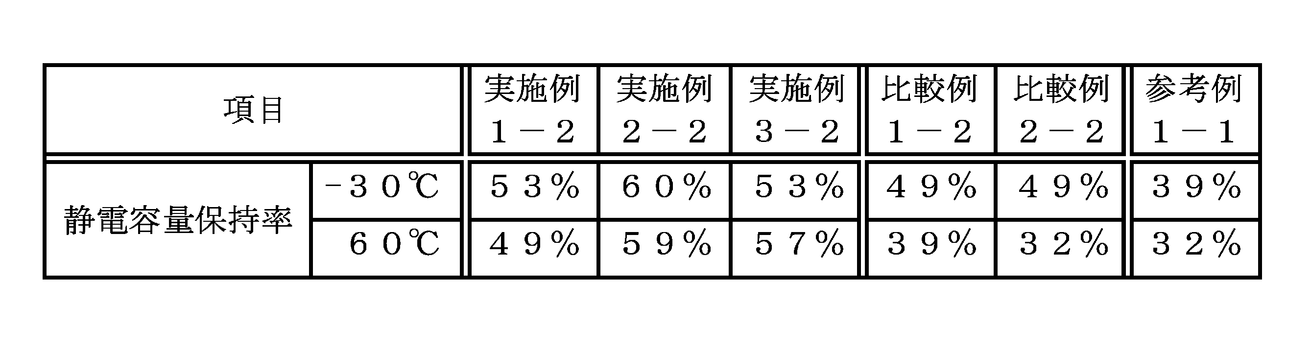
一般的に、放電電流を大きくすると静電容量は小さくなる。-30℃で充放電試験を行った場合において、1mA放電する場合の静電容量に対する50mA放電する場合の静電容量の割合を静電容量保持率として評価した場合、静電容量保持率の値が高いほど、大きな電流を流すことができる。大きな電流が流せることは、すなわち、出力が高いこととなる。
一方で、60℃で2.8Vの印加を1000時間続けて劣化試験を実施し、劣化試験の前後での静電容量を、20℃で100mA放電するという同じ放電電流で比較した場合、静電容量保持率が高いほど耐久性が良いこととなる。 Generally, the capacitance decreases as the discharge current increases. When a charge / discharge test is performed at −30 ° C., the value of the capacitance retention rate when the capacitance retention rate at 50 mA discharge to the capacitance at 1 mA discharge is evaluated as the capacitance retention rate. The higher the value is, the larger current can flow. The fact that a large current can flow means that the output is high.
On the other hand, when a deterioration test is performed by continuously applying 2.8 V at 60 ° C. for 1000 hours, and the capacitance before and after the deterioration test is compared with the same discharge current of 100 mA discharge at 20 ° C., The higher the capacity retention rate, the better the durability.
-30℃で充放電試験を行った場合において、実施例1-2~実施例3-2のラミネートセルは、比較例1-2、比較例2-2および参考例1-1と比べて高い静電容量保持率を示した。すなわち、実施例のラミネートセルは、比較例および参考例のラミネートセルよりも高い出力を出すことができた。
When the charge / discharge test was performed at −30 ° C., the laminate cells of Example 1-2 to Example 3-2 were higher than those of Comparative Example 1-2, Comparative Example 2-2, and Reference Example 1-1. The capacitance retention was shown. That is, the laminate cell of the example was able to output higher than the laminate cell of the comparative example and the reference example.
また、60℃で2.8Vの印加を1000時間続けて劣化試験を実施した場合において、実施例1-2~実施例3-2のラミネートセルは、比較例1-2、比較例2-2および参考例1-1と比べて高い静電容量保持率を示した。すなわち、実施例のラミネートセルは、比較例および参考例のラミネートセルよりも高い耐久性を示すことができた。
In addition, when the deterioration test was carried out by continuously applying 2.8 V at 60 ° C. for 1000 hours, the laminated cells of Examples 1-2 to 3-2 were Comparative Example 1-2 and Comparative Example 2-2. In addition, the capacitance retention was higher than that of Reference Example 1-1. That is, the laminate cell of the example could exhibit higher durability than the laminate cell of the comparative example and the reference example.
以上の結果より、本発明の活性炭を用いれば、電気二重層キャパシタの出力や耐久性を向上させることが、可能となることがわかった。
From the above results, it was found that using the activated carbon of the present invention makes it possible to improve the output and durability of the electric double layer capacitor.
本発明によれば、高い静電容量を維持しつつ、出力や耐久性に優れた電気二重層キャパシタやリチウムイオンキャパシタを提供することができるため、産業上有用である。
According to the present invention, since an electric double layer capacitor and a lithium ion capacitor excellent in output and durability can be provided while maintaining a high capacitance, it is industrially useful.
Claims (3)
- BET法による比表面積が1500m2/g~2500m2/gであり、
平均粒子径(D50)が0.5μm~5μmであり、
広角X線回析装置を用いて測定したd002に由来するなだらかなピークが観測でき、
表面官能基が0.5meq/g以下である活性炭。 The specific surface area according to the BET method is 1500 m 2 / g to 2500 m 2 / g,
The average particle diameter (D 50 ) is 0.5 μm to 5 μm,
A gentle peak derived from d002 measured using a wide-angle X-ray diffraction apparatus can be observed,
Activated carbon having a surface functional group of 0.5 meq / g or less. - ソフトカーボンを炭化する炭化工程と、
炭化工程後、平均粒子径(D50)が0.5μm~10μmのソフトカーボンの炭化物をアルカリ賦活剤と混合し、賦活処理する賦活処理工程と、
前記賦活処理工程により得られた賦活物を洗浄する洗浄工程と、
前記洗浄工程後の賦活物を湿式粉砕する湿式粉砕工程と、
前記湿式粉砕工程後の賦活物を乾式粉砕して、当該賦活物の平均粒子径(D50)を0.5μm~5μmとする乾式粉砕工程と、
前記乾式粉砕工程後の賦活物を、不活性ガスに10体積%以下の水素を添加した雰囲気下で、または減圧下において、400℃~700℃の温度で熱処理する熱処理工程を少なくとも含む活性炭の製造方法。 A carbonization process for carbonizing soft carbon;
After the carbonization step, an activation treatment step in which a soft carbon carbide having an average particle size (D 50 ) of 0.5 μm to 10 μm is mixed with an alkali activator and activated,
A washing step for washing the activation product obtained by the activation treatment step;
A wet pulverization step of wet pulverizing the activation product after the washing step;
A dry pulverization step in which the activated product after the wet pulverization step is dry pulverized to have an average particle size (D 50 ) of the activated product of 0.5 μm to 5 μm;
Production of activated carbon including at least a heat treatment step in which the activated product after the dry pulverization step is heat-treated at a temperature of 400 ° C. to 700 ° C. in an atmosphere in which 10% by volume or less of hydrogen is added to an inert gas or under reduced pressure. Method. - 平均粒子径(D50)が5μm~10μm、窒素ガス吸着法による比表面積が1500m2/g~2500m2/g、平均細孔直径が1.7nm~3.0nm、全細孔容積が0.5ml/g~2ml/g、およびアルカリ金属量が1000質量ppm以下である活性炭を乾式粉砕して、平均粒子径(D50)を0.5μm~5μmとする乾式粉砕工程と、
前記乾式粉砕工程後の活性炭を、不活性雰囲気下において、または減圧下において、400℃~700℃の温度で熱処理する熱処理工程を少なくとも含む活性炭の処理方法。 The average particle diameter (D 50 ) is 5 μm to 10 μm, the specific surface area by nitrogen gas adsorption method is 1500 m 2 / g to 2500 m 2 / g, the average pore diameter is 1.7 nm to 3.0 nm, and the total pore volume is 0.1. A dry pulverization step of dry pulverizing activated carbon having an alkali metal content of 1000 mass ppm or less to 5 ml / g to 2 ml / g, and an average particle size (D 50 ) of 0.5 μm to 5 μm;
A method of treating activated carbon comprising at least a heat treatment step of heat treating the activated carbon after the dry pulverization step at a temperature of 400 ° C. to 700 ° C. in an inert atmosphere or under reduced pressure.
Applications Claiming Priority (2)
| Application Number | Priority Date | Filing Date | Title |
|---|---|---|---|
| JP2014-066914 | 2014-03-27 | ||
| JP2014066914 | 2014-03-27 |
Publications (1)
| Publication Number | Publication Date |
|---|---|
| WO2015146459A1 true WO2015146459A1 (en) | 2015-10-01 |
Family
ID=54194990
Family Applications (1)
| Application Number | Title | Priority Date | Filing Date |
|---|---|---|---|
| PCT/JP2015/055656 WO2015146459A1 (en) | 2014-03-27 | 2015-02-26 | Activated carbon, method for producing activated carbon and method for treating activated carbon |
Country Status (1)
| Country | Link |
|---|---|
| WO (1) | WO2015146459A1 (en) |
Cited By (3)
| Publication number | Priority date | Publication date | Assignee | Title |
|---|---|---|---|---|
| EP3544038A4 (en) * | 2016-11-15 | 2020-07-08 | Kuraray Co., Ltd. | Carbonaceous material for electric double layer capacitors and method for producing same |
| KR20210032319A (en) * | 2018-07-20 | 2021-03-24 | 주식회사 쿠라레 | Carbonaceous materials, manufacturing methods thereof, electrode active materials for electrochemical devices, electrodes for electrochemical devices, and electrochemical devices |
| CN112551503A (en) * | 2019-09-25 | 2021-03-26 | 宁波杉杉新材料科技有限公司 | Modified soft carbon negative electrode material, lithium ion battery, negative electrode material and preparation method of negative electrode material |
Citations (11)
| Publication number | Priority date | Publication date | Assignee | Title |
|---|---|---|---|---|
| JPS60189162A (en) * | 1984-03-07 | 1985-09-26 | Matsushita Electric Ind Co Ltd | Manufacture of polarization electrode |
| JP2001284188A (en) * | 2000-04-03 | 2001-10-12 | Asahi Glass Co Ltd | Manufacturing method of carbon material for electric double-layer capacitor electrode, and manufacturing method of electric double-layer capacitor using the carbon material |
| JP2002025867A (en) * | 2000-07-04 | 2002-01-25 | Jeol Ltd | Electric double-layer capacitor and carbon material for the electric double-layer capacitor |
| JP2004149363A (en) * | 2002-10-31 | 2004-05-27 | Honda Motor Co Ltd | Method of manufacturing active carbon |
| JP2008007387A (en) * | 2006-06-30 | 2008-01-17 | Kansai Coke & Chem Co Ltd | Method and apparatus for highly purifying activated carbon |
| JP2008181949A (en) * | 2007-01-23 | 2008-08-07 | Hitachi Chem Co Ltd | Electrode material for electric double-layer capacitor and the electric double-layer capacitor |
| JP2009013012A (en) * | 2007-07-04 | 2009-01-22 | Nippon Oil Corp | Method of producing active carbon for electric double-layer capacitor electrode |
| JP2010070393A (en) * | 2008-09-16 | 2010-04-02 | Nippon Oil Corp | Carbon material for electric double layer capacitor and method for producing the same |
| WO2010044447A1 (en) * | 2008-10-15 | 2010-04-22 | 株式会社 キャタラー | Carbon material, and storage element |
| JP2011011935A (en) * | 2009-06-30 | 2011-01-20 | Kansai Coke & Chem Co Ltd | Manufacturing method of activated carbon, and electric double-layer capacitor using activated carbon obtained by the manufacturing method |
| WO2012074054A1 (en) * | 2010-12-03 | 2012-06-07 | 南開工業株式会社 | Active carbon powder and process for production thereof, and electric double layer capacitor |
-
2015
- 2015-02-26 WO PCT/JP2015/055656 patent/WO2015146459A1/en active Application Filing
Patent Citations (11)
| Publication number | Priority date | Publication date | Assignee | Title |
|---|---|---|---|---|
| JPS60189162A (en) * | 1984-03-07 | 1985-09-26 | Matsushita Electric Ind Co Ltd | Manufacture of polarization electrode |
| JP2001284188A (en) * | 2000-04-03 | 2001-10-12 | Asahi Glass Co Ltd | Manufacturing method of carbon material for electric double-layer capacitor electrode, and manufacturing method of electric double-layer capacitor using the carbon material |
| JP2002025867A (en) * | 2000-07-04 | 2002-01-25 | Jeol Ltd | Electric double-layer capacitor and carbon material for the electric double-layer capacitor |
| JP2004149363A (en) * | 2002-10-31 | 2004-05-27 | Honda Motor Co Ltd | Method of manufacturing active carbon |
| JP2008007387A (en) * | 2006-06-30 | 2008-01-17 | Kansai Coke & Chem Co Ltd | Method and apparatus for highly purifying activated carbon |
| JP2008181949A (en) * | 2007-01-23 | 2008-08-07 | Hitachi Chem Co Ltd | Electrode material for electric double-layer capacitor and the electric double-layer capacitor |
| JP2009013012A (en) * | 2007-07-04 | 2009-01-22 | Nippon Oil Corp | Method of producing active carbon for electric double-layer capacitor electrode |
| JP2010070393A (en) * | 2008-09-16 | 2010-04-02 | Nippon Oil Corp | Carbon material for electric double layer capacitor and method for producing the same |
| WO2010044447A1 (en) * | 2008-10-15 | 2010-04-22 | 株式会社 キャタラー | Carbon material, and storage element |
| JP2011011935A (en) * | 2009-06-30 | 2011-01-20 | Kansai Coke & Chem Co Ltd | Manufacturing method of activated carbon, and electric double-layer capacitor using activated carbon obtained by the manufacturing method |
| WO2012074054A1 (en) * | 2010-12-03 | 2012-06-07 | 南開工業株式会社 | Active carbon powder and process for production thereof, and electric double layer capacitor |
Cited By (6)
| Publication number | Priority date | Publication date | Assignee | Title |
|---|---|---|---|---|
| EP3544038A4 (en) * | 2016-11-15 | 2020-07-08 | Kuraray Co., Ltd. | Carbonaceous material for electric double layer capacitors and method for producing same |
| US10879014B2 (en) | 2016-11-15 | 2020-12-29 | Kuraray Co., Ltd. | Carbonaceous material for electric double layer capacitors and method for producing same |
| US11823837B2 (en) | 2016-11-15 | 2023-11-21 | Kuraray Co., Ltd. | Carbonaceous material for electric double layer capacitors and method for producing same |
| KR20210032319A (en) * | 2018-07-20 | 2021-03-24 | 주식회사 쿠라레 | Carbonaceous materials, manufacturing methods thereof, electrode active materials for electrochemical devices, electrodes for electrochemical devices, and electrochemical devices |
| KR102639869B1 (en) | 2018-07-20 | 2024-02-22 | 주식회사 쿠라레 | Carbonaceous material, manufacturing method thereof, electrode active material for electrochemical device, electrode for electrochemical device, and electrochemical device |
| CN112551503A (en) * | 2019-09-25 | 2021-03-26 | 宁波杉杉新材料科技有限公司 | Modified soft carbon negative electrode material, lithium ion battery, negative electrode material and preparation method of negative electrode material |
Similar Documents
| Publication | Publication Date | Title |
|---|---|---|
| KR101470050B1 (en) | Process for producing activated carbon for electric double layer capacitor electrode | |
| JP5473282B2 (en) | Carbon material for electric double layer capacitor and manufacturing method thereof | |
| JP5344972B2 (en) | Carbon material for electric double layer capacitor electrode and manufacturing method thereof | |
| JP6380993B2 (en) | Activated carbon for electric double layer capacitor electrode and manufacturing method thereof | |
| KR101553716B1 (en) | Active carbon for an electric double layer capacitor electrode and process for manufacturing the same | |
| US8858654B2 (en) | Activated carbon for electric double layer capacitor electrode and method for producing the activated carbon | |
| WO2011081086A1 (en) | Activated carbon for electric double-layer capacitor electrode and method for producing the same | |
| JP4092344B2 (en) | Raw material composition of carbon material for electric double layer capacitor electrode | |
| JP5242090B2 (en) | Method for producing activated carbon for electric double layer capacitor electrode | |
| WO2015146459A1 (en) | Activated carbon, method for producing activated carbon and method for treating activated carbon | |
| JPWO2007037523A1 (en) | Carbon material for electric double layer capacitor and electric double layer capacitor | |
| JP2017108022A (en) | Conductive auxiliary material, electrode and power storage device | |
| JP5242216B2 (en) | Carbon material for electric double layer capacitor electrode and manufacturing method thereof | |
| JP2005142439A (en) | Manufacturing method of activated carbon for electric double layer capacitor electrode and its carbon raw material | |
| KR102086589B1 (en) | Electrode materials, electrochemical device comprising the same and method for manufacturing the same | |
| JP2008010559A (en) | Activated carbon for electric double-layer capacitor electrode |
Legal Events
| Date | Code | Title | Description |
|---|---|---|---|
| 121 | Ep: the epo has been informed by wipo that ep was designated in this application |
Ref document number: 15770062 Country of ref document: EP Kind code of ref document: A1 |
|
| NENP | Non-entry into the national phase |
Ref country code: DE |
|
| 32PN | Ep: public notification in the ep bulletin as address of the adressee cannot be established |
Free format text: NOTING OF LOSS OF RIGHTS PURSUANT TO RULE 112(1) EPC ( EPO FORM 1205A DATED 20-01-2017 ) |
|
| NENP | Non-entry into the national phase |
Ref country code: JP |
|
| 122 | Ep: pct application non-entry in european phase |
Ref document number: 15770062 Country of ref document: EP Kind code of ref document: A1 |