WO2015146359A1 - 表示装置 - Google Patents
表示装置 Download PDFInfo
- Publication number
- WO2015146359A1 WO2015146359A1 PCT/JP2015/054095 JP2015054095W WO2015146359A1 WO 2015146359 A1 WO2015146359 A1 WO 2015146359A1 JP 2015054095 W JP2015054095 W JP 2015054095W WO 2015146359 A1 WO2015146359 A1 WO 2015146359A1
- Authority
- WO
- WIPO (PCT)
- Prior art keywords
- display device
- virtual image
- distance
- observation frame
- display
- Prior art date
Links
Images


Classifications
-
- G—PHYSICS
- G02—OPTICS
- G02B—OPTICAL ELEMENTS, SYSTEMS OR APPARATUS
- G02B30/00—Optical systems or apparatus for producing three-dimensional [3D] effects, e.g. stereoscopic images
- G02B30/20—Optical systems or apparatus for producing three-dimensional [3D] effects, e.g. stereoscopic images by providing first and second parallax images to an observer's left and right eyes
- G02B30/26—Optical systems or apparatus for producing three-dimensional [3D] effects, e.g. stereoscopic images by providing first and second parallax images to an observer's left and right eyes of the autostereoscopic type
Definitions
- the present invention relates to a display device.
- Examples of display devices that display images and characters include liquid crystal displays and plasma displays. These display devices can not adjust the diopter. With the progress of the aging society, elderly people with presbyopia (presbyopia) are increasing, and display devices capable of adjusting the diopter, in particular thin flat panel displays (hereinafter referred to as “FPD” as appropriate) are desired. There is.
- FPD thin flat panel displays
- FPDs are used as live view monitors in digital single-lens reflex cameras.
- Patent Document 1 discloses a flat panel display type display device in which a microlens array is attached in front of a conventional FPD device and a virtual image can be observed. Because it is a virtual image displayed in the distance, even people with presbyopia can observe the display without wearing glasses.
- Patent Document 2 discloses a head-up display (HUD) for a car.
- An apparatus is disclosed that displays a virtual image about 250 mm beyond the transflective portion.
- Patent Document 2 mentions the size of the semi-transmissive reflective portion necessary for binocular vision. Here, it is only disclosed that it is preferable that the semi-transmissive reflective portion corresponding to the virtual image and the observation frame be as close as possible.
- the present invention has been made in view of the above, and it is an object of the present invention to provide a display device capable of clarifying conditions of a display device capable of binocular vision of a virtual image and observing display of a virtual image by binocular vision. I assume.
- the display device of the present invention is An image display unit for displaying an image; And a virtual image forming unit that forms a virtual image of the image; It is characterized in that the entire virtual image is observed in one observation frame from two different points.
- another display device of the present invention is A spatial light phase modulation element that forms a virtual image of an image, which has the functions of an image display unit and a virtual image formation unit; In a display in which the whole of the virtual image is observed from two different points, at least one side of L is a conditional expression (1) or a conditional expression (2 It is characterized by satisfying.
- a focused display can be viewed with both eyes. That is, the display device according to the present invention allows a viewer to view a virtual image in the distance, so that even a person who can not focus on the near point where the display device exists can see the display in focus with both eyes. Have the effect of Furthermore, the display device of the present invention can reduce the burden on both eyes of a presbyopia observer, for example, and can perform observation without adding reading glasses or other optical parts. Furthermore, even a far-sighted person can view a focused image (not only pictures but also all displayed information) with both eyes without using glasses. In addition, with binocular vision, the display can be viewed with a natural sense.
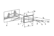
- FIG. 1 is a view for explaining the basic configuration and operation of a display device 3a according to a first embodiment of the present invention.
- the display device 3 a includes an image display unit 1 and a virtual image forming unit 2.
- the image display unit 1 and the virtual image forming unit 2 are integrally configured as a display device 3a.
- Two different points 4 and 5 which are observation points respectively correspond to the left and right eyes of the observer (not shown).
- observation is performed such that a reference axis AX passing through the center of the display surface of the display device 3a and perpendicular to the display surface overlaps the centers of the observation points of the two points 4 and 5.
- the observer can observe the virtual image 6 in the observation frame 7 when observing the display device 3a.
- the observation frame 7 is to limit the size of the light flux emitted from the virtual image forming unit 2 and entering the eye on the exit surface of the display 3 a.
- a frame may physically exist, or the field of view may be limited by the size of the optical system of the exit surface.
- FIG. 1 shows binocular vision of virtual image display in the present embodiment.
- the entire virtual image 6 is observed from the left and right eyes (2 points) 4 and 5, respectively. Conventionally, even when the observer intends to view with binocular vision, it may become monocular vision before the observer himself is conscious.
- FIG. 3 shows such a situation. This is the case when reading characters such as a newspaper through the loupe LP.
- the loupe LP functions equivalent to the virtual image display device.
- the loupe LP enlarges the characters described in a newspaper or the like as a virtual image 6.
- the regions A, B and C of all of the virtual image 6 can be recognized.
- the region B is viewed binocularly.
- binocular vision is partially, for example, a row relative to the region B
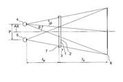
- FIG. 1 The appearance of FIG. 1 viewed from above is shown in FIG.
- L be the size of the observation frame 7.
- the distance between the observation frame 7 and the intermediate point of the two points 4 and 5 ie, the distance between the intermediate point of both eyes (observation distance) is f e
- the distance between the observation frame 7 and the virtual image 6 is f v
- the half angle of view of the virtual image is ⁇
- the diameter of the luminous flux passing through the observation frame 7 is D.
- the distance between two different points is P.
- condition for binocular vision is to satisfy the following conditional expression (1) or conditional expression (2).
- the display device is at a short distance. Therefore, as for observation distance fe , 1 m or less is desirable.
- the distance f v to the virtual image is preferably 1 m or more.
- the average distance between the eyes (eye width) is about 65 mm
- the value of P is preferably 60 to 70 mm.
- the image display unit 1 and the virtual image forming unit 2 integrally constitute a display 3a. It has a thin shape like an existing flat panel display. Of course, as in the case of the conventional flat panel display, there is a configuration in which asperities are present on the back by a substrate that performs various digital processing and a unit that communicates various information with the outside. Usually, it is often 100 mm or less.
- a thin display device capable of always observing a virtual image display with binocular vision. For example, even a presbyopic person can always observe a virtual image display with binocular vision without wearing glasses.
- FIG. 4 is a view for explaining the basic configuration and operation of the display device of the second embodiment.
- the display device 3 b is configured of a lens array 8 and a display device 9.
- the display 11 is displayed on the display device 9 at a position corresponding to each lens 10 of the lens array 8 and in a display area surrounded by a broken line.
- the display 11 performs the same display corresponding to the other lenses.
- the display contents are display contents that the observer finally observes.
- a broken line indicating one display area in the display device 9 is a description for helping understanding and does not actually exist.
- the shape of the lens 10 is the same as the range of the display 11.
- the lens 13 indicates the lenses of the left and right eyes of the observer.
- the image 14 is an image reflected on the retina of each eye.
- the lens 13 of the eye is in focus at infinity as a person with presbyopia or hyperopia. For this reason, the parallel light of arrow 12 is collected on the retina. That is, the observer can observe an in-focus image.
- binocular vision becomes possible as shown in FIG.
- FIG. 5 shows a configuration in which the display device 3b of this embodiment is viewed from the lateral (side) direction.
- Each display 11 is projected at infinity by each corresponding lens 10.
- each display 11 since each display 11 is exactly the same, the luminous flux emitted from each lens forms one large parallel luminous flux. Only four lenses are shown in the figure. However, in practice, a very large number of lenses are arranged in the vertical direction and in the front and back of the sheet.
- FIG. 5 shows a state in which a light flux 15 by four lenses of them is incident on the lens 13 of the observer's eye.
- the light flux 15 is parallel light and forms a virtual image at infinity.
- the lens array 8 is a virtual image forming unit 2.
- the lens 13 of the observer's eye which is only in focus at infinity, can be focused and the in-focus image 14 is projected onto the retina.
- the lens array 8 is the pupil of the display device.
- an observer is known to look through an eyepiece. Since the pupil of the optical system is formed only in the vicinity of the eyepiece lens, in order to observe an image, it is necessary to align the lens of the eye with the position of the eye point.
- the entire lens array 8 is the pupil of the optical system, and the operation of looking into it like a microscope is not necessary. Also, the display can be viewed from a position away from the display device. In the case of binocular vision, the size of the lens array 8 corresponds to the observation frame 7.
- the size of the exit light beam of the lens array 8 that is the virtual image forming unit 2 on the exit surface corresponds to the observation frame 7.
- the observation frame 7 may be the size of the optical system itself without being physically provided.
- the focal length of the lenses can be shortened.
- the thickness of the display device including the display device 9 as the image display unit and the lens array 8 as the virtual image forming unit As a result, it is possible to provide FPD which is a thin display device capable of displaying a virtual image.
- the display device of the present application can be configured. However, since the display device becomes thicker (larger), it is unsuitable for portable electronic devices. Even in such a case, it can be used for a vehicle-mounted HUD (head-up display).
- the virtual image can be displayed at a finite distance by displaying the display 11 little by little so that the light flux 15 is diverged.
- the size of the observation frame 7 is the effective aperture of the lens array 8. It is desirable to satisfy the conditional expression equivalent to that of the first embodiment. The case where it uses for the tablet for learning, a personal computer, etc. is assumed.
- the size of the screen is 355 mm ⁇ 200 mm (16 type). When viewing the screen 400 mm apart, the half angle of view ⁇ is ⁇ 24 degrees ⁇ ⁇ 14 degrees.
- the size of the minimum observation frame 7 necessary binocular vision, from condition (2), a 376mm ⁇ 239mm. It is desirable that at least one side of the observation frame 7 has a size equal to or larger than this value. That is, it is only necessary that the direction (horizontal direction) for binocular vision satisfies this value. In the case of horizontal use, the horizontal direction needs to be 376 mm or more, and in the case of the vertical use, the horizontal direction needs to be 239 mm or more.
- the observation distance f e was 350 mm and the eye width was 65 mm.
- the display device 3b of the present embodiment is used for a large television.
- the size of the screen is 2221 mm ⁇ 1250 mm (100 type).
- the half angle of view ⁇ is ⁇ 29 degrees ⁇ ⁇ 17 degrees.
- the distance f e 2000 mm
- the distance f v to the virtual image of the display device according to the present embodiment is sufficient at 1 m.
- the size of the minimum observation frame 7 required for binocular vision is 2267 mm ⁇ 1275 mm. It is desirable that at least one side of the observation frame 7 has a size equal to or larger than this value. That is, it is only necessary that the direction (horizontal direction) for binocular vision satisfies this value. In the case of horizontal use, the horizontal direction needs to be 2267 mm or more, and in the case of vertical use, the horizontal direction needs to be 1275 mm or more. Here, the eye width was 65 mm.
- the viewing distance is already 2 m, which is an area where the virtual image display is not necessarily required.
- the screen may be viewed near the wall, for example, at an observation distance f e of about 1 m.
- the virtual image display of the display device 3b of the present embodiment is effective even for a large television (wallpaper television).
- the observation distance f e is preferably designed to be 1 m or less. In that case, the distance f v between the observation frame 7 of the display device 3 b and the virtual image is desirably 1 m or more.
- this embodiment it is possible to realize a thin tablet, a personal computer, a television, or the like equipped with a display device capable of always observing a display with binocular vision. In particular, even for people with presbyopia, it is not necessary to put on and take off the glasses without putting on the glasses.
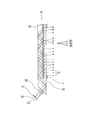
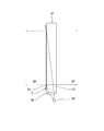
- FIG. 6 shows a cross-sectional configuration of a display device 3c of the third embodiment. It is an example of a thin display that displays a virtual image in which the observation frame 7 is enlarged using the light guide plate 16.
- the small display device 17 of several mm square is enlarged by the small lens 18 to see an image displayed on the display device 17.
- the aperture of the lens 18 is small and it is necessary to bring the eye into close contact with the lens 18 and look around. For this reason, as with normal FPD, the observer can not look away.
- the light beam emitted from the lens 18 is made to enter the light guide plate 16.
- the light incident on the light guide plate 16 is totally reflected and propagated through the light guide plate 16.
- the hologram 19 diffracts a part of the light that travels by total reflection in the light guide plate 16 and emits the light outside the light guide plate 16.
- the display device 17 is provided at the focal position of the lens 18. As a result, the luminous flux emitted from the center 20 of the displayed image of the display device 17 becomes parallel luminous flux and is incident on the light guide plate 16. As a result, the inside of the light guide plate 16 is totally reflected and transmitted, and a part thereof is emitted from the light guide plate 16 as the parallel light beam 21 by the hologram 19.
- the light beam reflected by the hologram 19 is subsequently totally reflected in the light guide plate 16 and transmitted, and a part of the light beam is emitted from the light guide plate 16 as a parallel light beam by the hologram 19. That is, it is emitted in the direction of the arrow 22 as a parallel luminous flux whose diameter is increased from almost the entire area of the surface of the light guide plate 16.
- the light beam emitted from the end 23 of the image displayed on the display device 17 becomes a parallel light beam and is incident on the light guide plate 16. Then, the light is totally reflected in the light guide plate 16 and transmitted, and a part of the light is emitted as a parallel light beam by the hologram 19.
- the direction of injection is indicated by arrow 24.
- the luminous flux from the opposite end of the display device 17 is likewise emitted from the light guiding plate 16 as a parallel luminous flux in the direction of the arrow 25. That is, the small pupil of the lens 18 is combined from the surface of the light guide plate 16, and a parallel light flux having a large diameter (light flux width) is emitted. Thereby, the observation frame 7 can be enlarged. As a result, binocular vision of a virtual image by an observer becomes possible.
- the observer can view the image displayed on the display device 17 at a position away from the light guide plate 16. Because of the parallel luminous flux, for example, even a person with a presbyopia can observe the displayed image well.
- FIG. 6 shows a light guide in one direction, which is an elongated display 3c. If two light guide plates are used, a normal aspect ratio display device can be made. The situation is shown in FIG.
- the light guide plate 16 guides light in the direction of the arrow 26 and makes light enter the light guide plate 27.
- the light guide plate 27 guides light in the direction of the arrow 28. This makes it possible to combine the small pupil of the lens 18 into a large pupil.
- the display 3 d can be made as thin as a light guide plate.
- the image display unit is a display device 17, and the virtual image forming unit is a lens 18.
- the size of the observation frame 7 is an effective opening of the light guide plate 27, and it is desirable that the condition equal to that of the first embodiment be satisfied.
- the size of the screen is 58 mm ⁇ 104 mm (4.7 type).
- the half angle of view ⁇ is ⁇ 6.6 degrees ⁇ ⁇ 11.7 degrees.
- the magnitude of the minimum observed frame 7 necessary binocular vision, from the condition (1) a 95 mm ⁇ 123 mm. It is desirable that at least one side of the observation frame 7 has a size equal to or larger than this value.
- the direction (horizontal direction) for binocular vision satisfies this value.
- the horizontal direction needs 95 mm or more, and in the case of using the horizontal direction, the horizontal direction needs 123 mm or more.
- the observation distance was 150 mm and the eye width was 65 mm.
- the display devices 3c and 3d capable of always observing a display with binocular vision
- a portable electronic device such as a mobile phone and a smartphone.
- even a presbyopic person can easily observe the image without wearing glasses.
- FIG. 8 shows a cross-sectional configuration of a display device 3e of the fourth embodiment. Similar to the third embodiment, it is a thin display that displays a virtual image for enlarging the observation frame using the light guide plate 16. The present embodiment is different from the third embodiment in that the display of an image is performed in a scanning manner.
- a collimated light beam is formed using the semiconductor laser 30 and the lens 31.
- a collimated beam is made incident on the rotating mirror 32.
- the parallel luminous flux reflected by the rotating mirror 32 enters the light guide plate 16 and is totally reflected and transmitted in the light guide plate 16.
- the hologram 19 diffracts a part of the light transmitted by totally reflecting in the light guide plate 16 and emits the light outside the light guide plate 16.
- the light beam reflected by the hologram 19 is subsequently totally reflected in the light guide plate 16 and transmitted, and a part of the light beam is emitted from the light guide plate 16 as a parallel light beam by the hologram 19.
- the parallel light flux is totally reflected and transmitted in the light guide plate 16, and a part of the parallel light flux is emitted as a parallel light flux by the hologram 19.
- the direction of injection is the direction indicated by arrow 24.
- the parallel light flux from the rotating mirror 32 rotated to the opposite side is totally reflected by the light guide plate 16 and transmitted, and a part thereof is diffracted by the hologram 19 and emitted from the light guide plate 16 as a parallel light flux in the direction of the arrow 25.
- the small aperture (pupil) of the rotating mirror 32 is combined from the surface of the light guide plate 16, and a large parallel beam is emitted.
- An observer can view an image displayed by the light source (semiconductor laser) 30 and the rotating mirror 32 rotating at a position away from the light guide plate 16.
- FIG. 8 shows a light guide in one direction, which is a display device 3e having an elongated shape. Furthermore, if two light guide plates are used, a normal aspect ratio display device can be made. This configuration is the same as that of FIG. 7 shown in the third embodiment. By making the observation frame 7 sufficiently large, binocular vision becomes possible.
- the image display unit is a light source (semiconductor laser) 30 and a rotating mirror 32, and is also a virtual image forming unit at the same time.
- a light source semiconductor laser
- FIG. 8 it goes without saying that lasers of respective wavelengths of red, green and blue can be provided to display a color image.
- the size of the observation frame 7 is the effective opening of the light guide plate 27. It is desirable that the size of the observation frame 7 satisfy the condition equivalent to that of the first embodiment.
- the size of the screen is 58 mm ⁇ 104 mm (4.7 type).
- the half angle of view ⁇ is ⁇ 6.6 degrees ⁇ ⁇ 11.7 degrees.
- the size of the minimum observation frame 7 necessary for binocular vision is 100 mm ⁇ 127 mm according to conditional expression (1). It is desirable that at least one side of the observation frame 7 has a size equal to or larger than this value. That is, it is only necessary that the direction (horizontal direction) for binocular vision satisfies this value.
- the horizontal direction When using in the vertical direction, the horizontal direction needs 100 mm or more, and in the case of using the horizontal direction, the horizontal direction needs 127 mm or more.
- the observation distance was 150 mm and the eye width was 65 mm.
- FIG. 9 shows a cross-sectional configuration of a display 3f of the fifth embodiment.
- Holography is known that reproduces a wavefront from a flat plate and displays a stereoscopic image in the flat plate.
- a flat plate is called a hologram.
- the interference fringes recorded on the hologram are very fine, and conventionally special photographic plates have been used.
- pixels of liquid crystal display devices and the like have become extremely fine and the number of pixels has also increased.
- a spatial light phase modulation element has been put to practical use, which two-dimensionally modulates the wavefront of light instead of displaying normal light intensity.
- the display device 3f is a device that displays a hologram on the spatial light phase modulation element 34, emits reproduction light to reproduce a virtual image, and displays the virtual image.
- the spatial light phase modulation element is illuminated by the light source 35 and the lens 36, a virtual image is reproduced.
- the spatial light phase modulation element 34 When the spatial light phase modulation element 34 is of a reflection type, a light flux for displaying a virtual image is emitted in the direction of the arrow 37. The observer can view the virtual image seen in the direction of the arrow 38 by looking at the display 3 f from the direction of the arrow 37.
- the spatial light phase modulation element 34 When the spatial light phase modulation element 34 is of a transmission type, a light flux for displaying a virtual image is emitted in the direction of the arrow 38, and the observer looks at the display 3f from the direction of the arrow 38 and in the direction of the arrow 37 The visible virtual image can be observed.
- the light source 35 is a light source of three primary colors of red, green and blue, and can reproduce a color image by time division. When the observation frame 7 is sufficiently large, binocular vision becomes possible.
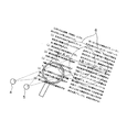
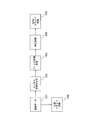
- FIG. 10 is a block diagram showing an example of a method of generating hologram information to be displayed on the spatial light phase modulator.
- the exit wavefront of the imaging optical system can be obtained by Fourier transforming (103) the image data 101 to be displayed.
- the spatial frequency distribution determined by the Fourier transform (103) produces a spatial phase distribution as well as a spatial intensity distribution. As it is, it is not possible to form a phase hologram with high diffraction efficiency. If random phase information (102) is superimposed on video data in advance, values of spatial intensity after Fourier transform can be averaged over the entire spatial frequency surface, and the intensities can be equalized. That is, it can be phase information.
- correction processing based on the arrangement of the optical system is performed (104).
- the wavefront from the coherent light source 35 of FIG. 9 is a spherical wave.
- the hologram is calculated with the information of the spherical wave so that the correct display beam is formed when the spherical wave reproduces the hologram.
- the hologram information is input to the spatial light phase modulation device (SPM) driver 105, and the hologram is displayed on the spatial light phase modulation device.
- SPM spatial light phase modulation device
- the diffraction efficiency of the spatial light phase modulator 34 is almost constant, and the brightness of the image of the bright scene or the image of the dark scene is almost the same. Therefore, when forming a display light beam in a holographic manner, it is necessary to control the amount of light to be incident on the spatial light phase modulation element 34 according to the total amount of light of the image.
- the total light amount data of the image data is sent to the light source driver 106 to control the brightness of the light source.
- the size of the observation frame 7 is an effective display area of the spatial light phase modulation element 34, and it is desirable that the condition equal to that of the first embodiment be satisfied.
- the case where this embodiment is used for a tablet for learning, a personal computer, etc. is assumed.
- the size of the screen is 311 mm ⁇ 175 mm (14 type). When observed at a distance of 300 mm, the half angle of view ⁇ is ⁇ 27 degrees ⁇ ⁇ 16 degrees.
- the magnitude of the minimum observed frame 7 necessary binocular vision from condition (2), a 364 mm ⁇ 231 mm. It is desirable that at least one side of the observation frame 7 has a size equal to or larger than this value. That is, it is only necessary that the direction (horizontal direction) for binocular vision satisfies this value.
- the horizontal direction in the horizontal direction, 364 mm or more, in the case of using vertically, it is necessary that the horizontal direction is 231 mm or more.
- the observation distance f e was 300 mm, and the eye width was 60 mm.
- the display devices 3b, 3c, 3d (modifications), 3e, 3f for performing the virtual image display shown in the second to fifth embodiments described above are portable electronic devices such as mobile phones, smart phones, electronic dictionaries, etc.
- the observation distance is about 150 to 300 mm in a portable terminal.
- the half angle of view is approximately 5 to 10 degrees from the size of 4 to 5 inches of a general display surface.
- conditional expression (1) of the first embodiment is obtained assuming that the observation distance fe is 150 mm and the half angle of view ⁇ is 5 degrees.
- conditional expression (3) is obtained.
- the range of the size L of the observation frame 7 satisfy the following conditional expression (5).
- the value of the eye width was set to 65 mm.
- the distance f v of the observation frame 7 and the virtual image 6 1m or more is preferable. For this reason, the range shown below is desirable. 82.7 ⁇ L ⁇ 170.8
- the size of the observation frame of the binocular vision virtual image display device used for the portable electronic device is in the range of 82.7 to 170.8 mm at least on one side.
- the display devices 3b, 3c, 3d (modifications), 3e and 3f shown in the second to fifth embodiments are used as display devices for desktop electronic devices such as personal computers (PCs) and tablet terminals. Think about using it. Actually, the observation distance is about 300 to 600 mm at a desk top terminal. In addition, the size of a general display surface is approximately 16 to 20 inches, and the half angle of view is approximately 15 to 20 degrees.
- conditional expression (1) of the first embodiment is obtained.
- the value of the eye width was set to 65 mm. Furthermore, the distance f v of the observation frame 7 and the virtual image 6 1m or more is preferable. For this reason, the range shown below is preferable. 210.8 ⁇ L ⁇ 501.8
- the size of the observation frame of the binocular vision virtual image display device used for the desk-top type electronic device is in the range of 210.8 to 501.8 mm at least on one side.
- the present invention is useful for a display device capable of observing a display of a virtual image with binocular vision.
Abstract
虚像を両眼視できる表示装置の条件を明確にし、両眼視で虚像の表示を観察することができる表示装置を提供する。 画像を表示する画像表示部1と、画像の虚像を形成する虚像形成部2と、を有し、異なる2点からそれぞれ虚像の全体が一つの観察枠の中において観察されることを特徴とする表示装置である。また、本表示装置の構成として、好ましくは、画像表示部1と虚像形成部2とがフラットパネルとして構成されていることが望ましい。
Description
本発明は、表示装置に関するものである。
映像や文字を表示する表示装置(ディスプレイ)として、液晶ディスプレイやプラズマディスプレイなどがある。これらの表示装置は、視度の調節が出来ない。高齢化社会の進展に伴って老眼(老視)の高齢者が増えており、視度調節が可能な表示装置、特に薄型のフラットパネルディスプレイ(以下、適宜「FPD」という。)が望まれている。
以下、理解を容易にするために、老眼視を例にして説明をする。携帯電話の普及やデジタルカメラの普及により、屋外でFPDによる表示を見る機会が増えている。更に本の代わりに電子ブックの利用も増加している。このように携帯電話やデジタルカメラ等のモバイル機器のFPDを見るときに、いちいち老眼鏡を掛け、外しするのは非常に煩わしい。
携帯電話は、電話として使用するよりも、メールの使用、ゲーム等の場面でFPDを見る機会が多い。また、デジタル一眼レフカメラには、ライブビューモニターとしてFPDが用いられている。
このデジタル一眼レフカメラにおいて、遠方の被写体を見つつ、ライブビューモニターを見るのに、そのたびに老眼鏡を掛けたり外したりするのは、実際的ではない。さらに、撮影モードの変更等、モニターを利用したGUI(グラフィカルユーザインターフェイス)を使用することが多い。このため、モニターを見る必要性は高い。
また、カーナビゲーションシステムのモニターを見るときは、観察者は運転中である。このため、前方からモニターを見るときに、老眼鏡を掛け外しするのは危険である。老眼鏡の掛け外しは事実上不可能である。
さらに他の場面として、パーソナルコンピュータ(PC)の液晶画面を観察する時も、そのたびに、老眼鏡を掛けるのは観察者にとって煩わしい。したがって、老眼鏡を掛け外しすることなくモニターを見ることのできる電子機器が望まれている。
例えば、特許文献1には、マイクロレンズアレイを従来のFPDデバイスの前に取り付け、虚像を観察できるフラットパネルディスプレイ型の表示装置が開示されている。遠方に表示される虚像なので老眼の人でも眼鏡をかけることなく表示を観察することができる。
また、特許文献2には、自動車用のヘッドアップディスプレイ(HUD)が開示されている。半透過反射部の先250mm程度に虚像を表示する装置が開示されている。
特許文献1に開示されている構成においては、観察者と虚像表示装置の位置によっては、虚像が表示装置の観察枠から外れて虚像の一部が観察できない。また、虚像観察時に必ずしも両眼視になっていない。その場合、観察者は不自然な画像を見ていることになる。
また、特許文献2には、両眼視に必要な半透過反射部の大きさについて言及されている。ここでは、虚像と観察枠に相当する半透過反射部ができる限り近いことが好ましいことが開示されているだけである。
本発明は、上記に鑑みてなされたものであって、虚像を両眼視できる表示装置の条件を明確にし、両眼視で虚像の表示を観察することができる表示装置を提供することを目的とする。
上述した課題を解決し、目的を達成するために、本発明の表示装置は、
画像を表示する画像表示部と、
画像の虚像を形成する虚像形成部と、を有し、
異なる2点からそれぞれ虚像の全体が一つの観察枠の中において観察されることを特徴とする。
また、本発明の別の表示装置は、
画像表示部と虚像形成部との機能を兼用する、画像の虚像を形成する空間光位相変調素子を有し、
異なる2点からそれぞれ虚像の全体が観察される表示装置において、空間光位相変調素子からの光束が射出する大きさをLとして、少なくともその一辺が、後述する条件式(1)または条件式(2)を満たすことを特徴とする。
画像を表示する画像表示部と、
画像の虚像を形成する虚像形成部と、を有し、
異なる2点からそれぞれ虚像の全体が一つの観察枠の中において観察されることを特徴とする。
また、本発明の別の表示装置は、
画像表示部と虚像形成部との機能を兼用する、画像の虚像を形成する空間光位相変調素子を有し、
異なる2点からそれぞれ虚像の全体が観察される表示装置において、空間光位相変調素子からの光束が射出する大きさをLとして、少なくともその一辺が、後述する条件式(1)または条件式(2)を満たすことを特徴とする。
本発明の表示装置によれば、焦点の合った表示を両眼で見ることが出来る。
即ち、本発明に係る表示装置は、観察者に遠方の虚像を観察させることにより、通常表示装置が存在する近点に焦点を合わせることのできない人でも焦点の合った表示を両眼で見ることができる効果がある。
さらに、本発明の表示装置は、例えば、老眼の観察者の両眼の負担を軽減し、老眼鏡その他の光学部を追加することなく観察することができる。更に、遠視の人でもメガネを用いることなく、焦点の合った画像(絵だけでなく文字など、表示される全ての情報のこと)を両眼で見ることが出来る。また、両眼視により、自然な感覚で表示を見ることができる。
即ち、本発明に係る表示装置は、観察者に遠方の虚像を観察させることにより、通常表示装置が存在する近点に焦点を合わせることのできない人でも焦点の合った表示を両眼で見ることができる効果がある。
さらに、本発明の表示装置は、例えば、老眼の観察者の両眼の負担を軽減し、老眼鏡その他の光学部を追加することなく観察することができる。更に、遠視の人でもメガネを用いることなく、焦点の合った画像(絵だけでなく文字など、表示される全ての情報のこと)を両眼で見ることが出来る。また、両眼視により、自然な感覚で表示を見ることができる。
以下に、本発明にかかる表示装置の実施形態を図面に基づいて詳細に説明する。なお、この実施形態によりこの発明が限定されるものではない。
(第1実施形態)
図1は、本発明による第1実施形態の表示装置3aの基本構成と作用を説明する図である。
表示装置3aは、画像表示部1と、虚像形成部2で構成されている。ここで、画像を表示せず虚像形成部2のみで虚像を表示することも可能である。この例は、別途後述する実施形態で示す。
図1は、本発明による第1実施形態の表示装置3aの基本構成と作用を説明する図である。
表示装置3aは、画像表示部1と、虚像形成部2で構成されている。ここで、画像を表示せず虚像形成部2のみで虚像を表示することも可能である。この例は、別途後述する実施形態で示す。
ここでは、画像表示部1と虚像形成部2を一体として表示装置3aとして構成する。観察点である異なる2点4、5は、それぞれ(不図示の)観察者の左右の眼に相当する。図1では、表示装置3aの表示面の中心を通りかつ表示面に垂直な基準軸AXと、2点4、5の観察点の中心が重なるようにして観察を行っている。観察者は、表示装置3aを観察すると、観察枠7の中に虚像6を観察できる。
観察枠7とは、虚像形成部2から射出して眼に入る光束の表示装置3aの射出面における大きさを制限するものである。実際に物理的に枠が存在していても良いし、または射出面の光学系の大きさによって視野が制限されてもよい。
図1は、本実施形態における虚像表示の両眼視を示している。左右の眼(2点)4、5それぞれから虚像6全体が観察される。従来、観察者は、両眼視で見ているつもりの場合でも、観察者自身が意識しないうちに、片眼視となる場合がある。
これは、観察距離feで両眼視が不可能な観察枠7の大きさに対して半画角φが設定されている場合に生じる。
図3は、このような状況を示している。これは、ルーペLPを通して新聞などの文字を読む場合である。ここでルーペLPは虚像表示装置と等価な作用をする。ルーペLPは新聞などに記載文字を虚像6として拡大する。
これにより、細かい文字を読むこと、近点に焦点の合わない老眼の人でも文字が読めることが可能となる。視点4から虚像を観察すると領域B及び領域Cの領域を認識する。一方、視点5から虚像を観察すると領域A及び領域Bの領域を認識する。
両眼視をすると虚像6の全ての領域A、領域B及び領域Cの領域を認識することができる。ここで、両眼視しているのは領域Bのみである。観察者は、両眼視をしているつもりでも、観察枠7に相当するルーペLPのレンズLSの大きさが不十分の場合は、両眼視は一部、例えば、領域Bに対して行われている。
観察者は、実際には多くの画像を片眼視している(領域A、領域C)。両眼視のためには、図1に示すような観察枠7の条件式を満足することが必要となる。図1を上方より見た様子を図2に示す。
観察枠7の大きさをLとする。観察枠7と異なる2点4、5の中間点との距離、すなわち、ここでは、両眼の中間点との距離(観察距離)をfe、観察枠7と虚像6との距離をfv、虚像の半画角をφ、観察枠7を通る光束径をDとする。異なる2点の距離はPである。
条件式は、図1、或いは図2より近似的に、以下のように示される。

或いは、より正確には、図1、或いは図2より、以下の条件式(2)を満足することが望ましい。

すなわち、以下の条件式(1)または条件式(2)を満足することが両眼視の条件となる。

ここで、観察枠7の少なくとも一辺が、この条件式(1)または条件式(2)を満たしていることが望ましい。
本実施形態を老眼用に用いる場合は、多くの場合、表示装置が近距離にある場合である。したがって、観察距離feは、1m以下が望ましい。
本実施形態を老眼用に用いる場合は、多くの場合、表示装置が近距離にある場合である。したがって、観察距離feは、1m以下が望ましい。
また、老眼では近距離には焦点が合わない。このため、虚像までの距離fvは、1m以上が好ましい。例えば、異なる2点を人の両眼とする場合は、両眼の距離(眼幅)の平均は、約65mmであり、Pの値は60~70mmが好ましい。
画像表示部1と虚像形成部2は、一体として表示装置3aを構成している。既存のフラットパネルディスプレイのように薄型の形状をしている。もちろん、各種デジタル処理を行う基板や各種情報を外部と通信する部などによって背面に凹凸が存在する構成があるのは、従来のフラットパネルディスプレイと同様である。通常、100mm以下である場合が多い。
以上説明したように、本実施形態により、常に両眼視で虚像表示を観察することができる薄型の表示装置を提供できる。例えば、老眼の人でも眼鏡をかけることなく、常に両眼視で虚像表示を観察することができる。
(第2実施形態)
図4は、第2実施形態の表示装置の基本構成と作用を説明する図である。表示装置3bは、レンズアレイ8と、表示デバイス9で構成されている。表示デバイス9には、レンズアレイ8の各レンズ10に対応した位置であって、破線で囲われた表示領域において表示11が行われる。
図4は、第2実施形態の表示装置の基本構成と作用を説明する図である。表示装置3bは、レンズアレイ8と、表示デバイス9で構成されている。表示デバイス9には、レンズアレイ8の各レンズ10に対応した位置であって、破線で囲われた表示領域において表示11が行われる。
表示11は、その他のレンズにも対応して同じ表示が行われる。表示内容は観察者が最終的に観察する表示内容である。なお、図中、表示デバイス9の中で一つの表示領域を示す破線は、理解を助ける為の記載で実際には存在しない。
表示11は、レンズ10によって図中矢印12のように平行光で無限遠に投影される。すなわち、無限遠に虚像ができる。また、表示デバイス9にはレンズアレイ8のレンズと同じ数だけ同じ表示が成される。レンズ10は、3×3=9個示されている。なお、レンズの個数はこれに限らない。
レンズ10の形状は、表示11の範囲と同じ形状になっている。図中、レンズ13は観察者の左右の眼のレンズを示している。像14はそれぞれの眼の網膜上に映った像である。眼のレンズ13は老眼や遠視の人のように無限遠にピントが合っている。このため、矢印12の平行光を網膜上に集光する。すなわち、観察者は、焦点の合った像を観察できる。観察枠であるレンズアレイの大きさが十分大きいと、図4のように両眼視が可能となる。
さて、上記結像作用を、図5を用いて再び詳説する。図5は簡単のため、本実施形態の表示装置3bを横(側面)方向から見た構成を示している。各表示11は、それに対応する各レンズ10によって無限遠に投影される。
このとき、各表示11は、全く同じであるから、各レンズから射出される光束は一つの大きな平行光束を作ることになる。図では、レンズは4個のみ示している。しかしながら、実際には、非常に多くのレンズが上下及び紙面の手前奥方向に配置されている。
図5は、その内の4個のレンズによる光束15が観察者の眼のレンズ13に入射している様子を示している。光束15は平行光であり、無限遠に虚像を形成している。レンズアレイ8は虚像形成部2である。
従って、無限遠の像にしか焦点の合わない観察者の眼のレンズ13でも焦点を合わせることができ、焦点の合った像14が網膜上に投影される。
ここで、レンズアレイ8が表示装置の瞳になっていると考えることができる。例えば、顕微鏡では、観察者は接眼レンズを覗くことが知られている。接眼レンズの近傍にのみ光学系の瞳が形成されるため、像を観察する為には、そのアイポイントの位置に眼のレンズを合わせる必要がある。
従って、顕微鏡を代表とする光学機器では、観察者は覗き込む動作が必要になる。但し、接眼レンズから射出される光束は、無限遠から来たのと等価な平行光に調整できるので、老眼の人でも容易に焦点の合った顕微鏡像を観察できる。
本実施形態による表示装置3bは、レンズアレイ8全体が光学系の瞳となっており、顕微鏡のように覗き込む動作が必要ない。また、表示装置から離れた位置から表示を見ることができる。なお、両眼視の場合は、このレンズアレイ8の大きさが観察枠7に相当する。
虚像形成部2であるレンズアレイ8の射出光束の射出面での大きさが観察枠7に相当する。観察枠7は物理的に設けなくても、光学系の大きさそのものでよい。
レンズアレイ8のレンズ数が多いと、レンズの焦点距離を短くできる。これにより、画像表示部である表示デバイス9と虚像形成部であるレンズアレイ8で構成される表示装置を薄型化できる。この結果、虚像を表示することができる薄型の表示装置であるFPDを提供できる。
レンズアレイ8のレンズ数が1個の場合でも本願の表示装置を構成可能である。しかしながら、表示装置が厚くなる(大型化する)ので携帯電子機器には不向きである。このような場合でも、車載用のHUD(ヘッドアップディスプレイ)には使用することができる。
なお、光束15が発散するように、表示11を少しずつずらして表示することにより有限遠に虚像を表示することができる。
観察枠7の大きさはレンズアレイ8の有効開口である。第1実施形態と同等の条件式を満たすことが望ましい。
学習用タブレットやパーソナルコンピュータなどに用いる場合を想定する。画面の大きさを355mm×200mm(16型)とする。画面を400mm離れて観察すると、半画角φは、±24度×±14度となる。
学習用タブレットやパーソナルコンピュータなどに用いる場合を想定する。画面の大きさを355mm×200mm(16型)とする。画面を400mm離れて観察すると、半画角φは、±24度×±14度となる。
本実施形態による表示装置3bの虚像までの距離fvを5mとすると、両眼視に必要な最低限の観察枠7の大きさは、条件式(2)より、376mm×239mmとなる。観察枠7の少なくとも一辺がこの値以上の大きさであることが望ましい。すなわち、両眼視をする方向(水平方向)がこの値を満たしていればよい。横長で使う場合は、水平方向が376mm以上、縦長で使う場合は、水平方向が239mm以上必要である。ここで、観察距離feは350mm、眼幅は65mmとした。
本実施形態の表示装置3bを大型のテレビに用いた場合を考える。画面の大きさを2221mm×1250mm(100型)とする。観察者は、2000mm離れて観察すると、半画角φは、±29度×±17度となる。ここで、観察距離fe=2000mmとすると、本実施形態による表示装置の虚像までの距離fvは1mで十分である。
両眼視に必要な最低限の観察枠7の大きさは、条件式(2)より、2267mm×1275mmとなる。観察枠7の少なくとも一辺がこの値以上の大きさであることが望ましい。すなわち、両眼視をする方向(水平方向)がこの値を満たしていればよい。横長で使う場合は、水平方向が2267mm以上、縦長で使う場合は、水平方向が1275mm以上必要である。ここで眼幅は65mmとした。
但し、このような大型テレビの場合、視距離がすでに2mであり、必ずしも虚像表示は必要ない領域になっている。一方、壁紙テレビのように部屋全体をディスプレイにする場合などを考えると、壁の近くで、例えば観察距離fe=1m程度で画面を見ることもある。この結果、本実施形態の表示装置3bの虚像表示は、大型のテレビ(壁紙テレビ)でも有効である。観察距離feは、1m以下での設計が望ましい。その場合、表示装置3bの観察枠7と虚像との距離fvは1m以上が望ましい。
本実施形態により、常に両眼視で表示を観察することができる表示装置を具備した薄型のタブレットやパーソナルコンピュータ、テレビなどを実現することができる。特に、老眼の人でも眼鏡をかけることなく、眼鏡の掛け、外しの煩雑さが必要なくなる。
(第3実施形態)
図6は、第3実施形態の表示装置3cの断面構成を示す。導光板16を用いて観察枠7を大きくする虚像を表示する薄型の表示装置の例である。
図6は、第3実施形態の表示装置3cの断面構成を示す。導光板16を用いて観察枠7を大きくする虚像を表示する薄型の表示装置の例である。
観察者が、新聞紙をルーペで見ることを考える。これは、観察者がルーペで拡大された虚像を見ていることになる。しかしながら、この系は大きく、そのままではFPDを構成することはできない。
そこで、数mm四方の小さな表示デバイス17を、小さなレンズ18で拡大して、表示デバイス17に表示された画像を見ることを考える。系を小さくすることはできるが、レンズ18の開口は小さく、眼をレンズ18に密着させて覗く必要がある。このため、通常のFPDのように、観察者は、離れて見ることはできない。
そこで、レンズ18から射出される光束を導光板16に入射させる。導光板16に入射した光は、導光板16の中を全反射して伝搬してゆく。ホログラム19は、導光板16内を全反射して伝わる光の一部を回折して、導光板16の外に射出させる。
表示デバイス17は、レンズ18の焦点位置に設けられている。これにより、表示デバイス17の表示された画像の中心20から射出される光束は、平行光束となって導光板16に入射する。この結果、導光板16内を全反射して伝わりホログラム19によってその一部が平行光束21として導光板16から射出する。
ホログラム19で反射した光束は、引続き導光板16内を全反射して伝わり、ホログラム19によって一部が平行光束として導光板16の外に射出される。すなわち、導光板16の表面のほぼ全域から径が太くなった平行光束として矢印22の方向に射出される。
表示デバイス17に表示された画像の端23から射出される光束は平行光束となり導光板16に入射する。そして、導光板16内を全反射して伝わり、ホログラム19によってその一部が平行光束として射出される。射出する方向は矢印24で示す。
表示デバイス17の反対の端からの光束は、同様に矢印25の方向の平行光束として導光板16から射出される。すなわち、導光板16の表面から、レンズ18の小さな瞳が合成され、大きな径(光束幅)の平行光束が射出される。これにより、観察枠7を大きくすることができる。この結果、観察者による虚像の両眼視が可能となる。
更に、観察者は、導光板16から離れた位置で表示デバイス17に表示された画像を見ることができる。平行光束なので、例えば老眼の人でも表示された画像を良好に観察できる。
なお、図6は一方向の導光であり、細長い表示装置3cとなる。導光板を2枚用いれば通常の縦横比の表示装置が出来る。図7にその様子を示す。導光板16は矢印26の方向に導光し、導光板27に光を入射させる。導光板27は矢印28の方向に導光する。これによってレンズ18の小さな瞳を大きな瞳に合成できる。
すなわち、導光板27の表面29の全面からあらゆる方向39に平行光束が射出される。これにより、この状態はルーペと同様に、虚像を観察していることになる。ルーペと異なるのは、本実施形態では、非常に薄い導光板程度の厚さの表示装置3dにできる点である。
図6において、画像表示部は表示デバイス17で虚像形成部はレンズ18である。観察枠7の大きさは導光板27の有効開口であり、第1実施形態と同等の条件を満たすことが望ましい。
本実施形態を、電子辞書や携帯電話、スマートフォンなどに用いる場合を想定する。画面の大きさを58mm×104mm(4.7型)とする。通常、明視距離といわれる250mmで観察すると、半画角φは、±6.6度×±11.7度となる。
本実施形態による表示装置3dの虚像までの距離fvを2mとすると、両眼視に必要な最低限の観察枠7の大きさは、条件式(1)より、95mm×123mmとなる。観察枠7の少なくとも一辺がこの値以上の大きさであることが望ましい。
すなわち、両眼視をする方向(水平方向)がこの値を満たしていればよい。縦長で使う場合は、水平方向が95mm以上、横長で使う場合は、水平方向が123mm以上必要である。ここで、観察距離は150mm、眼幅は65mmとした。
本実施形態によれば、常に両眼視で表示を観察することができる表示装置3c、3dを具備した薄型の電子辞書や携帯電話、スマートフォンなどの携帯用電子機器を実現することができる。特に、老眼の人でも眼鏡をかけることなく、簡便に像を観察できる。
(第4実施形態)
図8は、第4実施形態の表示装置3eの断面構成を示している。第3実施形態と同様に導光板16を用いて観察枠を大きくする虚像を表示する薄型の表示装置である。本実施形態では、画像の表示を走査型で行う点が第3実施形態と異なる。
図8は、第4実施形態の表示装置3eの断面構成を示している。第3実施形態と同様に導光板16を用いて観察枠を大きくする虚像を表示する薄型の表示装置である。本実施形態では、画像の表示を走査型で行う点が第3実施形態と異なる。
例えば、半導体レーザー30とレンズ31を用いて平行光束を形成する。平行光束を回転ミラー32に入射させる。回転ミラー32で反射した平行光束は、導光板16に入射し、導光板16の中を全反射して伝わっていく。
ホログラム19は、導光板16内を全反射して伝わる光の一部を回折して導光板16の外に射出させる。ホログラム19で反射した光束は、引続き導光板16内を全反射して伝わり、ホログラム19によって一部が平行光束として導光板16の外に射出される。
即ち、半導体レーザー30からの光は、導光板16の表面のほぼ全域から太くなった平行光束として22の方向に射出される。矢印33で示すように回転ミラー32を回転させると、平行光束は、導光板16に斜めに入射する。
そして、平行光束は、導光板16内を全反射して伝わり、ホログラム19によってその一部が平行光束として射出される。射出される方向は矢印24で示す方向である。
反対側に回転した回転ミラー32からの平行光束は、導光板16を全反射して伝わり一部がホログラム19で回折して、矢印25の方向の平行光束として導光板16から射出される。
即ち、導光板16の表面から、回転ミラー32の小さな開口(瞳)が合成され、大きな平行光束が射出される。観察者は、導光板16から離れた位置で光源(半導体レーザー)30と回転する回転ミラー32によって表示された画像を見ることができる。
平行光束なので、例えば老眼の人でも、表示された画像を良好に見ることができる。なお、図8は一方向の導光であり、細長い形状の表示装置3eとなる。さらに、導光板を2枚用いれば通常の縦横比の表示装置が出来る。この構成は、第3実施形態に示す図7と同様である。観察枠7を十分に大きくすることにより両眼視が可能となる。
ここで画像表示部は、光源(半導体レーザー)30と回転ミラー32であり、同時に虚像形成部でもある。なお、図8では光源が一つであるが、言うまでもなく赤、緑、青色の各波長のレーザーを備えてカラー画像を表示することができる。
観察枠7の大きさは、導光板27の有効開口である。観察枠7の大きさは、第1実施形態と同等の条件を満たすことが望ましい。
本実施形態を電子辞書や携帯電話、スマートフォンなどに用いる場合を想定する。画面の大きさを58mm×104mm(4.7型)とする。通常、明視距離といわれる250mmで観察すると、半画角φは、±6.6度×±11.7度となる。
本実施形態の表示装置3eの虚像までの距離fvを無限遠とすると、両眼視に必要な最低限の観察枠7の大きさは、条件式(1)より、100mm×127mmとなる。観察枠7の少なくとも一辺がこの値以上の大きさであることが望ましい。すなわち、両眼視をする方向(水平方向)がこの値を満たしていればよい。
縦長で使う場合は、水平方向が100mm以上、横長で使う場合は、水平方向が127mm以上必要である。ここで、観察距離は150mm、眼幅は65mmとした。
(第5実施形態)
図9は、第5実施形態の表示装置3fの断面構成を示している。平板から波面を再生して、その平板の中に立体像を表示するホログラフィが知られている。平板は、ホログラムと呼ばれている。
図9は、第5実施形態の表示装置3fの断面構成を示している。平板から波面を再生して、その平板の中に立体像を表示するホログラフィが知られている。平板は、ホログラムと呼ばれている。
ホログラムに記録される干渉縞は非常に細かく、従来は特殊な写真乾板が用いられていた。ここで、近年液晶表示デバイスなどの画素が非常に細かくなり画素数も多くなっている。
そこで、通常の光強度を表示するのではなく、光の波面を二次元的に変調する空間光位相変調素子が実用化されてきた。
図9に示す本実施形態の表示装置3fは、空間光位相変調素子34にホログラムを表示し、再生光を照射して虚像を再生し、表示する装置となっている。光源35とレンズ36によって空間光位相変調素子を照明すると虚像が再生される。
空間光位相変調素子34が反射型の場合は、虚像を表示する光束が矢印37の方向に射出される。観察者は矢印37の方向から、表示装置3fを見て、矢印38の方向に見える虚像を観察することができる。
また、空間光位相変調素子34が透過型の場合は、虚像を表示する光束が矢印38の方向に射出され、観察者は矢印38の方向から、表示装置3fを見て、矢印37の方向に見える虚像を観察することができる。
光源35は、赤、緑、青の三原色の光源であり、時分割によりカラー像を再生できる。観察枠7が十分に大きいと両眼視が可能となる。
図10は、空間光位相変調素子に表示するホログラム情報の生成法の一例を示すブロック図である。結像光学系の射出波面は、表示する画像データ101をフーリエ変換(103)することによって求められる。
フーリエ変換(103)によって求められた空間周波数分布は空間位相分布と同時に空間強度分布も生じる。このままでは、回折効率の良い位相ホログラムを形成できない。予め映像データにランダムな位相情報(102)を重畳しておくとフーリエ変換後の空間強度の値を空間周波数面全面に渡って平均化でき、強度を等しくすることができる。即ち、位相情報とすることができる。
次に光学系の配置に基づく補正処理を行う(104)。例えば、図9のコヒーレントな光源35からの波面は球面波である。球面波がホログラムを再生したときに正しい表示光束が形成されるように、球面波の情報でホログラムを計算する。
その後、空間光位相変調素子(SPM)ドライバ105にホログラム情報を入力し、空間光位相変調素子34にホログラムを表示する。
なお、空間光位相変調素子34の回折効率はほぼ一定であり、明るいシーンの画像でも、暗いシーンの画像でも、同程度の明るさになってしまう。従って、ホログラフィックに表示光束を形成する場合は、画像の総光量に従って空間光位相変調素子34に入射させる光量を制御する必要がある。画像データの総光量データを光源ドライバ106に送って光源の明るさを制御する。
観察枠7の大きさは、空間光位相変調素子34の有効表示領域であり、第1実施形態と同等の条件を満たすことが望ましい。
本実施形態を学習用タブレットやパーソナルコンピュータなどに用いる場合を想定する。画面の大きさを311mm×175mm(14型)とする。300mm離れて観察すると、半画角φは、±27度×±16度となる。
本実施形態を学習用タブレットやパーソナルコンピュータなどに用いる場合を想定する。画面の大きさを311mm×175mm(14型)とする。300mm離れて観察すると、半画角φは、±27度×±16度となる。
本実施形態の表示装置3fの虚像までの距離fvを2mとすると、両眼視に必要な最低限の観察枠7の大きさは、条件式(2)より、364mm×231mmとなる。観察枠7の少なくとも一辺がこの値以上の大きさであることが望ましい。すなわち、両眼視をする方向(水平方向)がこの値を満たしていればよい。
横長で使う場合は、水平方向が364mm以上、縦長で使う場合は、水平方向が231mm以上必要である。ここで、観察距離feは300mm、眼幅は60mmとした。
(第6実施形態)
次に、上述した第2実施形態から第5実施形態に示した虚像表示を行う各表示装置3b、3c、3d(変形例)、3e、3fを携帯電話、スマートフォン、電子辞書などの携帯型電子機器の表示装置として用いることを考える。現実的には、携帯端末で、観察距離は150~300mm程度である。また、一般的な表示面の大きさ4~5インチからおおよそ半画角は5~10度である。
次に、上述した第2実施形態から第5実施形態に示した虚像表示を行う各表示装置3b、3c、3d(変形例)、3e、3fを携帯電話、スマートフォン、電子辞書などの携帯型電子機器の表示装置として用いることを考える。現実的には、携帯端末で、観察距離は150~300mm程度である。また、一般的な表示面の大きさ4~5インチからおおよそ半画角は5~10度である。
本実施形態の表示装置を、このような携帯型電子機器の表示装置に使う場合に、観察距離feを150mm、半画角φを5度とすると、第1実施形態の条件式(1)より、以下の条件式(3)が得られる。

また、観察距離feを300mm、半画角φを10度とすると、以下の条件式(4)となる。

従って、観察枠7の大きさLの範囲は、以下の条件式(5)を満足することが望ましい。ここで、眼幅の値は一般的な65mmとした。

更に、観察枠7と虚像6との距離fvは1m以上が好ましい。このため、以下に示す範囲が望ましい。
82.7<L<170.8
82.7<L<170.8
すなわち、携帯型電子機器に用いられる両眼視虚像表示装置の観察枠の大きさは、そのすくなくとも一辺が82.7~170.8mmの範囲である。
(第7実施形態)
次に、第2実施形態から第5実施形態に示した各表示装置3b、3c、3d(変形例)、3e、3fをパーソナルコンピュータ(PC)、タブレット端末などの卓上型電子機器の表示装置として用いることを考える。現実的には、卓上端末で、観察距離は300~600mm程度である。また、一般的な表示面の大きさ16~20インチからおおよそ半画角15~20度である。
次に、第2実施形態から第5実施形態に示した各表示装置3b、3c、3d(変形例)、3e、3fをパーソナルコンピュータ(PC)、タブレット端末などの卓上型電子機器の表示装置として用いることを考える。現実的には、卓上端末で、観察距離は300~600mm程度である。また、一般的な表示面の大きさ16~20インチからおおよそ半画角15~20度である。
本実施形態の表示装置をこのような卓上型電子機器の表示装置に使う場合に、観察距離feを300mm、半画角φを15度とすると、第1実施形態の条件式(1)より、以下の条件式(6)が得られる。

また、観察距離feを600mm、半画角φを20度とすると、以下の条件式(7)となる。

従って、観察枠7の大きさLの範囲は、以下の条件式(8)を満足することが望ましい。

ここで、眼幅の値は一般的な65mmとした。
更に、観察枠7と虚像6との距離fvは1m以上が好ましい。このため、以下に示す範囲が好ましい。
210.8<L<501.8
更に、観察枠7と虚像6との距離fvは1m以上が好ましい。このため、以下に示す範囲が好ましい。
210.8<L<501.8
すなわち、卓上型電子機器に用いられる両眼視虚像表示装置の観察枠の大きさは、そのすくなくとも一辺が210.8~501.8mmの範囲である。
以上説明したように、本発明は、その趣旨を逸脱しない範囲で様々な変形例をとることができる。
以上のように、本発明は、両眼視で虚像の表示を観察することができる表示装置に有用である。
1 画像表示部
2 虚像形成部
3a、3b、3c、3d(変形例)、3e、3f 表示装置
4、5 左右の眼
6 虚像
7 観察枠
2 虚像形成部
3a、3b、3c、3d(変形例)、3e、3f 表示装置
4、5 左右の眼
6 虚像
7 観察枠
Claims (19)
- 画像を表示する画像表示部と、
前記画像の虚像を形成する虚像形成部と、を有し、
異なる2点からそれぞれ前記虚像の全体が一つの観察枠の中において観察されることを特徴とする表示装置。 - 前記画像表示部と前記虚像形成部とがフラットパネルとして構成されていることを特徴とする請求項1に記載の表示装置。
- 前記観察枠と前記異なる2点の中間点との距離feは、1m以下であることを特徴とする請求項1または2に記載の表示装置。
- 前記観察枠と前記虚像との距離fvは、1m以上であることを特徴とする請求項1~3のいずれか一項に記載の表示装置。
- 少なくとも前記観察枠の一辺の大きさLが条件式(1)または条件式(2)を満足することを特徴とする請求項1~4のいずれか一項に記載の表示装置。

Lは、前記観察枠の一辺の大きさ、
feは、前記観察枠と前記異なる2点の中間点との距離、
fvは、前記観察枠と前記虚像との距離、
Pは、前記異なる2点の間隔、
φは、前記虚像の半画角、
である。 - 前記虚像形成部からの光束が射出する観察枠の少なくとも一辺の大きさLは、条件式(5)を満たすことを特徴とする携帯型電子機器型の請求項1に記載の表示装置。

Lは、前記観察枠の一辺の大きさ、
fvは、前記観察枠と前記虚像との距離、
である。 - 前記虚像形成部からの光束が射出する観察枠の少なくとも一辺の大きさLは、条件式(8)を満たすことを特徴とする卓上型電子機器型の請求項1に記載の表示装置。

Lは、前記観察枠の一辺の大きさ、
fvは、前記観察枠と前記虚像との距離、
である。 - 前記観察枠と前記異なる2点の中間点との距離feは、1m以下であることを特徴とする請求項2に記載の表示装置。
- 前記観察枠と前記虚像との距離fvは、1m以上であることを特徴とする請求項5または8に記載の表示装置。
- 前記異なる2点の距離は、60~70mmであることを特徴とする請求項5、8、9のいずれか一項に記載の表示装置。
- 前記虚像形成部はレンズであることを特徴とする請求項1~10のいずれか一項に記載の表示装置。
- 前記虚像形成部と前記観察枠の間に導光板を有することを特徴とする請求項1~11のいずれか一項に記載の表示装置。
- 前記虚像形成部がレンズアレイであることを特徴とする請求項1~12のいずれか一項に記載の表示装置。
- 前記画像表示部がフラットパネルディスプレイデバイスであることを特徴とする請求項1~13のいずれか一項に記載の表示装置。
- 前記画像表示部が走査型表示デバイスであることを特徴とする請求項1~12のいずれか一項に記載の表示装置。
- 画像表示部と虚像形成部との機能を兼用する、画像の虚像を形成する空間光位相変調素子を有し、
異なる2点からそれぞれ前記虚像の全体が観察される表示装置において、前記空間光位相変調素子からの光束が射出する大きさをLとして、少なくともその一辺が、条件式(1)または条件式(2)を満たすことを特徴とする表示装置。

feは、前記空間光位相変調素子と前記異なる2点の中間点との距離、
fvは、前記空間光位相変調素子と前記虚像との距離、
Pは、前記異なる2点の間隔、
φは、前記虚像の半画角、
である。 - 前記観察枠と前記異なる2点の中間点との距離feは、1m以下であることを特徴とする請求項16に記載の表示装置。
- 前記観察枠と前記虚像との距離fvは、1m以上であることを特徴とする請求項16または17に記載の表示装置。
- 前記異なる2点の距離は、60~70mmであることを特徴とする請求項16、17、18のいずれか一項に記載の表示装置。
Applications Claiming Priority (2)
| Application Number | Priority Date | Filing Date | Title |
|---|---|---|---|
| JP2014063113A JP6329792B2 (ja) | 2014-03-26 | 2014-03-26 | 表示装置 |
| JP2014-063113 | 2014-03-26 |
Publications (1)
| Publication Number | Publication Date |
|---|---|
| WO2015146359A1 true WO2015146359A1 (ja) | 2015-10-01 |
Family
ID=54194897
Family Applications (1)
| Application Number | Title | Priority Date | Filing Date |
|---|---|---|---|
| PCT/JP2015/054095 WO2015146359A1 (ja) | 2014-03-26 | 2015-02-16 | 表示装置 |
Country Status (2)
| Country | Link |
|---|---|
| JP (1) | JP6329792B2 (ja) |
| WO (1) | WO2015146359A1 (ja) |
Families Citing this family (2)
| Publication number | Priority date | Publication date | Assignee | Title |
|---|---|---|---|---|
| WO2016072518A1 (ja) * | 2014-11-07 | 2016-05-12 | ソニー株式会社 | 表示装置及び表示制御方法 |
| KR102536106B1 (ko) * | 2020-07-20 | 2023-05-24 | 주식회사 픽셀로 | 디스플레이 장치, 이를 구비한 이동수단 및 그 표시 방법 |
Citations (4)
| Publication number | Priority date | Publication date | Assignee | Title |
|---|---|---|---|---|
| JPH08160884A (ja) * | 1994-12-02 | 1996-06-21 | Hitachi Ltd | 情報表示端末 |
| JP2001147401A (ja) * | 2000-09-21 | 2001-05-29 | Paruka:Kk | 立体映像撮像装置 |
| JP2003121779A (ja) * | 2001-07-25 | 2003-04-23 | Canon Inc | 表示装置 |
| JP2012027269A (ja) * | 2010-07-23 | 2012-02-09 | Nikon Corp | 表示システム、虚像生成装置および表示方法 |
Family Cites Families (2)
| Publication number | Priority date | Publication date | Assignee | Title |
|---|---|---|---|---|
| JP5569198B2 (ja) * | 2009-07-08 | 2014-08-13 | 大日本印刷株式会社 | 立体画像提示方法および提示装置 |
| US10192358B2 (en) * | 2012-12-20 | 2019-01-29 | Microsoft Technology Licensing, Llc | Auto-stereoscopic augmented reality display |
-
2014
- 2014-03-26 JP JP2014063113A patent/JP6329792B2/ja not_active Expired - Fee Related
-
2015
- 2015-02-16 WO PCT/JP2015/054095 patent/WO2015146359A1/ja active Application Filing
Patent Citations (4)
| Publication number | Priority date | Publication date | Assignee | Title |
|---|---|---|---|---|
| JPH08160884A (ja) * | 1994-12-02 | 1996-06-21 | Hitachi Ltd | 情報表示端末 |
| JP2001147401A (ja) * | 2000-09-21 | 2001-05-29 | Paruka:Kk | 立体映像撮像装置 |
| JP2003121779A (ja) * | 2001-07-25 | 2003-04-23 | Canon Inc | 表示装置 |
| JP2012027269A (ja) * | 2010-07-23 | 2012-02-09 | Nikon Corp | 表示システム、虚像生成装置および表示方法 |
Also Published As
| Publication number | Publication date |
|---|---|
| JP2015184609A (ja) | 2015-10-22 |
| JP6329792B2 (ja) | 2018-05-23 |
Similar Documents
| Publication | Publication Date | Title |
|---|---|---|
| Zhan et al. | Multifocal displays: review and prospect | |
| Huang et al. | The light field stereoscope. | |
| Lee et al. | Compact three-dimensional head-mounted display system with Savart plate | |
| US8891030B2 (en) | Display method, display apparatus, optical unit, method of manufacturing display apparatus, and electronic equipment | |
| TWI551145B (zh) | 頭戴式顯示器之增強影像顯示技術 | |
| JP5222856B2 (ja) | 画像表示装置、その表示方法、プログラム、集積回路、眼鏡型ヘッドマウントディスプレイ、自動車、双眼鏡、及び卓上型ディスプレイ | |
| CN101589329B (zh) | 显示装置 | |
| US20100073376A1 (en) | Electronic imaging device and method of electronically rendering a wavefront | |
| Wilson et al. | Design and prototype of an augmented reality display with per-pixel mutual occlusion capability | |
| Hamasaki et al. | Varifocal occlusion for optical see-through head-mounted displays using a slide occlusion mask | |
| JP2000258723A (ja) | 映像表示装置 | |
| Xia et al. | Towards a switchable AR/VR near-eye display with accommodation-vergence and eyeglass prescription support | |
| Shrestha et al. | Accommodation-free head mounted display with comfortable 3D perception and an enlarged eye-box | |
| US20170315348A1 (en) | Display device and display control method | |
| JP5420464B2 (ja) | 表示装置、電子機器、携帯用電子機器、携帯電話、及び撮像装置 | |
| KR20220129542A (ko) | 표시 장치 | |
| JP6196934B2 (ja) | 表示方法及び表示装置 | |
| JP3336687B2 (ja) | 眼鏡型表示装置 | |
| JP5511050B2 (ja) | 補正画像データ生成方法及び表示装置 | |
| WO2015146359A1 (ja) | 表示装置 | |
| JP6857197B2 (ja) | ダイナミックなフル3次元ディスプレイ | |
| Wetzstein et al. | State of the art in perceptual VR displays | |
| US11073694B2 (en) | Optics of wearable display using laser beam scanner | |
| JP2019061199A (ja) | 虚像表示装置 | |
| Osmanis et al. | Accommodation corrected 3D displays using spatial volume demultiplexer chip |
Legal Events
| Date | Code | Title | Description |
|---|---|---|---|
| 121 | Ep: the epo has been informed by wipo that ep was designated in this application |
Ref document number: 15768704 Country of ref document: EP Kind code of ref document: A1 |
|
| NENP | Non-entry into the national phase |
Ref country code: DE |
|
| 122 | Ep: pct application non-entry in european phase |
Ref document number: 15768704 Country of ref document: EP Kind code of ref document: A1 |