WO2015144247A1 - Improved handle assembly for refrigeration appliance door - Google Patents
Improved handle assembly for refrigeration appliance door Download PDFInfo
- Publication number
- WO2015144247A1 WO2015144247A1 PCT/EP2014/056346 EP2014056346W WO2015144247A1 WO 2015144247 A1 WO2015144247 A1 WO 2015144247A1 EP 2014056346 W EP2014056346 W EP 2014056346W WO 2015144247 A1 WO2015144247 A1 WO 2015144247A1
- Authority
- WO
- WIPO (PCT)
- Prior art keywords
- handle
- door
- snap
- counterpart
- connector
- Prior art date
Links
- 238000005057 refrigeration Methods 0.000 title claims abstract description 26
- 238000004519 manufacturing process Methods 0.000 claims description 13
- 230000002441 reversible effect Effects 0.000 claims description 13
- 239000006261 foam material Substances 0.000 claims description 9
- 238000000034 method Methods 0.000 claims description 6
- 238000009434 installation Methods 0.000 description 3
- 239000000463 material Substances 0.000 description 3
- 239000006260 foam Substances 0.000 description 2
- 125000006850 spacer group Chemical group 0.000 description 2
- 230000001419 dependent effect Effects 0.000 description 1
- 235000015250 liver sausages Nutrition 0.000 description 1
Images


Classifications
-
- F—MECHANICAL ENGINEERING; LIGHTING; HEATING; WEAPONS; BLASTING
- F25—REFRIGERATION OR COOLING; COMBINED HEATING AND REFRIGERATION SYSTEMS; HEAT PUMP SYSTEMS; MANUFACTURE OR STORAGE OF ICE; LIQUEFACTION SOLIDIFICATION OF GASES
- F25D—REFRIGERATORS; COLD ROOMS; ICE-BOXES; COOLING OR FREEZING APPARATUS NOT OTHERWISE PROVIDED FOR
- F25D23/00—General constructional features
- F25D23/02—Doors; Covers
- F25D23/028—Details
-
- E—FIXED CONSTRUCTIONS
- E05—LOCKS; KEYS; WINDOW OR DOOR FITTINGS; SAFES
- E05B—LOCKS; ACCESSORIES THEREFOR; HANDCUFFS
- E05B1/00—Knobs or handles for wings; Knobs, handles, or press buttons for locks or latches on wings
- E05B1/0015—Knobs or handles which do not operate the bolt or lock, e.g. non-movable; Mounting thereof
-
- F—MECHANICAL ENGINEERING; LIGHTING; HEATING; WEAPONS; BLASTING
- F16—ENGINEERING ELEMENTS AND UNITS; GENERAL MEASURES FOR PRODUCING AND MAINTAINING EFFECTIVE FUNCTIONING OF MACHINES OR INSTALLATIONS; THERMAL INSULATION IN GENERAL
- F16B—DEVICES FOR FASTENING OR SECURING CONSTRUCTIONAL ELEMENTS OR MACHINE PARTS TOGETHER, e.g. NAILS, BOLTS, CIRCLIPS, CLAMPS, CLIPS OR WEDGES; JOINTS OR JOINTING
- F16B21/00—Means for preventing relative axial movement of a pin, spigot, shaft or the like and a member surrounding it; Stud-and-socket releasable fastenings
- F16B21/06—Releasable fastening devices with snap-action
- F16B21/07—Releasable fastening devices with snap-action in which the socket has a resilient part
- F16B21/073—Releasable fastening devices with snap-action in which the socket has a resilient part the socket having a resilient part on its inside
-
- F—MECHANICAL ENGINEERING; LIGHTING; HEATING; WEAPONS; BLASTING
- F25—REFRIGERATION OR COOLING; COMBINED HEATING AND REFRIGERATION SYSTEMS; HEAT PUMP SYSTEMS; MANUFACTURE OR STORAGE OF ICE; LIQUEFACTION SOLIDIFICATION OF GASES
- F25D—REFRIGERATORS; COLD ROOMS; ICE-BOXES; COOLING OR FREEZING APPARATUS NOT OTHERWISE PROVIDED FOR
- F25D2323/00—General constructional features not provided for in other groups of this subclass
- F25D2323/02—Details of doors or covers not otherwise covered
- F25D2323/022—Doors that can be pivoted either left-handed or right-handed
-
- F—MECHANICAL ENGINEERING; LIGHTING; HEATING; WEAPONS; BLASTING
- F25—REFRIGERATION OR COOLING; COMBINED HEATING AND REFRIGERATION SYSTEMS; HEAT PUMP SYSTEMS; MANUFACTURE OR STORAGE OF ICE; LIQUEFACTION SOLIDIFICATION OF GASES
- F25D—REFRIGERATORS; COLD ROOMS; ICE-BOXES; COOLING OR FREEZING APPARATUS NOT OTHERWISE PROVIDED FOR
- F25D2400/00—General features of, or devices for refrigerators, cold rooms, ice-boxes, or for cooling or freezing apparatus not covered by any other subclass
- F25D2400/18—Aesthetic features
-
- F—MECHANICAL ENGINEERING; LIGHTING; HEATING; WEAPONS; BLASTING
- F25—REFRIGERATION OR COOLING; COMBINED HEATING AND REFRIGERATION SYSTEMS; HEAT PUMP SYSTEMS; MANUFACTURE OR STORAGE OF ICE; LIQUEFACTION SOLIDIFICATION OF GASES
- F25D—REFRIGERATORS; COLD ROOMS; ICE-BOXES; COOLING OR FREEZING APPARATUS NOT OTHERWISE PROVIDED FOR
- F25D2400/00—General features of, or devices for refrigerators, cold rooms, ice-boxes, or for cooling or freezing apparatus not covered by any other subclass
- F25D2400/32—Removal, transportation or shipping of refrigerating devices from one location to another
Definitions
- a refrigeration appliance such as a domestic refrigerator with a reversible hinge system and a reversible handle which together allow a customer to selectively mount the pivotable door to a main body of the appliance for either left-hand or right-hand swing.
- a customer purchases a domestic refrigerator, the swing direction of the door thereof may not always conform to the customer’s kitchen layout. Nevertheless, the customer may change by virtue of the reversible hinge system and the reversible handle, the swing direction of the door prior to installing the refrigerator at its designated location in the kitchen such that the door opens and closes in conformity with the kitchen layout.
- elements like the hinges, the handle, the plugs, the covers, the washers, and the spacers are all rendered transferrable from one side of the main body to an opposite side of the main body when reversing the swing direction of the door.
- the customer is enabled to easily reverse a swing direction of the door without the need of extra elements.
- the customer generally removes any plugs which conceal the demountable elements of the hinge system in order to change the swing direction of the door. Subsequently, the customer demounts the reversible handle, the reversible hinges including any washers and spacers from their current position on the main body and re-mounts the same to an opposite position on the main body.
- a drawback of this type of a handle is that the screws increase the manufacturing costs including the costs for material and labor.
- An objective of the present invention is to provide a handle-assembly and a door having the same which overcomes the aforementioned drawbacks of the prior art and which enables a quick and reliable installation of the handle.
- Another objective of the present invention is to provide a process for manufacturing the door by using the handle-assembly.
- a handle-assembly which can be easily installed by using foam material. Thereby, the use of screws has been obviated and the costs for material and labor have been reduced.
- the refrigeration appliance Due to the simplified installation of the handle, the refrigeration appliance can transported to its designated location in a state where the handle is temporally stored in a refrigeration appliance.
- the handle can be taken out of the refrigeration compartment and quickly mounted by a service person to the door. Thereby, the transportation becomes easier.
- the handle can be easily mounted on a desired lateral side of the door so as to either enable left-hand swing or right hand swing without the burden of unscrewing/screwing bolts or the like.
- the counterpart connector does not protrude out of the through-hole of the cover plate, thus, a risk of damaging the same in a state where the handle is taken off during transportation has been eliminated.
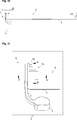
- FIGS. 1a to 1d – are schematic views of a manufacturing process of a door by using a handle-assembly according to an embodiment of the present invention
- Figure 2 – is a schematic enlarged partial perspective view of the handle-assembly shown in Figs.1a to 1d;
- Figure 3 – is a schematic top view of a handle and a connector of the handle-assembly shown in Fig. 2;
- Figure 8 – is a schematic cross-sectional view of the counterpart connector shown in Fig. 4, taken along the line C-C;
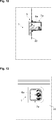
- Figure 13 — is a schematic cross-sectional view of the handle-assembly and the cover plate shown in Fig. 11, taken along the line G-G.
- the counterpart connector (7a, 7b) is separately provided from connector (6a, 6b).
- the counterpart connector (7a, 7b) includes a cavity (8), and a counterpart snap-fit portion (9) which is provided inside the cavity (8).
- the counterpart connector (7a, 7b) abuts against an inner surface (10) of the cover plate (3) such that an opening (11) of the cavity (8) coincides with the through-hole (4a, 4b, 4a ⁇ , 4b ⁇ ).
- the connector (6a,6b) includes a snap-fit portion (12) which protrudes through the through-hole (4a, 4b, 4a ⁇ , 4b ⁇ ) into the cavity (8) of the counterpart connector (7a, 7b).
- the snap-fit portion (12) and the counterpart snap-fit portion (9) are releasably engageable (Figs. 1 to 13).
- the counterpart snap-fit portion (9) has two locking hooks (14) which extend vertically upwards.
- the snap fit-portion (12) has two locking slots (15) which respectively oppose the locking hooks (14) in a state where the snap-fit portion (12) protrudes into the cavity (8) (Fig. 2).
- locking hooks (14) and the locking slots (15) releasably engage with each other when the snap-fit portion (12) is displaced from the upper portion (13a) to the lower portion (13b) by manually moving the handle (5) vertically downwards, and disengage from each other when the snap-fit portion (12) is displaced from the lower portion (13b) to the upper portion (13a) by manually moving the handle (5) vertically upwards (Fig. 2, Figs. 10 to 13).
- the counterpart connector (7a, 7b) has a seat (20) which surrounds the opening (11) of the cavity (8).
- the seat (20) circumferentially abuts against an inner surface (10) of the cover plate (3) which surrounds the through-hole (4a, 4b, 4a ⁇ , 4b ⁇ ) (Fig. 2, Figs.10 to 13).
- the handle-assembly (1) is selectively mountable to the door (2) for either left-hand swing or right-hand swing (Fig. 1a).
- the counterpart connector (7a, 7b) is abutted against an inner surface (10) of the cover plate (3) such that an opening (11) of the cavity (8) coincides with the through-hole (4a, 4b, 4a ⁇ , 4b ⁇ ).
- foam material has been filled into an inner space (21) of the door (2) such that the counterpart connector (7a, 7b) is immobilized relative to the cover plate (3) by the cured foam material (Fig. 1b).
- At least one through-hole (4a, 4a ⁇ , 4b, 4b ⁇ ) is formed on each of a left-lateral side (22) and a right-lateral side (23) of the cover plate (3) for selectively mounting the handle (5) to the door (2) for either left-hand swing or right-hand swing (Fig. 1a).
- the present invention also provides a refrigeration appliance (not shown) which comprises a main body which includes a refrigeration compartment for receiving articles to be refrigerated, and the door (2) for enabling access to an interior of the refrigeration compartment.
- a refrigeration appliance (not shown) which comprises a main body which includes a refrigeration compartment for receiving articles to be refrigerated, and the door (2) for enabling access to an interior of the refrigeration compartment.
- the manufacturing process comprises a step of mounting the handle (5) by connecting the connector (6a, 6b) with the counterpart connector (7a, 7b) (Fig. 1c).
- a screwless handle-assembly (1) has been provided which reduces the costs for material and labor. Due to the quick and simple installation of the handle (5), the assemblage and transportation of the refrigeration appliance has been facilitated and rendered safer.
- the handle (5) can be easily mounted by a service person in accordance with the swinging direction without the burden of time consuming assembly steps involving unscrewing/screwing of bolts.
Landscapes
- Engineering & Computer Science (AREA)
- Chemical & Material Sciences (AREA)
- Combustion & Propulsion (AREA)
- Physics & Mathematics (AREA)
- Mechanical Engineering (AREA)
- Thermal Sciences (AREA)
- General Engineering & Computer Science (AREA)
- Refrigerator Housings (AREA)
Abstract
The present invention relates to a handle-assembly (1) for use in a door (2) of a refrigeration appliance. The door (2) comprises a cover plate (3) which has a through-hole (4a, 4b, 4a', 4b') for mounting a handle (5). In the handle-assembly (1) of the present invention, the handle (5) has a connector (6a, 6b) which has a snap-fit portion (12) which protrudes through a through-hole (4a, 4b, 4a', 4b') and snap-fittingly engages with a counterpart snap-fit portion (9) of a counterpart connector (7a, 7b) which is arranged inside the door (2).
Description
The present invention relates to a handle-assembly for use in a door, in particular a reversible door of a refrigeration appliance such as a domestic refrigerator in which the door can be selectively mounted by a user for left-hand swing or right-hand swing. The present invention also relates to a process of manufacturing the door by using the handle-assembly.
It is common practice to provide a refrigeration appliance such as a domestic refrigerator with a reversible hinge system and a reversible handle which together allow a customer to selectively mount the pivotable door to a main body of the appliance for either left-hand or right-hand swing. When a customer purchases a domestic refrigerator, the swing direction of the door thereof may not always conform to the customer’s kitchen layout. Nevertheless, the customer may change by virtue of the reversible hinge system and the reversible handle, the swing direction of the door prior to installing the refrigerator at its designated location in the kitchen such that the door opens and closes in conformity with the kitchen layout.
In such domestic refrigerators, elements like the hinges, the handle, the plugs, the covers, the washers, and the spacers are all rendered transferrable from one side of the main body to an opposite side of the main body when reversing the swing direction of the door. Thereby, the customer is enabled to easily reverse a swing direction of the door without the need of extra elements.
The customer generally removes any plugs which conceal the demountable elements of the hinge system in order to change the swing direction of the door. Subsequently, the customer demounts the reversible handle, the reversible hinges including any washers and spacers from their current position on the main body and re-mounts the same to an opposite position on the main body.
EP 1 153 557 A1 discloses a handle for a refrigerator appliance. This handle has a couple of through-holes for mounting it to the door of the refrigeration appliance by utilizing a couple of corresponding bolts.
A drawback of this type of a handle is that the screws increase the manufacturing costs including the costs for material and labor.
An objective of the present invention is to provide a handle-assembly and a door having the same which overcomes the aforementioned drawbacks of the prior art and which enables a quick and reliable installation of the handle. Another objective of the present invention is to provide a process for manufacturing the door by using the handle-assembly.
This objective have been achieved by the handle-assembly as defined in claim 1, the door as defined in claim 9, the refrigeration appliance as defined in claim 13, and the manufacturing process as defined in claim 14. Further achievements have been attained by the subject-matters respectively defined in the dependent claims.
In the handle-assembly of the present invention, the handle has a connector which has a snap-fit portion which protrudes through a through-hole in a cover pate of the door and snap-fittingly engages with a counterpart snap-fit portion of a counterpart connector arranged inside the door. The connector and counterpart connector are provided separately from each other. In the handle-assembly of the present invention the counterpart snap-fit portion is formed in a cavity of the counterpart connector which has an opening that is arranged to face the through-hole.
The present invention also provides a process of manufacturing the door by using the handle-assembly. In the manufacturing process of the present invention the counterpart connector is immobilized relative to the cover plate by injecting foam into inner space of the door such that in the cured state of the foam the opening of the cavity faces the through-hole.
In an embodiment, the handle-assembly has a pair of connectors and a pair of counterpart connectors. The connectors are integrally provided with the opposing arms of the handle, and the counterpart connectors are arranged on one of a lateral side of the door. In a version of the embodiment, the door is rendered reversible and has an additional pair of counterpart connectors which is arranged on the other lateral side of the door. Thus, the user can selectively mount the handle to one of the lateral sides. In another version this embodiment, the unused through-holes are closed by removable plugs.
In another embodiment, the cavity has a clearance. In this embodiment, in a state where the snap-fit portion is received by the cavity, the snap-fit portion and the counterpart snap-fit portion get engaged or disengaged by manually moving the handle downwards or upwards respectively.
By the present invention, a handle-assembly has been provided which can be easily installed by using foam material. Thereby, the use of screws has been obviated and the costs for material and labor have been reduced. Due to the simplified installation of the handle, the refrigeration appliance can transported to its designated location in a state where the handle is temporally stored in a refrigeration appliance. Thus, the handle can be taken out of the refrigeration compartment and quickly mounted by a service person to the door. Thereby, the transportation becomes easier. In addition, the handle can be easily mounted on a desired lateral side of the door so as to either enable left-hand swing or right hand swing without the burden of unscrewing/screwing bolts or the like. In the door of the present invention, the counterpart connector does not protrude out of the through-hole of the cover plate, thus, a risk of damaging the same in a state where the handle is taken off during transportation has been eliminated.
Additional advantages of the handle-assembly of the present invention and the manufacturing process of the door by using the handle-assembly of the present invention will become apparent with the detailed description of the embodiments with reference to the accompanying drawings in which:
Figures 1a to 1d – are schematic views of a manufacturing process of a door by using a handle-assembly according to an embodiment of the present invention;
Figure 2 – is a schematic enlarged partial perspective view of the handle-assembly shown in Figs.1a to 1d;
Figure 3 – is a schematic top view of a handle and a connector of the handle-assembly shown in Fig. 2;
Figure 4 – is a schematic top view of a counterpart connector of the handle-assembly shown in Fig. 2;
Figure 5 – is a schematic front view of the counterpart connector shown in Fig. 2;
Figure 6 – is a schematic cross-sectional view of the handle and the connector shown in Fig. 3, taken along the line A-A;
Figure 7 – is a schematic cross-sectional view of the handle and the connector shown in Fig. 3, taken along the line B-B;
Figure 8 – is a schematic cross-sectional view of the counterpart connector shown in Fig. 4, taken along the line C-C;
Figure 9 – is a schematic cross-sectional view of the counterpart connector shown in Fig. 4, taken along the line D-D;
Figure 10 – is a schematic top view of the door shown in Figs. 1c to 1d;
Figure 11 – is a schematic enlarged view of the detail E of Fig. 10;
Figure 12 – is a schematic cross-sectional view of the handle-assembly and the cover plate shown in Fig. 11, taken along the line F-F;
Figure 13 – is a schematic cross-sectional view of the handle-assembly and the cover plate shown in Fig. 11, taken along the line G-G.
The reference signs appearing on the drawings relate to the following technical features.
- Handle-assembly
- Door
- Cover plate
4a. Through-hole
4b. Through-hole
4a´ Through-hole
4a´ Through-hole
4b´ Through-hole
5. Handle
6a. Connector
6b. Connector
6b. Connector
7a. Counterpart Connector
7b. Counterpart Connector
8. Cavity
9. Counterpart snap-fit portion
10. Inner surface
11. Opening
12. Snap-fit portion
13a. Upper portion
13b. Lower portion
13b. Lower portion
14. Locking hooks
15. Locking slots
16. Undercut
17. Projections
18. Guiding channel
19. Guiding protrusion
20. Seat
21. Inner space
22. Left-lateral side
23. Right-lateral side
The handle-assembly (1) is suitable for use in a door (2) of a refrigeration appliance (Figs. 1a, 1b, 1c, 1d and Fig. 2).
The door (2) is suitable for use in a refrigeration appliance, in particular a domestic refrigerator to enable access to an interior of a refrigeration compartment thereof. The door (2) comprises a handle-assembly (1), and a cover plate (3) which has at least one through-hole (4a, 4b, 4a´, 4b´) for mounting a handle (5) of the handle-assembly (1) (Fig. 1).
The handle-assembly (1) of the present invention comprises a handle (5) which has a connector (6a, 6b) corresponding to the through-hole (4a, 4b, 4a´, 4b´), and a counterpart connector (7a, 7b) for releasable connection with the connector (6a, 6b).
The counterpart connector (7a, 7b) is separately provided from connector (6a, 6b). The counterpart connector (7a, 7b) includes a cavity (8), and a counterpart snap-fit portion (9) which is provided inside the cavity (8). The counterpart connector (7a, 7b) abuts against an inner surface (10) of the cover plate (3) such that an opening (11) of the cavity (8) coincides with the through-hole (4a, 4b, 4a´, 4b´). The connector (6a,6b) includes a snap-fit portion (12) which protrudes through the through-hole (4a, 4b, 4a´, 4b´) into the cavity (8) of the counterpart connector (7a, 7b). The snap-fit portion (12) and the counterpart snap-fit portion (9) are releasably engageable (Figs. 1 to 13).
In an embodiment, the cavity (8) includes an upper portion (13a) and lower portion (13b). The upper portion (13a) horizontally receives the snap-fit portion (12). The counterpart snap-fit portion (9) is formed into the lower portion (13b). In this embodiment, the snap-fit portion (12) and the counterpart snap-fit portion (9) releasably engage with each other when the snap-fit portion (12) is displaced from the upper portion (13a) to the lower portion (13b) by manually moving the handle (5) vertically downwards, and disengage from each other when the snap-fit portion (12) is displaced from the lower portion (13b) to the upper portion (13a) by manually moving the handle (5) vertically upwards (Fig. 1b, Figs. 10 to 13).
In another embodiment, the counterpart snap-fit portion (9) has two locking hooks (14) which extend vertically upwards. In this embodiment, the snap fit-portion (12) has two locking slots (15) which respectively oppose the locking hooks (14) in a state where the snap-fit portion (12) protrudes into the cavity (8) (Fig. 2). In this embodiment, locking hooks (14) and the locking slots (15) releasably engage with each other when the snap-fit portion (12) is displaced from the upper portion (13a) to the lower portion (13b) by manually moving the handle (5) vertically downwards, and disengage from each other when the snap-fit portion (12) is displaced from the lower portion (13b) to the upper portion (13a) by manually moving the handle (5) vertically upwards (Fig. 2, Figs. 10 to 13).
In another embodiment, the connector (6a, 6b) has two opposing undercuts (16). In this embodiment, the counterpart connector (7a, 7b) has two opposing projections (17). The undercuts (16) and the projections (17) respectively engage with each other when the snap-fit portion (12) is displaced from the upper portion (13a) to the lower portion (13b) by manually moving the handle (5) vertically downwards, and disengage from each other when the snap-fit portion (12) is displaced from the lower portion (13b) to the upper portion (13) by manually moving the handle (5) vertically upwards (Fig. 2, Figs.10 to 13).
In another embodiment, the connector (6a, 6b) has a guiding channel (18) which extends in a vertical direction. In this embodiment, the counterpart connector (7a, 7b) has a guiding protrusion (19) which extends in a vertical direction. The guiding channel (18) and the guiding protrusion (19) slidably engage with each other when the snap-fit portion (12) is displaced from the upper portion (13a) to the lower portion (13b) by manually moving the handle (5) vertically downwards, and disengage from each other when the snap-fit portion (12) is displaced from the lower portion (13b) to the upper portion (13a) by manually moving the handle (5) vertically upwards (Fig. 2, Figs.10 to 13).
In another embodiment, the counterpart connector (7a, 7b) has a seat (20) which surrounds the opening (11) of the cavity (8). In this embodiment, the seat (20) circumferentially abuts against an inner surface (10) of the cover plate (3) which surrounds the through-hole (4a, 4b, 4a´, 4b´) (Fig. 2, Figs.10 to 13).
In another embodiment, the handle-assembly (1) has two connectors (6a, 6b) and two counterpart connectors (7a, 7b). In this embodiment, the two connectors (6a, 6b) are formed on opposing ends of the handle (5) in order to cooperate with the two counterpart connectors (7a, 7b) respectively via two corresponding through-holes (4a, 4b, 4a´, 4b´) which are formed into the cover plate (3) (Fig. 1).
In another embodiment, the handle-assembly (1) is selectively mountable to the door (2) for either left-hand swing or right-hand swing (Fig. 1a).
In the door (2) of the present invention, the counterpart connector (7a, 7b) is abutted against an inner surface (10) of the cover plate (3) such that an opening (11) of the cavity (8) coincides with the through-hole (4a, 4b, 4a´, 4b´). In addition, foam material has been filled into an inner space (21) of the door (2) such that the counterpart connector (7a, 7b) is immobilized relative to the cover plate (3) by the cured foam material (Fig. 1b).
In another embodiment, the door (2) comprises a reversible hinge system (not shown) for selectively mounting it to the refrigeration appliance for either left hand swing or right-hand swing.
In another embodiment, at least one through-hole (4a, 4a´, 4b, 4b´) is formed on each of a left-lateral side (22) and a right-lateral side (23) of the cover plate (3) for selectively mounting the handle (5) to the door (2) for either left-hand swing or right-hand swing (Fig. 1a).
In another embodiment, any unused through-hole (4a, 4a´, 4b, 4b´) is closed by a plug (not shown).
The present invention also provides a refrigeration appliance (not shown) which comprises a main body which includes a refrigeration compartment for receiving articles to be refrigerated, and the door (2) for enabling access to an interior of the refrigeration compartment.
In another embodiment, the refrigeration appliance comprises a reversible hinge system (not shown) for selectively mounting the door (2) to the main body of the appliance for either left-hand or right-hand swing. In this embodiment, the door (2) has a corresponding reversible hinge system (not shown) for selectively mounting it to the main body of the appliance for either left-hand or right-hand swing.
The present invention also provides a process of manufacturing the door (2) for use in the refrigeration appliance by using the handle-assembly (1).
In the manufacturing process, first the door (2) comprising the cover plate (3) which has the through hole (4a, 4a´, 4b, 4b´) for mounting the handle (5) is provided (Fig. 1a). Then, the counterpart connector (7a, 7b) is abutted against an inner surface (10) of the cover plate (3) such that the opening (11) of the cavity (8) faces the through-hole (4a, 4a´, 4b, 4b´) (Fig. 1b). Then, foam material is poured (not shown) into an inner space (21) which is enclosed by the door (2) in order to immobilize the counterpart connector (7a, 7b) relative to the cover plate (3) as the foam material is cured.
In another embodiment, the manufacturing process comprises a step of mounting the handle (5) by connecting the connector (6a, 6b) with the counterpart connector (7a, 7b) (Fig. 1c).
By the present invention, a screwless handle-assembly (1) has been provided which reduces the costs for material and labor. Due to the quick and simple installation of the handle (5), the assemblage and transportation of the refrigeration appliance has been facilitated and rendered safer. The handle (5) can be easily mounted by a service person in accordance with the swinging direction without the burden of time consuming assembly steps involving unscrewing/screwing of bolts.
Claims (15)
- A handle-assembly (1) for use in a door (2) of a refrigeration appliance, the door (2) comprising a cover plate (3) which has a through-hole (4a, 4b, 4a´, 4b´) for mounting a handle (5), the handle-assembly (1), characterized in that- a handle (5) which has a connector (6a,6b) corresponding to the through-hole (4a, 4b, 4a´, 4b´),- a counterpart connector (7a, 7b) for releasably connecting with the connector (6a, 6b), wherein the counterpart connector (7a, 7b) is separately provided from connector (6a,6b),wherein said counterpart connector (7a, 7b) includes a cavity (8) and a counterpart snap-fit portion (9) which is provided inside the cavity (8),wherein the counterpart connector (7a, 7b) is configured to abut against an inner surface (10) of the cover plate (3) such that an opening (11) of the cavity (8) coincides with the through-hole (4a, 4b, 4a´, 4b´),wherein the connector (6a,6b) includes a snap-fit portion (12) which is configured to protrude through the through-hole (4a, 4b, 4a´, 4b´) into the cavity (8) of the counterpart connector (7a,7b), andwherein the snap-fit portion (12) and the counterpart snap-fit portion (9) are releasably engageable.
- The handle-assembly (1) according to claim 1, characterized in that- the cavity (8) includes an upper portion (13a) which is configured to horizontally receive the snap-fit portion (12), and a lower portion (13b) into which the counterpart snap-fit portion (9) is formed,wherein the snap-fit portion (12) and the counterpart snap-fit portion (9) are configured to releasably engage with each other when the snap-fit portion (12) is displaced from the upper portion (13a) to the lower portion (13b) by manually moving the handle (5) vertically downwards, and to disengage from each other when the snap-fit portion (12) is displaced from the lower portion (13b) to the upper portion (13a) by manually moving the handle (5) vertically upwards.
- The handle-assembly (1) according to claim 2, characterized in that- the counterpart snap-fit portion (9) has two locking hooks (14) which are configured to extend vertically upwards and- the snap fit-portion (12) has two locking slots (15) which are configured to respectively oppose the locking hooks (14) in a state where the snap-fit portion (12) protrudes into the cavity (8).
- The handle-assembly (1) according to claim 2 or 3, characterized in that- the connector (6a,6b) has two opposing undercuts (16), and- the counterpart connector (7a, 7b) has two opposing projections (17),wherein the undercuts (16) and the projections (17) are configured to respectively engage with each other when the snap-fit portion (12) is displaced from the upper portion (13a) to the lower portion (13b) by manually moving the handle (5) vertically downwards, and to disengage from each other when the snap-fit portion (12) is displaced from the lower portion (13b) to the upper portion (13) by manually moving the handle (5) vertically upwards.
- The handle-assembly (1) according to any one of claims 2 to 4, characterized in that- the connector (6a,6b) has a guiding channel (18) which is configured to extend in a vertical direction, and- the counterpart connector (7a,7b) has a guiding protrusion (19) which is configured to extend in a vertical direction,wherein the guiding channel (18) and the guiding protrusion (19) are configured to slidably engage with each other when the snap-fit portion (12) is displaced from the upper portion (13a) to the lower portion (13b) by manually moving the handle (5) vertically downwards, and to disengage from each other when the snap-fit portion (12) is displaced from the lower portion (13b) to the upper portion (13a) by manually moving the handle (5) vertically upwards.
- The handle-assembly (1) according to any one of claims 1 to 5, characterized in that the counterpart connector (7a,7b) has a seat (20) which is configured to surround the opening (11) of the cavity (8), and to circumferentially abut against an inner surface (10) of the cover plate (3) which surrounds the through-hole (4a, 4b, 4a´, 4b´).
- The handle-assembly (1) according to any one of claims 1 to 6, characterized in that two connectors (6a, 6b) and two counterpart connectors (7a, 7b), wherein the two connectors (6a, 6b) are formed on opposing ends of the handle (5) so as to cooperate with the two counterpart connectors (7a, 7b) respectively via two corresponding through-holes (4a, 4b, 4a´, 4b´) which are formed into the cover plate (3).
- The handle-assembly (1) according to any one of claims 1 to 7, characterized in that the handle-assembly (1) is configured to be selectively mountable to the door (2) for either left-hand swing or right-hand swing.
- A door (2) for use in a refrigeration appliance to enable access to an interior of a refrigeration compartment, the door (2) comprisinga cover plate (3) which has a through-hole (4a, 4b, 4a´, 4b´) for mounting a handle (5),characterized in that- a handle-assembly (1) as defined in any one of claims 1 to 8, wherein- the counterpart connector (7a,7b) is abutted against an inner surface (10) of the cover plate (3) such that an opening (11) of the cavity (8) coincides with the through-hole (4a, 4b, 4a´, 4b´) and- foam material which has been filled into an inner space (21) of the door (2), wherein the counterpart connector (7a,7b) is immobilized relative to the cover plate (3) by the foam material.
- The door (2) according to claim 9, characterized in that a reversible hinge system for selectively mounting the door (2) to the refrigeration appliance for either left hand swing or right-hand swing.
- The door (2) according to claim 10, characterized in that at least one through-hole (4a, 4a´, 4b, 4b´) is formed on each of a left-lateral side (22) and a right-lateral side (22´) of the cover plate (3) for selectively mounting the handle (5) to the door (2) for either left hand swing or right-hand swing.
- The door (2) according to claim 11, characterized in that an unused through-holes (4a, 4a´, 4b, 4b´) is closed by a plug.
- A refrigeration appliance characterized in that the door (2) as defined in any one of claims 9 to 12.
- A process of manufacturing a door (2) for use in a refrigeration appliance by using the handle-assembly (1) as defined in any one of claims 1 to 8, the method comprising the steps of:- providing a door (2) comprising a cover plate (3) which has a through hole (4a, 4a´, 4b, 4b´) for mounting a handle (5),- a step of abutting the counterpart connector (7a,7b) against an inner surface (10) of the cover plate (3) such that the opening (11) of the cavity (8) faces the through-hole (4a, 4a´, 4b, 4b´) and- pouring foam material into an inner space (21) which is enclosed by the door (2) in order to immobilize the counterpart connector (7a,7b) relative to the cover plate (3) as the foam material is cured.
- The manufacturing process according to claim 14, characterized by further comprising a step of mounting the handle (5) by connecting the connector (6a, 6b) with the counterpart connector (7a, 7b).
Priority Applications (2)
| Application Number | Priority Date | Filing Date | Title |
|---|---|---|---|
| EP14713480.3A EP3123087A1 (en) | 2014-03-28 | 2014-03-28 | Improved handle assembly for refrigeration appliance door |
| PCT/EP2014/056346 WO2015144247A1 (en) | 2014-03-28 | 2014-03-28 | Improved handle assembly for refrigeration appliance door |
Applications Claiming Priority (1)
| Application Number | Priority Date | Filing Date | Title |
|---|---|---|---|
| PCT/EP2014/056346 WO2015144247A1 (en) | 2014-03-28 | 2014-03-28 | Improved handle assembly for refrigeration appliance door |
Publications (1)
| Publication Number | Publication Date |
|---|---|
| WO2015144247A1 true WO2015144247A1 (en) | 2015-10-01 |
Family
ID=50390105
Family Applications (1)
| Application Number | Title | Priority Date | Filing Date |
|---|---|---|---|
| PCT/EP2014/056346 WO2015144247A1 (en) | 2014-03-28 | 2014-03-28 | Improved handle assembly for refrigeration appliance door |
Country Status (2)
| Country | Link |
|---|---|
| EP (1) | EP3123087A1 (en) |
| WO (1) | WO2015144247A1 (en) |
Cited By (8)
| Publication number | Priority date | Publication date | Assignee | Title |
|---|---|---|---|---|
| CN111719942A (en) * | 2019-03-22 | 2020-09-29 | 青岛海尔洗碗机有限公司 | Handle mounting structure for household appliance and household appliance |
| WO2020224851A1 (en) * | 2019-05-07 | 2020-11-12 | Arcelik Anonim Sirketi | A refrigerator comprising a door handle |
| CN112681884A (en) * | 2020-12-03 | 2021-04-20 | 杭州康利达卫浴有限公司 | Connect device and door handle soon |
| EP3904794A1 (en) | 2020-04-29 | 2021-11-03 | Arçelik Anonim Sirketi | A cooling appliance having an improved handle |
| EP3933316A1 (en) | 2020-06-29 | 2022-01-05 | Arçelik Anonim Sirketi | A cooling appliance having an improved handle mechanism |
| EP3933317A1 (en) | 2020-06-29 | 2022-01-05 | Arçelik Anonim Sirketi | A cooling appliance having an improved handle mechanism |
| US20230148387A1 (en) * | 2021-11-08 | 2023-05-11 | Haier Us Appliance Solutions, Inc. | Slide and lock appliance handle mounting |
| EP4202326A1 (en) | 2021-12-27 | 2023-06-28 | Arçelik Anonim Sirketi | A cooling device |
Citations (7)
| Publication number | Priority date | Publication date | Assignee | Title |
|---|---|---|---|---|
| US4534530A (en) * | 1984-03-19 | 1985-08-13 | Phillips Plastics Corporation | Support assembly and apparatus using same |
| EP1153557A1 (en) | 2000-04-28 | 2001-11-14 | Liebherr-Hausgeräte Gmbh | Door handle, preferably hand grip for the door of a refrigerator or freezer |
| US20050120689A1 (en) * | 2002-07-22 | 2005-06-09 | Bsh Bosch Und Siemens Hausgerate Gmbh | Fastening element and arrangement |
| KR20070065743A (en) * | 2005-12-20 | 2007-06-25 | 주식회사 대우일렉트로닉스 | Structure for mounting door handle in refrigertor |
| WO2010150855A1 (en) * | 2009-06-25 | 2010-12-29 | 株式会社ニフコ | Fixture |
| WO2012175732A2 (en) * | 2011-06-23 | 2012-12-27 | Arcelik Anonim Sirketi | A cooling device comprising an easily mountable handle |
| WO2013000977A2 (en) * | 2011-06-27 | 2013-01-03 | Arcelik Anonim Sirketi | A cooling device wherein the opening direction of the door can be changed |
Family Cites Families (1)
| Publication number | Priority date | Publication date | Assignee | Title |
|---|---|---|---|---|
| AU2008216999B2 (en) * | 2007-10-25 | 2014-11-13 | Aktiebolaget Electrolux | A Handle Assembly |
-
2014
- 2014-03-28 EP EP14713480.3A patent/EP3123087A1/en not_active Withdrawn
- 2014-03-28 WO PCT/EP2014/056346 patent/WO2015144247A1/en active Application Filing
Patent Citations (7)
| Publication number | Priority date | Publication date | Assignee | Title |
|---|---|---|---|---|
| US4534530A (en) * | 1984-03-19 | 1985-08-13 | Phillips Plastics Corporation | Support assembly and apparatus using same |
| EP1153557A1 (en) | 2000-04-28 | 2001-11-14 | Liebherr-Hausgeräte Gmbh | Door handle, preferably hand grip for the door of a refrigerator or freezer |
| US20050120689A1 (en) * | 2002-07-22 | 2005-06-09 | Bsh Bosch Und Siemens Hausgerate Gmbh | Fastening element and arrangement |
| KR20070065743A (en) * | 2005-12-20 | 2007-06-25 | 주식회사 대우일렉트로닉스 | Structure for mounting door handle in refrigertor |
| WO2010150855A1 (en) * | 2009-06-25 | 2010-12-29 | 株式会社ニフコ | Fixture |
| WO2012175732A2 (en) * | 2011-06-23 | 2012-12-27 | Arcelik Anonim Sirketi | A cooling device comprising an easily mountable handle |
| WO2013000977A2 (en) * | 2011-06-27 | 2013-01-03 | Arcelik Anonim Sirketi | A cooling device wherein the opening direction of the door can be changed |
Non-Patent Citations (1)
| Title |
|---|
| See also references of EP3123087A1 * |
Cited By (9)
| Publication number | Priority date | Publication date | Assignee | Title |
|---|---|---|---|---|
| CN111719942A (en) * | 2019-03-22 | 2020-09-29 | 青岛海尔洗碗机有限公司 | Handle mounting structure for household appliance and household appliance |
| WO2020224851A1 (en) * | 2019-05-07 | 2020-11-12 | Arcelik Anonim Sirketi | A refrigerator comprising a door handle |
| EP3904794A1 (en) | 2020-04-29 | 2021-11-03 | Arçelik Anonim Sirketi | A cooling appliance having an improved handle |
| EP3933316A1 (en) | 2020-06-29 | 2022-01-05 | Arçelik Anonim Sirketi | A cooling appliance having an improved handle mechanism |
| EP3933317A1 (en) | 2020-06-29 | 2022-01-05 | Arçelik Anonim Sirketi | A cooling appliance having an improved handle mechanism |
| CN112681884A (en) * | 2020-12-03 | 2021-04-20 | 杭州康利达卫浴有限公司 | Connect device and door handle soon |
| CN112681884B (en) * | 2020-12-03 | 2022-07-19 | 杭州康利达卫浴有限公司 | Connect device and door handle soon |
| US20230148387A1 (en) * | 2021-11-08 | 2023-05-11 | Haier Us Appliance Solutions, Inc. | Slide and lock appliance handle mounting |
| EP4202326A1 (en) | 2021-12-27 | 2023-06-28 | Arçelik Anonim Sirketi | A cooling device |
Also Published As
| Publication number | Publication date |
|---|---|
| EP3123087A1 (en) | 2017-02-01 |
Similar Documents
| Publication | Publication Date | Title |
|---|---|---|
| WO2015144247A1 (en) | Improved handle assembly for refrigeration appliance door | |
| EP3809073B1 (en) | Refrigerator | |
| US8732910B1 (en) | Appliance handle assembly | |
| RU2347159C2 (en) | Refrigerator cabinet and method of its production | |
| US20090179539A1 (en) | Refrigerator door stop | |
| EP2447454B1 (en) | Hinge device and ultra-deep freezer using the same | |
| KR101349986B1 (en) | A lead wire connecting structure for refrigerator | |
| RU2310105C2 (en) | Fastening element and fastening system | |
| CN106766534B (en) | Insulation can for refrigeration equipment and refrigeration equipment | |
| WO2021080704A1 (en) | Door end closure assembly with integrated user interface | |
| US20190203948A1 (en) | Food cooking oven | |
| EP3784962B1 (en) | Domestic refrigeration appliance comprising a backing part, and method for producing said domestic refrigeration appliance | |
| KR20160067563A (en) | Refrigerator | |
| US9810474B2 (en) | Joint members for refrigerator appliance casings | |
| US8516659B2 (en) | Refrigerator handle mounting arrangement having pin and cavity interlock | |
| WO2020238259A1 (en) | Refrigerator having slide rail cabling mechanism | |
| KR20190106494A (en) | Refrigerator | |
| CN103486114B (en) | Mechanical connecting device and household electrical appliance for household electrical appliance combine | |
| US20090260390A1 (en) | Refrigerator and/or Freezer | |
| KR200254215Y1 (en) | Door of refrigerator for cabbage and radish pickle | |
| EP3278044B1 (en) | Protective casing assembly for refrigerator display | |
| CN217154645U (en) | Refrigeration device | |
| US9228774B1 (en) | Concealed mount for refrigerator appliance door panel | |
| CN111503979A (en) | Door body, refrigeration equipment and assembly method of door body | |
| CN103162486B (en) | The manufacture method of the heat insulating member of refrigerating appliance and refrigerating appliance |
Legal Events
| Date | Code | Title | Description |
|---|---|---|---|
| 121 | Ep: the epo has been informed by wipo that ep was designated in this application |
Ref document number: 14713480 Country of ref document: EP Kind code of ref document: A1 |
|
| REEP | Request for entry into the european phase |
Ref document number: 2014713480 Country of ref document: EP |
|
| WWE | Wipo information: entry into national phase |
Ref document number: 2014713480 Country of ref document: EP |
|
| NENP | Non-entry into the national phase |
Ref country code: DE |