Dispositif et procédé de filtrage du pic de résonance dans un circuit d'alimentation d'au moins un haut-parleur en amont de celui-ci Device and method for filtering the resonance peak in a supply circuit of at least one speaker upstream thereof
La présente invention concerne un dispositif et un procédé de filtrage du pic de résonance dans un circuit d'alimentation d'au moins un haut-parleur, le dispositif de filtrage étant disposé en amont dudit au moins un haut-parleur. The present invention relates to a device and a method for filtering the resonant peak in a supply circuit of at least one loudspeaker, the filtering device being disposed upstream of said at least one loudspeaker.
On sait qu'un haut-parleur classique comprend un actionneur électromagnétique, le plus souvent composé d'un bobinage disposé sur un équipage mobile au sein d'un champ magnétique généré par un aimant permanent. It is known that a conventional loudspeaker comprises an electromagnetic actuator, most often composed of a coil disposed on a moving element within a magnetic field generated by a permanent magnet.
Lorsque le bobinage du haut-parleur est parcouru par un courant modulé en fréquence, le déplacement mécanique induit à fréquence audible est transformé en champ acoustique au moyen d'une membrane jouant le rôle de surface émissive, également appelée radiateur acoustique. When the winding of the loudspeaker is traversed by a frequency-modulated current, the audible frequency induced mechanical displacement is transformed into an acoustic field by means of a membrane acting as an emitting surface, also called an acoustic radiator.
La qualité sonore du haut-parleur dépend de la courbe de réponse en fréquence, c'est-à-dire une réponse mécanique en accélération à une sollicitation électrique soit en courant soit en tension, que l'on recherche la plus constante possible sur l'ensemble de la bande passante. La qualité sonore dépend aussi de la linéarité du dispositif marquée par la présence d'un minimum de distorsions harmoniques et d'intermodulations. The sound quality of the loudspeaker depends on the frequency response curve, that is to say a mechanical response in acceleration to an electrical stress either current or voltage, which one seeks the most constant possible on the overall bandwidth. The sound quality also depends on the linearity of the device marked by the presence of a minimum of harmonic distortions and intermodulations.
Si le transducteur agissant en tant que haut-parleur favorise d'égale manière toutes les fréquences, la reproduction du timbre d'un instrument de musique, constitutif des harmoniques utiles du son, semble a priori pouvoir être assurée. If the transducer acting as a speaker favors all frequencies equally, the reproduction of the timbre of a musical instrument, constituting the useful harmonics of the sound, seems a priori to be assured.
Toutefois, la réalité se révèle plus complexe, compte tenu de la nécessité de reproduire convenablement les transitoires d'attaque des sons représentatifs de la signature acoustique des instruments de qualité. La réponse du haut-parleur aux transitoires est une condition essentielle de "fidélité" que l'on peut tester en détectant le "traînage" de la membrane lorsque le haut-parleur est sollicité par un train d'impulsions. L'inertie de l'équipage mobile et les forces dues aux phénomènes d'auto-induction participent à ce défaut. However, the reality is more complex, given the need to adequately reproduce the attack transients sounds representative of the acoustic signature of quality instruments. The response of the speaker to the transients is an essential condition of "fidelity" that can be tested by detecting the "drag" of the membrane when the loudspeaker is solicited by a train of pulses. The inertia of the moving equipment and the forces due to the phenomena of self-induction contribute to this defect.
Les mesures acoustiques, optiques et électriques montrent qu'il n'existe pas de haut-parleur idéal et que chaque réalisation présente des défauts en termes de limitation de bande passante, pointes de résonance diverses et d'inertie. Le couplage de plusieurs transducteurs permet en principe de pallier de nombreux défauts, mais,
à l'inverse, il arrive parfois de voir les défauts cumulés de façon rédhibitoire pour une reproduction musicale de qualité. The acoustic, optical and electrical measurements show that there is no ideal loudspeaker and that each embodiment has defects in terms of bandwidth limitation, various resonance peaks and inertia. The coupling of several transducers in principle makes it possible to overcome many defects, but, Conversely, it sometimes happens to see the accumulated defects unacceptable for quality musical reproduction.
Dans un haut-parleur, la force motrice utile à l'origine du déplacement de l'équipage mobile résulte de l'interaction du champ d'induction magnétique, noté B, avec chaque élément de longueur du bobinage traversé par un courant noté i(t) fonction d'un temps t. Sur le plan local, la force élémentaire appliquée sur un porteur de charge en déplacement au sein d'un champ d'induction est qualifiée de force de Lorentz et s'exerce dans une direction perpendiculaire au plan défini par le champ et la vitesse des porteurs. Un bilan au sein d'un volume élémentaire porteur de charges assujetti au phénomène conduit à l'expression :
In a loudspeaker, the useful motive force at the origin of the displacement of the moving element results from the interaction of the magnetic induction field, denoted B, with each element of length of the coil traversed by a current noted i ( t) function of a time t. At the local level, the elementary force applied to a load carrier moving within an induction field is called a Lorentz force and is exerted in a direction perpendicular to the plane defined by the field and the speed of the carriers. . A balance sheet within a basic volume carrying charges subject to the phenomenon leads to the expression:
Tout se passe comme si la longueur déroulée du bobinage, notée I, était exposée à un champ d'induction magnétique homogène, ce qui permet de définir la quantité Bl = B.l appelée facteur de force (en Newton par Ampère ou en Tesla.mètre) de la partie motrice du haut-parleur. It is as if the unrolled length of the winding, denoted I, was exposed to a homogeneous magnetic induction field, which makes it possible to define the quantity Bl = Bl called the force factor (in Newton per Ampere or in Tesla.meter) the driving part of the speaker.
Cette force, modulée par l'intensité, sollicite l'équipage mobile dont le comportement mécanique est dicté par trois composantes : une force d'inertie, produit de la masse des parties en mouvement notée Mm par l'accélération imposée, une force d'amortissement, généralement considérée proportionnelle à la vitesse de déplacement via une constante notée fm en newton/m/s ou kg/s et une force de rappel liée la mécanique de suspension affectée d'une raideur notée km en N/m. Pour une translation guidée sur un axe x l'équation de comportement d'un tel transducteur idéalisé s'écrit :
This force, modulated by the intensity, solicits the mobile equipment whose mechanical behavior is dictated by three components: a force of inertia, product of the mass of moving parts noted M m by the imposed acceleration, a force of damping, generally considered proportional to the speed of movement via a constant denoted f m in newton / m / s or kg / s and a restoring force linked to the suspension mechanism with a stiffness denoted k m in N / m. For a guided translation on an x axis, the equation of behavior of such an idealized transducer is written:
La relation courant-tension aux bornes du haut-parleur est régie par sa structure caractérisée par l'équipage mobile en mouvement au sein d'un champ magnétique. Ainsi, le comportement électrique est dicté par deux mécanismes, à savoir la dissipation par effet Joule liée à la loi d'Ohm et les interactions électromagnétiques en termes de forces électromotrices induites, sous-tendus par trois contributions : The current-voltage relationship across the loudspeaker is governed by its structure characterized by the moving equipment moving within a magnetic field. Thus, the electrical behavior is dictated by two mechanisms, namely the Joule effect dissipation related to the Ohm's law and the electromagnetic interactions in terms of induced electromotive forces, underpinned by three contributions:
- la chute de tension liée à la composante résistive de l'enroulement solénoïde de l'équipage,
- la force électromotrice induite liée à la variation du flux magnétique lors du déplacement, the voltage drop related to the resistive component of the solenoid winding of the crew, the induced electromotive force linked to the variation of the magnetic flux during the displacement,
- la force électromotrice d'auto-induction régie par la loi de Lenz. - the electromotive force of self-induction governed by the law of Lenz.
Ainsi, dans l'hypothèse de linéarité du système, à l'équation précédemment indiquée régissant le comportement mécanique du haut-parieur, une équation de comportement électrique vient s'ajouter :
Thus, in the assumption of linearity of the system, to the aforementioned equation governing the mechanical behavior of the builder, an equation of electrical behavior is added:
Pour laquelle Re est la composante résistive pure de l'enroulement, susceptible de varier avec la température mesurée en Ohms et Le son inductance propre fonction du déplacement mesurée en Henry lorsque l'on tient compte des non linéarités. De fait, si le courant impliqué dans le membre de gauche de la deuxième équation découle directement de la troisième équation, alors toute perturbation ou non linéarité impliquée dans cette dernière entraîne une influence sur le déplacement de la membrane et ses fonctions dérivées. For which R e is the pure resistive component of the winding, which can vary with the temperature measured in Ohms and L e is its own inductance function of the displacement measured in Henry when nonlinearities are taken into account. In fact, if the current involved in the left-hand side of the second equation flows directly from the third equation, then any perturbation or non-linearity involved in the latter leads to an influence on the displacement of the membrane and its derived functions.
Il existe deux stratégies respectives de pilotage d'un haut-parleur, à savoir un pilotage en courant ou un pilotage en tension. Si, dans les deux cas, le traitement des signaux par les étages de pré-amplification conduisent à un signal de commande systématiquement mesurable sous la forme d'une tension, dans le cas d'une commande en tension, celle-ci est naturellement dépendante de l'impédance du dipôle que représente le transducteur faisant office de haut-parieur. Ce pilotage s'apparente à une liaison entre générateurs de Thévenin idéaux débitant sur le haut- parieur. Le haut-parleur constitue alors une charge tributaire d'une alimentation par impédance quasi-nulle et toute composante de force électromotrice ou f.e.m générée influence directement le courant traversant l'association. There are two respective strategies for controlling a loudspeaker, namely current control or voltage control. If, in both cases, the signal processing by the pre-amplification stages leads to a systematically measurable control signal in the form of a voltage, in the case of a voltage control, it is naturally dependent the impedance of the dipole represented by the transducer acting as high-wagerer. This piloting is similar to a link between the ideal Thévenin generators on the loudspeaker. The loudspeaker then constitutes a load dependent on a quasi-zero impedance supply and any generated electromotive force or f.e.m component directly influences the current flowing through the association.
A l'inverse, pour une commande en courant, la transduction tension courant est assurée par un conditionneur de signal spécifiquement agencé, le transducteur étant sollicité par le courant de sortie de ce conditionneur. Ce pilotage est assimilable à un générateur de Norton idéal débitant sur le transducteur : ce dernier représente alors une charge sollicitée sous impédance infinie, sur laquelle toute fluctuation de f.e.m. générée par la charge reste sans conséquence sur le comportement de l'association. Mieux encore, cette tension peut être mesurée puis utilisée en signal de correction dans une stratégie d'asservissement. Conversely, for current control, the current voltage transduction is provided by a specifically arranged signal conditioner, the transducer being biased by the output current of this conditioner. This control is comparable to an ideal Norton generator on the transducer: the latter then represents a load solicited under infinite impedance, on which any fluctuation of f.e.m. generated by the charge has no effect on the behavior of the association. More preferably, this voltage can be measured and then used as a correction signal in a servo strategy.
D'une manière générale le pilotage par commande en tension sollicite directement les haut-parleurs, compte tenu d'un comportement électrique assujetti
aux paramètres constitutifs de son impédance. Ce n'est que relativement récemment que divers travaux ont été conduits pour la conception de haut-parleurs spécifiquement pilotés en courant, compte tenu de conditionneurs adéquats. In general, control by voltage command directly solicits the speakers, given a subject electric behavior the constituent parameters of its impedance. It is only relatively recently that various works have been carried out for the design of specifically-driven loudspeakers, taking into account adequate conditioners.
Parmi les paramètres électriques et mécaniques représentatifs du comportement d'un haut-parieur, les trois grandeurs Bl, Re, Le précédemment mentionnées déterminent fondamentalement la qualité de reproduction de l'association conditionneur et transducteur. Les interactions ne seront pas les mêmes selon le choix réalisé par le concepteur parmi les deux modes de pilotage en courant et en tension. Among the electrical and mechanical parameters representative of the behavior of a loudspeaker, the three quantities Bl, R e , L e previously mentioned basically determine the reproduction quality of the conditioning and transducer association. The interactions will not be the same depending on the choice made by the designer among the two modes of current and voltage control.
Lors d'un pilotage en courant, l'association conditionneur-transducteur reste par nature totalement immune vis-à-vis des tensions générées. Pour un tel choix, il convient toutefois de détecter et de corriger si possible les défauts inhérents à l'altération des paramètres impliqués dans l'équation (2) qui en réalité présente un terme parasite de force fonction de l'intensité au carré ou i2 dite solénoïde selon la formule:
During current steering, the conditioner-transducer association remains by nature totally immune to the generated voltages. For such a choice, however, it is necessary to detect and correct, if possible, the defects inherent in the alteration of the parameters involved in equation (2), which in fact has a parasite term of force depending on the intensity squared or i 2 said solenoid according to the formula:
L'équation (2) peut s'écrire dans le domaine fréquence par :
Equation (2) can be written in the frequency domain by:
où X désigne la transformée du déplacement selon Làplace et I désigne I fois l'unité, le rapport fm/Mm étant représentatif de l'atténuation qui est la fonction inverse du temps de relaxation, alors que km/Mm traduit le carré de la fréquence angulaire de résonance. where X denotes the displacement transform according to Lheplace and I denotes I times the unit, the ratio f m / M m being representative of the attenuation which is the inverse function of the relaxation time, whereas k m / M m represents the square of the angular frequency of resonance.
En notant fm/Mm =
et km/Mm= w0 2, ω0 étant la vitesse angulaire initiale, la fonction de transfert du déplacement rapportée au courant s'exprime :
Noting f m / M m = and k m / M m = w 0 2 , where ω 0 is the initial angular velocity, the function of transfer of displacement relative to the current is expressed:
Les équations (2) et (3) peuvent être considérées dans le domaine fréquence en régime harmonique et combinées entre elles en termes de fonctions de transfert cascadées. En notant E0 et l0 les grandeurs complexes découplées de leur partie évolutive, l'indice étant significatif d'une fréquence angulaire particulière aussi appelée « phasors » en anglais, on obtient :
Equations (2) and (3) can be considered in the frequency domain in the harmonic regime and combined with each other in terms of cascaded transfer functions. Noting E 0 and l 0 the decoupled complex quantities of their evolutionary part, the index being significant of a particular angular frequency also called "phasors" in English, one obtains:
Après substitution du produit p.X dans la première relation, la fonction de transfert d'impédance apparaît immédiatement sous une forme composite impliquant deux termes :
After substitution of the product pX in the first relation, the impedance transfer function immediately appears in a composite form involving two terms:
Si la composante de réactance est négligée, alors l'impédance du haut- parleur peut être écrite :
If the reactance component is neglected, then the impedance of the loudspeaker can be written:
Le regroupement des paramètres conduit alors à la forme simple suivante The grouping of the parameters then leads to the following simple form
Il apparaît immédiatement que le polynôme V1 qui est celui représentatif du comportement lié au pilotage en tension est caractérisé par un amortissement a fortiori plus marqué que celui du polynôme P1 associé au régime de commande en courant. Au coefficient de frottement visqueux fm d'un régime de commande en courant est substitué pour un régime de commande en tension un coefficient systématiquement majoré tel que :
It immediately appears that the polynomial V 1 which is the one representative of the behavior related to the voltage control is characterized by a depreciation a fortiori more marked than that of the polynomial P 1 associated with the current control regime. The coefficient of viscous friction f m of a current control regime is substituted for a voltage control regime with a systematically increased coefficient such that:
Au regard des temps propres respectivement impliqués il est
With regard to the respective times respectively involved it is
défini des facteurs de résonance mécanique Qm et Qm+e, tels que :
Un coefficient spécifiquement électrique Qe peut donc être défini en faisant tendre fm vers zéro et une relation simple couplant les facteurs de résonance peut alors s'écrire :
defined mechanical resonance factors Q m and Q m + e , such as: A specific electrical coefficient Q e can therefore be defined by making f m close to zero and a simple relation coupling the resonance factors can then be written:
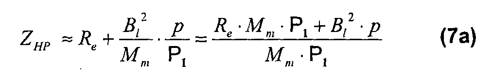
L'impédance du transducteur combine une composante exclusivement électrique avec une seconde composante appelée impédance motionnelle. Ainsi, l'impédance du haut-parleur ZHP s'écrit ZHP= Ze + Zm avec :
Transducer impedance combines an exclusively electrical component with a second component called motional impedance. Thus, the impedance of the loudspeaker Z HP is written Z HP = Z e + Z m with:
Il apparaît que l'impédance motionnelle est affectée par un polynôme caractéristique d'ordre deux marquant un comportement de type passe-bande. En outre, si l'usage désigne la valeur nominale de l'impédance par une valeur donnée, souvent 4W et 8W pour les transducteurs de puissance, 16W et 32W pour les mini et microsystèmes équipant les casques, la contribution de l'impédance motionnelle n'est en aucun cas négligeable, lorsque le transducteur doit être sollicité en tension. De même, lorsque la fréquence augmente, la composante inductive de réactance j.L.w vient atténuer progressivement la reproduction des signaux. It appears that the motional impedance is affected by a characteristic second-order polynomial that marks band-pass behavior. In addition, if the use designates the nominal value of the impedance by a given value, often 4W and 8W for the power transducers, 16W and 32W for the mini and microsystems equipping the helmets, the contribution of the emotional impedance n is in no case negligible, when the transducer must be stressed in tension. Likewise, when the frequency increases, the inductive reactance component j.L.w gradually attenuates the reproduction of the signals.
Le comportement d'un transducteur sollicité en mode tension fait apparaître le couplage des relations 8 et 9b associées en termes de fonctions de transfert composites. Considérant ici la fonction relative au déplacement X(p), en reprenant les notations précédentes de l'équation (6):
The behavior of a voltage-biased transducer shows the coupling of the associated relations 8 and 9b in terms of composite transfer functions. Considering here the function relating to the displacement X (p), by taking again the previous notations of the equation (6):
L'équation (11) descriptive de l'impédance du transducteur entraîne par ailleurs :
The equation (11) describing the impedance of the transducer also entails:
En conséquence, les fonctions de transfert de la vitesse du diaphragme et de l'accélération, en termes de grandeurs dérivées, s'expriment alors en deux équations:
Si l'on considère la fonction relative au déplacement, elle peut être exprimée d'une manière générale sous la forme suivante :
Consequently, the functions of transfer of the speed of the diaphragm and of the acceleration, in terms of derived quantities, are then expressed in two equations: If we consider the function relating to displacement, it can be expressed in a general way in the following form:
Une conséquence importante de cette écriture apparaît immédiatement, lorsqu'on s'intéresse aux régimes proches de la résonance, avec la nécessité d'une correction par filtrage dans le cas d'un pilotage en courant. La commande en tension permet quant à elle de bénéficier d'un avantage significatif, souvent cité comme argument définitif justifiant ce choix, avec un effet d'amortissement naturel beaucoup plus marqué que pour une commande en courant. An important consequence of this writing appears immediately, when one is interested in regimes close to resonance, with the need for a correction by filtering in the case of running control. The voltage control allows for it to benefit from a significant advantage, often cited as a definitive argument justifying this choice, with a much greater natural damping effect than for a current control.
Le document FR-A-2 422 309 reconnaît dans sa partie introductive que pour un haut-parleur piloté en courant la membrane du haut-parleur peut être le siège de déformations ou d'ondes stationnaires à fréquence très élevées, ce qui est particulièrement désavantageux pour un pilotage en courant. Inversement, ce document reconnaît qu'un pilotage en tension n'est utilisable que dans un domaine restreint de fréquence. Document FR-A-2 422 309 recognizes in its introductory part that for a current-driven loudspeaker the speaker membrane may be the seat of deformation or very high frequency stationary waves, which is particularly disadvantageous for current steering. Conversely, this document recognizes that voltage control can only be used in a restricted frequency domain.
Pour améliorer le pilotage en courant, ce document propose de combiner une commande en courant et un asservissement en accélération pour la gamme de fréquence recouvrant toutes les résonances mécaniques du haut-parleur. Cette solution n'a cependant jamais donné satisfaction, un asservissement en accélération n'ayant pas pu permettre de compenser toutes les résonances mécaniques propres à chaque haut-parleur. To improve the current control, this document proposes to combine a current command and an acceleration servo for the frequency range covering all the mechanical resonances of the loudspeaker. This solution has however never given satisfaction, a servocontrolled acceleration could not compensate for all the mechanical resonances specific to each speaker.
Le document GB-A-2 473 921 divulgue dans sa partie introductive que la qualité sonore de haut-parleurs électrodynamiques peut être significativement améliorée par l'alimentation d'un haut-parleur avec un pilotage en courant au lieu d'un pilotage en tension fréquemment adopté. La commande en courant est obtenue lorsque l'impédance de la source vue par le pilote est élevée par rapport à l'impédance propre du conducteur. Document GB-A-2 473 921 discloses in its introductory part that the sound quality of electrodynamic loudspeakers can be significantly improved by supplying a loudspeaker with current control instead of voltage control. frequently adopted. The current control is obtained when the impedance of the source seen by the pilot is high compared to the own impedance of the driver.
Ce document reconnaît aussi, qu'en pilotage en courant, un pic de fréquence typique d'un soulèvement d'un haut-parleur en forme de cône ne peut pas être compensé en ajoutant simplement un réseau RC en parallèle avec le conducteur, la haute impédance de la source étant alors perdue. This document also recognizes that in current driving, a typical frequency peak of a cone-shaped loudspeaker lift can not be compensated by simply adding an RC network in parallel with the driver, the high impedance of the source being lost.
Ce document propose donc un pilotage du haut-parleur avec une double bobine utilisée conjointement avec une impédance qui désactive l'une des bobines
acoustiques à des fréquences élevées, ce qui produit la correction de la réponse requise tout en conservant une impédance relativement élevée de la source. This document therefore proposes a control of the loudspeaker with a double coil used together with an impedance which deactivates one of the coils acoustically at high frequencies, which produces the correction of the required response while maintaining a relatively high impedance of the source.
L'adjonction d'une double bobine requiert cependant une complète reconstitution du bobinage de commande en courant qui n'est pas habituellement double. Ceci présente un coût de conception rédhibitoire et des aménagements spécifiques pour le pilotage en courant. The addition of a double coil however requires a complete reconstruction of the current control coil which is not usually double. This presents a cost of crippling design and specific arrangements for current steering.
Conformément aux deux documents de l'état de la technique précédemment mentionnés, si les avantages d'un pilotage en courant d'un haut-parleur ont été reconnus, il n'a pas été mis au point jusqu'à présent des solutions permettant de remédier efficacement à deux inconvénients majeurs endémiques d'un tel pilotage en courant, à savoir : In accordance with the two documents of the state of the art mentioned above, while the advantages of running a loudspeaker have been recognized, solutions have not been developed to date effectively remedy two major endemic drawbacks of such current steering, namely:
- d'une part, la présence d'un pic de résonance qui ne peut pas rester sans être corrigé, alors qu'un pilotage en tension apporte justement une correction naturelle pour ce pic de résonance grâce aux effets de l'impédance motionnelle calée à la fréquence de résonance du transducteur, - On the one hand, the presence of a resonance peak that can not remain without being corrected, while a voltage control provides a natural correction for this peak of resonance thanks to the effects of the motional impedance set to the resonance frequency of the transducer,
- d'autre part, lorsque la fréquence augmente, les études de l'acoustique montrent un effet de directivité accrue du haut-parleur conduisant à un rehaussement du niveau sonore mesurable dans l'axe perpendiculaire au diaphragme, ce phénomène portant le nom anglais de « horn effect ». Là encore, lors du pilotage en tension, la composante inductive du transducteur corrige localement cet effet avant de réduire le niveau acoustique dans les fréquences les plus élevées. - On the other hand, when the frequency increases, studies of acoustics show an increased directivity effect of the loudspeaker leading to a measurable sound level increase in the axis perpendicular to the diaphragm, this phenomenon bearing the English name of "Horn effect". Again, during voltage control, the inductive component of the transducer locally corrects this effect before reducing the acoustic level in the higher frequencies.
Le but de la présente invention est, pour toute catégorie de haut-parleur, de corriger au moins la présence d'un pic de résonance lors d'un pilotage en courant du haut-parleur, ceci par des moyens électroniques et sans adaptation spécifique de la commande en courant du haut-parleur qui reste inchangée par rapport à celle de l'état de la technique. The aim of the present invention is, for any category of loudspeaker, to correct at least the presence of a resonance peak during a driving current of the loudspeaker, this by electronic means and without specific adaptation of the current control of the speaker which remains unchanged from that of the state of the art.
A cet effet, l'invention concerne un circuit d'alimentation en signaux acoustiques d'au moins un haut-parieur, ce circuit comprenant un dispositif de filtrage du pic de résonance se produisant à une certaine fréquence du courant d'alimentation dudit au moins un haut-parieur et au moins deux convertisseurs non inverseurs disposés en série en amont dudit au moins un haut-parieur, chacun des deux convertisseurs présentant une borne d'alimentation positive et une borne d'alimentation négative ainsi qu'une sortie, le plus en amont des deux convertisseurs présentant sa borne d'alimentation positive reliée à l'alimentation d'entrée du circuit tandis que sa sortie est reliée par un circuit intermédiaire à la borne d'alimentation positive du deuxième convertisseur, la sortie du deuxième convertisseur étant reliée
audit au moins un haut-parieur, caractérisé en ce que le dispositif de filtrage du pic de résonance dudit au moins un haut-parieur est incorporé dans une première branche en dérivation du circuit intermédiaire entre lesdits au moins deux convertisseurs, ce dispositif de filtrage étant purement électrique sous la forme d'une impédance connectée, d'une part, à un point du circuit intermédiaire et, d'autre part, à une masse d'instrumentation, l'impédance étant dite RLC en comprenant au moins une première résistance, au moins un premier condensateur et au moins une première inductance disposés en série, les paramètres de la première résistance, du premier condensateur et de la première inductance étant prédéterminés en fonction du pic de résonance à filtrer dudit au moins un haut-parieur. For this purpose, the invention relates to a circuit for supplying acoustic signals to at least one loudspeaker, this circuit comprising a resonance peak filtering device occurring at a certain frequency of the supply current of the at least one a loudspeaker and at least two non-inverter converters arranged in series upstream of said at least one loudspeaker, each of the two converters having a positive power supply terminal and a negative power supply terminal and an output, the most upstream of the two converters having its positive power supply terminal connected to the input power supply of the circuit while its output is connected by an intermediate circuit to the positive power supply terminal of the second converter, the output of the second converter being connected at least one builder, characterized in that the filtering device of the resonant peak of said at least one builder is incorporated in a first branch bypassing the intermediate circuit between said at least two converters, this filtering device being purely electrical in the form of an impedance connected, on the one hand, to a point of the intermediate circuit and, on the other hand, to an instrumentation mass, the impedance being said RLC comprising at least a first resistance, at least one first capacitor and at least one first inductance arranged in series, the parameters of the first resistor, the first capacitor and the first inductance being predetermined as a function of the resonance peak to be filtered from the said at least one loudspeaker.
L'effet technique est de pouvoir utiliser un pilotage en courant avec les avantages précédemment mentionnés tout en occultant au moins le désavantage majeur d'un pilotage en courant qui est la formation d'un pic de résonance non compensé par un pilotage en courant contrairement à un pilotage en tension. The technical effect is to be able to use current control with the aforementioned advantages while obscuring at least the major disadvantage of current steering which is the formation of a resonance peak not compensated by a current control contrary to a voltage control.
Avantageusement, la première inductance est virtuelle en étant formée de. deux convertisseurs auxiliaires non inverseurs disposés en série, chacun des deux convertisseurs auxiliaires présentant une borne d'alimentation positive et une borne d'alimentation négative ainsi qu'une sortie, le plus en amont des deux convertisseurs auxiliaires présentant sa borne d'alimentation positive reliée à la sortie du premier condensateur tandis que la sortie de ce convertisseur auxiliaire le plus en amont est reliée par un premier circuit auxiliaire intermédiaire à la borne d'alimentation positive du deuxième convertisseur auxiliaire, le premier circuit auxiliaire intermédiaire comportant un condensateur auxiliaire et étant raccordé en dérivation à un circuit auxiliaire de masse d'instrumentation comportant une première résistance auxiliaire,, la sortie du deuxième convertisseur auxiliaire étant reliée au premier convertisseur auxiliaire par un second circuit auxiliaire comportant une deuxième résistance auxiliaire, chaque convertisseur auxiliaire présentant sa propre boucle en retour reliant sa sortie à sa borne d'alimentation négative. Advantageously, the first inductance is virtual by being formed of. two non-inverting auxiliary converters arranged in series, each of the two auxiliary converters having a positive power supply terminal and a negative power supply terminal and an output, the most upstream of the two auxiliary converters having its connected positive power supply terminal at the output of the first capacitor while the output of this upstream auxiliary converter is connected by a first intermediate auxiliary circuit to the positive supply terminal of the second auxiliary converter, the first intermediate auxiliary circuit having an auxiliary capacitor and being connected in branching to an instrumentation ground auxiliary circuit having a first auxiliary resistor, the output of the second auxiliary converter being connected to the first auxiliary converter by a second auxiliary circuit having a second auxiliary resistor, each auxiliary converter feeling his own feedback loop connecting its output to its negative supply terminal.
Une inductance virtuelle est particulièrement avantageuse car elle peut être aisément modifiée sans changement des éléments qui la composent mais seulement dans leur interaction et/ou leur fonctionnement. Une telle inductance virtuelle présente le grand avantage d'une adaptation aisée aux conditions de fonctionnement dudit au moins un haut-parleur, notamment mais pas uniquement pour un suivi d'une variation de la fréquence du pic de résonance due par exemple à une variation de température dudit au moins un haut-parleur ou contre une surchauffe dudit au moins un haut-parieur.
Avantageusement, la première inductance virtuelle est égale au produit des première et deuxième résistances auxiliaires et du condensateur auxiliaire. A virtual inductor is particularly advantageous because it can be easily modified without changing the elements that compose it but only in their interaction and / or operation. Such a virtual inductor has the great advantage of easy adaptation to the operating conditions of said at least one loudspeaker, in particular but not only for monitoring a variation in the frequency of the resonance peak due for example to a variation of temperature of said at least one loudspeaker or against overheating of said at least one loudspeaker. Advantageously, the first virtual inductance is equal to the product of the first and second auxiliary resistors and the auxiliary capacitor.
Avantageusement, la première résistance et la deuxième résistance auxiliaire viennent en déduction l'une de l'autre d'une résistance totale selon l'équation : Advantageously, the first resistance and the second auxiliary resistance derive from each other a total resistance according to the equation:
R3= R03- RA R 3 = R 03 - R A
Avantageusement, un deuxième condensateur est disposé dans une deuxième branche en dérivation du circuit intermédiaire entre lesdits au moins deux convertisseurs, ce deuxième condensateur étant associé à une deuxième résistance, les paramètres de la deuxième résistance et du deuxième condensateur étant prédéterminés pour l'atténuation des signaux en haute fréquence. Advantageously, a second capacitor is disposed in a second branch bypassing the intermediate circuit between the at least two converters, this second capacitor being associated with a second resistor, the parameters of the second resistor and the second capacitor being predetermined for the attenuation of the capacitors. high frequency signals.
Avantageusement, le circuit intermédiaire entre les deux convertisseurs non inverseurs comporte une troisième résistance disposée entre la sortie du convertisseur non inverseur le plus en amont et la première branche en dérivation du circuit intermédiaire incorporant le dispositif de filtrage. Advantageously, the intermediate circuit between the two non-inverting converters comprises a third resistor disposed between the output of the most upstream non-inverting converter and the first branch branch of the intermediate circuit incorporating the filtering device.
Avantageusement, pour une fréquence de pic de résonance de 197Hz, la valeur de ladite au moins une première résistance est égale à 0, les valeurs dudit au moins un premier condensateur et de ladite au moins une première inductance sont respectivement égales à 0,29 μF et 2,28 H, les valeurs de la première résistance auxiliaire et de la deuxième résistance auxiliaire étant respectivement égales à 1.200Ω et 400Ω, la valeur de la troisième résistance étant égale à 3.000Ω. Advantageously, for a resonance peak frequency of 197 Hz, the value of said at least one first resistor is equal to 0, the values of said at least one first capacitor and said at least one first inductance are equal to 0.29 μF, respectively. and 2.28 H, the values of the first auxiliary resistor and the second auxiliary resistor being respectively equal to 1200 Ohm and 400 Ohm, the value of the third resistor being equal to 3000 Ohm.
Avantageusement, chaque convertisseur non inverseur présente sa propre boucle en retour reliant sa sortie à sa borne d'alimentation négative, chacune des boucles en retour étant montée, pour le convertisseur le plus en amont, en dérivation du circuit intermédiaire entre les deux convertisseurs non inverseurs et, pour le convertisseur le plus en aval, en dérivation d'un circuit de masse d'instrumentation disposé après ledit au moins un haut-parleur, le circuit de masse d'instrumentation comportant une quatrième résistance. Advantageously, each non-inverting converter has its own feedback loop connecting its output to its negative power supply terminal, each of the feedback loops being mounted, for the most upstream converter, as a bypass of the intermediate circuit between the two non-inverter converters. and, for the most downstream converter, bypassing an instrumentation ground circuit disposed after said at least one loudspeaker, the instrumentation ground circuit having a fourth resistor.
L'invention concerne aussi un procédé de contrôle en courant de l'alimentation électrique en signaux acoustiques d'au moins un haut-parleur, l'alimentation électrique incorporant un tel dispositif de filtrage du pic de résonance, dans lequel procédé il est effectué une étape de correction du pic de résonance par le dispositif de filtrage, cette étape se faisant en amont dudit au moins un haut- parleur. The invention also relates to a method for controlling the electrical power supply of acoustic signals of at least one loudspeaker, the power supply incorporating such a resonance peak filtering device, in which method it is carried out step of correcting the resonance peak by the filtering device, this step being upstream of said at least one loudspeaker.
Avantageusement, le facteur de résonance global du haut-parleur et du dispositif de filtrage prend la valeur d'un filtre de Butterworth.
Avantageusement, quand ledit au moins un haut-parleur comporte un diaphragme, il est procédé simultanément au filtrage du pic de résonance à une réduction du niveau acoustique dans les fréquences les plus élevées dans la direction de l'axe perpendiculaire du diaphragme dudit au moins un haut parleur. Advantageously, the overall resonance factor of the loudspeaker and the filtering device takes the value of a Butterworth filter. Advantageously, when said at least one loudspeaker comprises a diaphragm, the resonance peak is simultaneously filtered at a reduction in the acoustic level in the highest frequencies in the direction of the perpendicular axis of the diaphragm of said at least one loud speaker.
Avantageusement, les variations de température dudit au moins un haut- parleur sont prises en compte par le dispositif de filtrage par variation en correspondance des paramètres de l'impédance dudit dispositif. Advantageously, the temperature variations of said at least one loudspeaker are taken into account by the filtering device by variation in correspondence of the impedance parameters of said device.
Un pilotage en courant ne régule pas une possible surchauffe dudit au moins un haut-parleur contrairement à un pilotage en tension. Ceci peut être un inconvénient qui s'ajoute aux deux inconvénients précédemment mentionnés à savoir la formation d'un pic de résonance non compensé et l'augmentation du niveau acoustique dans les fréquences les plus élevées dans la direction de l'axe perpendiculaire du diaphragme dudit au moins un haut-parleur. De plus, la fréquence du pic de résonance peut varier avec un changement de température du haut- parleur. Il convient donc avantageusement de tenir compte des variations de température dudit au moins un haut-parleur notamment lors de la correction du pic de résonance. Current control does not regulate a possible overheating of said at least one speaker unlike a voltage control. This may be a disadvantage in addition to the two disadvantages mentioned above, namely the formation of an uncompensated resonance peak and the increase of the acoustic level in the highest frequencies in the direction of the perpendicular axis of the diaphragm of said at least one speaker. In addition, the frequency of the resonance peak may vary with a change in speaker temperature. It is therefore advantageous to take into account the temperature variations of said at least one speaker especially during the correction of the resonance peak.
Tout ceci peut être compensé par une modification des paramètres de l'impédance du dispositif de filtrage, notamment de l'inductance qui peut être une inductance virtuelle. Dans ce cas, la prise en compte de la température dudit au moins un haut-parleur qui peut être soit mesurée soit estimée se fait automatiquement par modification respective des divers éléments qui forment l'inductance virtuelle, par exemple mais non limitativement des convertisseurs auxiliaires. All this can be compensated by a modification of the parameters of the impedance of the filtering device, in particular the inductance which can be a virtual inductor. In this case, taking into account the temperature of said at least one loudspeaker that can be measured or estimated is automatically done by respective modification of the various elements that form the virtual inductor, for example but not limited to auxiliary converters.
D'autres avantages et particularités de l'invention apparaîtront à la lecture de la description détaillée de mises en œuvre et de modes de réalisation nullement limitatifs, et des dessins annexés suivants : Other advantages and particularities of the invention will appear on reading the detailed description of implementations and non-limiting embodiments, and the following appended drawings:
- la figure 1 illustre une représentation schématique d'un circuit d'alimentation en signaux acoustiques d'au moins un haut-parleur, ce circuit étant muni d'un dispositif de filtrage du pic de résonance selon une forme de réalisation de la présente invention, FIG. 1 illustrates a schematic representation of an acoustic signal supply circuit of at least one loudspeaker, this circuit being provided with a resonance peak filtering device according to one embodiment of the present invention. ,
- la figure 2 illustre une forme de réalisation du dispositif de filtrage du circuit d'alimentation en signaux acoustiques représenté à la figure 1 , pour lequel l'inductance du dispositif de filtrage est sous la forme d'une inductance virtuelle, l'inductance virtuelle étant montrée agrandie à cette figure par rapport à la figure 1 ,
- la figure 3 illustre pour la forme de réalisation montrée à la figure 2, l'impédance comprenant une inductance virtuelle, FIG. 2 illustrates an embodiment of the filtering device of the acoustic signal supply circuit shown in FIG. 1, for which the inductance of the filtering device is in the form of a virtual inductor, the virtual inductor. being shown enlarged in this figure with respect to FIG. FIG. 3 illustrates for the embodiment shown in FIG. 2, the impedance comprising a virtual inductor,
- la figure 4 illustre les modules d'accélération lors d'un pilotage en courant avec ou sans filtrage du pic de résonance ainsi que lors d'un pilotage en tension d'un haut-parleur, le filtrage s'effectuant avec un dispositif de filtrage selon la forme de réalisation de l'invention, FIG. 4 illustrates the acceleration modules during a current control with or without resonance peak filtering as well as during a voltage control of a loudspeaker, the filtering being carried out with a device of FIG. filtering according to the embodiment of the invention,
- la figure 5 illustre des courbes de degrés d'angle en fonction des fréquences, le filtrage s'effectuant avec un dispositif de filtrage selon la forme de réalisation de l'invention montrée à la figure 1. FIG. 5 illustrates curves of degrees of angle as a function of frequencies, the filtering taking place with a filtering device according to the embodiment of the invention shown in FIG. 1.
Conformément à la présente invention, une solution de contrôle en courant idéale viserait à trouver un mode de filtrage permettant de filtrer les deux effets précédemment mentionnés, à savoir le pic de résonance et l'effet de directivité du haut-parleur sans altérer l'indice de contrôle en courant aussi connu sous la dénomination CDI. Il est cependant possible de ne filtrer que le pic de résonance selon la présente invention en conservant de manière optimale l'indice de contrôle en courant. According to the present invention, an ideal current control solution would seek to find a filtering mode for filtering the two previously mentioned effects, namely the resonance peak and the directivity effect of the speaker without altering the index. current control also known as CDI. However, it is possible to filter only the resonance peak according to the present invention while optimally retaining the current control index.
Ceci écarte toute structure de filtre disposée eh parallèle avec le haut-parleur en raison du caractère d'impédance finie, voire môme de faible valeur vue en termes de source selon Thévenin, susceptible d'altérer l'indice CDI de manière rédhibitoire sur une partie utile du spectre. This rules out any filter structure arranged parallel to the loudspeaker because of the finite impedance character, or even a low value seen in terms of the source according to Thévenin, likely to alter the CDI index in a crippling manner on a part useful spectrum.
Comme la correction du pic de résonance ressort du comportement intrinsèque du transducteur, la présente invention propose une solution passive de correction en amont dudit au moins un haut-parleur. As the correction of the resonance peak is apparent from the intrinsic behavior of the transducer, the present invention proposes a passive correction solution upstream of said at least one loudspeaker.
L'invention concerne donc un procédé de contrôle en courant de l'alimentation électrique en signaux acoustiques d'au moins un haut-parleur, l'alimentation électrique incorporant un dispositif de filtrage du pic de résonance, dans lequel procédé il est effectué une étape de correction du pic de résonance par le dispositif de filtrage, cette étape se faisant en amont dudit au moins un haut-parleur. The invention therefore relates to a method for controlling the current of the electrical power supply with acoustic signals from at least one loudspeaker, the power supply incorporating a resonance peak filtering device, in which a step is performed. resonant peak correction by the filtering device, this step being upstream of said at least one speaker.
L'avantage intrinsèque du mode de correction en amont du haut-parleur ou correction a priori, aussi appelé « feedforward correction » en anglais, est de garantir la non altération de l'indice de contrôle en courant ou CDI vis-à-vis du pilotage du haut-parleur. The intrinsic advantage of the correction mode upstream of the loudspeaker or a priori correction, also called "feedforward correction" in English, is to guarantee the non deterioration of the control index in current or CDI vis-à-vis the piloting the speaker.
Avantageusement, quand ledit au moins un haut-parleur comporte un diaphragme, il est procédé simultanément au filtrage du pic de résonance à une réduction du niveau acoustique dans les fréquences les plus élevées dans la
direction de l'axe perpendiculaire du diaphragme dudit au moins un haut parleur. Dans le mode de réalisation du circuit d'alimentation en signaux acoustiques, cette réduction est assurée par un système résistance et condensateur branché en dérivation du circuit principal comme il sera ultérieurement développé. Advantageously, when said at least one loudspeaker comprises a diaphragm, the resonance peak is simultaneously filtered at a reduction in the acoustic level in the highest frequencies in the direction of the perpendicular axis of the diaphragm of said at least one speaker. In the embodiment of the acoustic signal supply circuit, this reduction is ensured by a resistance and capacitor system branched into the main circuit as will be developed later.
Avantageusement, le facteur de résonance global du haut-parleur et du dispositif de filtrage prend la valeur d'un filtre de Butterworth, ce qui sera aussi ultérieurement développé. Advantageously, the overall resonance factor of the loudspeaker and the filtering device takes the value of a Butterworth filter, which will also be developed later.
Conformément à la présente invention et en se référant plus particulièrement aux figures 1 à 3, le circuit d'alimentation en signaux acoustiques d'au moins un haut- parieur HP selon la présente invention présente un dispositif de filtrage du pic de résonance. Le circuit comprend aussi au moins deux convertisseurs non inverseurs A, A0 disposés en série en amont dudit au moins un haut-parieur HP, chacun des deux convertisseurs A, A0 présentant une borne d'alimentation positive et une borne d'alimentation négative ainsi qu'une sortie. According to the present invention and with particular reference to FIGS. 1 to 3, the acoustic signal supply circuit of at least one HP loudspeaker according to the present invention has a resonance peak filtering device. The circuit also comprises at least two non-inverting converters A, A 0 arranged in series upstream of said at least one HP loudspeaker, each of the two converters A, A 0 having a positive power supply terminal and a negative power supply terminal. as well as an exit.
Le plus en amont A des deux convertisseurs A, A0 présente sa borne d'alimentation positive reliée à l'alimentation d'entrée du circuit tandis que sa sortie est reliée par un circuit intermédiaire à la borne d'alimentation positive du deuxième convertisseur A0. La sortie du deuxième convertisseur A0 est reliée audit au moins un haut-parleur HP, un pic de résonance se produisant à une certaine fréquence du courant d'alimentation dudit au moins un haut-parleur HP. The upstream A of the two converters A, A 0 has its positive supply terminal connected to the input power supply of the circuit while its output is connected by an intermediate circuit to the positive supply terminal of the second converter A 0 . The output of the second converter A 0 is connected to said at least one speaker HP, a resonance peak occurring at a certain frequency of the supply current of said at least one speaker HP.
La caractéristique essentielle du circuit est que le dispositif de filtrage du pic de résonance dudit au moins un haut-parleur HP est incorporé dans une première branche en dérivation du circuit intermédiaire entre lesdits au moins deux convertisseurs A, A0. Ce dispositif de filtrage est purement électrique et est sous la forme d'une impédance Z3 connectée, d'une part, à un point du circuit intermédiaire et, d'autre part, à une masse d'instrumentation. L'impédance Z3 est dite RLC en comprenant au moins une première résistance R3, au moins un premier condensateur C3 et au moins une première inductance L3 disposés en série. Les paramètres de la première résistance R3, du premier condensateur C3 et de la première inductance L3 sont prédéterminés en fonction du pic de résonance à filtrer dudit au moins un haut-parleur HP. The essential characteristic of the circuit is that the resonant peak filtering device of said at least one speaker HP is incorporated in a first branch branch of the intermediate circuit between said at least two converters A, A0. This filtering device is purely electric and is in the form of an impedance Z 3 connected, on the one hand, to a point of the intermediate circuit and, on the other hand, to an instrumentation mass. The impedance Z 3 is called RLC comprising at least a first resistor R 3 , at least a first capacitor C 3 and at least a first inductance L 3 arranged in series. The parameters of the first resistor R3, the first capacitor C3 and the first inductor L 3 are predetermined according to the resonance peak filtering from said at least one loudspeaker HP.
Avantageusement, la première inductance L3 est virtuelle, c'est-à-dire que la première inductance L3 peut par exemple être formée d'un système de circuits actifs faisant office d'inductance. Une telle correction envisagée est prédéfinie au premier ordre et une solution de filtrage en amont dudit au moins un haut-parleur HP, aussi appelée sous la dénomination anglaise de « feedforward correction », peut donc être
développée avec des composants de moyenne puissance, les courants restant inférieurs à 50mA, en remplaçant l'inductance par le système de circuits actifs. Advantageously, the first inductance L 3 is virtual, that is to say that the first inductance L 3 may for example be formed of a system of active circuits acting as inductance. Such a correction envisaged is predefined to the first order and a filtering solution upstream of said at least one HP loudspeaker, also called under the English name of "feedforward correction", can therefore be developed with medium power components, the currents remaining below 50mA, replacing the inductance by the system of active circuits.
Pour la forme de réalisation utilisant une inductance virtuelle, l'avantage fondamental de la disposition du filtrage en amont du convertisseur courant tension apparaît dans les faibles valeurs de l'intensité impliquée dans l'opération de filtrage, autorisant ainsi l'usage de nombreuses références de composants amplificateurs opérationnels à très faible bruit pour constituer l'inductance virtuelle. Des dispositifs de filtrage performants à faible bruit et sans enroulement de cuivre peuvent donc être développés. For the embodiment using virtual inductance, the fundamental advantage of the filtering arrangement upstream of the voltage current converter appears in the low values of the intensity involved in the filtering operation, thus allowing the use of numerous references. of very low noise operational amplifier components to form the virtual inductor. High-performance filtering devices with low noise and no copper winding can therefore be developed.
A terme, ce mode de réalisation avec une inductance virtuelle peut permettre d'auto-adapter le dispositif de filtrage en cours de fonctionnement pour corriger toute dérive liée à. un éventuel changement de l'environnement du haut-parleur HP. Il peut en résulter notamment une compensation automatique du décalage de la fréquence de résonance due à réchauffement du haut-parleur HP. La démarche participe alors d'un couplage en boucle de retour thermique avec la commande électrique en amont du dispositif de filtrage. In the long term, this embodiment with a virtual inductance can make it possible to self-adapt the filtering device during operation to correct any drift related to. a possible change in the environment of the HP speaker. This may result in particular automatic compensation of the offset of the resonant frequency due to heating of the speaker HP. The approach then participates in a feedback loop coupling with the electrical control upstream of the filtering device.
Avantageusement, le système de circuits actifs est formé de deux convertisseurs auxiliaires Α1/2, A2/2 non inverseurs disposés en série. Chacun des deux convertisseurs auxiliaires A1/2, A2/2 présente une borne d'alimentation positive et une borne d'alimentation négative ainsi qu'une sortie. Advantageously, the active circuit system is formed of two auxiliary converters Α 1/2 , A 2/2 non inverters arranged in series. Each of the two auxiliary converters A 1/2 , A2 / 2 has a positive power supply terminal and a negative power supply terminal and an output.
Le plus en amont A1/2 des deux convertisseurs auxiliaires A1/2, A2/2 présente sa borne d'alimentation positive reliée à la sortie du premier condensateur C3 tandis que la sortie de ce convertisseur auxiliaire le plus en amont A1/2 est reliée par un premier circuit auxiliaire intermédiaire à la borne d'alimentation positive du deuxième convertisseur auxiliaire A2/2. The upstream A 1/2 of the two auxiliary converters A 1/2 , A 2/2 has its positive supply terminal connected to the output of the first capacitor C 3 while the output of this auxiliary converter upstream A 1/2 is connected by a first intermediate auxiliary circuit to the positive supply terminal of the second auxiliary converter A 2/2 .
Le premier circuit auxiliaire intermédiaire comporte un condensateur auxiliaire CA et est raccordé en dérivation à un circuit auxiliaire de masse d'instrumentation comportant une première résistance auxiliaire RB. La sortie du deuxième convertisseur auxiliaire A2/2 est reliée au premier convertisseur auxiliaire A1/2 par un second circuit auxiliaire comportant une deuxième résistance auxiliaire RA, chaque convertisseur auxiliaire A1/2, A2/2 présentant sa propre boucle en retour reliant sa sortie à sa borne d'alimentation négative. The first intermediate auxiliary circuit comprises an auxiliary capacitor C A and is connected in shunt to an auxiliary instrumentation ground circuit having a first auxiliary resistor R B. The output of the second auxiliary converter A 2/2 is connected to the first auxiliary converter A 1/2 by a second auxiliary circuit having a second auxiliary resistor R A , each auxiliary converter A 1/2 , A 2/2 having its own loop. back connecting its output to its negative power terminal.
Avantageusement, pour les éléments de l'impédance Z3 satisfont à un compromis entre un bruit minimal et des courants maintenus à de faibles valeurs, par exemple une intensité de courant dans l'impédance Z3 inférieure à 5mA.
La première inductance virtuelle L3 peut être avantageusement égale au produit des première RB et deuxième RA résistances auxiliaires et du condensateur auxiliaire CA. Advantageously, for the elements of the impedance Z 3 satisfy a compromise between a minimum noise and currents maintained at low values, for example a current intensity in the impedance Z 3 of less than 5 mA. The first virtual inductance L 3 may advantageously be equal to the product of the first R B and second R A auxiliary resistors and the auxiliary capacitor C A.
Dans un mode de réalisation préférentielle, un deuxième condensateur Ch peut être disposé dans une deuxième branche en dérivation du circuit intermédiaire entre lesdits au moins deux convertisseurs A, A0. Ce deuxième condensateur Ch est associé à une deuxième résistance Rh, les paramètres de la deuxième résistance Rh et du deuxième condensateur Ch étant prédéterminés pour l'atténuation des signaux en haute fréquence avec un temps propre effectif Rp.Ch. La deuxième résistance Rh et la capacité du deuxième condensateur Ch peuvent être respectivement Rh≈1 Ω et Ch≈4,7 nF. Ceci est cependant purement indicatif. In a preferred embodiment, a second capacitor C h may be disposed in a second branch in branch of the intermediate circuit between the at least two converters A, A 0 . This second capacitor C h is associated with a second resistor R h, the parameters of the second resistor R h and the second capacitor C h being predetermined to reduce the high-frequency signals with an own actual time R p .C h. The second resistor R h and the capacitance of the second capacitor C h may be respectively R h ≈1 Ω and C h ≈4.7 nF. This is however purely indicative.
Le pilotage en courant est connu pour ne pas entraîner d'atténuation en haute fréquence, à l'inverse du pilotage en tension où la composante inductive du haut- parleur diminue naturellement le niveau du signal. Il s'avère donc judicieux de prévoir en pilotage en courant une atténuation forcée en haute fréquence, vis-à-vis notamment de l'effet de directivité accrue du haut-parleur conduisant à un rehaussement du niveau sonore mesurable dans l'axe perpendiculaire au diaphragme. Current control is known not to cause attenuation at high frequency, unlike voltage control where the inductive component of the speaker naturally decreases the signal level. It therefore proves expedient to provide current control with forced attenuation at high frequency, in particular with respect to the increased directivity effect of the loudspeaker leading to a measurable sound level increase in the axis perpendicular to the diaphragm.
Avantageusement, le circuit intermédiaire entre les deux convertisseurs non inverseurs A, A0 comporte une troisième résistance Rp disposée entre la sortie du convertisseur non inverseur A le plus en amont et la première branche en dérivation du circuit intermédiaire incorporant le dispositif de filtrage. Advantageously, the intermediate circuit between the two non-inverting converters A, A 0 comprises a third resistor R p disposed between the output of the non-inverter converter A most upstream and the first branch branch of the intermediate circuit incorporating the filtering device.
Avantageusement, chaque convertisseur non inverseur A, A0 présente sa propre boucle en retour reliant sa sortie à sa borne d'alimentation négative, chacune des boucles en retour étant montée, pour le convertisseur le plus en amont A, en dérivation du circuit intermédiaire entre les deux convertisseurs non inverseurs A, A0 et, pour le convertisseur le plus en aval A0, en dérivation d'un circuit de masse d'instrumentation disposé après le haut-parleur HP, le circuit de masse d'instrumentation comportant une quatrième résistance RB1 Advantageously, each non-inverting converter A, A 0 has its own feedback loop connecting its output to its negative power supply terminal, each of the feedback loops being mounted, for the most upstream converter A, in shunt of the intermediate circuit between the two non-inverting converters A, A 0 and, for the most downstream converter A 0 , in derivation of an instrumentation earth circuit arranged after the loudspeaker HP, the instrumentation mass circuit comprising a fourth resistance R B1
Soient V3et V1 les tensions telles qu'indiquées à la figure 1, V3 étant la tension entre le point de dérivation de la première branche du dispositif de filtrage du pic de résonance en dérivation par rapport au circuit intermédiaire et une masse d'instrumentation et V1 étant la tension entre la sortie du premier convertisseur auxiliaire A en amont et une masse d'instrumentation, un calcul classique permet d'obtenir la fonction de transfert V3/V1 du filtre constitué par la mise en série de Rp et du réseau série R3L3C3soit :
Let V 3 and V 1 be the voltages as indicated in FIG. 1, V 3 being the voltage between the branch point of the first branch of the resonant peak filtering device with respect to the intermediate circuit and a ground of instrumentation and V 1 being the voltage between the output of the first auxiliary converter A upstream and an instrumentation mass, a conventional calculation makes it possible to obtain the transfer function V 3 / V 1 of the filter constituted by the series connection of R p and the network R 3 L 3 C 3 series is:
Ainsi, le filtrage opéré, éventuellement combiné à l'atténuation haute fréquence par le filtre Rh, Ch permet de ne garder que la fonction de conditionneur tension courant affectée à l'amplificateur de puissance et débitant sur ledit au moins un haut-parieur HP. La spécificité de cette conformation réside dans la constitution virtuelle de l'inductance L3 à l'aide de deux composants actifs. De fait, considérant l'impédance présentée par l'assemblage RA, RB. Ca, A, A0, les deux relations suivantes peuvent être combinées :
Thus, the filtering performed, possibly combined with the high-frequency attenuation by the filter R h , C h, makes it possible to retain only the current voltage conditioner function assigned to the power amplifier and outputting on said at least one high-wagerer. HP. The specificity of this conformation lies in the virtual constitution of the inductance L 3 using two active components. In fact, considering the impedance presented by the assembly R A , R B. C a , A, A 0 , the following two relationships can be combined:
L'identification des éléments conduit alors à un comportement d'impédance telle que :
The identification of the elements then leads to an impedance behavior such that:
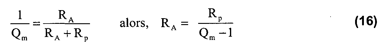
L'ensemble se comporte donc comme une inductance ou self de valeur L3 = RA.RB.CA, mise en série avec la résistance RA. Il possible d'établir une relation donnant R3 en fonction de RA avec R3 = R03 -RA. L'agencement des paramètres choisis permet de ne pas avoir à monter ce composant, la valeur en série de RA présentant quasiment la valeur requise pour assurer l'atténuation désirée, 1/Qm, comme mentionné aux équations (9) et (10). En effet, si :
The assembly thus behaves like an inductance or self of value L 3 = R A .R B .C A , put in series with the resistor R A. It is possible to establish a relation giving R 3 as a function of R A with R 3 = R 03 -R A. The arrangement of the chosen parameters makes it possible not to have to mount this component, the series value of R A having almost the required value to ensure the desired attenuation, 1 / Q m , as mentioned in equations (9) and (10). ). Indeed, if:
Avantageusement, il peut être défini un facteur de résonance global prenant comme valeur optimale, celle d'un filtre selon Butterworth, ce qui correspond à
Advantageously, it is possible to define an overall resonance factor taking as optimal value, that of a filter according to Butterworth, which corresponds to
En partant des équations précédentes, il peut être procédé à la sélection des valeurs des paramètres suivants: Starting from the preceding equations, the values of the following parameters can be selected:
La figure 4 illustre les courbes de modules de l'accélération pour un pilotage en courant avec ou sans filtrage du pic de résonance ainsi que le module de l'accélération pour un pilotage en tension dudit au moins un haut-parleur, le filtrage s'effectuant avec un dispositif de filtrage selon la forme de réalisation de l'invention illustrée aux figures 1 à 3. FIG. 4 illustrates the modulus curves of the acceleration for current control with or without resonance peak filtering as well as the acceleration module for voltage control of the at least one speaker, the filtering performing with a filtering device according to the embodiment of the invention illustrated in Figures 1 to 3.
La courbe de commande en courant sans filtrage est celle avec des rectangles, la courbe de commande en courant avec filtrage est avec des cercles et la courbe de commande en tension est celle avec des losanges. The uncontrolled current control curve is that with rectangles, the current control curve with filtering is with circles and the voltage control curve is that with lozenges.
La courbe intermédiaire avec rectangles est la courbe avec pilotage en courant et filtrage avec un dispositif de filtrage selon la première forme de réalisation et montre l'absence d'un pic de résonance contrairement à la courbe supérieure avec pilotage en courant sans filtrage. De plus, cette courbe intermédiaire présente une plage de module d'accélération sensiblement constante plus large que celle de la courbe inférieure qui est la courbe avec pilotage en tension avec des losanges. The intermediate curve with rectangles is the curve with current control and filtering with a filtering device according to the first embodiment and shows the absence of a resonance peak unlike the upper curve with current control without filtering. In addition, this intermediate curve has a substantially constant acceleration modulus range wider than that of the lower curve which is the curve with voltage control with diamonds.
Il s'avère que le module de l'accélération avec un pic de résonance ainsi filtré présente un comportement satisfaisant si l'on considère comme non pénalisant l'ajout de deux circuits actifs avec deux convertisseurs auxiliaires pour l'obtention d'une inductance virtuelle d'une valeur proche de L3 = 6 H. It turns out that the modulus of the acceleration with a resonance peak thus filtered has a satisfactory behavior if it is considered as not penalizing the addition of two active circuits with two auxiliary converters for obtaining a virtual inductor. a value close to L 3 = 6 H.
La figure 5 illustre les courbes de degrés d'angle en fonction des fréquences, le filtrage s'effectuant avec un dispositif de filtrage selon la forme de réalisation de l'invention montrée aux figures 1 à 3, ceci pour la phase haut-parleur ou HP définie par la courbe portant des rectangles et pour la phase V3./V1 définie par la courbe portant des cercles. FIG. 5 illustrates the angle degree curves as a function of the frequencies, the filtering taking place with a filtering device according to the embodiment of the invention shown in FIGS. 1 to 3, for the speaker phase or HP defined by the curve bearing rectangles and for phase V 3 ./V 1 defined by the curve bearing circles.
Les courbes de la figure 5 montrent que l'angle de déphasage reste dans une gamme de valeurs parfaitement admissibles sur le domaine fréquentiel considéré. The curves of FIG. 5 show that the phase shift angle remains in a range of perfectly acceptable values over the frequency domain considered.
Dans une application préférentielle de la présente invention, des valeurs modérées affectées aux capacités, de l'ordre du microfarad, permettent la mise en oeuvre de condensateurs MKP en polypropylène, condensateurs qui sont bien adaptés aux régimes transitoires. In a preferred application of the present invention, moderate capacitance values of the order of the microfarad permit the implementation of polypropylene MKP capacitors, which capacitors are well suited to transient conditions.
Un exemple non limitatif va être maintenant donné pour un haut-parleur présentant les caractéristiques suivantes Bl=2,675 Tm, Mm=3,67 g, fm=0,539 N/m, km,=5650 N/m, fréquence de résonance = 197 Hz, Re=3,65Ω, L=0,12 mH. A non-limiting example will now be given for a loudspeaker having the following characteristics B l = 2.675 Tm, M m = 3.67 g, f m = 0.539 N / m, k m , = 5650 N / m, frequency of resonance = 197 Hz, Re = 3.65Ω, L = 0.12 mH.
Pour un tel haut-parleur, il peut être sélectionné les valeurs suivantes pour les divers éléments du circuit selon la présente invention, R3= 0 Ω, C3=0,29 μF, Rp=3 kΩ,
et La reproduite de manière active avec RA= 400Ω, RB= 1200Ω, Ca=4,7μF, soit L3 équivalente à 2,28 H. For such a loudspeaker, the following values can be selected for the various elements of the circuit according to the present invention, R 3 = 0 Ω, C 3 = 0.29 μF, Rp = 3 kΩ, and actively reproduced with R A = 400Ω, R B = 1200Ω, C a = 4.7μF, or L 3 equivalent to 2.28H.
Dans ce qui a été précédemment décrit, il a été utilisé dans le circuit au moins un convertisseur non inverseur, ceci pour simplification des calculs. Ceci n'est pas limitatif et la présente invention peut cependant aussi s'appliquer pour un circuit comprenant un ou plusieurs convertisseurs inverseurs. In what has been previously described, at least one non-inverting converter has been used in the circuit, in order to simplify the calculations. This is not limiting and the present invention can however also apply for a circuit comprising one or more inverters.
Le marché de la reproduction audio, particulièrement de la reproduction de haut de gamme est directement concerné par les dispositifs de filtrage conformes à la présente invention. Les grandes marques, du type Boose®, Bang & Olufsen®, Harman Kardon®, B&W®, etc., pourraient trouver un intérêt certain pour la diffusion commerciale de tels dispositifs de filtrage.
The market for audio reproduction, particularly high-end reproduction, is directly concerned with the filtering devices according to the present invention. Major brands, such as Boose ® , Bang & Olufsen ® , Harman Kardon ® , B & W ® , etc., could be of interest for the commercial distribution of such filtering devices.