WO2015137145A1 - Image coding device and method, and image decoding device and method - Google Patents
Image coding device and method, and image decoding device and method Download PDFInfo
- Publication number
- WO2015137145A1 WO2015137145A1 PCT/JP2015/055741 JP2015055741W WO2015137145A1 WO 2015137145 A1 WO2015137145 A1 WO 2015137145A1 JP 2015055741 W JP2015055741 W JP 2015055741W WO 2015137145 A1 WO2015137145 A1 WO 2015137145A1
- Authority
- WO
- WIPO (PCT)
- Prior art keywords
- unit
- image
- quantization parameter
- difference signal
- signal
- Prior art date
Links
Images


Classifications
-
- H—ELECTRICITY
- H04—ELECTRIC COMMUNICATION TECHNIQUE
- H04N—PICTORIAL COMMUNICATION, e.g. TELEVISION
- H04N19/00—Methods or arrangements for coding, decoding, compressing or decompressing digital video signals
- H04N19/10—Methods or arrangements for coding, decoding, compressing or decompressing digital video signals using adaptive coding
- H04N19/102—Methods or arrangements for coding, decoding, compressing or decompressing digital video signals using adaptive coding characterised by the element, parameter or selection affected or controlled by the adaptive coding
- H04N19/124—Quantisation
-
- H—ELECTRICITY
- H04—ELECTRIC COMMUNICATION TECHNIQUE
- H04N—PICTORIAL COMMUNICATION, e.g. TELEVISION
- H04N19/00—Methods or arrangements for coding, decoding, compressing or decompressing digital video signals
- H04N19/10—Methods or arrangements for coding, decoding, compressing or decompressing digital video signals using adaptive coding
- H04N19/134—Methods or arrangements for coding, decoding, compressing or decompressing digital video signals using adaptive coding characterised by the element, parameter or criterion affecting or controlling the adaptive coding
- H04N19/146—Data rate or code amount at the encoder output
- H04N19/152—Data rate or code amount at the encoder output by measuring the fullness of the transmission buffer
-
- H—ELECTRICITY
- H04—ELECTRIC COMMUNICATION TECHNIQUE
- H04N—PICTORIAL COMMUNICATION, e.g. TELEVISION
- H04N19/00—Methods or arrangements for coding, decoding, compressing or decompressing digital video signals
- H04N19/10—Methods or arrangements for coding, decoding, compressing or decompressing digital video signals using adaptive coding
- H04N19/169—Methods or arrangements for coding, decoding, compressing or decompressing digital video signals using adaptive coding characterised by the coding unit, i.e. the structural portion or semantic portion of the video signal being the object or the subject of the adaptive coding
- H04N19/17—Methods or arrangements for coding, decoding, compressing or decompressing digital video signals using adaptive coding characterised by the coding unit, i.e. the structural portion or semantic portion of the video signal being the object or the subject of the adaptive coding the unit being an image region, e.g. an object
- H04N19/176—Methods or arrangements for coding, decoding, compressing or decompressing digital video signals using adaptive coding characterised by the coding unit, i.e. the structural portion or semantic portion of the video signal being the object or the subject of the adaptive coding the unit being an image region, e.g. an object the region being a block, e.g. a macroblock
-
- H—ELECTRICITY
- H04—ELECTRIC COMMUNICATION TECHNIQUE
- H04N—PICTORIAL COMMUNICATION, e.g. TELEVISION
- H04N19/00—Methods or arrangements for coding, decoding, compressing or decompressing digital video signals
- H04N19/10—Methods or arrangements for coding, decoding, compressing or decompressing digital video signals using adaptive coding
- H04N19/169—Methods or arrangements for coding, decoding, compressing or decompressing digital video signals using adaptive coding characterised by the coding unit, i.e. the structural portion or semantic portion of the video signal being the object or the subject of the adaptive coding
- H04N19/186—Methods or arrangements for coding, decoding, compressing or decompressing digital video signals using adaptive coding characterised by the coding unit, i.e. the structural portion or semantic portion of the video signal being the object or the subject of the adaptive coding the unit being a colour or a chrominance component
-
- H—ELECTRICITY
- H04—ELECTRIC COMMUNICATION TECHNIQUE
- H04N—PICTORIAL COMMUNICATION, e.g. TELEVISION
- H04N19/00—Methods or arrangements for coding, decoding, compressing or decompressing digital video signals
- H04N19/30—Methods or arrangements for coding, decoding, compressing or decompressing digital video signals using hierarchical techniques, e.g. scalability
-
- H—ELECTRICITY
- H04—ELECTRIC COMMUNICATION TECHNIQUE
- H04N—PICTORIAL COMMUNICATION, e.g. TELEVISION
- H04N19/00—Methods or arrangements for coding, decoding, compressing or decompressing digital video signals
- H04N19/46—Embedding additional information in the video signal during the compression process
- H04N19/463—Embedding additional information in the video signal during the compression process by compressing encoding parameters before transmission
-
- H—ELECTRICITY
- H04—ELECTRIC COMMUNICATION TECHNIQUE
- H04N—PICTORIAL COMMUNICATION, e.g. TELEVISION
- H04N19/00—Methods or arrangements for coding, decoding, compressing or decompressing digital video signals
- H04N19/70—Methods or arrangements for coding, decoding, compressing or decompressing digital video signals characterised by syntax aspects related to video coding, e.g. related to compression standards
Definitions
- the present disclosure relates to an image encoding apparatus and method, and an image decoding apparatus and method, and in particular, an image encoding apparatus and method, and an image decoding apparatus and method capable of controlling the code amount of a color difference signal in an image. About.
- Non-Patent Document 1 High Efficiency Video Coding
- JCTVC Joint Collaboration Team-Video Coding
- the color gamut according to BT.709 is used, but in UHD (4000 ⁇ 2000 pixels, 8000 ⁇ 4000 pixels), the color gamut according to BT.2020 is used. Is being considered. Furthermore, as a bit depth, 10 bits or 12 bits are being considered instead of 8 bits.
- JCTVC-L1003_v4 Joint Collaborative Team on Video Coding (JCT-VC) of ITU-T SG 16 WP 3 and ISO / IEC JTC 1 / SC 29 / WG 11 12th Meeting: Geneva, CH, 14-23 Jan. 2013
- the present disclosure has been made in view of such a situation, and can control the code amount of a color difference signal in an image.
- An image encoding device includes a color difference signal quantization determination unit that determines a quantization parameter of a color difference signal with high quantization accuracy compared to a quantization parameter of a luminance signal in an image, and the luminance signal Using a quantization parameter and a color difference signal quantization parameter determined by the color difference signal quantization determination unit, a quantization unit that quantizes the image, and an image quantized by the quantization unit, An encoding unit that generates an encoded stream.
- the chrominance signal quantization determination unit sets the quantization parameter of the chrominance signal so that when the quantization parameter of the chrominance signal is increased by 12, the quantization parameter of the chrominance signal is roughly twice as large as the quantization parameter of the luminance signal. Can be determined.
- the ⁇ QP C is calculated in units of coding units.
- ⁇ QP C The value of ⁇ QP C is 0 or 1.
- the color space is YCbCr, and the transmission unit can transmit ⁇ QP C having independent values for the Cb signal and the Cr signal.
- the quantization parameter for the luminance signal is QP Y
- the quantization parameter for the color difference signal is QP C
- the quantization parameter offset of the color difference signal is offset
- YtoC is the quantization parameter of the luminance signal and the quantization parameter of the color difference signal QP C is defined as Is calculated as
- the quantization parameter for the luminance signal is QP Y
- the quantization parameter for the color difference signal is QP C
- the quantization parameter offset of the color difference signal is offset
- YtoC is the quantization parameter of the luminance signal and the quantization parameter of the color difference signal
- the color space is YDzDx.
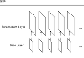
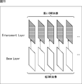
- the chrominance signal quantization determining unit performs quantization of the chrominance signal separately from the quantization parameter of the luminance signal in the enhancement layer image having the input of the wide gamut signal when performing the scalability coding processing based on the gamut scalability. Parameters can be determined.
- the color difference signal quantization parameter offset transmitted together with the encoded stream obtained by encoding the image in the enhancement layer is a negative value.
- the quantization parameter of the color difference signal determined by the color difference signal quantization determination unit is encoded stream Is transmitted with.
- an image encoding device determines a quantization parameter of a color difference signal with higher quantization accuracy than a quantization parameter of a luminance signal in an image, and the quantization of the luminance signal The image is quantized using the quantization parameter and the quantization parameter of the determined color difference signal, and the quantized image is encoded to generate an encoded stream.
- An image decoding device includes: a decoding unit that decodes an encoded stream to generate an image; and a quantization accuracy that is higher than a quantization parameter of a luminance signal in an image generated by the decoding unit
- a chrominance signal quantization determination unit that determines a quantization parameter of the chrominance signal in the decoding unit using the quantization parameter of the luminance signal and the quantization parameter of the chrominance signal determined by the chrominance signal quantization determination unit
- an inverse quantization unit that inversely quantizes the image generated by.
- the color-difference signal quantization determining unit when the quantization parameter of the color-difference signal is increased by 12, so that the quantization parameter of the color-difference signal is inversely quantized twice as compared with the quantization parameter of the luminance signal Can be determined.
- a receiver for the DerutaQP C is a parameter for the color difference signal can be further provided.
- the ⁇ QP C is calculated in units of coding units.
- ⁇ QP C The value of ⁇ QP C is 0 or 1.
- the color space is YCbCr, and the reception unit can receive ⁇ QP C having independent values for the Cb signal and the Cr signal.
- An image decoding method includes an image decoding device that generates an image by decoding an encoded stream, and has a color difference with high quantization accuracy compared to a quantization parameter of a luminance signal in the generated image.
- a quantization parameter of the signal is determined, and the generated image is inversely quantized using the quantization parameter of the luminance signal and the determined quantization parameter of the color difference signal.
- the quantization parameter of the color difference signal is determined with higher quantization accuracy than the quantization parameter of the luminance signal in the image. Then, the image is quantized using the quantization parameter of the luminance signal and the determined quantization parameter of the color difference signal, the quantized image is encoded, and an encoded stream is generated.
- an image is generated by decoding an encoded stream, and the quantization parameter of the color difference signal is determined with higher quantization accuracy than the quantization parameter of the luminance signal in the generated image. The Then, the generated image is inversely quantized using the quantization parameter of the luminance signal and the determined quantization parameter of the color difference signal.
- image encoding device and image decoding device may be independent image processing devices, or may be internal blocks constituting one image encoding device or image decoding device.
- an image can be encoded.
- it is possible to control the code amount of the color difference signal in the image.
- an image can be decoded.
- it is possible to control the code amount of the color difference signal in the image.
- FIG. 15 is a flowchart for explaining an example of a quantization parameter reconstruction process in FIG. 14; FIG.
- FIG. 1 It is a figure which shows the schematic structural example of the imaging device to which this indication is applied. It is a block diagram which shows an example of scalable encoding utilization. It is a block diagram which shows the other example of scalable encoding utilization. It is a block diagram which shows the further another example of scalable encoding utilization.
- 2 illustrates an example of a schematic configuration of a video set to which the present disclosure is applied. 2 illustrates an example of a schematic configuration of a video processor to which the present disclosure is applied. The other example of the schematic structure of the video processor to which this indication is applied is shown.
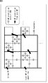
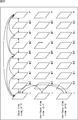
- FIG. 1 is a diagram for explaining Coding UNIT (CU), which is a coding unit in the HEVC scheme.
- CU is defined as a coding unit.
- the CU plays the same role as a macroblock in the AVC method. Specifically, the CU is divided into PUs or TUs.
- the size of the CU is a square represented by a power-of-two pixel that is variable for each sequence.
- the CU divides the LCU, which is the largest CU, into two in the horizontal direction and the vertical direction an arbitrary number of times so as not to be smaller than the SCU (Smallest Coding Unit) which is the smallest CU.
- SCU Smallest Coding Unit
- the LCU size is 128 and the SCU size is 8. Accordingly, the hierarchical depth (Depth) of the LCU is 0 to 4, and the hierarchical depth number is 5. That is, the number of divisions corresponding to the CU is one of 0 to 4.
- Non-Patent Document 1 Information specifying the LCU and SCU sizes is included in the SPS. Also, the number of divisions corresponding to the CU is specified by split_flag indicating whether or not to further divide each layer. Details of the CU are described in Non-Patent Document 1.
- TU size can be specified using split_transform_flag, similar to CU split_flag.
- the maximum number of TU divisions during inter prediction and intra prediction is specified by SPS as max_transform_hierarchy_depth_inter and max_transform_hierarchy_depth_intra, respectively.
- CTU Coding Tree Unit
- CTB Coding Tree Block
- LCU base level
- a CU constituting a CTU is a unit including CB (Coding Block) and a parameter for processing on the CU base (level).
- Mode selection By the way, in the AVC and HEVC encoding schemes, selection of an appropriate prediction mode is important to achieve higher encoding efficiency.
- JM Job Model
- JM JM
- High Complexity Mode Low Complexity Mode.
- a cost function value for each prediction mode Mode is calculated, and a prediction mode that minimizes the cost function value is selected as the optimum mode for the block or macroblock.
- ⁇ is the entire set of candidate modes for encoding the block or macroblock
- D is the difference energy between the decoded image and the input image when encoded in the prediction mode.
- ⁇ is a Lagrange undetermined multiplier given as a function of the quantization parameter.
- R is the total code amount when encoding is performed in this mode, including orthogonal transform coefficients.
- D is the difference energy between the predicted image and the input image, unlike the case of High Complexity Mode.
- QP2Quant QP
- HeaderBit is a code amount related to information belonging to Header, such as a motion vector and mode, which does not include an orthogonal transform coefficient.
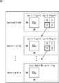
- “Org” shown in FIG. 2 is a test image of video conference content of 1280 ⁇ 720 pixels.
- rate control such as MPEG-2 Test Model 5
- quantization control within a picture is performed for each macroblock by “activity” based on pixel dispersion values.
- diff_cu_qp_delta_depth is set in PPS (Picture Parameter Set) and the quantization parameter can be transmitted with a granularity of up to coding unit for the LCU size.
- the coding unit of that size is called CUQG (coding unit / quantization group).
- the quantization parameter is transmitted in the first transform unit where CBF (coded block flag, which has a non-zero orthogonal transform coefficient when its value is 1) is 1, in CUQG.
- the quantization parameter for each coding unit is calculated as in the following equation (3).
- ⁇ QP is a difference value from the predicted value transmitted for each CUQG.
- the predicted value QP PRED of the quantization parameter is calculated as in the following equation (4).
- qP Y_A and qP Y_B are quantization parameters for CUs located on the upper and left sides of the CU. However, when the CUs located at the top and left are outside the LCU, the value of the quantization parameter used in the immediately preceding encoding or decoding process is used as the value of qP Y_A or qP Y_B .
- FIG. 3 shows a diagram relating to this processing.
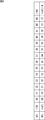
- the default relationship between the luminance signal and the color difference signal is determined as shown in FIG. 4 or FIG. 5, and the user can adjust this by choma_qp_offset.
- a black circle indicates AVC
- a triangle indicates HEVC.
- choma_qp_offset when only choma_qp_offset exists, this is applied to both Cb / Cr signals, and when choma_qp_offset and 2nd_ choma_qp_offset exist, they are applied to Cb and Cr, respectively.
- cb_qp_offset and cr_qp_offset are applied to Cb and Cr, respectively.
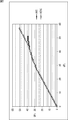
- the quantization parameter for the luminance signal can take 51 as the maximum value, but even if adjustment by chroma_qp_offset is performed, the quantization parameter for the color difference signal is limited to 39, and the restriction by CPB is severe. Therefore, even when it is desired to reduce the number of bits, this condition becomes a bottleneck, and it may be difficult to perform desired rate control.
- the quantization parameter for the color difference signal can also take 51 as the maximum value.
- the HD (1920 ⁇ 1080 pixels) uses a color gamut according to BT.709 as shown in FIG. 6, while the UHD 4000 (4000 ⁇ 2000 pixels, 8000 ⁇ 4000 pixels) uses BT.
- the use of a color gamut according to 2020 is being studied, and 10 bits or 12 bits are being considered as the bit depth instead of 8 bits.
- the color difference signal is quantized with higher accuracy than the luminance signal, thereby improving the rate controllability of the color difference signal.
- the color difference signal has higher accuracy than the luminance signal.
- the quantization is performed with a quantization scale that is twice as coarse.
- the quantization parameter QP C for the color difference signal is expressed by the following equation (5) from the quantization parameter QP Y for the luminance signal, the offset, and the relationship YtoC shown in FIG. ).
- ⁇ QP C is further transmitted in units of Coding Units, and is calculated as in the following equation (6).
- a deltaQP is transmitted to a Coring Unit of a predetermined size, and a quantization parameter for the CodingUnit is calculated based on this and a predicted quantization parameter value predQP calculated for each CodingUnit. It is assumed that C is transmitted simultaneously with this deltaQP. The value is assumed to be 0 or 1.
- n is an integer of 2 or more and the following equation (7) can be used to take values of 0, 1,.
- n may be transmitted in SPS (Sequence Parameter Set) in the output image compression information. Note that the values may be different values for the Cb component and the Cr component.
- the value of ⁇ QP C may be a value other than 0 and 1. Accordingly, in the present technology, it is possible to set the quantization parameter value of the color difference signal independently of the luminance signal for each Colling Unitg.
- the method when the method according to the present technology is realized in the color gamut scalability, the method may be applied to an enhancement layer which receives a wide color gamut image signal. At this time, on the encoding side, it is possible to improve the encoding efficiency by setting ChromaQpOffset in the enhancement layer to a negative value.
- FIG. 8 is a block diagram illustrating a configuration example of an embodiment of an encoding device to which the present disclosure is applied.
- the 8 is configured by a setting unit 11, an encoding unit 12, and a transmission unit 13, and encodes an image by a method according to the HEVC method.
- the setting unit 11 of the encoding device 10 sets VUI (Video Usability Information), SEI (Supplemental Enhancement Information), and the like.
- the setting unit 11 supplies the set parameter set such as SPS, PPS, VUI, and SEI to the encoding unit 12.
- the frame unit image is input to the encoding unit 12.
- the encoding unit 12 refers to the parameter set supplied from the setting unit 11 and encodes the input image by a method according to the HEVC method.
- the encoding unit 12 generates an encoded stream from encoded data obtained as a result of encoding and a parameter set, and supplies the encoded stream to the transmission unit 13.
- the transmission unit 13 transmits the encoded stream supplied from the encoding unit 12 to a decoding device to be described later.
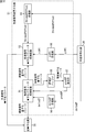
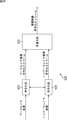
- FIG. 9 is a block diagram illustrating a configuration example of the encoding unit 12 of FIG.
- the encoding unit 12 includes a deblocking filter 41, an adaptive offset filter 42, an adaptive loop filter 43, a frame memory 44, a switch 45, an intra prediction unit 46, a motion prediction / compensation unit 47, a predicted image selection unit 48, a rate control. Part 49. Furthermore, the encoding unit 12 includes a color difference signal quantization unit 50 and a color difference signal inverse quantization unit 51.
- the A / D conversion unit 31 of the encoding unit 12 performs A / D conversion on the frame-by-frame image input as an encoding target.
- the A / D conversion unit 31 outputs an image, which is a digital signal after conversion, to the screen rearrangement buffer 32 for storage.
- the screen rearrangement buffer 32 rearranges the stored frame-by-frame images in the order for encoding according to the GOP structure.
- the screen rearrangement buffer 32 outputs the rearranged image to the calculation unit 33, the intra prediction unit 46, and the motion prediction / compensation unit 47.
- the calculation unit 33 performs encoding by subtracting the prediction image supplied from the prediction image selection unit 48 from the image supplied from the screen rearrangement buffer 32.
- the calculation unit 33 outputs the image obtained as a result to the orthogonal transform unit 34 as residual information (difference).
- the calculation unit 33 outputs the image read from the screen rearrangement buffer 32 as it is to the orthogonal transform unit 34 as residual information.
- the orthogonal transform unit 34 performs orthogonal transform processing on the residual information from the calculation unit 33 in units of TUs.
- the orthogonal transformation unit 34 supplies the orthogonal transformation processing result after the orthogonal transformation processing to the quantization unit 35.
- TU sizes include 4x4 pixels, 8x8 pixels, 16x16 pixels, and 32x32 pixels.
- orthogonal transform there is, for example, DCT (Discrete Cosine Transform) (discrete cosine transform).
- the DCT orthogonal transformation matrix when the TU is 4 ⁇ 4 pixels, 8 ⁇ 8 pixels, and 16 ⁇ 16 pixels is 1/8, the DCT orthogonal transformation matrix when the TU is 32 ⁇ 32 pixels, respectively. Obtained by decimation to 1 / 4,1 / 2. Therefore, the orthogonal transform unit 34 may be provided with a common calculation unit for all TU sizes, and does not need to be provided for each TU size.
- DST Discrete Sine Transform
- the orthogonal transform method is used. Since DST is used as the coding efficiency, the coding efficiency is improved.
- the quantization unit 35 quantizes the orthogonal transformation processing result supplied from the orthogonal transformation unit 34 using the luminance signal quantization parameter and the color difference signal quantization parameter from the color difference signal quantization unit 50.
- the quantization unit 35 supplies the quantized value obtained as a result of the quantization to the lossless encoding unit 36.
- the lossless encoding unit 36 acquires deltaQP, ⁇ QPC, and ChromaQPOffset.
- the lossless encoding unit 36 acquires information indicating the optimal intra prediction mode (hereinafter referred to as intra prediction mode information) from the intra prediction unit 46. Further, the lossless encoding unit 36 acquires information indicating the optimal inter prediction mode (hereinafter referred to as inter prediction mode information), a motion vector, information specifying a reference image, and the like from the motion prediction / compensation unit 47.
- the lossless encoding unit 36 acquires offset filter information regarding the offset filter from the adaptive offset filter 42 and acquires filter coefficients from the adaptive loop filter 43.
- the lossless encoding unit 36 performs variable length coding (for example, CAVLC (Context-Adaptive Variable Length Coding)) and arithmetic coding (for example, CABAC (Context) on the quantization value supplied from the quantization unit 35. -Adaptive Binary Arithmetic Coding) etc.).
- variable length coding for example, CAVLC (Context-Adaptive Variable Length Coding)
- CABAC Context
- CABAC Context-Adaptive Binary Arithmetic Coding
- the lossless encoding unit 36 encodes deltaQP, ⁇ QPC, and ChromaQPOffset, intra prediction mode information, or inter prediction mode information, a motion vector, information specifying a reference image, offset filter information, and a filter coefficient. Lossless encoding is performed as the encoding information regarding.
- the lossless encoding unit 36 supplies the encoded information and the quantized value, which are losslessly encoded, to the accumulation buffer 37 as encoded data, and accumulates them. Note that deltaQP, ⁇ QPC, and ChromaQPOffset are losslessly encoded and supplied to the color difference signal inverse quantization unit 51.
- the losslessly encoded information may be header information (for example, a slice header) of a losslessly encoded quantization value.
- the accumulation buffer 37 temporarily stores the encoded data supplied from the lossless encoding unit 36.
- the accumulation buffer 37 supplies the stored encoded data to the transmission unit 13 as an encoded stream together with the parameter set supplied from the setting unit 11 in FIG.
- the quantized value output from the quantizing unit 35 is also input to the inverse quantizing unit 38.
- the inverse quantization unit 38 inversely quantizes the quantization value using the luminance signal quantization parameter and the color difference signal quantization parameter from the color difference signal inverse quantization unit 51.
- the inverse quantization unit 38 supplies the orthogonal transform processing result obtained as a result of the dequantization to the inverse orthogonal transform unit 39.
- the inverse orthogonal transform unit 39 performs an inverse orthogonal transform process on the orthogonal transform process result supplied from the inverse quantization unit 38 in units of TUs.
- inverse orthogonal transform for example, there are IDCT (Inverse Discrete Cosine Transform) and IDST (Inverse Discrete Sine Transform).
- IDCT Inverse Discrete Cosine Transform
- IDST Inverse Discrete Sine Transform
- the addition unit 40 adds the residual information supplied from the inverse orthogonal transform unit 39 and the prediction image supplied from the prediction image selection unit 48, and performs decoding.
- the adder 40 supplies the decoded image to the deblock filter 41 and the frame memory 44.
- the deblocking filter 41 performs an adaptive deblocking filter process for removing block distortion on the decoded image supplied from the adding unit 40, and supplies the resulting image to the adaptive offset filter.
- the adaptive offset filter 42 performs an adaptive offset filter (SAO (Sample adaptive offset)) process that mainly removes ringing on the image after the adaptive deblock filter process by the deblock filter 41.
- SAO Sample adaptive offset
- the adaptive offset filter 42 determines the type of adaptive offset filter processing for each LCU (Largest Coding Unit) which is the maximum coding unit, and obtains an offset used in the adaptive offset filter processing.
- the adaptive offset filter 42 performs the determined type of adaptive offset filter processing on the image after the adaptive deblocking filter processing, using the obtained offset.
- the adaptive offset filter 42 supplies the image after the adaptive offset filter processing to the adaptive loop filter 43. Further, the adaptive offset filter 42 supplies information indicating the type and offset of the adaptive offset filter processing performed to the lossless encoding unit 36 as offset filter information.
- the adaptive loop filter 43 is configured by, for example, a two-dimensional Wiener filter.
- the adaptive loop filter 43 performs an adaptive loop filter (ALF (Adaptive Loop Filter)) process for each LCU, for example, on the image after the adaptive offset filter process supplied from the adaptive offset filter 42.
- ALF Adaptive Loop Filter
- the adaptive loop filter 43 is configured so that the residual of the original image that is the image output from the screen rearrangement buffer 32 and the image after the adaptive loop filter processing is minimized for each LCU. A filter coefficient used in the processing is calculated. Then, the adaptive loop filter 43 performs adaptive loop filter processing for each LCU using the calculated filter coefficient on the image after the adaptive offset filter processing.
- the adaptive loop filter 43 supplies the image after the adaptive loop filter processing to the frame memory 44.
- the adaptive loop filter 43 supplies the filter coefficient used for the adaptive loop filter process to the lossless encoding unit 36.
- the adaptive loop filter processing is performed for each LCU, but the processing unit of the adaptive loop filter processing is not limited to the LCU. However, the processing can be efficiently performed by combining the processing units of the adaptive offset filter 42 and the adaptive loop filter 43.
- the frame memory 44 stores the image supplied from the adaptive loop filter 43 and the image supplied from the adder 40.
- An image adjacent to a PU (Prediction Unit) among the images not subjected to the filter processing accumulated in the frame memory 44 is supplied to the intra prediction unit 46 via the switch 45 as a peripheral image.
- the filtered image stored in the frame memory 44 is output to the motion prediction / compensation unit 47 via the switch 45 as a reference image.
- the intra prediction unit 46 performs intra prediction processing for all candidate intra prediction modes using peripheral images read from the frame memory 44 via the switch 45 in units of PUs.
- the intra prediction unit 46 also calculates the cost function value for all candidate intra prediction modes based on the image read from the screen rearrangement buffer 32 and the prediction image generated as a result of the intra prediction process. (Details will be described later). Then, the intra prediction unit 46 determines the intra prediction mode that minimizes the cost function value as the optimal intra prediction mode.
- the intra prediction unit 46 supplies the predicted image generated in the optimal intra prediction mode and the corresponding cost function value to the predicted image selection unit 48.
- the intra prediction unit 46 supplies the intra prediction mode information to the lossless encoding unit 36 when the prediction image selection unit 48 is notified of selection of a prediction image generated in the optimal intra prediction mode.
- the intra prediction mode is a mode that represents the PU size, the prediction direction, and the like.
- the motion prediction / compensation unit 47 performs motion prediction / compensation processing for all candidate inter prediction modes in PU units. Specifically, the motion prediction / compensation unit 47 selects all candidate inter prediction modes based on the image supplied from the screen rearrangement buffer 32 and the reference image read from the frame memory 44 via the switch 45. Are detected in units of PUs. Then, the motion prediction / compensation unit 47 performs compensation processing on the reference image for each PU based on the motion vector, and generates a predicted image.
- the motion prediction / compensation unit 47 calculates the cost function value for all candidate inter prediction modes based on the image and the predicted image supplied from the screen rearrangement buffer 32, and the cost function value. Is determined to be the optimal inter prediction mode. Then, the motion prediction / compensation unit 47 supplies the cost function value of the optimal inter prediction mode and the corresponding prediction image to the prediction image selection unit 48. Further, the motion prediction / compensation unit 47 outputs the raw / inter prediction mode information, the corresponding motion vector, information for specifying the reference image, and the like from the predicted image selection unit 48 to the lossless encoding unit 36 in the optimal inter prediction mode.
- the inter prediction mode is a mode that represents the size of the PU and the like.
- the predicted image selection unit 48 Based on the cost function values supplied from the intra prediction unit 46 and the motion prediction / compensation unit 47, the predicted image selection unit 48 has a smaller corresponding cost function value of the optimal intra prediction mode and the optimal inter prediction mode. Are determined as the optimum prediction mode. Then, the predicted image selection unit 48 supplies the predicted image in the optimal prediction mode to the calculation unit 33 and the addition unit 40. Further, the predicted image selection unit 48 notifies the intra prediction unit 46 or the motion prediction / compensation unit 47 of selection of the predicted image in the optimal prediction mode.
- the rate control unit 49 controls the quantization operation rate of the quantization unit 35 based on the encoded data stored in the storage buffer 37 so that overflow or underflow does not occur. Also, the rate control unit 49 supplies the luminance signal quantization parameter, the color difference signal quantization parameter, and ChromaQPOffset to the color difference signal quantization unit 50.
- the color difference signal quantization unit 50 uses the luminance signal quantization parameter, the color difference signal quantization parameter, and the ChromaQPOffset from the rate control unit 49 to determine the luminance signal quantization parameter and the color difference signal quantization parameter for each CU.
- the color difference signal quantization unit 50 supplies the determined luminance signal quantization parameter and color difference signal quantization parameter to the quantization unit 35.
- the color difference signal quantization unit 50 calculates the predicted quantization parameter predQP from the quantization parameter of the adjacent CU.
- the color difference signal quantization unit 50, the determined luminance signal quantization parameters and a color difference signal quantization parameter, and the calculated predicted quantization parameter PredQP calculates DeltaQP, the ⁇ QP C.
- the color difference signal quantization unit 50 supplies the calculated DeltaQP, and DerutaQP C, and ChromaQPOffset, supplied to the lossless encoding unit 36.
- Chrominance signal inverse quantization unit 51 receives DeltaQP, and DerutaQP C, and ChromaQPOffset from the lossless encoding section 36.
- the color difference signal inverse quantization unit 51 calculates a predicted quantization parameter predQP from the quantization parameters of adjacent CUs.
- the color difference signal inverse quantization unit 51 reconstructs the luminance signal quantization parameter from the deltaQP and the predQP, and determines the luminance signal quantization parameter. Then, the color difference signal inverse quantization unit 51 supplies the determined luminance signal quantization parameter to the inverse quantization unit 38.
- the color difference signal inverse quantization unit 51 reconstructs the color difference signal quantization parameter from the reconstructed luminance signal quantization parameter, ⁇ QP C and ChromaQPOffset, and determines the color difference signal quantization parameter.
- the color difference signal inverse quantization unit 51 supplies the determined color difference signal quantization parameter to the inverse quantization unit 38.
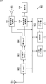
- FIG. 10 is a block diagram illustrating a configuration example of the color difference signal quantization unit 50 of FIG.
- a luminance signal quantization parameter buffer 81 includes a luminance signal quantization parameter buffer 81, a color difference signal quantization parameter buffer 82, a ChromaQPOffset buffer 83, a deitaQP calculation unit 84, an adjacent QP buffer 85, a ⁇ QPC calculation unit 86, and a predQP calculation unit. 87 is included.
- the luminance signal quantization parameter, the color difference signal quantization parameter, and the ChromaQPOffset are supplied from the rate control unit 49 to the luminance signal quantization parameter buffer 81, the color difference signal quantization parameter buffer 82, and the ChromaQPOffset buffer 83, respectively.
- the luminance signal quantization parameter buffer 81 accumulates the luminance signal quantization parameter from the rate control unit 49 and determines it as the luminance signal quantization parameter for the CU.
- the luminance signal quantization parameter buffer 81 supplies the determined luminance signal quantization parameter to the quantization unit 35, the deltaQP calculation unit 84, the adjacent QP buffer 85, and the ⁇ QPC calculation unit 86.
- the color difference signal quantization parameter buffer 82 accumulates the color difference signal quantization parameters from the rate control unit 49 and determines the color difference signal quantization parameters for the CU.
- the color difference signal quantization parameter buffer 82 supplies the determined color difference signal quantization parameter to the quantization unit 35 and the ⁇ QPC calculation unit 86.
- the ChromaQPOffset buffer 83 accumulates the ChromaQPOffset from the rate control unit 49 and supplies it to the ⁇ QPC calculation unit 86 and the lossless encoding unit 36.
- the deltaQP calculation unit 84 calculates the deltaQP from the luminance signal quantization parameter buffer 81 using the luminance signal quantization parameter related to the CU and the predQP from the predQP calculation unit 87.
- the deltaQP calculation unit 84 supplies the calculated deltaQP to the lossless encoding unit 36.
- the adjacent QP buffer 85 accumulates the luminance signal quantization parameter from the luminance signal quantization parameter buffer 81, and supplies the luminance signal quantization parameter to the predQP calculation unit 87 as a luminance quantization parameter related to the adjacent CU (hereinafter referred to as an adjacent quantization parameter).
- the ⁇ QPC calculation unit 86 calculates ⁇ QPC using the luminance signal quantization parameter from the luminance signal quantization parameter buffer 81, the color difference signal quantization parameter from the color difference signal quantization parameter buffer 82, and ChromaQPOffset from the ChromaQPOffset buffer 83. .
- the ⁇ QPC calculation unit 86 supplies the calculated ⁇ QPC to the lossless encoding unit 36.
- the predQP calculation unit 87 uses the adjacent quantization parameter from the adjacent QP buffer 85 to calculate predQP by a method defined in HEVC or the like.
- the predQP calculation unit 87 supplies the calculated predQP to the deltaQP calculation unit 84.
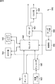
- FIG. 11 is a block diagram illustrating a configuration example of the color difference signal inverse quantization unit 51 in FIG. 9.
- the color difference signal inverse quantization unit 51 in FIG. 11 includes a luminance signal quantization parameter reconstruction unit 91, a color difference signal quantization parameter reconstruction unit 92, a ChromaQPOffset reception unit 93, a deltaQP reception unit 94, an adjacent QP buffer 95, and a ⁇ QPC reception unit. 96, and a predQP calculation unit 97.
- the deltaQP, ⁇ QPC, and ChromaQPOffset are supplied from the lossless encoding unit 36 to the deltaQP reception unit 94, the ⁇ QPC reception unit 96, and the ChromaQPOffset reception unit 93, respectively.
- the luminance signal quantization parameter reconstruction unit 91 reconstructs the luminance signal quantization parameter using the deltaQP from the deltaQP reception unit 94 and the predQP from the predQP calculation unit 97.
- the luminance signal quantization parameter reconstruction unit 91 supplies the reconstructed luminance signal quantization parameter to the inverse quantization unit 38, the color difference signal quantization parameter reconstruction unit 92, and the adjacent QP buffer 95.
- the color difference signal quantization parameter reconstruction unit 92 uses the ⁇ QPC from the ⁇ QPC reception unit 96, the ChromaQPOffset from the ChromaQPOffset reception unit 93, and the luminance signal quantization parameter from the luminance signal quantization parameter reconstruction unit 91 to generate a color difference signal. Reconstruct the quantization parameter.
- the color difference signal quantization parameter reconstruction unit 92 supplies the reconstructed color difference signal quantization parameter to the inverse quantization unit 38.
- the ChromaQPOffset reception unit 93 receives the ChromaQPOffset from the lossless encoding unit 36 and supplies it to the color difference signal quantization parameter reconstruction unit 92.
- the deltaQP receiver 94 receives the deltaQP from the lossless encoder 36 and supplies it to the luminance signal quantization parameter reconstructor 91.
- the adjacent QP buffer 95 accumulates the luminance signal quantization parameter from the luminance signal quantization parameter reconstruction unit 91 and supplies it to the predQP calculation unit 97 as an adjacent quantization parameter.
- the ⁇ QPC receiving unit 96 receives ⁇ QPC from the lossless encoding unit 36 and supplies it to the color difference signal quantization parameter reconstruction unit 92.
- the predQP calculation unit 97 uses the adjacent quantization parameter from the adjacent QP buffer 95 to calculate predQP by a method defined in HEVC or the like.
- the predQP calculation unit 97 supplies the calculated predQP to the luminance signal quantization parameter reconstruction unit 91.
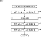
- FIG. 12 is a flowchart illustrating the stream generation processing of the encoding device 10 of FIG.
- step S11 of FIG. 12 the setting unit 11 of the encoding device 10 sets a parameter set.
- the setting unit 11 supplies the set parameter set to the encoding unit 12.
- step S12 the encoding unit 12 performs an encoding process in which an image in units of frames input from the outside is encoded by a method according to the HEVC method. Details of the encoding process will be described with reference to FIGS. 13 and 14 to be described later.
- step S13 the accumulation buffer 37 (FIG. 9) of the encoding unit 12 generates an encoded stream from the parameter set supplied from the setting unit 11 and the stored encoded data, and supplies the encoded stream to the transmission unit 13.
- step S14 the transmission unit 13 transmits the encoded stream supplied from the setting unit 11 to the decoding device 110 described later, and ends the process.
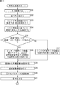
- FIGS. 13 and 14 are flowcharts illustrating details of the encoding process in step S12 of FIG.
- step S31 of FIG. 13 the A / D conversion unit 31 (FIG. 9) of the encoding unit 12 performs A / D conversion on the frame unit image input as the encoding target.
- the A / D conversion unit 31 outputs an image, which is a digital signal after conversion, to the screen rearrangement buffer 32 for storage.
- step S32 the screen rearrangement buffer 32 rearranges the stored frame images in the display order in the order for encoding according to the GOP structure.
- the screen rearrangement buffer 32 supplies the rearranged frame-unit images to the calculation unit 33, the intra prediction unit 46, and the motion prediction / compensation unit 47.
- step S33 the intra prediction unit 46 performs intra prediction processing in all intra prediction modes that are candidates in PU units. Further, the intra prediction unit 46 calculates cost function values for all candidate intra prediction modes based on the image read from the screen rearrangement buffer 32 and the predicted image generated as a result of the intra prediction process. Is calculated. Then, the intra prediction unit 46 determines the intra prediction mode that minimizes the cost function value as the optimal intra prediction mode. The intra prediction unit 46 supplies the predicted image generated in the optimal intra prediction mode and the corresponding cost function value to the predicted image selection unit 48.
- the motion prediction / compensation unit 47 performs motion prediction / compensation processing for all candidate inter prediction modes in PU units.
- the motion prediction / compensation unit 47 calculates cost function values for all candidate inter prediction modes based on the images supplied from the screen rearrangement buffer 32 and the predicted images, and the cost function values are calculated.
- the minimum inter prediction mode is determined as the optimal inter prediction mode.
- the motion prediction / compensation unit 47 supplies the cost function value of the optimal inter prediction mode and the corresponding prediction image to the prediction image selection unit 48.
- step S ⁇ b> 34 the predicted image selection unit 48 selects one of the optimal intra prediction mode and the optimal inter prediction mode based on the cost function values supplied from the intra prediction unit 46 and the motion prediction / compensation unit 47 by the process of step S ⁇ b> 33. The one with the smallest cost function value is determined as the optimum prediction mode. Then, the predicted image selection unit 48 supplies the predicted image in the optimal prediction mode to the calculation unit 33 and the addition unit 40.
- step S35 the predicted image selection unit 48 determines whether or not the optimal prediction mode is the optimal inter prediction mode.
- the predicted image selection unit 48 notifies the motion prediction / compensation unit 47 of the selection of the predicted image generated in the optimal inter prediction mode.
- step S36 the motion prediction / compensation unit 47 supplies the inter prediction mode information, the motion vector, and information specifying the reference image to the lossless encoding unit 36, and the process proceeds to step S38.
- step S35 when it is determined in step S35 that the optimal prediction mode is not the optimal inter prediction mode, that is, when the optimal prediction mode is the optimal intra prediction mode, the predicted image selection unit 48 performs the prediction generated in the optimal intra prediction mode.
- the intra prediction unit 46 is notified of the image selection.
- step S37 the intra prediction unit 46 supplies the intra prediction mode information to the lossless encoding unit 36, and the process proceeds to step S38.
- step S38 the calculation unit 33 performs encoding by subtracting the prediction image supplied from the prediction image selection unit 48 from the image supplied from the screen rearrangement buffer 32.
- the computing unit 33 outputs the resulting image to the orthogonal transform unit 34 as residual information.
- step S39 the orthogonal transform unit 34 performs orthogonal transform processing on the residual information in units of TUs.
- the orthogonal transformation unit 34 supplies the orthogonal transformation processing result after the orthogonal transformation processing to the quantization unit 35.
- step S40 the color difference signal quantization unit 50 performs a quantization parameter determination process. Details of the quantization parameter determination processing will be described with reference to FIG.
- step S40 the determined luminance signal and color difference signal and their respective quantization parameters are supplied to the quantization unit 35. Further, the calculated deltaQP, ⁇ QPC, and ChromaQPOffset are supplied to the lossless encoding unit 36.
- step S41 the quantization unit 35 quantizes the orthogonal transformation processing result supplied from the orthogonal transformation unit 34 using the luminance signal quantization parameter and the color difference signal quantization parameter from the color difference signal quantization unit 50.
- the quantization unit 35 supplies the quantization value obtained as a result of the quantization to the lossless encoding unit 36 and the inverse quantization unit 38.
- the lossless encoding unit 36 supplies the deltaQP, ⁇ QPC, and ChromaQPOffset from the quantization unit 35 to the color difference signal inverse quantization unit 51.
- step S42 of FIG. 14 the color difference signal inverse quantization unit 51 performs a quantization parameter reconstruction process. Details of the quantization parameter reconstruction processing will be described with reference to FIG.
- step S42 the reconstructed luminance signal and color difference signal, and the respective quantization parameters are supplied to the inverse quantization unit 38.
- step S ⁇ b> 43 the inverse quantization unit 38 uses the luminance parameter quantization parameter and the color difference signal quantization parameter from the color difference signal inverse quantization unit 51 to inverse the quantization value from the quantization unit 35. Perform quantization.
- the inverse quantization unit 38 supplies the orthogonal transform processing result obtained as a result of the dequantization to the inverse orthogonal transform unit 39.
- step S44 the inverse orthogonal transform unit 39 performs an inverse orthogonal transform process on the orthogonal transform process result supplied from the inverse quantization unit 38 in units of TUs.
- the inverse orthogonal transform unit 39 supplies residual information obtained as a result of the inverse orthogonal transform process to the addition unit 40.
- step S45 the addition unit 40 adds the residual information supplied from the inverse orthogonal transform unit 39 and the prediction image supplied from the prediction image selection unit 48, and performs decoding.
- the adder 40 supplies the decoded image to the deblock filter 41 and the frame memory 44.
- step S46 the deblocking filter 41 performs a deblocking filtering process on the decoded image supplied from the adding unit 40.
- the deblocking filter 41 supplies the resulting image to the adaptive offset filter 42.
- step S47 the adaptive offset filter 42 performs an adaptive offset filter process on the image supplied from the deblocking filter 41 for each LCU.
- the adaptive offset filter 42 supplies the resulting image to the adaptive loop filter 43. Further, the adaptive offset filter 42 supplies the offset filter information to the lossless encoding unit 36 for each LCU.
- step S48 the adaptive loop filter 43 performs an adaptive loop filter process for each LCU on the image supplied from the adaptive offset filter 42.
- the adaptive loop filter 43 supplies the resulting image to the frame memory 44.
- the adaptive loop filter 43 also supplies the filter coefficient used in the adaptive loop filter process to the lossless encoding unit 36.
- step S49 the frame memory 44 stores the image supplied from the adaptive loop filter 43 and the image supplied from the adder 40.
- An image adjacent to the PU among the images not subjected to the filter processing accumulated in the frame memory 44 is supplied to the intra prediction unit 46 via the switch 45 as a peripheral image.
- the filtered image stored in the frame memory 44 is output to the motion prediction / compensation unit 47 via the switch 45 as a reference image.
- step S50 the lossless encoding unit 36 obtains intra prediction mode information, inter prediction mode information, information specifying a motion vector and a reference image, deltaQP, ⁇ QPC, and ChromaQPOffset, offset filter information, and filter coefficients. Lossless encoding is performed as encoded information.
- step S51 the lossless encoding unit 36 performs lossless encoding on the quantization value supplied from the quantization unit 35. Then, the lossless encoding unit 36 generates encoded data from the encoded information that has been losslessly encoded in the process of step S 50 and the quantized value that has been losslessly encoded, and supplies the encoded data to the accumulation buffer 37.
- step S52 the accumulation buffer 37 temporarily accumulates the encoded data supplied from the lossless encoding unit 36.
- step S53 the rate control unit 49 controls the quantization operation rate of the quantization unit 35 based on the encoded data stored in the storage buffer 37 so that overflow or underflow does not occur. Also, the rate control unit 49 supplies the luminance signal quantization parameter, the color difference signal quantization parameter, and ChromaQPOffset to the color difference signal quantization unit 50. And a process returns to step S12 of FIG. 12, and progresses to step S13.
- the intra prediction process and the motion prediction / compensation process are always performed for the sake of simplicity, but in actuality, either one of them depends on the picture type or the like. Sometimes only.
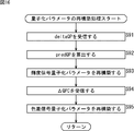
- FIG. 15 is a flowchart illustrating the quantization parameter determination process in step S40 of FIG.
- the luminance signal quantization parameter, the color difference signal quantization parameter, and the ChromaQPOffset are supplied from the rate control unit 49 to the luminance signal quantization parameter buffer 81, the color difference signal quantization parameter buffer 82, and the ChromaQPOffset buffer 83, respectively, and stored.
- the luminance signal quantization parameter buffer 81 determines, for example, the luminance signal quantization parameter from the rate control unit 49 as the luminance signal quantization parameter of the CU.
- the luminance signal quantization parameter buffer 81 supplies the determined luminance signal quantization parameter to the quantization unit 35, the deltaQP calculation unit 84, the adjacent QP buffer 85, and the ⁇ QPC calculation unit 86.
- the color difference signal quantization parameter buffer 82 determines, for example, the color difference signal quantization parameter from the rate control unit 49 as the color difference signal quantization parameter of the CU.
- the color difference signal quantization parameter buffer 82 supplies the determined color difference signal quantization parameter to the quantization unit 35 and the ⁇ QPC calculation unit 86.
- the adjacent QP buffer 85 accumulates the luminance signal quantization parameter from the luminance signal quantization parameter buffer 81, and supplies the luminance signal quantization parameter to the predQP calculation unit 87 as a luminance quantization parameter related to the adjacent CU (hereinafter referred to as an adjacent quantization parameter).
- the predQP calculation unit 87 uses the adjacent quantization parameter from the adjacent QP buffer 85 to calculate predQP by a method defined in HEVC or the like.
- the predQP calculation unit 87 supplies the calculated predQP to the deltaQP calculation unit 84.
- step S74 the deltaQP calculation unit 84 calculates the deltaQP from the luminance signal quantization parameter buffer 81 using the luminance signal quantization parameter related to the CU and the predQP from the predQP calculation unit 87.
- the deltaQP calculation unit 84 supplies the calculated deltaQP to the lossless encoding unit 36.
- step S75 the ⁇ QPC calculation unit 86 uses the luminance signal quantization parameter from the luminance signal quantization parameter buffer 81, the color difference signal quantization parameter from the color difference signal quantization parameter buffer 82, and ChromaQPOffset from the ChromaQPOffset buffer 83, ⁇ QPC is calculated.
- the ⁇ QPC calculation unit 86 supplies the calculated ⁇ QPC to the lossless encoding unit 36.
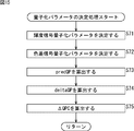
- FIG. 16 is a flowchart for explaining the quantization parameter reconstruction processing in step S42 of FIG.
- the deltaQP, ⁇ QPC, and ChromaQPOffset are supplied from the lossless encoding unit 36 to the deltaQP reception unit 94, the ⁇ QPC reception unit 96, and the ChromaQPOffset reception unit 93, respectively.
- the ChromaQPOffset receiving unit 93 receives the ChromaQPOffset from the lossless encoding unit 36 and supplies the ChromaQPOffset receiving unit 93 to the color difference signal quantization parameter reconstructing unit 92 at a predetermined timing.
- step S91 the deltaQP receiving unit 94 receives the deltaQP from the lossless encoding unit 36.
- the deltaQP reception unit 94 supplies the received deltaQP to the luminance signal quantization parameter reconstruction unit 91.
- step S92 the predQP calculation unit 97 calculates predQP using the adjacent quantization parameter from the adjacent QP buffer 95 by a method defined in HEVC or the like.
- the predQP calculation unit 97 supplies the calculated predQP to the luminance signal quantization parameter reconstruction unit 91.
- step S93 the luminance signal quantization parameter reconstruction unit 91 reconstructs the luminance signal quantization parameter using the deltaQP from the deltaQP reception unit 94 and the predQP from the predQP calculation unit 97.
- the luminance signal quantization parameter reconstruction unit 91 supplies the reconstructed luminance signal quantization parameter to the inverse quantization unit 38, the color difference signal quantization parameter reconstruction unit 92, and the adjacent QP buffer 95.
- step S94 the ⁇ QPC receiving unit 96 receives the ⁇ QPC from the lossless encoding unit 36.
- the ⁇ QPC reception unit 96 supplies the received ⁇ QPC to the color difference signal quantization parameter reconstruction unit 92.
- step S95 the color difference signal quantization parameter reconstruction unit 92 uses ⁇ QPC from the ⁇ QPC reception unit 96, ChromaQPOffset from the ChromaQPOffset reception unit 93, and the luminance signal quantization parameter from the luminance signal quantization parameter reconstruction unit 91. Then, the color difference signal quantization parameter is reconstructed.
- the color difference signal quantization parameter reconstruction unit 92 supplies the reconstructed color difference signal quantization parameter to the inverse quantization unit 38.
- the code amount of the color difference signal in the image can be controlled.
- the rate controllability regarding the color difference signal can be improved.
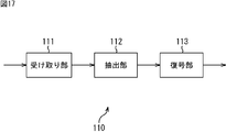
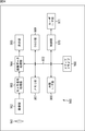
- FIG. 17 is a block diagram illustrating a configuration example of an embodiment of a decoding device to which the present disclosure is applied, which decodes an encoded stream transmitted from the encoding device 10 of FIG.
- 17 is configured by a receiving unit 111, an extracting unit 112, and a decoding unit 113.
- the receiving unit 111 of the decoding device 110 receives the encoded stream transmitted from the encoding device 10 in FIG. 8 and supplies it to the extracting unit 112.
- the extraction unit 112 extracts a parameter set and encoded data from the encoded stream supplied from the receiving unit 111 and supplies the extracted parameter set and encoded data to the decoding unit 113.
- the decoding unit 113 decodes the encoded data supplied from the extraction unit 112 by a method according to the HEVC method. At this time, the decoding unit 113 also refers to the parameter set supplied from the extraction unit 112 as necessary. The decoding unit 113 outputs an image obtained as a result of decoding.
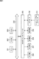
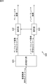
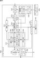
- FIG. 18 is a block diagram illustrating a configuration example of the decoding unit 113 in FIG.
- the decoding unit 113 includes a D / A conversion unit 140, a frame memory 141, a switch 142, an intra prediction unit 143, a motion compensation unit 144, a switch 145, and a color difference signal inverse quantization unit 146.
- the accumulation buffer 131 of the decoding unit 113 receives and accumulates the encoded data from the extraction unit 112 of FIG.
- the accumulation buffer 131 supplies the accumulated encoded data to the lossless decoding unit 132.
- the lossless decoding unit 132 obtains a quantized value and encoded information by performing lossless decoding such as variable length decoding and arithmetic decoding on the encoded data from the accumulation buffer 131.
- the lossless decoding unit 132 supplies the quantized value to the inverse quantization unit 133.
- the lossless decoding unit 132 supplies intra prediction mode information as encoded information to the intra prediction unit 143.
- the lossless decoding unit 132 supplies a motion vector, inter prediction mode information, information for specifying a reference image, and the like to the motion compensation unit 144.
- the lossless decoding unit 132 supplies intra prediction mode information or inter prediction mode information as encoded information to the switch 145.
- the lossless decoding unit 132 supplies offset filter information as encoded information to the adaptive offset filter 137.
- the lossless decoding unit 132 supplies filter coefficients as encoded information to the adaptive loop filter 138.
- the lossless decoding unit 132 supplies deltaQP, ⁇ QPC, and ChromaQPOffset as encoding information to the color difference signal inverse quantization unit 146.
- the signal inverse quantization unit 146 includes an inverse quantization unit 38, an inverse orthogonal transform unit 39, an addition unit 40, a deblock filter 41, an adaptive offset filter 42, an adaptive loop filter 43, a frame memory 44, a switch 45, an intra block, and the like.
- the same processing as that performed by the prediction unit 46, the motion prediction / compensation unit 47, and the color difference signal inverse quantization unit 51 is performed, whereby the image is decoded.
- the inverse quantization unit 133 is configured similarly to the inverse quantization unit 38 of FIG.
- the inverse quantization unit 133 inversely quantizes the quantization value from the lossless decoding unit 132 in units of TUs.
- the inverse quantization unit 133 supplies the orthogonal transform processing result obtained as a result to the inverse orthogonal transform unit 134.
- the inverse orthogonal transform unit 134 is configured in the same manner as the inverse orthogonal transform unit 39 of FIG.
- the inverse orthogonal transform unit 134 uses the luminance signal quantization parameter and the color difference signal quantization parameter supplied from the color difference signal inverse quantization unit 146 to inversely perform the orthogonal transform processing result supplied from the inverse quantization unit 133. Perform orthogonal transform processing.
- the inverse orthogonal transform unit 134 supplies residual information obtained as a result of the inverse orthogonal transform process to the addition unit 135.
- the addition unit 135 performs decoding by adding the residual information supplied from the inverse orthogonal transform unit 134 and the prediction image supplied from the switch 145.
- the adder 135 supplies the decoded image to the deblock filter 136 and the frame memory 141.
- the deblock filter 136 performs an adaptive deblock filter process on the image supplied from the adder 135 and supplies the resulting image to the adaptive offset filter 137.
- the adaptive offset filter 137 performs, for each LCU, the type of adaptive offset filter processing represented by the offset filter information on the image after the adaptive deblocking filter processing using the offset represented by the offset filter information from the lossless decoding unit 132. Do.
- the adaptive offset filter 137 supplies the image after the adaptive offset filter processing to the adaptive loop filter 138.
- the adaptive loop filter 138 performs an adaptive loop filter process for each LCU on the image supplied from the adaptive offset filter 137 using the filter coefficient supplied from the lossless decoding unit 132.
- the adaptive loop filter 138 supplies the resulting image to the frame memory 141 and the screen rearrangement buffer 139.
- the screen rearrangement buffer 139 stores the image supplied from the adaptive loop filter 138 in units of frames.
- the screen rearrangement buffer 139 rearranges the stored frame-by-frame images for encoding in the original display order and supplies them to the D / A conversion unit 140.
- the D / A conversion unit 140 performs D / A conversion on the frame-based image supplied from the screen rearrangement buffer 139 and outputs it.
- the frame memory 141 stores the image supplied from the adaptive loop filter 138 and the image supplied from the adding unit 135. An image adjacent to the PU among the images not subjected to the filter processing accumulated in the frame memory 141 is supplied to the intra prediction unit 143 through the switch 142 as a peripheral image. On the other hand, the filtered image stored in the frame memory 141 is supplied to the motion compensation unit 144 via the switch 142 as a reference image.
- the intra prediction unit 143 performs intra prediction processing in the optimal intra prediction mode indicated by the intra prediction mode information supplied from the lossless decoding unit 132, using the peripheral image read from the frame memory 141 via the switch 142.
- the intra prediction unit 143 supplies the prediction image generated as a result to the switch 145.
- the motion compensation unit 144 reads the reference image specified by the information specifying the reference image supplied from the lossless decoding unit 132 from the frame memory 141 via the switch 142.
- the motion compensation unit 144 performs motion compensation processing in the optimal inter prediction mode indicated by the inter prediction mode information supplied from the lossless decoding unit 132, using the motion vector and the reference image supplied from the lossless decoding unit 132.
- the motion compensation unit 144 supplies the predicted image generated as a result to the switch 145.
- the switch 145 supplies the prediction image supplied from the intra prediction unit 143 to the addition unit 135.
- the switch 145 supplies the prediction image supplied from the motion compensation unit 144 to the adding unit 135.
- the color difference signal inverse quantization unit 146 is basically configured in the same manner as the color difference signal inverse quantization unit 51 of FIG.
- Chrominance signal inverse quantization unit 146 receives DeltaQP, and DerutaQP C, and ChromaQPOffset from the lossless decoding unit 132.
- the color difference signal inverse quantization unit 146 calculates a predicted quantization parameter predQP from the quantization parameters of adjacent CUs.
- the color difference signal inverse quantization unit 146 reconstructs the luminance signal quantization parameter from the deltaQP and the predQP, and supplies the reconstructed luminance signal quantization parameter to the inverse quantization unit 133.
- the chrominance signal inverse quantization unit 146 reconstructs the chrominance signal quantization parameter from the reconstructed luminance signal quantization parameter, ⁇ QP C and Chroma QPOffset, and dequantizes the reconstructed chrominance signal quantization parameter. 133.
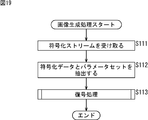
- FIG. 19 is a flowchart illustrating the image generation processing of the decoding device 110 in FIG.
- the reception unit 111 of the decoding device 110 receives the encoded stream transmitted from the encoding device 10 in FIG. 8 and supplies the encoded stream to the extraction unit 112.
- step S112 the extraction unit 112 extracts encoded data and a parameter set from the encoded stream supplied from the reception unit 111, and supplies the extracted encoded data and parameter set to the decoding unit 113.
- step S113 the decoding unit 113 performs a decoding process for decoding the encoded data supplied from the extraction unit 112 by a method according to the HEVC method, using the parameter set supplied from the extraction unit 112 as necessary. Details of this decoding process will be described with reference to FIG. Then, the process ends.
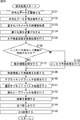
- FIG. 20 is a flowchart for explaining the details of the decoding process in step S113 of FIG.
- the accumulation buffer 131 (FIG. 18) of the decoding unit 113 receives and accumulates the encoded data in units of frames from the extraction unit 112 of FIG. 17.
- the accumulation buffer 131 supplies the accumulated encoded data to the lossless decoding unit 132.
- step S132 the lossless decoding unit 132 losslessly decodes the encoded data from the accumulation buffer 131 to obtain a quantization value and encoded information.
- the lossless decoding unit 132 supplies the quantized value to the inverse quantization unit 133.
- the lossless decoding unit 132 supplies deltaQP, ⁇ QP C , and ChromaQPOffset as encoding information to the color difference signal inverse quantization unit 146.
- the lossless decoding unit 132 supplies intra prediction mode information as encoded information to the intra prediction unit 143.
- the lossless decoding unit 132 supplies a motion vector, inter prediction mode information, information for specifying a reference image, and the like to the motion compensation unit 144.
- the lossless decoding unit 132 supplies intra prediction mode information or inter prediction mode information as encoded information to the switch 145.
- the lossless decoding unit 132 supplies offset filter information as encoded information to the adaptive offset filter 137 and supplies filter coefficients to the adaptive loop filter 138.
- step S133 the color difference signal inverse quantization unit 146 performs the quantization parameter reconstruction processing similar to that in FIG.
- step S133 the reconstructed luminance signal and color difference signal, and the respective quantization parameters are supplied to the inverse quantization unit 133.
- step S134 the inverse quantization unit 133 uses the luminance signal quantization parameter and the color difference signal quantization parameter from the color difference signal inverse quantization unit 146 to calculate the quantization value supplied from the lossless decoding unit 132. Inverse quantization.
- the inverse quantization unit 133 supplies the orthogonal transform processing result obtained as a result of the inverse quantization to the inverse orthogonal transform unit 134.
- step S135 the inverse orthogonal transform unit 134 performs an orthogonal transform process on the orthogonal transform process result from the inverse quantization unit 133.
- step S136 the motion compensation unit 144 determines whether or not the inter prediction mode information is supplied from the lossless decoding unit 132. If it is determined in step S136 that the inter prediction mode information has been supplied, the process proceeds to step S137.
- step S137 the motion compensation unit 144 reads a reference image based on the reference image specifying information supplied from the lossless decoding unit 132, and uses the motion vector and the reference image to determine the optimal inter prediction mode indicated by the inter prediction mode information. Perform motion compensation processing.
- the motion compensation unit 144 supplies the predicted image generated as a result to the addition unit 135 via the switch 145, and the process proceeds to step S139.
- step S136 determines whether the inter prediction mode information is supplied. If it is determined in step S136 that the inter prediction mode information is supplied, that is, if the intra prediction mode information is supplied to the intra prediction unit 143, the process proceeds to step S138.
- step S138 the intra prediction unit 143 performs an intra prediction process in the intra prediction mode indicated by the intra prediction mode information, using the peripheral image read from the frame memory 141 via the switch 142.
- the intra prediction unit 143 supplies the prediction image generated as a result of the intra prediction process to the addition unit 135 via the switch 145, and the process proceeds to step S139.
- step S139 the adding unit 135 performs decoding by adding the residual information supplied from the inverse orthogonal transform unit 134 and the prediction image supplied from the switch 145.
- the adder 135 supplies the decoded image to the deblock filter 136 and the frame memory 141.
- step S140 the deblocking filter 136 performs deblocking filtering on the image supplied from the adding unit 135 to remove block distortion.
- the deblocking filter 136 supplies the resulting image to the adaptive offset filter 137.
- step S141 the adaptive offset filter 137 performs adaptive offset filter processing for each LCU on the image after the deblocking filter processing by the deblocking filter 136 based on the offset filter information supplied from the lossless decoding unit 132. .
- the adaptive offset filter 137 supplies the image after the adaptive offset filter processing to the adaptive loop filter 138.
- step S142 the adaptive loop filter 138 performs adaptive loop filter processing for each LCU on the image supplied from the adaptive offset filter 137 using the filter coefficient supplied from the lossless decoding unit 132.
- the adaptive loop filter 138 supplies the resulting image to the frame memory 141 and the screen rearrangement buffer 139.
- step S143 the frame memory 141 stores the image supplied from the adding unit 135 and the image supplied from the adaptive loop filter 138.
- An image adjacent to the PU among the images not subjected to the filter processing accumulated in the frame memory 141 is supplied to the intra prediction unit 143 through the switch 142 as a peripheral image.
- the filtered image stored in the frame memory 141 is supplied to the motion compensation unit 144 via the switch 142 as a reference image.
- step S144 the screen rearrangement buffer 139 stores the image supplied from the adaptive loop filter 138 in units of frames, and rearranges the stored frame-by-frame images for encoding in the original display order. To the D / A converter 140.
- step S145 the D / A conversion unit 140 performs D / A conversion on the frame unit image supplied from the screen rearrangement buffer 139 and outputs the image. Then, the process returns to step S113 in FIG. 19 and ends.
- the decoding apparatus 110 can also control the code amount of the color difference signal in the image. In particular, even when a wide color gamut signal is input, the rate controllability regarding the color difference signal can be improved.
- the method according to HEVC is used as the encoding method.
- the present technology is not limited to this, and other encoding / decoding methods can be applied.
- the present disclosure discloses, for example, image information (bitstream) compressed by orthogonal transformation such as discrete cosine transformation and motion compensation, such as HEVC, satellite broadcasting, cable television, the Internet, or a mobile phone.
- the present invention can be applied to an image encoding device and an image decoding device used when receiving via a network medium. Further, the present disclosure can be applied to an image encoding device and an image decoding device that are used when processing on a storage medium such as an optical disk, a magnetic disk, and a flash memory.
- ⁇ Second Embodiment> (Description of computer to which the present disclosure is applied)
- the series of processes described above can be executed by hardware or can be executed by software.
- a program constituting the software is installed in the computer.
- the computer includes, for example, a general-purpose personal computer capable of executing various functions by installing various programs by installing a computer incorporated in dedicated hardware.
- FIG. 21 is a block diagram showing an example of the hardware configuration of a computer that executes the above-described series of processing by a program.
- a CPU Central Processing Unit
- ROM Read Only Memory
- RAM Random Access Memory
- An input / output interface 205 is further connected to the bus 204.
- An input unit 206, an output unit 207, a storage unit 208, a communication unit 209, and a drive 210 are connected to the input / output interface 205.
- the input unit 206 includes a keyboard, a mouse, a microphone, and the like.
- the output unit 207 includes a display, a speaker, and the like.
- the storage unit 208 includes a hard disk, a nonvolatile memory, and the like.
- the communication unit 209 includes a network interface and the like.
- the drive 210 drives a removable medium 211 such as a magnetic disk, an optical disk, a magneto-optical disk, or a semiconductor memory.
- the CPU 201 loads, for example, the program stored in the storage unit 208 to the RAM 203 via the input / output interface 205 and the bus 204 and executes the program. Is performed.
- the program executed by the computer (CPU 201) can be provided by being recorded in the removable medium 211 as a package medium or the like, for example.
- the program can be provided via a wired or wireless transmission medium such as a local area network, the Internet, or digital satellite broadcasting.
- the program can be installed in the storage unit 208 via the input / output interface 205 by attaching the removable medium 211 to the drive 210.
- the program can be received by the communication unit 209 via a wired or wireless transmission medium and installed in the storage unit 208.
- the program can be installed in the ROM 202 or the storage unit 208 in advance.
- the program executed by the computer may be a program that is processed in time series in the order described in this specification, or in parallel or at a necessary timing such as when a call is made. It may be a program for processing.
- FIG. 22 shows an example of the multi-view image encoding method.
- the multi-viewpoint image includes images of a plurality of viewpoints (views). Multiple views of this multi-viewpoint image are encoded using the base view that encodes and decodes using only the image of its own view without using the image of the other view, and the image of the other view.
- -It consists of a non-base view that performs decoding. For the non-base view, an image of the base view may be used, or an image of another non-base view may be used.
- the image of each view is encoded / decoded.
- the method of the first embodiment described above is used. You may make it apply. In this way, the code amount of the color difference signal in the image can be controlled. In particular, when a wide color gamut signal is input, the rate controllability regarding the color difference signal can be improved.
- the parameters used in the method of the first embodiment described above may be shared. More specifically, for example, deltaQP, ⁇ QP C , and ChromaQPOffset as encoding information may be shared in encoding / decoding of each view. Of course, other necessary information may be shared in encoding / decoding of each view.
- FIG. 23 is a diagram illustrating a multi-view image encoding apparatus that performs the multi-view image encoding described above. As illustrated in FIG. 23, the multi-view image encoding apparatus 600 includes an encoding unit 601, an encoding unit 602, and a multiplexing unit 603.
- the cocoon encoding unit 601 encodes the base view image and generates a base view image encoded stream.
- the encoding unit 602 encodes the non-base view image and generates a non-base view image encoded stream.
- the multiplexing unit 603 multiplexes the base view image encoded stream generated by the encoding unit 601 and the non-base view image encoded stream generated by the encoding unit 602 to generate a multi-view image encoded stream. To do.
- the encoding device 10 (FIG. 8) can be applied to the encoding unit 601 and the encoding unit 602 of the multi-view image encoding device 600. That is, in the encoding for each view, the code amount of the color difference signal in the image can be controlled. In particular, when a wide color gamut signal is input, the rate controllability regarding the color difference signal can be improved. Also, the encoding unit 601 and the encoding unit 602 can perform encoding using the same flags and parameters (for example, syntax elements related to processing between images) (that is, share the flags and parameters). Therefore, it is possible to suppress a reduction in encoding efficiency.
- flags and parameters for example, syntax elements related to processing between images
- FIG. 24 is a diagram illustrating a multi-view image decoding apparatus that performs the above-described multi-view image decoding.
- the multi-view image decoding device 610 includes a demultiplexing unit 611, a decoding unit 612, and a decoding unit 613.
- the demultiplexing unit 611 demultiplexes the multi-view image encoded stream in which the base view image encoded stream and the non-base view image encoded stream are multiplexed, and the base view image encoded stream and the non-base view image The encoded stream is extracted.
- the decoding unit 612 decodes the base view image encoded stream extracted by the demultiplexing unit 611 to obtain a base view image.
- the decoding unit 613 decodes the non-base view image encoded stream extracted by the demultiplexing unit 611 to obtain a non-base view image.
- the decoding device 110 (FIG. 17) can be applied to the decoding unit 612 and the decoding unit 613 of the multi-view image decoding device 610. That is, in the decoding for each view, the code amount of the color difference signal in the image can be controlled. In particular, when a wide color gamut signal is input, an encoded stream with improved encoding efficiency can be decoded by improving the rate controllability regarding the color difference signal.
- the decoding unit 612 and the decoding unit 613 can perform decoding using the same flags and parameters (for example, syntax elements related to processing between images) (that is, the flags and parameters can be shared). Therefore, it is possible to suppress a reduction in encoding efficiency.
- FIG. 25 shows an example of a hierarchical image encoding method.
- Hierarchical image coding is a method in which image data is divided into a plurality of layers (hierarchized) so as to have a scalable function with respect to a predetermined parameter, and is encoded for each layer.
- Hierarchical image decoding is decoding corresponding to the hierarchical image encoding.
- the hierarchized image includes images of a plurality of hierarchies (layers) having different predetermined parameter values.
- a plurality of layers of this hierarchical image are encoded / decoded using only the image of the own layer without using the image of the other layer, and encoded / decoded using the image of the other layer.
- It consists of a non-base layer (also called enhancement layer) that performs decoding.
- the non-base layer an image of the base layer may be used, or an image of another non-base layer may be used.
- the non-base layer is composed of difference image data (difference data) between its own image and an image of another layer so that redundancy is reduced.
- difference image data difference data
- an image with lower quality than the original image can be obtained using only the base layer data.
- an original image that is, a high-quality image
- image compression information of only the base layer (base layer) is transmitted, and a moving image with low spatiotemporal resolution or poor image quality is reproduced.
- image enhancement information of the enhancement layer is transmitted.
- Image compression information corresponding to the capabilities of the terminal and the network can be transmitted from the server without performing transcoding processing, such as playing a moving image with high image quality.
- the image of each layer is encoded / decoded.
- the method of the first embodiment described above is used. May be applied. In this way, the code amount of the color difference signal in the image can be controlled. In particular, when a wide color gamut signal is input, the rate controllability regarding the color difference signal can be improved.
- the flags and parameters used in the method of the first embodiment described above may be shared. More specifically, for example, deltaQP, ⁇ QP C , and ChromaQPOffset as encoding information may be shared in encoding / decoding of each layer. Of course, other necessary information may be shared in encoding / decoding of each layer.
- parameters having a scalable function are arbitrary.
- the spatial resolution as shown in FIG. 26 may be used as the parameter (spatial scalability).
- the resolution of the image is different for each layer. That is, in this case, as shown in FIG. 26, each picture has two layers of a base layer having a spatially lower resolution than the original image and an enhancement layer in which the original spatial resolution can be obtained by combining with the base layer. Is layered.
- this number of hierarchies is an example, and the number of hierarchies can be hierarchized.
- a temporal resolution as shown in FIG. 27 may be applied (temporalabilityscalability).
- this temporal scalability temporary scalability
- the frame rate is different for each layer. That is, in this case, as shown in FIG. 27, each picture is divided into two layers of a base layer having a lower frame rate than the original moving image and an enhancement layer in which the original frame rate can be obtained by combining with the base layer. Layered.
- this number of hierarchies is an example, and the number of hierarchies can be hierarchized.
- a signal-to-noise ratio (SNR (Signal to Noise ratio)) may be applied (SNR ⁇ ⁇ scalability) as a parameter for providing such scalability.
- SNR Signal-to-noise ratio
- the SN ratio is different for each layer. That is, in this case, as shown in FIG. 28, each picture is hierarchized into two layers: a base layer having a lower SNR than the original image, and an enhancement layer from which the original SNR is obtained by combining with the base layer.
- this number of hierarchies is an example, and the number of hierarchies can be hierarchized.
- bit depth can also be used as a parameter for providing scalability (bit-depth scalability).
- bit-depth scalability bit depth scalability
- the bit depth differs for each layer.
- the base layer is composed of an 8-bit image, and an enhancement layer is added to the base layer, whereby a 10-bit image can be obtained.
- a chroma format can be used as a parameter for providing scalability (chroma scalability).
- the chroma format differs for each layer.
- the base layer is composed of component images in 4: 2: 0 format, and by adding an enhancement layer (enhancement layer) to this, a component image in 4: 2: 2 format can be obtained. Can be.
- FIG. 29 is a diagram illustrating a hierarchical image encoding apparatus that performs the above-described hierarchical image encoding.
- the hierarchical image encoding device 620 includes an encoding unit 621, an encoding unit 622, and a multiplexing unit 623.
- the cocoon encoding unit 621 encodes the base layer image and generates a base layer image encoded stream.
- the encoding unit 622 encodes the non-base layer image and generates a non-base layer image encoded stream.
- the multiplexing unit 623 multiplexes the base layer image encoded stream generated by the encoding unit 621 and the non-base layer image encoded stream generated by the encoding unit 622 to generate a hierarchical image encoded stream. .
- the encoding device 10 (FIG. 8) can be applied to the encoding unit 621 and the encoding unit 622 of the hierarchical image encoding device 620. That is, in the encoding for each layer, the code amount of the color difference signal in the image can be controlled. In particular, when a wide color gamut signal is input, the rate controllability regarding the color difference signal can be improved. Also, the encoding unit 621 and the encoding unit 622 can perform control of intra prediction filter processing using the same flags and parameters (for example, syntax elements related to processing between images) (that is, the intra prediction processing). Therefore, it is possible to share a flag and a parameter), and it is possible to suppress a reduction in encoding efficiency.
- the encoding unit 621 and the encoding unit 622 can perform control of intra prediction filter processing using the same flags and parameters (for example, syntax elements related to processing between images) (that is, the intra prediction processing). Therefore, it is possible to share a flag and a parameter), and it is possible
- FIG. 30 is a diagram illustrating a hierarchical image decoding apparatus that performs the hierarchical image decoding described above.
- the hierarchical image decoding device 630 includes a demultiplexing unit 631, a decoding unit 632, and a decoding unit 633.
- the demultiplexing unit 631 demultiplexes the hierarchical image encoded stream in which the base layer image encoded stream and the non-base layer image encoded stream are multiplexed, and the base layer image encoded stream and the non-base layer image code Stream.
- the decoding unit 632 decodes the base layer image encoded stream extracted by the demultiplexing unit 631 to obtain a base layer image.
- the decoding unit 633 decodes the non-base layer image encoded stream extracted by the demultiplexing unit 631 to obtain a non-base layer image.
- the decoding device 110 (FIG. 17) can be applied to the decoding unit 632 and the decoding unit 633 of the hierarchical image decoding device 630. That is, in the decoding for each layer, the code amount of the color difference signal in the image can be controlled. When a wide color gamut signal is input, an encoded stream with improved encoding efficiency can be decoded by improving the rate controllability regarding the color difference signal.
- the decoding unit 612 and the decoding unit 613 can perform decoding using the same flags and parameters (for example, syntax elements related to processing between images) (that is, the flags and parameters can be shared). Therefore, it is possible to suppress a reduction in encoding efficiency.
- FIG. 31 illustrates a schematic configuration of a television apparatus to which the present disclosure is applied.
- the television apparatus 900 includes an antenna 901, a tuner 902, a demultiplexer 903, a decoder 904, a video signal processing unit 905, a display unit 906, an audio signal processing unit 907, a speaker 908, and an external interface unit 909. Furthermore, the television apparatus 900 includes a control unit 910, a user interface unit 911, and the like.
- the tuner 902 selects a desired channel from the broadcast wave signal received by the antenna 901, demodulates it, and outputs the obtained encoded bit stream to the demultiplexer 903.
- the demultiplexer 903 extracts video and audio packets of the program to be viewed from the encoded bit stream, and outputs the extracted packet data to the decoder 904. Further, the demultiplexer 903 supplies a packet of data such as EPG (Electronic Program Guide) to the control unit 910. If scrambling is being performed, descrambling is performed by a demultiplexer or the like.
- EPG Electronic Program Guide
- the decoder 904 performs packet decoding processing, and outputs video data generated by the decoding processing to the video signal processing unit 905 and audio data to the audio signal processing unit 907.
- the video signal processing unit 905 performs noise removal, video processing according to user settings, and the like on the video data.
- the video signal processing unit 905 generates video data of a program to be displayed on the display unit 906, image data by processing based on an application supplied via a network, and the like.
- the video signal processing unit 905 generates video data for displaying a menu screen for selecting an item and the like, and superimposes the video data on the video data of the program.
- the video signal processing unit 905 generates a drive signal based on the video data generated in this way, and drives the display unit 906.
- the display unit 906 drives a display device (for example, a liquid crystal display element or the like) based on a drive signal from the video signal processing unit 905 to display a program video or the like.
- a display device for example, a liquid crystal display element or the like
- the audio signal processing unit 907 performs predetermined processing such as noise removal on the audio data, performs D / A conversion processing and amplification processing on the processed audio data, and outputs the audio data to the speaker 908.
- the external interface unit 909 is an interface for connecting to an external device or a network, and transmits and receives data such as video data and audio data.
- a user interface unit 911 is connected to the control unit 910.
- the user interface unit 911 includes an operation switch, a remote control signal receiving unit, and the like, and supplies an operation signal corresponding to a user operation to the control unit 910.
- the control unit 910 is configured using a CPU (Central Processing Unit), a memory, and the like.
- the memory stores a program executed by the CPU, various data necessary for the CPU to perform processing, EPG data, data acquired via a network, and the like.
- the program stored in the memory is read and executed by the CPU at a predetermined timing such as when the television device 900 is activated.
- the CPU executes each program to control each unit so that the television device 900 operates in accordance with the user operation.
- the television device 900 includes a bus 912 for connecting the tuner 902, the demultiplexer 903, the video signal processing unit 905, the audio signal processing unit 907, the external interface unit 909, and the control unit 910.
- the decoder 904 is provided with the function of the decoding apparatus (decoding method) of the present application. Therefore, it is possible to control the code amount of the color difference signal in the image in the decoding process of the encoded stream. In particular, when a wide color gamut signal is input, the rate controllability regarding the color difference signal can be improved.
- FIG. 32 illustrates a schematic configuration of a mobile phone to which the present disclosure is applied.
- the cellular phone 920 includes a communication unit 922, an audio codec 923, a camera unit 926, an image processing unit 927, a demultiplexing unit 928, a recording / reproducing unit 929, a display unit 930, and a control unit 931. These are connected to each other via a bus 933.
- an antenna 921 is connected to the communication unit 922, and a speaker 924 and a microphone 925 are connected to the audio codec 923. Further, an operation unit 932 is connected to the control unit 931.
- the mobile phone 920 performs various operations such as transmission / reception of voice signals, transmission / reception of e-mail and image data, image shooting, and data recording in various modes such as a voice call mode and a data communication mode.
- the voice signal generated by the microphone 925 is converted into voice data and compressed by the voice codec 923 and supplied to the communication unit 922.
- the communication unit 922 performs audio data modulation processing, frequency conversion processing, and the like to generate a transmission signal.
- the communication unit 922 supplies a transmission signal to the antenna 921 and transmits it to a base station (not shown).
- the communication unit 922 performs amplification, frequency conversion processing, demodulation processing, and the like of the reception signal received by the antenna 921, and supplies the obtained audio data to the audio codec 923.
- the audio codec 923 performs data expansion of the audio data and conversion into an analog audio signal and outputs the result to the speaker 924.
- the control unit 931 receives character data input by operating the operation unit 932 and displays the input characters on the display unit 930.
- the control unit 931 generates mail data based on a user instruction or the like in the operation unit 932 and supplies the mail data to the communication unit 922.
- the communication unit 922 performs mail data modulation processing, frequency conversion processing, and the like, and transmits the obtained transmission signal from the antenna 921.
- the communication unit 922 performs amplification, frequency conversion processing, demodulation processing, and the like of the reception signal received by the antenna 921, and restores mail data. This mail data is supplied to the display unit 930 to display the mail contents.
- the mobile phone 920 can also store the received mail data in a storage medium by the recording / playback unit 929.
- the storage medium is any rewritable storage medium.
- the storage medium is a removable memory such as a RAM, a semiconductor memory such as a built-in flash memory, a hard disk, a magnetic disk, a magneto-optical disk, an optical disk, a USB (Universal Serial Bus) memory, or a memory card.
- the image data generated by the camera unit 926 is supplied to the image processing unit 927.
- the image processing unit 927 performs encoding processing of image data and generates encoded data.
- the demultiplexing unit 928 multiplexes the encoded data generated by the image processing unit 927 and the audio data supplied from the audio codec 923 by a predetermined method, and supplies the multiplexed data to the communication unit 922.
- the communication unit 922 performs modulation processing and frequency conversion processing of multiplexed data, and transmits the obtained transmission signal from the antenna 921.
- the communication unit 922 performs amplification, frequency conversion processing, demodulation processing, and the like of the reception signal received by the antenna 921, and restores multiplexed data. This multiplexed data is supplied to the demultiplexing unit 928.
- the demultiplexing unit 928 performs demultiplexing of the multiplexed data, and supplies the encoded data to the image processing unit 927 and the audio data to the audio codec 923.
- the image processing unit 927 performs a decoding process on the encoded data to generate image data.
- the image data is supplied to the display unit 930 and the received image is displayed.
- the audio codec 923 converts the audio data into an analog audio signal, supplies the analog audio signal to the speaker 924, and outputs the received audio.
- the image processing unit 927 is provided with the functions of the encoding device and the decoding device (encoding method and decoding method) of the present application. For this reason, the code amount of the color difference signal in the image can be controlled. In particular, when a wide color gamut signal is input, the rate controllability regarding the color difference signal can be improved.
- FIG. 33 illustrates a schematic configuration of a recording / reproducing apparatus to which the present disclosure is applied.
- the recording / reproducing apparatus 940 records, for example, audio data and video data of a received broadcast program on a recording medium, and provides the recorded data to the user at a timing according to a user instruction.
- the recording / reproducing device 940 can also acquire audio data and video data from another device, for example, and record them on a recording medium. Further, the recording / reproducing apparatus 940 decodes and outputs the audio data and video data recorded on the recording medium, thereby enabling image display and audio output on the monitor apparatus or the like.
- the recording / reproducing apparatus 940 includes a tuner 941, an external interface unit 942, an encoder 943, an HDD (Hard Disk Drive) unit 944, a disk drive 945, a selector 946, a decoder 947, an OSD (On-Screen Display) unit 948, a control unit 949, A user interface unit 950 is included.
- Tuner 941 selects a desired channel from a broadcast signal received by an antenna (not shown).
- the tuner 941 outputs an encoded bit stream obtained by demodulating the received signal of a desired channel to the selector 946.
- the external interface unit 942 includes at least one of an IEEE 1394 interface, a network interface unit, a USB interface, a flash memory interface, and the like.
- the external interface unit 942 is an interface for connecting to an external device, a network, a memory card, and the like, and receives data such as video data and audio data to be recorded.
- the encoder 943 performs encoding by a predetermined method when the video data and audio data supplied from the external interface unit 942 are not encoded, and outputs an encoded bit stream to the selector 946.
- the HDD unit 944 records content data such as video and audio, various programs, and other data on a built-in hard disk, and reads them from the hard disk during playback.
- the disk drive 945 records and reproduces signals with respect to the mounted optical disk.
- An optical disk such as a DVD disk (DVD-Video, DVD-RAM, DVD-R, DVD-RW, DVD + R, DVD + RW, etc.), a Blu-ray (registered trademark) disk, or the like.
- the selector 946 selects one of the encoded bit streams from the tuner 941 or the encoder 943 and supplies it to either the HDD unit 944 or the disk drive 945 when recording video or audio. Further, the selector 946 supplies the encoded bit stream output from the HDD unit 944 or the disk drive 945 to the decoder 947 at the time of reproduction of video and audio.
- the decoder 947 performs a decoding process on the encoded bit stream.
- the decoder 947 supplies the video data generated by performing the decoding process to the OSD unit 948.
- the decoder 947 outputs audio data generated by performing the decoding process.
- the OSD unit 948 generates video data for displaying a menu screen for selecting an item and the like, and superimposes it on the video data output from the decoder 947 and outputs the video data.
- a user interface unit 950 is connected to the control unit 949.
- the user interface unit 950 includes an operation switch, a remote control signal receiving unit, and the like, and supplies an operation signal corresponding to a user operation to the control unit 949.
- the control unit 949 is configured using a CPU, a memory, and the like.
- the memory stores programs executed by the CPU and various data necessary for the CPU to perform processing.
- the program stored in the memory is read and executed by the CPU at a predetermined timing such as when the recording / reproducing apparatus 940 is activated.
- the CPU executes the program to control each unit so that the recording / reproducing device 940 operates according to the user operation.
- the decoder 947 is provided with the function of the decoding apparatus (decoding method) of the present application. For this reason, in the decoding of the encoded stream, it is possible to control the code amount of the color difference signal in the image. In particular, when a wide color gamut signal is input, the rate controllability regarding the color difference signal can be improved.
- FIG. 34 illustrates a schematic configuration of an imaging apparatus to which the present disclosure is applied.
- the imaging device 960 images a subject, displays an image of the subject on a display unit, and records it on a recording medium as image data.
- the imaging device 960 includes an optical block 961, an imaging unit 962, a camera signal processing unit 963, an image data processing unit 964, a display unit 965, an external interface unit 966, a memory unit 967, a media drive 968, an OSD unit 969, and a control unit 970. Have. In addition, a user interface unit 971 is connected to the control unit 970. Furthermore, the image data processing unit 964, the external interface unit 966, the memory unit 967, the media drive 968, the OSD unit 969, the control unit 970, and the like are connected via a bus 972.
- the optical block 961 is configured using a focus lens, a diaphragm mechanism, and the like.
- the optical block 961 forms an optical image of the subject on the imaging surface of the imaging unit 962.
- the imaging unit 962 is configured using a CCD or CMOS image sensor, generates an electrical signal corresponding to the optical image by photoelectric conversion, and supplies the electrical signal to the camera signal processing unit 963.
- the camera signal processing unit 963 performs various camera signal processing such as knee correction, gamma correction, and color correction on the electrical signal supplied from the imaging unit 962.
- the camera signal processing unit 963 supplies the image data after the camera signal processing to the image data processing unit 964.
- the image data processing unit 964 performs an encoding process on the image data supplied from the camera signal processing unit 963.
- the image data processing unit 964 supplies the encoded data generated by performing the encoding process to the external interface unit 966 and the media drive 968. Further, the image data processing unit 964 performs a decoding process on the encoded data supplied from the external interface unit 966 and the media drive 968.
- the image data processing unit 964 supplies the image data generated by performing the decoding process to the display unit 965. Further, the image data processing unit 964 superimposes the processing for supplying the image data supplied from the camera signal processing unit 963 to the display unit 965 and the display data acquired from the OSD unit 969 on the image data. To supply.
- the OSD unit 969 generates display data such as a menu screen and icons made up of symbols, characters, or figures and outputs them to the image data processing unit 964.
- the external interface unit 966 includes, for example, a USB input / output terminal, and is connected to a printer when printing an image.
- a drive is connected to the external interface unit 966 as necessary, a removable medium such as a magnetic disk or an optical disk is appropriately mounted, and a computer program read from them is installed as necessary.
- the external interface unit 966 has a network interface connected to a predetermined network such as a LAN or the Internet.
- the control unit 970 reads encoded data from the media drive 968 in accordance with an instruction from the user interface unit 971, and supplies the encoded data to the other device connected via the network from the external interface unit 966. it can.
- the control unit 970 may acquire encoded data and image data supplied from another device via the network via the external interface unit 966 and supply the acquired data to the image data processing unit 964. it can.
- any readable / writable removable medium such as a magnetic disk, a magneto-optical disk, an optical disk, or a semiconductor memory is used.
- the recording medium may be any type of removable medium, and may be a tape device, a disk, or a memory card. Of course, a non-contact IC (Integrated Circuit) card may be used.
- media drive 968 and the recording medium may be integrated and configured by a non-portable storage medium such as a built-in hard disk drive or an SSD (Solid State Drive).
- a non-portable storage medium such as a built-in hard disk drive or an SSD (Solid State Drive).
- the control unit 970 is configured using a CPU.
- the memory unit 967 stores a program executed by the control unit 970, various data necessary for the control unit 970 to perform processing, and the like.
- the program stored in the memory unit 967 is read and executed by the control unit 970 at a predetermined timing such as when the imaging device 960 is activated.
- the control unit 970 controls each unit so that the imaging device 960 performs an operation according to a user operation by executing a program.
- the image data processing unit 964 is provided with the functions of the encoding apparatus and decoding apparatus (encoding method and decoding method) of the present application. Therefore, it is possible to control the code amount of the color difference signal in the image in encoding or decoding of the encoded stream. In particular, when a wide color gamut signal is input, the rate controllability regarding the color difference signal can be improved.
- Scalable encoding is used for selection of data to be transmitted, as in the example shown in FIG.
- the distribution server 1002 reads the scalable encoded data stored in the scalable encoded data storage unit 1001, and via the network 1003, the personal computer 1004, the AV device 1005, the tablet This is distributed to the terminal device such as the device 1006 and the mobile phone 1007.
- the distribution server 1002 selects and transmits encoded data of appropriate quality according to the capability of the terminal device, the communication environment, and the like. Even if the distribution server 1002 transmits unnecessarily high-quality data, the terminal device does not always obtain a high-quality image, and may cause a delay or an overflow. Moreover, there is a possibility that the communication band is unnecessarily occupied or the load on the terminal device is unnecessarily increased. On the other hand, even if the distribution server 1002 transmits unnecessarily low quality data, there is a possibility that an image with sufficient image quality cannot be obtained in the terminal device. Therefore, the distribution server 1002 appropriately reads and transmits the scalable encoded data stored in the scalable encoded data storage unit 1001 as encoded data having an appropriate quality with respect to the capability and communication environment of the terminal device. .
- the scalable encoded data storage unit 1001 stores scalable encoded data (BL + EL) 1011 encoded in a scalable manner.
- the scalable encoded data (BL + EL) 1011 is encoded data including both a base layer and an enhancement layer, and is a data that can be decoded to obtain both a base layer image and an enhancement layer image. It is.
- the distribution server 1002 selects an appropriate layer according to the capability of the terminal device that transmits data, the communication environment, and the like, and reads the data of the layer. For example, the distribution server 1002 reads high-quality scalable encoded data (BL + EL) 1011 from the scalable encoded data storage unit 1001 and transmits it to the personal computer 1004 and the tablet device 1006 with high processing capability as they are. . On the other hand, for example, the distribution server 1002 extracts base layer data from the scalable encoded data (BL + EL) 1011 for the AV device 1005 and the cellular phone 1007 having a low processing capability, and performs scalable encoding. Although it is data of the same content as the data (BL + EL) 1011, it is transmitted as scalable encoded data (BL) 1012 having a lower quality than the scalable encoded data (BL + EL) 1011.
- BL scalable encoded data
- scalable encoded data By using scalable encoded data in this way, the amount of data can be easily adjusted, so that the occurrence of delay and overflow can be suppressed, and the unnecessary increase in the load on the terminal device and communication medium can be suppressed. be able to.
- scalable encoded data (BL + EL) 1011 since scalable encoded data (BL + EL) 1011 has reduced redundancy between layers, the amount of data can be reduced as compared with the case where encoded data of each layer is used as individual data. . Therefore, the storage area of the scalable encoded data storage unit 1001 can be used more efficiently.
- the hardware performance of the terminal device varies depending on the device.
- the application which a terminal device performs is also various, the capability of the software is also various.
- the network 1003 serving as a communication medium can be applied to any communication network including wired, wireless, or both, such as the Internet and a LAN (Local Area Network), and has various data transmission capabilities. Furthermore, there is a risk of change due to other communications.
- the distribution server 1002 communicates with the terminal device that is the data transmission destination before starting data transmission, and the hardware performance of the terminal device, the performance of the application (software) executed by the terminal device, etc. Information regarding the capability of the terminal device and information regarding the communication environment such as the available bandwidth of the network 1003 may be obtained. The distribution server 1002 may select an appropriate layer based on the information obtained here.
- the layer extraction may be performed by the terminal device.
- the personal computer 1004 may decode the transmitted scalable encoded data (BL + EL) 1011 and display a base layer image or an enhancement layer image. Further, for example, the personal computer 1004 extracts the base layer scalable encoded data (BL) 1012 from the transmitted scalable encoded data (BL + EL) 1011 and stores it or transfers it to another device. The base layer image may be displayed after decoding.
- the numbers of the scalable encoded data storage unit 1001, the distribution server 1002, the network 1003, and the terminal devices are arbitrary.
- the example in which the distribution server 1002 transmits data to the terminal device has been described, but the usage example is not limited to this.
- the data transmission system 1000 may be any system as long as it transmits a scalable encoded data to a terminal device by selecting an appropriate layer according to the capability of the terminal device or a communication environment. Can be applied to the system.
- scalable coding is used for transmission via a plurality of communication media, for example, as in the example shown in FIG.
- a broadcasting station 1101 transmits base layer scalable encoded data (BL) 1121 by terrestrial broadcasting 1111.
- the broadcast station 1101 transmits enhancement layer scalable encoded data (EL) 1122 via an arbitrary network 1112 including a wired or wireless communication network or both (for example, packetized transmission).
- BL base layer scalable encoded data
- EL enhancement layer scalable encoded data
- the terminal apparatus 1102 has a reception function of the terrestrial broadcast 1111 broadcast by the broadcast station 1101 and receives base layer scalable encoded data (BL) 1121 transmitted via the terrestrial broadcast 1111.
- the terminal apparatus 1102 further has a communication function for performing communication via the network 1112, and receives enhancement layer scalable encoded data (EL) 1122 transmitted via the network 1112.
- BL base layer scalable encoded data
- EL enhancement layer scalable encoded data
- the terminal device 1102 decodes the base layer scalable encoded data (BL) 1121 acquired via the terrestrial broadcast 1111 according to, for example, a user instruction, and obtains or stores a base layer image. Or transmit to other devices.
- BL base layer scalable encoded data
- the terminal device 1102 for example, in response to a user instruction, the base layer scalable encoded data (BL) 1121 acquired via the terrestrial broadcast 1111 and the enhancement layer scalable encoded acquired via the network 1112 Data (EL) 1122 is combined to obtain scalable encoded data (BL + EL), or decoded to obtain an enhancement layer image, stored, or transmitted to another device.
- BL base layer scalable encoded data
- EL enhancement layer scalable encoded acquired via the network 1112 Data
- the scalable encoded data can be transmitted via a communication medium that is different for each layer, for example. Therefore, the load can be distributed, and the occurrence of delay and overflow can be suppressed.
- the communication medium used for transmission may be selected for each layer. For example, scalable encoded data (BL) 1121 of a base layer having a relatively large amount of data is transmitted via a communication medium having a wide bandwidth, and scalable encoded data (EL) 1122 having a relatively small amount of data is transmitted. You may make it transmit via a communication medium with a narrow bandwidth. Further, for example, the communication medium for transmitting the enhancement layer scalable encoded data (EL) 1122 is switched between the network 1112 and the terrestrial broadcast 1111 according to the available bandwidth of the network 1112. May be. Of course, the same applies to data of an arbitrary layer.
- the number of layers is arbitrary, and the number of communication media used for transmission is also arbitrary.
- the number of terminal devices 1102 serving as data distribution destinations is also arbitrary.
- broadcasting from the broadcasting station 1101 has been described as an example, but the usage example is not limited to this.
- the data transmission system 1100 can be applied to any system as long as it is a system that divides scalable encoded data into a plurality of layers and transmits them through a plurality of lines.
- scalable coding is used for storing coded data, for example, as in the example shown in FIG.
- the imaging device 1201 performs scalable coding on image data obtained by imaging the subject 1211, and as scalable coded data (BL + EL) 1221, a scalable coded data storage device 1202. To supply.
- the scalable encoded data storage device 1202 stores the scalable encoded data (BL + EL) 1221 supplied from the imaging device 1201 with quality according to the situation. For example, in the normal case, the scalable encoded data storage device 1202 extracts base layer data from the scalable encoded data (BL + EL) 1221, and the base layer scalable encoded data ( BL) 1222. On the other hand, for example, in the case of attention, the scalable encoded data storage device 1202 stores scalable encoded data (BL + EL) 1221 with high quality and a large amount of data.
- the scalable encoded data storage device 1202 can store an image with high image quality only when necessary, so that an increase in the amount of data can be achieved while suppressing a reduction in the value of the image due to image quality degradation. And the use efficiency of the storage area can be improved.
- the imaging device 1201 is a surveillance camera.
- the monitoring target for example, an intruder
- the content of the captured image is likely to be unimportant, so reduction of the data amount is given priority, and the image data (scalable coding) Data) is stored in low quality.
- the image quality is given priority and the image data (scalable) (Encoded data) is stored with high quality.
- whether it is normal time or attention time may be determined by the scalable encoded data storage device 1202 analyzing an image, for example.
- the imaging apparatus 1201 may make a determination, and the determination result may be transmitted to the scalable encoded data storage device 1202.
- the criterion for determining whether the time is normal or noting is arbitrary, and the content of the image as the criterion is arbitrary. Of course, conditions other than the contents of the image can also be used as the criterion. For example, it may be switched according to the volume or waveform of the recorded sound, may be switched at every predetermined time, or may be switched by an external instruction such as a user instruction.
- the number of states is arbitrary, for example, normal, slightly attention, attention, very attention, etc.
- three or more states may be switched.
- the upper limit number of states to be switched depends on the number of layers of scalable encoded data.
- the imaging apparatus 1201 may determine the number of layers for scalable coding according to the state. For example, in a normal case, the imaging apparatus 1201 may generate base layer scalable encoded data (BL) 1222 with low quality and a small amount of data, and supply the scalable encoded data storage apparatus 1202 to the scalable encoded data storage apparatus 1202. For example, when attention is paid, the imaging device 1201 generates scalable encoded data (BL + EL) 1221 having a high quality and a large amount of data, and supplies the scalable encoded data storage device 1202 to the scalable encoded data storage device 1202. May be.
- BL base layer scalable encoded data
- BL + EL scalable encoded data
- the monitoring camera has been described as an example.
- the use of the imaging system 1200 is arbitrary and is not limited to the monitoring camera.
- FIG. 38 illustrates an example of a schematic configuration of a video set to which the present disclosure is applied.
- the video set 1300 shown in FIG. 38 has such a multi-functional configuration, and a device having a function related to image encoding and decoding (either or both of them) can be used for the function. It is a combination of devices having other related functions.
- the video set 1300 includes a module group such as a video module 1311, an external memory 1312, a power management module 1313, and a front end module 1314, and an associated module 1321, a camera 1322, a sensor 1323, and the like. And a device having a function.
- a cocoon module is a component that has several functions that are related to each other and that have a coherent function.
- the specific physical configuration is arbitrary. For example, a plurality of processors each having a function, electronic circuit elements such as resistors and capacitors, and other devices arranged on a wiring board or the like can be considered. . It is also possible to combine the module with another module, a processor, or the like to form a new module.
- the video module 1311 is a combination of configurations having functions related to image processing, and includes an application processor, a video processor, a broadband modem 1333, and an RF module 1334.
- the processor is a configuration in which a configuration having a predetermined function is integrated on a semiconductor chip by an SoC (System On Chip), and for example, there is also a system LSI (Large Scale Integration) or the like.
- the configuration having the predetermined function may be a logic circuit (hardware configuration), a CPU, a ROM, a RAM, and the like, and a program (software configuration) executed using them. , Or a combination of both.
- a processor has a logic circuit and a CPU, ROM, RAM, etc., a part of the function is realized by a logic circuit (hardware configuration), and other functions are executed by the CPU (software configuration) It may be realized by.
- the application processor 1331 in FIG. 38 is a processor that executes an application relating to image processing.
- the application executed in the application processor 1331 not only performs arithmetic processing to realize a predetermined function, but also can control the internal and external configurations of the video module 1311 such as the video processor 1332 as necessary. .
- the video processor 1332 is a processor having a function related to image encoding / decoding (one or both of them).
- the broadband modem 1333 is a processor (or module) that performs processing related to wired or wireless (or both) broadband communication performed via a broadband line such as the Internet or a public telephone line network.
- the broadband modem 1333 digitally modulates data to be transmitted (digital signal) to convert it into an analog signal, or demodulates the received analog signal to convert it into data (digital signal).
- the broadband modem 1333 can digitally modulate and demodulate arbitrary information such as image data processed by the video processor 1332, a stream obtained by encoding the image data, an application program, setting data, and the like.
- the RF module 1334 is a module that performs frequency conversion, modulation / demodulation, amplification, filter processing, and the like on an RF (Radio RF Frequency) signal transmitted and received via an antenna. For example, the RF module 1334 generates an RF signal by performing frequency conversion or the like on the baseband signal generated by the broadband modem 1333. Further, for example, the RF module 1334 generates a baseband signal by performing frequency conversion or the like on the RF signal received via the front end module 1314.
- RF Radio RF Frequency
- the application processor 1331 and the video processor 1332 may be integrated into a single processor.
- the external memory 1312 is a module having a storage device that is provided outside the video module 1311 and is used by the video module 1311.
- the storage device of the external memory 1312 may be realized by any physical configuration, but is generally used for storing a large amount of data such as image data in units of frames. For example, it is desirable to realize it with a relatively inexpensive and large-capacity semiconductor memory such as DRAM (Dynamic Random Access Memory).
- the power management module 1313 manages and controls power supply to the video module 1311 (each component in the video module 1311).
- the front end module 1314 is a module that provides the RF module 1334 with a front end function (a circuit on a transmitting / receiving end on the antenna side). As illustrated in FIG. 38, the front end module 1314 includes, for example, an antenna unit 1351, a filter 1352, and an amplifying unit 1353.
- Antenna unit 1351 has an antenna for transmitting and receiving a radio signal and its peripheral configuration.
- the antenna unit 1351 transmits the signal supplied from the amplification unit 1353 as a radio signal, and supplies the received radio signal to the filter 1352 as an electric signal (RF signal).
- the filter 1352 performs a filtering process on the RF signal received via the antenna unit 1351 and supplies the processed RF signal to the RF module 1334.
- the amplifying unit 1353 amplifies the RF signal supplied from the RF module 1334 and supplies the amplified RF signal to the antenna unit 1351.
- Connectivity 1321 is a module having a function related to connection with the outside.
- the physical configuration of the connectivity 1321 is arbitrary.
- the connectivity 1321 has a configuration having a communication function other than the communication standard supported by the broadband modem 1333, an external input / output terminal, and the like.
- the communication 1321 is compliant with wireless communication standards such as Bluetooth (registered trademark), IEEE 802.11 (for example, Wi-Fi (Wireless Fidelity, registered trademark)), NFC (Near Field Communication), IrDA (InfraRed Data Association), etc. You may make it have a module which has a function, an antenna etc. which transmit / receive the signal based on the standard.
- the connectivity 1321 has a module having a communication function compliant with a wired communication standard such as USB (Universal Serial Bus), HDMI (registered trademark) (High-Definition Multimedia Interface), or a terminal compliant with the standard. You may do it.
- the connectivity 1321 may have other data (signal) transmission functions such as analog input / output terminals.
- the connectivity 1321 may include a data (signal) transmission destination device.
- the drive 1321 reads and writes data to and from a recording medium such as a magnetic disk, an optical disk, a magneto-optical disk, or a semiconductor memory (not only a removable medium drive, but also a hard disk, SSD (Solid State Drive) NAS (including Network Attached Storage) and the like.
- the connectivity 1321 may include an image or audio output device (a monitor, a speaker, or the like).
- the eyelid camera 1322 is a module having a function of capturing an image of a subject and obtaining image data of the subject.
- Image data obtained by imaging by the camera 1322 is supplied to, for example, a video processor 1332 and encoded.
- the sensor 1323 includes, for example, a voice sensor, an ultrasonic sensor, an optical sensor, an illuminance sensor, an infrared sensor, an image sensor, a rotation sensor, an angle sensor, an angular velocity sensor, a velocity sensor, an acceleration sensor, an inclination sensor, a magnetic identification sensor, an impact sensor, It is a module having an arbitrary sensor function such as a temperature sensor.
- the data detected by the sensor 1323 is supplied to the application processor 1331 and used by an application or the like.
- the configuration described above as a module may be realized as a processor, or conversely, the configuration described as a processor may be realized as a module.
- the present disclosure can be applied to the video processor 1332 as described later. Accordingly, the video set 1300 can be implemented as a set to which the present disclosure is applied.
- FIG. 39 illustrates an example of a schematic configuration of the video processor 1332 (FIG. 38) to which the present disclosure is applied.
- the video processor 1332 receives the video signal and the audio signal, encodes them in a predetermined method, decodes the encoded video data and audio data, A function of reproducing and outputting an audio signal.
- the video processor 1332 includes a video input processing unit 1401, a first image enlargement / reduction unit 1402, a second image enlargement / reduction unit 1403, a video output processing unit 1404, a frame memory 1405, and a memory control unit 1406.
- the video processor 1332 includes an encoding / decoding engine 1407, video ES (ElementaryElementStream) buffers 1408A and 1408B, and audio ES buffers 1409A and 1409B.
- the video processor 1332 includes an audio encoder 1410, an audio decoder 1411, a multiplexing unit (MUX (Multiplexer)) 1412, a demultiplexing unit (DMUX (Demultiplexer)) 1413, and a stream buffer 1414.
- MUX Multiplexing unit
- DMUX Demultiplexer
- the video input processing unit 1401 acquires a video signal input from, for example, the connectivity 1321 (FIG. 38) and converts it into digital image data.
- the first image enlargement / reduction unit 1402 performs format conversion, image enlargement / reduction processing, and the like on the image data.
- the second image enlargement / reduction unit 1403 performs image enlargement / reduction processing on the image data in accordance with the format of the output destination via the video output processing unit 1404, or is the same as the first image enlargement / reduction unit 1402. Format conversion and image enlargement / reduction processing.
- the video output processing unit 1404 performs format conversion, conversion to an analog signal, and the like on the image data and outputs the reproduced video signal to, for example, the connectivity 1321 (FIG. 38).
- the frame memory 1405 is a memory for image data shared by the video input processing unit 1401, the first image scaling unit 1402, the second image scaling unit 1403, the video output processing unit 1404, and the encoding / decoding engine 1407. .
- the frame memory 1405 is realized as a semiconductor memory such as a DRAM, for example.
- the memory control unit 1406 receives the synchronization signal from the encoding / decoding engine 1407, and controls the writing / reading access to the frame memory 1405 according to the access schedule to the frame memory 1405 written in the access management table 1406A.
- the access management table 1406A is updated by the memory control unit 1406 in accordance with processing executed by the encoding / decoding engine 1407, the first image enlargement / reduction unit 1402, the second image enlargement / reduction unit 1403, and the like.
- the encoding / decoding engine 1407 performs encoding processing of image data and decoding processing of a video stream that is data obtained by encoding the image data. For example, the encoding / decoding engine 1407 encodes the image data read from the frame memory 1405 and sequentially writes the data as a video stream in the video ES buffer 1408A. Further, for example, the video stream is sequentially read from the video ES buffer 1408B, decoded, and sequentially written in the frame memory 1405 as image data.
- the encoding / decoding engine 1407 uses the frame memory 1405 as a work area in the encoding and decoding. Also, the encoding / decoding engine 1407 outputs a synchronization signal to the memory control unit 1406, for example, at a timing at which processing for each macroblock is started.
- the video ES buffer 1408A buffers the video stream generated by the encoding / decoding engine 1407 and supplies the buffered video stream to the multiplexing unit (MUX) 1412.
- the video ES buffer 1408B buffers the video stream supplied from the demultiplexer (DMUX) 1413 and supplies the buffered video stream to the encoding / decoding engine 1407.
- the audio ES buffer 1409A buffers the audio stream generated by the audio encoder 1410 and supplies the buffered audio stream to the multiplexing unit (MUX) 1412.
- the audio ES buffer 1409B buffers the audio stream supplied from the demultiplexer (DMUX) 1413 and supplies the buffered audio stream to the audio decoder 1411.
- the audio encoder 1410 converts, for example, an audio signal input from the connectivity 1321 (FIG. 38), for example, into a digital format, and encodes the audio signal according to a predetermined method such as an MPEG audio method or an AC3 (Audio Code number 3) method.
- the audio encoder 1410 sequentially writes an audio stream, which is data obtained by encoding an audio signal, in the audio ES buffer 1409A.
- the audio decoder 1411 decodes the audio stream supplied from the audio ES buffer 1409B, performs conversion to, for example, an analog signal, and supplies the reproduced audio signal to, for example, the connectivity 1321 (FIG. 38).
- Multiplexer (MUX) 1412 multiplexes the video stream and the audio stream.
- the multiplexing method (that is, the format of the bit stream generated by multiplexing) is arbitrary.
- the multiplexing unit (MUX) 1412 can also add predetermined header information or the like to the bit stream. That is, the multiplexing unit (MUX) 1412 can convert the stream format by multiplexing. For example, the multiplexing unit (MUX) 1412 multiplexes the video stream and the audio stream to convert it into a transport stream that is a bit stream in a transfer format. Further, for example, the multiplexing unit (MUX) 1412 multiplexes the video stream and the audio stream, thereby converting the data into file format data (file data) for recording.
- the demultiplexing unit (DMUX) 1413 demultiplexes the bit stream in which the video stream and the audio stream are multiplexed by a method corresponding to the multiplexing by the multiplexing unit (MUX) 1412. That is, the demultiplexer (DMUX) 1413 extracts the video stream and the audio stream from the bit stream read from the stream buffer 1414 (separates the video stream and the audio stream). That is, the demultiplexer (DMUX) 1413 can convert the stream format by demultiplexing (inverse conversion of the conversion by the multiplexer (MUX) 1412). For example, the demultiplexing unit (DMUX) 1413 obtains the transport stream supplied from, for example, the connectivity 1321 and the broadband modem 1333 (both in FIG.
- the demultiplexer (DMUX) 1413 obtains the file data read from various recording media by the connectivity 1321 (FIG. 38) via the stream buffer 1414 and demultiplexes the file data, for example, It can be converted into a video stream and an audio stream.
- the stream buffer 1414 buffers the bit stream.
- the stream buffer 1414 buffers the transport stream supplied from the multiplexing unit (MUX) 1412 and, for example, at the predetermined timing or based on a request from the outside, for example, the connectivity 1321 or the broadband modem 1333 (whichever Are also supplied to FIG.
- MUX multiplexing unit
- the stream buffer 1414 buffers the file data supplied from the multiplexing unit (MUX) 1412 and, for example, the connectivity 1321 (FIG. 38) or the like at a predetermined timing or based on an external request or the like. To be recorded on various recording media.
- MUX multiplexing unit
- the connectivity 1321 FIG. 38
- the stream buffer 1414 buffers the transport stream acquired through, for example, the connectivity 1321 and the broadband modem 1333 (both of which are shown in FIG. 38), and performs reverse processing at a predetermined timing or based on an external request or the like.
- the data is supplied to a multiplexing unit (DMUX) 1413.
- DMUX multiplexing unit
- the stream buffer 1414 buffers file data read from various recording media in, for example, the connectivity 1321 (FIG. 38), and the demultiplexing unit at a predetermined timing or based on an external request or the like. (DMUX) 1413.
- DMUX demultiplexing unit
- a video signal input from the connectivity 1321 (FIG. 38) or the like to the video processor 1332 is converted into digital image data of a predetermined format such as 4: 2: 2Y / Cb / Cr format by the video input processing unit 1401.
- the data is sequentially written into the frame memory 1405.
- This digital image data is read by the first image enlargement / reduction unit 1402 or the second image enlargement / reduction unit 1403, and format conversion to a predetermined method such as 4: 2: 0Y / Cb / Cr method and enlargement / reduction processing are performed. Is written again in the frame memory 1405.
- This image data is encoded by the encoding / decoding engine 1407 and written as a video stream in the video ES buffer 1408A.
- an audio signal input to the video processor 1332 from the connectivity 1321 (FIG. 38) or the like is encoded by the audio encoder 1410 and written as an audio stream in the audio ES buffer 1409A.
- the video stream of the video ES buffer 1408A and the audio stream of the audio ES buffer 1409A are read and multiplexed by the multiplexing unit (MUX) 1412 and converted into a transport stream or file data.
- the transport stream generated by the multiplexing unit (MUX) 1412 is buffered in the stream buffer 1414 and then output to the external network via, for example, the connectivity 1321 and the broadband modem 1333 (both of which are shown in FIG. 38).
- the file data generated by the multiplexing unit (MUX) 1412 is buffered in the stream buffer 1414, and then output to, for example, the connectivity 1321 (FIG. 38) and recorded on various recording media.
- a transport stream input from an external network to the video processor 1332 via the connectivity 1321 or the broadband modem 1333 (both in FIG. 38) is buffered in the stream buffer 1414 and then demultiplexed (DMUX).
- DMUX demultiplexed
- file data read from various recording media in the connectivity 1321 (FIG. 38) and input to the video processor 1332 is buffered in the stream buffer 1414 and then demultiplexed by the demultiplexer (DMUX) 1413. It becomes. That is, the transport stream or file data input to the video processor 1332 is separated into a video stream and an audio stream by the demultiplexer (DMUX) 1413.
- the audio stream is supplied to the audio decoder 1411 via the audio ES buffer 1409B and decoded to reproduce the audio signal.
- the video stream is written to the video ES buffer 1408B, and then sequentially read and decoded by the encoding / decoding engine 1407, and written to the frame memory 1405.
- the decoded image data is enlarged / reduced by the second image enlargement / reduction unit 1403 and written to the frame memory 1405.
- the decoded image data is read out to the video output processing unit 1404, format-converted to a predetermined system such as 4: 2: 2Y / Cb / Cr system, and further converted into an analog signal to be converted into a video signal. Is played out.
- the present disclosure when the present disclosure is applied to the video processor 1332 configured as described above, the present disclosure according to each of the above-described embodiments may be applied to the encoding / decoding engine 1407. That is, for example, the encoding / decoding engine 1407 may have the functions of the encoding device and the decoding device according to the first embodiment. In this way, the video processor 1332 can obtain the same effects as those described above with reference to FIGS.
- the present disclosure (that is, the functions of the image encoding device and the image decoding device according to each embodiment described above) may be realized by hardware such as a logic circuit, It may be realized by software such as an embedded program, or may be realized by both of them.
- FIG. 40 illustrates another example of a schematic configuration of the video processor 1332 (FIG. 38) to which the present disclosure is applied.
- the video processor 1332 has a function of encoding and decoding video data by a predetermined method.
- the video processor 1332 includes a control unit 1511, a display interface 1512, a display engine 1513, an image processing engine 1514, and an internal memory 1515.
- the video processor 1332 includes a codec engine 1516, a memory interface 1517, a multiplexing / demultiplexing unit (MUX DMUX) 1518, a network interface 1519, and a video interface 1520.
- MUX DMUX multiplexing / demultiplexing unit
- the eyelid control unit 1511 controls the operation of each processing unit in the video processor 1332 such as the display interface 1512, the display engine 1513, the image processing engine 1514, and the codec engine 1516.
- the control unit 1511 includes, for example, a main CPU 1531, a sub CPU 1532, and a system controller 1533.
- the main CPU 1531 executes a program and the like for controlling the operation of each processing unit in the video processor 1332.
- the main CPU 1531 generates a control signal according to the program and supplies it to each processing unit (that is, controls the operation of each processing unit).
- the sub CPU 1532 plays an auxiliary role of the main CPU 1531.
- the sub CPU 1532 executes a child process such as a program executed by the main CPU 1531, a subroutine, or the like.
- the system controller 1533 controls operations of the main CPU 1531 and the sub CPU 1532 such as designating a program to be executed by the main CPU 1531 and the sub CPU 1532.
- the display interface 1512 outputs image data to, for example, the connectivity 1321 (FIG. 38) or the like under the control of the control unit 1511.
- the display interface 1512 converts the digital data image data into an analog signal, and outputs it to the monitor device of the connectivity 1321 (FIG. 38) as a reproduced video signal or as the digital data image data.
- the display engine 1513 Under the control of the control unit 1511, the display engine 1513 performs various conversion processes such as format conversion, size conversion, color gamut conversion, and the like so as to match the image data with hardware specifications such as a monitor device that displays the image. I do.
- the eyelid image processing engine 1514 performs predetermined image processing such as filter processing for improving image quality on the image data under the control of the control unit 1511.
- the internal memory 1515 is a memory provided inside the video processor 1332 that is shared by the display engine 1513, the image processing engine 1514, and the codec engine 1516.
- the internal memory 1515 is used, for example, for data exchange performed between the display engine 1513, the image processing engine 1514, and the codec engine 1516.
- the internal memory 1515 stores data supplied from the display engine 1513, the image processing engine 1514, or the codec engine 1516, and stores the data as needed (eg, upon request). This is supplied to the image processing engine 1514 or the codec engine 1516.
- the internal memory 1515 may be realized by any storage device, but is generally used for storing a small amount of data such as image data or parameters in units of blocks. It is desirable to realize a semiconductor memory having a relatively small capacity but a high response speed (for example, as compared with the external memory 1312) such as “Static Random Access Memory”.
- the codec engine 1516 performs processing related to encoding and decoding of image data.
- the encoding / decoding scheme supported by the codec engine 1516 is arbitrary, and the number thereof may be one or plural.
- the codec engine 1516 may be provided with codec functions of a plurality of encoding / decoding schemes, and may be configured to perform encoding of image data or decoding of encoded data using one selected from them.
- the codec engine 1516 includes, for example, MPEG-2 video 1541, AVC / H.2641542, HEVC / H.2651543, HEVC / H.265 (Scalable) 1544, as functional blocks for processing related to the codec.
- HEVC / H.265 (Multi-view) 1545 and MPEG-DASH 1551 are included.
- “MPEG-2” Video 1541 is a functional block that encodes and decodes image data in the MPEG-2 format.
- AVC / H.2641542 is a functional block that encodes and decodes image data using the AVC method.
- HEVC / H.2651543 is a functional block that encodes and decodes image data using the HEVC method.
- HEVC / H.265 (Scalable) 1544 is a functional block that performs scalable encoding and scalable decoding of image data using the HEVC method.
- HEVC / H.265 (Multi-view) 1545 is a functional block that multi-view encodes or multi-view decodes image data using the HEVC method.
- MPEG-DASH 1551 is a functional block that transmits and receives image data in the MPEG-DASH (MPEG-Dynamic Adaptive Streaming over HTTP) method.
- MPEG-DASH is a technology for streaming video using HTTP (HyperText Transfer Protocol), and selects and transmits appropriate data from multiple encoded data with different resolutions prepared in advance in segments. This is one of the features.
- MPEG-DASH 1551 generates a stream compliant with the standard, controls transmission of the stream, and the like.
- MPEG-2 Video 1541 to HEVC / H.265 (Multi-view) 1545 described above are used. Is used.
- the memory interface 1517 is an interface for the external memory 1312. Data supplied from the image processing engine 1514 or the codec engine 1516 is supplied to the external memory 1312 via the memory interface 1517. The data read from the external memory 1312 is supplied to the video processor 1332 (the image processing engine 1514 or the codec engine 1516) via the memory interface 1517.
- a multiplexing / demultiplexing unit (MUX DMUX) 1518 multiplexes and demultiplexes various data related to images such as a bit stream of encoded data, image data, and a video signal.
- This multiplexing / demultiplexing method is arbitrary.
- the multiplexing / demultiplexing unit (MUX DMUX) 1518 can not only combine a plurality of data into one but also add predetermined header information or the like to the data.
- the multiplexing / demultiplexing unit (MUX DMUX) 1518 not only divides one data into a plurality of data but also adds predetermined header information or the like to each divided data. it can.
- the multiplexing / demultiplexing unit (MUX DMUX) 1518 can convert the data format by multiplexing / demultiplexing.
- the multiplexing / demultiplexing unit (MUX DMUX) 1518 multiplexes the bitstream, thereby transporting the transport stream, which is a bit stream in a transfer format, or data in a file format for recording (file data).
- the transport stream which is a bit stream in a transfer format, or data in a file format for recording (file data).
- file data file format for recording
- the network interface 1519 is an interface for a broadband modem 1333, connectivity 1321 (both of which are shown in FIG. 38), and the like.
- the video interface 1520 is an interface for, for example, the connectivity 1321 and the camera 1322 (both are FIG. 38).
- the transport stream is transmitted to the multiplexing / demultiplexing unit (MUX DMUX) via the network interface 1519. ) 1518 to be demultiplexed and decoded by the codec engine 1516.
- MUX DMUX multiplexing / demultiplexing unit
- the image data obtained by decoding by the codec engine 1516 is subjected to predetermined image processing by the image processing engine 1514, subjected to predetermined conversion by the display engine 1513, and connected to, for example, the connectivity 1321 (see FIG. 38) and the image is displayed on the monitor.
- image data obtained by decoding by the codec engine 1516 is re-encoded by the codec engine 1516, multiplexed by a multiplexing / demultiplexing unit (MUX DMUX) 1518, converted into file data, and video
- MUX DMUX multiplexing / demultiplexing unit
- the data is output to, for example, the connectivity 1321 (FIG. 38) through the interface 1520 and recorded on various recording media.
- file data of encoded data obtained by encoding image data read from a recording medium (not shown) by the connectivity 1321 (FIG. 38) or the like is multiplexed / demultiplexed via the video interface 1520.
- Image data obtained by decoding by the codec engine 1516 is subjected to predetermined image processing by the image processing engine 1514, subjected to predetermined conversion by the display engine 1513, and, for example, connectivity 1321 via the display interface 1512 (FIG. 38). And the image is displayed on the monitor.
- image data obtained by decoding by the codec engine 1516 is re-encoded by the codec engine 1516, multiplexed by the multiplexing / demultiplexing unit (MUX DMUX) 1518, and converted into a transport stream,
- MUX DMUX multiplexing / demultiplexing unit
- the connectivity 1321 and the broadband modem 1333 are supplied via the network interface 1519 and transmitted to other devices (not shown).
- image data and other data are exchanged between the processing units in the video processor 1332 using, for example, the internal memory 1515 and the external memory 1312.
- the power management module 1313 controls power supply to the control unit 1511, for example.
- the present disclosure when the present disclosure is applied to the video processor 1332 configured as described above, the present disclosure according to each embodiment described above may be applied to the codec engine 1516. That is, for example, the codec engine 1516 may have a functional block that realizes the encoding device and the decoding device according to the first embodiment. Further, for example, by the codec engine 1516 doing this, the video processor 1332 can obtain the same effect as described above with reference to FIGS. 1 to 20.
- the present disclosure (that is, the functions of the image encoding device and the image decoding device according to each of the embodiments described above) may be realized by hardware such as a logic circuit, or an embedded program. It may be realized by software such as the above, or may be realized by both of them.
- the configuration of the video processor 1332 is arbitrary and may be other than the two examples described above.
- the video processor 1332 may be configured as one semiconductor chip, but may be configured as a plurality of semiconductor chips. For example, a three-dimensional stacked LSI in which a plurality of semiconductors are stacked may be used. Further, it may be realized by a plurality of LSIs.
- the video set 1300 can be incorporated into various devices that process image data.
- the video set 1300 can be incorporated in the television device 900 (FIG. 31), the mobile phone 920 (FIG. 32), the recording / reproducing device 940 (FIG. 33), the imaging device 960 (FIG. 34), or the like.
- the apparatus can obtain the same effects as those described above with reference to FIGS.
- the video set 1300 includes, for example, terminal devices such as the personal computer 1004, the AV device 1005, the tablet device 1006, and the mobile phone 1007 in the data transmission system 1000 in FIG. 35, the broadcasting station 1101 in the data transmission system 1100 in FIG. It can also be incorporated in the terminal device 1102, the imaging device 1201 in the imaging system 1200 of FIG. 37, the scalable encoded data storage device 1202, and the like.
- terminal devices such as the personal computer 1004, the AV device 1005, the tablet device 1006, and the mobile phone 1007 in the data transmission system 1000 in FIG. 35, the broadcasting station 1101 in the data transmission system 1100 in FIG. It can also be incorporated in the terminal device 1102, the imaging device 1201 in the imaging system 1200 of FIG. 37, the scalable encoded data storage device 1202, and the like.
- the apparatus can obtain the same effects as those described above with reference to FIGS.
- each configuration of the video set 1300 described above can be implemented as a configuration to which the present disclosure is applied as long as it includes the video processor 1332.
- the video processor 1332 can be implemented as a video processor to which the present disclosure is applied.
- the processor, the video module 1311, and the like indicated by the dotted line 1341 can be implemented as a processor, a module, or the like to which the present disclosure is applied.
- the video module 1311, the external memory 1312, the power management module 1313, and the front end module 1314 can be combined and implemented as a video unit 1361 to which the present disclosure is applied. In any case, the same effects as those described above with reference to FIGS. 1 to 20 can be obtained.
- any configuration including the video processor 1332 can be incorporated into various devices that process image data, as in the case of the video set 1300.
- a video processor 1332 a processor indicated by a dotted line 1341, a video module 1311, or a video unit 1361, a television device 900 (FIG. 31), a mobile phone 920 (FIG. 32), a recording / playback device 940 (FIG. 33), Imaging device 960 (FIG. 34), terminal devices such as personal computer 1004, AV device 1005, tablet device 1006, and mobile phone 1007 in data transmission system 1000 in FIG. 35, broadcast station 1101 and terminal in data transmission system 1100 in FIG.
- the apparatus 1102 can be incorporated in the apparatus 1102, the imaging apparatus 1201 in the imaging system 1200 of FIG. 37, the scalable encoded data storage apparatus 1202, and the like. Then, by incorporating any configuration to which the present disclosure is applied, the apparatus can obtain the same effects as those described above with reference to FIGS. 1 to 20 as in the case of the video set 1300. .
- the method for transmitting such information is not limited to such an example.
- these pieces of information may be transmitted or recorded as separate data associated with the encoded data without being multiplexed with the encoded data.
- the term “associate” means that an image (which may be a part of an image such as a slice or a block) included in the bitstream and information corresponding to the image can be linked at the time of decoding. Means. That is, the information may be transmitted on a transmission path different from the encoded data.
- the information may be recorded on a recording medium different from the encoded data (or another recording area of the same recording medium). Furthermore, the information and the encoded data may be associated with each other in an arbitrary unit such as a plurality of frames, one frame, or a part of the frame.
- the system means a set of a plurality of components (devices, modules (parts), etc.), and it does not matter whether all the components are in the same housing. Accordingly, a plurality of devices housed in separate housings and connected via a network and a single device housing a plurality of modules in one housing are all systems. .
- the present disclosure can be applied to an encoding device and a decoding device of an encoding method other than the HEVC method capable of performing transform skip.
- the present disclosure also relates to a case where an encoded stream is received via a network medium such as satellite broadcasting, cable TV, the Internet, or a mobile phone, or processed on a storage medium such as an optical, magnetic disk, or flash memory
- a network medium such as satellite broadcasting, cable TV, the Internet, or a mobile phone
- a storage medium such as an optical, magnetic disk, or flash memory
- the present invention can be applied to an encoding device and a decoding device used in the above.
- the present disclosure can take a cloud computing configuration in which one function is shared by a plurality of devices via a network and is jointly processed.
- each step described in the above flowchart can be executed by one device or can be shared by a plurality of devices.
- the plurality of processes included in the one step can be executed by being shared by a plurality of apparatuses in addition to being executed by one apparatus.
- this technique can also take the following structures.
- a color difference signal quantization determination unit that determines a color difference signal quantization parameter separately from a luminance signal quantization parameter in an image;
- a quantization unit that quantizes the image using a quantization parameter of the luminance signal and a quantization parameter of the color difference signal determined by the color difference signal quantization determination unit;
- An image encoding device comprising: an encoding unit that encodes an image quantized by the quantization unit and generates an encoded stream.
- the color difference signal quantization determining unit performs quantization of the color difference signal so that it is twice as coarse as the quantization parameter of the luminance signal.
- the image encoding device according to (1), wherein an encoding parameter is determined. (3) and the encoded coded generated by unit stream, the coding Unit having a predetermined size, and transmits the deltaQP a parameter for the luminance signal, and a DerutaQP C is a parameter for the color difference signal.
- the image encoding device according to (1) or (2), further including a transmission unit.
- the image encoding device according to (3) or (4).
- the color space is YCbCr
- the image transmission device according to any one of (3) to (5), wherein the transmission unit transmits ⁇ QP C having an independent value for each of a Cb signal and a Cr signal.
- the quantization parameter for the luminance signal is QP Y
- the quantization parameter for the color difference signal is QP C
- the quantization parameter offset of the color difference signal is offset
- YtoC is the quantization parameter of the luminance signal and the color difference signal QP C is a specified relational expression with the quantization parameter.
- the image encoding device calculated as: (8)
- the quantization parameter for the luminance signal is QP Y
- the quantization parameter for the color difference signal is QP C
- the quantization parameter offset of the color difference signal is offset
- YtoC is the quantization parameter of the luminance signal
- the color difference signal QP C is the specified relational expression with the quantization parameter, where n is an integer greater than or equal to 2.
- the value of ⁇ QPC is 0, 1, 2,..., N ⁇ 1.
- the image encoding device according to any one of (3) to (6).
- (9) The image encoding device according to any one of (1) to (5), (7), and (8), wherein the color space is YDzDx.
- the color difference signal quantization determining unit separates the color difference signal from the quantization parameter of the luminance signal in the enhancement layer image having the wide color gamut signal as an input.
- the image encoding device according to any one of (1) to (9).
- (11) The image encoding device according to (10), wherein a color difference signal quantization parameter offset transmitted together with an encoded stream in which an image is encoded in the enhancement layer is a negative value.
- the quantization parameter of the color difference signal determined by the color difference signal quantization determination unit is encoded
- the image encoding device according to any one of (1) to (11), which is transmitted together with an encoded stream.
- An image encoding device is In addition to the quantization parameter for the luminance signal in the image, the quantization parameter for the color difference signal is determined. Using the quantization parameter of the luminance signal and the quantization parameter of the determined color difference signal, the image is quantized, An image encoding method for encoding a quantized image and generating an encoded stream.
- a decoding unit that decodes the encoded stream to generate an image
- a color difference signal quantization determination unit that determines a quantization parameter of a color difference signal separately from a quantization parameter of a luminance signal in an image generated by the decoding unit
- An image comprising: an inverse quantization unit that inversely quantizes the image generated by the decoding unit using the quantization parameter of the luminance signal and the quantization parameter of the color difference signal determined by the color difference signal quantization determination unit Decoding device.
- the color difference signal quantization determination unit performs the inverse quantization of the color difference signal so as to be roughly twice as large as the quantization parameter of the luminance signal.
- the image decoding device according to (14), wherein a quantization parameter is determined. (16) and the coded stream, the size of the coding Unit predetermined, and deltaQP is a parameter for the luminance signal, the (15, further comprising a receiving section for the DerutaQP C is a parameter for the color difference signal ) Image decoding device. (17) The image decoding device according to (16), wherein the ⁇ QP C is calculated in units of coding units. (18) The image decoding device according to (16) or (17), wherein the value of ⁇ QP C is 0 or 1.
- the color space is YCbCr
- the image receiving device according to any one of (16) to (18), wherein the receiving unit receives ⁇ QP C having an independent value for each of a Cb signal and a Cr signal.
- An image decoding device Decode the encoded stream to generate an image, In addition to the luminance signal quantization parameter in the generated image, the color difference signal quantization parameter is determined, An image decoding method for dequantizing a generated image using the quantization parameter of the luminance signal and the determined quantization parameter of the color difference signal.
Abstract
The present disclosure relates to an image coding device and method, and an image decoding device and method which enable control of the code amount of a color-difference signal in an image.
A color-difference signal quantization unit determines a luminance signal quantization parameter and a color-difference signal quantization parameter on a CU-by-CU basis using a luminance signal quantization parameter, a color-difference signal quantization parameter, and ChromaQPOffset from a rate control unit, and supplies the determined luminance signal quantization parameter and color-difference signal quantization parameter to a quantization unit. The color-difference signal quantization unit calculates a predictive quantization parameter (predQP) from the quantization parameter of an adjacent CU. The color-difference signal quantization unit calculates deltaQP and ΔQPC from the determined luminance signal quantization parameter and color-difference signal quantization parameter and the calculated predictive quantization parameter (predQP). The color-difference signal quantization unit supplies the calculated deltaQP, ΔQPC, and ChromaQPOffset to a lossless coding unit. The present disclosure is applicable, for example, to an image processing device.
Description
本開示は画像符号化装置および方法、並びに画像復号装置および方法に関し、特に、画像における色差信号の符号量の制御を行うことができるようにした画像符号化装置および方法、並びに画像復号装置および方法に関する。
The present disclosure relates to an image encoding apparatus and method, and an image decoding apparatus and method, and in particular, an image encoding apparatus and method, and an image decoding apparatus and method capable of controlling the code amount of a color difference signal in an image. About.
近年、画像情報をデジタルとして取り扱い、その際、効率の高い情報の伝送、蓄積を目的とし、画像情報特有の冗長性を利用して、離散コサイン変換等の直交変換と動き補償により圧縮する符号化方式を採用して画像を圧縮符号する装置が普及しつつある。この符号化方式には、例えば、MPEG(Moving Picture Experts Group)やH.264及びMPEG-4 Part10 (Advanced Video Coding、以下 AVCと記す)などがある。
In recent years, image information has been handled as digital data, and at that time, for the purpose of efficient transmission and storage of information, encoding is performed by orthogonal transform such as discrete cosine transform and motion compensation using redundancy unique to image information. An apparatus that employs a method to compress and code an image is becoming widespread. Examples of this encoding method include MPEG (Moving Picture Experts Group) and H.264. H.264 and MPEG-4 Part 10 (Advanced Video Coding, hereinafter referred to as AVC).
そして、現在、H.264/AVCより更なる符号化効率の向上を目的として、ITU-TとISO/IECとの共同の標準化団体であるJCTVC (Joint Collaboration Team - Video Coding) により、HEVC (High Efficiency Video Coding) と呼ばれる符号化方式の標準化が進められている(非特許文献1)。
And now H. It is called HEVC (High Efficiency Video Coding) by JCTVC (Joint Collaboration Team-Video Coding), a joint standardization organization of ITU-T and ISO / IEC for the purpose of further improving the coding efficiency of H.264 / AVC. Standardization of the encoding method is underway (Non-Patent Document 1).
ところで、HD(1920×1080画素)においては、BT.709による色域が用いられているが、UHD(4000×2000画素、8000×4000画素)においては、BT.2020による色域が用いられることが検討されている。さらに、ビット深度として、8ビットではなく、10ビットもしくは12ビットが検討されている。
By the way, in HD (1920 × 1080 pixels), the color gamut according to BT.709 is used, but in UHD (4000 × 2000 pixels, 8000 × 4000 pixels), the color gamut according to BT.2020 is used. Is being considered. Furthermore, as a bit depth, 10 bits or 12 bits are being considered instead of 8 bits.
しかしながら、上述したような色域の広い画像情報を圧縮する場合、色差信号を符号化するのにより多くの情報量を要し、HEVCにおいて定められている量子化パラメータの精度では、十分に符号量の制御を行うことが困難であった。
However, when compressing image information with a wide color gamut as described above, a larger amount of information is required to encode the color difference signal, and the amount of code is sufficient for the accuracy of the quantization parameter defined in HEVC. It was difficult to control.
本開示は、このような状況に鑑みてなされたものであり、画像における色差信号の符号量の制御を行うことができるものである。
The present disclosure has been made in view of such a situation, and can control the code amount of a color difference signal in an image.
本開示の一側面の画像符号化装置は、画像における輝度信号の量子化パラメータと比して高い量子化精度で色差信号の量子化パラメータを決定する色差信号量子化決定部と、前記輝度信号の量子化パラメータおよび前記色差信号量子化決定部により決定された色差信号の量子化パラメータを用いて、前記画像を量子化する量子化部と、前記量子化部により量子化された画像を符号化し、符号化ストリームを生成する符号化部とを備える。
An image encoding device according to an aspect of the present disclosure includes a color difference signal quantization determination unit that determines a quantization parameter of a color difference signal with high quantization accuracy compared to a quantization parameter of a luminance signal in an image, and the luminance signal Using a quantization parameter and a color difference signal quantization parameter determined by the color difference signal quantization determination unit, a quantization unit that quantizes the image, and an image quantized by the quantization unit, An encoding unit that generates an encoded stream.
前記色差信号量子化決定部は、前記色差信号の量子化パラメータが12増えたとき、前記輝度信号の量子化パラメータに比して2倍粗く量子化するように、前記色差信号の量子化パラメータを決定することができる。
The chrominance signal quantization determination unit sets the quantization parameter of the chrominance signal so that when the quantization parameter of the chrominance signal is increased by 12, the quantization parameter of the chrominance signal is roughly twice as large as the quantization parameter of the luminance signal. Can be determined.
前記符号化部により生成された符号化ストリームと、予め定められた大きさのcoding unitについて、前記輝度信号に対するパラメータであるdeltaQPと、前記色差信号に対するパラメータであるΔQPCとを伝送する伝送部をさらに備えることができる。
A coded stream generated by the encoding unit for coding Unit having a predetermined size, and deltaQP is a parameter for the luminance signal, a transmission unit for transmitting the DerutaQP C is a parameter for the color difference signal Furthermore, it can be provided.
前記ΔQPCは、coding unit単位で算出される。
The ΔQP C is calculated in units of coding units.
前記ΔQPCの値は、0または1である。
The value of ΔQP C is 0 or 1.
色空間は、YCbCrであり、前記伝送部は、Cb信号およびCr信号について、それぞれ独立した値のΔQPCを伝送することができる。
The color space is YCbCr, and the transmission unit can transmit ΔQP C having independent values for the Cb signal and the Cr signal.
前記輝度信号に対する量子化パラメータをQPY、前記色差信号に対する量子化パラメータをQPC、前記色差信号の量子化パラメータオフセットをoffset、YtoCを前記輝度信号の量子化パラメータと前記色差信号の量子化パラメータとの規定の関係式とすると、QPCは、

として算出される。
The quantization parameter for the luminance signal is QP Y , the quantization parameter for the color difference signal is QP C , the quantization parameter offset of the color difference signal is offset, and YtoC is the quantization parameter of the luminance signal and the quantization parameter of the color difference signal QP C is defined as
Is calculated as
前記輝度信号に対する量子化パラメータをQPY、前記色差信号に対する量子化パラメータをQPC、前記色差信号の量子化パラメータオフセットをoffset、YtoCを前記輝度信号の量子化パラメータと前記色差信号の量子化パラメータとの規定の関係式、nを2以上の整数であるとすると、QPCは、

として算出され、ΔQPCの値は、0,1,2…,n-1である。
The quantization parameter for the luminance signal is QP Y , the quantization parameter for the color difference signal is QP C , the quantization parameter offset of the color difference signal is offset, and YtoC is the quantization parameter of the luminance signal and the quantization parameter of the color difference signal If n is an integer of 2 or more, QP C is
And the value of ΔQPC is 0, 1, 2,..., N−1.
色空間は、YDzDxである。
The color space is YDzDx.
前記色差信号量子化決定部は、色域スケーラビリティに基づくスケーラビリティ符号化処理を行う際、広色域信号を入力とするエンハンスメントレイヤの画像における輝度信号の量子化パラメータとは別に、色差信号の量子化パラメータを決定することができる。
The chrominance signal quantization determining unit performs quantization of the chrominance signal separately from the quantization parameter of the luminance signal in the enhancement layer image having the input of the wide gamut signal when performing the scalability coding processing based on the gamut scalability. Parameters can be determined.
前記エンハンスメントレイヤにおいて画像が符号化された符号化ストリームとともに伝送される色差信号量子化パラメータオフセットは負値である。
The color difference signal quantization parameter offset transmitted together with the encoded stream obtained by encoding the image in the enhancement layer is a negative value.
画像が符号化された符号化ストリームとともに伝送されるシンタクスにおいて、所定のフラグが0の場合、前記色差信号量子化決定部により決定された色差信号の量子化パラメータが、符号化された符号化ストリームとともに伝送される。
In the syntax that is transmitted together with the encoded stream in which the image is encoded, when the predetermined flag is 0, the quantization parameter of the color difference signal determined by the color difference signal quantization determination unit is encoded stream Is transmitted with.
本開示の一側面の画像符号化方法は、画像符号化装置が、画像における輝度信号の量子化パラメータと比して高い量子化精度で色差信号の量子化パラメータを決定し、前記輝度信号の量子化パラメータおよび決定された色差信号の量子化パラメータを用いて、前記画像を量子化し、量子化された画像を符号化し、符号化ストリームを生成する。
According to an image encoding method of one aspect of the present disclosure, an image encoding device determines a quantization parameter of a color difference signal with higher quantization accuracy than a quantization parameter of a luminance signal in an image, and the quantization of the luminance signal The image is quantized using the quantization parameter and the quantization parameter of the determined color difference signal, and the quantized image is encoded to generate an encoded stream.
本開示の他の側面の画像復号装置は、符号化ストリームを復号して画像を生成する復号部と、前記復号部により生成された画像における輝度信号の量子化パラメータと比して高い量子化精度で色差信号の量子化パラメータを決定する色差信号量子化決定部と、前記輝度信号の量子化パラメータおよび前記色差信号量子化決定部により決定された色差信号の量子化パラメータを用いて、前記復号部により生成された画像を逆量子化する逆量子化部とを備える。
An image decoding device according to another aspect of the present disclosure includes: a decoding unit that decodes an encoded stream to generate an image; and a quantization accuracy that is higher than a quantization parameter of a luminance signal in an image generated by the decoding unit A chrominance signal quantization determination unit that determines a quantization parameter of the chrominance signal in the decoding unit using the quantization parameter of the luminance signal and the quantization parameter of the chrominance signal determined by the chrominance signal quantization determination unit And an inverse quantization unit that inversely quantizes the image generated by.
前記色差信号量子化決定部は、前記色差信号の量子化パラメータが12増えたとき、前記輝度信号の量子化パラメータに比して2倍粗く逆量子化するように、前記色差信号の量子化パラメータを決定することができる。
The color-difference signal quantization determining unit, when the quantization parameter of the color-difference signal is increased by 12, so that the quantization parameter of the color-difference signal is inversely quantized twice as compared with the quantization parameter of the luminance signal Can be determined.
前記符号化ストリームと、予め定められた大きさのcoding unitについて、前記輝度信号に対するパラメータであるdeltaQPと、前記色差信号に対するパラメータであるΔQPCとをする受信部をさらに備えることができる。
And the coded stream, the size of the coding Unit predetermined, and deltaQP is a parameter for the luminance signal, a receiver for the DerutaQP C is a parameter for the color difference signal can be further provided.
前記ΔQPCは、coding unit単位で算出される。
The ΔQP C is calculated in units of coding units.
前記ΔQPCの値は、0または1である。
The value of ΔQP C is 0 or 1.
色空間は、YCbCrであり、前記受信部は、Cb信号およびCr信号について、それぞれ独立した値のΔQPCを受信することができる。
The color space is YCbCr, and the reception unit can receive ΔQP C having independent values for the Cb signal and the Cr signal.
本開示の他の側面の画像復号方法は、画像復号装置が、符号化ストリームを復号して画像を生成し、生成された画像における輝度信号の量子化パラメータと比して高い量子化精度で色差信号の量子化パラメータを決定し、前記輝度信号の量子化パラメータおよび決定された色差信号の量子化パラメータを用いて、生成された画像を逆量子化する。
An image decoding method according to another aspect of the present disclosure includes an image decoding device that generates an image by decoding an encoded stream, and has a color difference with high quantization accuracy compared to a quantization parameter of a luminance signal in the generated image. A quantization parameter of the signal is determined, and the generated image is inversely quantized using the quantization parameter of the luminance signal and the determined quantization parameter of the color difference signal.
本開示の一側面においては、画像における輝度信号の量子化パラメータと比して高い量子化精度で色差信号の量子化パラメータが決定される。そして、前記輝度信号の量子化パラメータおよび決定された色差信号の量子化パラメータを用いて、前記画像が量子化され、量子化された画像が符号化され、符号化ストリームが生成される。
In one aspect of the present disclosure, the quantization parameter of the color difference signal is determined with higher quantization accuracy than the quantization parameter of the luminance signal in the image. Then, the image is quantized using the quantization parameter of the luminance signal and the determined quantization parameter of the color difference signal, the quantized image is encoded, and an encoded stream is generated.
本開示の他の側面においては、符号化ストリームを復号して画像を生成し、生成された画像における輝度信号の量子化パラメータと比して高い量子化精度で色差信号の量子化パラメータが決定される。そして、前記輝度信号の量子化パラメータおよび決定された色差信号の量子化パラメータを用いて、生成された画像が逆量子化される。
In another aspect of the present disclosure, an image is generated by decoding an encoded stream, and the quantization parameter of the color difference signal is determined with higher quantization accuracy than the quantization parameter of the luminance signal in the generated image. The Then, the generated image is inversely quantized using the quantization parameter of the luminance signal and the determined quantization parameter of the color difference signal.
なお、上述の画像符号化装置と画像復号装置は、独立した画像処理装置であっても良いし、1つの画像符号化装置または画像復号装置を構成している内部ブロックであってもよい。
Note that the above-described image encoding device and image decoding device may be independent image processing devices, or may be internal blocks constituting one image encoding device or image decoding device.
本開示の一側面によれば、画像を符号化することができる。特に、画像における色差信号の符号量の制御を行うことができる。
According to one aspect of the present disclosure, an image can be encoded. In particular, it is possible to control the code amount of the color difference signal in the image.
本開示の他の側面によれば、画像を復号することができる。特に、画像における色差信号の符号量の制御を行うことができる。
According to another aspect of the present disclosure, an image can be decoded. In particular, it is possible to control the code amount of the color difference signal in the image.
なお、ここに記載された効果は必ずしも限定されるものではなく、本開示中に記載されたいずれかの効果であってもよい。
It should be noted that the effects described here are not necessarily limited, and may be any of the effects described in the present disclosure.
以下、本開示を実施するための形態(以下実施の形態とする)について説明する。なお、説明は以下の順序で行う。
0.概要
1.第1の実施の形態(符号化装置、復号装置)
2.第2の実施の形態(コンピュータ)
3.第3の実施の形態(多視点画像符号化装置、多視点画像復号装置)
4.第4の実施の形態(階層画像符号化装置、階層画像復号装置)
5.第5の実施の形態(テレビジョン装置)
6.第6の実施の形態(携帯電話機)
7.第7の実施の形態(記録再生装置)
8.第8の実施の形態(撮像装置)
9.スケーラブル符号化の応用例
10.実施のその他の例 Hereinafter, modes for carrying out the present disclosure (hereinafter referred to as embodiments) will be described. The description will be given in the following order.
0.Overview 1. First embodiment (encoding device, decoding device)
2. Second embodiment (computer)
3. Third embodiment (multi-view image encoding device, multi-view image decoding device)
4). Fourth embodiment (hierarchical image encoding device, hierarchical image decoding device)
5. Fifth embodiment (television device)
6). Sixth embodiment (mobile phone)
7). Seventh embodiment (recording / reproducing apparatus)
8). Eighth embodiment (imaging device)
9. Application examples ofscalable coding 10. Other examples of implementation
0.概要
1.第1の実施の形態(符号化装置、復号装置)
2.第2の実施の形態(コンピュータ)
3.第3の実施の形態(多視点画像符号化装置、多視点画像復号装置)
4.第4の実施の形態(階層画像符号化装置、階層画像復号装置)
5.第5の実施の形態(テレビジョン装置)
6.第6の実施の形態(携帯電話機)
7.第7の実施の形態(記録再生装置)
8.第8の実施の形態(撮像装置)
9.スケーラブル符号化の応用例
10.実施のその他の例 Hereinafter, modes for carrying out the present disclosure (hereinafter referred to as embodiments) will be described. The description will be given in the following order.
0.
2. Second embodiment (computer)
3. Third embodiment (multi-view image encoding device, multi-view image decoding device)
4). Fourth embodiment (hierarchical image encoding device, hierarchical image decoding device)
5. Fifth embodiment (television device)
6). Sixth embodiment (mobile phone)
7). Seventh embodiment (recording / reproducing apparatus)
8). Eighth embodiment (imaging device)
9. Application examples of
<0.概要>
(符号化方式)
以下においては、HEVC(High Efficiency Video Coding)方式の画像符号化・復号に適用する場合を例に、本技術を説明する。 <0. Overview>
(Encoding method)
In the following, the present technology will be described by taking as an example the case of application to HEVC (High Efficiency Video Coding) image encoding / decoding.
(符号化方式)
以下においては、HEVC(High Efficiency Video Coding)方式の画像符号化・復号に適用する場合を例に、本技術を説明する。 <0. Overview>
(Encoding method)
In the following, the present technology will be described by taking as an example the case of application to HEVC (High Efficiency Video Coding) image encoding / decoding.
(符号化単位の説明)
図1は、HEVC方式における符号化単位であるCoding UNIT(CU)を説明する図である。 (Description of coding unit)
FIG. 1 is a diagram for explaining Coding UNIT (CU), which is a coding unit in the HEVC scheme.
図1は、HEVC方式における符号化単位であるCoding UNIT(CU)を説明する図である。 (Description of coding unit)
FIG. 1 is a diagram for explaining Coding UNIT (CU), which is a coding unit in the HEVC scheme.
HEVC方式では、4000画素×2000画素のUHD(Ultra High Definition)などのような大きな画枠の画像も対象としているため、符号化単位のサイズを16画素×16画素に固定することは最適ではない。従って、HEVC方式では、符号化単位としてCUが定義されている。
Since the HEVC system also targets images with large image frames such as UHD (Ultra High Definition) with 4000 pixels by 2000 pixels, it is not optimal to fix the encoding unit size to 16 pixels by 16 pixels. . Therefore, in the HEVC scheme, CU is defined as a coding unit.
CUは、AVC方式におけるマクロブロックと同様の役割を果たす。具体的には、CUはPUに分割されたり、TUに分割されたりする。
CU plays the same role as a macroblock in the AVC method. Specifically, the CU is divided into PUs or TUs.
但し、CUのサイズは、シーケンスごとに可変の2のべき乗画素で表される正方形である。具体的には、CUは、最大のサイズのCUであるLCUを、最小のサイズのCUであるSCU(Smallest Coding Unit)より小さくならないように、任意の回数だけ水平方向および垂直方向に2分割することにより設定される。即ち、LCUを、SCUになるまで、上の階層のサイズが下の階層のサイズの1/4となるように階層化したときの任意の階層のサイズがCUのサイズである。
However, the size of the CU is a square represented by a power-of-two pixel that is variable for each sequence. Specifically, the CU divides the LCU, which is the largest CU, into two in the horizontal direction and the vertical direction an arbitrary number of times so as not to be smaller than the SCU (Smallest Coding Unit) which is the smallest CU. Is set by That is, the size of an arbitrary hierarchy when the LCU is hierarchized so that the size of the upper hierarchy becomes 1/4 of the size of the lower hierarchy until the SCU becomes the SCU is the size of the CU.
例えば、図1では、LCUのサイズが128であり、SCUのサイズが8である。従って、LCUの階層深度(Depth)は0乃至4となり、階層深度数は5となる。即ち、CUに対応する分割数は0乃至4のいずれかである。
For example, in FIG. 1, the LCU size is 128 and the SCU size is 8. Accordingly, the hierarchical depth (Depth) of the LCU is 0 to 4, and the hierarchical depth number is 5. That is, the number of divisions corresponding to the CU is one of 0 to 4.
なお、LCUとSCUのサイズを指定する情報は、SPSに含められる。また、CUに対応する分割数は、各階層においてさらに分割するかどうかを表すsplit_flagにより指定される。CUの詳細については、非特許文献1に記載されている。
Note that information specifying the LCU and SCU sizes is included in the SPS. Also, the number of divisions corresponding to the CU is specified by split_flag indicating whether or not to further divide each layer. Details of the CU are described in Non-Patent Document 1.
TUのサイズは、CUのsplit_flagと同様に、split_transform_flagを用いて指定することができる。インター予測時およびイントラ予測時のTUの最大分割数は、それぞれ、max_transform_hierarchy_depth_inter,max_transform_hierarchy_depth_intraとして、SPSにより指定される。
TU size can be specified using split_transform_flag, similar to CU split_flag. The maximum number of TU divisions during inter prediction and intra prediction is specified by SPS as max_transform_hierarchy_depth_inter and max_transform_hierarchy_depth_intra, respectively.
また、本明細書において、CTU(Coding Tree Unit)は、LCUのCTB(Coding Tree Block)と、そのLCUベース(レベル)で処理するときのパラメータを含む単位であるとする。また、CTUを構成するCUは、CB(Coding Block)と、そのCUベース(レベル)で処理するときのパラメータを含む単位であるとする。
Also, in this specification, CTU (Coding Tree Unit) is a unit including parameters for processing in CTB (Coding Tree Block) of LCU and its LCU base (level). Further, it is assumed that a CU constituting a CTU is a unit including CB (Coding Block) and a parameter for processing on the CU base (level).
(モード選択)
ところで、AVCそしてHEVC符号化方式において、より高い符号化効率を達成するには、適切な予測モードの選択が重要である。 (Mode selection)
By the way, in the AVC and HEVC encoding schemes, selection of an appropriate prediction mode is important to achieve higher encoding efficiency.
ところで、AVCそしてHEVC符号化方式において、より高い符号化効率を達成するには、適切な予測モードの選択が重要である。 (Mode selection)
By the way, in the AVC and HEVC encoding schemes, selection of an appropriate prediction mode is important to achieve higher encoding efficiency.
かかる選択方式の例として、JM (Joint Model) と呼ばれるH.264/MPEG-4 AVCの参照ソフトウエア (http://iphome.hhi.de/suehring/tml/index.htm において公開されている) に実装されている方法を挙げることが出来る。
As an example of such a selection method, H.264 / MPEG-4 AVC reference software called JM (Joint Model) (published at http://iphome.hhi.de/suehring/tml/index.htm) The method implemented in can be mentioned.
JMにおいては、以下に述べる、High Complexity Modeと、Low Complexity Modeの2通りのモード判定方法を選択することが可能である。どちらも、それぞれの予測モードModeに関するコスト関数値を算出し、これを最小にする予測モードを当該ブロック乃至マクロブロックに対する最適モードとして選択する。
In JM, it is possible to select the following two mode determination methods: High Complexity Mode and Low Complexity Mode. In both cases, a cost function value for each prediction mode Mode is calculated, and a prediction mode that minimizes the cost function value is selected as the optimum mode for the block or macroblock.
High Complexity Modeにおけるコスト関数は、以下の式(1)のように示される。
The cost function in High Complexity Mode is shown as the following formula (1).
ここで、Ωは、当該ブロック乃至マクロブロックを符号化するための候補モードの全体集合、Dは、当該予測モードで符号化した場合の、復号画像と入力画像の差分エネルギーである。λは、量子化パラメータの関数として与えられるLagrange未定乗数である。Rは、直交変換係数を含んだ、当該モードで符号化した場合の総符号量である。
Here, Ω is the entire set of candidate modes for encoding the block or macroblock, and D is the difference energy between the decoded image and the input image when encoded in the prediction mode. λ is a Lagrange undetermined multiplier given as a function of the quantization parameter. R is the total code amount when encoding is performed in this mode, including orthogonal transform coefficients.
つまり、High Complexity Modeでの符号化を行うには、上記パラメータD及びRを算出するため、全ての候補モードにより、一度、仮エンコード処理を行う必要があり、より高い演算量を要する。
That is, in order to perform encoding in High Complexity Mode, the parameters D and R are calculated, and therefore, it is necessary to perform temporary encoding processing once in all candidate modes, which requires a higher calculation amount.
Low Complexity Modeにおけるコスト関数は、以下の式(2)のように示される。
The cost function in Low Complexity Mode is shown as the following formula (2).
ここで、Dは、High Complexity Modeの場合と異なり、予測画像と入力画像の差分エネルギーとなる。QP2Quant(QP)は、量子化パラメータQPの関数として与えられ、HeaderBitは、直交変換係数を含まない、動きベクトルや、モードといった、Headerに属する情報に関する符号量である。
Here, D is the difference energy between the predicted image and the input image, unlike the case of High Complexity Mode. QP2Quant (QP) is given as a function of the quantization parameter QP, and HeaderBit is a code amount related to information belonging to Header, such as a motion vector and mode, which does not include an orthogonal transform coefficient.
すなわち、Low Complexity Modeにおいては、それぞれの候補モードに関して、予測処理を行う必要があるが、復号画像までは必要ないため、符号化処理まで行う必要はない。このため、High Complexity Modeより低い演算量での実現が可能である。
That is, in the Low Complexity Mode, it is necessary to perform a prediction process for each candidate mode, but it is not necessary to perform the encoding process because the decoded image is not necessary. For this reason, it is possible to realize with a calculation amount lower than High Complexity Mode.
(量子化パラメータの符号化方式)
次に、HEVCにおいて定められている量子化パラメータの符号化方式について述べる。 (Encoding method of quantization parameter)
Next, a quantization parameter encoding method defined in HEVC will be described.
次に、HEVCにおいて定められている量子化パラメータの符号化方式について述べる。 (Encoding method of quantization parameter)
Next, a quantization parameter encoding method defined in HEVC will be described.
図2に示される“Org”は、1280×720画素のTV会議コンテンツのテスト画像である。MPEG-2TestModel5などのレート制御においては、マクロブロック毎に、画素の分散値に基づく“activity”によりピクチャ内での量子化制御が行われる。
“Org” shown in FIG. 2 is a test image of video conference content of 1280 × 720 pixels. In rate control such as MPEG-2 Test Model 5, quantization control within a picture is performed for each macroblock by “activity” based on pixel dispersion values.
H.265/HEVCにおいて、LCU単位にしか量子化パラメータが伝送できなかったとすると、64×64単位の“activity”の分布は、図2に示される“Act Block=64×64”のようになる。図2を見てもわかるように、単一のBlockには、平坦な領域と、テクスチャもしくはエッジを含む領域の双方を含み、十分な粒度で面内画質の制御を行うことが難しい。図2に示される“Act Block=16x16”のように、Sub-LCU単位で量子化パラメータを設定することが可能であって、初めて、MPEG-2やAVCにおいて行われていたのと同等の粒度により面内の画質制御を行うことが可能となる。
In H.265 / HEVC, if the quantization parameter can be transmitted only in LCU units, the distribution of “activity” in 64 × 64 units becomes “Act Block = 64 × 64” shown in FIG. . As can be seen from FIG. 2, it is difficult to control the in-plane image quality with a sufficient granularity because a single block includes both a flat region and a region including a texture or an edge. It is possible to set the quantization parameter in Sub-LCU units like “Act Block = 16x16” shown in Fig. 2, and for the first time, the same granularity as was done in MPEG-2 and AVC This makes it possible to perform in-plane image quality control.
そこで、HEVCでは、PPS (Picture Parameter Set) において、diff_cu_qp_delta_depthを設定し、LCUの大きさに対して、どの深度のcoding unitまでの粒度で量子化パラメータを伝送可能であるかの指定を行う。その大きさのcoding unitをCUQG (coding unit quantization group) と呼ぶ。量子化パラメータは、CUQGにおける、CBF (coded block flag, その値が1の時、非0直交変換係数を持つ) =1である最初のtransform unitにおいて伝送される。
Therefore, in HEVC, diff_cu_qp_delta_depth is set in PPS (Picture Parameter Set) and the quantization parameter can be transmitted with a granularity of up to coding unit for the LCU size. The coding unit of that size is called CUQG (coding unit / quantization group). The quantization parameter is transmitted in the first transform unit where CBF (coded block flag, which has a non-zero orthogonal transform coefficient when its value is 1) is 1, in CUQG.
それぞれのcoding unitに対する量子化パラメータは、次の式(3)のように算出される。

ΔQPは、CUQG毎に伝送される、予測値との差分値である。ここで、量子化パラメータの予測値QPPREDは、次の式(4)のように算出される。

The quantization parameter for each coding unit is calculated as in the following equation (3).
ΔQP is a difference value from the predicted value transmitted for each CUQG. Here, the predicted value QP PRED of the quantization parameter is calculated as in the following equation (4).
ΔQPは、CUQG毎に伝送される、予測値との差分値である。ここで、量子化パラメータの予測値QPPREDは、次の式(4)のように算出される。
ΔQP is a difference value from the predicted value transmitted for each CUQG. Here, the predicted value QP PRED of the quantization parameter is calculated as in the following equation (4).
ここで、qPY_A及びqPY_Bは、当該CUに対する上部及び左部に位置するCUに対する量子化パラメータである。ただし、上部及び左部に位置するCUが、当該LCUの外部にある場合には、qPY_A若しくはqPY_Bの値として、直前の符号化若しくは復号化処理に用いられた量子化パラメータの値を用いる。図3にこの処理に関する図を示す。
Here, qP Y_A and qP Y_B are quantization parameters for CUs located on the upper and left sides of the CU. However, when the CUs located at the top and left are outside the LCU, the value of the quantization parameter used in the immediately preceding encoding or decoding process is used as the value of qP Y_A or qP Y_B . FIG. 3 shows a diagram relating to this processing.
(色差信号の量子化処理)
次に、HEVCにおいて定められている色差信号の量子化処理について述べる。 (Quantization processing of color difference signal)
Next, the quantization process of the color difference signal defined in HEVC will be described.
次に、HEVCにおいて定められている色差信号の量子化処理について述べる。 (Quantization processing of color difference signal)
Next, the quantization process of the color difference signal defined in HEVC will be described.
AVCと同様にHEVCにおいても、輝度信号と色差信号に対するdefaultの関係が、図4または図5のように定められており、ユーザはこれをchoma_qp_offsetによって調整することが可能である。図5の例においては、黒丸がAVCを示しており、三角はHEVCを示している。
As in AVC, in HEVC, the default relationship between the luminance signal and the color difference signal is determined as shown in FIG. 4 or FIG. 5, and the user can adjust this by choma_qp_offset. In the example of FIG. 5, a black circle indicates AVC, and a triangle indicates HEVC.
ただし、AVCにおいては、choma_qp_offsetのみが存在するときは、これがCb/Crの信号の両方に適用され、choma_qp_offsetおよび2nd_ choma_qp_offsetが存在するときには、それぞれがCbおよびCrに適用される。これに対して、HEVCにおいては、cb_qp_offsetおよびcr_qp_offsetが、それぞれ、CbおよびCrに適用される。
However, in AVC, when only choma_qp_offset exists, this is applied to both Cb / Cr signals, and when choma_qp_offset and 2nd_ choma_qp_offset exist, they are applied to Cb and Cr, respectively. On the other hand, in HEVC, cb_qp_offset and cr_qp_offset are applied to Cb and Cr, respectively.
また、AVCにおいて、輝度信号に対する量子化パラメータは最大値として51を取れる一方、chroma_qp_offsetによる調整を行っても、色差信号に対する量子化パラメータは39に制限されており、CPBによる制約が厳しい等の理由により、ビットを削減したいという場合にも、この条件がネックになり、所望のレート制御を行うことが困難である場合があった。
Also, in AVC, the quantization parameter for the luminance signal can take 51 as the maximum value, but even if adjustment by chroma_qp_offset is performed, the quantization parameter for the color difference signal is limited to 39, and the restriction by CPB is severe. Therefore, even when it is desired to reduce the number of bits, this condition becomes a bottleneck, and it may be difficult to perform desired rate control.
これを解決するため、HEVCでは、図4および図5に示されるように、色差信号に対する量子化パラメータも、最大値として51を取ることが可能になっている。
In order to solve this, in HEVC, as shown in FIGS. 4 and 5, the quantization parameter for the color difference signal can also take 51 as the maximum value.
ところで、HD (1920×1080画素) においては、図6に示されるような、BT.709による色域が用いられているが、UHD (4000×2000画素、8000×4000画素) においては、BT.2020による色域が用いられることが検討されており、更に、ビット深度として、8ビットでなく、10ビット若しくは12ビットが検討されている。
By the way, the HD (1920 × 1080 pixels) uses a color gamut according to BT.709 as shown in FIG. 6, while the UHD 4000 (4000 × 2000 pixels, 8000 × 4000 pixels) uses BT. The use of a color gamut according to 2020 is being studied, and 10 bits or 12 bits are being considered as the bit depth instead of 8 bits.
しかしながら、上述したような色域の広い画像情報を圧縮する場合、色差信号を符号化するのにより多くの情報量を要し、HEVCにおいて定められている量子化パラメータの精度では、十分に符号量の制御を行うことが困難であった。
However, when compressing image information with a wide color gamut as described above, a larger amount of information is required to encode the color difference signal, and the amount of code is sufficient for the accuracy of the quantization parameter defined in HEVC. It was difficult to control.
(本技術の動作原理)
HEVCにおいては、図6に示されるような色域の広い画像情報を圧縮する際、色差信号を符号化するのにより多くの情報量を有し、HEVCにおいて定められている量子化パラメータの精度では、十分に符号量制御を行うことが困難であった。 (Operation principle of this technology)
In HEVC, when compressing image information with a wide color gamut as shown in FIG. 6, it has a larger amount of information to encode the color difference signal, and the accuracy of the quantization parameter defined in HEVC Therefore, it is difficult to sufficiently control the code amount.
そこで、本技術においては、以下に述べるように、輝度信号に比して、高い精度の色差信号の量子化処理を行い、色差信号に関するレート制御性を高める。
Therefore, in the present technology, as described below, the color difference signal is quantized with higher accuracy than the luminance signal, thereby improving the rate controllability of the color difference signal.
すなわち、まず、本技術においては、輝度信号に比して、色差信号がより高い精度をもつものとする。具体的には、例えば、色差信号に関しては、量子化パラメータQPの値が12を増えたとき、2倍粗い量子化スケールにより量子化を行う。
That is, first, in the present technology, it is assumed that the color difference signal has higher accuracy than the luminance signal. Specifically, for example, with respect to the color difference signal, when the value of the quantization parameter QP increases by 12, the quantization is performed with a quantization scale that is twice as coarse.
具体的には、AVCおよびHEVCにおいて、色差信号に対する量子化パラメータQPCは、輝度信号に対する量子化パラメータQPY、オフセットおよび、図4または図5に示された関係YtoCより、次の式(5)のように算出される。

Specifically, in AVC and HEVC, the quantization parameter QP C for the color difference signal is expressed by the following equation (5) from the quantization parameter QP Y for the luminance signal, the offset, and the relationship YtoC shown in FIG. ).
これに対し、本技術においては、さらに、Coding Unit単位で、ΔQPCを伝送し、次の式(6)のように算出される。

In contrast, in the present technology, ΔQP C is further transmitted in units of Coding Units, and is calculated as in the following equation (6).
HEVCにおいては、定められた大きさのCoring Unitに対してdeltaQPが伝送され、これと、CodingUnit毎に算出された予測量子化パラメータ値predQPにより、当該CodingUnitに対する量子化パラメータが算出されるが、ΔQPCは、このdeltaQPと同時に伝送されるものとする。その値は0もしくは1であるとする。
In HEVC, a deltaQP is transmitted to a Coring Unit of a predetermined size, and a quantization parameter for the CodingUnit is calculated based on this and a predicted quantization parameter value predQP calculated for each CodingUnit. It is assumed that C is transmitted simultaneously with this deltaQP. The value is assumed to be 0 or 1.
さらに、上述の処理を一般化し、nを2以上の整数として、次の式(7)として、0,1,…, n-1の値をとり得るとしてよい。

Furthermore, the above-described processing may be generalized so that n is an integer of 2 or more and the following equation (7) can be used to take values of 0, 1,.
このnの値は、出力となる画像圧縮情報におけるSPS(Sequence Parameter Set)などにおいて伝送してもよい。なお、その値は、Cb成分とCr成分に対して別々の値であってもよい。
This value of n may be transmitted in SPS (Sequence Parameter Set) in the output image compression information. Note that the values may be different values for the Cb component and the Cr component.
また、ΔQPCの値として、0,1以外の値をとるとしてもよい。これにより、本技術においては、Coring Unitg毎に、輝度信号と独立して、色差信号の量子化パラメータ値を設定することが可能になる。
Further, the value of ΔQP C may be a value other than 0 and 1. Accordingly, in the present technology, it is possible to set the quantization parameter value of the color difference signal independently of the luminance signal for each Colling Unitg.
また、YCbCr以外の色空間、例えば、YDzDx色空間に本技術による処理を適用することが可能である。
Also, it is possible to apply the processing according to the present technology to a color space other than YCbCr, for example, a YDzDx color space.
さらに、出力となる画像圧縮情報のSPS,PPS(Picture Parameter Set)などのシンタクスにおいて、HEVCとのcompatibilityを示すflagを伝送し、その値が0であるとき、本技術による色差信号量子化パラメータ精度の拡張が行われるとしてもよい。
Furthermore, in the syntax of output image compression information such as SPS, PPS (Picture Parameter Set), etc., a flag indicating compatibility with HEVC is transmitted. May be extended.
また、本技術による方法を色域スケーラビリティに実現する際、広色域画像信号を入力とするエンハンスメントレイヤに適用してもよい。その際、符号化側においては、エンハンスメントレイヤにおけるChromaQpOffsetを負の値に設定することで、符号化効率を向上させることが可能である。
Further, when the method according to the present technology is realized in the color gamut scalability, the method may be applied to an enhancement layer which receives a wide color gamut image signal. At this time, on the encoding side, it is possible to improve the encoding efficiency by setting ChromaQpOffset in the enhancement layer to a negative value.
以上のような処理を行うことにより、十分に符号量の制御を行うことができる。特に、図6に示されたような広色域の信号が入力された場合、色差信号に関するレート制御性を高めることが可能になる。
By performing the processing as described above, it is possible to sufficiently control the code amount. In particular, when a wide color gamut signal as shown in FIG. 6 is input, the rate controllability regarding the color difference signal can be improved.
次に、以上のような本技術について、具体的な装置への適用例について説明する。
Next, a specific application example of the present technology as described above will be described.
<第1実施の形態>
(符号化装置の一実施の形態の構成例)
図8は、本開示を適用した符号化装置の一実施の形態の構成例を示すブロック図である。 <First embodiment>
(Configuration example of one embodiment of encoding device)
FIG. 8 is a block diagram illustrating a configuration example of an embodiment of an encoding device to which the present disclosure is applied.
(符号化装置の一実施の形態の構成例)
図8は、本開示を適用した符号化装置の一実施の形態の構成例を示すブロック図である。 <First embodiment>
(Configuration example of one embodiment of encoding device)
FIG. 8 is a block diagram illustrating a configuration example of an embodiment of an encoding device to which the present disclosure is applied.
図8の符号化装置10は、設定部11、符号化部12、および伝送部13により構成され、画像をHEVC方式に準ずる方式で符号化する。
8 is configured by a setting unit 11, an encoding unit 12, and a transmission unit 13, and encodes an image by a method according to the HEVC method.
具体的には、符号化装置10の設定部11は、VUI(Video Usability Information),SEI(Supplemental Enhancement Information)などを設定する。設定部11は、設定されたSPS,PPS,VUI,SEIなどのパラメータセットを符号化部12に供給する。
Specifically, the setting unit 11 of the encoding device 10 sets VUI (Video Usability Information), SEI (Supplemental Enhancement Information), and the like. The setting unit 11 supplies the set parameter set such as SPS, PPS, VUI, and SEI to the encoding unit 12.
符号化部12には、フレーム単位の画像が入力される。符号化部12は、設定部11から供給されるパラメータセットを参照して、入力された画像をHEVC方式に準ずる方式で符号化する。符号化部12は、符号化の結果得られる符号化データとパラメータセットから符号化ストリームを生成し、伝送部13に供給する。
The frame unit image is input to the encoding unit 12. The encoding unit 12 refers to the parameter set supplied from the setting unit 11 and encodes the input image by a method according to the HEVC method. The encoding unit 12 generates an encoded stream from encoded data obtained as a result of encoding and a parameter set, and supplies the encoded stream to the transmission unit 13.
伝送部13は、符号化部12から供給される符号化ストリームを、後述する復号装置に伝送する。
The transmission unit 13 transmits the encoded stream supplied from the encoding unit 12 to a decoding device to be described later.
(符号化部の構成例)
図9は、図8の符号化部12の構成例を示すブロック図である。 (Configuration example of encoding unit)
FIG. 9 is a block diagram illustrating a configuration example of theencoding unit 12 of FIG.
図9は、図8の符号化部12の構成例を示すブロック図である。 (Configuration example of encoding unit)
FIG. 9 is a block diagram illustrating a configuration example of the
図9の符号化部12は、A/D変換部31、画面並べ替えバッファ32、演算部33、直交変換部34、量子化部35、可逆符号化部36、蓄積バッファ37、逆量子化部38、逆直交変換部39、および加算部40を有する。また、符号化部12は、デブロックフィルタ41、適応オフセットフィルタ42、適応ループフィルタ43、フレームメモリ44、スイッチ45、イントラ予測部46、動き予測・補償部47、予測画像選択部48、レート制御部49を有する。さらに、符号化部12は、色差信号量子化部50と色差信号逆量子化部51を有する。
9 includes an A / D conversion unit 31, a screen rearrangement buffer 32, a calculation unit 33, an orthogonal transformation unit 34, a quantization unit 35, a lossless encoding unit 36, an accumulation buffer 37, and an inverse quantization unit. 38, an inverse orthogonal transform unit 39, and an addition unit 40. The encoding unit 12 includes a deblocking filter 41, an adaptive offset filter 42, an adaptive loop filter 43, a frame memory 44, a switch 45, an intra prediction unit 46, a motion prediction / compensation unit 47, a predicted image selection unit 48, a rate control. Part 49. Furthermore, the encoding unit 12 includes a color difference signal quantization unit 50 and a color difference signal inverse quantization unit 51.
符号化部12のA/D変換部31は、符号化対象として入力されたフレーム単位の画像をA/D変換する。A/D変換部31は、変換後のデジタル信号である画像を画面並べ替えバッファ32に出力して記憶させる。
The A / D conversion unit 31 of the encoding unit 12 performs A / D conversion on the frame-by-frame image input as an encoding target. The A / D conversion unit 31 outputs an image, which is a digital signal after conversion, to the screen rearrangement buffer 32 for storage.
画面並べ替えバッファ32は、記憶した表示の順番のフレーム単位の画像を、GOP構造に応じて、符号化のための順番に並べ替える。画面並べ替えバッファ32は、並べ替え後の画像を、演算部33、イントラ予測部46、および動き予測・補償部47に出力する。
The screen rearrangement buffer 32 rearranges the stored frame-by-frame images in the order for encoding according to the GOP structure. The screen rearrangement buffer 32 outputs the rearranged image to the calculation unit 33, the intra prediction unit 46, and the motion prediction / compensation unit 47.
演算部33は、画面並べ替えバッファ32から供給される画像から、予測画像選択部48から供給される予測画像を減算することにより符号化を行う。演算部33は、その結果得られる画像を、残差情報(差分)として直交変換部34に出力する。なお、予測画像選択部48から予測画像が供給されない場合、演算部33は、画面並べ替えバッファ32から読み出された画像をそのまま残差情報として直交変換部34に出力する。
The calculation unit 33 performs encoding by subtracting the prediction image supplied from the prediction image selection unit 48 from the image supplied from the screen rearrangement buffer 32. The calculation unit 33 outputs the image obtained as a result to the orthogonal transform unit 34 as residual information (difference). When the predicted image is not supplied from the predicted image selection unit 48, the calculation unit 33 outputs the image read from the screen rearrangement buffer 32 as it is to the orthogonal transform unit 34 as residual information.
直交変換部34は、TU単位で、演算部33からの残差情報に対して直交変換処理を行う。直交変換部34は、直交変換処理後の直交変換処理結果を量子化部35に供給する。
The orthogonal transform unit 34 performs orthogonal transform processing on the residual information from the calculation unit 33 in units of TUs. The orthogonal transformation unit 34 supplies the orthogonal transformation processing result after the orthogonal transformation processing to the quantization unit 35.
TUのサイズとしては、4×4画素、8×8画素、16×16画素、および32×32画素がある。直交変換の方式としては、例えば、DCT(Discrete Cosine Transform)(離散コサイン変換)がある。TUが、それぞれ、4×4画素、8×8画素、16×16画素である場合のDCTの直交変換行列は、TUが32×32画素である場合のDCTの直交変換行列を1/8,1/4,1/2に間引くことによって得られる。従って、直交変換部34は、TUの全サイズに共通の演算部を設ければよく、TUのサイズごとに演算部を設ける必要はない。
TU sizes include 4x4 pixels, 8x8 pixels, 16x16 pixels, and 32x32 pixels. As a method of orthogonal transform, there is, for example, DCT (Discrete Cosine Transform) (discrete cosine transform). The DCT orthogonal transformation matrix when the TU is 4 × 4 pixels, 8 × 8 pixels, and 16 × 16 pixels is 1/8, the DCT orthogonal transformation matrix when the TU is 32 × 32 pixels, respectively. Obtained by decimation to 1 / 4,1 / 2. Therefore, the orthogonal transform unit 34 may be provided with a common calculation unit for all TU sizes, and does not need to be provided for each TU size.
なお、最適予測モードがイントラ予測モードであり、TUが4×4画素である場合、直交変換方式としては、DST(Discrete Sine Transform)(離散サイン変換)が用いられる。このように、最適予測モードがイントラ予測モードであり、TUが4×4画素である場合、即ち符号化済みの周辺画像に近いほど残差情報が小さくなることが顕著である場合、直交変換方式としてDSTが用いられるので、符号化効率が向上する。
If the optimal prediction mode is the intra prediction mode and the TU is 4 × 4 pixels, DST (Discrete Sine Transform) (discrete sine transform) is used as the orthogonal transform method. As described above, when the optimal prediction mode is the intra prediction mode and the TU is 4 × 4 pixels, that is, when the residual information is conspicuously smaller as it is closer to the encoded peripheral image, the orthogonal transform method is used. Since DST is used as the coding efficiency, the coding efficiency is improved.
量子化部35は、色差信号量子化部50からの輝度信号量子化パラメータおよび色差信号量子化パラメータを用いて直交変換部34から供給される直交変換処理結果を量子化する。量子化部35は、量子化の結果得られる量子化値を可逆符号化部36に供給する。
The quantization unit 35 quantizes the orthogonal transformation processing result supplied from the orthogonal transformation unit 34 using the luminance signal quantization parameter and the color difference signal quantization parameter from the color difference signal quantization unit 50. The quantization unit 35 supplies the quantized value obtained as a result of the quantization to the lossless encoding unit 36.
可逆符号化部36は、deltaQP、ΔQPC、およびChromaQPOffsetを取得する。可逆符号化部36は、最適イントラ予測モードを示す情報(以下、イントラ予測モード情報という)をイントラ予測部46から取得する。また、可逆符号化部36は、最適インター予測モードを示す情報(以下、インター予測モード情報という)、動きベクトル、参照画像を特定する情報などを動き予測・補償部47から取得する。
The lossless encoding unit 36 acquires deltaQP, ΔQPC, and ChromaQPOffset. The lossless encoding unit 36 acquires information indicating the optimal intra prediction mode (hereinafter referred to as intra prediction mode information) from the intra prediction unit 46. Further, the lossless encoding unit 36 acquires information indicating the optimal inter prediction mode (hereinafter referred to as inter prediction mode information), a motion vector, information specifying a reference image, and the like from the motion prediction / compensation unit 47.
また、可逆符号化部36は、適応オフセットフィルタ42からオフセットフィルタに関するオフセットフィルタ情報を取得し、適応ループフィルタ43からフィルタ係数を取得する。
Further, the lossless encoding unit 36 acquires offset filter information regarding the offset filter from the adaptive offset filter 42 and acquires filter coefficients from the adaptive loop filter 43.
可逆符号化部36は、量子化部35から供給される量子化値に対して、可変長符号化(例えば、CAVLC(Context-Adaptive Variable Length Coding)など)、算術符号化(例えば、CABAC(Context-Adaptive Binary Arithmetic Coding)など)などの可逆符号化を行う。
The lossless encoding unit 36 performs variable length coding (for example, CAVLC (Context-Adaptive Variable Length Coding)) and arithmetic coding (for example, CABAC (Context) on the quantization value supplied from the quantization unit 35. -Adaptive Binary Arithmetic Coding) etc.).
また、可逆符号化部36は、deltaQP、ΔQPC、およびChromaQPOffset、イントラ予測モード情報、または、インター予測モード情報、動きベクトル、および参照画像を特定する情報、オフセットフィルタ情報、並びにフィルタ係数を、符号化に関する符号化情報として可逆符号化する。可逆符号化部36は、可逆符号化された符号化情報と量子化値を、符号化データとして蓄積バッファ37に供給し、蓄積させる。なお、deltaQP、ΔQPC、およびChromaQPOffsetについては、可逆符号化されるとともに、色差信号逆量子化部51に供給される。
Further, the lossless encoding unit 36 encodes deltaQP, ΔQPC, and ChromaQPOffset, intra prediction mode information, or inter prediction mode information, a motion vector, information specifying a reference image, offset filter information, and a filter coefficient. Lossless encoding is performed as the encoding information regarding. The lossless encoding unit 36 supplies the encoded information and the quantized value, which are losslessly encoded, to the accumulation buffer 37 as encoded data, and accumulates them. Note that deltaQP, ΔQPC, and ChromaQPOffset are losslessly encoded and supplied to the color difference signal inverse quantization unit 51.
なお、可逆符号化された符号化情報は、可逆符号化された量子化値のヘッダ情報(例えばスライスヘッダ)とされてもよい。
Note that the losslessly encoded information may be header information (for example, a slice header) of a losslessly encoded quantization value.
蓄積バッファ37は、可逆符号化部36から供給される符号化データを、一時的に記憶する。また、蓄積バッファ37は、記憶している符号化データを、図1の設定部11から供給されるパラメータセットとともに、符号化ストリームとして伝送部13に供給する。
The accumulation buffer 37 temporarily stores the encoded data supplied from the lossless encoding unit 36. The accumulation buffer 37 supplies the stored encoded data to the transmission unit 13 as an encoded stream together with the parameter set supplied from the setting unit 11 in FIG.
また、量子化部35より出力された量子化値は、逆量子化部38にも入力される。逆量子化部38は、色差信号逆量子化部51からの輝度信号量子化パラメータおよび色差信号量子化パラメータを用いて量子化値を逆量子化する。逆量子化部38は、逆量化の結果得られる直交変換処理結果を逆直交変換部39に供給する。
Also, the quantized value output from the quantizing unit 35 is also input to the inverse quantizing unit 38. The inverse quantization unit 38 inversely quantizes the quantization value using the luminance signal quantization parameter and the color difference signal quantization parameter from the color difference signal inverse quantization unit 51. The inverse quantization unit 38 supplies the orthogonal transform processing result obtained as a result of the dequantization to the inverse orthogonal transform unit 39.
逆直交変換部39は、TU単位で、逆量子化部38から供給される直交変換処理結果に対して逆直交変換処理を行う。逆直交変換の方式としては、例えば、IDCT(逆離散コサイン変換)とIDST(逆離散サイン変換)がある。逆直交変換部39は、逆直交変換処理の結果得られる残差情報を加算部40に供給する。
The inverse orthogonal transform unit 39 performs an inverse orthogonal transform process on the orthogonal transform process result supplied from the inverse quantization unit 38 in units of TUs. As a method of inverse orthogonal transform, for example, there are IDCT (Inverse Discrete Cosine Transform) and IDST (Inverse Discrete Sine Transform). The inverse orthogonal transform unit 39 supplies residual information obtained as a result of the inverse orthogonal transform process to the addition unit 40.
加算部40は、逆直交変換部39から供給される残差情報と、予測画像選択部48から供給される予測画像を加算し、復号を行う。加算部40は、復号された画像をデブロックフィルタ41とフレームメモリ44に供給する。
The addition unit 40 adds the residual information supplied from the inverse orthogonal transform unit 39 and the prediction image supplied from the prediction image selection unit 48, and performs decoding. The adder 40 supplies the decoded image to the deblock filter 41 and the frame memory 44.
デブロックフィルタ41は、加算部40から供給される復号された画像に対して、ブロック歪を除去する適応デブロックフィルタ処理を行い、その結果得られる画像を適応オフセットフィルタ42に供給する。
The deblocking filter 41 performs an adaptive deblocking filter process for removing block distortion on the decoded image supplied from the adding unit 40, and supplies the resulting image to the adaptive offset filter.
適応オフセットフィルタ42は、デブロックフィルタ41による適応デブロックフィルタ処理後の画像に対して、主にリンギングを除去する適応オフセットフィルタ(SAO(Sample adaptive offset))処理を行う。
The adaptive offset filter 42 performs an adaptive offset filter (SAO (Sample adaptive offset)) process that mainly removes ringing on the image after the adaptive deblock filter process by the deblock filter 41.
具体的には、適応オフセットフィルタ42は、最大の符号化単位であるLCU(Largest Coding Unit)ごとに適応オフセットフィルタ処理の種類を決定し、その適応オフセットフィルタ処理で用いられるオフセットを求める。適応オフセットフィルタ42は、求められたオフセットを用いて、適応デブロックフィルタ処理後の画像に対して、決定された種類の適応オフセットフィルタ処理を行う。
Specifically, the adaptive offset filter 42 determines the type of adaptive offset filter processing for each LCU (Largest Coding Unit) which is the maximum coding unit, and obtains an offset used in the adaptive offset filter processing. The adaptive offset filter 42 performs the determined type of adaptive offset filter processing on the image after the adaptive deblocking filter processing, using the obtained offset.
適応オフセットフィルタ42は、適応オフセットフィルタ処理後の画像を適応ループフィルタ43に供給する。また、適応オフセットフィルタ42は、行われた適応オフセットフィルタ処理の種類とオフセットを示す情報を、オフセットフィルタ情報として可逆符号化部36に供給する。
The adaptive offset filter 42 supplies the image after the adaptive offset filter processing to the adaptive loop filter 43. Further, the adaptive offset filter 42 supplies information indicating the type and offset of the adaptive offset filter processing performed to the lossless encoding unit 36 as offset filter information.
適応ループフィルタ43は、例えば、2次元のウィナーフィルタ(Wiener Filter)により構成される。適応ループフィルタ43は、適応オフセットフィルタ42から供給される適応オフセットフィルタ処理後の画像に対して、例えば、LCUごとに、適応ループフィルタ(ALF(Adaptive Loop Filter))処理を行う。
The adaptive loop filter 43 is configured by, for example, a two-dimensional Wiener filter. The adaptive loop filter 43 performs an adaptive loop filter (ALF (Adaptive Loop Filter)) process for each LCU, for example, on the image after the adaptive offset filter process supplied from the adaptive offset filter 42.
具体的には、適応ループフィルタ43は、LCUごとに、画面並べ替えバッファ32から出力される画像である原画像と適応ループフィルタ処理後の画像の残差が最小となるように、適応ループフィルタ処理で用いられるフィルタ係数を算出する。そして、適応ループフィルタ43は、適応オフセットフィルタ処理後の画像に対して、算出されたフィルタ係数を用いて、LCUごとに適応ループフィルタ処理を行う。
Specifically, the adaptive loop filter 43 is configured so that the residual of the original image that is the image output from the screen rearrangement buffer 32 and the image after the adaptive loop filter processing is minimized for each LCU. A filter coefficient used in the processing is calculated. Then, the adaptive loop filter 43 performs adaptive loop filter processing for each LCU using the calculated filter coefficient on the image after the adaptive offset filter processing.
適応ループフィルタ43は、適応ループフィルタ処理後の画像をフレームメモリ44に供給する。また、適応ループフィルタ43は、適応ループフィルタ処理に用いられたフィルタ係数を可逆符号化部36に供給する。
The adaptive loop filter 43 supplies the image after the adaptive loop filter processing to the frame memory 44. The adaptive loop filter 43 supplies the filter coefficient used for the adaptive loop filter process to the lossless encoding unit 36.
なお、ここでは、適応ループフィルタ処理は、LCUごとに行われるものとするが、適応ループフィルタ処理の処理単位は、LCUに限定されない。但し、適応オフセットフィルタ42と適応ループフィルタ43の処理単位を合わせることにより、処理を効率的に行うことができる。
Note that here, the adaptive loop filter processing is performed for each LCU, but the processing unit of the adaptive loop filter processing is not limited to the LCU. However, the processing can be efficiently performed by combining the processing units of the adaptive offset filter 42 and the adaptive loop filter 43.
フレームメモリ44は、適応ループフィルタ43から供給される画像と、加算部40から供給される画像を蓄積する。フレームメモリ44に蓄積されたフィルタ処理が行われていない画像のうちのPU(Prediction Unit)に隣接する画像は、周辺画像としてスイッチ45を介してイントラ予測部46に供給される。一方、フレームメモリ44に蓄積されたフィルタ処理が行われた画像は、参照画像としてスイッチ45を介して動き予測・補償部47に出力される。
The frame memory 44 stores the image supplied from the adaptive loop filter 43 and the image supplied from the adder 40. An image adjacent to a PU (Prediction Unit) among the images not subjected to the filter processing accumulated in the frame memory 44 is supplied to the intra prediction unit 46 via the switch 45 as a peripheral image. On the other hand, the filtered image stored in the frame memory 44 is output to the motion prediction / compensation unit 47 via the switch 45 as a reference image.
イントラ予測部46は、PU単位で、フレームメモリ44からスイッチ45を介して読み出された周辺画像を用いて、候補となる全てのイントラ予測モードのイントラ予測処理を行う。
The intra prediction unit 46 performs intra prediction processing for all candidate intra prediction modes using peripheral images read from the frame memory 44 via the switch 45 in units of PUs.
また、イントラ予測部46は、画面並べ替えバッファ32から読み出された画像と、イントラ予測処理の結果生成される予測画像とに基づいて、候補となる全てのイントラ予モードに対してコスト関数値(詳細は後述する)を算出する。そして、イントラ予測部46は、コスト関数値が最小となるイントラ予測モードを、最適イントラ予測モードに決定する。
The intra prediction unit 46 also calculates the cost function value for all candidate intra prediction modes based on the image read from the screen rearrangement buffer 32 and the prediction image generated as a result of the intra prediction process. (Details will be described later). Then, the intra prediction unit 46 determines the intra prediction mode that minimizes the cost function value as the optimal intra prediction mode.
イントラ予測部46は、最適イントラ予測モードで生成された予測画像、および、対応するコスト関数値を、予測画像選択部48に供給する。イントラ予測部46は、予測画像選択部48から最適イントラ予測モードで生成された予測画像の選択が通知された場合、イントラ予測モード情報を可逆符号化部36に供給する。なお、イントラ予測モードとはPUのサイズ、予測方向などを表すモードである。
The intra prediction unit 46 supplies the predicted image generated in the optimal intra prediction mode and the corresponding cost function value to the predicted image selection unit 48. The intra prediction unit 46 supplies the intra prediction mode information to the lossless encoding unit 36 when the prediction image selection unit 48 is notified of selection of a prediction image generated in the optimal intra prediction mode. The intra prediction mode is a mode that represents the PU size, the prediction direction, and the like.
動き予測・補償部47は、PU単位で候補となる全てのインター予測モードの動き予測・補償処理を行う。具体的には、動き予測・補償部47は、画面並べ替えバッファ32から供給される画像と、フレームメモリ44からスイッチ45を介して読み出される参照画像に基づいて、候補となる全てのインター予測モードの動きベクトルをPU単位で検出する。そして、動き予測・補償部47は、その動きベクトルに基づいてPU単位で参照画像に補償処理を施し、予測画像を生成する。
The motion prediction / compensation unit 47 performs motion prediction / compensation processing for all candidate inter prediction modes in PU units. Specifically, the motion prediction / compensation unit 47 selects all candidate inter prediction modes based on the image supplied from the screen rearrangement buffer 32 and the reference image read from the frame memory 44 via the switch 45. Are detected in units of PUs. Then, the motion prediction / compensation unit 47 performs compensation processing on the reference image for each PU based on the motion vector, and generates a predicted image.
このとき、動き予測・補償部47は、画面並べ替えバッファ32から供給される画像と予測画像とに基づいて、候補となる全てのインター予測モードに対してコスト関数値を算出し、コスト関数値が最小となるインター予測モードを最適インター予測モードに決定する。そして、動き予測・補償部47は、最適インター予測モードのコスト関数値と、対応する予測画像を予測画像選択部48に供給する。また、動き予測・補償部47は、予測画像選択部48から最適インター予測モードで生、インター予測モード情報、対応する動きベクトル、参照画像を特定する情報などを可逆符号化部36に出力する。なお、インター予測モードとは、PUのサイズなどを表すモードである。
At this time, the motion prediction / compensation unit 47 calculates the cost function value for all candidate inter prediction modes based on the image and the predicted image supplied from the screen rearrangement buffer 32, and the cost function value. Is determined to be the optimal inter prediction mode. Then, the motion prediction / compensation unit 47 supplies the cost function value of the optimal inter prediction mode and the corresponding prediction image to the prediction image selection unit 48. Further, the motion prediction / compensation unit 47 outputs the raw / inter prediction mode information, the corresponding motion vector, information for specifying the reference image, and the like from the predicted image selection unit 48 to the lossless encoding unit 36 in the optimal inter prediction mode. The inter prediction mode is a mode that represents the size of the PU and the like.
予測画像選択部48は、イントラ予測部46および動き予測・補償部47から供給されるコスト関数値に基づいて、最適イントラ予測モードと最適インター予測モードのうちの、対応するコスト関数値が小さい方を、最適予測モードに決定する。そして、予測画像選択部48は、最適予測モードの予測画像を、演算部33および加算部40に供給する。また、予測画像選択部48は、最適予測モードの予測画像の選択をイントラ予測部46または動き予測・補償部47に通知する。
Based on the cost function values supplied from the intra prediction unit 46 and the motion prediction / compensation unit 47, the predicted image selection unit 48 has a smaller corresponding cost function value of the optimal intra prediction mode and the optimal inter prediction mode. Are determined as the optimum prediction mode. Then, the predicted image selection unit 48 supplies the predicted image in the optimal prediction mode to the calculation unit 33 and the addition unit 40. Further, the predicted image selection unit 48 notifies the intra prediction unit 46 or the motion prediction / compensation unit 47 of selection of the predicted image in the optimal prediction mode.
レート制御部49は、蓄積バッファ37に蓄積された符号化データに基づいて、オーバーフローあるいはアンダーフローが発生しないように、量子化部35の量子化動作のレートを制御する。また、レート制御部49は、色差信号量子化部50に、輝度信号量子化パラメータ、色差信号量子化パラメータ、およびChromaQPOffsetを供給する。
The rate control unit 49 controls the quantization operation rate of the quantization unit 35 based on the encoded data stored in the storage buffer 37 so that overflow or underflow does not occur. Also, the rate control unit 49 supplies the luminance signal quantization parameter, the color difference signal quantization parameter, and ChromaQPOffset to the color difference signal quantization unit 50.
色差信号量子化部50は、レート制御部49からの輝度信号量子化パラメータ、色差信号量子化パラメータ、およびChromaQPOffsetを用いて、CU単位で輝度信号量子化パラメータと色差信号量子化パラメータを決定する。色差信号量子化部50は、決定した輝度信号量子化パラメータと色差信号量子化パラメータを量子化部35に供給する。
The color difference signal quantization unit 50 uses the luminance signal quantization parameter, the color difference signal quantization parameter, and the ChromaQPOffset from the rate control unit 49 to determine the luminance signal quantization parameter and the color difference signal quantization parameter for each CU. The color difference signal quantization unit 50 supplies the determined luminance signal quantization parameter and color difference signal quantization parameter to the quantization unit 35.
また、色差信号量子化部50は、隣接するCUの量子化パラメータから、予測量子化パラメータpredQPを算出する。色差信号量子化部50は、決定した輝度信号量子化パラメータと色差信号量子化パラメータ、および算出した予測量子化パラメータpredQPから、deltaQP、ΔQPCを算出する。色差信号量子化部50は、算出したdeltaQP、ΔQPCと、ChromaQPOffsetとを、可逆符号化部36に供給する。
Further, the color difference signal quantization unit 50 calculates the predicted quantization parameter predQP from the quantization parameter of the adjacent CU. The color difference signal quantization unit 50, the determined luminance signal quantization parameters and a color difference signal quantization parameter, and the calculated predicted quantization parameter PredQP, calculates DeltaQP, the ΔQP C. The color difference signal quantization unit 50 supplies the calculated DeltaQP, and DerutaQP C, and ChromaQPOffset, supplied to the lossless encoding unit 36.
色差信号逆量子化部51は、可逆符号化部36からdeltaQP、ΔQPCと、ChromaQPOffsetとを受ける。色差信号逆量子化部51は、隣接するCUの量子化パラメータから、予測量子化パラメータpredQPを算出する。色差信号逆量子化部51は、deltaQPと、predQPとから、輝度信号量子化パラメータを再構築し、輝度信号量子化パラメータを決定する。そして、色差信号逆量子化部51は、決定した輝度信号量子化パラメータを逆量子化部38に供給する。
Chrominance signal inverse quantization unit 51 receives DeltaQP, and DerutaQP C, and ChromaQPOffset from the lossless encoding section 36. The color difference signal inverse quantization unit 51 calculates a predicted quantization parameter predQP from the quantization parameters of adjacent CUs. The color difference signal inverse quantization unit 51 reconstructs the luminance signal quantization parameter from the deltaQP and the predQP, and determines the luminance signal quantization parameter. Then, the color difference signal inverse quantization unit 51 supplies the determined luminance signal quantization parameter to the inverse quantization unit 38.
色差信号逆量子化部51は、再構築された輝度信号量子化パラメータと、ΔQPCおよびChromaQPOffsetから、色差信号量子化パラメータを再構築し、色差信号量子化パラメータを決定する。色差信号逆量子化部51は、決定した色差信号量子化パラメータを逆量子化部38に供給する。
The color difference signal inverse quantization unit 51 reconstructs the color difference signal quantization parameter from the reconstructed luminance signal quantization parameter, ΔQP C and ChromaQPOffset, and determines the color difference signal quantization parameter. The color difference signal inverse quantization unit 51 supplies the determined color difference signal quantization parameter to the inverse quantization unit 38.
(色差信号量子化部の構成例)
図10は、図9の色差信号量子化部50の構成例を示すブロック図である。 (Configuration example of color difference signal quantization unit)
FIG. 10 is a block diagram illustrating a configuration example of the color differencesignal quantization unit 50 of FIG.
図10は、図9の色差信号量子化部50の構成例を示すブロック図である。 (Configuration example of color difference signal quantization unit)
FIG. 10 is a block diagram illustrating a configuration example of the color difference
図10の色差信号量子化部50は、輝度信号量子化パラメータバッファ81、色差信号量子化パラメータバッファ82、ChromaQPOffsetバッファ83、deitaQP算出部84、隣接QPバッファ85、ΔQPC算出部86、およびpredQP算出部87を含むように構成されている。
10 includes a luminance signal quantization parameter buffer 81, a color difference signal quantization parameter buffer 82, a ChromaQPOffset buffer 83, a deitaQP calculation unit 84, an adjacent QP buffer 85, a ΔQPC calculation unit 86, and a predQP calculation unit. 87 is included.
レート制御部49から、輝度信号量子化パラメータバッファ81、色差信号量子化パラメータバッファ82、ChromaQPOffsetバッファ83に、それぞれ、輝度信号量子化パラメータ、色差信号量子化パラメータ、ChromaQPOffsetが供給される。
The luminance signal quantization parameter, the color difference signal quantization parameter, and the ChromaQPOffset are supplied from the rate control unit 49 to the luminance signal quantization parameter buffer 81, the color difference signal quantization parameter buffer 82, and the ChromaQPOffset buffer 83, respectively.
輝度信号量子化パラメータバッファ81は、レート制御部49からの輝度信号量子化パラメータを蓄積するとともに、当該CUに関する輝度信号量子化パラメータとして決定する。輝度信号量子化パラメータバッファ81は、決定された輝度信号量子化パラメータを、量子化部35、deltaQP算出部84、隣接QPバッファ85、およびΔQPC算出部86に供給する。
The luminance signal quantization parameter buffer 81 accumulates the luminance signal quantization parameter from the rate control unit 49 and determines it as the luminance signal quantization parameter for the CU. The luminance signal quantization parameter buffer 81 supplies the determined luminance signal quantization parameter to the quantization unit 35, the deltaQP calculation unit 84, the adjacent QP buffer 85, and the ΔQPC calculation unit 86.
色差信号量子化パラメータバッファ82は、レート制御部49からの色差信号量子化パラメータを蓄積するとともに、当該CUに関する色差信号量子化パラメータとして決定する。色差信号量子化パラメータバッファ82は、決定された色差信号量子化パラメータを、量子化部35およびΔQPC算出部86に供給する。
The color difference signal quantization parameter buffer 82 accumulates the color difference signal quantization parameters from the rate control unit 49 and determines the color difference signal quantization parameters for the CU. The color difference signal quantization parameter buffer 82 supplies the determined color difference signal quantization parameter to the quantization unit 35 and the ΔQPC calculation unit 86.
ChromaQPOffsetバッファ83は、レート制御部49からのChromaQPOffsetを蓄積するとともに、ΔQPC算出部86および可逆符号化部36に供給する。
The ChromaQPOffset buffer 83 accumulates the ChromaQPOffset from the rate control unit 49 and supplies it to the ΔQPC calculation unit 86 and the lossless encoding unit 36.
deltaQP算出部84は、輝度信号量子化パラメータバッファ81から、当該CUに関する輝度信号量子化パラメータと、predQP算出部87からのpredQPを用いて、deltaQPを算出する。deltaQP算出部84は、算出されたdeltaQPを可逆符号化部36に供給する。
The deltaQP calculation unit 84 calculates the deltaQP from the luminance signal quantization parameter buffer 81 using the luminance signal quantization parameter related to the CU and the predQP from the predQP calculation unit 87. The deltaQP calculation unit 84 supplies the calculated deltaQP to the lossless encoding unit 36.
隣接QPバッファ85は、輝度信号量子化パラメータバッファ81からの輝度信号量子化パラメータを蓄積し、隣接CUに関する輝度量子化パラメータ(以下、隣接量子化パラメータ)としてpredQP算出部87に供給する。
The adjacent QP buffer 85 accumulates the luminance signal quantization parameter from the luminance signal quantization parameter buffer 81, and supplies the luminance signal quantization parameter to the predQP calculation unit 87 as a luminance quantization parameter related to the adjacent CU (hereinafter referred to as an adjacent quantization parameter).
ΔQPC算出部86は、輝度信号量子化パラメータバッファ81からの輝度信号量子化パラメータ、色差信号量子化パラメータバッファ82からの色差信号量子化パラメータ、ChromaQPOffsetバッファ83からのChromaQPOffsetを用いて、ΔQPCを算出する。ΔQPC算出部86は、算出されたΔQPCを可逆符号化部36に供給する。
The ΔQPC calculation unit 86 calculates ΔQPC using the luminance signal quantization parameter from the luminance signal quantization parameter buffer 81, the color difference signal quantization parameter from the color difference signal quantization parameter buffer 82, and ChromaQPOffset from the ChromaQPOffset buffer 83. . The ΔQPC calculation unit 86 supplies the calculated ΔQPC to the lossless encoding unit 36.
predQP算出部87は、隣接QPバッファ85からの隣接量子化パラメータを用いて、HEVCなどにおいて定められている方法で、predQPを算出する。predQP算出部87は、算出されたpredQPをdeltaQP算出部84に供給する。
The predQP calculation unit 87 uses the adjacent quantization parameter from the adjacent QP buffer 85 to calculate predQP by a method defined in HEVC or the like. The predQP calculation unit 87 supplies the calculated predQP to the deltaQP calculation unit 84.
(色差信号逆量子化部の構成例)
図11は、図9の色差信号逆量子化部51の構成例を示すブロック図である。 (Configuration example of color difference signal inverse quantization unit)
FIG. 11 is a block diagram illustrating a configuration example of the color difference signalinverse quantization unit 51 in FIG. 9.
図11は、図9の色差信号逆量子化部51の構成例を示すブロック図である。 (Configuration example of color difference signal inverse quantization unit)
FIG. 11 is a block diagram illustrating a configuration example of the color difference signal
図11の色差信号逆量子化部51は、輝度信号量子化パラメータ再構築部91、色差信号量子化パラメータ再構築部92、ChromaQPOffset受信部93、deltaQP受信部94、隣接QPバッファ95、ΔQPC受信部96、およびpredQP算出部97を含むように構成されている。
The color difference signal inverse quantization unit 51 in FIG. 11 includes a luminance signal quantization parameter reconstruction unit 91, a color difference signal quantization parameter reconstruction unit 92, a ChromaQPOffset reception unit 93, a deltaQP reception unit 94, an adjacent QP buffer 95, and a ΔQPC reception unit. 96, and a predQP calculation unit 97.
可逆符号化部36から、deltaQP、ΔQPC、およびChromaQPOffsetが、それぞれ、deltaQP受信部94、ΔQPC受信部96、およびChromaQPOffset受信部93に供給される。
The deltaQP, ΔQPC, and ChromaQPOffset are supplied from the lossless encoding unit 36 to the deltaQP reception unit 94, the ΔQPC reception unit 96, and the ChromaQPOffset reception unit 93, respectively.
輝度信号量子化パラメータ再構築部91は、deltaQP受信部94からのdeltaQPと、predQP算出部97からのpredQPとを用いて、輝度信号量子化パラメータを再構築する。輝度信号量子化パラメータ再構築部91は、再構築された輝度信号量子化パラメータを、逆量子化部38、色差信号量子化パラメータ再構築部92、および隣接QPバッファ95に供給する。
The luminance signal quantization parameter reconstruction unit 91 reconstructs the luminance signal quantization parameter using the deltaQP from the deltaQP reception unit 94 and the predQP from the predQP calculation unit 97. The luminance signal quantization parameter reconstruction unit 91 supplies the reconstructed luminance signal quantization parameter to the inverse quantization unit 38, the color difference signal quantization parameter reconstruction unit 92, and the adjacent QP buffer 95.
色差信号量子化パラメータ再構築部92は、ΔQPC受信部96からのΔQPC、ChromaQPOffset受信部93からのChromaQPOffset、および輝度信号量子化パラメータ再構築部91からの輝度信号量子化パラメータを用いて、色差信号量子化パラメータを再構築する。色差信号量子化パラメータ再構築部92は、再構築された色差信号量子化パラメータを逆量子化部38に供給する。
The color difference signal quantization parameter reconstruction unit 92 uses the ΔQPC from the ΔQPC reception unit 96, the ChromaQPOffset from the ChromaQPOffset reception unit 93, and the luminance signal quantization parameter from the luminance signal quantization parameter reconstruction unit 91 to generate a color difference signal. Reconstruct the quantization parameter. The color difference signal quantization parameter reconstruction unit 92 supplies the reconstructed color difference signal quantization parameter to the inverse quantization unit 38.
ChromaQPOffset受信部93は、可逆符号化部36からのChromaQPOffsetを受信し、色差信号量子化パラメータ再構築部92に供給する。
The ChromaQPOffset reception unit 93 receives the ChromaQPOffset from the lossless encoding unit 36 and supplies it to the color difference signal quantization parameter reconstruction unit 92.
deltaQP受信部94は、可逆符号化部36からのdeltaQPを受信し、輝度信号量子化パラメータ再構築部91に供給する。
The deltaQP receiver 94 receives the deltaQP from the lossless encoder 36 and supplies it to the luminance signal quantization parameter reconstructor 91.
隣接QPバッファ95は、輝度信号量子化パラメータ再構築部91からの輝度信号量子化パラメータを蓄積し、隣接量子化パラメータとしてpredQP算出部97に供給する。
The adjacent QP buffer 95 accumulates the luminance signal quantization parameter from the luminance signal quantization parameter reconstruction unit 91 and supplies it to the predQP calculation unit 97 as an adjacent quantization parameter.
ΔQPC受信部96は、可逆符号化部36からのΔQPCを受信し、色差信号量子化パラメータ再構築部92に供給する。
The ΔQPC receiving unit 96 receives ΔQPC from the lossless encoding unit 36 and supplies it to the color difference signal quantization parameter reconstruction unit 92.
predQP算出部97は、隣接QPバッファ95からの隣接量子化パラメータを用いて、HEVCなどにおいて定められている方法で、predQPを算出する。predQP算出部97は、算出されたpredQPを輝度信号量子化パラメータ再構築部91に供給する。
The predQP calculation unit 97 uses the adjacent quantization parameter from the adjacent QP buffer 95 to calculate predQP by a method defined in HEVC or the like. The predQP calculation unit 97 supplies the calculated predQP to the luminance signal quantization parameter reconstruction unit 91.
(符号化装置の処理の説明)
図12は、図8の符号化装置10のストリーム生成処理を説明するフローチャートである。 (Description of processing of encoding device)
FIG. 12 is a flowchart illustrating the stream generation processing of theencoding device 10 of FIG.
図12は、図8の符号化装置10のストリーム生成処理を説明するフローチャートである。 (Description of processing of encoding device)
FIG. 12 is a flowchart illustrating the stream generation processing of the
図12のステップS11において、符号化装置10の設定部11は、パラメータセットを設定する。設定部11は、設定されたパラメータセットを符号化部12に供給する。
In step S11 of FIG. 12, the setting unit 11 of the encoding device 10 sets a parameter set. The setting unit 11 supplies the set parameter set to the encoding unit 12.
ステップS12において、符号化部12は、外部から入力されたフレーム単位の画像をHEVC方式に準ずる方式で符号化する符号化処理を行う。この符号化処理の詳細は、後述する図13および図14を参照して説明する。
In step S12, the encoding unit 12 performs an encoding process in which an image in units of frames input from the outside is encoded by a method according to the HEVC method. Details of the encoding process will be described with reference to FIGS. 13 and 14 to be described later.
ステップS13において、符号化部12の蓄積バッファ37(図9)は、設定部11から供給されるパラメータセットと蓄積している符号化データから符号化ストリームを生成し、伝送部13に供給する。
In step S13, the accumulation buffer 37 (FIG. 9) of the encoding unit 12 generates an encoded stream from the parameter set supplied from the setting unit 11 and the stored encoded data, and supplies the encoded stream to the transmission unit 13.
ステップS14において、伝送部13は、設定部11から供給される符号化ストリームを、後述する復号装置110に伝送し、処理を終了する。
In step S14, the transmission unit 13 transmits the encoded stream supplied from the setting unit 11 to the decoding device 110 described later, and ends the process.
図13および図14は、図12のステップS12の符号化処理の詳細を説明するフローチャートである。
FIGS. 13 and 14 are flowcharts illustrating details of the encoding process in step S12 of FIG.
図13のステップS31において、符号化部12のA/D変換部31(図9)は、符号化対象として入力されたフレーム単位の画像をA/D変換する。A/D変換部31は、変換後のデジタル信号である画像を画面並べ替えバッファ32に出力して記憶させる。
In step S31 of FIG. 13, the A / D conversion unit 31 (FIG. 9) of the encoding unit 12 performs A / D conversion on the frame unit image input as the encoding target. The A / D conversion unit 31 outputs an image, which is a digital signal after conversion, to the screen rearrangement buffer 32 for storage.
ステップS32において、画面並べ替えバッファ32は、記憶した表示の順番のフレームの画像を、GOP構造に応じて、符号化のための順番に並べ替える。画面並べ替えバッファ32は、並べ替え後のフレーム単位の画像を、演算部33、イントラ予測部46、および動き予測・補償部47に供給する。
In step S32, the screen rearrangement buffer 32 rearranges the stored frame images in the display order in the order for encoding according to the GOP structure. The screen rearrangement buffer 32 supplies the rearranged frame-unit images to the calculation unit 33, the intra prediction unit 46, and the motion prediction / compensation unit 47.
ステップS33において、イントラ予測部46は、PU単位で候補となる全てのイントラ予測モードのイントラ予測処理を行う。また、イントラ予測部46は、画面並べ替えバッファ32から読み出された画像と、イントラ予測処理の結果生成される予測画像とに基づいて、候補となる全てのイントラ予測モードに対してコスト関数値を算出する。そして、イントラ予測部46は、コスト関数値が最小となるイントラ予測モードを、最適イントラ予測モードに決定する。イントラ予測部46は、最適イントラ予測モードで生成された予測画像、および、対応するコスト関数値を、予測画像選択部48に供給する。
In step S33, the intra prediction unit 46 performs intra prediction processing in all intra prediction modes that are candidates in PU units. Further, the intra prediction unit 46 calculates cost function values for all candidate intra prediction modes based on the image read from the screen rearrangement buffer 32 and the predicted image generated as a result of the intra prediction process. Is calculated. Then, the intra prediction unit 46 determines the intra prediction mode that minimizes the cost function value as the optimal intra prediction mode. The intra prediction unit 46 supplies the predicted image generated in the optimal intra prediction mode and the corresponding cost function value to the predicted image selection unit 48.
また、動き予測・補償部47は、PU単位で候補となる全てのインター予測モードの動き予測・補償処理を行う。また、動き予測・補償部47は、画面並べ替えバッファ32から供給される画像と予測画像とに基づいて、候補となる全てのインター予測モードに対してコスト関数値を算出し、コスト関数値が最小となるインター予測モードを最適インター予測モードに決定する。そして、動き予測・補償部47は、最適インター予測モードのコスト関数値と、対応する予測画像を予測画像選択部48に供給する。
Also, the motion prediction / compensation unit 47 performs motion prediction / compensation processing for all candidate inter prediction modes in PU units. In addition, the motion prediction / compensation unit 47 calculates cost function values for all candidate inter prediction modes based on the images supplied from the screen rearrangement buffer 32 and the predicted images, and the cost function values are calculated. The minimum inter prediction mode is determined as the optimal inter prediction mode. Then, the motion prediction / compensation unit 47 supplies the cost function value of the optimal inter prediction mode and the corresponding prediction image to the prediction image selection unit 48.
ステップS34において、予測画像選択部48は、ステップS33の処理によりイントラ予測部46および動き予測・補償部47から供給されるコスト関数値に基づいて、最適イントラ予測モードと最適インター予測モードのうちのコスト関数値が最小となる方を、最適予測モードに決定する。そして、予測画像選択部48は、最適予測モードの予測画像を、演算部33および加算部40に供給する。
In step S <b> 34, the predicted image selection unit 48 selects one of the optimal intra prediction mode and the optimal inter prediction mode based on the cost function values supplied from the intra prediction unit 46 and the motion prediction / compensation unit 47 by the process of step S <b> 33. The one with the smallest cost function value is determined as the optimum prediction mode. Then, the predicted image selection unit 48 supplies the predicted image in the optimal prediction mode to the calculation unit 33 and the addition unit 40.
ステップS35において、予測画像選択部48は、最適予測モードが最適インター予測モードであるかどうかを判定する。ステップS35で最適予測モードが最適インター予測モードであると判定された場合、予測画像選択部48は、最適インター予測モードで生成された予測画像の選択を動き予測・補償部47に通知する。
In step S35, the predicted image selection unit 48 determines whether or not the optimal prediction mode is the optimal inter prediction mode. When it is determined in step S35 that the optimal prediction mode is the optimal inter prediction mode, the predicted image selection unit 48 notifies the motion prediction / compensation unit 47 of the selection of the predicted image generated in the optimal inter prediction mode.
そして、ステップS36において、動き予測・補償部47は、インター予測モード情報、動きベクトル、および参照画像を特定する情報を可逆符号化部36に供給し、処理をステップS38に進める。
In step S36, the motion prediction / compensation unit 47 supplies the inter prediction mode information, the motion vector, and information specifying the reference image to the lossless encoding unit 36, and the process proceeds to step S38.
一方、ステップS35で最適予測モードが最適インター予測モードではないと判定された場合、即ち最適予測モードが最適イントラ予測モードである場合、予測画像選択部48は、最適イントラ予測モードで生成された予測画像の選択をイントラ予測部46に通知する。そして、ステップS37において、イントラ予測部46は、イントラ予測モード情報を可逆符号化部36に供給し、処理をステップS38に進める。
On the other hand, when it is determined in step S35 that the optimal prediction mode is not the optimal inter prediction mode, that is, when the optimal prediction mode is the optimal intra prediction mode, the predicted image selection unit 48 performs the prediction generated in the optimal intra prediction mode. The intra prediction unit 46 is notified of the image selection. In step S37, the intra prediction unit 46 supplies the intra prediction mode information to the lossless encoding unit 36, and the process proceeds to step S38.
ステップS38において、演算部33は、画面並べ替えバッファ32から供給される画像から、予測画像選択部48から供給される予測画像を減算することにより符号化を行う。演算部33は、その結果得られる画像を、残差情報として直交変換部34に出力する。
In step S38, the calculation unit 33 performs encoding by subtracting the prediction image supplied from the prediction image selection unit 48 from the image supplied from the screen rearrangement buffer 32. The computing unit 33 outputs the resulting image to the orthogonal transform unit 34 as residual information.
ステップS39において、直交変換部34は、TU単位で、残差情報に対して直交変換処理を行う。直交変換部34は、直交変換処理後の直交変換処理結果を量子化部35に供給する。
In step S39, the orthogonal transform unit 34 performs orthogonal transform processing on the residual information in units of TUs. The orthogonal transformation unit 34 supplies the orthogonal transformation processing result after the orthogonal transformation processing to the quantization unit 35.
ステップS40において、色差信号量子化部50は、量子化パラメータ決定処理を行う。この量子化パラメータ決定処理の詳細は、後述する図15を参照して説明する。
In step S40, the color difference signal quantization unit 50 performs a quantization parameter determination process. Details of the quantization parameter determination processing will be described with reference to FIG.
ステップS40の処理により、決定された輝度信号および色差信号、それぞれの量子化パラメータが量子化部35に供給される。また、算出されたdeltaQP、ΔQPC、およびChromaQPOffsetが可逆符号化部36に供給される。
In the process of step S40, the determined luminance signal and color difference signal and their respective quantization parameters are supplied to the quantization unit 35. Further, the calculated deltaQP, ΔQPC, and ChromaQPOffset are supplied to the lossless encoding unit 36.
ステップS41において、量子化部35は、色差信号量子化部50からの輝度信号量子化パラメータおよび色差信号量子化パラメータを用いて直交変換部34から供給される直交変換処理結果を量子化する。量子化部35は、量子化の結果得られる量子化値を可逆符号化部36と逆量子化部38に供給する。
In step S41, the quantization unit 35 quantizes the orthogonal transformation processing result supplied from the orthogonal transformation unit 34 using the luminance signal quantization parameter and the color difference signal quantization parameter from the color difference signal quantization unit 50. The quantization unit 35 supplies the quantization value obtained as a result of the quantization to the lossless encoding unit 36 and the inverse quantization unit 38.
可逆符号化部36は、量子化部35からのdeltaQP、ΔQPC、およびChromaQPOffsetを、色差信号逆量子化部51に供給する。
The lossless encoding unit 36 supplies the deltaQP, ΔQPC, and ChromaQPOffset from the quantization unit 35 to the color difference signal inverse quantization unit 51.
図14のステップS42において、色差信号逆量子化部51は、量子化パラメータ再構築処理を行う。この量子化パラメータ再構築処理の詳細は、後述する図16を参照して説明する。
In step S42 of FIG. 14, the color difference signal inverse quantization unit 51 performs a quantization parameter reconstruction process. Details of the quantization parameter reconstruction processing will be described with reference to FIG.
ステップS42の処理により、再構築された輝度信号および色差信号、それぞれの量子化パラメータが逆量子化部38に供給される。
In the process of step S42, the reconstructed luminance signal and color difference signal, and the respective quantization parameters are supplied to the inverse quantization unit 38.
ステップS43において、逆量子化部38は、色差信号逆量子化部51からの輝度信号の量子化パラメータと色差信号の量子化パラメータを用いて、量子化部35からの量子化値に対して逆量子化を行う。逆量子化部38は、逆量化の結果得られる直交変換処理結果を逆直交変換部39に供給する。
In step S <b> 43, the inverse quantization unit 38 uses the luminance parameter quantization parameter and the color difference signal quantization parameter from the color difference signal inverse quantization unit 51 to inverse the quantization value from the quantization unit 35. Perform quantization. The inverse quantization unit 38 supplies the orthogonal transform processing result obtained as a result of the dequantization to the inverse orthogonal transform unit 39.
ステップS44において、逆直交変換部39は、TU単位で、逆量子化部38から供給される直交変換処理結果に対して逆直交変換処理を行う。逆直交変換部39は、逆直交変換処理の結果得られる残差情報を加算部40に供給する。
In step S44, the inverse orthogonal transform unit 39 performs an inverse orthogonal transform process on the orthogonal transform process result supplied from the inverse quantization unit 38 in units of TUs. The inverse orthogonal transform unit 39 supplies residual information obtained as a result of the inverse orthogonal transform process to the addition unit 40.
ステップS45において、加算部40は、逆直交変換部39から供給される残差情報と、予測画像選択部48から供給される予測画像を加算し、復号を行う。加算部40は、復号された画像をデブロックフィルタ41とフレームメモリ44に供給する。
In step S45, the addition unit 40 adds the residual information supplied from the inverse orthogonal transform unit 39 and the prediction image supplied from the prediction image selection unit 48, and performs decoding. The adder 40 supplies the decoded image to the deblock filter 41 and the frame memory 44.
ステップS46において、デブロックフィルタ41は、加算部40から供給される復号された画像に対して、デブロッキングフィルタ処理を行う。デブロックフィルタ41は、その結果得られる画像を適応オフセットフィルタ42に供給する。
In step S46, the deblocking filter 41 performs a deblocking filtering process on the decoded image supplied from the adding unit 40. The deblocking filter 41 supplies the resulting image to the adaptive offset filter 42.
ステップS47において、適応オフセットフィルタ42は、デブロックフィルタ41から供給される画像に対して、LCUごとに適応オフセットフィルタ処理を行う。適応オフセットフィルタ42は、その結果得られる画像を適応ループフィルタ43に供給する。また、適応オフセットフィルタ42は、LCUごとに、オフセットフィルタ情報を可逆符号化部36に供給する。
In step S47, the adaptive offset filter 42 performs an adaptive offset filter process on the image supplied from the deblocking filter 41 for each LCU. The adaptive offset filter 42 supplies the resulting image to the adaptive loop filter 43. Further, the adaptive offset filter 42 supplies the offset filter information to the lossless encoding unit 36 for each LCU.
ステップS48において、適応ループフィルタ43は、適応オフセットフィルタ42から供給される画像に対して、LCUごとに適応ループフィルタ処理を行う。適応ループフィルタ43は、その結果得られる画像をフレームメモリ44に供給する。また、適応ループフィルタ43は、適応ループフィルタ処理で用いられたフィルタ係数を可逆符号化部36に供給する。
In step S48, the adaptive loop filter 43 performs an adaptive loop filter process for each LCU on the image supplied from the adaptive offset filter 42. The adaptive loop filter 43 supplies the resulting image to the frame memory 44. The adaptive loop filter 43 also supplies the filter coefficient used in the adaptive loop filter process to the lossless encoding unit 36.
ステップS49において、フレームメモリ44は、適応ループフィルタ43から供給される画像と加算部40から供給される画像を蓄積する。フレームメモリ44に蓄積されたフィルタ処理が行われていない画像のうちのPUに隣接する画像は、周辺画像としてスイッチ45を介してイントラ予測部46に供給される。一方、フレームメモリ44に蓄積されたフィルタ処理が行われた画像は、参照画像としてスイッチ45を介して動き予測・補償部47に出力される。
In step S49, the frame memory 44 stores the image supplied from the adaptive loop filter 43 and the image supplied from the adder 40. An image adjacent to the PU among the images not subjected to the filter processing accumulated in the frame memory 44 is supplied to the intra prediction unit 46 via the switch 45 as a peripheral image. On the other hand, the filtered image stored in the frame memory 44 is output to the motion prediction / compensation unit 47 via the switch 45 as a reference image.
ステップS50において、可逆符号化部36は、イントラ予測モード情報、または、インター予測モード情報、動きベクトル、および参照画像を特定する情報、deltaQP、ΔQPC、およびChromaQPOffset、オフセットフィルタ情報、並びにフィルタ係数を、符号化情報として可逆符号化する。
In step S50, the lossless encoding unit 36 obtains intra prediction mode information, inter prediction mode information, information specifying a motion vector and a reference image, deltaQP, ΔQPC, and ChromaQPOffset, offset filter information, and filter coefficients. Lossless encoding is performed as encoded information.
ステップS51において、可逆符号化部36は、量子化部35から供給される量子化値を可逆符号化する。そして、可逆符号化部36は、ステップS50の処理で可逆符号化された符号化情報と可逆符号化された量子化値から、符号化データを生成し、蓄積バッファ37に供給する。
In step S51, the lossless encoding unit 36 performs lossless encoding on the quantization value supplied from the quantization unit 35. Then, the lossless encoding unit 36 generates encoded data from the encoded information that has been losslessly encoded in the process of step S 50 and the quantized value that has been losslessly encoded, and supplies the encoded data to the accumulation buffer 37.
ステップS52において、蓄積バッファ37は、可逆符号化部36から供給される符号化データを、一時的に蓄積する。
In step S52, the accumulation buffer 37 temporarily accumulates the encoded data supplied from the lossless encoding unit 36.
ステップS53において、レート制御部49は、蓄積バッファ37に蓄積された符号化データに基づいて、オーバーフローあるいはアンダーフローが発生しないように、量子化部35の量子化動作のレートを制御する。また、レート制御部49は、色差信号量子化部50に、輝度信号量子化パラメータ、色差信号量子化パラメータ、およびChromaQPOffsetを供給する。そして、処理は、図12のステップS12に戻り、ステップS13に進む。
In step S53, the rate control unit 49 controls the quantization operation rate of the quantization unit 35 based on the encoded data stored in the storage buffer 37 so that overflow or underflow does not occur. Also, the rate control unit 49 supplies the luminance signal quantization parameter, the color difference signal quantization parameter, and ChromaQPOffset to the color difference signal quantization unit 50. And a process returns to step S12 of FIG. 12, and progresses to step S13.
なお、図13および図14の符号化処理では、説明を簡単化するため、常に、イントラ予測処理と動き予測・補償処理が行われるようにしたが、実際には、ピクチャタイプ等によっていずれか一方のみが行われる場合もある。
In the encoding process of FIGS. 13 and 14, the intra prediction process and the motion prediction / compensation process are always performed for the sake of simplicity, but in actuality, either one of them depends on the picture type or the like. Sometimes only.
図15は、図13のステップS40の量子化パラメータの決定処理を説明するフローチャートである。
FIG. 15 is a flowchart illustrating the quantization parameter determination process in step S40 of FIG.
レート制御部49から、輝度信号量子化パラメータバッファ81、色差信号量子化パラメータバッファ82、ChromaQPOffsetバッファ83に、それぞれ、輝度信号量子化パラメータ、色差信号量子化パラメータ、ChromaQPOffsetが供給され、蓄積される。
The luminance signal quantization parameter, the color difference signal quantization parameter, and the ChromaQPOffset are supplied from the rate control unit 49 to the luminance signal quantization parameter buffer 81, the color difference signal quantization parameter buffer 82, and the ChromaQPOffset buffer 83, respectively, and stored.
ステップS71において、輝度信号量子化パラメータバッファ81は、例えば、レート制御部49からの輝度信号量子化パラメータを、当該CUの輝度信号量子化パラメータとして決定する。輝度信号量子化パラメータバッファ81は、決定された輝度信号量子化パラメータを、量子化部35、deltaQP算出部84、隣接QPバッファ85、およびΔQPC算出部86に供給する。
In step S71, the luminance signal quantization parameter buffer 81 determines, for example, the luminance signal quantization parameter from the rate control unit 49 as the luminance signal quantization parameter of the CU. The luminance signal quantization parameter buffer 81 supplies the determined luminance signal quantization parameter to the quantization unit 35, the deltaQP calculation unit 84, the adjacent QP buffer 85, and the ΔQPC calculation unit 86.
ステップS72において、色差信号量子化パラメータバッファ82は、例えば、レート制御部49からの色差信号量子化パラメータを、当該CUの色差信号量子化パラメータとして決定する。色差信号量子化パラメータバッファ82は、決定された色差信号量子化パラメータを、量子化部35およびΔQPC算出部86に供給する。
In step S72, the color difference signal quantization parameter buffer 82 determines, for example, the color difference signal quantization parameter from the rate control unit 49 as the color difference signal quantization parameter of the CU. The color difference signal quantization parameter buffer 82 supplies the determined color difference signal quantization parameter to the quantization unit 35 and the ΔQPC calculation unit 86.
隣接QPバッファ85は、輝度信号量子化パラメータバッファ81からの輝度信号量子化パラメータを蓄積し、隣接CUに関する輝度量子化パラメータ(以下、隣接量子化パラメータ)としてpredQP算出部87に供給する。
The adjacent QP buffer 85 accumulates the luminance signal quantization parameter from the luminance signal quantization parameter buffer 81, and supplies the luminance signal quantization parameter to the predQP calculation unit 87 as a luminance quantization parameter related to the adjacent CU (hereinafter referred to as an adjacent quantization parameter).
ステップS73において、predQP算出部87は、隣接QPバッファ85からの隣接量子化パラメータを用いて、HEVCなどにおいて定められている方法で、predQPを算出する。predQP算出部87は、算出されたpredQPをdeltaQP算出部84に供給する。
In step S73, the predQP calculation unit 87 uses the adjacent quantization parameter from the adjacent QP buffer 85 to calculate predQP by a method defined in HEVC or the like. The predQP calculation unit 87 supplies the calculated predQP to the deltaQP calculation unit 84.
ステップS74において、deltaQP算出部84は、輝度信号量子化パラメータバッファ81から、当該CUに関する輝度信号量子化パラメータと、predQP算出部87からのpredQPを用いて、deltaQPを算出する。deltaQP算出部84は、算出されたdeltaQPを可逆符号化部36に供給する。
In step S74, the deltaQP calculation unit 84 calculates the deltaQP from the luminance signal quantization parameter buffer 81 using the luminance signal quantization parameter related to the CU and the predQP from the predQP calculation unit 87. The deltaQP calculation unit 84 supplies the calculated deltaQP to the lossless encoding unit 36.
ステップS75において、ΔQPC算出部86は、輝度信号量子化パラメータバッファ81からの輝度信号量子化パラメータ、色差信号量子化パラメータバッファ82からの色差信号量子化パラメータ、ChromaQPOffsetバッファ83からのChromaQPOffsetを用いて、ΔQPCを算出する。ΔQPC算出部86は、算出されたΔQPCを可逆符号化部36に供給する。
In step S75, the ΔQPC calculation unit 86 uses the luminance signal quantization parameter from the luminance signal quantization parameter buffer 81, the color difference signal quantization parameter from the color difference signal quantization parameter buffer 82, and ChromaQPOffset from the ChromaQPOffset buffer 83, ΔQPC is calculated. The ΔQPC calculation unit 86 supplies the calculated ΔQPC to the lossless encoding unit 36.
図16は、図14のステップS42の量子化パラメータの再構築処理を説明するフローチャートである。
FIG. 16 is a flowchart for explaining the quantization parameter reconstruction processing in step S42 of FIG.
可逆符号化部36から、deltaQP、ΔQPC、およびChromaQPOffsetが、それぞれ、deltaQP受信部94、ΔQPC受信部96、およびChromaQPOffset受信部93に供給される。なお、ChromaQPOffset受信部93は、所定のタイミングで、ChromaQPOffset受信部93は、可逆符号化部36からのChromaQPOffsetを受信し、色差信号量子化パラメータ再構築部92に供給している。
The deltaQP, ΔQPC, and ChromaQPOffset are supplied from the lossless encoding unit 36 to the deltaQP reception unit 94, the ΔQPC reception unit 96, and the ChromaQPOffset reception unit 93, respectively. The ChromaQPOffset receiving unit 93 receives the ChromaQPOffset from the lossless encoding unit 36 and supplies the ChromaQPOffset receiving unit 93 to the color difference signal quantization parameter reconstructing unit 92 at a predetermined timing.
ステップS91において、deltaQP受信部94は、可逆符号化部36からのdeltaQPを受信する。deltaQP受信部94は、受信したdeltaQPを、輝度信号量子化パラメータ再構築部91に供給する。
In step S91, the deltaQP receiving unit 94 receives the deltaQP from the lossless encoding unit 36. The deltaQP reception unit 94 supplies the received deltaQP to the luminance signal quantization parameter reconstruction unit 91.
ステップS92において、predQP算出部97は、隣接QPバッファ95からの隣接量子化パラメータを用いて、HEVCなどにおいて定められている方法で、predQPを算出する。predQP算出部97は、算出されたpredQPを輝度信号量子化パラメータ再構築部91に供給する。
In step S92, the predQP calculation unit 97 calculates predQP using the adjacent quantization parameter from the adjacent QP buffer 95 by a method defined in HEVC or the like. The predQP calculation unit 97 supplies the calculated predQP to the luminance signal quantization parameter reconstruction unit 91.
ステップS93において、輝度信号量子化パラメータ再構築部91は、deltaQP受信部94からのdeltaQPと、predQP算出部97からのpredQPとを用いて、輝度信号量子化パラメータを再構築する。輝度信号量子化パラメータ再構築部91は、再構築された輝度信号量子化パラメータを、逆量子化部38、色差信号量子化パラメータ再構築部92、および隣接QPバッファ95に供給する。
In step S93, the luminance signal quantization parameter reconstruction unit 91 reconstructs the luminance signal quantization parameter using the deltaQP from the deltaQP reception unit 94 and the predQP from the predQP calculation unit 97. The luminance signal quantization parameter reconstruction unit 91 supplies the reconstructed luminance signal quantization parameter to the inverse quantization unit 38, the color difference signal quantization parameter reconstruction unit 92, and the adjacent QP buffer 95.
ステップS94において、ΔQPC受信部96は、可逆符号化部36からのΔQPCを受信する。ΔQPC受信部96は、受信したΔQPCを、色差信号量子化パラメータ再構築部92に供給する。
In step S94, the ΔQPC receiving unit 96 receives the ΔQPC from the lossless encoding unit 36. The ΔQPC reception unit 96 supplies the received ΔQPC to the color difference signal quantization parameter reconstruction unit 92.
ステップS95において、色差信号量子化パラメータ再構築部92は、ΔQPC受信部96からのΔQPC、ChromaQPOffset受信部93からのChromaQPOffset、および輝度信号量子化パラメータ再構築部91からの輝度信号量子化パラメータを用いて、色差信号量子化パラメータを再構築する。色差信号量子化パラメータ再構築部92は、再構築された色差信号量子化パラメータを逆量子化部38に供給する。
In step S95, the color difference signal quantization parameter reconstruction unit 92 uses ΔQPC from the ΔQPC reception unit 96, ChromaQPOffset from the ChromaQPOffset reception unit 93, and the luminance signal quantization parameter from the luminance signal quantization parameter reconstruction unit 91. Then, the color difference signal quantization parameter is reconstructed. The color difference signal quantization parameter reconstruction unit 92 supplies the reconstructed color difference signal quantization parameter to the inverse quantization unit 38.
以上のように、ΔQPCを算出し、deltaQPと同時に復号側に送るようにしたので、画像における色差信号の符号量の制御を行うことができる。特に、広色域の信号が入力された場合に、色差信号に関するレート制御性を高めることが可能になる。
As described above, since ΔQPC is calculated and sent to the decoding side simultaneously with deltaQP, the code amount of the color difference signal in the image can be controlled. In particular, when a wide color gamut signal is input, the rate controllability regarding the color difference signal can be improved.
(復号装置の一実施の形態の構成例)
図17は、図8の符号化装置10から伝送される符号化ストリームを復号する、本開示を適用した復号装置の一実施の形態の構成例を示すブロック図である。 (Configuration example of one embodiment of decoding device)
FIG. 17 is a block diagram illustrating a configuration example of an embodiment of a decoding device to which the present disclosure is applied, which decodes an encoded stream transmitted from theencoding device 10 of FIG.
図17は、図8の符号化装置10から伝送される符号化ストリームを復号する、本開示を適用した復号装置の一実施の形態の構成例を示すブロック図である。 (Configuration example of one embodiment of decoding device)
FIG. 17 is a block diagram illustrating a configuration example of an embodiment of a decoding device to which the present disclosure is applied, which decodes an encoded stream transmitted from the
図17の復号装置110は、受け取り部111、抽出部112、および復号部113により構成される。
17 is configured by a receiving unit 111, an extracting unit 112, and a decoding unit 113.
復号装置110の受け取り部111は、図8の符号化装置10から伝送されてくる符号化ストリームを受け取り、抽出部112に供給する。
The receiving unit 111 of the decoding device 110 receives the encoded stream transmitted from the encoding device 10 in FIG. 8 and supplies it to the extracting unit 112.
抽出部112は、受け取り部111から供給される符号化ストリームから、パラメータセットと符号化データを抽出し、復号部113に供給する。
The extraction unit 112 extracts a parameter set and encoded data from the encoded stream supplied from the receiving unit 111 and supplies the extracted parameter set and encoded data to the decoding unit 113.
復号部113は、抽出部112から供給される符号化データをHEVC方式に準ずる方式で復号する。このとき、復号部113は、必要に応じて、抽出部112から供給されるパラメータセットも参照する。復号部113は、復号の結果得られる画像を出力する。
The decoding unit 113 decodes the encoded data supplied from the extraction unit 112 by a method according to the HEVC method. At this time, the decoding unit 113 also refers to the parameter set supplied from the extraction unit 112 as necessary. The decoding unit 113 outputs an image obtained as a result of decoding.
(復号部の構成例)
図18は、図17の復号部113の構成例を示すブロック図である。 (Configuration example of decoding unit)
FIG. 18 is a block diagram illustrating a configuration example of thedecoding unit 113 in FIG.
図18は、図17の復号部113の構成例を示すブロック図である。 (Configuration example of decoding unit)
FIG. 18 is a block diagram illustrating a configuration example of the
図18の復号部113は、蓄積バッファ131、可逆復号部132、逆量子化部133、逆直交変換部134、加算部135、デブロックフィルタ136、適応オフセットフィルタ137、適応ループフィルタ138、および画面並べ替えバッファ139を有する。また、復号部113は、D/A変換部140、フレームメモリ141、スイッチ142、イントラ予測部143、動き補償部144、スイッチ145、および色差信号逆量子化部146を有する。
18 includes an accumulation buffer 131, a lossless decoding unit 132, an inverse quantization unit 133, an inverse orthogonal transform unit 134, an addition unit 135, a deblock filter 136, an adaptive offset filter 137, an adaptive loop filter 138, and a screen. A rearrangement buffer 139 is provided. The decoding unit 113 includes a D / A conversion unit 140, a frame memory 141, a switch 142, an intra prediction unit 143, a motion compensation unit 144, a switch 145, and a color difference signal inverse quantization unit 146.
復号部113の蓄積バッファ131は、図17の抽出部112から符号化データを受け取り、蓄積する。蓄積バッファ131は、蓄積されている符号化データを可逆復号部132に供給する。
The accumulation buffer 131 of the decoding unit 113 receives and accumulates the encoded data from the extraction unit 112 of FIG. The accumulation buffer 131 supplies the accumulated encoded data to the lossless decoding unit 132.
可逆復号部132は、蓄積バッファ131からの符号化データに対して、可変長復号や、算術復号等の可逆復号を施すことで、量子化値と符号化情報を得る。可逆復号部132は、量子化値を逆量子化部133に供給する。また、可逆復号部132は、符号化情報としてのイントラ予測モード情報などをイントラ予測部143に供給する。可逆復号部132は、動きベクトル、インター予測モード情報、参照画像を特定する情報などを動き補償部144に供給する。
The lossless decoding unit 132 obtains a quantized value and encoded information by performing lossless decoding such as variable length decoding and arithmetic decoding on the encoded data from the accumulation buffer 131. The lossless decoding unit 132 supplies the quantized value to the inverse quantization unit 133. Further, the lossless decoding unit 132 supplies intra prediction mode information as encoded information to the intra prediction unit 143. The lossless decoding unit 132 supplies a motion vector, inter prediction mode information, information for specifying a reference image, and the like to the motion compensation unit 144.
さらに、可逆復号部132は、符号化情報としてのイントラ予測モード情報またはインター予測モード情報をスイッチ145に供給する。可逆復号部132は、符号化情報としてのオフセットフィルタ情報を適応オフセットフィルタ137に供給する。可逆復号部132は、符号化情報としてのフィルタ係数を適応ループフィルタ138に供給する。
Furthermore, the lossless decoding unit 132 supplies intra prediction mode information or inter prediction mode information as encoded information to the switch 145. The lossless decoding unit 132 supplies offset filter information as encoded information to the adaptive offset filter 137. The lossless decoding unit 132 supplies filter coefficients as encoded information to the adaptive loop filter 138.
また、可逆復号部132は、符号化情報としてのdeltaQP、ΔQPC、およびChromaQPOffsetを色差信号逆量子化部146に供給する。
Also, the lossless decoding unit 132 supplies deltaQP, ΔQPC, and ChromaQPOffset as encoding information to the color difference signal inverse quantization unit 146.
逆量子化部133、逆直交変換部134、加算部135、デブロックフィルタ136、適応オフセットフィルタ137、適応ループフィルタ138、フレームメモリ141、スイッチ142、イントラ予測部143、動き補償部144、および色差信号逆量子化部146は、図9の逆量子化部38、逆直交変換部39、加算部40、デブロックフィルタ41、適応オフセットフィルタ42、適応ループフィルタ43、フレームメモリ44、スイッチ45、イントラ予測部46、動き予測・補償部47、および色差信号逆量子化部51とそれぞれ同様の処理を行い、これにより、画像が復号される。
Inverse quantization unit 133, inverse orthogonal transform unit 134, addition unit 135, deblock filter 136, adaptive offset filter 137, adaptive loop filter 138, frame memory 141, switch 142, intra prediction unit 143, motion compensation unit 144, and color difference The signal inverse quantization unit 146 includes an inverse quantization unit 38, an inverse orthogonal transform unit 39, an addition unit 40, a deblock filter 41, an adaptive offset filter 42, an adaptive loop filter 43, a frame memory 44, a switch 45, an intra block, and the like. The same processing as that performed by the prediction unit 46, the motion prediction / compensation unit 47, and the color difference signal inverse quantization unit 51 is performed, whereby the image is decoded.
具体的には、逆量子化部133は、図9の逆量子化部38と同様に構成される。逆量子化部133は、TU単位で、可逆復号部132からの量子化値を逆量子化する。逆量子化部133は、その結果得られる直交変換処理結果を逆直交変換部134に供給する。
Specifically, the inverse quantization unit 133 is configured similarly to the inverse quantization unit 38 of FIG. The inverse quantization unit 133 inversely quantizes the quantization value from the lossless decoding unit 132 in units of TUs. The inverse quantization unit 133 supplies the orthogonal transform processing result obtained as a result to the inverse orthogonal transform unit 134.
逆直交変換部134は、図9の逆直交変換部39と同様に構成される。逆直交変換部134は、色差信号逆量子化部146から供給される輝度信号量子化パラメータと色差信号量子化パラメータを用いて、逆量子化部133から供給される直交変換処理結果に対して逆直交変換処理を行う。逆直交変換部134は、逆直交変換処理の結果得られる残差情報を加算部135に供給する。
The inverse orthogonal transform unit 134 is configured in the same manner as the inverse orthogonal transform unit 39 of FIG. The inverse orthogonal transform unit 134 uses the luminance signal quantization parameter and the color difference signal quantization parameter supplied from the color difference signal inverse quantization unit 146 to inversely perform the orthogonal transform processing result supplied from the inverse quantization unit 133. Perform orthogonal transform processing. The inverse orthogonal transform unit 134 supplies residual information obtained as a result of the inverse orthogonal transform process to the addition unit 135.
加算部135は、逆直交変換部134から供給される残差情報と、スイッチ145から供給される予測画像を加算することにより、復号を行う。加算部135は、復号された画像をデブロックフィルタ136とフレームメモリ141に供給する。
The addition unit 135 performs decoding by adding the residual information supplied from the inverse orthogonal transform unit 134 and the prediction image supplied from the switch 145. The adder 135 supplies the decoded image to the deblock filter 136 and the frame memory 141.
デブロックフィルタ136は、加算部135から供給される画像に対して適応デブロックフィルタ処理を行い、その結果得られる画像を適応オフセットフィルタ137に供給する。
The deblock filter 136 performs an adaptive deblock filter process on the image supplied from the adder 135 and supplies the resulting image to the adaptive offset filter 137.
適応オフセットフィルタ137は、LCUごとに、可逆復号部132からのオフセットフィルタ情報が表すオフセットを用いて、適応デブロックフィルタ処理後の画像に対して、オフセットフィルタ情報が表す種類の適応オフセットフィルタ処理を行う。適応オフセットフィルタ137は、適応オフセットフィルタ処理後の画像を、適応ループフィルタ138に供給する。
The adaptive offset filter 137 performs, for each LCU, the type of adaptive offset filter processing represented by the offset filter information on the image after the adaptive deblocking filter processing using the offset represented by the offset filter information from the lossless decoding unit 132. Do. The adaptive offset filter 137 supplies the image after the adaptive offset filter processing to the adaptive loop filter 138.
適応ループフィルタ138は、適応オフセットフィルタ137から供給される画像に対して、可逆復号部132から供給されるフィルタ係数を用いて、LCUごとに適応ループフィルタ処理を行う。適応ループフィルタ138は、その結果得られる画像をフレームメモリ141および画面並べ替えバッファ139に供給する。
The adaptive loop filter 138 performs an adaptive loop filter process for each LCU on the image supplied from the adaptive offset filter 137 using the filter coefficient supplied from the lossless decoding unit 132. The adaptive loop filter 138 supplies the resulting image to the frame memory 141 and the screen rearrangement buffer 139.
画面並べ替えバッファ139は、適応ループフィルタ138から供給される画像をフレーム単位で記憶する。画面並べ替えバッファ139は、記憶した符号化のための順番のフレーム単位の画像を、元の表示の順番に並び替え、D/A変換部140に供給する。
The screen rearrangement buffer 139 stores the image supplied from the adaptive loop filter 138 in units of frames. The screen rearrangement buffer 139 rearranges the stored frame-by-frame images for encoding in the original display order and supplies them to the D / A conversion unit 140.
D/A変換部140は、画面並べ替えバッファ139から供給されるフレーム単位の画像をD/A変換し、出力する。
The D / A conversion unit 140 performs D / A conversion on the frame-based image supplied from the screen rearrangement buffer 139 and outputs it.
フレームメモリ141は、適応ループフィルタ138から供給される画像と加算部135から供給される画像を蓄積する。フレームメモリ141に蓄積されたフィルタ処理が行われていない画像のうちのPUに隣接する画像は、周辺画像としてスイッチ142を介してイントラ予測部143に供給される。一方、フレームメモリ141に蓄積されたフィルタ処理が行われた画像は、参照画像として、スイッチ142を介して動き補償部144に供給される。
The frame memory 141 stores the image supplied from the adaptive loop filter 138 and the image supplied from the adding unit 135. An image adjacent to the PU among the images not subjected to the filter processing accumulated in the frame memory 141 is supplied to the intra prediction unit 143 through the switch 142 as a peripheral image. On the other hand, the filtered image stored in the frame memory 141 is supplied to the motion compensation unit 144 via the switch 142 as a reference image.
イントラ予測部143は、フレームメモリ141からスイッチ142を介して読み出された周辺画像を用いて、可逆復号部132から供給されるイントラ予測モード情報が示す最適イントラ予測モードのイントラ予測処理を行う。イントラ予測部143は、その結果生成される予測画像をスイッチ145に供給する。
The intra prediction unit 143 performs intra prediction processing in the optimal intra prediction mode indicated by the intra prediction mode information supplied from the lossless decoding unit 132, using the peripheral image read from the frame memory 141 via the switch 142. The intra prediction unit 143 supplies the prediction image generated as a result to the switch 145.
動き補償部144は、フレームメモリ141からスイッチ142を介して、可逆復号部132から供給される参照画像を特定する情報により特定される参照画像を読み出す。動き補償部144は、可逆復号部132から供給される動きベクトルと参照画像を用いて、可逆復号部132から供給されるインター予測モード情報が示す最適インター予測モードの動き補償処理を行う。動き補償部144は、その結果生成される予測画像をスイッチ145に供給する。
The motion compensation unit 144 reads the reference image specified by the information specifying the reference image supplied from the lossless decoding unit 132 from the frame memory 141 via the switch 142. The motion compensation unit 144 performs motion compensation processing in the optimal inter prediction mode indicated by the inter prediction mode information supplied from the lossless decoding unit 132, using the motion vector and the reference image supplied from the lossless decoding unit 132. The motion compensation unit 144 supplies the predicted image generated as a result to the switch 145.
スイッチ145は、可逆復号部132からイントラ予測モード情報が供給された場合、イントラ予測部143から供給される予測画像を加算部135に供給する。一方、可逆復号部132からインター予測モード情報が供給された場合、スイッチ145は、動き補償部144から供給される予測画像を加算部135に供給する。
When the intra prediction mode information is supplied from the lossless decoding unit 132, the switch 145 supplies the prediction image supplied from the intra prediction unit 143 to the addition unit 135. On the other hand, when the inter prediction mode information is supplied from the lossless decoding unit 132, the switch 145 supplies the prediction image supplied from the motion compensation unit 144 to the adding unit 135.
色差信号逆量子化部146は、図9の色差信号逆量子化部51と基本的に同様に構成される。色差信号逆量子化部146は、可逆復号部132からdeltaQP、ΔQPCと、ChromaQPOffsetとを受ける。色差信号逆量子化部146は、隣接するCUの量子化パラメータから、予測量子化パラメータpredQPを算出する。色差信号逆量子化部146は、deltaQPと、predQPとから、輝度信号量子化パラメータを再構築し、再構築された輝度信号量子化パラメータを逆量子化部133に供給する。
The color difference signal inverse quantization unit 146 is basically configured in the same manner as the color difference signal inverse quantization unit 51 of FIG. Chrominance signal inverse quantization unit 146 receives DeltaQP, and DerutaQP C, and ChromaQPOffset from the lossless decoding unit 132. The color difference signal inverse quantization unit 146 calculates a predicted quantization parameter predQP from the quantization parameters of adjacent CUs. The color difference signal inverse quantization unit 146 reconstructs the luminance signal quantization parameter from the deltaQP and the predQP, and supplies the reconstructed luminance signal quantization parameter to the inverse quantization unit 133.
色差信号逆量子化部146は、再構築された輝度信号量子化パラメータと、ΔQPCおよびChromaQPOffsetから、色差信号量子化パラメータを再構築し、再構築された色差信号量子化パラメータを逆量子化部133に供給する。
The chrominance signal inverse quantization unit 146 reconstructs the chrominance signal quantization parameter from the reconstructed luminance signal quantization parameter, ΔQP C and Chroma QPOffset, and dequantizes the reconstructed chrominance signal quantization parameter. 133.
(復号装置の処理の説明)
図19は、図17の復号装置110の画像生成処理を説明するフローチャートである。 (Description of processing of decoding device)
FIG. 19 is a flowchart illustrating the image generation processing of thedecoding device 110 in FIG.
図19は、図17の復号装置110の画像生成処理を説明するフローチャートである。 (Description of processing of decoding device)
FIG. 19 is a flowchart illustrating the image generation processing of the
図19のステップS111において、復号装置110の受け取り部111は、図8の符号化装置10から伝送されてくる符号化ストリームを受け取り、抽出部112に供給する。
19, the reception unit 111 of the decoding device 110 receives the encoded stream transmitted from the encoding device 10 in FIG. 8 and supplies the encoded stream to the extraction unit 112.
ステップS112において、抽出部112は、受け取り部111から供給される符号化ストリームから、符号化データとパラメータセットを抽出し、復号部113に供給する。
In step S112, the extraction unit 112 extracts encoded data and a parameter set from the encoded stream supplied from the reception unit 111, and supplies the extracted encoded data and parameter set to the decoding unit 113.
ステップS113において、復号部113は、必要に応じて抽出部112から供給されるパラメータセットを用いて、抽出部112から供給される符号化データをHEVC方式に準ずる方式で復号する復号処理を行う。この復号処理の詳細は、後述する図20を参照して説明する。そして、処理は終了する。
In step S113, the decoding unit 113 performs a decoding process for decoding the encoded data supplied from the extraction unit 112 by a method according to the HEVC method, using the parameter set supplied from the extraction unit 112 as necessary. Details of this decoding process will be described with reference to FIG. Then, the process ends.
図20は、図19のステップS113の復号処理の詳細を説明するフローチャートである。
FIG. 20 is a flowchart for explaining the details of the decoding process in step S113 of FIG.
図20のステップS131において、復号部113の蓄積バッファ131(図18)は、図17の抽出部112からフレーム単位の符号化データを受け取り、蓄積する。蓄積バッファ131は、蓄積されている符号化データを可逆復号部132に供給する。
20, the accumulation buffer 131 (FIG. 18) of the decoding unit 113 receives and accumulates the encoded data in units of frames from the extraction unit 112 of FIG. 17. The accumulation buffer 131 supplies the accumulated encoded data to the lossless decoding unit 132.
ステップS132において、可逆復号部132は、蓄積バッファ131からの符号化データを可逆復号し、量子化値と符号化情報を得る。可逆復号部132は、量子化値を逆量子化部133に供給する。可逆復号部132は、符号化情報としてのdeltaQP、ΔQPC、およびChromaQPOffsetを色差信号逆量子化部146に供給する。
In step S132, the lossless decoding unit 132 losslessly decodes the encoded data from the accumulation buffer 131 to obtain a quantization value and encoded information. The lossless decoding unit 132 supplies the quantized value to the inverse quantization unit 133. The lossless decoding unit 132 supplies deltaQP, ΔQP C , and ChromaQPOffset as encoding information to the color difference signal inverse quantization unit 146.
また、可逆復号部132は、符号化情報としてのイントラ予測モード情報などをイントラ予測部143に供給する。可逆復号部132は、動きベクトル、インター予測モード情報、参照画像を特定する情報などを動き補償部144に供給する。
Also, the lossless decoding unit 132 supplies intra prediction mode information as encoded information to the intra prediction unit 143. The lossless decoding unit 132 supplies a motion vector, inter prediction mode information, information for specifying a reference image, and the like to the motion compensation unit 144.
さらに、可逆復号部132は、符号化情報としてのイントラ予測モード情報またはインター予測モード情報をスイッチ145に供給する。可逆復号部132は、符号化情報としてのオフセットフィルタ情報を適応オフセットフィルタ137に供給し、フィルタ係数を適応ループフィルタ138に供給する。
Furthermore, the lossless decoding unit 132 supplies intra prediction mode information or inter prediction mode information as encoded information to the switch 145. The lossless decoding unit 132 supplies offset filter information as encoded information to the adaptive offset filter 137 and supplies filter coefficients to the adaptive loop filter 138.
ステップS133において、色差信号逆量子化部146は、図16と同様の量子化パラメータの再構築処理を行う。
In step S133, the color difference signal inverse quantization unit 146 performs the quantization parameter reconstruction processing similar to that in FIG.
ステップS133の処理により、再構築された輝度信号および色差信号、それぞれの量子化パラメータが逆量子化部133に供給される。
In the process of step S133, the reconstructed luminance signal and color difference signal, and the respective quantization parameters are supplied to the inverse quantization unit 133.
ステップS134において、逆量子化部133は、色差信号逆量子化部146からの輝度信号の量子化パラメータと色差信号の量子化パラメータとを用いて、可逆復号部132から供給される量子化値を逆量子化する。逆量子化部133は、逆量子化の結果得られる直交変換処理結果を逆直交変換部134に供給する。
In step S134, the inverse quantization unit 133 uses the luminance signal quantization parameter and the color difference signal quantization parameter from the color difference signal inverse quantization unit 146 to calculate the quantization value supplied from the lossless decoding unit 132. Inverse quantization. The inverse quantization unit 133 supplies the orthogonal transform processing result obtained as a result of the inverse quantization to the inverse orthogonal transform unit 134.
ステップS135において、逆直交変換部134は、逆量子化部133からの直交変換処理結果に対して直交変換処理を行う。
In step S135, the inverse orthogonal transform unit 134 performs an orthogonal transform process on the orthogonal transform process result from the inverse quantization unit 133.
ステップS136において、動き補償部144は、可逆復号部132からインター予測モード情報が供給されたかどうかを判定する。ステップS136でインター予測モード情報が供給されたと判定された場合、処理はステップS137に進む。
In step S136, the motion compensation unit 144 determines whether or not the inter prediction mode information is supplied from the lossless decoding unit 132. If it is determined in step S136 that the inter prediction mode information has been supplied, the process proceeds to step S137.
ステップS137において、動き補償部144は、可逆復号部132から供給される参照画像特定情報に基づいて参照画像を読み出し、動きベクトルと参照画像を用いて、インター予測モード情報が示す最適インター予測モードの動き補償処理を行う。動き補償部144は、その結果生成される予測画像を、スイッチ145を介して加算部135に供給し、処理をステップS139に進める。
In step S137, the motion compensation unit 144 reads a reference image based on the reference image specifying information supplied from the lossless decoding unit 132, and uses the motion vector and the reference image to determine the optimal inter prediction mode indicated by the inter prediction mode information. Perform motion compensation processing. The motion compensation unit 144 supplies the predicted image generated as a result to the addition unit 135 via the switch 145, and the process proceeds to step S139.
一方、ステップS136でインター予測モード情報が供給されていないと判定された場合、即ちイントラ予測モード情報がイントラ予測部143に供給された場合、処理はステップS138に進む。
On the other hand, if it is determined in step S136 that the inter prediction mode information is not supplied, that is, if the intra prediction mode information is supplied to the intra prediction unit 143, the process proceeds to step S138.
ステップS138において、イントラ予測部143は、フレームメモリ141からスイッチ142を介して読み出された周辺画像を用いて、イントラ予測モード情報が示すイントラ予測モードのイントラ予測処理を行う。イントラ予測部143は、イントラ予測処理の結果生成される予測画像を、スイッチ145を介して加算部135に供給し、処理をステップS139に進める。
In step S138, the intra prediction unit 143 performs an intra prediction process in the intra prediction mode indicated by the intra prediction mode information, using the peripheral image read from the frame memory 141 via the switch 142. The intra prediction unit 143 supplies the prediction image generated as a result of the intra prediction process to the addition unit 135 via the switch 145, and the process proceeds to step S139.
ステップS139において、加算部135は、逆直交変換部134から供給される残差情報と、スイッチ145から供給される予測画像を加算することにより、復号を行う。加算部135は、復号された画像をデブロックフィルタ136とフレームメモリ141に供給する。
In step S139, the adding unit 135 performs decoding by adding the residual information supplied from the inverse orthogonal transform unit 134 and the prediction image supplied from the switch 145. The adder 135 supplies the decoded image to the deblock filter 136 and the frame memory 141.
ステップS140において、デブロックフィルタ136は、加算部135から供給される画像に対してデブロッキングフィルタ処理を行い、ブロック歪を除去する。デブロックフィルタ136は、その結果得られる画像を適応オフセットフィルタ137に供給する。
In step S140, the deblocking filter 136 performs deblocking filtering on the image supplied from the adding unit 135 to remove block distortion. The deblocking filter 136 supplies the resulting image to the adaptive offset filter 137.
ステップS141において、適応オフセットフィルタ137は、可逆復号部132から供給されるオフセットフィルタ情報に基づいて、デブロックフィルタ136によるデブロックフィルタ処理後の画像に対して、LCUごとに適応オフセットフィルタ処理を行う。適応オフセットフィルタ137は、適応オフセットフィルタ処理後の画像を、適応ループフィルタ138に供給する。
In step S141, the adaptive offset filter 137 performs adaptive offset filter processing for each LCU on the image after the deblocking filter processing by the deblocking filter 136 based on the offset filter information supplied from the lossless decoding unit 132. . The adaptive offset filter 137 supplies the image after the adaptive offset filter processing to the adaptive loop filter 138.
ステップS142において、適応ループフィルタ138は、適応オフセットフィルタ137から供給される画像に対して、可逆復号部132から供給されるフィルタ係数を用いて、LCUごとに適応ループフィルタ処理を行う。適応ループフィルタ138は、その結果得られる画像をフレームメモリ141および画面並べ替えバッファ139に供給する。
In step S142, the adaptive loop filter 138 performs adaptive loop filter processing for each LCU on the image supplied from the adaptive offset filter 137 using the filter coefficient supplied from the lossless decoding unit 132. The adaptive loop filter 138 supplies the resulting image to the frame memory 141 and the screen rearrangement buffer 139.
ステップS143において、フレームメモリ141は、加算部135から供給される画像と、適応ループフィルタ138から供給される画像を蓄積する。フレームメモリ141に蓄積されたフィルタ処理が行われていない画像のうちのPUに隣接する画像は、周辺画像としてスイッチ142を介してイントラ予測部143に供給される。一方、フレームメモリ141に蓄積されたフィルタ処理が行われた画像は、参照画像として、スイッチ142を介して動き補償部144に供給される。
In step S143, the frame memory 141 stores the image supplied from the adding unit 135 and the image supplied from the adaptive loop filter 138. An image adjacent to the PU among the images not subjected to the filter processing accumulated in the frame memory 141 is supplied to the intra prediction unit 143 through the switch 142 as a peripheral image. On the other hand, the filtered image stored in the frame memory 141 is supplied to the motion compensation unit 144 via the switch 142 as a reference image.
ステップS144において、画面並べ替えバッファ139は、適応ループフィルタ138から供給される画像をフレーム単位で記憶し、記憶した符号化のための順番のフレーム単位の画像を、元の表示の順番に並び替え、D/A変換部140に供給する。
In step S144, the screen rearrangement buffer 139 stores the image supplied from the adaptive loop filter 138 in units of frames, and rearranges the stored frame-by-frame images for encoding in the original display order. To the D / A converter 140.
ステップS145において、D/A変換部140は、画面並べ替えバッファ139から供給されるフレーム単位の画像をD/A変換し、出力する。そして、処理は、図19のステップS113に戻り、終了する。
In step S145, the D / A conversion unit 140 performs D / A conversion on the frame unit image supplied from the screen rearrangement buffer 139 and outputs the image. Then, the process returns to step S113 in FIG. 19 and ends.
以上のように、ΔQPCが、deltaQPと同時に復号側に送られてくるので、復号装置110においても、画像における色差信号の符号量の制御を行うことができる。特に、広色域の信号が入力された場合でも、色差信号に関するレート制御性を高めることが可能になる。
As described above, since ΔQPC is sent to the decoding side simultaneously with deltaQP, the decoding apparatus 110 can also control the code amount of the color difference signal in the image. In particular, even when a wide color gamut signal is input, the rate controllability regarding the color difference signal can be improved.
以上においては、符号化方式としてHEVCに準じた方式を用いるようにした。ただし、本技術はこれに限らず、その他の符号化方式/復号方式を適用することができる。
In the above, the method according to HEVC is used as the encoding method. However, the present technology is not limited to this, and other encoding / decoding methods can be applied.
なお、本開示は、例えば、HEVC方式等の様に、離散コサイン変換等の直交変換と動き補償によって圧縮された画像情報(ビットストリーム)を、衛星放送、ケーブルテレビジョン、インターネット、または携帯電話機などのネットワークメディアを介して受信する際に用いられる画像符号化装置および画像復号装置に適用することができる。また、本開示は、光、磁気ディスク、およびフラッシュメモリのような記憶メディア上で処理する際に用いられる画像符号化装置および画像復号装置に適用することができる。
Note that the present disclosure discloses, for example, image information (bitstream) compressed by orthogonal transformation such as discrete cosine transformation and motion compensation, such as HEVC, satellite broadcasting, cable television, the Internet, or a mobile phone. The present invention can be applied to an image encoding device and an image decoding device used when receiving via a network medium. Further, the present disclosure can be applied to an image encoding device and an image decoding device that are used when processing on a storage medium such as an optical disk, a magnetic disk, and a flash memory.
<第2実施の形態>
(本開示を適用したコンピュータの説明)
上述した一連の処理は、ハードウエアにより実行することもできるし、ソフトウエアにより実行することもできる。一連の処理をソフトウエアにより実行する場合には、そのフトウエアを構成するプログラムが、コンピュータにインストールされる。ここで、コンピュータには、専用のハードウエアに組み込まれているコンピュータや、各種のプログラムをインストールすることで、各種の機能を実行することが可能な、例えば汎用のパーソナルコンピュータなどが含まれる。 <Second Embodiment>
(Description of computer to which the present disclosure is applied)
The series of processes described above can be executed by hardware or can be executed by software. When a series of processing is executed by software, a program constituting the software is installed in the computer. Here, the computer includes, for example, a general-purpose personal computer capable of executing various functions by installing various programs by installing a computer incorporated in dedicated hardware.
図21は、上述した一連の処理をプログラムにより実行するコンピュータのハードウエアの構成例を示すブロック図である。
FIG. 21 is a block diagram showing an example of the hardware configuration of a computer that executes the above-described series of processing by a program.
コンピュータにおいて、CPU(Central Processing Unit)201,ROM(Read Only Memory)202,RAM(Random Access Memory)203は、バス204により相互に接続されている。
In the computer, a CPU (Central Processing Unit) 201, a ROM (Read Only Memory) 202, and a RAM (Random Access Memory) 203 are connected to each other by a bus 204.
バス204には、さらに、入出力インタフェース205が接続されている。入出力インタフェース205には、入力部206、出力部207、記憶部208、通信部209、及びドライブ210が接続されている。
An input / output interface 205 is further connected to the bus 204. An input unit 206, an output unit 207, a storage unit 208, a communication unit 209, and a drive 210 are connected to the input / output interface 205.
入力部206は、キーボード、マウス、マイクロホンなどよりなる。出力部207は、ディスプレイ、スピーカなどよりなる。記憶部208は、ハードディスクや不揮発性のメモリなどよりなる。通信部209は、ネットワークインタフェースなどよりなる。ドライブ210は、磁気ディスク、光ディスク、光磁気ディスク、又は半導体メモリなどのリムーバブルメディア211を駆動する。
The input unit 206 includes a keyboard, a mouse, a microphone, and the like. The output unit 207 includes a display, a speaker, and the like. The storage unit 208 includes a hard disk, a nonvolatile memory, and the like. The communication unit 209 includes a network interface and the like. The drive 210 drives a removable medium 211 such as a magnetic disk, an optical disk, a magneto-optical disk, or a semiconductor memory.
以上のように構成されるコンピュータでは、CPU201が、例えば、記憶部208に記憶されているプログラムを、入出力インタフェース205及びバス204を介して、RAM203にロードして実行することにより、上述した一連の処理が行われる。
In the computer configured as described above, the CPU 201 loads, for example, the program stored in the storage unit 208 to the RAM 203 via the input / output interface 205 and the bus 204 and executes the program. Is performed.
コンピュータ(CPU201)が実行するプログラムは、例えば、パッケージメディア等としてのリムーバブルメディア211に記録して提供することができる。また、プログラムは、ローカルエリアネットワーク、インターネット、デジタル衛星放送といった、有線または無線の伝送媒体を介して提供することができる。
The program executed by the computer (CPU 201) can be provided by being recorded in the removable medium 211 as a package medium or the like, for example. The program can be provided via a wired or wireless transmission medium such as a local area network, the Internet, or digital satellite broadcasting.
コンピュータでは、プログラムは、リムーバブルメディア211をドライブ210に装着することにより、入出力インタフェース205を介して、記憶部208にインストールすることができる。また、プログラムは、有線または無線の伝送媒体を介して、通信部209で受信し、記憶部208にインストールすることができる。その他、プログラムは、ROM202や記憶部208に、あらかじめインストールしておくことができる。
In the computer, the program can be installed in the storage unit 208 via the input / output interface 205 by attaching the removable medium 211 to the drive 210. The program can be received by the communication unit 209 via a wired or wireless transmission medium and installed in the storage unit 208. In addition, the program can be installed in the ROM 202 or the storage unit 208 in advance.
なお、コンピュータが実行するプログラムは、本明細書で説明する順序に沿って時系列に処理が行われるプログラムであっても良いし、並列に、あるいは呼び出しが行われたとき等の必要なタイミングで処理が行われるプログラムであっても良い。
The program executed by the computer may be a program that is processed in time series in the order described in this specification, or in parallel or at a necessary timing such as when a call is made. It may be a program for processing.
<第3実施の形態>
(多視点画像符号化・多視点画像復号への適用)
上述した一連の処理は、多視点画像符号化・多視点画像復号に適用することができる。図22は、多視点画像符号化方式の一例を示す。 <Third Embodiment>
(Application to multi-view image coding and multi-view image decoding)
The series of processes described above can be applied to multi-view image encoding / multi-view image decoding. FIG. 22 shows an example of the multi-view image encoding method.
図22に示されるように、多視点画像は、複数の視点(ビュー(view))の画像を含む。この多視点画像の複数のビューは、他のビューの画像を利用せずに自身のビューの画像のみを用いて符号化・復号を行うベースビューと、他のビューの画像を利用して符号化・復号を行うノンベースビューとによりなる。ノンベースビューは、ベースビューの画像を利用するようにしても良いし、他のノンベースビューの画像を利用するようにしてもよい。
As shown in FIG. 22, the multi-viewpoint image includes images of a plurality of viewpoints (views). Multiple views of this multi-viewpoint image are encoded using the base view that encodes and decodes using only the image of its own view without using the image of the other view, and the image of the other view. -It consists of a non-base view that performs decoding. For the non-base view, an image of the base view may be used, or an image of another non-base view may be used.
図22のような多視点画像を符号化・復号する場合、各ビューの画像を符号化・復号するが、この各ビューの符号化・復号に対して、上述した第1実施の形態の方法を適用するようにしてもよい。このようにすることにより、画像における色差信号の符号量の制御を行うことができる。特に、広色域の信号が入力された場合に、色差信号に関するレート制御性を高めることができる。
In the case of encoding / decoding a multi-view image as shown in FIG. 22, the image of each view is encoded / decoded. For the encoding / decoding of each view, the method of the first embodiment described above is used. You may make it apply. In this way, the code amount of the color difference signal in the image can be controlled. In particular, when a wide color gamut signal is input, the rate controllability regarding the color difference signal can be improved.
さらに、各ビューの符号化・復号において、上述した第1実施の形態の方法で使用されるパラメータを共有するようにしてもよい。より具体的には、例えば、符号化情報としてのdeltaQP、ΔQPC、およびChromaQPOffset等を、各ビューの符号化・復号において共有するようにしてもよい。もちろん、これら以外の必要な情報も、各ビューの符号化・復号において共有するようにしてもよい。
Further, in the encoding / decoding of each view, the parameters used in the method of the first embodiment described above may be shared. More specifically, for example, deltaQP, ΔQP C , and ChromaQPOffset as encoding information may be shared in encoding / decoding of each view. Of course, other necessary information may be shared in encoding / decoding of each view.
このようにすることにより、冗長な情報の伝送を抑制し、伝送する情報量(符号量)を低減することができる(つまり、符号化効率の低減を抑制することができる)。
By doing in this way, transmission of redundant information can be suppressed and the amount of information to be transmitted (code amount) can be reduced (that is, reduction in encoding efficiency can be suppressed).
(多視点画像符号化装置)
図23は、上述した多視点画像符号化を行う多視点画像符号化装置を示す図である。図23に示されるように、多視点画像符号化装置600は、符号化部601、符号化部602、および多重化部603を有する。 (Multi-view image encoding device)
FIG. 23 is a diagram illustrating a multi-view image encoding apparatus that performs the multi-view image encoding described above. As illustrated in FIG. 23, the multi-viewimage encoding apparatus 600 includes an encoding unit 601, an encoding unit 602, and a multiplexing unit 603.
図23は、上述した多視点画像符号化を行う多視点画像符号化装置を示す図である。図23に示されるように、多視点画像符号化装置600は、符号化部601、符号化部602、および多重化部603を有する。 (Multi-view image encoding device)
FIG. 23 is a diagram illustrating a multi-view image encoding apparatus that performs the multi-view image encoding described above. As illustrated in FIG. 23, the multi-view
符号化部601は、ベースビュー画像を符号化し、ベースビュー画像符号化ストリームを生成する。符号化部602は、ノンベースビュー画像を符号化し、ノンベースビュー画像符号化ストリームを生成する。多重化部603は、符号化部601において生成されたベースビュー画像符号化ストリームと、符号化部602において生成されたノンベースビュー画像符号化ストリームとを多重化し、多視点画像符号化ストリームを生成する。
The cocoon encoding unit 601 encodes the base view image and generates a base view image encoded stream. The encoding unit 602 encodes the non-base view image and generates a non-base view image encoded stream. The multiplexing unit 603 multiplexes the base view image encoded stream generated by the encoding unit 601 and the non-base view image encoded stream generated by the encoding unit 602 to generate a multi-view image encoded stream. To do.
この多視点画像符号化装置600の符号化部601および符号化部602に対して、符号化装置10(図8)を適用することができる。つまり、各ビューに対する符号化において、画像における色差信号の符号量の制御を行うことができる。特に、広色域の信号が入力された場合に、色差信号に関するレート制御性を高めることができる。また、符号化部601および符号化部602は、互いに同一のフラグやパラメータ(例えば、画像間の処理に関するシンタクス要素等)を用いて、符号化を行うことができる(すなわち、フラグやパラメータを共有することができる)ので、符号化効率の低減を抑制することができる。
符号 The encoding device 10 (FIG. 8) can be applied to the encoding unit 601 and the encoding unit 602 of the multi-view image encoding device 600. That is, in the encoding for each view, the code amount of the color difference signal in the image can be controlled. In particular, when a wide color gamut signal is input, the rate controllability regarding the color difference signal can be improved. Also, the encoding unit 601 and the encoding unit 602 can perform encoding using the same flags and parameters (for example, syntax elements related to processing between images) (that is, share the flags and parameters). Therefore, it is possible to suppress a reduction in encoding efficiency.
(多視点画像復号装置)
図24は、上述した多視点画像復号を行う多視点画像復号装置を示す図である。図24に示されるように、多視点画像復号装置610は、逆多重化部611、復号部612、および復号部613を有する。 (Multi-viewpoint image decoding device)
FIG. 24 is a diagram illustrating a multi-view image decoding apparatus that performs the above-described multi-view image decoding. As illustrated in FIG. 24, the multi-viewimage decoding device 610 includes a demultiplexing unit 611, a decoding unit 612, and a decoding unit 613.
図24は、上述した多視点画像復号を行う多視点画像復号装置を示す図である。図24に示されるように、多視点画像復号装置610は、逆多重化部611、復号部612、および復号部613を有する。 (Multi-viewpoint image decoding device)
FIG. 24 is a diagram illustrating a multi-view image decoding apparatus that performs the above-described multi-view image decoding. As illustrated in FIG. 24, the multi-view
逆多重化部611は、ベースビュー画像符号化ストリームとノンベースビュー画像符号化ストリームとが多重化された多視点画像符号化ストリームを逆多重化し、ベースビュー画像符号化ストリームと、ノンベースビュー画像符号化ストリームとを抽出する。復号部612は、逆多重化部611により抽出されたベースビュー画像符号化ストリームを復号し、ベースビュー画像を得る。復号部613は、逆多重化部611により抽出されたノンベースビュー画像符号化ストリームを復号し、ノンベースビュー画像を得る。
The demultiplexing unit 611 demultiplexes the multi-view image encoded stream in which the base view image encoded stream and the non-base view image encoded stream are multiplexed, and the base view image encoded stream and the non-base view image The encoded stream is extracted. The decoding unit 612 decodes the base view image encoded stream extracted by the demultiplexing unit 611 to obtain a base view image. The decoding unit 613 decodes the non-base view image encoded stream extracted by the demultiplexing unit 611 to obtain a non-base view image.
この多視点画像復号装置610の復号部612および復号部613に対して、復号装置110(図17)を適用することができる。つまり、各ビューに対する復号において、画像における色差信号の符号量の制御を行うことができる。特に、広色域の信号が入力された場合に、色差信号に関するレート制御性を高めることにより符号化効率が向上された符号化ストリームを復号することができる。また、復号部612および復号部613は、互いに同一のフラグやパラメータ(例えば、画像間の処理に関するシンタクス要素等)を用いて、復号を行うことができる(すなわち、フラグやパラメータを共有することができる)ので、符号化効率の低減を抑制することができる。
The decoding device 110 (FIG. 17) can be applied to the decoding unit 612 and the decoding unit 613 of the multi-view image decoding device 610. That is, in the decoding for each view, the code amount of the color difference signal in the image can be controlled. In particular, when a wide color gamut signal is input, an encoded stream with improved encoding efficiency can be decoded by improving the rate controllability regarding the color difference signal. In addition, the decoding unit 612 and the decoding unit 613 can perform decoding using the same flags and parameters (for example, syntax elements related to processing between images) (that is, the flags and parameters can be shared). Therefore, it is possible to suppress a reduction in encoding efficiency.
<第4実施の形態>
(階層画像符号化・階層画像復号への適用)
上述した一連の処理は、階層画像符号化・階層画像復号(スケーラブル符号化・スケーラブル復号)に適用することができる。図25は、階層画像符号化方式の一例を示す。 <Fourth embodiment>
(Application to hierarchical image coding / hierarchical image decoding)
The series of processes described above can be applied to hierarchical image encoding / hierarchical image decoding (scalable encoding / scalable decoding). FIG. 25 shows an example of a hierarchical image encoding method.
階層画像符号化(スケーラブル符号化)は、画像データを、所定のパラメータについてスケーラブル(scalable)機能を有するように、画像を複数レイヤ化(階層化)し、レイヤ毎に符号化するものである。階層画像復号(スケーラブル復号)は、その階層画像符号化に対応する復号である。
Hierarchical image coding (scalable coding) is a method in which image data is divided into a plurality of layers (hierarchized) so as to have a scalable function with respect to a predetermined parameter, and is encoded for each layer. Hierarchical image decoding (scalable decoding) is decoding corresponding to the hierarchical image encoding.
図25に示されるように、画像の階層化においては、スケーラブル機能を有する所定のパラメータを基準として1の画像が複数の画像(レイヤ)に分割される。つまり、階層化された画像(階層画像)は、その所定のパラメータの値が互いに異なる複数の階層(レイヤ)の画像を含む。この階層画像の複数のレイヤは、他のレイヤの画像を利用せずに自身のレイヤの画像のみを用いて符号化・復号を行うベースレイヤと、他のレイヤの画像を利用して符号化・復号を行うノンベースレイヤ(エンハンスメントレイヤとも称する)とによりなる。ノンベースレイヤは、ベースレイヤの画像を利用するようにしても良いし、他のノンベースレイヤの画像を利用するようにしてもよい。
As shown in FIG. 25, in image hierarchization, one image is divided into a plurality of images (layers) based on a predetermined parameter having a scalable function. That is, the hierarchized image (hierarchical image) includes images of a plurality of hierarchies (layers) having different predetermined parameter values. A plurality of layers of this hierarchical image are encoded / decoded using only the image of the own layer without using the image of the other layer, and encoded / decoded using the image of the other layer. It consists of a non-base layer (also called enhancement layer) that performs decoding. As the non-base layer, an image of the base layer may be used, or an image of another non-base layer may be used.
一般的に、ノンベースレイヤは、冗長性が低減されるように、自身の画像と、他のレイヤの画像との差分画像のデータ(差分データ)により構成される。例えば、1の画像をベースレイヤとノンベースレイヤ(エンハンスメントレイヤとも称する)に2階層化した場合、ベースレイヤのデータのみで元の画像よりも低品質な画像が得られ、ベースレイヤのデータとノンベースレイヤのデータを合成することで、元の画像(すなわち高品質な画像)が得られる。
Generally, the non-base layer is composed of difference image data (difference data) between its own image and an image of another layer so that redundancy is reduced. For example, when one image is divided into two layers of a base layer and a non-base layer (also referred to as an enhancement layer), an image with lower quality than the original image can be obtained using only the base layer data. By synthesizing the base layer data, an original image (that is, a high-quality image) can be obtained.
このように画像を階層化することにより、状況に応じて多様な品質の画像を容易に得ることができる。例えば携帯電話のような、処理能力の低い端末に対しては、ベースレイヤ(base layer)のみの画像圧縮情報を伝送し、空間時間解像度の低い、或いは、画質の良くない動画像を再生し、テレビやパーソナルコンピュータのような、処理能力の高い端末に対しては、ベースレイヤ(base layer)に加えて、エンハンスメントレイヤ(enhancement layer)の画像圧縮情報を伝送し、空間時間解像度の高い、或いは、画質の高い動画像を再生するといったように、トランスコード処理を行うことなく、端末やネットワークの能力に応じた画像圧縮情報を、サーバから送信することが可能となる。
By layering images in this way, images of various qualities can be easily obtained according to the situation. For example, to a terminal with low processing capability such as a mobile phone, image compression information of only the base layer (base layer) is transmitted, and a moving image with low spatiotemporal resolution or poor image quality is reproduced. For terminals with high processing power, such as televisions and personal computers, in addition to the base layer (base layer), image enhancement information of the enhancement layer (enhancement layer) is transmitted. Image compression information corresponding to the capabilities of the terminal and the network can be transmitted from the server without performing transcoding processing, such as playing a moving image with high image quality.
図25の例のような階層画像を符号化・復号する場合、各レイヤの画像を符号化・復号するが、この各レイヤの符号化・復号に対して、上述した第1実施の形態の方法を適用するようにしてもよい。このようにすることにより、画像における色差信号の符号量の制御を行うことができる。特に、広色域の信号が入力された場合に、色差信号に関するレート制御性を高めることができる。
In the case of encoding / decoding a hierarchical image as in the example of FIG. 25, the image of each layer is encoded / decoded. For the encoding / decoding of each layer, the method of the first embodiment described above is used. May be applied. In this way, the code amount of the color difference signal in the image can be controlled. In particular, when a wide color gamut signal is input, the rate controllability regarding the color difference signal can be improved.
さらに、各レイヤの符号化・復号において、上述した第1実施の形態の方法で使用されるフラグやパラメータを共有するようにしてもよい。より具体的には、例えば、符号化情報としてのdeltaQP、ΔQPC、およびChromaQPOffset等を、各レイヤの符号化・復号において共有するようにしてもよい。もちろん、これら以外の必要な情報も、各レイヤの符号化・復号において共有するようにしてもよい。
Furthermore, in encoding / decoding of each layer, the flags and parameters used in the method of the first embodiment described above may be shared. More specifically, for example, deltaQP, ΔQP C , and ChromaQPOffset as encoding information may be shared in encoding / decoding of each layer. Of course, other necessary information may be shared in encoding / decoding of each layer.
このようにすることにより、冗長な情報の伝送を抑制し、伝送する情報量(符号量)を低減することができる(つまり、符号化効率の低減を抑制することができる)。
By doing in this way, transmission of redundant information can be suppressed and the amount of information to be transmitted (code amount) can be reduced (that is, reduction in encoding efficiency can be suppressed).
(スケーラブルなパラメータ)
このような階層画像符号化・階層画像復号(スケーラブル符号化・スケーラブル復号)において、スケーラブル(scalable)機能を有するパラメータは、任意である。例えば、図26に示されるような空間解像度をそのパラメータとしてもよい(spatial scalability)。このスペーシャルスケーラビリティ(spatial scalability)の場合、レイヤ毎に画像の解像度が異なる。つまり、この場合、図26に示されるように、各ピクチャが、元の画像より空間的に低解像度のベースレイヤと、ベースレイヤと合成することにより元の空間解像度が得られるエンハンスメントレイヤの2階層に階層化される。もちろん、この階層数は一例であり、任意の階層数に階層化することができる。 (Scalable parameters)
In such hierarchical image encoding / hierarchical image decoding (scalable encoding / scalable decoding), parameters having a scalable function are arbitrary. For example, the spatial resolution as shown in FIG. 26 may be used as the parameter (spatial scalability). In the case of this spatial scalability, the resolution of the image is different for each layer. That is, in this case, as shown in FIG. 26, each picture has two layers of a base layer having a spatially lower resolution than the original image and an enhancement layer in which the original spatial resolution can be obtained by combining with the base layer. Is layered. Of course, this number of hierarchies is an example, and the number of hierarchies can be hierarchized.
また、このようなスケーラブル性を持たせるパラメータとして、他には、例えば、図27に示されるような、時間解像度を適用しても良い(temporal scalability)。このテンポラルスケーラビリティ(temporal scalability)の場合、レイヤ毎にフレームレートが異なる。つまり、この場合、図27に示されるように、各ピクチャが、元の動画像より低フレームレートのベースレイヤと、ベースレイヤと合成することにより元のフレームレートが得られるエンハンスメントレイヤの2階層に階層化される。もちろん、この階層数は一例であり、任意の階層数に階層化することができる。
In addition, as a parameter for providing such a scalable property, for example, a temporal resolution as shown in FIG. 27 may be applied (temporalabilityscalability). In the case of this temporal scalability (temporal scalability), the frame rate is different for each layer. That is, in this case, as shown in FIG. 27, each picture is divided into two layers of a base layer having a lower frame rate than the original moving image and an enhancement layer in which the original frame rate can be obtained by combining with the base layer. Layered. Of course, this number of hierarchies is an example, and the number of hierarchies can be hierarchized.
さらに、このようなスケーラブル性を持たせるパラメータとして、例えば、信号雑音比(SNR(Signal to Noise ratio))を適用しても良い(SNR scalability)。このSNRスケーラビリティ(SNR scalability)の場合、レイヤ毎にSN比が異なる。つまり、この場合、図28に示されるように、各ピクチャが、元の画像よりSNRの低いベースレイヤと、ベースレイヤと合成することにより元のSNRが得られるエンハンスメントレイヤの2階層に階層化される。もちろん、この階層数は一例であり、任意の階層数に階層化することができる。
Furthermore, for example, a signal-to-noise ratio (SNR (Signal to Noise ratio)) may be applied (SNR せ る scalability) as a parameter for providing such scalability. In the case of this SNR scalability (SNR scalability), the SN ratio is different for each layer. That is, in this case, as shown in FIG. 28, each picture is hierarchized into two layers: a base layer having a lower SNR than the original image, and an enhancement layer from which the original SNR is obtained by combining with the base layer. The Of course, this number of hierarchies is an example, and the number of hierarchies can be hierarchized.
スケーラブル性を持たせるパラメータは、上述した例以外であっても、もちろんよい。例えば、スケーラブル性を持たせるパラメータとして、ビット深度を用いることもできる(bit-depth scalability)。このビット深度スケーラビリティ(bit-depth scalability)の場合、レイヤ毎にビット深度が異なる。この場合、例えば、ベースレイヤ(base layer)が8ビット(bit)画像よりなり、これにエンハンスメントレイヤ(enhancement layer)を加えることにより、10ビット(bit)画像が得られるようにすることができる。
Of course, parameters other than the above-described example may be used as the parameters for providing scalability. For example, bit depth can also be used as a parameter for providing scalability (bit-depth scalability). In the case of this bit depth scalability (bit-depth scalability), the bit depth differs for each layer. In this case, for example, the base layer is composed of an 8-bit image, and an enhancement layer is added to the base layer, whereby a 10-bit image can be obtained.
また、スケーラブル性を持たせるパラメータとして、クロマフォーマットを用いることもできる(chroma scalability)。このクロマスケーラビリティ(chroma scalability)の場合、レイヤ毎にクロマフォーマットが異なる。この場合、例えば、ベースレイヤ(base layer)が4:2:0フォーマットのコンポーネント画像よりなり、これにエンハンスメントレイヤ(enhancement layer)を加えることにより、4:2:2フォーマットのコンポーネント画像が得られるようにすることができる。
In addition, a chroma format can be used as a parameter for providing scalability (chroma scalability). In the case of this chroma scalability, the chroma format differs for each layer. In this case, for example, the base layer (base layer) is composed of component images in 4: 2: 0 format, and by adding an enhancement layer (enhancement layer) to this, a component image in 4: 2: 2 format can be obtained. Can be.
(階層画像符号化装置)
図29は、上述した階層画像符号化を行う階層画像符号化装置を示す図である。図29に示されるように、階層画像符号化装置620は、符号化部621、符号化部622、および多重化部623を有する。 (Hierarchical image encoding device)
FIG. 29 is a diagram illustrating a hierarchical image encoding apparatus that performs the above-described hierarchical image encoding. As illustrated in FIG. 29, the hierarchicalimage encoding device 620 includes an encoding unit 621, an encoding unit 622, and a multiplexing unit 623.
図29は、上述した階層画像符号化を行う階層画像符号化装置を示す図である。図29に示されるように、階層画像符号化装置620は、符号化部621、符号化部622、および多重化部623を有する。 (Hierarchical image encoding device)
FIG. 29 is a diagram illustrating a hierarchical image encoding apparatus that performs the above-described hierarchical image encoding. As illustrated in FIG. 29, the hierarchical
符号化部621は、ベースレイヤ画像を符号化し、ベースレイヤ画像符号化ストリームを生成する。符号化部622は、ノンベースレイヤ画像を符号化し、ノンベースレイヤ画像符号化ストリームを生成する。多重化部623は、符号化部621において生成されたベースレイヤ画像符号化ストリームと、符号化部622において生成されたノンベースレイヤ画像符号化ストリームとを多重化し、階層画像符号化ストリームを生成する。
The cocoon encoding unit 621 encodes the base layer image and generates a base layer image encoded stream. The encoding unit 622 encodes the non-base layer image and generates a non-base layer image encoded stream. The multiplexing unit 623 multiplexes the base layer image encoded stream generated by the encoding unit 621 and the non-base layer image encoded stream generated by the encoding unit 622 to generate a hierarchical image encoded stream. .
この階層画像符号化装置620の符号化部621および符号化部622に対して、符号化装置10(図8)を適用することができる。つまり、各レイヤに対する符号化において、画像における色差信号の符号量の制御を行うことができる。特に、広色域の信号が入力された場合に、色差信号に関するレート制御性を高めることができる。また、符号化部621および符号化部622は、互いに同一のフラグやパラメータ(例えば、画像間の処理に関するシンタクス要素等)を用いて、イントラ予測のフィルタ処理の制御等を行うことができる(すなわち、フラグやパラメータを共有することができる)ので、符号化効率の低減を抑制することができる。
符号 The encoding device 10 (FIG. 8) can be applied to the encoding unit 621 and the encoding unit 622 of the hierarchical image encoding device 620. That is, in the encoding for each layer, the code amount of the color difference signal in the image can be controlled. In particular, when a wide color gamut signal is input, the rate controllability regarding the color difference signal can be improved. Also, the encoding unit 621 and the encoding unit 622 can perform control of intra prediction filter processing using the same flags and parameters (for example, syntax elements related to processing between images) (that is, the intra prediction processing). Therefore, it is possible to share a flag and a parameter), and it is possible to suppress a reduction in encoding efficiency.
(階層画像復号装置)
図30は、上述した階層画像復号を行う階層画像復号装置を示す図である。図30に示されるように、階層画像復号装置630は、逆多重化部631、復号部632、および復号部633を有する。 (Hierarchical image decoding device)
FIG. 30 is a diagram illustrating a hierarchical image decoding apparatus that performs the hierarchical image decoding described above. As illustrated in FIG. 30, the hierarchicalimage decoding device 630 includes a demultiplexing unit 631, a decoding unit 632, and a decoding unit 633.
図30は、上述した階層画像復号を行う階層画像復号装置を示す図である。図30に示されるように、階層画像復号装置630は、逆多重化部631、復号部632、および復号部633を有する。 (Hierarchical image decoding device)
FIG. 30 is a diagram illustrating a hierarchical image decoding apparatus that performs the hierarchical image decoding described above. As illustrated in FIG. 30, the hierarchical
逆多重化部631は、ベースレイヤ画像符号化ストリームとノンベースレイヤ画像符号化ストリームとが多重化された階層画像符号化ストリームを逆多重化し、ベースレイヤ画像符号化ストリームと、ノンベースレイヤ画像符号化ストリームとを抽出する。復号部632は、逆多重化部631により抽出されたベースレイヤ画像符号化ストリームを復号し、ベースレイヤ画像を得る。復号部633は、逆多重化部631により抽出されたノンベースレイヤ画像符号化ストリームを復号し、ノンベースレイヤ画像を得る。
The demultiplexing unit 631 demultiplexes the hierarchical image encoded stream in which the base layer image encoded stream and the non-base layer image encoded stream are multiplexed, and the base layer image encoded stream and the non-base layer image code Stream. The decoding unit 632 decodes the base layer image encoded stream extracted by the demultiplexing unit 631 to obtain a base layer image. The decoding unit 633 decodes the non-base layer image encoded stream extracted by the demultiplexing unit 631 to obtain a non-base layer image.
この階層画像復号装置630の復号部632および復号部633に対して、復号装置110(図17)を適用することができる。つまり、各レイヤに対する復号において、画像における色差信号の符号量の制御を行うことができる。広色域の信号が入力された場合に、色差信号に関するレート制御性を高めることにより符号化効率が向上された符号化ストリームを復号することができる。また、復号部612および復号部613は、互いに同一のフラグやパラメータ(例えば、画像間の処理に関するシンタクス要素等)を用いて、復号を行うことができる(すなわち、フラグやパラメータを共有することができる)ので、符号化効率の低減を抑制することができる。
The decoding device 110 (FIG. 17) can be applied to the decoding unit 632 and the decoding unit 633 of the hierarchical image decoding device 630. That is, in the decoding for each layer, the code amount of the color difference signal in the image can be controlled. When a wide color gamut signal is input, an encoded stream with improved encoding efficiency can be decoded by improving the rate controllability regarding the color difference signal. In addition, the decoding unit 612 and the decoding unit 613 can perform decoding using the same flags and parameters (for example, syntax elements related to processing between images) (that is, the flags and parameters can be shared). Therefore, it is possible to suppress a reduction in encoding efficiency.
<第5実施の形態>
(テレビジョン装置の構成例)
図31は、本開示を適用したテレビジョン装置の概略構成を例示している。テレビジョン装置900は、アンテナ901、チューナ902、デマルチプレクサ903、デコーダ904、映像信号処理部905、表示部906、音声信号処理部907、スピーカ908、外部インタフェース部909を有している。さらに、テレビジョン装置900は、制御部910、ユーザインタフェース部911等を有している。 <Fifth embodiment>
(Example configuration of television device)
FIG. 31 illustrates a schematic configuration of a television apparatus to which the present disclosure is applied. Thetelevision apparatus 900 includes an antenna 901, a tuner 902, a demultiplexer 903, a decoder 904, a video signal processing unit 905, a display unit 906, an audio signal processing unit 907, a speaker 908, and an external interface unit 909. Furthermore, the television apparatus 900 includes a control unit 910, a user interface unit 911, and the like.
(テレビジョン装置の構成例)
図31は、本開示を適用したテレビジョン装置の概略構成を例示している。テレビジョン装置900は、アンテナ901、チューナ902、デマルチプレクサ903、デコーダ904、映像信号処理部905、表示部906、音声信号処理部907、スピーカ908、外部インタフェース部909を有している。さらに、テレビジョン装置900は、制御部910、ユーザインタフェース部911等を有している。 <Fifth embodiment>
(Example configuration of television device)
FIG. 31 illustrates a schematic configuration of a television apparatus to which the present disclosure is applied. The
チューナ902は、アンテナ901で受信された放送波信号から所望のチャンネルを選局して復調を行い、得られた符号化ビットストリームをデマルチプレクサ903に出力する。
The tuner 902 selects a desired channel from the broadcast wave signal received by the antenna 901, demodulates it, and outputs the obtained encoded bit stream to the demultiplexer 903.
デマルチプレクサ903は、符号化ビットストリームから視聴対象である番組の映像や音声のパケットを抽出して、抽出したパケットのデータをデコーダ904に出力する。また、デマルチプレクサ903は、EPG(Electronic Program Guide)等のデータのパケットを制御部910に供給する。なお、スクランブルが行われている場合、デマルチプレクサ等でスクランブルの解除を行う。
The demultiplexer 903 extracts video and audio packets of the program to be viewed from the encoded bit stream, and outputs the extracted packet data to the decoder 904. Further, the demultiplexer 903 supplies a packet of data such as EPG (Electronic Program Guide) to the control unit 910. If scrambling is being performed, descrambling is performed by a demultiplexer or the like.
デコーダ904は、パケットの復号化処理を行い、復号処理化によって生成された映像データを映像信号処理部905、音声データを音声信号処理部907に出力する。
The decoder 904 performs packet decoding processing, and outputs video data generated by the decoding processing to the video signal processing unit 905 and audio data to the audio signal processing unit 907.
映像信号処理部905は、映像データに対して、ノイズ除去やユーザ設定に応じた映像処理等を行う。映像信号処理部905は、表示部906に表示させる番組の映像データや、ネットワークを介して供給されるアプリケーションに基づく処理による画像データなどを生成する。また、映像信号処理部905は、項目の選択などのメニュー画面等を表示するための映像データを生成し、それを番組の映像データに重畳する。映像信号処理部905は、このようにして生成した映像データに基づいて駆動信号を生成して表示部906を駆動する。
The video signal processing unit 905 performs noise removal, video processing according to user settings, and the like on the video data. The video signal processing unit 905 generates video data of a program to be displayed on the display unit 906, image data by processing based on an application supplied via a network, and the like. The video signal processing unit 905 generates video data for displaying a menu screen for selecting an item and the like, and superimposes the video data on the video data of the program. The video signal processing unit 905 generates a drive signal based on the video data generated in this way, and drives the display unit 906.
表示部906は、映像信号処理部905からの駆動信号に基づき表示デバイス(例えば液晶表示素子等)を駆動して、番組の映像などを表示させる。
The display unit 906 drives a display device (for example, a liquid crystal display element or the like) based on a drive signal from the video signal processing unit 905 to display a program video or the like.
音声信号処理部907は、音声データに対してノイズ除去などの所定の処理を施し、処理後の音声データのD/A変換処理や増幅処理を行いスピーカ908に供給することで音声出力を行う。
The audio signal processing unit 907 performs predetermined processing such as noise removal on the audio data, performs D / A conversion processing and amplification processing on the processed audio data, and outputs the audio data to the speaker 908.
外部インタフェース部909は、外部機器やネットワークと接続するためのインタフェースであり、映像データや音声データ等のデータ送受信を行う。
The external interface unit 909 is an interface for connecting to an external device or a network, and transmits and receives data such as video data and audio data.
制御部910にはユーザインタフェース部911が接続されている。ユーザインタフェース部911は、操作スイッチやリモートコントロール信号受信部等で構成されており、ユーザ操作に応じた操作信号を制御部910に供給する。
A user interface unit 911 is connected to the control unit 910. The user interface unit 911 includes an operation switch, a remote control signal receiving unit, and the like, and supplies an operation signal corresponding to a user operation to the control unit 910.
制御部910は、CPU(Central Processing Unit)やメモリ等を用いて構成されている。メモリは、CPUにより実行されるプログラムやCPUが処理を行う上で必要な各種のデータ、EPGデータ、ネットワークを介して取得されたデータ等を記憶する。メモリに記憶されているプログラムは、テレビジョン装置900の起動時などの所定タイミングでCPUにより読み出されて実行される。CPUは、プログラムを実行することで、テレビジョン装置900がユーザ操作に応じた動作となるように各部を制御する。
The control unit 910 is configured using a CPU (Central Processing Unit), a memory, and the like. The memory stores a program executed by the CPU, various data necessary for the CPU to perform processing, EPG data, data acquired via a network, and the like. The program stored in the memory is read and executed by the CPU at a predetermined timing such as when the television device 900 is activated. The CPU executes each program to control each unit so that the television device 900 operates in accordance with the user operation.
なお、テレビジョン装置900では、チューナ902、デマルチプレクサ903、映像信号処理部905、音声信号処理部907、外部インタフェース部909等と制御部910を接続するためバス912が設けられている。
Note that the television device 900 includes a bus 912 for connecting the tuner 902, the demultiplexer 903, the video signal processing unit 905, the audio signal processing unit 907, the external interface unit 909, and the control unit 910.
このように構成されたテレビジョン装置では、デコーダ904に本願の復号装置(復号方法)の機能が設けられる。このため、符号化ストリームの復号処理において、画像における色差信号の符号量の制御を行うことができる。特に、広色域の信号が入力された場合に、色差信号に関するレート制御性を高めることができる。
In the thus configured television apparatus, the decoder 904 is provided with the function of the decoding apparatus (decoding method) of the present application. Therefore, it is possible to control the code amount of the color difference signal in the image in the decoding process of the encoded stream. In particular, when a wide color gamut signal is input, the rate controllability regarding the color difference signal can be improved.
<第6実施の形態>
(携帯電話機の構成例)
図32は、本開示を適用した携帯電話機の概略構成を例示している。携帯電話機920は、通信部922、音声コーデック923、カメラ部926、画像処理部927、多重分離部928、記録再生部929、表示部930、制御部931を有している。これらは、バス933を介して互いに接続されている。 <Sixth embodiment>
(Configuration example of mobile phone)
FIG. 32 illustrates a schematic configuration of a mobile phone to which the present disclosure is applied. The cellular phone 920 includes acommunication unit 922, an audio codec 923, a camera unit 926, an image processing unit 927, a demultiplexing unit 928, a recording / reproducing unit 929, a display unit 930, and a control unit 931. These are connected to each other via a bus 933.
(携帯電話機の構成例)
図32は、本開示を適用した携帯電話機の概略構成を例示している。携帯電話機920は、通信部922、音声コーデック923、カメラ部926、画像処理部927、多重分離部928、記録再生部929、表示部930、制御部931を有している。これらは、バス933を介して互いに接続されている。 <Sixth embodiment>
(Configuration example of mobile phone)
FIG. 32 illustrates a schematic configuration of a mobile phone to which the present disclosure is applied. The cellular phone 920 includes a
また、通信部922にはアンテナ921が接続されており、音声コーデック923には、スピーカ924とマイクロホン925が接続されている。さらに制御部931には、操作部932が接続されている。
In addition, an antenna 921 is connected to the communication unit 922, and a speaker 924 and a microphone 925 are connected to the audio codec 923. Further, an operation unit 932 is connected to the control unit 931.
携帯電話機920は、音声通話モードやデータ通信モード等の各種モードで、音声信号の送受信、電子メールや画像データの送受信、画像撮影、またはデータ記録等の各種動作を行う。
The mobile phone 920 performs various operations such as transmission / reception of voice signals, transmission / reception of e-mail and image data, image shooting, and data recording in various modes such as a voice call mode and a data communication mode.
音声通話モードにおいて、マイクロホン925で生成された音声信号は、音声コーデック923で音声データへの変換やデータ圧縮が行われて通信部922に供給される。通信部922は、音声データの変調処理や周波数変換処理等を行い、送信信号を生成する。また、通信部922は、送信信号をアンテナ921に供給して図示しない基地局へ送信する。また、通信部922は、アンテナ921で受信した受信信号の増幅や周波数変換処理および復調処理等を行い、得られた音声データを音声コーデック923に供給する。音声コーデック923は、音声データのデータ伸張やアナログ音声信号への変換を行いスピーカ924に出力する。
In the voice call mode, the voice signal generated by the microphone 925 is converted into voice data and compressed by the voice codec 923 and supplied to the communication unit 922. The communication unit 922 performs audio data modulation processing, frequency conversion processing, and the like to generate a transmission signal. The communication unit 922 supplies a transmission signal to the antenna 921 and transmits it to a base station (not shown). In addition, the communication unit 922 performs amplification, frequency conversion processing, demodulation processing, and the like of the reception signal received by the antenna 921, and supplies the obtained audio data to the audio codec 923. The audio codec 923 performs data expansion of the audio data and conversion into an analog audio signal and outputs the result to the speaker 924.
また、データ通信モードにおいて、メール送信を行う場合、制御部931は、操作部932の操作によって入力された文字データを受け付けて、入力された文字を表示部930に表示する。また、制御部931は、操作部932におけるユーザ指示等に基づいてメールデータを生成して通信部922に供給する。通信部922は、メールデータの変調処理や周波数変換処理等を行い、得られた送信信号をアンテナ921から送信する。また、通信部922は、アンテナ921で受信した受信信号の増幅や周波数変換処理および復調処理等を行い、メールデータを復元する。このメールデータを、表示部930に供給して、メール内容の表示を行う。
In the data communication mode, when mail transmission is performed, the control unit 931 receives character data input by operating the operation unit 932 and displays the input characters on the display unit 930. In addition, the control unit 931 generates mail data based on a user instruction or the like in the operation unit 932 and supplies the mail data to the communication unit 922. The communication unit 922 performs mail data modulation processing, frequency conversion processing, and the like, and transmits the obtained transmission signal from the antenna 921. In addition, the communication unit 922 performs amplification, frequency conversion processing, demodulation processing, and the like of the reception signal received by the antenna 921, and restores mail data. This mail data is supplied to the display unit 930 to display the mail contents.
なお、携帯電話機920は、受信したメールデータを、記録再生部929で記憶媒体に記憶させることも可能である。記憶媒体は、書き換え可能な任意の記憶媒体である。例えば、記憶媒体は、RAMや内蔵型フラッシュメモリ等の半導体メモリ、ハードディスク、磁気ディスク、光磁気ディスク、光ディスク、USB(Universal Serial Bus)メモリ、またはメモリカード等のリムーバブルメディアである。
Note that the mobile phone 920 can also store the received mail data in a storage medium by the recording / playback unit 929. The storage medium is any rewritable storage medium. For example, the storage medium is a removable memory such as a RAM, a semiconductor memory such as a built-in flash memory, a hard disk, a magnetic disk, a magneto-optical disk, an optical disk, a USB (Universal Serial Bus) memory, or a memory card.
データ通信モードにおいて画像データを送信する場合、カメラ部926で生成された画像データを、画像処理部927に供給する。画像処理部927は、画像データの符号化処理を行い、符号化データを生成する。
When transmitting image data in the data communication mode, the image data generated by the camera unit 926 is supplied to the image processing unit 927. The image processing unit 927 performs encoding processing of image data and generates encoded data.
多重分離部928は、画像処理部927で生成された符号化データと、音声コーデック923から供給された音声データを所定の方式で多重化して通信部922に供給する。通信部922は、多重化データの変調処理や周波数変換処理等を行い、得られた送信信号をアンテナ921から送信する。また、通信部922は、アンテナ921で受信した受信信号の増幅や周波数変換処理および復調処理等を行い、多重化データを復元する。この多重化データを多重分離部928に供給する。多重分離部928は、多重化データの分離を行い、符号化データを画像処理部927、音声データを音声コーデック923に供給する。画像処理部927は、符号化データの復号化処理を行い、画像データを生成する。この画像データを表示部930に供給して、受信した画像の表示を行う。音声コーデック923は、音声データをアナログ音声信号に変換してスピーカ924に供給して、受信した音声を出力する。
The demultiplexing unit 928 multiplexes the encoded data generated by the image processing unit 927 and the audio data supplied from the audio codec 923 by a predetermined method, and supplies the multiplexed data to the communication unit 922. The communication unit 922 performs modulation processing and frequency conversion processing of multiplexed data, and transmits the obtained transmission signal from the antenna 921. In addition, the communication unit 922 performs amplification, frequency conversion processing, demodulation processing, and the like of the reception signal received by the antenna 921, and restores multiplexed data. This multiplexed data is supplied to the demultiplexing unit 928. The demultiplexing unit 928 performs demultiplexing of the multiplexed data, and supplies the encoded data to the image processing unit 927 and the audio data to the audio codec 923. The image processing unit 927 performs a decoding process on the encoded data to generate image data. The image data is supplied to the display unit 930 and the received image is displayed. The audio codec 923 converts the audio data into an analog audio signal, supplies the analog audio signal to the speaker 924, and outputs the received audio.
このように構成された携帯電話装置では、画像処理部927に本願の符号化装置および復号装置(符号化方法および復号方法)の機能が設けられる。このため、画像における色差信号の符号量の制御を行うことができる。特に、広色域の信号が入力された場合に、色差信号に関するレート制御性を高めることができる。
In the cellular phone device configured as described above, the image processing unit 927 is provided with the functions of the encoding device and the decoding device (encoding method and decoding method) of the present application. For this reason, the code amount of the color difference signal in the image can be controlled. In particular, when a wide color gamut signal is input, the rate controllability regarding the color difference signal can be improved.
<第7実施の形態>
(記録再生装置の構成例)
図33は、本開示を適用した記録再生装置の概略構成を例示している。記録再生装置940は、例えば受信した放送番組のオーディオデータとビデオデータを、記録媒体に記録して、その記録されたデータをユーザの指示に応じたタイミングでユーザに提供する。また、記録再生装置940は、例えば他の装置からオーディオデータやビデオデータを取得し、それらを記録媒体に記録させることもできる。さらに、記録再生装置940は、記録媒体に記録されているオーディオデータやビデオデータを復号して出力することで、モニタ装置等において画像表示や音声出力を行うことができるようにする。 <Seventh embodiment>
(Configuration example of recording / reproducing apparatus)
FIG. 33 illustrates a schematic configuration of a recording / reproducing apparatus to which the present disclosure is applied. The recording / reproducingapparatus 940 records, for example, audio data and video data of a received broadcast program on a recording medium, and provides the recorded data to the user at a timing according to a user instruction. The recording / reproducing device 940 can also acquire audio data and video data from another device, for example, and record them on a recording medium. Further, the recording / reproducing apparatus 940 decodes and outputs the audio data and video data recorded on the recording medium, thereby enabling image display and audio output on the monitor apparatus or the like.
(記録再生装置の構成例)
図33は、本開示を適用した記録再生装置の概略構成を例示している。記録再生装置940は、例えば受信した放送番組のオーディオデータとビデオデータを、記録媒体に記録して、その記録されたデータをユーザの指示に応じたタイミングでユーザに提供する。また、記録再生装置940は、例えば他の装置からオーディオデータやビデオデータを取得し、それらを記録媒体に記録させることもできる。さらに、記録再生装置940は、記録媒体に記録されているオーディオデータやビデオデータを復号して出力することで、モニタ装置等において画像表示や音声出力を行うことができるようにする。 <Seventh embodiment>
(Configuration example of recording / reproducing apparatus)
FIG. 33 illustrates a schematic configuration of a recording / reproducing apparatus to which the present disclosure is applied. The recording / reproducing
記録再生装置940は、チューナ941、外部インタフェース部942、エンコーダ943、HDD(Hard Disk Drive)部944、ディスクドライブ945、セレクタ946、デコーダ947、OSD(On-Screen Display)部948、制御部949、ユーザインタフェース部950を有している。
The recording / reproducing apparatus 940 includes a tuner 941, an external interface unit 942, an encoder 943, an HDD (Hard Disk Drive) unit 944, a disk drive 945, a selector 946, a decoder 947, an OSD (On-Screen Display) unit 948, a control unit 949, A user interface unit 950 is included.
チューナ941は、図示しないアンテナで受信された放送信号から所望のチャンネルを選局する。チューナ941は、所望のチャンネルの受信信号を復調して得られた符号化ビットストリームをセレクタ946に出力する。
Tuner 941 selects a desired channel from a broadcast signal received by an antenna (not shown). The tuner 941 outputs an encoded bit stream obtained by demodulating the received signal of a desired channel to the selector 946.
外部インタフェース部942は、IEEE1394インタフェース、ネットワークインタフェース部、USBインタフェース、フラッシュメモリインタフェース等の少なくともいずれかで構成されている。外部インタフェース部942は、外部機器やネットワーク、メモリカード等と接続するためのインタフェースであり、記録する映像データや音声データ等のデータ受信を行う。
The external interface unit 942 includes at least one of an IEEE 1394 interface, a network interface unit, a USB interface, a flash memory interface, and the like. The external interface unit 942 is an interface for connecting to an external device, a network, a memory card, and the like, and receives data such as video data and audio data to be recorded.
エンコーダ943は、外部インタフェース部942から供給された映像データや音声データが符号化されていないとき所定の方式で符号化を行い、符号化ビットストリームをセレクタ946に出力する。
The encoder 943 performs encoding by a predetermined method when the video data and audio data supplied from the external interface unit 942 are not encoded, and outputs an encoded bit stream to the selector 946.
HDD部944は、映像や音声等のコンテンツデータ、各種プログラムやその他のデータ等を内蔵のハードディスクに記録し、また再生時等にそれらを当該ハードディスクから読み出す。
The HDD unit 944 records content data such as video and audio, various programs, and other data on a built-in hard disk, and reads them from the hard disk during playback.
ディスクドライブ945は、装着されている光ディスクに対する信号の記録および再生を行う。光ディスク、例えばDVDディスク(DVD-Video、DVD-RAM、DVD-R、DVD-RW、DVD+R、DVD+RW等)やBlu-ray(登録商標)ディスク等である。
The disk drive 945 records and reproduces signals with respect to the mounted optical disk. An optical disk such as a DVD disk (DVD-Video, DVD-RAM, DVD-R, DVD-RW, DVD + R, DVD + RW, etc.), a Blu-ray (registered trademark) disk, or the like.
セレクタ946は、映像や音声の記録時には、チューナ941またはエンコーダ943からのいずれかの符号化ビットストリームを選択して、HDD部944やディスクドライブ945のいずれかに供給する。また、セレクタ946は、映像や音声の再生時に、HDD部944またはディスクドライブ945から出力された符号化ビットストリームをデコーダ947に供給する。
The selector 946 selects one of the encoded bit streams from the tuner 941 or the encoder 943 and supplies it to either the HDD unit 944 or the disk drive 945 when recording video or audio. Further, the selector 946 supplies the encoded bit stream output from the HDD unit 944 or the disk drive 945 to the decoder 947 at the time of reproduction of video and audio.
デコーダ947は、符号化ビットストリームの復号化処理を行う。デコーダ947は、復号処理化を行うことにより生成された映像データをOSD部948に供給する。また、デコーダ947は、復号処理化を行うことにより生成された音声データを出力する。
The decoder 947 performs a decoding process on the encoded bit stream. The decoder 947 supplies the video data generated by performing the decoding process to the OSD unit 948. The decoder 947 outputs audio data generated by performing the decoding process.
OSD部948は、項目の選択などのメニュー画面等を表示するための映像データを生成し、それをデコーダ947から出力された映像データに重畳して出力する。
The OSD unit 948 generates video data for displaying a menu screen for selecting an item and the like, and superimposes it on the video data output from the decoder 947 and outputs the video data.
制御部949には、ユーザインタフェース部950が接続されている。ユーザインタフェース部950は、操作スイッチやリモートコントロール信号受信部等で構成されており、ユーザ操作に応じた操作信号を制御部949に供給する。
A user interface unit 950 is connected to the control unit 949. The user interface unit 950 includes an operation switch, a remote control signal receiving unit, and the like, and supplies an operation signal corresponding to a user operation to the control unit 949.
制御部949は、CPUやメモリ等を用いて構成されている。メモリは、CPUにより実行されるプログラムやCPUが処理を行う上で必要な各種のデータを記憶する。メモリに記憶されているプログラムは、記録再生装置940の起動時などの所定タイミングでCPUにより読み出されて実行される。CPUは、プログラムを実行することで、記録再生装置940がユーザ操作に応じた動作となるように各部を制御する。
The control unit 949 is configured using a CPU, a memory, and the like. The memory stores programs executed by the CPU and various data necessary for the CPU to perform processing. The program stored in the memory is read and executed by the CPU at a predetermined timing such as when the recording / reproducing apparatus 940 is activated. The CPU executes the program to control each unit so that the recording / reproducing device 940 operates according to the user operation.
このように構成された記録再生装置では、デコーダ947に本願の復号装置(復号方法)の機能が設けられる。このため、符号化ストリームの復号において、画像における色差信号の符号量の制御を行うことができる。特に、広色域の信号が入力された場合に、色差信号に関するレート制御性を高めることができる。
In the recording / reproducing apparatus configured as described above, the decoder 947 is provided with the function of the decoding apparatus (decoding method) of the present application. For this reason, in the decoding of the encoded stream, it is possible to control the code amount of the color difference signal in the image. In particular, when a wide color gamut signal is input, the rate controllability regarding the color difference signal can be improved.
<第8実施の形態>
(撮像装置の構成例)
図34は、本開示を適用した撮像装置の概略構成を例示している。撮像装置960は、被写体を撮像し、被写体の画像を表示部に表示させたり、それを画像データとして、記録媒体に記録する。 <Eighth embodiment>
(Configuration example of imaging device)
FIG. 34 illustrates a schematic configuration of an imaging apparatus to which the present disclosure is applied. Theimaging device 960 images a subject, displays an image of the subject on a display unit, and records it on a recording medium as image data.
(撮像装置の構成例)
図34は、本開示を適用した撮像装置の概略構成を例示している。撮像装置960は、被写体を撮像し、被写体の画像を表示部に表示させたり、それを画像データとして、記録媒体に記録する。 <Eighth embodiment>
(Configuration example of imaging device)
FIG. 34 illustrates a schematic configuration of an imaging apparatus to which the present disclosure is applied. The
撮像装置960は、光学ブロック961、撮像部962、カメラ信号処理部963、画像データ処理部964、表示部965、外部インタフェース部966、メモリ部967、メディアドライブ968、OSD部969、制御部970を有している。また、制御部970には、ユーザインタフェース部971が接続されている。さらに、画像データ処理部964や外部インタフェース部966、メモリ部967、メディアドライブ968、OSD部969、制御部970等は、バス972を介して接続されている。
The imaging device 960 includes an optical block 961, an imaging unit 962, a camera signal processing unit 963, an image data processing unit 964, a display unit 965, an external interface unit 966, a memory unit 967, a media drive 968, an OSD unit 969, and a control unit 970. Have. In addition, a user interface unit 971 is connected to the control unit 970. Furthermore, the image data processing unit 964, the external interface unit 966, the memory unit 967, the media drive 968, the OSD unit 969, the control unit 970, and the like are connected via a bus 972.
光学ブロック961は、フォーカスレンズや絞り機構等を用いて構成されている。光学ブロック961は、被写体の光学像を撮像部962の撮像面に結像させる。撮像部962は、CCDまたはCMOSイメージセンサを用いて構成されており、光電変換によって光学像に応じた電気信号を生成してカメラ信号処理部963に供給する。
The optical block 961 is configured using a focus lens, a diaphragm mechanism, and the like. The optical block 961 forms an optical image of the subject on the imaging surface of the imaging unit 962. The imaging unit 962 is configured using a CCD or CMOS image sensor, generates an electrical signal corresponding to the optical image by photoelectric conversion, and supplies the electrical signal to the camera signal processing unit 963.
カメラ信号処理部963は、撮像部962から供給された電気信号に対してニー補正やガンマ補正、色補正等の種々のカメラ信号処理を行う。カメラ信号処理部963は、カメラ信号処理後の画像データを画像データ処理部964に供給する。
The camera signal processing unit 963 performs various camera signal processing such as knee correction, gamma correction, and color correction on the electrical signal supplied from the imaging unit 962. The camera signal processing unit 963 supplies the image data after the camera signal processing to the image data processing unit 964.
画像データ処理部964は、カメラ信号処理部963から供給された画像データの符号化処理を行う。画像データ処理部964は、符号化処理を行うことにより生成された符号化データを外部インタフェース部966やメディアドライブ968に供給する。また、画像データ処理部964は、外部インタフェース部966やメディアドライブ968から供給された符号化データの復号化処理を行う。画像データ処理部964は、復号化処理を行うことにより生成された画像データを表示部965に供給する。また、画像データ処理部964は、カメラ信号処理部963から供給された画像データを表示部965に供給する処理や、OSD部969から取得した表示用データを、画像データに重畳させて表示部965に供給する。
The image data processing unit 964 performs an encoding process on the image data supplied from the camera signal processing unit 963. The image data processing unit 964 supplies the encoded data generated by performing the encoding process to the external interface unit 966 and the media drive 968. Further, the image data processing unit 964 performs a decoding process on the encoded data supplied from the external interface unit 966 and the media drive 968. The image data processing unit 964 supplies the image data generated by performing the decoding process to the display unit 965. Further, the image data processing unit 964 superimposes the processing for supplying the image data supplied from the camera signal processing unit 963 to the display unit 965 and the display data acquired from the OSD unit 969 on the image data. To supply.
OSD部969は、記号、文字、または図形からなるメニュー画面やアイコンなどの表示用データを生成して画像データ処理部964に出力する。
The OSD unit 969 generates display data such as a menu screen and icons made up of symbols, characters, or figures and outputs them to the image data processing unit 964.
外部インタフェース部966は、例えば、USB入出力端子などで構成され、画像の印刷を行う場合に、プリンタと接続される。また、外部インタフェース部966には、必要に応じてドライブが接続され、磁気ディスク、光ディスク等のリムーバブルメディアが適宜装着され、それらから読み出されたコンピュータプログラムが、必要に応じて、インストールされる。さらに、外部インタフェース部966は、LANやインターネット等の所定のネットワークに接続されるネットワークインタフェースを有する。制御部970は、例えば、ユーザインタフェース部971からの指示にしたがって、メディアドライブ968から符号化データを読み出し、それを外部インタフェース部966から、ネットワークを介して接続される他の装置に供給させることができる。また、制御部970は、ネットワークを介して他の装置から供給される符号化データや画像データを、外部インタフェース部966を介して取得し、それを画像データ処理部964に供給したりすることができる。
The external interface unit 966 includes, for example, a USB input / output terminal, and is connected to a printer when printing an image. In addition, a drive is connected to the external interface unit 966 as necessary, a removable medium such as a magnetic disk or an optical disk is appropriately mounted, and a computer program read from them is installed as necessary. Furthermore, the external interface unit 966 has a network interface connected to a predetermined network such as a LAN or the Internet. For example, the control unit 970 reads encoded data from the media drive 968 in accordance with an instruction from the user interface unit 971, and supplies the encoded data to the other device connected via the network from the external interface unit 966. it can. Also, the control unit 970 may acquire encoded data and image data supplied from another device via the network via the external interface unit 966 and supply the acquired data to the image data processing unit 964. it can.
メディアドライブ968で駆動される記録メディアとしては、例えば、磁気ディスク、光磁気ディスク、光ディスク、または半導体メモリ等の、読み書き可能な任意のリムーバブルメディアが用いられる。また、記録メディアは、リムーバブルメディアとしての種類も任意であり、テープデバイスであってもよいし、ディスクであってもよいし、メモリカードであってもよい。もちろん、非接触IC(Integrated Circuit)カード等であってもよい。
As the recording medium driven by the media drive 968, any readable / writable removable medium such as a magnetic disk, a magneto-optical disk, an optical disk, or a semiconductor memory is used. The recording medium may be any type of removable medium, and may be a tape device, a disk, or a memory card. Of course, a non-contact IC (Integrated Circuit) card may be used.
また、メディアドライブ968と記録メディアを一体化し、例えば、内蔵型ハードディスクドライブやSSD(Solid State Drive)等のように、非可搬性の記憶媒体により構成されるようにしてもよい。
Further, the media drive 968 and the recording medium may be integrated and configured by a non-portable storage medium such as a built-in hard disk drive or an SSD (Solid State Drive).
制御部970は、CPUを用いて構成されている。メモリ部967は、制御部970により実行されるプログラムや制御部970が処理を行う上で必要な各種のデータ等を記憶する。メモリ部967に記憶されているプログラムは、撮像装置960の起動時などの所定タイミングで制御部970により読み出されて実行される。制御部970は、プログラムを実行することで、撮像装置960がユーザ操作に応じた動作となるように各部を制御する。
The control unit 970 is configured using a CPU. The memory unit 967 stores a program executed by the control unit 970, various data necessary for the control unit 970 to perform processing, and the like. The program stored in the memory unit 967 is read and executed by the control unit 970 at a predetermined timing such as when the imaging device 960 is activated. The control unit 970 controls each unit so that the imaging device 960 performs an operation according to a user operation by executing a program.
このように構成された撮像装置では、画像データ処理部964に本願の符号化装置および復号装置(符号化方法および復号方法)の機能が設けられる。このため、符号化ストリームの符号化または復号において、画像における色差信号の符号量の制御を行うことができる。特に、広色域の信号が入力された場合に、色差信号に関するレート制御性を高めることができる。
In the imaging apparatus configured as described above, the image data processing unit 964 is provided with the functions of the encoding apparatus and decoding apparatus (encoding method and decoding method) of the present application. Therefore, it is possible to control the code amount of the color difference signal in the image in encoding or decoding of the encoded stream. In particular, when a wide color gamut signal is input, the rate controllability regarding the color difference signal can be improved.
<スケーラブル符号化の応用例>
(第1のシステム)
次に、スケーラブル符号化(階層符号化)されたスケーラブル符号化データの具体的な利用例について説明する。スケーラブル符号化は、例えば、図35に示される例のように、伝送するデータの選択のために利用される。 <Application example of scalable coding>
(First system)
Next, a specific usage example of scalable encoded data that has been subjected to scalable encoding (hierarchical encoding) will be described. Scalable encoding is used for selection of data to be transmitted, as in the example shown in FIG.
図35に示されるデータ伝送システム1000において、配信サーバ1002は、スケーラブル符号化データ記憶部1001に記憶されているスケーラブル符号化データを読み出し、ネットワーク1003を介して、パーソナルコンピュータ1004、AV機器1005、タブレットデバイス1006、および携帯電話機1007等の端末装置に配信する。
In the data transmission system 1000 shown in FIG. 35, the distribution server 1002 reads the scalable encoded data stored in the scalable encoded data storage unit 1001, and via the network 1003, the personal computer 1004, the AV device 1005, the tablet This is distributed to the terminal device such as the device 1006 and the mobile phone 1007.
その際、配信サーバ1002は、端末装置の能力や通信環境等に応じて、適切な品質の符号化データを選択して伝送する。配信サーバ1002が不要に高品質なデータを伝送しても、端末装置において高画質な画像を得られるとは限らず、遅延やオーバーフローの発生要因となる恐れがある。また、不要に通信帯域を占有したり、端末装置の負荷を不要に増大させたりしてしまう恐れもある。逆に、配信サーバ1002が不要に低品質なデータを伝送しても、端末装置において十分な画質の画像を得ることができない恐れがある。そのため、配信サーバ1002は、スケーラブル符号化データ記憶部1001に記憶されているスケーラブル符号化データを、適宜、端末装置の能力や通信環境等に対して適切な品質の符号化データとして読み出し、伝送する。
At this time, the distribution server 1002 selects and transmits encoded data of appropriate quality according to the capability of the terminal device, the communication environment, and the like. Even if the distribution server 1002 transmits unnecessarily high-quality data, the terminal device does not always obtain a high-quality image, and may cause a delay or an overflow. Moreover, there is a possibility that the communication band is unnecessarily occupied or the load on the terminal device is unnecessarily increased. On the other hand, even if the distribution server 1002 transmits unnecessarily low quality data, there is a possibility that an image with sufficient image quality cannot be obtained in the terminal device. Therefore, the distribution server 1002 appropriately reads and transmits the scalable encoded data stored in the scalable encoded data storage unit 1001 as encoded data having an appropriate quality with respect to the capability and communication environment of the terminal device. .
例えば、スケーラブル符号化データ記憶部1001は、スケーラブルに符号化されたスケーラブル符号化データ(BL+EL)1011を記憶するとする。このスケーラブル符号化データ(BL+EL)1011は、ベースレイヤとエンハンスメントレイヤの両方を含む符号化データであり、復号することにより、ベースレイヤの画像およびエンハンスメントレイヤの画像の両方を得ることができるデータである。
For example, it is assumed that the scalable encoded data storage unit 1001 stores scalable encoded data (BL + EL) 1011 encoded in a scalable manner. The scalable encoded data (BL + EL) 1011 is encoded data including both a base layer and an enhancement layer, and is a data that can be decoded to obtain both a base layer image and an enhancement layer image. It is.
配信サーバ1002は、データを伝送する端末装置の能力や通信環境等に応じて、適切なレイヤを選択し、そのレイヤのデータを読み出す。例えば、配信サーバ1002は、処理能力の高いパーソナルコンピュータ1004やタブレットデバイス1006に対しては、高品質なスケーラブル符号化データ(BL+EL)1011をスケーラブル符号化データ記憶部1001から読み出し、そのまま伝送する。これに対して、例えば、配信サーバ1002は、処理能力の低いAV機器1005や携帯電話機1007に対しては、スケーラブル符号化データ(BL+EL)1011からベースレイヤのデータを抽出し、スケーラブル符号化データ(BL+EL)1011と同じコンテンツのデータであるが、スケーラブル符号化データ(BL+EL)1011よりも低品質なスケーラブル符号化データ(BL)1012として伝送する。
The distribution server 1002 selects an appropriate layer according to the capability of the terminal device that transmits data, the communication environment, and the like, and reads the data of the layer. For example, the distribution server 1002 reads high-quality scalable encoded data (BL + EL) 1011 from the scalable encoded data storage unit 1001 and transmits it to the personal computer 1004 and the tablet device 1006 with high processing capability as they are. . On the other hand, for example, the distribution server 1002 extracts base layer data from the scalable encoded data (BL + EL) 1011 for the AV device 1005 and the cellular phone 1007 having a low processing capability, and performs scalable encoding. Although it is data of the same content as the data (BL + EL) 1011, it is transmitted as scalable encoded data (BL) 1012 having a lower quality than the scalable encoded data (BL + EL) 1011.
このようにスケーラブル符号化データを用いることにより、データ量を容易に調整することができるので、遅延やオーバーフローの発生を抑制したり、端末装置や通信媒体の負荷の不要な増大を抑制したりすることができる。また、スケーラブル符号化データ(BL+EL)1011は、レイヤ間の冗長性が低減されているので、各レイヤの符号化データを個別のデータとする場合よりもそのデータ量を低減させることができる。したがって、スケーラブル符号化データ記憶部1001の記憶領域をより効率よく使用することができる。
By using scalable encoded data in this way, the amount of data can be easily adjusted, so that the occurrence of delay and overflow can be suppressed, and the unnecessary increase in the load on the terminal device and communication medium can be suppressed. be able to. In addition, since scalable encoded data (BL + EL) 1011 has reduced redundancy between layers, the amount of data can be reduced as compared with the case where encoded data of each layer is used as individual data. . Therefore, the storage area of the scalable encoded data storage unit 1001 can be used more efficiently.
なお、パーソナルコンピュータ1004乃至携帯電話機1007のように、端末装置には様々な装置を適用することができるので、端末装置のハードウエアの性能は、装置によって異なる。また、端末装置が実行するアプリケーションも様々であるので、そのソフトウエアの能力も様々である。さらに、通信媒体となるネットワーク1003も、例えばインターネットやLAN(Local Area Network)等、有線若しくは無線、またはその両方を含むあらゆる通信回線網を適用することができ、そのデータ伝送能力は様々である。さらに、他の通信等によっても変化する恐れがある。
Note that since various devices can be applied to the terminal device, such as the personal computer 1004 to the cellular phone 1007, the hardware performance of the terminal device varies depending on the device. Moreover, since the application which a terminal device performs is also various, the capability of the software is also various. Furthermore, the network 1003 serving as a communication medium can be applied to any communication network including wired, wireless, or both, such as the Internet and a LAN (Local Area Network), and has various data transmission capabilities. Furthermore, there is a risk of change due to other communications.
そこで、配信サーバ1002は、データ伝送を開始する前に、データの伝送先となる端末装置と通信を行い、端末装置のハードウエア性能や、端末装置が実行するアプリケーション(ソフトウエア)の性能等といった端末装置の能力に関する情報、並びに、ネットワーク1003の利用可能帯域幅等の通信環境に関する情報を得るようにしてもよい。そして、配信サーバ1002が、ここで得た情報を基に、適切なレイヤを選択するようにしてもよい。
Therefore, the distribution server 1002 communicates with the terminal device that is the data transmission destination before starting data transmission, and the hardware performance of the terminal device, the performance of the application (software) executed by the terminal device, etc. Information regarding the capability of the terminal device and information regarding the communication environment such as the available bandwidth of the network 1003 may be obtained. The distribution server 1002 may select an appropriate layer based on the information obtained here.
なお、レイヤの抽出は、端末装置において行うようにしてもよい。例えば、パーソナルコンピュータ1004が、伝送されたスケーラブル符号化データ(BL+EL)1011を復号し、ベースレイヤの画像を表示しても良いし、エンハンスメントレイヤの画像を表示しても良い。また、例えば、パーソナルコンピュータ1004が、伝送されたスケーラブル符号化データ(BL+EL)1011から、ベースレイヤのスケーラブル符号化データ(BL)1012を抽出し、記憶したり、他の装置に転送したり、復号してベースレイヤの画像を表示したりするようにしてもよい。
Note that the layer extraction may be performed by the terminal device. For example, the personal computer 1004 may decode the transmitted scalable encoded data (BL + EL) 1011 and display a base layer image or an enhancement layer image. Further, for example, the personal computer 1004 extracts the base layer scalable encoded data (BL) 1012 from the transmitted scalable encoded data (BL + EL) 1011 and stores it or transfers it to another device. The base layer image may be displayed after decoding.
もちろん、スケーラブル符号化データ記憶部1001、配信サーバ1002、ネットワーク1003、および端末装置の数はいずれも任意である。また、以上においては、配信サーバ1002がデータを端末装置に伝送する例について説明したが、利用例はこれに限定されない。データ伝送システム1000は、スケーラブル符号化された符号化データを端末装置に伝送する際、端末装置の能力や通信環境等に応じて、適切なレイヤを選択して伝送するシステムであれば、任意のシステムに適用することができる。
Of course, the numbers of the scalable encoded data storage unit 1001, the distribution server 1002, the network 1003, and the terminal devices are arbitrary. In the above, the example in which the distribution server 1002 transmits data to the terminal device has been described, but the usage example is not limited to this. The data transmission system 1000 may be any system as long as it transmits a scalable encoded data to a terminal device by selecting an appropriate layer according to the capability of the terminal device or a communication environment. Can be applied to the system.
(第2のシステム)
また、スケーラブル符号化は、例えば、図36に示される例のように、複数の通信媒体を介する伝送のために利用される。 (Second system)
Also, scalable coding is used for transmission via a plurality of communication media, for example, as in the example shown in FIG.
また、スケーラブル符号化は、例えば、図36に示される例のように、複数の通信媒体を介する伝送のために利用される。 (Second system)
Also, scalable coding is used for transmission via a plurality of communication media, for example, as in the example shown in FIG.
図36に示されるデータ伝送システム1100において、放送局1101は、地上波放送1111により、ベースレイヤのスケーラブル符号化データ(BL)1121を伝送する。また、放送局1101は、有線若しくは無線またはその両方の通信網よりなる任意のネットワーク1112を介して、エンハンスメントレイヤのスケーラブル符号化データ(EL)1122を伝送する(例えばパケット化して伝送する)。
36, a broadcasting station 1101 transmits base layer scalable encoded data (BL) 1121 by terrestrial broadcasting 1111. In the data transmission system 1100 shown in FIG. Also, the broadcast station 1101 transmits enhancement layer scalable encoded data (EL) 1122 via an arbitrary network 1112 including a wired or wireless communication network or both (for example, packetized transmission).
端末装置1102は、放送局1101が放送する地上波放送1111の受信機能を有し、この地上波放送1111を介して伝送されるベースレイヤのスケーラブル符号化データ(BL)1121を受け取る。また、端末装置1102は、ネットワーク1112を介した通信を行う通信機能をさらに有し、このネットワーク1112を介して伝送されるエンハンスメントレイヤのスケーラブル符号化データ(EL)1122を受け取る。
The terminal apparatus 1102 has a reception function of the terrestrial broadcast 1111 broadcast by the broadcast station 1101 and receives base layer scalable encoded data (BL) 1121 transmitted via the terrestrial broadcast 1111. The terminal apparatus 1102 further has a communication function for performing communication via the network 1112, and receives enhancement layer scalable encoded data (EL) 1122 transmitted via the network 1112.
端末装置1102は、例えばユーザ指示等に応じて、地上波放送1111を介して取得したベースレイヤのスケーラブル符号化データ(BL)1121を、復号してベースレイヤの画像を得たり、記憶したり、他の装置に伝送したりする。
The terminal device 1102 decodes the base layer scalable encoded data (BL) 1121 acquired via the terrestrial broadcast 1111 according to, for example, a user instruction, and obtains or stores a base layer image. Or transmit to other devices.
また、端末装置1102は、例えばユーザ指示等に応じて、地上波放送1111を介して取得したベースレイヤのスケーラブル符号化データ(BL)1121と、ネットワーク1112を介して取得したエンハンスメントレイヤのスケーラブル符号化データ(EL)1122とを合成して、スケーラブル符号化データ(BL+EL)を得たり、それを復号してエンハンスメントレイヤの画像を得たり、記憶したり、他の装置に伝送したりする。
Also, the terminal device 1102, for example, in response to a user instruction, the base layer scalable encoded data (BL) 1121 acquired via the terrestrial broadcast 1111 and the enhancement layer scalable encoded acquired via the network 1112 Data (EL) 1122 is combined to obtain scalable encoded data (BL + EL), or decoded to obtain an enhancement layer image, stored, or transmitted to another device.
以上のように、スケーラブル符号化データは、例えばレイヤ毎に異なる通信媒体を介して伝送させることができる。したがって、負荷を分散させることができ、遅延やオーバーフローの発生を抑制することができる。
As described above, the scalable encoded data can be transmitted via a communication medium that is different for each layer, for example. Therefore, the load can be distributed, and the occurrence of delay and overflow can be suppressed.
また、状況に応じて、伝送に使用する通信媒体を、レイヤ毎に選択することができるようにしてもよい。例えば、データ量が比較的多いベースレイヤのスケーラブル符号化データ(BL)1121を帯域幅の広い通信媒体を介して伝送させ、データ量が比較的少ないエンハンスメントレイヤのスケーラブル符号化データ(EL)1122を帯域幅の狭い通信媒体を介して伝送させるようにしてもよい。また、例えば、エンハンスメントレイヤのスケーラブル符号化データ(EL)1122を伝送する通信媒体を、ネットワーク1112とするか、地上波放送1111とするかを、ネットワーク1112の利用可能帯域幅に応じて切り替えるようにしてもよい。もちろん、任意のレイヤのデータについて同様である。
Also, depending on the situation, the communication medium used for transmission may be selected for each layer. For example, scalable encoded data (BL) 1121 of a base layer having a relatively large amount of data is transmitted via a communication medium having a wide bandwidth, and scalable encoded data (EL) 1122 having a relatively small amount of data is transmitted. You may make it transmit via a communication medium with a narrow bandwidth. Further, for example, the communication medium for transmitting the enhancement layer scalable encoded data (EL) 1122 is switched between the network 1112 and the terrestrial broadcast 1111 according to the available bandwidth of the network 1112. May be. Of course, the same applies to data of an arbitrary layer.
このように制御することにより、データ伝送における負荷の増大を、より抑制することができる。
By controlling in this way, an increase in load in data transmission can be further suppressed.
もちろん、レイヤ数は任意であり、伝送に利用する通信媒体の数も任意である。また、データ配信先となる端末装置1102の数も任意である。さらに、以上においては、放送局1101からの放送を例に説明したが、利用例はこれに限定されない。データ伝送システム1100は、スケーラブル符号化された符号化データを、レイヤを単位として複数に分割し、複数の回線を介して伝送するシステムであれば、任意のシステムに適用することができる。
Of course, the number of layers is arbitrary, and the number of communication media used for transmission is also arbitrary. In addition, the number of terminal devices 1102 serving as data distribution destinations is also arbitrary. Furthermore, in the above description, broadcasting from the broadcasting station 1101 has been described as an example, but the usage example is not limited to this. The data transmission system 1100 can be applied to any system as long as it is a system that divides scalable encoded data into a plurality of layers and transmits them through a plurality of lines.
(第3のシステム)
また、スケーラブル符号化は、例えば、図37に示される例のように、符号化データの記憶に利用される。 (Third system)
Also, scalable coding is used for storing coded data, for example, as in the example shown in FIG.
また、スケーラブル符号化は、例えば、図37に示される例のように、符号化データの記憶に利用される。 (Third system)
Also, scalable coding is used for storing coded data, for example, as in the example shown in FIG.
図37に示される撮像システム1200において、撮像装置1201は、被写体1211を撮像して得られた画像データをスケーラブル符号化し、スケーラブル符号化データ(BL+EL)1221として、スケーラブル符号化データ記憶装置1202に供給する。
In the imaging system 1200 illustrated in FIG. 37, the imaging device 1201 performs scalable coding on image data obtained by imaging the subject 1211, and as scalable coded data (BL + EL) 1221, a scalable coded data storage device 1202. To supply.
スケーラブル符号化データ記憶装置1202は、撮像装置1201から供給されるスケーラブル符号化データ(BL+EL)1221を、状況に応じた品質で記憶する。例えば、通常時の場合、スケーラブル符号化データ記憶装置1202は、スケーラブル符号化データ(BL+EL)1221からベースレイヤのデータを抽出し、低品質でデータ量の少ないベースレイヤのスケーラブル符号化データ(BL)1222として記憶する。これに対して、例えば、注目時の場合、スケーラブル符号化データ記憶装置1202は、高品質でデータ量の多いスケーラブル符号化データ(BL+EL)1221のまま記憶する。
The scalable encoded data storage device 1202 stores the scalable encoded data (BL + EL) 1221 supplied from the imaging device 1201 with quality according to the situation. For example, in the normal case, the scalable encoded data storage device 1202 extracts base layer data from the scalable encoded data (BL + EL) 1221, and the base layer scalable encoded data ( BL) 1222. On the other hand, for example, in the case of attention, the scalable encoded data storage device 1202 stores scalable encoded data (BL + EL) 1221 with high quality and a large amount of data.
このようにすることにより、スケーラブル符号化データ記憶装置1202は、必要な場合のみ、画像を高画質に保存することができるので、画質劣化による画像の価値の低減を抑制しながら、データ量の増大を抑制することができ、記憶領域の利用効率を向上させることができる。
By doing so, the scalable encoded data storage device 1202 can store an image with high image quality only when necessary, so that an increase in the amount of data can be achieved while suppressing a reduction in the value of the image due to image quality degradation. And the use efficiency of the storage area can be improved.
例えば、撮像装置1201が監視カメラであるとする。撮像画像に監視対象(例えば侵入者)が写っていない場合(通常時の場合)、撮像画像の内容は重要でない可能性が高いので、データ量の低減が優先され、その画像データ(スケーラブル符号化データ)は、低品質に記憶される。これに対して、撮像画像に監視対象が被写体1211として写っている場合(注目時の場合)、その撮像画像の内容は重要である可能性が高いので、画質が優先され、その画像データ(スケーラブル符号化データ)は、高品質に記憶される。
For example, assume that the imaging device 1201 is a surveillance camera. When the monitoring target (for example, an intruder) is not shown in the captured image (in the normal case), the content of the captured image is likely to be unimportant, so reduction of the data amount is given priority, and the image data (scalable coding) Data) is stored in low quality. On the other hand, when the monitoring target appears in the captured image as the subject 1211 (at the time of attention), since the content of the captured image is likely to be important, the image quality is given priority and the image data (scalable) (Encoded data) is stored with high quality.
なお、通常時であるか注目時であるかは、例えば、スケーラブル符号化データ記憶装置1202が、画像を解析することにより判定しても良い。また、撮像装置1201が判定し、その判定結果をスケーラブル符号化データ記憶装置1202に伝送するようにしてもよい。
Note that whether it is normal time or attention time may be determined by the scalable encoded data storage device 1202 analyzing an image, for example. Alternatively, the imaging apparatus 1201 may make a determination, and the determination result may be transmitted to the scalable encoded data storage device 1202.
なお、通常時であるか注目時であるかの判定基準は任意であり、判定基準とする画像の内容は任意である。もちろん、画像の内容以外の条件を判定基準とすることもできる。例えば、収録した音声の大きさや波形等に応じて切り替えるようにしてもよいし、所定の時間毎に切り替えるようにしてもよいし、ユーザ指示等の外部からの指示によって切り替えるようにしてもよい。
It should be noted that the criterion for determining whether the time is normal or noting is arbitrary, and the content of the image as the criterion is arbitrary. Of course, conditions other than the contents of the image can also be used as the criterion. For example, it may be switched according to the volume or waveform of the recorded sound, may be switched at every predetermined time, or may be switched by an external instruction such as a user instruction.
また、以上においては、通常時と注目時の2つの状態を切り替える例を説明したが、状態の数は任意であり、例えば、通常時、やや注目時、注目時、非常に注目時等のように、3つ以上の状態を切り替えるようにしてもよい。ただし、この切り替える状態の上限数は、スケーラブル符号化データのレイヤ数に依存する。
In the above, an example of switching between the normal state and the attention state has been described. However, the number of states is arbitrary, for example, normal, slightly attention, attention, very attention, etc. Alternatively, three or more states may be switched. However, the upper limit number of states to be switched depends on the number of layers of scalable encoded data.
また、撮像装置1201が、スケーラブル符号化のレイヤ数を、状態に応じて決定するようにしてもよい。例えば、通常時の場合、撮像装置1201が、低品質でデータ量の少ないベースレイヤのスケーラブル符号化データ(BL)1222を生成し、スケーラブル符号化データ記憶装置1202に供給するようにしてもよい。また、例えば、注目時の場合、撮像装置1201が、高品質でデータ量の多いベースレイヤのスケーラブル符号化データ(BL+EL)1221を生成し、スケーラブル符号化データ記憶装置1202に供給するようにしてもよい。
Also, the imaging apparatus 1201 may determine the number of layers for scalable coding according to the state. For example, in a normal case, the imaging apparatus 1201 may generate base layer scalable encoded data (BL) 1222 with low quality and a small amount of data, and supply the scalable encoded data storage apparatus 1202 to the scalable encoded data storage apparatus 1202. For example, when attention is paid, the imaging device 1201 generates scalable encoded data (BL + EL) 1221 having a high quality and a large amount of data, and supplies the scalable encoded data storage device 1202 to the scalable encoded data storage device 1202. May be.
以上においては、監視カメラを例に説明したが、この撮像システム1200の用途は任意であり、監視カメラに限定されない。
In the above, the monitoring camera has been described as an example. However, the use of the imaging system 1200 is arbitrary and is not limited to the monitoring camera.
<第9実施の形態>
(実施のその他の例)
以上において本開示を適用する装置やシステム等の例を説明したが、本開示は、これに限らず、このような装置またはシステムを構成する装置に搭載するあらゆる構成、例えば、システムLSI(Large Scale Integration)等としてのプロセッサ、複数のプロセッサ等を用いるモジュール、複数のモジュール等を用いるユニット、ユニットにさらにその他の機能を付加したセット等(すなわち、装置の一部の構成)として実施することもできる。 <Ninth Embodiment>
(Other examples of implementation)
In the above, examples of apparatuses and systems to which the present disclosure is applied have been described. However, the present disclosure is not limited thereto, and any configuration mounted on such apparatuses or apparatuses constituting the system, for example, system LSI (Large Scale) Integration) etc., a module using a plurality of processors, etc., a unit using a plurality of modules, etc., a set in which other functions are added to the unit, etc. (that is, a partial configuration of the apparatus) .
(ビデオセットの構成例)
本開示をセットとして実施する場合の例について、図38を参照して説明する。図38は、本開示を適用したビデオセットの概略的な構成の一例を示している。 (Video set configuration example)
An example of implementing the present disclosure as a set will be described with reference to FIG. FIG. 38 illustrates an example of a schematic configuration of a video set to which the present disclosure is applied.
近年、電子機器の多機能化が進んでおり、その開発や製造において、その一部の構成を販売や提供等として実施する場合、1機能を有する構成として実施を行う場合だけでなく、関連する機能を有する複数の構成を組み合わせ、複数の機能を有する1セットとして実施を行う場合も多く見られるようになってきた。
In recent years, multi-functionalization of electronic devices has progressed, and in the development and manufacture, when implementing a part of the configuration as sales or provision, etc., not only when implementing as a configuration having one function, but also related In many cases, a plurality of configurations having functions are combined and implemented as a set having a plurality of functions.
図38に示されるビデオセット1300は、このような多機能化された構成であり、画像の符号化や復号(いずれか一方でもよいし、両方でも良い)に関する機能を有するデバイスに、その機能に関連するその他の機能を有するデバイスを組み合わせたものである。
The video set 1300 shown in FIG. 38 has such a multi-functional configuration, and a device having a function related to image encoding and decoding (either or both of them) can be used for the function. It is a combination of devices having other related functions.
図38に示されるように、ビデオセット1300は、ビデオモジュール1311、外部メモリ1312、パワーマネージメントモジュール1313、およびフロントエンドモジュール1314等のモジュール群と、コネクティビティ1321、カメラ1322、およびセンサ1323等の関連する機能を有するデバイスとを有する。
As shown in FIG. 38, the video set 1300 includes a module group such as a video module 1311, an external memory 1312, a power management module 1313, and a front end module 1314, and an associated module 1321, a camera 1322, a sensor 1323, and the like. And a device having a function.
モジュールは、互いに関連するいくつかの部品的機能をまとめ、まとまりのある機能を持った部品としたものである。具体的な物理的構成は任意であるが、例えば、それぞれ機能を有する複数のプロセッサ、抵抗やコンデンサ等の電子回路素子、その他のデバイス等を配線基板等に配置して一体化したものが考えられる。また、モジュールに他のモジュールやプロセッサ等を組み合わせて新たなモジュールとすることも考えられる。
A cocoon module is a component that has several functions that are related to each other and that have a coherent function. The specific physical configuration is arbitrary. For example, a plurality of processors each having a function, electronic circuit elements such as resistors and capacitors, and other devices arranged on a wiring board or the like can be considered. . It is also possible to combine the module with another module, a processor, or the like to form a new module.
図38の例の場合、ビデオモジュール1311は、画像処理に関する機能を有する構成を組み合わせたものであり、アプリケーションプロセッサ、ビデオプロセッサ、ブロードバンドモデム1333、およびRFモジュール1334を有する。
38 In the example of FIG. 38, the video module 1311 is a combination of configurations having functions related to image processing, and includes an application processor, a video processor, a broadband modem 1333, and an RF module 1334.
プロセッサは、所定の機能を有する構成をSoC(System On a Chip)により半導体チップに集積したものであり、例えばシステムLSI(Large Scale Integration)等と称されるものもある。この所定の機能を有する構成は、論理回路(ハードウエア構成)であってもよいし、CPU、ROM、RAM等と、それらを用いて実行されるプログラム(ソフトウエア構成)であってもよいし、その両方を組み合わせたものであってもよい。例えば、プロセッサが、論理回路とCPU、ROM、RAM等とを有し、機能の一部を論理回路(ハードウエア構成)により実現し、その他の機能をCPUにおいて実行されるプログラム(ソフトウエア構成)により実現するようにしてもよい。
The processor is a configuration in which a configuration having a predetermined function is integrated on a semiconductor chip by an SoC (System On Chip), and for example, there is also a system LSI (Large Scale Integration) or the like. The configuration having the predetermined function may be a logic circuit (hardware configuration), a CPU, a ROM, a RAM, and the like, and a program (software configuration) executed using them. , Or a combination of both. For example, a processor has a logic circuit and a CPU, ROM, RAM, etc., a part of the function is realized by a logic circuit (hardware configuration), and other functions are executed by the CPU (software configuration) It may be realized by.
図38のアプリケーションプロセッサ1331は、画像処理に関するアプリケーションを実行するプロセッサである。このアプリケーションプロセッサ1331において実行されるアプリケーションは、所定の機能を実現するために、演算処理を行うだけでなく、例えばビデオプロセッサ1332等、ビデオモジュール1311内外の構成を必要に応じて制御することもできる。
The application processor 1331 in FIG. 38 is a processor that executes an application relating to image processing. The application executed in the application processor 1331 not only performs arithmetic processing to realize a predetermined function, but also can control the internal and external configurations of the video module 1311 such as the video processor 1332 as necessary. .
ビデオプロセッサ1332は、画像の符号化・復号(その一方若しくは両方)に関する機能を有するプロセッサである。
The video processor 1332 is a processor having a function related to image encoding / decoding (one or both of them).
ブロードバンドモデム1333は、インターネットや公衆電話回線網等の広帯域の回線を介して行われる有線若しくは無線(またはその両方)の広帯域通信に関する処理を行うプロセッサ(若しくはモジュール)である。例えば、ブロードバンドモデム1333は、送信するデータ(デジタル信号)をデジタル変調する等してアナログ信号に変換したり、受信したアナログ信号を復調してデータ(デジタル信号)に変換したりする。例えば、ブロードバンドモデム1333は、ビデオプロセッサ1332が処理する画像データや画像データが符号化されたストリーム、アプリケーションプログラム、設定データ等、任意の情報をデジタル変調・復調することができる。
The broadband modem 1333 is a processor (or module) that performs processing related to wired or wireless (or both) broadband communication performed via a broadband line such as the Internet or a public telephone line network. For example, the broadband modem 1333 digitally modulates data to be transmitted (digital signal) to convert it into an analog signal, or demodulates the received analog signal to convert it into data (digital signal). For example, the broadband modem 1333 can digitally modulate and demodulate arbitrary information such as image data processed by the video processor 1332, a stream obtained by encoding the image data, an application program, setting data, and the like.
RFモジュール1334は、アンテナを介して送受信されるRF(Radio Frequency)信号に対して、周波数変換、変復調、増幅、フィルタ処理等を行うモジュールである。例えば、RFモジュール1334は、ブロードバンドモデム1333により生成されたベースバンド信号に対して周波数変換等を行ってRF信号を生成する。また、例えば、RFモジュール1334は、フロントエンドモジュール1314を介して受信されたRF信号に対して周波数変換等を行ってベースバンド信号を生成する。
The RF module 1334 is a module that performs frequency conversion, modulation / demodulation, amplification, filter processing, and the like on an RF (Radio RF Frequency) signal transmitted and received via an antenna. For example, the RF module 1334 generates an RF signal by performing frequency conversion or the like on the baseband signal generated by the broadband modem 1333. Further, for example, the RF module 1334 generates a baseband signal by performing frequency conversion or the like on the RF signal received via the front end module 1314.
なお、図38において点線1341に示されるように、アプリケーションプロセッサ1331とビデオプロセッサ1332を、一体化し、1つのプロセッサとして構成されるようにしてもよい。
Note that, as indicated by a dotted line 1341 in FIG. 38, the application processor 1331 and the video processor 1332 may be integrated into a single processor.
外部メモリ1312は、ビデオモジュール1311の外部に設けられた、ビデオモジュール1311により利用される記憶デバイスを有するモジュールである。この外部メモリ1312の記憶デバイスは、どのような物理構成により実現するようにしてもよいが、一般的にフレーム単位の画像データのような大容量のデータの格納に利用されることが多いので、例えばDRAM(Dynamic Random Access Memory)のような比較的安価で大容量の半導体メモリにより実現するのが望ましい。
The external memory 1312 is a module having a storage device that is provided outside the video module 1311 and is used by the video module 1311. The storage device of the external memory 1312 may be realized by any physical configuration, but is generally used for storing a large amount of data such as image data in units of frames. For example, it is desirable to realize it with a relatively inexpensive and large-capacity semiconductor memory such as DRAM (Dynamic Random Access Memory).
パワーマネージメントモジュール1313は、ビデオモジュール1311(ビデオモジュール1311内の各構成)への電力供給を管理し、制御する。
The power management module 1313 manages and controls power supply to the video module 1311 (each component in the video module 1311).
フロントエンドモジュール1314は、RFモジュール1334に対してフロントエンド機能(アンテナ側の送受信端の回路)を提供するモジュールである。図38に示されるように、フロントエンドモジュール1314は、例えば、アンテナ部1351、フィルタ1352、および増幅部1353を有する。
The front end module 1314 is a module that provides the RF module 1334 with a front end function (a circuit on a transmitting / receiving end on the antenna side). As illustrated in FIG. 38, the front end module 1314 includes, for example, an antenna unit 1351, a filter 1352, and an amplifying unit 1353.
アンテナ部1351は、無線信号を送受信するアンテナおよびその周辺の構成を有する。アンテナ部1351は、増幅部1353から供給される信号を無線信号として送信し、受信した無線信号を電気信号(RF信号)としてフィルタ1352に供給する。フィルタ1352は、アンテナ部1351を介して受信されたRF信号に対してフィルタ処理等を行い、処理後のRF信号をRFモジュール1334に供給する。増幅部1353は、RFモジュール1334から供給されるRF信号を増幅し、アンテナ部1351に供給する。
Antenna unit 1351 has an antenna for transmitting and receiving a radio signal and its peripheral configuration. The antenna unit 1351 transmits the signal supplied from the amplification unit 1353 as a radio signal, and supplies the received radio signal to the filter 1352 as an electric signal (RF signal). The filter 1352 performs a filtering process on the RF signal received via the antenna unit 1351 and supplies the processed RF signal to the RF module 1334. The amplifying unit 1353 amplifies the RF signal supplied from the RF module 1334 and supplies the amplified RF signal to the antenna unit 1351.
コネクティビティ1321は、外部との接続に関する機能を有するモジュールである。コネクティビティ1321の物理構成は、任意である。例えば、コネクティビティ1321は、ブロードバンドモデム1333が対応する通信規格以外の通信機能を有する構成や、外部入出力端子等を有する。
Connectivity 1321 is a module having a function related to connection with the outside. The physical configuration of the connectivity 1321 is arbitrary. For example, the connectivity 1321 has a configuration having a communication function other than the communication standard supported by the broadband modem 1333, an external input / output terminal, and the like.
例えば、コネクティビティ1321が、Bluetooth(登録商標)、IEEE 802.11(例えばWi-Fi(Wireless Fidelity、登録商標))、NFC(Near Field Communication)、IrDA(InfraRed Data Association)等の無線通信規格に準拠する通信機能を有するモジュールや、その規格に準拠した信号を送受信するアンテナ等を有するようにしてもよい。また、例えば、コネクティビティ1321が、USB(Universal Serial Bus)、HDMI(登録商標)(High-Definition Multimedia Interface)等の有線通信規格に準拠する通信機能を有するモジュールや、その規格に準拠した端子を有するようにしてもよい。さらに、例えば、コネクティビティ1321が、アナログ入出力端子等のその他のデータ(信号)伝送機能等を有するようにしてもよい。
For example, the communication 1321 is compliant with wireless communication standards such as Bluetooth (registered trademark), IEEE 802.11 (for example, Wi-Fi (Wireless Fidelity, registered trademark)), NFC (Near Field Communication), IrDA (InfraRed Data Association), etc. You may make it have a module which has a function, an antenna etc. which transmit / receive the signal based on the standard. Further, for example, the connectivity 1321 has a module having a communication function compliant with a wired communication standard such as USB (Universal Serial Bus), HDMI (registered trademark) (High-Definition Multimedia Interface), or a terminal compliant with the standard. You may do it. Further, for example, the connectivity 1321 may have other data (signal) transmission functions such as analog input / output terminals.
なお、コネクティビティ1321が、データ(信号)の伝送先のデバイスを含むようにしてもよい。例えば、コネクティビティ1321が、磁気ディスク、光ディスク、光磁気ディスク、または半導体メモリ等の記録媒体に対してデータの読み出しや書き込みを行うドライブ(リムーバブルメディアのドライブだけでなく、ハードディスク、SSD(Solid State Drive)、NAS(Network Attached Storage)等も含む)を有するようにしてもよい。また、コネクティビティ1321が、画像や音声の出力デバイス(モニタやスピーカ等)を有するようにしてもよい。
It should be noted that the connectivity 1321 may include a data (signal) transmission destination device. For example, the drive 1321 reads and writes data to and from a recording medium such as a magnetic disk, an optical disk, a magneto-optical disk, or a semiconductor memory (not only a removable medium drive, but also a hard disk, SSD (Solid State Drive) NAS (including Network Attached Storage) and the like. In addition, the connectivity 1321 may include an image or audio output device (a monitor, a speaker, or the like).
カメラ1322は、被写体を撮像し、被写体の画像データを得る機能を有するモジュールである。カメラ1322の撮像により得られた画像データは、例えば、ビデオプロセッサ1332に供給されて符号化される。
The eyelid camera 1322 is a module having a function of capturing an image of a subject and obtaining image data of the subject. Image data obtained by imaging by the camera 1322 is supplied to, for example, a video processor 1332 and encoded.
センサ1323は、例えば、音声センサ、超音波センサ、光センサ、照度センサ、赤外線センサ、イメージセンサ、回転センサ、角度センサ、角速度センサ、速度センサ、加速度センサ、傾斜センサ、磁気識別センサ、衝撃センサ、温度センサ等、任意のセンサ機能を有するモジュールである。センサ1323により検出されたデータは、例えば、アプリケーションプロセッサ1331に供給されてアプリケーション等により利用される。
The sensor 1323 includes, for example, a voice sensor, an ultrasonic sensor, an optical sensor, an illuminance sensor, an infrared sensor, an image sensor, a rotation sensor, an angle sensor, an angular velocity sensor, a velocity sensor, an acceleration sensor, an inclination sensor, a magnetic identification sensor, an impact sensor, It is a module having an arbitrary sensor function such as a temperature sensor. For example, the data detected by the sensor 1323 is supplied to the application processor 1331 and used by an application or the like.
以上においてモジュールとして説明した構成をプロセッサとして実現するようにしてもよいし、逆にプロセッサとして説明した構成をモジュールとして実現するようにしてもよい。
The configuration described above as a module may be realized as a processor, or conversely, the configuration described as a processor may be realized as a module.
以上のような構成のビデオセット1300において、後述するようにビデオプロセッサ1332に本開示を適用することができる。したがって、ビデオセット1300は、本開示を適用したセットとして実施することができる。
In the video set 1300 having the above configuration, the present disclosure can be applied to the video processor 1332 as described later. Accordingly, the video set 1300 can be implemented as a set to which the present disclosure is applied.
(ビデオプロセッサの構成例)
図39は、本開示を適用したビデオプロセッサ1332(図38)の概略的な構成の一例を示している。 (Video processor configuration example)
FIG. 39 illustrates an example of a schematic configuration of the video processor 1332 (FIG. 38) to which the present disclosure is applied.
図39は、本開示を適用したビデオプロセッサ1332(図38)の概略的な構成の一例を示している。 (Video processor configuration example)
FIG. 39 illustrates an example of a schematic configuration of the video processor 1332 (FIG. 38) to which the present disclosure is applied.
図39の例の場合、ビデオプロセッサ1332は、ビデオ信号およびオーディオ信号の入力を受けてこれらを所定の方式で符号化する機能と、符号化されたビデオデータおよびオーディオデータを復号し、ビデオ信号およびオーディオ信号を再生出力する機能とを有する。
In the case of the example of FIG. 39, the video processor 1332 receives the video signal and the audio signal, encodes them in a predetermined method, decodes the encoded video data and audio data, A function of reproducing and outputting an audio signal.
図39に示されるように、ビデオプロセッサ1332は、ビデオ入力処理部1401、第1画像拡大縮小部1402、第2画像拡大縮小部1403、ビデオ出力処理部1404、フレームメモリ1405、およびメモリ制御部1406を有する。また、ビデオプロセッサ1332は、エンコード・デコードエンジン1407、ビデオES(Elementary Stream)バッファ1408Aおよび1408B、並びに、オーディオESバッファ1409Aおよび1409Bを有する。さらに、ビデオプロセッサ1332は、オーディオエンコーダ1410、オーディオデコーダ1411、多重化部(MUX(Multiplexer))1412、逆多重化部(DMUX(Demultiplexer))1413、およびストリームバッファ1414を有する。
As shown in FIG. 39, the video processor 1332 includes a video input processing unit 1401, a first image enlargement / reduction unit 1402, a second image enlargement / reduction unit 1403, a video output processing unit 1404, a frame memory 1405, and a memory control unit 1406. Have The video processor 1332 includes an encoding / decoding engine 1407, video ES (ElementaryElementStream) buffers 1408A and 1408B, and audio ES buffers 1409A and 1409B. Further, the video processor 1332 includes an audio encoder 1410, an audio decoder 1411, a multiplexing unit (MUX (Multiplexer)) 1412, a demultiplexing unit (DMUX (Demultiplexer)) 1413, and a stream buffer 1414.
ビデオ入力処理部1401は、例えばコネクティビティ1321(図38)等から入力されたビデオ信号を取得し、デジタル画像データに変換する。第1画像拡大縮小部1402は、画像データに対してフォーマット変換や画像の拡大縮小処理等を行う。第2画像拡大縮小部1403は、画像データに対して、ビデオ出力処理部1404を介して出力する先でのフォーマットに応じて画像の拡大縮小処理を行ったり、第1画像拡大縮小部1402と同様のフォーマット変換や画像の拡大縮小処理等を行ったりする。ビデオ出力処理部1404は、画像データに対して、フォーマット変換やアナログ信号への変換等を行って、再生されたビデオ信号として例えばコネクティビティ1321(図38)等に出力する。
The video input processing unit 1401 acquires a video signal input from, for example, the connectivity 1321 (FIG. 38) and converts it into digital image data. The first image enlargement / reduction unit 1402 performs format conversion, image enlargement / reduction processing, and the like on the image data. The second image enlargement / reduction unit 1403 performs image enlargement / reduction processing on the image data in accordance with the format of the output destination via the video output processing unit 1404, or is the same as the first image enlargement / reduction unit 1402. Format conversion and image enlargement / reduction processing. The video output processing unit 1404 performs format conversion, conversion to an analog signal, and the like on the image data and outputs the reproduced video signal to, for example, the connectivity 1321 (FIG. 38).
フレームメモリ1405は、ビデオ入力処理部1401、第1画像拡大縮小部1402、第2画像拡大縮小部1403、ビデオ出力処理部1404、およびエンコード・デコードエンジン1407によって共用される画像データ用のメモリである。フレームメモリ1405は、例えばDRAM等の半導体メモリとして実現される。
The frame memory 1405 is a memory for image data shared by the video input processing unit 1401, the first image scaling unit 1402, the second image scaling unit 1403, the video output processing unit 1404, and the encoding / decoding engine 1407. . The frame memory 1405 is realized as a semiconductor memory such as a DRAM, for example.
メモリ制御部1406は、エンコード・デコードエンジン1407からの同期信号を受けて、アクセス管理テーブル1406Aに書き込まれたフレームメモリ1405へのアクセススケジュールに従ってフレームメモリ1405に対する書き込み・読み出しのアクセスを制御する。アクセス管理テーブル1406Aは、エンコード・デコードエンジン1407、第1画像拡大縮小部1402、第2画像拡大縮小部1403等で実行される処理に応じて、メモリ制御部1406により更新される。
The memory control unit 1406 receives the synchronization signal from the encoding / decoding engine 1407, and controls the writing / reading access to the frame memory 1405 according to the access schedule to the frame memory 1405 written in the access management table 1406A. The access management table 1406A is updated by the memory control unit 1406 in accordance with processing executed by the encoding / decoding engine 1407, the first image enlargement / reduction unit 1402, the second image enlargement / reduction unit 1403, and the like.
エンコード・デコードエンジン1407は、画像データのエンコード処理、並びに、画像データが符号化されたデータであるビデオストリームのデコード処理を行う。例えば、エンコード・デコードエンジン1407は、フレームメモリ1405から読み出した画像データを符号化し、ビデオストリームとしてビデオESバッファ1408Aに順次書き込む。また、例えば、ビデオESバッファ1408Bからビデオストリームを順次読み出して復号し、画像データとしてフレームメモリ1405に順次書き込む。エンコード・デコードエンジン1407は、これらの符号化や復号において、フレームメモリ1405を作業領域として使用する。また、エンコード・デコードエンジン1407は、例えばマクロブロック毎の処理を開始するタイミングで、メモリ制御部1406に対して同期信号を出力する。
The encoding / decoding engine 1407 performs encoding processing of image data and decoding processing of a video stream that is data obtained by encoding the image data. For example, the encoding / decoding engine 1407 encodes the image data read from the frame memory 1405 and sequentially writes the data as a video stream in the video ES buffer 1408A. Further, for example, the video stream is sequentially read from the video ES buffer 1408B, decoded, and sequentially written in the frame memory 1405 as image data. The encoding / decoding engine 1407 uses the frame memory 1405 as a work area in the encoding and decoding. Also, the encoding / decoding engine 1407 outputs a synchronization signal to the memory control unit 1406, for example, at a timing at which processing for each macroblock is started.
ビデオESバッファ1408Aは、エンコード・デコードエンジン1407によって生成されたビデオストリームをバッファリングして、多重化部(MUX)1412に供給する。ビデオESバッファ1408Bは、逆多重化部(DMUX)1413から供給されたビデオストリームをバッファリングして、エンコード・デコードエンジン1407に供給する。
The video ES buffer 1408A buffers the video stream generated by the encoding / decoding engine 1407 and supplies the buffered video stream to the multiplexing unit (MUX) 1412. The video ES buffer 1408B buffers the video stream supplied from the demultiplexer (DMUX) 1413 and supplies the buffered video stream to the encoding / decoding engine 1407.
オーディオESバッファ1409Aは、オーディオエンコーダ1410によって生成されたオーディオストリームをバッファリングして、多重化部(MUX)1412に供給する。オーディオESバッファ1409Bは、逆多重化部(DMUX)1413から供給されたオーディオストリームをバッファリングして、オーディオデコーダ1411に供給する。
The audio ES buffer 1409A buffers the audio stream generated by the audio encoder 1410 and supplies the buffered audio stream to the multiplexing unit (MUX) 1412. The audio ES buffer 1409B buffers the audio stream supplied from the demultiplexer (DMUX) 1413 and supplies the buffered audio stream to the audio decoder 1411.
オーディオエンコーダ1410は、例えばコネクティビティ1321(図38)等から入力されたオーディオ信号を例えばデジタル変換し、例えばMPEGオーディオ方式やAC3(AudioCode number 3)方式等の所定の方式で符号化する。オーディオエンコーダ1410は、オーディオ信号が符号化されたデータであるオーディオストリームをオーディオESバッファ1409Aに順次書き込む。オーディオデコーダ1411は、オーディオESバッファ1409Bから供給されたオーディオストリームを復号し、例えばアナログ信号への変換等を行って、再生されたオーディオ信号として例えばコネクティビティ1321(図38)等に供給する。
The audio encoder 1410 converts, for example, an audio signal input from the connectivity 1321 (FIG. 38), for example, into a digital format, and encodes the audio signal according to a predetermined method such as an MPEG audio method or an AC3 (Audio Code number 3) method. The audio encoder 1410 sequentially writes an audio stream, which is data obtained by encoding an audio signal, in the audio ES buffer 1409A. The audio decoder 1411 decodes the audio stream supplied from the audio ES buffer 1409B, performs conversion to, for example, an analog signal, and supplies the reproduced audio signal to, for example, the connectivity 1321 (FIG. 38).
多重化部(MUX)1412は、ビデオストリームとオーディオストリームとを多重化する。この多重化の方法(すなわち、多重化により生成されるビットストリームのフォーマット)は任意である。また、この多重化の際に、多重化部(MUX)1412は、所定のヘッダ情報等をビットストリームに付加することもできる。つまり、多重化部(MUX)1412は、多重化によりストリームのフォーマットを変換することができる。例えば、多重化部(MUX)1412は、ビデオストリームとオーディオストリームとを多重化することにより、転送用のフォーマットのビットストリームであるトランスポートストリームに変換する。また、例えば、多重化部(MUX)1412は、ビデオストリームとオーディオストリームとを多重化することにより、記録用のファイルフォーマットのデータ(ファイルデータ)に変換する。
Multiplexer (MUX) 1412 multiplexes the video stream and the audio stream. The multiplexing method (that is, the format of the bit stream generated by multiplexing) is arbitrary. At the time of this multiplexing, the multiplexing unit (MUX) 1412 can also add predetermined header information or the like to the bit stream. That is, the multiplexing unit (MUX) 1412 can convert the stream format by multiplexing. For example, the multiplexing unit (MUX) 1412 multiplexes the video stream and the audio stream to convert it into a transport stream that is a bit stream in a transfer format. Further, for example, the multiplexing unit (MUX) 1412 multiplexes the video stream and the audio stream, thereby converting the data into file format data (file data) for recording.
逆多重化部(DMUX)1413は、多重化部(MUX)1412による多重化に対応する方法で、ビデオストリームとオーディオストリームとが多重化されたビットストリームを逆多重化する。つまり、逆多重化部(DMUX)1413は、ストリームバッファ1414から読み出されたビットストリームからビデオストリームとオーディオストリームとを抽出する(ビデオストリームとオーディオストリームとを分離する)。つまり、逆多重化部(DMUX)1413は、逆多重化によりストリームのフォーマットを変換(多重化部(MUX)1412による変換の逆変換)することができる。例えば、逆多重化部(DMUX)1413は、例えばコネクティビティ1321やブロードバンドモデム1333等(いずれも図38)から供給されたトランスポートストリームを、ストリームバッファ1414を介して取得し、逆多重化することにより、ビデオストリームとオーディオストリームとに変換することができる。また、例えば、逆多重化部(DMUX)1413は、例えばコネクティビティ1321により(図38)各種記録媒体から読み出されたファイルデータを、ストリームバッファ1414を介して取得し、逆多重化することにより、ビデオストリームとオーディオストリームとに変換することができる。
The demultiplexing unit (DMUX) 1413 demultiplexes the bit stream in which the video stream and the audio stream are multiplexed by a method corresponding to the multiplexing by the multiplexing unit (MUX) 1412. That is, the demultiplexer (DMUX) 1413 extracts the video stream and the audio stream from the bit stream read from the stream buffer 1414 (separates the video stream and the audio stream). That is, the demultiplexer (DMUX) 1413 can convert the stream format by demultiplexing (inverse conversion of the conversion by the multiplexer (MUX) 1412). For example, the demultiplexing unit (DMUX) 1413 obtains the transport stream supplied from, for example, the connectivity 1321 and the broadband modem 1333 (both in FIG. 38) via the stream buffer 1414 and demultiplexes the transport stream. Can be converted into a video stream and an audio stream. Further, for example, the demultiplexer (DMUX) 1413 obtains the file data read from various recording media by the connectivity 1321 (FIG. 38) via the stream buffer 1414 and demultiplexes the file data, for example, It can be converted into a video stream and an audio stream.
ストリームバッファ1414は、ビットストリームをバッファリングする。例えば、ストリームバッファ1414は、多重化部(MUX)1412から供給されたトランスポートストリームをバッファリングし、所定のタイミングにおいて、若しくは外部からの要求等に基づいて、例えばコネクティビティ1321やブロードバンドモデム1333(いずれも図38)等に供給する。
The stream buffer 1414 buffers the bit stream. For example, the stream buffer 1414 buffers the transport stream supplied from the multiplexing unit (MUX) 1412 and, for example, at the predetermined timing or based on a request from the outside, for example, the connectivity 1321 or the broadband modem 1333 (whichever Are also supplied to FIG.
また、例えば、ストリームバッファ1414は、多重化部(MUX)1412から供給されたファイルデータをバッファリングし、所定のタイミングにおいて、若しくは外部からの要求等に基づいて、例えばコネクティビティ1321(図38)等に供給し、各種記録媒体に記録させる。
Further, for example, the stream buffer 1414 buffers the file data supplied from the multiplexing unit (MUX) 1412 and, for example, the connectivity 1321 (FIG. 38) or the like at a predetermined timing or based on an external request or the like. To be recorded on various recording media.
さらに、ストリームバッファ1414は、例えばコネクティビティ1321やブロードバンドモデム1333等(いずれも図38)を介して取得したトランスポートストリームをバッファリングし、所定のタイミングにおいて、若しくは外部からの要求等に基づいて、逆多重化部(DMUX)1413に供給する。
Further, the stream buffer 1414 buffers the transport stream acquired through, for example, the connectivity 1321 and the broadband modem 1333 (both of which are shown in FIG. 38), and performs reverse processing at a predetermined timing or based on an external request or the like. The data is supplied to a multiplexing unit (DMUX) 1413.
また、ストリームバッファ1414は、例えばコネクティビティ1321(図38)等において各種記録媒体から読み出されたファイルデータをバッファリングし、所定のタイミングにおいて、若しくは外部からの要求等に基づいて、逆多重化部(DMUX)1413に供給する。
In addition, the stream buffer 1414 buffers file data read from various recording media in, for example, the connectivity 1321 (FIG. 38), and the demultiplexing unit at a predetermined timing or based on an external request or the like. (DMUX) 1413.
次に、このような構成のビデオプロセッサ1332の動作の例について説明する。例えば、コネクティビティ1321(図38)等からビデオプロセッサ1332に入力されたビデオ信号は、ビデオ入力処理部1401において4:2:2Y/Cb/Cr方式等の所定の方式のデジタル画像データに変換され、フレームメモリ1405に順次書き込まれる。このデジタル画像データは、第1画像拡大縮小部1402または第2画像拡大縮小部1403に読み出されて、4:2:0Y/Cb/Cr方式等の所定の方式へのフォーマット変換および拡大縮小処理が行われ、再びフレームメモリ1405に書き込まれる。この画像データは、エンコード・デコードエンジン1407によって符号化され、ビデオストリームとしてビデオESバッファ1408Aに書き込まれる。
Next, an example of the operation of the video processor 1332 having such a configuration will be described. For example, a video signal input from the connectivity 1321 (FIG. 38) or the like to the video processor 1332 is converted into digital image data of a predetermined format such as 4: 2: 2Y / Cb / Cr format by the video input processing unit 1401. The data is sequentially written into the frame memory 1405. This digital image data is read by the first image enlargement / reduction unit 1402 or the second image enlargement / reduction unit 1403, and format conversion to a predetermined method such as 4: 2: 0Y / Cb / Cr method and enlargement / reduction processing are performed. Is written again in the frame memory 1405. This image data is encoded by the encoding / decoding engine 1407 and written as a video stream in the video ES buffer 1408A.
また、コネクティビティ1321(図38)等からビデオプロセッサ1332に入力されたオーディオ信号は、オーディオエンコーダ1410によって符号化され、オーディオストリームとして、オーディオESバッファ1409Aに書き込まれる。
In addition, an audio signal input to the video processor 1332 from the connectivity 1321 (FIG. 38) or the like is encoded by the audio encoder 1410 and written as an audio stream in the audio ES buffer 1409A.
ビデオESバッファ1408Aのビデオストリームと、オーディオESバッファ1409Aのオーディオストリームは、多重化部(MUX)1412に読み出されて多重化され、トランスポートストリーム若しくはファイルデータ等に変換される。多重化部(MUX)1412により生成されたトランスポートストリームは、ストリームバッファ1414にバッファされた後、例えばコネクティビティ1321やブロードバンドモデム1333(いずれも図38)等を介して外部ネットワークに出力される。また、多重化部(MUX)1412により生成されたファイルデータは、ストリームバッファ1414にバッファされた後、例えばコネクティビティ1321(図38)等に出力され、各種記録媒体に記録される。
The video stream of the video ES buffer 1408A and the audio stream of the audio ES buffer 1409A are read and multiplexed by the multiplexing unit (MUX) 1412 and converted into a transport stream or file data. The transport stream generated by the multiplexing unit (MUX) 1412 is buffered in the stream buffer 1414 and then output to the external network via, for example, the connectivity 1321 and the broadband modem 1333 (both of which are shown in FIG. 38). Further, the file data generated by the multiplexing unit (MUX) 1412 is buffered in the stream buffer 1414, and then output to, for example, the connectivity 1321 (FIG. 38) and recorded on various recording media.
また、例えばコネクティビティ1321やブロードバンドモデム1333(いずれも図38)等を介して外部ネットワークからビデオプロセッサ1332に入力されたトランスポートストリームは、ストリームバッファ1414にバッファされた後、逆多重化部(DMUX)1413により逆多重化される。また、例えばコネクティビティ1321(図38)等において各種記録媒体から読み出され、ビデオプロセッサ1332に入力されたファイルデータは、ストリームバッファ1414にバッファされた後、逆多重化部(DMUX)1413により逆多重化される。つまり、ビデオプロセッサ1332に入力されたトランスポートストリームまたはファイルデータは、逆多重化部(DMUX)1413によりビデオストリームとオーディオストリームとに分離される。
Further, for example, a transport stream input from an external network to the video processor 1332 via the connectivity 1321 or the broadband modem 1333 (both in FIG. 38) is buffered in the stream buffer 1414 and then demultiplexed (DMUX). 1413 is demultiplexed. For example, file data read from various recording media in the connectivity 1321 (FIG. 38) and input to the video processor 1332 is buffered in the stream buffer 1414 and then demultiplexed by the demultiplexer (DMUX) 1413. It becomes. That is, the transport stream or file data input to the video processor 1332 is separated into a video stream and an audio stream by the demultiplexer (DMUX) 1413.
オーディオストリームは、オーディオESバッファ1409Bを介してオーディオデコーダ1411に供給され、復号されてオーディオ信号が再生される。また、ビデオストリームは、ビデオESバッファ1408Bに書き込まれた後、エンコード・デコードエンジン1407により順次読み出されて復号されてフレームメモリ1405に書き込まれる。復号された画像データは、第2画像拡大縮小部1403によって拡大縮小処理されて、フレームメモリ1405に書き込まれる。そして、復号された画像データは、ビデオ出力処理部1404に読み出されて、4:2:2Y/Cb/Cr方式等の所定の方式にフォーマット変換され、さらにアナログ信号に変換されて、ビデオ信号が再生出力される。
The audio stream is supplied to the audio decoder 1411 via the audio ES buffer 1409B and decoded to reproduce the audio signal. The video stream is written to the video ES buffer 1408B, and then sequentially read and decoded by the encoding / decoding engine 1407, and written to the frame memory 1405. The decoded image data is enlarged / reduced by the second image enlargement / reduction unit 1403 and written to the frame memory 1405. The decoded image data is read out to the video output processing unit 1404, format-converted to a predetermined system such as 4: 2: 2Y / Cb / Cr system, and further converted into an analog signal to be converted into a video signal. Is played out.
このように構成されるビデオプロセッサ1332に本開示を適用する場合、エンコード・デコードエンジン1407に、上述した各実施形態に係る本開示を適用すればよい。つまり、例えば、エンコード・デコードエンジン1407が、第1実施の形態に係る符号化装置や復号装置の機能を有するようにすればよい。このようにすることにより、ビデオプロセッサ1332は、図1乃至図20を参照して上述した効果と同様の効果を得ることができる。
場合 When the present disclosure is applied to the video processor 1332 configured as described above, the present disclosure according to each of the above-described embodiments may be applied to the encoding / decoding engine 1407. That is, for example, the encoding / decoding engine 1407 may have the functions of the encoding device and the decoding device according to the first embodiment. In this way, the video processor 1332 can obtain the same effects as those described above with reference to FIGS.
なお、エンコード・デコードエンジン1407において、本開示(すなわち、上述した各実施形態に係る画像符号化装置や画像復号装置の機能)は、論理回路等のハードウエアにより実現するようにしてもよいし、組み込みプログラム等のソフトウエアにより実現するようにしてもよいし、それらの両方により実現するようにしてもよい。
Note that in the encoding / decoding engine 1407, the present disclosure (that is, the functions of the image encoding device and the image decoding device according to each embodiment described above) may be realized by hardware such as a logic circuit, It may be realized by software such as an embedded program, or may be realized by both of them.
(ビデオプロセッサの他の構成例)
図40は、本開示を適用したビデオプロセッサ1332(図38)の概略的な構成の他の例を示している。図40の例の場合、ビデオプロセッサ1332は、ビデオデータを所定の方式で符号化・復号する機能を有する。 (Another configuration example of the video processor)
FIG. 40 illustrates another example of a schematic configuration of the video processor 1332 (FIG. 38) to which the present disclosure is applied. In the example of FIG. 40, thevideo processor 1332 has a function of encoding and decoding video data by a predetermined method.
図40は、本開示を適用したビデオプロセッサ1332(図38)の概略的な構成の他の例を示している。図40の例の場合、ビデオプロセッサ1332は、ビデオデータを所定の方式で符号化・復号する機能を有する。 (Another configuration example of the video processor)
FIG. 40 illustrates another example of a schematic configuration of the video processor 1332 (FIG. 38) to which the present disclosure is applied. In the example of FIG. 40, the
より具体的には、図40に示されるように、ビデオプロセッサ1332は、制御部1511、ディスプレイインタフェース1512、ディスプレイエンジン1513、画像処理エンジン1514、および内部メモリ1515を有する。また、ビデオプロセッサ1332は、コーデックエンジン1516、メモリインタフェース1517、多重化・逆多重化部(MUX DMUX)1518、ネットワークインタフェース1519、およびビデオインタフェース1520を有する。
More specifically, as illustrated in FIG. 40, the video processor 1332 includes a control unit 1511, a display interface 1512, a display engine 1513, an image processing engine 1514, and an internal memory 1515. The video processor 1332 includes a codec engine 1516, a memory interface 1517, a multiplexing / demultiplexing unit (MUX DMUX) 1518, a network interface 1519, and a video interface 1520.
制御部1511は、ディスプレイインタフェース1512、ディスプレイエンジン1513、画像処理エンジン1514、およびコーデックエンジン1516等、ビデオプロセッサ1332内の各処理部の動作を制御する。
The eyelid control unit 1511 controls the operation of each processing unit in the video processor 1332 such as the display interface 1512, the display engine 1513, the image processing engine 1514, and the codec engine 1516.
図40に示されるように、制御部1511は、例えば、メインCPU1531、サブCPU1532、およびシステムコントローラ1533を有する。メインCPU1531は、ビデオプロセッサ1332内の各処理部の動作を制御するためのプログラム等を実行する。メインCPU1531は、そのプログラム等に従って制御信号を生成し、各処理部に供給する(つまり、各処理部の動作を制御する)。サブCPU1532は、メインCPU1531の補助的な役割を果たす。例えば、サブCPU1532は、メインCPU1531が実行するプログラム等の子プロセスやサブルーチン等を実行する。システムコントローラ1533は、メインCPU1531およびサブCPU1532が実行するプログラムを指定する等、メインCPU1531およびサブCPU1532の動作を制御する。
As shown in FIG. 40, the control unit 1511 includes, for example, a main CPU 1531, a sub CPU 1532, and a system controller 1533. The main CPU 1531 executes a program and the like for controlling the operation of each processing unit in the video processor 1332. The main CPU 1531 generates a control signal according to the program and supplies it to each processing unit (that is, controls the operation of each processing unit). The sub CPU 1532 plays an auxiliary role of the main CPU 1531. For example, the sub CPU 1532 executes a child process such as a program executed by the main CPU 1531, a subroutine, or the like. The system controller 1533 controls operations of the main CPU 1531 and the sub CPU 1532 such as designating a program to be executed by the main CPU 1531 and the sub CPU 1532.
ディスプレイインタフェース1512は、制御部1511の制御の下、画像データを例えばコネクティビティ1321(図38)等に出力する。例えば、ディスプレイインタフェース1512は、デジタルデータの画像データをアナログ信号に変換し、再生されたビデオ信号として、またはデジタルデータの画像データのまま、コネクティビティ1321(図38)のモニタ装置等に出力する。
The display interface 1512 outputs image data to, for example, the connectivity 1321 (FIG. 38) or the like under the control of the control unit 1511. For example, the display interface 1512 converts the digital data image data into an analog signal, and outputs it to the monitor device of the connectivity 1321 (FIG. 38) as a reproduced video signal or as the digital data image data.
ディスプレイエンジン1513は、制御部1511の制御の下、画像データに対して、その画像を表示させるモニタ装置等のハードウエアスペックに合わせるように、フォーマット変換、サイズ変換、色域変換等の各種変換処理を行う。
Under the control of the control unit 1511, the display engine 1513 performs various conversion processes such as format conversion, size conversion, color gamut conversion, and the like so as to match the image data with hardware specifications such as a monitor device that displays the image. I do.
画像処理エンジン1514は、制御部1511の制御の下、画像データに対して、例えば画質改善のためのフィルタ処理等、所定の画像処理を施す。
The eyelid image processing engine 1514 performs predetermined image processing such as filter processing for improving image quality on the image data under the control of the control unit 1511.
内部メモリ1515は、ディスプレイエンジン1513、画像処理エンジン1514、およびコーデックエンジン1516により共用される、ビデオプロセッサ1332の内部に設けられたメモリである。内部メモリ1515は、例えば、ディスプレイエンジン1513、画像処理エンジン1514、およびコーデックエンジン1516の間で行われるデータの授受に利用される。例えば、内部メモリ1515は、ディスプレイエンジン1513、画像処理エンジン1514、またはコーデックエンジン1516から供給されるデータを格納し、必要に応じて(例えば、要求に応じて)、そのデータを、ディスプレイエンジン1513、画像処理エンジン1514、またはコーデックエンジン1516に供給する。この内部メモリ1515は、どのような記憶デバイスにより実現するようにしてもよいが、一般的にブロック単位の画像データやパラメータ等といった小容量のデータの格納に利用することが多いので、例えばSRAM(Static Random Access Memory)のような比較的(例えば外部メモリ1312と比較して)小容量だが応答速度が高速な半導体メモリにより実現するのが望ましい。
The internal memory 1515 is a memory provided inside the video processor 1332 that is shared by the display engine 1513, the image processing engine 1514, and the codec engine 1516. The internal memory 1515 is used, for example, for data exchange performed between the display engine 1513, the image processing engine 1514, and the codec engine 1516. For example, the internal memory 1515 stores data supplied from the display engine 1513, the image processing engine 1514, or the codec engine 1516, and stores the data as needed (eg, upon request). This is supplied to the image processing engine 1514 or the codec engine 1516. The internal memory 1515 may be realized by any storage device, but is generally used for storing a small amount of data such as image data or parameters in units of blocks. It is desirable to realize a semiconductor memory having a relatively small capacity but a high response speed (for example, as compared with the external memory 1312) such as “Static Random Access Memory”.
コーデックエンジン1516は、画像データの符号化や復号に関する処理を行う。このコーデックエンジン1516が対応する符号化・復号の方式は任意であり、その数は1つであってもよいし、複数であってもよい。例えば、コーデックエンジン1516は、複数の符号化・復号方式のコーデック機能を備え、その中から選択されたもので画像データの符号化若しくは符号化データの復号を行うようにしてもよい。
The codec engine 1516 performs processing related to encoding and decoding of image data. The encoding / decoding scheme supported by the codec engine 1516 is arbitrary, and the number thereof may be one or plural. For example, the codec engine 1516 may be provided with codec functions of a plurality of encoding / decoding schemes, and may be configured to perform encoding of image data or decoding of encoded data using one selected from them.
図40に示される例において、コーデックエンジン1516は、コーデックに関する処理の機能ブロックとして、例えば、MPEG-2 Video1541、AVC/H.2641542、HEVC/H.2651543、HEVC/H.265(Scalable)1544、HEVC/H.265(Multi-view)1545、およびMPEG-DASH1551を有する。
In the example shown in FIG. 40, the codec engine 1516 includes, for example, MPEG-2 video 1541, AVC / H.2641542, HEVC / H.2651543, HEVC / H.265 (Scalable) 1544, as functional blocks for processing related to the codec. HEVC / H.265 (Multi-view) 1545 and MPEG-DASH 1551 are included.
MPEG-2 Video1541は、画像データをMPEG-2方式で符号化したり復号したりする機能ブロックである。AVC/H.2641542は、画像データをAVC方式で符号化したり復号したりする機能ブロックである。HEVC/H.2651543は、画像データをHEVC方式で符号化したり復号したりする機能ブロックである。HEVC/H.265(Scalable)1544は、画像データをHEVC方式でスケーラブル符号化したりスケーラブル復号したりする機能ブロックである。HEVC/H.265(Multi-view)1545は、画像データをHEVC方式で多視点符号化したり多視点復号したりする機能ブロックである。
“MPEG-2” Video 1541 is a functional block that encodes and decodes image data in the MPEG-2 format. AVC / H.2641542 is a functional block that encodes and decodes image data using the AVC method. HEVC / H.2651543 is a functional block that encodes and decodes image data using the HEVC method. HEVC / H.265 (Scalable) 1544 is a functional block that performs scalable encoding and scalable decoding of image data using the HEVC method. HEVC / H.265 (Multi-view) 1545 is a functional block that multi-view encodes or multi-view decodes image data using the HEVC method.
MPEG-DASH1551は、画像データをMPEG-DASH(MPEG-Dynamic Adaptive Streaming over HTTP)方式で送受信する機能ブロックである。MPEG-DASHは、HTTP(HyperText Transfer Protocol)を使ってビデオのストリーミングを行う技術であり、予め用意された解像度等が互いに異なる複数の符号化データの中から適切なものをセグメント単位で選択し伝送することを特徴の1つとする。MPEG-DASH1551は、規格に準拠するストリームの生成やそのストリームの伝送制御等を行い、画像データの符号化・復号については、上述したMPEG-2 Video1541乃至HEVC/H.265(Multi-view)1545を利用する。
“MPEG-DASH 1551” is a functional block that transmits and receives image data in the MPEG-DASH (MPEG-Dynamic Adaptive Streaming over HTTP) method. MPEG-DASH is a technology for streaming video using HTTP (HyperText Transfer Protocol), and selects and transmits appropriate data from multiple encoded data with different resolutions prepared in advance in segments. This is one of the features. MPEG-DASH 1551 generates a stream compliant with the standard, controls transmission of the stream, and the like. For encoding / decoding of image data, MPEG-2 Video 1541 to HEVC / H.265 (Multi-view) 1545 described above are used. Is used.
メモリインタフェース1517は、外部メモリ1312用のインタフェースである。画像処理エンジン1514やコーデックエンジン1516から供給されるデータは、メモリインタフェース1517を介して外部メモリ1312に供給される。また、外部メモリ1312から読み出されたデータは、メモリインタフェース1517を介してビデオプロセッサ1332(画像処理エンジン1514若しくはコーデックエンジン1516)に供給される。
The memory interface 1517 is an interface for the external memory 1312. Data supplied from the image processing engine 1514 or the codec engine 1516 is supplied to the external memory 1312 via the memory interface 1517. The data read from the external memory 1312 is supplied to the video processor 1332 (the image processing engine 1514 or the codec engine 1516) via the memory interface 1517.
多重化・逆多重化部(MUX DMUX)1518は、符号化データのビットストリーム、画像データ、ビデオ信号等、画像に関する各種データの多重化や逆多重化を行う。この多重化・逆多重化の方法は任意である。例えば、多重化の際に、多重化・逆多重化部(MUX DMUX)1518は、複数のデータを1つにまとめるだけでなく、所定のヘッダ情報等をそのデータに付加することもできる。また、逆多重化の際に、多重化・逆多重化部(MUX DMUX)1518は、1つのデータを複数に分割するだけでなく、分割した各データに所定のヘッダ情報等を付加することもできる。つまり、多重化・逆多重化部(MUX DMUX)1518は、多重化・逆多重化によりデータのフォーマットを変換することができる。例えば、多重化・逆多重化部(MUX DMUX)1518は、ビットストリームを多重化することにより、転送用のフォーマットのビットストリームであるトランスポートストリームや、記録用のファイルフォーマットのデータ(ファイルデータ)に変換することができる。もちろん、逆多重化によりその逆変換も可能である。
A multiplexing / demultiplexing unit (MUX DMUX) 1518 multiplexes and demultiplexes various data related to images such as a bit stream of encoded data, image data, and a video signal. This multiplexing / demultiplexing method is arbitrary. For example, at the time of multiplexing, the multiplexing / demultiplexing unit (MUX DMUX) 1518 can not only combine a plurality of data into one but also add predetermined header information or the like to the data. Further, in the demultiplexing, the multiplexing / demultiplexing unit (MUX DMUX) 1518 not only divides one data into a plurality of data but also adds predetermined header information or the like to each divided data. it can. That is, the multiplexing / demultiplexing unit (MUX DMUX) 1518 can convert the data format by multiplexing / demultiplexing. For example, the multiplexing / demultiplexing unit (MUX DMUX) 1518 multiplexes the bitstream, thereby transporting the transport stream, which is a bit stream in a transfer format, or data in a file format for recording (file data). Can be converted to Of course, the inverse transformation is also possible by demultiplexing.
ネットワークインタフェース1519は、例えばブロードバンドモデム1333やコネクティビティ1321(いずれも図38)等向けのインタフェースである。ビデオインタフェース1520は、例えばコネクティビティ1321やカメラ1322(いずれも図38)等向けのインタフェースである。
The network interface 1519 is an interface for a broadband modem 1333, connectivity 1321 (both of which are shown in FIG. 38), and the like. The video interface 1520 is an interface for, for example, the connectivity 1321 and the camera 1322 (both are FIG. 38).
次に、このようなビデオプロセッサ1332の動作の例について説明する。例えば、コネクティビティ1321やブロードバンドモデム1333(いずれも図38)等を介して外部ネットワークからトランスポートストリームを受信すると、そのトランスポートストリームは、ネットワークインタフェース1519を介して多重化・逆多重化部(MUX DMUX)1518に供給されて逆多重化され、コーデックエンジン1516により復号される。コーデックエンジン1516の復号により得られた画像データは、例えば、画像処理エンジン1514により所定の画像処理が施され、ディスプレイエンジン1513により所定の変換が行われ、ディスプレイインタフェース1512を介して例えばコネクティビティ1321(図38)等に供給され、その画像がモニタに表示される。また、例えば、コーデックエンジン1516の復号により得られた画像データは、コーデックエンジン1516により再符号化され、多重化・逆多重化部(MUX DMUX)1518により多重化されてファイルデータに変換され、ビデオインタフェース1520を介して例えばコネクティビティ1321(図38)等に出力され、各種記録媒体に記録される。
Next, an example of the operation of the video processor 1332 will be described. For example, when a transport stream is received from an external network via the connectivity 1321 or the broadband modem 1333 (both of which are shown in FIG. 38), the transport stream is transmitted to the multiplexing / demultiplexing unit (MUX DMUX) via the network interface 1519. ) 1518 to be demultiplexed and decoded by the codec engine 1516. For example, the image data obtained by decoding by the codec engine 1516 is subjected to predetermined image processing by the image processing engine 1514, subjected to predetermined conversion by the display engine 1513, and connected to, for example, the connectivity 1321 (see FIG. 38) and the image is displayed on the monitor. Also, for example, image data obtained by decoding by the codec engine 1516 is re-encoded by the codec engine 1516, multiplexed by a multiplexing / demultiplexing unit (MUX DMUX) 1518, converted into file data, and video The data is output to, for example, the connectivity 1321 (FIG. 38) through the interface 1520 and recorded on various recording media.
さらに、例えば、コネクティビティ1321(図38)等により図示せぬ記録媒体から読み出された、画像データが符号化された符号化データのファイルデータは、ビデオインタフェース1520を介して多重化・逆多重化部(MUX DMUX)1518に供給されて逆多重化され、コーデックエンジン1516により復号される。コーデックエンジン1516の復号により得られた画像データは、画像処理エンジン1514により所定の画像処理が施され、ディスプレイエンジン1513により所定の変換が行われ、ディスプレイインタフェース1512を介して例えばコネクティビティ1321(図38)等に供給され、その画像がモニタに表示される。また、例えば、コーデックエンジン1516の復号により得られた画像データは、コーデックエンジン1516により再符号化され、多重化・逆多重化部(MUX DMUX)1518により多重化されてトランスポートストリームに変換され、ネットワークインタフェース1519を介して例えばコネクティビティ1321やブロードバンドモデム1333(いずれも図38)等に供給され図示せぬ他の装置に伝送される。
Further, for example, file data of encoded data obtained by encoding image data read from a recording medium (not shown) by the connectivity 1321 (FIG. 38) or the like is multiplexed / demultiplexed via the video interface 1520. Is supplied to a unit (MUX DMUX) 1518, demultiplexed, and decoded by the codec engine 1516. Image data obtained by decoding by the codec engine 1516 is subjected to predetermined image processing by the image processing engine 1514, subjected to predetermined conversion by the display engine 1513, and, for example, connectivity 1321 via the display interface 1512 (FIG. 38). And the image is displayed on the monitor. Also, for example, image data obtained by decoding by the codec engine 1516 is re-encoded by the codec engine 1516, multiplexed by the multiplexing / demultiplexing unit (MUX DMUX) 1518, and converted into a transport stream, For example, the connectivity 1321 and the broadband modem 1333 (both in FIG. 38) are supplied via the network interface 1519 and transmitted to other devices (not shown).
なお、ビデオプロセッサ1332内の各処理部の間での画像データやその他のデータの授受は、例えば、内部メモリ1515や外部メモリ1312を利用して行われる。また、パワーマネージメントモジュール1313は、例えば制御部1511への電力供給を制御する。
Note that image data and other data are exchanged between the processing units in the video processor 1332 using, for example, the internal memory 1515 and the external memory 1312. The power management module 1313 controls power supply to the control unit 1511, for example.
このように構成されるビデオプロセッサ1332に本開示を適用する場合、コーデックエンジン1516に、上述した各実施形態に係る本開示を適用すればよい。つまり、例えば、コーデックエンジン1516が、第1実施の形態に係る符号化装置や復号装置を実現する機能ブロックを有するようにすればよい。さらに、例えば、コーデックエンジン1516が、このようにすることにより、ビデオプロセッサ1332は、図1乃至図20を参照して上述した効果と同様の効果を得ることができる。
場合 When the present disclosure is applied to the video processor 1332 configured as described above, the present disclosure according to each embodiment described above may be applied to the codec engine 1516. That is, for example, the codec engine 1516 may have a functional block that realizes the encoding device and the decoding device according to the first embodiment. Further, for example, by the codec engine 1516 doing this, the video processor 1332 can obtain the same effect as described above with reference to FIGS. 1 to 20.
なお、コーデックエンジン1516において、本開示(すなわち、上述した各実施形態に係る画像符号化装置や画像復号装置の機能)は、論理回路等のハードウエアにより実現するようにしてもよいし、組み込みプログラム等のソフトウエアにより実現するようにしてもよいし、それらの両方により実現するようにしてもよい。
Note that in the codec engine 1516, the present disclosure (that is, the functions of the image encoding device and the image decoding device according to each of the embodiments described above) may be realized by hardware such as a logic circuit, or an embedded program. It may be realized by software such as the above, or may be realized by both of them.
以上にビデオプロセッサ1332の構成を2例示したが、ビデオプロセッサ1332の構成は任意であり、上述した2例以外のものであってもよい。また、このビデオプロセッサ1332は、1つの半導体チップとして構成されるようにしてもよいが、複数の半導体チップとして構成されるようにしてもよい。例えば、複数の半導体を積層する3次元積層LSIとしてもよい。また、複数のLSIにより実現されるようにしてもよい。
Although two examples of the configuration of the video processor 1332 have been described above, the configuration of the video processor 1332 is arbitrary and may be other than the two examples described above. The video processor 1332 may be configured as one semiconductor chip, but may be configured as a plurality of semiconductor chips. For example, a three-dimensional stacked LSI in which a plurality of semiconductors are stacked may be used. Further, it may be realized by a plurality of LSIs.
(装置への適用例)
(Application example to equipment)
ビデオセット1300は、画像データを処理する各種装置に組み込むことができる。例えば、ビデオセット1300は、テレビジョン装置900(図31)、携帯電話機920(図32)、記録再生装置940(図33)、撮像装置960(図34)等に組み込むことができる。ビデオセット1300を組み込むことにより、その装置は、図1乃至図20を参照して上述した効果と同様の効果を得ることができる。
The video set 1300 can be incorporated into various devices that process image data. For example, the video set 1300 can be incorporated in the television device 900 (FIG. 31), the mobile phone 920 (FIG. 32), the recording / reproducing device 940 (FIG. 33), the imaging device 960 (FIG. 34), or the like. By incorporating the video set 1300, the apparatus can obtain the same effects as those described above with reference to FIGS.
また、ビデオセット1300は、例えば、図35のデータ伝送システム1000におけるパーソナルコンピュータ1004、AV機器1005、タブレットデバイス1006、および携帯電話機1007等の端末装置、図36のデータ伝送システム1100における放送局1101および端末装置1102、並びに、図37の撮像システム1200における撮像装置1201およびスケーラブル符号化データ記憶装置1202等にも組み込むことができる。ビデオセット1300を組み込むことにより、その装置は、図1乃至図20を参照して上述した効果と同様の効果を得ることができる。
Further, the video set 1300 includes, for example, terminal devices such as the personal computer 1004, the AV device 1005, the tablet device 1006, and the mobile phone 1007 in the data transmission system 1000 in FIG. 35, the broadcasting station 1101 in the data transmission system 1100 in FIG. It can also be incorporated in the terminal device 1102, the imaging device 1201 in the imaging system 1200 of FIG. 37, the scalable encoded data storage device 1202, and the like. By incorporating the video set 1300, the apparatus can obtain the same effects as those described above with reference to FIGS.
なお、上述したビデオセット1300の各構成の一部であっても、ビデオプロセッサ1332を含むものであれば、本開示を適用した構成として実施することができる。例えば、ビデオプロセッサ1332のみを本開示を適用したビデオプロセッサとして実施することができる。また、例えば、上述したように点線1341により示されるプロセッサやビデオモジュール1311等を本開示を適用したプロセッサやモジュール等として実施することができる。さらに、例えば、ビデオモジュール1311、外部メモリ1312、パワーマネージメントモジュール1313、およびフロントエンドモジュール1314を組み合わせ、本開示を適用したビデオユニット1361として実施することもできる。いずれの構成の場合であっても、図1乃至図20を参照して上述した効果と同様の効果を得ることができる。
Note that even a part of each configuration of the video set 1300 described above can be implemented as a configuration to which the present disclosure is applied as long as it includes the video processor 1332. For example, only the video processor 1332 can be implemented as a video processor to which the present disclosure is applied. For example, as described above, the processor, the video module 1311, and the like indicated by the dotted line 1341 can be implemented as a processor, a module, or the like to which the present disclosure is applied. Furthermore, for example, the video module 1311, the external memory 1312, the power management module 1313, and the front end module 1314 can be combined and implemented as a video unit 1361 to which the present disclosure is applied. In any case, the same effects as those described above with reference to FIGS. 1 to 20 can be obtained.
つまり、ビデオプロセッサ1332を含むものであればどのような構成であっても、ビデオセット1300の場合と同様に、画像データを処理する各種装置に組み込むことができる。例えば、ビデオプロセッサ1332、点線1341により示されるプロセッサ、ビデオモジュール1311、または、ビデオユニット1361を、テレビジョン装置900(図31)、携帯電話機920(図32)、記録再生装置940(図33)、撮像装置960(図34)、図35のデータ伝送システム1000におけるパーソナルコンピュータ1004、AV機器1005、タブレットデバイス1006、および携帯電話機1007等の端末装置、図36のデータ伝送システム1100における放送局1101および端末装置1102、並びに、図37の撮像システム1200における撮像装置1201およびスケーラブル符号化データ記憶装置1202等に組み込むことができる。そして、本開示を適用したいずれかの構成を組み込むことにより、その装置は、ビデオセット1300の場合と同様に、図1乃至図20を参照して上述した効果と同様の効果を得ることができる。
That is, any configuration including the video processor 1332 can be incorporated into various devices that process image data, as in the case of the video set 1300. For example, a video processor 1332, a processor indicated by a dotted line 1341, a video module 1311, or a video unit 1361, a television device 900 (FIG. 31), a mobile phone 920 (FIG. 32), a recording / playback device 940 (FIG. 33), Imaging device 960 (FIG. 34), terminal devices such as personal computer 1004, AV device 1005, tablet device 1006, and mobile phone 1007 in data transmission system 1000 in FIG. 35, broadcast station 1101 and terminal in data transmission system 1100 in FIG. It can be incorporated in the apparatus 1102, the imaging apparatus 1201 in the imaging system 1200 of FIG. 37, the scalable encoded data storage apparatus 1202, and the like. Then, by incorporating any configuration to which the present disclosure is applied, the apparatus can obtain the same effects as those described above with reference to FIGS. 1 to 20 as in the case of the video set 1300. .
なお、本明細書では、deltaQP、ΔQPC、およびChromaQPOffsetsなどの各種情報が、符号化データに多重化されて、符号化側から復号側へ伝送される例について説明した。しかしながら、これら情報を伝送する手法はかかる例に限定されない。例えば、これら情報は、符号化データに多重化されることなく、符号化データと関連付けられた別個のデータとして伝送され又は記録されてもよい。ここで、「関連付ける」という用語は、ビットストリームに含まれる画像(スライスやブロックなど、画像の一部であってもよい)と当該画像に対応する情報とを復号時にリンクさせ得るようにすることを意味する。即ち、情報は、符号化データとは別の伝送路上で伝送されてもよい。また、情報は、符号化データとは別の記録媒体(又は同一の記録媒体の別の記録エリア)に記録されてもよい。さらに、情報と符号化データとは、例えば、複数フレーム、1フレーム、又はフレーム内の一部分などの任意の単位で互いに関連付けられてよい。
In the present specification, an example has been described in which various types of information such as deltaQP, ΔQP C , and ChromaQPOffsets are multiplexed with encoded data and transmitted from the encoding side to the decoding side. However, the method for transmitting such information is not limited to such an example. For example, these pieces of information may be transmitted or recorded as separate data associated with the encoded data without being multiplexed with the encoded data. Here, the term “associate” means that an image (which may be a part of an image such as a slice or a block) included in the bitstream and information corresponding to the image can be linked at the time of decoding. Means. That is, the information may be transmitted on a transmission path different from the encoded data. The information may be recorded on a recording medium different from the encoded data (or another recording area of the same recording medium). Furthermore, the information and the encoded data may be associated with each other in an arbitrary unit such as a plurality of frames, one frame, or a part of the frame.
また、本明細書において、システムとは、複数の構成要素(装置、モジュール(部品)等)の集合を意味し、すべての構成要素が同一筐体中にあるか否かは問わない。したがって、別個の筐体に収納され、ネットワークを介して接続されている複数の装置、及び、1つの筐体の中に複数のモジュールが収納されている1つの装置は、いずれも、システムである。
In this specification, the system means a set of a plurality of components (devices, modules (parts), etc.), and it does not matter whether all the components are in the same housing. Accordingly, a plurality of devices housed in separate housings and connected via a network and a single device housing a plurality of modules in one housing are all systems. .
本明細書に記載された効果はあくまで例示であって限定されるものではなく、他の効果があってもよい。
The effects described in this specification are merely examples and are not limited, and may have other effects.
本開示の実施の形態は、上述した実施の形態に限定されるものではなく、本開示の要旨を逸脱しない範囲において種々の変更が可能である。
The embodiment of the present disclosure is not limited to the above-described embodiment, and various modifications can be made without departing from the gist of the present disclosure.
例えば、本開示は、トランスフォームスキップを行うことが可能なHEVC方式以外の符号化方式の符号化装置や復号装置にも適用することができる。
For example, the present disclosure can be applied to an encoding device and a decoding device of an encoding method other than the HEVC method capable of performing transform skip.
また、本開示は、符号化ストリームを、衛星放送、ケーブルTV、インターネット、携帯電話などのネットワークメディアを介して受信する際、または光、磁気ディスク、フラッシュメモリのような記憶メディア上で処理する際に用いられる符号化装置や復号装置に適用することができる。
In addition, the present disclosure also relates to a case where an encoded stream is received via a network medium such as satellite broadcasting, cable TV, the Internet, or a mobile phone, or processed on a storage medium such as an optical, magnetic disk, or flash memory The present invention can be applied to an encoding device and a decoding device used in the above.
さらに、本開示は、1つの機能をネットワークを介して複数の装置で分担、共同して処理するクラウドコンピューティングの構成をとることができる。
Furthermore, the present disclosure can take a cloud computing configuration in which one function is shared by a plurality of devices via a network and is jointly processed.
また、上述のフローチャートで説明した各ステップは、1つの装置で実行する他、複数の装置で分担して実行することができる。
Further, each step described in the above flowchart can be executed by one device or can be shared by a plurality of devices.
さらに、1つのステップに複数の処理が含まれる場合には、その1つのステップに含まれる複数の処理は、1つの装置で実行する他、複数の装置で分担して実行することができる。
Further, when a plurality of processes are included in one step, the plurality of processes included in the one step can be executed by being shared by a plurality of apparatuses in addition to being executed by one apparatus.
以上、添付図面を参照しながら本開示の好適な実施形態について詳細に説明したが、本開示はかかる例に限定されない。本開示の属する技術の分野における通常の知識を有する者であれば、請求の範囲に記載された技術的思想の範疇内において、各種の変更例または修正例に想到し得ることは明らかであり、これらについても、当然に本開示の技術的範囲に属するものと了解される。
The preferred embodiments of the present disclosure have been described above in detail with reference to the accompanying drawings, but the present disclosure is not limited to such examples. It is obvious that a person having ordinary knowledge in the technical field to which the present disclosure belongs can come up with various changes or modifications within the scope of the technical idea described in the claims. Of course, it is understood that these also belong to the technical scope of the present disclosure.
なお、本技術は以下のような構成も取ることができる。
(1) 画像における輝度信号の量子化パラメータとは別に色差信号の量子化パラメータを決定する色差信号量子化決定部と、
前記輝度信号の量子化パラメータおよび前記色差信号量子化決定部により決定された色差信号の量子化パラメータを用いて、前記画像を量子化する量子化部と、
前記量子化部により量子化された画像を符号化し、符号化ストリームを生成する符号化部と
を備える画像符号化装置。
(2) 前記色差信号量子化決定部は、前記色差信号の量子化パラメータが12増えたとき、前記輝度信号の量子化パラメータに比して2倍粗く量子化するように、前記色差信号の量子化パラメータを決定する
前記(1)に記載の画像符号化装置。
(3) 前記符号化部により生成された符号化ストリームと、予め定められた大きさのcoding unitについて、前記輝度信号に対するパラメータであるdeltaQPと、前記色差信号に対するパラメータであるΔQPCとを伝送する伝送部を
さらに備える
前記(1)または(2)に記載の画像符号化装置。
(4) 前記ΔQPCは、coding unit単位で算出される
前記(3)に記載の画像符号化装置。
(5) 前記ΔQPCの値は、0または1である
前記(3)または(4)に記載の画像符号化装置。
(6) 色空間は、YCbCrであり、
前記伝送部は、Cb信号およびCr信号について、それぞれ独立した値のΔQPCを伝送する
前記(3)乃至(5)のいずれかに記載の画像符号化装置。
(7) 前記輝度信号に対する量子化パラメータをQPY、前記色差信号に対する量子化パラメータをQPC、前記色差信号の量子化パラメータオフセットをoffset、YtoCを前記輝度信号の量子化パラメータと前記色差信号の量子化パラメータとの規定の関係式とすると、QPCは、

として算出される
前記(3)乃至(6)のいずれかに記載の画像符号化装置。
(8) 前記輝度信号に対する量子化パラメータをQPY、前記色差信号に対する量子化パラメータをQPC、前記色差信号の量子化パラメータオフセットをoffset、YtoCを前記輝度信号の量子化パラメータと前記色差信号の量子化パラメータとの規定の関係式、nを2以上の整数であるとすると、QPCは、

として算出され、ΔQPCの値は、0,1,2…,n-1である
前記(3)乃至(6)のいずれかに記載の画像符号化装置。
(9) 色空間は、YDzDxである
前記(1)乃至(5)、(7)、および(8)のいずれかに記載の画像符号化装置。
(10) 前記色差信号量子化決定部は、色域スケーラビリティに基づくスケーラビリティ符号化処理を行う際、広色域信号を入力とするエンハンスメントレイヤの画像における輝度信号の量子化パラメータとは別に、色差信号の量子化パラメータを決定する
前記(1)乃至(9)のいずれかに記載の画像符号化装置。
(11) 前記エンハンスメントレイヤにおいて画像が符号化された符号化ストリームとともに伝送される色差信号量子化パラメータオフセットは負値である
前記(10)に記載の画像符号化装置。
(12) 画像が符号化された符号化ストリームとともに伝送されるシンタクスにおいて、所定のフラグが0の場合、前記色差信号量子化決定部により決定された色差信号の量子化パラメータが、符号化された符号化ストリームとともに伝送される
前記(1)乃至(11)のいずれかに記載の画像符号化装置。
(13) 画像符号化装置が、
画像における輝度信号の量子化パラメータとは別に色差信号の量子化パラメータを決定し、
前記輝度信号の量子化パラメータおよび決定された色差信号の量子化パラメータを用いて、前記画像を量子化し、
量子化された画像を符号化し、符号化ストリームを生成する
画像符号化方法。
(14) 符号化ストリームを復号して画像を生成する復号部と、
前記復号部により生成された画像における輝度信号の量子化パラメータとは別に色差信号の量子化パラメータを決定する色差信号量子化決定部と、
前記輝度信号の量子化パラメータおよび前記色差信号量子化決定部により決定された色差信号の量子化パラメータを用いて、前記復号部により生成された画像を逆量子化する逆量子化部と
を備える画像復号装置。
(15) 前記色差信号量子化決定部は、前記色差信号の量子化パラメータが12増えたとき、前記輝度信号の量子化パラメータに比して2倍粗く逆量子化するように、前記色差信号の量子化パラメータを決定する
前記(14)に記載の画像復号装置。
(16) 前記符号化ストリームと、予め定められた大きさのcoding unitについて、前記輝度信号に対するパラメータであるdeltaQPと、前記色差信号に対するパラメータであるΔQPCとをする受信部を
さらに備える前記(15)に記載の画像復号装置。
(17) 前記ΔQPCは、coding unit単位で算出される
前記(16)に記載の画像復号装置。
(18) 前記ΔQPCの値は、0または1である
前記(16)または(17)に記載の画像復号装置。
(19) 色空間は、YCbCrであり、
前記受信部は、Cb信号およびCr信号について、それぞれ独立した値のΔQPCを受信する
前記(16)乃至(18)のいずれかに記載の画像復号装置。
(20)画像復号装置が、
符号化ストリームを復号して画像を生成し、
生成された画像における輝度信号の量子化パラメータとは別に色差信号の量子化パラメータを決定し、
前記輝度信号の量子化パラメータおよび決定された色差信号の量子化パラメータを用いて、生成された画像を逆量子化する
画像復号方法。 In addition, this technique can also take the following structures.
(1) a color difference signal quantization determination unit that determines a color difference signal quantization parameter separately from a luminance signal quantization parameter in an image;
A quantization unit that quantizes the image using a quantization parameter of the luminance signal and a quantization parameter of the color difference signal determined by the color difference signal quantization determination unit;
An image encoding device comprising: an encoding unit that encodes an image quantized by the quantization unit and generates an encoded stream.
(2) When the quantization parameter of the color difference signal is increased by 12, the color difference signal quantization determining unit performs quantization of the color difference signal so that it is twice as coarse as the quantization parameter of the luminance signal. The image encoding device according to (1), wherein an encoding parameter is determined.
(3) and the encoded coded generated by unit stream, the coding Unit having a predetermined size, and transmits the deltaQP a parameter for the luminance signal, and a DerutaQP C is a parameter for the color difference signal The image encoding device according to (1) or (2), further including a transmission unit.
(4) The image encoding device according to (3), wherein the ΔQP C is calculated in units of coding units.
(5) The value of ΔQP C is 0 or 1. The image encoding device according to (3) or (4).
(6) The color space is YCbCr,
The image transmission device according to any one of (3) to (5), wherein the transmission unit transmits ΔQP C having an independent value for each of a Cb signal and a Cr signal.
(7) The quantization parameter for the luminance signal is QP Y , the quantization parameter for the color difference signal is QP C , the quantization parameter offset of the color difference signal is offset, and YtoC is the quantization parameter of the luminance signal and the color difference signal QP C is a specified relational expression with the quantization parameter.
The image encoding device according to any one of (3) to (6), calculated as:
(8) The quantization parameter for the luminance signal is QP Y , the quantization parameter for the color difference signal is QP C , the quantization parameter offset of the color difference signal is offset, and YtoC is the quantization parameter of the luminance signal and the color difference signal QP C is the specified relational expression with the quantization parameter, where n is an integer greater than or equal to 2.
The value of ΔQPC is 0, 1, 2,..., N−1. The image encoding device according to any one of (3) to (6).
(9) The image encoding device according to any one of (1) to (5), (7), and (8), wherein the color space is YDzDx.
(10) When performing the scalability encoding process based on the color gamut scalability, the color difference signal quantization determining unit separates the color difference signal from the quantization parameter of the luminance signal in the enhancement layer image having the wide color gamut signal as an input. The image encoding device according to any one of (1) to (9).
(11) The image encoding device according to (10), wherein a color difference signal quantization parameter offset transmitted together with an encoded stream in which an image is encoded in the enhancement layer is a negative value.
(12) In the syntax transmitted with the encoded stream in which the image is encoded, when the predetermined flag is 0, the quantization parameter of the color difference signal determined by the color difference signal quantization determination unit is encoded The image encoding device according to any one of (1) to (11), which is transmitted together with an encoded stream.
(13) An image encoding device is
In addition to the quantization parameter for the luminance signal in the image, the quantization parameter for the color difference signal is determined.
Using the quantization parameter of the luminance signal and the quantization parameter of the determined color difference signal, the image is quantized,
An image encoding method for encoding a quantized image and generating an encoded stream.
(14) a decoding unit that decodes the encoded stream to generate an image;
A color difference signal quantization determination unit that determines a quantization parameter of a color difference signal separately from a quantization parameter of a luminance signal in an image generated by the decoding unit;
An image comprising: an inverse quantization unit that inversely quantizes the image generated by the decoding unit using the quantization parameter of the luminance signal and the quantization parameter of the color difference signal determined by the color difference signal quantization determination unit Decoding device.
(15) When the quantization parameter of the color difference signal increases by 12, the color difference signal quantization determination unit performs the inverse quantization of the color difference signal so as to be roughly twice as large as the quantization parameter of the luminance signal. The image decoding device according to (14), wherein a quantization parameter is determined.
(16) and the coded stream, the size of the coding Unit predetermined, and deltaQP is a parameter for the luminance signal, the (15, further comprising a receiving section for the DerutaQP C is a parameter for the color difference signal ) Image decoding device.
(17) The image decoding device according to (16), wherein the ΔQP C is calculated in units of coding units.
(18) The image decoding device according to (16) or (17), wherein the value of ΔQP C is 0 or 1.
(19) The color space is YCbCr,
The image receiving device according to any one of (16) to (18), wherein the receiving unit receives ΔQP C having an independent value for each of a Cb signal and a Cr signal.
(20) An image decoding device
Decode the encoded stream to generate an image,
In addition to the luminance signal quantization parameter in the generated image, the color difference signal quantization parameter is determined,
An image decoding method for dequantizing a generated image using the quantization parameter of the luminance signal and the determined quantization parameter of the color difference signal.
(1) 画像における輝度信号の量子化パラメータとは別に色差信号の量子化パラメータを決定する色差信号量子化決定部と、
前記輝度信号の量子化パラメータおよび前記色差信号量子化決定部により決定された色差信号の量子化パラメータを用いて、前記画像を量子化する量子化部と、
前記量子化部により量子化された画像を符号化し、符号化ストリームを生成する符号化部と
を備える画像符号化装置。
(2) 前記色差信号量子化決定部は、前記色差信号の量子化パラメータが12増えたとき、前記輝度信号の量子化パラメータに比して2倍粗く量子化するように、前記色差信号の量子化パラメータを決定する
前記(1)に記載の画像符号化装置。
(3) 前記符号化部により生成された符号化ストリームと、予め定められた大きさのcoding unitについて、前記輝度信号に対するパラメータであるdeltaQPと、前記色差信号に対するパラメータであるΔQPCとを伝送する伝送部を
さらに備える
前記(1)または(2)に記載の画像符号化装置。
(4) 前記ΔQPCは、coding unit単位で算出される
前記(3)に記載の画像符号化装置。
(5) 前記ΔQPCの値は、0または1である
前記(3)または(4)に記載の画像符号化装置。
(6) 色空間は、YCbCrであり、
前記伝送部は、Cb信号およびCr信号について、それぞれ独立した値のΔQPCを伝送する
前記(3)乃至(5)のいずれかに記載の画像符号化装置。
(7) 前記輝度信号に対する量子化パラメータをQPY、前記色差信号に対する量子化パラメータをQPC、前記色差信号の量子化パラメータオフセットをoffset、YtoCを前記輝度信号の量子化パラメータと前記色差信号の量子化パラメータとの規定の関係式とすると、QPCは、
前記(3)乃至(6)のいずれかに記載の画像符号化装置。
(8) 前記輝度信号に対する量子化パラメータをQPY、前記色差信号に対する量子化パラメータをQPC、前記色差信号の量子化パラメータオフセットをoffset、YtoCを前記輝度信号の量子化パラメータと前記色差信号の量子化パラメータとの規定の関係式、nを2以上の整数であるとすると、QPCは、
前記(3)乃至(6)のいずれかに記載の画像符号化装置。
(9) 色空間は、YDzDxである
前記(1)乃至(5)、(7)、および(8)のいずれかに記載の画像符号化装置。
(10) 前記色差信号量子化決定部は、色域スケーラビリティに基づくスケーラビリティ符号化処理を行う際、広色域信号を入力とするエンハンスメントレイヤの画像における輝度信号の量子化パラメータとは別に、色差信号の量子化パラメータを決定する
前記(1)乃至(9)のいずれかに記載の画像符号化装置。
(11) 前記エンハンスメントレイヤにおいて画像が符号化された符号化ストリームとともに伝送される色差信号量子化パラメータオフセットは負値である
前記(10)に記載の画像符号化装置。
(12) 画像が符号化された符号化ストリームとともに伝送されるシンタクスにおいて、所定のフラグが0の場合、前記色差信号量子化決定部により決定された色差信号の量子化パラメータが、符号化された符号化ストリームとともに伝送される
前記(1)乃至(11)のいずれかに記載の画像符号化装置。
(13) 画像符号化装置が、
画像における輝度信号の量子化パラメータとは別に色差信号の量子化パラメータを決定し、
前記輝度信号の量子化パラメータおよび決定された色差信号の量子化パラメータを用いて、前記画像を量子化し、
量子化された画像を符号化し、符号化ストリームを生成する
画像符号化方法。
(14) 符号化ストリームを復号して画像を生成する復号部と、
前記復号部により生成された画像における輝度信号の量子化パラメータとは別に色差信号の量子化パラメータを決定する色差信号量子化決定部と、
前記輝度信号の量子化パラメータおよび前記色差信号量子化決定部により決定された色差信号の量子化パラメータを用いて、前記復号部により生成された画像を逆量子化する逆量子化部と
を備える画像復号装置。
(15) 前記色差信号量子化決定部は、前記色差信号の量子化パラメータが12増えたとき、前記輝度信号の量子化パラメータに比して2倍粗く逆量子化するように、前記色差信号の量子化パラメータを決定する
前記(14)に記載の画像復号装置。
(16) 前記符号化ストリームと、予め定められた大きさのcoding unitについて、前記輝度信号に対するパラメータであるdeltaQPと、前記色差信号に対するパラメータであるΔQPCとをする受信部を
さらに備える前記(15)に記載の画像復号装置。
(17) 前記ΔQPCは、coding unit単位で算出される
前記(16)に記載の画像復号装置。
(18) 前記ΔQPCの値は、0または1である
前記(16)または(17)に記載の画像復号装置。
(19) 色空間は、YCbCrであり、
前記受信部は、Cb信号およびCr信号について、それぞれ独立した値のΔQPCを受信する
前記(16)乃至(18)のいずれかに記載の画像復号装置。
(20)画像復号装置が、
符号化ストリームを復号して画像を生成し、
生成された画像における輝度信号の量子化パラメータとは別に色差信号の量子化パラメータを決定し、
前記輝度信号の量子化パラメータおよび決定された色差信号の量子化パラメータを用いて、生成された画像を逆量子化する
画像復号方法。 In addition, this technique can also take the following structures.
(1) a color difference signal quantization determination unit that determines a color difference signal quantization parameter separately from a luminance signal quantization parameter in an image;
A quantization unit that quantizes the image using a quantization parameter of the luminance signal and a quantization parameter of the color difference signal determined by the color difference signal quantization determination unit;
An image encoding device comprising: an encoding unit that encodes an image quantized by the quantization unit and generates an encoded stream.
(2) When the quantization parameter of the color difference signal is increased by 12, the color difference signal quantization determining unit performs quantization of the color difference signal so that it is twice as coarse as the quantization parameter of the luminance signal. The image encoding device according to (1), wherein an encoding parameter is determined.
(3) and the encoded coded generated by unit stream, the coding Unit having a predetermined size, and transmits the deltaQP a parameter for the luminance signal, and a DerutaQP C is a parameter for the color difference signal The image encoding device according to (1) or (2), further including a transmission unit.
(4) The image encoding device according to (3), wherein the ΔQP C is calculated in units of coding units.
(5) The value of ΔQP C is 0 or 1. The image encoding device according to (3) or (4).
(6) The color space is YCbCr,
The image transmission device according to any one of (3) to (5), wherein the transmission unit transmits ΔQP C having an independent value for each of a Cb signal and a Cr signal.
(7) The quantization parameter for the luminance signal is QP Y , the quantization parameter for the color difference signal is QP C , the quantization parameter offset of the color difference signal is offset, and YtoC is the quantization parameter of the luminance signal and the color difference signal QP C is a specified relational expression with the quantization parameter.
(8) The quantization parameter for the luminance signal is QP Y , the quantization parameter for the color difference signal is QP C , the quantization parameter offset of the color difference signal is offset, and YtoC is the quantization parameter of the luminance signal and the color difference signal QP C is the specified relational expression with the quantization parameter, where n is an integer greater than or equal to 2.
(9) The image encoding device according to any one of (1) to (5), (7), and (8), wherein the color space is YDzDx.
(10) When performing the scalability encoding process based on the color gamut scalability, the color difference signal quantization determining unit separates the color difference signal from the quantization parameter of the luminance signal in the enhancement layer image having the wide color gamut signal as an input. The image encoding device according to any one of (1) to (9).
(11) The image encoding device according to (10), wherein a color difference signal quantization parameter offset transmitted together with an encoded stream in which an image is encoded in the enhancement layer is a negative value.
(12) In the syntax transmitted with the encoded stream in which the image is encoded, when the predetermined flag is 0, the quantization parameter of the color difference signal determined by the color difference signal quantization determination unit is encoded The image encoding device according to any one of (1) to (11), which is transmitted together with an encoded stream.
(13) An image encoding device is
In addition to the quantization parameter for the luminance signal in the image, the quantization parameter for the color difference signal is determined.
Using the quantization parameter of the luminance signal and the quantization parameter of the determined color difference signal, the image is quantized,
An image encoding method for encoding a quantized image and generating an encoded stream.
(14) a decoding unit that decodes the encoded stream to generate an image;
A color difference signal quantization determination unit that determines a quantization parameter of a color difference signal separately from a quantization parameter of a luminance signal in an image generated by the decoding unit;
An image comprising: an inverse quantization unit that inversely quantizes the image generated by the decoding unit using the quantization parameter of the luminance signal and the quantization parameter of the color difference signal determined by the color difference signal quantization determination unit Decoding device.
(15) When the quantization parameter of the color difference signal increases by 12, the color difference signal quantization determination unit performs the inverse quantization of the color difference signal so as to be roughly twice as large as the quantization parameter of the luminance signal. The image decoding device according to (14), wherein a quantization parameter is determined.
(16) and the coded stream, the size of the coding Unit predetermined, and deltaQP is a parameter for the luminance signal, the (15, further comprising a receiving section for the DerutaQP C is a parameter for the color difference signal ) Image decoding device.
(17) The image decoding device according to (16), wherein the ΔQP C is calculated in units of coding units.
(18) The image decoding device according to (16) or (17), wherein the value of ΔQP C is 0 or 1.
(19) The color space is YCbCr,
The image receiving device according to any one of (16) to (18), wherein the receiving unit receives ΔQP C having an independent value for each of a Cb signal and a Cr signal.
(20) An image decoding device
Decode the encoded stream to generate an image,
In addition to the luminance signal quantization parameter in the generated image, the color difference signal quantization parameter is determined,
An image decoding method for dequantizing a generated image using the quantization parameter of the luminance signal and the determined quantization parameter of the color difference signal.
10 符号化装置, 12 符号化部, 13 伝送部, 35 量子化部, 36 符号化部, 38 逆量化部, 49 レート制御部,50 色差信号量子化部, 51 色差信号逆量子化部, 110 復号装置, 132 可逆復号部, 133 逆量子化部, 146 色差信号逆量子化部
10 encoding device, 12 encoding unit, 13 transmission unit, 35 quantization unit, 36 encoding unit, 38 dequantization unit, 49 rate control unit, 50 color difference signal quantization unit, 51 color difference signal inverse quantization unit, 110 Decoding device, 132 lossless decoding unit, 133 inverse quantization unit, 146 color difference signal inverse quantization unit
Claims (20)
- 画像における輝度信号の量子化パラメータと比して高い量子化精度で色差信号の量子化パラメータを決定する色差信号量子化決定部と、
前記輝度信号の量子化パラメータおよび前記色差信号量子化決定部により決定された色差信号の量子化パラメータを用いて、前記画像を量子化する量子化部と、
前記量子化部により量子化された画像を符号化し、符号化ストリームを生成する符号化部と
を備える画像符号化装置。 A color difference signal quantization determination unit that determines the quantization parameter of the color difference signal with high quantization accuracy compared to the quantization parameter of the luminance signal in the image;
A quantization unit that quantizes the image using a quantization parameter of the luminance signal and a quantization parameter of the color difference signal determined by the color difference signal quantization determination unit;
An image encoding device comprising: an encoding unit that encodes an image quantized by the quantization unit and generates an encoded stream. - 前記色差信号量子化決定部は、前記色差信号の量子化パラメータが12増えたとき、前記輝度信号の量子化パラメータに比して2倍粗く量子化するように、前記色差信号の量子化パラメータを決定する
請求項1に記載の画像符号化装置。 The chrominance signal quantization determination unit sets the quantization parameter of the chrominance signal so that when the quantization parameter of the chrominance signal is increased by 12, the quantization parameter of the chrominance signal is roughly twice as large as the quantization parameter of the luminance signal. The image encoding device according to claim 1, wherein the image encoding device is determined. - 前記符号化部により生成された符号化ストリームと、予め定められた大きさのcoding unitについて、前記輝度信号に対するパラメータであるdeltaQPと、前記色差信号に対するパラメータであるΔQPCとを伝送する伝送部を
さらに備える請求項2に記載の画像符号化装置。 A coded stream generated by the encoding unit for coding Unit having a predetermined size, and deltaQP is a parameter for the luminance signal, a transmission unit for transmitting the DerutaQP C is a parameter for the color difference signal The image encoding device according to claim 2, further comprising: - 前記ΔQPCは、coding unit単位で算出される
請求項3に記載の画像符号化装置。 The image coding apparatus according to claim 3, wherein the ΔQP C is calculated in units of coding units. - 前記ΔQPCの値は、0または1である
請求項3に記載の画像符号化装置。 The image coding device according to claim 3, wherein the value of ΔQP C is 0 or 1. - 色空間は、YCbCrであり、
前記伝送部は、Cb信号およびCr信号について、それぞれ独立した値のΔQPCを伝送する
請求項3に記載の画像符号化装置。 The color space is YCbCr,
The image coding apparatus according to claim 3, wherein the transmission unit transmits ΔQP C having independent values for the Cb signal and the Cr signal. - 前記輝度信号に対する量子化パラメータをQPY、前記色差信号に対する量子化パラメータをQPC、前記色差信号の量子化パラメータオフセットをoffset、YtoCを前記輝度信号の量子化パラメータと前記色差信号の量子化パラメータとの規定の関係式とすると、QPCは、

請求項3に記載の画像符号化装置。 The quantization parameter for the luminance signal is QP Y , the quantization parameter for the color difference signal is QP C , the quantization parameter offset of the color difference signal is offset, and YtoC is the quantization parameter of the luminance signal and the quantization parameter of the color difference signal QP C is defined as
- 前記輝度信号に対する量子化パラメータをQPY、前記色差信号に対する量子化パラメータをQPC、前記色差信号の量子化パラメータオフセットをoffset、YtoCを前記輝度信号の量子化パラメータと前記色差信号の量子化パラメータとの規定の関係式、nを2以上の整数であるとすると、QPCは、

請求項3に記載の画像符号化装置。 The quantization parameter for the luminance signal is QP Y , the quantization parameter for the color difference signal is QP C , the quantization parameter offset of the color difference signal is offset, and YtoC is the quantization parameter of the luminance signal and the quantization parameter of the color difference signal If n is an integer of 2 or more, QP C is
- 色空間は、YDzDxである
請求項1に記載の画像符号化装置。 The image encoding device according to claim 1, wherein the color space is YDzDx. - 前記色差信号量子化決定部は、色域スケーラビリティに基づくスケーラビリティ符号化処理を行う際、広色域信号を入力とするエンハンスメントレイヤの画像における輝度信号の量子化パラメータとは別に、色差信号の量子化パラメータを決定する
請求項1に記載の画像符号化装置。 The chrominance signal quantization determining unit performs quantization of the chrominance signal separately from the quantization parameter of the luminance signal in the enhancement layer image having the input of the wide gamut signal when performing the scalability coding processing based on the gamut scalability. The image encoding device according to claim 1, wherein a parameter is determined. - 前記エンハンスメントレイヤにおいて画像が符号化された符号化ストリームとともに伝送される色差信号量子化パラメータオフセットは負値である
請求項10に記載の画像符号化装置。 The image coding apparatus according to claim 10, wherein a color difference signal quantization parameter offset transmitted together with a coded stream obtained by coding an image in the enhancement layer is a negative value. - 画像が符号化された符号化ストリームとともに伝送されるシンタクスにおいて、所定のフラグが0の場合、前記色差信号量子化決定部により決定された色差信号の量子化パラメータが、符号化された符号化ストリームとともに伝送される
請求項1に記載の画像符号化装置。 In the syntax that is transmitted together with the encoded stream in which the image is encoded, when the predetermined flag is 0, the quantization parameter of the color difference signal determined by the color difference signal quantization determination unit is encoded stream The image encoding apparatus according to claim 1, transmitted together with the image encoding apparatus. - 画像符号化装置が、
画像における輝度信号の量子化パラメータと比して高い量子化精度で色差信号の量子化パラメータを決定し、
前記輝度信号の量子化パラメータおよび決定された色差信号の量子化パラメータを用いて、前記画像を量子化し、
量子化された画像を符号化し、符号化ストリームを生成する
画像符号化方法。 An image encoding device
Determine the quantization parameter of the color difference signal with higher quantization accuracy than the quantization parameter of the luminance signal in the image,
Using the quantization parameter of the luminance signal and the quantization parameter of the determined color difference signal, the image is quantized,
An image encoding method for encoding a quantized image and generating an encoded stream. - 符号化ストリームを復号して画像を生成する復号部と、
前記復号部により生成された画像における輝度信号の量子化パラメータと比して高い量子化精度で色差信号の量子化パラメータを決定する色差信号量子化決定部と、
前記輝度信号の量子化パラメータおよび前記色差信号量子化決定部により決定された色差信号の量子化パラメータを用いて、前記復号部により生成された画像を逆量子化する逆量子化部と
を備える画像復号装置。 A decoding unit that decodes the encoded stream to generate an image;
A color difference signal quantization determination unit that determines a quantization parameter of the color difference signal with high quantization accuracy compared to a quantization parameter of a luminance signal in an image generated by the decoding unit;
An image comprising: an inverse quantization unit that inversely quantizes the image generated by the decoding unit using the quantization parameter of the luminance signal and the quantization parameter of the color difference signal determined by the color difference signal quantization determination unit Decoding device. - 前記色差信号量子化決定部は、前記色差信号の量子化パラメータが12増えたとき、前記輝度信号の量子化パラメータに比して2倍粗く逆量子化するように、前記色差信号の量子化パラメータを決定する
請求項14に記載の画像復号装置。 The color-difference signal quantization determining unit, when the quantization parameter of the color-difference signal is increased by 12, so that the quantization parameter of the color-difference signal is inversely quantized twice as compared with the quantization parameter of the luminance signal The image decoding device according to claim 14. - 前記符号化ストリームと、予め定められた大きさのcoding unitについて、前記輝度信号に対するパラメータであるdeltaQPと、前記色差信号に対するパラメータであるΔQPCとをする受信部を
さらに備える請求項15に記載の画像復号装置。 And the coded stream, the coding Unit having a predetermined size, and deltaQP is a parameter for the luminance signal, according to claim 15, further comprising a receiving section for the DerutaQP C is a parameter for the color difference signal Image decoding device. - 前記ΔQPCは、coding unit単位で算出される
請求項16に記載の画像復号装置。 The image decoding device according to claim 16, wherein the ΔQP C is calculated in units of coding units. - 前記ΔQPCの値は、0または1である
請求項16に記載の画像復号装置。 The image decoding device according to claim 16, wherein the value of ΔQP C is 0 or 1. - 色空間は、YCbCrであり、
前記受信部は、Cb信号およびCr信号について、それぞれ独立した値のΔQPCを受信する
請求項16に記載の画像復号装置。 The color space is YCbCr,
The image decoding device according to claim 16, wherein the reception unit receives ΔQP C having independent values for the Cb signal and the Cr signal. - 画像復号装置が、
符号化ストリームを復号して画像を生成し、
生成された画像における輝度信号の量子化パラメータと比して高い量子化精度で色差信号の量子化パラメータを決定し、
前記輝度信号の量子化パラメータおよび決定された色差信号の量子化パラメータを用いて、生成された画像を逆量子化する
画像復号方法。 Image decoding device
Decode the encoded stream to generate an image,
Determine the quantization parameter of the color difference signal with higher quantization accuracy than the quantization parameter of the luminance signal in the generated image,
An image decoding method for dequantizing a generated image using the quantization parameter of the luminance signal and the determined quantization parameter of the color difference signal.
Priority Applications (2)
| Application Number | Priority Date | Filing Date | Title |
|---|---|---|---|
| EP15762250.7A EP3101896A4 (en) | 2014-03-11 | 2015-02-27 | Image coding device and method, and image decoding device and method |
| US15/122,739 US10148959B2 (en) | 2014-03-11 | 2015-02-27 | Image coding device and method, and image decoding device and method |
Applications Claiming Priority (2)
| Application Number | Priority Date | Filing Date | Title |
|---|---|---|---|
| JP2014047501A JP2015173312A (en) | 2014-03-11 | 2014-03-11 | Image encoding device and method, and image decoding device and method |
| JP2014-047501 | 2014-03-11 |
Publications (1)
| Publication Number | Publication Date |
|---|---|
| WO2015137145A1 true WO2015137145A1 (en) | 2015-09-17 |
Family
ID=54071593
Family Applications (1)
| Application Number | Title | Priority Date | Filing Date |
|---|---|---|---|
| PCT/JP2015/055741 WO2015137145A1 (en) | 2014-03-11 | 2015-02-27 | Image coding device and method, and image decoding device and method |
Country Status (4)
| Country | Link |
|---|---|
| US (1) | US10148959B2 (en) |
| EP (1) | EP3101896A4 (en) |
| JP (1) | JP2015173312A (en) |
| WO (1) | WO2015137145A1 (en) |
Cited By (1)
| Publication number | Priority date | Publication date | Assignee | Title |
|---|---|---|---|---|
| EP3354019A4 (en) * | 2015-09-23 | 2019-05-22 | Telefonaktiebolaget LM Ericsson (publ) | Determination of qp values |
Families Citing this family (9)
| Publication number | Priority date | Publication date | Assignee | Title |
|---|---|---|---|---|
| WO2016172361A1 (en) * | 2015-04-21 | 2016-10-27 | Vid Scale, Inc. | High dynamic range video coding |
| AU2015261734A1 (en) * | 2015-11-30 | 2017-06-15 | Canon Kabushiki Kaisha | Method, apparatus and system for encoding and decoding video data according to local luminance intensity |
| WO2017093189A1 (en) * | 2015-11-30 | 2017-06-08 | Telefonaktiebolaget Lm Ericsson (Publ) | Encoding of pictures in a video |
| US10432936B2 (en) * | 2016-04-14 | 2019-10-01 | Qualcomm Incorporated | Apparatus and methods for perceptual quantization parameter (QP) weighting for display stream compression |
| US10148871B2 (en) * | 2016-12-07 | 2018-12-04 | Microsoft Technology Licensing, Llc | Advanced raw conversion to produce high dynamic range, wide color gamut output |
| EP3649782A4 (en) * | 2017-07-05 | 2021-04-14 | Telefonaktiebolaget LM Ericsson (PUBL) | Decoding a block of video samples |
| JPWO2020166612A1 (en) * | 2019-02-12 | 2021-12-16 | パナソニック インテレクチュアル プロパティ コーポレーション オブ アメリカPanasonic Intellectual Property Corporation of America | 3D data multiplexing method, 3D data demultiplexing method, 3D data multiplexing device, and 3D data demultiplexing device |
| US11076152B2 (en) * | 2019-03-18 | 2021-07-27 | Sony Group Corporation | Quantization step parameter for point cloud compression |
| CN112136329A (en) * | 2019-09-24 | 2020-12-25 | 北京大学 | Video coding and decoding method and device |
Citations (3)
| Publication number | Priority date | Publication date | Assignee | Title |
|---|---|---|---|---|
| JP2004535126A (en) * | 2001-07-12 | 2004-11-18 | ドルビー・ラボラトリーズ・ライセンシング・コーポレーション | Method and system for improving compressed image chroma information |
| WO2013003284A1 (en) * | 2011-06-25 | 2013-01-03 | Qualcomm Incorporated | Quantization in video coding |
| WO2013065567A1 (en) * | 2011-11-02 | 2013-05-10 | ソニー株式会社 | Image processing device and method |
Family Cites Families (8)
| Publication number | Priority date | Publication date | Assignee | Title |
|---|---|---|---|---|
| KR100364753B1 (en) * | 1999-11-19 | 2002-12-16 | 엘지전자 주식회사 | Method of quantization of bin value of color histogram |
| US7834887B2 (en) * | 2005-04-05 | 2010-11-16 | Samsung Electronics Co., Ltd. | Methods and systems for combining luminance preserving quantization and halftoning |
| EP2406959B1 (en) * | 2009-03-13 | 2015-01-14 | Dolby Laboratories Licensing Corporation | Layered compression of high dynamic range, visual dynamic range, and wide color gamut video |
| KR101769543B1 (en) * | 2011-01-04 | 2017-08-31 | 인하대학교 산학협력단 | Apparatus and method for improving image resolution using sharpness and color saturation |
| JP2013034162A (en) * | 2011-06-03 | 2013-02-14 | Sony Corp | Image processing device and image processing method |
| CN106713914B (en) * | 2011-06-30 | 2021-06-01 | 三菱电机株式会社 | Image encoding device and method, image decoding device and method |
| US9414054B2 (en) | 2012-07-02 | 2016-08-09 | Microsoft Technology Licensing, Llc | Control and use of chroma quantization parameter values |
| JP2014116733A (en) * | 2012-12-07 | 2014-06-26 | Canon Inc | Image encoding device, image encoding method and program, image decoding device and image decoding method and program |
-
2014
- 2014-03-11 JP JP2014047501A patent/JP2015173312A/en active Pending
-
2015
- 2015-02-27 WO PCT/JP2015/055741 patent/WO2015137145A1/en active Application Filing
- 2015-02-27 EP EP15762250.7A patent/EP3101896A4/en not_active Withdrawn
- 2015-02-27 US US15/122,739 patent/US10148959B2/en active Active
Patent Citations (3)
| Publication number | Priority date | Publication date | Assignee | Title |
|---|---|---|---|---|
| JP2004535126A (en) * | 2001-07-12 | 2004-11-18 | ドルビー・ラボラトリーズ・ライセンシング・コーポレーション | Method and system for improving compressed image chroma information |
| WO2013003284A1 (en) * | 2011-06-25 | 2013-01-03 | Qualcomm Incorporated | Quantization in video coding |
| WO2013065567A1 (en) * | 2011-11-02 | 2013-05-10 | ソニー株式会社 | Image processing device and method |
Non-Patent Citations (4)
| Title |
|---|
| DZUNG HOANG: "Finer scaling of quantization parameter", JOINT COLLABORATIVE TEAM ON VIDEO CODING (JCT-VC) OF ITU-T SG 16 WP3 AND ISO/IEC JTC1/SC29/WG11 4TH MEETING, 20 January 2011 (2011-01-20), Daegu, Korea, XP030008082 * |
| GARY J. SULLIVAN ET AL.: "Chroma QP range extension", JOINT COLLABORATIVE TEAM ON VIDEO CODING (JCT-VC) OF ITU-T SG 16 WP 3 AND ISO/IEC JTC 1/SC 29/WG 11 10TH MEETING, 11 July 2012 (2012-07-11), Stockholm, SE, XP030054004 * |
| JIANLE CHEN ET AL.: "Higher granularity of quantization parameter scaling and adaptive delta QP signaling", JOINT COLLABORATIVE TEAM ON VIDEO CODING (JCT-VC) OF ITU-T SG 16 WP3 AND ISO/IEC JTC1/SC29/WG11 6TH MEETING, 14 July 2011 (2011-07-14), Torino, IT, XP030049488 * |
| See also references of EP3101896A4 * |
Cited By (2)
| Publication number | Priority date | Publication date | Assignee | Title |
|---|---|---|---|---|
| EP3354019A4 (en) * | 2015-09-23 | 2019-05-22 | Telefonaktiebolaget LM Ericsson (publ) | Determination of qp values |
| US10623740B2 (en) | 2015-09-23 | 2020-04-14 | Telefonaktiebolaget Lm Ericsson (Publ) | Determination of QP values |
Also Published As
| Publication number | Publication date |
|---|---|
| JP2015173312A (en) | 2015-10-01 |
| EP3101896A4 (en) | 2017-09-27 |
| EP3101896A1 (en) | 2016-12-07 |
| US20170214914A1 (en) | 2017-07-27 |
| US10148959B2 (en) | 2018-12-04 |
Similar Documents
| Publication | Publication Date | Title |
|---|---|---|
| JP6780761B2 (en) | Image coding device and method | |
| JP6741126B2 (en) | Image decoding apparatus and method | |
| JP6287035B2 (en) | Decoding device and decoding method | |
| WO2015053115A1 (en) | Decoding device, decoding method, encoding device, and encoding method | |
| WO2015137145A1 (en) | Image coding device and method, and image decoding device and method | |
| WO2015053116A1 (en) | Decoding device, decoding method, encoding device, and encoding method | |
| WO2015098561A1 (en) | Decoding device, decoding method, coding device, and coding method | |
| JP2015005899A (en) | Decoder and decoding method, encoder and encoding method | |
| US10397614B2 (en) | Image processing apparatus and method | |
| US10356442B2 (en) | Image processing apparatus and method | |
| WO2015098559A1 (en) | Decoding device, decoding method, encoding device, and encoding method | |
| WO2015053112A1 (en) | Decoding device and decoding method, and encoding device and encoding method | |
| JP6150134B2 (en) | Image encoding apparatus and method, image decoding apparatus and method, program, and recording medium | |
| JP6477930B2 (en) | Encoding apparatus and encoding method | |
| JP6402802B2 (en) | Image processing apparatus and method, program, and recording medium | |
| US20160286218A1 (en) | Image encoding device and method, and image decoding device and method | |
| WO2015053111A1 (en) | Decoding device and decoding method, and encoding device and encoding method | |
| JP2015050738A (en) | Decoder and decoding method, encoder and encoding method |
Legal Events
| Date | Code | Title | Description |
|---|---|---|---|
| 121 | Ep: the epo has been informed by wipo that ep was designated in this application |
Ref document number: 15762250 Country of ref document: EP Kind code of ref document: A1 |
|
| REEP | Request for entry into the european phase |
Ref document number: 2015762250 Country of ref document: EP |
|
| WWE | Wipo information: entry into national phase |
Ref document number: 2015762250 Country of ref document: EP |
|
| WWE | Wipo information: entry into national phase |
Ref document number: 15122739 Country of ref document: US |
|
| NENP | Non-entry into the national phase |
Ref country code: DE |