WO2015137095A1 - Vehicular mirror device - Google Patents
Vehicular mirror device Download PDFInfo
- Publication number
- WO2015137095A1 WO2015137095A1 PCT/JP2015/054851 JP2015054851W WO2015137095A1 WO 2015137095 A1 WO2015137095 A1 WO 2015137095A1 JP 2015054851 W JP2015054851 W JP 2015054851W WO 2015137095 A1 WO2015137095 A1 WO 2015137095A1
- Authority
- WO
- WIPO (PCT)
- Prior art keywords
- mirror
- vehicle
- sub
- main
- width direction
- Prior art date
Links
Images


Classifications
-
- B—PERFORMING OPERATIONS; TRANSPORTING
- B60—VEHICLES IN GENERAL
- B60R—VEHICLES, VEHICLE FITTINGS, OR VEHICLE PARTS, NOT OTHERWISE PROVIDED FOR
- B60R1/00—Optical viewing arrangements; Real-time viewing arrangements for drivers or passengers using optical image capturing systems, e.g. cameras or video systems specially adapted for use in or on vehicles
- B60R1/02—Rear-view mirror arrangements
- B60R1/025—Rear-view mirror arrangements comprising special mechanical means for correcting the field of view in relation to particular driving conditions, e.g. change of lane; scanning mirrors
-
- B—PERFORMING OPERATIONS; TRANSPORTING
- B60—VEHICLES IN GENERAL
- B60R—VEHICLES, VEHICLE FITTINGS, OR VEHICLE PARTS, NOT OTHERWISE PROVIDED FOR
- B60R1/00—Optical viewing arrangements; Real-time viewing arrangements for drivers or passengers using optical image capturing systems, e.g. cameras or video systems specially adapted for use in or on vehicles
- B60R1/02—Rear-view mirror arrangements
- B60R1/06—Rear-view mirror arrangements mounted on vehicle exterior
- B60R1/062—Rear-view mirror arrangements mounted on vehicle exterior with remote control for adjusting position
- B60R1/07—Rear-view mirror arrangements mounted on vehicle exterior with remote control for adjusting position by electrically powered actuators
- B60R1/072—Rear-view mirror arrangements mounted on vehicle exterior with remote control for adjusting position by electrically powered actuators for adjusting the mirror relative to its housing
-
- B—PERFORMING OPERATIONS; TRANSPORTING
- B60—VEHICLES IN GENERAL
- B60R—VEHICLES, VEHICLE FITTINGS, OR VEHICLE PARTS, NOT OTHERWISE PROVIDED FOR
- B60R1/00—Optical viewing arrangements; Real-time viewing arrangements for drivers or passengers using optical image capturing systems, e.g. cameras or video systems specially adapted for use in or on vehicles
- B60R1/02—Rear-view mirror arrangements
- B60R1/08—Rear-view mirror arrangements involving special optical features, e.g. avoiding blind spots, e.g. convex mirrors; Side-by-side associations of rear-view and other mirrors
- B60R1/081—Rear-view mirror arrangements involving special optical features, e.g. avoiding blind spots, e.g. convex mirrors; Side-by-side associations of rear-view and other mirrors avoiding blind spots, e.g. by using a side-by-side association of mirrors
Definitions
- the present invention relates to a vehicle mirror device that tilts a first mirror and a second mirror provided in a vehicle.
- the first drive mechanism tilts the first mirror and the second drive mechanism tilts the second mirror.
- the first drive mechanism and the second drive mechanism are separately supported by the mirror shell.
- the tilting speed of the second mirror can be increased.
- the present invention is intended to obtain a vehicle mirror device that can increase the tilting speed of the second mirror in consideration of the above facts.
- the vehicle mirror device supports a first mirror provided in a vehicle, the first mirror, and tilts the first mirror to adjust a mirror surface angle of the first mirror.
- the first tilting mechanism, the second mirror provided on the vehicle, the first tilting mechanism supports the second mirror, and the first tilting mechanism tilts the second mirror to support the first mirror.
- a second tilting mechanism for adjusting the mirror surface angle of the second mirror by tilting the second mirror.
- the first tilting mechanism supports the first mirror, and the first tilting mechanism tilts the first mirror so that the mirror surface angle of the mirror is adjusted. Furthermore, the second tilting mechanism supports the second mirror, and the second tilting mechanism tilts the second mirror, so that the mirror surface angle of the second mirror is adjusted.
- the first tilting mechanism supports the second tilting mechanism, and the mirror angle of the second mirror is adjusted by the first tilting mechanism tilting the second mirror. For this reason, the first tilting mechanism tilts the second mirror, and the second tilting mechanism tilts the second mirror, whereby the tilting speed of the second mirror can be increased.
- the vehicle mirror device according to the second aspect of the present invention is the vehicle mirror device according to the first aspect of the present invention, wherein the tilt center of the second mirror is disposed on one side of the mirror surface center of the second mirror.
- the tilt center of the second mirror is disposed on one side of the mirror surface center of the second mirror. For this reason, the visual recognition range by the second mirror can be largely changed to one side by tilting the second mirror.
- the vehicle mirror device according to the third aspect of the present invention is the vehicle mirror device according to the first aspect or the second aspect of the present invention, wherein the second mirror is arranged on the front side of the first mirror.
- the second mirror is arranged on the front side of the first mirror. For this reason, it can suppress that the visual recognition by a 2nd mirror is restrict
- the vehicle mirror device is the vehicle mirror device according to any one of the first to third aspects of the present invention, wherein the operating position of the first mirror by the first tilting mechanism and the first mirror mechanism are the same. The horizontal position with the tilt center of the two mirrors is matched.
- the horizontal position of the operating position of the first mirror by the first tilting mechanism and the tilting center of the second mirror are matched. For this reason, chattering of the second mirror can be effectively suppressed.
- FIG. 2 is a cross-sectional view (a cross-sectional view taken along line 2-2 in FIG. 1) showing the main part of the vehicle door mirror device according to the first embodiment of the present invention as viewed from above. It is the front view seen from the vehicles back which shows the subunit in the door mirror device for vehicles concerning a 1st embodiment of the present invention. It is the top view seen from the upper part which shows the subunit in the door mirror apparatus for vehicles which concerns on 1st Embodiment of this invention.
- FIG. 5 is a cross-sectional view (a cross-sectional view taken along line 2-2 in FIG.
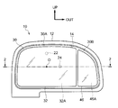
- FIG. 1 is a front view of a vehicle door mirror device 10 according to a first embodiment to which a vehicle mirror device of the present invention is applied.
- FIG. 2 shows a vehicle door mirror.
- a main part of the device 10 is shown in a sectional view (sectional view taken along line 2-2 in FIG. 1) as viewed from above.
- the front side of the vehicle is indicated by an arrow FR
- the outer side in the vehicle width direction (right side of the vehicle)
- arrow OUT the upper side is indicated by an arrow UP.
- the vehicle door mirror device 10 includes a stay (not shown) as an installation member, and the stay is an intermediate portion in the vertical direction of a vehicle door (front door, vehicle body side).
- the vehicle door mirror device 10 is installed on the door by being fixed to the front end outside.
- the stay supports a substantially rectangular parallelepiped container-like visor 12 as an accommodating member on the upper side, and the visor 12 protrudes outward in the vehicle width direction with respect to the stay.
- a substantially rectangular opening 14 is formed in the vehicle rear side wall of the visor 12, and the opening 14 opens the inside of the visor 12 to the vehicle rear side.
- an electric main unit 16 (first mirror angle adjusting device) as a first tilting mechanism shown in FIG. 2 is provided.
- a substantially hemispherical container-like case 18 as a support portion is provided at the vehicle front side portion of the main unit 16, and the inside of the case 18 is open to the vehicle rear side.
- the case 18 is supported by the visor 12, whereby the main unit 16 is supported by the visor 12.
- a substantially bottomed cylindrical tilting cylinder 20 as a first tilting portion is provided at the vehicle rear side portion of the main unit 16, and a substantially disc-shaped bottom wall is provided at the vehicle rear side end of the tilting cylinder 20. Is provided.
- the bottom wall of the tilting cylinder 20 is held by the case 18 so as to be tiltable (swinging and rotating), and the tilting cylinder 20 is tiltable with respect to the case 18 around the center O of the bottom wall.
- the diameter of the peripheral wall of the tilting cylinder 20 is gradually reduced toward the front side of the vehicle, and the peripheral wall of the tilting cylinder 20 is slidable with respect to the peripheral wall of the case 18.
- a vertical motor and an internal / external motor (not shown) as first tilting means (motor) are fixed in the case 18.
- the vertical motor and the internal / external motor have a rod-shaped vertical rod 22 as an operating member and internal and external motors, respectively.
- the rod 24 (see FIG. 1) is connected via a gear mechanism (not shown).
- the upper and lower rods 22 and the inner and outer rods 24 are held in the case 18 so as to be slidable (movable) in the vehicle front-rear direction (axial direction), and the tip end (vehicle rear side end) of the upper and lower rods 22 is the bottom of the tilting cylinder 20.
- the bottom wall of the tilting cylinder 20 is rotatably held, and the front end (vehicle rear side end) of the inner and outer rods 24 is located at the bottom wall center O of the tilting cylinder 20. It is rotatably held on the bottom wall of the tilting cylinder 20 on the outer side in the vehicle width direction (or the inner side in the vehicle width direction).
- the upper and lower motors and the inner and outer motors are electrically connected to an ECU 26 (mirror ECU, see FIG. 3A) as a control means in the visor 12 or on the vehicle body side.
- the ECU 26 includes an adjustment operation device 28 as a vehicle operation means. (See FIG. 3A) are electrically connected.
- the adjustment operation device 28 can be operated (first operation) on the main unit 16 by a vehicle occupant (especially a driver).
- the ECU 26 Under the control, the main unit 16 is operated and at least one of the vertical motor and the internal / external motor is driven, so that at least one of the vertical rod 22 and the internal / external rod 24 is slid in the vehicle longitudinal direction, and the tilt cylinder 20 is It is tilted with respect to the case 18.
- a substantially rectangular plate-like mirror holder 30 as a support member is detachably attached to the rear side of the bottom wall of the tilting cylinder 20.
- the mirror holder 30 is accommodated in the vicinity of the opening 14 in the visor 12. Yes.
- a portion of the mirror holder 30 other than the outer end in the vehicle width direction is a main holder 30A having a substantially bottomed rectangular frame shape as a first support portion, and the inside of the main holder 30A is open to the vehicle rear side. .
- a main mirror 32 having a substantially rectangular plate shape as a first mirror is held (fixed), and the mirror surface 32A (the surface of the reflective film on the back side) of the main mirror 32 is directed to the rear side of the vehicle.
- the occupant can visually recognize the rear side of the vehicle by the main mirror 32 (mirror surface 32A).
- the surface center (surface center of gravity) of the mirror surface 32A is opposed to the bottom wall center O of the tilting cylinder 20 in the vehicle front-rear direction.
- the mirror holder 30 and the main mirror 32 are tilted integrally with the tilting cylinder 20 and the mirror surface of the main mirror 32.
- the 32A angle (the direction in which the mirror surface 32A is directed) is adjusted.
- the vertical rod 22 is slid in the vehicle front-rear direction, so that the main mirror 32 is tilted in the vertical direction, and the mirror surface of the main mirror 32 The 32A angle is adjusted in the vertical direction.
- the inner / outer rod 24 is slid in the vehicle front-rear direction, whereby the main mirror 32 is tilted in the vehicle width direction, and the main mirror 32 is moved.
- the angle of the mirror surface 32A is adjusted in the vehicle width direction.
- the outer end of the mirror holder 30 in the vehicle width direction is a sub-holder 30B having a substantially bottomed rectangular frame shape as a second support portion, and the inside of the sub-holder 30B is open to the rear side of the vehicle.
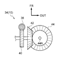
- An electric subunit 34 (second mirror surface angle adjusting device) as a second tilting mechanism shown in FIGS. 3A and 3B is provided in the sub holder 30B.
- the sub-unit 34 is provided with a sub-motor 36 as second tilting means (motor).
- the sub-motor 36 is fixed in the sub-holder 30B, and the output shaft is arranged in parallel in the vertical direction.
- An output gear 38 is coaxially fixed to the output shaft of the sub motor 36, and the output gear 38 is a worm.
- An input gear 40 is meshed with the output gear 38, and the input gear 40 is a worm wheel.
- the central axis of the input gear 40 is rotatably supported in the sub-holder 30B, and the central axis of the input gear 40 is arranged in parallel to the vehicle width direction.
- a transmission gear 42 is coaxially fixed to the central axis of the input gear 40, and the transmission gear 42 is a bevel gear.
- An operating gear 44 is engaged with the transmission gear 42, and the operating gear 44 is a bevel gear.
- a central axis 44A as a second tilting portion of the operating gear 44 is rotatably supported in the sub-holder 30B, and the central axis 44A of the operating gear 44 is arranged in parallel in the vertical direction.
- the sub motor 36 is electrically connected to the ECU 26.
- the adjustment operation device 28 can be operated (second operation) with respect to the subunit 34 by an occupant.
- the subunit 34 is controlled by the ECU 26.
- the sub motor 36 is driven to rotate the output gear 38, the input gear 40, the transmission gear 42, and the operating gear 44, and the central shaft 44A of the operating gear 44 is rotated.
- a substantially rectangular plate-shaped sub mirror 46 as a second mirror is fixed to the central shaft 44A of the operating gear 44 on the rear side of the vehicle, and the mirror surface 46A (back side) of the sub mirror 46 is fixed.
- the surface of the reflective film is directed to the rear side of the vehicle, so that the occupant can visually recognize the rear side of the vehicle by the sub mirror 46 (mirror surface 46A).
- the center of the mirror surface 46A (surface center of gravity) is opposed to the central axis 44A of the transmission gear 42 in the vehicle front-rear direction.
- the sub-mirror 46 is tilted integrally with the central shaft 44A of the operating gear 44 in the vehicle width direction.
- the mirror surface 46A angle (the direction in which the mirror surface 46A is directed) is adjusted in the vehicle width direction.
- a detection device 48 as a detection means is electrically connected to the ECU 26, and the detection device 48 is a dangerous object (others in the vehicle width direction on the side of the vehicle door mirror device 10). Vehicle etc.) can be detected.
- the main unit 16 when the adjustment operation device 28 is operated on the main unit 16, the main unit 16 is operated under the control of the ECU 26, and at least one of the vertical motor and the internal / external motor is driven. As a result, at least one of the upper and lower rods 22 and the inner and outer rods 24 is slid in the vehicle longitudinal direction. For this reason, the tilting cylinder 20, the mirror holder 30, and the main mirror 32 are tilted with respect to the case 18 in at least one of the vertical direction and the vehicle width direction, and the main mirror 32 is tilted to the normal position. The angle of the mirror surface 32A is adjusted, and the viewing range of the occupant's main mirror 32 is adjusted.
- the subunit 34 When the adjustment operation device 28 is operated on the subunit 34, the subunit 34 is operated and the sub motor 36 is driven under the control of the ECU 26, whereby the output gear 38, the input gear 40, and the transmission are transmitted.
- the gear 42 and the operating gear 44 are rotated. Therefore, the sub mirror 46 is tilted integrally with the central shaft 44A of the operating gear 44 in the vehicle width direction, and the sub mirror 46 is tilted to the normal position, whereby the angle of the mirror surface 46A of the sub mirror 46 is adjusted and the passenger's sub mirror is adjusted.
- the viewing range by 46 is adjusted.
- the main unit 16 is operated under the control of the ECU 26 to drive the inner and outer motors.
- the inner and outer rods 24 are slid forward of the vehicle, and the tilting cylinder 20, the mirror holder 30 and the main mirror 32 are tilted outward in the vehicle width direction with respect to the case 18.
- the sub unit 34 is operated and the sub motor 36 is driven by the control of the ECU 26, whereby the operating gear 44 is rotated and the sub mirror 46 is integrated with the central shaft 44 ⁇ / b> A of the operating gear 44. Tilt outward in the vehicle width direction.
- the main mirror 32 (including the mirror holder 30) and the sub mirror 46 are tilted to the change position, the mirror surface 32A of the main mirror 32 is directed outward in the vehicle width direction, and the mirror surface 46A of the sub mirror 46 is outward in the vehicle width direction.
- the occupant can visually recognize the dangerous object by the sub mirror 46 (the dangerous object may also be visually recognized by the main mirror 32).
- the main unit 16 is operated under the control of the ECU 26 and the internal / external motor is driven, so that the internal / external rod 24 is slid rearward of the vehicle,
- the tilt cylinder 20, the mirror holder 30 and the main mirror 32 are tilted inward in the vehicle width direction with respect to the case 18.
- the sub unit 34 is operated and the sub motor 36 is driven by the control of the ECU 26, whereby the operating gear 44 is rotated and the sub mirror 46 is integrated with the central shaft 44 ⁇ / b> A of the operating gear 44. Tilt inward in the vehicle width direction. Therefore, the main mirror 32 and the sub mirror 46 are tilted (returned) to the normal position.
- the main unit 16 supports the subunit 34 via the mirror holder 30, and the subunit 34 supports the sub mirror 46. Therefore, the main unit 16 is actuated and the sub mirror 46 is tilted via the mirror holder 30 and the sub unit 34. At the same time, the sub unit 34 is actuated and the sub mirror 46 is tilted, so that the tilt speed of the sub mirror 46 is increased. And the adjustment speed of the mirror surface 46A angle of the sub mirror 46 can be increased.
- the detection device 48 detects a dangerous substance
- the main unit 16 is operated and the sub mirror 46 is tilted outward in the vehicle width direction
- the sub unit 34 is operated and the sub mirror 46 is moved outward in the vehicle width direction. Tilt to.
- the sub mirror 46 can be tilted to the change position at high speed, and the occupant can visually recognize the dangerous object at an early stage by the sub mirror 46.
- the main unit 16 is operated and the sub mirror 46 is tilted inward in the vehicle width direction, and at the same time, the sub unit 34 is operated and the sub mirror 46 is moved. Tilt inward in the vehicle width direction. Thereby, the sub mirror 46 can be tilted to the normal position at high speed, and the sub mirror 46 can be returned to the normal position at an early stage.
- FIG. 4 is a cross-sectional view (a cross-sectional view taken along line 2-2 in FIG. 1) of the main part of the vehicle door mirror device 60 according to the second embodiment to which the vehicle mirror device of the present invention is applied. Is shown.
- the vehicle door mirror device 60 according to the present embodiment has substantially the same configuration as the first embodiment, but differs in the following points.
- the main holder 30A and the sub-holder 30B of the mirror holder 30 are separated.
- the main holder 30A is enlarged outward in the vehicle width direction
- the main mirror 32 is enlarged outward in the vehicle width direction together with the main holder 30A.
- the sub holder 30 ⁇ / b> B is fixed to the vehicle rear side (front side) of the outer end in the vehicle width direction of the main mirror 32, and the sub mirror 46 is disposed on the vehicle rear side of the main mirror 32.
- a sub mirror 46 is arranged on the vehicle rear side of the main mirror 32. For this reason, it can suppress that the submirror 46 penetrate
- the sub mirror 46 is greatly intruded into the vehicle front side from the opening 14 in the visor 12. It is possible to suppress the visual recognition of dangerous objects by the passenger's sub-mirror 46 from being restricted to the peripheral wall around the opening 14 of the visor 12.
- FIG. 5 is a front view of a vehicle door mirror device 70 according to a third embodiment to which the vehicle mirror device of the present invention is applied as viewed from the rear of the vehicle.
- the vehicle door mirror device 70 according to the present embodiment has substantially the same configuration as that of the first embodiment, but differs in the following points.
- the upper portion of the main holder 30A of the mirror holder 30 is enlarged outward in the vehicle width direction, and the upper portion of the main mirror 32 is the main holder. It is enlarged to the outside in the vehicle width direction along with 30A.
- the sub-holder 30B of the mirror holder 30 is provided at the lower part of the outer end of the mirror holder 30 in the vehicle width direction, and the sub-mirror 46 is arranged in the sub-holder 30B with a reduced vertical dimension.
- the mirror holder 30, the main mirror 32, and the sub mirror 46 are changed in the first embodiment.
- FIG. 6A The main part of the vehicle door mirror device 80 according to the fourth embodiment to which the vehicle mirror device of the present invention is applied is shown in FIG. 6A as a front view, and FIG. The main part of the vehicle door mirror device 80 is shown in a plan view as viewed from above.
- the vehicle door mirror device 80 according to the present embodiment has substantially the same configuration as the first embodiment, but differs in the following points.
- the transmission gear 42 is a worm and the operation gear 44 is a worm wheel in the subunit 34.
- the transmission gear 42 and the operating gear 44 are changed in the first embodiment.
- the transmission gear 42 and the operating gear 44 may be changed similarly to the present embodiment.
- the sub mirror 46 (main holder 30A) is disposed outside the main mirror 32 (main holder 30A) in the vehicle width direction.
- the sub mirror 46 (main holder 30A) may be disposed on a side other than the outer side in the vehicle width direction of the main mirror 32 (main holder 30A) (for example, the upper side, the lower side, or the inner side in the vehicle width direction).
- the sub mirror 46 can be tilted in the vehicle width direction.
- the sub mirror 46 may be tilted in at least one of the vertical direction and the vehicle width direction.
- the tilt center of the sub mirror 46 (the center axis 44A of the transmission gear 42) is opposed to the center of the mirror surface 46A of the sub mirror 46 in the vehicle front-rear direction.
- the tilt center of the sub mirror 46 may be arranged on one side of the surface center of the mirror surface 46A of the sub mirror 46.
- the center of tilting of the sub-mirror 46 (the center axis 44A of the transmission gear 42) is arranged on the outer side in the vehicle width direction of the center of the mirror surface 46A of the sub-mirror 46, so that the sub-mirror 46 is tilted outward in the vehicle width direction.
- the visual recognition range by 46 can be greatly changed to the outside in the vehicle width direction, and the arrangement range of dangerous objects that can be visually recognized by the occupant by the sub mirror 46 can be widened.
- the main mirror 32 and the sub mirror 46 when the detection device 48 detects a dangerous substance, the main mirror 32 and the sub mirror 46 are tilted outward in the vehicle width direction under the control of the ECU 26.
- the main mirror 32 and the sub mirror 46 may be tilted in at least one of the vertical direction and the vehicle width direction under the control of the ECU 26.
- the vehicle direction indicator operation device
- the main mirror 32 and the sub mirror 46 may be tilted outward in the vehicle width direction under the control of the ECU 26.
- the shift range of the automatic transmission of the vehicle is changed to the reverse range, the main mirror 32 and the sub mirror 46 may be tilted downward by the control of the ECU 26.
- the center of tilting of the sub mirror 46 (the center axis 44A of the transmission gear 42) is used as the operating position of the main mirror 32 by the main unit 16 (the tilting cylinders of the upper and lower rods 22 and the inner and outer rods 24). It is arranged on the outer side in the vehicle width direction) at the connection position with the 20 bottom wall.
- the main unit 16 connecting position with the bottom wall of at least one of the upper and lower rods 22 and the inner and outer rods 24
- the positions may be matched.
- the sub mirror 46 can be effectively supported by at least one of the upper and lower rods 22 and the inner and outer rods 24, and the crack of the sub mirror 46 can be effectively suppressed when the vehicle is traveling.
- the present invention is applied to the vehicle door mirror device 10, 60, 70, 80.
- the present invention may be applied to other outside or inside mirror devices.
- Vehicle door mirror device (vehicle mirror device) 16 Main unit (first tilt mechanism) 32 Main mirror (first mirror) 32A mirror surface 34 subunit (second tilting mechanism) 46 Sub mirror (second mirror) 46A Mirror surface
Abstract
In a vehicular door mirror device (10), a main unit (16) supports a sub-unit (34) via a mirror holder (30), and the sub-unit (34) supports a sub-mirror (46). Thus, by activating the main unit (16) to tilt the sub-mirror (46) via the mirror holder (30) and the sub-unit (34) and simultaneously activating the sub-unit (34) to tilt the sub-mirror (46), the tilting speed of the sub-mirror (46) can be increased.
Description
本発明は、車両に設けられる第1ミラー及び第2ミラーを傾動させる車両用ミラー装置に関する。
The present invention relates to a vehicle mirror device that tilts a first mirror and a second mirror provided in a vehicle.
中国実用新案公告第202163359号明細書に記載された後方視認ミラーでは、第1駆動機構が第1ミラーを傾動させると共に、第2駆動機構が第2ミラーを傾動させる。
In the rear view mirror described in the Chinese Utility Model Publication No. 202163359, the first drive mechanism tilts the first mirror and the second drive mechanism tilts the second mirror.
ところで、この後方視認ミラーでは、第1駆動機構と第2駆動機構とが別々に鏡殻に支持されている。
Incidentally, in this rear view mirror, the first drive mechanism and the second drive mechanism are separately supported by the mirror shell.
ここで、このような後方視認ミラーでは、例えば第2ミラーの傾動速度を大きくできるのが好ましい。
Here, in such a rear view mirror, for example, it is preferable that the tilting speed of the second mirror can be increased.
本発明は、上記事実を考慮し、第2ミラーの傾動速度を大きくできる車両用ミラー装置を得ることが目的である。
The present invention is intended to obtain a vehicle mirror device that can increase the tilting speed of the second mirror in consideration of the above facts.
本発明の第1態様の車両用ミラー装置は、車両に設けられる第1ミラーと、前記第1ミラーを支持し、前記第1ミラーを傾動させることで前記第1ミラーの鏡面角度が調整される第1傾動機構と、車両に設けられる第2ミラーと、前記第1傾動機構が支持すると共に、前記第2ミラーを支持し、前記第1傾動機構が前記第2ミラーを傾動させることで前記第2ミラーの鏡面角度が調整されると共に、前記第2ミラーを傾動させることで前記第2ミラーの鏡面角度が調整される第2傾動機構と、を備えている。
The vehicle mirror device according to the first aspect of the present invention supports a first mirror provided in a vehicle, the first mirror, and tilts the first mirror to adjust a mirror surface angle of the first mirror. The first tilting mechanism, the second mirror provided on the vehicle, the first tilting mechanism supports the second mirror, and the first tilting mechanism tilts the second mirror to support the first mirror. And a second tilting mechanism for adjusting the mirror surface angle of the second mirror by tilting the second mirror.
本発明の第1態様の車両用ミラー装置では、第1傾動機構が第1ミラーを支持しており、第1傾動機構が第1ミラーを傾動させることで、ミラーの鏡面角度が調整される。さらに、第2傾動機構が第2ミラーを支持しており、第2傾動機構が第2ミラーを傾動させることで、第2ミラーの鏡面角度が調整される。
In the vehicle mirror device according to the first aspect of the present invention, the first tilting mechanism supports the first mirror, and the first tilting mechanism tilts the first mirror so that the mirror surface angle of the mirror is adjusted. Furthermore, the second tilting mechanism supports the second mirror, and the second tilting mechanism tilts the second mirror, so that the mirror surface angle of the second mirror is adjusted.
ここで、第1傾動機構が第2傾動機構を支持しており、第1傾動機構が第2ミラーを傾動させることで、第2ミラーの鏡面角度が調整される。このため、第1傾動機構が第2ミラーを傾動させると共に、第2傾動機構が第2ミラーを傾動させることで、第2ミラーの傾動速度を大きくできる。
Here, the first tilting mechanism supports the second tilting mechanism, and the mirror angle of the second mirror is adjusted by the first tilting mechanism tilting the second mirror. For this reason, the first tilting mechanism tilts the second mirror, and the second tilting mechanism tilts the second mirror, whereby the tilting speed of the second mirror can be increased.
本発明の第2態様の車両用ミラー装置は、本発明の第1態様の車両用ミラー装置において、前記第2ミラーの鏡面中心の一側に前記第2ミラーの傾動中心を配置している。
The vehicle mirror device according to the second aspect of the present invention is the vehicle mirror device according to the first aspect of the present invention, wherein the tilt center of the second mirror is disposed on one side of the mirror surface center of the second mirror.
本発明の第2態様の車両用ミラー装置では、第2ミラーの鏡面中心の一側に第2ミラーの傾動中心が配置されている。このため、第2ミラーの傾動によって第2ミラーによる視認範囲を一側に大きく変更できる。
In the vehicle mirror device according to the second aspect of the present invention, the tilt center of the second mirror is disposed on one side of the mirror surface center of the second mirror. For this reason, the visual recognition range by the second mirror can be largely changed to one side by tilting the second mirror.
本発明の第3態様の車両用ミラー装置は、本発明の第1態様又は第2態様の車両用ミラー装置において、前記第2ミラーを前記第1ミラーの表側に配置している。
The vehicle mirror device according to the third aspect of the present invention is the vehicle mirror device according to the first aspect or the second aspect of the present invention, wherein the second mirror is arranged on the front side of the first mirror.
本発明の第3態様の車両用ミラー装置では、第2ミラーが第1ミラーの表側に配置されている。このため、第2ミラーによる視認が制限されることを抑制可能にできる。
In the vehicle mirror device according to the third aspect of the present invention, the second mirror is arranged on the front side of the first mirror. For this reason, it can suppress that the visual recognition by a 2nd mirror is restrict | limited.
本発明の第4態様の車両用ミラー装置は、本発明の第1態様~第3態様の何れか1つの車両用ミラー装置において、前記第1傾動機構による前記第1ミラーの作動位置と前記第2ミラーの傾動中心との水平方向位置を一致させる。
The vehicle mirror device according to a fourth aspect of the present invention is the vehicle mirror device according to any one of the first to third aspects of the present invention, wherein the operating position of the first mirror by the first tilting mechanism and the first mirror mechanism are the same. The horizontal position with the tilt center of the two mirrors is matched.
本発明の第4態様の車両用ミラー装置では、第1傾動機構による第1ミラーの作動位置と第2ミラーの傾動中心との水平方向位置が一致される。このため、第2ミラーのびびりを効果的に抑制できる。
In the vehicle mirror device according to the fourth aspect of the present invention, the horizontal position of the operating position of the first mirror by the first tilting mechanism and the tilting center of the second mirror are matched. For this reason, chattering of the second mirror can be effectively suppressed.
[第1実施形態]
[First embodiment]
図1には、本発明の車両用ミラー装置が適用された第1実施形態に係る車両用ドアミラー装置10が車両後方から見た正面図にて示されており、図2には、車両用ドアミラー装置10の主要部が上方から見た断面図(図1の2-2線断面図)にて示されている。なお、図面では、車両前方を矢印FRで示し、車幅方向外方(車両右方)を矢印OUTで示し、上方を矢印UPで示している。
FIG. 1 is a front view of a vehicle door mirror device 10 according to a first embodiment to which a vehicle mirror device of the present invention is applied. FIG. 2 shows a vehicle door mirror. A main part of the device 10 is shown in a sectional view (sectional view taken along line 2-2 in FIG. 1) as viewed from above. In the drawing, the front side of the vehicle is indicated by an arrow FR, the outer side in the vehicle width direction (right side of the vehicle) is indicated by an arrow OUT, and the upper side is indicated by an arrow UP.
図1に示す如く、本実施形態に係る車両用ドアミラー装置10は、設置部材としてのステー(図示省略)を備えており、ステーが車両のドア(フロントドア、車体側)の上下方向中間部の前端外側に固定されることで、車両用ドアミラー装置10がドアに設置されている。ステーは、上側において、収容部材としての略直方体形容器状のバイザ12を支持しており、バイザ12は、ステーに対し車幅方向外側に突出されている。バイザ12の車両後側壁には、略矩形状の開口14が形成されており、開口14は、バイザ12内を車両後側に開放させている。
As shown in FIG. 1, the vehicle door mirror device 10 according to the present embodiment includes a stay (not shown) as an installation member, and the stay is an intermediate portion in the vertical direction of a vehicle door (front door, vehicle body side). The vehicle door mirror device 10 is installed on the door by being fixed to the front end outside. The stay supports a substantially rectangular parallelepiped container-like visor 12 as an accommodating member on the upper side, and the visor 12 protrudes outward in the vehicle width direction with respect to the stay. A substantially rectangular opening 14 is formed in the vehicle rear side wall of the visor 12, and the opening 14 opens the inside of the visor 12 to the vehicle rear side.
バイザ12内には、図2に示す第1傾動機構としての電動式のメインユニット16(第1鏡面角度調整装置)が設けられている。
In the visor 12, an electric main unit 16 (first mirror angle adjusting device) as a first tilting mechanism shown in FIG. 2 is provided.
メインユニット16の車両前側部分には、支持部としての略半球形容器状のケース18が設けられており、ケース18内は、車両後側に開放されている。ケース18は、バイザ12に支持されており、これにより、メインユニット16がバイザ12に支持されている。
A substantially hemispherical container-like case 18 as a support portion is provided at the vehicle front side portion of the main unit 16, and the inside of the case 18 is open to the vehicle rear side. The case 18 is supported by the visor 12, whereby the main unit 16 is supported by the visor 12.
メインユニット16の車両後側部分には、第1傾動部としての略有底円筒状の傾動筒20が設けられており、傾動筒20の車両後側端には、略円板状の底壁が設けられている。傾動筒20の底壁は、ケース18に傾動(揺動、回動)可能に保持されており、傾動筒20は、底壁の中心Oを中心としてケース18に対し傾動可能にされている。傾動筒20の周壁は、車両前側へ向かうに従い径が徐々に小さくされており、傾動筒20の周壁は、ケース18の周壁に対し摺動可能にされている。
A substantially bottomed cylindrical tilting cylinder 20 as a first tilting portion is provided at the vehicle rear side portion of the main unit 16, and a substantially disc-shaped bottom wall is provided at the vehicle rear side end of the tilting cylinder 20. Is provided. The bottom wall of the tilting cylinder 20 is held by the case 18 so as to be tiltable (swinging and rotating), and the tilting cylinder 20 is tiltable with respect to the case 18 around the center O of the bottom wall. The diameter of the peripheral wall of the tilting cylinder 20 is gradually reduced toward the front side of the vehicle, and the peripheral wall of the tilting cylinder 20 is slidable with respect to the peripheral wall of the case 18.
ケース18内には、第1傾動手段(モータ)としての上下モータ及び内外モータ(図示省略)が固定されており、上下モータ及び内外モータには、それぞれ作動部材としての棒状の上下ロッド22及び内外ロッド24(図1参照)がギア機構(図示省略)を介して接続されている。上下ロッド22及び内外ロッド24は、ケース18内に車両前後方向(軸方向)へスライド(移動)可能に保持されており、上下ロッド22の先端(車両後側端)は、傾動筒20の底壁中心Oの上方(下方でもよい)において、傾動筒20の底壁に回動可能に保持されると共に、内外ロッド24の先端(車両後側端)は、傾動筒20の底壁中心Oの車幅方向外方(車幅方向内方でもよい)において、傾動筒20の底壁に回動可能に保持されている。
A vertical motor and an internal / external motor (not shown) as first tilting means (motor) are fixed in the case 18. The vertical motor and the internal / external motor have a rod-shaped vertical rod 22 as an operating member and internal and external motors, respectively. The rod 24 (see FIG. 1) is connected via a gear mechanism (not shown). The upper and lower rods 22 and the inner and outer rods 24 are held in the case 18 so as to be slidable (movable) in the vehicle front-rear direction (axial direction), and the tip end (vehicle rear side end) of the upper and lower rods 22 is the bottom of the tilting cylinder 20. Above the wall center O (which may be below), the bottom wall of the tilting cylinder 20 is rotatably held, and the front end (vehicle rear side end) of the inner and outer rods 24 is located at the bottom wall center O of the tilting cylinder 20. It is rotatably held on the bottom wall of the tilting cylinder 20 on the outer side in the vehicle width direction (or the inner side in the vehicle width direction).
上下モータ及び内外モータは、バイザ12内又は車体側の制御手段としてのECU26(ミラーECU、図3A参照)に電気的に接続されており、ECU26には、車両の操作手段としての調整操作装置28(図3A参照)が電気的に接続されている。調整操作装置28は、車両の乗員(特に運転手)によりメインユニット16に対する操作(第1操作)を可能にされており、調整操作装置28がメインユニット16に対する操作をされた際には、ECU26の制御により、メインユニット16が作動されて、上下モータ及び内外モータの少なくとも一方が駆動されることで、上下ロッド22及び内外ロッド24の少なくとも一方が車両前後方向へスライドされて、傾動筒20がケース18に対し傾動される。
The upper and lower motors and the inner and outer motors are electrically connected to an ECU 26 (mirror ECU, see FIG. 3A) as a control means in the visor 12 or on the vehicle body side. The ECU 26 includes an adjustment operation device 28 as a vehicle operation means. (See FIG. 3A) are electrically connected. The adjustment operation device 28 can be operated (first operation) on the main unit 16 by a vehicle occupant (especially a driver). When the adjustment operation device 28 is operated on the main unit 16, the ECU 26 Under the control, the main unit 16 is operated and at least one of the vertical motor and the internal / external motor is driven, so that at least one of the vertical rod 22 and the internal / external rod 24 is slid in the vehicle longitudinal direction, and the tilt cylinder 20 is It is tilted with respect to the case 18.
傾動筒20の底壁の車両後側には、支持部材としての略矩形板状のミラーホルダ30が着脱可能に装着されており、ミラーホルダ30は、バイザ12内の開口14近傍に収容されている。
A substantially rectangular plate-like mirror holder 30 as a support member is detachably attached to the rear side of the bottom wall of the tilting cylinder 20. The mirror holder 30 is accommodated in the vicinity of the opening 14 in the visor 12. Yes.
ミラーホルダ30の車幅方向外側端部以外の部分は、第1支持部としての略有底矩形枠状のメインホルダ30Aにされており、メインホルダ30A内は、車両後側に開放されている。メインホルダ30A内には、第1ミラーとしての略矩形板状のメインミラー32が保持(固定)されており、メインミラー32の鏡面32A(裏側の反射膜の表面)が車両後側に向けられることで、乗員がメインミラー32(鏡面32A)によって車両後側を視認可能にされている。また、鏡面32Aの面中心(面重心)は、傾動筒20の底壁中心Oに車両前後方向において対向されている。
A portion of the mirror holder 30 other than the outer end in the vehicle width direction is a main holder 30A having a substantially bottomed rectangular frame shape as a first support portion, and the inside of the main holder 30A is open to the vehicle rear side. . In the main holder 30A, a main mirror 32 having a substantially rectangular plate shape as a first mirror is held (fixed), and the mirror surface 32A (the surface of the reflective film on the back side) of the main mirror 32 is directed to the rear side of the vehicle. Thus, the occupant can visually recognize the rear side of the vehicle by the main mirror 32 (mirror surface 32A). Further, the surface center (surface center of gravity) of the mirror surface 32A is opposed to the bottom wall center O of the tilting cylinder 20 in the vehicle front-rear direction.
上述の如く、メインユニット16が作動されて、傾動筒20がケース18に対し傾動される際には、ミラーホルダ30及びメインミラー32が傾動筒20と一体に傾動されて、メインミラー32の鏡面32A角度(鏡面32Aが向けられる方向)が調整される。また、メインユニット16が作動されて、上下モータが駆動される際には、上下ロッド22が車両前後方向へスライドされることで、メインミラー32が上下方向において傾動されて、メインミラー32の鏡面32A角度が上下方向において調整される。さらに、メインユニット16が作動されて、内外モータが駆動される際には、内外ロッド24が車両前後方向へスライドされることで、メインミラー32が車幅方向において傾動されて、メインミラー32の鏡面32A角度が車幅方向において調整される。
As described above, when the main unit 16 is operated and the tilting cylinder 20 is tilted with respect to the case 18, the mirror holder 30 and the main mirror 32 are tilted integrally with the tilting cylinder 20 and the mirror surface of the main mirror 32. The 32A angle (the direction in which the mirror surface 32A is directed) is adjusted. Further, when the main unit 16 is operated and the vertical motor is driven, the vertical rod 22 is slid in the vehicle front-rear direction, so that the main mirror 32 is tilted in the vertical direction, and the mirror surface of the main mirror 32 The 32A angle is adjusted in the vertical direction. Further, when the main unit 16 is operated to drive the inner / outer motor, the inner / outer rod 24 is slid in the vehicle front-rear direction, whereby the main mirror 32 is tilted in the vehicle width direction, and the main mirror 32 is moved. The angle of the mirror surface 32A is adjusted in the vehicle width direction.
ミラーホルダ30の車幅方向外側端部は、第2支持部としての略有底矩形枠状のサブホルダ30Bにされており、サブホルダ30B内は、車両後側に開放されている。サブホルダ30B内には、図3A及び図3Bに示す第2傾動機構としての電動式のサブユニット34(第2鏡面角度調整装置)が設けられている。
The outer end of the mirror holder 30 in the vehicle width direction is a sub-holder 30B having a substantially bottomed rectangular frame shape as a second support portion, and the inside of the sub-holder 30B is open to the rear side of the vehicle. An electric subunit 34 (second mirror surface angle adjusting device) as a second tilting mechanism shown in FIGS. 3A and 3B is provided in the sub holder 30B.
サブユニット34には、第2傾動手段(モータ)としてのサブモータ36が設けられており、サブモータ36は、サブホルダ30B内に固定されると共に、出力軸が上下方向に平行に配置されている。サブモータ36の出力軸には、出力ギア38が同軸上に固定されており、出力ギア38は、ウォームにされている。出力ギア38には、入力ギア40が噛合されており、入力ギア40は、ウォームホイールにされている。入力ギア40の中心軸は、サブホルダ30B内に回転可能に支持されており、入力ギア40の中心軸は、車幅方向に平行に配置されている。入力ギア40の中心軸には、伝達ギア42が同軸上に固定されており、伝達ギア42は、かさ歯車にされている。伝達ギア42には、作動ギア44が噛合されており、作動ギア44は、かさ歯車にされている。作動ギア44の第2傾動部としての中心軸44Aは、サブホルダ30B内に回転可能に支持されており、作動ギア44の中心軸44Aは、上下方向に平行に配置されている。
The sub-unit 34 is provided with a sub-motor 36 as second tilting means (motor). The sub-motor 36 is fixed in the sub-holder 30B, and the output shaft is arranged in parallel in the vertical direction. An output gear 38 is coaxially fixed to the output shaft of the sub motor 36, and the output gear 38 is a worm. An input gear 40 is meshed with the output gear 38, and the input gear 40 is a worm wheel. The central axis of the input gear 40 is rotatably supported in the sub-holder 30B, and the central axis of the input gear 40 is arranged in parallel to the vehicle width direction. A transmission gear 42 is coaxially fixed to the central axis of the input gear 40, and the transmission gear 42 is a bevel gear. An operating gear 44 is engaged with the transmission gear 42, and the operating gear 44 is a bevel gear. A central axis 44A as a second tilting portion of the operating gear 44 is rotatably supported in the sub-holder 30B, and the central axis 44A of the operating gear 44 is arranged in parallel in the vertical direction.
サブモータ36は、ECU26に電気的に接続されている。調整操作装置28は、乗員によりサブユニット34に対する操作(第2操作)を可能にされており、調整操作装置28がサブユニット34に対する操作をされた際には、ECU26の制御により、サブユニット34が作動されて、サブモータ36が駆動されることで、出力ギア38、入力ギア40、伝達ギア42及び作動ギア44が回転されて、作動ギア44の中心軸44Aが回転される。
The sub motor 36 is electrically connected to the ECU 26. The adjustment operation device 28 can be operated (second operation) with respect to the subunit 34 by an occupant. When the adjustment operation device 28 is operated with respect to the subunit 34, the subunit 34 is controlled by the ECU 26. And the sub motor 36 is driven to rotate the output gear 38, the input gear 40, the transmission gear 42, and the operating gear 44, and the central shaft 44A of the operating gear 44 is rotated.
図2に示す如く、作動ギア44の中心軸44Aには、車両後側において、第2ミラーとしての略矩形板状のサブミラー46(補助ミラー)が固定されており、サブミラー46の鏡面46A(裏側の反射膜の表面)が車両後側に向けられることで、乗員がサブミラー46(鏡面46A)によって車両後側を視認可能にされている。また、鏡面46Aの面中心(面重心)は、伝達ギア42の中心軸44Aに車両前後方向において対向されている。
As shown in FIG. 2, a substantially rectangular plate-shaped sub mirror 46 (auxiliary mirror) as a second mirror is fixed to the central shaft 44A of the operating gear 44 on the rear side of the vehicle, and the mirror surface 46A (back side) of the sub mirror 46 is fixed. The surface of the reflective film) is directed to the rear side of the vehicle, so that the occupant can visually recognize the rear side of the vehicle by the sub mirror 46 (mirror surface 46A). Further, the center of the mirror surface 46A (surface center of gravity) is opposed to the central axis 44A of the transmission gear 42 in the vehicle front-rear direction.
上述の如く、サブユニット34が作動されて、作動ギア44の中心軸44Aが回転される際には、サブミラー46が作動ギア44の中心軸44Aと一体に車幅方向において傾動されて、サブミラー46の鏡面46A角度(鏡面46Aが向けられる方向)が車幅方向において調整される。
As described above, when the sub-unit 34 is operated and the central shaft 44A of the operating gear 44 is rotated, the sub-mirror 46 is tilted integrally with the central shaft 44A of the operating gear 44 in the vehicle width direction. The mirror surface 46A angle (the direction in which the mirror surface 46A is directed) is adjusted in the vehicle width direction.
図3Aに示す如く、ECU26には、検知手段としての検知装置48が電気的に接続されており、検知装置48は、車両の車両用ドアミラー装置10側における車幅方向外側の危険物(他の車両等)を検知可能にされている。
As shown in FIG. 3A, a detection device 48 as a detection means is electrically connected to the ECU 26, and the detection device 48 is a dangerous object (others in the vehicle width direction on the side of the vehicle door mirror device 10). Vehicle etc.) can be detected.
次に、本実施形態の作用を説明する。
Next, the operation of this embodiment will be described.
以上の構成の車両用ドアミラー装置10では、調整操作装置28がメインユニット16に対する操作をされた際に、ECU26の制御により、メインユニット16が作動されて、上下モータ及び内外モータの少なくとも一方が駆動されることで、上下ロッド22及び内外ロッド24の少なくとも一方が車両前後方向へスライドされる。このため、傾動筒20、ミラーホルダ30及びメインミラー32がケース18に対し上下方向及び車幅方向の少なくとも一方において傾動されて、メインミラー32が通常位置に傾動されることで、メインミラー32の鏡面32A角度が調整されて、乗員のメインミラー32による視認範囲が調整される。
In the vehicle door mirror device 10 having the above configuration, when the adjustment operation device 28 is operated on the main unit 16, the main unit 16 is operated under the control of the ECU 26, and at least one of the vertical motor and the internal / external motor is driven. As a result, at least one of the upper and lower rods 22 and the inner and outer rods 24 is slid in the vehicle longitudinal direction. For this reason, the tilting cylinder 20, the mirror holder 30, and the main mirror 32 are tilted with respect to the case 18 in at least one of the vertical direction and the vehicle width direction, and the main mirror 32 is tilted to the normal position. The angle of the mirror surface 32A is adjusted, and the viewing range of the occupant's main mirror 32 is adjusted.
また、調整操作装置28がサブユニット34に対する操作をされた際には、ECU26の制御により、サブユニット34が作動されて、サブモータ36が駆動されることで、出力ギア38、入力ギア40、伝達ギア42及び作動ギア44が回転される。このため、サブミラー46が作動ギア44の中心軸44Aと一体に車幅方向において傾動されて、サブミラー46が通常位置に傾動されることで、サブミラー46の鏡面46A角度が調整されて、乗員のサブミラー46による視認範囲が調整される。
When the adjustment operation device 28 is operated on the subunit 34, the subunit 34 is operated and the sub motor 36 is driven under the control of the ECU 26, whereby the output gear 38, the input gear 40, and the transmission are transmitted. The gear 42 and the operating gear 44 are rotated. Therefore, the sub mirror 46 is tilted integrally with the central shaft 44A of the operating gear 44 in the vehicle width direction, and the sub mirror 46 is tilted to the normal position, whereby the angle of the mirror surface 46A of the sub mirror 46 is adjusted and the passenger's sub mirror is adjusted. The viewing range by 46 is adjusted.
検知装置48が車両の車両用ドアミラー装置10側における車幅方向外側の危険物を検知した際(所定の機会)には、ECU26の制御により、メインユニット16が作動されて、内外モータが駆動されることで、内外ロッド24が車両前方へスライドされて、傾動筒20、ミラーホルダ30及びメインミラー32がケース18に対し車幅方向外側に傾動される。しかも、この際には、ECU26の制御により、サブユニット34が作動されて、サブモータ36が駆動されることで、作動ギア44が回転されて、サブミラー46が作動ギア44の中心軸44Aと一体に車幅方向外側に傾動される。このため、メインミラー32(ミラーホルダ30を含む)及びサブミラー46が変更位置に傾動されて、メインミラー32の鏡面32Aが車幅方向外側に向けられると共に、サブミラー46の鏡面46Aが車幅方向外側に向けられることで、乗員がサブミラー46によって危険物を視認できる(メインミラー32によっても危険物を視認できてもよい)。
When the detection device 48 detects a dangerous substance outside the vehicle width direction on the vehicle door mirror device 10 side of the vehicle (predetermined opportunity), the main unit 16 is operated under the control of the ECU 26 to drive the inner and outer motors. Thus, the inner and outer rods 24 are slid forward of the vehicle, and the tilting cylinder 20, the mirror holder 30 and the main mirror 32 are tilted outward in the vehicle width direction with respect to the case 18. In addition, at this time, the sub unit 34 is operated and the sub motor 36 is driven by the control of the ECU 26, whereby the operating gear 44 is rotated and the sub mirror 46 is integrated with the central shaft 44 </ b> A of the operating gear 44. Tilt outward in the vehicle width direction. Therefore, the main mirror 32 (including the mirror holder 30) and the sub mirror 46 are tilted to the change position, the mirror surface 32A of the main mirror 32 is directed outward in the vehicle width direction, and the mirror surface 46A of the sub mirror 46 is outward in the vehicle width direction. The occupant can visually recognize the dangerous object by the sub mirror 46 (the dangerous object may also be visually recognized by the main mirror 32).
その後、検知装置48が危険物を検知しなくなった際には、ECU26の制御により、メインユニット16が作動されて、内外モータが駆動されることで、内外ロッド24が車両後方へスライドされて、傾動筒20、ミラーホルダ30及びメインミラー32がケース18に対し車幅方向内側に傾動される。しかも、この際には、ECU26の制御により、サブユニット34が作動されて、サブモータ36が駆動されることで、作動ギア44が回転されて、サブミラー46が作動ギア44の中心軸44Aと一体に車幅方向内側に傾動される。このため、メインミラー32及びサブミラー46が通常位置に傾動(復帰)される。
Thereafter, when the detection device 48 no longer detects a dangerous substance, the main unit 16 is operated under the control of the ECU 26 and the internal / external motor is driven, so that the internal / external rod 24 is slid rearward of the vehicle, The tilt cylinder 20, the mirror holder 30 and the main mirror 32 are tilted inward in the vehicle width direction with respect to the case 18. In addition, at this time, the sub unit 34 is operated and the sub motor 36 is driven by the control of the ECU 26, whereby the operating gear 44 is rotated and the sub mirror 46 is integrated with the central shaft 44 </ b> A of the operating gear 44. Tilt inward in the vehicle width direction. Therefore, the main mirror 32 and the sub mirror 46 are tilted (returned) to the normal position.
ここで、メインユニット16がミラーホルダ30を介してサブユニット34を支持すると共に、サブユニット34がサブミラー46を支持している。このため、メインユニット16が作動されてミラーホルダ30及びサブユニット34を介してサブミラー46が傾動されると同時に、サブユニット34が作動されてサブミラー46が傾動されることで、サブミラー46の傾動速度を大きくできて、サブミラー46の鏡面46A角度の調整速度を大きくできる。
Here, the main unit 16 supports the subunit 34 via the mirror holder 30, and the subunit 34 supports the sub mirror 46. Therefore, the main unit 16 is actuated and the sub mirror 46 is tilted via the mirror holder 30 and the sub unit 34. At the same time, the sub unit 34 is actuated and the sub mirror 46 is tilted, so that the tilt speed of the sub mirror 46 is increased. And the adjustment speed of the mirror surface 46A angle of the sub mirror 46 can be increased.
特に、検知装置48が危険物を検知した際には、メインユニット16が作動されてサブミラー46が車幅方向外側に傾動されると同時に、サブユニット34が作動されてサブミラー46が車幅方向外側に傾動される。これにより、サブミラー46を高速で変更位置に傾動させることができて、乗員がサブミラー46によって早期に危険物を視認できる。
In particular, when the detection device 48 detects a dangerous substance, the main unit 16 is operated and the sub mirror 46 is tilted outward in the vehicle width direction, and at the same time, the sub unit 34 is operated and the sub mirror 46 is moved outward in the vehicle width direction. Tilt to. Thereby, the sub mirror 46 can be tilted to the change position at high speed, and the occupant can visually recognize the dangerous object at an early stage by the sub mirror 46.
しかも、その後、検知装置48が危険物を検知しなくなった際には、メインユニット16が作動されてサブミラー46が車幅方向内側に傾動されると同時に、サブユニット34が作動されてサブミラー46が車幅方向内側に傾動される。これにより、サブミラー46を高速で通常位置に傾動させることができて、サブミラー46を早期に通常位置に復帰させることができる。
Moreover, after that, when the detection device 48 no longer detects a dangerous substance, the main unit 16 is operated and the sub mirror 46 is tilted inward in the vehicle width direction, and at the same time, the sub unit 34 is operated and the sub mirror 46 is moved. Tilt inward in the vehicle width direction. Thereby, the sub mirror 46 can be tilted to the normal position at high speed, and the sub mirror 46 can be returned to the normal position at an early stage.
[第2実施形態]
[Second Embodiment]
図4には、本発明の車両用ミラー装置が適用された第2実施形態に係る車両用ドアミラー装置60の主要部が上方から見た断面図(図1の2-2線位置断面図)にて示されている。
FIG. 4 is a cross-sectional view (a cross-sectional view taken along line 2-2 in FIG. 1) of the main part of the vehicle door mirror device 60 according to the second embodiment to which the vehicle mirror device of the present invention is applied. Is shown.
本実施形態に係る車両用ドアミラー装置60は、上記第1実施形態と、ほぼ同様の構成であるが、以下の点で異なる。
The vehicle door mirror device 60 according to the present embodiment has substantially the same configuration as the first embodiment, but differs in the following points.
図4に示す如く、本実施形態に係る車両用ドアミラー装置60では、ミラーホルダ30のメインホルダ30Aとサブホルダ30Bとが分離されている。メインホルダ30Aは、車幅方向外側に拡大されており、メインミラー32は、メインホルダ30Aと共に車幅方向外側に拡大されている。サブホルダ30Bは、メインミラー32の車幅方向外側端部の車両後側(表側)に固定されており、サブミラー46は、メインミラー32の車両後側に配置されている。
As shown in FIG. 4, in the vehicle door mirror device 60 according to the present embodiment, the main holder 30A and the sub-holder 30B of the mirror holder 30 are separated. The main holder 30A is enlarged outward in the vehicle width direction, and the main mirror 32 is enlarged outward in the vehicle width direction together with the main holder 30A. The sub holder 30 </ b> B is fixed to the vehicle rear side (front side) of the outer end in the vehicle width direction of the main mirror 32, and the sub mirror 46 is disposed on the vehicle rear side of the main mirror 32.
ここで、本実施形態でも、上記第1実施形態と同様の作用及び効果を奏することができる。
Here, also in this embodiment, the same operation and effect as the first embodiment can be obtained.
さらに、サブミラー46がメインミラー32の車両後側に配置されている。このため、サブミラー46がバイザ12内の開口14より車両前側に大きく侵入されることを抑制でき、乗員のサブミラー46による視認がバイザ12の開口14周囲の周壁に制限されることを抑制できる。
Furthermore, a sub mirror 46 is arranged on the vehicle rear side of the main mirror 32. For this reason, it can suppress that the submirror 46 penetrate | invades into the vehicle front side largely from the opening 14 in the visor 12, and can suppress that a passenger | crew's visual recognition by the submirror 46 is restrict | limited to the surrounding wall around the opening 14 of the visor 12.
特に、検知装置48が危険物を検知して、メインミラー32及びサブミラー46が車幅方向外側に変更位置まで傾動された際でも、サブミラー46がバイザ12内の開口14より車両前側に大きく侵入されることを抑制でき、乗員のサブミラー46による危険物の視認がバイザ12の開口14周囲の周壁に制限されることを抑制できる。
In particular, even when the detection device 48 detects a dangerous substance and the main mirror 32 and the sub mirror 46 are tilted to the change position outward in the vehicle width direction, the sub mirror 46 is greatly intruded into the vehicle front side from the opening 14 in the visor 12. It is possible to suppress the visual recognition of dangerous objects by the passenger's sub-mirror 46 from being restricted to the peripheral wall around the opening 14 of the visor 12.
[第3実施形態]
[Third embodiment]
図5には、本発明の車両用ミラー装置が適用された第3実施形態に係る車両用ドアミラー装置70が車両後方から見た正面図にて示されている。
FIG. 5 is a front view of a vehicle door mirror device 70 according to a third embodiment to which the vehicle mirror device of the present invention is applied as viewed from the rear of the vehicle.
本実施形態に係る車両用ドアミラー装置70は、上記第1実施形態と、ほぼ同様の構成であるが、以下の点で異なる。
The vehicle door mirror device 70 according to the present embodiment has substantially the same configuration as that of the first embodiment, but differs in the following points.
図5に示す如く、本実施形態に係る車両用ドアミラー装置70では、ミラーホルダ30のメインホルダ30Aの上側部分が、車幅方向外側に拡大されており、メインミラー32の上側部分は、メインホルダ30Aと共に車幅方向外側に拡大されている。ミラーホルダ30のサブホルダ30Bは、ミラーホルダ30の車幅方向外側端部の下側部分に設けられており、サブミラー46は、上下方向寸法を小さくされて、サブホルダ30B内に配置されている。
As shown in FIG. 5, in the vehicle door mirror device 70 according to the present embodiment, the upper portion of the main holder 30A of the mirror holder 30 is enlarged outward in the vehicle width direction, and the upper portion of the main mirror 32 is the main holder. It is enlarged to the outside in the vehicle width direction along with 30A. The sub-holder 30B of the mirror holder 30 is provided at the lower part of the outer end of the mirror holder 30 in the vehicle width direction, and the sub-mirror 46 is arranged in the sub-holder 30B with a reduced vertical dimension.
ここで、本実施形態でも、上記第1実施形態と同様の作用及び効果を奏することができる。
Here, also in this embodiment, the same operation and effect as the first embodiment can be obtained.
なお、本実施形態では、上記第1実施形態において、ミラーホルダ30、メインミラー32及びサブミラー46を変更した。しかしながら、上記第2実施形態において、ミラーホルダ30、メインミラー32及びサブミラー46を本実施形態と同様に変更してもよい。この場合、ミラーホルダ30のサブホルダ30B及びサブミラー46の上下方向寸法が小さくされる。
In this embodiment, the mirror holder 30, the main mirror 32, and the sub mirror 46 are changed in the first embodiment. However, in the said 2nd Embodiment, you may change the mirror holder 30, the main mirror 32, and the submirror 46 similarly to this embodiment. In this case, the vertical dimension of the sub-holder 30B and the sub-mirror 46 of the mirror holder 30 is reduced.
[第4実施形態]
[Fourth embodiment]
図6Aには、本発明の車両用ミラー装置が適用された第4実施形態に係る車両用ドアミラー装置80の主要部が車両後方から見た正面図にて示されており、図6Bには、車両用ドアミラー装置80の主要部が上方から見た平面図にて示されている。
The main part of the vehicle door mirror device 80 according to the fourth embodiment to which the vehicle mirror device of the present invention is applied is shown in FIG. 6A as a front view, and FIG. The main part of the vehicle door mirror device 80 is shown in a plan view as viewed from above.
本実施形態に係る車両用ドアミラー装置80は、上記第1実施形態と、ほぼ同様の構成であるが、以下の点で異なる。
The vehicle door mirror device 80 according to the present embodiment has substantially the same configuration as the first embodiment, but differs in the following points.
図6A及び図6Bに示す如く、本実施形態に係る車両用ドアミラー装置80では、サブユニット34において、伝達ギア42がウォームにされると共に、作動ギア44がウォームホイールにされている。
6A and 6B, in the vehicle door mirror device 80 according to the present embodiment, the transmission gear 42 is a worm and the operation gear 44 is a worm wheel in the subunit 34.
ここで、本実施形態でも、上記第1実施形態と同様の作用及び効果を奏することができる。
Here, also in this embodiment, the same operation and effect as the first embodiment can be obtained.
なお、本実施形態では、上記第1実施形態において、伝達ギア42及び作動ギア44を変更した。しかしながら、上記第2実施形態又は第3実施形態において、伝達ギア42及び作動ギア44を本実施形態と同様に変更してもよい。
In the present embodiment, the transmission gear 42 and the operating gear 44 are changed in the first embodiment. However, in the second embodiment or the third embodiment, the transmission gear 42 and the operating gear 44 may be changed similarly to the present embodiment.
また、上記第1実施形態~第4実施形態では、メインミラー32(メインホルダ30A)の車幅方向外側にサブミラー46(メインホルダ30A)を配置した。しかしながら、メインミラー32(メインホルダ30A)の車幅方向外側以外の側(例えば、上側、下側又は車幅方向内側)にサブミラー46(メインホルダ30A)を配置してもよい。
In the first to fourth embodiments, the sub mirror 46 (main holder 30A) is disposed outside the main mirror 32 (main holder 30A) in the vehicle width direction. However, the sub mirror 46 (main holder 30A) may be disposed on a side other than the outer side in the vehicle width direction of the main mirror 32 (main holder 30A) (for example, the upper side, the lower side, or the inner side in the vehicle width direction).
さらに、上記第1実施形態~第4実施形態では、サブミラー46を車幅方向において傾動可能にした。しかしながら、サブミラー46を上下方向及び車幅方向の少なくとも一方において傾動可能にすればよい。
Furthermore, in the first to fourth embodiments, the sub mirror 46 can be tilted in the vehicle width direction. However, the sub mirror 46 may be tilted in at least one of the vertical direction and the vehicle width direction.
また、上記第1実施形態~第4実施形態では、サブミラー46の傾動中心(伝達ギア42の中心軸44A)をサブミラー46の鏡面46Aの面中心に車両前後方向において対向させた。しかしながら、サブミラー46の傾動中心をサブミラー46の鏡面46Aの面中心の一側に配置してもよい。これにより、サブミラー46の傾動によって、乗員のサブミラー46による視認範囲を一側に大きく変更できる。特に、サブミラー46の傾動中心(伝達ギア42の中心軸44A)をサブミラー46の鏡面46Aの面中心の車幅方向外側に配置することで、サブミラー46の車幅方向外側への傾動によって乗員のサブミラー46による視認範囲を車幅方向外側に大きく変更でき、乗員がサブミラー46によって視認できる危険物の配置範囲を広くできる。
In the first to fourth embodiments, the tilt center of the sub mirror 46 (the center axis 44A of the transmission gear 42) is opposed to the center of the mirror surface 46A of the sub mirror 46 in the vehicle front-rear direction. However, the tilt center of the sub mirror 46 may be arranged on one side of the surface center of the mirror surface 46A of the sub mirror 46. Thereby, the visual recognition range by a passenger | crew's submirror 46 can be largely changed by the side of the submirror 46 to one side. In particular, the center of tilting of the sub-mirror 46 (the center axis 44A of the transmission gear 42) is arranged on the outer side in the vehicle width direction of the center of the mirror surface 46A of the sub-mirror 46, so that the sub-mirror 46 is tilted outward in the vehicle width direction. The visual recognition range by 46 can be greatly changed to the outside in the vehicle width direction, and the arrangement range of dangerous objects that can be visually recognized by the occupant by the sub mirror 46 can be widened.
さらに、上記第1実施形態~第4実施形態では、検知装置48が危険物を検知した際に、ECU26の制御によりメインミラー32及びサブミラー46を車幅方向外側に傾動させる。しかしながら、所定の機会に、ECU26の制御によりメインミラー32及びサブミラー46を上下方向及び車幅方向の少なくとも一方に傾動させればよい。例えば、車両の方向指示器(操作装置)が操作された際に、ECU26の制御によりメインミラー32及びサブミラー46を車幅方向外側に傾動させてもよい。しかも、車両の自動変速機のシフトレンジがリバースレンジに変更された際に、ECU26の制御によりメインミラー32及びサブミラー46を下側に傾動させてもよい。
Furthermore, in the first to fourth embodiments, when the detection device 48 detects a dangerous substance, the main mirror 32 and the sub mirror 46 are tilted outward in the vehicle width direction under the control of the ECU 26. However, at a predetermined opportunity, the main mirror 32 and the sub mirror 46 may be tilted in at least one of the vertical direction and the vehicle width direction under the control of the ECU 26. For example, when the vehicle direction indicator (operation device) is operated, the main mirror 32 and the sub mirror 46 may be tilted outward in the vehicle width direction under the control of the ECU 26. Moreover, when the shift range of the automatic transmission of the vehicle is changed to the reverse range, the main mirror 32 and the sub mirror 46 may be tilted downward by the control of the ECU 26.
また、上記第1実施形態~第4実施形態では、サブミラー46の傾動中心(伝達ギア42の中心軸44A)をメインユニット16によるメインミラー32の作動位置(上下ロッド22及び内外ロッド24の傾動筒20底壁との連結位置)の車幅方向外側に配置した。しかしながら、サブミラー46の傾動中心とメインユニット16によるメインミラー32の作動位置(上下ロッド22及び内外ロッド24の少なくとも一方の傾動筒20底壁との連結位置)との車幅方向(水平方向)における位置を一致させてもよい。これにより、サブミラー46を上下ロッド22及び内外ロッド24の少なくとも一方によっても効果的に支持でき、車両の走行時におけるサブミラー46のひびりを効果的に抑制できる。
In the first to fourth embodiments, the center of tilting of the sub mirror 46 (the center axis 44A of the transmission gear 42) is used as the operating position of the main mirror 32 by the main unit 16 (the tilting cylinders of the upper and lower rods 22 and the inner and outer rods 24). It is arranged on the outer side in the vehicle width direction) at the connection position with the 20 bottom wall. However, in the vehicle width direction (horizontal direction) between the tilting center of the sub mirror 46 and the operating position of the main mirror 32 by the main unit 16 (connecting position with the bottom wall of at least one of the upper and lower rods 22 and the inner and outer rods 24) The positions may be matched. Thereby, the sub mirror 46 can be effectively supported by at least one of the upper and lower rods 22 and the inner and outer rods 24, and the crack of the sub mirror 46 can be effectively suppressed when the vehicle is traveling.
さらに、本実施形態では、本発明を車両用ドアミラー装置10、60、70、80に適用した。しかしながら、本発明を他の車外や車内のミラー装置に適用してもよい。
Furthermore, in the present embodiment, the present invention is applied to the vehicle door mirror device 10, 60, 70, 80. However, the present invention may be applied to other outside or inside mirror devices.
2014年3月12日に出願された日本国特許出願2014-49285号の開示は、その全体が参照により本明細書に取込まれる。
The entire disclosure of Japanese Patent Application No. 2014-49285 filed on March 12, 2014 is incorporated herein by reference.
10 車両用ドアミラー装置(車両用ミラー装置)
16 メインユニット(第1傾動機構)
32 メインミラー(第1ミラー)
32A 鏡面
34 サブユニット(第2傾動機構)
46 サブミラー(第2ミラー)
46A 鏡面 10. Vehicle door mirror device (vehicle mirror device)
16 Main unit (first tilt mechanism)
32 Main mirror (first mirror)
32A mirror surface 34 subunit (second tilting mechanism)
46 Sub mirror (second mirror)
46A Mirror surface
16 メインユニット(第1傾動機構)
32 メインミラー(第1ミラー)
32A 鏡面
34 サブユニット(第2傾動機構)
46 サブミラー(第2ミラー)
46A 鏡面 10. Vehicle door mirror device (vehicle mirror device)
16 Main unit (first tilt mechanism)
32 Main mirror (first mirror)
46 Sub mirror (second mirror)
46A Mirror surface
Claims (4)
- 車両に設けられる第1ミラーと、
前記第1ミラーを支持し、前記第1ミラーを傾動させることで前記第1ミラーの鏡面角度が調整される第1傾動機構と、
車両に設けられる第2ミラーと、
前記第1傾動機構が支持すると共に、前記第2ミラーを支持し、前記第1傾動機構が前記第2ミラーを傾動させることで前記第2ミラーの鏡面角度が調整されると共に、前記第2ミラーを傾動させることで前記第2ミラーの鏡面角度が調整される第2傾動機構と、
を備えた車両用ミラー装置。 A first mirror provided in the vehicle;
A first tilting mechanism that supports the first mirror and tilts the first mirror to adjust a mirror surface angle of the first mirror;
A second mirror provided in the vehicle;
The first tilt mechanism supports the second mirror, and the first tilt mechanism tilts the second mirror to adjust the mirror surface angle of the second mirror, and the second mirror. A second tilting mechanism in which a mirror surface angle of the second mirror is adjusted by tilting
Mirror device for vehicles provided with. - 前記第2ミラーの鏡面中心の一側に前記第2ミラーの傾動中心を配置した請求項1記載の車両用ミラー装置。 The vehicle mirror device according to claim 1, wherein the tilt center of the second mirror is disposed on one side of the mirror surface center of the second mirror.
- 前記第2ミラーを前記第1ミラーの表側に配置した請求項1又は請求項2記載の車両用ミラー装置。 The vehicle mirror device according to claim 1 or 2, wherein the second mirror is arranged on a front side of the first mirror.
- 前記第1傾動機構による前記第1ミラーの作動位置と前記第2ミラーの傾動中心との水平方向位置を一致させる請求項1~請求項3の何れか1項記載の車両用ミラー装置。 The vehicle mirror device according to any one of claims 1 to 3, wherein an operating position of the first mirror by the first tilting mechanism and a horizontal position of a tilt center of the second mirror are made to coincide with each other.
Priority Applications (2)
| Application Number | Priority Date | Filing Date | Title |
|---|---|---|---|
| EP15762240.8A EP3118061B1 (en) | 2014-03-12 | 2015-02-20 | Vehicular mirror device |
| US15/122,855 US10252673B2 (en) | 2014-03-12 | 2015-02-20 | Vehicle mirror device |
Applications Claiming Priority (2)
| Application Number | Priority Date | Filing Date | Title |
|---|---|---|---|
| JP2014049285A JP6321408B2 (en) | 2014-03-12 | 2014-03-12 | Mirror device for vehicle |
| JP2014-049285 | 2014-03-12 |
Publications (1)
| Publication Number | Publication Date |
|---|---|
| WO2015137095A1 true WO2015137095A1 (en) | 2015-09-17 |
Family
ID=54071544
Family Applications (1)
| Application Number | Title | Priority Date | Filing Date |
|---|---|---|---|
| PCT/JP2015/054851 WO2015137095A1 (en) | 2014-03-12 | 2015-02-20 | Vehicular mirror device |
Country Status (4)
| Country | Link |
|---|---|
| US (1) | US10252673B2 (en) |
| EP (1) | EP3118061B1 (en) |
| JP (1) | JP6321408B2 (en) |
| WO (1) | WO2015137095A1 (en) |
Cited By (1)
| Publication number | Priority date | Publication date | Assignee | Title |
|---|---|---|---|---|
| US20180001823A1 (en) * | 2016-06-30 | 2018-01-04 | Ficosa North America Corporation | Selectively repositionable spotter mirror |
Families Citing this family (3)
| Publication number | Priority date | Publication date | Assignee | Title |
|---|---|---|---|---|
| US20180290595A1 (en) * | 2017-04-11 | 2018-10-11 | Ford Global Technologies, Llc | Vehicle side mirror positioning method and assembly |
| CN107199951A (en) * | 2017-05-31 | 2017-09-26 | 苏州鑫河镜业有限公司 | A kind of intelligent rearview mirror and its method of work with visual field expanded function |
| CN107264412A (en) * | 2017-06-30 | 2017-10-20 | 北京汽车研究总院有限公司 | The angular adjustment apparatus and vehicle of a kind of rearview mirror |
Citations (2)
| Publication number | Priority date | Publication date | Assignee | Title |
|---|---|---|---|---|
| JPH06278537A (en) * | 1993-03-26 | 1994-10-04 | Mazda Motor Corp | Obstruction recognizing device for automobile |
| JP2003081016A (en) * | 2001-09-04 | 2003-03-19 | Exon Science Inc | Device and method for automatically controlling angle of view of rear view mirror |
Family Cites Families (8)
| Publication number | Priority date | Publication date | Assignee | Title |
|---|---|---|---|---|
| JPS6181443U (en) * | 1984-11-01 | 1986-05-30 | ||
| US4718756A (en) * | 1986-11-21 | 1988-01-12 | Lancaster Benjamin H | Multisegmented rear view mirror |
| US5946150A (en) * | 1998-11-09 | 1999-08-31 | Liao; Shidong | Top mount universal swiveling rear view mirror |
| FR2795031B1 (en) * | 1999-06-18 | 2001-07-13 | Renault | MOTOR VEHICLE MIRROR |
| US6717712B2 (en) * | 2000-01-06 | 2004-04-06 | Donnelly Corporation | Exterior mirror plano-auxiliary reflective element assembly |
| JP2009154567A (en) * | 2007-12-25 | 2009-07-16 | Murakami Corp | Inner mirror |
| JP2009184637A (en) * | 2008-02-08 | 2009-08-20 | Honda Motor Co Ltd | Room mirror for vehicle |
| CN202163359U (en) | 2011-07-29 | 2012-03-14 | 裕器工业股份有限公司 | Rear view mirror and rear view mirror system |
-
2014
- 2014-03-12 JP JP2014049285A patent/JP6321408B2/en active Active
-
2015
- 2015-02-20 WO PCT/JP2015/054851 patent/WO2015137095A1/en active Application Filing
- 2015-02-20 US US15/122,855 patent/US10252673B2/en active Active
- 2015-02-20 EP EP15762240.8A patent/EP3118061B1/en active Active
Patent Citations (2)
| Publication number | Priority date | Publication date | Assignee | Title |
|---|---|---|---|---|
| JPH06278537A (en) * | 1993-03-26 | 1994-10-04 | Mazda Motor Corp | Obstruction recognizing device for automobile |
| JP2003081016A (en) * | 2001-09-04 | 2003-03-19 | Exon Science Inc | Device and method for automatically controlling angle of view of rear view mirror |
Cited By (1)
| Publication number | Priority date | Publication date | Assignee | Title |
|---|---|---|---|---|
| US20180001823A1 (en) * | 2016-06-30 | 2018-01-04 | Ficosa North America Corporation | Selectively repositionable spotter mirror |
Also Published As
| Publication number | Publication date |
|---|---|
| EP3118061A4 (en) | 2017-10-11 |
| EP3118061A1 (en) | 2017-01-18 |
| JP2015171877A (en) | 2015-10-01 |
| US10252673B2 (en) | 2019-04-09 |
| EP3118061B1 (en) | 2018-10-17 |
| JP6321408B2 (en) | 2018-05-09 |
| US20170066376A1 (en) | 2017-03-09 |
Similar Documents
| Publication | Publication Date | Title |
|---|---|---|
| WO2015137095A1 (en) | Vehicular mirror device | |
| US20100177413A1 (en) | Vehicle mirror control with seat position information | |
| JP2016168931A (en) | Sun visor for vehicle | |
| CN105620368A (en) | Interior rear view mirror assembly | |
| JP6385814B2 (en) | Visual control device for vehicle | |
| JP2010143343A (en) | Head-up display mechanism | |
| JP2015027848A (en) | Vehicle mirror device | |
| CN103112398A (en) | Automotive adjustable stereoscopic rearview mirror | |
| EP3225465B1 (en) | Viewing control device for vehicle | |
| CN111479722A (en) | Side rearview mirror assembly for a land vehicle | |
| EP3053779B1 (en) | Vehicular viewing device | |
| JP2013244906A (en) | Mirror device for vehicle | |
| KR100524286B1 (en) | Control process of side mirror in vehicle | |
| US20180111556A1 (en) | Vehicular visual recognition control device | |
| EP3225466A1 (en) | Viewing control device for vehicle | |
| JP2015160544A (en) | Vehicle mirror device | |
| JP2007083985A (en) | Integrated mirror device for vehicle | |
| JP6092054B2 (en) | Mirror device for vehicle | |
| WO2015133300A1 (en) | Vehicle mirror device | |
| WO2017187851A1 (en) | Visibility device for vehicle | |
| JP2016055753A (en) | Visually recognizing device for vehicle | |
| CN103419722A (en) | Adjustable vehicle inner and outer all-seeing mirror | |
| JP2016117431A (en) | Vehicle visibility control device | |
| CN104494516A (en) | Automobile with side-view mirrors on automobile head | |
| JP2017087964A (en) | "Sun visor for automobile" |
Legal Events
| Date | Code | Title | Description |
|---|---|---|---|
| 121 | Ep: the epo has been informed by wipo that ep was designated in this application |
Ref document number: 15762240 Country of ref document: EP Kind code of ref document: A1 |
|
| WWE | Wipo information: entry into national phase |
Ref document number: 15122855 Country of ref document: US |
|
| NENP | Non-entry into the national phase |
Ref country code: DE |
|
| REEP | Request for entry into the european phase |
Ref document number: 2015762240 Country of ref document: EP |
|
| WWE | Wipo information: entry into national phase |
Ref document number: 2015762240 Country of ref document: EP |