WO2015136755A1 - 発光装置および自動取引装置 - Google Patents
発光装置および自動取引装置 Download PDFInfo
- Publication number
- WO2015136755A1 WO2015136755A1 PCT/JP2014/076609 JP2014076609W WO2015136755A1 WO 2015136755 A1 WO2015136755 A1 WO 2015136755A1 JP 2014076609 W JP2014076609 W JP 2014076609W WO 2015136755 A1 WO2015136755 A1 WO 2015136755A1
- Authority
- WO
- WIPO (PCT)
- Prior art keywords
- light
- light source
- guide plate
- source unit
- light guide
- Prior art date
- Legal status (The legal status is an assumption and is not a legal conclusion. Google has not performed a legal analysis and makes no representation as to the accuracy of the status listed.)
- Ceased
Links
Images








Classifications
-
- G—PHYSICS
- G02—OPTICS
- G02B—OPTICAL ELEMENTS, SYSTEMS OR APPARATUS
- G02B6/00—Light guides; Structural details of arrangements comprising light guides and other optical elements, e.g. couplings
- G02B6/0001—Light guides; Structural details of arrangements comprising light guides and other optical elements, e.g. couplings specially adapted for lighting devices or systems
- G02B6/0011—Light guides; Structural details of arrangements comprising light guides and other optical elements, e.g. couplings specially adapted for lighting devices or systems the light guides being planar or of plate-like form
- G02B6/0081—Mechanical or electrical aspects of the light guide and light source in the lighting device peculiar to the adaptation to planar light guides, e.g. concerning packaging
- G02B6/0095—Light guides as housings, housing portions, shelves, doors, tiles, windows, or the like
-
- G—PHYSICS
- G02—OPTICS
- G02B—OPTICAL ELEMENTS, SYSTEMS OR APPARATUS
- G02B6/00—Light guides; Structural details of arrangements comprising light guides and other optical elements, e.g. couplings
- G02B6/0001—Light guides; Structural details of arrangements comprising light guides and other optical elements, e.g. couplings specially adapted for lighting devices or systems
- G02B6/0005—Light guides; Structural details of arrangements comprising light guides and other optical elements, e.g. couplings specially adapted for lighting devices or systems the light guides being of the fibre type
- G02B6/001—Light guides; Structural details of arrangements comprising light guides and other optical elements, e.g. couplings specially adapted for lighting devices or systems the light guides being of the fibre type the light being emitted along at least a portion of the lateral surface of the fibre
-
- G—PHYSICS
- G02—OPTICS
- G02B—OPTICAL ELEMENTS, SYSTEMS OR APPARATUS
- G02B6/00—Light guides; Structural details of arrangements comprising light guides and other optical elements, e.g. couplings
- G02B6/0001—Light guides; Structural details of arrangements comprising light guides and other optical elements, e.g. couplings specially adapted for lighting devices or systems
- G02B6/0011—Light guides; Structural details of arrangements comprising light guides and other optical elements, e.g. couplings specially adapted for lighting devices or systems the light guides being planar or of plate-like form
- G02B6/0033—Means for improving the coupling-out of light from the light guide
- G02B6/0035—Means for improving the coupling-out of light from the light guide provided on the surface of the light guide or in the bulk of it
- G02B6/0045—Means for improving the coupling-out of light from the light guide provided on the surface of the light guide or in the bulk of it by shaping at least a portion of the light guide
-
- G—PHYSICS
- G07—CHECKING-DEVICES
- G07D—HANDLING OF COINS OR VALUABLE PAPERS, e.g. TESTING, SORTING BY DENOMINATIONS, COUNTING, DISPENSING, CHANGING OR DEPOSITING
- G07D11/00—Devices accepting coins; Devices accepting, dispensing, sorting or counting valuable papers
- G07D11/10—Mechanical details
- G07D11/14—Inlet or outlet ports
-
- G—PHYSICS
- G02—OPTICS
- G02B—OPTICAL ELEMENTS, SYSTEMS OR APPARATUS
- G02B6/00—Light guides; Structural details of arrangements comprising light guides and other optical elements, e.g. couplings
- G02B6/0001—Light guides; Structural details of arrangements comprising light guides and other optical elements, e.g. couplings specially adapted for lighting devices or systems
- G02B6/0011—Light guides; Structural details of arrangements comprising light guides and other optical elements, e.g. couplings specially adapted for lighting devices or systems the light guides being planar or of plate-like form
- G02B6/0013—Means for improving the coupling-in of light from the light source into the light guide
- G02B6/0015—Means for improving the coupling-in of light from the light source into the light guide provided on the surface of the light guide or in the bulk of it
- G02B6/002—Means for improving the coupling-in of light from the light source into the light guide provided on the surface of the light guide or in the bulk of it by shaping at least a portion of the light guide, e.g. with collimating, focussing or diverging surfaces
- G02B6/0021—Means for improving the coupling-in of light from the light source into the light guide provided on the surface of the light guide or in the bulk of it by shaping at least a portion of the light guide, e.g. with collimating, focussing or diverging surfaces for housing at least a part of the light source, e.g. by forming holes or recesses
-
- G—PHYSICS
- G02—OPTICS
- G02B—OPTICAL ELEMENTS, SYSTEMS OR APPARATUS
- G02B6/00—Light guides; Structural details of arrangements comprising light guides and other optical elements, e.g. couplings
- G02B6/0001—Light guides; Structural details of arrangements comprising light guides and other optical elements, e.g. couplings specially adapted for lighting devices or systems
- G02B6/0011—Light guides; Structural details of arrangements comprising light guides and other optical elements, e.g. couplings specially adapted for lighting devices or systems the light guides being planar or of plate-like form
- G02B6/0033—Means for improving the coupling-out of light from the light guide
- G02B6/0058—Means for improving the coupling-out of light from the light guide varying in density, size, shape or depth along the light guide
- G02B6/0061—Means for improving the coupling-out of light from the light guide varying in density, size, shape or depth along the light guide to provide homogeneous light output intensity
-
- G—PHYSICS
- G07—CHECKING-DEVICES
- G07F—COIN-FREED OR LIKE APPARATUS
- G07F19/00—Complete banking systems; Coded card-freed arrangements adapted for dispensing or receiving monies or the like and posting such transactions to existing accounts, e.g. automatic teller machines
- G07F19/20—Automatic teller machines [ATMs]
- G07F19/201—Accessories of ATMs
Definitions
- the present invention relates to a light emitting device and an automatic transaction device.
- Patent Document 1 a technique of irradiating light from a light source provided around a region in order to promote the attention of a person to a predetermined region.
- the area include a medium insertion slot provided in the automatic transaction apparatus, a signboard installed in front of the store, and the like.
- an object of the present invention is to provide a technique capable of prompting the attention of a person in a predetermined area while suppressing an increase in the number of light sources. There is to do.
- the light guide plate includes: a light guide plate provided around a predetermined region; and a light source unit that irradiates light inside the light guide plate.
- a light-emitting device including a reflecting plate that reflects the light irradiated by the light source unit and a diffusion unit that diffuses the light reflected by the reflecting plate to the outside of the light guide plate.
- the light source unit may include a focusing lens, and irradiate light into the light guide plate through the focusing lens.
- the light emitting device includes an optical fiber provided inside the light guide plate, the light source unit irradiates light inside the optical fiber, and the reflection plate leaks light from a side surface of the optical fiber. May be reflected.
- the light emitting device may include a light shielding member that covers at least a part of the light guide plate.
- the reflector may reflect the light emitted by the light source unit so that the reflectance changes according to the distance from the light source unit.
- the diffusing unit may diffuse the light reflected by the reflector so that the diffusivity changes according to the distance from the light source unit.
- the light source unit may be disposed in a notch formed in the light guide plate.
- the light guide plate may be provided so as to surround the predetermined region.
- a light guide plate provided around an insertion port into which a predetermined medium is inserted, and a light source unit that irradiates light inside the light guide plate
- the guide An optical trading device is provided with a reflection plate that reflects light emitted from the light source unit and a diffusion unit that diffuses light reflected by the reflection plate to the outside of the light guide plate.
- the light source unit may include a focusing lens, and irradiate light into the light guide plate through the focusing lens.
- the automatic transaction apparatus includes an optical fiber provided inside the light guide plate, the light source unit irradiates light inside the optical fiber, and the reflector is leaked from a side surface of the optical fiber. It may reflect light.
- the automatic transaction apparatus may include a light shielding member that covers at least a part of the light guide plate.
- the reflector may reflect the light emitted by the light source unit so that the reflectance changes according to the distance from the light source unit.
- the diffusion unit may diffuse the light reflected by the reflector so that the transmittance changes according to the distance from the light source unit.
- the light source unit may be disposed in a notch formed in the light guide plate.
- the light guide plate may be provided so as to surround an insertion port into which the predetermined medium is inserted.
- a plurality of constituent elements having substantially the same functional configuration may be distinguished by adding different alphabets or numbers after the same reference numeral. However, when it is not necessary to particularly distinguish each of a plurality of constituent elements having substantially the same functional configuration, only the same reference numerals are given.
- FIG. 1 is a diagram showing an external appearance of an automatic transaction apparatus 1 according to an embodiment of the present invention.
- an automatic transaction apparatus 1 according to an embodiment of the present invention includes a banknote insertion unit 10, a coin insertion unit 20, a card insertion unit 30, and a display unit 40.
- the automatic transaction apparatus 1 may be apparatuses other than ATM.
- the display unit 40 has a display function for displaying information related to transactions to the customer, an input function for accepting an operation by the customer, and the like.
- the display function may be realized by a display such as an LCD (Liquid Crystal Display).
- the input function may be realized by an input device such as a touch panel.
- the display unit 40 may display a screen for selecting a transaction (for example, deposit, withdrawal, etc.) and accept an operation for specifying the transaction from the customer.
- a card is inserted from the card insertion unit 30 by the customer.
- Information is read from the card inserted from the card insertion unit 30 by the automatic transaction apparatus 1, and the information read from the card can be used for transactions made by the automatic transaction apparatus 1.
- the card is discharged from the card insertion unit 30 to the customer.
- a bill inserted from the customer into the bill insertion unit 10 may be stored in the automatic transaction apparatus 1.
- the coin inserted into the coin insertion part 20 from the customer may be accommodated in the automatic transaction apparatus 1 at the time of payment.
- the banknote stored in the automatic transaction apparatus 1 may be discharged from the banknote insertion unit 10 to the customer at the time of withdrawal.
- the coin accommodated in the automatic transaction apparatus 1 may be discharged
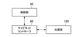
- FIG. 2 is a block diagram illustrating a functional configuration example of the automatic transaction apparatus 1.
- the automatic transaction apparatus 1 includes a control unit 50, a cabinet controller 60, and a light source unit 120.
- the control unit 50 has a function of controlling the entire operation of the automatic transaction apparatus 1.
- the control unit 50 may control the cabinet controller 60, and the cabinet controller 60 may control the light source unit 120 (blinking or lighting of the light source unit 120) according to the control of the control unit 50.
- the control part 50 is irradiated with light from the light source part 120 provided in the banknote insertion part 10 at the time of payment and withdrawal.
- the light source unit 120 may be controlled.
- the control part 50 is irradiated with light from the light source part 120 provided in the coin insertion part 20 at the time of payment and withdrawal.
- the light source unit 120 may be controlled as described above.
- the control unit 50 receives light from the light source unit 120 provided in the card insertion unit 30 at the start and end of the transaction. You may control the light source part 120 so that it may be irradiated.
- the medium insertion part for example, the banknote insertion part 10, the coin insertion part 20, the card insertion part 30 etc.
- the number of light source units 120 generally increases accordingly. As the number of the light source units 120 increases, there is a possibility that a failure may occur in any of the light source units 120 and the maintenance may be complicated. Further, the power consumption by the light source unit 120 may increase as the number of the light source units 120 increases. Therefore, in the present specification, it is possible to prompt the customer's attention to the medium insertion unit (for example, the bill insertion unit 10, the coin insertion unit 20, the card insertion unit 30) while suppressing an increase in the number of the light source units 120.
- the medium insertion unit for example, the bill insertion unit 10, the coin insertion unit 20, the card insertion unit 30
- the banknote insertion unit 10 will be mainly described as an example of the medium insertion unit. ) Can also be effectively applied. Furthermore, in this specification, an example in which the customer's attention is urged to the medium insertion unit will be mainly described. It can also be applied effectively. Therefore, the light-emitting device which has the structure similar to the banknote insertion part 10 demonstrated below can also be provided.
- the bill insertion unit 10A-1 includes a light guide plate 110.
- the material of the light guide plate 110 is not particularly limited, but may be a transparent resin, for example.
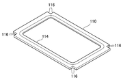
- FIG. 3 is a perspective view of the light guide plate 110 according to the first embodiment as viewed from the customer side.
- the light guide plate 110 includes a diffusion unit 114 that diffuses light, and the light diffused by the diffusion unit 114 is configured to reach a customer.
- the diffusion part 114 may be formed by embossing the light guide plate 110.
- notches 116 are provided at the four corners of the light guide plate 110. Details of the diffusion part 114 and the notch part 116 will be described later.
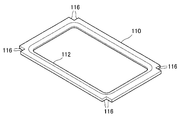
- FIG. 4 is a perspective view of the light guide plate 110 according to the first embodiment viewed from the side opposite to the customer side.
- the light guide plate 110 includes a reflection plate 112 that reflects the light irradiated inside the light guide plate 110, and the light reflected by the reflection plate 112 reaches the diffusion unit 114. Has been. The light reaching the diffusion unit 114 is diffused by the diffusion unit 114 and reaches the customer.
- the banknote insertion portion 10A-1 including such a light guide plate 110 will be described in more detail.
- FIG. 5 is a plan view of the banknote insertion portion 10A-1 according to the first embodiment as viewed from the customer side.
- FIG. 6 is a cross-sectional view taken along a cross section A1-A1 of the bill insertion portion 10A-1 shown in FIG.
- the bill insertion part 10A-1 includes a light guide plate 110 provided so as to surround the bill insertion slot P.
- the shape of the bill insertion slot P is rectangular, but the shape of the bill insertion slot P is not particularly limited. Therefore, the shape of the light guide plate 110 may be appropriately changed according to the shape of the bill insertion slot P.
- the bill insertion portion 10A-1 may be provided with a shutter, and the shutter may appropriately open and close the bill insertion slot P.
- the bill insertion unit 10A-1 includes a plurality of light source units 120.
- two light source units 120 are provided corresponding to each side of the bill insertion slot P. More specifically, there are provided two light source sections 120 that irradiate light that is parallel to one side of the bill insertion slot P and opposite to each other.
- the number of light source units 120 is not particularly limited. Referring to FIG. 5, coordinate axes x, y, z, and w are shown along each side of the bill insertion slot P.
- the light guide plate 110 includes a reflection plate 112.
- the reflector 112 reflects the light emitted from the light source unit 120.
- the diffusion unit 114 diffuses the light reflected by the reflection plate 112 to the outside of the light guide plate 110.
- FIG. 6 shows a range L through which the light diffused by the diffusion unit 114 passes. According to this configuration, since the light emitted from the light source unit 120 is reflected and reaches the customer's eyes, the light emitted from the light source unit 120 directly reaches the customer's eyes. The customer's attention to the bill insertion slot P can be urged while suppressing an increase in the number of the light source sections 120.
- the diffusing unit 114 is preferably provided so as to be parallel to the irradiation direction of light from the light source unit 120. According to such a configuration, it becomes possible to diffuse more light, and thus it is possible to more efficiently suppress an increase in the number of light source units 120.
- the reflector 112 is preferably provided so as to be parallel to the irradiation direction of the light from the light source unit 120. According to such a configuration, more light can be reflected, and thus an increase in the number of light source units 120 can be more efficiently suppressed.
- the light guide plate 110 may have a notch 116.
- notches 116 are formed at the four corners of the light guide plate 110.
- the notch 116 is not formed, the light emitted from the light source 120 is easily collected at the four corners of the light guide plate 110. For this reason, a phenomenon may occur in which light diffused by the diffusion portions 114 near the four corners of the light guide plate 110 becomes stronger. As shown in FIG. 5, such a phenomenon can be reduced if the light source unit 120 is disposed in the notch 116.
- the bill insertion part 10A-1 may include a light shielding member that covers at least a part of the light guide plate 110.
- the diffusing portion 114 may not be covered with the light shielding member. This is because if the light diffused by the diffusion unit 114 is blocked, the light may not reach the customer. Further, the connection portion between the light source unit 120 and the light guide plate 110 may not be covered with the light shielding member. This is because it is difficult to cover the connection portion between the light source unit 120 and the light guide plate 110 with a light shielding member. Other regions of the light guide plate 110 may be covered with a light shielding member.
- the color of the light shielding member is not particularly limited, and may be white or another color. Further, the light shielding member may be a sheet or a paint.
- the light emitted from the light source unit 120 becomes weaker as the distance from the light source unit 120 increases, and the light diffused by the diffusion unit 114 may become non-uniform. Therefore, it is preferable that the light diffused by the diffusion unit 114 is uniform.
- the reflector 112 may reflect the light emitted by the light source unit 120 so that the reflectance changes according to the distance from the light source unit 120. More specifically, the reflector 112 may reflect light such that the reflectance increases as the distance from the light source unit 120 increases.
- the reflectance may be changed by changing the concentration of the coating applied to the reflecting plate 112.
- the concentration of the coating applied to the reflecting plate 112 may be changed according to the distance from the light source unit 120. More specifically, the concentration of the coating applied to the reflecting plate 112 may be increased as the distance from the light source unit 120 increases.
- the color of the coating is not particularly limited, and may be white or another color.
- the diffusion unit 114 may diffuse the light reflected by the reflector 112 so that the diffusivity changes according to the distance from the light source unit 120. More specifically, the diffusing unit 114 may diffuse light so that the diffusivity increases as the distance from the light source unit 120 increases. How to change the diffusion rate is not particularly limited.
- the diffusivity may be changed by changing the transparency of the diffusing unit 114 (the fogging degree of the diffusing unit 114).
- the transparency of the diffusing unit 114 (the degree of cloudiness of the diffusing unit 114) may be changed according to the distance from the light source unit 120. More specifically, the transparency of the diffusing unit 114 may be increased as the distance from the light source unit 120 increases (the cloudiness degree of the diffusing unit 114 decreases as the distance from the light source unit 120 increases). To do so).
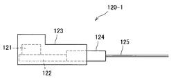
- FIG. 7 is a side view of the light source unit 120 according to the first embodiment.
- FIG. 8 is a plan view of the light source unit 120 according to the first embodiment viewed in the direction opposite to the irradiation direction.
- FIGS. 7 and 8 show a configuration example of the light source unit 120-1 as an example of the light source unit 120.
- the light source unit 120-1 includes a light source 121, a substrate 122, a light source storage unit 123, a power connector 124, and a power cord 125.
- the type of the light source 121 is not particularly limited.
- the light source 121 may be an LED (light emitting diode).
- the light source 121 may be provided on the substrate 122.
- a power connector 124 is connected to the substrate 122, and a current sent from a power source (not shown) is supplied to the light source 121 via the power cord 125, the power connector 124 and the substrate 122. Then, the light source 121 can emit light using the supplied current.
- the light source 121 and the substrate 122 may be stored in the light source storage unit 123. If the light source storage unit 123 is a transparent material, the light emitted from the light source 121 may be sent to the inside of the light guide plate 110 through the light source storage unit 123. Further, in order to reduce leakage of light emitted from the light source 121, the distal end portion of the light source storage unit 123 may be able to be inserted into the light guide plate 110. As shown in FIGS. 7 and 8, a power connector 124 may be inserted into the light source housing 123.
- the light emitted from the light source 121 has weak directivity.
- the directivity of light emitted from the light source 121 is weaker, the amount of light that leaks to the outside of the light guide plate 110 before reaching the diffusion unit 114 increases, and the light diffused by the diffusion unit 114 May become non-uniform. Therefore, some measures for enhancing the directivity of the light emitted from the light source 121 may be taken. Below, the example of the concrete method for strengthening the directivity of the light irradiated from the light source 121 is demonstrated.
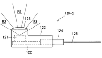
- FIG. 9 is a side view of the light source unit 120-2 having the focusing lens 126.
- FIG. 10 is a plan view of the light source unit 120-2 including the focusing lens 126 as seen in the direction opposite to the irradiation direction.
- the light source 121 may irradiate light inside the light guide plate 110 via the focusing lens 126. In this way, since the light emitted from the light source 121 is focused by the focusing lens 126, the directivity of the light emitted from the light source 121 can be increased.
- the focusing lens 126 may be arranged in any manner, but may be attached to the distal end portion of the light source storage unit 123, for example, as shown in FIG. Referring to FIG. 9, a range R1 through which the light focused by the focusing lens 126 passes is shown.
- a gap may be formed between the focusing lens 126 and the light source storage unit 123, there may be light leaking from the gap. Further, the light passing through the end of the focusing lens 126 may leak without being focused.
- FIG. 9 shows ranges R2 and R3 through which light leaks in this way.
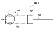
- FIG. 11 is a side view of the light source unit 120-3 including the light shielding tube 127.
- FIG. 12 is a plan view of the light source unit 120-3 including the light-shielding tube 127 as seen in the direction opposite to the irradiation direction.
- the light shielding tube 127 may be attached to the light source housing 123 so as to shield light leaking from a gap generated between the focusing lens 126 and the light source housing 123. .
- the light shielding tube 127 may be attached to the light source housing 123 so as to shield light leaking from the end of the focusing lens 126.
- a light shielding member may be used instead of the light shielding tube 127.
- the color of the light shielding member is not particularly limited, and may be white or another color. Further, the light shielding member may be a sheet or a paint.
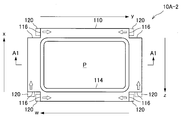
- FIG. 13 is a plan view of the bill insertion part 10A-2 when the number of the light source parts 120 is six as viewed from the customer side.
- FIG. 13 it is assumed that light irradiated from the light source unit 120 on the shorter side than the long side of the bill insertion slot P can easily reach the end of the light guide plate 110. Accordingly, as in the example shown in FIG. 13, one light source unit 120 is provided corresponding to each of the two short sides of the bill insertion slot P, and each of the two long sides of the bill insertion slot P is corresponded. Two light source units 120 may be provided.
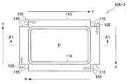
- FIG. 14 is a plan view of the bill insertion portion 10A-3 according to the case where the number of the light source portions 120 is four as viewed from the customer side. As in the example illustrated in FIG. 14, one light source unit 120 may be provided corresponding to each side of the bill insertion slot P.
- the first embodiment has been described above.
- the second embodiment will be described.
- the example using the focusing lens 126 has been described as an example of a specific method for enhancing the directivity of light emitted from the light source 121.
- an example of irradiating light inside an optical fiber will be described as an example of a specific method for enhancing the directivity of light emitted from the light source 121.
- the description of the same configuration as that of the first embodiment is omitted.
- FIG. 15 is a plan view of the banknote insertion part 10B-1 according to the second embodiment as viewed from the customer side.
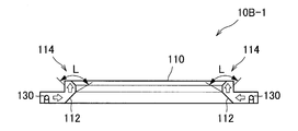
- FIG. 16 is a cross-sectional view taken along a cross section A2-A2 of the bill insertion portion 10B-1 shown in FIG.
- the bill insertion part 10 ⁇ / b> B- 1 includes an optical fiber 130 provided inside the light guide plate 110.
- the light source unit 120 irradiates light inside the optical fiber 130, and the reflection plate 112 reflects light leaked from the side surface of the optical fiber 130.
- the diffusion unit 114 diffuses the light reflected by the reflection plate 112 to the outside of the light guide plate 110.
- FIG. 16 shows a range L through which the light diffused by the diffusion unit 114 passes.
- the light emitted from the light source unit 120 is reflected and reaches the customer's eyes, the light emitted from the light source unit 120 is directly Compared with the case where the eye reaches the eyes, it is possible to prompt the customer to pay attention to the bill insertion slot P while suppressing an increase in the number of the light source units 120.
- the diffusion unit 114 is preferably provided so as to be parallel to the axial direction of the optical fiber 130. According to such a configuration, it becomes possible to diffuse more light, and thus it is possible to more efficiently suppress an increase in the number of light source units 120.
- the reflecting plate 112 is preferably provided so as to be parallel to the axial direction of the optical fiber 130. According to such a configuration, it becomes possible to diffuse more light, and thus it is possible to more efficiently suppress an increase in the number of light source units 120.
- the number of light source units 120 is not particularly limited.
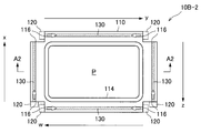
- FIG. 17 is a plan view of the banknote insertion part 10B-2 when the number of the light source parts 120 is six as viewed from the customer side.
- the number of the light source parts 120 is six as viewed from the customer side.
- Two light source units 120 may be provided.
- FIG. 18 is a plan view of the banknote insertion part 10B-3 when the number of the light source parts 120 is four as viewed from the customer side. As in the example shown in FIG. 18, one light source unit 120 may be provided corresponding to each side of the bill insertion slot P.
- control unit 50 for controlling the overall operation of the automatic transaction apparatus 1 may be configured by dedicated hardware, or the CPU built in the automatic transaction apparatus 1 stores the program stored in the ROM in the RAM. It may be realized by expanding and executing. In addition to providing such a program, a storage medium storing such a program may also be provided.
- the example in which the light guide plate 110 is provided so as to surround the banknote insertion slot P has been described in consideration of further encouraging human attention to the banknote insertion slot P as an example of the predetermined area.
- the light guide plate 110 may be divided and provided.
- the light guide plate 110 may be divided at any of the four corners, or may be divided at all of the four corners.
- the light guide plate 110 may be divided at any side, or may be divided at two long sides or two short sides.
Landscapes
- Physics & Mathematics (AREA)
- General Physics & Mathematics (AREA)
- Optics & Photonics (AREA)
- Planar Illumination Modules (AREA)
Abstract
光源の数の増加を抑えながら対象物に対する人の注目を促すことが可能となることを目的とした自動取引装置であって、紙幣挿入口(P)を囲むように設けられた導光板(110)と、導光板(110)の内部に光を照射する光源部(120)と、を備え、導光板(110)は、光源部(120)により照射された光を反射する反射板と、反射板により反射された光を導光板(110)の外部に拡散する拡散部(114)と、を備える、自動取引装置である。
Description
本発明は、発光装置および自動取引装置に関するものである。
従来、所定の領域に対する人の注目を促すために領域の周囲に設けられた光源から光を照射する技術が開示されている(例えば、特許文献1参照)。領域としては、自動取引装置に設けられた媒体挿入口、店舗の前に設置された看板などが挙げられる。かかる技術が用いられた場合、光源から照射された光が直接的に人の目に到達すると、その人は光源がある方向に視線を向け、光源に囲まれた領域に注目するようになる。
しかしながら、より広い範囲に対して人の注目を促そうとすれば、それだけ光源の数が増加してしまうのが一般的である。そこで、本発明は、上記問題に鑑みてなされたものであり、本発明の目的とするところは、光源の数の増加を抑えながら所定の領域に対する人の注目を促すことが可能な技術を提供することにある。
上記問題を解決するために、本発明のある観点によれば、所定の領域の周辺に設けられた導光板と、前記導光板の内部に光を照射する光源部と、を備え、前記導光板は、前記光源部により照射された光を反射する反射板と、前記反射板により反射された光を前記導光板の外部に拡散する拡散部と、を備える、発光装置が提供される。
前記光源部は、集束レンズを備え、前記集束レンズを介して前記導光板の内部に光を照射してよい。
前記発光装置は、前記導光板の内部に設けられた光ファイバを備え、前記光源部は、前記光ファイバの内部に光を照射し、前記反射板は、前記光ファイバの側面から漏洩された光を反射してよい。
前記発光装置は、前記導光板の少なくとも一部を覆う遮光部材を備えてよい。
前記反射板は、前記光源部からの距離に応じて反射率が変化するように前記光源部により照射された光を反射してよい。
前記拡散部は、前記光源部からの距離に応じて拡散率が変化するように前記反射板により反射された光を拡散してよい。
前記光源部は、前記導光板に形成された切り欠き部に配置されてよい。
前記導光板は、前記所定の領域を囲むように設けられてよい。
また、本発明の別の観点によれば、所定の媒体が挿入される挿入口の周辺に設けられた導光板と、前記導光板の内部に光を照射する光源部と、を備え、前記導光板は、前記光源部により照射された光を反射する反射板と、前記反射板により反射された光を前記導光板の外部に拡散する拡散部と、を備える、自動取引装置が提供される。
前記光源部は、集束レンズを備え、前記集束レンズを介して前記導光板の内部に光を照射してよい。
前記自動取引装置は、前記導光板の内部に設けられた光ファイバを備え、前記光源部は、前記光ファイバの内部に光を照射し、前記反射板は、前記光ファイバの側面から漏洩された光を反射してよい。
前記自動取引装置は、前記導光板の少なくとも一部を覆う遮光部材を備えてよい。
前記反射板は、前記光源部からの距離に応じて反射率が変化するように前記光源部により照射された光を反射してよい。
前記拡散部は、前記光源部からの距離に応じて透過率が変化するように前記反射板により反射された光を拡散してよい。
前記光源部は、前記導光板に形成された切り欠き部に配置されてよい。
前記導光板は、前記所定の媒体が挿入される挿入口を囲むように設けられてよい。
以上説明したように本発明によれば、光源の数の増加を抑えながら所定の領域に対する人の注目を促すことが可能となる。
以下に添付図面を参照しながら、本発明の好適な実施の形態について詳細に説明する。なお、本明細書および図面において、実質的に同一の機能構成を有する構成要素については、同一の符号を付することにより重複説明を省略する。
また、本明細書および図面において、実質的に同一の機能構成を有する複数の構成要素を、同一の符号の後に異なるアルファベットまたは数字を付して区別する場合もある。ただし、実質的に同一の機能構成を有する複数の構成要素の各々を特に区別する必要がない場合、同一符号のみを付する。
まず、本発明の実施形態に係る自動取引装置1の全体構成の例について説明する。図1は、本発明の実施形態に係る自動取引装置1の外観を示す図である。図1を参照すると、本発明の実施形態に係る自動取引装置1は、紙幣挿入部10と、硬貨挿入部20と、カード挿入部30と、表示部40とを備えている。なお、本明細書においては、自動取引装置1がATM(automated teller machine)である場合を主に説明するが、自動取引装置1はATM以外の装置であってもよい。
表示部40は、顧客に対して取引に関する情報を表示する表示機能、顧客による操作を受け入れる入力機能などを有する。ここで、表示機能は、LCD(Liquid Crystal Display)などのディスプレイにより実現されてよい。また、入力機能は、タッチパネルなどの入力装置により実現されてよい。例えば、表示部40は、取引(例えば、入金、出金など)を選択するための画面を表示し、取引を特定するための操作を顧客から受け入れてよい。
取引が開始されるに際しては、顧客によってカード挿入部30からカードが挿入される。カード挿入部30から挿入されたカードからは、自動取引装置1によって情報が読み取られ、カードから読み取られた情報は、自動取引装置1によってなされる取引に用いられ得る。自動取引装置1による取引が終了すると、カード挿入部30から顧客にカードが排出される。
例えば、入金時には、顧客から紙幣挿入部10に挿入された紙幣が自動取引装置1に収納されてよい。また、入金時には、顧客から硬貨挿入部20に挿入された硬貨が自動取引装置1に収納されてよい。一方、出金時には、自動取引装置1に収納されている紙幣が紙幣挿入部10から顧客に排出されてよい。また、出金時には、自動取引装置1に収納されている硬貨が硬貨挿入部20から顧客に排出されてよい。
図2は、自動取引装置1の機能構成例を示すブロック図である。図2を参照すると、自動取引装置1は、制御部50と、キャビネットコントローラ60と、光源部120とを備えている。制御部50は、自動取引装置1の動作全体を制御する機能を有する。例えば、制御部50は、キャビネットコントローラ60を制御し、キャビネットコントローラ60は、制御部50の制御に従って、光源部120(光源部120の点滅または点灯)を制御してよい。
例えば、紙幣挿入部10に光源部120が設けられている場合には、制御部50は、入金時および出金時に、紙幣挿入部10に設けられている光源部120から光が照射されるように光源部120を制御してよい。また、例えば、硬貨挿入部20に光源部120が設けられている場合には、制御部50は、入金時および出金時に、硬貨挿入部20に設けられている光源部120から光が照射されるように光源部120を制御してよい。
同様に、例えば、カード挿入部30に光源部120が設けられている場合には、制御部50は、取引開始時および取引終了時に、カード挿入部30に設けられている光源部120から光が照射されるように光源部120を制御してよい。このように顧客に注目させたい媒体挿入部(例えば、紙幣挿入部10、硬貨挿入部20、カード挿入部30など)から光が照射されるようにすれば、取引をより円滑に行うことが可能になることが期待される。
しかし、より広範囲に対して顧客の注目を促そうとすれば、それだけ光源部120の数が増加してしまうのが一般的である。光源部120の数が増加するほど、光源部120の何れかに故障が発生する可能性が高まり保守の煩雑化を伴う可能性がある。また、光源部120の数が増加するほど、光源部120による消費電力が増加する可能性もある。そこで、本明細書においては、光源部120の数の増加を抑えながら媒体挿入部(例えば、紙幣挿入部10、硬貨挿入部20、カード挿入部30など)に対する顧客の注目を促すことが可能な技術を主に提案する。
なお、本明細書においては、媒体挿入部の例として紙幣挿入部10を主に説明するが、本発明の実施形態は、他の媒体挿入部(例えば、硬貨挿入部20、カード挿入部30など)にも有効に適用され得る。さらに、本明細書においては、媒体挿入部に対して顧客の注目を促す例を主に説明するが、本発明の実施形態は、媒体挿入部以外のあらゆる領域に対して人の注目を促す場合にも有効に適用され得る。したがって、以下に説明する紙幣挿入部10と同様な構成を有する発光装置も提供され得る。
以上、本発明の実施形態に係る自動取引装置1の全体構成の例について説明した。
<第1の実施形態>
続いて、第1の実施形態について説明する。以下に説明するように、第1の実施形態に係る紙幣挿入部10A-1は、導光板110を備える。導光板110の材質は特に限定されないが、例えば、透明樹脂であってよい。図3は、第1の実施形態に係る導光板110を顧客側から見た斜視図である。図3を参照すると、導光板110は、光を拡散する拡散部114を備えており、拡散部114によって拡散された光が顧客に到達するように構成されている。例えば、導光板110に対するシボ加工により拡散部114が形成されてよい。また、導光板110の四隅には、切り欠き部116が設けられている。拡散部114および切り欠き部116についての詳細は後に説明する。
続いて、第1の実施形態について説明する。以下に説明するように、第1の実施形態に係る紙幣挿入部10A-1は、導光板110を備える。導光板110の材質は特に限定されないが、例えば、透明樹脂であってよい。図3は、第1の実施形態に係る導光板110を顧客側から見た斜視図である。図3を参照すると、導光板110は、光を拡散する拡散部114を備えており、拡散部114によって拡散された光が顧客に到達するように構成されている。例えば、導光板110に対するシボ加工により拡散部114が形成されてよい。また、導光板110の四隅には、切り欠き部116が設けられている。拡散部114および切り欠き部116についての詳細は後に説明する。
図4は、第1の実施形態に係る導光板110を顧客側とは反対側から見た斜視図である。図4を参照すると、導光板110は、導光板110の内部に照射された光を反射する反射板112を備えており、反射板112によって反射された光が拡散部114に到達するように構成されている。拡散部114に到達した光は、拡散部114によって拡散されて顧客に到達する。このような導光板110を備える紙幣挿入部10A-1についてさらに詳細に説明する。
図5は、第1の実施形態に係る紙幣挿入部10A-1を顧客側から見た平面図である。また、図6は、図5に示した紙幣挿入部10A-1の断面A1-A1における断面図である。図5を参照すると、紙幣挿入部10A-1は、紙幣挿入口Pを囲むように設けられた導光板110を備えている。図5に示した例では、紙幣挿入口Pの形状は矩形となっているが、紙幣挿入口Pの形状は特に限定されない。したがって、導光板110の形状も紙幣挿入口Pの形状に応じて適宜に変更されてよい。なお、紙幣挿入部10A-1にはシャッタが設けられてよく、当該シャッタが適宜に紙幣挿入口Pを開閉してよい。
また、図5を参照すると、紙幣挿入部10A-1は、複数の光源部120を備えている。図5に示した例では、紙幣挿入口Pの各辺に対応して2つの光源部120が設けられている。より詳細には、紙幣挿入口Pの1つの辺に対して平行、かつ、互いに反対方向となるような光を照射する2つの光源部120が設けられている。しかし、後に説明するように、光源部120の数は特に限定されない。図5を参照すると、紙幣挿入口Pの各辺に沿って座標軸x、y、z、wが示されている。
また、図6を参照すると、導光板110は反射板112を備えている。反射板112は、光源部120から照射された光を反射する。また、拡散部114は、反射板112によって反射された光を導光板110の外部に拡散する。図6には、拡散部114によって拡散された光の通過する範囲Lが示されている。かかる構成によれば、光源部120から照射された光が反射されてから顧客の目に到達するため、光源部120から照射された光が直接的に顧客の目に到達する場合と比較して、光源部120の数の増加を抑えながら紙幣挿入口Pに対する顧客の注目を促すことが可能となる。
なお、図5に示された例のように、拡散部114は、光源部120からの光の照射方向に対して平行となるように設けられるのがよい。かかる構成によれば、より多くの光を拡散させることが可能となるため、光源部120の数の増加をより効率よく抑えることが可能となる。また、反射板112は、光源部120からの光の照射方向に対して平行となるように設けられるのがよい。かかる構成によれば、より多くの光を反射させることが可能となるため、光源部120の数の増加をより効率よく抑えることが可能となる。
また、導光板110には、切り欠き部116が形成されていてもよい。図5を参照すると、導光板110の四隅それぞれには、切り欠き部116が形成されている。切り欠き部116が形成されていない場合には、導光板110の四隅において光源部120から照射された光が集まり易くなる。そのため、導光板110の四隅付近の拡散部114によって拡散される光がより強くなってしまうという現象が起こり得る。図5に示すように、切り欠き部116に光源部120が配置されれば、かかる現象が低減され得る。
導光板110から光が漏れ出してしまった場合には、光源部120から照射された光を効率よく拡散部114に送ることができなくなってしまう可能性がある。また、導光板110から光が漏れ出してしまった場合には、光源部120から照射された光を均一に拡散部114に送ることができなくなってしまう可能性がある。したがって、紙幣挿入部10A-1は、導光板110の少なくとも一部を覆う遮光部材を備えてもよい。
より詳細には、拡散部114は遮光部材によって覆われなくてよい。拡散部114によって拡散された光が遮光されてしまうと顧客まで光が到達しなくなってしまう可能性があるからである。また、光源部120と導光板110との接続部分も遮光部材によって覆われなくてよい。光源部120と導光板110との接続部分には遮光部材で覆うことが困難だからである。導光板110のうち他の領域は、遮光部材で覆われてもよい。なお、遮光部材の色は特に限定されず、白色であってもよいし、他の色であってもよい。また、遮光部材は、シートであってもよいし、塗装であってもよい。
また、光源部120から照射された光は、光源部120からの距離が遠くなるほど弱まってしまい、拡散部114によって拡散される光が不均一になってしまう可能性がある。そこで、拡散部114によって拡散される光が均一になるようにするとよい。例えば、反射板112は、光源部120からの距離に応じて反射率が変化するように光源部120により照射された光を反射してよい。より詳細には、反射板112は、光源部120からの距離が遠くなるほど、反射率が高くなるように光を反射してよい。
反射率をどのように変化させるかは特に限定されない。例えば、光を反射する性質を有する塗装を反射板112に施すことを想定した場合、反射板112に施される塗装の濃度を変化させることによって反射率を変化させてもよい。具体的には、反射板112に施される塗装の濃度を、光源部120からの距離に応じて変化させればよい。より詳細には、反射板112に施される塗装の濃度が、光源部120からの距離が遠くなるほど、高くなるようにすればよい。塗装の色は特に限定されず、白色であってもよいし、他の色であってもよい。
また、例えば、拡散部114は、光源部120からの距離に応じて拡散率が変化するように反射板112により反射された光を拡散してよい。より詳細には、拡散部114は、光源部120からの距離が遠くなるほど、拡散率が高くなるように光を拡散してよい。拡散率をどのように変化させるかは特に限定されない。
例えば、拡散部114の透明度(拡散部114の曇り度合い)を変化させることによって拡散率を変化させてもよい。具体的には、拡散部114の透明度(拡散部114の曇り度合い)を、光源部120からの距離に応じて変化させればよい。より詳細には、拡散部114の透明度が、光源部120からの距離が遠くなるほど、高くなるようにすればよい(拡散部114の曇り度合いが、光源部120からの距離が遠くなるほど、低くなるようにすればよい)。
続いて、光源部120の構成例について説明する。図7は、第1の実施形態に係る光源部120の側面図である。また、図8は、第1の実施形態に係る光源部120を照射方向とは逆方向に見た平面図である。特に、図7および図8には、光源部120の一例として光源部120-1の構成例が示されている。図7および図8に示されたように、光源部120‐1は、光源121と、基板122と、光源収納部123と、電源コネクタ124と、電源コード125とを備えている。
光源121の種類は特に限定されないが、例えば、光源121は、LED(light emitting diode)であってよい。図7に示すように、光源121は基板122の上に設けられてよい。また、図7に示すように、基板122には電源コネクタ124が接続されており、図示しない電源から送られた電流が、電源コード125、電源コネクタ124および基板122を介して光源121に供給されると、光源121は、供給された電流を用いて発光することが可能である。
また、図7および図8に示すように、光源収納部123には、光源121および基板122が収納されてよい。光源収納部123が透明な材質であれば、光源121から照射された光は、光源収納部123を通過して導光板110の内部に送られ得る。また、光源121から照射された光の漏れを少なくするため、光源収納部123の先端部分は、導光板110に差し込むことが可能であってよい。また、図7および図8に示すように、光源収納部123には、電源コネクタ124が差し込まれてよい。
ここで、光源121から照射される光は、指向性が弱い場合も想定される。例えば、光源121から照射される光の指向性が弱いほど、拡散部114に到達しないうちに導光板110の外部に漏れてしまう光の量も多くなってしまい、拡散部114によって拡散される光が不均一になってしまう可能性がある。そこで、光源121から照射される光の指向性を強めるための何らかの措置が施されてもよい。以下においては、光源121から照射される光の指向性を強めるための具体的な手法の例を説明する。
まず、光源121から照射される光の指向性を強めるための具体的な手法の例として、集束レンズを用いる場合を説明する。図9は、集束レンズ126を備えた光源部120‐2の側面図である。また、図10は、集束レンズ126を備えた光源部120‐2を照射方向とは逆方向に見た平面図である。図9および図10に示すように、光源121は、集束レンズ126を介して導光板110の内部に光を照射するようにしてもよい。このようにすれば、光源121から照射された光が集束レンズ126において集束されるため、光源121から照射される光の指向性を強めることが可能となる。
なお、集束レンズ126はどのように配置されてもよいが、例えば、図9に示すように、光源収納部123の先端部分に取り付けられてもよい。図9を参照すると、集束レンズ126によって集束された光の通過する範囲R1が示されている。ここで、集束レンズ126と光源収納部123との間には隙間が生じ得るため、隙間から漏れ出してしまう光も存在し得る。さらに、集束レンズ126の端部を通過する光は、集束されずに漏れ出してしまう可能性もある。図9には、このようにして漏れ出してしまう光の通過する範囲R2、R3が示されている。
このようにして漏れ出してしまう光は、導光板110の一部を集中的に照らしてしまう可能性があるため、導光板110の輝度を不均一にしてしまう可能性がある。したがって、このようにして漏れ出してしまう光を遮光チューブによって遮るようにしてもよい。図11は、遮光チューブ127を備えた光源部120-3の側面図である。また、図12は、遮光チューブ127を備えた光源部120-3を照射方向とは逆方向に見た平面図である。
例えば、図11および図12に示すように、遮光チューブ127は、集束レンズ126と光源収納部123との間に生じる隙間から漏れ出す光を遮光するように光源収納部123に装着されてもよい。また、例えば、図11および図12に示すように、遮光チューブ127は、集束レンズ126の端部から漏れ出す光を遮光するように光源収納部123に装着されてもよい。なお、遮光チューブ127の代わりに、遮光部材が用いられてもよい。遮光部材の色は特に限定されず、白色であってもよいし、他の色であってもよい。また、遮光部材は、シートであってもよいし、塗装であってもよい。
以上、光源部120の構成例について説明した。上記においては、紙幣挿入口Pの各辺に対応して2つの光源部120が設けられている例を説明した。しかし、光源部120の数は特に限定されない。図13は、光源部120の数を6つとした場合に係る紙幣挿入部10A-2を顧客側から見た平面図である。例えば、紙幣挿入口Pの長辺より短辺のほうが光源部120から照射された光が導光板110の端まで到達しやすいことが想定される。したがって、図13に示した例のように、紙幣挿入口Pの2つの短辺それぞれに対応して1つずつの光源部120が設けられ、紙幣挿入口Pの2つの長辺それぞれに対応して2つずつの光源部120が設けられてもよい。
図14は、光源部120の数を4つとした場合に係る紙幣挿入部10A-3を顧客側から見た平面図である。図14に示した例のように、紙幣挿入口Pの各辺それぞれに対応して1つずつの光源部120が設けられてもよい。
以上、第1の実施形態について説明した。
<第2の実施形態>
続いて、第2の実施形態について説明する。第1の実施形態においては、光源121から照射される光の指向性を強めるための具体的な手法の例として、集束レンズ126を用いる例を説明した。第2の実施形態においては、光源121から照射される光の指向性を強めるための具体的な手法の例として、光ファイバの内部に光を照射する例を説明する。なお、第2の実施形態において第1の実施形態と同様の構成については説明を省略する。
続いて、第2の実施形態について説明する。第1の実施形態においては、光源121から照射される光の指向性を強めるための具体的な手法の例として、集束レンズ126を用いる例を説明した。第2の実施形態においては、光源121から照射される光の指向性を強めるための具体的な手法の例として、光ファイバの内部に光を照射する例を説明する。なお、第2の実施形態において第1の実施形態と同様の構成については説明を省略する。
図15は、第2の実施形態に係る紙幣挿入部10B-1を顧客側から見た平面図である。図16は、図15に示した紙幣挿入部10B-1の断面A2-A2における断面図である。図15を参照すると、紙幣挿入部10B-1は、導光板110の内部に設けられた光ファイバ130を備えている。光源部120は、光ファイバ130の内部に光を照射し、反射板112は、光ファイバ130の側面から漏洩された光を反射する。また、拡散部114は、反射板112によって反射された光を導光板110の外部に拡散する。
図16には、拡散部114によって拡散された光の通過する範囲Lが示されている。かかる構成によれば、第1の実施形態と同様に、光源部120から照射された光が反射されてから顧客の目に到達するため、光源部120から照射された光が直接的に顧客の目に到達する場合と比較して、光源部120の数の増加を抑えながら紙幣挿入口Pに対する顧客の注目を促すことが可能となる。
なお、図15に示された例のように、拡散部114は、光ファイバ130の軸方向に対して平行となるように設けられるのがよい。かかる構成によれば、より多くの光を拡散させることが可能となるため、光源部120の数の増加をより効率よく抑えることが可能となる。また、反射板112は、光ファイバ130の軸方向に対して平行となるように設けられるのがよい。かかる構成によれば、より多くの光を拡散させることが可能となるため、光源部120の数の増加をより効率よく抑えることが可能となる。
また、第2の実施形態においても光源部120の数は特に限定されない。図17は、光源部120の数を6つとした場合に係る紙幣挿入部10B-2を顧客側から見た平面図である。例えば、紙幣挿入口Pの長辺より短辺のほうが光源部120から照射された光が導光板110の端まで到達しやすいことが想定される。したがって、図17に示した例のように、紙幣挿入口Pの2つの短辺それぞれに対応して1つずつの光源部120が設けられ、紙幣挿入口Pの2つの長辺それぞれに対応して2つずつの光源部120が設けられてもよい。
図18は、光源部120の数を4つとした場合に係る紙幣挿入部10B-3を顧客側から見た平面図である。図18に示した例のように、紙幣挿入口Pの各辺それぞれに対応して1つずつの光源部120が設けられてもよい。
以上、第2の実施形態について説明した。
以上、添付図面を参照しながら本発明の好適な実施形態について詳細に説明したが、本発明はかかる例に限定されない。本発明の属する技術の分野における通常の知識を有する者であれば、請求の範囲に記載された技術的思想の範疇内において、各種の変更例または修正例に想到し得ることは明らかであり、これらについても、当然に本発明の技術的範囲に属するものと了解される。
例えば、自動取引装置1の動作全体を制御するための制御部50は、専用のハードウェアによって構成されてもよいし、自動取引装置1に内蔵されたCPUがROMに記憶されたプログラムをRAMに展開して実行することにより実現されてもよい。かかるプログラムが提供され得る他、かかるプログラムを記憶させた記憶媒体も提供され得る。
また、上記においては、所定の領域の一例としての紙幣挿入口Pに対する人の注目をより強く促すことを考慮して、導光板110が紙幣挿入口Pを囲むように設けられる例を説明した。しかし、導光板110は紙幣挿入口Pの周辺に設けられていれば、紙幣挿入口Pに対する人の注目を促すことが可能である。したがって、導光板110は分断されて設けられていてもよい。例えば、導光板110は、四隅の何れかにおいて分断されていてもよく、四隅のすべてにおいて分断されていてもよい。また、例えば、導光板110は、何れかの辺において分断されていてもよく、2つの長辺または2つの短辺において分断されていてもよい。
1 自動取引装置
10 紙幣挿入部
20 硬貨挿入部
30 カード挿入部
40 表示部
50 制御部
60 キャビネットコントローラ
110 導光板
112 反射板
114 拡散部
116 切り欠き部
120 光源部
121 光源
122 基板
123 光源収納部
124 電源コネクタ
125 電源コード
126 集束レンズ
127 遮光チューブ
130 光ファイバ
10 紙幣挿入部
20 硬貨挿入部
30 カード挿入部
40 表示部
50 制御部
60 キャビネットコントローラ
110 導光板
112 反射板
114 拡散部
116 切り欠き部
120 光源部
121 光源
122 基板
123 光源収納部
124 電源コネクタ
125 電源コード
126 集束レンズ
127 遮光チューブ
130 光ファイバ
Claims (16)
- 所定の領域の周辺に設けられた導光板と、
前記導光板の内部に光を照射する光源部と、を備え、
前記導光板は、
前記光源部により照射された光を反射する反射板と、
前記反射板により反射された光を前記導光板の外部に拡散する拡散部と、
を備える、発光装置。 - 前記光源部は、集束レンズを備え、前記集束レンズを介して前記導光板の内部に光を照射する、
請求項1に記載の発光装置。 - 前記発光装置は、
前記導光板の内部に設けられた光ファイバを備え、
前記光源部は、前記光ファイバの内部に光を照射し、
前記反射板は、前記光ファイバの側面から漏洩された光を反射する、
請求項1に記載の発光装置。 - 前記発光装置は、
前記導光板の少なくとも一部を覆う遮光部材を備える、
請求項1に記載の発光装置。 - 前記反射板は、前記光源部からの距離に応じて反射率が変化するように前記光源部により照射された光を反射する、
請求項1に記載の発光装置。 - 前記拡散部は、前記光源部からの距離に応じて拡散率が変化するように前記反射板により反射された光を拡散する、
請求項1に記載の発光装置。 - 前記光源部は、前記導光板に形成された切り欠き部に配置される、
請求項1に記載の発光装置。 - 前記導光板は、前記所定の領域を囲むように設けられた、
請求項1に記載の発光装置。 - 所定の媒体が挿入される挿入口の周辺に設けられた導光板と、
前記導光板の内部に光を照射する光源部と、を備え、
前記導光板は、
前記光源部により照射された光を反射する反射板と、
前記反射板により反射された光を前記導光板の外部に拡散する拡散部と、
を備える、自動取引装置。 - 前記光源部は、集束レンズを備え、前記集束レンズを介して前記導光板の内部に光を照射する、
請求項9に記載の自動取引装置。 - 前記自動取引装置は、
前記導光板の内部に設けられた光ファイバを備え、
前記光源部は、前記光ファイバの内部に光を照射し、
前記反射板は、前記光ファイバの側面から漏洩された光を反射する、
請求項9に記載の自動取引装置。 - 前記自動取引装置は、
前記導光板の少なくとも一部を覆う遮光部材を備える、
請求項9に記載の自動取引装置。 - 前記反射板は、前記光源部からの距離に応じて反射率が変化するように前記光源部により照射された光を反射する、
請求項9に記載の自動取引装置。 - 前記拡散部は、前記光源部からの距離に応じて透過率が変化するように前記反射板により反射された光を拡散する、
請求項9に記載の自動取引装置。 - 前記光源部は、前記導光板に形成された切り欠き部に配置される、
請求項9に記載の自動取引装置。 - 前記導光板は、前記所定の媒体が挿入される挿入口を囲むように設けられた、
請求項9に記載の自動取引装置。
Applications Claiming Priority (2)
| Application Number | Priority Date | Filing Date | Title |
|---|---|---|---|
| JP2014-051661 | 2014-03-14 | ||
| JP2014051661A JP6264111B2 (ja) | 2014-03-14 | 2014-03-14 | 発光装置および自動取引装置 |
Publications (1)
| Publication Number | Publication Date |
|---|---|
| WO2015136755A1 true WO2015136755A1 (ja) | 2015-09-17 |
Family
ID=54071223
Family Applications (1)
| Application Number | Title | Priority Date | Filing Date |
|---|---|---|---|
| PCT/JP2014/076609 Ceased WO2015136755A1 (ja) | 2014-03-14 | 2014-10-03 | 発光装置および自動取引装置 |
Country Status (2)
| Country | Link |
|---|---|
| JP (1) | JP6264111B2 (ja) |
| WO (1) | WO2015136755A1 (ja) |
Cited By (1)
| Publication number | Priority date | Publication date | Assignee | Title |
|---|---|---|---|---|
| DE102024102828A1 (de) | 2024-02-01 | 2025-08-07 | Wanzl GmbH & Co. KGaA | Beleuchtungseinrichtung sowie hiermit ausgestattetes Anwenderterminal |
Families Citing this family (1)
| Publication number | Priority date | Publication date | Assignee | Title |
|---|---|---|---|---|
| JP7733598B2 (ja) * | 2022-03-17 | 2025-09-03 | 株式会社Usen-Almex | 案内装置、及び、顧客対応装置 |
Citations (4)
| Publication number | Priority date | Publication date | Assignee | Title |
|---|---|---|---|---|
| JP2003043958A (ja) * | 2001-08-01 | 2003-02-14 | Doi Corporation:Kk | 開口部輪郭明示装置 |
| JP2009282327A (ja) * | 2008-05-22 | 2009-12-03 | Pfu Ltd | 面発光装置及びこれを用いた自動取引装置 |
| JP2013097329A (ja) * | 2011-11-04 | 2013-05-20 | Fujikura Ltd | 発光装置およびその方法、並びに機器 |
| JP2014008876A (ja) * | 2012-06-29 | 2014-01-20 | Koito Mfg Co Ltd | 車両用リアパネル |
-
2014
- 2014-03-14 JP JP2014051661A patent/JP6264111B2/ja active Active
- 2014-10-03 WO PCT/JP2014/076609 patent/WO2015136755A1/ja not_active Ceased
Patent Citations (4)
| Publication number | Priority date | Publication date | Assignee | Title |
|---|---|---|---|---|
| JP2003043958A (ja) * | 2001-08-01 | 2003-02-14 | Doi Corporation:Kk | 開口部輪郭明示装置 |
| JP2009282327A (ja) * | 2008-05-22 | 2009-12-03 | Pfu Ltd | 面発光装置及びこれを用いた自動取引装置 |
| JP2013097329A (ja) * | 2011-11-04 | 2013-05-20 | Fujikura Ltd | 発光装置およびその方法、並びに機器 |
| JP2014008876A (ja) * | 2012-06-29 | 2014-01-20 | Koito Mfg Co Ltd | 車両用リアパネル |
Cited By (1)
| Publication number | Priority date | Publication date | Assignee | Title |
|---|---|---|---|---|
| DE102024102828A1 (de) | 2024-02-01 | 2025-08-07 | Wanzl GmbH & Co. KGaA | Beleuchtungseinrichtung sowie hiermit ausgestattetes Anwenderterminal |
Also Published As
| Publication number | Publication date |
|---|---|
| JP6264111B2 (ja) | 2018-01-24 |
| JP2015176716A (ja) | 2015-10-05 |
Similar Documents
| Publication | Publication Date | Title |
|---|---|---|
| JP3670949B2 (ja) | 面光源装置 | |
| US8216068B2 (en) | Gaming machine | |
| TW457468B (en) | Lighting device, lighting element, front light and liquid crystal display device | |
| KR101579027B1 (ko) | 조명식 로고 구조체를 갖춘 전자 디바이스 | |
| US8007360B2 (en) | Gaming machine | |
| US9329425B2 (en) | Transparent display apparatus | |
| CN104321584B (zh) | 光源装置以及显示装置 | |
| KR20110114311A (ko) | 백라이트 어셈블리 및 이를 갖는 표시장치 | |
| CN100403116C (zh) | 背光单元 | |
| CN102640039A (zh) | 液晶显示装置 | |
| TW200424472A (en) | Backlight unit and liquid crystal display unit using backlight unit | |
| CN103092272B (zh) | 可携式电子装置、平面显示装置及背光模块 | |
| JP2005243522A (ja) | 面状照明装置 | |
| TW201241505A (en) | Front light module | |
| JP2014226145A (ja) | ゲーミングマシンのリール帯及びゲーミングマシン | |
| JP2009509297A (ja) | 表示装置を照明する照明システム、及び前記のような照明システムを備える表示装置 | |
| WO2016194716A1 (ja) | エッジライト型バックライト装置及び液晶表示装置 | |
| JP2010251021A (ja) | 照明装置およびこれを用いた表示装置 | |
| JP6264111B2 (ja) | 発光装置および自動取引装置 | |
| KR102257200B1 (ko) | 프리즘시트 및 이를 구비한 액정표시장치 | |
| TWM368093U (en) | Sidelight type backlight module | |
| JP6177074B2 (ja) | 面状ライトユニット | |
| KR100984804B1 (ko) | 이중 표시기능을 갖는 백라이트 유닛 | |
| JP6558217B2 (ja) | 自動取引装置 | |
| KR102421777B1 (ko) | 디스플레이 장치 |
Legal Events
| Date | Code | Title | Description |
|---|---|---|---|
| 121 | Ep: the epo has been informed by wipo that ep was designated in this application |
Ref document number: 14885123 Country of ref document: EP Kind code of ref document: A1 |
|
| NENP | Non-entry into the national phase |
Ref country code: DE |
|
| 122 | Ep: pct application non-entry in european phase |
Ref document number: 14885123 Country of ref document: EP Kind code of ref document: A1 |