WO2015129914A1 - Oil separator - Google Patents
Oil separator Download PDFInfo
- Publication number
- WO2015129914A1 WO2015129914A1 PCT/JP2015/056055 JP2015056055W WO2015129914A1 WO 2015129914 A1 WO2015129914 A1 WO 2015129914A1 JP 2015056055 W JP2015056055 W JP 2015056055W WO 2015129914 A1 WO2015129914 A1 WO 2015129914A1
- Authority
- WO
- WIPO (PCT)
- Prior art keywords
- oil
- air
- glass fiber
- fiber filter
- collision
- Prior art date
Links
Images


Classifications
-
- B—PERFORMING OPERATIONS; TRANSPORTING
- B01—PHYSICAL OR CHEMICAL PROCESSES OR APPARATUS IN GENERAL
- B01D—SEPARATION
- B01D50/00—Combinations of methods or devices for separating particles from gases or vapours
- B01D50/20—Combinations of devices covered by groups B01D45/00 and B01D46/00
-
- B—PERFORMING OPERATIONS; TRANSPORTING
- B01—PHYSICAL OR CHEMICAL PROCESSES OR APPARATUS IN GENERAL
- B01D—SEPARATION
- B01D39/00—Filtering material for liquid or gaseous fluids
- B01D39/14—Other self-supporting filtering material ; Other filtering material
- B01D39/20—Other self-supporting filtering material ; Other filtering material of inorganic material, e.g. asbestos paper, metallic filtering material of non-woven wires
- B01D39/2003—Glass or glassy material
- B01D39/2017—Glass or glassy material the material being filamentary or fibrous
-
- B—PERFORMING OPERATIONS; TRANSPORTING
- B01—PHYSICAL OR CHEMICAL PROCESSES OR APPARATUS IN GENERAL
- B01D—SEPARATION
- B01D45/00—Separating dispersed particles from gases or vapours by gravity, inertia, or centrifugal forces
- B01D45/04—Separating dispersed particles from gases or vapours by gravity, inertia, or centrifugal forces by utilising inertia
- B01D45/08—Separating dispersed particles from gases or vapours by gravity, inertia, or centrifugal forces by utilising inertia by impingement against baffle separators
-
- B—PERFORMING OPERATIONS; TRANSPORTING
- B01—PHYSICAL OR CHEMICAL PROCESSES OR APPARATUS IN GENERAL
- B01D—SEPARATION
- B01D46/00—Filters or filtering processes specially modified for separating dispersed particles from gases or vapours
- B01D46/0027—Filters or filtering processes specially modified for separating dispersed particles from gases or vapours with additional separating or treating functions
- B01D46/003—Filters or filtering processes specially modified for separating dispersed particles from gases or vapours with additional separating or treating functions including coalescing means for the separation of liquid
-
- B—PERFORMING OPERATIONS; TRANSPORTING
- B01—PHYSICAL OR CHEMICAL PROCESSES OR APPARATUS IN GENERAL
- B01D—SEPARATION
- B01D46/00—Filters or filtering processes specially modified for separating dispersed particles from gases or vapours
- B01D46/56—Filters or filtering processes specially modified for separating dispersed particles from gases or vapours with multiple filtering elements, characterised by their mutual disposition
- B01D46/62—Filters or filtering processes specially modified for separating dispersed particles from gases or vapours with multiple filtering elements, characterised by their mutual disposition connected in series
- B01D46/64—Filters or filtering processes specially modified for separating dispersed particles from gases or vapours with multiple filtering elements, characterised by their mutual disposition connected in series arranged concentrically or coaxially
-
- B—PERFORMING OPERATIONS; TRANSPORTING
- B01—PHYSICAL OR CHEMICAL PROCESSES OR APPARATUS IN GENERAL
- B01D—SEPARATION
- B01D53/00—Separation of gases or vapours; Recovering vapours of volatile solvents from gases; Chemical or biological purification of waste gases, e.g. engine exhaust gases, smoke, fumes, flue gases, aerosols
- B01D53/26—Drying gases or vapours
- B01D53/261—Drying gases or vapours by adsorption
-
- F—MECHANICAL ENGINEERING; LIGHTING; HEATING; WEAPONS; BLASTING
- F01—MACHINES OR ENGINES IN GENERAL; ENGINE PLANTS IN GENERAL; STEAM ENGINES
- F01M—LUBRICATING OF MACHINES OR ENGINES IN GENERAL; LUBRICATING INTERNAL COMBUSTION ENGINES; CRANKCASE VENTILATING
- F01M11/00—Component parts, details or accessories, not provided for in, or of interest apart from, groups F01M1/00 - F01M9/00
- F01M11/08—Separating lubricant from air or fuel-air mixture before entry into cylinder
-
- B—PERFORMING OPERATIONS; TRANSPORTING
- B01—PHYSICAL OR CHEMICAL PROCESSES OR APPARATUS IN GENERAL
- B01D—SEPARATION
- B01D2267/00—Multiple filter elements specially adapted for separating dispersed particles from gases or vapours
- B01D2267/40—Different types of filters
-
- B—PERFORMING OPERATIONS; TRANSPORTING
- B01—PHYSICAL OR CHEMICAL PROCESSES OR APPARATUS IN GENERAL
- B01D—SEPARATION
- B01D2275/00—Filter media structures for filters specially adapted for separating dispersed particles from gases or vapours
- B01D2275/10—Multiple layers
- B01D2275/105—Wound layers
-
- B—PERFORMING OPERATIONS; TRANSPORTING
- B01—PHYSICAL OR CHEMICAL PROCESSES OR APPARATUS IN GENERAL
- B01D—SEPARATION
- B01D46/00—Filters or filtering processes specially modified for separating dispersed particles from gases or vapours
- B01D46/10—Particle separators, e.g. dust precipitators, using filter plates, sheets or pads having plane surfaces
-
- B—PERFORMING OPERATIONS; TRANSPORTING
- B60—VEHICLES IN GENERAL
- B60G—VEHICLE SUSPENSION ARRANGEMENTS
- B60G2600/00—Indexing codes relating to particular elements, systems or processes used on suspension systems or suspension control systems
- B60G2600/66—Humidifying or drying means
-
- B—PERFORMING OPERATIONS; TRANSPORTING
- B60—VEHICLES IN GENERAL
- B60T—VEHICLE BRAKE CONTROL SYSTEMS OR PARTS THEREOF; BRAKE CONTROL SYSTEMS OR PARTS THEREOF, IN GENERAL; ARRANGEMENT OF BRAKING ELEMENTS ON VEHICLES IN GENERAL; PORTABLE DEVICES FOR PREVENTING UNWANTED MOVEMENT OF VEHICLES; VEHICLE MODIFICATIONS TO FACILITATE COOLING OF BRAKES
- B60T17/00—Component parts, details, or accessories of power brake systems not covered by groups B60T8/00, B60T13/00 or B60T15/00, or presenting other characteristic features
- B60T17/002—Air treatment devices
- B60T17/004—Draining and drying devices
-
- F—MECHANICAL ENGINEERING; LIGHTING; HEATING; WEAPONS; BLASTING
- F01—MACHINES OR ENGINES IN GENERAL; ENGINE PLANTS IN GENERAL; STEAM ENGINES
- F01M—LUBRICATING OF MACHINES OR ENGINES IN GENERAL; LUBRICATING INTERNAL COMBUSTION ENGINES; CRANKCASE VENTILATING
- F01M13/00—Crankcase ventilating or breathing
- F01M13/04—Crankcase ventilating or breathing having means for purifying air before leaving crankcase, e.g. removing oil
- F01M2013/0433—Crankcase ventilating or breathing having means for purifying air before leaving crankcase, e.g. removing oil with a deflection device, e.g. screen
-
- F—MECHANICAL ENGINEERING; LIGHTING; HEATING; WEAPONS; BLASTING
- F01—MACHINES OR ENGINES IN GENERAL; ENGINE PLANTS IN GENERAL; STEAM ENGINES
- F01M—LUBRICATING OF MACHINES OR ENGINES IN GENERAL; LUBRICATING INTERNAL COMBUSTION ENGINES; CRANKCASE VENTILATING
- F01M13/00—Crankcase ventilating or breathing
- F01M13/04—Crankcase ventilating or breathing having means for purifying air before leaving crankcase, e.g. removing oil
- F01M2013/0438—Crankcase ventilating or breathing having means for purifying air before leaving crankcase, e.g. removing oil with a filter
-
- F—MECHANICAL ENGINEERING; LIGHTING; HEATING; WEAPONS; BLASTING
- F01—MACHINES OR ENGINES IN GENERAL; ENGINE PLANTS IN GENERAL; STEAM ENGINES
- F01M—LUBRICATING OF MACHINES OR ENGINES IN GENERAL; LUBRICATING INTERNAL COMBUSTION ENGINES; CRANKCASE VENTILATING
- F01M13/00—Crankcase ventilating or breathing
- F01M13/04—Crankcase ventilating or breathing having means for purifying air before leaving crankcase, e.g. removing oil
- F01M2013/0488—Crankcase ventilating or breathing having means for purifying air before leaving crankcase, e.g. removing oil with oil trap in the return conduit to the crankcase
-
- F—MECHANICAL ENGINEERING; LIGHTING; HEATING; WEAPONS; BLASTING
- F01—MACHINES OR ENGINES IN GENERAL; ENGINE PLANTS IN GENERAL; STEAM ENGINES
- F01M—LUBRICATING OF MACHINES OR ENGINES IN GENERAL; LUBRICATING INTERNAL COMBUSTION ENGINES; CRANKCASE VENTILATING
- F01M5/00—Heating, cooling, or controlling temperature of lubricant; Lubrication means facilitating engine starting
- F01M5/001—Heating
Definitions
- the present invention relates to an oil separator that separates oil contained in air.
- a load operation for removing moisture by passing compressed air through the desiccant and an unload operation for regenerating the desiccant by discharging water trapped in the desiccant to the outside are performed.
- the air discharged from the air dryer during the unload operation includes oil as well as moisture. For this reason, recently, it has been proposed to provide an oil separator that separates and collects oil from the air discharged from the air dryer in consideration of environmental load.
- Oil separator performs gas-liquid separation by causing air containing moisture and oil to collide with the impact material.
- gas-liquid separation air that is a gas from which moisture and oil have been removed is released to the outside, and the moisture and oil that have been separated from air are collected in an oil separator as a drain liquid that is liquid (for example, patents) Reference 1).
- the present invention has been made in view of such circumstances, and an object thereof is to increase the oil content capture rate of the oil separator.
- An oil separator that solves the above problems gas-liquid-separates air containing oil and collects the oil contained in the air in an oil separator that collects drain liquid that is liquid containing oil.
- a collision material for capturing oil particles and a glass fiber filter are included.
- oil particles having a relatively large particle size among the oil particles contained in the air are captured by the collision material.
- oil particles having a relatively small particle size are captured by the glass fiber filter. For this reason, the oil content capture
- the collision material has air permeability, and includes a first surface into which air flows and a second surface from which air that has passed through the collision material is discharged. It is preferable to be provided on the second surface of the collision material.
- oil particles having a relatively large particle size are reduced by the air passing through the impact material. And the air by which the oil particle which has a comparatively big particle size was reduced can be made to flow in into a glass fiber filter. For this reason, oil particles having a relatively small particle diameter can be efficiently captured by the glass fiber filter.
- the said glass fiber filter is formed in a sheet form, and covers the whole 2nd surface of the said collision material. According to the said structure, since most of the air which passed the collision material can be passed through a glass fiber filter, an oil content capture
- the collision material has air permeability, and includes a first surface into which air flows and a second surface from which air that has passed through the collision material is discharged. It is preferable to be provided on the first surface of the collision material.
- the collision material is preferably made of urethane foam. According to the above configuration, since the impact material is made of urethane foam, it is easy to press-fit into the predetermined position of the oil separator together with the glass fiber filter.
- An oil separator that solves the above problems includes an inlet for introducing exhaust, an oil trap that captures oil contained in the exhaust, a reservoir that stores drain liquid containing oil that has flowed out of the oil trap, and And an exhaust port for discharging exhaust gas from which oil has been removed.
- the oil trapping unit includes a plurality of filters having a trapping rate corresponding to the particle diameter of the oil particles, and each filter has a different trapping rate.
- the oil trapping part has a plurality of filters with different trapping rates depending on the particle diameter, so that it is possible to improve the oil trapping rate in the oil separator.
- the plurality of filters provided in the oil trapping unit include a first filter having a high trapping rate for oil particles having a large particle size and a second filter having a high trapping rate for oil particles having a small particle size. It is preferable that the oil catcher includes the first filter on the inlet side.
- the first filter with a high capture rate of oil particles having a large particle diameter is provided on the inlet side, the air in which the large oil particles are reduced by permeation of the first filter is reduced. It can be made to flow into the 2nd filter with the high capture rate of the oil particle of a particle diameter. Thereby, the removal performance with respect to the oil particle of a small diameter in a 2nd filter can be exhibited to the maximum.
- the oil content capture rate of the oil separator can be increased.
- the top view of the oil separator in the embodiment. 4 is a cross-sectional view of the oil separator taken along line 4-4 in FIG.
- the compressed air drying system includes a compressor 1, an air dryer 2, and an oil separator 3.
- the compressed air sent from the compressor 1 flows into the air dryer 2.
- the air dryer 2 includes a desiccant and a filter that captures oil mist.
- the desiccant traps moisture contained in the compressed air mainly in the state of water vapor.
- the filter captures oil particles contained in the compressed air.
- the air dryer 2 performs a load operation for capturing moisture and oil contained in the compressed air and an unload operation for releasing moisture and oil captured by a desiccant or the like to the outside.
- the dry compressed air that has flowed out of the air dryer 2 during the road operation is supplied to, for example, a brake air system or an air suspension.
- the air (purge air) discharged by executing the unload operation and the drain liquid containing moisture and oil are sent to the oil separator 3.
- the moisture and oil content discharged from the air dryer 2 during the unloading operation vary in proportion and state depending on factors such as the type and state of the compressor 1 and the humidity and temperature of the outside air.
- moisture and oil are discharged from the air dryer 2 in a state where they are contained in the purge air, and the drain liquid that is a liquid may not be discharged.
- Oil separator 3 removes moisture and oil contained in purge air and collects drain liquid. The air from which moisture and oil are removed from the purge air is released into the atmosphere as clean air.
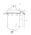
- the oil separator 3 includes a bottomed cylindrical case 11 and a lid 12 that seals the opening of the case.
- a drain discharge port 13 for discharging the drain liquid accumulated in the oil separator 3 is provided at the bottom of the case 11.
- a drain hose 14 used when taking out the drain liquid is connected to the drain outlet 13.
- the lid 12 is provided with a discharge port 16 for discharging clean air.
- An air discharge hose 20 that discharges clean air to the atmosphere is connected to the discharge port 16 via a discharge side coupling member 19.
- the lid 12 is provided with a mounting plate 29 for fixing the oil separator 3 to a body to be mounted such as a vehicle body.
- the lid 12 is provided with an inlet 15 for introducing the air discharged from the air dryer 2 in addition to the outlet 16.
- a hose that supplies air that has flowed out of the air dryer 2 is connected to the introduction port 15 via an introduction-side coupling member 18.
- the lid 12 has a covered cylindrical shape with the top vertically closed.
- Two baffle plates 21 are provided inside the lid 12 and in the vicinity of the inlet 15.
- the baffle plate 21 is erected so as to be orthogonal to the traveling direction of the purge air introduced from the introduction port 15.
- the lid 12 is formed with a communication portion 23 that communicates the inside of the case 11 with the discharge port 16.
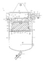
- a disc-shaped cover 25 is provided between the case 11 and the lid 12.
- the case 11, the cover 25, and the lid 12 have bolts 27 fastened to the through holes provided in the flange portion 26 of the case 11, the through holes provided in the cover 25, and the screw holes provided in the lid 12. Are fixed to each other.
- the space defined by the cover 25 and the lid 12 functions as the first expansion chamber 22.
- a communication hole 28 is formed at the center of the cover 25.
- a covered cylindrical housing member 30 is fixed to the bottom surface of the cover 25 with bolts 38.
- Flange portions 31 and 32 are formed at the upper edge portion and the lower edge portion of the housing member 30.
- the housing member 30 is fastened to the cover 25 by the bolt 38 passing through the flange portion 31.
- a space defined by the fastened upper surface of the housing member 30 and the cover 25 functions as the second expansion chamber 33.
- the communication hole 28 formed in the cover 25 communicates the first expansion chamber 22 and the second expansion chamber 33.
- a plurality of through holes 35 are formed in the central portion of the upper wall portion 34 of the housing member 30.
- the through holes 35 and the communication holes 28 of the cover 25 are formed at positions that do not face each other.
- a plurality of through holes 36 are formed at intervals in the circumferential direction on the lower end side of the side wall portion of the housing member 30.
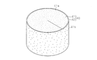
- the housing member 30 houses an oil catcher 40 that removes oil contained in the purge air.
- the oil catcher 40 includes a collision material 41 that is a first filter and a glass fiber filter 42 that is a second filter.
- the collision material 41 is made of a resin sponge (urethane foam) having a large number of air holes inside, and in the state of being accommodated in the accommodation member 30, has a cylindrical shape.
- the glass fiber filter 42 is formed in a sheet shape, and is wound around an outer peripheral surface 41 b as a second surface of the cylindrical collision material 41.
- the upper surface 41a as the first surface of the collision material 41 and the bottom surface are provided with a plate 43 in which a large number of through holes are formed to support the collision material 41.
- a disc-shaped support plate 45 that supports the oil catching portion 40 is fixed to the flange portion 32 formed at the lower edge of the housing member 30 by screws 46.
- the support plate 45 is formed to have substantially the same diameter as the inner diameter of the case 11.
- the support board 45 is formed with a plurality of through holes 47 through which liquid oil or the like captured by the oil capturing section 40 is dropped.
- a drain reservoir 48 serving as a reservoir for storing the drain liquid dropped through the through hole 47 is provided at the lower part of the case 11.
- the drain reservoir 48 is provided with a heater 49 for heating the accumulated drain liquid and evaporating water.
- the heater 49 controls heating by a thermostat (not shown).
- the collision material 41 is formed in a columnar shape by rounding so that both ends of a sponge formed in a rectangular parallelepiped shape are close to each other.
- the glass fiber filter 42 has a height and a width that can cover the entire outer peripheral surface 41 b that is a surface other than the flat surface and the bottom surface of the impact material 41 that is made cylindrical.
- the collision material 41 is accommodated inside the accommodation member 30 with the outer peripheral surface 41 b covered with the glass fiber filter 42.
- the impact material 41 and the glass fiber filter 42 wound around the impact material 41 may be accommodated in the accommodation member 30 in a state of being fixed to each other by an adhesive or the like, or may be accommodated in the accommodation member 30 in an unfixed state. May be.
- the thickness of the glass fiber filter 42 is smaller than the diameter of the collision material 41, and the volume of the collision material 41 is larger than the volume of the glass fiber filter 42.
- the ratio of the diameter of the impact material 41 and the thickness of the glass fiber filter 42 is adjusted for convenience. Or it can change suitably according to the factor by the side of a compressed air drying system, etc.
- This collision material 41 changes the air flow finely by the air holes in the sponge, thereby causing oil particles on the air flow to collide with each other due to inertial force.
- the oil particles captured by the collision material 41 are mostly oil particles having a relatively large diameter.
- the glass fiber filter 42 is a filter using glass fiber, for example, a glass fiber fixed to a base material such as a nonwoven fabric, or compression molding of glass fiber alone or glass fiber and other materials. Etc.
- the glass fiber filter 42 has a fiber diameter, a hole diameter, and a depth direction density capable of capturing minute oil particles that perform Brownian motion in compressed air.
- large-sized oil particles having a particle diameter of 1 ⁇ m or more are most efficiently captured using the inertial collision described above.
- the number of small diameter oil particles contained in compressed air is larger than that of large diameter oil particles.
- the small-diameter oil particles collide with gas molecules in the compressed air, thereby causing an irregular motion (Brownian motion) unrelated to the flow of the compressed air.
- the particle size of the oil particles that move irregularly is, for example, 50 nm or less, but is difficult to capture by the method using inertial collision, and the capture by contact with the glass fiber is efficient.
- oil particles having an intermediate particle diameter such as more than 50 nm and less than 1 ⁇ m can be captured by the impact material 41 and the glass fiber filter 42, although the efficiency is slightly reduced. That is, since the diameter of the oil particles with good capturing efficiency of the collision material 41 and the diameter of the oil particles with high capturing efficiency of the glass fiber filter 42 are different from each other, it is possible to capture oil particles in a wide diameter range as a whole. It becomes possible.
- the oil particles contained in the purge air have a relatively large number of small oil particles in terms of the number of particles as described above, but the total volume of large oil particles and the total of small oil particles are small.
- the volume ratio differs depending on the individual difference of the compressor 1 and the operating atmosphere (temperature, humidity, etc.).
- the collection performance of oil particles can be adjusted by changing the ratio of the volume of the collision material 41 and the volume of the glass fiber filter 42. Therefore, the size of the collision material 41, the thickness of the glass fiber filter 42, and the like are not limited to those described in FIGS. 4 and 5 and can be changed as appropriate.
- the volume of the glass fiber filter 42 can be made larger than the volume of the collision material 41.
- the purge air discharged from the air dryer 2 flows into the oil separator 3 from the inlet 15 as shown by the arrow direction in the figure.
- the purge air flowing in from the introduction port 15 collides with the baffle plate 21 and is then introduced into the first expansion chamber 22 to expand.
- the purge air expanded in the first expansion chamber 22 flows into the second expansion chamber 33 from the communication hole 28 formed in the cover 25 and expands. Further, the purge air flows from the through hole 35 in the upper wall portion 34 of the housing member 30 into the oil catching portion 40 in the housing member 30.
- the purge air that has flowed into the oil catcher 40 first passes through the impact material 41. Thereby, large-diameter oil particles contained in the purge air are captured. At this time, moisture contained in the purge air is also captured.
- the purge air in which the number of large diameter oil particles has been reduced flows into the glass fiber filter 42.
- the glass fiber filter 42 mainly captures oil particles having a relatively small diameter remaining in the purge air. At this time, moisture contained in the purge air is also captured.
- the liquid water and oil trapped by the oil trap 40 reach the upper surface of the support plate 45 through the oil trap 40, fall from the through hole 47 of the support plate 45, and are stored in the drain reservoir 48. .
- the drain liquid that is a liquid flows into the oil separator 3
- the drain liquid follows the same path as described above, passes through the oil trap 40, and falls to the drain reservoir 48.
- the drain liquid stored in the drain reservoir 48 is heated by the heater 49, and the water is evaporated.
- the drain liquid stored in the drain reservoir 48 is appropriately discharged through the drain hose 14.
- the clean air from which moisture and oil have been removed by the oil catcher 40 flows into the space provided between the housing member 30 and the case 11 from the through hole 36 on the side surface of the housing member 30.
- the air that has passed through the space passes through the communication hole 50 formed in the cover 25 and the communication portion 23 of the lid 12 and is discharged from the discharge port 16 (see FIG. 2 or FIG. 3).
- the collision material 41 mainly captures large-diameter oil particles
- the glass fiber filter 42 mainly captures small-diameter oil particles. Accordingly, as a whole, oil particles having a wide range of diameters can be captured, so that the oil content capture rate in the oil separator 3 can be improved.
- the oil capturing unit 40 includes the impact material 41 made of a sponge, the oil particles can be captured by causing the oil particles to inertially collide with the impact material 41. Further, since both the impact material 41 and the glass fiber filter 42 are materials that can be easily compressed, it is easy to press-fit the impact material 41 around which the glass fiber filter 42 is wound into the housing member 30.
- the oil catching section 40 includes a cylindrical collision material 41 and a pair of glass fiber filters 44 stacked on the upper surface 41 a and the bottom surface 41 c of the collision material 41.
- the glass fiber filter 44 has basically the same configuration as that of the first embodiment, and is formed in a circular shape.
- the upper glass fiber filter 44 is provided below the upper wall portion 34 of the housing member 30, and the lower glass fiber filter 44 is provided on the support board 45.
- the purge air in the second expansion chamber 33 flows into the housing member 30 through the through hole 35 of the upper wall portion 34 and first passes through the glass fiber filter 44. At this time, among the oil particles contained in the purge air, mainly small-diameter oil particles are captured. The purge air that has passed through the upper glass fiber filter 44 flows into the collision material 41. At this time, as in the first embodiment, oil particles having a large diameter are mainly captured.
- a portion of the purge air that has passed through the impact material 41 passes through the lower glass fiber filter 44 and then passes through the interior of the impact material 41 or between the impact material 41 and the side wall of the accommodation member 30 and is accommodated. It flows out of the housing member 30 from the through hole 36 in the side wall portion of the member 30. Further, a part of the purge air flows out of the housing member 30 without passing through the lower glass fiber filter 44.
- the clean air that has flowed out of the housing member 30 passes through the communication hole 50 formed in the cover 25 and the communication portion 23 of the lid 12 and is discharged from the discharge port 16.
- the liquid water and oil captured by the oil capturing unit 40 are stored in the drain storing unit 48 through the oil capturing unit 40.
- the effects (1), (3), and (4) can be obtained, and the following effects can be further obtained.
- each said embodiment can also be implemented with the following forms.
- the oil catcher 40 is disposed outside the first collision material 61 and a plurality of first collision materials 61 that are rounded so that both ends of the sponge formed in a rectangular parallelepiped shape are close to each other.
- a cylindrical second collision material 62 and a cylindrical third collision material 63 disposed outside the second collision material 62 may be provided.
- the second collision material 62 and the third collision material 63 are formed by rounding so that both ends of a rectangular parallelepiped or plate-like sponge are close to each other.
- a first glass fiber filter 71 wound around the outer periphery of the first collision material 61 is interposed between the first collision material 61 and the second collision material 62.
- a second glass fiber filter 72 wound around the outer periphery of the second collision material 62 is interposed between the second collision material 62 and the third collision material 63.
- a third glass fiber filter 73 is wound around the third collision material 63.
- the joint part 61a of the first collision material 61, the joint part 71a of the first glass fiber filter 71, the joint part 62a of the second collision material 62, the joint part 72a of the second glass fiber filter 72, and the joint part of the third collision material 63 63a and the joint part 73a of the third glass fiber filter 73 are provided at different positions in the circumferential direction of the oil catching part 40, respectively.
- the oil catcher 40 By displacing the joints 61a to 63a and 71a to 73a in this way, the oil catcher 40 is moved by the joints 61a to 63a and 71a to 73a regardless of the position where air flows into the oil catcher 40.
- the inflow to the inside is not obstructed and can always pass through the oil catching section 40.
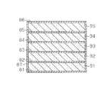
- a collision material made of sponge and a glass fiber filter may be laminated in the axial direction of the columnar oil capturing portion 40.
- five collision materials 91 to 95 may be interposed between six glass fiber filters 81 to 86.
- the glass fiber filter 87 may be wound around the outer periphery of the laminated body composed of the glass fiber filters 81 to 86 and the collision materials 91 to 95.
- the thickness of the glass fiber filter may be adjusted by winding a plurality of glass fiber filters around the impact material.
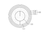
- the oil capturing unit 40 includes a first collision material 100 rolled up so that both ends of a sponge formed in a rectangular parallelepiped shape are close to each other, and a second collision material 101 wound around the outer periphery of the first collision material 100.
- Three glass fiber filters 102 to 104 are wound around the outer periphery of the second collision material 102.
- These glass fiber filters 102 to 104 may have the same characteristics such as weight per volume or may be different. If it does in this way, oil capture performance can be adjusted by adjusting the thickness of the layer of a glass fiber filter.
- a glass fiber filter may be provided between the first collision material 100 and the second collision material 102.
- a collision material made of a sponge and a glass fiber filter are laminated, and the thickness of the glass fiber filter is set to the number of laminated glass fiber filters. You may make it adjust with.
- three glass fiber filters 112 to 114 may be stacked on both axial surfaces of the pair of impact members 110 and 111, respectively. If it does in this way, oil capture performance can be adjusted by adjusting the thickness of the layer of a glass fiber filter.
- a glass fiber filter may be provided between the collision materials 110 and 111.
- the thickness of the glass fiber filter 42 is made smaller than the diameter of the cylindrical collision material 41, and the volume of the glass fiber filter 42 is made smaller than the volume of the collision material 41. It may be changed.
- the thickness of the glass fiber filter 42 may be larger than the diameter of the cylindrical collision material 41 according to factors on the compressed air drying system side, the oil trapping performance of the glass fiber filter 42, and the like.
- the volume of the glass fiber filter 42 may be larger than the volume of the material 41.
- the collision material 41 and the glass fiber filter 42 have a moisture trapping function, but the moisture trapping function is not necessarily required and the moisture may not be trapped.
- the collision material 41 may have an action of capturing oil particles charged by floating in the air by electrostatic force.
- the impact material is composed of the impact material 41, but may be composed of a metal material (for example, crushed aluminum) having a fine air hole inside, a baffle plate, or the like.
- the drain hose 14 is connected to the drain outlet 13 of the case 11.
- the drain hose 14 may be omitted, and a plug may be provided in the drain outlet 13 so that the drain outlet 13 can be directly discharged. Good.
- the first expansion chamber 22 and the second expansion chamber 33 are provided in the oil separator 3, but only one of the first expansion chamber 22 and the second expansion chamber 33 or only one expansion It may be a room.
- the number of heaters 49 can be changed as necessary, and may be omitted.
- -A glass fiber filter may be provided in the state which covers both the upper surface 41a (1st surface) and the outer peripheral surface 41b (2nd surface) of the collision material 41.
- the glass fiber filter may be provided in a state of covering all surfaces of the collision material 41.
- the glass fiber filter 44 provided in the bottom face 41c of the collision material 41 can also be abbreviate
- the configuration of the oil separator 3 other than the oil capturing unit 40 may be a configuration other than the above-described embodiments.
- a cartridge-type configuration in which the housing member 30 is fixed to the main body side including the case 11 by a screwing portion may be used.
- omitted the cover 25 may be sufficient.
- the connection structure between the introduction port 15 and the hose on the air dryer side and the connection structure between the discharge port 16 and the air discharge hose 20 may be other known connection structures.
- the air that has passed through the oil catcher 40 is caused to flow out of the housing member 30 through the through-hole 36 formed in the side wall portion of the housing member 30, but the bottom wall of the housing member 30 You may form the through-hole for making air flow out into a part.
- the second surface from which the air that has passed through the collision material 41 flows out becomes the bottom surface of the collision material 41.
- the oil capturing unit 40 is configured by a collision material made of urethane foam and a glass fiber filter, but may be a plurality of filters having different oil particle capturing rates depending on the particle diameter. That is, filters having different particle diameters with the highest capture rate may be used.
- the oil trap 40 may be composed of a plurality of collision materials having different particle diameters with a high capture rate.
- the oil separator 3 allows purge air to flow into the oil catcher 40 from above the oil catcher 40 in the vertical direction.
- Purge air may be allowed to flow in from the outer peripheral surface of the oil trap 40.
- a collision material having a high trapping rate for large-sized oil particles may be disposed on the surface of the oil trapping unit 40 where the purge air flows, according to the particle size distribution of the oil particles contained in the purge air.
- the oil separator 3 is provided in the exhaust system of the air dryer 2 that is downstream of the compressor 1 of the air system.
- the oil separator 3 may be provided downstream of the air system compressor 1 and upstream of the air dryer 2. If it does in this way, an oil component can be isolate
- Installation Plate 30 housing member 31 flange portion 32 flange portion 33 second expansion chamber 34 upper wall portion 35 through-hole 36 through-hole 40 oil catching portion 41 impact material 41a ... upper surface, 41b ... outer peripheral surface, 41c ... bottom surface, 42 ... glass fiber filter, 43 ... plate, 44 ... glass fiber filter, 45 ... support plate, 46 ... screw, 47 ... through hole, 48 ... drain reservoir, 49 ... He , 50 ... hole.
Abstract
Description
上記課題を解決するオイルセパレータは、油分を含む空気を気液分離し、油分を含む液体であるドレン液を回収するオイルセパレータにおいて、空気を導入する導入口と、空気に含まれる油分を捕捉するオイル捕捉部と、前記オイル捕捉部から流出したドレン液を貯留する貯留部と、前記油分を除去した空気を排出する排出口と、を備え、前記オイル捕捉部は、オイル粒子との衝突によって当該オイル粒子を捕捉する衝突材と、ガラス繊維フィルタとを有する。 Hereinafter, means for solving the above-described problems and the effects thereof will be described.
An oil separator that solves the above problems gas-liquid-separates air containing oil and collects the oil contained in the air in an oil separator that collects drain liquid that is liquid containing oil. An oil trap, a reservoir for storing the drain liquid flowing out of the oil trap, and a discharge port for discharging the air from which the oil has been removed, the oil trap being affected by collision with oil particles. A collision material for capturing oil particles and a glass fiber filter are included.
上記構成によれば、衝突材を通過した空気の殆どをガラス繊維フィルタに通過させることができるので、油分捕捉率をさらに高めることができる。 About this oil separator, it is preferable that the said glass fiber filter is formed in a sheet form, and covers the whole 2nd surface of the said collision material.
According to the said structure, since most of the air which passed the collision material can be passed through a glass fiber filter, an oil content capture | acquisition rate can further be improved.
上記構成によれば、衝突材はウレタンフォームからなるので、ガラス繊維フィルタとともにオイルセパレータの所定の位置に圧入しやすい。 In the oil separator, the collision material is preferably made of urethane foam.
According to the above configuration, since the impact material is made of urethane foam, it is easy to press-fit into the predetermined position of the oil separator together with the glass fiber filter.
このオイルセパレータについて、前記オイル捕捉部に備えられる複数の前記フィルタは、大きい粒子径のオイル粒子について高い捕捉率を有する第1のフィルタと、小さい粒子径のオイル粒子について高い捕捉率を有する第2のフィルタとを有し、前記オイル捕捉部は、前記導入口側に、前記第1のフィルタを備えることが好ましい。 According to the above configuration, the oil trapping part has a plurality of filters with different trapping rates depending on the particle diameter, so that it is possible to improve the oil trapping rate in the oil separator.
Regarding the oil separator, the plurality of filters provided in the oil trapping unit include a first filter having a high trapping rate for oil particles having a large particle size and a second filter having a high trapping rate for oil particles having a small particle size. It is preferable that the oil catcher includes the first filter on the inlet side.
以下、図1~図5を参照して、オイルセパレータを具体化した第1実施形態を説明する。 (First embodiment)
Hereinafter, a first embodiment in which an oil separator is embodied will be described with reference to FIGS.
図2に示されるように、オイルセパレータ3は、有底円筒状のケース11と、当該ケースの開口部を密閉する蓋12とを備えている。ケース11の底部には、オイルセパレータ3内に溜まったドレン液を排出するためのドレン排出口13が設けられている。このドレン排出口13には、ドレン液を取り出す際に使用するドレンホース14が接続されている。 Next, the configuration of the
As shown in FIG. 2, the
エアドライヤ2から排出されたパージエアは、図中矢印方向で示すように、導入口15からオイルセパレータ3に流入する。導入口15から流入したパージエアは、邪魔板21に衝突した後、第1膨張室22内に導入されて膨張する。 Next, the operation of the
The purge air discharged from the
(1)衝突材41によって、空気に含まれるオイル粒子のうち、主に大径のオイル粒子が捕捉され、ガラス繊維フィルタ42によって、主に小径のオイル粒子が捕捉される。従って、全体として、広域な径範囲のオイル粒子を捕捉することが可能になるため、オイルセパレータ3における油分捕捉率を向上させることができる。 According to the first embodiment, the following effects can be obtained.
(1) Of the oil particles contained in the air, the
次に、オイルセパレータの第2実施形態を、第1実施形態との相違点を中心に説明する。なお、本実施形態にかかるオイルセパレータは、第1実施形態のオイルセパレータに対してオイル捕捉部の構成のみが異なるため、それ以外の構成については説明を割愛する。 (Second Embodiment)
Next, a second embodiment of the oil separator will be described focusing on differences from the first embodiment. Note that the oil separator according to the present embodiment is different from the oil separator according to the first embodiment only in the configuration of the oil catching portion, and thus the description of other configurations is omitted.
第2膨張室33内のパージエアは、上壁部34の貫通孔35を介して、収容部材30内に流入し、まずガラス繊維フィルタ44を通過する。この際、パージエアに含まれるオイル粒子のうち、主に小径のオイル粒子が捕捉される。上側のガラス繊維フィルタ44を通過したパージエアは、衝突材41に流入する。この際、第1実施形態と同様に、主に大径のオイル粒子が捕捉される。 Next, the operation of this embodiment will be described.
The purge air in the
(5)ガラス繊維フィルタ44は、衝突材41のうち、パージエアが流入する上面41aに設けられるので、パージエアがオイル捕捉部40に流入した初期の段階で、パージエアの殆どをガラス繊維フィルタ44に通過させることができる。このため、小径のオイル粒子の数が低減されたパージエアを衝突材41に流入させることで、衝突材41の油分捕捉率を高めることができる。また1対のガラス繊維フィルタ44で衝突材41を挟むことによって、パージエアとガラス繊維との接触面積が増加するので、オイルセパレータ3の油分捕捉率をさらに高めることができる。 As described above, according to the present embodiment, the effects (1), (3), and (4) can be obtained, and the following effects can be further obtained.
(5) Since the
なお、上記各実施形態は、以下のような形態をもって実施することもできる。
・図8に示すように、オイル捕捉部40は、直方体形状に形成されたスポンジの両端を互いに近接させるように丸めた複数の第1衝突材61と、第1衝突材61の外側に配置された筒状の第2衝突材62と、その第2衝突材62の外側に配置された筒状の第3衝突材63とを備えていてもよい。第2衝突材62及び第3衝突材63は、直方体状又は板状のスポンジの両端を互いに近接させるように丸めて形成されている。第1衝突材61及び第2衝突材62の間には、第1衝突材61の外周に巻かれた第1ガラス繊維フィルタ71が介在している。また第2衝突材62及び第3衝突材63の間には、第2衝突材62の外周に巻かれた第2ガラス繊維フィルタ72が介在している。さらに、第3衝突材63の外側には第3ガラス繊維フィルタ73が巻かれている。第1衝突材61の接合部61a、第1ガラス繊維フィルタ71の接合部71a、第2衝突材62の接合部62a、第2ガラス繊維フィルタ72の接合部72a、第3衝突材63の接合部63a、第3ガラス繊維フィルタ73の接合部73aは、オイル捕捉部40の周方向においてそれぞれ異なる位置に設けられている。このように接合部61a~63a、71a~73aをずらすことによって、オイル捕捉部40に空気がいずれの位置から流入した場合であっても、接合部61a~63a、71a~73aによってオイル捕捉部40内への流入が妨害されず、必ずオイル捕捉部40内を通過することができる。 (Other embodiments)
In addition, each said embodiment can also be implemented with the following forms.
As shown in FIG. 8, the
・上記各実施形態では、衝突材を、衝突材41から構成したが、内部に細かい通気孔を有する金属材(例えばクラッシュドアルミ)や邪魔板等から構成してもよい。 The
In each of the above embodiments, the impact material is composed of the
・ガラス繊維フィルタは、衝突材41の上面41a(第1の面)及び外周面41b(第2の面)の両方を覆う状態で設けられてもよい。また、ガラス繊維フィルタは、衝突材41の全ての面を覆う状態で設けられてもよい。 In the above configuration, the number of
-A glass fiber filter may be provided in the state which covers both the
・オイル捕捉部40以外のオイルセパレータ3の構成は、上述した各実施形態以外の構成でもよい。例えば、収容部材30がケース11を含む本体側に螺合部によって固定される、カートリッジ式の構成であってもよい。また、カバー25を省略した構成でもよい。さらに、導入口15とエアドライヤ側のホースとの接続構造、排出口16と空気排出ホース20との接続構造は、他の公知の接続構造でもよい。 -In 2nd Embodiment, the
The configuration of the
Claims (7)
- 油分を含む空気を気液分離し、油分を含む液体であるドレン液を回収するオイルセパレータにおいて、
空気を導入する導入口と、
空気に含まれる油分を捕捉するオイル捕捉部と、
前記オイル捕捉部から流出したドレン液を貯留する貯留部と、
前記油分を除去した空気を排出する排出口と、を備え、
前記オイル捕捉部は、オイル粒子との衝突によって当該オイル粒子を捕捉する衝突材と、ガラス繊維フィルタとを有する
ことを特徴とするオイルセパレータ。 In an oil separator that gas-liquid separates air containing oil and collects drain liquid that is liquid containing oil,
An inlet for introducing air;
An oil catcher for catching oil contained in the air;
A reservoir for storing drain liquid that has flowed out of the oil catcher;
An exhaust port for discharging the air from which the oil has been removed,
The oil separator includes an impact material that captures oil particles by collision with oil particles, and a glass fiber filter. - 前記衝突材は、通気性を有し、空気が流入する第1の面、及び当該衝突材を通過した空気が流出する第2の面を備え、
前記ガラス繊維フィルタは、前記衝突材の第2の面に設けられる
請求項1に記載のオイルセパレータ。 The collision material has air permeability, and includes a first surface into which air flows and a second surface from which air that has passed through the collision material flows out,
The oil separator according to claim 1, wherein the glass fiber filter is provided on a second surface of the collision material. - 前記ガラス繊維フィルタは、シート状に形成され、前記衝突材の第2の面の全体を覆う請求項2に記載のオイルセパレータ。 The oil separator according to claim 2, wherein the glass fiber filter is formed in a sheet shape and covers the entire second surface of the collision material.
- 前記衝突材は、通気性を有し、空気が流入する第1の面、及び当該衝突材を通過した空気が排出される第2の面を備え、
前記ガラス繊維フィルタは、前記衝突材の第1の面に設けられる
請求項1~3のいずれか1項に記載のオイルセパレータ。 The impact material has air permeability, and includes a first surface into which air flows and a second surface from which air that has passed through the impact material is discharged,
The oil separator according to any one of claims 1 to 3, wherein the glass fiber filter is provided on a first surface of the collision material. - 前記衝突材は、ウレタンフォームからなる
請求項1~4のいずれか1項に記載のオイルセパレータ。 The oil separator according to any one of claims 1 to 4, wherein the collision material is made of urethane foam. - 排気を導入する導入口と、
排気に含まれる油分を捕捉するオイル捕捉部と、
前記オイル捕捉部から流出した油分を含むドレン液を貯留する貯留部と、
前記油分を除去した排気を排出する排出口と、を備え、
前記オイル捕捉部は、オイル粒子の粒子径に応じた捕捉率を有する複数のフィルタを有し、各フィルタは異なる捕捉率を有する
ことを特徴とするオイルセパレータ。 An inlet for introducing exhaust;
An oil catcher for catching oil contained in the exhaust;
A storage section for storing a drain liquid containing oil that has flowed out of the oil capturing section;
An exhaust port for discharging the exhaust gas from which the oil has been removed,
The oil separator has a plurality of filters having a capture rate corresponding to the particle diameter of oil particles, and each filter has a different capture rate. - 前記オイル捕捉部に備えられる複数の前記フィルタは、大きい粒子径のオイル粒子について高い捕捉率を有する第1のフィルタと、小さい粒子径のオイル粒子について高い捕捉率を有する第2のフィルタとを有し、
前記オイル捕捉部は、前記導入口側に、前記第1のフィルタを備える
ことを特徴とする請求項6に記載のオイルセパレータ。 The plurality of filters provided in the oil trapping unit include a first filter having a high trapping rate for oil particles having a large particle size and a second filter having a high trapping rate for oil particles having a small particle size. And
The oil separator according to claim 6, wherein the oil catcher includes the first filter on the inlet side.
Priority Applications (4)
| Application Number | Priority Date | Filing Date | Title |
|---|---|---|---|
| JP2016505361A JP6609545B2 (en) | 2014-02-28 | 2015-03-02 | Oil separator |
| US15/121,224 US10603619B2 (en) | 2014-02-28 | 2015-03-02 | Oil separator |
| DE112015001035.1T DE112015001035T5 (en) | 2014-02-28 | 2015-03-02 | oil separator |
| CN201580010147.1A CN106460598B (en) | 2014-02-28 | 2015-03-02 | System with compressor, air dryer and oil eliminator |
Applications Claiming Priority (2)
| Application Number | Priority Date | Filing Date | Title |
|---|---|---|---|
| JP2014038507 | 2014-02-28 | ||
| JP2014-038507 | 2014-02-28 |
Publications (1)
| Publication Number | Publication Date |
|---|---|
| WO2015129914A1 true WO2015129914A1 (en) | 2015-09-03 |
Family
ID=54009222
Family Applications (1)
| Application Number | Title | Priority Date | Filing Date |
|---|---|---|---|
| PCT/JP2015/056055 WO2015129914A1 (en) | 2014-02-28 | 2015-03-02 | Oil separator |
Country Status (5)
| Country | Link |
|---|---|
| US (1) | US10603619B2 (en) |
| JP (1) | JP6609545B2 (en) |
| CN (1) | CN106460598B (en) |
| DE (1) | DE112015001035T5 (en) |
| WO (1) | WO2015129914A1 (en) |
Cited By (3)
| Publication number | Priority date | Publication date | Assignee | Title |
|---|---|---|---|---|
| WO2016159109A1 (en) * | 2015-03-31 | 2016-10-06 | ナブテスコオートモーティブ 株式会社 | Compressed air drying device |
| GB2552986A (en) * | 2016-08-17 | 2018-02-21 | Nifco Inc | An oil separating device |
| CN112856506A (en) * | 2021-01-07 | 2021-05-28 | 宁波方太厨具有限公司 | Range hood, outdoor dining car using range hood and control method of range hood |
Families Citing this family (7)
| Publication number | Priority date | Publication date | Assignee | Title |
|---|---|---|---|---|
| EP3492157B1 (en) * | 2017-11-30 | 2024-04-10 | GF Machining Solutions AG | Device and method for extracting oil particles from an air flow |
| US10583391B2 (en) * | 2017-12-18 | 2020-03-10 | Bendix Commercial Vehicle Systems Llc | Absorbent apparatus for an air dryer purge air cleaner and method of producing the same |
| US10807582B2 (en) * | 2018-03-27 | 2020-10-20 | Bendix Commercial Vehicle Systems Llc | Effluent processing apparatus and method for a vehicle air brake charging system |
| CN110604994B (en) * | 2019-09-27 | 2021-12-31 | 湖北金顿电气有限公司 | Dustproof electrical system of cotton workshop of glass |
| CN110819389A (en) * | 2019-12-23 | 2020-02-21 | 河南电研新能源科技有限公司 | Biomass gasification production equipment and production method taking livestock and poultry manure as raw material |
| KR20220056021A (en) * | 2020-10-27 | 2022-05-04 | 삼성전자주식회사 | particulate matter collector |
| EP4001600A1 (en) * | 2020-11-20 | 2022-05-25 | Volvo Truck Corporation | A method for diagnosing a part of a crank case ventilation system |
Citations (6)
| Publication number | Priority date | Publication date | Assignee | Title |
|---|---|---|---|---|
| JPS5735819U (en) * | 1980-08-07 | 1982-02-25 | ||
| JPS63232815A (en) * | 1987-03-20 | 1988-09-28 | Hitachi Ltd | Oil separator element of lubricated rotary compressor |
| JPH1136841A (en) * | 1997-07-25 | 1999-02-09 | Honda Motor Co Ltd | Blow-by gas treating device for engine |
| JP2001140759A (en) * | 1999-11-18 | 2001-05-22 | Sanyo Electric Co Ltd | Oil separator and very low temperature refrigerating device equipped with oil separator |
| JP2011047306A (en) * | 2009-08-26 | 2011-03-10 | Toyota Boshoku Corp | Oil mist separator |
| JP2013094699A (en) * | 2011-10-28 | 2013-05-20 | Toyota Boshoku Corp | Filter medium for mist separator |
Family Cites Families (19)
| Publication number | Priority date | Publication date | Assignee | Title |
|---|---|---|---|---|
| US3554700A (en) * | 1968-05-06 | 1971-01-12 | Scientific Industries | Method for obtaining a known volume of liquid and absorption apparatus therefor |
| US3747773A (en) * | 1971-09-27 | 1973-07-24 | R Jackson | Dual gluing filter |
| GB1566264A (en) * | 1976-04-23 | 1980-04-30 | Whatman Reeve Angel Ltd | Inside-to-outside flow filter tube and method of manufacturing same |
| DE7726666U1 (en) * | 1977-08-27 | 1978-05-18 | Filterwerk Mann & Hummel Gmbh, 7140 Ludwigsburg | OIL SEPARATOR FOR AIR |
| JPS57181913A (en) * | 1981-05-02 | 1982-11-09 | Honda Motor Co Ltd | Heater for lubricating oil of internal combustion engine |
| IT1179369B (en) * | 1984-05-15 | 1987-09-16 | Ital Idee Srl | MULTIPLE FILTER GROUP, ESPECIALLY FOR VENTILATION AND AIR CONDITIONING SYSTEMS FOR MOTOR VEHICLES AND CLOSED ENVIRONMENTS, EQUIPPED WITH MEANS OF CONTROL OF EFFICIENCY |
| SE9000650L (en) * | 1989-02-28 | 1990-08-29 | Asahi Optical Co Ltd | Separation of cells or viruses |
| JP2726382B2 (en) * | 1993-12-13 | 1998-03-11 | 俊和 河合 | Design method of suction device for local ventilation |
| US7332010B2 (en) * | 2002-04-16 | 2008-02-19 | Tm Industrial Supply, Inc. | High pressure filter/separator and locking mechanism |
| DE10224224A1 (en) * | 2002-05-31 | 2003-12-11 | Mann & Hummel Filter | Filter element, in particular for filtering liquids |
| DE102004016742B3 (en) * | 2004-04-05 | 2005-09-15 | Dichtungstechnik G. Bruss Gmbh & Co. Kg | Automotive blow-by gas manifold oil separator has constructed zone with heated sidewall and fleece oil trap |
| US7686859B2 (en) * | 2005-08-04 | 2010-03-30 | Johnson Controls Technology Company | Coalescing filter element with drainage mechanism |
| CN201221882Y (en) * | 2008-05-23 | 2009-04-15 | 上海富田空调冷冻设备有限公司 | Oil separator for refrigerating device |
| DE102010011512A1 (en) * | 2010-03-12 | 2011-09-15 | Mann+Hummel Gmbh | Filter medium of a filter element, filter element and method for producing a filter medium |
| JP2013234632A (en) | 2012-05-10 | 2013-11-21 | Nabtesco Automotive Corp | Oil separator |
| EP2889484B1 (en) | 2012-07-02 | 2020-06-03 | Nabtesco Automotive Corporation | Oil separator |
| JP2014024030A (en) | 2012-07-27 | 2014-02-06 | Nabtesco Automotive Corp | Compression air dryer |
| JP6076032B2 (en) * | 2012-10-24 | 2017-02-08 | 昭和電機株式会社 | Oil mist removal device |
| DE102014003314A1 (en) * | 2014-03-08 | 2015-09-10 | Hydac Fluidcarecenter Gmbh | Method for adapting a filter medium to specifiable parameters and preferably a filter medium produced by this method |
-
2015
- 2015-03-02 US US15/121,224 patent/US10603619B2/en active Active
- 2015-03-02 WO PCT/JP2015/056055 patent/WO2015129914A1/en active Application Filing
- 2015-03-02 CN CN201580010147.1A patent/CN106460598B/en active Active
- 2015-03-02 JP JP2016505361A patent/JP6609545B2/en active Active
- 2015-03-02 DE DE112015001035.1T patent/DE112015001035T5/en active Pending
Patent Citations (6)
| Publication number | Priority date | Publication date | Assignee | Title |
|---|---|---|---|---|
| JPS5735819U (en) * | 1980-08-07 | 1982-02-25 | ||
| JPS63232815A (en) * | 1987-03-20 | 1988-09-28 | Hitachi Ltd | Oil separator element of lubricated rotary compressor |
| JPH1136841A (en) * | 1997-07-25 | 1999-02-09 | Honda Motor Co Ltd | Blow-by gas treating device for engine |
| JP2001140759A (en) * | 1999-11-18 | 2001-05-22 | Sanyo Electric Co Ltd | Oil separator and very low temperature refrigerating device equipped with oil separator |
| JP2011047306A (en) * | 2009-08-26 | 2011-03-10 | Toyota Boshoku Corp | Oil mist separator |
| JP2013094699A (en) * | 2011-10-28 | 2013-05-20 | Toyota Boshoku Corp | Filter medium for mist separator |
Cited By (6)
| Publication number | Priority date | Publication date | Assignee | Title |
|---|---|---|---|---|
| WO2016159109A1 (en) * | 2015-03-31 | 2016-10-06 | ナブテスコオートモーティブ 株式会社 | Compressed air drying device |
| GB2552986A (en) * | 2016-08-17 | 2018-02-21 | Nifco Inc | An oil separating device |
| CN109642483A (en) * | 2016-08-17 | 2019-04-16 | 株式会社利富高 | Oil separating device |
| GB2552986B (en) * | 2016-08-17 | 2020-09-16 | Nifco Inc | A device for separating oil from a blow-by gas |
| CN112856506A (en) * | 2021-01-07 | 2021-05-28 | 宁波方太厨具有限公司 | Range hood, outdoor dining car using range hood and control method of range hood |
| CN112856506B (en) * | 2021-01-07 | 2022-04-19 | 宁波方太厨具有限公司 | Range hood, outdoor dining car using range hood and control method of range hood |
Also Published As
| Publication number | Publication date |
|---|---|
| US10603619B2 (en) | 2020-03-31 |
| CN106460598A (en) | 2017-02-22 |
| JPWO2015129914A1 (en) | 2017-03-30 |
| US20170021300A1 (en) | 2017-01-26 |
| JP6609545B2 (en) | 2019-11-20 |
| DE112015001035T5 (en) | 2016-12-22 |
| CN106460598B (en) | 2019-07-26 |
Similar Documents
| Publication | Publication Date | Title |
|---|---|---|
| JP6609545B2 (en) | Oil separator | |
| JP6845284B2 (en) | Compressed air drying system | |
| JP2016186311A (en) | Oil separator | |
| WO2013129495A1 (en) | Oil separator | |
| JP6780059B2 (en) | Compressed air dryer | |
| JP6247278B2 (en) | Oil separator and air system | |
| US8858669B2 (en) | Oil coalescing filter | |
| JP6576911B2 (en) | Compressed air drying system and method for regenerating compressed air drying system | |
| WO2015129856A1 (en) | Oil separator and drain discharge system | |
| JP5973185B2 (en) | Oil separator | |
| JP6567323B2 (en) | Oil separator | |
| JP6779962B2 (en) | Compressed air dryer | |
| JP6247351B2 (en) | Oil separator | |
| CN107708841B (en) | Compressed air drying device | |
| JP5973186B2 (en) | Oil separator | |
| JP2016190207A (en) | Compressed-air drier | |
| JP2013173124A (en) | Oil separator | |
| JP2013173125A (en) | Oil separator |
Legal Events
| Date | Code | Title | Description |
|---|---|---|---|
| 121 | Ep: the epo has been informed by wipo that ep was designated in this application |
Ref document number: 15756062 Country of ref document: EP Kind code of ref document: A1 |
|
| WWE | Wipo information: entry into national phase |
Ref document number: 15121224 Country of ref document: US |
|
| ENP | Entry into the national phase |
Ref document number: 2016505361 Country of ref document: JP Kind code of ref document: A |
|
| WWE | Wipo information: entry into national phase |
Ref document number: 112015001035 Country of ref document: DE |
|
| 122 | Ep: pct application non-entry in european phase |
Ref document number: 15756062 Country of ref document: EP Kind code of ref document: A1 |