WO2015129636A1 - 透光性カバー及び照明器具 - Google Patents
透光性カバー及び照明器具 Download PDFInfo
- Publication number
- WO2015129636A1 WO2015129636A1 PCT/JP2015/055077 JP2015055077W WO2015129636A1 WO 2015129636 A1 WO2015129636 A1 WO 2015129636A1 JP 2015055077 W JP2015055077 W JP 2015055077W WO 2015129636 A1 WO2015129636 A1 WO 2015129636A1
- Authority
- WO
- WIPO (PCT)
- Prior art keywords
- shape
- translucent cover
- light source
- source unit
- convex
- Prior art date
Links
Images

Classifications
-
- F—MECHANICAL ENGINEERING; LIGHTING; HEATING; WEAPONS; BLASTING
- F21—LIGHTING
- F21V—FUNCTIONAL FEATURES OR DETAILS OF LIGHTING DEVICES OR SYSTEMS THEREOF; STRUCTURAL COMBINATIONS OF LIGHTING DEVICES WITH OTHER ARTICLES, NOT OTHERWISE PROVIDED FOR
- F21V3/00—Globes; Bowls; Cover glasses
- F21V3/02—Globes; Bowls; Cover glasses characterised by the shape
-
- F—MECHANICAL ENGINEERING; LIGHTING; HEATING; WEAPONS; BLASTING
- F21—LIGHTING
- F21S—NON-PORTABLE LIGHTING DEVICES; SYSTEMS THEREOF; VEHICLE LIGHTING DEVICES SPECIALLY ADAPTED FOR VEHICLE EXTERIORS
- F21S8/00—Lighting devices intended for fixed installation
- F21S8/03—Lighting devices intended for fixed installation of surface-mounted type
- F21S8/031—Lighting devices intended for fixed installation of surface-mounted type the device consisting essentially only of a light source holder with an exposed light source, e.g. a fluorescent tube
-
- F—MECHANICAL ENGINEERING; LIGHTING; HEATING; WEAPONS; BLASTING
- F21—LIGHTING
- F21V—FUNCTIONAL FEATURES OR DETAILS OF LIGHTING DEVICES OR SYSTEMS THEREOF; STRUCTURAL COMBINATIONS OF LIGHTING DEVICES WITH OTHER ARTICLES, NOT OTHERWISE PROVIDED FOR
- F21V17/00—Fastening of component parts of lighting devices, e.g. shades, globes, refractors, reflectors, filters, screens, grids or protective cages
-
- F—MECHANICAL ENGINEERING; LIGHTING; HEATING; WEAPONS; BLASTING
- F21—LIGHTING
- F21V—FUNCTIONAL FEATURES OR DETAILS OF LIGHTING DEVICES OR SYSTEMS THEREOF; STRUCTURAL COMBINATIONS OF LIGHTING DEVICES WITH OTHER ARTICLES, NOT OTHERWISE PROVIDED FOR
- F21V3/00—Globes; Bowls; Cover glasses
-
- F—MECHANICAL ENGINEERING; LIGHTING; HEATING; WEAPONS; BLASTING
- F21—LIGHTING
- F21K—NON-ELECTRIC LIGHT SOURCES USING LUMINESCENCE; LIGHT SOURCES USING ELECTROCHEMILUMINESCENCE; LIGHT SOURCES USING CHARGES OF COMBUSTIBLE MATERIAL; LIGHT SOURCES USING SEMICONDUCTOR DEVICES AS LIGHT-GENERATING ELEMENTS; LIGHT SOURCES NOT OTHERWISE PROVIDED FOR
- F21K9/00—Light sources using semiconductor devices as light-generating elements, e.g. using light-emitting diodes [LED] or lasers
- F21K9/20—Light sources comprising attachment means
-
- F—MECHANICAL ENGINEERING; LIGHTING; HEATING; WEAPONS; BLASTING
- F21—LIGHTING
- F21V—FUNCTIONAL FEATURES OR DETAILS OF LIGHTING DEVICES OR SYSTEMS THEREOF; STRUCTURAL COMBINATIONS OF LIGHTING DEVICES WITH OTHER ARTICLES, NOT OTHERWISE PROVIDED FOR
- F21V15/00—Protecting lighting devices from damage
- F21V15/01—Housings, e.g. material or assembling of housing parts
- F21V15/015—Devices for covering joints between adjacent lighting devices; End coverings
-
- F—MECHANICAL ENGINEERING; LIGHTING; HEATING; WEAPONS; BLASTING
- F21—LIGHTING
- F21Y—INDEXING SCHEME ASSOCIATED WITH SUBCLASSES F21K, F21L, F21S and F21V, RELATING TO THE FORM OR THE KIND OF THE LIGHT SOURCES OR OF THE COLOUR OF THE LIGHT EMITTED
- F21Y2103/00—Elongate light sources, e.g. fluorescent tubes
- F21Y2103/10—Elongate light sources, e.g. fluorescent tubes comprising a linear array of point-like light-generating elements
-
- F—MECHANICAL ENGINEERING; LIGHTING; HEATING; WEAPONS; BLASTING
- F21—LIGHTING
- F21Y—INDEXING SCHEME ASSOCIATED WITH SUBCLASSES F21K, F21L, F21S and F21V, RELATING TO THE FORM OR THE KIND OF THE LIGHT SOURCES OR OF THE COLOUR OF THE LIGHT EMITTED
- F21Y2115/00—Light-generating elements of semiconductor light sources
- F21Y2115/10—Light-emitting diodes [LED]
Definitions
- This invention relates to a translucent cover for a lighting fixture.
- the surface of the LED light source unit (arch-shaped diffusion cover) is curved, so that it is difficult to grasp and attach / detach. .
- An object of the present invention is to provide a structure that is easy to grip on the surface of an LED light source unit, and to easily remove the LED light source unit from the instrument body.
- the translucent cover of this invention is in a translucent cover having a translucent shape used for lighting equipment, A cover part having an arch shape extending over the longitudinal shape; A first side portion that rises in a wall shape from one end portion along the longitudinal direction of the longitudinal shape of the cover portion; A second side portion that rises in a wall shape from the other end portion along the longitudinal direction of the cover portion,
- the first side is At least one of a first side concave portion that is recessed inward toward the second side portion and a first side convex portion that is convex outward with respect to the second side portion is formed
- the second side is At least one of a second side concave portion that is recessed inward toward the second side portion and a second side convex portion that is convex outward with respect to the first side portion is formed. It is characterized by.
- the surface of the LED light source unit can be provided with a structure that can be easily gripped, and the LED light source unit can be easily detached from the instrument body.
- FIG. 3 is a perspective view and a side view of the lighting apparatus of the first embodiment.
- the perspective view and side view which show the state which removed the light source part from the instrument main body of FIG.
- the disassembled perspective view of the instrument main body of FIG. 3 is a sectional view taken along line BB in FIG.
- FIG. 2 is a cross-sectional view taken along the line AA in FIG.
- FIG. 5 is a diagram corresponding to FIG. 4 in the second embodiment.
- FIG. 6 is a diagram corresponding to FIG. 5 in the second embodiment.
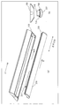
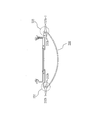
- FIG. 1 is a perspective view ((a) of FIG. 1) of the lighting fixture 1000 of Embodiment 1, and a right side view ((b) of FIG. 1) in the perspective view.
- the left side view in the perspective view is the same as the right side view.
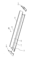
- 2 is a perspective view (FIG. 2 (a)) and right side view (FIG. 2 (b)) showing a state in which the light source unit 200 (sometimes referred to as a light source unit) is removed from the instrument main body 100 of FIG. ).
- the left side view is the same as the right side view.
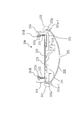
- FIG. 3 is an exploded perspective view showing a state in which the instrument main body 100 of FIG. 2 is disassembled into a main body 110 and left and right end plates 120.
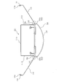
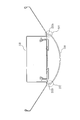
- FIG. 4 is a cross-sectional view (cross-section BB of FIG. 2A) showing a cross section of the light source section of FIG.
- FIG. 5 is a cross-sectional view of the lighting apparatus 1000 according to Embodiment 1 (AA cross section in FIG. 1A).
- the lighting fixture 1000 includes a fixture main body 100 and a light source unit 200 that can be attached to and detached from the fixture main body 100.
- the instrument main body 100 includes a main body 110 and left and right end plates 120 attached to both ends of the main body 110.
- the end plate 120-1 and the end plate 120-2 have the same shape.
- the main body 110 is formed by bending to form a concave portion 111 in which the light source unit 200 is accommodated, and formed at both ends of the concave portion 111, and the cover-side instrument main body contact portion 236 of the light source unit 200.
- the left and right contact portions 112 that contact each other, the respective inclined portions 113 that form inclined surfaces at the ends of the left and right contact portions 112, the upright portions 114 that are formed by bending from the end portions of the inclined portions 113, and the upright portions 114, and a curled portion 115c formed by being bent in a curled shape from an end portion of the 114.
- the concave portion 111 includes a concave top plate 111a that forms a ceiling on the side opposite to the opening side where the light source unit 200 is mounted, and two concave side walls 111b that form side plates on both sides of the concave top plate 111a. Is provided. Although not shown, the recess top plate 111a has an attachment portion (attachment hole) for attachment to an attachment portion such as a ceiling.
- End plate 120 The end plate 120 has a shape that closes the end of the main body 110, and has a trapezoidal shape in this embodiment.
- the end plate 120 is a part that is attached to the end of the main body 110 and has an important role as a reinforcing member for maintaining the shape of the main body 110 in addition to improving the design of the outer shape of the instrument main body 100. is there.
- the light source unit 200 includes an LED substrate 210 on which a plurality of LEDs are arranged, a frame 220 to which the LED substrate 210 is fixed, and a translucent translucent cover 230 that covers the LED substrate 210.
- the lighting fixture 1000 has a longitudinal shape, and the main body 110, the light source unit 200, the translucent cover 230, and the like also have a longitudinal shape.
- the light source unit 200 is attached to the instrument main body 100 in a state where the LED substrate 210, the frame 220, and the translucent cover 230 are integrated (FIG. 5).
- the LED substrate 210 includes a substrate 211 and a plurality of LEDs 212 mounted on the substrate 211.
- the LED board 210 has a longitudinal shape as shown in FIG. 1A, and a plurality of LEDs 212 are linearly arranged in one or more rows along the longitudinal shape.
- the frame 220 is detachably engaged with a main body side engaging portion (not shown) of the main body portion 110 by a frame side engaging portion (not shown) of the frame 220.
- the frame 220 has an opening on the upper surface and a cross-sectional shape of “U”.
- the main body 110 of FIG. 3 and the translucent cover 230 shown in FIG. It is a longitudinal shape with the same length. As shown in FIG.
- the frame 220 includes a frame-side flat portion 221 that is an elongated rectangular flat plate to which the LED substrate 210 is attached, a side plate 222 that forms each side of the frame-side flat portion 221, and an end of each side plate 222.
- a curled portion 222c that is curled at the portion is provided.
- the translucent cover 230 diffuses and transmits the light emitted from the LEDs 212 attached to the LED substrate 210.
- the translucent cover 230 has an arch shape in cross section. As shown in FIG. 4, the translucent cover 230 includes left and right attachment portions 231, left and right side portions 232, a curved surface portion 233 (cover portion), and left and right claw portions 234.
- Each attachment portion 231 presses the LED mounting surface of the LED substrate 210 at the end thereof, thereby pressing the back surface of the LED substrate 210 against the frame-side flat portion 221.
- the side portion 232 rises from each attachment portion 231. 4 and 5, the left side 232 is referred to as a first side 232, and the right side 232 is referred to as a second side 232.
- the 1st side part 232 and the 2nd side part 232 stand in wall shape from each both ends along the longitudinal direction of the curved surface part 233.
- FIG. (3) The curved surface portion 233 has an arch shape formed by a curved surface that protrudes outward so as to connect the side portions 232.
- the claw portion 234 stands on the wall in the direction opposite to the side portion 232 and is formed over the longitudinal direction of the translucent cover 230.
- a claw tip end 234 ⁇ / b> R that is a tip of the claw 234 is bent into an R shape so as to engage with the curl portion 222 c of the side plate 222.
- the side portion 232 has a hooking groove 232 a (concave portion) that forms a concave cross section that is smoothly recessed from the outside to the inside of the translucent cover 230.
- the term “groove” is because the hooking groove 232a is formed over the longitudinal direction of the translucent cover 230 (FIG. 2A).
- the hook groove 232a of the first side portion 232 is a first side recess
- the hook groove 232a of the second side portion 232 is a second side recess.
- the first side recess and the second side recess have a groove shape.
- the operator can easily remove the light source unit 200 from the instrument main body 100 without slipping by hooking a finger on the hooking groove 232a and gripping the side portions 232 on both sides.
- the hooking groove 232a makes it easier for a finger to be caught when the corner portion 232a-1 having a sharp tip is formed in the outer shell portion in the translucent cover 230, and the light source portion 200 is further detached from the instrument body 100. It becomes easy.
- FIG. The second embodiment is a modification of the side part 232 of the first embodiment.
- the description of the same structure as that of the first embodiment is omitted, and only the characteristic part of the second embodiment is described.
- FIG. 6 is a cross-sectional view showing a cross section of the light source unit 200 of the second embodiment
- FIG. 7 is a cross-sectional view showing a cross section of the lighting fixture 1000 of the second embodiment. 6 and 7 correspond to FIGS. 4 and 5 of the first embodiment.
- the side part 232 of the first embodiment has a hooking groove 232a that forms a concave cross section that is smoothly recessed from the outside to the inside of the translucent cover 230.
- the side part 232 of the second embodiment has a hooking convex part 232b that is formed to project in a convex shape in the outer direction of the translucent cover 230.
- the hooking convex part 232b is formed over the longitudinal direction of the translucent cover 230 similarly to the hooking groove 232a. 6 and 7, the left side 232 is referred to as a first side 232, and the right side 232 is referred to as a second side 232.
- the hook convex portion 232b of the first side portion 232 is a first side convex portion
- the hook convex portion 232b of the second side portion 232 is a second side convex portion.
- the first side convex portion and the second side convex portion have a protruding shape.
- this hooking convex part 232b may also be formed as a corner part 232b-1 with a pointed tip of the hooking convex part 232b that becomes the outer shell part of the translucent cover 230.
- the hook groove 232a of Embodiment 1 and the hook convex part 232b of Embodiment 2 were formed over the full length of the longitudinal direction of the translucent cover 230 was demonstrated, it is an example.
- the hook groove 232a and the hook protrusion 232b may not be formed over the entire length in the longitudinal direction. It may be partially formed in the longitudinal direction of the translucent cover 230.
- the hooking groove is described, and in the second embodiment, the hooking protrusion is described.
- both the hooking groove and the hooking protrusion may be formed.
- instrument body 110 body part, 111 recess, 111a recess top plate, 111b recess side wall part, 112 contact part, 113 inclined part, 114 upright part, 115c curl part, 120, 120-1, 120-2 end plate, 200
- Light source part 210 LED board, 211 board, 212 LED, 220 frame, 221 frame side flat part, 222 side plate, 222c curl part, 230 translucent cover, 231 mounting part, 232 side part, 232a hook groove, 232b pull Hanging convex part, 233 curved surface part, 234 claw part, 234R claw tip end part, 236 cover side apparatus body contact part, 1000 lighting apparatus.
Landscapes
- Engineering & Computer Science (AREA)
- General Engineering & Computer Science (AREA)
- Physics & Mathematics (AREA)
- Microelectronics & Electronic Packaging (AREA)
- Optics & Photonics (AREA)
- Non-Portable Lighting Devices Or Systems Thereof (AREA)
- Securing Globes, Refractors, Reflectors Or The Like (AREA)
- Radiation-Therapy Devices (AREA)
- Fastening Of Light Sources Or Lamp Holders (AREA)
Abstract
LED光源ユニットの表面に、把持しやすい構造を設け、器具本体からLED光源ユニットを外しやすくする。透光性カバー(230)は、アーチ形状が長手形状にわたって続く曲面部(233)、曲面部(233)の長手形状の長手方向に沿った一方の端部から壁形状に起立する側部(232)と、曲面部(233)の長手方向に沿った他方の端部から壁形状に起立するもう一方の側部(232)とを備える。側部(232)は、内側に凹形状に凹む引掛け溝(232a)が形成されている。
Description
この発明は照明器具の透光性カバーに関する。
直線状かつ断面形状がアーチ形状のLED光源ユニットを着脱可能に器具本体に取り付ける技術がある。(例えば、特許文献1参照。)
しかしながら、直線状かつ断面形状がアーチ形状のLED光源ユニットを器具本体から外すとき、LED光源ユニット(アーチ形状の拡散カバー)の表面は曲面なため、把持し難く、着脱がし難いという課題があった。
本発明は、LED光源ユニットの表面に、把持しやすい構造を設け、器具本体からLED光源ユニットを外しやすくすることを目的とする。
この発明の透光性カバーは、
照明器具に使用される透光性を有する長手形状の透光性カバーにおいて、
アーチ形状が前記長手形状にわたって続くカバー部と、
前記カバー部の前記長手形状の長手方向に沿った一方の端部から壁形状に起立する第1の側部と、
前記カバー部の前記長手方向に沿った他方の端部から壁形状に起立する第2の側部と
を備え、
前記第1の側部は、
前記第2の側部に向かって内側に凹形状に凹む第1側凹部と、前記第2の側部に対して外側に凸となる第1側凸部との少なくともいずれかが形成され、
前記第2の側部は、
前記第2の側部に向かって内側に凹形状に凹む第2側凹部と、前記第1の側部に対して外側に凸となる第2側凸部との少なくともいずれかが形成されたことを特徴とする。
本発明によれば、LED光源ユニットの表面に、把持しやすい構造を設け、器具本体からLED光源ユニットを外しやすくすることができる。
実施の形態1.
図1は、実施の形態1の照明器具1000の斜視図(図1の(a))、斜視図における右側面図(図1の(b))である。斜視図における左側面図は右側面図と同様である。図2は、図1の器具本体100から光源部200(光源ユニットと呼ばれることもある)を外した状態を示す斜視図(図2の(a))、右側面図(図2の(b))である。左側面図は右側面図と同様である。図3は、図2の器具本体100を本体部110と左右の端板120とに分解した状態を示す分解斜視図である。
図1は、実施の形態1の照明器具1000の斜視図(図1の(a))、斜視図における右側面図(図1の(b))である。斜視図における左側面図は右側面図と同様である。図2は、図1の器具本体100から光源部200(光源ユニットと呼ばれることもある)を外した状態を示す斜視図(図2の(a))、右側面図(図2の(b))である。左側面図は右側面図と同様である。図3は、図2の器具本体100を本体部110と左右の端板120とに分解した状態を示す分解斜視図である。
図4は、図2の光源部の断面を示す断面図(図2の(a)のB-B断面)である。図5は、実施の形態1の照明器具1000の断面図(図1の(a)のA-A断面)である。
(照明器具1000)
図2のように、照明器具1000は、器具本体100と、器具本体100に着脱可能な光源部200とを備える。
図2のように、照明器具1000は、器具本体100と、器具本体100に着脱可能な光源部200とを備える。
(器具本体100)
図3のように、器具本体100は、本体部110と、本体部110の両端に取り付けられる左右の端板120とを備える。図面左側の端板120-1、図面右側の端板120-2として区別する。特に区別の必要がない場合は端板120と記す。端板120-1と端板120-2とは同じ形状である。
図3のように、器具本体100は、本体部110と、本体部110の両端に取り付けられる左右の端板120とを備える。図面左側の端板120-1、図面右側の端板120-2として区別する。特に区別の必要がない場合は端板120と記す。端板120-1と端板120-2とは同じ形状である。
(本体部110)
図3、図5のように、本体部110は、折り曲げ形成され、光源部200が収納される凹部111と、凹部111の両端に形成され、光源部200のカバー側器具本体当接部236と接触する左右の接触部112と、左右の接触部112の端部に傾斜面を形成するそれぞれの傾斜部113と、傾斜部113の端部から折り曲げられて形成される立上部114と、立上部114の端部からカール状に曲げられて形成されるカール部115cと、を備える。図5のように、凹部111は、光源部200が装着される開口側と反対側において天井をなす凹部天板111aと、凹部天板111aの両側でそれぞれ側板をなす2つの凹部側壁部111bとを備える。凹部天板111aは、図示しないが、天井などの被取付部に取り付けるための取付部(取付穴)を有する。
図3、図5のように、本体部110は、折り曲げ形成され、光源部200が収納される凹部111と、凹部111の両端に形成され、光源部200のカバー側器具本体当接部236と接触する左右の接触部112と、左右の接触部112の端部に傾斜面を形成するそれぞれの傾斜部113と、傾斜部113の端部から折り曲げられて形成される立上部114と、立上部114の端部からカール状に曲げられて形成されるカール部115cと、を備える。図5のように、凹部111は、光源部200が装着される開口側と反対側において天井をなす凹部天板111aと、凹部天板111aの両側でそれぞれ側板をなす2つの凹部側壁部111bとを備える。凹部天板111aは、図示しないが、天井などの被取付部に取り付けるための取付部(取付穴)を有する。
(端板120)
端板120は、本体部110の端部を塞ぐ形状をしており、この実施の形態においては、台形状をなしている。端板120は、本体部110の端部に取り付けられて、器具本体100の外形の意匠性を向上させるほかに、本体部110の形状を維持するための補強部材として重要な役割を持つ部品である。
端板120は、本体部110の端部を塞ぐ形状をしており、この実施の形態においては、台形状をなしている。端板120は、本体部110の端部に取り付けられて、器具本体100の外形の意匠性を向上させるほかに、本体部110の形状を維持するための補強部材として重要な役割を持つ部品である。
(光源部200)
図4のように、光源部200は、複数のLEDが配置されたLED基板210、LED基板210が固定されるフレーム220、LED基板210を覆う透光性の透光性カバー230を備える。照明器具1000は長手形状であり、本体部110、光源部200及び透光性カバー230等も長手形状である。光源部200は、LED基板210、フレーム220、透光性カバー230が一体となった状態で器具本体100に取り付けられる(図5)。
(1)LED基板210は、基板211と、基板211に実装される複数のLED212とを備える。LED基板210は、図1の(a)のように長手形状であり、複数のLED212が長手形状にそって、直線状に1列あるいは複数列で配置される。
(2)フレーム220は、フレーム220のフレーム側係合部(図示していない)によって本体部110の図示しない本体側係合部に着脱可能に係合する。フレーム220は、図4に示すように、上面が開口した、断面が「コの字」の形状であり、図3の本体部110、及び図2の(a)に示す透光性カバー230と同程度の長さの長手形状である。図4に示すように、フレーム220は、LED基板210が取り付けられる細長い長方形の平坦な平板であるフレーム側平坦部221、フレーム側平坦部221の各側面をなす側板222、それぞれの側板222の端部においてカール加工されたカール部222cを備える。
(3)透光性カバー230は、LED基板210に取り付けられたLED212が発する光を拡散透過させる。
(透光性カバー230)
図2の(a)、図4のように、透光性カバー230は、断面形状がアーチ形状である。
図4のように、透光性カバー230は、左右の取付部231、左右の側部232、曲面部233(カバー部)、左右の爪部234を有する。
(1)それぞれの取付部231は、その端部でLED基板210のLED実装面を押し圧することで、フレーム側平坦部221にLED基板210の裏面を押し当てる。
(2)側部232は、それぞれの取付部231から立ち上がる。
図4、図5において左側の側部232を第1の側部232とし、右側の側部232を第2の側部232とする。第1の側部232、第2の側部232は、曲面部233の長手方向に沿うそれぞれの両端から壁形状に起立する。
(3)曲面部233は、それぞれの側部232を繋ぐように外に凸となる曲面で形成されるアーチ形状をなす。
(4)爪部234は、側部232とは反対の方向に、壁上に起立し、透光性カバー230の長手方向にわたって形成される。爪部234の先端である爪部先端部234Rは、側板222のカール部222cと係合するようにR形状に曲げ加工されている。
(引掛け溝232a)
図4のように、側部232は、透光性カバー230の外側から内側に向かって滑らかに窪んだ凹状の断面を形成する引掛け溝232a(凹部)を有する。「溝」と称するのは、引掛け溝232aは、透光性カバー230の長手方向(図2の(a))にわたって形成されるからである。第1の側部232の引掛け溝232aは第1側凹部であり第2の側部232の引掛け溝232aは第2側凹部である。第1側凹部と前記第2側凹部とは、溝形状をなす。
図4のように、側部232は、透光性カバー230の外側から内側に向かって滑らかに窪んだ凹状の断面を形成する引掛け溝232a(凹部)を有する。「溝」と称するのは、引掛け溝232aは、透光性カバー230の長手方向(図2の(a))にわたって形成されるからである。第1の側部232の引掛け溝232aは第1側凹部であり第2の側部232の引掛け溝232aは第2側凹部である。第1側凹部と前記第2側凹部とは、溝形状をなす。
作業者は、引掛け溝232aに指を引っ掛けて、両側の側部232を把持することにより、器具本体100から光源部200を簡単に、滑ることなく、取り外すことができる。なお、この引掛け溝232aは、透光性カバー230中の外殻部分に先端のとがった角部232a-1を形成すると、さらに指が引っ掛かり易くなり、より光源部200を器具本体100から取り外しやすくなる。
実施の形態2.
実施の形態2は、実施の形態1の側部232の変形例である。本実施の形態2において、実施の形態1と同様の構造については説明を省略し、本実施の形態2の特徴部分のみを説明する。図6は、実施の形態2の光源部200の断面を示す断面図であり、図7は実施の形態2の照明器具1000の断面を示す断面図である。図6、図7は、実施の形態1の図4、図5に対応する。
実施の形態2は、実施の形態1の側部232の変形例である。本実施の形態2において、実施の形態1と同様の構造については説明を省略し、本実施の形態2の特徴部分のみを説明する。図6は、実施の形態2の光源部200の断面を示す断面図であり、図7は実施の形態2の照明器具1000の断面を示す断面図である。図6、図7は、実施の形態1の図4、図5に対応する。
実施の形態1の側部232は、透光性カバー230の外側から内側に向かって滑らかに窪んだ凹状の断面を形成する引掛け溝232aを有する。これに対して実施の形態2の側部232では、透光性カバー230の外側方向に凸状に突起し形成された、引掛け凸部232bを有する。引掛け凸部232bは、引掛け溝232aと同様に透光性カバー230の長手方向にわたって形成されている。図6、図7において左側の側部232を第1の側部232とし、右側の側部232を第2の側部232とする。第1の側部232の引掛け凸部232bは第1側凸部であり第2の側部232の引掛け凸部232bは第2側凸部である。第1側凸部と前記第2側凸部とは、突起形状をなす。
引掛け溝232aの場合と同様に、作業差は、引掛け凸部232bに指を引掛けるようにして、透光性カバー230の両側に設けられる側部232を把持することにより、器具本体100から光源部200を容易に取り外すことができる。なお、この引掛け凸部232bも、透光性カバー230の外殻部分となる引掛け凸部232bの先端をとがった角部232b-1として形成してもよい。
なお、実施の形態1の引掛け溝232a及び実施の形態2の引掛け凸部232bは、透光性カバー230の長手方向の全長にわたって形成される場合を説明したが一例である。引掛け溝232aや引掛け凸部232bは、長手方向の全長にわたって形成されなくてもよい。透光性カバー230の長手方向に部分的に形成されても構わない。
また、実施の形態1では引掛け溝部を説明し、実施の形態2では引掛け突部を説明したが、引掛け溝部と引掛け突部との両方を形成しても構わない。
100 器具本体、110 本体部、111 凹部、111a 凹部天板、111b 凹部側壁部、112 接触部、113 傾斜部、114 立上部、115c カール部、120,120-1,120-2 端板、200 光源部、210 LED基板、211 基板、212 LED、220 フレーム、221 フレーム側平坦部、222 側板、222c カール部、230 透光性カバー、231 取付部、232 側部、232a 引掛け溝、232b 引掛け凸部、233 曲面部、234 爪部、234R 爪部先端部、236 カバー側器具本体当接部、1000 照明器具。
Claims (6)
- 照明器具に使用される透光性を有する長手形状の透光性カバーにおいて、
アーチ形状が前記長手形状にわたって続くカバー部と、
前記カバー部の前記長手形状の長手方向に沿った一方の端部から壁形状に起立する第1の側部と、
前記カバー部の前記長手方向に沿った他方の端部から壁形状に起立する第2の側部と
を備え、
前記第1の側部は、
前記第2の側部に向かって内側に凹形状に凹む第1側凹部と、前記第2の側部に対して外側に凸となる第1側凸部との少なくともいずれかが形成され、
前記第2の側部は、
前記第2の側部に向かって内側に凹形状に凹む第2側凹部と、前記第1の側部に対して外側に凸となる第2側凸部との少なくともいずれかが形成されたことを特徴とする透光性カバー。 - 前記第1の側部は、
前記第1側凹部が形成され、
前記第2の側部は、
前記第2側凹部が形成されたことを特徴とする請求項1に記載の透光性カバー。 - 前記第1側凹部と前記第2側凹部とは、
溝形状をなすことを特徴とする請求項2に記載の透光性カバー。 - 前記第1の側部は、
前記第1側凸部が形成され、
前記第2の側部は、
前記第2側凸部が形成されたことを特徴とする請求項1に記載の透光性カバー。 - 前記第1側凸部と前記第2側凸部とは、
突起形状をなすことを特徴とする請求項4に記載の透光性カバー。 - 請求項1~5のいずれかに記載の透光性カバーを備えた照明器具。
Priority Applications (1)
| Application Number | Priority Date | Filing Date | Title |
|---|---|---|---|
| CN201580010907.9A CN106062472B (zh) | 2014-02-27 | 2015-02-23 | 照明器具 |
Applications Claiming Priority (2)
| Application Number | Priority Date | Filing Date | Title |
|---|---|---|---|
| JP2014-037181 | 2014-02-27 | ||
| JP2014037181A JP6396035B2 (ja) | 2014-02-27 | 2014-02-27 | 透光性カバー及び照明器具 |
Publications (1)
| Publication Number | Publication Date |
|---|---|
| WO2015129636A1 true WO2015129636A1 (ja) | 2015-09-03 |
Family
ID=54008954
Family Applications (1)
| Application Number | Title | Priority Date | Filing Date |
|---|---|---|---|
| PCT/JP2015/055077 WO2015129636A1 (ja) | 2014-02-27 | 2015-02-23 | 透光性カバー及び照明器具 |
Country Status (3)
| Country | Link |
|---|---|
| JP (1) | JP6396035B2 (ja) |
| CN (2) | CN106062472B (ja) |
| WO (1) | WO2015129636A1 (ja) |
Cited By (1)
| Publication number | Priority date | Publication date | Assignee | Title |
|---|---|---|---|---|
| JP2016042485A (ja) * | 2015-11-20 | 2016-03-31 | 三菱電機株式会社 | 照明器具 |
Families Citing this family (3)
| Publication number | Priority date | Publication date | Assignee | Title |
|---|---|---|---|---|
| JP6749085B2 (ja) * | 2015-10-16 | 2020-09-02 | 三菱電機株式会社 | 照明装置 |
| JP6696154B2 (ja) * | 2015-11-13 | 2020-05-20 | 三菱電機株式会社 | 照明器具 |
| JP7107705B2 (ja) * | 2018-03-12 | 2022-07-27 | コイズミ照明株式会社 | 光源ユニット、および照明器具 |
Citations (5)
| Publication number | Priority date | Publication date | Assignee | Title |
|---|---|---|---|---|
| JP2010192335A (ja) * | 2009-02-19 | 2010-09-02 | Toshiba Lighting & Technology Corp | ランプ装置および照明器具 |
| WO2010126083A1 (ja) * | 2009-04-28 | 2010-11-04 | 三洋電機株式会社 | 照明装置 |
| JP2011060428A (ja) * | 2009-09-04 | 2011-03-24 | Fukuvi Chemical Industry Co Ltd | 発光ダイオード照明のカバー構造およびその製造方法 |
| JP2014032975A (ja) * | 2008-05-19 | 2014-02-20 | Katsukiyo Morii | 発光素子方式照明灯 |
| JP5715274B1 (ja) * | 2014-01-27 | 2015-05-07 | 日立アプライアンス株式会社 | 照明器具 |
Family Cites Families (10)
| Publication number | Priority date | Publication date | Assignee | Title |
|---|---|---|---|---|
| US6301096B1 (en) * | 2000-03-18 | 2001-10-09 | Philips Electronics North America Corporation | Tamper-proof ballast enclosure |
| CN101430077B (zh) * | 2007-11-06 | 2011-11-09 | 富士迈半导体精密工业(上海)有限公司 | 灯具 |
| CN104019386B (zh) * | 2009-02-19 | 2016-05-11 | 东芝照明技术株式会社 | 灯装置以及照明器具 |
| JP2011129323A (ja) * | 2009-12-16 | 2011-06-30 | Akira Ito | 蛍光灯型ledランプ |
| JP5370795B2 (ja) * | 2010-04-28 | 2013-12-18 | 株式会社パトライト | 発光装置および発光装置の取付構造 |
| CN102235593A (zh) * | 2010-04-30 | 2011-11-09 | 富士迈半导体精密工业(上海)有限公司 | 灯具 |
| CN102691895B (zh) * | 2011-03-23 | 2014-12-31 | 海洋王照明科技股份有限公司 | 照明装置 |
| CN202165855U (zh) * | 2011-06-14 | 2012-03-14 | 广西钦州宇欣电子科技有限公司 | 发光二极体灯管组成结构 |
| CN102679261B (zh) * | 2012-05-18 | 2013-10-02 | 江苏德厚机电有限公司 | 一种易于拆卸灯罩的灯具型材 |
| CN103398345B (zh) * | 2013-08-08 | 2014-11-05 | 广州市莱帝亚照明科技有限公司 | 一种led防水灯管 |
-
2014
- 2014-02-27 JP JP2014037181A patent/JP6396035B2/ja active Active
-
2015
- 2015-02-23 CN CN201580010907.9A patent/CN106062472B/zh active Active
- 2015-02-23 WO PCT/JP2015/055077 patent/WO2015129636A1/ja active Application Filing
- 2015-02-23 CN CN201711343330.0A patent/CN107965737B/zh active Active
Patent Citations (5)
| Publication number | Priority date | Publication date | Assignee | Title |
|---|---|---|---|---|
| JP2014032975A (ja) * | 2008-05-19 | 2014-02-20 | Katsukiyo Morii | 発光素子方式照明灯 |
| JP2010192335A (ja) * | 2009-02-19 | 2010-09-02 | Toshiba Lighting & Technology Corp | ランプ装置および照明器具 |
| WO2010126083A1 (ja) * | 2009-04-28 | 2010-11-04 | 三洋電機株式会社 | 照明装置 |
| JP2011060428A (ja) * | 2009-09-04 | 2011-03-24 | Fukuvi Chemical Industry Co Ltd | 発光ダイオード照明のカバー構造およびその製造方法 |
| JP5715274B1 (ja) * | 2014-01-27 | 2015-05-07 | 日立アプライアンス株式会社 | 照明器具 |
Cited By (1)
| Publication number | Priority date | Publication date | Assignee | Title |
|---|---|---|---|---|
| JP2016042485A (ja) * | 2015-11-20 | 2016-03-31 | 三菱電機株式会社 | 照明器具 |
Also Published As
| Publication number | Publication date |
|---|---|
| JP6396035B2 (ja) | 2018-09-26 |
| CN106062472A (zh) | 2016-10-26 |
| JP2015162378A (ja) | 2015-09-07 |
| CN107965737A (zh) | 2018-04-27 |
| CN107965737B (zh) | 2019-11-05 |
| CN106062472B (zh) | 2021-03-02 |
Similar Documents
| Publication | Publication Date | Title |
|---|---|---|
| WO2015129636A1 (ja) | 透光性カバー及び照明器具 | |
| USD652968S1 (en) | Solid state light source display case lamp | |
| USD636108S1 (en) | Ceiling light fixture | |
| USD868355S1 (en) | Housing for a LED-based lighting apparatus | |
| USD608042S1 (en) | Multi-directional lighting fixture | |
| USD867856S1 (en) | Fastening clip for cables | |
| USD883557S1 (en) | Lighting fixture | |
| USD906581S1 (en) | Housing for a LED-based lighting apparatus | |
| USD848644S1 (en) | Light cables | |
| USD867858S1 (en) | Fastening clip for cables | |
| USD869074S1 (en) | Housing for LED-based lighting apparatus | |
| USD788251S1 (en) | Pistol charging handle grip | |
| US20160298830A1 (en) | Fastener and fastener assembly | |
| USD875299S1 (en) | Housing for a LED-based lighting apparatus | |
| USD833062S1 (en) | Light fixture frame | |
| JP6605099B2 (ja) | 透光性カバー及び照明器具 | |
| JP2016028400A (ja) | 光源装置及び照明器具 | |
| JP6571726B2 (ja) | 照明器具 | |
| JP6571727B2 (ja) | 光源ユニット | |
| USD595443S1 (en) | Lighting fixture | |
| JP6022021B2 (ja) | 照明器具 | |
| JP6557120B2 (ja) | 照明器具 | |
| USD868352S1 (en) | Housing for a LED-based lighting apparatus | |
| USD868354S1 (en) | Housing for a LED-based lighting apparatus | |
| USD868350S1 (en) | Housing for a led-based lighting apparatus |
Legal Events
| Date | Code | Title | Description |
|---|---|---|---|
| 121 | Ep: the epo has been informed by wipo that ep was designated in this application |
Ref document number: 15756104 Country of ref document: EP Kind code of ref document: A1 |
|
| WWE | Wipo information: entry into national phase |
Ref document number: IDP00201605731 Country of ref document: ID |
|
| NENP | Non-entry into the national phase |
Ref country code: DE |
|
| 122 | Ep: pct application non-entry in european phase |
Ref document number: 15756104 Country of ref document: EP Kind code of ref document: A1 |