WO2015129146A1 - Dishwasher - Google Patents
Dishwasher Download PDFInfo
- Publication number
- WO2015129146A1 WO2015129146A1 PCT/JP2015/000108 JP2015000108W WO2015129146A1 WO 2015129146 A1 WO2015129146 A1 WO 2015129146A1 JP 2015000108 W JP2015000108 W JP 2015000108W WO 2015129146 A1 WO2015129146 A1 WO 2015129146A1
- Authority
- WO
- WIPO (PCT)
- Prior art keywords
- tableware
- dishwasher
- basket
- cleaning
- washing
- Prior art date
Links
Images


Classifications
-
- A—HUMAN NECESSITIES
- A47—FURNITURE; DOMESTIC ARTICLES OR APPLIANCES; COFFEE MILLS; SPICE MILLS; SUCTION CLEANERS IN GENERAL
- A47L—DOMESTIC WASHING OR CLEANING; SUCTION CLEANERS IN GENERAL
- A47L15/00—Washing or rinsing machines for crockery or tableware
- A47L15/42—Details
- A47L15/50—Racks ; Baskets
- A47L15/505—Inserts, e.g. for holding baby bottles, stemware or cups
Definitions
- the present invention relates to a dishwasher for washing dishes.
- FIG. 10 is a cross-sectional view of the conventional dishwasher 50 as viewed from the side.
- the conventional dishwasher 50 includes at least a housing 51, a washing tank 52, a water supply valve 53, a washing pump 55, a washing nozzle 57, a heater 58, a dish basket 60, It consists of a drainage pump 61.
- a door body 51a into which tableware 59 is put in and out by opening and closing.
- the washing tank 52 is provided inside the dishwasher 50, and water or hot water is supplied to the washing tank 52 by a water supply valve 53.
- a drain hole 54 is provided at the bottom of the cleaning tank 52.
- the cleaning pump 55 is attached in communication with the drain hole 54 and is driven by a motor (not shown).
- the cleaning pump 55 sprays the cleaning water in the cleaning tank 52 from the cleaning nozzle 57 and circulates it inside the cleaning tank 52.
- a leftover filter 56 that collects leftovers washed away from the tableware 59 is provided in the drain hole 54.
- cleaning water the liquid used in the cleaning and rinsing steps of the objects to be cleaned such as tableware 59 accommodated in the cleaning tank 52.
- the cleaning water supplied and stored in the cleaning tank 52 passes through the leftover filter 56 and is sucked into the cleaning pump 55.
- the sucked cleaning water is pumped by a cleaning pump 55 to a cleaning nozzle 57 provided in the cleaning tank 52.
- the supplied cleaning water is sprayed from the cleaning nozzle 57 toward the tableware 59.
- the cleaning water sprayed from the cleaning nozzle 57 is circulated through a path that returns to the drain hole 54 after cleaning the dishes 59.
- the leftovers dropped from the tableware 59 flow into the leftover filter 56 together with the washing water.
- the remaining vegetables having a size that cannot pass through the leftover filter 56 are collected by the leftover filter 56.
- the heater 58 is disposed between the cleaning nozzle 57 and the bottom of the cleaning tank 52 and heats the cleaning water. Specifically, the heater 58 is energized almost simultaneously with the activation of the cleaning pump 55 when cleaning water is supplied to the cleaning tank 52 to a predetermined water level during cleaning. The cleaning water is heated to about 60 ° C. while circulating in the cleaning tank 52.
- the tableware basket 60 is configured such that the tableware 59 is arranged in an orderly manner, and is disposed above the cleaning nozzle 57. Thereby, in the dishwasher 50, with respect to the tableware 59 arrange
- the drain pump 61 discharges the washing water through the drain hose 62 to the outside of the machine. Furthermore, a blower fan 63 for taking outside air into the washing tank 52 and a control device 65 for controlling and executing a series of washing operations are provided at the bottom of the main body of the dishwasher 50. A thermistor 64 that detects the temperature of the cleaning water is disposed outside the drain hole 54.
- the operation of the dishwasher 50 is controlled by the control device 65.
- a washing step for washing away food contaminants attached to the tableware 59 is performed.
- the detergent put in advance in the washing tank 52 is dissolved, washing water containing the detergent is sprayed from the washing nozzle 57, and contaminants adhering to the tableware 59 are washed away.
- the washing water in the washing tank 52 is replaced with clean washing water, and a rinsing step is performed for the detergent attached to the tableware 59 and the like.
- a heating and rinsing step is performed with clean heated water heated at a high temperature of 70 ° C. to 80 ° C.
- a drying step follows the heating rinse step. In the drying step, outside air is taken into the cleaning tank 52 by the blower fan 63. Then, after the outside air taken in is heated and heated by the heater 58, it flows between the dishes 59. Thereby, the water drop adhering to the tableware 59 is dried, and the tableware 59 is dried.
- FIG. 11 is a perspective view of a dish basket 60 of a conventional dishwasher.
- FIG. 12 is a plan view of a dish basket 60 of a conventional dishwasher 50.
- FIG. 13 is a plan view of a resin set basket 67 of the conventional dishwasher 50.
- the tableware basket 60 is configured as a grid-like frame body 60a by vertical bars and horizontal bars made of wire.
- a dish set unit 66 on which dishes are placed is formed in a partial area of the tableware basket 60.
- the dish set portion 66 is formed with support pins 66a that project the wire upward and support a part of the front and back surfaces of the dish.
- the dishes are set up sideways, that is, the dishes are set up so that the front and back surfaces of the dishes are opposed to the side walls of the cleaning tank 52, and a part of the front and back surfaces of the dishes are placed.
- the support pin 66a is supported and placed.
- a plurality of tableware set portions 67a are arranged in a row along the vertical or horizontal rail of the lattice-like frame 60a.
- Each tableware set portion 67a is detachably attached with a resin set cage 67 for placing moss and the like.
- the set cage 67 is placed on the flat bottom surface of the lattice-shaped frame body 60a.
- the space 67b between the rows of the plurality of tableware setting sections 67a has a structure having a gap as large as possible as shown in FIG.
- the set cage 67 is provided with support pins 68 having a plurality of projection shapes and the like.
- the dishwasher 50 in order to wash dishes efficiently, which tableware is placed in which set basket 67 is determined and determined by the user every time the dishwasher 50 is used. For example, when the user places the moss on the set basket 67, the moss is supported by using a plurality of support pins 68 so that the cleaning water sprayed from the cleaning nozzle 57 efficiently contacts the moss. Change the position to be placed. In this way, by using the support pins 68 of the set basket 67, various types of tableware are placed on the tableware basket 60.
- the space 67b between the rows of the plurality of tableware set portions 67a shown in FIG. 12 is formed by a lattice having a large gap enough to maintain the strength of the tableware basket 60 so that the tableware is placed. Is not configured.
- the small tableware when small tableware having a shape and size smaller than the lattice gap constituting the bottom surface of each tableware set portion 67a is placed on the plurality of tableware set portions 67a, the small tableware is set through the lattice gap. There is a problem that it falls below the car 67 or the small tableware is not sufficiently supported by the support pins 68 and is not supported stably.
- the dishwasher 50 in order to wash the dishes 59 most efficiently, it is up to the user to decide which table and how to place in which set basket 67. Variations in cleaning efficiency occur. Depending on how the tableware 59 is placed, the tableware 59 may not be washed efficiently, and the tableware 59 may remain dirty.
- the tableware 59 Since the user has to determine, through trial and error, how to place the tableware 59 having various shapes on which set basket 67 to stably place the tableware 59, the tableware 59 There is a problem that it takes time to be placed.
- the present invention has been made in view of the problems in the above-described conventional configuration, and provides a dishwasher equipped with a tableware basket that can improve the placement stability and capacity of the tableware and can shorten the time for placing the tableware.
- the dishwasher of the present invention includes a housing, a washing tub provided in the housing, and a tableware basket provided in the washing tub, on which tableware is placed.
- a plurality of tableware set portions in which dishes and dishes are placed side by side, that is, placed and placed such that the front and back surfaces of the bowls and dishes are opposed to the side walls of the washing tank.
- the plurality of tableware set units are arranged in a tableware basket in a row and have a small item set unit on which small tableware is placed between the plurality of tableware set unit rows.
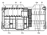
- FIG. 1 is a cross-sectional view seen from the side of a dishwasher in an embodiment of the present invention.
- FIG. 2 is a perspective view of the dishwasher of the dishwasher according to the embodiment of the present invention.
- FIG. 3 is a plan view of the dishwasher of the dishwasher according to the embodiment of the present invention.
- FIG. 4 is a plan view of a set basket of the dishwasher according to the embodiment of the present invention.
- FIG. 5 is a perspective view of a set basket of the dishwasher in the embodiment of the present invention.
- FIG. 6 is a perspective view of a set basket of the dishwasher according to the embodiment of the present invention.
- FIG. 7 is a perspective view of a main part of the set basket of the dishwasher according to the embodiment of the present invention.
- FIG. 1 is a cross-sectional view seen from the side of a dishwasher in an embodiment of the present invention.
- FIG. 2 is a perspective view of the dishwasher of the dishwasher according to the embodiment of the present invention.
- FIG. 3 is a plan view of the
- FIG. 8 is a cross-sectional view taken along 8-8 in FIG.
- FIG. 9A is a perspective view of the dishwasher of the dishwasher according to the embodiment of the present invention.
- FIG. 9B is a perspective view of a main part of the set basket of the dishwasher according to the embodiment of the present invention.
- FIG. 10 is a side sectional view of a conventional dishwasher.
- FIG. 11 is a perspective view of a tableware basket of a conventional dishwasher.
- FIG. 12 is a plan view of a tableware basket of a conventional dishwasher.
- FIG. 13 is a plan view of a set basket of a conventional dishwasher.
- FIG. 1 is a sectional view seen from the side of a dishwasher 100 according to an embodiment of the present invention.
- a dishwasher 100 shown in FIG. 1 is a desktop dishwasher installed on a kitchen counter or the like.
- the dishwasher 100 includes at least a housing 1, a washing tank 2, a water supply valve 3, a washing pump 5, a washing nozzle 7, a heater 8, and a dish basket. 23 and the drainage pump 11.
- a door body 1a into which tableware 9 is put in and out by opening and closing.
- the washing tub 2 is provided inside the dishwasher 100, and water or hot water is supplied to the washing tub 2 by the water supply valve 3.
- a drain hole 4 is provided at the bottom of the cleaning tank 2.
- the cleaning pump 5 is attached in communication with the drain hole 4 and is driven by a motor (not shown).
- the cleaning pump 5 sprays cleaning water from the cleaning nozzle 7 and circulates it inside the cleaning tank 2.
- a leftover filter 6 that collects leftovers washed away from the dishes 9 is provided in the drain hole 4.
- cleaning water the liquid used in the cleaning and rinsing steps of the objects to be cleaned such as the dishes 9 accommodated in the cleaning tank 2
- cleaning water the liquid used in the cleaning and rinsing steps of the objects to be cleaned such as the dishes 9 accommodated in the cleaning tank 2
- the cleaning water supplied and stored in the cleaning tank 2 passes through the leftover filter 6 and is sucked into the cleaning pump 5.
- the sucked cleaning water is pumped by a cleaning pump 5 to a cleaning nozzle 7 provided in the cleaning tank 2.
- the supplied washing water is sprayed from the washing nozzle 7 toward the dishes 9.
- the cleaning water sprayed from the cleaning nozzle 7 is circulated through a path that returns to the drain hole 4 after cleaning the dishes 9.
- the leftovers dropped from the dishes 9 flow into the leftover filter 6 together with the washing water.
- the remaining vegetables having a size that cannot pass through the remaining vegetable filter 6 are collected by the remaining vegetable filter 6.
- the heater 8 is disposed between the cleaning nozzle 7 and the bottom of the cleaning tank 2 and heats the cleaning water. Specifically, the heater 8 is energized almost simultaneously with the activation of the cleaning pump 5 when cleaning water is supplied to the cleaning tank 2 to a predetermined water level during cleaning. The cleaning water is heated to about 60 ° C. while circulating in the cleaning tank 2.
- the tableware basket 23 is configured so that the tableware 9 is arranged in an orderly manner, and is disposed above the cleaning nozzle 7. Thereby, in the dishwasher 100, with respect to the tableware 9 arrange
- a blower fan 13 for taking outside air into the washing tank 2 and a control device 15 for controlling and executing a series of washing operations are provided at the bottom of the main body of the dishwasher 100.
- a thermistor 14 that detects the temperature of the cleaning water is disposed outside the drain hole 4.
- the operation of the dishwasher 100 is controlled by the control device 15. First, a washing step of washing away food contaminants adhering to the tableware 9 is performed. In the washing step, the detergent put in advance in the washing tank 2 is dissolved, washing water containing the detergent is sprayed from the washing nozzle 7, and contaminants attached to the dishes 9 are washed away. Thereafter, the washing water in the washing tub 2 is replaced with clean washing water, and a rinsing step is performed for the detergent adhering to the dishes 9.
- a heating and rinsing step is performed with clean heated water heated at a high temperature of 70 ° C. to 80 ° C.
- a drying step follows the heating rinse step. In the drying step, outside air is taken into the cleaning tank 2 by the blower fan 13. And after the taken-in outside air is heated and heated with the heater 8, it is flowed between the tableware 9. FIG. Thereby, the water drop adhering to the tableware 9 is dried, and the tableware 9 is dried.
- FIG. 2 is a perspective view of the dish basket 23 of the dishwasher 100 in the present embodiment.
- FIG. 3 is a plan view of the dish basket 23 of the dishwasher 100 according to the present embodiment.
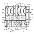
- FIG. 4 is a plan view of the set basket 25 of the dishwasher 100 in the present embodiment.
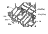
- 5 and 6 are perspective views of the set basket 25 of the dishwasher 100 in the present embodiment.
- FIG. 7 is a perspective view of a main part of the set basket 25 of the dishwasher 100 in the present embodiment.
- the tableware 9 illustrated in FIGS. 4 to 7 includes a bowl A, a middle dish B, a small dish C, a glass D, and a bowl E.
- the cups D include teacups and the like (not shown).
- the tableware 9 includes the platter F, the elongate cutlery G, such as a chopstick, a spoon, and a fork, the small articles J, such as a shed, and the kitchen knife K.
- the difference in the size distinguished in the small plate, the middle plate, the large plate, etc. means the difference in the relative size in the range which can be accommodated in the washing tank 2, and the size defined especially. There is no strict distinction between them.
- the tableware basket 23 is configured such that a frame body 24 made of wires and a frame body 24 are detachable, and a vertical beam 25a in a vertical direction and a horizontal beam 25b in a horizontal direction are combined. It consists of a set basket 25 integrally formed of resin and an accessory case 26 that can store cutlery upright.
- the direction indicated by the arrow X is the front where the door 1a is provided, and the dish basket 23 is pulled out from the washing tub 2 in the direction of the arrow X.
- the set basket 25 has a plurality of tableware set sections divided according to the type of tableware.
- a tableware set unit 27 on which the bowl A is placed for example, a tableware set unit 27 on which the bowl A is placed, a tableware set unit 28a on which the middle dish B is placed, and small tableware such as the cutlery G and the shed are placed.
- It has an accessory set portion 28b and a tableware set portion 29 that can be placed in either the small dishes C or the cups D.
- the bowl E has a similar shape to the bowl A and is placed on the tableware set unit 27. 2 and 3, a region where the set basket 25 and the accessory case 26 are not provided in the frame 24 is, for example, a tableware setting unit 24a on which a platter F or the like is placed.
- Bowls A, medium dishes B, small dishes C, bowls E and platters F are laid sideways, ie, bowls A, medium dishes B, small dishes C, bowls E and platters F
- the front surface and the back surface are placed upright so as to face the side wall of the cleaning tank 2.
- the cups D are placed with the drinking mouth facing downward.
- the tableware set unit 27 includes a plurality of support members 30 configured by two opposing horizontal bars 25b and ribs 31 formed in a plurality of rows so as to connect the plurality of support members 30.
- the support member 30 includes a support portion 30 a that supports two locations on the outer periphery that serve as a mouth portion of the pottery E that is placed sideways and a support pin that is erected on the support portion 30 a. 30b.
- One cage E is supported by two rows of support members 30 at a total of four points, two at each of the support points P1 and P2.
- the support pins 30b in the first row on the mouth side of the moss E support the lower part of the outer periphery that becomes the mouth of the moss E together with the support portion 30a from the front at the support points P1.
- the support pins 30b in the second row support the cage E from the rear at the support point P2.
- the central portion 31 a of the rib 31 has a convex shape imitating the contour shape of the outer periphery of the moss E, for example.
- the induction which imitated cross-sectional shape in the state where the moss E stood sideways, ie, the pot A or the moss E stood and placed so that the surface and the back of the mortar E faced the side wall of the cleaning tank 2 It has a shape.
- the user uses the guide shape of the rib 31, that is, the guide shape corresponding to the shape of the tableware 9 placed on the tableware set portion 27 (in FIG. 4, the tableware set portion 27 of the pottery A is placed.
- the tableware 9 placed on the tableware set portion 27 is a bowl A or a bowl E having a shape similar to the guide shape of the rib 31, and is placed It can be intuitively recognized that the direction to be performed is the direction indicated by the rib 31.
- small dishes C and cups D are placed in the tableware set unit 29. That is, in the tableware set unit 29, two tablewares having different shapes and placement methods are placed in one area.
- the tableware set unit 29 is composed of two facing horizontal bars 25 b different from the support member 30.
- the tableware set part 29 is formed on the support part 32 and supports the two parts on the outer periphery of the small dishes C placed sideways and placed on the support part 32, and supports the small dishes C from the rear.
- the pin 32a and the support pin 32b supported from the front shorter than the support pin 32a are comprised.
- the ribs 33 constituted by the vertical bars 25a connect the support portions 32 in a ladder shape. As shown in FIG.
- the rib 33 is formed in an arc shape in which the lower center portion swells downward, and when viewed from the side, a guide shape simulating the contour shape of the outer periphery of the placed small dish C It has become.
- the user simulates the guide shape of the rib 33, that is, the guide shape corresponding to the shape of the small dishes C placed on the tableware set portion 29 (in FIG. 4, the contour shape of the outer periphery of the small dishes C is imitated).
- the tableware 9 placed on the tableware set portion 29 by the guide shape is a small dish C having a shape similar to the guide shape of the rib 33, and the direction to be placed is also the direction indicated by the rib 33. Can be recognized intuitively.
- the tableware set portion 29 includes a support pin 34 and a ring-shaped rib 35 that are erected in addition to the support portion 32 and the rib 33.
- the rib 33 is provided to be inclined toward one of the support portions 32 to be connected.
- the cups D are placed so as to cover the support pins 34, the cups D are slightly tilted by the inclination of the ribs 33 and are supported on the support pins 34 from the inside and stably placed.
- the rib 33 serves as a support portion for the cups D, and serves as the guiding shape of the small dishes C described above. Further, as shown in FIG.
- the support pins 34 and the ring-shaped ribs 35 are formed every other one including the intermediate rib 33 a between the two ribs 33, and are clearly shown as the placement positions of the cups D.
- the ring-shaped rib 35 has a guide shape simulating the contour shape of the opening of the cup D to be placed or the cross-sectional shape of the trunk.
- the user uses the guide shape of the ring-shaped rib 35, that is, the guide shape corresponding to the shape of the cups D placed on the tableware set unit 29 (in FIG.
- the tableware 9 placed on the tableware set portion 29 is a cup D having a shape similar to the guide shape of the ring-shaped rib 35 by the shape simulating the cross-sectional shape of the placed state). It can be intuitively recognized that the position to be also the position indicated by the ring-shaped rib 35.
- the tableware set part 28a of the middle dish B includes a support pin 37 that supports the outer periphery of the middle dish B from below and a support pin that supports from the front. 38.
- the rib 39 connecting the support pins 37 is formed in an arc shape whose central portion swells downward, and the rib 39 has a guiding shape simulating the contour shape of the intermediate dish B to be placed.
- the user uses the guide shape of the rib 39, that is, the guide shape corresponding to the shape of the middle dish B placed on the tableware set portion 28a (in FIG.
- the tableware 9 placed on the tableware set portion 29 is a middle dish B having a shape similar to the guide shape of the rib 39 and should be placed. It can be intuitively recognized that the orientation is the orientation indicated by the rib 39.
- the accessory set portion 28b is formed in a lattice shape by the vertical beam 25a and the horizontal beam 25b.
- the vertical rail 25a has a central portion that curves downward and is lowered.
- the accessory set portion 28b is disposed between the row of the tableware set portion 27 on which the bowl A is placed and the row of the tableware set portion 29 on which the cup D is placed, and these tableware set portions. It is placed at a slightly lower position. With such a configuration, water droplets attached to the vertical rail 25a and the horizontal rail 25b are easily guided downward, the draining performance of the dish basket 23 can be improved, and the drying performance of the dishwasher 100 can be improved.
- the position where the accessory set portion 28b is provided becomes an empty space when the dishes are placed on the tableware set portion 27 or the tableware set portion 29.
- the set cage 25 of the present embodiment is provided with an accessory setting portion 28b by effectively using this empty space.
- FIG. 9A is a perspective view of the dish basket 23 of the dishwasher 100 in the present embodiment, and shows a state where the knife K is placed.
- FIG. 9B is a perspective view of a main part of the set car 25. As shown in FIG. 9B, in the tableware setting unit 29, the ribs 33 that support the cups D and the vertical bars 25a that constitute the intermediate ribs 33a are arranged side by side. And the fine groove
- the knife K is stably placed in the groove 25c so that the blade of the knife K does not slide, and is supported by the knife support portion 25d and the accessory case 26 so as not to fall down.
- the tableware set unit 29 has a kitchen knife set unit, and the kitchen knife K is safely held at a conspicuous position at the front of the tableware basket 23 in the drawer direction X of the tableware basket 23.
- the user confirms the placement position when the tableware 9 is placed on the tableware basket 23.
- the shape of each tableware is imitated in each position where the bowl A, the small dish C, the cup D, and the middle dish B are placed. Since the ribs 31, 33, 35, and 39 configured in a guide shape corresponding to the shape of the tableware are provided, the user can intuitively recognize the placement position and the placement direction. Thereby, the mounting time of the tableware 9 can be shortened.
- the dishwasher 100 since the washing water injection direction is set with respect to the tableware 9 correctly placed in the placement position, the dishwasher 100 has the washing water when the tableware 9 is placed in the wrong direction. However, there was a possibility that the cleaning performance was deteriorated. However, according to the present embodiment, since the user can intuitively recognize the placement position and the placement direction, the correctly placed tableware 9 is cleaned cleanly without making a mistake in the placement direction. Thereby, the dishwasher 100 which improved the cleaning efficiency can be provided.
- the cutlery G is normally stood and accommodated in the accessory case 26, but the cutlery G can be placed sideways in the accessory set portion 28b, and more cutlery G can be put together with the accessory case 26. Can be accommodated.
- small items J such as a spout and a demitasse cup can be stably stored without using the tableware set unit 29 of the cups D, and can store a large number of various types of tableware.
- the accessory setting unit 28b can effectively use space to place a large number of small tableware in particular, and the storage capacity of the tableware basket 23 is improved. 100 can be provided.
- the accessory set portion 28b is formed along the horizontal beam 25b, but may be formed along the vertical beam 25a.
- the accessory set portion 28b is formed so that the central portion of the vertical beam 25a is lower than the end portion, but may be formed so as to be inclined so that one end of the vertical beam 25a is lower. Also, the horizontal rail 25b may be formed to be inclined so that one end is lowered. Further, the accessory set portion 28b is not limited to resin, and may be formed of a wire or metal.
- the induction shape of the rib provided in the set basket 25 is not limited to the induction shape imitating the shapes of the bowls A, the middle dishes B, the small dishes C, and the cups D;
- Other tableware that can be placed and a shape imitating the shape of a cooking utensil such as a pan, or a shape corresponding to a state in which these tableware and cooking utensil are placed in the set basket 25 (for example, shown in FIG. 4)
- Such a cross-sectional shape in a state of being placed on the tableware set part 27 of the bowl A may be used.
- the set cage 25 of the present embodiment may have all of the ribs 31, 33, 35 and 39, or may have at least one of them. Moreover, you may have the rib comprised by the induction
- the dishwasher 100 is provided with the casing 1, the cleaning tank 2 provided in the casing 1, the cleaning tank 2, and the tableware 9 placed thereon.
- the tableware basket 23 is provided.
- the tableware basket 23 has a plurality of tableware set portions in which the pots A and dishes are set up side by side and placed side by side, and the plurality of tableware set portions are arranged in a row in the tableware basket.
- an accessory set portion 28b that can effectively use the space between a plurality of tableware set portions such as the bowl E or the dishes of the tableware basket 23 to place small tableware 9 and cutlery.
- An easy-to-use dishwasher 100 including the tableware basket 23 with improved capacity can be obtained.
- the accessory set portion 28b is formed in a lattice shape by the vertical beam 25a and the horizontal beam 25b. At least one of the vertical beam 25a and the horizontal beam 25b in the accessory set part 28b is formed so as to be inclined so that one end connected to one of the tableware set parts arranged next to the accessory set part 28b is lower than the other end. May be. In addition, at least one of the vertical beam 25a and the horizontal beam 25b in the accessory setting unit 28b may be formed such that the central portion is lower than both end portions. With such a configuration, water droplets attached to the vertical rail 25a and the horizontal rail 25b can be easily guided downward, improving the drainage of the tableware basket 23, and improving the drying performance of the dishwasher.
- the dishwasher 100 of embodiment of this invention is the ribs 31 and 33 comprised by the induction
- the user can intuitively recognize the placement position and placement direction of the tableware, and thus can place the tableware correctly and stably without making a mistake in the placement direction of the tableware.
- the tableware 9 placed correctly and stably is cleaned cleanly, the cleaning efficiency can be improved. Further, it is possible to reduce the trouble of trial and error as to which tableware should be placed where and how each time the tableware is placed, and the time for placing the tableware can be shortened.
- the present invention provides a small tableware set unit on which small tableware is placed between rows of a plurality of tableware set units in a dishwasher, and can improve the capacity of a tableware basket. . Therefore, the present invention is useful for a dishwasher and a dishwasher that efficiently install various types of tableware in a limited space.
Abstract
This invention is provided with a casing, a cleaning tank provided in the casing, and a tableware rack on which tableware is placed, the tableware rack having a plurality of rows of tableware positioning parts (27, 29) on which bowls and plates are placed, and a small tableware positioning part (28b) on which small tableware such as sake cups and cutlery are placed, the small tableware positioning part (28b) being provided between the rows of the tableware positioning parts (27, 29).
Description
本発明は食器類を洗浄する食器洗い機に関する。
The present invention relates to a dishwasher for washing dishes.
従来、一般的な食器洗い機は、洗浄ノズルより、加熱された洗浄水が食器類に向けて噴射されて食器類が洗浄される。
Conventionally, in a general dishwasher, heated washing water is sprayed from the washing nozzle toward the dishes to wash the dishes.
以下に、一般的な食器洗い機の構成について、図10を用いて説明する。図10は、従来の食器洗い機50の側方から見た断面図である。
Hereinafter, the configuration of a general dishwasher will be described with reference to FIG. FIG. 10 is a cross-sectional view of the conventional dishwasher 50 as viewed from the side.
図10に示すように、従来の食器洗い機50は、少なくとも、筐体51と、洗浄槽52と、給水弁53と、洗浄ポンプ55と、洗浄ノズル57と、ヒータ58と、食器かご60と、排水ポンプ61とから構成されている。食器洗い機50の本体の前面には、開閉により食器類59が出し入れされる扉体51aが設けられている。洗浄槽52は、食器洗い機50の内部に設けられ、給水弁53により洗浄槽52に水または湯が供給される。また、洗浄槽52の底部には、排水孔54が設けられている。洗浄ポンプ55は、排水孔54に連通して取り付けられ、モータ(図示せず)によって駆動される。洗浄ポンプ55は、洗浄槽52内の洗浄水を洗浄ノズル57から噴射させて洗浄槽52の内部に循環させる。また、食器類59から洗い落とされた残菜を捕集する残菜フィルタ56が、排水孔54に設けられている。
As shown in FIG. 10, the conventional dishwasher 50 includes at least a housing 51, a washing tank 52, a water supply valve 53, a washing pump 55, a washing nozzle 57, a heater 58, a dish basket 60, It consists of a drainage pump 61. On the front surface of the main body of the dishwasher 50, there is provided a door body 51a into which tableware 59 is put in and out by opening and closing. The washing tank 52 is provided inside the dishwasher 50, and water or hot water is supplied to the washing tank 52 by a water supply valve 53. A drain hole 54 is provided at the bottom of the cleaning tank 52. The cleaning pump 55 is attached in communication with the drain hole 54 and is driven by a motor (not shown). The cleaning pump 55 sprays the cleaning water in the cleaning tank 52 from the cleaning nozzle 57 and circulates it inside the cleaning tank 52. In addition, a leftover filter 56 that collects leftovers washed away from the tableware 59 is provided in the drain hole 54.
なお、以下、洗浄槽52内に収容された食器類59などの被洗浄物の洗浄およびすすぎステップで用いられる液体を、洗浄水と称して説明する。
In the following, the liquid used in the cleaning and rinsing steps of the objects to be cleaned such as tableware 59 accommodated in the cleaning tank 52 will be referred to as cleaning water.
まず、洗浄槽52内に供給され、貯留された洗浄水は、残菜フィルタ56を通過して洗浄ポンプ55に吸い込まれる。吸い込まれた洗浄水は、洗浄ポンプ55により洗浄槽52内に設けられた洗浄ノズル57に圧送される。供給された洗浄水は、洗浄ノズル57から食器類59に向けて噴射される。そして、洗浄ノズル57から噴射された洗浄水は、食器類59を洗浄した後、再び排水孔54に戻るという経路で循環される。このとき、食器類59から脱落した残菜などは、洗浄水とともに残菜フィルタ56に流入する。そして、残菜フィルタ56を通過できない大きさの残菜は残菜フィルタ56に捕集される。
First, the cleaning water supplied and stored in the cleaning tank 52 passes through the leftover filter 56 and is sucked into the cleaning pump 55. The sucked cleaning water is pumped by a cleaning pump 55 to a cleaning nozzle 57 provided in the cleaning tank 52. The supplied cleaning water is sprayed from the cleaning nozzle 57 toward the tableware 59. Then, the cleaning water sprayed from the cleaning nozzle 57 is circulated through a path that returns to the drain hole 54 after cleaning the dishes 59. At this time, the leftovers dropped from the tableware 59 flow into the leftover filter 56 together with the washing water. Then, the remaining vegetables having a size that cannot pass through the leftover filter 56 are collected by the leftover filter 56.
また、ヒータ58は、洗浄ノズル57と洗浄槽52の底部との間に配設され、洗浄水を加熱する。具体的には、ヒータ58は、洗浄時において、洗浄水が洗浄槽52に所定の水位まで給水されると、洗浄ポンプ55の起動とほぼ同時に通電される。そして、洗浄水は洗浄槽52内を循環しながら約60℃まで加熱される。また、食器かご60は、食器類59が整然と配置されるように構成され、洗浄ノズル57の上方に配設されている。これにより、食器洗い機50において、食器かご60に配置された食器類59に対して、洗浄水が効果的に食器類59に噴射されて洗浄が行われる。また、排水ポンプ61は、排水ホース62を通して洗浄水を機外に排出する。さらに、食器洗い機50の本体の底部に、外気を洗浄槽52に取り入れる送風ファン63と、一連の洗浄運転を制御して実行する制御装置65とが設けられている。また、洗浄水の温度を検知するサーミスタ64が排水孔54の外側に配設されている。
The heater 58 is disposed between the cleaning nozzle 57 and the bottom of the cleaning tank 52 and heats the cleaning water. Specifically, the heater 58 is energized almost simultaneously with the activation of the cleaning pump 55 when cleaning water is supplied to the cleaning tank 52 to a predetermined water level during cleaning. The cleaning water is heated to about 60 ° C. while circulating in the cleaning tank 52. The tableware basket 60 is configured such that the tableware 59 is arranged in an orderly manner, and is disposed above the cleaning nozzle 57. Thereby, in the dishwasher 50, with respect to the tableware 59 arrange | positioned at the tableware basket 60, a wash water is sprayed on the tableware 59 effectively, and washing is performed. Further, the drain pump 61 discharges the washing water through the drain hose 62 to the outside of the machine. Furthermore, a blower fan 63 for taking outside air into the washing tank 52 and a control device 65 for controlling and executing a series of washing operations are provided at the bottom of the main body of the dishwasher 50. A thermistor 64 that detects the temperature of the cleaning water is disposed outside the drain hole 54.
以上のように構成された食器洗い機50の運転について、以下に簡単に説明する。
The operation of the dishwasher 50 configured as described above will be briefly described below.
食器洗い機50の運転は、制御装置65により制御される。まず、食器類59に付着した食品の汚染物を洗い落とす洗浄ステップが行われる。洗浄ステップでは、洗浄槽52内に事前に投入された洗剤が溶かされ、洗剤を含んだ洗浄水が洗浄ノズル57から噴射され、食器類59に付着した汚染物が洗い落される。その後、洗浄槽52内の洗浄水がきれいな洗浄水に入れ替えられて、食器類59に付着した洗剤などをすすぐすすぎステップが行われる。
The operation of the dishwasher 50 is controlled by the control device 65. First, a washing step for washing away food contaminants attached to the tableware 59 is performed. In the washing step, the detergent put in advance in the washing tank 52 is dissolved, washing water containing the detergent is sprayed from the washing nozzle 57, and contaminants adhering to the tableware 59 are washed away. Thereafter, the washing water in the washing tank 52 is replaced with clean washing water, and a rinsing step is performed for the detergent attached to the tableware 59 and the like.
次に、さらに衛生的に仕上げるために、70℃~80℃の高温の加熱されたきれいな洗浄水ですすぐ加熱すすぎステップが行われる。加熱すすぎステップの次に乾燥ステップが行われる。乾燥ステップでは、外気が送風ファン63により洗浄槽52内に取り入れられる。そして、取り入れられた外気がヒータ58により加熱して暖められた後、食器類59の間に流される。これにより、食器類59に付着した水滴が乾かされ、食器類59が乾燥される。
Next, for a more sanitary finish, a heating and rinsing step is performed with clean heated water heated at a high temperature of 70 ° C. to 80 ° C. A drying step follows the heating rinse step. In the drying step, outside air is taken into the cleaning tank 52 by the blower fan 63. Then, after the outside air taken in is heated and heated by the heater 58, it flows between the dishes 59. Thereby, the water drop adhering to the tableware 59 is dried, and the tableware 59 is dried.
このような従来の食器洗い機50において、ワイヤ製の食器かごに樹脂製の食器かごを組み合わせ、着脱可能とするとともに、さまざまな形状の食器をセットできるようにしたものが提案されている(例えば、特許文献1参照)。図11は、従来の食器洗い機の食器かご60の斜視図である。図12は、従来の食器洗い機50の食器かご60の平面図である。図13は、従来の食器洗い機50の樹脂性のセットかご67の平面図である。
In such a conventional dishwasher 50, a combination of a tableware basket made of resin and a tableware basket made of resin so that it can be attached and detached and various types of tableware can be set has been proposed (for example, Patent Document 1). FIG. 11 is a perspective view of a dish basket 60 of a conventional dishwasher. FIG. 12 is a plan view of a dish basket 60 of a conventional dishwasher 50. FIG. 13 is a plan view of a resin set basket 67 of the conventional dishwasher 50.
食器かご60は、ワイヤ製の縦桟および横桟により格子状の枠体60aとして構成されている。そして、食器かご60の一部の領域には、皿類が戴置される皿類セット部66が形成されている。皿類セット部66には、ワイヤを上部に突出させて皿類の表面および裏面の一部を支持する支持ピン66aが形成されている。皿類セット部66においては、皿類が横向きに立てられて、すなわち、皿類の表面および裏面が洗浄槽52の側壁と相対するように立てられて、皿類の表面および裏面の一部が支持ピン66aに支持されて戴置される。
The tableware basket 60 is configured as a grid-like frame body 60a by vertical bars and horizontal bars made of wire. A dish set unit 66 on which dishes are placed is formed in a partial area of the tableware basket 60. The dish set portion 66 is formed with support pins 66a that project the wire upward and support a part of the front and back surfaces of the dish. In the dish setting unit 66, the dishes are set up sideways, that is, the dishes are set up so that the front and back surfaces of the dishes are opposed to the side walls of the cleaning tank 52, and a part of the front and back surfaces of the dishes are placed. The support pin 66a is supported and placed.
さらに、食器かご60には、格子状の枠体60aの縦桟または横桟に沿って、複数の食器セット部67aが列をなして配置されている。各食器セット部67aには、碗類などを戴置するための樹脂製のセットかご67が着脱可能に取り付けられている。また、セットかご67は、格子状の枠体60aのフラットな底面の上に戴置されている。
Furthermore, in the tableware basket 60, a plurality of tableware set portions 67a are arranged in a row along the vertical or horizontal rail of the lattice-like frame 60a. Each tableware set portion 67a is detachably attached with a resin set cage 67 for placing moss and the like. The set cage 67 is placed on the flat bottom surface of the lattice-shaped frame body 60a.
複数の食器セット部67aの列の間67bは、洗浄ノズル57により噴射された洗浄水を食器類59に効率よく当てるため、図12に示すように、なるべく大きい隙間を有する構成となっている。
In order to efficiently apply the cleaning water sprayed by the cleaning nozzle 57 to the tableware 59, the space 67b between the rows of the plurality of tableware setting sections 67a has a structure having a gap as large as possible as shown in FIG.
また、セットかご67には、図13に示すように、複数の突起形状などからなる支持ピン68が配置されている。食器洗い機50において、食器を効率よく洗浄するために、どのセットかご67にどの食器をどのように戴置させるかは、食器洗い機50が使用される度、使用者により判断され、決定される。例えば、使用者がセットかご67に碗類を載置する場合、洗浄ノズル57から噴射される洗浄水が碗類に効率よく当たるように、複数の支持ピン68を利用して碗類が支持される位置を変えて戴置する。このように、セットかご67の支持ピン68を利用することにより、食器かご60にさまざまな形状の食器が載置される。
Further, as shown in FIG. 13, the set cage 67 is provided with support pins 68 having a plurality of projection shapes and the like. In the dishwasher 50, in order to wash dishes efficiently, which tableware is placed in which set basket 67 is determined and determined by the user every time the dishwasher 50 is used. For example, when the user places the moss on the set basket 67, the moss is supported by using a plurality of support pins 68 so that the cleaning water sprayed from the cleaning nozzle 57 efficiently contacts the moss. Change the position to be placed. In this way, by using the support pins 68 of the set basket 67, various types of tableware are placed on the tableware basket 60.
しかしながら、上記従来の構成では、図12に示す複数の食器セット部67aの列の間67bは、食器かご60の強度を保つ程度の大きな隙間を有する格子で形成され、食器が載置されるように構成されていない。また、複数の食器セット部67aに、各食器セット部67aの底面を構成する格子の隙間よりも小さい形状および寸法の小物食器が戴置された場合は、小物食器が格子の隙間を通り抜けてセットかご67の下方に落下したり、小物食器が支持ピン68に十分に支持されずにぐらついたりして、安定して載置されないという問題を有している。
However, in the above conventional configuration, the space 67b between the rows of the plurality of tableware set portions 67a shown in FIG. 12 is formed by a lattice having a large gap enough to maintain the strength of the tableware basket 60 so that the tableware is placed. Is not configured. In addition, when small tableware having a shape and size smaller than the lattice gap constituting the bottom surface of each tableware set portion 67a is placed on the plurality of tableware set portions 67a, the small tableware is set through the lattice gap. There is a problem that it falls below the car 67 or the small tableware is not sufficiently supported by the support pins 68 and is not supported stably.
また、上述のとおり、食器洗い機50において、食器類59を最も効率よく洗浄するために、どのセットかご67にどの食器をどのように戴置させるかは、使用者の判断に委ねられるため、食器の洗浄効率性にバラつきが生じる。食器類59の戴置の仕方によっては、食器類59が効率よく洗浄されず、食器類59に汚れが残ってしまう場合もある。
In addition, as described above, in the dishwasher 50, in order to wash the dishes 59 most efficiently, it is up to the user to decide which table and how to place in which set basket 67. Variations in cleaning efficiency occur. Depending on how the tableware 59 is placed, the tableware 59 may not be washed efficiently, and the tableware 59 may remain dirty.
さらに、使用者は、様々な形状の食器類59をどのセットかご67にどのように戴置させれば安定して戴置できるかを、試行錯誤しながら判断しなければならないため、食器類59の戴置に時間がかかるという問題がある。
Furthermore, since the user has to determine, through trial and error, how to place the tableware 59 having various shapes on which set basket 67 to stably place the tableware 59, the tableware 59 There is a problem that it takes time to be placed.
本発明は、上記従来の構成における課題に鑑みてなされたものであり、食器の戴置安定性および収容性を向上させ、食器の戴置時間を短縮できる食器かごを備える食器洗い機を提供する。
The present invention has been made in view of the problems in the above-described conventional configuration, and provides a dishwasher equipped with a tableware basket that can improve the placement stability and capacity of the tableware and can shorten the time for placing the tableware.
具体的には、本発明の食器洗い機は、筐体と、筐体内に設けられる洗浄槽と、洗浄槽内に設けられ、食器類が戴置される食器かごとを備え、食器かごは、鉢類および皿類などが横向き立てて並べられて、すなわち、鉢類および皿類の表面および裏面が洗浄槽の側壁と相対するように立てられて戴置される食器セット部を複数有する。複数の食器セット部は互いに列をなして食器かご内に配置され、複数の食器セット部の列の間に、小物食器類が載置される小物セット部を有するものである。このような構成により、食器の収容性を向上させた食器かごを備える、使い勝手のよい食器洗い機を得ることができる。
Specifically, the dishwasher of the present invention includes a housing, a washing tub provided in the housing, and a tableware basket provided in the washing tub, on which tableware is placed. There are a plurality of tableware set portions in which dishes and dishes are placed side by side, that is, placed and placed such that the front and back surfaces of the bowls and dishes are opposed to the side walls of the washing tank. The plurality of tableware set units are arranged in a tableware basket in a row and have a small item set unit on which small tableware is placed between the plurality of tableware set unit rows. With such a configuration, it is possible to obtain an easy-to-use dishwasher including a tableware basket with improved tableware storage capacity.
以下、本発明の実施の形態について、図面を参照しながら説明する。なお、この実施の形態によって本発明が限定されるものではない。
Hereinafter, embodiments of the present invention will be described with reference to the drawings. Note that the present invention is not limited to the embodiments.
以下に、本発明の実施の形態における食器洗い機100の構成について、図面を参照しながら説明する。
Hereinafter, the configuration of the dishwasher 100 according to the embodiment of the present invention will be described with reference to the drawings.
図1は、本発明の実施の形態における食器洗い機100の側方から見た断面図である。図1に示される食器洗い機100は、キッチンカウンタなどの上に設置される卓上型食器洗い機である。
FIG. 1 is a sectional view seen from the side of a dishwasher 100 according to an embodiment of the present invention. A dishwasher 100 shown in FIG. 1 is a desktop dishwasher installed on a kitchen counter or the like.
図1に示すように、本実施の形態における食器洗い機100は、少なくとも、筐体1と、洗浄槽2と、給水弁3と、洗浄ポンプ5と、洗浄ノズル7と、ヒータ8と、食器かご23と、排水ポンプ11とから構成されている。食器洗い機100の本体の前面には、開閉により食器類9が出し入れされる扉体1aが設けられている。洗浄槽2は、食器洗い機100の内部に設けられ、給水弁3により洗浄槽2に水または湯が供給される。また、洗浄槽2の底部には、排水孔4が設けられている。洗浄ポンプ5は、排水孔4に連通して取り付けられ、モータ(図示せず)によって駆動される。洗浄ポンプ5は、洗浄水を洗浄ノズル7から噴射させて洗浄槽2の内部に循環させる。また、食器類9から洗い落とされた残菜を捕集する残菜フィルタ6が、排水孔4に設けられている。
As shown in FIG. 1, the dishwasher 100 according to the present embodiment includes at least a housing 1, a washing tank 2, a water supply valve 3, a washing pump 5, a washing nozzle 7, a heater 8, and a dish basket. 23 and the drainage pump 11. On the front surface of the main body of the dishwasher 100, there is provided a door body 1a into which tableware 9 is put in and out by opening and closing. The washing tub 2 is provided inside the dishwasher 100, and water or hot water is supplied to the washing tub 2 by the water supply valve 3. A drain hole 4 is provided at the bottom of the cleaning tank 2. The cleaning pump 5 is attached in communication with the drain hole 4 and is driven by a motor (not shown). The cleaning pump 5 sprays cleaning water from the cleaning nozzle 7 and circulates it inside the cleaning tank 2. In addition, a leftover filter 6 that collects leftovers washed away from the dishes 9 is provided in the drain hole 4.
なお、以下、洗浄槽2内に収容された食器類9などの被洗浄物の洗浄およびすすぎステップで用いられる液体を、洗浄水と称して説明する。
In the following, the liquid used in the cleaning and rinsing steps of the objects to be cleaned such as the dishes 9 accommodated in the cleaning tank 2 will be referred to as cleaning water.
まず、洗浄槽2内に供給され、貯留された洗浄水は、残菜フィルタ6を通過して洗浄ポンプ5に吸い込まれる。吸い込まれた洗浄水は、洗浄ポンプ5により洗浄槽2内に設けられた洗浄ノズル7に圧送される。供給された洗浄水は、洗浄ノズル7から食器類9に向けて噴射される。そして、洗浄ノズル7から噴射された洗浄水は、食器類9を洗浄した後、再び排水孔4に戻るという経路で循環される。このとき、食器類9から脱落した残菜などは、洗浄水とともに残菜フィルタ6に流入する。そして、残菜フィルタ6を通過できない大きさの残菜は残菜フィルタ6に捕集される。
First, the cleaning water supplied and stored in the cleaning tank 2 passes through the leftover filter 6 and is sucked into the cleaning pump 5. The sucked cleaning water is pumped by a cleaning pump 5 to a cleaning nozzle 7 provided in the cleaning tank 2. The supplied washing water is sprayed from the washing nozzle 7 toward the dishes 9. Then, the cleaning water sprayed from the cleaning nozzle 7 is circulated through a path that returns to the drain hole 4 after cleaning the dishes 9. At this time, the leftovers dropped from the dishes 9 flow into the leftover filter 6 together with the washing water. Then, the remaining vegetables having a size that cannot pass through the remaining vegetable filter 6 are collected by the remaining vegetable filter 6.
また、ヒータ8は、洗浄ノズル7と洗浄槽2の底部との間に配設され、洗浄水を加熱する。具体的には、ヒータ8は、洗浄時において、洗浄水が洗浄槽2に所定の水位まで給水されると、洗浄ポンプ5の起動とほぼ同時に通電される。そして、洗浄水は洗浄槽2内を循環しながら約60℃まで加熱される。また、食器かご23は、食器類9が整然と配置されるように構成され、洗浄ノズル7の上方に配設されている。これにより、食器洗い機100において、食器かご23に配置された食器類9に対して、洗浄水が効果的に食器類9に噴射されて効率的に洗浄が行われる。また、排水ポンプ11は、排水ホース12を通して洗浄水を機外に排出する。さらに、食器洗い機100の本体の底部に、外気を洗浄槽2に取り入れる送風ファン13と、一連の洗浄運転を制御して実行する制御装置15とが設けられている。また、洗浄水の温度を検知するサーミスタ14が排水孔4の外側に配設されている。
Also, the heater 8 is disposed between the cleaning nozzle 7 and the bottom of the cleaning tank 2 and heats the cleaning water. Specifically, the heater 8 is energized almost simultaneously with the activation of the cleaning pump 5 when cleaning water is supplied to the cleaning tank 2 to a predetermined water level during cleaning. The cleaning water is heated to about 60 ° C. while circulating in the cleaning tank 2. The tableware basket 23 is configured so that the tableware 9 is arranged in an orderly manner, and is disposed above the cleaning nozzle 7. Thereby, in the dishwasher 100, with respect to the tableware 9 arrange | positioned at the tableware basket 23, wash water is effectively sprayed on the tableware 9, and washing | cleaning is performed efficiently. Further, the drain pump 11 discharges the washing water through the drain hose 12 to the outside of the machine. Further, a blower fan 13 for taking outside air into the washing tank 2 and a control device 15 for controlling and executing a series of washing operations are provided at the bottom of the main body of the dishwasher 100. A thermistor 14 that detects the temperature of the cleaning water is disposed outside the drain hole 4.
以上のように構成された食器洗い機100の運転について、簡単に説明する。
The operation of the dishwasher 100 configured as described above will be briefly described.
食器洗い機100の運転は制御装置15により制御される。まず、食器類9に付着した食品の汚染物を洗い落とす洗浄ステップが行われる。洗浄ステップでは、洗浄槽2内に事前に投入された洗剤が溶かされ、洗剤を含んだ洗浄水が洗浄ノズル7から噴射され、食器類9に付着した汚染物が洗い落される。その後、洗浄槽2内の洗浄水がきれいな洗浄水に入れ替えられて、食器類9に付着した洗剤などをすすぐすすぎステップが行われる。
The operation of the dishwasher 100 is controlled by the control device 15. First, a washing step of washing away food contaminants adhering to the tableware 9 is performed. In the washing step, the detergent put in advance in the washing tank 2 is dissolved, washing water containing the detergent is sprayed from the washing nozzle 7, and contaminants attached to the dishes 9 are washed away. Thereafter, the washing water in the washing tub 2 is replaced with clean washing water, and a rinsing step is performed for the detergent adhering to the dishes 9.
次に、さらに衛生的に仕上げるために、70℃~80℃の高温の加熱されたきれいな洗浄水ですすぐ加熱すすぎステップが行われる。加熱すすぎステップの次に乾燥ステップが行われる。乾燥ステップでは、外気が送風ファン13により洗浄槽2内に取り入れられる。そして、取り入れられた外気がヒータ8により加熱して暖められた後、食器類9の間に流される。これにより、食器類9に付着した水滴が乾かされ、食器類9が乾燥される。
Next, for a more sanitary finish, a heating and rinsing step is performed with clean heated water heated at a high temperature of 70 ° C. to 80 ° C. A drying step follows the heating rinse step. In the drying step, outside air is taken into the cleaning tank 2 by the blower fan 13. And after the taken-in outside air is heated and heated with the heater 8, it is flowed between the tableware 9. FIG. Thereby, the water drop adhering to the tableware 9 is dried, and the tableware 9 is dried.
次に、本実施の形態における食器洗い機100に備えられた食器かご23について詳細に説明する。
Next, the tableware basket 23 provided in the dishwasher 100 according to the present embodiment will be described in detail.
図2は、本実施の形態における食器洗い機100の食器かご23の斜視図である。図3は、本実施の形態における食器洗い機100の食器かご23の平面図である。図4は、本実施の形態における食器洗い機100のセットかご25の平面図である。図5および図6は、本実施の形態における食器洗い機100のセットかご25の斜視図である。図7は、本実施の形態における食器洗い機100のセットかご25の要部斜視図である。なお、図4から図7に例示されている食器類9には、鉢類A、中皿類B、小皿類C、コップ類Dおよび碗類Eが含まれる。コップ類Dには図示しない湯飲み茶碗なども含まれる。また、図示しないが、食器類9には、大皿類F、箸、スプーンおよびフォークなどの細長いカトラリー類G、猪口などの小物類J、および包丁Kなども含まれる。なお、皿について、小皿、中皿および大皿などに区別された大きさの違いは、洗浄槽2に収容できる範囲での相対的な大きさの違いを意味するものであり、特に定義された大きさにより厳密に区別されるものではない。
FIG. 2 is a perspective view of the dish basket 23 of the dishwasher 100 in the present embodiment. FIG. 3 is a plan view of the dish basket 23 of the dishwasher 100 according to the present embodiment. FIG. 4 is a plan view of the set basket 25 of the dishwasher 100 in the present embodiment. 5 and 6 are perspective views of the set basket 25 of the dishwasher 100 in the present embodiment. FIG. 7 is a perspective view of a main part of the set basket 25 of the dishwasher 100 in the present embodiment. The tableware 9 illustrated in FIGS. 4 to 7 includes a bowl A, a middle dish B, a small dish C, a glass D, and a bowl E. The cups D include teacups and the like (not shown). Moreover, although not shown in figure, the tableware 9 includes the platter F, the elongate cutlery G, such as a chopstick, a spoon, and a fork, the small articles J, such as a shed, and the kitchen knife K. In addition, about the dish, the difference in the size distinguished in the small plate, the middle plate, the large plate, etc. means the difference in the relative size in the range which can be accommodated in the washing tank 2, and the size defined especially. There is no strict distinction between them.
図2および図3において、食器かご23は、ワイヤで構成された枠体24と、枠体24に着脱可能に構成され、縦方向の縦桟25aおよび横方向の横桟25bなどが組み合わされて樹脂で一体に形成されたセットかご25と、カトラリー類を立てて収容できる小物入れ26とで構成される。食器洗い機100においては、矢印Xに示される方向が扉体1aが設けられた前方であり、食器かご23は洗浄槽2から矢印X方向に引き出される。
In FIG. 2 and FIG. 3, the tableware basket 23 is configured such that a frame body 24 made of wires and a frame body 24 are detachable, and a vertical beam 25a in a vertical direction and a horizontal beam 25b in a horizontal direction are combined. It consists of a set basket 25 integrally formed of resin and an accessory case 26 that can store cutlery upright. In the dishwasher 100, the direction indicated by the arrow X is the front where the door 1a is provided, and the dish basket 23 is pulled out from the washing tub 2 in the direction of the arrow X.
図4から図7において、セットかご25は、食器の種類によって区分された複数の食器セット部を有する。セットかご25は、例えば、鉢類Aが戴置される食器セット部27と、中皿類Bが戴置される食器セット部28aと、カトラリー類Gおよび猪口などの小物食器が戴置される小物セット部28bと、小皿類Cおよびコップ類Dのいずれでも戴置できる食器セット部29とを有している。碗類Eは鉢類Aと類似形状であり、食器セット部27に戴置される。また、図2および図3において、枠体24においてセットかご25および小物入れ26が設けられていない領域は、例えば、大皿類Fなどが戴置される食器セット部24aである。鉢類A、中皿類B、小皿類C、碗類Eおよび大皿類Fは横向きに立てられて、すなわち、鉢類A、中皿類B、小皿類C、碗類Eおよび大皿類Fの表面および裏面が洗浄槽2の側壁と相対するように立てられて載置される。コップ類Dは、飲み口を下に向けて載置される。
4 to 7, the set basket 25 has a plurality of tableware set sections divided according to the type of tableware. In the set basket 25, for example, a tableware set unit 27 on which the bowl A is placed, a tableware set unit 28a on which the middle dish B is placed, and small tableware such as the cutlery G and the shed are placed. It has an accessory set portion 28b and a tableware set portion 29 that can be placed in either the small dishes C or the cups D. The bowl E has a similar shape to the bowl A and is placed on the tableware set unit 27. 2 and 3, a region where the set basket 25 and the accessory case 26 are not provided in the frame 24 is, for example, a tableware setting unit 24a on which a platter F or the like is placed. Bowls A, medium dishes B, small dishes C, bowls E and platters F are laid sideways, ie, bowls A, medium dishes B, small dishes C, bowls E and platters F The front surface and the back surface are placed upright so as to face the side wall of the cleaning tank 2. The cups D are placed with the drinking mouth facing downward.
まず、図4および図7を参照しながら、食器セット部27に鉢類Aまたは碗類Eが戴置される状態を説明する。
First, referring to FIGS. 4 and 7, a state where the bowl A or the bowl E is placed on the tableware set unit 27 will be described.
食器セット部27は、対向する2本の横桟25bで構成される複数の支持部材30と、これら複数の支持部材30を連結するように複数列形成されるリブ31とで構成される。図7において、支持部材30は、横向きに立てられて載置される碗類Eの口部となる外周の2ヶ所を下から支持する支持部30aと、支持部30aに立設された支持ピン30bとから構成される。1つの碗類Eは、2列の支持部材30により、支持点P1およびP2それぞれ2ヶ所の合計4点で支持される。碗類Eの口部側となる1列目の支持ピン30bは、支持部30aとともに碗類Eの口部となる外周の下側の2ヶ所をそれぞれ支持点P1で前方から支持する。2列目の支持ピン30bは、支持点P2で碗類Eを後方から支持する。
The tableware set unit 27 includes a plurality of support members 30 configured by two opposing horizontal bars 25b and ribs 31 formed in a plurality of rows so as to connect the plurality of support members 30. In FIG. 7, the support member 30 includes a support portion 30 a that supports two locations on the outer periphery that serve as a mouth portion of the pottery E that is placed sideways and a support pin that is erected on the support portion 30 a. 30b. One cage E is supported by two rows of support members 30 at a total of four points, two at each of the support points P1 and P2. The support pins 30b in the first row on the mouth side of the moss E support the lower part of the outer periphery that becomes the mouth of the moss E together with the support portion 30a from the front at the support points P1. The support pins 30b in the second row support the cage E from the rear at the support point P2.
リブ31の中央部31aは、図4に示すように、例えば碗類Eの外周の輪郭形状を模した凸形状となっており、リブ31は、上方から見ると、載置される鉢類Aまたは碗類Eが横向きに立てられて、すなわち、鉢類Aまたは碗類Eの表面および裏面が洗浄槽2の側壁と相対するように立てられて戴置された状態の断面形状を模した誘導形状となっている。使用者は、このリブ31の誘導形状により、すなわち、食器セット部27に戴置される食器類9の形状に対応する誘導形状(図4においては、鉢類Aの食器セット部27に戴置される状態の断面形状を模した凸形状)により、食器セット部27に戴置される食器類9が、リブ31の誘導形状と類似形状を有する鉢類Aまたは碗類Eであり、戴置すべき向きもリブ31で示される向きであることを直感的に認識できる。
As shown in FIG. 4, the central portion 31 a of the rib 31 has a convex shape imitating the contour shape of the outer periphery of the moss E, for example. Or the induction which imitated cross-sectional shape in the state where the moss E stood sideways, ie, the pot A or the moss E stood and placed so that the surface and the back of the mortar E faced the side wall of the cleaning tank 2 It has a shape. The user uses the guide shape of the rib 31, that is, the guide shape corresponding to the shape of the tableware 9 placed on the tableware set portion 27 (in FIG. 4, the tableware set portion 27 of the pottery A is placed. The tableware 9 placed on the tableware set portion 27 is a bowl A or a bowl E having a shape similar to the guide shape of the rib 31, and is placed It can be intuitively recognized that the direction to be performed is the direction indicated by the rib 31.
次に、図4から図6において、食器セット部29に小皿類Cおよびコップ類Dが戴置される。すなわち、食器セット部29には、形状も戴置方法も異なる2つの食器類が1つの領域に戴置される。
Next, in FIG. 4 to FIG. 6, small dishes C and cups D are placed in the tableware set unit 29. That is, in the tableware set unit 29, two tablewares having different shapes and placement methods are placed in one area.
まず、小皿類Cの戴置について説明する。食器セット部29は、支持部材30とは異なる対向する2本の横桟25bで構成される。食器セット部29は、横向きに立てられて載置される小皿類Cの外周の2ヶ所を下から支持する支持部32と、支持部32上に形成され、小皿類Cを後方から支持する支持ピン32aと、支持ピン32aより短く前方から支持する支持ピン32bとから構成される。縦桟25aで構成されるリブ33は、支持部32を梯子状に連結する。図5に示すように、リブ33は、下側中央部が下方に膨らむ円弧状に形成されており、側方から見ると、載置される小皿類Cの外周の輪郭形状を模した誘導形状となっている。使用者は、このリブ33の誘導形状により、すなわち、食器セット部29に戴置される小皿類Cの形状に対応する誘導形状(図4においては、小皿類Cの外周の輪郭形状を模した誘導形状)により、食器セット部29に戴置される食器類9が、リブ33の誘導形状と類似形状を有する小皿類Cであり、戴置すべき向きもリブ33で示される向きであることを直感的に認識できる。
First, the placement of small dishes C will be described. The tableware set unit 29 is composed of two facing horizontal bars 25 b different from the support member 30. The tableware set part 29 is formed on the support part 32 and supports the two parts on the outer periphery of the small dishes C placed sideways and placed on the support part 32, and supports the small dishes C from the rear. The pin 32a and the support pin 32b supported from the front shorter than the support pin 32a are comprised. The ribs 33 constituted by the vertical bars 25a connect the support portions 32 in a ladder shape. As shown in FIG. 5, the rib 33 is formed in an arc shape in which the lower center portion swells downward, and when viewed from the side, a guide shape simulating the contour shape of the outer periphery of the placed small dish C It has become. The user simulates the guide shape of the rib 33, that is, the guide shape corresponding to the shape of the small dishes C placed on the tableware set portion 29 (in FIG. 4, the contour shape of the outer periphery of the small dishes C is imitated). The tableware 9 placed on the tableware set portion 29 by the guide shape) is a small dish C having a shape similar to the guide shape of the rib 33, and the direction to be placed is also the direction indicated by the rib 33. Can be recognized intuitively.
つぎに、コップ類Dの戴置について説明する。食器セット部29は、支持部32およびリブ33に加え、立設された支持ピン34とリング状リブ35とで構成されている。リブ33は、連結する支持部32の一方に向かって傾斜して設けられている。コップ類Dは支持ピン34に被せるように伏せて戴置されると、リブ33の傾斜により少し傾いて支持ピン34に内側から支持されて安定して載置される。このとき、リブ33が、コップ類Dの支持部となり、上述した小皿類Cの誘導形状とを兼ねる構成となっている。また、支持ピン34およびリング状リブ35は、図4に示すように、2本のリブ33の間に中間リブ33aを含んで1つ置きに形成され、コップ類Dの戴置位置として明示される。このリング状リブ35は、上方から見ると、載置されるコップ類Dの開口部の輪郭形状または胴部の横断面形状を模した誘導形状となっている。使用者は、このリング状リブ35の誘導形状により、すなわち、食器セット部29に戴置されるコップ類Dの形状に対応する誘導形状(図4においては、コップ類Dの食器セット部29に戴置される状態の横断面形状を模した形状)により、食器セット部29に戴置される食器類9が、リング状リブ35の誘導形状と類似形状を有するコップ類Dであり、戴置すべき位置もリング状リブ35で示される位置であることを直感的に認識できる。
Next, the placement of the cups D will be described. The tableware set portion 29 includes a support pin 34 and a ring-shaped rib 35 that are erected in addition to the support portion 32 and the rib 33. The rib 33 is provided to be inclined toward one of the support portions 32 to be connected. When the cups D are placed so as to cover the support pins 34, the cups D are slightly tilted by the inclination of the ribs 33 and are supported on the support pins 34 from the inside and stably placed. At this time, the rib 33 serves as a support portion for the cups D, and serves as the guiding shape of the small dishes C described above. Further, as shown in FIG. 4, the support pins 34 and the ring-shaped ribs 35 are formed every other one including the intermediate rib 33 a between the two ribs 33, and are clearly shown as the placement positions of the cups D. The When viewed from above, the ring-shaped rib 35 has a guide shape simulating the contour shape of the opening of the cup D to be placed or the cross-sectional shape of the trunk. The user uses the guide shape of the ring-shaped rib 35, that is, the guide shape corresponding to the shape of the cups D placed on the tableware set unit 29 (in FIG. The tableware 9 placed on the tableware set portion 29 is a cup D having a shape similar to the guide shape of the ring-shaped rib 35 by the shape simulating the cross-sectional shape of the placed state). It can be intuitively recognized that the position to be also the position indicated by the ring-shaped rib 35.
また、図4から図6において、中皿類Bの食器セット部28aは、中皿類Bの外周を下から支持する支持部材36上に後方から支持する支持ピン37と前方から支持する支持ピン38とから構成される。支持ピン37を連結するリブ39は中央部が下方に膨らむ円弧状に形成され、リブ39は載置される中皿類Bの輪郭形状を模した誘導形状となっている。使用者は、このリブ39の誘導形状により、すなわち、食器セット部28aに戴置される中皿類Bの形状に対応する誘導形状(図4においては、中皿類Bの食器セット部28aに戴置される状態の断面形状を模した形状)により、食器セット部29に戴置される食器類9が、リブ39の誘導形状と類似形状を有する中皿類Bであり、戴置すべき向きもリブ39で示される向きであることを直感的に認識できる。
4 to 6, the tableware set part 28a of the middle dish B includes a support pin 37 that supports the outer periphery of the middle dish B from below and a support pin that supports from the front. 38. The rib 39 connecting the support pins 37 is formed in an arc shape whose central portion swells downward, and the rib 39 has a guiding shape simulating the contour shape of the intermediate dish B to be placed. The user uses the guide shape of the rib 39, that is, the guide shape corresponding to the shape of the middle dish B placed on the tableware set portion 28a (in FIG. The tableware 9 placed on the tableware set portion 29 is a middle dish B having a shape similar to the guide shape of the rib 39 and should be placed. It can be intuitively recognized that the orientation is the orientation indicated by the rib 39.
また、図4から図6において、小物セット部28bは、縦桟25aと横桟25bとによって格子状に形成される。また、図8において、縦桟25aは側方から見ると中央部が下方に湾曲して低くなっている。また、小物セット部28bは、鉢類Aが戴置される食器セット部27の列およびコップ類Dが戴置される食器セット部29の列の間に配置され、かつ、これらの食器セット部より少し低い位置に配置されている。このような構成により、縦桟25aおよび横桟25bに付着した水滴が下方に誘導されやすく、食器かご23の水切り性を向上して、食器洗い機100の乾燥性能を向上させることができる。
Further, in FIGS. 4 to 6, the accessory set portion 28b is formed in a lattice shape by the vertical beam 25a and the horizontal beam 25b. Further, in FIG. 8, when viewed from the side, the vertical rail 25a has a central portion that curves downward and is lowered. The accessory set portion 28b is disposed between the row of the tableware set portion 27 on which the bowl A is placed and the row of the tableware set portion 29 on which the cup D is placed, and these tableware set portions. It is placed at a slightly lower position. With such a configuration, water droplets attached to the vertical rail 25a and the horizontal rail 25b are easily guided downward, the draining performance of the dish basket 23 can be improved, and the drying performance of the dishwasher 100 can be improved.
また、セットかご25において、小物セット部28bが設けられている位置は、食器セット部27または食器セット部29に皿類が戴置されたときには、空間として空きスペースになる。本実施の形態のセットかご25には、この空いたスペースを有効に利用して小物セット部28bが設けられている。
Also, in the set basket 25, the position where the accessory set portion 28b is provided becomes an empty space when the dishes are placed on the tableware set portion 27 or the tableware set portion 29. The set cage 25 of the present embodiment is provided with an accessory setting portion 28b by effectively using this empty space.
さらに、図9Aは、本実施の形態における食器洗い機100の食器かご23の斜視図で、包丁Kが戴置された状態を示す。図9Bは、セットかご25の要部斜視図である。図9Bに示すように、食器セット部29では、コップ類Dを支持するリブ33および中間リブ33aを構成する縦桟25aが横並びに連続する。そして、これらの縦桟25aの所定位置に横方向の細かい溝25cが形成されている。包丁Kの先端が戴置される近傍には包丁支持部25dが形成されている。包丁Kは、包丁Kの刃が滑らないように溝25cに安定して戴置され、包丁支持部25dおよび小物入れ26により倒れないように支持される。このようにして、食器セット部29は包丁用食器セット部を有し、食器かご23の引き出し方向Xにおける食器かご23の前部となる目立つ位置で、包丁Kが安全に保持される。
Furthermore, FIG. 9A is a perspective view of the dish basket 23 of the dishwasher 100 in the present embodiment, and shows a state where the knife K is placed. FIG. 9B is a perspective view of a main part of the set car 25. As shown in FIG. 9B, in the tableware setting unit 29, the ribs 33 that support the cups D and the vertical bars 25a that constitute the intermediate ribs 33a are arranged side by side. And the fine groove | channel 25c of the horizontal direction is formed in the predetermined position of these vertical bars 25a. A knife support portion 25d is formed in the vicinity where the tip of the knife K is placed. The knife K is stably placed in the groove 25c so that the blade of the knife K does not slide, and is supported by the knife support portion 25d and the accessory case 26 so as not to fall down. In this way, the tableware set unit 29 has a kitchen knife set unit, and the kitchen knife K is safely held at a conspicuous position at the front of the tableware basket 23 in the drawer direction X of the tableware basket 23.
以上のように構成された食器洗い機100について、以下その動作および作用を説明する。
The operation and action of the dishwasher 100 configured as described above will be described below.
使用者は、食器類9が食器かご23に載置されるときに戴置位置を確認する。このとき、セットかご25には、鉢類A、小皿類C、コップ類Dおよび中皿類Bが戴置されるそれぞれの位置に、それぞれの食器の形状を模し、戴置されるそれぞれの食器の形状に対応する誘導形状で構成されたリブ31,33,35,39が設けられているため、使用者は直感的に戴置位置および戴置方向を認識することができる。これにより、食器類9の載置時間を短縮することができる。
The user confirms the placement position when the tableware 9 is placed on the tableware basket 23. At this time, in the set basket 25, the shape of each tableware is imitated in each position where the bowl A, the small dish C, the cup D, and the middle dish B are placed. Since the ribs 31, 33, 35, and 39 configured in a guide shape corresponding to the shape of the tableware are provided, the user can intuitively recognize the placement position and the placement direction. Thereby, the mounting time of the tableware 9 can be shortened.
また、食器洗い機100は、戴置位置に正しく戴置された食器類9に対して洗浄水の噴射方向が設定されているため、間違った方向に食器類9が載置された場合、洗浄水が勢いよく当たらず洗浄性能の低下を招くおそれがあった。しかし、本実施の形態によれば、使用者は直感的に戴置位置および戴置方向が認識できるため、戴置方向を間違えることなく、正しく戴置された食器類9はきれいに洗浄される。これにより、洗浄効率性を向上させた食器洗い機100を提供することができる。
Moreover, since the washing water injection direction is set with respect to the tableware 9 correctly placed in the placement position, the dishwasher 100 has the washing water when the tableware 9 is placed in the wrong direction. However, there was a possibility that the cleaning performance was deteriorated. However, according to the present embodiment, since the user can intuitively recognize the placement position and the placement direction, the correctly placed tableware 9 is cleaned cleanly without making a mistake in the placement direction. Thereby, the dishwasher 100 which improved the cleaning efficiency can be provided.
さらに、カトラリー類Gは、通常は小物入れ26に立てられて収容されるが、小物セット部28bにはカトラリー類Gを横向きに戴置でき、小物入れ26と合わせてより多くのカトラリー類Gを収容できる。また、猪口およびデミタスカップなどの小物類Jもコップ類Dの食器セット部29を使用せずとも安定して収容することができ、多様な形状の食器をより多く収容することができる。このように、小物セット部28bには、空間を有効に活用して、特に小さな形状の小物食器類を多く戴置させることでき、食器かご23の収容性が向上された、使い勝手のよい食器洗い機100を提供することができる。
Further, the cutlery G is normally stood and accommodated in the accessory case 26, but the cutlery G can be placed sideways in the accessory set portion 28b, and more cutlery G can be put together with the accessory case 26. Can be accommodated. In addition, small items J such as a spout and a demitasse cup can be stably stored without using the tableware set unit 29 of the cups D, and can store a large number of various types of tableware. In this way, the accessory setting unit 28b can effectively use space to place a large number of small tableware in particular, and the storage capacity of the tableware basket 23 is improved. 100 can be provided.
また、縦桟25aの中央側が下方に湾曲して低くなっていることにより、縦桟25aに付着した水滴が下方に誘導されやすく、食器かご23の水切り性が向上されて、食器洗い機の乾燥性能を向上させることができる。
In addition, since the central side of the vertical rail 25a is curved and lowered, water drops attached to the vertical rail 25a are easily guided downward, the draining performance of the dish basket 23 is improved, and the drying performance of the dishwasher Can be improved.
なお、本実施の形態では、小物セット部28bが横桟25bに沿って形成されているが、縦桟25aに沿って形成されていてもよい。
In the present embodiment, the accessory set portion 28b is formed along the horizontal beam 25b, but may be formed along the vertical beam 25a.
また、小物セット部28bは、縦桟25aの中央部が端部より低くなるように形成されているが、縦桟25aの一端が低くなるように傾斜させて形成されたものでもよい。また、横桟25bも、一端が低くなるように傾斜させて形成されたものでもよい。さらに、小物セット部28bは樹脂製に限らず、ワイヤまたは金属で形成されていてもよい。
The accessory set portion 28b is formed so that the central portion of the vertical beam 25a is lower than the end portion, but may be formed so as to be inclined so that one end of the vertical beam 25a is lower. Also, the horizontal rail 25b may be formed to be inclined so that one end is lowered. Further, the accessory set portion 28b is not limited to resin, and may be formed of a wire or metal.
また、セットかご25に設けられるリブの誘導形状は、鉢類A、中皿類B、小皿類Cおよびコップ類Dの形状を模した誘導形状に限定されるものではなく、食器かご23に戴置可能な他の食器、および、鍋等の調理器具の形状を模したもの、或いは、これら食器および調理器具などがセットかご25に戴置される状態に対応した形状(例えば、図4に示すような、鉢類Aの食器セット部27に戴置される状態の断面形状)を模したものでもよい。
The induction shape of the rib provided in the set basket 25 is not limited to the induction shape imitating the shapes of the bowls A, the middle dishes B, the small dishes C, and the cups D; Other tableware that can be placed and a shape imitating the shape of a cooking utensil such as a pan, or a shape corresponding to a state in which these tableware and cooking utensil are placed in the set basket 25 (for example, shown in FIG. 4) Such a cross-sectional shape in a state of being placed on the tableware set part 27 of the bowl A may be used.
また、本実施の形態のセットかご25は、リブ31,33,35および39の全てを有していてもよいし、これらのうち少なくとも一つを有しているものでもよい。また、上述のとおり、リブ31,33,35および39の誘導形状のいずれとも異なる誘導形状で構成されたリブを有していてもよい。
Further, the set cage 25 of the present embodiment may have all of the ribs 31, 33, 35 and 39, or may have at least one of them. Moreover, you may have the rib comprised by the induction | guidance | derivation shape different from all of the induction | guidance | derivation shapes of the ribs 31, 33, 35, and 39 as above-mentioned.
以上述べたように、本発明の実施の形態の食器洗い機100は、筐体1と、筐体1内に設けられる洗浄槽2と、洗浄槽2内に設けられ、食器類9が戴置される食器かご23とを備える。食器かご23は、鉢類Aおよび皿類などが立てられて横向きに並べられて戴置される食器セット部を複数有し、複数の食器セット部は、互いに列をなして食器かご内に配置され、複数の食器セット部の列の間に小物食器類を載置する小物セット部28bを有するものである。このような構成により、食器かご23の碗類Eまたは皿類などの複数の食器セット部の間を有効に活用し、小さな食器類9およびカトラリー類などを載置できる小物セット部28bを有し、収容性を向上させた食器かご23を備える、使い勝手のよい食器洗い機100を得ることができる。
As described above, the dishwasher 100 according to the embodiment of the present invention is provided with the casing 1, the cleaning tank 2 provided in the casing 1, the cleaning tank 2, and the tableware 9 placed thereon. The tableware basket 23 is provided. The tableware basket 23 has a plurality of tableware set portions in which the pots A and dishes are set up side by side and placed side by side, and the plurality of tableware set portions are arranged in a row in the tableware basket. In addition, there is an accessory set portion 28b for placing accessory tableware between rows of a plurality of tableware set portions. With such a configuration, there is an accessory set portion 28b that can effectively use the space between a plurality of tableware set portions such as the bowl E or the dishes of the tableware basket 23 to place small tableware 9 and cutlery. An easy-to-use dishwasher 100 including the tableware basket 23 with improved capacity can be obtained.
また、本発明の実施の形態の食器洗い機100は、小物セット部28bが、縦桟25aと横桟25bとにより格子状に形成されている。小物セット部28bにおける縦桟25aおよび横桟25bの少なくとも一方は、小物セット部28bの隣に配置される食器セット部のうちの一つと連結する一端が他端より低くなるように傾斜して形成されていてもよい。また、小物セット部28bにおける縦桟25aおよび横桟25bの少なくとも一方は、中央部が両端部より低くなるように形成されていてもよい。このような構成により、縦桟25aおよび横桟25bに付着した水滴が下方に誘導されやすく、食器かご23の水切り性を向上して、食器洗い機の乾燥性能を向上させることができる。
Further, in the dishwasher 100 according to the embodiment of the present invention, the accessory set portion 28b is formed in a lattice shape by the vertical beam 25a and the horizontal beam 25b. At least one of the vertical beam 25a and the horizontal beam 25b in the accessory set part 28b is formed so as to be inclined so that one end connected to one of the tableware set parts arranged next to the accessory set part 28b is lower than the other end. May be. In addition, at least one of the vertical beam 25a and the horizontal beam 25b in the accessory setting unit 28b may be formed such that the central portion is lower than both end portions. With such a configuration, water droplets attached to the vertical rail 25a and the horizontal rail 25b can be easily guided downward, improving the drainage of the tableware basket 23, and improving the drying performance of the dishwasher.
また、本発明の実施の形態の食器洗い機100は、食器かご23に、食器セット部27,28a,29に戴置される食器類9の形状に対応する誘導形状で構成されたリブ31,33,35,39を有するセットかごが設けられている。このような構成により、使用者は直感的に食器の戴置位置および戴置方向が認識できるため、食器の戴置方向を間違えることなく、正しく安定させて戴置することができる。また、正しく安定して戴置された食器類9はきれいに洗浄されるため、洗浄効率性を向上させることができる。さらに、食器を戴置させるたびにどの食器をどこにどのように戴置すればよいか試行錯誤する煩わしさを削減することができ、食器の戴置時間を短縮することができる。
Moreover, the dishwasher 100 of embodiment of this invention is the ribs 31 and 33 comprised by the induction | guidance | derivation shape corresponding to the shape of the tableware 9 placed in the tableware basket 23 by the tableware set part 27,28a, 29. , 35, 39 are provided. With such a configuration, the user can intuitively recognize the placement position and placement direction of the tableware, and thus can place the tableware correctly and stably without making a mistake in the placement direction of the tableware. In addition, since the tableware 9 placed correctly and stably is cleaned cleanly, the cleaning efficiency can be improved. Further, it is possible to reduce the trouble of trial and error as to which tableware should be placed where and how each time the tableware is placed, and the time for placing the tableware can be shortened.
以上のように、本発明は、食器洗い機における複数の食器セット部の列の間に、小物食器類が載置される小物食器セット部を提供し、食器かごの収容性を向上することができる。よって、本発明は、多種の食器類を限られた空間内に効率よく設置させる食器洗い機および食器洗い乾燥機などに有用である。
As described above, the present invention provides a small tableware set unit on which small tableware is placed between rows of a plurality of tableware set units in a dishwasher, and can improve the capacity of a tableware basket. . Therefore, the present invention is useful for a dishwasher and a dishwasher that efficiently install various types of tableware in a limited space.
1 筐体
1a 扉体
2 洗浄槽
3 給水弁
4 排水孔
5 洗浄ポンプ
6 残菜フィルタ
7 洗浄ノズル
8 ヒータ
9 食器類
11 排水ポンプ
12 排水ホース
13 送風ファン
14 サーミスタ
15 制御装置
23 食器かご
24 枠体
24a 食器セット部
25 セットかご
25a 縦桟
25b 横桟
25c 溝
26 小物入れ
27 食器セット部
28a 食器セット部
28b 小物セット部
29 食器セット部
30 支持部材
30a 支持部
30b 支持ピン
31 リブ
32 支持部
32a,32b 支持ピン
33 リブ
34 支持ピン
35 リング状リブ
36 支持部材
37 支持ピン
38 支持ピン
39 リブ
A 鉢類
B 中皿類
C 小皿類
D コップ類
E 碗類
F 大皿類
G カトラリー類
J 小物類
K 包丁 DESCRIPTION OF SYMBOLS 1Case 1a Door body 2 Washing tank 3 Water supply valve 4 Drainage hole 5 Washing pump 6 Vegetable filter 7 Washing nozzle 8 Heater 9 Tableware 11 Drainage pump 12 Drainage hose 13 Blower fan 14 Thermistor 15 Controller 23 Tableware basket 24 Frame body 24a Tableware set section 25 Set basket 25a Vertical rail 25b Horizontal rail 25c Groove 26 Small container 27 Tableware set section 28a Tableware set section 28b Small article set section 29 Tableware set section 30 Support member 30a Support section 30b Support pin 31 Rib 32 Support section 32a, 32b Support pin 33 Rib 34 Support pin 35 Ring-shaped rib 36 Support member 37 Support pin 38 Support pin 39 Rib A Bowl B Medium dish C Small dish D Cup E E Bowl F Large dish G Cutlery J Small goods K Knife
1a 扉体
2 洗浄槽
3 給水弁
4 排水孔
5 洗浄ポンプ
6 残菜フィルタ
7 洗浄ノズル
8 ヒータ
9 食器類
11 排水ポンプ
12 排水ホース
13 送風ファン
14 サーミスタ
15 制御装置
23 食器かご
24 枠体
24a 食器セット部
25 セットかご
25a 縦桟
25b 横桟
25c 溝
26 小物入れ
27 食器セット部
28a 食器セット部
28b 小物セット部
29 食器セット部
30 支持部材
30a 支持部
30b 支持ピン
31 リブ
32 支持部
32a,32b 支持ピン
33 リブ
34 支持ピン
35 リング状リブ
36 支持部材
37 支持ピン
38 支持ピン
39 リブ
A 鉢類
B 中皿類
C 小皿類
D コップ類
E 碗類
F 大皿類
G カトラリー類
J 小物類
K 包丁 DESCRIPTION OF SYMBOLS 1
Claims (3)
- 筐体と、前記筐体内に設けられた洗浄槽と、前記洗浄槽内に設けられ、食器類が戴置される食器かごとを備え、前記食器かごは、食器類が戴置される食器セット部を複数有し、前記複数の食器セット部は、互いに列をなして食器かご内に配置され、前記複数の食器セット部の前記列の間に小物食器類が載置される小物セット部が設けられた食器洗い機。 A table, a washing tub provided in the case, and a tableware basket provided in the cleaning tub, on which tableware is placed, wherein the tableware basket is a tableware set on which tableware is placed A plurality of tableware sets, the plurality of tableware set units arranged in rows in a tableware basket, and a small item set unit on which small tableware is placed between the columns of the plurality of tableware set units. Dishwasher provided.
- 前記小物セット部は、縦桟および横桟により格子状に形成され、前記縦桟および前記横桟の少なくとも一方は、一端が他端より低くなるように傾斜して形成された、または、中央部が両端より低くなるように形成された、請求項1記載の食器洗い機。 The accessory set part is formed in a lattice shape with vertical bars and horizontal bars, and at least one of the vertical bars and the horizontal bars is formed so as to be inclined so that one end is lower than the other end, or the center part. The dishwasher according to claim 1, wherein the dishwasher is formed to be lower than both ends.
- 前記食器かごに、戴置される食器の形状に対応する誘導形状で構成されたリブを有するセットかごが設けられた請求項1記載の食器洗い機。 The dishwasher according to claim 1, wherein the tableware basket is provided with a set basket having ribs configured in a guide shape corresponding to a shape of the tableware to be placed.
Priority Applications (1)
| Application Number | Priority Date | Filing Date | Title |
|---|---|---|---|
| CN201580009201.0A CN106028898A (en) | 2014-02-28 | 2015-01-13 | Dishwasher |
Applications Claiming Priority (2)
| Application Number | Priority Date | Filing Date | Title |
|---|---|---|---|
| JP2014-037866 | 2014-02-28 | ||
| JP2014037866A JP2015160028A (en) | 2014-02-28 | 2014-02-28 | dishwasher |
Publications (1)
| Publication Number | Publication Date |
|---|---|
| WO2015129146A1 true WO2015129146A1 (en) | 2015-09-03 |
Family
ID=54008485
Family Applications (1)
| Application Number | Title | Priority Date | Filing Date |
|---|---|---|---|
| PCT/JP2015/000108 WO2015129146A1 (en) | 2014-02-28 | 2015-01-13 | Dishwasher |
Country Status (3)
| Country | Link |
|---|---|
| JP (1) | JP2015160028A (en) |
| CN (1) | CN106028898A (en) |
| WO (1) | WO2015129146A1 (en) |
Cited By (1)
| Publication number | Priority date | Publication date | Assignee | Title |
|---|---|---|---|---|
| CN111789391A (en) * | 2020-08-06 | 2020-10-20 | 杨宏俪 | Shallow of dining room tableware is received to quick convenience |
Families Citing this family (1)
| Publication number | Priority date | Publication date | Assignee | Title |
|---|---|---|---|---|
| CN109998438B (en) * | 2019-04-15 | 2020-10-02 | 佛山市顺德区美的洗涤电器制造有限公司 | Dish washing machine, and use guiding device and method of dish washing machine |
Citations (9)
| Publication number | Priority date | Publication date | Assignee | Title |
|---|---|---|---|---|
| JPS6428258U (en) * | 1987-08-13 | 1989-02-20 | ||
| JPH01138366U (en) * | 1988-03-17 | 1989-09-21 | ||
| JPH0464355U (en) * | 1990-10-09 | 1992-06-02 | ||
| JPH1014854A (en) * | 1996-07-05 | 1998-01-20 | Nakanishi Seisakusho:Kk | Tableware cage for provision of school meals |
| JPH10234641A (en) * | 1997-03-03 | 1998-09-08 | Matsushita Electric Ind Co Ltd | Tableware washing machine |
| JPH11342103A (en) * | 1998-04-03 | 1999-12-14 | Toto Ltd | Dish washer |
| JP2002017643A (en) * | 2000-07-05 | 2002-01-22 | Matsushita Electric Ind Co Ltd | Dishwasher |
| JP2005124625A (en) * | 2003-10-21 | 2005-05-19 | Toshiba Corp | Dishwasher |
| US20120298598A1 (en) * | 2011-05-24 | 2012-11-29 | Miele & Cie. Kg | Dish rack, in particular upper rack |
Family Cites Families (5)
| Publication number | Priority date | Publication date | Assignee | Title |
|---|---|---|---|---|
| JP2003180607A (en) * | 2003-01-15 | 2003-07-02 | Matsushita Electric Ind Co Ltd | Dishwasher |
| JP2005334259A (en) * | 2004-05-26 | 2005-12-08 | Mitsubishi Electric Corp | Dish basket of dishwasher |
| JP4666057B2 (en) * | 2008-11-11 | 2011-04-06 | パナソニック株式会社 | Tableware installation tool and dishwasher and tableware dryer provided with the tableware installation tool |
| ITTO20110745A1 (en) * | 2011-08-05 | 2013-02-06 | Indesit Co Spa | DRAWER FOR A TANK OF A DISHWASHER INCLUDING A PULL-OUT PERIMETER FRAME FROM THAT TANK |
| JP6064164B2 (en) * | 2012-02-09 | 2017-01-25 | パナソニックIpマネジメント株式会社 | dishwasher |
-
2014
- 2014-02-28 JP JP2014037866A patent/JP2015160028A/en active Pending
-
2015
- 2015-01-13 WO PCT/JP2015/000108 patent/WO2015129146A1/en active Application Filing
- 2015-01-13 CN CN201580009201.0A patent/CN106028898A/en active Pending
Patent Citations (9)
| Publication number | Priority date | Publication date | Assignee | Title |
|---|---|---|---|---|
| JPS6428258U (en) * | 1987-08-13 | 1989-02-20 | ||
| JPH01138366U (en) * | 1988-03-17 | 1989-09-21 | ||
| JPH0464355U (en) * | 1990-10-09 | 1992-06-02 | ||
| JPH1014854A (en) * | 1996-07-05 | 1998-01-20 | Nakanishi Seisakusho:Kk | Tableware cage for provision of school meals |
| JPH10234641A (en) * | 1997-03-03 | 1998-09-08 | Matsushita Electric Ind Co Ltd | Tableware washing machine |
| JPH11342103A (en) * | 1998-04-03 | 1999-12-14 | Toto Ltd | Dish washer |
| JP2002017643A (en) * | 2000-07-05 | 2002-01-22 | Matsushita Electric Ind Co Ltd | Dishwasher |
| JP2005124625A (en) * | 2003-10-21 | 2005-05-19 | Toshiba Corp | Dishwasher |
| US20120298598A1 (en) * | 2011-05-24 | 2012-11-29 | Miele & Cie. Kg | Dish rack, in particular upper rack |
Cited By (2)
| Publication number | Priority date | Publication date | Assignee | Title |
|---|---|---|---|---|
| CN111789391A (en) * | 2020-08-06 | 2020-10-20 | 杨宏俪 | Shallow of dining room tableware is received to quick convenience |
| CN111789391B (en) * | 2020-08-06 | 2022-05-24 | 杨宏俪 | Shallow of dining room tableware is received to quick convenience |
Also Published As
| Publication number | Publication date |
|---|---|
| JP2015160028A (en) | 2015-09-07 |
| CN106028898A (en) | 2016-10-12 |
Similar Documents
| Publication | Publication Date | Title |
|---|---|---|
| US8377227B2 (en) | Utensil holder for a dishwasher | |
| EP3888522A1 (en) | Dishwasher with a dish rack and utensil caddy | |
| JP6437418B2 (en) | Dishwashing sink | |
| WO2015129146A1 (en) | Dishwasher | |
| JP6340544B2 (en) | dishwasher | |
| JP6442704B2 (en) | dishwasher | |
| KR101333644B1 (en) | Chopsticks rack of dishwasher for a restaurant | |
| JP2019030513A (en) | dishwasher | |
| EP3089648B1 (en) | Dishwasher rack accessory | |
| JP6883732B2 (en) | dishwasher | |
| WO2013036468A1 (en) | Dish rack for dishwashers | |
| KR101147471B1 (en) | Rice bowl washing rack of dishwasher for a restaurant | |
| WO2016192796A1 (en) | Bottle washing accessory for use on the article rack of a dishwasher | |
| JP7008611B2 (en) | Dishwasher | |
| KR20140033693A (en) | Dish washer and basket thereof | |
| KR101191393B1 (en) | The rack of dishwasher for a restaurant | |
| KR101333643B1 (en) | Spoon washing rack of dishwasher for a restaurant | |
| JP7442262B2 (en) | Dishwasher | |
| CN109717809B (en) | Tableware cleaning machine | |
| JP5857201B2 (en) | dishwasher | |
| JP6924927B2 (en) | dishwasher | |
| JP6111410B2 (en) | dishwasher | |
| JP2005334259A (en) | Dish basket of dishwasher | |
| JP2023039025A (en) | dishwasher | |
| KR20220059163A (en) | Rack assembly and dish washer comprising the same |
Legal Events
| Date | Code | Title | Description |
|---|---|---|---|
| 121 | Ep: the epo has been informed by wipo that ep was designated in this application |
Ref document number: 15755644 Country of ref document: EP Kind code of ref document: A1 |
|
| NENP | Non-entry into the national phase |
Ref country code: DE |
|
| 122 | Ep: pct application non-entry in european phase |
Ref document number: 15755644 Country of ref document: EP Kind code of ref document: A1 |