WO2015129094A1 - 微生物燃料電池 - Google Patents
微生物燃料電池 Download PDFInfo
- Publication number
- WO2015129094A1 WO2015129094A1 PCT/JP2014/077096 JP2014077096W WO2015129094A1 WO 2015129094 A1 WO2015129094 A1 WO 2015129094A1 JP 2014077096 W JP2014077096 W JP 2014077096W WO 2015129094 A1 WO2015129094 A1 WO 2015129094A1
- Authority
- WO
- WIPO (PCT)
- Prior art keywords
- fuel cell
- microbial fuel
- hollow
- cathode
- hollow electrode
- Prior art date
- Legal status (The legal status is an assumption and is not a legal conclusion. Google has not performed a legal analysis and makes no representation as to the accuracy of the status listed.)
- Ceased
Links
Images






Classifications
-
- H—ELECTRICITY
- H01—ELECTRIC ELEMENTS
- H01M—PROCESSES OR MEANS, e.g. BATTERIES, FOR THE DIRECT CONVERSION OF CHEMICAL ENERGY INTO ELECTRICAL ENERGY
- H01M8/00—Fuel cells; Manufacture thereof
- H01M8/16—Biochemical fuel cells, i.e. cells in which microorganisms function as catalysts
-
- C—CHEMISTRY; METALLURGY
- C02—TREATMENT OF WATER, WASTE WATER, SEWAGE, OR SLUDGE
- C02F—TREATMENT OF WATER, WASTE WATER, SEWAGE, OR SLUDGE
- C02F3/00—Biological treatment of water, waste water, or sewage
- C02F3/005—Combined electrochemical biological processes
-
- H—ELECTRICITY
- H01—ELECTRIC ELEMENTS
- H01M—PROCESSES OR MEANS, e.g. BATTERIES, FOR THE DIRECT CONVERSION OF CHEMICAL ENERGY INTO ELECTRICAL ENERGY
- H01M4/00—Electrodes
- H01M4/86—Inert electrodes with catalytic activity, e.g. for fuel cells
- H01M4/8605—Porous electrodes
- H01M4/8626—Porous electrodes characterised by the form
-
- H—ELECTRICITY
- H01—ELECTRIC ELEMENTS
- H01M—PROCESSES OR MEANS, e.g. BATTERIES, FOR THE DIRECT CONVERSION OF CHEMICAL ENERGY INTO ELECTRICAL ENERGY
- H01M8/00—Fuel cells; Manufacture thereof
- H01M8/04—Auxiliary arrangements, e.g. for control of pressure or for circulation of fluids
- H01M8/04082—Arrangements for control of reactant parameters, e.g. pressure or concentration
- H01M8/04089—Arrangements for control of reactant parameters, e.g. pressure or concentration of gaseous reactants
-
- H—ELECTRICITY
- H01—ELECTRIC ELEMENTS
- H01M—PROCESSES OR MEANS, e.g. BATTERIES, FOR THE DIRECT CONVERSION OF CHEMICAL ENERGY INTO ELECTRICAL ENERGY
- H01M8/00—Fuel cells; Manufacture thereof
- H01M8/04—Auxiliary arrangements, e.g. for control of pressure or for circulation of fluids
- H01M8/04082—Arrangements for control of reactant parameters, e.g. pressure or concentration
- H01M8/04186—Arrangements for control of reactant parameters, e.g. pressure or concentration of liquid-charged or electrolyte-charged reactants
-
- C—CHEMISTRY; METALLURGY
- C02—TREATMENT OF WATER, WASTE WATER, SEWAGE, OR SLUDGE
- C02F—TREATMENT OF WATER, WASTE WATER, SEWAGE, OR SLUDGE
- C02F2209/00—Controlling or monitoring parameters in water treatment
- C02F2209/22—O2
-
- Y—GENERAL TAGGING OF NEW TECHNOLOGICAL DEVELOPMENTS; GENERAL TAGGING OF CROSS-SECTIONAL TECHNOLOGIES SPANNING OVER SEVERAL SECTIONS OF THE IPC; TECHNICAL SUBJECTS COVERED BY FORMER USPC CROSS-REFERENCE ART COLLECTIONS [XRACs] AND DIGESTS
- Y02—TECHNOLOGIES OR APPLICATIONS FOR MITIGATION OR ADAPTATION AGAINST CLIMATE CHANGE
- Y02E—REDUCTION OF GREENHOUSE GAS [GHG] EMISSIONS, RELATED TO ENERGY GENERATION, TRANSMISSION OR DISTRIBUTION
- Y02E60/00—Enabling technologies; Technologies with a potential or indirect contribution to GHG emissions mitigation
- Y02E60/30—Hydrogen technology
- Y02E60/50—Fuel cells
Definitions
- the present invention relates to a microbial fuel cell.
- Microbial fuel cells that produce electricity from organic substances in organic wastewater by utilizing the metabolic function of microorganisms have attracted attention.
- Microbial fuel cells have the advantage that they can generate electrical energy at the same time as decomposing organic substances.
- sewage that contains organic solids (including electricity-producing microorganisms) like fuel wastewater as a fuel source There is a purpose to realize both power generation and sewage treatment.
- Patent Document 1 As the microbial fuel cell disclosed in Patent Document 1, there are a single-chamber type and a double-chamber type.
- a typical air cathode type microbial fuel cell as a single tank type is a reaction between a flat anode (negative electrode) and a flat cathode (positive electrode) called an oxygen permeable air cathode (oxygen positive electrode). It has a parallel plate type configuration arranged opposite to both ends of the tank and parallel to each other. One side (outer surface) of the cathode is exposed to the atmosphere. Platinum (Pt) is supported as a catalyst on the other surface (the surface on the anode side) of the cathode. Furthermore, a proton exchange membrane that allows only protons (hydrogen ions) to pass therethrough is provided on the platinum carrying surface of the cathode. Moreover, the organic substance in organic waste water and the electroproduction microorganisms which have an electron emission function contact an anode. The anode and the cathode are connected via an external circuit.
- the two-cell type microbial fuel cell has a reaction tank with a proton exchange membrane separated into an anode tank and a cathode tank, and a flat anode immersed in organic waste water in the anode tank, and a cathode tank And a flat-plate cathode immersed in the solution are arranged in parallel to each other. Platinum is supported as a catalyst on the surface of the cathode.
- the solution in the cathode chamber contains protons that have passed through the proton exchange membrane from the anode chamber. Oxygen is supplied in this solution.
- the anode and cathode are connected via an external circuit.
- a microbial fuel cell including a cylindrical electrode is disclosed in Patent Document 2.
- the microbial fuel cell of Patent Document 2 includes a cylindrical electrode in which a cathode is formed on an outer peripheral surface of a cylindrical diaphragm and an anode is formed on an inner peripheral surface, and actual drainage is supplied into a cavity on the anode side of the cylindrical electrode.
- the cathode on the outer periphery of the cylindrical electrode is exposed to oxygen.
- the one-tank type and two-tank type microbial fuel cells disclosed in Patent Document 1 have an anode and a cathode configured in a parallel plate type.
- a parallel plate type microbial fuel cell in order to improve the power generation efficiency per unit volume of the cell, it is necessary to widen the area of the anode and the cathode (electrode area) and to narrow the distance between the electrodes. is there.
- the resistance (flow path resistance) of the drainage flow path formed between both electrodes in the reaction tank increases, and the drainage flow rate decreases. For this reason, the organic solid substance in actual waste water may adhere excessively to an electrode (especially anode) and the flow path between both electrodes may be blocked.
- the microbial fuel cell disclosed in Patent Document 2 includes a cylindrical electrode having an anode formed on the inner circumferential surface of the cavity and a cathode formed on the outer circumferential surface.
- a cylindrical electrode having an anode formed on the inner circumferential surface of the cavity and a cathode formed on the outer circumferential surface.
- parallel plate electrodes of the same size that is, parallel plates compared to the case where the drain flow path resistance on the anode electrode surface is made the same and the electrode volume is made the same.
- the electrode surface area is larger than the mold. Therefore, it can be said that the power generation efficiency per unit volume of the battery is high due to the large surface area.
- This invention is made
- the microbial fuel cell according to the present invention comprises: A microbial fuel cell that extracts electrical energy by decomposing organic substances in organic wastewater with microorganisms, A hollow electrode with a hollow portion formed therein, an air supply port formed in the atmosphere at one end of the hollow portion, and immersed in organic drainage, and An air supply unit for supplying air to the cavity;
- the hollow electrode includes a cathode formed in a cylindrical shape, an electrical insulator formed on the outer periphery of the cathode, and an anode formed on the outer periphery of the electrical insulator, It is characterized by that.
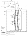
- FIG. 1 is a perspective view showing a hollow electrode of a microbial fuel cell according to Embodiment 1.
- FIG. It is a block diagram of a purification system. It is a block diagram of the microbial fuel cell which concerns on Embodiment 2 of this invention. It is a block diagram of the microbial fuel cell which concerns on Embodiment 3 of this invention. It is a block diagram of the microbial fuel cell which concerns on Embodiment 4 of this invention. It is a block diagram of the microbial fuel cell which concerns on Embodiment 5 of this invention. It is a block diagram of the microbial fuel cell which concerns on Embodiment 6 of this invention.
- FIG. (A), (b) is a top view which shows the upper support part and lower support part which comprise the support part of the microbial fuel cell which concerns on Embodiment 6.
- FIG. (A), (b) is a figure explaining the example of preparation of an upper support part and a lower support part. It is a block diagram of the microbial fuel cell which concerns on a 1st modification. It is a block diagram of the microbial fuel cell which concerns on a 2nd modification. It is a block diagram of the microbial fuel cell which concerns on a 3rd modification.
- a microbial fuel cell 10 according to Embodiment 1 of the present invention is a fuel cell that takes out electrical energy by decomposing organic substances in organic wastewater with microorganisms.
- Organic wastewater includes sewage, industrial wastewater and domestic wastewater.
- the organic waste water referred to here is waste water containing organic solids (for example, food residue, excrement, sludge that is a community of electricity-producing microorganisms).
- the microbial fuel cell 10 includes a reaction vessel 20 that stores the organic waste water 11, a hollow electrode 30 that is immersed in the organic waste water 11 in the reaction vessel 20, and a hollow electrode 30.
- An air supply unit 100 that supplies air into the cavity 42 is provided.
- the soot reaction container 20 is, for example, a bottomed box-shaped reaction tank, and is configured to store a certain amount of the organic waste water 11 supplied from the supply pump 90 in the container (in the tank).
- a water inlet 22 connected to a supply pump 90 is provided at the bottom 21 of the reaction vessel 20.
- a drain outlet 23 is provided in the upper part of the side wall of the reaction vessel 20.
- the organic waste water 11 is continuously supplied to the reaction vessel 20 through the water inlet 22 by the supply pump 90. For this reason, the organic waste water 11 flows upward from the bottom 21 of the reaction vessel 20.
- the hollow electrode 30 is disposed so that its longitudinal direction is in the vertical direction while being immersed in the organic waste water 11 in the reaction vessel 20.
- the organic waste water 11 flowing upward from the water inlet 22 at the bottom 21 of the reaction vessel 20 flows along the longitudinal direction of the hollow electrode 30. That is, a cross flow of the organic waste water 11 occurs with respect to the hollow electrode 30.
- the cross flow here means a flow parallel to the surface of the hollow electrode 30.
- the hollow electrode 30 includes a hollow fiber membrane 40 that is a hollow cylindrical tube serving as a base material, a cathode 50 formed on the outer periphery of the hollow fiber membrane 40, and an electrical insulator 60 formed on the outer periphery of the cathode 50. And an anode 70 formed on the outer periphery of the electrical insulator 60.
- the hollow fiber membrane 40 has a hollow cylindrical shape having a hollow portion 42 therein, and is generally used for solid-liquid separation in wastewater treatment. Used as a separation membrane for separating liquid.
- a separation membrane for separating liquid.
- polyolefin such as polytetrafluoroethylene, polyvinylidene fluoride, and polyethylene can be used.
- the hollow fiber membrane 40 of the first embodiment is formed with an air supply port 41 (described later) at the upper end and closed at the lower end.
- the cathode 50 has a binder that can transmit protons such as Nafion (registered trademark) on the outer peripheral surface excluding the upper end and the lower end of the hollow fiber membrane 40 shown in FIG. They are mixed and coated. That is, the cathode 50 is an electrode containing platinum as a catalyst. Note that platinum has a catalytic action that promotes a reaction in which oxygen (O 2 ) is combined with protons (H + ) and electrons (e ⁇ ) to generate water (H 2 O).
- oxygen (O 2 ) oxygen
- H + protons
- e ⁇ electrons
- the electrical insulator 60 is formed in a thin film on the outer peripheral surface of the cathode 50 so as to allow protons to pass therethrough in order to insulate the cathode 50 from the anode 70. It is a thing. More specifically, the electrical insulator 60 is formed as follows. The hollow fiber membrane 40 on which the cathode 50 is formed on the outer peripheral surface is dipped in, for example, a solution in which Nafion is dispersed except for its upper end, and then pulled up and dried. Thereby, the electrical insulator 60 is formed in a thin film shape on the outer peripheral surface of the cathode 50.
- the reason for removing the upper end of the hollow fiber membrane 40 is to prevent a thin film-like electrical insulator 60 from being formed on the inner wall of the cavity portion 42 due to the solution entering the cavity portion 42. Further, instead of applying the Nafion solution to the cathode 50, the electric insulator 60 may be formed by winding a Nafion film.
- the soot anode 70 is obtained by coating the outer peripheral surface of the electrical insulator 60 with, for example, carbon powder mixed with a proton permeable binder such as a Nafion solution.
- the hollow fiber membrane 40 which becomes the base material of the hollow electrode 30 has flexibility.
- a cathode 50, an electrical insulator 60, and an anode 70 are laminated in that order in the thickness direction of each part to form a thin film.
- the hollow electrode 30 remains flexible. Due to the cross flow of the organic waste water 11 in the reaction vessel 20, the hollow electrode 30 sways in the horizontal direction (direction of arrow YA) and / or undulates in the vertical direction (direction of arrow YB) as shown in FIG. Shakes.
- the cathode 50 and the anode 70 are connected via an external circuit 95.
- the air supply unit 100 includes a delivery pump 110, an on-off valve 120, a pressure gauge 130 as a pressure measurement unit, a gas introduction pipe 150 in which these are arranged in order from the air supply side, Pressure control unit 140.
- the soot gas introduction pipe 150 is a pipe for introducing the atmosphere (a gas containing oxygen and nitrogen) into the cavity 42.
- the exhaust side of the gas introduction pipe 150 is connected to an air supply port 41 formed at the upper end of the hollow electrode 30.
- the soot delivery pump 110 is a pump that delivers the atmosphere.
- the on-off valve 120 is a valve that is installed on the air discharge side of the delivery pump 110 and opens and closes the gas introduction pipe 150.
- the pressure gauge 130 is a meter that measures the pressure in the cavity 42 of the hollow electrode 30.
- the pressure control unit 140 Based on the pressure measurement value measured by the pressure gauge 130, the pressure control unit 140 operates the delivery pump 110 so that the pressure value of the hollow portion 42 of the hollow electrode 30 becomes a separately set pressure setting value. In addition, the opening / closing of the opening / closing valve 120 is controlled.
- the pressure set value is set to a pressure value higher than the pressure value outside the hollow electrode 30, and has an upper limit value and a lower limit value.
- the pressure control unit 140 sets the opening / closing valve 120 to the “open” state and turns the delivery pump 110 on. Drive. Then, when the pressure measurement value measured by the pressure gauge 130 exceeds the upper limit value of the pressure setting value, the pressure control unit 140 sets the open / close valve 120 to the “closed” state and stops the delivery pump 110. Further, a control method that can finely adjust the degree of “opening” of the opening / closing valve according to the pressure measurement value between the upper and lower limit values of the preset pressure setting value may be used. Thereby, the pressure value in the cavity part 42 is set to a pressure value higher than the outside. Since the pressure in the hollow portion 42 is higher than the outside of the hollow fiber membrane 40, the organic waste water 11 does not enter the hollow portion 42.
- the anaerobic electricity producing microorganism B floating in the organic waste water 11 of the reaction vessel 20 and the anaerobic electricity producing microorganism B adhering to the anode 70 are organic in the organic waste water 11.
- the substance (CHO) is decomposed, and electrons (e ⁇ ) are released from the inside of the microorganism into the outside of the cell in the metabolic process.
- the electrons (e ⁇ ) are transferred to the anode 70 through the electron carrier M (c-type cytochrome, conductive wire, etc.), and further sent to the cathode 50 through the external circuit 95.
- protons (H + ) discharged from the cells of the microorganisms together with the release of electrons (e ⁇ ) into the organic waste water 11 pass through the electrical insulator 60 and move to the cathode 50.
- Oxygen (O 2 ) in the atmosphere supplied into the cavity 42 through the opening / closing valve 120 is combined with protons (H + ) and electrons (e ⁇ ) by the catalytic action of platinum at the cathode 50 to form water (H 2 O). That is, electrons flow from the anode 70 to the cathode 50 via the external circuit 95 and are consumed there. As a result, a continuous flow of electrons occurs in the external circuit 95 between the anode 70 and the cathode 50, and power generation continues.
- the microbial fuel cell 10 according to the first embodiment can be applied to the purification system 200 shown in FIG. 3 that purifies organic wastewater such as sewage, industrial wastewater, and domestic wastewater.
- the soot purification system 200 includes a sand basin 201, an initial sedimentation basin 202, an aeration reaction tank 203, a final sedimentation basin 204, and a disinfection unit 205.
- the dredged sand basin 201 removes sand and large garbage from organic wastewater.
- the first sedimentation basin 202 fine sand and organic solids that have passed through the sedimentation basin 201 are precipitated.
- the aeration reaction tank 203 the water that has flowed through the settling tank 202 is supplied first, and air is supplied thereto. Thereby, the decomposition
- sludge which is a community of aerobic microorganisms in the aeration reaction tank 203 is precipitated.
- the overflow water in the final sedimentation basin 204 is disinfected using, for example, a disinfectant such as chlorine. After that, disinfected water is discharged into rivers.
- the microbial fuel cell 10 includes a sedimentation basin 201 and a first sedimentation basin 202, a first sedimentation basin 202, a first sedimentation basin 202 and an aeration reaction tank 203, an aeration reaction tank 203 (in this case, an aeration tank). It is possible to install a separate anaerobic zone in the reaction tank 203), the final sedimentation tank 204, or the like.
- the microbial fuel cell 10 can perform power generation and treatment of organic substances at these installation locations.
- the hollow electrode 30 has the organic drainage 11 in contact with the anode 70 formed on the outer periphery thereof, and the cathode 50 has In this configuration, oxygen-containing gas (atmosphere) is supplied from the cavity 42. Basically, it is only necessary to secure a space where oxygen can be supplied in the cavity 42. Therefore, the hollow electrode 30 can be made thin. Thereby, the arrangement
- the pressure in the cavity 42 of the cathode 50 is higher than the external pressure, oxygen can be secured in the cavity 42 while suppressing the intrusion of the organic waste water 11 into the cavity 42. For this reason, on the cathode 50 side, the reaction of combining oxygen, electrons, and protons into water is continued, and power generation can be continued.
- the hollow electrode 30 is formed by sequentially forming the cathode 50, the electrical insulator 60, and the anode 70 on the outer periphery, it can be easily manufactured.
- the sludge yield of the anaerobic treatment by the anaerobic electricity producing microorganism is about 1/10 compared to the aerobic treatment by the aerobic electricity producing microorganism.
- an anaerobic electricity production microorganism is used as an electricity production microorganism in the organic waste water 11 of the reaction container 20, a sludge generation rate can be reduced compared with an aerobic process.
- the supply of the organic waste water 11 to the reaction vessel 20 may be as follows. After supplying a predetermined amount of the organic waste water 11 by the supply pump 90 and performing the treatment for a predetermined time, the waste water in the reaction vessel 20 is removed, and the organic waste water 11 is replenished in the reaction vessel 20 again.
- a simple supply method may be used.
- the microbial fuel cell 10 of Embodiment 2 includes a support portion 80 that supports the hollow electrode 30 in a reaction container 20 so as to be swingable. More specifically, the support unit 80 supports the hollow electrode 30 in a loose state in the reaction vessel 20.
- the support portion 80 includes an upper support portion 81 that supports the upper end portion of the hollow electrode 30, a lower support portion 82 that supports the lower end portion of the hollow electrode 30, A U-shaped arm 83 that holds the support portion 81 and the lower support portion 82 at a distance shorter than the length of the hollow electrode 30 is provided.
- the support 80 supports the hollow electrode 30 in the reaction vessel 20 so as to be swingable.
- the hollow electrode 30 can be shaken by the liquid flow around the hollow electrode 30, and the organic solid matter attached to the anode 70 of the hollow electrode 30 can be dropped. Therefore, excessive adhesion of organic solids to the anode 70 can be suppressed, and power generation performance and water treatment performance can be maintained over a long period of time. That is, it is possible to provide a microbial fuel cell that can realize long-term operation.
- the microbial fuel cell 10 includes an oxygen concentration meter 160 disposed in the gas introduction pipe 150 and an air supply control unit 170.
- the soot oxygen concentration meter 160 measures the oxygen concentration in the cavity 42 of the hollow electrode 30.
- the air supply control unit 170 controls the operation of the delivery pump 110 and the opening / closing of the opening / closing valve 120 so that the oxygen concentration in the cavity 42 becomes a predetermined specified value based on the concentration measurement value of the oximeter 160. To do.
- the air supply control unit 170 sets the opening / closing valve 120 to the “open” state when the concentration measurement value measured by the oximeter 160 is lower than the lower limit value of the specified value, and the delivery pump 110 Drive. Then, when the concentration measurement value measured by the oximeter 160 exceeds the upper limit value of the specified value, the air supply control unit 170 sets the open / close valve 120 to the “closed” state and stops the delivery pump 110. Further, a control method that can finely adjust the degree of “opening” of the open / close valve according to a preset value between the upper and lower limits of the oxygen concentration may be used. Thereby, the measured value of the oxygen concentration in the cavity 42 is maintained at the specified value. In addition, since the pressure in the cavity 42 is higher than the outside, the organic waste water 11 does not enter the cavity 42.
- the atmospheric supply control unit 170 is based on the concentration measurement value of the oximeter 160 and the hollow portion 42 of the hollow electrode 30.
- the operation of the delivery pump 110 and the opening / closing of the opening / closing valve 120 are controlled so that the oxygen concentration in the inside becomes a specified value. That is, the oxygen concentration in the cavity 42 of the hollow electrode 30 is maintained at a specified value. For this reason, the oxygen concentration on the cathode 50 side can be kept at a specified value. For this reason, on the cathode 50 side, the reaction in which oxygen, electrons, and protons are combined to form water is continued, and power generation can be stabilized.
- the prescribed value of the oxygen concentration may be a concentration value in which the oxygen supply amount of the atmospheric supply amount to the cathode 50 and the oxygen consumption amount at the cathode 50 match or approximate. That is, the specified value of the oxygen concentration in the hollow electrode 30 is set to a concentration value commensurate with the oxygen consumed at the cathode 50.
- the oxygen consumption efficiency is obtained from simulation calculations and experimental data. The concentration value corresponding to the obtained oxygen consumption efficiency can be set as the specified value.
- the microbial fuel cell 10 periodically uses a stirrer 180 (cross flow generation unit) that generates a cross flow on the outer peripheral surface of the hollow electrode 30 and a timer 184.
- a stirring control unit 185 that is a cross flow control unit that controls the generation of the cross flow by the stirrer 180 or the strength of the cross flow is provided.
- the timer 184 sends a signal for instructing the start of operation to the stirring control unit 185 when the preset usage time or time of the hollow electrode 30 or the preset time or time or date and time is reached. Output.
- the agitation controller 185 drives and controls the agitator 180 based on a signal from the timer 184.
- the timer 184 may be provided inside the stirring control unit 185.
- the soot stirrer 180 is disposed on the bottom 21 side of the reaction vessel 20 and agitates the organic waste water 11 inside the reaction vessel 20. Due to the stirring operation of the stirrer 180, the organic waste water 11 flows toward the upper side of the stirrer 180. Specifically, a cross flow of the organic waste water 11 that flows upward along the outer peripheral surface of the hollow electrode 30 occurs.
- the agitation control unit 185 periodically controls the generation of the cross flow by the agitator 180 or the strength of the cross flow by the timer 184.
- the agitation control unit 185 controls the agitator 180 so that the cross flow is generated once or a plurality of times for a predetermined short period (eg, several tens of seconds, several minutes, etc.). Thereafter, the agitation control unit 185 stops the agitator 180.
- the hollow electrode is periodically swung. Since the adhesion of the organic solid matter to the anode 70 of the hollow electrode 30 progresses with time, the stirring control unit 185 causes the timer 184 to periodically generate a cross flow on the outer peripheral surface of the anode 70 or the cross The agitator 180 is controlled so as to enhance the flow. Thereby, the organic solid substance adhering to the outer peripheral surface of the anode 70 can be removed. Therefore, adhesion of organic solid matter to the anode 70 or the like can be suppressed, and the power generation performance can be maintained for a long time.
- the stirrer 180 is used as the cross flow generator, but the present invention is not limited to this.
- a circulation pump that circulates the organic waste water 11 in the reaction vessel 20 may be used as the cross flow generator. By driving the circulation pump, a cross flow of the organic waste water 11 flowing along the outer peripheral surface of the hollow electrode 30 is generated inside the reaction vessel 20.
- a gas not containing oxygen may be supplied into the reaction vessel 20 by using, for example, a gas supply pump.
- a cross flow to the outer peripheral surface of the hollow electrode 30 may be generated by aeration of a gas not containing oxygen.
- the microbial fuel cell 10 of the fifth embodiment uses a swing mechanism 190 instead of the stirrer 180 of the fourth embodiment.
- the microbial fuel cell 10 uses the swing mechanism 190 that swings the support portion 80 in the lateral direction (the direction of the arrow YA) and the timer 184 to periodically turn on the swing mechanism 190. And a swing control unit 195 that performs Off control.
- the timer 184 may be provided inside the swing control unit 195.
- the hollow electrode 30 is rocked by periodically controlling the rocking mechanism 190 on-off.
- the organic solid substance adhering to the outer peripheral surface of the anode 70 can be removed. Therefore, adhesion of organic solid matter to the anode 70 or the like can be suppressed, and the power generation performance can be maintained for a long time.
- the swing mechanism 190 swings the support portion 80 in the lateral direction
- the present invention is not limited to this.
- the swing mechanism 190 may swing the support portion 80 in the vertical direction, or may swing in the horizontal direction and the vertical direction.
- the rocking mechanism 190 may be rocked continuously instead of being controlled by a timer.
- the support portion 80 supports a plurality of (four in the present embodiment) hollow electrodes 30 in a swingable manner.
- another hollow electrode 30 exists on the back side of the central hollow electrode 30 (the back side in the drawing of FIG. 8), but the hollow electrode 30 is hidden and cannot be seen. The illustration is omitted.
- the support portion 80 includes an upper support portion 81 that supports the upper end portions of the four hollow electrodes 30, a lower support portion 82 that supports the lower end portions of the four hollow electrodes 30, and an upper support portion 81 and a lower support. And a U-shaped arm 83 that holds the portion 82 at a distance shorter than the length of the hollow electrode 30.
- the heel support portion 81 is formed in a flat plate shape as shown in FIG.
- the lower support portion 82 is formed in a flat plate shape as shown in FIG. 9B, and as shown in FIG. 10B, a circular through hole 85 is formed at a location surrounded by the four hollow electrodes 30. Prepare.
- a manufacturing method of the upper support portion 81 and the lower support portion 82 will be described.
- the upper ends of the four hollow electrodes 30 are attached to a melted thermoplastic resin material filled in a bowl-shaped mold (not shown), and the resin material is cured.
- a resin fixing portion 84 is formed at the upper end portions of the four hollow electrodes 30 as shown in FIG.
- the lower end portions of the four hollow electrodes 30 on which the soot resin fixing portions 84 are formed are attached to the melted thermoplastic resin material filled in the soot-shaped mold, and the resin material is cured. As a result, the lower support portion 82 is formed at the lower end portions of the four hollow electrodes 30 as shown in FIG.
- the bar part which protruded upwards is formed in the bottom center part of the bowl-shaped metal mold
- the cross flow of the organic waste water 11 from the paddle stirrer 180 passes through the through hole 85 of the lower support portion 82, the cross flow is also supplied to the inner portion surrounded by the four hollow electrodes 30. That is, the cross flow is also supplied to the outer peripheral surfaces of the four hollow electrodes 30 facing each other that are hidden from the outside. Therefore, it is possible to suppress the excessive adhesion of the organic solid material not only to the surface portion exposed to the outside of the bundled hollow electrode 30 but also to the inner surface portion hidden from the outside in the four hollow electrodes 30. .
- both the power generation amount and the water treatment amount can be achieved. Can be increased. Therefore, the power generation efficiency per unit volume and the water treatment efficiency can be further improved. Further, since the plurality of hollow electrodes 30 are supported in the reaction vessel 20 so as to be swingable, the plurality of hollow electrodes 30 can be swung by the surrounding liquid flow, and the organic to the anode 70 can be swung. The excessive adhesion of the conductive solid can be suppressed, and the power generation performance can be maintained for a long time.
- the through hole 85 is not limited to a circular shape.
- various shapes such as a rectangular shape, a triangular shape, and a crescent shape may be used.
- a plurality of through holes may be formed.
- the support portion 80 supports the four hollow electrodes 30, but is not limited to four.
- the support unit 80 may support a plurality of hollow electrodes 30 other than four, or may support a large number such as several tens or hundreds. Even when a large number of hollow electrodes 30 are supported in this way, through holes 85 may be formed at the locations of the lower support portions 82 between the adjacent hollow electrodes 30.
- the hollow electrodes 30 are connected in parallel to the external circuit 95, but may be connected in series.
- the reaction container 20 of each embodiment mentioned above should just be a container which can immerse the hollow electrode 30 in the organic waste water 11, and is not caught by the name.
- the reaction container 20 may be a cartridge type container, a module type container, or the like that can be attached to and detached from a pipe through which the organic waste water 11 flows.
- the microbial fuel cell 10 of each embodiment described above includes the reaction vessel 20, the hollow electrode 30, and the air supply unit 100, the microbial fuel cell 10 may be configured without the reaction vessel 20. That is, the microbial fuel cell 10 can be used by immersing the hollow electrode 30 in an existing sedimentation basin or storage tank instead of the reaction vessel 20.
- the hollow fiber membrane 40 has a hollow cylindrical shape.
- the hollow fiber membrane 40 is not limited to this, and may have a hollow shape and a cross section of various shapes such as a rectangular shape, an elliptical shape, and an oval shape. Further, the hollow fiber membrane 40 may have a shape or size different from that of the end portion in the middle thereof.
- the cylindrical body is the hollow fiber membrane 40, but the present invention is not limited to this.
- the cylinder may be a microfiltration membrane (MF membrane), an ultrafiltration membrane (UF membrane), a nano membrane (NF membrane), or the like.
- the cylindrical body may be a material having at least oxygen permeability such as a fluororesin tube and a silicon tube.
- the water inlet 22 is disposed at the bottom 21 of the reaction vessel 20, but may be disposed at the side of the reaction vessel 20, the top, or the like.
- the hollow electrode 30 is arranged in the reaction vessel 20 with the longitudinal direction thereof being the vertical direction, but may be arranged sideways or obliquely.
- the microbial fuel cell 10 according to the first modification is immersed in the organic waste water 11 of the reaction vessel 20 with the hollow electrode 30 bent in a U shape by the support portion 80.
- the structure is supported.
- the support portion 80 holds both ends of the hollow electrode 30 bent in a U shape, and supports the hollow electrode 30 such that both ends are located above the liquid level of the organic drainage 11.
- the microbial fuel cell 10 includes a stirrer 180 ⁇ / b> A on the side wall of the reaction vessel 20.
- the stirrer 180 ⁇ / b> A generates a flow of the organic waste water 11 in the space between the U-shapes of the hollow electrode 30.
- the flow of the organic waste water 11 is generated in the front-rear direction (the direction of the arrow YC) in FIG. Thereby, the excessive adhesion of the organic solid substance to the surface part which the U-shaped hollow electrode 30 opposes can be suppressed.
- the microbial fuel cell 10 according to the second modification is configured using a cathode 50 ⁇ / b> A in which a hollow electrode 30 is formed in a hollow shape with a conductive polymer material.
- the hollow electrode 30 includes a cathode 50A formed in a hollow shape by a conductive polymer material, an electric insulator 60 formed on the outer periphery of the cathode 50A, and an electric insulation. It is formed in a three-layer structure with the anode 70 formed on the outer periphery of the body 60.
- the cathode 50A formed of a conductive polymer material has both a function as a separation membrane and a function as an electrode. For this reason, the positive electrode which can permeate
- a silicon tube having a conductive performance mixed with a conductive material such as carbon black can be used with the same concept.
- the microbial fuel cell 10 includes a gas outlet tube 155 communicated with the other end side opposite to the one end side having the air supply port 41 of the hollow electrode 30, and a gas outlet And an open / close valve 162 disposed on the pipe 155.
- the delivery pump 110 is always operating, and the atmospheric delivery is continued.
- the soot gas outlet pipe 155 is a pipe for leading out the atmosphere in the hollow portion 42 of the hollow electrode 30, and is connected to the lower end of the hollow electrode 30.
- the on-off valve 162 is a valve that can adjust the opening degree of the gas outlet pipe 155. By adjusting the opening degree of the on-off valve 162 by the pressure control unit 140, it is possible to maintain the state in which the pressure of the cavity 42 is higher than that of the outside while allowing air to flow through the cavity 42 of the hollow electrode 30.
- the soot pressure control unit 140 controls the opening degree of the on-off valve 162 so that the pressure value of the hollow portion 42 of the hollow electrode 30 measured by the pressure gauge 130 becomes the pressure set value. Specifically, in a state where the delivery pump 110 is always operating, when the measured pressure value is lower than the lower limit value of the pressure setting value, the opening degree of the on-off valve 162 is decreased, and the measured pressure value is the pressure setting value. When the upper limit of the value is exceeded, the opening degree of the on-off valve 162 is increased. Thereby, the pressure value in the cavity part 42 is maintained at a pressure value higher than the outside.
- the microbial fuel cell 10 According to the microbial fuel cell 10 according to the third modification, it is possible to constantly pass the atmosphere through the cavity 42 while maintaining the pressure of the cavity 42 of the hollow electrode 30 higher than the outside. That is, oxygen contained in the atmosphere can be constantly supplied to the cavity 42 of the hollow electrode 30. For this reason, on the cathode 50 side, the reaction in which oxygen, electrons, and protons are combined to form water is continued, and power generation can be stabilized.
- water generated by the reaction at the cathode 50 may be accumulated in the cavity 42.
- the water is excluded from below. Is also possible and effective.
- the hollow electrode 30 is supplied with air from the upper end, but may be configured such that air is supplied from the lower end.
- the hollow fiber membrane 40 is configured such that the cathode 50, the electrical insulator 60, and the anode 70 are stacked on the outer peripheral surface and are not stacked on the upper end and the lower end.
- the present invention is not limited to this configuration.
- the hollow fiber membrane 40 may have a structure in which the cathode 50, the electrical insulator 60, and the anode 70 are laminated on at least one of the upper end and the lower end thereof.
- the cathode 50 and the anode 70 are formed by carbon coating.
- the conductor is formed by foaming without using an expensive binder such as a Nafion solution at the time of coating. It is also possible to provide a physical structure through which voids are provided between the particles so that protons or a liquid containing protons can pass through.
- the film may be formed by a method other than sputtering such as vacuum deposition.
- a carbon material having gas permeability and conductivity for example, carbon paper, carbon cloth, carbon felt, carbon blade hose, carbon blade tape, etc.
- the electrical insulator 60 may be formed by applying a mixture of powder filter paper and a binder material (a material capable of transmitting protons such as a Nafion solution) to the outer peripheral surface of the cathode 50. Further, at the time of coating, an inexpensive resin may be foamed without using an expensive binder such as a Nafion solution to ensure a physical structure through which protons or a liquid containing protons can permeate.
- the electrical insulator 60 may be made of a material having voids such as a glass fiber blade hose, an aramid fiber blade hose, filter paper, and the like.
- the electrical insulator 60 may be formed by vapor-depositing an electrical insulating material that can transmit protons on the outer peripheral surface of the cathode 50 by sputtering.
Landscapes
- Life Sciences & Earth Sciences (AREA)
- Chemical & Material Sciences (AREA)
- Chemical Kinetics & Catalysis (AREA)
- General Chemical & Material Sciences (AREA)
- Electrochemistry (AREA)
- Engineering & Computer Science (AREA)
- Sustainable Energy (AREA)
- Sustainable Development (AREA)
- Manufacturing & Machinery (AREA)
- Microbiology (AREA)
- Fuel Cell (AREA)
- Health & Medical Sciences (AREA)
- Molecular Biology (AREA)
- Biodiversity & Conservation Biology (AREA)
- Hydrology & Water Resources (AREA)
- Environmental & Geological Engineering (AREA)
- Water Supply & Treatment (AREA)
- Organic Chemistry (AREA)
- Biochemistry (AREA)
Abstract
【課題】電池の単位体積当たりの発電効率が向上した微生物燃料電池を提供する。 【解決手段】微生物燃料電池10は、内部に空洞部42を備える中空筒形状に形成されるとともに、空洞部42の一端に大気の給気口41が形成され、且つ有機性排水11中に浸漬された中空状電極30と、空洞部42に大気を供給する大気供給部100と、を備える。中空状電極30は、筒状に形成されたカソード50と、カソード50の外周に形成された電気絶縁体60と、電気絶縁体60の外周に形成されたアノード70とを備える。
Description
本発明は、微生物燃料電池に関する。
近年、微生物の代謝機能を利用して有機性排水中の有機物質から電力を生産する微生物燃料電池が注目されている。微生物燃料電池では、有機物質を分解すると同時に電気エネルギーを生成できる利点があり、実排水のように有機性固形物(電気産生微生物を含む)が含まれる雑多な汚水を燃料源に使用して、発電と汚水処理との両方を実現したいとの目的がある。
特許文献1に開示された微生物燃料電池としては、1槽型(single-chamber)と2槽型(double-chamber)とがある。
1槽型として代表的なエアーカソードタイプの微生物燃料電池は、平板状のアノード(マイナス極)と、酸素透過性を有するエアカソード(酸素正極)と呼ばれる平板状のカソード(プラス極)とが反応槽の両端に対向して互いに平行に配置された平行平板型の構成を有している。カソードの一方の面(外面)は大気に晒されている。カソードの他方の面(アノード側の面)には、触媒として白金(Pt)が担持されている。さらに、カソードの白金担持面には、プロトン(水素イオン)のみを透過するプロトン交換膜が設けられている。また、アノードには、有機性排水中の有機物質や、電子放出機能を有する電気産生微生物が接触する。なお、アノードとカソードとは外部回路を介して接続されている。
2槽型の微生物燃料電池は、反応槽内がプロトン交換膜によりアノード槽とカソード槽の2つに分離され、アノード槽内の有機性排水中に浸漬された平板状のアノードと、カソード槽内の溶液中に浸漬された平板状のカソードとが互いに平行に配置された平行平板型の構成を有している。カソードの表面には、触媒として白金が担持されている。カソード槽内の溶液は、アノード槽内からプロトン交換膜を透過したプロトンが存在する。この溶液中に酸素が供給されている。また、アノードとカソードは外部回路を介して接続されている。
また、上述した平行平板型の電極とは異なる形態として、筒状電極を備える微生物燃料電池が特許文献2に開示されている。特許文献2の微生物燃料電池は、円筒形状の隔膜の外周面にカソードを形成し且つ内周面にアノードを形成した筒状電極を備え、筒状電極のアノード側の空洞内に実排水が供給され、筒状電極の外周のカソードが酸素に晒される構成を有している。
特許文献1に開示された1槽型及び2槽型の微生物燃料電池は、アノード及びカソードが平行平板型に構成されたものである。このような、平行平板型の微生物燃料電池において、電池の単位体積当たりの発電効率を向上させるためには、アノード及びカソードの面積(電極面積)を広げ、且つ両電極の間隔を狭くする必要がある。しかし、そうすることで反応槽内の両電極間に形成される排水の流路の抵抗(流路抵抗)が増加し、排水の流速が低下する。このため、実排水中の有機性固形物が電極(特にアノード)に過剰に付着して両電極間の流路が閉塞する場合がある。これにより、例えば電極面に液流の無い箇所が生じる送液不良、電極間を液が流れない液短絡などが生じ、発電能力が低下する。このような状態を放置していては、電池の単位体積当たりの発電効率を向上させることができないという問題がある。
また、特許文献2に開示された微生物燃料電池は、アノードが空洞内周面に形成され且つカソードが外周面に形成された筒状電極を備える。この筒状電極の場合には、同じ大きさの平行平板型の電極、つまりアノード電極面上での排水の流路抵抗を同じにして、且つ電極体積を同じにした場合と比べて、平行平板型よりも電極の表面積が大きい。よって、表面積が大きい分だけ、電池の単位体積当たりの発電効率が高いと言える。
特許文献2の微生物燃料電池において、電極面積を増やして電池の単位体積当たりの発電効率をさらに向上させるために、筒状電極を細くして増設することが考えられる。しかし、筒状電極を細くしてアノードの空洞径を小さくすると、実排水が通る空洞内に微生物などの有機固形物が付着して液詰まりし易くなる。このため、筒状電極を細くすることができない。したがって、特許文献2に開示された微生物燃料電池では、筒状電極を細くして、電池の単位体積当たりの発電効率を向上させることができない。
本発明は、上記課題を解決するためになされたものであり、電池の単位体積当たりの発電効率が向上した微生物燃料電池を提供することを目的とする。
本発明に係る微生物燃料電池は、
有機性排水中の有機物質を微生物により分解して電気エネルギーを取り出す微生物燃料電池であって、
内部に空洞部を備える中空筒形状に形成されるとともに、前記空洞部の一端に大気の給気口が形成され、且つ有機性排水中に浸漬された中空状電極と、
前記空洞部に大気を供給する大気供給部と、
を備え、
前記中空状電極は、筒状に形成されたカソードと、前記カソードの外周に形成された電気絶縁体と、前記電気絶縁体の外周に形成されたアノードとを備える、
ことを特徴とする。
有機性排水中の有機物質を微生物により分解して電気エネルギーを取り出す微生物燃料電池であって、
内部に空洞部を備える中空筒形状に形成されるとともに、前記空洞部の一端に大気の給気口が形成され、且つ有機性排水中に浸漬された中空状電極と、
前記空洞部に大気を供給する大気供給部と、
を備え、
前記中空状電極は、筒状に形成されたカソードと、前記カソードの外周に形成された電気絶縁体と、前記電気絶縁体の外周に形成されたアノードとを備える、
ことを特徴とする。
本発明によれば、電池の単位体積当たりの発電効率が向上した微生物燃料電池を提供することができる。
以下、本発明の実施の形態について図面を参照して詳細に説明する。
(実施の形態1)
本発明の実施の形態1に係る微生物燃料電池10は、有機性排水中の有機物質を微生物により分解して電気エネルギーを取り出す燃料電池である。
本発明の実施の形態1に係る微生物燃料電池10は、有機性排水中の有機物質を微生物により分解して電気エネルギーを取り出す燃料電池である。
有機性排水としては、下水、産業排水、生活排水などが含まれる。なお、ここでいう有機性排水は、有機性固形物(例えば、食物残渣、排泄物、電気産生微生物の群集である汚泥など)を含む排水である。
微生物燃料電池10は、図1に示すように、有機性排水11を貯留する反応容器20と、反応容器20内の有機性排水11中に浸漬された中空状電極30と、中空状電極30の空洞部42内に大気を供給する大気供給部100とを備える。
反応容器20は、例えば有底箱状の反応槽であり、供給ポンプ90から供給される有機性排水11を容器内(槽内)に一定量貯留するように構成されている。反応容器20の底部21には、供給ポンプ90に接続された注水口22を備える。反応容器20の側壁上部には、反応容器20における水量上限値を超えた分の有機性排水11を排出するための排水口23を備える。
有機性排水11は、供給ポンプ90により、注水口22を介して反応容器20に連続して供給される。このため、有機性排水11は、反応容器20の底部21から上方に向けて流動する。
中空状電極30は、反応容器20内の有機性排水11中に浸漬された状態で、その長手方向を上下方向に向けて配置されている。これにより、反応容器20の底部21の注水口22から上方に向かう有機性排水11が中空状電極30の長手方向に沿って流れる。つまり、中空状電極30に対して、有機性排水11のクロスフローが生じる。なお、ここでいうクロスフローとは、中空状電極30の表面に対して平行な流れを意味する。
中空状電極30は、基材となる中空円筒状の筒体である中空糸膜40と、中空糸膜40の外周に形成されたカソード50と、カソード50の外周に形成された電気絶縁体60と、電気絶縁体60の外周に形成されたアノード70とを有する。
中空糸膜40は、図2に示すようにその内部に空洞部42を備えた中空円筒形状であり、一般には、排水処理の固液分離用に使用されるものであるが、ここでは気体と液体とを分離する分離膜として使用している。分離膜の材料としては、例えば、ポリテトラフルオロエチレン、ポリフッ化ビニリデン、ポリエチレン等のポリオレフィン系などが使用可能である。この実施の形態1の中空糸膜40は、図1に示すように、その上端には後述する給気口41が形成され、その下端が閉塞されたものである。
カソード50は、図1に示す中空糸膜40の上端及び下端を除く外周面に、例えばカーボンの表面上に白金を担持させた粒子をナフィオン(登録商標)溶液等のプロトンを透過可能なバインダーと混ぜて塗工したものである。つまり、カソード50は、触媒としての白金を含む電極である。なお、白金は、酸素(O2)とプロトン(H+)及び電子(e-)とを結合させて水(H2O)を生成する反応を促進させる触媒作用を有する。
電気絶縁体60は、図1、図2に示すように、カソード50とアノード70との間を絶縁するために、カソード50の外周面に、プロトンを透過しうる電気絶縁材を薄膜状に形成したものである。より詳しくは、電気絶縁体60は次のようにして形成される。カソード50が外周面に形成された中空糸膜40を、その上端を除いて、例えばナフィオンを分散させた溶液中に浸した後に、引き上げ、乾燥させる。これにより、カソード50の外周面に電気絶縁体60が薄膜状に形成される。中空糸膜40の上端を除いた理由は、空洞部42内に溶液が入り込むことにより、空洞部42の内壁に薄膜状の電気絶縁体60が形成されることを防止するためである。また、カソード50に対して、ナフィオン溶液を塗布するのでなく、ナフィオン膜を巻き付けて電気絶縁体60を形成しても構わない。
アノード70は、図1、図2に示すように、電気絶縁体60の外周面に、例えばカーボン粉末をナフィオン溶液等のプロトンを透過可能なバインダーと混ぜて塗工したものである。
また、中空状電極30の基材となる中空糸膜40は、柔軟性を有する。中空糸膜40の外周には、カソード50、電気絶縁体60及びアノード70がその順に各部の厚さ方向に積層して薄膜状に形成されている。このため、中空状電極30は柔軟性を残している。反応容器20内の有機性排水11のクロスフローにより、中空状電極30は、図1に示すように横方向(矢印YAの方向)に揺れ及び/又は上下方向(矢印YBの方向)に波打つ様に揺れる。
また、図1に示すように、カソード50とアノード70は、外部回路95を介して接続されている。
大気供給部100は、図1に示すように、送出ポンプ110と、開閉バルブ120と、圧力測定部である圧力計130と、これらが大気供給側から順に配設された気体導入管150と、圧力制御部140とを備える。
気体導入管150は、大気(酸素と窒素とを含む気体)を空洞部42内に導入するための管である。気体導入管150の排気側は、中空状電極30の上端に形成された給気口41に接続されている。
送出ポンプ110は、大気を送出するポンプである。開閉バルブ120は、送出ポンプ110の大気吐出側に設置され、且つ気体導入管150を開閉するバルブである。圧力計130は、中空状電極30の空洞部42内の圧力を測定する計器である。
圧力制御部140は、圧力計130にて測定された圧力測定値に基づいて、中空状電極30の空洞部42の圧力値が、別途設定された圧力設定値となるように送出ポンプ110の動作及び開閉バルブ120の開閉を制御する。圧力設定値は、中空状電極30の外部の圧力値よりも高い圧力値に設定されており、上限値と下限値とがある。
具体的には、圧力制御部140は、圧力計130により測定された圧力測定値が圧力設定値の下限値よりも低くなった場合に、開閉バルブ120を「開」状態とし、送出ポンプ110を駆動させる。そして、圧力制御部140は、圧力計130により測定された圧力測定値が圧力設定値の上限値を超えると、開閉バルブ120を「閉」状態とし、送出ポンプ110を停止させる。また、予め設定した圧力設定値の上下限値間の圧力測定値に応じ、開閉バルブの「開」の度合いを微調整できる制御方法でも構わない。これにより、空洞部42内の圧力値が外部よりも高い圧力値に設定される。空洞部42内の圧力が中空糸膜40の外部よりも高い圧力となっているので、空洞部42内には、有機性排水11が入り込むことはない。
ここで、この微生物燃料電池10による発電と有機物質の分解について、図1を用いて説明する。
図1に示すように、反応容器20の有機性排水11中を浮遊する嫌気性の電気産生微生物Bや、アノード70上に付着する嫌気性の電気産生微生物Bは、有機性排水11中の有機物質(CHO)を分解し、その代謝過程で微生物の細胞内から細胞外へ電子(e-)を放出する。その電子(e-)は、電子伝達体M(c型シトクロム、導電性ワイヤーなど)を介してアノード70に移され、さらに外部回路95を伝ってカソード50に送られる。
加えて、微生物の細胞から電子(e-)の放出と併せて有機性排水11中に排出されるプロトン(H+)は、電気絶縁体60を透過してカソード50に移る。
開閉バルブ120を介して空洞部42内に供給された大気中の酸素(O2)は、カソード50において白金の触媒作用によってプロトン(H+)及び電子(e-)と結合して水(H2O)となる。すなわち、電子はアノード70から外部回路95を経てカソード50に流れてそこで消費される。これにより、アノード70とカソード50間の外部回路95に連続した電子の流れが生じ、発電が継続する。
本実施の形態1の微生物燃料電池10は、下水、産業排水、生活排水などの有機性排水の浄化を行う図3に示す浄化システム200に適用することができる。
浄化システム200は、図3に示すように、沈砂池201、最初沈殿池202、曝気反応槽203、最終沈殿池204、消毒部205を備える。
沈砂池201は、有機性排水から砂や大きなゴミを除去する。最初沈殿池202では、沈砂池201を通過した細かな砂や有機性固形物を沈殿させる。曝気反応槽203では、最初沈殿池202を越流した水が供給され、これに空気が供給される。これにより、槽内の水に含まれる好気性の微生物による有機物の分解処理が行われる。最終沈殿池204では、曝気反応槽203中の好気性の微生物の群集である汚泥を沈殿させる。消毒部205では、この最終沈殿池204の越流水を例えば塩素などの消毒剤を用いて消毒する。その後、消毒済みの水が河川などへ放流される。
本実施の形態1の微生物燃料電池10は、沈砂池201と最初沈澱池202の間、最初沈殿池202、最初沈殿池202と曝気反応槽203との間、曝気反応槽203(この場合は曝気反応槽203内に別途嫌気ゾーンを設ける)、最終沈殿池204などに設置することが可能である。微生物燃料電池10は、これらの設置場所において、発電と、有機物質の処理とを行うことができる。
以上説明したように、本発明の実施の形態1に係る微生物燃料電池10によれば、中空状電極30は、その外周に形成されたアノード70に有機性排水11が接触し、カソード50には空洞部42内から酸素を含む気体(大気)が供給される構成である。空洞部42内は基本的には、酸素が供給できるスペースが確保されさえすればよい。従って、中空状電極30を細くすることができる。これにより、単位体積当たりの中空状電極30の配置数を増加させることができ、単位体積当たりの電極の表面積を増加させることができる。このため、電池の単位体積当たりの発電効率を向上させることができる。
また、カソード50の空洞部42内の圧力が外部の圧力よりも高いので、有機性排水11の空洞部42内への浸入を抑えながら、空洞部42内に酸素を確保することができる。このため、カソード50側において、酸素と電子とプロトンとが結合して水となる反応が継続され、発電が継続できる。
中空状電極30は、外周に、カソード50、電気絶縁体60、及びアノード70を順次に形成して構成されているので、簡易に作製できる。
嫌気性の電気産生微生物による嫌気処理の汚泥収率は、好気性の電気産生微生物による好気処理に比べて、1/10程度である。本実施の形態では、反応容器20の有機性排水11中における電気産生微生物として、嫌気性の電気産生微生物を用いるので、好気処理に比べて汚泥発生率を減らすことができる。
また、反応容器20への有機性排水11の供給については、次のようにしてもよい。供給ポンプ90により所定量の有機性排水11をまとめて供給し、所定時間の処理を行った後、反応容器20内の排水を排除し、再度反応容器20内に有機性排水11を補充する間欠的な供給方法でも良い。
(実施の形態2)
続いて、本発明の実施の形態2に係る微生物燃料電池10について説明する。なお、以下の説明において、実施の形態1と共通する構成要素等については、同一の符号を付す。
続いて、本発明の実施の形態2に係る微生物燃料電池10について説明する。なお、以下の説明において、実施の形態1と共通する構成要素等については、同一の符号を付す。
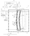
実施の形態2の微生物燃料電池10は、図4に示すように、反応容器20内において中空状電極30を揺動可能に支持する支持部80を備える。より詳しくは、支持部80は、反応容器20内において中空状電極30を緩んだ状態で支持する。
具体的には、支持部80は、図4に示すように、中空状電極30の上端部を支持する上支持部81と、中空状電極30の下端部を支持する下支持部82と、上支持部81と下支持部82とを中空状電極30の長さよりも短い距離に保持するコの字形状のアーム83とを備える。
以上説明したように、本発明の実施の形態2に係る微生物燃料電池10によれば、支持部80は、反応容器20内において中空状電極30を揺動可能に支持する。このため、中空状電極30の周囲の液流により、中空状電極30を揺らすことができ、中空状電極30のアノード70に付着した有機性固形物を落とすことができる。従って、アノード70への有機性固形物の過剰付着を抑制することができ、長期間に亘って発電性能と水処理性能とを維持できる。つまり、長期運転を実現できる微生物燃料電池を提供することができる。
(実施の形態3)
続いて、本発明の実施の形態3に係る微生物燃料電池10について説明する。なお、以下の説明において、実施の形態1、2と共通する構成要素等については、同一の符号を付す。
続いて、本発明の実施の形態3に係る微生物燃料電池10について説明する。なお、以下の説明において、実施の形態1、2と共通する構成要素等については、同一の符号を付す。
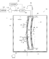
実施の形態3の微生物燃料電池10は、図5に示すように、気体導入管150に配設された酸素濃度計160と、大気供給制御部170とを備える。
酸素濃度計160は、中空状電極30の空洞部42の酸素濃度を測定する。大気供給制御部170は、酸素濃度計160の濃度測定値に基づいて、空洞部42内の酸素濃度が、予め設定した規定値となるように送出ポンプ110の動作及び開閉バルブ120の開閉を制御する。
具体的には、大気供給制御部170は、酸素濃度計160により測定された濃度測定値が規定値の下限値よりも低くなった場合に、開閉バルブ120を「開」状態とし、送出ポンプ110を駆動させる。そして、大気供給制御部170は、酸素濃度計160により測定された濃度測定値が規定値の上限値を超えると、開閉バルブ120を「閉」状態とし、送出ポンプ110を停止させる。また、予め設定した酸素濃度の上下限値間の値に応じ、開閉バルブの「開」の度合いを微調整できる制御方法でも構わない。これにより、空洞部42内の酸素の濃度測定値が規定値に維持される。なお、空洞部42内の圧力は、外部よりも高い圧力となっているので、空洞部42内には、有機性排水11が入り込むことはない。
以上説明したように、本発明の実施の形態3に係る微生物燃料電池10によれば、大気供給制御部170は、酸素濃度計160の濃度測定値に基づいて、中空状電極30の空洞部42内の酸素濃度が規定値となるように送出ポンプ110の動作及び開閉バルブ120の開閉を制御する。つまり、中空状電極30の空洞部42内の酸素濃度が規定値に維持される。このため、カソード50側における酸素濃度を規定値に保つことができる。このため、カソード50側において、酸素と電子とプロトンとが結合して水となる反応が継続され、発電の安定化を図ることができる。
なお、酸素濃度の規定値としては、カソード50への大気供給量のうちの酸素の供給量と、カソード50での酸素の消費量とが一致又は近似した濃度値としてもよい。つまり、中空状電極30内の酸素濃度の規定値は、カソード50にて消費される酸素に見合った濃度値とする。例えば、酸素の消費効率を、シミュレーション計算や実験データから求める。この求めた酸素の消費効率に見合った濃度値を規定値とすることができる。
この場合には、中空状電極30の空洞部42内に供給された酸素の殆どがカソード50で消費され、空洞部42内の酸素が中空状電極30の筒膜部分を透過する量は少ないことから、嫌気性の電気産生微生物に与える影響は無視できる。
(実施の形態4)
続いて、本発明の実施の形態4に係る微生物燃料電池10について説明する。なお、以下の説明において、実施の形態1~3と共通する構成要素等については、同一の符号を付す。
続いて、本発明の実施の形態4に係る微生物燃料電池10について説明する。なお、以下の説明において、実施の形態1~3と共通する構成要素等については、同一の符号を付す。
実施の形態4の微生物燃料電池10は、図6に示すように、中空状電極30の外周表面上にクロスフローを発生させる攪拌機180(クロスフロー発生部)と、タイマー184を用いて定期的に攪拌機180によるクロスフローの発生又はそのクロスフローを強めるように制御するクロスフロー制御部である攪拌制御部185とを備える。
タイマー184は、中空状電極30の予め設定された単数若しくは複数の使用経過時間、又は、予め設定された単数若しくは複数の時刻若しくは日時などになると、動作開始を指示する信号を攪拌制御部185に出力する。攪拌制御部185は、タイマー184からの信号に基づいて、攪拌機180を駆動制御する。なお、タイマー184は攪拌制御部185の内部に配設されたものであってもよい。
攪拌機180は、反応容器20の底部21側に配設され、反応容器20の内部の有機性排水11を攪拌するものである。攪拌機180の攪拌動作により、攪拌機180の上方に向けて有機性排水11が流れる。詳しくは、中空状電極30の外周表面に沿って上方向に流動する有機性排水11のクロスフローが発生する。
攪拌制御部185は、タイマー184により定期的に、攪拌機180によるクロスフローの発生又はそのクロスフローを強めるように制御する。攪拌制御部185は、クロスフローの発生を所定の短期間(例えば、数十秒、数分など)1回又は複数回行うように攪拌機180を制御する。その後、攪拌制御部185は、攪拌機180を停止させる。
以上説明したように、本発明の実施の形態4に係る微生物燃料電池10によれば、定期的に中空状電極を揺動させる。中空状電極30のアノード70などへの有機性固形物の付着が経時的に進むので、攪拌制御部185は、タイマー184により定期的にアノード70の外周表面上にクロスフローを発生させる又はそのクロスフローを強めるように攪拌機180を制御する。これにより、アノード70の外周表面に付着した有機性固形物を除去できる。従って、アノード70などへの有機性固形物の付着を抑えることができ、発電性能を長期間に亘り維持することができる。
また、実施の形態4では、クロスフロー発生部として攪拌機180を用いているが、これに限定されない。クロスフロー発生部として、例えば反応容器20内の有機性排水11を循環させる循環ポンプを用いてもよい。循環ポンプの駆動により、反応容器20の内部に、中空状電極30の外周表面に沿って流動する有機性排水11のクロスフローが発生する。また、クロスフロー発生部として、例えばガス供給ポンプを用いて、酸素を含まないガスを反応容器20の内部に供給してもよい。酸素を含まないガスの曝気により、中空状電極30の外周表面へのクロスフローを発生させてもよい。
(実施の形態5)
続いて、本発明の実施の形態5に係る微生物燃料電池10について説明する。なお、以下の説明において、実施の形態1~4と共通する構成要素等については、同一の符号を付す。
続いて、本発明の実施の形態5に係る微生物燃料電池10について説明する。なお、以下の説明において、実施の形態1~4と共通する構成要素等については、同一の符号を付す。
実施の形態5の微生物燃料電池10は、図7に示すように、実施の形態4の攪拌機180に替えて揺動機構190を用いる。
また、実施の形態5の微生物燃料電池10は、支持部80を横方向(矢印YAの方向)に揺動させる揺動機構190と、タイマー184を用いて定期的に揺動機構190をOn-Off制御する揺動制御部195とを備える。なお、タイマー184は揺動制御部195の内部に配設されたものであってもよい。
以上説明したように、本発明の実施の形態5に係る微生物燃料電池10によれば、定期的に揺動機構190をOn-Off制御して、中空状電極30を揺動させる。これにより、アノード70の外周表面に付着した有機性固形物を除去できる。従って、アノード70などへの有機性固形物の付着を抑えることができ、発電性能を長期間に亘り維持することができる。
なお、揺動機構190は、支持部80を横方向に揺動させているが、これに限定されない。揺動機構190は、例えば、支持部80を上下方向に揺動させてもよいし、横方向及び上下方向に揺動させてもよい。また、揺動機構190は、タイマー制御ではなく連続的に揺動させてもよい。
(実施の形態6)
続いて、本発明の実施の形態6に係る微生物燃料電池10について説明する。なお、以下の説明において、実施の形態1~5と共通する構成要素等については、同一の符号を付す。
続いて、本発明の実施の形態6に係る微生物燃料電池10について説明する。なお、以下の説明において、実施の形態1~5と共通する構成要素等については、同一の符号を付す。
実施の形態6の微生物燃料電池10では、支持部80は、図8に示すように、複数本(本実施の形態では4本)の中空状電極30を揺動可能に支持するものである。なお、図8では、中央の中空状電極30の裏側(図8の紙面奥側)に、中空状電極30がもう1本存在しているが、その中空状電極30が隠れて見えないため、図示を省略している。
支持部80は、4本の中空状電極30の上端部を支持する上支持部81と、4本の中空状電極30の下端部を支持する下支持部82と、上支持部81と下支持部82とを中空状電極30の長さよりも短い距離に保持するコの字形状のアーム83とを備える。
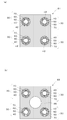
上支持部81は、図9(a)に示すように平板状に形成される。下支持部82は、図9(b)に示すように平板状に形成され、図10(b)に示すように、4本の中空状電極30に囲まれた箇所に円形の貫通穴85を備える。
ここで、上支持部81及び下支持部82の作製方法について説明する。4本の中空状電極30の上端部が、図示しない枡状の金型内に充填された溶解した熱可塑性樹脂材料中につけられ、その樹脂材料を硬化させる。これにより、4本の中空状電極30の上端部には、図9(a)に示すように、樹脂固定部84が形成される。
樹脂固定部84が形成された4本の中空状電極30の下端部が、枡状の金型内に充填された溶解した熱可塑性樹脂材料中につけられ、その樹脂材料を硬化させる。これにより、4本の中空状電極30の下端部に、図9(a)に示すように、下支持部82が形成される。
そして、4本の中空状電極30の上端部側の樹脂固定部84は、図10(a)に一点鎖線で示す切断線CLにて切断され、図10(b)に示すように上支持部81が形成される。これにより、上支持部81には、4本の中空状電極30にそれぞれ連通する各給気口41が形成される。上支持部81及び下支持部82により、4本の中空状電極30が纏められている。そして、図10(b)に示すように、下支持部82における4本の中空状電極30に囲まれた箇所に円形の貫通穴85を形成する。なお、下支持部82を形成するための枡状の金型の底面中央箇所に上方に突出した棒部を形成しておき、下支持部82の硬化形成と同時に、その棒部が抜けた孔である貫通穴85を形成するようにしてもよい。
攪拌機180からの有機性排水11のクロスフローが、下支持部82の貫通穴85を通るため、4本の中空状電極30に囲まれる内側部分にもクロスフローが供給される。つまり、4本の中空状電極30において外部から隠れる各本の中空状電極30の対向する外周表面上にもクロスフローが供給される。よって、4本束ねた状態の中空状電極30の外側に露出する表面部分のみならず、4本の中空状電極30において外部から隠れる内側の表面部分への有機性固形物の過剰付着を抑制できる。
以上説明したように、本発明の実施の形態6に係る微生物燃料電池10によれば、中空状電極30を複数本(ここでは4本)にすることにより、発電量と水処理量の両方を増加させることができる。よって、単位体積当たりの発電効率及び水処理効率をさらに向上させることができる。また、反応容器20の内部において複数本の中空状電極30が揺動可能に支持されているので、複数本の中空状電極30をその周囲の液流により揺らすことができ、アノード70への有機性固形物の過剰付着を抑えることができ、発電性能を長期間に亘り維持することができる。
なお、貫通穴85は円形に限定されない。例えば、矩形状、三角形状、三日月形状など種々の形状であってもよい。また、複数個の貫通穴を形成しても構わない。
この実施の形態6では、支持部80は、4本の中空状電極30を支持しているが、4本に限定されない。支持部80は、中空状電極30を、4本以外の複数本支持するようにしてもよく、数十本、数百本など多数支持してもよい。このように多数の中空状電極30を支持する場合でも、隣接する中空状電極30間の下支持部82の箇所に貫通穴85を形成してもよい。
この実施の形態6では、外部回路95に対して各中空状電極30を並列に接続しているが、直列に接続してもよい。
なお、本発明は、上記各実施の形態に限定されず、本発明の要旨を逸脱しない範囲での種々の変更は勿論可能である。
前述した各実施の形態の反応容器20は、中空状電極30を有機性排水11中に浸漬可能な容器であればよく、その名称には捕らわれない。また、反応容器20は、有機性排水11が流れる配管に着脱可能なカートリッジ型の容器、モジュール型の容器などであってもよい。
前述した各実施の形態の微生物燃料電池10は、反応容器20と中空状電極30と大気供給部100とを備える構成としているが、反応容器20を具備しない構成であってもよい。つまり、反応容器20に替えて既存の沈殿池又は貯留槽などに中空状電極30を浸漬させて微生物燃料電池10を使用することができる。
前述した各実施の形態では、中空糸膜40が中空円筒形状であるとした。これに限らず、中空糸膜40は、中空形状であってその断面が矩形状、楕円状、長円状など種々の形状であってもよい。また、中空糸膜40は、その途中が端部と異なる形状や大きさであってもよい。
前述した各実施の形態では、筒体が中空糸膜40であるとしたが、これに限定されない。例えば、筒体は、精密ろ過膜(MF膜)、限外ろ過膜(UF膜)、ナノ膜(NF膜)などであってもよい。また、筒体は、フッ素樹脂チューブ、シリコンチューブなど、少なくとも酸素透過能を持つ材料であれば良い。
前述した各実施の形態では、注水口22は反応容器20の底部21に配置されているが、反応容器20の側部、天部などに配置されてもよい。
前述した各実施の形態では、中空状電極30は、その長手方向を上下方向にして反応容器20内に配置されているが、横向きや斜め向きに配置してもよい。
(第1変形例)
第1変形例に係る微生物燃料電池10は、図11に示すように、支持部80により、中空状電極30がU字状に曲げた状態で反応容器20の有機性排水11中に浸漬して支持される構成としている。支持部80は、U字状に曲げた状態の中空状電極30の両端を保持し、この両端が、有機性排水11の液面よりも上方に位置するようにして中空状電極30を支持する。また、微生物燃料電池10は、反応容器20の側壁に攪拌機180Aを備える。攪拌機180Aは、中空状電極30のU字状間の空間に有機性排水11の流動を発生させる。つまり、図11の紙面前後方向(矢印YCの方向)に有機性排水11の流動を発生させる。これにより、U字状の中空状電極30の対向する表面部分への有機性固形物の過剰付着を抑制できる。
第1変形例に係る微生物燃料電池10は、図11に示すように、支持部80により、中空状電極30がU字状に曲げた状態で反応容器20の有機性排水11中に浸漬して支持される構成としている。支持部80は、U字状に曲げた状態の中空状電極30の両端を保持し、この両端が、有機性排水11の液面よりも上方に位置するようにして中空状電極30を支持する。また、微生物燃料電池10は、反応容器20の側壁に攪拌機180Aを備える。攪拌機180Aは、中空状電極30のU字状間の空間に有機性排水11の流動を発生させる。つまり、図11の紙面前後方向(矢印YCの方向)に有機性排水11の流動を発生させる。これにより、U字状の中空状電極30の対向する表面部分への有機性固形物の過剰付着を抑制できる。
(第2変形例)
第2変形例に係る微生物燃料電池10は、図12に示すように、中空状電極30が、導電性高分子材料により中空状に形成されたカソード50Aを用いて構成される。具体的には、図12に示すように、中空状電極30は、導電性高分子材料により中空状に形成されたカソード50Aと、カソード50Aの外周に形成された電気絶縁体60と、電気絶縁体60の外周に形成されたアノード70との3層構造に形成される。導電性高分子材料により形成されたカソード50Aは、分離膜としての機能と電極としての機能の両方を具備する。このため、筒厚部分を酸素が透過可能な正極を実現でき、中空糸膜40を用いずに済む。従って、構成の簡素化を図ることができる。
第2変形例に係る微生物燃料電池10は、図12に示すように、中空状電極30が、導電性高分子材料により中空状に形成されたカソード50Aを用いて構成される。具体的には、図12に示すように、中空状電極30は、導電性高分子材料により中空状に形成されたカソード50Aと、カソード50Aの外周に形成された電気絶縁体60と、電気絶縁体60の外周に形成されたアノード70との3層構造に形成される。導電性高分子材料により形成されたカソード50Aは、分離膜としての機能と電極としての機能の両方を具備する。このため、筒厚部分を酸素が透過可能な正極を実現でき、中空糸膜40を用いずに済む。従って、構成の簡素化を図ることができる。
また、カーボンブラック等の導電性材料を混ぜた導電性能を有するシリコンチューブなどもこれと同じ概念で使用できる。
(第3変形例)
第3変形例に係る微生物燃料電池10は、図13示すように、中空状電極30の給気口41を有する一端側とは反対の他端側に連通された気体導出管155と、気体導出管155に配設された開閉バルブ162とを備える。送出ポンプ110は常時動作しており、大気の送出が継続される。
第3変形例に係る微生物燃料電池10は、図13示すように、中空状電極30の給気口41を有する一端側とは反対の他端側に連通された気体導出管155と、気体導出管155に配設された開閉バルブ162とを備える。送出ポンプ110は常時動作しており、大気の送出が継続される。
気体導出管155は、中空状電極30の空洞部42内の大気を導出するための管であり、中空状電極30の下端に接続されている。開閉バルブ162は、気体導出管155の開度を調整可能なバルブである。圧力制御部140が開閉バルブ162の開度を調整することにより、中空状電極30の空洞部42に大気を流通させつつ、空洞部42の圧力を外部よりも高くした状態を維持できる。
圧力制御部140は、圧力計130にて測定された中空状電極30の空洞部42の圧力値が圧力設定値となるように開閉バルブ162の開度を制御する。具体的には、送出ポンプ110が常時動作する状態において、圧力測定値が圧力設定値の下限値よりも低くなった場合に、開閉バルブ162の開度を小さくし、圧力測定値が圧力設定値の上限値を超えると、開閉バルブ162の開度を大きくする。これにより、空洞部42内の圧力値が外部よりも高い圧力値に維持される。
第3変形例に係る微生物燃料電池10によれば、中空状電極30の空洞部42の圧力を外部よりも高くした状態を維持しつつ、大気を常時、空洞部42を通過させることができる。つまり、中空状電極30の空洞部42に、大気に含まれる酸素を常時供給することができる。このため、カソード50側において、酸素と電子とプロトンとが結合して水となる反応が継続され、発電の安定化を図ることができる。
また、使用する中空状電極30の材料によっては、カソード50での反応により生成した水が空洞部42に蓄積する場合が考えられるが、第3変形例であれば下方からその水を排除することも可能であり、有効である。
前述した各実施の形態では、中空状電極30は、上端から大気が供給されているが、下端から大気が供給される構成であってもよい。
前述した各実施の形態では、中空糸膜40は、外周面にカソード50と電気絶縁体60とアノード70とを積層し、上端及び下端にそれらを積層しない構成としているが、この形態に限定されない。例えば、中空糸膜40は、その上端及び下端の少なくとも一方に、カソード50と電気絶縁体60とアノード70とを積層した構成であってもよい。
前述した各実施の形態では、カソード50及びアノード70は、カーボンの塗工にて形成されているが、塗工の際にナフィオン溶液等の高価なバインダーを使わずに、発泡処理にて導電体粒子間に空隙を設け、プロトン又はプロトンを含む液が透過可能な物理的構造を確保しても良い。また塗工以外にも、真空蒸着法などのスパッタ法以外の方法により形成してもよい。また、カソード50及びアノード70として、気体透過性及び導電性を有するカーボン材料(例えばカーボンペーパー、カーボンクロス、カーボンフエルト、カーボンブレードホース、カーボンブレードテープなど)を用いてもよい。
電気絶縁体60は、粉末ろ紙とバインダー材料(ナフィオン溶液等のプロトン透過可能な材料)とを混ぜたものをカソード50の外周面に塗工して形成したものであってもよい。また、塗工の際に、ナフィオン溶液等の高価なバインダーを使わずに安価な樹脂に発泡処理を施して、プロトン又はプロトンを含む液が透過可能な物理的構造を確保しても良い。また、電気絶縁体60は、ガラス繊維製ブレードホース、アラミド繊維製ブレードホース、ろ紙などの空隙のある材料を用いてもよい。また、電気絶縁体60は、スパッタ法により、プロトンを透過しうる電気絶縁材をカソード50の外周面に蒸着して形成されたものであってもよい。
10 微生物燃料電池
11 有機性排水
20 反応容器
21 底部
22 注水口
23 排水口
30 中空状電極
40 中空糸膜(筒体)
41 給気口
42 空洞部
50 カソード
50A カソード
60 電気絶縁体
70 アノード
80 支持部
81 上支持部
82 下支持部
83 アーム
84 樹脂固定部
85 貫通穴
90 供給ポンプ
95 外部回路
100 大気供給部
110 送出ポンプ
120 開閉バルブ
130 圧力計(圧力測定部)
140 圧力制御部
150 気体導入管
155 気体導出管
160 酸素濃度計(濃度測定部)
162 開閉バルブ
170 大気供給制御部
180 攪拌機(クロスフロー発生部)
184 タイマー
185 攪拌制御部(クロスフロー制御部)
190 揺動機構
195 揺動制御部
200 浄化システム
201 沈砂池
202 最初沈殿池
203 曝気反応槽
204 最終沈殿池
205 消毒部
B 電気産生微生物
CL 切断線
M 電子伝達体
11 有機性排水
20 反応容器
21 底部
22 注水口
23 排水口
30 中空状電極
40 中空糸膜(筒体)
41 給気口
42 空洞部
50 カソード
50A カソード
60 電気絶縁体
70 アノード
80 支持部
81 上支持部
82 下支持部
83 アーム
84 樹脂固定部
85 貫通穴
90 供給ポンプ
95 外部回路
100 大気供給部
110 送出ポンプ
120 開閉バルブ
130 圧力計(圧力測定部)
140 圧力制御部
150 気体導入管
155 気体導出管
160 酸素濃度計(濃度測定部)
162 開閉バルブ
170 大気供給制御部
180 攪拌機(クロスフロー発生部)
184 タイマー
185 攪拌制御部(クロスフロー制御部)
190 揺動機構
195 揺動制御部
200 浄化システム
201 沈砂池
202 最初沈殿池
203 曝気反応槽
204 最終沈殿池
205 消毒部
B 電気産生微生物
CL 切断線
M 電子伝達体
Claims (8)
- 有機性排水中の有機物質を微生物により分解して電気エネルギーを取り出す微生物燃料電池であって、
内部に空洞部を備える中空筒形状に形成されるとともに、前記空洞部の一端に大気の給気口が形成され、且つ有機性排水中に浸漬された中空状電極と、
前記空洞部に大気を供給する大気供給部と、
を備え、
前記中空状電極は、筒状に形成されたカソードと、前記カソードの外周に形成された電気絶縁体と、前記電気絶縁体の外周に形成されたアノードとを備える、
ことを特徴とする微生物燃料電池。 - 前記空洞部内の圧力を外部の圧力よりも高くするように制御する圧力制御部を備える、
ことを特徴とする請求項1に記載の微生物燃料電池。 - 有機性排水中の浸漬された前記中空状電極を揺動可能に支持する支持部を備える、
ことを特徴とする請求項1又は2に記載の微生物燃料電池。 - 前記支持部は、複数本の前記中空状電極を揺動可能に支持する、
ことを特徴とする請求項3に記載の微生物燃料電池。 - 前記空洞部内の酸素濃度を測定する濃度測定部を備え、
前記濃度測定部の濃度測定値に基づいて、前記空洞部内の酸素濃度が規定値となるように前記大気供給部による大気供給量を制御する大気供給制御部と、
を備える、
ことを特徴とする請求項1から4の何れか1項に記載の微生物燃料電池。 - 前記アノードの表面上にクロスフローを発生させるクロスフロー発生部と、
タイマーを用いて定期的に、前記クロスフロー発生部によるクロスフローの発生又はそのクロスフローを強めるように制御するクロスフロー制御部と、
を備える、
ことを特徴とする請求項1から5の何れか1項に記載の微生物燃料電池。 - 前記支持部を揺動させる揺動機構と、
連続的又はタイマーを用いて定期的に、前記中空状電極が揺動するように前記揺動機構を制御する揺動制御部と、
を備える、
ことを特徴とする請求項3又は4に記載の微生物燃料電池。 - 前記カソードは、導電性高分子材料により形成されている、又は導電性材料を含む高分子材料により形成されている、
ことを特徴とする請求項1から7の何れか1項に記載の微生物燃料電池。
Applications Claiming Priority (2)
| Application Number | Priority Date | Filing Date | Title |
|---|---|---|---|
| JP2014-034123 | 2014-02-25 | ||
| JP2014034123A JP2015159076A (ja) | 2014-02-25 | 2014-02-25 | 微生物燃料電池 |
Publications (1)
| Publication Number | Publication Date |
|---|---|
| WO2015129094A1 true WO2015129094A1 (ja) | 2015-09-03 |
Family
ID=54008439
Family Applications (1)
| Application Number | Title | Priority Date | Filing Date |
|---|---|---|---|
| PCT/JP2014/077096 Ceased WO2015129094A1 (ja) | 2014-02-25 | 2014-10-09 | 微生物燃料電池 |
Country Status (2)
| Country | Link |
|---|---|
| JP (1) | JP2015159076A (ja) |
| WO (1) | WO2015129094A1 (ja) |
Cited By (2)
| Publication number | Priority date | Publication date | Assignee | Title |
|---|---|---|---|---|
| WO2017149633A1 (ja) * | 2016-03-01 | 2017-09-08 | 株式会社日立製作所 | 水処理装置及びこれに用いる導電性多孔質炭素材料 |
| JP2019110100A (ja) * | 2017-12-20 | 2019-07-04 | 国立研究開発法人農業・食品産業技術総合研究機構 | 生物電気化学システム |
Families Citing this family (1)
| Publication number | Priority date | Publication date | Assignee | Title |
|---|---|---|---|---|
| CN115411325A (zh) * | 2022-09-27 | 2022-11-29 | 沈阳建筑大学 | 富集甲烷厌氧氧化产电互养共生微生物的导电中空纤维膜电化学装置及其方法 |
Citations (3)
| Publication number | Priority date | Publication date | Assignee | Title |
|---|---|---|---|---|
| JP2011065875A (ja) * | 2009-09-17 | 2011-03-31 | Kurita Water Ind Ltd | 微生物発電装置 |
| US20120276418A1 (en) * | 2009-07-17 | 2012-11-01 | Guangdong Institute Of Ecoenvironmental And Soil Sciences | Methods and devices for in-situ treatment of sediment simultaneous with microbial electricity generation |
| JP2013143305A (ja) * | 2012-01-12 | 2013-07-22 | Sekisui Chem Co Ltd | 膜・電極接合構造体、並びに微生物燃料電池モジュール |
-
2014
- 2014-02-25 JP JP2014034123A patent/JP2015159076A/ja active Pending
- 2014-10-09 WO PCT/JP2014/077096 patent/WO2015129094A1/ja not_active Ceased
Patent Citations (3)
| Publication number | Priority date | Publication date | Assignee | Title |
|---|---|---|---|---|
| US20120276418A1 (en) * | 2009-07-17 | 2012-11-01 | Guangdong Institute Of Ecoenvironmental And Soil Sciences | Methods and devices for in-situ treatment of sediment simultaneous with microbial electricity generation |
| JP2011065875A (ja) * | 2009-09-17 | 2011-03-31 | Kurita Water Ind Ltd | 微生物発電装置 |
| JP2013143305A (ja) * | 2012-01-12 | 2013-07-22 | Sekisui Chem Co Ltd | 膜・電極接合構造体、並びに微生物燃料電池モジュール |
Cited By (3)
| Publication number | Priority date | Publication date | Assignee | Title |
|---|---|---|---|---|
| WO2017149633A1 (ja) * | 2016-03-01 | 2017-09-08 | 株式会社日立製作所 | 水処理装置及びこれに用いる導電性多孔質炭素材料 |
| JP6224269B1 (ja) * | 2016-03-01 | 2017-11-01 | 株式会社日立製作所 | 水処理装置及びこれに用いる導電性多孔質炭素材料 |
| JP2019110100A (ja) * | 2017-12-20 | 2019-07-04 | 国立研究開発法人農業・食品産業技術総合研究機構 | 生物電気化学システム |
Also Published As
| Publication number | Publication date |
|---|---|
| JP2015159076A (ja) | 2015-09-03 |
Similar Documents
| Publication | Publication Date | Title |
|---|---|---|
| CN112573667A (zh) | 一种基于藻菌共生电化学体系的污水处理装置及其方法 | |
| US20090305084A1 (en) | Microbial Fuel Cell and Method of Use | |
| KR101020788B1 (ko) | 박층의 수평흐름을 가진 수면부유양극 미생물연료전지 | |
| WO2015050162A1 (ja) | 微生物燃料電池 | |
| US20120152835A1 (en) | Fuel cell devices for use in water treatment and reclamation processes | |
| CN103518282B (zh) | 微生物燃料电池 | |
| WO2020171239A1 (ja) | 水電解装置及び水電解装置を用いた殺菌洗浄方法並びに有害物質分解・除去方法 | |
| CN102701543B (zh) | 以微生物燃料电池与膜技术结合的水处理装置 | |
| EP3401986A1 (en) | Gas diffusion electrode for microbial fuel cells and microbial fuel cell in which same is used | |
| JP2015159076A (ja) | 微生物燃料電池 | |
| KR20180081578A (ko) | 폐수에 저장된 화학 에너지를 변환하는 방법 및 장치 | |
| JP2006179223A (ja) | 有機性物質を利用する発電方法及び装置 | |
| CN114835209B (zh) | 基于钛纤维电极的电化学膜接触臭氧催化装置和水处理方法 | |
| US20100112380A1 (en) | Electricity Generation in Single-Chamber Granular Activated Carbon Microbial Fuel Cells Treating Wastewater | |
| JP6387186B2 (ja) | 電極複合体、並びにそれを用いた微生物燃料電池及び水処理装置 | |
| KR101040185B1 (ko) | 기능성 전극을 장착한 미생물 연료 전지 단위체 및 이를 이용한 미생물 연료 전지 | |
| CN112093886B (zh) | 一种可净化有机废水及产电的生物滴滤盒装置 | |
| JP2016115413A (ja) | 微生物燃料電池用の電極部、電極部集合体、及び微生物燃料電池 | |
| JP2020099851A (ja) | 液体処理システム | |
| JP6224269B1 (ja) | 水処理装置及びこれに用いる導電性多孔質炭素材料 | |
| NL1029544C2 (nl) | Biologische brandstofcel. | |
| CN213387946U (zh) | 一种可净化有机废水及产电的生物滴滤盒装置 | |
| JP2018142408A (ja) | 微生物燃料電池 | |
| JP2020099853A (ja) | 液体処理システム | |
| KR20090091878A (ko) | 수위변화 적응형 전극 기반의 미생물 연료전지 |
Legal Events
| Date | Code | Title | Description |
|---|---|---|---|
| 121 | Ep: the epo has been informed by wipo that ep was designated in this application |
Ref document number: 14884094 Country of ref document: EP Kind code of ref document: A1 |
|
| NENP | Non-entry into the national phase |
Ref country code: DE |
|
| 122 | Ep: pct application non-entry in european phase |
Ref document number: 14884094 Country of ref document: EP Kind code of ref document: A1 |